Embed Size (px)
Citation preview

COPY

SESD Operating Procedure Page 2 of 34 SESDPROC-301-R4
Groundwater Sampling Groundwater Sampling(301)_AF.R4
Effective Date: April 26, 2017
Revision History The top row of this table shows the most recent changes to this controlled document. For previous revision history information, archived versions of this document are maintained by the SESD Document Control Coordinator on the SESD local area network (LAN).
History Effective Date
SESDPROC-301-R4, Groundwater Sampling, replaces SESDPROC-301-R3. General: Corrected any typographical, grammatical, and/or editorial errors. General: An extensive rewrite and reorganization of material. Stronger support of low-flow methods while maintaining cautious view of minimal/no purge methods.
April 26, 2017
SESDPROC-301-R3, Groundwater Sampling, replaces SESDPROC-301-R2.
March 6, 2013
SESDPROC-301-R2, Groundwater Sampling, replaces SESDPROC-301-R1.
October 28, 2011
SESDPROC-301-R1, Groundwater Sampling, replaces SESDPROC-301-R0.
November 1, 2007
SESDPROC-301-R0, Groundwater Sampling, Original Issue February 05, 2007
COPY
SESD Operating Procedure Page 3 of 34 SESDPROC-301-R4
Groundwater Sampling Groundwater Sampling(301)_AF.R4
Effective Date: April 26, 2017
TABLE OF CONTENTS
1 GENERAL INFORMATION .............................................................................................. 5
1.1 Purpose................................................................................................................................... 5 1.2 Scope/Application ................................................................................................................. 5 1.3 Documentation/Verification ................................................................................................. 5 1.4 References .............................................................................................................................. 5 1.5 General Precautions.............................................................................................................. 7
1.5.1 Safety ................................................................................................................................. 7 1.5.2 Procedural Precautions .................................................................................................... 8
2 SPECIAL SAMPLING CONSIDERATIONS ................................................................... 9
2.1 Volatile Organic Compounds (VOC) Analysis................................................................... 9 2.2 Special Precautions for Trace Contaminant Groundwater Sampling ............................. 9 2.3 Sample Handling and Preservation Requirements .......................................................... 10 2.4 Quality Control ................................................................................................................... 11 2.5 Records................................................................................................................................. 11 3 GROUNDWATER PURGING AND SAMPLING ......................................................... 12
3.1 Overview of Purging and Sampling Strategies ................................................................ 12 3.2 Purging ................................................................................................................................. 13 3.3 Parameter Stabilization Criteria ....................................................................................... 14 3.4 Multiple-Volume Purge ...................................................................................................... 16
3.4.1 Purge Volume Determination ......................................................................................... 16 3.4.2 Pumping Conditions ....................................................................................................... 18 3.4.3 Stability of Chemical Parameters ................................................................................... 18 3.4.4 Sample Collection ........................................................................................................... 18
3.5 Low-Flow Method ............................................................................................................... 18 3.5.1 Nomenclature .................................................................................................................. 19 3.5.2 Placement of Pump Tubing or Intake ............................................................................ 19 3.5.3 Conditions of Pumping ................................................................................................... 19 3.5.4 Stability of Chemical Parameters ................................................................................... 19 3.5.5 Sample Collection ........................................................................................................... 20
3.6 Minimum-Purge and No-Purge Sampling ........................................................................ 20 3.6.1 Minimum Purge Sampling ............................................................................................. 21 3.6.2 Passive Diffusion Bags ................................................................................................... 21 3.6.3 HydraSleevesTM ............................................................................................................. 21 3.6.4 Snap Samplers ................................................................................................................. 22
3.7 Equipment Considerations ................................................................................................. 22 3.7.1 Use of Peristaltic Pumps ................................................................................................. 22 3.7.2 Use of Submersible Centrifugal Pumps ......................................................................... 25 3.7.3 Use of Bailers .................................................................................................................. 25 3.7.4 Use of Bladder Pumps..................................................................................................... 26 3.7.5 Use of Inertial Pumps ..................................................................................................... 26
COPY

SESD Operating Procedure Page 4 of 34 SESDPROC-301-R4
Groundwater Sampling Groundwater Sampling(301)_AF.R4
Effective Date: April 26, 2017
3.8 Wells With In-Place Plumbing .......................................................................................... 27 3.8.1 Continuously Running Pumps ....................................................................................... 27 3.8.2 Intermittently or Infrequently Running Pumps ............................................................. 28
3.9 Temporary Monitoring Wells ............................................................................................ 28 3.9.1 General Considerations .................................................................................................. 28 3.9.2 Development of Temporary Wells .................................................................................. 28 3.9.3 Decommissioning of Temporary Wells .......................................................................... 29 3.9.4 Other Considerations for Direct-Push Groundwater Sampling ................................... 30
3.10 Wells Purged to Dryness .................................................................................................... 30 4 ADDITIONAL PURGING AND SAMPLING CONSIDERATIONS ........................... 31
4.1 Field Care of Purging Equipment ..................................................................................... 31 4.2 Investigation Derived Waste .............................................................................................. 31 4.3 Sample Preservation ........................................................................................................... 31 4.4 Special Sample Collection Procedures .............................................................................. 31
4.4.1 Trace Organic Compounds and Metals ......................................................................... 31 4.4.2 Order of Sampling with Respect to Analytes.................................................................. 32
4.5 Filtering ................................................................................................................................ 32 4.6 Bacterial Sampling .............................................................................................................. 33 4.7 Specific Sampling Equipment Quality Assurance Techniques ....................................... 34 4.8 Auxiliary Data Collection ................................................................................................... 34 4.9 Well Development ............................................................................................................... 34
COPY

SESD Operating Procedure Page 5 of 34 SESDPROC-301-R4
Groundwater Sampling Groundwater Sampling(301)_AF.R4
Effective Date: April 26, 2017
1 General Information 1.1 Purpose
This document describes general and specific procedures, methods and considerations to be used and observed when collecting groundwater samples for field screening or laboratory analysis.
1.2 Scope/Application
The procedures contained in this document are to be used by field personnel when collecting and handling groundwater samples in the field. On the occasion that SESD field personnel determine that any of the procedures described are either inappropriate, inadequate or impractical and that another procedure must be used to obtain a groundwater sample, the variant procedure will be documented in the field logbook, along with a description of the circumstances requiring its use. Mention of trade names or commercial products in this operating procedure does not constitute endorsement or recommendation for use.
1.3 Documentation/Verification
This procedure was prepared by persons deemed technically competent by SESD management, based on their knowledge, skills and abilities and has been tested in practice and reviewed in print by a subject matter expert. The official copy of this procedure resides on the SESD Local Area Network (LAN). The Document Control Coordinator (DCC) is responsible for ensuring the most recent version of the procedure is placed on the LAN and for maintaining records of review conducted prior to its issuance.
1.4 References
International Air Transport Authority (IATA). Dangerous Goods Regulations, Most Recent Version Interstate Technology & Regulatory Council, Technology Overview of Passive Sampler Technologies, Prepared by The Interstate Technology & Regulatory Council Diffusion Sampler Team, March 2006. Nielsen, David. Practical Handbook of Environmental Site Characterization and Ground-Water Monitoring. 2nd ed. Boca Raton, FL: Taylor&Francis, 2006. Print.
Puls, Robert W., and Michael J. Barcelona. 1989. Filtration of Ground Water Samples for Metals Analysis. Hazardous Waste and Hazardous Materials 6(4), pp.385-393.
COPY

SESD Operating Procedure Page 6 of 34 SESDPROC-301-R4
Groundwater Sampling Groundwater Sampling(301)_AF.R4
Effective Date: April 26, 2017
Puls, Robert W., Don A. Clark, and Bert Bledsoe. 1992. Metals in Ground Water: Sampling Artifacts and Reproducibility. Hazardous Waste and Hazardous Materials 9(2), pp. 149-162. SESD Guidance Document, Design and Installation of Monitoring Wells, SESDGUID-001, Most Recent Version
SESD Operating Procedure for Control of Records, SESDPROC-002, Most Recent Version
SESD Operating Procedure for Sample and Evidence Management, SESDPROC-005, Most Recent Version
SESD Operating Procedure for Logbooks, SESDPROC-010, Most Recent Version
SESD Operating Procedure for Field Sampling Quality Control, SESDPROC-011, Most Recent Version
SESD Operating Procedure for Field pH Measurement, SESDPROC-100, Most Recent Version
SESD Operating Procedure for Field Specific Conductance Measurement, SESDPROC-101, Most Recent Version
SESD Operating Procedure for Field Temperature Measurement, SESDPROC-102, Most Recent Version
SESD Operating Procedure for Field Turbidity Measurement, SESDPROC-103, Most Recent Version
SESD Operating Procedure for Groundwater Level and Well Depth Measurement, SESDPROC-105, Most Recent Version
SESD Operating Procedure for Management of Investigation Derived Waste, SESDROC-202, Most Recent Version
SESD Operating Procedure for Pump Operation, SESDPROC-203, Most Recent Version
SESD Operating Procedure for Field Equipment Cleaning and Decontamination, SESDPROC-205, Most Recent Version
SESD Operating Procedure for Field Equipment Cleaning and Decontamination at the FEC, SESDPROC-206, Most Recent Version
COPY
SESD Operating Procedure Page 7 of 34 SESDPROC-301-R4
Groundwater Sampling Groundwater Sampling(301)_AF.R4
Effective Date: April 26, 2017
SESD Operating Procedure for Potable Water Supply Sampling, SESDPROC-305, Most Recent Version
United States Environmental Protection Agency (US EPA). 1975. Handbook for Evaluating Water Bacteriological Laboratories. Office of Research and Development (ORD), Municipal Environmental Research Laboratory, Cincinnati, Ohio.
US EPA. 1977. Sampling for Organic Chemicals and Microorganisms in the Subsurface. EPA-600/2-77/176.
US EPA. 1978. Microbiological Methods for Monitoring the Environment, Water and Wastes. ORD, Municipal Environmental Research Laboratory, Cincinnati, Ohio.
US EPA. 1981. "Final Regulation Package for Compliance with DOT Regulations in the Shipment of Environmental Laboratory Samples," Memo from David Weitzman, Work Group Chairman, Office of Occupational Health and Safety (PM-273), April 13, 1981.
US EPA. 1995. Ground Water Sampling - A Workshop Summary. Proceedings from the Dallas, Texas November 30 – December 2, 1993 Workshop. ORD, Robert S. Kerr Environmental Research Laboratory. EPA/600/R-94/205, January 1995.
US EPA 1996. Ground Water Issue. Low-Flow (Minimal Drawdown) Ground-Water Sampling Procedures. ORD, Robert W. Puls and Micael Barcelona. EPA/540/S-95/504, April 1996 US EPA. Analytical Services Branch Laboratory Operations and Quality Assurance Manual. Region 4 SESD, Athens, GA, Most Recent Version
US EPA. Safety, Health and Environmental Management Program Procedures and Policy Manual. Region 4 SESD, Athens, GA, Most Recent Version
Varljen, M., Barcelona, M., Obereiner, J., & Kaminski, D. (2006). Numerical simulations to assess the monitoring zone achieved during low-flow purging and sampling. Ground Water Monitoring and Remediation, 26(1), 44-52.
1.5 General Precautions
1.5.1 Safety Proper safety precautions must be observed when collecting groundwater samples. Refer to the SESD Safety, Health and Environmental Management Program (SHEMP) Procedures and Policy Manual and any pertinent site-specific Health and Safety Plans (HASP) for guidelines on safety precautions. These guidelines, however, should only be used to complement the judgment of an experienced professional. The reader should address chemicals that pose specific toxicity or safety concerns
COPY

SESD Operating Procedure Page 8 of 34 SESDPROC-301-R4
Groundwater Sampling Groundwater Sampling(301)_AF.R4
Effective Date: April 26, 2017
and follow any other relevant requirements, as appropriate.
1.5.2 Procedural Precautions
The following precautions should be considered when collecting groundwater samples.
• Special care must be taken not to contaminate samples. This includes storing samples
in a secure location to preclude conditions which could alter the properties of the sample. Samples shall be custody sealed during long-term storage or shipment.
• Always sample from the anticipated cleanest, i.e., least contaminated location, to the most contaminated location. This minimizes the opportunity for cross-contamination to occur during sampling.
• Collected samples must remain in the custody of the sampler or sample custodian until the samples are relinquished to another party.
• If samples are transported by the sampler, they will remain under his/her custody or be secured until they are relinquished.
• Chain-of-custody documents shall be filled out and remain with the samples until custody is relinquished.
• Shipped samples shall conform to all U.S. Department of Transportation (DOT) rules of shipment found in Title 49 of the Code of Federal Regulations (49 CFR parts 171 to 179), and/or International Air Transportation Association (IATA) hazardous materials shipping requirements found in the current edition of IATA’s Dangerous Goods Regulations.
• Documentation of field sampling is done legibly, completely, and neatly in a bound logbook.
COPY
SESD Operating Procedure Page 9 of 34 SESDPROC-301-R4
Groundwater Sampling Groundwater Sampling(301)_AF.R4
Effective Date: April 26, 2017
2 Special Sampling Considerations 2.1 Volatile Organic Compounds (VOC) Analysis
Groundwater samples for VOC analysis must be collected in 40 ml glass vials with Teflon® septa. The vial may be either pre-preserved with concentrated hydrochloric acid or they may be unpreserved. Preserved samples have a two-week holding time, whereas unpreserved samples have only a seven-day holding time. In the majority of cases, the preserved vials are used to take advantage of the extended holding time. In some situations, however, it may be necessary to use the unpreserved vials. For example, if the groundwater has a high amount of dissolved limestone, i.e., is highly calcareous, there will likely be an effervescent reaction between the hydrochloric acid and the water, producing large numbers of fine bubbles and rendering the sample unacceptable. In this case, unpreserved vials should be used and arrangements confirmed with the laboratory to ensure that they can accept the unpreserved vials and meet the shorter sample holding times. The samples should be collected with as little agitation or disturbance as possible. The vial should be filled so that there is a meniscus at the top of the vial and no bubbles or headspace should be present in the vial after it is capped. After the cap is securely tightened, the vial should be inverted and tapped on the palm or knuckle to check if any undetected bubbles are dislodged. If a bubble or bubbles are present, the vial should be topped off using a minimal amount of sample to re-establish the meniscus. Care should be taken not to flush any preservative out of the vial during topping off. If, after topping off and capping the vial, bubbles are still present, a new vial should be obtained and the sample re-collected. While the 8260 method allows for bubbles up to 6 mm at the time of analysis, dissolved or entrained gases can coalesce during shipment. Collecting VOC vials absent of bubbles is generally feasible and is a reasonable precaution.
2.2 Special Precautions for Trace Contaminant Groundwater Sampling
• Sampling equipment must be constructed of Teflon® or stainless steel materials. Bailers and pumps should be of Teflon® and stainless steel construction throughout.
• New Teflon® tubing should be used at each well, although tubing dedicated to a particular well may be reused, either after decontamination or storage in the well between sampling events. Caution is appropriate in reusing tubing where early sampling events report high concentrations of contaminants.
• A clean pair of new, non-powdered, disposable gloves will be worn each time a different location is sampled and the gloves should be donned immediately prior to sampling. The gloves should not come in contact with the media being sampled and should be changed any time during sample collection when their cleanliness is compromised.
• Sample containers for samples suspected of containing high concentrations of contaminants shall be stored separately.
COPY
SESD Operating Procedure Page 10 of 34 SESDPROC-301-R4
Groundwater Sampling Groundwater Sampling(301)_AF.R4
Effective Date: April 26, 2017
• Sample collection activities shall proceed progressively from the least suspected contaminated area to the most suspected contaminated area if purging and sampling devices are to be reused. Samples of waste or highly contaminated media must not be placed in the same cooler as environmental (i.e., containing low contaminant levels) or background samples.
• If possible, one member of the field sampling team should take all the notes and photographs, fill out tags, etc., while the other members collect the samples.
• Clean plastic sheeting will be placed on the ground at each sample location to prevent or minimize contaminating sampling equipment by accidental contact with the ground surface.
• Samplers must use new, verified certified-clean disposable or non-disposable equipment cleaned according to procedures contained in SESD Operating Procedure for Field Equipment Cleaning and Decontamination (SESDPROC-205) or SESD Operating Procedure for Field Equipment Cleaning and Decontamination at the FEC (SESDPROC-206) for collection of samples for trace metals or organic compound analyses.
2.3 Sample Handling and Preservation Requirements
1. Groundwater samples will typically be collected from the discharge line of a pump or from a bailer. Efforts should be made to reduce the flow from either the pump discharge line or the bailer during sample collection to minimize sample agitation.
2. During sample collection, make sure that the pump discharge line or the bailer does
not contact the sample container. 3. Place the sample into appropriate, labeled containers. Samples collected for VOC,
and alkalinity analysis must be collected without headspace. All other sample containers must be filled with an allowance for ullage.
4. All samples requiring preservation must be preserved as soon as practically possible,
ideally immediately at the time of sample collection. If pre-preserved VOC vials are used, these will be preserved with concentrated hydrochloric acid by Analytical Services Branch (ASB) personnel prior to departure for the field investigation. For all other chemical preservatives, SESD will use the appropriate chemical preservative generally stored in an individual single-use vial as described in the SESD Operating Procedure for Field Sampling Quality Control (SESDPROC-011). The adequacy of sample preservation will be checked after the addition of the preservative for all samples except for the samples collected for VOC analysis. If additional preservative is needed, it should be added to achieve adequate preservation. Preservation requirements for groundwater samples are found in the USEPA Region 4 Analytical Services Branch Laboratory Operations and Quality Assurance Manual (ASBLOQAM), most recent version.
COPY

SESD Operating Procedure Page 11 of 34 SESDPROC-301-R4
Groundwater Sampling Groundwater Sampling(301)_AF.R4
Effective Date: April 26, 2017
5. Sample containers should be placed in an ice-filled cooler as soon as possible after filling. Ice in coolers should be in bags with minimal pooled water and the cooler should be periodically checked and replenished to maintain sample storage temperature.
2.4 Quality Control
Equipment blanks should be collected if equipment is field cleaned and re-used on-site or if necessary to document that low-level contaminants were not introduced by pumps, bailers, tubing, or other sampling equipment. Where appropriate, a background sample upgradient of all known influences or a control sample upgradient of site influences may be indicated. Background and control samples should be collected as close to the sampled area as possible and from the same water-bearing formation as the site samples.
2.5 Records
Information generated or obtained by SESD personnel will be organized and accounted for in accordance with SESD records management procedures found in SESD Operating Procedure for Control of Records, SESDPROC-002. Field notes, recorded in a bound field logbook, will be generated, as well as chain-of-custody documentation in accordance with SESD Operating Procedure for Logbooks, SESDPROC-010 and SESD Procedure for Sample and Evidence Management, SESDPROC-005.
COPY

SESD Operating Procedure Page 12 of 34 SESDPROC-301-R4
Groundwater Sampling Groundwater Sampling(301)_AF.R4
Effective Date: April 26, 2017
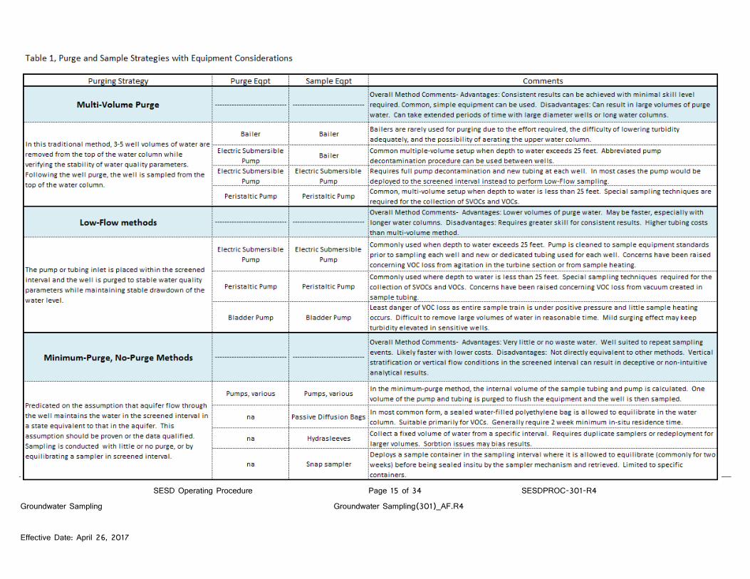
3 Groundwater Purging and Sampling 3.1 Overview of Purging and Sampling Strategies
Purging is the process of removing stagnant water from a well, immediately prior to sampling, causing its replacement by groundwater from the adjacent formation that is representative of aquifer conditions. Sampling is the process of obtaining, containerizing, and preserving (when required) a ground water sample after the purging process is complete. There are several approaches to well purging and sampling that may be appropriate in various circumstances or for various combinations of available equipment. They are briefly summarized below and in Table 1, Purge and Sample Strategies with Equipment Considerations. The Multiple-Volume Purge method involves removing a minimum of three well volumes of water from the top of the water column and then sampling when the well has achieved stability of water quality parameters and adequately low turbidity. This is a traditional method and consistent results are generally obtained with samplers of varying skill. A drawback is that large volumes of purge water may be produced for large diameter or deep wells. The Low-Flow method involves purging the well at a relatively low flow rate that minimizes drawdown, with the pump or tubing inlet located within the screened interval of the well. The well is sampled when water quality parameters are stable, adequately low turbidity is achieved, and the water level has achieved a stable drawdown (an unchanging water level). This method is often faster than Multiple-Volume Purge and generates less purge water. The method requires more skill and judgment on the part of the samplers. The Multiple-Volume Purge method and the Low-Flow method can be considered equivalent for conventionally screened and filter-packed wells in that they both sample a flow-weighted average of water entering the well during pumping. However, other variables can result in differences between results with the two methods. In repeat sampling events, the sampling design should not change from one method to the other without appropriate cause. The transition should be noted in the report. Minimum-Purge and No-Purge methods are based on the assumption that water within the screened interval of the well is at equilibrium with the water in the surrounding aquifer. This assumption should be carefully considered in the use of these methods and various cautions are discussed in sections below. The minimal-purge and no-purge methods are most useful for long-term monitoring and are generally inappropriate for the early stages of investigation. In some cases the methods might be used to gather screening-level data from wells that are too large to practically purge or have other sampling complications.
COPY

SESD Operating Procedure Page 13 of 34 SESDPROC-301-R4
Groundwater Sampling Groundwater Sampling(301)_AF.R4
Effective Date: April 26, 2017
The Minimum-Purge and No-Purge methods collect water in the vicinity of the device under near-static conditions and are not equivalent to the multiple-volume purge and Low-Flow methods. Stratification of horizontal flow or vertical flow conditions within the well can result in non-intuitive and deceptive results. A comparison study should be conducted before transitioning a sampling program to the minimal-purge or no-purge methods.
3.2 Purging
Wells are purged to eliminate stagnant water residing in the casing and/or screen that has undergone geochemical changes or loss of VOCs. At the conclusion of purging, the desired flow-weighted average of water entering the well under pumping conditions will be available for sampling. Turbidity is often elevated during purging by the disturbance of formation materials at the borehole walls. As many contaminants (metals and many organics) will sorb to the formation particles, a sample including these particles will not represent the dissolved concentrations of the contaminants. Thus, a secondary goal of purging is to reduce the turbidity to the point that the sample will represent the dissolved concentration of contaminants. In order to determine when a well has been adequately purged, field investigators should monitor, at a minimum, the pH, specific conductance and turbidity of the groundwater removed and the volume of water removed during purging. The measurements should be recorded in a purge table in the field logbook that includes the start time of purging, the parameter measurements at intervals during purging, estimated pumped volumes, depths to water for Low-Flow sampling, and any notes of unusual conditions. A typical purge table used for Low-Flow sampling is reproduced below.
COPY

SESD Operating Procedure Page 14 of 34 SESDPROC-301-R4
Groundwater Sampling Groundwater Sampling(301)_AF.R4
Effective Date: April 26, 2017
3.3 Parameter Stabilization Criteria With respect to the ground water chemistry, an adequate purge is achieved when the pH and specific conductance of the ground water have stabilized and the turbidity has either stabilized or is below 10 Nephelometric Turbidity Units (NTUs) (twice the Secondary Drinking Water Standard of 5 NTUs). Stabilization occurs when, for at least three consecutive measurements, the pH remains constant within 0.1 Standard Unit (SU) and specific conductance varies no more than 5 percent. Other parameters, such as dissolved oxygen (DO) or oxidation-reduction potential (ORP), may also be used as a purge adequacy parameter. Normal stability goals for DO are 0.2 mg/L or 10% change in saturation, whichever is greater. DO and ORP measurements must be conducted using either a flow-through cell or an over-topping cell to minimize oxygenation of the sample during measurement. A reasonable ORP stability goal is a range of 20 mV, although ORP is rarely at equilibrium in environmental media and often will not demonstrate enough stability to be used as a purge stabilization parameter. Determining the frequency of measurements has generally been left to ‘Best Professional Judgement’. Care is in order, as measurements recorded at frequent intervals with low flow rates can falsely indicate stability of parameters. Several measurements should be made early in the well purge to establish the direction and magnitude of trends, which can then inform the stability decision. Stability parameters should either be not trending, or approaching an asymptote, when a stability determination is made. As a matter of practice, parameter measurements are generally made at 5-10 minute intervals. Because the measured groundwater temperature during purging is subject to changes related to surface ambient conditions and pumping rates, its usefulness is subject to question for the purpose of determining parameter stability. As such, it has been removed from SESD’s list of parameters used for stability determination. Even though temperature is not used to determine stability, it is still advisable to record the temperature of purge water as it is often used in the interpretation of other parameters.
Information on conducting the stability parameter measurements is available in the SESD Operating Procedures for Field pH Measurement (SESDPROC-100), Field Specific Conductance Measurement (SESDPROC-101), Field Temperature Measurement (SESDPROC-102), Field Turbidity Measurement (SESDPROC-103), Field Measurement of Dissolved Oxygen (SESDPROC-106) and Field Measurement of Oxidation-Reduction Potential (SESDPROC-113).
COPY
SESD Operating Procedure Page 15 of 34 SESDPROC-301-R4
Groundwater Sampling Groundwater Sampling(301)_AF.R4
Effective Date: April 26, 2017
COPY

SESD Operating Procedure Page 16 of 34 SESDPROC-301-R4
Groundwater Sampling Groundwater Sampling(301)_AF.R4
Effective Date: April 26, 2017
3.4 Multiple-Volume Purge
In the traditional Multiple-Volume Purge method, water is removed from the top of the water column, causing water to enter the screen and flush stagnant casing water upward to be subsequently removed. In recognition of the mixing of fresh and stagnant water in the casing section, a minimum of three well volumes is removed, at which time purging can be terminated upon parameter stabilization. Wells can be assumed to be adequately purged when five well volumes have been removed, although further purging may be conducted to meet specific goals, such as further reduction of turbidity.
3.4.1 Purge Volume Determination Prior to initiating the purge, the amount of water standing in the water column (water inside the well riser and screen) should be determined The diameter of the well is determined and the water level and total depth of the well measured and recorded prior to inserting a pump or tubing into the well. The water level is subtracted from the total depth, providing the length of the water column. Specific methodology for obtaining these measurements is found in SESD Operating Procedure for Groundwater Level and Well Depth Measurement (SESDPROC-105). Once this information is obtained, the volume of water to be purged can be determined using one of several methods. The well volume can be calculated using the equation: V = 0.041 d2h Where:
h = length of water column in feet d = diameter of well in inches
V = one well volume in gallons Alternatively, the volume of standing water in the well and the volume of three water columns may be determined using a casing volume per foot factor for the appropriate diameter well, such as Table 2 Well Casing Diameter Volume Factors. The water column length is multiplied by the appropriate factor in the Table 2 to determine the single well volume, three well volumes, or five well volumes for the well in question. Other acceptable methods include the use of nomographs or other equations or formulae.
COPY

SESD Operating Procedure Page 17 of 34 SESDPROC-301-R4
Groundwater Sampling Groundwater Sampling(301)_AF.R4
Effective Date: April 26, 2017
TABLE 2, WELL CASING DIAMETER VOLUME FACTORS
Reference Minimum purge
Maximum purge*
1 Well Volume (gallons/ft)
3 Well Volumes (gallons/ft)
5 Well Volumes (gallons/ft)
Wel
l Cas
ing
Diam
eter
(in)
0.5 0.01 0.03 0.05 0.75 0.02 0.07 0.11 1 0.04 0.12 0.20 2 0.16 0.49 0.82 3 0.37 1.1 1.8 4 0.65 2.0 3.3 5 1.0 3.1 5.1 6 1.5 4.4 7.3 7 2.0 6.0 10.0 8 2.6 7.8 13.1 9 3.3 9.9 16.5 10 4.1 12.2 20.4 11 4.9 14.8 24.7 12 5.9 17.6 29.4 13 6.9 20.7 34.5 14 8.0 24.0 40.0 15 9.2 27.5 45.9 16 10.4 31.3 52.2 18 13.2 39.7 66.1 24 23.5 70.5 118 36 52.9 159 264 48 94.0 282 470
* See text for discussion on terminating purge at five well volumes An adequate purge is normally achieved when three to five well volumes have been removed. The field notes should reflect the single well volume calculations or determinations, according to one of the above methods, and a reference to the appropriate multiplication of that volume, i.e., a minimum three well volumes, clearly identified as an initial purge volume goal.
COPY

SESD Operating Procedure Page 18 of 34 SESDPROC-301-R4
Groundwater Sampling Groundwater Sampling(301)_AF.R4
Effective Date: April 26, 2017
3.4.2 Pumping Conditions
The pump or tubing inlet should be located at the top of the water column. If the pump is placed deep into the water column, the water above the pump may not be removed, and the subsequent samples, particularly if collected with a bailer, may not be representative of the aquifer conditions. If the recovery rate of the well is faster than the pump rate and no observable draw down occurs, the pump should be raised until the intake is as close as possible to the top of the water column for the duration of purging. If the pump rate ex-ceeds the recovery rate of the well, the pump or tubing will have to be lowered to accommodate the drawdown.
3.4.3 Stability of Chemical Parameters In the multiple-volume purge method, a stability determination may be made after three well volumes have been removed. If the chemical parameters have not stabilized according to the above criteria, additional well volumes (up to a total of five well volumes) should be removed. If the parameters have not stabilized after the removal of five well volumes, it is at the discretion of the project leader whether or not to collect a sample or to continue purging. If, after five well volumes, pH and conductivity have stabilized and the turbidity is still decreasing and approaching an acceptable level, additional purging should be considered to obtain the best sample possible.
3.4.4 Sample Collection There are several means by which sampling can proceed after adequate volume has been purged and water quality parameters have stabilized. If a submersible pump and tubing are of suitable material and cleanliness for sample collection, sampling can proceed immediately by directly filling bottles from the tubing outlet. Commonly with the multiple-volume purge method, the pump is set up and cleaned in a manner suitable only for purging. In these cases, the pump is stopped and removed from the well and sampling proceeds with a bailer per the procedure described in Section 3.6.3. The pump should have a check valve to prevent water in the pump tubing from discharging back into the well when the pump is stopped. If a peristaltic pump is used, sampling can proceed as described in Section 3.6.1.
3.5 Low-Flow Method This method involves placing the pump or tubing inlet within the screened interval of the well and purging at a low enough rate to achieve stable drawdown and minimal depression of the water level. The well is sampled without interruption after field parameters are stable and low turbidity is achieved. In general, only water in the screened interval of the well is pumped and the stagnant water in the well casing above the screen is not removed. Wells can generally be sampled in less time with less purge volume than with the multi-volume purge method. More attention is required in the assessment of stability criteria than the multi-volume method.
COPY

SESD Operating Procedure Page 19 of 34 SESDPROC-301-R4
Groundwater Sampling Groundwater Sampling(301)_AF.R4
Effective Date: April 26, 2017
3.5.1 Nomenclature A variety of terminology has been used to describe this method by SESD and others, including: ‘low flow’, ‘low-flow/low-volume’, ‘tubing-in-screen method’, ‘low flow/ minimal drawdown’, and ‘micropurge’. The current preferred SESD terminology for this method is ‘Low-Flow’. As the term ‘micropurge’ is sometimes used to refer to minimal-purge methods and has been trademarked by a vendor, the use of ‘micropurge’ to describe the Low-Flow method generally introduces ambiguity and confusion and thus the use of the term is discouraged.
3.5.2 Placement of Pump Tubing or Intake The inlet of the pump tubing or intake of the submersible pump is placed in the approximate mid-portion of the screened interval of the well. While it is often thought that particular aquifer zones can be targeted by specific pump or intake placement, for conventionally constructed screened and filter-packed monitoring wells the zone monitored is only weakly dependent on the intake placement (Varljen, Barcelona, Obereiner & Kaminski, 2006). The pump or tubing can be placed by carefully lowering them to the bottom of the well and then withdrawing half of the screen length, plus the length of any sump sections at the bottom of the well. A drawback of this approach is that it may stir up sediment at the well bottom. An alternate approach is to lower the pump or tubing a measured distance to place it at mid-screen without touching the bottom of the well. In the case of pumps, special care should be used in lowering them slowly, especially in the screened interval, to prevent elevating turbidity needlessly by the surging action of the pump.
3.5.3 Conditions of Pumping Prior to initiation of pumping, a properly decontaminated well sounder should be lowered into the well to measure the water level prior to and during the purging process. Ideally, there should be only a slight and stable drawdown of the water column after pumping begins. In some cases, it will be necessary for the well to drawdown a considerable distance (10 ft or more in extreme cases) to maintain a minimal usable pumping rate for sampling (100-200 ml/min). Excessive pump rates and drawdown can result in increased turbidity, or aeration of the sample if the screen is exposed. Stable drawdown is an essential condition of the Low-Flow method. If the stable drawdown condition cannot be met, then one of the other methods should be employed.
3.5.4 Stability of Chemical Parameters As with the Multiple-Volume Purging method described, it is important that all chemical parameters be stable prior to sampling. It is common for wells to require the removal of one of more screened-interval volumes (~2 gal for a 10 ft screen in a 2” dia. well) to achieve stability. Although it is possible for wells to achieve stability with lower purge volumes, the sampler should exercise caution in making an early stability determination.
COPY
SESD Operating Procedure Page 20 of 34 SESDPROC-301-R4
Groundwater Sampling Groundwater Sampling(301)_AF.R4
Effective Date: April 26, 2017
3.5.5 Sample Collection Low-Flow sampling is implemented using a pump and tubing suitable for sampling. After making the determination of parameter stability with stable drawdown, sampling can proceed immediately. Where submersible or bladder pumps are used, sampling can proceed by directly filling bottles from the tubing outlet. Where peristaltic pumps are used, sampling can proceed per the procedure described in Section 3.6.3.
3.6 Minimum-Purge and No-Purge Sampling The Minimum-Purge and No-Purge sampling methods are employed when it is necessary to keep purge volumes to an absolute minimum, where it is desirable to reduce long-term monitoring costs, or where large wells or other limitations prevent well purging. The underlying assumption when employing these methods is that the water within the well screen is equilibrated with the groundwater in the associated formation. This assumption should be demonstrated prior to use of these methods or the results suitably qualified. These methods are generally impractical for SESD to implement because of the common lack of hydrogeological information in early investigative phases and the necessity with some methods that the samplers be pre-deployed to allow equilibration. Vertical flow conditions and stratification of the water column have also been known to result in deceptive and non-intuitive analytical results. The use of these methods in the early phases of investigation can easily result in misinterpretation of site conditions and plume boundaries. Particular caution is in order in the use of these methods when any of the following conditions exist:
• Low hydraulic conductivity (K<10-5 cm/sec) • Low groundwater surface gradients • Fractured bedrock • Wells with long screened intervals • Wells screened in materials of varying hydraulic conductivities
If it is desired to transition a long-term monitoring program to Minimum-Purge or No-Purge sampling, a pilot study should be conducted where the Minimum-Purge or No-Purge sample results are compared to the conventional methods in use. Multiple samplers may be deployed in the screened interval to help establish appropriate monitoring intervals. These methods are in common use and for the purposes of the SESD quality system they can be considered standard, but unaccredited, procedures. Several Minimum-Purge or No-Purge procedures that might be employed are shown below. It is not the intention to recommend particular equipment or vendors, and other equipment that can accomplish the same goals may be suitable.
COPY

SESD Operating Procedure Page 21 of 34 SESDPROC-301-R4
Groundwater Sampling Groundwater Sampling(301)_AF.R4
Effective Date: April 26, 2017
3.6.1 Minimum Purge Sampling
The pump or tubing inlet is deployed in the screened interval. A volume of water equal to the internal pump and tubing volume is pumped to flush the equipment. Sampling then proceeds immediately. While superficially similar to Low-Flow sampling, the results obtained in this method will be sensitive to the vertical pump or tubing inlet placement and are subject to the limitations described above.
3.6.2 Passive Diffusion Bags
The no-purge Passive Diffusion Bag (PDB) typically consists of a sealed low-density polyethylene (LDPE) bag containing deionized water. They are deployed in the screened interval of a well and allowed to equilibrate, commonly for two weeks, prior to retrieval and decanting of the water into sample containers. Many volatile organic compounds will reach equilibrium across the LDPE material, including BTEX compounds and many chlorinated solvents. Compounds showing poor equilibration across LDPE include acetone, MTBE, MIBK, and styrene. PDBs have been constructed of other materials for sampling other analytes, but the vast majority of PDB samplers are of the LDPE material. Various vendors and the Interstate Technology and Regulatory Council (ITRC) can provide additional information on these devices.
3.6.3 HydraSleevesTM
HydraSleeevesTM are no-purge grab sampling devices consisting of a closed-bottom sleeve of low-density polyethylene with a reed valve at the top. They are deployed in a collapsed state to the desired interval and fill themselves through the reed valve when pulled upward through the sampling interval. The following is a summary of their operation:
Sampler placement – A reusable weight is attached to the bottom of the sampler or the sampler is clipped to a weighted line. The HydraSleeveTM is lowered on the weighted line and placed with the top of the sampler at the bottom of the desired sampling interval. In-situ water pressure keeps the reed valve closed, preventing water from entering the sampler. The well is allowed to return to equilibrium. Sample collection - The reed valve opens to allow filling when the sampler is moved upward faster than 1 foot per second, either in one continuous upward pull or by cycling the sampler up and down to sample a shorter interval. There is no change in water level and only minimal agitation during collection. Sample retrieval - When the flexible sleeve is full, the reed valve closes and the sampler can be recovered without entry of extraneous overlying fluids. Samples are removed by puncturing the sleeve with the pointed discharge tube and draining the contents into containers for sampling or field parameter measurements.
COPY
SESD Operating Procedure Page 22 of 34 SESDPROC-301-R4
Groundwater Sampling Groundwater Sampling(301)_AF.R4
Effective Date: April 26, 2017
Because the HydraSleeveTM is retrieved before equilibration can occur and they are constructed of non-Teflon® materials, there may be issues with sorbtion of contaminants in the use of this sampler.
3.6.4 Snap Samplers
The Snap Sampler is a patented no-purge groundwater sampling device that employs a double-end-opening bottle with “Snap” sealing end caps. The dedicated, device is deployed at the desired position in the screened interval with up to six Snap Samplers and six individual sampling bottles. The device is allowed to equilibrate in the screened interval and retrieved between 3 and 14 days after deployment. Longer deployments are possible to accommodate sampling schedules. To operate, Snap Samplers are loaded with Snap Sampler bottles and the "Snap" caps are set into an open position. Samplers are deployed downhole with an attachment/trigger line and left to equilibrate downhole. To collect samples, the Snap Sampler bottles seal under the water surface by pulling a mechanical trigger line, or using an electric or pneumatic trigger system. The trigger releases Teflon® "Snap Caps" that seal the double-ended bottles. The end caps are designed to seal the water sample within the bottles with no headspace vapor. After the closed vial is retrieved from the well, the bottles are prepared with standard septa screw caps and labeled for laboratory submittal. The manufacturer of the Snap Sampler provides considerable additional information on the validation and use of the device.
3.7 Equipment Considerations
Equipment choices are dictated by the purging and sampling method used, the depth to water, the quantity of water to be pumped, and quality considerations. The advantages and disadvantages of various commonly used pumps are discussed in the sections below and summarized in Table 1, Purge and Sample Strategies with Equipment Considerations. Additional information on the use of individual pumps is available in SESD Operating Procedure for Pump Operation, SESDPROC-203.
3.7.1 Use of Peristaltic Pumps
Peristaltic pumps are simple, inexpensive, and reliable equipment for purging and sampling where the limit of suction is not exceeded (approximately 25-30 vertical feet from the groundwater surface to the pump). When used for sampling, they should be equipped with new Teflon® tubing for each well. The flexible peristaltic pump-head tubing should also be changed between wells. Samples for organic analyses cannot be exposed to the flexible peristaltic pump-head tubing, both due to the risk that the tubing would sorb contaminants and the propensity of this tubing to contribute organic compounds to the sample. Samples can be collected without contact with the pump-head tubing by the use of vacuum transfer caps for
COPY

SESD Operating Procedure Page 23 of 34 SESDPROC-301-R4
Groundwater Sampling Groundwater Sampling(301)_AF.R4
Effective Date: April 26, 2017
analyses requiring 1 liter glass containers and the use of the ‘soda-straw’ method for the filling of VOC vials. The sample containers for the more turbidity-sensitive analyses are filled first, as filling the VOC vials (and to a lesser extent the glass bottles) may disturb the well and increase turbidity. The most appropriate order of sampling with a peristaltic pump is generally to fill poly containers for metals and classical analyses, followed by glass bottles for SVOCs and associated analyses, and finally to fill 40 ml VOC vials. The following step-by-step procedure assumes that the pump has been set up per SESD Operating Procedure for Pump Operation (SESDPROC-203) and that containers for a typical full suite of analyses will be filled. The procedure is suitable for use with either multi-volume Purge and Low-Flow methods with minor differences in the collection of VOCs:
1. Deploy the lower end of the tubing to the desired point in the well. This would
be the top-of-water for the multi-volume purge method or to the mid-screen for the Low-Flow method. Connect the well tubing to the flexible pump-head tubing and connect a short piece of tubing from the pump-head tubing to a measuring bucket.
2. Turn on the pump and establish a suitable pumping rate. For the multi-volume purge method, the rate will generally be a relatively fast rate that the well will sustain without elevating turbidity. For the low-flow method the pump rate is established at a slower rate to maintain a minimal and stable drawdown level.
3. Proceed with the measurement of water quality parameters and adjust the pump rate as needed to achieve low turbidity and stable drawdown.
4. When the well purge has been determined to be sufficient, fill containers for
metals and classical analyses directly from the pump outlet. There is no need to interrupt pumping. The tubing should be held at the opening of the container and should not touch the container during filling. Protect caps from dust and debris during filling.
5. After filling the containers for metals and classical analyses stop the pump.
Make sure that the tubing leading into the well is secured against movement during the following operations.
6. Create a crimp in the well tubing approximately one foot from the pump and
grasp the crimped tubing in one hand. It is generally most effective to create a double ‘Z’ crimp.
7. Cut the sample tubing between the crimp and the pump. The tightly-held
crimped tubing should keep water from running back into the well. In lieu of
COPY
SESD Operating Procedure Page 24 of 34 SESDPROC-301-R4
Groundwater Sampling Groundwater Sampling(301)_AF.R4
Effective Date: April 26, 2017
cutting the tubing, the well tubing can be disconnected from the pump and a short piece of tubing connected in its place.
8. Insert both free ends of the tubing into the ferrule-nut fittings of a pre-cleaned
Teflon® transfer cap assembly and tighten the nuts. Attach the transfer cap assembly to the first glass container for semi-volatile analysis and securely tighten the threaded ring.
9. Turn the pump on. Very slowly release the ‘Z’ crimp in the sample tubing. As
vacuum builds up in the sample container, water should begin to move up the sample tubing instead of back into the well. If after several minutes water has not begun moving up the tubing, check the tightness of fittings and the attachment of the cap to the bottle. Allowing water to rush back down the tubing from the ‘Z’ crimp can surge the well and elevate turbidity.
10. Fill the container to about halfway between the shoulder and the neck. Crimp
the well tubing. Move the transfer cap to any additional bottles and repeat the filling process.
11. When finished filling bottles with the transfer cap, again crimp the tubing.
Remove the well tubing from the transfer cap and reattach it to the pump. Slowly run the pump and release the crimp until water is approaching the flexible peristaltic tubing.
12. Make a kink or otherwise mark the tubing at the top of the casing in case the
tubing needs to be reinserted for additional sample volume. Slowly remove the tubing from the well and coil it in one hand in loose coils. With the top end of the tubing blocked, water is retained in the tubing as it is withdrawn, much as in a capped soda straw, hence the name for this method.
13. Remove the top from a 40 ml VOC vial and position the end of the sample
tubing near the top of the vial. Reverse the pump direction and turn the speed knob to its slowest position. Turn on the pump and slowly increase speed until water slowly fills the vial. Fill the vial with a slow laminar flow that does not agitate the water in the vial or entrain bubbles. Continue to fill the vial until a convex meniscus forms on the top of the vial and turn off the pump.
14. Carefully screw the septum-lid to the vial and fasten firmly. Invert the vial and
tap on your knuckles to check for bubbles. Carefully add additional volume to the vial if necessary. Small bubbles are undesirable but may be unavoidable with some media, especially when using pre-preserved vials.
15. Repeat the filling process for additional vials. Avoid partially filling vials as the
available water in the tubing is used. If more volume is required than that contained in the tubing, purge the remaining water from the tubing and reinsert
COPY

SESD Operating Procedure Page 25 of 34 SESDPROC-301-R4
Groundwater Sampling Groundwater Sampling(301)_AF.R4
Effective Date: April 26, 2017
the tubing in the well to the level marked previously. Run the pump to refill the tubing. If performing Low-Flow sampling, run additional volume through the pump to purge any water that may have been collected from the stagnant water column.
16. Fill additional vials as needed. Be sure that any water that has contacted the
flexible peristaltic tubing is not pumped into a vial.
3.7.2 Use of Submersible Centrifugal Pumps
Submersible centrifugal pumps are used in wells of 2” diameter and larger. They are especially useful where large volumes of water are to be removed or when the groundwater surface is a large distance below ground surface. Commonly used pumps are the Grundfos® Redi-Flo2, the Geotech GeoSub, and the various ‘Monsoon’ style pumps. Other pumps are acceptable if constructed of suitable materials. When used with the Multiple-Volume Purge method, the pump is generally used only to purge, with sampling performed with a bailer. In this use, the pump can be used with polyethylene or other tubing or hose that will not contribute contaminants to the well. The pump and tubing is decontaminated between wells per the relevant provisions of SESD Operating Procedure for Field Equipment Cleaning and Decontamination (SESDPROC-205). When used in this application the pump should be equipped with a check valve to prevent water in the discharge tubing or hose from running back down into the well. When used for Low-Flow purging and sampling the pump must be constructed of stainless steel and Teflon®. Pump cleaning at each well follows the more stringent procedures described in SESD Operating Procedure for Field Equipment Cleaning and Decontamination SESDPROC-205) for this application. The sample tubing should be either new Teflon® tubing, or tubing dedicated to each well. Dedicated tubing would ideally be cleaned between uses, but tubing stored in the well casing between uses is acceptable, although caution should be exercised where very high concentrations of contaminants have been sampled in a well.
3.7.3 Use of Bailers Bailers are a common means of sampling when the Multiple-Volume Purge method is used. They are occasionally used for purging when other equipment is not available or has failed. As bailers surge the well on each withdrawal, it is very difficult to lower turbidity adequately during a well purge, and when used for sampling they can elevate turbidity in a well before all sample volume is collected. If not lowered carefully into the top of the water column, the agitation may strip volatile compounds. Due to the difficulties and limitations inherent in their use, other sampling or purging means should generally be given preference.
COPY
SESD Operating Procedure Page 26 of 34 SESDPROC-301-R4
Groundwater Sampling Groundwater Sampling(301)_AF.R4
Effective Date: April 26, 2017
Bailers should be closed-top Teflon® bailers with Teflon® coated stainless steel leaders used with new nylon haul rope. They are lowered gently into the top of the water column, allowed to fill, and removed slowly. It is critical that bailers be slowly and gently immersed into the top of the water column, particularly during final stages of purging and during sampling, to minimize turbidity and loss of volatile organic constituents. If the well has previously been purged with a pump, there is likely stagnant water at the top of the well that was above the pump or tubing inlet. Several bailers of water should be retrieved and discarded to assure the upper stagnant water has been removed. When sampling, containers are filled directly by pouring from the outlet at the top of the bailer. Containers for metals analysis should be filled first in case the bailing process increases well turbidity. VOC vials should be filled carefully and slowly with a laminar flow to reduce agitation and the stripping of VOCs.
3.7.4 Use of Bladder Pumps Bladder pumps use a source of compressed gas to compress and release a bladder straddled by check valves within the pump body. As the bladder is compressed, water is expelled out the upper check valve to the surface. When gas pressure is released, the bladder refills as well water enters the lower pump inlet. A control unit is used to control the pressure and timing of the bladder inflation gas flow. Bladder pumps are capable of pumping from moderate depths to water, but are not capable of high flow rates. As they operate cyclically, the well is surged slightly on each cycle and it may be difficult to lower turbidity in sensitive or poorly developed wells. As the entire sample train is under positive pressure and the pumps develop little heat, they are ideal for sampling VOCs. Prior to sampling and between each well the pumps are cleaned internally and externally per the provisions of SESD Operating Procedure for Field Decontamination (SESDPROC-205) and a new Teflon® bladder installed. New (or dedicated) Teflon® sample tubing is used at each well, although polyethylene tubing can be used for the compressed gas drive line and cleaned between each well.
3.7.5 Use of Inertial Pumps Inertial pumps consist of a check valve which is affixed to the lower end of semi-rigid tubing. The tubing and valve are cycled up and down, allowing water to alternately be drawn into the check valve inlet and then pulled up towards the surface. Two commonly used inertial pumps are the Waterrra® pump for wells 1arger than 1” and the Geoprobe® Tubing Check Valve for small diameter wells. The primary use of these pumps is in well development where their near-immunity to silt is an advantage. Inertial pumps should not be used for the final well purge or for sampling as there is a low likelihood of
COPY

SESD Operating Procedure Page 27 of 34 SESDPROC-301-R4
Groundwater Sampling Groundwater Sampling(301)_AF.R4
Effective Date: April 26, 2017
reducing turbidity to appropriate levels and they have the potential to strip volatiles from the water column through agitation. To set up the pump, the check valve is screwed onto the discharge tubing where it will cut its own threads. In the case of the Waterra® pump, a surge block can also be pressed onto the check valve. The pump is lowered into the well to the screened interval and rapidly cycled up and down a distance of 3” -12”. The stroke length and speed are adjusted for pumping effect. Electric actuators can be used to reduce the effort involved. The pump should be moved to different levels in the screen to surge the entire screen. The pump can occasionally be lowered to the bottom of the well to vacuum out silt. Any silt that clogs the valve is usually quickly rinsed out by the pump cycling and if the clog remains the pump is easily retrieved and redeployed. The surging activity is usually continued until turbidity is lowered to a measurable range and cannot easily be lowered further. Further development or purging is then conducted with other pumps.
3.8 Wells With In-Place Plumbing
Wells with in-place plumbing are commonly found at municipal water treatment plants, industrial water supplies, private residences, and in other applications. Many permanent monitoring wells at active facilities are also equipped with dedicated, in-place pumps. A permanent monitoring well with an in-place pump may be treated as other monitoring wells without pumps. Since the in-place pump is generally “hard” mounted at a pre-selected depth, it cannot be moved up or down during purging and sampling. If the pump inlet is above the screened interval, the well should be sampled using the Multiple-Volume Purge method. If the pump intake is located within the screened interval, the well can be sampled using Low-Flow procedures. Known details of pump type and construction, tubing types, pump setting depths, and any other available information about the system should be recorded in the field logbook. In the case of the other types of wells, e.g., municipal, industrial and residential supply wells, there is typically not enough known about the construction aspects of the wells to apply the same criteria as used for monitoring wells. The volume to be purged in these situations therefore depends on several factors: whether the pumps are running continuously or intermittently and whether or not any storage/pressure tanks are located between the sampling point and the pump. The following considerations and procedures should be followed when purging wells with in-place plumbing under the conditions described.
3.8.1 Continuously Running Pumps If the pump runs more or less continuously, no purge (other than opening a valve and allowing it to flush for a few minutes) is necessary. If a storage tank is present, a spigot,
COPY

SESD Operating Procedure Page 28 of 34 SESDPROC-301-R4
Groundwater Sampling Groundwater Sampling(301)_AF.R4
Effective Date: April 26, 2017
valve or other sampling point should be found located between the pump and the storage tank. If no valve is present, locate and use the valve closest to the tank. Measurements of field parameters are recorded immediately prior to the time of sampling.
3.8.2 Intermittently or Infrequently Running Pumps If the pump runs intermittently or infrequently, best judgment should be utilized to remove enough water from the plumbing to flush standing water from the piping and any storage tanks that might be present. Often under these conditions, 15 to 30 minutes of purging will be adequate. Measurements of pH, specific conductance, temperature and turbidity should be made and recorded at intervals during the purge and the final measurements made at the time of sampling should be considered the measurements of record for the event.
3.9 Temporary Monitoring Wells
3.9.1 General Considerations As temporary wells are installed for immediate sample acquisition, the procedures used to purge temporary ground water monitoring wells may differ from those for permanent wells. Temporary wells include standard well screen and riser placed in boreholes created by hand augering or drilling, or they may consist of a drive rod and screen such as a direct-push Geoprobe® Screen Point that is driven into place at the desired sampling interval. As aquifer water enters the sampler immediately upon deployment, the requirement to remove several volumes of water to replace stagnant water does not necessarily apply. In practice, developing and purging the well to usable turbidity levels will remove many times the water that would be removed in a Multiple-Volume Purge with calculated well volumes. It is important to note, however, that the longer a temporary well is in place and not sampled, the more stagnant the water column becomes and the more appropriate it becomes to apply standard permanent monitoring well purging criteria to achieve representative aquifer conditions in the sample. 3.9.2 Development of Temporary Wells In cases where the temporary well is to be sampled immediately after installation, purging is conducted primarily to mitigate the impacts of installation. In most cases, temporary well installation procedures disturb the existing aquifer conditions, causing extreme turbidity. The goal of purging is to reduce the turbidity and remove the volume of water in the area directly impacted by the installation procedure. The following procedure has been found to be effective in developing and sampling small diameter temporary wells where a peristaltic pump can be used. Turbidity can generally be lowered to 50 NTU at the time of sampling and turbidity less than 10 NTU is often achieved.
COPY

SESD Operating Procedure Page 29 of 34 SESDPROC-301-R4
Groundwater Sampling Groundwater Sampling(301)_AF.R4
Effective Date: April 26, 2017
1. Cut peristaltic tubing to reach to the bottom of the well. Connect to a peristaltic pump and begin pumping at a high rate.
2. Use the tubing to vacuum out sediment at the bottom of the well.
3. Aggressively surge the end of the tubing in the screened interval by cycling the tubing rapidly up and down. Periodically repeat vacuuming of the well bottom.
4. When a visible ‘break’ to a lower turbidity is observed, cease surging the well and begin lowering the pumping rate.
5. When the water clears (turbidity < 100-200 NTU) begin raising the end of the tubing to the top of the water column.
6. Continue purging from the top of the water column, lowering the pump speed as required to lower turbidity. When adequately low turbidity and stable water quality parameters have been achieved, sampling can proceed.
Where the water level is below the limit of suction in a small diameter temporary well, a Geoprobe® mechanical bladder pump can be used for purging and sampling. The well should first be developed with an inertial pump to remove the bulk of silt and suspended particles that could clog the check valves of the bladder pump. The inertial pump is used to vacuum out the bottom of the well and surged in the screened interval until a ‘break’ to lower turbidity is observed prior to deployment of the bladder pump. Since the mechanical bladder pump requires cumbersome redeployment to change its pumping level, it should be deployed low enough in the water column that the water level will not be lowered below the pump during purging and sampling. The mechanical bladder pump is generally deployed above the screened interval to facilitate the settling of particles, but below the top of the water column to alleviate the need to reset the pump. Detailed instructions on the deployment of the pump can be found in SESDPROC203, Pump Operation.
3.9.3 Decommissioning of Temporary Wells
After temporary wells have fulfilled their purpose, they should be properly decommissioned similar to permanent wells. In general, the casings and screens can be easily removed and the borehole should then be pressure grouted from the bottom of the original borehole to prevent surface contamination of the aquifer, cross-connection of aquifers, and to remove a potential vapor pathway. Direct-push screen-point wells may be decommissioned by one of two methods. 1. A disposable screen is used. The sampling sheath is pulled off of the screen and a
30% solids bentonite grout is pumped down the tool string as the rods are withdrawn.
COPY
SESD Operating Procedure Page 30 of 34 SESDPROC-301-R4
Groundwater Sampling Groundwater Sampling(301)_AF.R4
Effective Date: April 26, 2017
Grout volumes are measured during pumping to assure that the hole is completely filled. The disposable screen is left behind at the bottom of the borehole.
2. The screen is removed with the sampler sheath and tool string. The hole is immediately re-entered with an empty sample sheath with disposable point. Upon reaching the original total depth of the temporary well, 30% solids bentonite grout is pumped down the tool string with the pumped volume monitored during tool string withdrawal to assure that the hole is completely filled.
A system is available to insert a small diameter grouting tube down through the screen-point screen. Grout is pumped through the grouting tube while the tools are withdrawn. SESD does not use this system as grout denser than 20% solids cannot reliably be installed with this system. Additional guidance on decommissioning may be found in SESDGUID-101, Design and Installation of Monitoring Wells.
3.9.4 Other Considerations for Direct-Push Groundwater Sampling With certain direct push sampling techniques, such as the Hydropunch™ and other discrete samplers used with cone-penetrometer rigs, purging is either not practical or not possible. The sampling device is simply pushed or driven to the desired depth and opened, whereupon the sample is collected and retrieved. As a result, some samples collected in this way may not be satisfactory or acceptable for certain analyses, i.e., the sampler may collect a turbid sample inappropriate for metals analyses or the sample may have inadequate volume to achieve desired reporting levels.
3.10 Wells Purged to Dryness
In some situations, even with slow purge rates, a well may be purged dry in the Multiple-Volume Purge method or stable drawdown cannot be maintained in the Low-Flow method. In these cases, the well should be purged to dryness (evacuated) and sampled upon recovery of adequate volume for sampling. Sampling should occur as soon as adequate volume has recovered. The field parameters should be measured and recorded at the time of sample collection as the measurements of record for the sampling event. Sampling under these conditions is not ideal and suitable qualifications of the data should be included in the report. Water cascading down the screen into the well may strip volatile compounds and elevate turbidity. Although suffering from other limitations, No-Purge methods may prove useful for these wells.
COPY

SESD Operating Procedure Page 31 of 34 SESDPROC-301-R4
Groundwater Sampling Groundwater Sampling(301)_AF.R4
Effective Date: April 26, 2017
4 Additional Purging and Sampling Considerations 4.1 Field Care of Purging Equipment
New plastic sheeting should be placed on the ground surface around the well casing to prevent contamination of the pumps, hoses, ropes, etc., in the event they accidentally come into contact with the ground surface or, for some reason, they need to be placed on the ground during the purging event. It is preferable that hoses used in purging that come into contact with the ground water be kept on a spool or contained in a large wash tub lined with plastic sheeting, both during transportation and during field use, to further minimize contamination by the transporting vehicle or the ground surface. Careful consideration shall be given to using submersible centrifugal or bladder pumps to purge wells which are excessively contaminated with oily compounds as it may be difficult to adequately decontaminate severely contaminated pumps under field conditions. When wells of this type are encountered, alternative equipment, such as bailers or peristaltic pumps, should be considered.
4.2 Investigation Derived Waste
Purging and field cleaning of equipment generates liquid investigation derived waste (IDW), the disposition of which must be considered. See SESD Operating Procedure for Management of Investigation Derived Waste (SESDPROC-202) for guidance on management or disposal of this waste.
4.3 Sample Preservation
After sample collection, all samples requiring preservation must be preserved as soon as practical. Consult the Analytical Services Branch Laboratory Operations and Quality Assurance Manual (ASBLOQAM) for the correct preservative for the particular analytes of interest. All samples preserved using a pH adjustment (except VOCs) must be checked, using pH strips, to ensure that they were adequately preserved. This is done by pouring a small volume of sample over the strip. Do not place the strip in the sample. Samples requiring reduced temperature storage should be placed on ice immediately.
4.4 Special Sample Collection Procedures
4.4.1 Trace Organic Compounds and Metals
Special sample handling procedures should be instituted when trace contaminant samples are being collected. All sampling equipment, including pumps, bailers, water level measurement equipment, etc., which contacts the water in the well must be cleaned in accordance with the cleaning procedures described in the SESD Operating Procedure for Field Equipment Cleaning and Decontamination (SESDPROC-205) or SESD Operating Procedure for Field Equipment Cleaning and Decontamination at the FEC (SESDPROC-
COPY

SESD Operating Procedure Page 32 of 34 SESDPROC-301-R4
Groundwater Sampling Groundwater Sampling(301)_AF.R4
Effective Date: April 26, 2017
206). Pumps should not be used for sampling unless the interior and exterior portions of the pump and the discharge hoses are thoroughly cleaned. Rinse blank samples should be collected to verify the adequacy of cleaning when using a sampling pump other than a peristaltic pump. 4.4.2 Order of Sampling with Respect to Analytes In many situations when sampling permanent or temporary monitoring wells, sufficiently low turbidity is difficult to achieve and maintain. Removal and insertion of equipment after the purge or during sampling may negate the low turbidities achieved during purging and elevate turbidity back to unacceptable levels. For this reason, it is important that special efforts be used to minimize any disturbance of the water column after purging and to fill sample containers for metals analysis first. The preferred order of sampling is metals first, followed by other inorganic analytes, extractable organic compounds, and finally volatile organic compounds.
4.5 Filtering As many contaminants are known to sorb to soil particles, the normal goal of sampling is to reduce the presence of these particles (measured by turbidity) in order that the dissolved concentration of contaminants can be obtained. However, transport of sorbed contamination on colloidal particles can be a means of contaminant transport on some sites. For this reason, the SESD approach is to reduce turbidity through the careful purging of wells, rather than through filtering of samples, in order that the colloidal particles would be included in the sample. As a standard practice, ground water samples will not be filtered for routine analysis. Filtering will usually only be performed to determine the fraction of major ions and trace metals passing the filter and used for flow system analysis and for the purpose of geochemical speciation modeling. Filtration is not acceptable to correct for improperly designed or constructed monitoring wells, inadequate well development, inappropriate sampling methods, or poor sampling technique. When samples are collected for routine analyses and are filtered, both filtered and non-filtered samples will be submitted for analyses. Samples for organic compounds analysis should not be filtered. Prior to filtration of the ground water sample for any reason other than geochemical speciation modeling, the following criteria must be demonstrated to justify the use of filtered samples for inorganic analysis: 1. The monitoring wells, whether temporary or permanent, have been constructed and
developed in accordance with the SESD Guidance Document, Design and Installation of Monitoring Wells (SESDGUID-001).
2. The ground water samples were collected using sampling techniques in accordance
with this section, and the ground water samples were analyzed in accordance with USEPA approved methods.
COPY

SESD Operating Procedure Page 33 of 34 SESDPROC-301-R4
Groundwater Sampling Groundwater Sampling(301)_AF.R4
Effective Date: April 26, 2017
3. Efforts have been undertaken to minimize any persistent sample turbidity problems.
These efforts may consist of the redevelopment or re-installation of permanent ground water monitoring wells or the implementation of carefully conducted low flow rate sampling techniques.
If filtration is necessary for purposes of geochemical modeling or other pre-approved cases, the following procedures are suggested: 1. Accomplish in-line filtration through the use of disposable, high capacity filter
cartridges (barrel-type) or membrane filters in an in-line filter apparatus. The high capacity, barrel-type filter is preferred due to the higher surface area associated with this configuration. If a membrane filter is utilized, a minimum diameter of 142 mm is suggested.
2. When using pumps for sampling, the filter can generally be attached directly to the
pump outlet. When sampling with a bailer or when otherwise required, an initial unfiltered sample with extra volume will be collected, and a peristaltic pump with filter used to decant and filter the sample to the final sample container.
3. Use a 0.45 μm pore-size filter to remove most non-dissolved particles. A 5 µm or
10 µm pore-size filter should be used for the purpose of determining colloidal constituent concentrations.
4. Fill the filter and rinse with approximately one additional filter volume prior to
filling sample bottles Potential differences can result from variations in filtration procedures used to process water samples for the determination of trace element concentrations. A number of factors associated with filtration can substantially alter "dissolved" trace element concentrations; these include filter pore size, filter type, filter diameter, filtration method, volume of sample processed, suspended sediment concentration, suspended sediment grain-size distribution, concentration of colloids and colloidally-associated trace elements, and concentration of organic matter. Therefore, consistency is critical in the comparison of short-term and long-term results. Further guidance on filtration may be obtained from the following: 1) Metals in Ground Water: Sampling Artifacts and Reproducibility; 2) Filtration of Ground Water Samples for Metals Analysis; and 3) Ground Water Sampling - A Workshop Summary. See Section 1.4, References, for complete citation for these documents.
4.6 Bacterial Sampling Whenever wells (normally potable wells) are sampled for bacteriological parameters, care must be taken to ensure the sterility of all sampling equipment and all other equipment entering the well. Further information regarding bacteriological sampling is available in the following: 1) Sampling for Organic Chemicals and Microorganisms in
COPY

SESD Operating Procedure Page 34 of 34 SESDPROC-301-R4
Groundwater Sampling Groundwater Sampling(301)_AF.R4
Effective Date: April 26, 2017
the Subsurface; 2) Handbook for Evaluating Water Bacteriological Laboratories; and 3) Microbiological Methods for Monitoring the Environment, Water and Wastes. See Section 1.4, References, for complete citation for these documents.
4.7 Specific Sampling Equipment Quality Assurance Techniques
All equipment used to collect ground water samples shall be cleaned as outlined in the SESD Operating Procedure for Field Equipment Cleaning and Decontamination (SESDPROC-205) or SESD Operating Procedure for Field Equipment Cleaning and Decontamination at the FEC (SESDPROC-206). Malfunctioning equipment should be labeled in the field and repaired, before being stored at the conclusion of field studies. Cleaning procedures utilized in the field or field repairs shall be thoroughly documented in field records.
4.8 Auxiliary Data Collection
During ground water sample collection, it is important to record a variety of ground water related data. Included in the category of auxiliary data are water levels measured according to the SESD Operating Procedure for Groundwater Level and Well Depth Measurement (SESDPROC-105), well volume determinations, pumping rates during purging, and, driller or boring logs. This information should be documented in the field records.
4.9 Well Development
Wells may be encountered that are difficult to sample effectively due to inadequate initial development or the need for redevelopment due to scaling, sedimentation, corrosion, or biofouling. These wells may produce water only at low flow rates or water with chronically elevated turbidity. Redevelopment of these wells should be considered as the process can improve sample quality and speed field operations. Well development procedures are described in Design and Installation of Monitoring Wells (SESDGUID-101).
COPY


![LLVM MC in Practice · 2019. 10. 30. · _fac: push {r4, r7, lr} ldr! r0, [pc, #20] mov r1, #1 add r7, sp, #4 ldr! r0, [pc, r0] mov! r2, r1 ldr! r0, [r0] b! #0 # 4 bytes of data:.long](https://img.pdfslide.us/doc/110x75/60c63395503ad85a6a26c0e3/llvm-mc-in-practice-2019-10-30-fac-push-r4-r7-lr-ldr-r0-pc-20-mov.jpg)