Embed Size (px)
Citation preview
CopperLink™ Model 1211/1212High Speed Ethernet Extender
User Manual
This is a Class A device and is not intended for use in a residential environment.
Sales Office: +1 (301) 975-1000Technical Support: +1 (301) 975-1007
E-mail: [email protected]: www.patton.com
Part Number: 07MCL1212-UM, Rev. CRevised: December 12, 2014

Patton Electronics Company, Inc.7622 Rickenbacker Drive
Gaithersburg, MD 20879 USATel: +1 (301) 975-1000Fax: +1 (301) 869-9293
Support: +1 (301) 975-1007Web: www.patton.com
E-mail: [email protected]
Trademark StatementThe term CopperLink is a trademark of Patton Electronics Company. All other trade-
marks presented in this document are the property of their respective owners.
Copyright © 2014, Patton Electronics Company. All rights reserved.The information in this document is subject to change without notice. Patton Electronics assumes no liability for errors that may appear in this document.
Warranty InformationPatton Electronics warrants all CopperLink components to be free from defects, and will—at our option—repair or replace the product should it fail within one year from
the first date of the shipment.
This warranty is limited to defects in workmanship or materials, and does not cover customer damage, abuse or unauthorized modification. If the product fails to perform
as warranted, your sole recourse shall be repair or replacement as described above. Under no condition shall Patton Electronics be liable for any damages incurred by the use of this product. These damages include, but are not limited to, the following: lost profits, lost savings and incidental or consequential damages arising from the use of or inability to use this product. Patton Electronics specifically disclaims all other warran-ties, expressed or implied, and the installation or use of this product shall be deemed
an acceptance of these terms by the user.

3
Summary Table of Contents
1 General information .......................................................................................................................................... 12
2 Installation ........................................................................................................................................................ 15
3 Configuration .................................................................................................................................................... 20
4 Operation .......................................................................................................................................................... 24
5 Contacting Patton for assistance......................................................................................................................... 26
A Compliance Information ................................................................................................................................... 29
B Specifications .................................................................................................................................................... 32
C Factory Replacement Parts and Accessories ........................................................................................................ 34
D Interface Pin Assignment .................................................................................................................................. 36
E Line Rate & Reach Chart .................................................................................................................................. 38

Table of Contents
Summary Table of Contents ...................................................................................................................................3Table of Contents ...................................................................................................................................................4List of Figures .........................................................................................................................................................6List of Tables ..........................................................................................................................................................7About This Guide ..................................................................................................................................................8
Safety When Working With Electricity ...........................................................................................................10
1 General information .......................................................................................................................................... 12Overview ...............................................................................................................................................................13
Features .................................................................................................................................................................13
Description............................................................................................................................................................13
2 Installation ........................................................................................................................................................ 15Planning the Installation........................................................................................................................................16
Connecting the Line Interface ...............................................................................................................................17
Connecting the Line Interface for CL1212 .....................................................................................................17
Connecting the Line Interface for CL1212/BNC ............................................................................................18
Connecting the 10/100Base-T Ethernet Interface..................................................................................................18
Connecting Power .................................................................................................................................................19
3 Configuration .................................................................................................................................................... 20Introduction ..........................................................................................................................................................21
Accessing the DIP Switches ...................................................................................................................................21
Configuring DIP Switch S1...................................................................................................................................22
Switch S1-1: Local/Remote Configuration ......................................................................................................22
Switches S1-2 and S1-3: Symmetric/Asymmetric Operation ...........................................................................22
Switch S1-5: General Protection (Signal to Noise Ratio) .................................................................................23
4 Operation .......................................................................................................................................................... 24Introduction ..........................................................................................................................................................25
Front Panel LED Status Monitors .........................................................................................................................25
5 Contacting Patton for assistance......................................................................................................................... 26Introduction ..........................................................................................................................................................27
Contact information..............................................................................................................................................27
Warranty Service and Returned Merchandise Authorizations (RMAs)...................................................................27
Warranty Coverage .........................................................................................................................................27
Out-of-Warranty Service .................................................................................................................................27
Returns for Credit ...........................................................................................................................................27
RMA Numbers ...............................................................................................................................................28
Shipping Instructions ......................................................................................................................................28
A Compliance Information ................................................................................................................................... 29Regulatory Information .........................................................................................................................................30
EMC Directive: ..............................................................................................................................................30
4
CopperLink 1211/1212 User Manual
Low-Voltage Directive (Safety): ......................................................................................................................30
PSTN: ............................................................................................................................................................30
Radio and TV Interference (FCC Part 15) ............................................................................................................30
CE Declaration of Conformity ..............................................................................................................................30
Authorized European Representative .....................................................................................................................30
Service ...................................................................................................................................................................31
B Specifications .................................................................................................................................................... 32Line Connector .....................................................................................................................................................33
LAN Connectors ...................................................................................................................................................33
Transmission Line .................................................................................................................................................33
LED Status Indicators ...........................................................................................................................................33
Power Supply ........................................................................................................................................................33
External AC option: ........................................................................................................................................33
Physical .................................................................................................................................................................33
Operating Temperature Range ........................................................................................................................33
Humidity ........................................................................................................................................................33
Dimensions .....................................................................................................................................................33
C Factory Replacement Parts and Accessories ........................................................................................................ 34CL1211/CL1212 Factory Replacement Parts and Accessories ...............................................................................35
D Interface Pin Assignment .................................................................................................................................. 3610/100Base-T Interface .........................................................................................................................................37
RJ-45 ..............................................................................................................................................................37
Line Interface ........................................................................................................................................................37
RJ-45 ..............................................................................................................................................................37
Terminal Block ...............................................................................................................................................37
E Line Rate & Reach Chart .................................................................................................................................. 38Line Rate & Reach Chart Based on 24 AWG (0.5 mm) ........................................................................................39
5

6
List of Figures
1 Typical applications . . . . . . . . . . . . . . . . . . . . . . . . . . . . . . . . . . . . . . . . . . . . . . . . . . . . . . . . . . . . . . . . . . . . . 142 CL1212 rear panel options . . . . . . . . . . . . . . . . . . . . . . . . . . . . . . . . . . . . . . . . . . . . . . . . . . . . . . . . . . . . . . . . 163 CL1212 (RJ-45) twisted pair line interface. . . . . . . . . . . . . . . . . . . . . . . . . . . . . . . . . . . . . . . . . . . . . . . . . . . . 174 CL1212 (Terminal Block) twisted pair line interface . . . . . . . . . . . . . . . . . . . . . . . . . . . . . . . . . . . . . . . . . . . . 185 CL1212 10/100Base-T RJ-45 Connector Pin-out. . . . . . . . . . . . . . . . . . . . . . . . . . . . . . . . . . . . . . . . . . . . . . . 186 Removing protective cover . . . . . . . . . . . . . . . . . . . . . . . . . . . . . . . . . . . . . . . . . . . . . . . . . . . . . . . . . . . . . . . . 217 DIP switch orientation . . . . . . . . . . . . . . . . . . . . . . . . . . . . . . . . . . . . . . . . . . . . . . . . . . . . . . . . . . . . . . . . . . . 218 CL1212 front panel . . . . . . . . . . . . . . . . . . . . . . . . . . . . . . . . . . . . . . . . . . . . . . . . . . . . . . . . . . . . . . . . . . . . . 259 CL1212 10/100Base-T RJ-45 Connector Pin-out. . . . . . . . . . . . . . . . . . . . . . . . . . . . . . . . . . . . . . . . . . . . . . . 3710 CL1212 RJ-45 Twisted-Pair Line Interface Connector Pin-out . . . . . . . . . . . . . . . . . . . . . . . . . . . . . . . . . . . . 3711 CL1212 Line Interface Terminal Block Pin-out . . . . . . . . . . . . . . . . . . . . . . . . . . . . . . . . . . . . . . . . . . . . . . . . 37

7
List of Tables
1 S1 Summary . . . . . . . . . . . . . . . . . . . . . . . . . . . . . . . . . . . . . . . . . . . . . . . . . . . . . . . . . . . . . . . . . . . . . . . . . . . 222 Local/Remote Unit Configuration . . . . . . . . . . . . . . . . . . . . . . . . . . . . . . . . . . . . . . . . . . . . . . . . . . . . . . . . . . 223 Symmetric/Asymmetric Selection Chart . . . . . . . . . . . . . . . . . . . . . . . . . . . . . . . . . . . . . . . . . . . . . . . . . . . . . . 224 Signal to Noise Ratio . . . . . . . . . . . . . . . . . . . . . . . . . . . . . . . . . . . . . . . . . . . . . . . . . . . . . . . . . . . . . . . . . . . . 235 Front panel LED description . . . . . . . . . . . . . . . . . . . . . . . . . . . . . . . . . . . . . . . . . . . . . . . . . . . . . . . . . . . . . . 256 Line Rate & Reach Chart Using Twisted-Pair (Long Range) . . . . . . . . . . . . . . . . . . . . . . . . . . . . . . . . . . . . . . 397 Line Rate & Reach Chart Using Twisted-Pair (High Speed) . . . . . . . . . . . . . . . . . . . . . . . . . . . . . . . . . . . . . . 39
CopperLink 1211/1212 User Manual About This Guide
About This GuideThis guide describes the CopperLink Model 1211/1212 hardware, installation, and basic configuration.
AudienceThis guide is intended for the following users:
• Operators
• Installers
• Maintenance technicians
StructureThis guide contains the following chapters and appendices:
• Chapter 1 on page 12 provides information about CL1212 features and capabilities
• Chapter 2 on page 15 provides information about installing the CL1212 interfaces
• Chapter 3 on page 20 provides information about the CL1212 configuration
• Chapter 4 on page 24 provides information about the CL1212 operation
• Appendix A on page 29 provides compliance information for the CL1212
• Appendix B on page 32 provides specifications for the CL1212
• Appendix C on page 34 provides a table of replacements for parts and accessories
• Appendix D on page 36 provides diagrams of detailed pin assignments
• Appendix E on page 38 provides a line range and reach chart for the CL1212
For best results, read the contents of this guide before you install the CopperLink 1212.
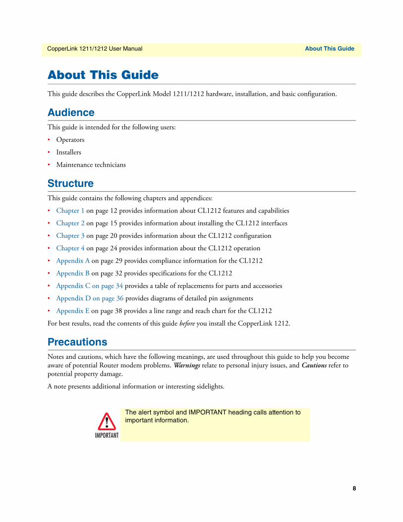
PrecautionsNotes and cautions, which have the following meanings, are used throughout this guide to help you become aware of potential Router modem problems. Warnings relate to personal injury issues, and Cautions refer to potential property damage.
A note presents additional information or interesting sidelights.
IMPORTANT
The alert symbol and IMPORTANT heading calls attention to important information.
8
CopperLink 1211/1212 User Manual About This Guide
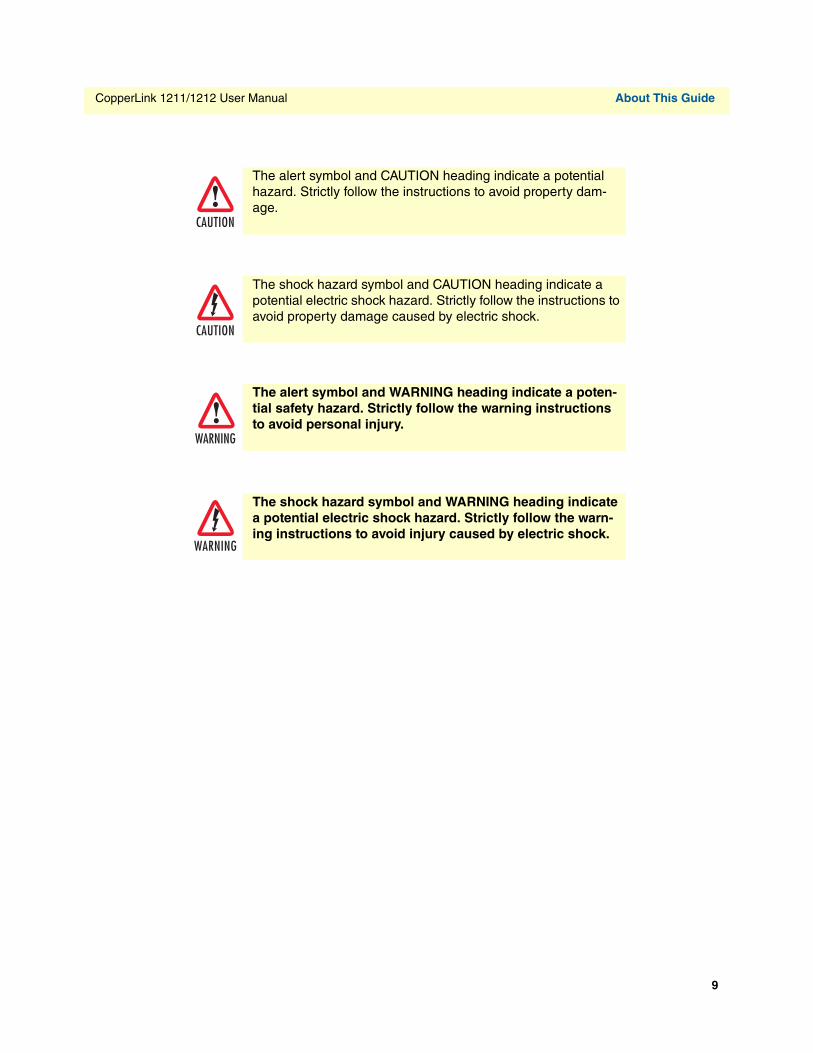
CAUTION
The alert symbol and CAUTION heading indicate a potential hazard. Strictly follow the instructions to avoid property dam-age.
CAUTION
The shock hazard symbol and CAUTION heading indicate a potential electric shock hazard. Strictly follow the instructions to avoid property damage caused by electric shock.
WARNING
The alert symbol and WARNING heading indicate a poten-tial safety hazard. Strictly follow the warning instructions to avoid personal injury.
WARNING
The shock hazard symbol and WARNING heading indicate a potential electric shock hazard. Strictly follow the warn-ing instructions to avoid injury caused by electric shock.
9
CopperLink 1211/1212 User Manual About This Guide
Safety When Working With Electricity
WARNING
• This device contains no user serviceable parts. This device can only be repaired by qualified service person-nel.
• Do not open the device when the power cord is con-nected. For systems without a power switch and without an external power adapter, line voltages are present within the device when the power cord is connected.
• For devices with an external power adapter, the power adapter shall be a listed Limited Power Source. The mains outlet that is utilized to power the device shall be within 10 feet (3 meters) of the device, shall be easily accessible, and protected by a circuit breaker in compli-ance with local regulatory requirements.
• For AC powered devices, ensure that the power cable used meets all applicable standards for the country in which it is to be installed.
• For AC powered devices which have 3 conductor power plugs (L1, L2 & GND or Hot, Neutral & Safety/Protective Ground), the wall outlet (or socket) must have an earth ground.
• For DC powered devices, ensure that the interconnecting cables are rated for proper voltage, current, anticipated temperature, flammability, and mechanical serviceability.
• WAN, LAN & PSTN ports (connections) may have hazard-ous voltages present regardless of whether the device is powered ON or OFF. PSTN relates to interfaces such as telephone lines, FXS, FXO, DSL, xDSL, T1, E1, ISDN, Voice, etc. These are known as “hazardous network volt-ages” and to avoid electric shock use caution when working near these ports. When disconnecting cables for these ports, detach the far end connection first.
• Do not work on the device or connect or disconnect cables during periods of lightning activity.
In accordance with the requirements of council directive 2002/96/EC on Waste of Electrical and Electronic Equipment (WEEE), ensure that at end-of-life you separate this product from other waste and scrap and deliver to the WEEE collection system in your country for recycling.
10
CopperLink 1211/1212 User Manual About This Guide
WARNING
This device contains no user serviceable parts. This device can only be repaired by qualified service personnel.
WARNING
This device is NOT intended nor approved for connection to the PSTN. It is intended only for connection to customer premise equipment.
CAUTION
Electrostatic Discharge (ESD) can damage equipment and impair electrical circuitry. It occurs when electronic printed cir-cuit cards are improperly handled and can result in complete or intermittent failures. Do the following to prevent ESD:
• Always follow ESD prevention procedures when removing and replacing cards.
• Wear an ESD-preventive wrist strap, ensuring that it makes good skin contact. Connect the clip to an unpainted surface of the chassis frame to safely channel unwanted ESD voltages to ground.
• To properly guard against ESD damage and shocks, the wrist strap and cord must operate effectively. If no wrist strap is available, ground yourself by touching the metal part of the chassis.
11

Chapter 1 General information
Chapter contentsFeatures .................................................................................................................................................................13Description............................................................................................................................................................13
12
CopperLink 1211/1212 User Manual 1 • General information
OverviewThank you for purchasing this Patton Electronics product. This product has been thoroughly inspected and tested and is warranted for one year for parts and labor. If any questions or problems arise during installation or use of this product, contact Patton Electronics Technical Support at +(301) 975-1007.
Features• Variable rate CopperLink Ethernet extender - Easy to configure
• Auto-MDIX Ethernet
• Configurable 10/100, Full/Half, and Auto-Negotiating Ethernet
• Extends up to 1 or 2 10/100Base-TX Ethernet beyond 328-foot (100-meter) limitation over a single twisted-pair, Cat 5e/6/7, or coaxial cable
• Variable line rate settings via DIP switch
• Transparent operation
• LED indicators for Power, Line, Local, Remote, Ethernet 0 and 1 (Eth 0 and Eth 1), and Ethernet Link/Activity
DescriptionPatton Electronics CL1212 Ethernet extenders provide high-speed LAN connections between peered Ethernet LANs, remote PCs, or any other network-enabled 10/100Base-T device.
Operating in pairs, one CL1212 is configured as the (L) Local unit located at one end of the LAN extension and the other CL1212 is configured as the (R) Remote unit at the other end. The CL1212 is configured as an L or R via the switch on the bottom of the unit. These units can automatically forward LAN broadcasts, multi-casts, and frames across a 2-wire voice-grade twisted-pair or BNC link. The data is passed transparently (unmodified) through the CL1212. The CL1212s automatically add and delete MAC addresses, only passing packets across the Line link that are meant for the remote peered LAN.
Overview 13
CopperLink 1211/1212 User Manual 1 • General information
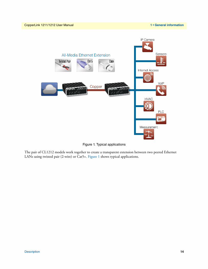
Figure 1. Typical applications
The pair of CL1212 models work together to create a transparent extension between two peered Ethernet LANs using twisted pair (2-wire) or Cat5+. Figure 1 shows typical applications.
Description 14

Chapter 2 Installation
Chapter contentsPlanning the Installation........................................................................................................................................16Connecting the Line Interface ...............................................................................................................................17
Connecting the Line Interface for CL1212 .....................................................................................................17Connecting the Line Interface for CL1212/BNC ............................................................................................18
Connecting the 10/100Base-T Ethernet Interface..................................................................................................18Connecting Power .................................................................................................................................................19
15
CopperLink 1211/1212 User Manual 2 • Installation
Planning the Installation
CAUTION
The Interconnecting cables shall be acceptable for external use and shall be rated for the proper application with respect to volt-age, current, anticipated temperature, flammability, and mechanical serviceability.
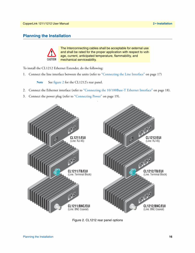
To install the CL1212 Ethernet Extender, do the following:
1. Connect the line interface between the units (refer to “Connecting the Line Interface” on page 17)
Note See figure 2 for the CL1212’s rear panel.
2. Connect the Ethernet interface (refer to “Connecting the 10/100Base-T Ethernet Interface” on page 18).
3. Connect the power plug (refer to “Connecting Power” on page 19).S
Figure 2. CL1212 rear panel options
Ethernet 1
Line
Made in the USA
Ethernet 0Power
Ethernet 1
Line
Made in the USA
Ethernet 0Power
CL1211/BNC/EUI(Line: BNC Coaxial)
CL1211/TB/EUI(Line: Terminal Block)
Ethernet 1
Line
Made in the USA
Power
Ethernet 0
CL1211/EUI(Line: RJ-45)
Line
Made in the USA
Ethernet 1Ethernet 0
Power
CL1212/BNC/EUI(Line: BNC Coaxial)
Line
Made in the USA
Ethernet 1Ethernet 0
Power
CL1212/TB/EUI(Line: Terminal Block)
Line
Made in the USA
Ethernet 1Ethernet 0
Power
CL1212/EUI(Line: RJ-45)
Planning the Installation 16
CopperLink 1211/1212 User Manual 2 • Installation
Connecting the Line Interface
CAUTION
The interconnecting cables shall be acceptable for external use and shall be rated for the proper application with respect to volt-age, current, anticipated temperature, flammability, and mechanical serviceability.
The CL1212 supports communication between two peer Ethernet LAN sites over a distance of up to 10,000 ft (3 km) over 24 AWG (0.5 mm) twisted-pair wire, Cat5+, or 75-ohm BNC.
Note Actual distance and link performance may vary depending on the environ-ment and type/gauge of wire used.
Follow the steps below to connect the CL1212 interfaces.
Note The CL1212 units work in pairs. One of the units must be configured as a (L) Local unit, and the other unit must be configured as a (R) Remote unit.
Connecting the Line Interface for CL12121. To function properly, the two CL1212s must be connected together using twisted-pair, unconditioned,
dry, metal wire, between 19 (0.9mm) and 26 AWG (0.4mm). Leased circuits that run through signal equalization equipment are not acceptable.
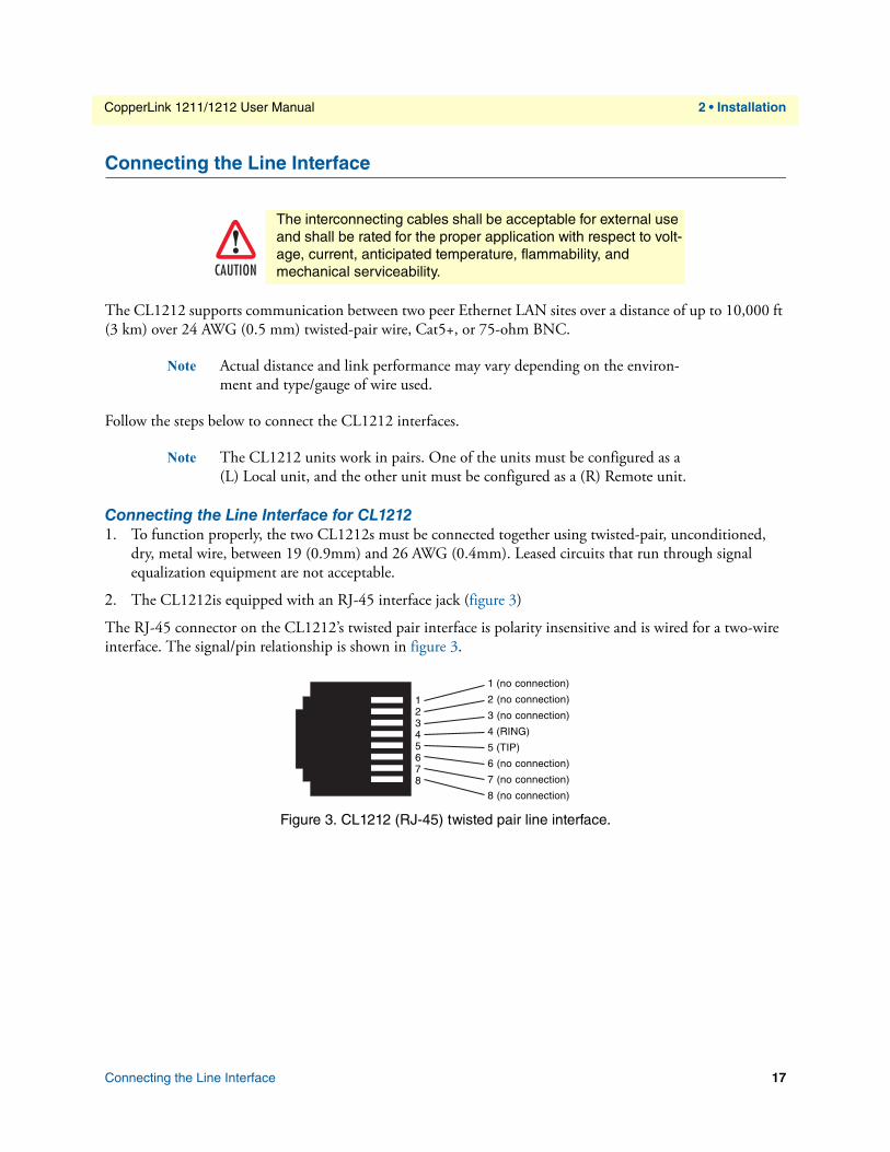
2. The CL1212is equipped with an RJ-45 interface jack (figure 3)
The RJ-45 connector on the CL1212’s twisted pair interface is polarity insensitive and is wired for a two-wire interface. The signal/pin relationship is shown in figure 3.
1 (no connection)
2 (no connection)
3 (no connection)
4 (RING)
5 (TIP)
6 (no connection)
7 (no connection)
8 (no connection)
12345678
Figure 3. CL1212 (RJ-45) twisted pair line interface.
Connecting the Line Interface 17
CopperLink 1211/1212 User Manual 2 • Installation
Line
Made in the USA
Ethernet 1Ethernet 0
Power
Ring Tip
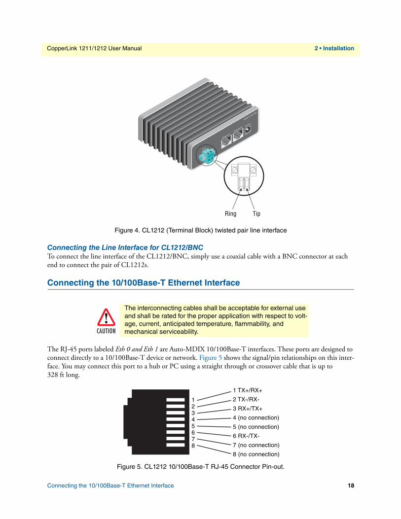
Figure 4. CL1212 (Terminal Block) twisted pair line interface
Connecting the Line Interface for CL1212/BNCTo connect the line interface of the CL1212/BNC, simply use a coaxial cable with a BNC connector at each end to connect the pair of CL1212s.
Connecting the 10/100Base-T Ethernet Interface
CAUTION
The interconnecting cables shall be acceptable for external use and shall be rated for the proper application with respect to volt-age, current, anticipated temperature, flammability, and mechanical serviceability.
The RJ-45 ports labeled Eth 0 and Eth 1 are Auto-MDIX 10/100Base-T interfaces. These ports are designed to connect directly to a 10/100Base-T device or network. Figure 5 shows the signal/pin relationships on this inter-face. You may connect this port to a hub or PC using a straight through or crossover cable that is up to 328 ft long.
Figure 5. CL1212 10/100Base-T RJ-45 Connector Pin-out.
1 TX+/RX+
2 TX-/RX-
3 RX+/TX+
4 (no connection)
5 (no connection)
6 RX-/TX-
7 (no connection)
8 (no connection)
12345678
Connecting the 10/100Base-T Ethernet Interface 18
CopperLink 1211/1212 User Manual 2 • Installation
Connecting Power
CAUTION
The interconnecting cables shall be acceptable for external use and shall be rated for the proper application with respect to volt-age, current, anticipated temperature, flammability, and mechanical serviceability.
The CL1212 does not have a power switch, so it powers up as soon as it is plugged in.
An external AC or DC power supply is available separately. This connection is made via the barrel jack on the rear panel of the CL1212. No configuration is necessary for the power supply.
DC power (supplied via the power supply jack to the CL1212) must meet the following requirements; DC power supplied must be regulated 5 VDC ±5%, 1.0A minimum. Center pin is +5 V. The barrel type plug has 2.5/5.5/10mm I.D./O.D./Shaft Length dimensions.
Connecting Power 19

Chapter 3 Configuration
Chapter contentsIntroduction..........................................................................................................................................................21Accessing the DIP Switches ...................................................................................................................................21Configuring DIP Switch S1...................................................................................................................................22
Switch S1-1: Local/Remote Configuration ......................................................................................................22Switches S1-2 and S1-3: Symmetric/Asymmetric Operation ...........................................................................22Switch S1-5: General Protection (Signal to Noise Ratio) .................................................................................23
20
CopperLink 1211/1212 User Manual 3 • Configuration
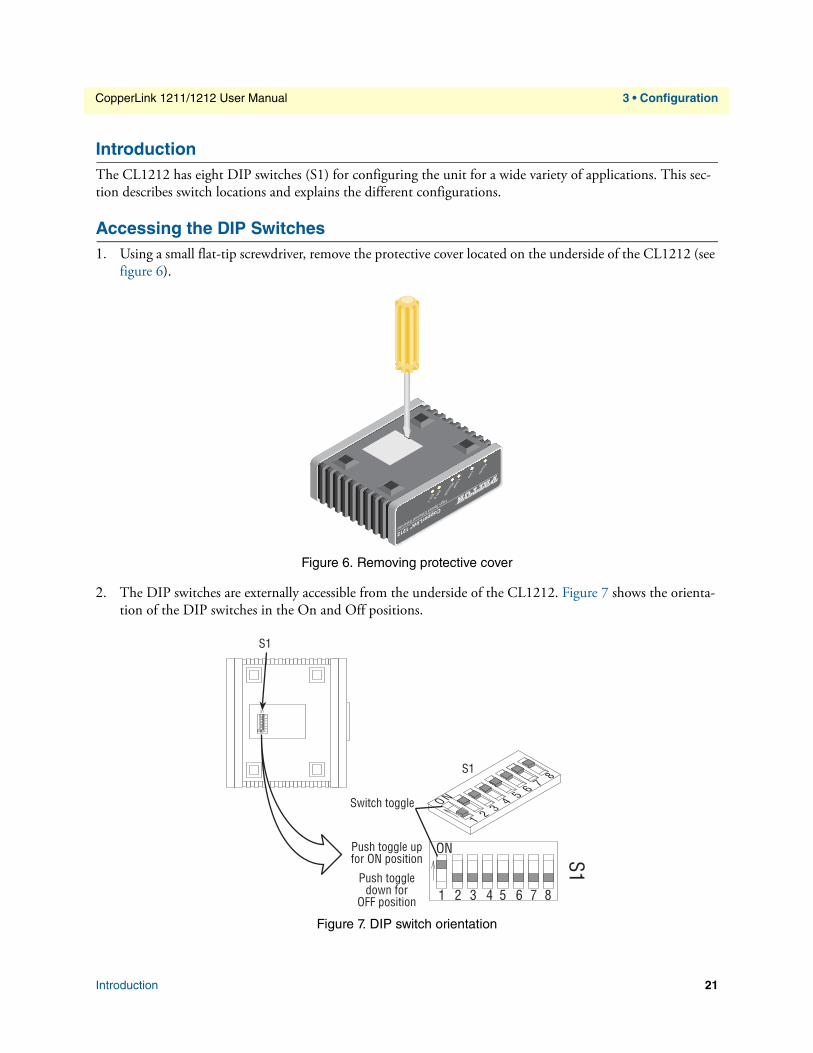
IntroductionThe CL1212 has eight DIP switches (S1) for configuring the unit for a wide variety of applications. This sec-tion describes switch locations and explains the different configurations.
Accessing the DIP Switches1. Using a small flat-tip screwdriver, remove the protective cover located on the underside of the CL1212 (see
figure 6).
Figure 6. Removing protective cover
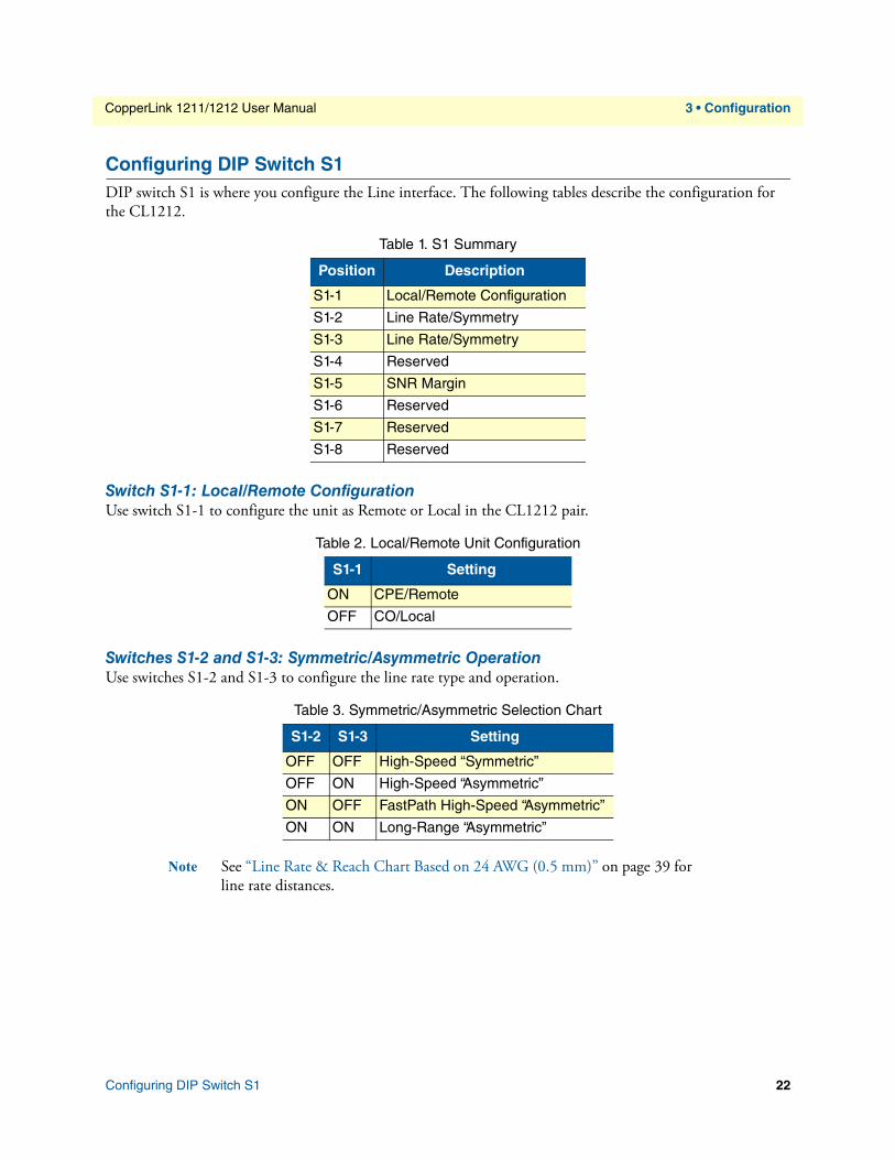
2. The DIP switches are externally accessible from the underside of the CL1212. Figure 7 shows the orienta-tion of the DIP switches in the On and Off positions.
Figure 7. DIP switch orientation
ONPush toggle upfor ON position
Switch toggle
Push toggledown for
OFF position
1 2 3 4O N
S1
S1
S1
5 6 7
12
34
ON
S1
56
7
1 2 3 4 5 6 7 8
8
Introduction 21
CopperLink 1211/1212 User Manual 3 • Configuration
Configuring DIP Switch S1DIP switch S1 is where you configure the Line interface. The following tables describe the configuration for the CL1212.
Table 1. S1 Summary
Position Description
S1-1 Local/Remote Configuration
S1-2 Line Rate/Symmetry
S1-3 Line Rate/Symmetry
S1-4 Reserved
S1-5 SNR Margin
S1-6 Reserved
S1-7 Reserved
S1-8 Reserved
Switch S1-1: Local/Remote ConfigurationUse switch S1-1 to configure the unit as Remote or Local in the CL1212 pair.
Table 2. Local/Remote Unit Configuration
S1-1 Setting
ON CPE/Remote
OFF CO/Local
Switches S1-2 and S1-3: Symmetric/Asymmetric OperationUse switches S1-2 and S1-3 to configure the line rate type and operation.
Table 3. Symmetric/Asymmetric Selection Chart
S1-2 S1-3 Setting
OFF OFF High-Speed “Symmetric”
OFF ON High-Speed “Asymmetric”
ON OFF FastPath High-Speed “Asymmetric”
ON ON Long-Range “Asymmetric”
Note See “Line Rate & Reach Chart Based on 24 AWG (0.5 mm)” on page 39 for line rate distances.
Configuring DIP Switch S1 22

CopperLink 1211/1212 User Manual 3 • Configuration
Switch S1-5: General Protection (Signal to Noise Ratio)Use switch S1-5 to configure line noise protection.
Table 4. Signal to Noise Ratio
S1-5 Setting
ON 6dB
OFF 9dB
• 6dB: Original line noise protection with 6dB SNR
• 9dB: Better line noise protection with SNR up to 9dB
Configuring DIP Switch S1 23

Chapter 4 Operation
Chapter contentsIntroduction..........................................................................................................................................................25Front Panel LED Status Monitors .........................................................................................................................25
24
CopperLink 1211/1212 User Manual 4 • Operation
IntroductionOnce the CL1212s are properly installed, they should operate transparently. No user settings required. This section describes reading the LED status monitors.
Before applying power to the CL1212, please review “Connecting Power” on page 19 to verify that the unit is connected to the appropriate power source.
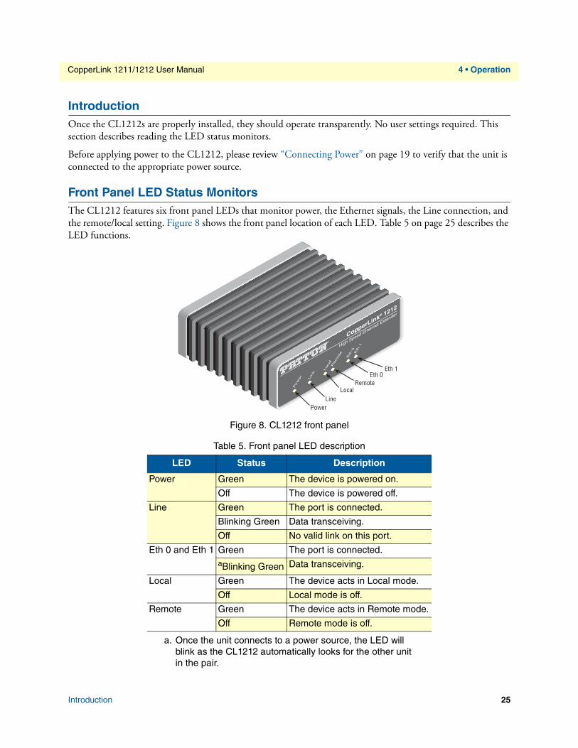
Front Panel LED Status MonitorsThe CL1212 features six front panel LEDs that monitor power, the Ethernet signals, the Line connection, and the remote/local setting. Figure 8 shows the front panel location of each LED. Table 5 on page 25 describes the LED functions.
LineLocal
Remote
Power
Eth 0Eth 1
Figure 8. CL1212 front pan
Table 5. Front panel LED description
LED Status Description
Power Green The device is powered on.
Off The device is powered off.
Line Green The port is connected.
Blinking Green Data transceiving.
Off No valid link on this port.
Eth 0 and Eth 1 Green The port is connected.a
a. Once the unit connects to a power source, the LED will blink as the CL1212 automatically looks for the other unit in the pair.
Blinking Green Data transceiving.
Local Green The device acts in Local mode.
Off Local mode is off.
Remote Green The device acts in Remote mode.
Off Remote mode is off.
el
Introduction 25

Chapter 5 Contacting Patton for assistance
Chapter contentsIntroduction..........................................................................................................................................................27Contact information..............................................................................................................................................27Warranty Service and Returned Merchandise Authorizations (RMAs)...................................................................27
Warranty Coverage .........................................................................................................................................27Out-of-Warranty Service .................................................................................................................................27Returns for Credit ...........................................................................................................................................27
Return-for-Credit Policy ...........................................................................................................................28RMA Numbers ...............................................................................................................................................28Shipping Instructions ......................................................................................................................................28
26
CopperLink 1211/1212 User Manual 5 • Contacting Patton for assistance
IntroductionThis chapter contains the following information:
• “Contact information”—describes how to contact Patton technical support for assistance.
• “Warranty Service and Returned Merchandise Authorizations (RMAs)”—contains information about obtaining a return merchandise authorization (RMA).
Contact informationPatton Electronics offers a wide array of free technical services. If you have questions about any of our other products we recommend you begin your search for answers by using our technical knowledge base. Here, we have gathered together many of the more commonly asked questions and compiled them into a searchable database to help you quickly solve your problems:
• Online support—available at www.patton.com/returns/
• E-mail support—e-mail sent to [email protected] will be answered within 1 business day
• Telephone support—standard telephone support is available five days a week—from 8:00 am to 5:00 pm EST (1300 to 2200 UTC)—by calling +1 (301) 975-1007
Warranty Service and Returned Merchandise Authorizations (RMAs)Patton Electronics is an ISO-9001 certified manufacturer and our products are carefully tested before ship-ment. All of our products are backed by a comprehensive warranty program.
Note If you purchased your equipment from a Patton Electronics reseller, ask your reseller how you should proceed with warranty service. It is often more con-venient for you to work with your local reseller to obtain a replacement. Patton services our products no matter how you acquired them.
Warranty CoverageOur products are under warranty to be free from defects, and we will, at our option, repair or replace the prod-uct should it fail within one year from the first date of shipment. Our warranty is limited to defects in work-manship or materials, and does not cover customer damage, lightning or power surge damage, abuse, or unauthorized modification.
Out-of-Warranty ServicePatton services what we sell, no matter how you acquired it, including malfunctioning products that are no longer under warranty. Our products have a flat fee for repairs. Units damaged by lightning or other catastro-phes may require replacement.
Returns for CreditCustomer satisfaction is important to us, therefore any product may be returned with authorization within 30 days from the shipment date for a full credit of the purchase price. If you have ordered the wrong equipment or you are dissatisfied in any way, please contact us to request an RMA number to accept your return. Patton is not responsible for equipment returned without a Return Authorization.
Introduction 27

CopperLink 1211/1212 User Manual 5 • Contacting Patton for assistance
Return-for-Credit Policy • Less than 30 days: No Charge. Your credit will be issued upon receipt and inspection of the equipment.
• 30 to 60 days: We will add a 20% restocking charge (crediting your account with 80% of the purchase price).
• Over 60 days: Products will be accepted for repairs only.
RMA NumbersRMA numbers are required for all product returns. You can obtain an RMA by doing one of the following:
• Completing a request on the RMA Request page in the Support section at www.patton.com/returns/
• By calling +1 (301) 975-1007 and speaking to a Technical Support Engineer
• By sending an e-mail to [email protected]
All returned units must have the RMA number clearly visible on the outside of the shipping container. Please use the original packing material that the device came in or pack the unit securely to avoid damage during shipping.
Shipping InstructionsThe RMA number should be clearly visible on the address label. Our shipping address is as follows:
Patton Electronics CompanyRMA#: xxxx7622 Rickenbacker Dr.Gaithersburg, MD 20879-4773 USA
Patton will ship the equipment back to you in the same manner you ship it to us. Patton will pay the return shipping costs.
Warranty Service and Returned Merchandise Authorizations (RMAs) 28

Appendix A Compliance Information
Chapter contentsRegulatory Information .........................................................................................................................................30
EMC Directive: ..............................................................................................................................................30Low-Voltage Directive (Safety): ......................................................................................................................30PSTN: ............................................................................................................................................................30
Radio and TV Interference (FCC Part 15) ............................................................................................................30CE Declaration of Conformity ..............................................................................................................................30Authorized European Representative .....................................................................................................................30Service ...................................................................................................................................................................31
29
CopperLink 1211/1212 User Manual A • Compliance Information
Regulatory Information
EMC Directive:• FCC Part 15, Class A
• EN55022, Class A
• EN55024
• EN50581
Low-Voltage Directive (Safety):• IEC/EN60950-1, 2nd Edition
• UL60950-1/CSA C22.2 No. 60950-1
PSTN:• This device is not intended nor approved for connection to the PSTN
Radio and TV Interference (FCC Part 15)This device generates and uses radio frequency energy, and if not installed and used properly-that is, in strict accordance with the manufacturer’s instructions-may cause interference to radio and television reception. The device has been tested and found to comply with the limits for a Class A computing device in accordance with specifications in Subpart B of Part 15 of FCC rules, which are designed to provide reasonable protection from such interference in a commercial installation. However, there is no guarantee that interference will not occur in a particular installation. If the device does cause interference to radio or television reception, which can be determined by disconnecting the unit, the user is encouraged to try to correct the interference by one or more of the following measures: moving the computing equipment away from the receiver, re-orienting the receiving antenna and/or plugging the receiving equipment into a different AC outlet (such that the computing equip-ment and receiver are on different branches).
CE Declaration of ConformityThis device is in compliance with the essential requirements and other relevant provisions of Directive 2004/108/EC relating to electromagnetic compatibility and Directive 2006/95/EC relating to electrical equipment designed for use within certain voltage limits. The Declaration of Conformity may be obtained from Patton Electronics, Inc at www.patton.com/certifications.
The safety advice in the documentation accompanying this device shall be obeyed. The conformity to the above directive is indicated by CE mark on the device.
Authorized European RepresentativeD R M GreenEuropean Compliance Services LtdGreyfriars CourtParadise SquareOxford, OX1 1BE, UK
Regulatory Information 30

CopperLink 1211/1212 User Manual A • Compliance Information
ServiceAll warranty and non-warranty repairs must be returned freight prepaid and insured to Patton Electronics. All returns must have a Return Materials Authorization number on the outside of the shipping container. This number may be obtained from Patton Electronics Technical Services at:
• Tel: +1 (301) 975-1007
• Email: [email protected]
• URL: http://www.patton.com
Packages received without an RMA number will not be accepted.
Service 31
Appendix B Specifications
Chapter contentsLine Connector .....................................................................................................................................................33LAN Connectors ...................................................................................................................................................33Transmission Line .................................................................................................................................................33LED Status Indicators ...........................................................................................................................................33Power Supply ........................................................................................................................................................33
External AC option: ........................................................................................................................................33Physical .................................................................................................................................................................33
Operating Temperature Range ........................................................................................................................33Humidity ........................................................................................................................................................33Dimensions .....................................................................................................................................................33
32
CopperLink 1211/1212 User Manual B • Specifications
Line Connector• RJ-45, Terminal Block, or BNC Coaxial
LAN Connectors• 2 RJ-45, 10/100Base-T, IEEE 802.3 Ethernet
Transmission LineTwo-wire unconditioned twisted pair
LED Status Indicators• Power (Green)
• Line (Green)
• Local (Green)
• Remote (Green)
• Ethernet (Green when linked; flashing green when transceiving data)
Power Supply
External AC option:• AC: 120 VAC, 220 VAC, and UI (120–240 VAC)
• DC: 12 VDC, 24 VDC and 48 VDC , 5 VDC
• Power consumption: 1 A at 5 VDC
Physical
Operating Temperature Range32 to 122°F (0 to 50°C)For extended temperature option see CL1214E (http://www.patton.com/products/product_detail.asp?id=486)
HumidityUp to 90% non-condensing.
Dimensions4.13 W x 1.5 H x 3.75 D in. (105 W x 38.1 H x 95.3 D mm)
Line Connector 33

Appendix C Factory Replacement Parts and Accessories
Chapter contentsCL1211/CL1212 Factory Replacement Parts and Accessories ...............................................................................35
34
CopperLink 1211/1212 User Manual C • Factory Replacement Parts and Accessories
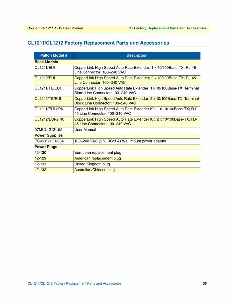
CL1211/CL1212 Factory Replacement Parts and Accessories
Patton Model # Description
Base Models
CL1211/EUI CopperLink High Speed Auto Rate Extender; 1 x 10/100Base-TX; RJ-45 Line Connector; 100–240 VAC
CL1212/EUI CopperLink High Speed Auto Rate Extender; 2 x 10/100Base-TX; RJ-45 Line Connector; 100–240 VAC
CL1211/TB/EUI CopperLink High Speed Auto Rate Extender; 1 x 10/100Base-TX; Terminal Block Line Connector; 100–240 VAC
CL1212/TB/EUI CopperLink High Speed Auto Rate Extender; 2 x 10/100Base-TX; Terminal Block Line Connector; 100–240 VAC
CL1211/EUI-2PK CopperLink High Speed Auto Rate Extender Kit; 1 x 10/100Base-TX; RJ-45 Line Connector; 100–240 VAC
CL1212/EUI-2PK CopperLink High Speed Auto Rate Extender Kit; 2 x 10/100Base-TX; RJ-45 Line Connector; 100–240 VAC
07MCL1212-UM User Manual
Power Supplies
PS-03671H1-004 100–240 VAC (5 V, DC/3 A) Wall mount power adapter
Power Plugs
12-130 European replacement plug
12-129 American replacement plug
12-131 United Kingdom plug
12-132 Australian/Chinese plug
CL1211/CL1212 Factory Replacement Parts and Accessories 35

Appendix D Interface Pin Assignment
Chapter contents10/100Base-T Interface .........................................................................................................................................37
RJ-45 ..............................................................................................................................................................37Line Interface ........................................................................................................................................................37
RJ-45 ..............................................................................................................................................................37Terminal Block ...............................................................................................................................................37
36
CopperLink 1211/1212 User Manual D • Interface Pin Assignment
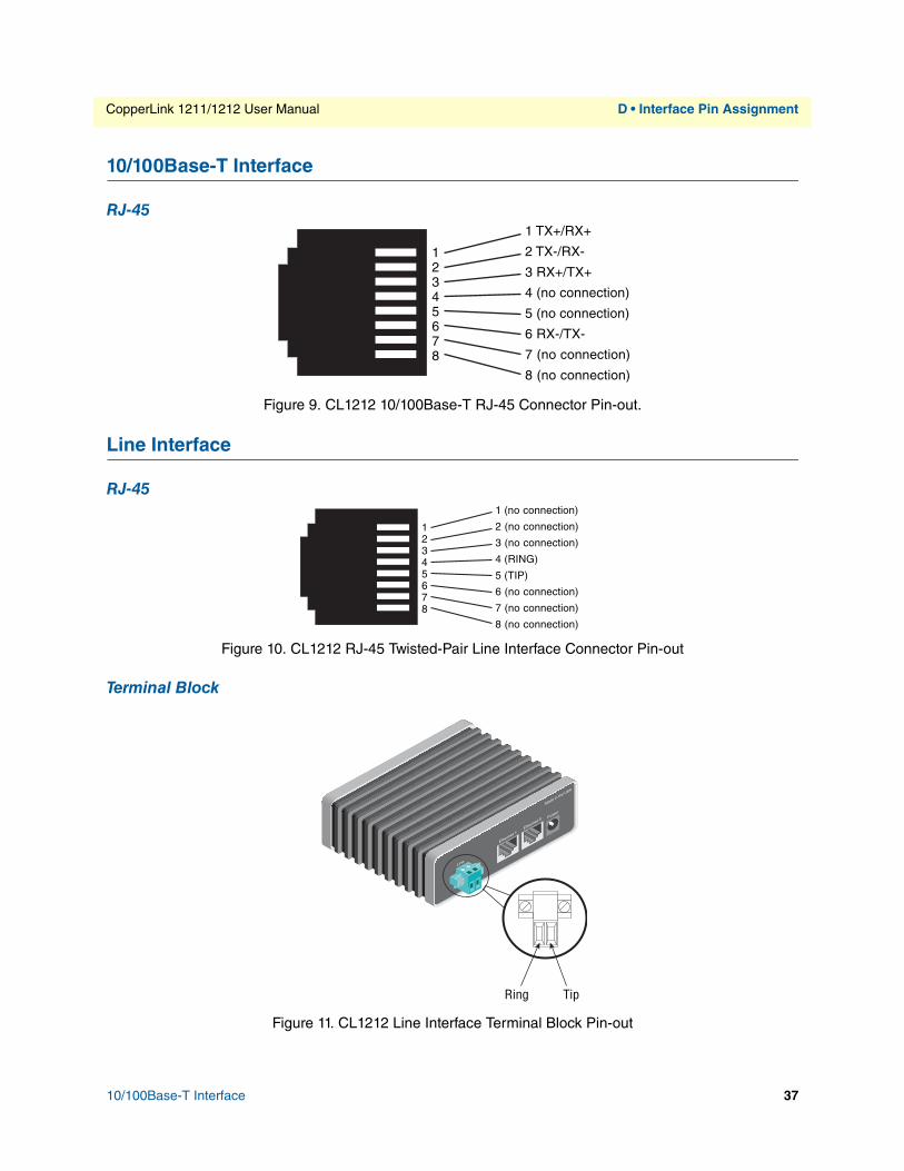
10/100Base-T Interface
RJ-451 TX+/RX+
2 TX-/RX-
3 RX+/TX+
4 (no connection)
5 (no connection)
6 RX-/TX-
7 (no connection)
8 (no connection)
12345678
Figure 9. CL1212 10/100Base-T RJ-45 Connector Pin-out.
Line Interface
RJ-451 (no connection)
2 (no connection)
3 (no connection)
4 (RING)
5 (TIP)
6 (no connection)
7 (no connection)
8 (no connection)
12345678
Figure 10. CL1212 RJ-45 Twisted-Pair Line Interface Connector Pin-out
Terminal Block
Line
Made in the USA
Ethernet 1Ethernet 0
Power
Ring Tip
Figure 11. CL1212 Line Interface Terminal Block Pin-out
10/100Base-T Interface 37

Appendix E Line Rate & Reach Chart
Chapter contentsLine Rate & Reach Chart Based on 24 AWG (0.5 mm) ........................................................................................39
38
CopperLink 1211/1212 User Manual E • Line Rate & Reach Chart
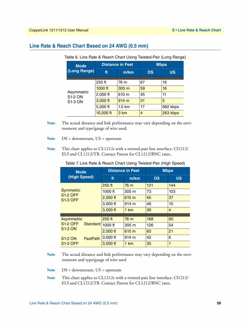
Table 6. Line Rate & Reach Chart Using Twisted-Pair (Long Range)
Mode(Long Range)
Distance in Feet Mbps
ft m/km DS US
AsymmetricS1-2 ONS1-3 ON
250 ft 76 m 67 16
1000 ft 305 m 59 16
2,000 ft 610 m 45 11
3,000 ft 914 m 31 5
5,000 ft 1.5 km 17 682 kbps
10,000 ft 3 km 4 263 kbps
Line Rate & Reach Chart Based on 24 AWG (0.5 mm)
Note The actual distance and link performance may vary depending on the envi-ronment and type/gauge of wire used.
Note DS = downstream, US = upstream
Note This chart applies to CL1212s with a twisted-pair line interface: Cl1212/ EUl and CL1212/TB. Contact Patton for CL1212/BNC rates..
Table 7. Line Rate & Reach Chart Using Twisted-Pair (High Speed)
Mode(High Speed)
Distance in Feet Mbps
ft m/km DS US
SymmetricS1-2 OFFS1-3 OFF
250 ft 76 m 121 144
1000 ft 305 m 73 103
2,000 ft 610 m 45 37
3,000 ft 914 m 46 10
3,500 ft 1 km 30 4
AsymmetricS1-2 OFFS1-3 ONS1-2 ONS1-3 OFF
Standard
FastPath
250 ft 76 m 168 95
1000 ft 305 m 126 54
2,000 ft 610 m 60 21
3,000 ft 914 m 42 6
3,500 ft 1 km 35 1
Note The actual distance and link performance may vary depending on the envi-ronment and type/gauge of wire used
Note DS = downstream, US = upstream
Note This chart applies to CL1212s with a twisted-pair line interface: Cl1212/ EUl and CL1212/TB. Contact Patton for CL1212/BNC rates.
Line Rate & Reach Chart Based on 24 AWG (0.5 mm) 39