Embed Size (px)
Citation preview
Part# 07M2168-UMDoc# 05816U2-002Rev. ARevised 10/23/06
An ISO-9001CertifiedCompany
USER MANUALCopperLink™ Ethernet ExtendersModel 2168 and 2158
SALES OFFICE(301) 975-1000TECHNICAL SUPPORT(301) 975-1007
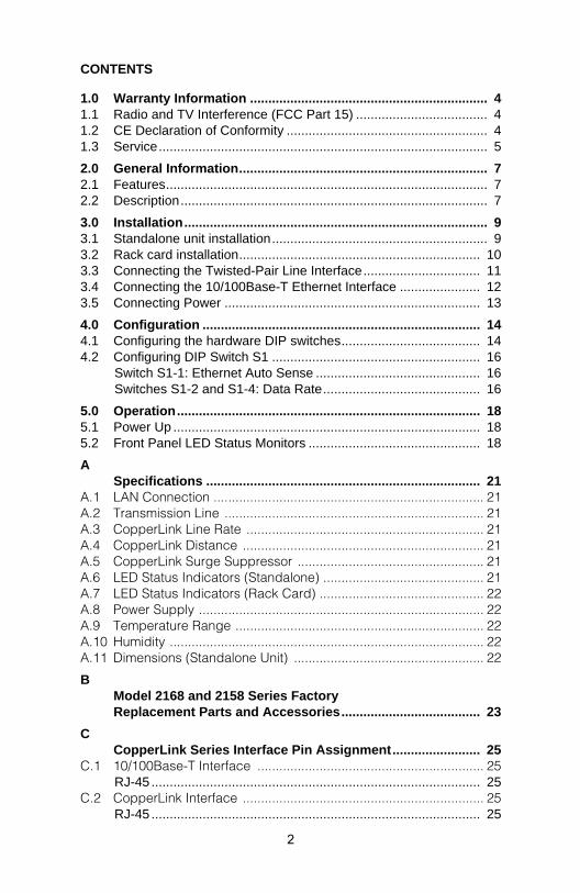
CONTENTS
1.0 Warranty Information ................................................................. 41.1 Radio and TV Interference (FCC Part 15) .................................... 41.2 CE Declaration of Conformity ....................................................... 41.3 Service.......................................................................................... 5
2.0 General Information.................................................................... 72.1 Features........................................................................................ 72.2 Description.................................................................................... 7
3.0 Installation................................................................................... 93.1 Standalone unit installation........................................................... 93.2 Rack card installation.................................................................. 103.3 Connecting the Twisted-Pair Line Interface................................ 113.4 Connecting the 10/100Base-T Ethernet Interface ...................... 123.5 Connecting Power ...................................................................... 13
4.0 Configuration ............................................................................ 144.1 Configuring the hardware DIP switches...................................... 144.2 Configuring DIP Switch S1 ......................................................... 16
Switch S1-1: Ethernet Auto Sense ............................................. 16Switches S1-2 and S1-4: Data Rate........................................... 16
5.0 Operation................................................................................... 185.1 Power Up .................................................................................... 185.2 Front Panel LED Status Monitors ............................................... 18
ASpecifications ........................................................................... 21
A.1 LAN Connection .......................................................................... 21A.2 Transmission Line ....................................................................... 21A.3 CopperLink Line Rate ................................................................. 21A.4 CopperLink Distance .................................................................. 21A.5 CopperLink Surge Suppressor ................................................... 21A.6 LED Status Indicators (Standalone) ............................................ 21A.7 LED Status Indicators (Rack Card) ............................................. 22A.8 Power Supply .............................................................................. 22A.9 Temperature Range .................................................................... 22A.10 Humidity ...................................................................................... 22A.11 Dimensions (Standalone Unit) .................................................... 22
BModel 2168 and 2158 Series Factory Replacement Parts and Accessories...................................... 23
CCopperLink Series Interface Pin Assignment........................ 25
C.1 10/100Base-T Interface .............................................................. 25RJ-45 .......................................................................................... 25
C.2 CopperLink Interface .................................................................. 25RJ-45 .......................................................................................... 25
2

Terminal Block............................................................................ 25
DDistance Chart, Based on 24 AWG (0.5 MM) .......................... 26
3
1.0 WARRANTY INFORMATION
Patton Electronics warrants all CopperLink Ethernet Extender compo-nents to be free from defects, and will—at our option—repair or replace the product should it fail within one year from the first date of the ship-ment.
This warranty is limited to defects in workmanship or materials, and does not cover customer damage, abuse or unauthorized modification. If this product fails or does not performs as warranted, your sole recourse shall be repair or replacement as described above. Under no condition shall Patton Electronics be liable for any damages incurred by the use of this product. These damages include, but are not limited to, the following: lost profits, lost savings and incidental or consequential damages arising from the use of or inability to use this product. Patton Electronics spe-cifically disclaims all other warranties, expressed or implied, and the installation or use of this product shall be deemed an acceptance of these terms by the user.
Note Conformity documents of all Patton products can be viewed online at www.patton.com under the appropriate product page.
1.1 RADIO AND TV INTERFERENCE (FCC PART 15)
This equipment generates and uses radio frequency energy, and if not installed and used properly—that is, in strict accordance with the manu-facturer's instructions—may cause interference to radio and television reception. This equipment has been tested and found to comply with the limits for a Class A computing device in accordance with the specifica-tions in Subpart B of Part 15 of FCC rules, which are designed to provide reasonable protection from such interference in a commercial installa-tion. However, there is no guarantee that interference will not occur in a particular installation. If the equipment causes interference to radio or television reception, which can be determined by disconnecting the cables, try to correct the interference by one or more of the following measures: moving the computing equipment away from the receiver, re-orienting the receiving antenna, and/or plugging the receiving equipment into a different AC outlet (such that the computing equipment and receiver are on different branches).
1.2 CE DECLARATION OF CONFORMITY
We certify that the apparatus identified in this document conforms to the requirements of Council Directive 1999/5/EC on the approximation of the laws of the member states relating to Radio and Telecommunication Ter-minal Equipment and the mutual recognition of their conformity.
4
The safety advice in the documentation accompanying this product shall be obeyed. The conformity to the above directive is indicated by the CE sign on the device.
1.3 SERVICE
All warranty and non-warranty repairs must be returned freight prepaid and insured to Patton Electronics. All returns must have a Return Materi-als Authorization number on the outside of the shipping container. This number may be obtained from Patton Electronics Technical Services at:
• Tel: +1 (301) 975-1007
• Email: [email protected]
• URL: http://www.patton.com
Note Packages received without an RMA number will not be
accepted.
WARNING
This device is NOT intended nor approved for connec-tion to the PSTN. It is intended only for connection to customer premise equipment.
WARNING
• This device contains no user serviceable parts. The equipment shall be returned to Patton Electronics for repairs, or repaired by qualified service personnel.
• The external power adapter shall be a listed Limited Power Source. Ensure that the power cable used meets all applicable standards for the country in which it is to be installed, and that it is connected to a wall outlet which has earth ground. The mains out-let that is utilized to power the devise shall be within 10 feet (3 meters) of the device, shall be easily accessible, and protected by a circuit breaker.
• Do not work on the system or connect or disconnect cables during periods of lightning activity.
5
WARNING
The Interconnecting cables shall be acceptable for external use and shall be rated for the proper applica-tion with respect to voltage, current, anticipated tem-perature, flammability, and mechanical serviceability
In accordance with the requirements of council direc-tive 2002/96/EC on Waste of Electrical and Electronic Equipment (WEEE), ensure that at end-of-life you sepa-rate this product from other waste and scrap and deliver to the WEEE collection system in your country for recy-cling.
6
2.0 GENERAL INFORMATION
Thank you for your purchase of this Patton Electronics product. This product has been thoroughly inspected and tested and is warranted for one year for parts and labor. If any questions or problems arise during installation or use of this product, contact Patton Electronics Technical Support at +1 (301) 975-1007.
2.1 FEATURES
• Easy to install standalone CopperLink Ethernet Extenders (no configu-ration required)
• Auto MDIX Ethernet
• Auto-sensing full or half-duplex Ethernet
• Auto-sensing 10/100Base-TX
• Extends network connections up to 6,000 ft (1.83 km) over 2-wire 24-AWG unconditioned lines
• Switch selectable line rates up to 16.67 Mbps
• 7 symmetric or asymmetric settings via DIP switch
• Transparent operation
• LED indicators for Power, Ethernet Link & Activity, CopperLink link & Quality of Line (QOL)
• Surge suppression up to 20 kA (8/20 µs)
• Available in rack-mount or standalone configurations
• Made in the USA
2.2 DESCRIPTION
The Patton Electronics CopperLink/L and CopperLink/R Ethernet Extenders provide high-speed LAN connections between peered Ether-net LANs, remote PCs, or any other network enabled 10/100Base-T device.
Operating in pairs, a CopperLink/L (local) located at one end of the LAN extension and a CopperLink/R (remote) at the other end, these units can automatically forward LAN broadcasts, multicasts, and frames across a 2-wire voice-grade twisted-pair link. The data is passed transparently (unmodified) through the CopperLink Ethernet Extenders. The CopperLink
7
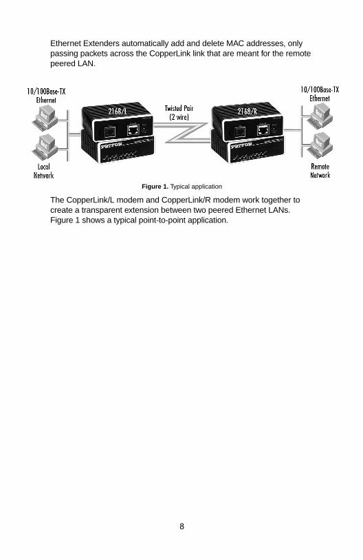
Ethernet Extenders automatically add and delete MAC addresses, only passing packets across the CopperLink link that are meant for the remote peered LAN.
Figure 1. Typical application
The CopperLink/L modem and CopperLink/R modem work together to create a transparent extension between two peered Ethernet LANs. Figure 1 shows a typical point-to-point application.
8
C
3.0 INSTALLATION
Because the CopperLink Ethernet Extender requires no configuration, it can be installed quickly. If you are installing a standalone unit, refer to section 3.1 “Standalone unit installation”. Otherwise, refer to section 3.2 “Rack card installation”.
Note If asymmetric transmission or line rates other than 12.5 Mbps are required , refer to section 4.0, “Configuration” on page 14.
3.1 STANDALONE UNIT INSTALLATION
Do the following:
1. Connect the line interface between the units (refer to section 3.3, “Connecting the Twisted-Pair Line Interface” on page 11)
Note See Figure 2 for the standalone unit’s rear panel arrangements.
2. Connect the Ethernet interface (refer to section 3.4, “Connecting the 10/100Base-T Ethernet Interface” on page 12).
3. Connect the power plug (refer to section 3.5, “Connecting Power” on page 13).
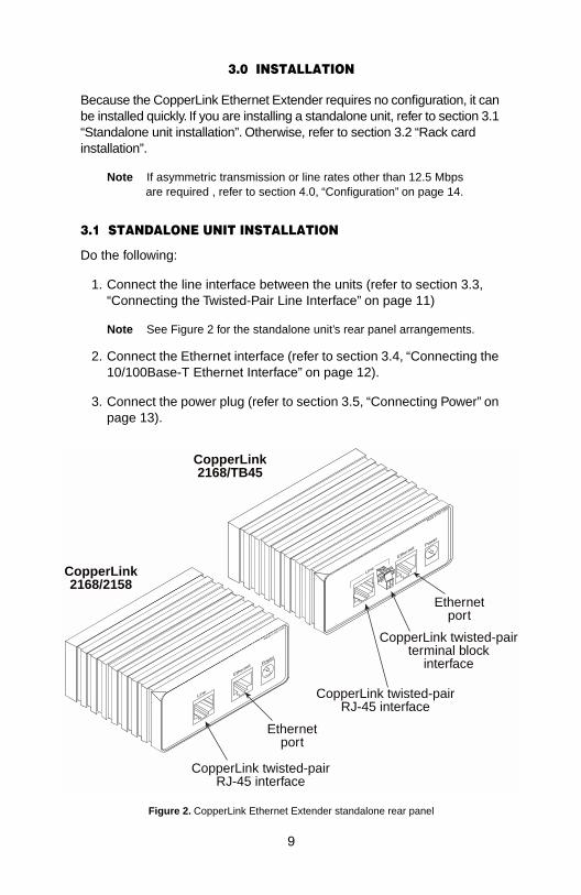
Figure 2. CopperLink Ethernet Extender standalone rear panel
Power
Made in th
e USA
opperLink2168/2158
Line
Ethernetport
Ethernet
Power
Made in th
e USA
CopperLink2168/TB45
CopperLink twisted-pairterminal block
interface
Ethernetport
CopperLink twisted-pairRJ-45 interface
CopperLink twisted-pairRJ-45 interface
Line
Ethernet
9
3.2 RACK CARD INSTALLATION
The CopperLink Ethernet Extender rack card comprised a front card and a rear card.Do the following to install the cards into the rack chassis:
1. Slide the rear card into the back of the chassis along the metal rails.
2. Secure the rear card using the supplied metal screws.
3. Slide the front card into the chassis until you feel resistance as the front card engages the rear card. When that happens, gently push the front card forward until it is fully seated in the card-edge recepta-cle of the rear card (it should click into place).
4. Secure the front card using the captive fasteners.
Note The Model 1001R14 chassis supports “hot swapping” of cards, so it is not necessary to power down the rack when you install or remove a CopperLink Ethernet Extender rack card.
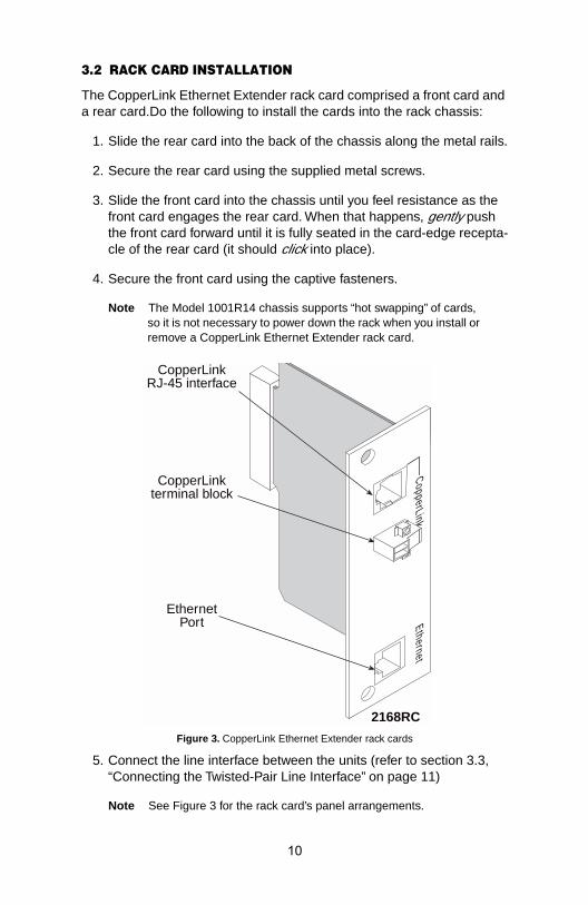
Figure 3. CopperLink Ethernet Extender rack cards
5. Connect the line interface between the units (refer to section 3.3, “Connecting the Twisted-Pair Line Interface” on page 11)
Note See Figure 3 for the rack card’s panel arrangements.
2168RC
CopperLinkRJ-45 interface
CopperLinkterminal block
CopperLink
EthernetPort Ethernet
10
6. Connect the Ethernet interface (refer to section 3.4, “Connecting the 10/100Base-T Ethernet Interface” on page 12).
3.3 CONNECTING THE TWISTED-PAIR LINE INTERFACE
The CopperLink Ethernet Extender supports communication between two peer Ethernet LAN sites over a distance of up to 6,000 ft (1.83 km) over 24 AWG (0.5 mm) twisted-pair wire.
Note Actual distance and link performance may vary depending on the environment and type/gauge of wire used.
Follow the steps below to connect the CopperLink Ethernet Extenders interfaces.
Note The CopperLink units work in pairs. One of the CopperLink units must be an L (local), and the other unit must be an R (remote). It does not matter which end is the L and which is the R. The link is always initiated by the R. As long as the L is powered on, the R can establish a link by being powered on or by having its power reset.
1. To function properly, the two CopperLink Ethernet Extenders must be connected together using twisted-pair, unconditioned, dry, metal wire, between 19 (0.9mm) and 26 AWG (0.4mm). Leased circuits that run through signal equalization equipment are not acceptable.
2. The CopperLink Ethernet Extenders are equipped with two interface jacks that can be used on the CopperLink interface, an RJ-45 or a ter-minal block. These CopperLink interfaces are a two-wire interface. Observe the signal/pin relationships on the CopperLink Ethernet Extender's CopperLink interface jacks.
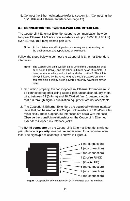
The RJ-45 connector on the CopperLink Ethernet Extender's twisted pair interface is polarity insensitive and is wired for a two-wire inter-face. The signal/pin relationship is shown in Figure 4.
Figure 4. CopperLink Ethernet Extender (RJ-45) twisted pair line interface.
1 (no connection)
2 (no connection)
3 (no connection)
4 (2-Wire RING)
5 (2-Wire TIP)
6 (no connection)
7 (no connection)
8 (no connection)
12345678
11
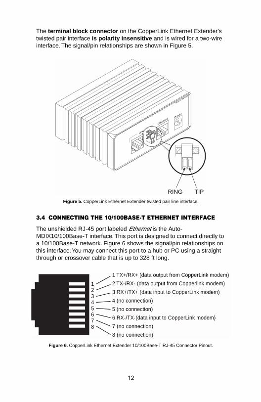
The terminal block connector on the CopperLink Ethernet Extender's twisted pair interface is polarity insensitive and is wired for a two-wire interface. The signal/pin relationships are shown in Figure 5.
Figure 5. CopperLink Ethernet Extender twisted pair line interface.
3.4 CONNECTING THE 10/100BASE-T ETHERNET INTERFACE
The unshielded RJ-45 port labeled Ethernet is the Auto-MDIX10/100Base-T interface. This port is designed to connect directly to a 10/100Base-T network. Figure 6 shows the signal/pin relationships on this interface. You may connect this port to a hub or PC using a straight through or crossover cable that is up to 328 ft long.
Figure 6. CopperLink Ethernet Extender 10/100Base-T RJ-45 Connector Pinout.
Power
Made in th
e USA
Ethernet
Line
RING TIP
1 TX+/RX+ (data output from CopperLink modem)
2 TX-/RX- (data output from Copperlink modem)
3 RX+/TX+ (data input to CopperLink modem)
4 (no connection)
5 (no connection)
6 RX-/TX-(data input to CopperLink modem)
7 (no connection)
8 (no connection)
12345678
12
3.5 CONNECTING POWER
An external AC or DC power supply is available separately. This connec-tion is made via the barrel jack on the rear panel of the CopperLink Ethernet Extender. No configuration is necessary for the power supply (See Appendix B for domestic and international power supply and cord options).
DC power (supplied via the power supply jack to the CopperLink Ether-net Extender) must meet the following requirements; DC power supplied must be regulated +5VDC ±5%, 1.0A minimum. Center pin is +5V. The barrel type plug has a 2.5/5.5/10mm I.D./O.D./Shaft Length dimensions.
The CopperLink Ethernet Extender does not have a power switch, so it powers up as soon as it is plugged in.
WARNING
There are no user-serviceable parts in the Copper-Link Ethernet Extender.Fuse replacement should only be performed by qualified service personnel. Contact Patton Electronics Technical support at (301) 975-1007 for more information.
13
4.0 CONFIGURATION
The CopperLink Model 2168r has eight DIP switches for configuring the unit for a wide variety of applications. This section describes switch loca-tions and explains the different configurations. The Model 2158 does not include dip switches.
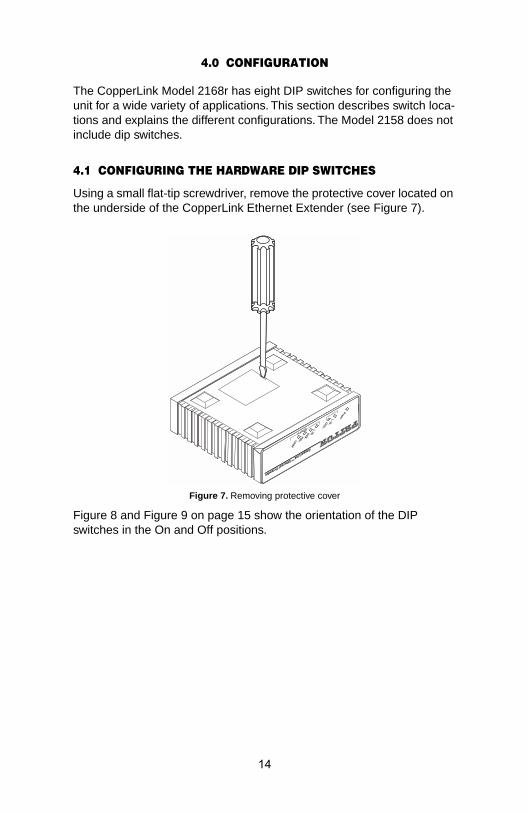
4.1 CONFIGURING THE HARDWARE DIP SWITCHES
Using a small flat-tip screwdriver, remove the protective cover located on the underside of the CopperLink Ethernet Extender (see Figure 7).
Figure 7. Removing protective cover
Figure 8 and Figure 9 on page 15 show the orientation of the DIP switches in the On and Off positions.
CopperLink™ Ethernet Extender
CopperLink
14
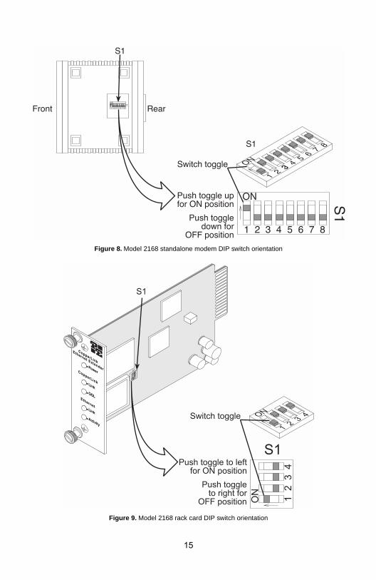
Figure 8. Model 2168 standalone modem DIP switch orientation
Figure 9. Model 2168 rack card DIP switch orientation
15
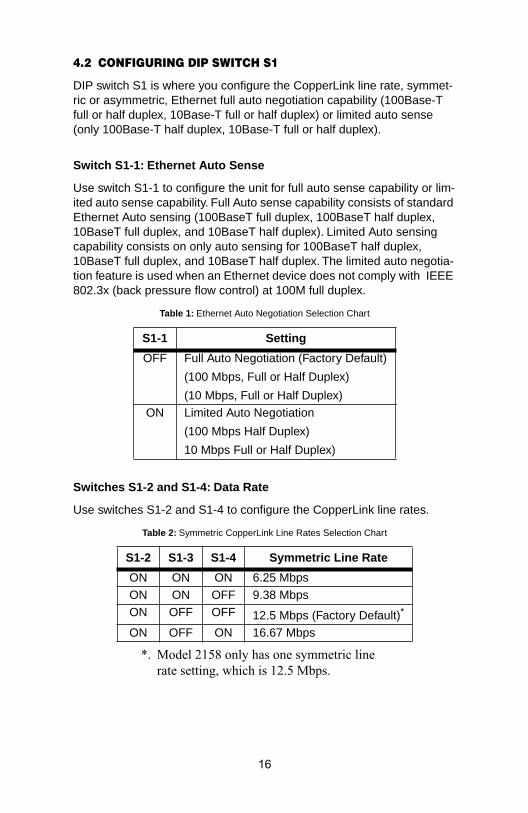
4.2 CONFIGURING DIP SWITCH S1
DIP switch S1 is where you configure the CopperLink line rate, symmet-ric or asymmetric, Ethernet full auto negotiation capability (100Base-T full or half duplex, 10Base-T full or half duplex) or limited auto sense (only 100Base-T half duplex, 10Base-T full or half duplex).
Switch S1-1: Ethernet Auto Sense
Use switch S1-1 to configure the unit for full auto sense capability or lim-ited auto sense capability. Full Auto sense capability consists of standard Ethernet Auto sensing (100BaseT full duplex, 100BaseT half duplex, 10BaseT full duplex, and 10BaseT half duplex). Limited Auto sensing capability consists on only auto sensing for 100BaseT half duplex, 10BaseT full duplex, and 10BaseT half duplex. The limited auto negotia-tion feature is used when an Ethernet device does not comply with IEEE 802.3x (back pressure flow control) at 100M full duplex.
Switches S1-2 and S1-4: Data Rate
Use switches S1-2 and S1-4 to configure the CopperLink line rates.
Table 1: Ethernet Auto Negotiation Selection Chart
S1-1 Setting
OFF Full Auto Negotiation (Factory Default)
(100 Mbps, Full or Half Duplex)
(10 Mbps, Full or Half Duplex)ON Limited Auto Negotiation
(100 Mbps Half Duplex)
10 Mbps Full or Half Duplex)
Table 2: Symmetric CopperLink Line Rates Selection Chart
S1-2 S1-3 S1-4 Symmetric Line Rate
ON ON ON 6.25 MbpsON ON OFF 9.38 MbpsON OFF OFF 12.5 Mbps (Factory Default)*
*. Model 2158 only has one symmetric line rate setting, which is 12.5 Mbps.
ON OFF ON 16.67 Mbps
16
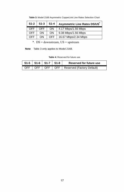
Note Table 3 only applies to Model 2168.
Table 3: Model 2168 Asymmetric CopperLink Line Rates Selection Chart
S1-2 S1-3 S1-4 Asymmetric Line Rates DS/US *
*. DS = downstream, US = upstream
OFF OFF ON 4.17 Mbps/1.56 Mbps OFF ON ON 9.38 Mbps/1.56 MbpsOFF ON OFF 16.67 Mbps/2.34 Mbps
Table 4: Reserved for future use
S1-5 S1-6 S1-7 S1-8 Reserved for future use
OFF OFF OFF OFF Reserved (Factory Default)
17
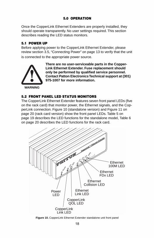
5.0 OPERATION
Once the CopperLink Ethernet Extenders are properly installed, they should operate transparently. No user settings required. This section describes reading the LED status monitors.
5.1 POWER UPBefore applying power to the CopperLink Ethernet Extender, please review section 3.5, “Connecting Power” on page 13 to verify that the unit is connected to the appropriate power source.
5.2 FRONT PANEL LED STATUS MONITORSThe CopperLink Ethernet Extender features seven front panel LEDs (five on the rack card) that monitor power, the Ethernet signals, and the Cop-perLink connection. Figure 10 (standalone version) and Figure 11 on page 20 (rack card version) show the front panel LEDs. Table 5 on page 19 describes the LED functions for the standalone model, Table 6 on page 20 describes the LED functions for the rack card.
Figure 10. CopperLink Ethernet Extender standalone unit front panel
WARNING
There are no user-serviceable parts in the Copper-Link Ethernet Extender. Fuse replacement should only be performed by qualified service personnel. Contact Patton Electronics Technical support at (301) 975-1007 for more information.
PowerLED
CopperLinkLink LED
EthernetLink LED
EthernetCollision LED
EthernetFDx LED
CopperLinkQOL LED
Ethernet100M LED
CopperLink™ Ethernet Extender
CopperLink
18
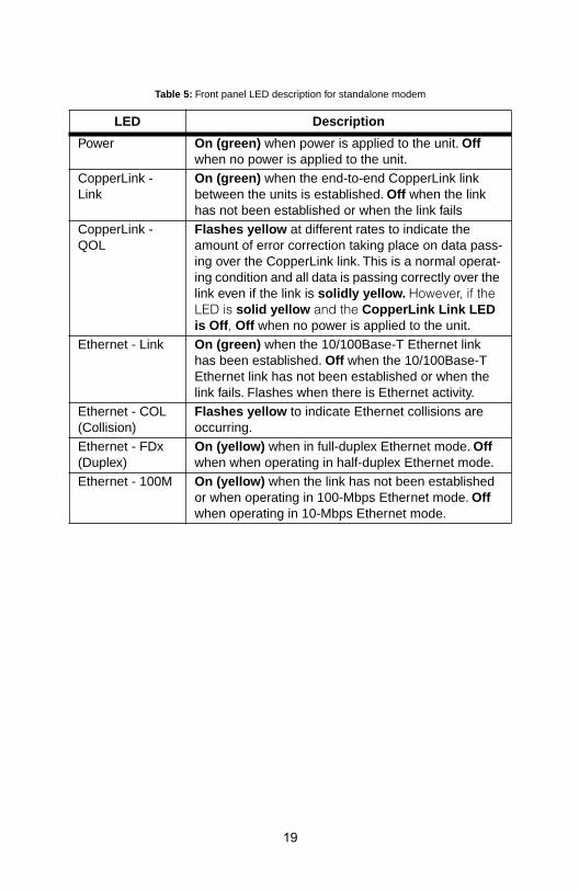
Table 5: Front panel LED description for standalone modem
LED Description
Power On (green) when power is applied to the unit. Off when no power is applied to the unit.
CopperLink - Link
On (green) when the end-to-end CopperLink link between the units is established. Off when the link has not been established or when the link fails
CopperLink - QOL
Flashes yellow at different rates to indicate the amount of error correction taking place on data pass-ing over the CopperLink link. This is a normal operat-ing condition and all data is passing correctly over the link even if the link is solidly yellow. However, if the LED is solid yellow and the CopperLink Link LED is Off , Off when no power is applied to the unit.
Ethernet - Link On (green) when the 10/100Base-T Ethernet link has been established. Off when the 10/100Base-T Ethernet link has not been established or when the link fails. Flashes when there is Ethernet activity.
Ethernet - COL (Collision)
Flashes yellow to indicate Ethernet collisions are occurring.
Ethernet - FDx (Duplex)
On (yellow) when in full-duplex Ethernet mode. Off when when operating in half-duplex Ethernet mode.
Ethernet - 100M On (yellow) when the link has not been established or when operating in 100-Mbps Ethernet mode. Off when operating in 10-Mbps Ethernet mode.
19
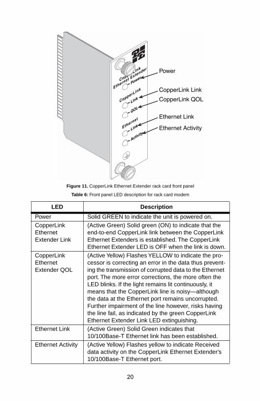
Figure 11. CopperLink Ethernet Extender rack card front panel
Table 6: Front panel LED description for rack card modem
LED Description
Power Solid GREEN to indicate the unit is powered on.CopperLink Ethernet Extender Link
(Active Green) Solid green (ON) to indicate that the end-to-end CopperLink link between the CopperLink Ethernet Extenders is established. The CopperLink Ethernet Extender LED is OFF when the link is down.
CopperLink Ethernet Extender QOL
(Active Yellow) Flashes YELLOW to indicate the pro-cessor is correcting an error in the data thus prevent-ing the transmission of corrupted data to the Ethernet port. The more error corrections, the more often the LED blinks. If the light remains lit continuously, it means that the CopperLink line is noisy—although the data at the Ethernet port remains uncorrupted. Further impairment of the line however, risks having the line fail, as indicated by the green CopperLink Ethernet Extender Link LED extinguishing.
Ethernet Link (Active Green) Solid Green indicates that 10/100Base-T Ethernet link has been established.
Ethernet Activity (Active Yellow) Flashes yellow to indicate Received data activity on the CopperLink Ethernet Extender’s 10/100Base-T Ethernet port.
20
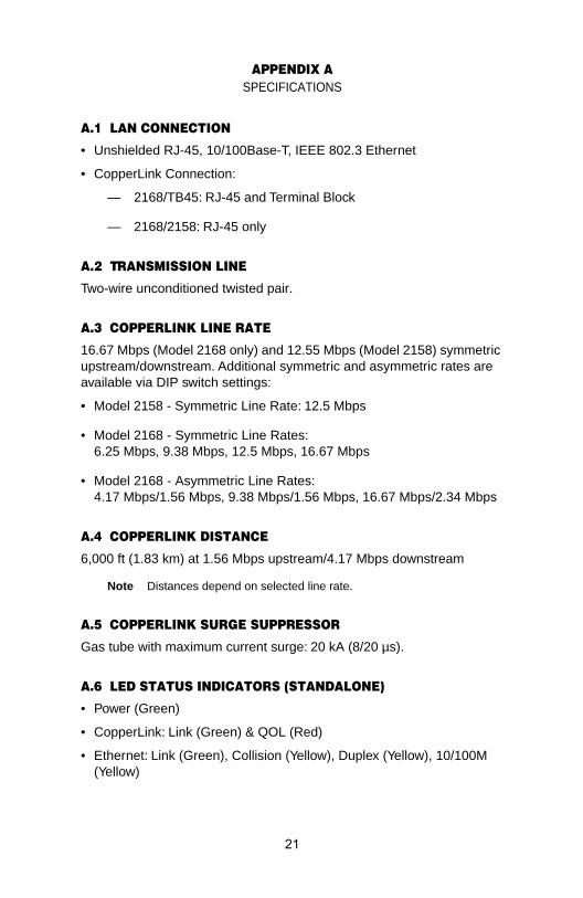
APPENDIX ASPECIFICATIONS
A.1 LAN CONNECTION
• Unshielded RJ-45, 10/100Base-T, IEEE 802.3 Ethernet
• CopperLink Connection:
— 2168/TB45: RJ-45 and Terminal Block
— 2168/2158: RJ-45 only
A.2 TRANSMISSION LINE
Two-wire unconditioned twisted pair.
A.3 COPPERLINK LINE RATE
16.67 Mbps (Model 2168 only) and 12.55 Mbps (Model 2158) symmetric upstream/downstream. Additional symmetric and asymmetric rates are available via DIP switch settings:
• Model 2158 - Symmetric Line Rate: 12.5 Mbps
• Model 2168 - Symmetric Line Rates: 6.25 Mbps, 9.38 Mbps, 12.5 Mbps, 16.67 Mbps
• Model 2168 - Asymmetric Line Rates: 4.17 Mbps/1.56 Mbps, 9.38 Mbps/1.56 Mbps, 16.67 Mbps/2.34 Mbps
A.4 COPPERLINK DISTANCE
6,000 ft (1.83 km) at 1.56 Mbps upstream/4.17 Mbps downstream
Note Distances depend on selected line rate.
A.5 COPPERLINK SURGE SUPPRESSOR
Gas tube with maximum current surge: 20 kA (8/20 µs).
A.6 LED STATUS INDICATORS (STANDALONE)
• Power (Green)
• CopperLink: Link (Green) & QOL (Red)
• Ethernet: Link (Green), Collision (Yellow), Duplex (Yellow), 10/100M (Yellow)
21
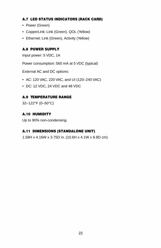
A.7 LED STATUS INDICATORS (RACK CARD)
• Power (Green)
• CopperLink: Link (Green), QOL (Yellow)
• Ethernet: Link (Green), Activity (Yellow)
A.8 POWER SUPPLY
Input power: 5 VDC, 1A
Power consumption: 560 mA at 5 VDC (typical)
External AC and DC options:
• AC: 120 VAC, 220 VAC, and UI (120–240 VAC)
• DC: 12 VDC, 24 VDC and 48 VDC
A.9 TEMPERATURE RANGE
32–122°F (0–50°C)
A.10 HUMIDITY
Up to 90% non-condensing.
A.11 DIMENSIONS (STANDALONE UNIT)
1.58H x 4.16W x 3.75D in. (10.6H x 4.1W x 8.8D cm)
22
P
Ba21
21
21
21
21 -
21
21 ,
21
212P
)
21 -
21 -
21 k
21
212P
)
07
Po0808
12
24
48
Po08
08
08
08
08
08
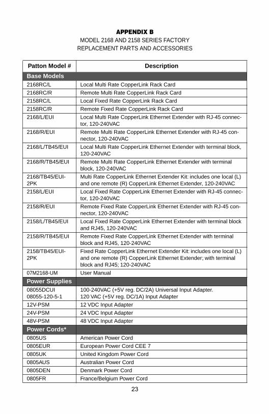
APPENDIX BMODEL 2168 AND 2158 SERIES FACTORY
REPLACEMENT PARTS AND ACCESSORIES
atton Model # Description
se Models68RC/L Local Multi Rate CopperLink Rack Card
68RC/R Remote Multi Rate CopperLink Rack Card
58RC/L Local Fixed Rate CopperLink Rack Card
58RC/R Remote Fixed Rate CopperLink Rack Card
68/L/EUI Local Multi Rate CopperLink Ethernet Extender with RJ-45 connector, 120-240VAC
68/R/EUI Remote Multi Rate CopperLink Ethernet Extender with RJ-45 con-nector, 120-240VAC
68/L/TB45/EUI Local Multi Rate CopperLink Ethernet Extender with terminal block120-240VAC
68/R/TB45/EUI Remote Multi Rate CopperLink Ethernet Extender with terminal block, 120-240VAC
68/TB45/EUI-K
Multi Rate CopperLink Ethernet Extender Kit: includes one local (Land one remote (R) CopperLink Ethernet Extender, 120-240VAC
58/L/EUI Local Fixed Rate CopperLink Ethernet Extender with RJ-45 connector, 120-240VAC
58/R/EUI Remote Fixed Rate CopperLink Ethernet Extender with RJ-45 connector, 120-240VAC
58/L/TB45/EUI Local Fixed Rate CopperLink Ethernet Extender with terminal blocand RJ45, 120-240VAC
58/R/TB45/EUI Remote Fixed Rate CopperLink Ethernet Extender with terminal block and RJ45, 120-240VAC
58/TB45/EUI-K
Fixed Rate CopperLink Ethernet Extender Kit: includes one local (Land one remote (R) CopperLink Ethernet Extender; with terminal block and RJ45; 120-240VAC
M2168-UM User Manual
wer Supplies055DCUI055-120-5-1
100-240VAC (+5V reg. DC/2A) Universal Input Adapter.120 VAC (+5V reg. DC/1A) Input Adapter
V-PSM 12 VDC Input Adapter
V-PSM 24 VDC Input Adapter
V-PSM 48 VDC Input Adapter
wer Cords*05US American Power Cord
05EUR European Power Cord CEE 7
05UK United Kingdom Power Cord
05AUS Australian Power Cord
05DEN Denmark Power Cord
05FR France/Belgium Power Cord
23

08
08
08
08
P
*Only required with optional UI power supply (08055DCUI)
05IN India Power Cord
05IS Israel Power Cord
05JAP Japan Power Cord
05SW Switzerland Power Cord
atton Model # Description
24
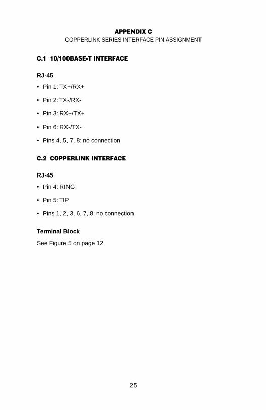
APPENDIX CCOPPERLINK SERIES INTERFACE PIN ASSIGNMENT
C.1 10/100BASE-T INTERFACE
RJ-45
• Pin 1: TX+/RX+
• Pin 2: TX-/RX-
• Pin 3: RX+/TX+
• Pin 6: RX-/TX-
• Pins 4, 5, 7, 8: no connection
C.2 COPPERLINK INTERFACE
RJ-45
• Pin 4: RING
• Pin 5: TIP
• Pins 1, 2, 3, 6, 7, 8: no connection
Terminal Block
See Figure 5 on page 12.
25
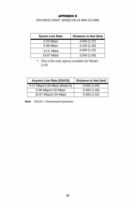
APPENDIX DDISTANCE CHART, BASED ON 24 AWG (0.5 MM)
Note DS/US = Downstream/Upstream.
Symm Line Rate Distance in feet (km)
6.25 Mbps 4,500 (1.37)9.38 Mbps 4,150 (1.26)
*12.5 Mbps
*. This is the only option available for Model 2158.
4,000 (1.22)
16.67 Mbps 3,300 (1.00)
Asymm Line Rate (DS/US) Distance in feet (km)
4.17 Mbps/1.56 Mbps (Mode 0) 6,000 (1.83)9.38 Mbps/1.56 Mbps 5,500 (1.68)
16.67 Mbps/2.34 Mbps 5,000 (1.52)
26

Notes
_________________________________________________________
_________________________________________________________
_________________________________________________________
_________________________________________________________
_________________________________________________________
_________________________________________________________
_________________________________________________________
_________________________________________________________
_________________________________________________________
_________________________________________________________
_________________________________________________________
_________________________________________________________
_________________________________________________________
_________________________________________________________
_________________________________________________________
_________________________________________________________
_________________________________________________________
_________________________________________________________
_________________________________________________________
_________________________________________________________
_________________________________________________________
_________________________________________________________
_________________________________________________________
_________________________________________________________
_________________________________________________________
27

Notes
_________________________________________________________
_________________________________________________________
_________________________________________________________
_________________________________________________________
_________________________________________________________
_________________________________________________________
_________________________________________________________
_________________________________________________________
_________________________________________________________
_________________________________________________________
_________________________________________________________
_________________________________________________________
_________________________________________________________
_________________________________________________________
_________________________________________________________
_________________________________________________________
_________________________________________________________
_________________________________________________________
_________________________________________________________
_________________________________________________________
_________________________________________________________
Copyright © 2006Patton Electronics Company
All Rights Reserved.
28