Embed Size (px)
DESCRIPTION
COP 3813 Introduction to Internet Computing Xingquan (Hill) Zhu [email protected]. Course topics. Introduction XHTML CSS (Cascading Style Sheets) Client Side JavaScript Dynamic HTML Server Side PHP Database ASP.NET XML. Content. Introduction to Internet and Computer Networks - PowerPoint PPT Presentation
Citation preview

Introduction 1-2
Course topics Introduction XHTML CSS (Cascading Style Sheets) Client Side
JavaScript Dynamic HTML
Server Side PHP Database ASP.NET
XML

Introduction 1-3
Content
Introduction to Internet and Computer Networks What are computer networks What is the Internet The history of Internet
Introduction 1-4
Computer Networks What are computer networks?
Interconnected collection of autonomous computer
A system for “communication” between “computers” Examples of computer networks
the point-of-sale terminals in a computerised store an office with three computers connected to share data a large company with many interconnected computers sharing resources
and security systems.
Advantages Computing, Communication and information sharing
Disadvantages potential loss of security loss of speed cost of purchase and set-up maintenance and supervision costs

Introduction 1-5
Computer Networks = Internet ?
Type of networks Local Area Networks (LAN)
• Restricted in size; building, campus Metropolitan (MAN) Area Networks
• Size in ten km and may cover a city Wide Area Networks (WAN)
• Within a country or even whole continent, size from 10km to over several hundred km
Internet• Deal with how to connect different kinds of
networks, resulting the Internet which really covers the whole Planet.

Introduction 1-6
Two most important aspects of CN Hardware
As communication is a primary concern in a network, we are dealing with both computers and communication technologies
• Computing, communication and interaction devices
Software Protocols
• How to exchange information Services
• What networks offer Interfaces
• How the services can be accessed

Introduction 1-7
What’s the Internet: “nuts and bolts” view
millions of connected computing devices: hosts = end systems
running network apps communication links
fiber, copper, radio, satellite
transmission rate = bandwidth
routers: forward packets (chunks of data)
local ISP
companynetwork
regional ISP
router workstation
servermobile

Introduction 1-8
“Cool” internet appliances
World’s smallest web serverhttp://www-ccs.cs.umass.edu/~shri/iPic.html
IP picture framehttp://www.ceiva.com/
Web-enabled toaster +weather forecaster
Internet phones

Introduction 1-9
What’s the Internet: “nuts and bolts” view protocols control sending,
receiving of msgs e.g., TCP, IP, HTTP, FTP,
PPP
Internet: “network of networks” loosely hierarchical public Internet versus
private intranet
Internet standards RFC: Request for comments IETF: Internet Engineering
Task Force
local ISP
companynetwork
regional ISP
router workstation
servermobile

Introduction 1-10
What’s the Internet: a service view communication
infrastructure enables distributed applications: Web, email, games, e-
commerce, file sharing communication services
provided to apps: Connectionless unreliable connection-oriented reliable
Internet provides services with no guarantee No guaranteed transmission
delay No guaranteed bandwidth

Introduction 1-11
What’s a protocol?human protocols: Understand each
others & follow each others “what’s the time?” “I have a question” introductions
… specific msgs sent… specific actions
taken when msgs received, or other events
network protocols: machines rather
than humans all communication
activity in Internet governed by protocols
protocols define format, order of msgs sent and
received among network entities, and actions taken on msg transmission, receipt

Introduction 1-12
What’s a protocol?a human protocol and a computer network protocol:
Q: Other human protocols?
Hi
Hi
Got thetime?
2:00
TCP connection request
TCP connectionresponseGet http://www.awl.com/kurose-ross
<file>time

Introduction 1-13
A closer look at network structure: network edge:
applications and hosts network core:
routers network of networks
access networks, physical media: communication links

Introduction 1-14
What is the Internet?
Network edge Network coreDelay & loss in packet-switched
networksInternet structure and ISPs Protocol layers, service modelsHistory

Introduction 1-15
The network edge: end systems (hosts):
run application programs e.g. Web, email at “edge of network”
client/server model client host requests, receives
service from always-on server e.g. Web browser/server;
email client/server
peer-peer model: minimal (or no) use of
dedicated servers e.g. Gnutella, KaZaA, Skype

Introduction 1-16
Network edge: connection-oriented service
Goal: data transfer between end systems
handshaking: setup (prepare for) data transfer ahead of time Hello, hello back
human protocol set up “state” in two
communicating hosts
TCP - Transmission Control Protocol Internet’s connection-
oriented service
TCP service [RFC 793] reliable, in-order byte-
stream data transfer loss: acknowledgements
and retransmissions
flow control: sender won’t overwhelm
receiver
congestion control: senders “slow down
sending rate” when network congested

Introduction 1-17
Network edge: connectionless service
Goal: data transfer between end systems same as before!
UDP - User Datagram Protocol [RFC 768]: connectionless unreliable data
transfer no flow control no congestion
control
App’s using TCP: HTTP (Web), FTP (file
transfer), Telnet (remote login), SMTP (email)
App’s using UDP: streaming media,
teleconferencing, DNS, Internet telephony

Introduction 1-18
What is the Internet?
Network edge End systems, client/server, connection-
oriented/connectionless services Network coreDelay & loss in packet-switched
networksInternet structure and ISPs Protocol layers, service modelsHistory
Introduction 1-19
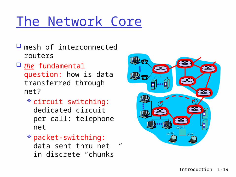
The Network Core
mesh of interconnected routers
the fundamental question: how is data transferred through net? circuit switching:
dedicated circuit per call: telephone net
packet-switching: data sent thru net in discrete “chunks”

Introduction 1-20
Network Core: Circuit Switching.
End-end resources reserved for “call”
link bandwidth, switch capacity
dedicated resources: no sharing
circuit-like (guaranteed) performance
call setup required

Introduction 1-21
Circuit Switching: FDM and TDM
FDM: Frequency division multiplexing
frequency
time
TDM: Time division multiplexing
frequency
time
4 users
Example:

Introduction 1-22
Packet Switching: Statistical Multiplexing
Sequence of A & B packets does not have fixed pattern, shared on demand statistical multiplexing.
A
B
C10 Mb/sEthernet
1.5 Mb/s
D E
statistical multiplexing
queue of packetswaiting for output
link

Introduction 1-23
Packet switching versus circuit switching.
1 Mb/s link each user:
100 kb/s when “active”
active 10% of time
circuit-switching: 10 users
packet switching: with 35 users,
probability > 10 active less than .0004
Packet switching allows more users to use network!
N users
1 Mbps link

Introduction 1-24
Packet-switching: store-and-forward.
Takes L/R seconds to transmit (push out) packet of L bits on to link or R bps
Entire packet must arrive at router before it can be transmitted on next link: store and forward
delay = 3L/R (assuming zero propagation delay)
R R RL

Introduction 1-25
What is the Internet?
Network edge End systems, client/server, connection-
oriented/connectionless services Network coreDelay & loss in packet-switched
networksInternet structure and ISPs Protocol layers, service modelsHistory

Introduction 1-26
How do loss and delay occur?packets queue in router buffers packet arrival rate to link exceeds output link
capacity packets queue, wait for turn
A
B
packet being transmitted (delay)
packets queueing (delay)
free (available) buffers: arriving packets dropped (loss) if no free buffers
Introduction 1-27
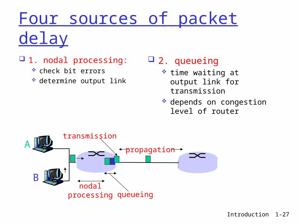
Four sources of packet delay
1. nodal processing: check bit errors determine output link
A
B
propagation
transmission
nodalprocessing queueing
2. queueing time waiting at output
link for transmission depends on congestion
level of router

Introduction 1-28
Delay in packet-switched networks3. Transmission delay: R=link bandwidth
(bps) L=packet length (bits) time to send bits into
link = L/R
4. Propagation delay: d = length of physical
link s = propagation speed in
medium (~2x10⁸ m/sec) propagation delay = d/s
A
B
propagation
transmission
nodalprocessing queueing
Note: s and R are very different quantities!

Introduction 1-29
“Real” Internet delays and routes What do “real” Internet delay & loss look like? Traceroute program: provides delay
measurement from source to router along end-end Internet path towards destination. For all i: sends three packets that will reach router i on path
towards destination router i will return packets to sender sender times interval between transmission and reply.
3 probes
3 probes
3 probes
Introduction 1-30
“Real” Internet delays and routes
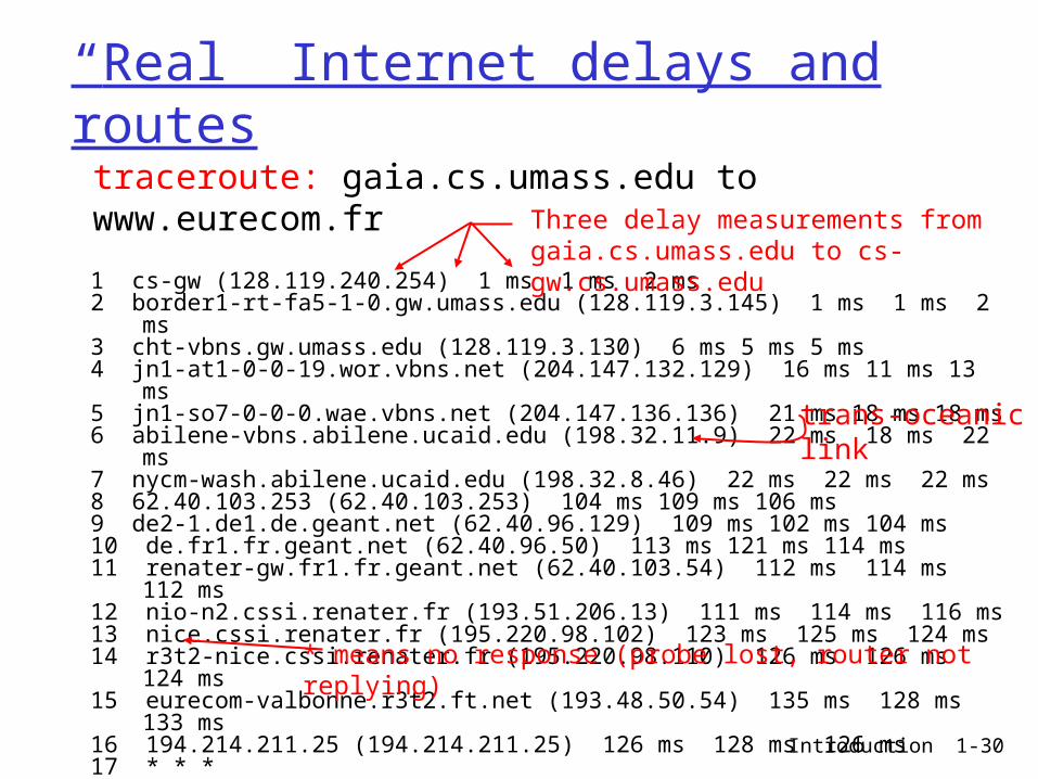
1 cs-gw (128.119.240.254) 1 ms 1 ms 2 ms2 border1-rt-fa5-1-0.gw.umass.edu (128.119.3.145) 1 ms 1 ms 2 ms3 cht-vbns.gw.umass.edu (128.119.3.130) 6 ms 5 ms 5 ms4 jn1-at1-0-0-19.wor.vbns.net (204.147.132.129) 16 ms 11 ms 13 ms 5 jn1-so7-0-0-0.wae.vbns.net (204.147.136.136) 21 ms 18 ms 18 ms 6 abilene-vbns.abilene.ucaid.edu (198.32.11.9) 22 ms 18 ms 22 ms7 nycm-wash.abilene.ucaid.edu (198.32.8.46) 22 ms 22 ms 22 ms8 62.40.103.253 (62.40.103.253) 104 ms 109 ms 106 ms9 de2-1.de1.de.geant.net (62.40.96.129) 109 ms 102 ms 104 ms10 de.fr1.fr.geant.net (62.40.96.50) 113 ms 121 ms 114 ms11 renater-gw.fr1.fr.geant.net (62.40.103.54) 112 ms 114 ms 112 ms12 nio-n2.cssi.renater.fr (193.51.206.13) 111 ms 114 ms 116 ms13 nice.cssi.renater.fr (195.220.98.102) 123 ms 125 ms 124 ms14 r3t2-nice.cssi.renater.fr (195.220.98.110) 126 ms 126 ms 124 ms15 eurecom-valbonne.r3t2.ft.net (193.48.50.54) 135 ms 128 ms 133 ms16 194.214.211.25 (194.214.211.25) 126 ms 128 ms 126 ms17 * * *18 * * *19 fantasia.eurecom.fr (193.55.113.142) 132 ms 128 ms 136 ms
traceroute: gaia.cs.umass.edu to www.eurecom.frThree delay measurements from gaia.cs.umass.edu to cs-gw.cs.umass.edu
* means no response (probe lost, router not replying)
trans-oceaniclink

Introduction 1-31
Packet loss
queue (aka buffer) preceding link in buffer has finite capacity
when packet arrives to full queue, packet is dropped (aka lost)
lost packet may be retransmitted by previous node, by source end system, or not retransmitted at all

Introduction 1-32
What is the Internet?
Network edge End systems, client/server, connection-
oriented/connectionless services Network coreDelay & loss in packet-switched
networksInternet structure and ISPs Protocol layers, service modelsHistory

Introduction 1-33
Internet structure: network of networks
roughly hierarchical at center: “tier-1” ISPs (e.g., MCI, Sprint, AT&T,
Cable and Wireless), national/international coverage treat each other as equals
Tier 1 ISP
Tier 1 ISP
Tier 1 ISP
Tier-1 providers interconnect (peer) privately
NAP
Tier-1 providers also interconnect at public network access points (NAPs)

Introduction 1-34
Tier-1 ISP: e.g., Sprint
Sprint US backbone network
Seattle
Atlanta
Chicago
Roachdale
Stockton
San Jose
Anaheim
Fort Worth
Orlando
Kansas City
CheyenneNew York
PennsaukenRelay
Wash. DC
Tacoma
DS3 (45 Mbps)OC3 (155 Mbps)OC12 (622 Mbps)OC48 (2.4 Gbps)
…
to/from customers
peering
to/from backbone
….
………POP: point-of-presence
Introduction 1-35
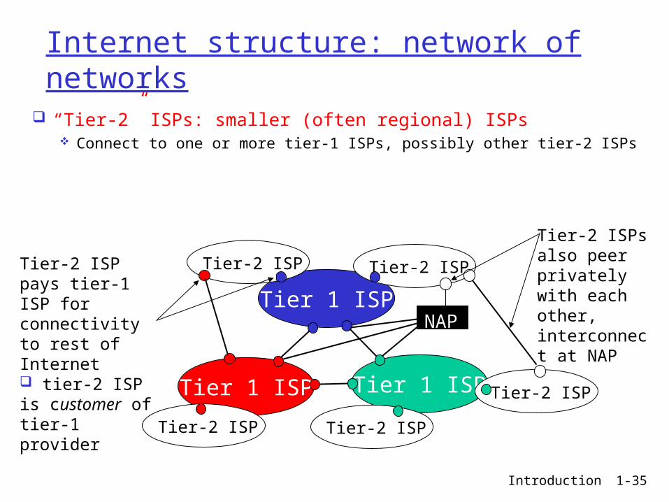
Internet structure: network of networks
“Tier-2” ISPs: smaller (often regional) ISPs Connect to one or more tier-1 ISPs, possibly other tier-2 ISPs
Tier 1 ISP
Tier 1 ISP
Tier 1 ISP
NAP
Tier-2 ISPTier-2 ISP
Tier-2 ISP Tier-2 ISP
Tier-2 ISP
Tier-2 ISP pays tier-1 ISP for connectivity to rest of Internet tier-2 ISP is customer oftier-1 provider
Tier-2 ISPs also peer privately with each other, interconnect at NAP

Introduction 1-36
Internet structure: network of networks
“Tier-3” ISPs and local ISPs last hop (“access”) network (closest to end systems)
Tier 1 ISP
Tier 1 ISP
Tier 1 ISP
NAP
Tier-2 ISPTier-2 ISP
Tier-2 ISP Tier-2 ISP
Tier-2 ISP
localISPlocal
ISPlocalISP
localISP
localISP Tier 3
ISP
localISP
localISP
localISP
Local and tier- 3 ISPs are customers ofhigher tier ISPsconnecting them to rest of Internet

Introduction 1-37
Internet structure: network of networks
a packet passes through many networks!
Tier 1 ISP
Tier 1 ISP
Tier 1 ISP
NAP
Tier-2 ISPTier-2 ISP
Tier-2 ISP Tier-2 ISP
Tier-2 ISP
localISPlocal
ISPlocalISP
localISP
localISP Tier 3
ISP
localISP
localISP
localISP

Introduction 1-38
What is the Internet?
Network edge End systems, client/server, connection-
oriented/connectionless services Network coreDelay & loss in packet-switched
networksInternet structure and ISPs Protocol layers, service modelsHistory

Introduction 1-39
Protocol “Layers”Networks are
complex! many “pieces”:
hosts routers links of various
media applications protocols hardware,
software
Question: Is there any hope of organizing structure of
network?
Or at least our discussion of networks?
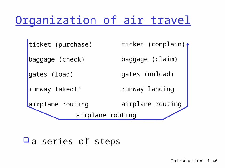
Introduction 1-40
Organization of air travel
a series of steps
ticket (purchase)
baggage (check)
gates (load)
runway takeoff
airplane routing
ticket (complain)
baggage (claim)
gates (unload)
runway landing
airplane routing
airplane routing

Introduction 1-41
ticket (purchase)
baggage (check)
gates (load)
runway (takeoff)
airplane routing
departureairport
arrivalairport
intermediate air-trafficcontrol centers
airplane routing airplane routing
ticket (complain)
baggage (claim
gates (unload)
runway (land)
airplane routing
ticket
baggage
gate
takeoff/landing
airplane routing
Layering of airline functionality
Layers: each layer implements a service via its own internal-layer actions relying on services provided by layer below

Introduction 1-42
Why layering?
Dealing with complex systems: explicit structure allows identification,
relationship of complex system’s pieces layered reference model for discussion
modularization eases maintenance, updating of system change of implementation of layer’s service
transparent to rest of system e.g., change in gate procedure doesn’t
affect rest of system

Introduction 1-43
Internet protocol stack application: supporting network
applications FTP, SMTP, HTTP
transport: host-host data transfer TCP, UDP
network: routing of datagrams from source to destination IP, routing protocols
link: data transfer between neighboring network elements PPP, Ethernet
physical: bits “on the wire”
application
transport
network
link
physical
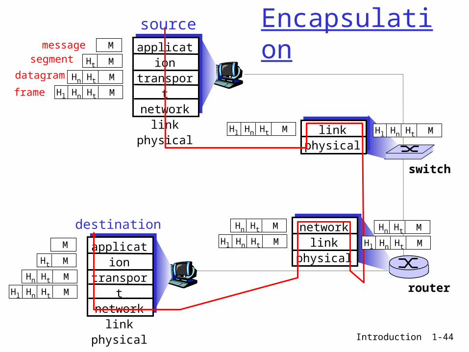
Introduction 1-44
messagesegment
datagram
frame
sourceapplicatio
ntransportnetwork
linkphysical
HtHnHl M
HtHn M
Ht M
M
destination
application
transportnetwork
linkphysical
HtHnHl M
HtHn M
Ht M
M
networklink
physical
linkphysical
HtHnHl M
HtHn M
HtHnHl M
HtHn M
HtHnHl M HtHnHl M
router
switch
Encapsulation

Introduction 1-45
What is the Internet?.
Network edge End systems, client/server, connection-
oriented/connectionless services Network coreDelay & loss in packet-switched
networksInternet structure and ISPs Protocol layers, service modelsHistory

Introduction 1-46
Internet History
1961: Kleinrock (MIT) - queueing theory shows effectiveness of packet-switching
1964: Baran (Rand Inst.) - packet-switching in military nets
1964 Davies (NPL) – Packet switching
1967: ARPAnet conceived by Advanced Research Projects Agency
1969: first ARPAnet node operational
1972: ARPAnet public demonstration NCP (Network Control Protocol)
first host-host protocol first e-mail program ARPAnet has 15 nodes
1961-1972: Early packet-switching principles

Introduction 1-47
Internet History
1970: ALOHAnet satellite network in Hawaii
1974: Cerf and Kahn - architecture for interconnecting networks
1976: Ethernet at Xerox PARC
ate70’s: proprietary architectures: DECnet, SNA, XNA
late 70’s: switching fixed length packets (ATM precursor)
1979: ARPAnet has 200 nodes
Cerf and Kahn’s internetworking principles: minimalism, autonomy -
no internal changes required to interconnect networks
best effort service model stateless routers decentralized control
define today’s Internet architecture
1972-1980: Internetworking, new and proprietary nets

Introduction 1-48
Internet History
1983: deployment of TCP/IP
1982: smtp e-mail protocol defined
1983: DNS defined for name-to-IP-address translation
1985: ftp protocol defined
1988: TCP congestion control
new national networks: Csnet, BITnet, NSFnet, Minitel
100,000 hosts connected to confederation of networks
1980-1990: new protocols, a proliferation of networks

Introduction 1-49
Internet History
Early 1990’s: ARPAnet decommissioned
1991: NSF lifts restrictions on commercial use of NSFnet (decommissioned, 1995)
early 1990s: Web hypertext [Bush 1945,
Nelson 1960’s] HTML, HTTP: Berners-Lee 1994: Mosaic, later
Netscape late 1990’s:
commercialization of the Web
Late 1990’s – 2000’s: more killer apps: instant
messaging, P2P file sharing
network security to forefront
est. 50 million host, 100 million+ users
backbone links running at Gbps
1990, 2000’s: commercialization, the Web, new apps

Introduction 1-50
Summary
Covered a “ton” of material! Internet overview network edge, core, access network
packet-switching versus circuit-switching loss & delay what’s a protocol? layering and service models history