Embed Size (px)
Citation preview

Cooperative Techniques in LTE-Advanced Networks
Md Shamsul Alam
Introduction
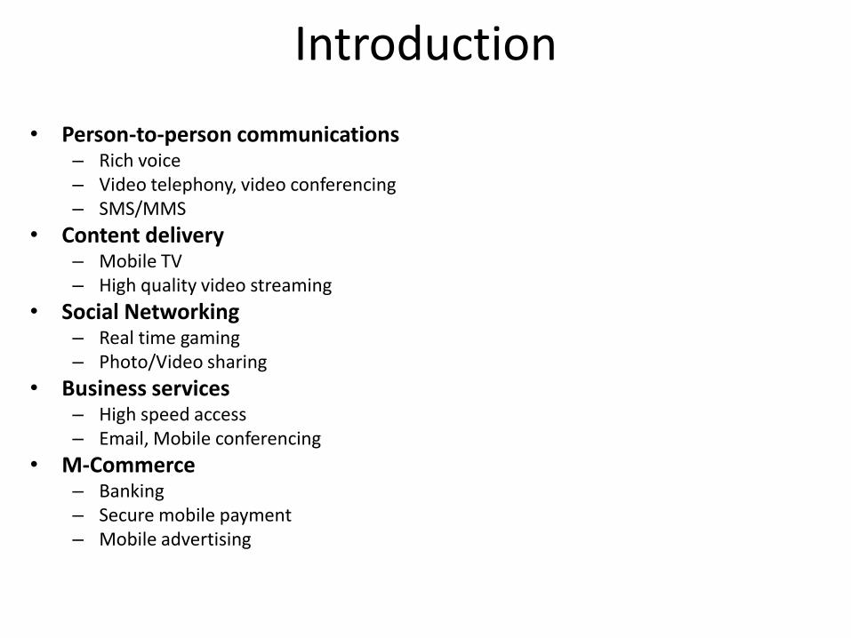
• Person-to-person communications – Rich voice – Video telephony, video conferencing – SMS/MMS
• Content delivery – Mobile TV – High quality video streaming
• Social Networking – Real time gaming – Photo/Video sharing
• Business services – High speed access – Email, Mobile conferencing
• M-Commerce – Banking – Secure mobile payment – Mobile advertising

Introduction
• Faster, Simpler, More Efficient, Cheaper • Highly efficient radio technology
– Increased spectrum efficiency and therefore increase capacity – Lower cost per bit and lower prices for the end user
• Simplified protocol stack and all IP network – Reduced latency – Easier network management – CAPEX and OPEX savings
• Flexibility and scalability in deployment – Operating in various frequencies and bandwidths – Operators can start with smaller deployment and increase
bandwidth as demand increase – Supports resource aggregation
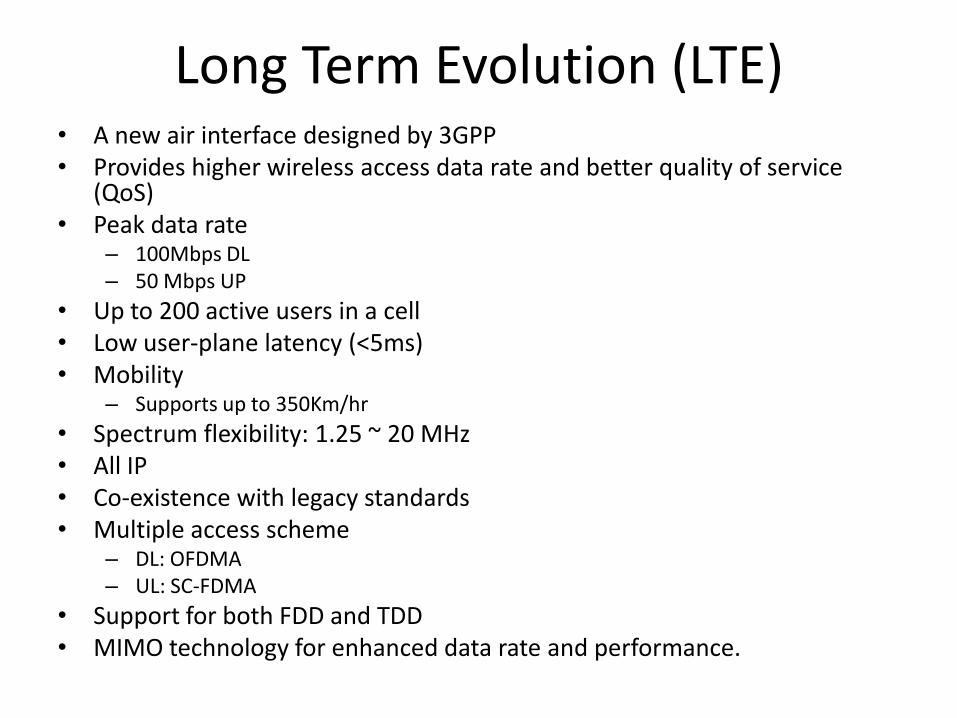
Long Term Evolution (LTE) • A new air interface designed by 3GPP • Provides higher wireless access data rate and better quality of service
(QoS) • Peak data rate
– 100Mbps DL – 50 Mbps UP
• Up to 200 active users in a cell • Low user-plane latency (<5ms) • Mobility
– Supports up to 350Km/hr
• Spectrum flexibility: 1.25 ~ 20 MHz • All IP • Co-existence with legacy standards • Multiple access scheme
– DL: OFDMA – UL: SC-FDMA
• Support for both FDD and TDD • MIMO technology for enhanced data rate and performance.
LTE-Advanced
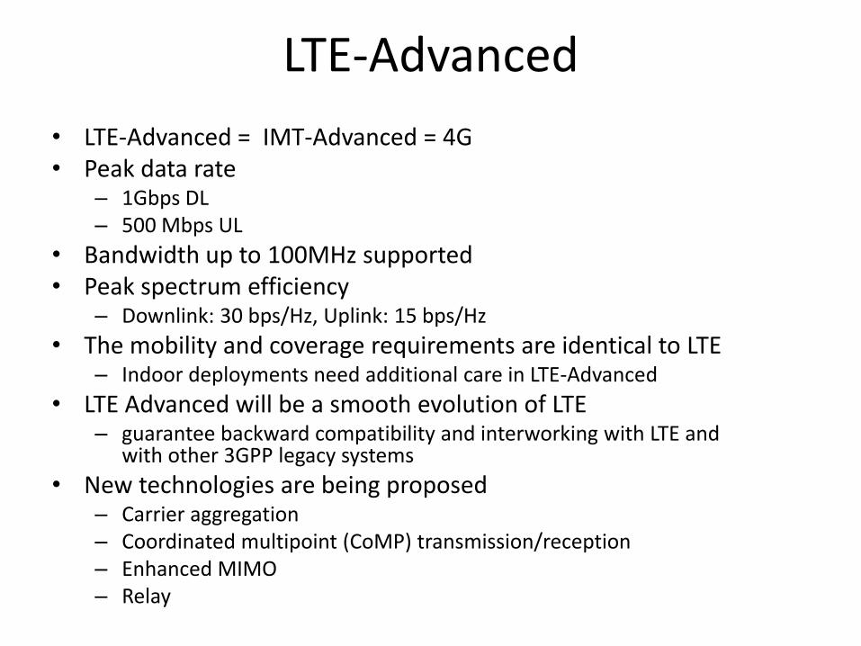
• LTE-Advanced = IMT-Advanced = 4G • Peak data rate
– 1Gbps DL – 500 Mbps UL
• Bandwidth up to 100MHz supported • Peak spectrum efficiency
– Downlink: 30 bps/Hz, Uplink: 15 bps/Hz
• The mobility and coverage requirements are identical to LTE – Indoor deployments need additional care in LTE-Advanced
• LTE Advanced will be a smooth evolution of LTE – guarantee backward compatibility and interworking with LTE and
with other 3GPP legacy systems
• New technologies are being proposed – Carrier aggregation – Coordinated multipoint (CoMP) transmission/reception – Enhanced MIMO – Relay

Coordinated Multipoint (CoMP)Transmission and Reception
• Traditionally, in cellular systems, each user is assigned to a base station on the basis of criteria such as signal strength.
• At the terminal side, all the signals coming from the rest of base stations in the form of interference dramatically limit the performance.
• The user also communicates with a single serving base station while causing interference to the rest of them.
• One strategy is to reduce the inter-cell interference with the help of cooperative transmission
• CoMP transmission and reception is a framework that refers to a system where several geographically distributed antenna nodes cooperate with the aim of improving the performance of the users served in the common cooperation area.

CoMP
• Very-high-speed dedicated links – Optical fiber, wired backbone connection or even highly
directional wireless microwave links
• CoMP downlink – performing a coordinated transmission from the base
station
• CoMP Uplink – Whereas interference in the uplink can be reduced by
means of a coordinated reception in eNBs
• Intra-site CoMP – Remote Radio Equipment
• Inter-site CoMP

CoMP

Centralized CoMP Approach
eNB1
eNB3
eNB2
Central Unit
CSI
CSI
CSI
UE1
UE2
UE3

Distributed CoMP Approach
CSI
CSI
CSI
CSI
CSI CSI
CSI
CSI
CSI
eNB1
eNB2
eNB3
UE1
UE2
UE3

DL CoMP Techniques
• Coordinated Beamforming – The transmission to a single UE is transmitted from
the serving cell, exactly as in the case of non-CoMP transmission
– However, the scheduling, including any beamforming functionality is dynamically coordinated between the cells
– The best serving set of users will be selected so that the transmitter beams are constructed to reduce the interference to other neighboring users, while increasing the served user’s signal strength.

CB
• Joint Processing • The transmission to a single UE is simultaneously transmitted
from multiple transmission points across cell sites
• This scheme has the potential for higher performance, but comes at the expense of more stringent requirement on backhaul communication.
• Joint Transmission – Serving set determination
– Coherent and non-coherent transmission
• Dynamic Cell Selection

Signal Combining Fast Selection
Joint Transmission Dynamic Cell Selection

Issues
– Synchronization
– Channel estimation and feed back
– Backhaul aspects
– Reference signal design
– Base station selection
– Resource allocation
CoMP with Relaying
• Relaying can be combined with CoMP
• Three types of cooperation can occur
– Cooperation between RNs
– Cooperation between RNs and eNBs
– Cooperation between eNBs
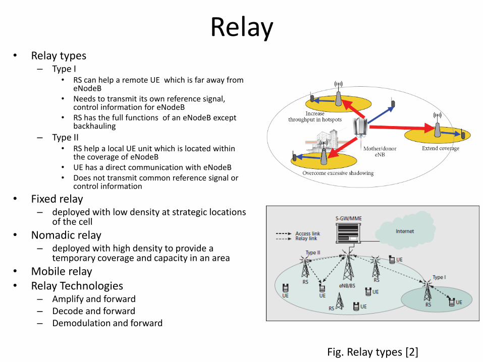
Relay • Relay types
– Type I • RS can help a remote UE which is far away from
eNodeB • Needs to transmit its own reference signal,
control information for eNodeB • RS has the full functions of an eNodeB except
backhauling
– Type II • RS help a local UE unit which is located within
the coverage of eNodeB • UE has a direct communication with eNodeB • Does not transmit common reference signal or
control information
• Fixed relay – deployed with low density at strategic locations
of the cell
• Nomadic relay – deployed with high density to provide a
temporary coverage and capacity in an area
• Mobile relay • Relay Technologies
– Amplify and forward – Decode and forward – Demodulation and forward
Fig. Relay types [2]