Embed Size (px)
Citation preview

Cooling your industry,optimising your process.
Refrigeratori di liquido con free-cooling integrato con compressori semiermetici a vite. Potenze frigorifere 187 - 494 kW. Air-cooled liquid chillers with integrated free-cooling system featuring semihermetic screw compressors. Cooling capacity 187 - 494 kW.

IND
ICE
- IN
DEX
3
Specifiche tecnicheTechnical specifications ....................................................................................................... 4
Guida alla selezioneSelection guide ................................................................................................................... 12
Prestazioni e dati tecniciPerformance and technical data ......................................................................................16
Perdite di caricoPressure drops ....................................................................................................................36
Limiti di funzionamento e coefficienti correttiviWorking limits and correction factors ............................................................................... 37
Disegni di ingombroOverall dimensions ........................................................................................................... 38
Guida all’installazioneInstallation guide ............................................................................................................... 43
PHO
ENIX
Fre
e-Co
olin
g
4
SPECIFICHE TECNICHE - TECHNICAL SPECIFICATIONS
1 General2 Operation3 Nameplate4 Available configurations5 Description of mains components 5.1 Cooling circuit 5.2 Hydraulic circuit 5.3 Structure and casing 5.4 Electrical panels 5.5 Fans motor 5.6 Devices of safety and control 5.7 Control 5.8 Testing6 Accessories supplyed as kit separately
1. General
The new range of PHOENIX Free-Cooling units is a series of air cooled packaged water chillers with double screw type compressors, equipped with an new free-cooling integrated system with independent aeraulic circuits with very high energy efficiency.free-cooling is the best system for obtain high savings in electrical energy and it is particularly indicated in the industrial process cooling where the production of water cooled is required all year long.It consists in to exploit, in winter time and during the intermediate season, the low temperature of external air to cooling completly or only a part the water of process cooling is normally cooled through the compressors.During free-cooling functioning these chillers use an logical modulated type where the free-cooling of the water can happen every seasons of the year, with compressors OFF (total free-cooling , or with compressors partially ON (partial free-cooling).The PHOENIX Free-Cooling units have one or two independents cooling circuits and one compressor for circuit. The refrigerant gas utilized is R407C.The management of each PHOENIX Free-Cooling is entrusted to a microprocessor control which enable the management of all the components and the functioning parameters of units; In case of alarm an internal memory record the functioning conditions at the time that is happened.The PHOENIX Free-Cooling units have power supply 400/3/50, an protection rating IP54 and are therefore suitables for outdoor installations.Top quality brand components are carefully selected for these chillers that are designed, produced and tested in compliance with ISO9001.All the data presents in this catalogue refers to the standard units at the nominal conditions of working (except when differently specified).
(*) The ESEER indices (European Seasonal Energy Efficiency Ratio) proposed and used in the European design context, characterise the average weighted efficiency of a chiller. Both indices express, far more accurately than EER, the ratio between the useful effect (energy removed from interior spaces) and energy expenditure (electrical energy consumed) of a chiller during an entire season of operation. In relation to the various different operating conditions and the frequency with which they occur, these indicators are calculated by assigning a different energy weight to the corresponding output values of the unit.For example ESEER = 3,6 means that during an entire season of operation 1 kWh of electrical power is required on average to remove 3,6 kWh of heat energy from the air conditioned spaces.
1 Generalità2 Modalità di funzionamento3 Sigla4 Configurazioni disponibili5 Descrizione dei componenti principali 5.1 Circuito frigorifero 5.2 Circuito idraulico 5.3 Struttura e carenature 5.4 Quadro elettrico 5.5 Elettroventilatori 5.6 Dispositivi di sicurezza e controllo 5.7 Controllo 5.8 Collaudo6 Accessori fornibili come kit separati
1. Generalità
La nuova gamma di refrigeratori di liquido della serie PHOENIX Free-Cooling sono unità monoblocco condensate ad aria, con compressori semiermetici a doppia vite, dotate di un nuovo sistema di free-cooling integrato con sezioni aerauliche indipendenti ad altissima efficienza energetica. L’utilizzo del free-cooling è il sistema più efficace per conseguire notevoli risparmi di energia elettrica ed è particolarmente indicato nei processi industriali in cui la produzione di acqua refrigerata è richiesta tutto l’anno. Esso consiste nello sfruttare, in inverno e nelle stagioni intermedie, la bassa temperatura dell'aria esterna per raffreddare completamente o in parte l'acqua del circuito utenze normalmente raffreddata tramite il lavoro dei compressori frigoriferi.Nel funzionamento in free-cooling questi refrigeratori utilizzano una logica di tipo modulante in cui il raffreddamento gratuito dell'acqua può avvenire in ogni stagione dell’anno sia a compressori spenti (free-cooling totale) sia a compressori parzialmente accesi (free-cooling parziale).Le unità PHOENIX Free-Cooling sono costituite da uno o due circuiti frigoriferi indipendenti e da un compressore per circuito. Il fluido frigorigeno impiegato è l’R407C.La gestione di ogni refrigeratore PHOENIX Free-Cooling è affidata ad un controllo a microprocessore che gestisce tutti i componenti e i parametri di funzionamento delle unità; in caso di allarme una memoria interna registra le condizioni di funzionamento nel momento in cui esso ha avuto luogo.I PHOENIX Free-Cooling hanno alimentazione elettrica 400/3/50, un grado di protezione IP54 e sono quindi adatti ad essere installati all’esterno.Tutti i refrigeratori PHOENIX Free-Cooling sono realizzati utilizzando componenti di primaria marca, e sono progettati, prodotti e controllati in conformità alle norme ISO9001.Tutti i dati riportati in questo catalogo sono riferiti a macchine standard e a condizioni nominali di funzionamento (salvo quando specificato diversamente).
(*) Gli indici di prestazione stagionale ESEER (European Seasonal Energy Efficiency Ratio) proposto e utilizzato nel contesto progettuale europeo, caratterizzano l’efficienza media ponderata di un chiller. Questi indici esprimono, molto meglio del EER, il rapporto tra l’effetto utile (energia totale sottratta agli ambienti) e la spesa energetica (energia elettrica consumata) propri di una macchina frigorifera nel corso dell’intera stagione di funzionamento. In relazione alle differenti condizioni operative, e alla frequenza con cui esse si raggiungono, tali indicatori vengono calcolati assegnando un peso energetico differente alle corrispondenti prestazioni dell’unità.Ad esempio ESEER = 3,6 significa che, nel corso di un’intera stagione di funzionamento, per ogni 3,6 kWh termici sottratti agli ambienti da raffrescare verrà mediamente speso 1 kWh di energia elettrica.

PHO
ENIX
Fre
e-Co
olin
g
5
Percentuali di tempo di funzionamento secondo ESEERESEER operating time percentages
2. Modalità di funzionamento
L’acqua di proceso in ingresso alla macchina può fluire attraverso la batteria di free-cooling e poi passare nell’evaporatore, oppure essere dirottata direttamente nell’evaporatore, tramite una valvola a tre vie miscelatrice. Quando la temperatura aria esterna è inferiore alla temperatura dell’acqua di ritorno dagli utilizzi (almeno 2 °C), l’attuatore della valvola a tre vie commuta l’acqua aprendo la via “1” (come indicato nello schema qui sotto) ed è possibile pre-reffreddare tale acqua facendogli scambiare calore con l’ambiente tramite la batteria di free-cooling (free-cooling parziale). Allo scendere della temperatura aria ambiente, aumenta la percentuale del carico termico smaltito dalla batteria di free-cooling, fino ad ottenere un free-cooling totale (compressori fermi) e sostiture completamente il circuito frigorifero per temperature ambiente inferiori di circa 10 °C alla temperatura in uscita della miscela. Per temperature esterne ancora inferiori, il controllo elettronico riduce progressivamente la velocità di rotazione dei ventilatori di free-cooling, fino ad arrestarli. Nel caso la temperatura aria ambiente scenda ulteriormente, la valvola a tre vie by-passa una parte del flusso e lo miscela con il flusso uscente dalla batteria, mantenendo così in ogni situazione il perfetto controllo della temperatura della miscela in mandata. Nella gestione del free-cooling, la centralina di controllo a microprocessore dialoga con due sonde di temperatura, una nell’ambiente e una nel ritorno dell’acqua dagli utilizzi.
3. Sigla
Ogni refrigeratore è identificato dalla sigla:
PH XXX Y FC / ZZZ Config. acustica della macchina: C, SC, SF, SSF;
Abbreviazione di Free-Cooling;
Numero dei circuiti frigoriferi;
Potenza nominale dei compressori in HP;
Abbreviazione di PHOENIX.
4. Configurazioni disponibili
I refrigeratori di liquido della serie PHOENIX Free-Cooling sono disponibili in 10 modelli, con potenzialità nominali da 187 kW a 494 kW.Combinando opportunamente le configurazioni descritte in basso è
Pesi energetici secondo ESEERESEER energy weights
2. Operation
The process water entering the machine may flow through the free-cooling coils and then reach the evaporator, or it may be delivered directly to the evaporator through a three-way mixing valve. When the external air temperature is lower than the temperature of the water returning from the users (by at least 2 °C), the three-way valve’s actuator diverts the water by opening way “1” (as shown in the diagram below) so that this water can be pre-cooled by exchanging heat with the environment through the free-cooling coils (partial free-cooling). As the external temperature cools, the percentage of thermal load discharged by the free-cooling coils increases, until total free-cooling is reached (compressors off) and the refrigeration circuit is completely replaced; this occurs when the ambient temperature is approximately 10 °C lower than the outlet temperature of the mix. When the ambient temperature decreases, the electronic control gradually reduces the rotation speed of the free-cooling fans until they stop. If the aexternal air temperature drops even further, the three-way valve bypasses part of the flow and mixes it with the flow leaving the coils, thus maintaining perfect control of the temperature of the delivery mix in all conditions. For management of the free-cooling system, the microprocessor control unit receives information from two temperature probes, one located in the room and the other in the water return line.
3. Nameplate
Each chiller is identified by its nameplate:
PH XXX Y FC / ZZZ Acoustic configuration of the machine: C, SC, SF, SSF;
Free-Cooling abbreviation;
Number of cooling circuits;
Compressors nominal power, in HP;
PHOENIX abbreviation.
4. Available configurations
PHOENIX Free-Cooling air-cooled water chillers are availables in ten models, with nominal cooling capacity from 187 kW to 494 kW.With apposite combination of configurations, here below described, is
M
Ta
Ti FC
TuCHILLER
BTR FC
Ti
1
2
1.4%
25% 50% 75% 100%
ESEER
42%37%
20%
1,4%
25% 50% 75% 100%
23%
41%
33%
3,0%
ESEER
Carico termico Thermal load percentage Carico termico Thermal load percentage

PHO
ENIX
Fre
e-Co
olin
g
6
possibile rispondere alle più disparate esigenze impiantistiche.
Nel configurare le unità è importante ricordare che non tutte le combinazioni sono possibili, si raccomanda quindi di consultare la sezione PRESTAZIONI E DATI TECNICI di ogni modello o di contattare i nostri Uffici Commerciali.
• ALIMENTAZIONE ELETTRICA: 400V-3Ph-50Hz (standard)• CONFIGURAZIONI ACUSTICHE: - C: Adatta per ambienti fino a 45 °C; - SC: Adatta per ambienti fino a 41 °C, rispetto alla configurazione
C la rumorosità viene ridotta di circa 6 dB, grazie all’impiego di ventilatori a basso numero di giri e all’isolamento acustico del vano compressori;
- SF: Come la configurazione SC, ma adatta per ambienti fino a 47 °C, grazie alle batterie condensanti maggiorate;
- SSF: Adatta per ambienti fino a 43 °C, rispetto alla configurazione SF la rumorosità viene ridotta di circa 3 dB, grazie all’impiego di ventilatori ad ancora più basso numero di giri, al maggiore isolamento acustico del vano compressori, all’introduzione di antivibranti sotto i compressori, di tubi flessibili e silenziatori in mandata e in aspirazione dei compressori.
Le massime temperature ambiente sono riferite ad una temperatura di uscita della miscela acqua e glicole pari a 10 °C.
• CAMPO D’IMPIEGO: - Standard: t ambiente min. = -10 °C per le configurazioni C e SC; 5
°C per le configurazioni S e SSF. - Versione per bassa temperatura aria esterna: t ambiente min. = -15 °C• INSONORIZZAZIONE COMPRESSORI: - Nelle configurazioni SC, SF, SSF (standard); - Nelle configurazioni C (opzionale).• PROTEZIONE BATTERIE CONDENSANTI: - Assente (standard) - Filtri (disponibili come opzione)• REGOLAZIONE ELETRONICA VENTILATORI: - Regolazione a gradini (standard) - Regolazione con controllo elettronico (standard nelle versioni fino
a -15 °C, bassa temperatura aria esterna)• CONTROLLO ON/OFF REMOTO: - Assente (standard) - Controllo ON/OFF da remoto
5. Descrizione dei componenti principali5.1 Circuito frigoriferoCompressori
I compressori sono di tipo semiermetico a doppia vite, uno per ciascun circuito frigorifero. Ciascun compressore è corredato da:• rubinetti in mandata e aspirazione;• resistenza carter;• sensore di livello olio a galleggiante.La presenza di una apposita spia consente un facile controllo del livello dell’olio nei carter. Ogni compressore è provvisto di una valvola di non ritorno la quale impedisce eventuali ritorni di liquido sulle viti del compressore. Ciascun compressore è protetto da un modulo elettronico che controlla la temperatura degli avvolgimenti e la sequenza delle fasi. Il motore elettrico è a 2 poli. Per ridurre le correnti di spunto, l’avviamento viene fatto in Part Winding e con partenza a vuoto. I valori degli assorbimenti elettrici sono riportati, per ogni modello di macchina, nelle relative tabelle.
Forniti come speciali:• Refrigerante R22.
Evaporatori
Gli evaporatori sono di tipo a fascio tubiero ad espansione diretta. Sono costituiti da un fascio di tubi di rame conformati ad U, mandrinati alle loro estremità ad una piastra tubiera e disposti all’interno di un mantello in acciaio al carbonio.
possible satisfy the most different industrial needs.
To configure the units is important remember that is not possible all the combinations, therefore on recommend to consult the section PERFORMANCES AND TECHNICAL DATA for each model or contact our Sales Offices.
• ELECTRICAL POWER SUPPLY: 400V-3Ph-50Hz (standard)• ACOUSTIC CONFIGURATIONS: - C: Suitable for ambient temperatures up to 45 °C; - SC: Suitable for ambient temperatures up to 41 °C, comparated to
the C configuration, the pressure level is reduced by 6 dB thanks to the use of low rpm fans and by soundproofing the compressors room;
- SF: As the SC configuration, bat suitable for ambient temperatures up to 47 °C, thanks to the use of increased condenser coils;
- SSF: Suitable for ambient temperatures up to 43 °C, comparated to the SF configuration, the pressure level is reduced by 3 dB thanks to the use of low rpm fans and by soundproofing the compressors room, thanks to the use of anti-vibration supports for the compressors, flexible pipes and mufflers on the discharge and suction side of each compressor.
Maximum ambient temperatures are refered to outlet temperature of water and ethylene glycol solution egual 10 °C.
• EMPLOYMENTS: - Standard: t min. ambient = -10 °C for the C and SC configurations;
5 °C for the S and SSF configurations. - Version for low external air temperature: t min. ambient = -15 °C• COMPRESSORS SOUNDPROOFING: - In the SC, SF, SSF configurations (standard); - In the C configurations (option).• CONDENSER COILS PROTECTION: - Not present (standard) - Filters (option)• ELECTRONIC FANS SPEED CONTROL: - Steps control (standard) - Electronic control (standard in the versions up to -15 °C, low external
air temperature)• ON/OFF REMOTE CONTROL: - Not present (standard) - ON/OFF remote control
5. Description of mains components5.1 Cooling circuitCompressors
The compressors are twin screw semihermetic type, one for each cooling circuit. Each compressor is fitted with:• suction and delivery valves;• crankcase heater;• oil level floating indicator.A dedicated sight glass permits the easy monitoring of each compressor’s crankcase oil level. Each compressor there is a non-return valve to avoid liquid refrigerant from returning back to the compressor.Every compressor is protected by an electronic module that checks the temperature of the windings and the phase sequence.The electric motor type is 2 pole. Unloading part-winding starting to reduce start-up current. The start-up current values are indicated on Data tables of each chiller.
Special supply features:• R22 refrigerant gas.
Evaporators
The evaporators are direct expansion shell and tube type. Consisting of copper tubing forming a U pattern, expanded at the ends to a tube plate and arranged inside a carbon steel shell.All evaporators have 1 or 2 independent cooling circuits and 1 water

PHO
ENIX
Fre
e-Co
olin
g
7
Tutti gli evaporatori sono a 1 o 2 circuiti frigoriferi indipendenti ed un circuito acqua. Il fluido refrigerante scorre all’interno dei tubi di rame, (alettati per aumentarne l’efficienza), mentre l’acqua, orientata da diaframmi, scorre esternamente ai tubi. Il mantello è rivestito esternamente da uno strato isolante ed anticondensa. Gli attacchi acqua sono dotati di un giunto di connessione tipo “Victaulic” e sono facilmente raggiungibili dall’esterno del refrigeratore.Tutte le macchine sono provviste di un pressostato differenziale acqua per proteggere l’evaporatore dalla mancanza di flusso d’acqua.L’evaporatore è protetto dal pericolo di ghiacciamento causato da basse temperature di evaporazione dalla funzione antigelo della centralina elettronica che controlla la temperatura di uscita dell’acqua. Tutti gli evaporatori impiegati nella serie Phoenix Free-Cooling possono trattare anche soluzioni anticongelanti e, in generale, altri liquidi che però non risultino essere incompatibili con i materiali costituenti il circuito idraulico. Tutti gli evaporatori sono sottoposti a collaudi CE o UDT.
Batterie condensanti
Sono batterie a pacco alettato, costituite da tubi e collettori in rame ed alette in alluminio. I tubi sono internamente alettati, mentre le alette sono di tipo turbolenziato. Le spalle delle batterie sono in lamiera zincata o in alluminio. Le batterie condensanti sono state calcolate, dimensionate e disegnate utilizzando moderne tecniche di progettazione al computer, che hanno consentito di raggiungere un elevato EER finale del refrigeratore. Nelle macchine con un compressore (e un circuito frigo) sono installate due batterie condensanti in parallelo, mentre nelle macchine con due compressori (e due circuiti frigo) viene installata una sola batteria condensante per ogni circuito frigorifero.
Optional:• Filtri sulle batterie condensanti e sulle batterie free-cooling;
Forniti come speciali:• Batterie rame-rame con tubi e alette in rame e spalle in ottone.• Batterie con alette preverniciate per l’impiego in località marine.
Valvola di espansione termostatica standard
La valvola di espansione con equalizzazione esterna, posta all’uscita dell’evaporatore, regola il flusso di gas all’evaporatore in funzione del carico termico. Assicurando un sufficiente grado di surriscaldamento al gas di aspirazione, ottimizza il funzionamento dei compressori.
circuit. The refrigerant fluid flows inside the copper tubing, which is finned to increase efficiency, while the water flow is forced by baffle plates on the outside of the tubes. The shell is covered by an insulated coating and an anti-condensation layer.The water evaporator are equipped with “Victaulic” connections that are easily accessible from the outside of the chiller.
All units are fitted with a water differential pressure switch to prevent the evaporator from having a lack of water flow.The evaporator is protected from freezing, caused by low evaporation temperature, by the frost protection function of the pCO controller that monitors the outlet water temperature.All evaporators used in the Phoenix Free-Cooling series can use antifreeze solutions, and, in general, other fluid as long as they are compatible with the materials used in the cooling circuit. Standards CE or UDT for all evaporators.
Condenser coils
Finned coils made up of tubes and manifolds in copper and tubulated fins in aluminium. The tubes are internally finned, instead the fins are turbulated type. The shoulders of condenser coils are made of galvanized sheet or aluminium. The condenser coils have been calculated, designed and sized using advanced computer design techniques, which have enabled us to obtain a high chiller EER.For the units with one compressor (and one cooling circuit) are installed two condenser coils in parallel, instead in the units with two compressors (and two cooling circuits), is installed only one condenser coil for every cooling circuit.
Optional:• Filters on the condenser coils and on the free-cooling coils;
Special supply features:• Fins and tubes made of copper-copper and brass end plates.fins and
tubes made of copper-copper and brass end plates.• Pre-coated fins for marine enviroments pre-coated fins for marine
environments.
Thermostatic expansion valve standard
The expansion valve, with external equalization, at the evaporator outlet, regulates gas flow to the evaporator according to the thermal load, ensuring a sufficient degree of superheating of intake gas and optimize the compressors functioning.
A: ganasce di serraggio bracketing clampsB: guarnizione di tenuta wet seal gasketC: tronchetto a saldare welding stud pipeD: tronchetto evaporatore evaporator stud pipe
connessione tipo “Victaulic” “Victaulic” connection
C1
FC
Batterie condensantiCondenser coils
Compressore 1Compressor 1
Batterie Free-coolingFree-cooling coils Q
uadr
o el
ettr
ico
Elec
tric
al p
anel C1
FC
Batterie condensantiCondenser coils
Compressore 2Compressor 2
Batterie Free-coolingFree-cooling coils Q
uadr
o el
ettr
ico
Elec
tric
al p
anel
Compressore 1Compressor 1
C2
Macchine ad 1 circuito frigoriferoOne cooling circuit units
Macchine a 2 circuiti frigoriferiTwo cooling circuit units

PHO
ENIX
Fre
e-Co
olin
g
8
Valvola di espansione elettronica opzionale
Disponibile come opzione speciale per i mod. da PH 801 FC a PH 1401 FC, attraverso la misura del surriscaldamento ottimizza la portata di fluido refrigerante all’evaporatore, massimizzando sia la resa che l’efficienza del ciclo frigorifero nel suo insieme. L’adozione del dispositivo di laminazione elettronico, anzichè quello standard, permette inoltre di estendere il campo di funzionamento della macchina e di ottenere elevate velocità di risposta nei transitori in cui si abbiano variazioni del carico termico.
Filtro deidratatore
Posto sulla linea del liquido è di tipo meccanico e realizzato in ceramica e materiale igroscopico. Esso ha lo scopo di trattenere le impurità e le eventuali tracce di umidità presenti nel circuito frigorifero.
Spia di flusso
Posta sulla linea del liquido permette di verificare la carica di gas frigorigeno e l’eventuale presenza di umidità nel circuito frigorifero.
Elettrovalvola sulla linea del liquido
Chiudendosi allo spegnimento del compressore essa previene problemi di colpi di liquido al compressore, impedendo la migrazione di liquido frigorigeno verso l’evaporatore, quando la macchina è in OFF.
Desurriscaldatori (speciali)
Disponibile come opzione speciale, per il recupero di circa il 25% del calore da smaltire al condensatore.
Recuperatori di calore (speciali)
Disponibile come opzione speciale, per il recupero del 100% del calore da smaltire al condensatore.
5.2 Circuito idraulicoBatterie free-cooling
Sono batterie a pacco alettato costituite da tubi e collettori in rame ed alette in alluminio. Tutti i tubi di queste batterie sono internamente lisci, mentre le alette sono turbolenziate.Sono dotate di valvole di sfiato automatiche, posizionate nei collettori di ingresso e di uscita acqua, per lo sfiato dell’aria durante il caricamento del circuito. Sono dotate inoltre, di rubinetti di scarico acqua per lo svuotamento delle stesse.
Valvola a tre vie
Presente sul lato acqua del circuito free-cooling, è una valvola motorizzata con servocomando proporzionale per la commutazione del circuito idrico da chiller a free-cooling.
5.3 Struttura e cofanatura
Tutto il basamento, i pannelli di tamponamento e i montanti sono realizzati con lamiera di acciaio al carbonio zincata ed uniti tra loro con rivetti di acciaio zincato. Tutte le lamiere sono sottoposte ad un trattamento di fosfosgrassaggio e verniciatura con polveri poliesteri.La struttura è stata studiata per accedere facilmente a tutti i componenti del refrigeratore. Il colore della base è nero RAL 9005 bucciato. Il colore del resto della struttura, della cofanatura e delle rete di protezione è grigio chiaro RAL 7032 bucciato. Le unità sono fornite di barre per il sollevamento e la movimentazione tramite cinghie.
Opzionale e kit:• kit supporti antivibranti.
Electronic expansion valve optional
Available as special option for the mod. from PH 801 FC to PH 1401 FC, through the measuring of superheating optimize the evaporator refrigerant flow, maximizing both the performance and the efficiency of all the refrigerant circuit. The use of electronic valve, instead of standard, consent also to extend the range functioning of machine and get high speed of response time at change of thermal load.
Dry filter
Installed on the liquid line is mechanical filter type, made from ceramic and hygroscopic material, designed to capture impurities and all residual moisture in the cooling circuit.
Sight-glass
Installed on the liquid line indicates the level of the refrigerant gas charge and the presence of moisture in the cooling circuit.
Solenoid valve on the liquid line
Cuts in when the compressor shuts down to stop flow of refrigerant gas to the evaporator, when the machine is OFF.
Desuperheaters (specials)
Available as special option, for the recovery of approximately 25% of the heat received from the condenser.
Heat recovery (specials)
Available as special option, for recovering 100% of the heat received from the condenser.
5.2 Hydraulic circuitFree-cooling coils
Finned coils made up of tubes and manifolds in copper and tubulated fins in aluminium. All the tubes of this coils are internally smooth, instead the fins are turbulated type.Are equipped with automatics air discharge valves, positioned in the input and outputwater manifolds, for air discharge during the charge of cooling circuit. Are also furnished with water discharge valves, for the emptying of free-cooling coils.
Three-way valve
On the water side of the free-cooling circuit, there is an motorized valve with proportional control to switch between normal and free-cooling modes.
5.3 Structure and casing
The entire base, the panels and the uprights are made of galvanized carbon sheet steel and are joined by galvanized steel rivets. All the casing undergoes to a phosphorus cleaning solvent and is painted with polyesters powders All the casing undergoes a phosphorus cleaning solvent treatment and is coated with polyester powder paint.The structure is designed for an easy access to all components. The base is painted in textured black colour RAL 9005, while all the other parts of the structure are painted in textured clear grey RAL 7032.The units are equipped with bars for lifting and handling using belts.
Optional and kit:• antivibration dampers kit.

PHO
ENIX
Fre
e-Co
olin
g
9
5.4 Quadro elettrico
E’ realizzato in conformità alle norme EN 60204-1. Garantisce la protezione contro gli agenti atmosferici (IP54) necessaria per l’installazione del refrigeratore all’esterno. L’alimentazione elettrica è 400/3/50. Viene utilizzata componentistica di primaria marca. La sezione di potenza comprende un interruttore-sezionatore generale bloccaporta ed una serie di contattori e tasca portadocumenti; la sezione di controllo comprende il trasformatore per l’alimentazione degli ausiliari e le schede a microprocessore. Per tutti i modelli è prevista la ventilazione forzata del quadro elettrico. Sul quadro elettrico è inoltre predisposta una morsettiera per il collegamento di un flussostato ed è provvisto di phase monitor in grado di garantire la protezione dalla mancanza fase e dalla errata sequenza delle fasi. Con l’opzione -15 °C di temperatura ambiente è prevista l’installazione di una resistenza scaldante nel quadro elettrico.
Opzionale:• protezione elettrica dei compressori con interruttori automatici.
5.5 Elettroventilatori
I PHOENIX Free-Cooling sono caratterizzati dalla presenza di due file separate di ventilatori, una dedicata alla parte condensante ed una alla parte free-cooling, ognuna funzionante in modo autonomo.Sono di tipo assiale e sono costituiti da una ventola di alluminio pressofuso a profilo a falce. Il motore elettrico, a rotore esterno e lubrificazione permanente, forma un corpo unico con le pale della ventola ed è protetto contro il surriscaldamento da un interruttore termico. Il grado di protezione IP54 con classe di isolamento F assicura il funzionamento all’esterno anche in condizioni climatiche estreme. Completano il montaggio un boccaglio in lamiera zincata sagomato aerodinamicamente ed una griglia di protezione anti-infortuni.La regolazione standard della velocità di rotazione delle ventole è a gradini, inseriti in funzione della pressione di condensazione per la fila di ventilatori della parte condensante, sono invece inseriti in funzione della temperatura dell’acqua in uscita per la fila di ventilatori del free-cooling.
Opzionale:• regolatore elettronico della velocità dei ventilatori (standard nelle
versioni fino a -15 °C, bassa temperatura ambiente).
5.6 Dispositivi di sicurezza e controllo Trasduttori di pressione
Le unità PHOENIX Free-Cooling sono dotate di un trasduttore di bassa pressione e da un trasduttore di alta pressione, per ogni circuito frigorifero. Rilevando le pressioni di aspirazione e di mandata dei compressori, essi regolano il funzionamento dell’unità. Attraverso i valori da essi rilevati è possibile controllare le seguenti funzioni, per ciascun circuito separatamente:• misure e allarmi di alta/bassa pressione;• unloading per alta o bassa pressione;• controllo ventilatori a gradini;• pump down.
Trasduttori di temperatura
Posizionati sul circuito idraulico, rilevano le temperature di ingresso/uscita acqua all’evaporatore e in funzionamento free-cooling le temperature ingresso acqua e ambiente. Attraverso i valori da essi rilevati è possibile controllare le seguenti funzioni:• unloading per alta temperatura acqua;• allarme antigelo.
Doppia serie di pressostati di alta pressione
Doppia serie di pressostati, per ogni circuito frigorifero. A taratura fissa, per il controllo della massima pressione di condensazione. Come previsto dalle normative europee (EN 378) di riferimento.
5.4 Electrical panel
It complies with the European standard EN 60204-1 and is suitable for outdoor installation (IP54 protection rating). The power supply is 400/3/50. All components are of top quality brand name. The power section features main doorlock switch / disconnector, door locking device and document pouch; the control section includes the transformer for the auxiliary circuit power supply and the microprocessor cards. For all the models is expected forced ventilation of the electrical board. An electrical terminal for a water flow swich connection is fitted in the electrical board which is equipped with a phase monitor to provide protection against phase loss and phase reversal.With the option -15 °C of ambient temperature is expected the installation of an antifreeze heater inside the electrical panel.
Optional:• electrical protection for the compressors by automatic switches.
5.5 Fans motors
The PHOENIX Free-Cooling are characterized from the presence of two independent and separate rows of fans, one dedicated to cooling the condensing coils and the oder to cooling the free-cooling coils.Axial type fans made of die-cast aluminium with crescent-shaped profiles. Electric motor with external rotor permanently lubricated. The motor is rigidly coupled to the fan blades and is protected against overheating with a thermal relay. The protection class is IP54 with F insulation class for extreme outdoor installation conditions. The assembly is completed by an aerodynamic shaped nozzle made of galvanized steel and a protection grille.Standard regulation of fans speed rotation is steps type, inserted in function of condensation pressure for the row fans of condensig late, are instead inserted in function of output water temperature for the row fans of free-cooling late.
Optional:• electronic fans speed control (standard in the versions up to - 15 °C,
low ambient temperature).
5.6 Devices of safety and controlPressure trasducers
The PHOENIX Free-Cooling units are equipped with an low pressure trasducer and an high pressure trasducer, for each cooling circuit. They control the unit functioning, detecting the suction and discharge pressures compressors. With the detected values is possible control, for each circuit separately, following functions:• measurement and alarms high/low pressure;• unloading for high or low pressure;• fans steps regulation;• pump down.
Temperature transducers
Installed on the hydraulic circuit, detect the input/output water temperatures in the evaporator, inlet water temperature and ambient temperature in free-cooling functioning. With the detected values is possible control following functions:• unloading for high water temperature;• anti-freezing alarm.
Double series of pressure switches
Double series of pressure switchs, for each cooling circuit. At fixed calibration, for the control of max condensation pressure. As expected from the European Norms (EN378) of reference.

PHO
ENIX
Fre
e-Co
olin
g
10
Valvola di sicurezza
Sul circuito di alta e di bassa pressione (come previsto dalla EN 378).
Pressostato differenziale acqua
Protegge gli evaporatori dal pericolo di ghiacciamento, rilevando la differenza di pressione dell’acqua fra l’ingresso e l’uscita dell’evaporatore.
Manometri
Misurano la pressione del fluido refrigerante in aspirazione e mandata dei compressori.
5.7 Controllo
Il controllo e la gestione è affidata alla centralina pCO3 che comprende due schede elettroniche a microprocessore ed un terminale. Il terminale presenta un display a 4 righe e 20 caratteri per riga, 14 pulsanti per la programmazione della macchina, relativi indicatori a LED ed un avvisatore acustico.
La centralina consente le seguenti funzioni:• La gestione del free-cooling;• La termostatazione sull’acqua in uscita dell’evaporatore;• Il controllo dei ventilatori di condensazione e di free-cooling, con
regolazione a gradini o elettronica della velocità di rotazione;• La visualizzazione su display delle temperature di ingresso
dell’acqua nella macchina;• La misura e la visualizzazione su display delle temperature di
ingresso e di uscita dell’acqua dall’ evaporatore;• La misura e la visualizzazione delle pressioni di condensazione e
di evaporazione;• La rotazione automatica della sequenza di avviamento dei
compressori per minimizzare il tempo di lavoro di ciascun compressore;
• lntervento di “unloading”: vengono disinseriti uno o più gradini di parzializzazione e in questo modo si riduce la potenza termica al condensatore (come conseguenza viene ridotta anche la potenza frigorifera prodotta). L’unloading è attivato quando viene raggiunta la massima temperatura ambiente o quando il carico termico al condensatore è eccessivo a causa della temperatura ingresso acqua troppo elevata.
• Pump-down.• La visualizzazione di 22 messaggi d’allarme, tra i quali: - Allarme alta pressione condensazione; - Allarme bassa pressione evaporazione; - Allarme antigelo sull’acqua in uscita dall’evaporatore; - Allarme per guasto compressore, ventilatori ed eventuale
pompa; - Allarme per insufficiente passaggio acqua attraverso
l’evaporatore; - Allarme alta temperatura ingresso e uscita acqua; - Allarme manutenzione compressori: conteggio delle ore di
funzionamento del refrigeratore e dei singoli compressori con segnalazione del superamento del numero di ore programmato per la manutenzione.
- Allarme anomalie alimentazione elettrica trifase: il dispositivo “Phase monitor” controlla l’allarme di minima/massima tensione (tolleranza ± 10%), sequenza fasi non corretta e squilibrio tensioni eccedenti il limite consentito.
Safety valves
On the low and high pressure circuits (as expected from the EN 378).
Water differential pressure switch
That protect the evaporators against the risk of freezing, detecting in the evaporator the pressure difference between water input and water output.
Pressure gauges
They measure the pressure of refrigerant fluid in suction and discharge of the compressors.
5.7 Control
The control functions are assigned to the pCO3 electronic board that utilises two electronics cards connected to a microprocessor and a terminal. The terminal display has 4 lines and 20 characters per line, 14 buttons to program the chiller, relative LED indicators, and an acoustic alarm.
The control board functions:• free-cooling management;• Evapporator outlet water temperature control;• Condensation and free-cooling fans control, with steps or electronic
regulation;• Display of inlet water temperatures in the machine;• Display and measure of inlet and outlet water temperatures in the
evaporator;• Display and measure of condensing and evaporating pressures;• Automatic rotation of the starting sequence of the compressors to
minimize the working time of each compressor;• “Unloading” activation: it stops one or more compressor capacity
steps, resulting in reducing the heating power to the condenser (the additional effect is reducing the cooling capacity produced). Unloading is activated when the maximum ambient temperature is reached or when the thermal load to the condenser is excessive because of the an excessive inlet water temperature.
• Pump-down.• 22 alarm messages display, including: - Condenser high pressure alarm; - Evaporator low pressure alarm; - Evaporator outlet water freezing alarm; - Alarm for breakdown of compressor, fans, and/or possibly pumps; - Alarm for insufficient water flow through the evaporator; - Inlet and outlet high water temperature alarm; - Compressors maintenance alarm: calculation of working hours of
the chiller and of each single compressor with over run alarm for the number of hours preset for maintenance.
- Alarm for three-phase electrical power supply anomaly: “Phase monitor” device monitoring for minimum/maximum voltage alarm (tollerance ± 10%) and uncorrect phase rotation and voltage unbalance over the limit consented.
Free contact for a general alarm to a remote location and an electronic card for the weekly planning of the pCO3; this is an additional card that allows the planning of the weekly period operation of the chiller (day and hour of turning on and off) and the formulation of 4 daily time frames each of them with a different operation set point.
terminale pCO3 pCO3 terminal

PHO
ENIX
Fre
e-Co
olin
g
11
E’ disponibile, inoltre, un contatto pulito per portare a distanza la segnalazione di un allarme generale e una scheda elettronica per la programmazione settimanale del pCO3. Quest’ultima, é una scheda aggiuntiva che consente la programmazione del periodo di funzionamento settimanale del refrigeratore (giorno ed ora di accensione ed arresto) e l’impostazione di 4 fasce orarie giornaliere ciascuna con un diverso set-point di funzionamento.
Opzionale e Kit:• Controllo remoto ON-OFF della macchina costituito da una scatola
in plastica con 3 metri di cavo, un pulsante di on/off, un LED verde di consenso e un LED rosso di allarme generale.
• Terminale del pCO3 remotabile uguale a quello installato a bordo macchina fino ad una distanza di 200 metri. Il kit comprende una scatola con fissato il terminale del pCO3 e una schedina collegata al terminale.
• Kit predisposizione per collegamento seriale:Consente la supervisione locale con un personal computer o attraverso il collegamento ad un BMS di una o più macchine. Il cavo di collegamento tra le macchine e il sistema di supervisione è a carico del cliente. E’ possibile il collegamento ai seguenti sistemi, aggiungendo alla predisposizione seriale quanto specificato: - Interfaccia seriale di comunicazione Carel RS485; - Interfaccia seriale di comunicazione ModBus RS485; - Interfaccia seriale di comunicazione FTT-10A; - Interfaccia seriale di comunicazione BACNET; - Interfaccia seriale di comunicazione GSM: l’applicativo permette,
utilizzando un modem GSM, l’invio e la ricezione di messaggi SMS per la segnalazione di allarmi o per variazione di parametri gestiti via seriale.
5.8 Collaudo
Tutti i refrigeratori vengono collaudati in cabine di collaudo di ampie dimensioni e ciascun circuito viene fatto lavorare a pieno carico in modo tale da poter valutare il corretto funzionamento di tutti i componenti.In particolare vengono verificati:• il corretto montaggio di tutti i componenti e la mancanza di fughe
di refrigerante;• i test di sicurezza elettrici come prescritto dalla EN60204;• il corretto funzionamento della centralina di controllo e il valore di
tutti i parametri di funzionamento;• le sonde di temperatura e i trasduttori di pressione;• le temperature di evaporazione e di condensazione, il
surriscaldamento e il sottoraffreddamento, la potenza frigorifera resa, la potenza elettrica assorbita e le perdite di carico del fluido attraverso l’evaporatore, che fluisce in ciascun circuito della macchina in un ambiente controllato (uscita fluido 10 °C e temperatura ambiente 35 °C).
All’installazione le macchine richiedono solo le connessioni elettriche ed idrauliche assicurando un alto livello di affidabilità.
6. Accessori fornibili come kit separati
• Kit supporti antivibrantiSupporti antivibranti in gomma da montare sotto il basamento, nei punti già predisposti. Servono a ridurre le vibrazioni prodotte duran te il funzionamento dal gruppo di ventilazione e dai compressori o trasmesse dalla superficie di appoggio al basamento.
• Kit per sistemi di supervisione BMSTramite questi kit è possibile interfacciare le unità PHOENIX Free-Cooling con i più importanti sistemi di supervisione BMS: - Kit per sistemi di supervisione MODBUS Questo accessorio consente il collegamento dell’unità con sistemi di supervisione BMS con standard elettrico RS485 e protocollo di tipo MODBUS.
- Kit per sistemi di supervisione CAREL Questo accessorio consente il collegamento dell’unità con sistemi di supervisione BMS con standard elettrico RS485 e protocollo di tipo CAREL.
Options and Kits:• ON-OFF remote control composed of 3 meters of cable, an on/off
button, a green “of consent” LED and a red general alarm LED.• pCO3 remote control, as installed inside the unit, up to a distance of
200 meters: the kit has a box with a fixed terminal for the pCO3 and a small card connected to the terminal;
• Serial connection kit:It allows local supervision through a personal computer or via connection of one or more machines to a BMS. The cable connecting the machines to the supervision system must be provided by the customer. Connection to the following systems can be made by adding the specified items to the serial equipment:- Carel RS485 serial communication interface;- ModBus RS485 serial communication interface;- Serial communication interface FTT-10A;- BACNET serial communication interface;- GSM serial communication interface: using a GSM modem, this
application enables the transmission and reception of SMS messages to signal alarms or modify the parameters managed via serial connection.
5.8 Testing
All chillers are tested in large testing rooms at full load for a considerable length of time to evaluate the integrity of each single component.In particular we check:• the correct assembly of all components and the leaks of refrigerant
gas;• the electrical safety tests as prescribed by the EN60204 standard;• the correct operation of the microprocessor control and the set of all
parameters;• the temperature sensors and the pressure transducers;• the evaporating and the condensing temperatures, the superheating
and the subcooling, the supplied cooling capacity, the electrical absorbed power and the pressure drop, through the evaporator, of the fluid that flows in each machine circuit in a controlled ambient (outlet fluid 10 °C and ambient temperature 35 °C).
The installation of the unit requires only electrical and hydraulic connections, therefore ensuring a high level of reliability.
6. Accessories supplyed as separately kits
• Antivibration dampers kit Rubber type, are installed under the plate base of the unit, at the points provided, serves to reduce the vibration produced by the fans and compressors during operation or produced by support surface.
• BMS supervision systems kitWith this kit is possible connect the units PHOENIX Free-Cooling with the most importants supervision BMS systems: - MODBUS supervision systems kit This optional allows the unit connection with BMS supervision systems having RS485 electrical standard and MODBUS protocol.
- CAREL supervision systems kit This optional allows the unit connection with BMS supervision systems having RS485 electrical standard and CAREL protocol.
- LonWorks supervision systems kit This optional allows the unit connection with BMS supervision

PHO
ENIX
Fre
e-Co
olin
g
12
- Kit per sistemi di supervisione LonWorks Questo accessorio consente il collegamento dell’unità con sistemi di supervisione BMS con standard elettrico FTT-10A e protocollo di tipo LonWorks.
- Kit GSM Questo accessorio, tramite un modem GSM, permette l’invio di messaggi SMS a telefoni cellulari, per la segnalazione di allarmi, la ricezione di SMS da telefoni cellulari per la modifica di variabili. La comunicazione fra pCO e modem GSM avviene secondo lo standard elettrico RS232.
- Kit modem standard Questa scheda permette la connessione del controllo elettronico a bordo macchina con un modem analogico (non fornito) secondo lo standard elettrico RS232.
• Kit controllo elettronico remotoTale kit permette di remotare ad una distanza massima di 200 m. (è necessario un cavo schermato non fornito) tutte le funzionalità del controllo elettronico a bordo macchina. E’ costituito da un display, da una scheda di connessione e da dei cavetti telefonici di collegamento tra terminali e scheda.
• Kit ON/OFF da remotoPermette di accendere e spegnere le macchine da remoto. E’ costituito da una scatola elettrica in cui sono montati il deviatore, una lampada verde di segnalazione “macchina in marcia” e una lampada rossa di segnalazione “macchina in blocco”.
KIT 1: kit supervisione RS232KIT 2: kit supervisione RS232 GSMKIT 3: kit supervisione FTT-10A LonWorksKIT 4: kit supervisione RS485 BacNetKIT 5: kit supervisione RS485 ModBus
NOTA: per i dettagli tecnici si rimanda al manuale dei relativi kit di supervisione.
Il software per la gestione ed il controllo sono a cura del cliente.
1 Criteri di scelta
Per permettere una scelta agevole delle unità sono disponibili una serie di curve, grafici, tabelle che descriviamo brevemente:• TABELLA PRESTAZIONI IN REFRIGERAZIONE;• TABELLA PRESTAZIONI IN FREE-COOLING;• DIAGRAMMI PERDITE DI CARICO CON FC-OFF E FC-ON;• TABELLA LIMITI DI FUNZIONAMENTO;• TABELLE DI CORREZIONE potenze frigorifera e assorbita e delle
systems having FTT-10A electrical standard and LonWorks protocol. - GSM kit This optional, by means of an GSM modem, allows sending SMS messages at mobiles, for the alarms signal, the SMS reception from mobiles for the change of variables. The communication between the pCO and modem GSM happens acconding to RS232 electrical standard.
- Standard modem kit This card allows the connection of the microprocessor on board of the machine with an analog modem (not supplyed) acconding to RS232 electrical standard.
• Remote electrical control kitThis kit allows remote up to a distance of 200 m. (is necessary an shielding electric cable, not supplyed) all microprocessor functionality on the board of machine. It is costitued by an display, an connection card and telephone cables connection for joint the terminals to the microprocessor.
• ON/OFF remote control kitThis optional allows the ON/OFF remote control of machine.It is costitued by an electrical box into are installed the switch, an green lamp for signal “machine ON” and an red lamp for signal “machine OFF”.
KIT 1: RS232 supervision kitKIT 2: RS232 GSM supervision kitKIT 3: FTT-10A LonWorks supervision kitKIT 4: RS485 BacNet supervision kitKIT 5: RS485 ModBus supervision kit
NOTE: for technical details, please refer to the manuals pertaining to the relevant supervision kits.
The management and control software must be provided by the customer.
1 Selection criteria
The following curves, graphs and charts have been prepared to facilitate selection of the units:• COOLING PERFORMANCE TABLE;• Free-cooling PERFORMANCE TABLE;• PRESSURE LOSS DIAGRAMS WITH FC-OFF AND FC-ON;• OPERATING LIMITS TABLE;• CORRECTION TABLES for refrigerating capacity, power absorbed
GUIDA ALLA SELEZIONE - SELECTION GUIDE
MA
CC
HIN
AM
AC
HIN
E
pCO
3
A BORDO MACCHINAINSIDE THE MACHINE
serialeserial RS232
serialeserial RS232
KIT 1
KIT 2
serialeserial FTT-10A
KIT 3
serialeserial RS485
serialeserial RS485
KIT 4
KIT 5
schede seriali serial boards convertitore/modem converter/modem
modem GSM etereether
etereether
protocollo LonWorks
LonWorks protocol
GATEWAYprot. BacNet
BacNet prot.
protocollo Carel/ModBus
Carel/ModBus protocol
RESTO DEL MONDOALL THE WORLD
fornito da MTA supplyed by MTA a cura del cliente at customer's care
modem analogicoanalog modem
modem analogicoanalog modem
linea telefonica
telephone line
linea telefonicatelephone line
modem analogicoanalog modem
modem GSM
protocollo LonWorks - max 1 km
LonWorks protocol - 1 km max
protocollo BacNet - max 1 km
protocollo Corel/ModBus - max 1 km
BacNet protocol - 1 km max
Corel/ModBus protocol - 1 km max
PHO
ENIX
Fre
e-Co
olin
g
13
perdite di carico: da impiegare quando le condizioni di utilizzo del refrigeratore rientrano in uno di questi casi: presenza di acqua glicolata, acqua sporca (fattori di sporcamento maggiori di 5 x 10 -5 m2 °C/W),installazioni in località ad altitudini superiori a zero, ∆T diversi dal nominale.
2 Esempio di scelta
Si consideri di dover smaltire un carico termico nelle seguenti condizioni di progetto:Condizioni di progetto estive: Pf = 320 kW Potenza frigorifera richiesta t amb = 35 °C
Caratteristiche impianto: t IN evap = 15 °C t OUT evap = 10 °C glicole evap = 30% fouling evap = 0,000043 m2 K/W
3 Selezione modello e prestazioni in condizioni estive con free-cooling OFF
La selezione del modello di PHOENIX FC va effettuata in base alle condizioni di progetto estive (quelle più gravose).Utilizzando le tabelle “Prestazioni in refrigerazione” con t amb = 35 °C e acqua 15/10 °C si può dedurre che il modello adatto è il PH 1401 FC, configurazione C caratterizzato da:
Pf = 362 kW Potenza frigorifera Pa = 119 kW Potenza assorbita compressori Fw = 69 m3/h Portata acqua all’evaporatore
Considerando anche l’assorbimento dei ventilatori, la potenza assorbita totale è pari a:
Pa tot = 119 + 6 x 2 = 131 kW Potenza assorbita totale
La perdita di carico letta dal diagramma PERDITA DI CARICO CON free-cooling OFF risulta essere:
∆p = 0,8 bar
Nota: in condizioni diverse dalle nominali è necessario utilizzare gli opportuni fattori di correzione.
4 Prestazioni in condizioni invernali con free-coolin ON
Nei grafici relativi al PH 1401 FC riportati in basso, si può notare come:
- Free-cooling parziale: in inverno l’inizio del funzionamento in modalità free-cooling si ha per:
t ambiente ≤ 13 °C
Al diminuire della temperatura aria ambiente, la resa della batteria free-cooling aumenta, mentre i compressori vengono gradualmente parzializzati. La potenza assorbita dal PHOENIX FC diminuisce sensibilmente rispetto al caso di un chiller tradizionale.- FREE-COOLING TOTALE: la temperatura aria esterna per cui il
free-cooling garantisce la totalità della resa frigorifera richiesta è:
t FC tot = 0,1 °C
In corrispondenza a questa temperatura i compressori vengono completamente spenti, l’assorbimento elettrico è limitato ai soli ventilatori della sezione free-cooling e la macchina raggiunge livelli di efficienza elevatissimi. Se la temperatura aria esterna diminuisce ancora, il sistema di regolazione modula la velocità dei ventilatori riducendo ulteriormente la potenza assorbita.
and pressure loss: to be used when the operating conditions of the cooler include one of the following factors: presence of glycolated water, foul water (fouling factors greater than 5 X 10 -5 m2 °C/W), installations located at altitudes above sea level, ∆T other than the nominal.
2 Selection example
Take into consideration that a thermal load must be disposed of under the following design conditions:Summer design conditions: Pf = 320 kW Required cooling capacity t amb = 35 °C
System characteristics: t IN evap = 15 °C t OUT evap = 10 °C glycol evap = 30% fouling evap = 0,000043 m2 K/W
3 Model selection and performance in summer conditions with free-cooling OFF
Selection of the PHOENIX FC model should be made based on summer design conditions, which are the most demanding.Using the “Cooling Performance” tables, with t amb = 35 °C and water 15/10 °C it can be deduced that the most suitable model is PH 1401 FC, configuration C, characterized by:
Pf = 362 kW Cooling capacity Pa = 119 kW Power absorbed by the compressors Fw = 69 m3/h Water flow to evaporator
If we also take into account the power absorbed by the fans, the total power consumption is:
Pa tot = 119 + 6 x 2 = 131 kW Total power absorbed
The pressure loss read by the PRESSURE LOSS WITH free-cooling OFF diagram is:
∆p = 0,8 bar
Note: under conditions other than the nominal ones suitable correction factors must be used.
4 Performance in winter conditions with free-cooling ON
In the graphs pertaining to PH 1401 FC, shown below, it can be noted that:
- PARTIAL free-cooling in winter, operation in free-cooling mode starts when:
t ambient ≤ 13 °C
As the external air temperature decreases, the capacity of the free-cooling coils increases, while the compressor capacity steps are gradually reduced. Compared to a traditional chiller, the power absorbed by PHOENIX FC is considerably lower.- TOTAL Free-cooling: the external air temperature at which the free-
cooling mode guarantees the total cooling capacity required is:
t FC tot = 0,1 °C
When this temperature is reached, the compressors are switched off completely, electrical consumption is limited only to the free-cooling section fans and the machine achieves very high efficiency levels.If the external air temperature drops further, the regulation system modulates the speed of the fans, thus further reducing the power absorbed.

PHO
ENIX
Fre
e-Co
olin
g
14
4.1 Calcolo del risparmio energetico in free-cooling parziale
Al variare della temperatura aria esterna, la tabella “Prestazioni in free-cooling fornisce la resa della batteria free-cooling.Per temperature ambiente superiori alla t FC tot per esempio t
ambiente = 5 °C si ottiene un funzionamento di free-cooling parziale: Pf FC = 239 KW Resa batteria free-cooling
La potenza frigorifera fornita dai compressori serve solamente a fornire la quota di potenza frigorifera necessaria a raggiungere la resa richiesta Pf, per cui (mantenendo costante la portata acqua all’evaporatore):
Pf compressori = Pf - PfFC = 362 - 239 = 123 KW
La potenza assorbita durante il free-cooling parziale è pari a:
Pa tot FC = 46,3 KW Potenza assorbita in free-cooling parziale
Per valutare l’aumento di efficienza si consideri come riferimento il funzionamento dello stesso PH 1401 FC senza l’impiego del free-cooling: alla temperatura aria esterna t ambiente = 5 °C e a parità di potenza frigorifera richiesta in funzionamento solo chiller si avrebbe:
Pf = 362 KW Potenza frigorifera chillerPa tot CH = 82,4 KW Potenza assorbita tot chiller
VALUTAZIONE DEL RISPARMIO ENERGETICO: confrontando la potenza assorbita in free-cooling parziale Pa tot FC = 46,3 KW con quella in chiller (free-cooling off), Pa tot CH = 82,4 KW si può notare come il risparmio energetico dovuto all’utilizzo del free-cooling sia pari al 44%.
4.2 Calcolo del risparmio energetico in free-cooling totale
Per t ambiente = 0,1 °C la batteria di free-cooling del PH 1401 FC è in grado di fornire tutta la potenza frigorifera richiesta, i compressori rimangono pertanto spenti:
Pf FC = 362 KW Resa batteria free-coolingPf compressori = 0 KW Potenza frigorifera compressori
Il consumo della macchina è dovuto solo ai ventilatori della sezione free-cooling:
Pa tot FC = 12 KW Potenza assorbita in free-cooling totale
Anche in questo caso per valutare l’aumento di efficienza si è consiederato come riferimento il funzionamento dello stesso PH 1401 FC in chiller senza l’impiego del free-cooling.Alla temperatura aria esterna t ambiente = 0,1 °C e a parità di potenza frigorifera richiesta in funzionamento chiller si avrebbe:
Pf = 362 KW Potenza frigorifera Pa tot = 82,4 KW Potenza assorbita totale
VALUTAZIONE DEL RISPARMIO ENERGETICO: confrontando la potenza assorbita in free-cooling totale Pa tot FC = 12 KW con quella in chiller (free-cooling off) Pa tot CH = 82,4 KW si può notare come il risparmio energetico dovuto all’utilizzo del free-cooling è pari a ben lo 86%.
ATTENZIONE: calcoli personalizzati del risparmio energetico e dei tempi di ritorno dell’investimento possono essere eseguiti tramite un software di calcolo dedicato, preghiamo in tal caso di contattare i nostri Uffici Commerciali.
4.1 Calculation of energy savings in partial free-cooling mode
As the external air temperature changes, the “free-cooling Performance” table shows the capacity of the free-cooling coil.For ambient temperatures above t FC tot , for example t ambient = 5 °C, partial free-cooling operation is obtained:
Pf FC = 239 KW Capacity of free-cooling coil
The refrigerating capacity supplied by the compressors serves only to supply the quantity of cooling capacity needed in order to achieve the required Pf capacity, and therefore (if the water flow to the evaporator is kept constant):
Pf compressors = Pf - PfFC = 362 - 239 = 123 KW
Power consumption during partial free-cooling operation is: Pa tot FC = 46,3 KW Power consumption in partial free-cooling mode
In order to calculate the efficiency increase, we should refer to the operation of the PH 1401 FC unit itself without application of the free-cooling mode: at the external air temperature t ambient = 5 °C, and with the same refrigerating capacity required for chiller only operation, we would have:
Pf = 362 KW Chiller cooling capacityPa tot CH = 82,4 KW Total chiller power consumption
CALCULATION OF ENERGY SAVINGS: if the power consumption in partial free-cooling mode Pa tot FC = 46,3 KW is compared with the power consumption in chiller mode (free-cooling off) Pa tot CH = 82,4 KW, we may observe that the energy savings resulting from free cooling operation amount to 44%.
4.2 Calculation of energy savings in total free-cooling mode
For t ambient = 0,1 °C , the free-cooling coil of the PH 1401 FC unit is able to supply all the refrigerating capacity required, therefore the compressors remain off:
Pf FC = 362 KW Capacity of free-cooling coil Pf compressors = 0 KW Refrigerating capacity of compressors
The power consumption of the machine comes only from the free-cooling section fans:
Pa tot FC = 12 KW Total free-cooling power consumption
Also in this case, in order to calculate the efficiency increase we should refer to the operation of the PH 1401 FC unit itself, in chiller mode, without application of the free-cooling mode. At the external airtemperature t ambient = 0,1 °C and with the same cooling capacity required for chiller operation, we would have: Pf = 362 KW Cooling capacity Pa tot = 82,4 KW Total power consumption
CALCULATION OF ENERGY SAVINGS: if the power consumption in total free-cooling mode Pa tot FC = 12 KW is compared with the power consumption in chiller mode (free-cooling off) Pa tot CH = 82,4 KW, we may observe that the energy savings resulting from free cooling operation amount to as much as 86% .
WARNING: personalized calculations of energy savings and investment return periods can be made using dedicated calculation software; please contact us.

PHO
ENIX
Fre
e-Co
olin
g
15
POTENZA FRIGORIFERA - COOLING CAPACITY (kW)temperatura aria esterna - external air temperature (°C) t max (1)
25 30 32 35 38 40 (°C)
PH 0801 FC
C 214 201 196 187 178 172 43
SC 202 189 183 174 166 160 40
SF 220 207 201 193 184 178 45
SSF 205 191 186 177 168 162 40
PH 0901 FC
C 248 233 227 218 208 202 43
SC 234 219 213 204 194 - 39
SF 260 245 239 230 220 213 46
SSF 243 229 223 214 204 197 42
PH 1101 FC
C 303 284 276 264 251 243 42
SC 284 265 257 245 232 - 38
SF 322 303 295 283 271 262 46
SSF 301 282 274 262 249 240 42
PH 1251 FC
C 350 329 320 306 292 282 44
SC 330 309 300 286 272 262 40
SF 365 343 334 321 306 296 46
SSF 341 319 310 296 282 272 42
PH 1401 FC
C 410 386 377 362 346 336 44
SC 390 366 356 341 326 315 41
SF 407 383 373 358 343 332 44
SSF 377 354 344 329 314 - 39
PH 1602 FC
C 427 401 390 373 355 343 43
SC 402 376 365 348 330 319 40
SF 423 396 385 368 351 339 43
SSF 389 362 351 334 316 - 38
PH 1702 FC
C 452 424 413 395 376 364 42
SC 423 395 384 366 348 - 38
SF - - - - - - -
SSF - - - - - - -
PH 1802 FC
C 471 442 430 412 393 380 40
SC 440 411 399 380 36
SF - - - - - - -
SSF - - - - - - -
PH 2002 FC
C 537 503 489 467 445 430 41
SC 502 468 454 432 - - 37
SF - - - - - - -
SSF - - - - - - -
PH 2202 FC
C 572 534 518 494 469 39
SC 529 491 475 450 - - 35
SF - - - - - - -
SSF - - - - - - -
(*) t max: temperatura massima aria esterna, riferita alla temperatura uscita acqua refrigerata di 10 °C.Le prestazioni sono state calcolate con acqua glicolata al 30%.Per selezionare il modello di refrigeratore è necessario scegliere la colonna indicante la massima temperatura aria esterna in cui il refrigeratore sarà installato e la riga con la resa richiesta. Le rese indicate nella tabella sono riferite alle seguenti condizioni: ingresso acqua refrigerata: 15 °C, uscita acqua refrigerata: 10 °C. Per condizioni diverse e per le altre caratteristiche della macchina consultare le tabelle interne relative al modello selezionato. Se la temperatura aria esterna è superiore a t max il refrigeratore non si blocca ma interviene il sistema di controllo “unloading” di parzializzazione. Nel funzionamento in free-cooling totale, la potenza assorbita totale è data dal funzionamento dei soli ventilatori.
(*) t max: maximum external air temperature, refer to outlet water temperature condition at 10 °C.Cooling capacity refers to 30% Ethylene glycol in the water.To select the chiller model you must choose the column that indicates the maximum external air temperature in which the chiller will be installed and the line with the capacity requested. The capacities shown in the table refers to the following conditions: cooled water inlet 15 °C and cooled water outlet 10 °C. For other conditions and other unit specifications, consult the internal tables relative to the model selected. When the external air temperature is higher than the t max the chiller doesn’t stop but the “unloading” system capacity control is activated. In total free-cooling mode the total absorbed power is only the fans absorbed power.
16
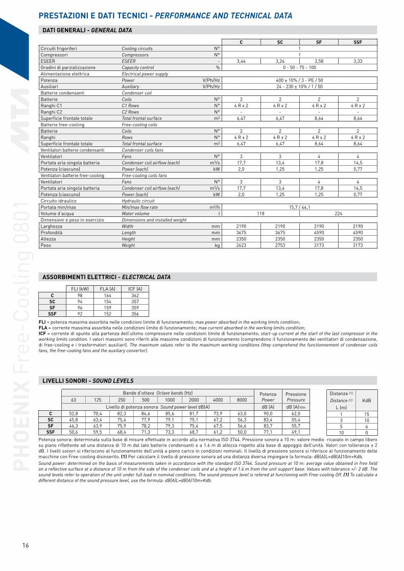
PRESTAZIONI E DATI TECNICI - PERFORMANCE AND TECHNICAL DATA DATI GENERALI - GENERAL DATA
C SC SF SSFCircuiti frigoriferi Cooling circuits N° 1Compressori Compressors N° 1ESEER ESEER - 3,44 3,24 3,58 3,33Gradini di parzializzazione Capacity control % 0 - 50 - 75 - 100Alimentazione elettrica Electrical power supplyPotenza Power V/Ph/Hz 400 ± 10% / 3 - PE / 50Ausiliari Auxiliary V/Ph/Hz 24 - 230 ± 10% / 1 / 50 Batterie condensanti Condenser coilBatterie Coils N° 2 2 2 2Ranghi C1 C1 Rows N° 4 R x 2 4 R x 2 4 R x 2 4 R x 2Ranghi C2 C2 Rows N° - - - -Superficie frontale totale Total frontal surface m2 6,47 6,47 8,64 8,64Batterie free-cooling Free-cooling coilsBatterie Coils N° 2 2 2 2Ranghi Rows N° 4 R x 2 4 R x 2 4 R x 2 4 R x 2Superficie frontale totale Total frontal surface m2 6,47 6,47 8,64 8,64Ventilatori batterie condensanti Condenser coils fansVentilatori Fans N° 3 3 4 4Portata aria singola batteria Condenser coil airflow (each) m3/s 17,7 13,4 17,8 14,5Potenza (ciascuno) Power (each) kW 2,0 1,25 1,25 0,77Ventilatori batterie free-cooling Free-cooling coils fansVentilatori Fans N° 3 3 4 4Portata aria singola batteria Condenser coil airflow (each) m3/s 17,7 13,4 17,8 14,5Potenza (ciascuno) Power (each) kW 2,0 1,25 1,25 0,77Circuito idraulico Hydraulic circuitPortata min/max Min/max flow rate m3/h 15,7 / 44,1Volume d'acqua Water volume l 118 224Dimensioni e peso in esercizio Dimensions and installed weightLarghezza Width mm 2190 2190 2190 2190Profondità Length mm 3675 3675 4590 4590Altezza Height mm 2350 2350 2350 2350Peso Weight kg 2623 2753 3173 3173
Distanza (1)
KdBDistance (1)
L (m)1 153 105 6
10 0
Bande d'ottava Octave bands (Hz) PotenzaPower
PressionePressure63 125 250 500 1000 2000 4000 8000
Livello di potenza sonora Sound power level dB(A) dB (A) dB (A)10m
C 52,8 70,4 82,3 84,6 85,6 81,7 73,9 63,0 90,0 62,0SC 45,8 63,4 75,4 77,9 79,1 75,1 67,2 56,3 83,4 55,4SF 46,3 63,9 75,9 78,2 79,3 75,4 67,5 56,6 83,7 55,7
SSF 50,6 59,5 68,4 71,3 73,3 68,7 61,2 50,0 77,1 49,1
LIVELLI SONORI - SOUND LEVELS
Potenza sonora: determinata sulla base di misure effettuate in accordo alla normativa ISO 3744. Pressione sonora a 10 m: valore medio ricavato in campo libero su piano riflettente ad una distanza di 10 m dal lato batterie condensanti e a 1.6 m di altezza rispetto alla base di appoggio dell’unità. Valori con tolleranza ± 2 dB. I livelli sonori si riferiscono al funzionamento dell’unità a pieno carico in condizioni nominali. Il livello di pressione sonora si riferisce al funzionamento delle macchine con Free-cooling disinserito. (1) Per calcolare il livello di pressione sonora ad una distanza diversa impiegare la formula: dB(A)L=dB(A)10m+Kdb. Sound power: determined on the basis of measurements taken in accordance with the standard ISO 3744. Sound pressure at 10 m: average value obtained in free field on a reflective surface at a distance of 10 m from the side of the condenser coils and at a height of 1.6 m from the unit support base. Values with tolerance +/- 2 dB. The sound levels refer to operation of the unit under full load in nominal conditions. The sound pressure level is refered at functioning with Free-cooling Off. (1) To calculate a different distance of the sound pressure level, use the formula: dB(A)L=dB(A)10m+Kdb.
FLI = potenza massima assorbita nelle condizioni limite di funzionamento; max power absorbed in the working limits condition; FLA = corrente massima assorbita nelle condizioni limite di funzionamento; max current absorbed in the working limits condition; ICF = corrente di spunto alla partenza dell’ultimo compressore nelle condizioni limite di funzionamento; start-up current at the start of the last compressor in the working limits condition. I valori massimi sono riferiti alle massime condizioni di funzionamento (comprendono il funzionamento dei ventilatori di condensazione, di free-cooling e i trasformatori ausiliari). The maximum values refer to the maximum working conditions (they comprehend the functionnement of condenser coils fans, the free-cooling fans and the auxiliary convertor).
ASSORBIMENTI ELETTRICI - ELECTRICAL DATA
FLI (kW) FLA (A) ICF (A)C 98 164 362
SC 94 154 357SF 96 159 359
SSF 92 152 356
PHO
ENIX
Fre
e-Co
olin
g 08
01

17
PHO
ENIX
Fre
e-Co
olin
g 08
01
PRESTAZIONI IN REFRIGERAZIONE - REFRIGERATION PERFORMANCES DATA
tu (°C)
Temperatura aria esterna - External air temperature ta (°C)t max.(*)
(°C)25 30 32 35 38 40
Pf Pa Fw Pf Pa Fw Pf Pa Fw Pf Pa Fw Pf Pa Fw Pf Pa Fw(kW) (kW) (m3/h) (kW) (kW) (m3/h) (kW) (kW) (m3/h) (kW) (kW) (m3/h) (kW) (kW) (m3/h) (kW) (kW) (m3/h)
C
5 183 53 35 171 58 33 167 60 32 159 63 30 151 67 29 146 69 28 466 189 54 36 177 59 34 172 61 33 165 64 31 156 67 30 151 70 29 457 195 55 37 183 60 35 178 62 34 170 65 32 162 68 31 156 71 30 458 201 56 38 189 61 36 184 63 35 176 66 33 167 69 32 161 72 31 459 208 57 40 195 62 37 190 64 36 181 67 35 173 70 33 167 73 32 44
10 214 58 41 201 63 38 196 65 37 187 68 36 178 72 34 172 74 33 4311 221 59 42 207 64 39 202 66 38 193 69 37 184 73 35 178 75 34 4312 228 60 43 214 65 41 208 67 40 199 70 38 190 74 36 184 76 35 4213 234 61 45 220 66 42 214 68 41 205 71 39 196 75 37 189 77 36 4214 241 62 46 227 67 43 221 69 42 211 73 40 202 76 38 195 78 37 4115 248 63 47 233 68 44 227 71 43 218 74 41 208 77 39 201 79 38 41
SC
5 173 57 33 161 62 31 157 64 30 149 67 28 141 70 27 136 72 26 436 179 58 34 167 63 32 162 65 31 154 68 29 146 71 28 140 73 27 427 184 59 35 172 64 33 167 66 32 159 69 30 151 72 29 145 75 28 428 190 60 36 177 65 34 172 67 33 164 70 31 156 73 30 150 76 29 419 196 61 37 183 66 35 177 68 34 169 71 32 161 75 31 155 77 29 40
10 202 62 38 189 67 36 183 69 35 174 72 33 166 76 32 160 78 30 4011 208 63 40 194 68 37 188 70 36 180 74 34 171 77 32 3912 214 64 41 200 70 38 194 72 37 185 75 35 176 78 33 3813 220 66 42 206 71 39 200 73 38 191 76 36 181 79 34 3814 226 67 43 212 72 40 206 74 39 196 77 37 3715 233 68 44 218 73 41 211 75 40 202 79 38 36
SF
5 188 52 36 176 56 34 171 59 33 164 62 31 156 65 30 150 67 29 476 194 52 37 182 57 35 177 59 34 169 63 32 161 66 31 156 68 30 477 200 53 38 188 58 36 183 60 35 175 63 33 167 67 32 161 69 31 468 207 54 39 194 59 37 189 61 36 181 64 34 172 68 33 167 70 32 469 213 55 41 200 60 38 195 62 37 187 65 36 178 69 34 172 71 33 46
10 220 56 42 207 61 39 201 63 38 193 66 37 184 70 35 178 72 34 4511 227 57 43 213 62 41 208 64 39 199 67 38 190 71 36 184 73 35 4512 234 58 44 220 63 42 214 65 41 205 68 39 196 72 37 190 74 36 4413 241 59 46 227 64 43 221 66 42 212 69 40 202 73 38 196 75 37 4414 248 60 47 234 65 44 227 67 43 218 70 41 208 74 40 202 76 38 4315 255 61 48 240 66 46 234 68 44 225 72 43 215 75 41 208 77 39 43
SSF
5 175 56 33 164 61 31 159 63 30 151 66 29 143 69 27 138 72 26 436 181 57 35 169 62 32 164 64 31 156 67 30 148 70 28 143 73 27 437 187 58 36 174 63 33 169 65 32 161 68 31 153 71 29 148 74 28 428 193 59 37 180 64 34 175 66 33 167 69 32 158 73 30 152 75 29 429 199 60 38 186 65 35 180 67 34 172 70 33 163 74 31 157 76 30 41
10 205 61 39 191 66 36 186 68 35 177 72 34 168 75 32 162 77 31 4011 211 62 40 197 67 37 191 69 36 183 73 35 174 76 33 167 78 32 4012 217 63 41 203 69 39 197 71 37 188 74 36 179 77 34 3913 223 65 42 209 70 40 203 72 39 194 75 37 184 78 35 3914 230 66 44 215 71 41 209 73 40 199 76 38 190 80 36 3815 236 67 45 221 72 42 215 74 41 205 77 39 37
PRESTAZIONI IN Free-cooling - Free-cooling PERFORMANCES DATA
tu (°C)
Temperatura aria esterna - External air temperature ta ext. (°C) Fw
(m3/h)
t FC Tot.
(°C)1 3 5 7 9
Pf FC (kW) Pf FC (kW) Pf FC (kW) Pf FC (kW) Pf FC (kW)
C
5 106 82 58 35 11 30 -3,46 118 94 70 47 23 31 -2,77 132 107 83 59 35 32 -2,18 145 120 95 71 47 33 -1,49 158 133 108 84 59 35 -0,8
10 172 146 121 96 72 36 -0,211 186 160 134 109 84 37 0,412 199 173 148 122 97 38 1,013 213 187 161 136 110 39 1,614 228 201 175 149 123 40 2,215 242 215 189 162 137 41 2,8
tu: temperatura acqua uscita evaporatore, evaporator outlet water temperature; Pf: potenza frigorifera, cooling capacity; Pa: potenza assorbita dai compressori, power absorbed by the compressors; Fw: portata d’acqua (∆T = 5 °C), water flow rate (∆T = 5 °C); Pf FC: resa frigorifera batteria free-cooling, cooling capacity of free-cooling coil; T FC Tot.: temperatura di free-cooling totale, total free-cooling temperature. É permessa l’interpolazione dei valori ma non la loro estrapolazione. Per la determinazione di Pf, Pa e Fw per ∆T diversi da 5 °C vedere la tabella ”Coefficienti correttivi per ∆T diversi da 5 °C”. Le prestazioni sono state calcolate con acqua glicolata al 30%. Le prestazioni in free-cooling fanno riferimento alle portate d’acqua del funzionamento in refrigerazione, alle condizioni di ta = 35 °C e in corrispondenza delle stesse temperature uscita acqua. I valori evidenziati in grigio sono relativi ad una portata d'acqua esterna ai limiti e non rappresentano un punto di funzionamento permesso. Tali valori sono riportati solamente per consentire l'interpolazione delle prestazioni ed eventualmente il calcolo con delta T diversi da 5 °C. (*):Temperatura massima ambiente. Se la temperatura aria esterna è superiore a t max. il refrigeratore non si blocca ma interviene il sistema “unloading” di parzializzazione. Interpolation is allowed, extrapolation is not permitted. To calculate Pf, Pa and Fw for ∆T ≠ 5 °C when examining the table ”Correction factors for ∆T ≠ 5 °C”. Cooling capacity refers to 30% Ethylene glycol in the water. Free-cooling performances refers to water flow rate at refrigeration functioning, at conditions of ta = 35 °C and in corrispondence of the same output water temperatures. Values highlighted in grey refer to water flows beyond the accepted limits, and as such do not represent permissible working conditions. The values have been shown merely to allow data interpolation and, if desired, as an aid towards calculations with temperature differences other than 5 °C. (*): When the external air temperature is higher than the tmax. the chiller doesn’t stop but the “unloading” system capacity control is activated.
SC
5 91 70 50 30 10 28 -4,56 102 81 60 40 20 29 -3,97 113 92 71 50 30 30 -3,38 124 103 82 61 40 31 -2,79 135 114 92 71 51 32 -2,1
10 147 125 103 82 61 33 -1,511 158 136 115 93 72 34 -0,912 170 148 126 104 83 35 -0,413 182 159 137 115 94 36 0,214 193 171 148 126 105 37 0,715 205 182 160 138 116 38 1,3
SF
5 108 83 59 35 12 31 -3,46 121 96 72 48 24 32 -2,87 135 110 85 60 36 33 -2,18 149 123 98 73 48 34 -1,59 163 137 111 86 61 36 -0,9
10 177 150 125 99 74 37 -0,211 191 165 138 112 87 38 0,412 206 179 152 126 100 39 1,013 220 193 166 140 114 40 1,614 235 208 181 154 127 41 2,315 250 223 195 168 141 43 2,9
SSF
5 96 74 53 31 10 29 -4,06 108 86 64 42 21 30 -3,37 120 97 75 53 32 31 -2,78 132 109 87 65 43 32 -2,09 144 121 98 76 54 33 -1,4
10 156 133 110 88 65 34 -0,811 169 145 122 99 77 35 -0,112 182 158 134 111 88 36 0,413 194 170 147 123 100 37 1,014 207 183 159 136 112 38 1,615 220 196 172 148 124 39 2,2

18
DATI GENERALI - GENERAL DATA
C SC SF SSFCircuiti frigoriferi Cooling circuits N° 1Compressori Compressors N° 1ESEER ESEER - 3,72 3,56 3,99 3,80Gradini di parzializzazione Capacity control % 0 - 50 - 75 - 100Alimentazione elettrica Electrical power supplyPotenza Power V/Ph/Hz 400 ± 10% / 3 - PE / 50Ausiliari Auxiliary V/Ph/Hz 24 - 230 ± 10% / 1 / 50 Batterie condensanti Condenser coilBatterie Coils N° 2 2 2 2Ranghi C1 C1 Rows N° 3 R x 2 3 R x 2 4 R x 2 4 R x 2Ranghi C2 C2 Rows N° - - - -Superficie frontale totale Total frontal surface m2 8,64 8,64 10,8 10,8Batterie free-cooling Free-cooling coilsBatterie Coils N° 2 2 2 2Ranghi Rows N° 3 R x 2 3 R x 2 4 R x 2 4 R x 2Superficie frontale totale Total frontal surface m2 8,64 8,64 10,2 10,2Ventilatori batterie condensanti Condenser coils fansVentilatori Fans N° 4 4 5 5Portata aria singola batteria Condenser coil airflow (each) m3/s 24,5 18,9 22,2 18,1Potenza (ciascuno) Power (each) kW 2,0 1,25 1,25 0,77Ventilatori batterie free-cooling Free-cooling coils fansVentilatori Fans N° 4 4 5 5Portata aria singola batteria Condenser coil airflow (each) m3/s 24,5 18,9 22,2 18,1Potenza (ciascuno) Power (each) kW 2,0 1,25 1,25 0,77Circuito idraulico Hydraulic circuitPortata min/max Min/max flow rate m3/h 19,9 / 63,0Volume d'acqua Water volume l 226 293Dimensioni e peso in esercizio Dimensions and installed weightLarghezza Width mm 2190 2190 2190 2190Profondità Length mm 4590 4590 5490 5490Altezza Height mm 2350 2350 2350 2350Peso Weight kg 3306 3436 3903 3903
Distanza (1)
KdBDistance (1)
L (m)1 153 105 6
10 0
Bande d'ottava Octave bands (Hz) PotenzaPower
PressionePressure63 125 250 500 1000 2000 4000 8000
Livello di potenza sonora Sound power level dB(A) dB (A) dB (A)10m
C 54,3 71,9 83,8 86,6 85,7 82,8 74,5 64,2 91,2 63,2SC 47,1 64,7 76,7 80,0 78,9 75,9 67,6 57,3 84,3 56,3SF 46,7 64,3 76,3 79,8 78,6 75,7 67,3 57,0 84,1 56,1
SSF 50,9 59,9 68,9 73,3 72,3 68,9 60,6 50,3 77,5 49,5
LIVELLI SONORI - SOUND LEVELS
Potenza sonora: determinata sulla base di misure effettuate in accordo alla normativa ISO 3744. Pressione sonora a 10 m: valore medio ricavato in campo libero su piano riflettente ad una distanza di 10 m dal lato batterie condensanti e a 1.6 m di altezza rispetto alla base di appoggio dell’unità. Valori con tolleranza ± 2 dB. I livelli sonori si riferiscono al funzionamento dell’unità a pieno carico in condizioni nominali. Il livello di pressione sonora si riferisce al funzionamento delle macchine con Free-cooling disinserito. (1) Per calcolare il livello di pressione sonora ad una distanza diversa impiegare la formula: dB(A)L=dB(A)10m+Kdb. Sound power: determined on the basis of measurements taken in accordance with the standard ISO 3744. Sound pressure at 10 m: average value obtained in free field on a reflective surface at a distance of 10 m from the side of the condenser coils and at a height of 1.6 m from the unit support base. Values with tolerance +/- 2 dB. The sound levels refer to operation of the unit under full load in nominal conditions. The sound pressure level is refered at functioning with Free-cooling Off. (1) To calculate a different distance of the sound pressure level, use the formula: dB(A)L=dB(A)10m+Kdb.
FLI = potenza massima assorbita nelle condizioni limite di funzionamento; max power absorbed in the working limits condition; FLA = corrente massima assorbita nelle condizioni limite di funzionamento; max current absorbed in the working limits condition; ICF = corrente di spunto alla partenza dell’ultimo compressore nelle condizioni limite di funzionamento; start-up current at the start of the last compressor in the working limits condition. I valori massimi sono riferiti alle massime condizioni di funzionamento (comprendono il funzionamento dei ventilatori di condensazione, di free-cooling e i trasformatori ausiliari). The maximum values refer to the maximum working conditions (they comprehend the functionnement of condenser coils fans, the free-cooling fans and the auxiliary convertor).
ASSORBIMENTI ELETTRICI - ELECTRICAL DATA
FLI (kW) FLA (A) ICF (A)C 116 198 439
SC 110 185 432SF 112 189 435
SSF 108 181 431
PHO
ENIX
Fre
e-Co
olin
g 09
01

19
PRESTAZIONI IN REFRIGERAZIONE - REFRIGERATION PERFORMANCES DATA
tu (°C)
Temperatura aria esterna - External air temperature ta (°C)t max.(*)
(°C)25 30 32 35 38 40
Pf Pa Fw Pf Pa Fw Pf Pa Fw Pf Pa Fw Pf Pa Fw Pf Pa Fw(kW) (kW) (m3/h) (kW) (kW) (m3/h) (kW) (kW) (m3/h) (kW) (kW) (m3/h) (kW) (kW) (m3/h) (kW) (kW) (m3/h)
C
5 212 60 40 199 66 38 194 69 37 186 73 35 177 77 34 172 81 33 456 219 61 42 206 67 39 200 70 38 192 74 37 183 79 35 177 82 34 457 226 62 43 212 68 41 207 71 39 198 75 38 189 80 36 183 83 35 448 233 63 44 219 69 42 214 72 41 205 76 39 196 81 37 189 84 36 449 240 64 46 226 70 43 220 73 42 211 77 40 202 82 38 195 85 37 43
10 248 65 47 233 72 44 227 74 43 218 79 41 208 83 40 202 87 38 4311 255 67 49 240 73 46 234 75 45 225 80 43 215 84 41 208 88 40 4212 263 68 50 248 74 47 241 77 46 231 81 44 221 86 42 214 89 41 4213 271 69 51 255 75 48 248 78 47 238 82 45 228 87 43 221 90 42 4114 279 70 53 262 77 50 256 79 49 245 84 47 235 88 45 227 92 43 4115 287 72 54 270 78 51 263 81 50 252 85 48 241 90 46 234 93 44 40
SC
5 201 64 38 188 71 36 183 74 35 175 78 33 166 83 32 160 87 31 426 207 66 40 194 72 37 189 75 36 180 79 34 172 84 33 166 88 32 417 214 67 41 200 73 38 195 76 37 186 81 35 177 86 34 171 89 33 418 220 68 42 206 75 39 201 77 38 192 82 37 183 87 35 177 91 34 409 227 69 43 213 76 41 207 79 39 198 83 38 188 88 36 182 92 35 40
10 234 70 44 219 77 42 213 80 41 204 85 39 194 90 37 3911 241 72 46 226 79 43 219 81 42 210 86 40 200 91 38 3812 247 73 47 232 80 44 226 83 43 216 88 41 206 93 39 3813 255 75 48 239 81 45 232 84 44 222 89 42 3714 262 76 50 245 83 47 239 86 45 229 91 43 3615 269 78 51 252 84 48 245 87 47 235 92 45 36
SF
5 221 57 42 209 62 40 203 65 39 195 69 37 187 73 36 181 76 35 486 229 58 44 216 63 41 210 66 40 202 70 39 193 74 37 187 77 36 487 236 58 45 223 64 42 217 67 41 209 71 40 200 75 38 194 78 37 478 244 59 46 230 65 44 224 68 43 215 72 41 206 76 39 200 79 38 479 252 60 48 238 66 45 232 69 44 222 73 42 213 77 41 207 80 39 46
10 260 61 49 245 67 47 239 70 45 230 74 44 220 78 42 213 81 41 4611 268 62 51 253 68 48 247 71 47 237 75 45 227 79 43 220 82 42 4612 276 63 52 261 69 50 254 72 48 244 76 46 234 80 45 227 83 43 4513 285 65 54 269 70 51 262 73 50 252 77 48 242 81 46 234 85 45 4514 293 66 56 277 72 53 270 74 51 259 78 49 249 83 47 242 86 46 4415 302 67 57 285 73 54 278 75 53 267 79 51 256 84 49 249 87 47 44
SSF
5 209 61 40 196 67 37 191 70 36 182 74 35 174 79 33 168 82 32 446 215 62 41 202 69 39 197 71 38 188 76 36 180 80 34 174 84 33 447 222 63 42 209 70 40 203 72 39 194 77 37 186 81 35 180 85 34 438 229 65 44 215 71 41 210 73 40 201 78 38 192 83 37 185 86 35 439 236 66 45 222 72 42 216 75 41 207 79 39 198 84 38 191 87 36 42
10 243 67 46 229 73 44 223 76 42 214 80 41 204 85 39 197 88 38 4211 251 68 48 236 74 45 230 77 44 220 82 42 210 86 40 204 90 39 4112 258 69 49 243 76 46 236 78 45 227 83 43 217 88 41 210 91 40 4113 266 71 50 250 77 47 243 80 46 233 84 44 223 89 42 216 92 41 4014 274 72 52 257 78 49 250 81 48 240 86 46 230 90 44 3915 281 73 53 265 80 50 258 83 49 247 87 47 236 92 45 39
PRESTAZIONI IN Free-cooling - Free-cooling PERFORMANCES DATA
tu (°C)
Temperatura aria esterna - External air temperature ta ext. (°C) Fw
(m3/h)
t FC Tot.
(°C)1 3 5 7 9
Pf FC (kW) Pf FC (kW) Pf FC (kW) Pf FC (kW) Pf FC (kW)
C
5 112 86 61 37 12 35 -4,76 125 100 74 49 24 37 -4,17 139 113 88 62 37 38 -3,48 153 127 101 75 50 39 -2,89 168 141 115 89 63 40 -2,2
10 183 155 129 102 76 41 -1,611 197 170 143 116 90 43 -1,012 212 185 157 130 104 44 -0,313 228 200 172 145 118 45 0,314 243 215 187 159 132 47 0,915 259 230 202 174 146 48 1,4
tu: temperatura acqua uscita evaporatore, evaporator outlet water temperature; Pf: potenza frigorifera, cooling capacity; Pa: potenza assorbita dai compressori, power absorbed by the compressors; Fw: portata d’acqua (∆T = 5 °C), water flow rate (∆T = 5 °C); Pf FC: resa frigorifera batteria free-cooling, cooling capacity of free-cooling coil; T FC Tot.: temperatura di free-cooling totale, total free-cooling temperature. É permessa l’interpolazione dei valori ma non la loro estrapolazione. Per la determinazione di Pf, Pa e Fw per ∆T diversi da 5 °C vedere la tabella ”Coefficienti correttivi per ∆T diversi da 5 °C”. Le prestazioni sono state calcolate con acqua glicolata al 30%. Le prestazioni in free-cooling fanno riferimento alle portate d’acqua del funzionamento in refrigerazione, alle condizioni di ta = 35 °C e in corrispondenza delle stesse temperature uscita acqua. I valori evidenziati in grigio sono relativi ad una portata d'acqua esterna ai limiti e non rappresentano un punto di funzionamento permesso. Tali valori sono riportati solamente per consentire l'interpolazione delle prestazioni ed eventualmente il calcolo con delta T diversi da 5 °C. (*):Temperatura massima ambiente. Se la temperatura aria esterna è superiore a t max. il refrigeratore non si blocca ma interviene il sistema “unloading” di parzializzazione. Interpolation is allowed, extrapolation is not permitted. To calculate Pf, Pa and Fw for ∆T ≠ 5 °C when examining the table ”Correction factors for ∆T ≠ 5 °C”. Cooling capacity refers to 30% Ethylene glycol in the water. Free-cooling performances refers to water flow rate at refrigeration functioning, at conditions of ta = 35 °C and in corrispondence of the same output water temperatures. Values highlighted in grey refer to water flows beyond the accepted limits, and as such do not represent permissible working conditions. The values have been shown merely to allow data interpolation and, if desired, as an aid towards calculations with temperature differences other than 5 °C. (*): When the external air temperature is higher than the tmax. the chiller doesn’t stop but the “unloading” system capacity control is activated.
SC
5 99 77 54 32 11 33 -5,66 111 88 66 44 22 34 -4,97 123 100 78 55 33 35 -4,38 136 112 89 67 44 37 -3,79 148 125 101 78 56 38 -3,1
10 161 137 114 90 67 39 -2,511 174 150 126 102 79 40 -1,912 187 163 139 115 91 41 -1,313 200 176 151 127 103 42 -0,714 214 189 164 140 116 43 -0,215 227 202 177 152 128 45 0,4
SF
5 136 105 74 44 15 37 -2,86 152 121 90 60 30 39 -2,17 169 138 106 76 45 40 -1,48 187 155 123 92 61 41 -0,89 204 172 140 108 77 42 -0,1
10 222 189 156 124 93 44 0,511 240 206 174 141 109 45 1,212 258 224 191 158 126 46 1,813 276 242 209 175 143 48 2,414 295 260 226 193 160 49 3,015 314 279 245 211 177 51 3,7
SSF
5 121 94 66 40 13 35 -3,46 136 108 80 53 26 36 -2,77 151 122 95 67 40 37 -2,18 166 137 109 81 54 38 -1,49 181 152 124 96 68 39 -0,8
10 197 167 139 110 82 41 -0,111 212 183 154 125 97 42 0,512 228 198 169 140 111 43 1,113 244 214 184 155 126 44 1,714 260 230 200 170 141 46 2,315 276 246 215 186 156 47 2,9
PHO
ENIX
Fre
e-Co
olin
g 09
01

20
DATI GENERALI - GENERAL DATA
C SC SF SSFCircuiti frigoriferi Cooling circuits N° 1Compressori Compressors N° 1ESEER ESEER - 3,63 3,35 3,93 3,68Gradini di parzializzazione Capacity control % 0 - 50 - 75 - 100Alimentazione elettrica Electrical power supplyPotenza Power V/Ph/Hz 400 ± 10% / 3 - PE / 50Ausiliari Auxiliary V/Ph/Hz 24 - 230 ± 10% / 1 / 50 Batterie condensanti Condenser coilBatterie Coils N° 2 2 2 2Ranghi C1 C1 Rows N° 4 R x 2 4 R x 2 4 R x 2 4 R x 2Ranghi C2 C2 Rows N° - - - -Superficie frontale totale Total frontal surface m2 8,64 8,64 13,0 13,0Batterie free-cooling Free-cooling coilsBatterie Coils N° 2 2 2 2Ranghi Rows N° 4 R x 2 4 R x 2 4 R x 2 4 R x 2Superficie frontale totale Total frontal surface m2 8,64 8,64 13,0 13,0Ventilatori batterie condensanti Condenser coils fansVentilatori Fans N° 4 4 6 6Portata aria singola batteria Condenser coil airflow (each) m3/s 23,5 17,8 26,7 21,7Potenza (ciascuno) Power (each) kW 2,0 1,25 1,25 0,77Ventilatori batterie free-cooling Free-cooling coils fansVentilatori Fans N° 4 4 6 6Portata aria singola batteria Condenser coil airflow (each) m3/s 23,5 17,8 26,7 21,7Potenza (ciascuno) Power (each) kW 2,0 1,25 1,25 0,77Circuito idraulico Hydraulic circuitPortata min/max Min/max flow rate m3/h 24,8 / 63,0Volume d'acqua Water volume l 263 327Dimensioni e peso in esercizio Dimensions and installed weightLarghezza Width mm 2190 2190 2190 2190Profondità Length mm 4590 4590 6425 6425Altezza Height mm 2350 2350 2350 2350Peso Weight kg 3814 3974 4738 4738
Distanza (1)
KdBDistance (1)
L (m)1 153 105 6
10 0
Bande d'ottava Octave bands (Hz) PotenzaPower
PressionePressure63 125 250 500 1000 2000 4000 8000
Livello di potenza sonora Sound power level dB(A) dB (A) dB (A)10m
C 53,7 70,9 82,4 84,9 86,9 81,2 73,3 62,8 90,6 62,6SC 46,8 63,9 75,5 78,3 80,5 74,4 66,5 55,9 84,0 56,0SF 47,3 64,5 76,0 78,7 80,7 74,9 67,0 56,4 84,3 56,3
SSF 51,2 60,2 68,2 71,7 74,9 67,5 59,9 48,8 77,8 49,8
LIVELLI SONORI - SOUND LEVELS
Potenza sonora: determinata sulla base di misure effettuate in accordo alla normativa ISO 3744. Pressione sonora a 10 m: valore medio ricavato in campo libero su piano riflettente ad una distanza di 10 m dal lato batterie condensanti e a 1.6 m di altezza rispetto alla base di appoggio dell’unità. Valori con tolleranza ± 2 dB. I livelli sonori si riferiscono al funzionamento dell’unità a pieno carico in condizioni nominali. Il livello di pressione sonora si riferisce al funzionamento delle macchine con Free-cooling disinserito. (1) Per calcolare il livello di pressione sonora ad una distanza diversa impiegare la formula: dB(A)L=dB(A)10m+Kdb. Sound power: determined on the basis of measurements taken in accordance with the standard ISO 3744. Sound pressure at 10 m: average value obtained in free field on a reflective surface at a distance of 10 m from the side of the condenser coils and at a height of 1.6 m from the unit support base. Values with tolerance +/- 2 dB. The sound levels refer to operation of the unit under full load in nominal conditions. The sound pressure level is refered at functioning with Free-cooling Off. (1) To calculate a different distance of the sound pressure level, use the formula: dB(A)L=dB(A)10m+Kdb.
FLI = potenza massima assorbita nelle condizioni limite di funzionamento; max power absorbed in the working limits condition; FLA = corrente massima assorbita nelle condizioni limite di funzionamento; max current absorbed in the working limits condition; ICF = corrente di spunto alla partenza dell’ultimo compressore nelle condizioni limite di funzionamento; start-up current at the start of the last compressor in the working limits condition. I valori massimi sono riferiti alle massime condizioni di funzionamento (comprendono il funzionamento dei ventilatori di condensazione, di free-cooling e i trasformatori ausiliari). The maximum values refer to the maximum working conditions (they comprehend the functionnement of condenser coils fans, the free-cooling fans and the auxiliary convertor).
ASSORBIMENTI ELETTRICI - ELECTRICAL DATA
FLI (kW) FLA (A) ICF (A)C 133 223 635
SC 127 210 628SF 132 219 633
SSF 126 209 628
PHO
ENIX
Fre
e-Co
olin
g 11
01

21
PRESTAZIONI IN REFRIGERAZIONE - REFRIGERATION PERFORMANCES DATA
tu (°C)
Temperatura aria esterna - External air temperature ta (°C)t max.(*)
(°C)25 30 32 35 38 40
Pf Pa Fw Pf Pa Fw Pf Pa Fw Pf Pa Fw Pf Pa Fw Pf Pa Fw(kW) (kW) (m3/h) (kW) (kW) (m3/h) (kW) (kW) (m3/h) (kW) (kW) (m3/h) (kW) (kW) (m3/h) (kW) (kW) (m3/h)
C
5 259 72 49 242 78 46 235 81 45 224 85 43 212 90 41 205 94 39 456 267 73 51 250 80 48 243 82 46 232 87 44 220 92 42 212 95 40 457 276 74 53 258 81 49 251 84 48 239 88 46 228 93 43 219 97 42 448 285 76 54 267 82 51 259 85 49 248 90 47 235 95 45 227 98 43 439 294 77 56 276 84 52 268 86 51 256 91 49 243 96 46 235 100 45 43
10 303 78 58 284 85 54 276 88 53 264 93 50 251 98 48 243 101 46 4211 313 80 60 293 87 56 285 90 54 273 94 52 260 99 49 251 103 48 4212 323 81 61 303 88 58 294 91 56 281 96 53 268 101 51 259 105 49 4113 332 83 63 312 90 59 303 93 58 290 98 55 277 103 53 267 106 51 4114 342 84 65 321 91 61 313 94 59 299 99 57 285 105 54 276 108 52 4015 352 86 67 331 93 63 322 96 61 308 101 58 294 106 56 39
SC
5 244 77 47 226 83 43 219 86 42 208 91 40 197 96 38 189 100 36 426 252 78 48 234 85 45 227 88 43 215 93 41 204 98 39 196 102 37 417 260 79 49 242 86 46 234 90 45 223 94 42 211 100 40 203 104 39 408 268 81 51 249 88 47 242 91 46 230 96 44 218 101 41 210 105 40 409 276 83 53 257 90 49 249 93 47 237 98 45 225 103 43 39
10 284 84 54 265 91 50 257 94 49 245 100 47 232 105 44 3811 293 86 56 273 93 52 265 96 50 253 101 48 240 107 46 3812 302 88 57 281 95 53 273 98 52 260 103 49 3713 310 89 59 290 97 55 281 100 53 268 105 51 3614 319 91 61 298 99 57 290 102 55 276 107 52 3515 328 93 62 307 101 58 298 104 57 284 109 54 35
SF
5 274 68 52 257 73 49 250 76 48 239 80 46 227 85 43 220 88 42 486 283 69 54 266 75 51 259 77 49 247 81 47 236 86 45 228 89 43 487 292 70 56 275 76 52 267 78 51 256 83 49 244 87 47 236 90 45 478 302 71 58 284 77 54 277 79 53 265 84 50 253 88 48 244 92 47 479 312 72 59 294 78 56 286 81 54 274 85 52 262 90 50 253 93 48 47
10 322 73 61 303 79 58 295 82 56 283 86 54 271 91 51 262 94 50 4611 333 74 63 313 81 60 305 83 58 293 88 56 280 92 53 271 96 51 4612 343 76 65 323 82 61 315 85 60 302 89 57 289 94 55 280 97 53 4513 354 77 67 334 83 63 325 86 62 312 91 59 298 95 57 289 99 55 4514 365 78 69 344 85 65 335 88 64 322 92 61 308 97 58 299 100 57 4415 376 80 71 355 86 67 346 89 66 332 94 63 318 99 60 308 102 58 43
SSF
5 257 73 49 240 79 46 233 82 44 222 86 42 211 91 40 203 95 39 456 265 74 51 248 80 47 241 83 46 229 88 44 218 93 42 210 96 40 447 274 75 52 256 82 49 249 84 47 237 89 45 226 94 43 217 98 41 448 283 76 54 265 83 50 257 86 49 245 90 47 233 95 44 225 99 43 439 292 78 56 273 84 52 266 87 51 254 92 48 241 97 46 233 101 44 42
10 301 79 57 282 86 54 274 89 52 262 94 50 249 99 47 240 102 46 4211 311 81 59 291 87 55 283 90 54 270 95 51 257 100 49 248 104 47 4112 320 82 61 300 89 57 292 92 55 279 97 53 266 102 50 256 106 49 4113 330 84 63 309 91 59 301 94 57 288 99 55 274 104 52 265 108 50 4014 340 85 64 319 92 60 310 95 59 296 100 56 283 106 54 3915 350 87 66 328 94 62 319 97 61 305 102 58 291 108 55 38
PRESTAZIONI IN Free-cooling - Free-cooling PERFORMANCES DATA
tu (°C)
Temperatura aria esterna - External air temperature ta ext. (°C) Fw
(m3/h)
t FC Tot.
(°C)1 3 5 7 9
Pf FC (kW) Pf FC (kW) Pf FC (kW) Pf FC (kW) Pf FC (kW)
C
5 132 102 72 43 14 43 -5,06 148 118 88 58 29 44 -4,47 165 134 104 73 44 46 -3,78 181 150 119 89 59 47 -3,19 198 167 136 105 74 49 -2,6
10 216 184 152 121 90 50 -2,011 233 201 169 137 106 52 -1,412 251 218 186 154 122 53 -0,913 269 235 203 170 139 55 -0,314 287 253 220 187 155 57 0,315 305 271 238 205 172 58 0,8
tu: temperatura acqua uscita evaporatore, evaporator outlet water temperature; Pf: potenza frigorifera, cooling capacity; Pa: potenza assorbita dai compressori, power absorbed by the compressors; Fw: portata d’acqua (∆T = 5 °C), water flow rate (∆T = 5 °C); Pf FC: resa frigorifera batteria free-cooling, cooling capacity of free-cooling coil; T FC Tot.: temperatura di free-cooling totale, total free-cooling temperature. É permessa l’interpolazione dei valori ma non la loro estrapolazione. Per la determinazione di Pf, Pa e Fw per ∆T diversi da 5 °C vedere la tabella ”Coefficienti correttivi per ∆T diversi da 5 °C”. Le prestazioni sono state calcolate con acqua glicolata al 30%. Le prestazioni in free-cooling fanno riferimento alle portate d’acqua del funzionamento in refrigerazione, alle condizioni di ta = 35 °C e in corrispondenza delle stesse temperature uscita acqua. I valori evidenziati in grigio sono relativi ad una portata d'acqua esterna ai limiti e non rappresentano un punto di funzionamento permesso. Tali valori sono riportati solamente per consentire l'interpolazione delle prestazioni ed eventualmente il calcolo con delta T diversi da 5 °C. (*):Temperatura massima ambiente. Se la temperatura aria esterna è superiore a t max. il refrigeratore non si blocca ma interviene il sistema “unloading” di parzializzazione. Interpolation is allowed, extrapolation is not permitted. To calculate Pf, Pa and Fw for ∆T ≠ 5 °C when examining the table ”Correction factors for ∆T ≠ 5 °C”. Cooling capacity refers to 30% Ethylene glycol in the water. Free-cooling performances refers to water flow rate at refrigeration functioning, at conditions of ta = 35 °C and in corrispondence of the same output water temperatures. Values highlighted in grey refer to water flows beyond the accepted limits, and as such do not represent permissible working conditions. The values have been shown merely to allow data interpolation and, if desired, as an aid towards calculations with temperature differences other than 5 °C. (*): When the external air temperature is higher than the tmax. the chiller doesn’t stop but the “unloading” system capacity control is activated.
SC
5 114 88 63 37 12 40 -6,16 128 102 76 50 25 41 -5,57 142 115 89 63 38 42 -4,98 156 129 103 77 51 44 -4,49 170 143 117 90 64 45 -3,8
10 185 158 130 104 77 47 -3,311 200 172 145 118 91 48 -2,712 215 186 159 131 105 49 -2,213 229 201 173 146 118 51 -1,714 245 216 188 160 132 52 -1,215 260 231 202 174 147 54 -0,7
SF
5 167 129 92 55 18 46 -2,76 188 149 111 74 37 47 -2,17 209 170 131 93 56 49 -1,48 230 190 151 113 75 50 -0,89 251 211 172 133 94 52 -0,1
10 273 232 192 153 114 54 0,511 295 254 213 174 134 56 1,112 317 276 235 194 155 57 1,713 340 298 256 216 175 59 2,314 362 320 278 237 196 61 2,915 385 342 300 259 217 63 3,5
SSF
5 149 115 82 49 16 42 -3,36 167 133 99 65 33 44 -2,67 185 150 116 83 49 45 -2,08 204 169 134 100 66 47 -1,49 222 187 152 117 83 48 -0,7
10 241 205 170 135 101 50 -0,111 260 224 189 153 118 51 0,412 280 243 207 171 136 53 1,013 299 262 226 190 154 55 1,614 319 282 245 209 173 56 2,215 339 301 264 227 191 58 2,8
PHO
ENIX
Fre
e-Co
olin
g110
1

22
DATI GENERALI - GENERAL DATA
C SC SF SSFCircuiti frigoriferi Cooling circuits N° 1Compressori Compressors N° 1ESEER ESEER - 3,60 3,41 3,80 3,58Gradini di parzializzazione Capacity control % 0 - 50 - 75 - 100Alimentazione elettrica Electrical power supplyPotenza Power V/Ph/Hz 400 ± 10% / 3 - PE / 50Ausiliari Auxiliary V/Ph/Hz 24 - 230 ± 10% / 1 / 50 Batterie condensanti Condenser coilBatterie Coils N° 2 2 2 2Ranghi C1 C1 Rows N° 4 R x 2 4 R x 2 4 R x 2 4 R x 2Ranghi C2 C2 Rows N° - - - -Superficie frontale totale Total frontal surface m2 10,8 10,8 15,2 15,2Batterie free-cooling Free-cooling coilsBatterie Coils N° 2 2 2 2Ranghi Rows N° 4 R x 2 4 R x 2 4 R x 2 4 R x 2Superficie frontale totale Total frontal surface m2 10,8 10,8 15,2 15,2Ventilatori batterie condensanti Condenser coils fansVentilatori Fans N° 5 5 7 7Portata aria singola batteria Condenser coil airflow (each) m3/s 29,2 22,2 31,1 25,3Potenza (ciascuno) Power (each) kW 2,0 1,25 1,25 0,77Ventilatori batterie free-cooling Free-cooling coils fansVentilatori Fans N° 5 5 7 7Portata aria singola batteria Condenser coil airflow (each) m3/s 29,2 22,2 31,1 25,3Potenza (ciascuno) Power (each) kW 2,0 1,25 1,25 0,77Circuito idraulico Hydraulic circuitPortata min/max Min/max flow rate m3/h 29,3 / 69,5Volume d'acqua Water volume l 287 352Dimensioni e peso in esercizio Dimensions and installed weightLarghezza Width mm 2190 2190 2190 2190Profondità Length mm 5490 5490 7360 7360Altezza Height mm 2350 2350 2350 2350Peso Weight kg 4648 4863 5525 5525
Distanza (1)
KdBDistance (1)
L (m)1 153 105 6
10 0
Bande d'ottava Octave bands (Hz) PotenzaPower
PressionePressure63 125 250 500 1000 2000 4000 8000
Livello di potenza sonora Sound power level dB(A) dB (A) dB (A)10m
C 53,7 71,3 82,8 86,4 87,9 81,9 73,7 63,1 91,6 63,6SC 46,7 64,3 75,8 79,9 81,6 75,1 66,9 56,3 85,0 57,0SF 47,1 64,7 76,2 80,1 81,7 75,4 67,2 56,6 85,2 57,2
SSF 51,1 60,1 68,1 73,3 75,6 68,0 59,9 48,7 78,6 50,6
LIVELLI SONORI - SOUND LEVELS
Potenza sonora: determinata sulla base di misure effettuate in accordo alla normativa ISO 3744. Pressione sonora a 10 m: valore medio ricavato in campo libero su piano riflettente ad una distanza di 10 m dal lato batterie condensanti e a 1.6 m di altezza rispetto alla base di appoggio dell’unità. Valori con tolleranza ± 2 dB. I livelli sonori si riferiscono al funzionamento dell’unità a pieno carico in condizioni nominali. Il livello di pressione sonora si riferisce al funzionamento delle macchine con Free-cooling disinserito. (1) Per calcolare il livello di pressione sonora ad una distanza diversa impiegare la formula: dB(A)L=dB(A)10m+Kdb. Sound power: determined on the basis of measurements taken in accordance with the standard ISO 3744. Sound pressure at 10 m: average value obtained in free field on a reflective surface at a distance of 10 m from the side of the condenser coils and at a height of 1.6 m from the unit support base. Values with tolerance +/- 2 dB. The sound levels refer to operation of the unit under full load in nominal conditions. The sound pressure level is refered at functioning with Free-cooling Off. (1) To calculate a different distance of the sound pressure level, use the formula: dB(A)L=dB(A)10m+Kdb.
FLI = potenza massima assorbita nelle condizioni limite di funzionamento; max power absorbed in the working limits condition; FLA = corrente massima assorbita nelle condizioni limite di funzionamento; max current absorbed in the working limits condition; ICF = corrente di spunto alla partenza dell’ultimo compressore nelle condizioni limite di funzionamento; start-up current at the start of the last compressor in the working limits condition. I valori massimi sono riferiti alle massime condizioni di funzionamento (comprendono il funzionamento dei ventilatori di condensazione, di free-cooling e i trasformatori ausiliari). The maximum values refer to the maximum working conditions (they comprehend the functionnement of condenser coils fans, the free-cooling fans and the auxiliary convertor).
ASSORBIMENTI ELETTRICI - ELECTRICAL DATA
FLI (kW) FLA (A) ICF (A)C 154 259 749
SC 146 242 741SF 151 251 745
SSF 145 240 740
PHO
ENIX
Fre
e-Co
olin
g 12
51

23
PRESTAZIONI IN REFRIGERAZIONE - REFRIGERATION PERFORMANCES DATA
tu (°C)
Temperatura aria esterna - External air temperature ta (°C)t max.(*)
(°C)25 30 32 35 38 40
Pf Pa Fw Pf Pa Fw Pf Pa Fw Pf Pa Fw Pf Pa Fw Pf Pa Fw(kW) (kW) (m3/h) (kW) (kW) (m3/h) (kW) (kW) (m3/h) (kW) (kW) (m3/h) (kW) (kW) (m3/h) (kW) (kW) (m3/h)
C
5 299 82 57 280 90 54 272 93 52 260 98 50 247 103 47 239 106 46 476 309 84 59 290 91 55 282 94 54 269 99 51 256 104 49 247 108 47 467 319 85 61 299 93 57 291 96 55 278 101 53 265 106 50 256 109 49 458 329 86 63 309 94 59 301 97 57 287 102 55 274 107 52 264 111 50 459 340 88 65 319 96 61 310 99 59 297 104 56 283 109 54 273 112 52 44
10 350 90 67 329 97 63 320 101 61 306 105 58 292 111 56 282 114 54 4411 361 91 69 339 99 65 330 102 63 316 107 60 301 112 57 291 116 55 4312 372 93 71 350 100 66 340 104 65 326 109 62 311 114 59 301 117 57 4313 383 94 73 360 102 68 350 105 67 336 110 64 320 115 61 310 119 59 4214 394 96 75 371 104 70 361 107 69 346 112 66 330 0117 63 320 121 61 4215 406 98 77 382 106 72 372 109 70 356 114 68 340 119 65 329 122 62 41
SC
5 284 88 54 264 95 50 257 98 49 244 103 47 231 108 44 223 112 43 436 293 89 56 273 97 52 265 100 51 252 105 48 239 110 46 230 113 44 437 302 91 58 282 99 54 273 102 52 261 107 50 247 112 47 238 115 45 428 311 92 59 291 100 55 282 103 54 269 108 51 255 113 49 246 117 47 429 321 94 61 300 102 57 291 105 55 278 110 53 264 115 50 254 118 48 41
10 330 96 63 309 104 59 300 107 57 286 112 54 272 117 52 262 120 50 4011 340 98 65 318 105 61 309 109 59 295 114 56 280 119 53 271 122 51 4012 350 99 67 328 107 62 318 110 61 304 115 58 289 120 55 3913 361 101 68 337 109 64 328 112 62 313 117 59 298 122 57 3814 371 103 70 347 111 66 337 114 64 322 119 61 306 124 58 3815 381 105 72 357 113 68 347 116 66 331 121 63 37
SF
5 310 79 59 292 86 56 284 89 54 272 94 52 259 99 49 250 102 48 496 321 80 61 302 87 58 294 90 56 281 95 54 268 100 51 259 104 49 487 331 81 63 312 89 59 303 92 58 291 97 55 277 102 53 268 105 51 488 342 82 65 322 90 61 313 93 60 300 98 57 287 103 55 277 107 53 479 353 84 67 333 91 63 324 95 62 310 100 59 296 105 56 287 108 55 47
10 365 85 69 343 93 65 334 96 64 321 101 61 306 106 58 296 110 56 4611 376 87 71 354 94 67 345 98 66 331 103 63 316 108 60 306 111 58 4612 388 88 74 365 96 69 356 99 68 341 104 65 326 109 62 316 113 60 4513 399 90 76 376 97 72 367 101 70 352 106 67 337 111 64 326 114 62 4514 412 91 78 388 99 74 378 102 72 363 107 69 347 112 66 337 116 64 4415 424 93 80 400 101 76 390 104 74 374 109 71 358 114 68 347 117 66 44
SSF
5 292 85 56 273 92 52 265 96 51 252 101 48 240 106 46 231 109 44 456 301 86 57 282 94 54 273 97 52 261 102 50 248 107 47 239 110 46 447 311 88 59 291 96 55 282 99 54 270 104 51 256 109 49 247 112 47 448 321 89 61 300 97 57 292 100 56 278 105 53 265 110 50 255 114 49 439 331 91 63 310 99 59 301 102 57 287 107 55 273 112 52 264 115 50 43
10 341 93 65 319 100 61 310 104 59 296 109 56 282 114 54 272 117 52 4211 351 94 67 329 102 63 320 105 61 306 110 58 291 115 55 281 119 53 4212 361 96 69 339 104 64 329 107 63 315 112 60 300 117 57 290 121 55 4113 372 98 71 349 106 66 339 109 64 325 114 62 309 119 59 299 122 57 4014 383 99 73 359 107 68 349 111 66 334 116 63 319 121 60 308 124 58 4015 394 101 75 370 109 70 360 112 68 344 117 65 328 122 62 39
PRESTAZIONI IN Free-cooling - Free-cooling PERFORMANCES DATA
tu (°C)
Temperatura aria esterna - External air temperature ta ext. (°C) Fw
(m3/h)
t FC Tot.
(°C)1 3 5 7 9
Pf FC (kW) Pf FC (kW) Pf FC (kW) Pf FC (kW) Pf FC (kW)
C
5 168 130 92 55 18 50 -3,76 189 150 112 74 37 51 -3,17 210 170 132 94 56 53 -2,48 231 191 152 113 75 55 -1,89 252 212 173 133 95 56 -1,2
10 274 234 193 154 115 58 -0,611 296 255 215 175 135 60 0,112 319 277 236 195 155 62 0,713 341 299 258 217 176 64 1,314 364 322 280 238 197 66 1,915 387 344 302 260 219 68 2,4
tu: temperatura acqua uscita evaporatore, evaporator outlet water temperature; Pf: potenza frigorifera, cooling capacity; Pa: potenza assorbita dai compressori, power absorbed by the compressors; Fw: portata d’acqua (∆T = 5 °C), water flow rate (∆T = 5 °C); Pf FC: resa frigorifera batteria free-cooling, cooling capacity of free-cooling coil; T FC Tot.: temperatura di free-cooling totale, total free-cooling temperature. É permessa l’interpolazione dei valori ma non la loro estrapolazione. Per la determinazione di Pf, Pa e Fw per ∆T diversi da 5 °C vedere la tabella ”Coefficienti correttivi per ∆T diversi da 5 °C”. Le prestazioni sono state calcolate con acqua glicolata al 30%. Le prestazioni in free-cooling fanno riferimento alle portate d’acqua del funzionamento in refrigerazione, alle condizioni di ta = 35 °C e in corrispondenza delle stesse temperature uscita acqua. I valori evidenziati in grigio sono relativi ad una portata d'acqua esterna ai limiti e non rappresentano un punto di funzionamento permesso. Tali valori sono riportati solamente per consentire l'interpolazione delle prestazioni ed eventualmente il calcolo con delta T diversi da 5 °C. (*):Temperatura massima ambiente. Se la temperatura aria esterna è superiore a t max. il refrigeratore non si blocca ma interviene il sistema “unloading” di parzializzazione. Interpolation is allowed, extrapolation is not permitted. To calculate Pf, Pa and Fw for ∆T ≠ 5 °C when examining the table ”Correction factors for ∆T ≠ 5 °C”. Cooling capacity refers to 30% Ethylene glycol in the water. Free-cooling performances refers to water flow rate at refrigeration functioning, at conditions of ta = 35 °C and in corrispondence of the same output water temperatures. Values highlighted in grey refer to water flows beyond the accepted limits, and as such do not represent permissible working conditions. The values have been shown merely to allow data interpolation and, if desired, as an aid towards calculations with temperature differences other than 5 °C. (*): When the external air temperature is higher than the tmax. the chiller doesn’t stop but the “unloading” system capacity control is activated.
SC
5 145 112 80 48 16 47 -4,96 163 130 97 64 32 48 -4,27 181 147 114 81 48 50 -3,68 199 165 131 98 65 51 -3,09 217 182 148 115 81 53 -2,4
10 235 201 166 132 98 54 -1,911 254 219 184 150 116 56 -1,312 273 237 202 167 133 58 -0,713 292 256 220 185 151 59 -0,114 311 275 239 203 168 61 0,415 330 294 257 222 186 63 1,0
SF
5 198 153 109 65 22 52 -2,26 223 177 132 88 43 54 -1,57 247 201 156 110 66 55 -0,98 272 226 179 134 89 57 -0,29 298 250 204 157 112 59 0,5
10 323 275 228 181 135 61 1,111 349 301 253 206 159 63 1,812 375 326 278 230 183 65 2,413 402 352 304 255 208 67 3,014 429 379 329 280 232 69 3,615 456 405 355 306 257 71 4,2
SSF
5 176 136 97 58 19 48 -2,76 198 157 117 78 39 50 -2,17 219 178 138 98 58 51 -1,48 241 200 159 118 78 53 -0,89 263 221 180 139 99 55 -0,1
10 285 243 201 160 119 56 0,511 308 265 223 181 140 58 1,112 331 287 245 203 161 60 1,713 354 310 267 224 182 62 2,314 377 333 289 246 204 63 2,915 400 356 312 268 226 65 3,5
PHO
ENIX
Fre
e-Co
olin
g125
1

24
DATI GENERALI - GENERAL DATA
C SC SF SSFCircuiti frigoriferi Cooling circuits N° 1Compressori Compressors N° 1ESEER ESEER - 3,98 3,86 4,02 3,74Gradini di parzializzazione Capacity control % 0 - 50 - 75 - 100Alimentazione elettrica Electrical power supplyPotenza Power V/Ph/Hz 400 ± 10% / 3 - PE / 50Ausiliari Auxiliary V/Ph/Hz 24 - 230 ± 10% / 1 / 50 Batterie condensanti Condenser coilBatterie Coils N° 2 2 2 2Ranghi C1 C1 Rows N° 4 R x 2 4 R x 2 4 R x 2 4 R x 2Ranghi C2 C2 Rows N° - - - -Superficie frontale totale Total frontal surface m2 13,0 13,0 15,2 15,2Batterie free-cooling Free-cooling coilsBatterie Coils N° 2 2 2 2Ranghi Rows N° 4 R x 2 4 R x 2 4 R x 2 4 R x 2Superficie frontale totale Total frontal surface m2 13,0 13,0 15,2 15,2Ventilatori batterie condensanti Condenser coils fansVentilatori Fans N° 6 6 7 7Portata aria singola batteria Condenser coil airflow (each) m3/s 35,2 26,7 31,1 25,3Potenza (ciascuno) Power (each) kW 2,0 1,25 1,25 0,77Ventilatori batterie free-cooling Free-cooling coils fansVentilatori Fans N° 6 6 7 7Portata aria singola batteria Condenser coil airflow (each) m3/s 35,2 26,7 31,1 25,3Potenza (ciascuno) Power (each) kW 2,0 1,25 1,25 0,77Circuito idraulico Hydraulic circuitPortata min/max Min/max flow rate m3/h 35,2 / 100Volume d'acqua Water volume l 414 446Dimensioni e peso in esercizio Dimensions and installed weightLarghezza Width mm 2190 2190 2190 2190Profondità Length mm 6425 6425 7360 7360Altezza Height mm 2350 2350 2350 2350Peso Weight kg 5003 5218 5703 5703
Distanza (1)
KdBDistance (1)
L (m)1 153 105 6
10 0
Bande d'ottava Octave bands (Hz) PotenzaPower
PressionePressure63 125 250 500 1000 2000 4000 8000
Livello di potenza sonora Sound power level dB(A) dB (A) dB (A)10m
C 55,2 72,3 83,5 88,5 89,1 83,0 74,7 64,4 93,0 65,0SC 48,6 65,7 77,0 82,5 83,3 76,8 68,4 57,9 87,0 59,0SF 48,8 65,9 77,2 82,6 83,4 76,9 68,5 58,1 87,1 59,1
SSF 50,6 59,4 67,3 74,6 75,7 68,1 59,4 48,3 79,0 51,0
LIVELLI SONORI - SOUND LEVELS
Potenza sonora: determinata sulla base di misure effettuate in accordo alla normativa ISO 3744. Pressione sonora a 10 m: valore medio ricavato in campo libero su piano riflettente ad una distanza di 10 m dal lato batterie condensanti e a 1.6 m di altezza rispetto alla base di appoggio dell’unità. Valori con tolleranza ± 2 dB. I livelli sonori si riferiscono al funzionamento dell’unità a pieno carico in condizioni nominali. Il livello di pressione sonora si riferisce al funzionamento delle macchine con Free-cooling disinserito. (1) Per calcolare il livello di pressione sonora ad una distanza diversa impiegare la formula: dB(A)L=dB(A)10m+Kdb. Sound power: determined on the basis of measurements taken in accordance with the standard ISO 3744. Sound pressure at 10 m: average value obtained in free field on a reflective surface at a distance of 10 m from the side of the condenser coils and at a height of 1.6 m from the unit support base. Values with tolerance +/- 2 dB. The sound levels refer to operation of the unit under full load in nominal conditions. The sound pressure level is refered at functioning with Free-cooling Off. (1) To calculate a different distance of the sound pressure level, use the formula: dB(A)L=dB(A)10m+Kdb.
FLI = potenza massima assorbita nelle condizioni limite di funzionamento; max power absorbed in the working limits condition; FLA = corrente massima assorbita nelle condizioni limite di funzionamento; max current absorbed in the working limits condition; ICF = corrente di spunto alla partenza dell’ultimo compressore nelle condizioni limite di funzionamento; start-up current at the start of the last compressor in the working limits condition. I valori massimi sono riferiti alle massime condizioni di funzionamento (comprendono il funzionamento dei ventilatori di condensazione, di free-cooling e i trasformatori ausiliari). The maximum values refer to the maximum working conditions (they comprehend the functionnement of condenser coils fans, the free-cooling fans and the auxiliary convertor).
ASSORBIMENTI ELETTRICI - ELECTRICAL DATA
FLI (kW) FLA (A) ICF (A)C 176 296 812
SC 167 276 802SF 169 280 804
SSF 162 269 799
PHO
ENIX
Fre
e-Co
olin
g 14
01

25
PRESTAZIONI IN REFRIGERAZIONE - REFRIGERATION PERFORMANCES DATA
tu (°C)
Temperatura aria esterna - External air temperature ta (°C)t max.(*)
(°C)25 30 32 35 38 40
Pf Pa Fw Pf Pa Fw Pf Pa Fw Pf Pa Fw Pf Pa Fw Pf Pa Fw(kW) (kW) (m3/h) (kW) (kW) (m3/h) (kW) (kW) (m3/h) (kW) (kW) (m3/h) (kW) (kW) (m3/h) (kW) (kW) (m3/h)
C
5 350 92 67 330 101 63 321 105 61 308 111 59 295 118 56 285 123 54 466 362 93 69 341 102 65 332 106 63 318 113 61 304 120 58 295 124 56 467 374 95 71 352 104 67 343 108 65 329 114 63 315 121 60 305 126 58 458 386 96 73 363 105 69 354 109 67 340 116 65 325 123 62 315 128 60 459 398 98 76 375 107 71 365 111 70 350 118 67 335 125 64 325 130 62 45
10 410 99 78 386 109 74 377 113 72 362 119 69 346 126 66 336 131 64 4411 423 101 80 399 111 76 388 115 74 373 121 71 357 128 68 346 133 66 4412 436 103 83 411 112 78 400 116 76 385 123 73 368 130 70 357 135 68 4313 449 105 85 423 114 80 412 118 78 396 125 75 380 132 72 368 137 70 4314 462 107 88 436 116 83 425 120 81 408 127 77 391 134 74 379 139 72 4215 476 109 90 449 118 85 437 122 83 420 129 80 403 136 76 391 141 74 42
SC
5 334 98 64 314 107 60 305 112 58 292 118 56 278 126 53 269 131 51 436 345 99 66 324 109 62 315 113 60 301 120 58 288 128 55 278 133 53 437 356 101 68 334 111 64 325 115 62 311 122 59 297 130 57 287 135 55 428 367 103 70 345 113 66 335 117 64 321 124 61 306 132 58 296 137 56 429 378 105 72 355 115 68 346 119 66 331 126 63 316 134 60 306 139 58 41
10 390 107 74 366 117 70 356 121 68 341 128 65 326 136 62 315 141 60 4111 401 109 76 377 119 72 367 123 70 352 130 67 336 138 64 325 143 62 4012 413 111 79 388 121 74 378 125 72 362 132 69 346 140 66 335 145 64 4013 425 113 81 399 123 76 389 127 74 373 134 71 356 142 68 3914 437 115 83 411 125 78 400 129 76 383 137 73 367 144 70 3815 450 117 85 423 127 80 412 132 78 395 139 75 377 147 72 38
SF
5 348 93 66 327 102 62 318 106 61 305 112 58 292 119 56 282 124 54 466 359 94 68 338 103 64 329 107 63 315 114 60 301 121 58 292 126 56 467 371 96 71 349 105 66 340 109 65 326 116 62 311 123 59 302 128 58 458 382 97 73 360 107 69 351 111 67 336 117 64 322 124 61 312 129 59 449 394 99 75 371 108 71 362 112 69 347 119 66 332 126 63 322 131 61 44
10 407 101 77 383 110 73 373 114 71 358 121 68 343 128 65 332 133 63 4411 419 102 80 395 112 75 385 116 73 369 123 70 353 130 67 343 135 65 4312 432 104 82 407 114 77 396 118 75 381 125 72 364 132 69 353 137 67 4313 445 106 84 419 116 80 408 120 78 392 127 74 375 134 71 364 139 69 4214 458 108 87 431 118 82 421 122 80 404 129 77 387 136 73 375 141 71 4115 471 110 89 444 120 84 433 124 82 416 131 79 398 138 76 386 143 73 41
SSF
5 325 101 62 304 111 58 295 116 56 282 123 54 268 131 51 259 136 50 426 335 103 64 314 113 60 305 118 58 291 125 56 277 133 53 268 138 51 417 345 105 66 323 115 62 314 120 60 300 127 57 286 135 55 276 140 53 418 356 107 68 333 117 64 324 122 62 310 129 59 295 137 56 285 142 54 409 367 109 70 344 119 65 334 124 64 319 131 61 304 139 58 39
10 377 111 72 354 121 67 344 126 65 329 133 63 314 141 60 3911 388 113 74 364 123 69 354 128 67 339 135 64 323 143 61 3812 400 115 76 375 126 71 365 130 69 349 138 66 3713 411 117 78 385 128 73 375 133 71 359 140 68 3714 423 120 80 396 130 75 385 135 73 369 142 70 3615 434 122 82 407 133 77 396 137 75 379 145 72 35
PRESTAZIONI IN Free-cooling - Free-cooling PERFORMANCES DATA
tu (°C)
Temperatura aria esterna - External air temperature ta ext. (°C) Fw
(m3/h)
t FC Tot.
(°C)1 3 5 7 9
Pf FC (kW) Pf FC (kW) Pf FC (kW) Pf FC (kW) Pf FC (kW)
C
5 208 161 114 68 23 59 -3,16 234 186 139 92 46 61 -2,57 259 211 163 116 69 63 -1,88 286 237 188 140 93 65 -1,29 312 263 213 165 117 67 -0,5
10 339 289 239 190 142 69 0,111 366 315 265 216 167 71 0,712 394 343 292 242 192 73 1,413 422 370 318 268 218 75 2,014 450 397 346 294 244 77 2,615 478 425 373 321 270 80 3,2
tu: temperatura acqua uscita evaporatore, evaporator outlet water temperature; Pf: potenza frigorifera, cooling capacity; Pa: potenza assorbita dai compressori, power absorbed by the compressors; Fw: portata d’acqua (∆T = 5 °C), water flow rate (∆T = 5 °C); Pf FC: resa frigorifera batteria free-cooling, cooling capacity of free-cooling coil; T FC Tot.: temperatura di free-cooling totale, total free-cooling temperature. É permessa l’interpolazione dei valori ma non la loro estrapolazione. Per la determinazione di Pf, Pa e Fw per ∆T diversi da 5 °C vedere la tabella ”Coefficienti correttivi per ∆T diversi da 5 °C”. Le prestazioni sono state calcolate con acqua glicolata al 30%. Le prestazioni in free-cooling fanno riferimento alle portate d’acqua del funzionamento in refrigerazione, alle condizioni di ta = 35 °C e in corrispondenza delle stesse temperature uscita acqua. I valori evidenziati in grigio sono relativi ad una portata d'acqua esterna ai limiti e non rappresentano un punto di funzionamento permesso. Tali valori sono riportati solamente per consentire l'interpolazione delle prestazioni ed eventualmente il calcolo con delta T diversi da 5 °C. (*):Temperatura massima ambiente. Se la temperatura aria esterna è superiore a t max. il refrigeratore non si blocca ma interviene il sistema “unloading” di parzializzazione. Interpolation is allowed, extrapolation is not permitted. To calculate Pf, Pa and Fw for ∆T ≠ 5 °C when examining the table ”Correction factors for ∆T ≠ 5 °C”. Cooling capacity refers to 30% Ethylene glycol in the water. Free-cooling performances refers to water flow rate at refrigeration functioning, at conditions of ta = 35 °C and in corrispondence of the same output water temperatures. Values highlighted in grey refer to water flows beyond the accepted limits, and as such do not represent permissible working conditions. The values have been shown merely to allow data interpolation and, if desired, as an aid towards calculations with temperature differences other than 5 °C. (*): When the external air temperature is higher than the tmax. the chiller doesn’t stop but the “unloading” system capacity control is activated.
SC
5 181 140 99 59 20 56 -4,36 202 161 120 79 39 58 -3,77 224 183 141 100 60 59 -3,18 247 204 162 121 80 61 -2,49 269 226 184 142 101 63 -1,9
10 292 249 206 164 122 65 -1,211 315 271 228 185 143 67 -0,712 338 294 250 207 165 69 -0,113 361 317 273 229 186 71 0,514 385 340 296 252 208 73 1,115 409 363 319 274 231 75 1,6
SF
5 208 161 114 68 23 58 -3,06 233 185 138 92 46 60 -2,47 259 210 163 115 69 62 -1,78 284 236 187 140 92 64 -1,19 311 261 212 164 116 66 -0,5
10 337 287 238 189 141 68 0,111 364 313 263 214 165 70 0,812 390 340 289 239 190 72 1,413 418 366 315 265 216 74 2,014 445 393 342 291 241 77 2,615 473 420 368 317 267 79 3,2
SSF
5 184 142 101 60 20 54 -3,66 206 164 122 81 40 56 -3,07 228 186 143 102 61 57 -2,38 251 208 165 123 81 59 -1,79 273 230 187 144 103 61 -1,1
10 296 252 209 166 124 63 -0,511 319 275 231 188 145 64 0,112 343 298 254 210 167 66 0,713 366 321 276 232 189 68 1,314 390 344 299 255 211 70 1,915 414 368 322 278 233 72 2,5
PHO
ENIX
Fre
e-Co
olin
g 14
01

26
DATI GENERALI - GENERAL DATA
C SC SF SSFCircuiti frigoriferi Cooling circuits N° 1Compressori Compressors N° 1ESEER ESEER - 3,48 3,33 3,52 3,22Gradini di parzializzazione Capacity control % 0 - 50 - 75 - 100Alimentazione elettrica Electrical power supplyPotenza Power V/Ph/Hz 400 ± 10% / 3 - PE / 50Ausiliari Auxiliary V/Ph/Hz 24 - 230 ± 10% / 1 / 50 Batterie condensanti Condenser coilBatterie Coils N° 2 2 2 2Ranghi C1 C1 Rows N° 4 R x 1 4 R x 1 4 R x 1 4 R x 1Ranghi C2 C2 Rows N° 4 R x 1 4 R x 1 4 R x 1 4 R x 1Superficie frontale totale Total frontal surface m2 13,0 13,0 15,2 15,2Batterie free-cooling Free-cooling coilsBatterie Coils N° 2 2 2 2Ranghi Rows N° 4 R x 2 4 R x 2 4 R x 2 4 R x 2Superficie frontale totale Total frontal surface m2 13,0 13,0 15,2 15,2Ventilatori batterie condensanti Condenser coils fansVentilatori Fans N° 6 6 7 7Portata aria singola batteria Condenser coil airflow (each) m3/s 35,2 26,7 31,1 25,3Potenza (ciascuno) Power (each) kW 2,0 1,25 1,25 0,77Ventilatori batterie free-cooling Free-cooling coils fansVentilatori Fans N° 6 6 7 7Portata aria singola batteria Condenser coil airflow (each) m3/s 35,2 26,7 31,1 25,3Potenza (ciascuno) Power (each) kW 2,0 1,25 1,25 0,77Circuito idraulico Hydraulic circuitPortata min/max Min/max flow rate m3/h 35,2 / 100Volume d'acqua Water volume l 419 451Dimensioni e peso in esercizio Dimensions and installed weightLarghezza Width mm 2190 2190 2190 2190Profondità Length mm 6425 6425 7360 7360Altezza Height mm 2350 2350 2350 2350Peso Weight kg 5273 5568 5731 5731
Distanza (1)
KdBDistance (1)
L (m)1 153 105 6
10 0
Bande d'ottava Octave bands (Hz) PotenzaPower
PressionePressure63 125 250 500 1000 2000 4000 8000
Livello di potenza sonora Sound power level dB(A) dB (A) dB (A)10m
C 53,9 71,5 84,2 88,0 89,7 85,1 77,1 65,6 93,5 65,5SC 47,0 64,5 77,4 81,6 83,5 78,8 70,7 59,1 87,1 59,1SF 47,2 64,7 77,6 81,7 83,6 78,8 70,8 59,2 87,2 59,2
SSF 50,2 59,0 69,0 73,8 76,0 71,2 63,8 52,6 79,5 51,5
LIVELLI SONORI - SOUND LEVELS
Potenza sonora: determinata sulla base di misure effettuate in accordo alla normativa ISO 3744. Pressione sonora a 10 m: valore medio ricavato in campo libero su piano riflettente ad una distanza di 10 m dal lato batterie condensanti e a 1.6 m di altezza rispetto alla base di appoggio dell’unità. Valori con tolleranza ± 2 dB. I livelli sonori si riferiscono al funzionamento dell’unità a pieno carico in condizioni nominali. Il livello di pressione sonora si riferisce al funzionamento delle macchine con Free-cooling disinserito. (1) Per calcolare il livello di pressione sonora ad una distanza diversa impiegare la formula: dB(A)L=dB(A)10m+Kdb. Sound power: determined on the basis of measurements taken in accordance with the standard ISO 3744. Sound pressure at 10 m: average value obtained in free field on a reflective surface at a distance of 10 m from the side of the condenser coils and at a height of 1.6 m from the unit support base. Values with tolerance +/- 2 dB. The sound levels refer to operation of the unit under full load in nominal conditions. The sound pressure level is refered at functioning with Free-cooling Off. (1) To calculate a different distance of the sound pressure level, use the formula: dB(A)L=dB(A)10m+Kdb.
FLI = potenza massima assorbita nelle condizioni limite di funzionamento; max power absorbed in the working limits condition; FLA = corrente massima assorbita nelle condizioni limite di funzionamento; max current absorbed in the working limits condition; ICF = corrente di spunto alla partenza dell’ultimo compressore nelle condizioni limite di funzionamento; start-up current at the start of the last compressor in the working limits condition. I valori massimi sono riferiti alle massime condizioni di funzionamento (comprendono il funzionamento dei ventilatori di condensazione, di free-cooling e i trasformatori ausiliari). The maximum values refer to the maximum working conditions (they comprehend the functionnement of condenser coils fans, the free-cooling fans and the auxiliary convertor).
ASSORBIMENTI ELETTRICI - ELECTRICAL DATA
FLI (kW) FLA (A) ICF (A)C 196 327 536
SC 187 307 516SF 189 311 520
SSF 182 300 509
PHO
ENIX
Fre
e-Co
olin
g 16
02
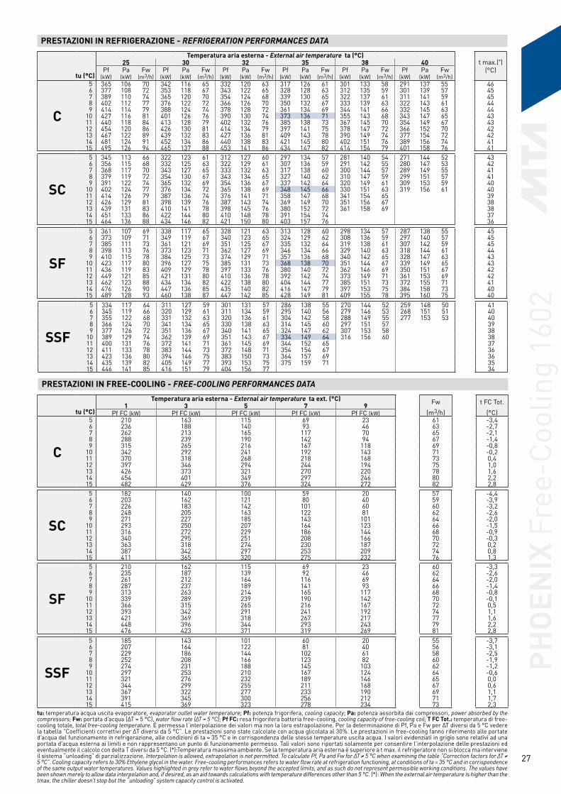
27
PRESTAZIONI IN REFRIGERAZIONE - REFRIGERATION PERFORMANCES DATA
tu (°C)
Temperatura aria esterna - External air temperature ta (°C)t max.(*)
(°C)25 30 32 35 38 40
Pf Pa Fw Pf Pa Fw Pf Pa Fw Pf Pa Fw Pf Pa Fw Pf Pa Fw(kW) (kW) (m3/h) (kW) (kW) (m3/h) (kW) (kW) (m3/h) (kW) (kW) (m3/h) (kW) (kW) (m3/h) (kW) (kW) (m3/h)
C
5 365 106 70 342 116 65 332 120 63 317 126 61 301 133 58 291 137 55 466 377 108 72 353 118 67 343 122 65 328 128 63 312 135 59 301 139 57 457 389 110 74 365 120 70 354 124 68 339 130 65 322 137 61 311 141 59 458 402 112 77 376 122 72 366 126 70 350 132 67 333 139 63 322 143 61 449 414 114 79 388 124 74 378 128 72 361 134 69 344 141 66 332 145 63 44
10 427 116 81 401 126 76 390 130 74 373 136 71 355 143 68 343 147 65 4311 440 118 84 413 128 79 402 132 76 385 138 73 367 145 70 354 149 67 4312 454 120 86 426 130 81 414 134 79 397 141 75 378 147 72 366 152 70 4213 467 122 89 439 132 83 427 136 81 409 143 78 390 149 74 377 154 72 4214 481 124 91 452 134 86 440 138 83 421 145 80 402 151 76 389 156 74 4115 495 126 94 465 137 88 453 141 86 434 147 82 414 154 79 401 158 76 41
SC
5 345 113 66 322 123 61 312 127 60 297 134 57 281 140 54 271 144 52 436 356 115 68 332 125 63 322 129 61 307 136 59 291 142 55 280 147 53 427 368 117 70 343 127 65 333 132 63 317 138 60 300 144 57 289 149 55 418 379 119 72 354 130 67 343 134 65 327 140 62 310 147 59 299 151 57 419 391 122 74 365 132 69 354 136 67 337 142 64 320 149 61 309 153 59 40
10 402 124 77 376 134 72 365 138 69 348 145 66 330 151 63 319 156 61 4011 414 126 79 387 136 74 376 141 71 358 147 68 341 154 65 3912 426 129 81 398 139 76 387 143 74 369 149 70 351 156 67 3813 439 131 83 410 141 78 398 145 76 380 152 72 361 158 69 3814 451 133 86 422 144 80 410 148 78 391 154 74 3715 464 136 88 434 146 82 421 150 80 403 157 76 36
SF
5 361 107 69 338 117 65 328 121 63 313 128 60 298 134 57 287 138 55 456 373 109 71 349 119 67 340 123 65 324 129 62 308 136 59 297 140 57 457 385 111 73 361 121 69 351 125 67 335 132 64 319 138 61 307 142 59 458 398 113 76 373 123 71 362 127 69 346 134 66 329 140 63 318 144 61 449 410 115 78 384 125 73 374 129 71 357 136 68 340 142 65 328 147 63 43
10 423 117 80 396 127 75 385 131 73 368 138 70 351 144 67 339 149 65 4311 436 119 83 409 129 78 397 133 76 380 140 72 362 146 69 350 151 67 4212 449 121 85 421 131 80 410 136 78 392 142 74 373 149 71 361 153 69 4213 462 123 88 434 134 82 422 138 80 404 144 77 385 151 73 372 155 71 4114 476 126 90 447 136 85 435 140 82 416 147 79 397 153 75 384 158 73 4015 489 128 93 460 138 87 447 142 85 428 149 81 409 155 78 395 160 75 40
SSF
5 334 117 64 311 127 59 301 131 57 286 138 55 270 144 52 259 148 50 416 345 119 66 320 129 61 311 134 59 295 140 56 279 146 53 268 151 51 407 355 122 68 331 132 63 320 136 61 304 142 58 288 149 55 277 153 53 408 366 124 70 341 134 65 330 138 63 314 145 60 297 151 57 399 377 126 72 351 136 67 340 141 65 324 147 62 307 153 58 38
10 389 129 74 362 139 69 351 143 67 334 149 64 316 156 60 3811 400 131 76 372 141 71 361 145 69 344 152 65 3712 411 133 78 383 144 73 372 148 71 354 154 67 3613 423 136 80 394 146 75 383 150 73 364 157 69 3614 435 139 82 405 149 77 393 153 75 375 159 71 3515 446 141 85 416 151 79 404 156 77 34
PRESTAZIONI IN FREE-COOLING - FREE-COOLING PERFORMANCES DATA
tu (°C)
Temperatura aria esterna - External air temperature ta ext. (°C) Fw
(m3/h)
t FC Tot.
(°C)1 3 5 7 9
Pf FC (kW) Pf FC (kW) Pf FC (kW) Pf FC (kW) Pf FC (kW)
C
5 210 163 115 69 23 61 -3,46 236 188 140 93 46 63 -2,77 262 213 165 117 70 65 -2,18 288 239 190 142 94 67 -1,49 315 265 216 167 118 69 -0,8
10 342 292 241 192 143 71 -0,211 370 318 268 218 168 73 0,412 397 346 294 244 194 75 1,013 426 373 321 270 220 78 1,614 454 401 349 297 246 80 2,215 482 429 376 324 272 82 2,8
tu: temperatura acqua uscita evaporatore, evaporator outlet water temperature; Pf: potenza frigorifera, cooling capacity; Pa: potenza assorbita dai compressori, power absorbed by the compressors; Fw: portata d’acqua (∆T = 5 °C), water flow rate (∆T = 5 °C); Pf FC: resa frigorifera batteria free-cooling, cooling capacity of free-cooling coil; T FC Tot.: temperatura di free-cooling totale, total free-cooling temperature. É permessa l’interpolazione dei valori ma non la loro estrapolazione. Per la determinazione di Pf, Pa e Fw per ∆T diversi da 5 °C vedere la tabella ”Coefficienti correttivi per ∆T diversi da 5 °C”. Le prestazioni sono state calcolate con acqua glicolata al 30%. Le prestazioni in free-cooling fanno riferimento alle portate d’acqua del funzionamento in refrigerazione, alle condizioni di ta = 35 °C e in corrispondenza delle stesse temperature uscita acqua. I valori evidenziati in grigio sono relativi ad una portata d'acqua esterna ai limiti e non rappresentano un punto di funzionamento permesso. Tali valori sono riportati solamente per consentire l'interpolazione delle prestazioni ed eventualmente il calcolo con delta T diversi da 5 °C. (*):Temperatura massima ambiente. Se la temperatura aria esterna è superiore a t max. il refrigeratore non si blocca ma interviene il sistema “unloading” di parzializzazione. Interpolation is allowed, extrapolation is not permitted. To calculate Pf, Pa and Fw for ∆T ≠ 5 °C when examining the table ”Correction factors for ∆T ≠ 5 °C”. Cooling capacity refers to 30% Ethylene glycol in the water. Free-cooling performances refers to water flow rate at refrigeration functioning, at conditions of ta = 35 °C and in corrispondence of the same output water temperatures. Values highlighted in grey refer to water flows beyond the accepted limits, and as such do not represent permissible working conditions. The values have been shown merely to allow data interpolation and, if desired, as an aid towards calculations with temperature differences other than 5 °C. (*): When the external air temperature is higher than the tmax. the chiller doesn’t stop but the “unloading” system capacity control is activated.
SC
5 182 140 100 59 20 57 -4,46 203 162 121 80 40 59 -3,97 226 183 142 101 60 60 -3,28 248 205 163 122 81 62 -2,69 271 227 185 143 101 64 -2,0
10 293 250 207 164 123 66 -1,511 316 272 229 186 144 68 -0,912 340 295 251 208 166 70 -0,313 363 318 274 230 187 72 0,214 387 342 297 253 209 74 0,815 411 365 320 275 232 76 1,3
SF
5 210 162 115 69 23 60 -3,36 235 187 139 92 46 62 -2,67 261 212 164 116 69 64 -2,08 287 237 189 141 93 66 -1,49 313 263 214 165 117 68 -0,8
10 339 289 239 190 142 70 -0,111 366 315 265 216 167 72 0,512 393 342 291 241 192 74 1,113 421 369 318 267 217 77 1,614 448 396 344 293 243 79 2,215 476 423 371 319 269 81 2,8
SSF
5 185 143 101 60 20 55 -3,76 207 164 122 81 40 56 -3,17 229 186 144 102 61 58 -2,58 252 208 166 123 82 60 -1,99 274 231 188 145 103 62 -1,2
10 297 253 210 167 124 64 -0,611 321 276 232 189 146 65 0,012 344 299 255 211 168 67 0,613 367 322 277 233 190 69 1,114 391 345 300 256 212 71 1,715 415 369 323 278 234 73 2,3
PHO
ENIX
Fre
e-Co
olin
g 16
02

28
DATI GENERALI - GENERAL DATA
C SCCircuiti frigoriferi Cooling circuits N° 2Compressori Compressors N° 2ESEER ESEER - 3,62 3,43Gradini di parzializzazione Capacity control % 0 - 25 - 50 - 62 - 75 - 87 - 100Alimentazione elettrica Electrical power supplyPotenza Power V/Ph/Hz 400 ± 10% / 3 - PE / 50Ausiliari Auxiliary V/Ph/Hz 24 - 230 ± 10% / 1 / 50 Batterie condensanti Condenser coilBatterie Coils N° 2 2Ranghi C1 C1 Rows N° 4 R x 1 4 R x 1Ranghi C2 C2 Rows N° 4 R x 1 4 R x 1Superficie frontale totale Total frontal surface m2 13,0 13,0Batterie free-cooling Free-cooling coilsBatterie Coils N° 2 2Ranghi Rows N° 4 R x 2 4 R x 2Superficie frontale totale Total frontal surface m2 13,0 13,0Ventilatori batterie condensanti Condenser coils fansVentilatori Fans N° 6 6Portata aria singola batteria Condenser coil airflow (each) m3/s 35,2 26,7Potenza (ciascuno) Power (each) kW 2,0 1,25Ventilatori batterie free-cooling Free-cooling coils fansVentilatori Fans N° 6 6Portata aria singola batteria Condenser coil airflow (each) m3/s 35,2 26,7Potenza (ciascuno) Power (each) kW 2,0 1,25Circuito idraulico Hydraulic circuitPortata min/max Min/max flow rate m3/h 34,8 / 100Volume d'acqua Water volume l 393Dimensioni e peso in esercizio Dimensions and installed weightLarghezza Width mm 2190 2190Profondità Length mm 6425 6425Altezza Height mm 2350 2350Peso Weight kg 5385 5680
FLI = potenza massima assorbita nelle condizioni limite di funzionamento; max power absorbed in the working limits condition; FLA = corrente massima assorbita nelle condizioni limite di funzionamento; max current absorbed in the working limits condition; ICF = corrente di spunto alla partenza dell’ultimo compressore nelle condizioni limite di funzionamento; start-up current at the start of the last compressor in the working limits condition. I valori massimi sono riferiti alle massime condizioni di funzionamento (comprendono il funzionamento dei ventilatori di condensazione, di free-cooling e i trasformatori ausiliari). The maximum values refer to the maximum working conditions (they comprehend the functionnement of condenser coils fans, the free-cooling fans and the auxiliary convertor).
ASSORBIMENTI ELETTRICI - ELECTRICAL DATA
FLI (kW) FLA (A) ICF (A)C 209 353 609
SC 200 333 589
Distanza (1)
KdBDistance (1)
L (m)1 153 105 6
10 0
Bande d'ottava Octave bands (Hz) PotenzaPower
PressionePressure63 125 250 500 1000 2000 4000 8000
Livello di potenza sonora Sound power level dB(A) dB (A) dB (A)10m
C 54,4 71,5 83,7 87,9 90,5 84,2 76,2 65,0 93,6 65,6SC 47,5 64,5 76,8 81,5 84,3 77,8 69,7 58,4 87,3 59,3
LIVELLI SONORI - SOUND LEVELS
Potenza sonora: determinata sulla base di misure effettuate in accordo alla normativa ISO 3744. Pressione sonora a 10 m: valore medio ricavato in campo libero su piano riflettente ad una distanza di 10 m dal lato batterie condensanti e a 1.6 m di altezza rispetto alla base di appoggio dell’unità. Valori con tolleranza ± 2 dB. I livelli sonori si riferiscono al funzionamento dell’unità a pieno carico in condizioni nominali. Il livello di pressione sonora si riferisce al funzionamento delle macchine con Free-cooling disinserito. (1) Per calcolare il livello di pressione sonora ad una distanza diversa impiegare la formula: dB(A)L=dB(A)10m+Kdb. Sound power: determined on the basis of measurements taken in accordance with the standard ISO 3744. Sound pressure at 10 m: average value obtained in free field on a reflective surface at a distance of 10 m from the side of the condenser coils and at a height of 1.6 m from the unit support base. Values with tolerance +/- 2 dB. The sound levels refer to operation of the unit under full load in nominal conditions. The sound pressure level is refered at functioning with Free-cooling Off. (1) To calculate a different distance of the sound pressure level, use the formula: dB(A)L=dB(A)10m+Kdb.PH
OEN
IX F
ree-
Cool
ing
1702

29
PRESTAZIONI IN REFRIGERAZIONE - REFRIGERATION PERFORMANCES DATA
tu (°C)
Temperatura aria esterna - External air temperature ta (°C)t max.(*)
(°C)25 30 32 35 38 40
Pf Pa Fw Pf Pa Fw Pf Pa Fw Pf Pa Fw Pf Pa Fw Pf Pa Fw(kW) (kW) (m3/h) (kW) (kW) (m3/h) (kW) (kW) (m3/h) (kW) (kW) (m3/h) (kW) (kW) (m3/h) (kW) (kW) (m3/h)
C
5 387 116 74 363 128 69 353 132 67 337 140 64 321 148 61 309 154 59 446 400 118 76 375 130 71 364 135 69 348 142 66 331 150 63 320 156 61 447 413 120 79 387 132 74 376 137 72 359 144 69 342 152 65 331 158 63 438 425 123 81 399 134 76 388 139 74 371 147 71 354 155 67 342 160 65 439 439 125 84 412 136 78 400 141 76 383 149 73 365 157 69 353 163 67 42
10 452 127 86 424 139 81 413 143 79 395 151 75 376 159 72 364 165 69 4211 466 129 89 437 141 83 425 146 81 407 154 77 388 162 74 375 168 71 4112 480 132 91 450 143 86 438 148 83 419 156 80 400 164 76 387 170 74 4013 494 134 94 463 146 88 451 151 86 432 159 82 412 167 78 399 173 76 4014 508 137 96 477 148 91 464 153 88 444 161 84 424 169 81 3915 522 139 99 491 151 93 477 156 91 457 164 87 437 172 83 39
SC
5 365 125 70 340 137 65 330 142 63 314 150 60 298 159 57 287 164 55 416 376 127 72 351 139 67 340 144 65 324 153 62 307 161 59 296 167 56 407 388 130 74 362 142 69 351 147 67 334 155 64 317 164 60 398 399 132 76 373 144 71 362 149 69 345 158 66 327 166 62 399 411 135 78 384 147 73 373 152 71 355 160 68 337 169 64 38
10 423 137 81 395 149 75 384 155 73 366 163 70 348 171 66 3811 436 140 83 407 152 77 395 157 75 377 166 72 3712 448 143 85 418 155 80 406 160 77 388 168 74 3613 460 145 87 430 158 82 418 163 79 399 171 76 3514 473 148 90 442 161 84 429 166 82 410 174 78 3515 486 151 92 454 163 86 441 169 84 34
PRESTAZIONI IN Free-cooling - Free-cooling PERFORMANCES DATA
tu (°C)
Temperatura aria esterna - External air temperature ta ext. (°C) Fw
(m3/h)
t FC Tot.
(°C)1 3 5 7 9
Pf FC (kW) Pf FC (kW) Pf FC (kW) Pf FC (kW) Pf FC (kW)
C
5 214 165 117 70 23 64 -4,06 240 191 142 94 47 66 -3,37 266 217 167 119 71 69 -2,78 293 243 193 144 95 71 -2,09 320 269 219 169 120 73 -1,4
10 347 296 245 195 145 75 -0,811 375 323 272 221 171 77 -0,212 403 350 298 247 196 80 0,413 431 378 326 274 223 82 1,014 460 406 353 301 249 84 1,615 488 434 381 328 276 87 2,1
tu: temperatura acqua uscita evaporatore, evaporator outlet water temperature; Pf: potenza frigorifera, cooling capacity; Pa: potenza assorbita dai compressori, power absorbed by the compressors; Fw: portata d’acqua (∆T = 5 °C), water flow rate (∆T = 5 °C); Pf FC: resa frigorifera batteria free-cooling, cooling capacity of free-cooling coil; T FC Tot.: temperatura di free-cooling totale, total free-cooling temperature.É permessa l’interpolazione dei valori ma non la loro estrapolazione. Per la determinazione di Pf, Pa e Fw per ∆T diversi da 5 °C vedere la tabella ”Coefficienti correttivi per ∆T diversi da 5 °C”. Le prestazioni sono state calcolate con acqua glicolata al 30%. Le prestazioni in free-cooling fanno riferimento alle portate d’acqua del funzionamento in refrigerazione, alle condizioni di ta = 35 °C e in corrispondenza delle stesse temperature uscita acqua. I valori evidenziati in grigio sono relativi ad una portata d'acqua esterna ai limiti e non rappresentano un punto di funzionamento permesso. Tali valori sono riportati solamente per consentire l'interpolazione delle prestazioni ed eventualmente il calcolo con delta T diversi da 5 °C. (*): Temperatura massima ambiente. Se la temperatura aria esterna è superiore a t max. il refrigeratore non si blocca ma interviene il sistema “unloading” di parzializzazione. Interpolation is allowed, extrapolation is not permitted. To calculate Pf, Pa and Fw for ∆T ≠ 5 °C when examining the table ”Correction factors for ∆T ≠ 5 °C”. Cooling capacity refers to 30% Ethylene glycol in the water. Free-cooling performances refers to water flow rate at refrigeration functioning, at conditions of ta = 35 °C and in corrispondence of the same output water temperatures. Values highlighted in grey refer to water flows beyond the accepted limits, and as such do not represent permissible working conditions. The values have been shown merely to allow data interpolation and, if desired, as an aid towards calculations with temperature differences other than 5 °C. (*): When the external air temperature is higher than the tmax. the chiller doesn’t stop but the “unloading” system capacity control is activated.
SC
5 184 142 101 60 20 60 -5,16 206 164 122 81 40 62 -4,47 228 186 143 102 61 64 -3,98 251 208 165 123 81 66 -3,39 273 230 187 144 103 68 -2,7
10 296 252 209 166 124 70 -2,111 320 275 231 188 145 72 -1,512 343 298 254 210 167 74 -1,013 366 321 277 232 189 76 -0,414 390 344 299 255 211 78 0,115 414 368 323 278 233 80 0,7
PHO
ENIX
Fre
e-Co
olin
g 17
02
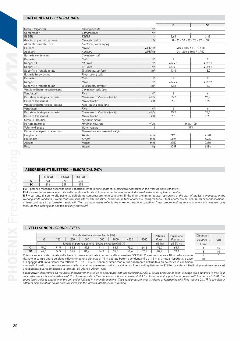
30
DATI GENERALI - GENERAL DATA
C SCCircuiti frigoriferi Cooling circuits N° 2Compressori Compressors N° 2ESEER ESEER - 3,65 3,45Gradini di parzializzazione Capacity control % 0 - 25 - 50 - 62 - 75 - 87 - 100Alimentazione elettrica Electrical power supplyPotenza Power V/Ph/Hz 400 ± 10% / 3 - PE / 50Ausiliari Auxiliary V/Ph/Hz 24 - 230 ± 10% / 1 / 50 Batterie condensanti Condenser coilBatterie Coils N° 2 2Ranghi C1 C1 Rows N° 4 R x 1 4 R x 1Ranghi C2 C2 Rows N° 4 R x 1 4 R x 1Superficie frontale totale Total frontal surface m2 13,0 13,0Batterie free-cooling Free-cooling coilsBatterie Coils N° 2 2Ranghi Rows N° 4 R x 2 4 R x 2Superficie frontale totale Total frontal surface m2 13,0 13,0Ventilatori batterie condensanti Condenser coils fansVentilatori Fans N° 6 6Portata aria singola batteria Condenser coil airflow (each) m3/s 35,2 26,7Potenza (ciascuno) Power (each) kW 2,0 1,25Ventilatori batterie free-cooling Free-cooling coils fansVentilatori Fans N° 6 6Portata aria singola batteria Condenser coil airflow (each) m3/s 35,2 26,7Potenza (ciascuno) Power (each) kW 2,0 1,25Circuito idraulico Hydraulic circuitPortata min/max Min/max flow rate m3/h 34,8 / 100Volume d'acqua Water volume l 393Dimensioni e peso in esercizio Dimensions and installed weightLarghezza Width mm 2190 2190Profondità Length mm 6425 6425Altezza Height mm 2350 2350Peso Weight kg 6089 6384
FLI = potenza massima assorbita nelle condizioni limite di funzionamento; max power absorbed in the working limits condition; FLA = corrente massima assorbita nelle condizioni limite di funzionamento; max current absorbed in the working limits condition; ICF = corrente di spunto alla partenza dell’ultimo compressore nelle condizioni limite di funzionamento; start-up current at the start of the last compressor in the working limits condition. I valori massimi sono riferiti alle massime condizioni di funzionamento (comprendono il funzionamento dei ventilatori di condensazione, di free-cooling e i trasformatori ausiliari). The maximum values refer to the maximum working conditions (they comprehend the functionnement of condenser coils fans, the free-cooling fans and the auxiliary convertor).
ASSORBIMENTI ELETTRICI - ELECTRICAL DATA
FLI (kW) FLA (A) ICF (A)C 223 379 635
SC 214 359 615
Distanza (1)
KdBDistance (1)
L (m)1 153 105 6
10 0
Bande d'ottava Octave bands (Hz) PotenzaPower
PressionePressure63 125 250 500 1000 2000 4000 8000
Livello di potenza sonora Sound power level dB(A) dB (A) dB (A)10m
C 54,7 71,5 83,1 87,8 91,1 83,1 75,2 64,2 93,7 65,7SC 47,9 64,5 76,2 81,4 84,9 76,5 68,6 57,6 87,4 59,4
LIVELLI SONORI - SOUND LEVELS
Potenza sonora: determinata sulla base di misure effettuate in accordo alla normativa ISO 3744. Pressione sonora a 10 m: valore medio ricavato in campo libero su piano riflettente ad una distanza di 10 m dal lato batterie condensanti e a 1.6 m di altezza rispetto alla base di appoggio dell’unità. Valori con tolleranza ± 2 dB. I livelli sonori si riferiscono al funzionamento dell’unità a pieno carico in condizioni nominali. Il livello di pressione sonora si riferisce al funzionamento delle macchine con Free-cooling disinserito. (1) Per calcolare il livello di pressione sonora ad una distanza diversa impiegare la formula: dB(A)L=dB(A)10m+Kdb. Sound power: determined on the basis of measurements taken in accordance with the standard ISO 3744. Sound pressure at 10 m: average value obtained in free field on a reflective surface at a distance of 10 m from the side of the condenser coils and at a height of 1.6 m from the unit support base. Values with tolerance +/- 2 dB. The sound levels refer to operation of the unit under full load in nominal conditions. The sound pressure level is refered at functioning with Free-cooling Off. (1) To calculate a different distance of the sound pressure level, use the formula: dB(A)L=dB(A)10m+Kdb.
PHO
ENIX
Fre
e-Co
olin
g 18
02

31
PRESTAZIONI IN REFRIGERAZIONE - REFRIGERATION PERFORMANCES DATA
tu (°C)
Temperatura aria esterna - External air temperature ta (°C)t max.(*)
(°C)25 30 32 35 38 40
Pf Pa Fw Pf Pa Fw Pf Pa Fw Pf Pa Fw Pf Pa Fw Pf Pa Fw(kW) (kW) (m3/h) (kW) (kW) (m3/h) (kW) (kW) (m3/h) (kW) (kW) (m3/h) (kW) (kW) (m3/h) (kW) (kW) (m3/h)
C
5 404 126 77 379 138 72 369 144 70 352 153 67 336 162 64 324 169 62 436 417 128 80 391 141 75 380 146 73 364 155 69 347 165 66 335 172 64 427 430 130 82 404 143 77 393 149 75 375 157 72 358 167 68 346 174 66 428 444 132 85 416 145 79 405 151 77 387 160 74 369 170 70 357 177 68 419 457 135 87 429 148 82 417 153 79 400 163 76 381 172 73 368 179 70 41
10 471 137 90 442 150 84 430 156 82 412 165 78 393 175 75 380 182 72 4011 485 140 92 455 153 87 443 159 84 424 168 81 405 178 77 3912 499 142 95 469 156 89 456 161 87 437 171 83 417 180 79 3913 514 145 98 482 158 92 469 164 89 449 173 85 429 183 82 3814 528 148 100 496 161 94 483 167 92 462 176 88 441 186 84 3815 543 151 103 510 164 97 496 170 94 475 179 90 37
SC
5 379 136 72 354 150 68 344 156 66 327 165 62 311 176 59 396 391 138 75 365 152 70 354 158 68 338 168 64 321 179 61 387 403 141 77 376 155 72 365 161 70 348 171 66 331 182 63 388 415 144 79 388 158 74 376 164 72 359 174 68 379 427 146 81 399 161 76 387 167 74 370 177 70 37
10 440 149 84 411 164 78 399 170 76 380 180 72 3611 452 152 86 422 167 80 410 173 78 391 183 74 3512 465 155 88 434 170 83 422 176 80 3413 477 158 91 446 173 85 433 179 82 3414 490 161 93 458 176 87 445 182 84 3315 503 165 96 471 179 89 457 186 87 32
PRESTAZIONI IN Free-cooling - Free-cooling PERFORMANCES DATA
tu (°C)
Temperatura aria esterna - External air temperature ta ext. (°C) Fw
(m3/h)
t FC Tot.
(°C)1 3 5 7 9
Pf FC (kW) Pf FC (kW) Pf FC (kW) Pf FC (kW) Pf FC (kW)
C
5 217 168 119 71 23 67 -4,46 243 193 144 95 47 69 -3,87 269 219 169 120 72 72 -3,18 296 245 195 145 96 74 -2,59 323 272 221 171 121 76 -1,9
10 351 299 247 197 147 78 -1,311 379 326 274 223 172 81 -0,712 407 354 301 249 198 83 -0,113 435 381 328 276 225 85 0,514 464 409 356 303 251 88 1,015 492 438 384 330 278 90 1,6
tu: temperatura acqua uscita evaporatore, evaporator outlet water temperature; Pf: potenza frigorifera, cooling capacity; Pa: potenza assorbita dai compressori, power absorbed by the compressors; Fw: portata d’acqua (∆T = 5 °C), water flow rate (∆T = 5 °C); Pf FC: resa frigorifera batteria free-cooling, cooling capacity of free-cooling coil; T FC Tot.: temperatura di free-cooling totale, total free-cooling temperature.É permessa l’interpolazione dei valori ma non la loro estrapolazione. Per la determinazione di Pf, Pa e Fw per ∆T diversi da 5 °C vedere la tabella ”Coefficienti correttivi per ∆T diversi da 5 °C”. Le prestazioni sono state calcolate con acqua glicolata al 30%. Le prestazioni in free-cooling fanno riferimento alle portate d’acqua del funzionamento in refrigerazione, alle condizioni di ta = 35 °C e in corrispondenza delle stesse temperature uscita acqua. I valori evidenziati in grigio sono relativi ad una portata d'acqua esterna ai limiti e non rappresentano un punto di funzionamento permesso. Tali valori sono riportati solamente per consentire l'interpolazione delle prestazioni ed eventualmente il calcolo con delta T diversi da 5 °C. (*):Temperatura massima ambiente. Se la temperatura aria esterna è superiore a t max. il refrigeratore non si blocca ma interviene il sistema “unloading” di parzializzazione. Interpolation is allowed, extrapolation is not permitted. To calculate Pf, Pa and Fw for ∆T ≠ 5 °C when examining the table ”Correction factors for ∆T ≠ 5 °C”. Cooling capacity refers to 30% Ethylene glycol in the water. Free-cooling performances refers to water flow rate at refrigeration functioning, at conditions of ta = 35 °C and in corrispondence of the same output water temperatures. Values highlighted in grey refer to water flows beyond the accepted limits, and as such do not represent permissible working conditions. The values have been shown merely to allow data interpolation and, if desired, as an aid towards calculations with temperature differences other than 5 °C. (*): When the external air temperature is higher than the tmax. the chiller doesn’t stop but the “unloading” system capacity control is activated.
SC
5 186 144 102 61 20 62 -5,56 208 166 123 82 41 64 -4,97 231 188 145 103 61 66 -4,38 253 210 167 124 82 68 -3,79 276 232 189 146 104 70 -3,2
10 299 255 211 168 125 72 -2,611 322 278 233 190 147 74 -2,012 346 301 256 212 168 76 -1,513 369 324 279 234 191 79 -0,914 393 347 302 257 213 81 -0,415 417 371 325 280 235 83 0,2
PHO
ENIX
Fre
e-Co
olin
g 18
02

32
DATI GENERALI - GENERAL DATA
C SCCircuiti frigoriferi Cooling circuits N° 2Compressori Compressors N° 2ESEER ESEER - 3,55 3,29Gradini di parzializzazione Capacity control % 0 - 25 - 50 - 62 - 75 - 87 - 100Alimentazione elettrica Electrical power supplyPotenza Power V/Ph/Hz 400 ± 10% / 3 - PE / 50Ausiliari Auxiliary V/Ph/Hz 24 - 230 ± 10% / 1 / 50 Batterie condensanti Condenser coilBatterie Coils N° 2 2Ranghi C1 C1 Rows N° 4 R x 1 4 R x 1Ranghi C2 C2 Rows N° 4 R x 1 4 R x 1Superficie frontale totale Total frontal surface m2 15,2 15,2Batterie free-cooling Free-cooling coilsBatterie Coils N° 2 2Ranghi Rows N° 4 R x 2 4 R x 2Superficie frontale totale Total frontal surface m2 15,2 15,2Ventilatori batterie condensanti Condenser coils fansVentilatori Fans N° 7 7Portata aria singola batteria Condenser coil airflow (each) m3/s 40,9 31,1Potenza (ciascuno) Power (each) kW 2,0 1,25Ventilatori batterie free-cooling Free-cooling coils fansVentilatori Fans N° 7 7Portata aria singola batteria Condenser coil airflow (each) m3/s 40,9 31,1Potenza (ciascuno) Power (each) kW 2,0 1,25Circuito idraulico Hydraulic circuitPortata min/max Min/max flow rate m3/h 37,7 / 101Volume d'acqua Water volume l 424Dimensioni e peso in esercizio Dimensions and installed weightLarghezza Width mm 2190 2190Profondità Length mm 7360 7360Altezza Height mm 2350 2350Peso Weight kg 6133 6503
FLI = potenza massima assorbita nelle condizioni limite di funzionamento; max power absorbed in the working limits condition; FLA = corrente massima assorbita nelle condizioni limite di funzionamento; max current absorbed in the working limits condition; ICF = corrente di spunto alla partenza dell’ultimo compressore nelle condizioni limite di funzionamento; start-up current at the start of the last compressor in the working limits condition. I valori massimi sono riferiti alle massime condizioni di funzionamento (comprendono il funzionamento dei ventilatori di condensazione, di free-cooling e i trasformatori ausiliari). The maximum values refer to the maximum working conditions (they comprehend the functionnement of condenser coils fans, the free-cooling fans and the auxiliary convertor).
ASSORBIMENTI ELETTRICI - ELECTRICAL DATA
FLI (kW) FLA (A) ICF (A)C 245 413 839
SC 234 389 815
Distanza (1)
KdBDistance (1)
L (m)1 153 105 6
10 0
Bande d'ottava Octave bands (Hz) PotenzaPower
PressionePressure63 125 250 500 1000 2000 4000 8000
Livello di potenza sonora Sound power level dB(A) dB (A) dB (A)10m
C 55,8 72,7 84,6 89,5 91,8 84,8 76,6 65,8 94,9 66,9SC 49,0 65,7 77,7 83,2 85,6 78,2 70,0 59,2 88,5 60,5
LIVELLI SONORI - SOUND LEVELS
Potenza sonora: determinata sulla base di misure effettuate in accordo alla normativa ISO 3744. Pressione sonora a 10 m: valore medio ricavato in campo libero su piano riflettente ad una distanza di 10 m dal lato batterie condensanti e a 1.6 m di altezza rispetto alla base di appoggio dell’unità. Valori con tolleranza ± 2 dB. I livelli sonori si riferiscono al funzionamento dell’unità a pieno carico in condizioni nominali. Il livello di pressione sonora si riferisce al funzionamento delle macchine con Free-cooling disinserito. (1) Per calcolare il livello di pressione sonora ad una distanza diversa impiegare la formula: dB(A)L=dB(A)10m+Kdb. Sound power: determined on the basis of measurements taken in accordance with the standard ISO 3744. Sound pressure at 10 m: average value obtained in free field on a reflective surface at a distance of 10 m from the side of the condenser coils and at a height of 1.6 m from the unit support base. Values with tolerance +/- 2 dB. The sound levels refer to operation of the unit under full load in nominal conditions. The sound pressure level is refered at functioning with Free-cooling Off. (1) To calculate a different distance of the sound pressure level, use the formula: dB(A)L=dB(A)10m+Kdb.PH
OEN
IX F
ree-
Cool
ing
2002

33
PRESTAZIONI IN REFRIGERAZIONE - REFRIGERATION PERFORMANCES DATA
tu (°C)
Temperatura aria esterna - External air temperature ta (°C)t max.(*)
(°C)25 30 32 35 38 40
Pf Pa Fw Pf Pa Fw Pf Pa Fw Pf Pa Fw Pf Pa Fw Pf Pa Fw(kW) (kW) (m3/h) (kW) (kW) (m3/h) (kW) (kW) (m3/h) (kW) (kW) (m3/h) (kW) (kW) (m3/h) (kW) (kW) (m3/h)
C
5 459 135 88 430 148 82 417 153 80 398 162 76 378 172 72 365 179 70 446 474 137 90 444 150 85 431 156 82 411 165 78 391 174 75 377 181 72 437 490 140 93 458 153 87 445 158 85 425 167 81 404 177 77 390 184 74 438 505 142 96 473 155 90 459 161 88 439 170 84 418 180 80 403 187 77 429 521 145 99 488 158 93 474 164 90 453 173 86 431 183 82 417 190 79 42
10 537 147 102 503 161 96 489 166 93 467 176 89 445 186 85 430 193 82 4111 553 150 105 518 163 99 504 169 96 482 179 92 459 189 87 444 196 84 4112 569 153 108 534 166 101 519 172 99 497 182 94 473 192 90 457 199 87 4013 586 156 111 550 169 104 535 175 102 512 185 97 488 195 93 472 202 90 4014 603 159 115 566 173 107 551 178 105 527 188 100 503 198 95 3915 621 162 118 583 176 111 567 182 108 542 191 103 518 202 98 38
SC
5 431 145 82 402 159 77 389 165 74 370 174 71 350 185 67 337 192 64 406 445 148 85 415 161 79 402 167 77 382 177 73 362 188 69 348 195 66 407 459 150 88 428 164 82 414 170 79 395 180 75 374 191 71 398 473 153 90 441 167 84 428 173 81 407 183 78 386 194 73 399 487 156 93 454 170 86 440 177 84 420 187 80 398 197 76 38
10 502 159 95 468 174 89 454 180 86 432 190 82 3711 516 162 98 482 177 92 467 183 89 445 193 85 3612 531 166 101 496 180 94 481 187 91 458 197 87 3613 546 169 104 510 184 97 495 190 94 472 200 90 3514 561 172 107 524 187 99 509 194 97 3415 577 176 109 538 191 102 523 198 99 33
PRESTAZIONI IN Free-cooling - Free-cooling PERFORMANCES DATA
tu (°C)
Temperatura aria esterna - External air temperature ta ext. (°C) Fw
(m3/h)
t FC Tot.
(°C)1 3 5 7 9
Pf FC (kW) Pf FC (kW) Pf FC (kW) Pf FC (kW) Pf FC (kW)
C
5 257 199 141 84 28 76 -3,76 289 229 171 113 56 78 -3,17 320 260 201 143 85 81 -2,48 352 292 232 173 114 84 -1,89 384 323 263 203 144 86 -1,2
10 417 355 294 234 174 89 -0,611 450 388 326 265 205 92 0,012 483 420 358 296 236 94 0,613 517 453 390 328 267 97 1,214 551 487 423 360 298 100 1,715 585 520 456 393 330 103 2,3
tu: temperatura acqua uscita evaporatore, evaporator outlet water temperature; Pf: potenza frigorifera, cooling capacity; Pa: potenza assorbita dai compressori, power absorbed by the compressors; Fw: portata d’acqua (∆T = 5 °C), water flow rate (∆T = 5 °C); Pf FC: resa frigorifera batteria free-cooling, cooling capacity of free-cooling coil; T FC Tot.: temperatura di free-cooling totale, total free-cooling temperature.É permessa l’interpolazione dei valori ma non la loro estrapolazione. Per la determinazione di Pf, Pa e Fw per ∆T diversi da 5 °C vedere la tabella ”Coefficienti correttivi per ∆T diversi da 5 °C”. Le prestazioni sono state calcolate con acqua glicolata al 30%. Le prestazioni in free-cooling fanno riferimento alle portate d’acqua del funzionamento in refrigerazione, alle condizioni di ta = 35 °C e in corrispondenza delle stesse temperature uscita acqua. I valori evidenziati in grigio sono relativi ad una portata d'acqua esterna ai limiti e non rappresentano un punto di funzionamento permesso. Tali valori sono riportati solamente per consentire l'interpolazione delle prestazioni ed eventualmente il calcolo con delta T diversi da 5 °C. (*):Temperatura massima ambiente. Se la temperatura aria esterna è superiore a t max. il refrigeratore non si blocca ma interviene il sistema “unloading” di parzializzazione. Interpolation is allowed, extrapolation is not permitted. To calculate Pf, Pa and Fw for ∆T ≠ 5 °C when examining the table ”Correction factors for ∆T ≠ 5 °C”. Cooling capacity refers to 30% Ethylene glycol in the water. Free-cooling performances refers to water flow rate at refrigeration functioning, at conditions of ta = 35 °C and in corrispondence of the same output water temperatures. Values highlighted in grey refer to water flows beyond the accepted limits, and as such do not represent permissible working conditions. The values have been shown merely to allow data interpolation and, if desired, as an aid towards calculations with temperature differences other than 5 °C. (*): When the external air temperature is higher than the tmax. the chiller doesn’t stop but the “unloading” system capacity control is activated.
SC
5 221 171 121 72 24 71 -4,86 247 196 146 97 48 73 -4,27 274 223 172 122 73 75 -3,68 301 249 198 147 98 78 -3,09 328 276 224 173 123 80 -2,4
10 355 302 250 199 148 82 -1,911 383 329 277 225 174 85 -1,312 410 357 304 252 200 87 -0,813 438 384 331 278 226 90 -0,214 467 412 358 305 253 92 0,315 495 440 386 332 279 95 0,9
PHO
ENIX
Fre
e-Co
olin
g 20
02

34
DATI GENERALI - GENERAL DATA
C SCCircuiti frigoriferi Cooling circuits N° 2Compressori Compressors N° 2ESEER ESEER - 3,42 3,13Gradini di parzializzazione Capacity control % 0 - 25 - 50 - 62 - 75 - 87 - 100Alimentazione elettrica Electrical power supplyPotenza Power V/Ph/Hz 400 ± 10% / 3 - PE / 50Ausiliari Auxiliary V/Ph/Hz 24 - 230 ± 10% / 1 / 50 Batterie condensanti Condenser coilBatterie Coils N° 2 2Ranghi C1 C1 Rows N° 4 R x 1 4 R x 1Ranghi C2 C2 Rows N° 4 R x 1 4 R x 1Superficie frontale totale Total frontal surface m2 15,2 15,2Batterie free-cooling Free-cooling coilsBatterie Coils N° 2 2Ranghi Rows N° 4 R x 2 4 R x 2Superficie frontale totale Total frontal surface m2 15,2 15,2Ventilatori batterie condensanti Condenser coils fansVentilatori Fans N° 7 7Portata aria singola batteria Condenser coil airflow (each) m3/s 40,9 31,1Potenza (ciascuno) Power (each) kW 2,0 1,25Ventilatori batterie free-cooling Free-cooling coils fansVentilatori Fans N° 7 7Portata aria singola batteria Condenser coil airflow (each) m3/s 40,9 31,1Potenza (ciascuno) Power (each) kW 2,0 1,25Circuito idraulico Hydraulic circuitPortata min/max Min/max flow rate m3/h 37,7 / 107Volume d'acqua Water volume l 424Dimensioni e peso in esercizio Dimensions and installed weightLarghezza Width mm 2190 2190Profondità Length mm 7360 7360Altezza Height mm 2350 2350Peso Weight kg 6154 6524
FLI = potenza massima assorbita nelle condizioni limite di funzionamento; max power absorbed in the working limits condition; FLA = corrente massima assorbita nelle condizioni limite di funzionamento; max current absorbed in the working limits condition; ICF = corrente di spunto alla partenza dell’ultimo compressore nelle condizioni limite di funzionamento; start-up current at the start of the last compressor in the working limits condition. I valori massimi sono riferiti alle massime condizioni di funzionamento (comprendono il funzionamento dei ventilatori di condensazione, di free-cooling e i trasformatori ausiliari). The maximum values refer to the maximum working conditions (they comprehend the functionnement of condenser coils fans, the free-cooling fans and the auxiliary convertor).
ASSORBIMENTI ELETTRICI - ELECTRICAL DATA
FLI (kW) FLA (A) ICF (A)C 261 437 863
SC 251 414 840
Distanza (1)
KdBDistance (1)
L (m)1 153 105 6
10 0
Bande d'ottava Octave bands (Hz) PotenzaPower
PressionePressure63 125 250 500 1000 2000 4000 8000
Livello di potenza sonora Sound power level dB(A) dB (A) dB (A)10m
C 55,1 72,7 84,3 89,8 91,9 84,4 76,0 65,1 94,9 66,9SC 48,1 65,7 77,3 83,5 85,7 77,8 69,3 58,4 88,6 60,6
LIVELLI SONORI - SOUND LEVELS
Potenza sonora: determinata sulla base di misure effettuate in accordo alla normativa ISO 3744. Pressione sonora a 10 m: valore medio ricavato in campo libero su piano riflettente ad una distanza di 10 m dal lato batterie condensanti e a 1.6 m di altezza rispetto alla base di appoggio dell’unità. Valori con tolleranza ± 2 dB. I livelli sonori si riferiscono al funzionamento dell’unità a pieno carico in condizioni nominali. Il livello di pressione sonora si riferisce al funzionamento delle macchine con Free-cooling disinserito. (1) Per calcolare il livello di pressione sonora ad una distanza diversa impiegare la formula: dB(A)L=dB(A)10m+Kdb. Sound power: determined on the basis of measurements taken in accordance with the standard ISO 3744. Sound pressure at 10 m: average value obtained in free field on a reflective surface at a distance of 10 m from the side of the condenser coils and at a height of 1.6 m from the unit support base. Values with tolerance +/- 2 dB. The sound levels refer to operation of the unit under full load in nominal conditions. The sound pressure level is refered at functioning with Free-cooling Off. (1) To calculate a different distance of the sound pressure level, use the formula: dB(A)L=dB(A)10m+Kdb.
PHO
ENIX
Fre
e-Co
olin
g 22
02

35
PRESTAZIONI IN REFRIGERAZIONE - REFRIGERATION PERFORMANCES DATA
tu (°C)
Temperatura aria esterna - External air temperature ta (°C)t max.(*)
(°C)25 30 32 35 38 40
Pf Pa Fw Pf Pa Fw Pf Pa Fw Pf Pa Fw Pf Pa Fw Pf Pa Fw(kW) (kW) (m3/h) (kW) (kW) (m3/h) (kW) (kW) (m3/h) (kW) (kW) (m3/h) (kW) (kW) (m3/h) (kW) (kW) (m3/h)
C
5 489 150 93 455 164 87 442 170 84 420 179 80 397 189 76 382 196 73 436 505 153 96 471 166 90 456 172 87 434 182 83 411 192 78 395 200 75 427 522 156 99 486 169 93 471 175 90 449 185 86 425 195 81 409 203 78 418 538 159 103 502 172 96 487 178 93 463 188 88 439 199 84 423 206 81 419 555 162 106 518 175 99 502 182 96 478 191 91 454 202 86 437 210 83 40
10 572 165 109 534 179 102 518 185 99 494 195 94 469 206 89 3911 590 168 112 550 182 105 534 188 102 509 198 97 483 209 92 3912 607 171 115 567 185 108 551 192 105 525 202 100 499 213 95 3813 625 174 119 584 189 111 567 195 108 541 206 103 3714 643 178 122 601 193 114 584 199 111 557 209 106 3715 662 182 126 619 197 117 601 203 114 574 214 109 36
SC
5 455 162 87 421 176 80 407 183 78 385 193 74 363 204 69 396 469 165 90 435 179 83 420 186 80 398 196 76 375 207 72 387 484 168 92 448 183 85 433 189 83 411 200 78 378 499 171 95 462 186 88 447 193 85 424 203 81 379 514 175 98 476 190 91 461 197 88 437 207 83 36
10 529 178 101 491 194 93 475 200 90 450 211 86 3511 544 182 103 505 198 96 489 204 93 3412 559 186 106 520 202 99 503 209 96 3313 575 190 109 535 206 102 518 213 98 3214 591 194 112 549 210 104 532 217 101 3215 607 198 115 564 215 107 31
PRESTAZIONI IN Free-cooling - Free-cooling PERFORMANCES DATA
tu (°C)
Temperatura aria esterna - External air temperature ta ext. (°C) Fw
(m3/h)
t FC Tot.
(°C)1 3 5 7 9
Pf FC (kW) Pf FC (kW) Pf FC (kW) Pf FC (kW) Pf FC (kW)
C
5 261 202 143 85 28 80 -4,26 292 233 173 115 57 83 -3,67 324 264 204 145 86 86 -3,08 357 295 235 175 116 88 -2,49 389 327 266 206 146 91 -1,8
10 422 360 298 237 176 94 -1,311 455 392 330 268 207 97 -0,712 489 425 362 300 238 100 -0,113 523 459 395 332 270 103 0,414 557 492 428 364 302 106 1,015 592 526 461 397 334 109 1,6
tu: temperatura acqua uscita evaporatore, evaporator outlet water temperature; Pf: potenza frigorifera, cooling capacity; Pa: potenza assorbita dai compressori, power absorbed by the compressors; Fw: portata d’acqua (∆T = 5 °C), water flow rate (∆T = 5 °C); Pf FC: resa frigorifera batteria free-cooling, cooling capacity of free-cooling coil; T FC Tot.: temperatura di free-cooling totale, total free-cooling temperature.É permessa l’interpolazione dei valori ma non la loro estrapolazione. Per la determinazione di Pf, Pa e Fw per ∆T diversi da 5 °C vedere la tabella ”Coefficienti correttivi per ∆T diversi da 5 °C”. Le prestazioni sono state calcolate con acqua glicolata al 30%. Le prestazioni in free-cooling fanno riferimento alle portate d’acqua del funzionamento in refrigerazione, alle condizioni di ta = 35 °C e in corrispondenza delle stesse temperature uscita acqua. I valori evidenziati in grigio sono relativi ad una portata d'acqua esterna ai limiti e non rappresentano un punto di funzionamento permesso. Tali valori sono riportati solamente per consentire l'interpolazione delle prestazioni ed eventualmente il calcolo con delta T diversi da 5 °C. (*):Temperatura massima ambiente. Se la temperatura aria esterna è superiore a t max. il refrigeratore non si blocca ma interviene il sistema “unloading” di parzializzazione. Interpolation is allowed, extrapolation is not permitted. To calculate Pf, Pa and Fw for ∆T ≠ 5 °C when examining the table ”Correction factors for ∆T ≠ 5 °C”. Cooling capacity refers to 30% Ethylene glycol in the water. Free-cooling performances refers to water flow rate at refrigeration functioning, at conditions of ta = 35 °C and in corrispondence of the same output water temperatures. Values highlighted in grey refer to water flows beyond the accepted limits, and as such do not represent permissible working conditions. The values have been shown merely to allow data interpolation and, if desired, as an aid towards calculations with temperature differences other than 5 °C. (*): When the external air temperature is higher than the tmax. the chiller doesn’t stop but the “unloading” system capacity control is activated.
SC
5 223 172 122 73 24 74 -5,36 249 198 148 98 49 76 -4,77 276 224 173 123 73 78 -4,18 303 251 199 148 98 81 -3,69 330 277 226 174 124 83 -3,0
10 357 304 252 200 149 86 -2,411 385 332 279 227 175 88 -1,912 413 359 306 253 201 91 -1,413 441 387 333 280 228 93 -0,814 469 415 360 307 254 96 -0,315 498 443 388 334 281 99 0,2
PHO
ENIX
Fre
e-Co
olin
g 22
02
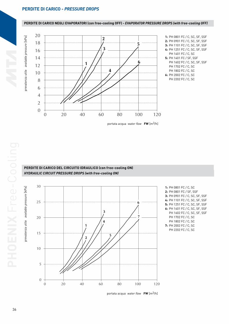
PHO
ENIX
Fre
e-Co
olin
g
36
PERDITE DI CARICO - PRESSURE DROPS
PERDITE DI CARICO NEGLI EVAPORATORI (con free-cooling OFF) - EVAPORATOR PRESSURE DROPS (with free-cooling OFF)
0
2
4
6
8
10
12
14
16
18
20
0 20 40 60 80 100 120
1
2
3
4
5
6
portata acqua water flow FW [m3/h]
prev
alen
za u
tile
ava
ilabl
e pr
essu
re [k
Pa]
prev
alen
za u
tile
ava
ilabl
e pr
essu
re [k
Pa]
portata acqua water flow FW [m3/h]
PERDITE DI CARICO DEL CIRCUITO IDRAULICO (con free-cooling ON) HYDRAULIC CIRCUIT PRESSURE DROPS (with free-cooling ON)
0
5
10
15
20
25
30
0 20 40 60 80 100 120
1
2
3
4
5
6
7
1: PH 0801 FC / C, SC, SF, SSF2: PH 0901 FC / C, SC, SF, SSF3: PH 1101 FC / C, SC, SF, SSF4: PH 1251 FC / C, SC, SF, SSF PH 1401 FC / C, SC5: PH 1401 FC / SF, SSF PH 1602 FC / C, SC, SF, SSF PH 1702 FC / C, SC PH 1802 FC / C, SC6: PH 2002 FC / C, SC PH 2202 FC / C, SC
1: PH 0801 FC / C, SC2: PH 0801 FC / SF, SSF3: PH 0901 FC / C, SC, SF, SSF4: PH 1101 FC / C, SC, SF, SSF5: PH 1251 FC / C, SC, SF, SSF 6: PH 1401 FC / C, SC, SF, SSF PH 1602 FC / C, SC, SF, SSF PH 1702 FC / C, SC PH 1802 FC / C, SC7: PH 2002 FC / C, SC PH 2202 FC / C, SC

PHO
ENIX
Fre
e-Co
olin
g
37
FATTORI DI SPORCAMENTO - FOULING FACTORS
Fattore sporcamento evaporatore (m2°C/W)Evaporator fouling factor (m2°C/W)
5x10⁻⁵ 1x10⁻⁴ 4x10⁻⁴
Fattore correttivo potenza frigorifera - Cooling capacity correction factor k2 0,99 0,99 0,99
Fattore correttivo potenza assorbita - Absorbed power correction factor Kp2 0,98 0,99 0,98
Per valutare l’effetto dello sporcamento dell’evaporatore, del desurriscaldatore e del recuperatore, moltiplicare la resa frigorifera Pf per kf2 e la potenza assorbita Pa per kp2. To determine the effect of fouling on the evaporator, or to the desuperheater and heat recovery, multiply the cooling capacity Pf by kf2 and the absorbed power Pa by kp2. (Pf* = Pf x kf2, Pa* = Pa x kp2).
% Glicole etilenico in peso % Ethylene glycol by weight
0 10 20 30 40 50
Fattore correttivo potenza frigorifera - Cooling capacity correction factor Kf1 1,04 1,03 1,02 1,00 0,981 0,960
Fattore correttivo potenza assorbita - Absorbed power correction factor Kp1 1,02 1,01 1,01 1,00 0,991 0,981
Coefficiente correttivo portata acqua - Water flow correction factor (1) KFWE1 0,941 0,961 0,980 1,00 1,02 1,04
Fattore correttivo perdite di carico - Pressure drop correction factor FC OFF Kdp1 0,787 0,854 0,925 1,00 1,08 1,16
Fattore correttivo perdite di carico - Pressure drop correction factor FC ON Kdp1 0,747 0,826 0,910 1,00 1,10 1,20
SOLUZIONI DI ACQUA E GLICOLE ETILENICO - SOLUTIONS OF WATER AND ETHYLENE GLYCOL
Moltiplicare le prestazioni della macchina per i coefficienti correttivi riportati in tabella. (Pf* = Pf x Kf1). Multiply the unit performance by the correction factors given in the table (Pf* = Pf x Kf1). (1) KFWE1 = coefficiente correttivo (riferito alla potenza frigorifera corretta con Kf) per ottenere la portata d’acqua con un salto termico di 5 °C. (1) KFWE1 = correction factor (refers to the cooling capacity corrected by Kf) to obtain the water flow with a ∆T of 5 °C. FC OFF = Free-cooling OFF; FC ON = Free-cooling ON.
Altitudine Altitude0 500 1000 1500 2000 2500
Fattore correttivo potenza frigorifera - Cooling capacity correction factor k4 1 0,99 0,98 0,977 0,972 0,960
Fattore correttivo potenza assorbita - Absorbed power correction factor Kp4 1 1,01 1,01 1,02 1,03 1,03
Riduzione max / min temp. aria esterna - Reduction of the max. / min. external air temp. (*) Kt3(°C) 0 0,6 1,1 1,8 2,5 3,3
COEFFICIENTI CORRETTIVI CONDENSATORI - CONDENSER CORRECTION FACTORS
Moltiplicare le prestazioni della macchina per i coefficienti correttivi riportati in tabella (Pf* = Pf x Kf3, Pa* = Pa x Kp3). Multiply the unit performance by the correction factors given in the table (Pf* = Pf x Kf3, Pa* = Pa x Kp3). (*) Per ottenere la max temperatura aria esterna sottrarre i valori indicati dai valori di max temperatura aria esterna della tabella prestazioni (Ta* = Ta-Kt3). (*) To obtain the maximum external air temperature, subtract the values indicated from the maximum external air temperature in the performance table (Ta* = Ta-Kt3).
COEFFICIENTI CORRETTIVI ∆T ≠ 5 °C - CORRECTION FACTORS ∆T ≠ 5 °C
∆T3 4 5 6 7 8
Fattore correttivo potenza frigorifera - Cooling capacity correction factor k4 0,997 0,998 1 1,00 1,01 1,01
Fattore correttivo potenza assorbita - Absorbed power correction factor Kp4 0,999 0,999 1 1,00 1,00 1,00
I dati sono riferiti alle seguenti condizioni: acqua glicolata al 30%; temperatura aria esterna 35 °C; fattore sporcamento evaporatore (m2 °C/W) = 0,000043; altitudine = 0 m. Moltiplicare le prestazioni della macchina per i coefficienti correttivi riportati in tabella (Pf* = Pf x Kf4, Pa* = Pa x Kp4). La nuova portata d’acqua attraverso l’evaporatore si calcola per mezzo della seguente relazione Fw (l/h) = Pf* (kW) x 860 / ∆T dove ∆T è la differenza di temperatura attraverso l’evaporatore (°C).Data in the table refers at the following conditions: 30% Ethylene glycol in the water; external air temperature 35 °C; evaporator fouling factor (m2 °C/W) = 0,000043; altitude = 0 m. Multiply the unit performance by the correction factors given in table (Pf* = Pf x Kf4, Pa* = Pa x Kp4). The new water flow to the evaporator is calculated with the following equation: Fw (l/h) = Pf* (kW) x 860 / ∆T where ∆T is the delta T of the water through the evaporator (°C).
LIMITI DI FUNZIONAMENTO E COEFFICIENTI CORRETTIVI WORKING LIMITS AND CORRECTION FACTORS
LIMITI DI FUNZIONAMENTO - WORKING LIMITS
(1) Macchine provviste di regolatore elettronico (fornito come standard nelle versioni a bassa temperatura aria esterna, fino a -15 °C) della velocità di rotazione dei ventilatori. Units fournited with electronic fans speed control (standard in the versions low external air temperature, up to -15 °C).
(2) Vedi tabella prestazioni delle macchine. See the unit performance data.(3) Macchine nelle versioni bassa temperatura aria esterna, fino a -15 °C. Units in the versions low external air temperature, up to -15 °C.(4) Compatibile con le FW min/max dell'evaporatore. Compatibly with the min/max FW of the evaporator.
PHOENIX Free-CoolingMin Max
C / SC SF / SSF C / SC SF / SSFTemperatura aria esterna macchina standard - External air temperature standard machine °C -10 5 (2) (2)
Temperatura aria esterna macchina con r.e. - External air temperature machine with e.r. (1) °C -10 -10 (2) (2)
Temperatura aria esterna macchina con b.t.a. - External air temperature machine with l.a.t. (3) °C -15 -15 (2) (2)
Temperatura ingresso acqua evaporatore - Evaporator inlet water temperature (4) °C 8 8 30 30
Temperatura uscita acqua evaporatore - Evaporator outlet water temperature (4) °C 5 5 25 25
Salto termico dell’acqua - Delta T of the water °C 3 3 8 8
Pressione circuiti idraulici - Pressure in hydraulic circuits bar g 0 0 6 6
PHO
ENIX
Fre
e-Co
olin
g
38
DISEGNI DI INGOMBRO - OVERALL DIMENSIONS
PH 0801 FC/C SC
1350
min
.13
50 m
in.
1500 min.
735
750
18750 mm2
P1
P4 P3
P2
N° 2 Ø 12 *110110
65-9
0
2108110 40
345
N° 2 + 2 Ø 30 *
***
2190
70
3550125
**
335
*
155 2615 155
590
255
2060
2925
275
360
660
2350
Ø OUT Ø IN
PH 0801 FCC SC
Attacchi acqua evaporatore Ø OUT, Ø IN DN 100Evaporator water connections
: Alimentazione elettrica - Electrical power supply
: Ingresso acqua - Water inlet
: Uscita acqua - Water outlet
: Supporti antivribanti (opzionale) - Vibration damping supports (optional) * : Filtri (opzionale) - Filters (optional) **
P1 P2 P3 P4PH 0801 FC / C SC Kg 698 662 636 670
Distribuzione del peso sugli appoggi - Mounting weights
: Cofano compressori (opzionale) - Hausing compressors (optional) ***

PHO
ENIX
Fre
e-Co
olin
g
39
PH 0801 FC/SF SSF - PH 0901 FC/C SC - PH 1101 FC/C SC
N° 2 Ø 12 *110110
65-9
0
1800
min
.18
00 m
in.
1500 min.
735
750
18750 mm2
P1
P4 P3
P2
2108 0404
N° 2 + 2 Ø 30 *
G
***
2190
F
Ø OUT Ø IN
**
*
640
DC
2615
3895
E
640
205
B
360
2350
125 4465
A
: Alimentazione elettrica - Electrical power supply
: Ingresso acqua - Water inlet
: Uscita acqua - Water outlet
: Supporti antivribanti (opzionale) - Vibration damping supports (optional) * : Filtri (opzionale) - Filters (optional) **: Cofano compressori (opzionale) - Hausing compressors (optional) ***
PH 0801 FC PH 0901 FC PH 1101 FCSF SSF C SC C SC
A mm 335 335 385 385 385 385B mm 660 660 410 410 410 410C mm 760 760 805 805 805 805D mm 2060 2060 2785 2785 2785 2785E mm 1075 1075 305 305 305 305F mm 70 70 70 70 70 70G mm 345 345 375 375 375 375
Attacchi acqua evaporatore Ø OUT, Ø IN DN 100 DN 125 DN 125Evaporator water connections
P1 P2 P3 P4PH 0801 FC / SF SSF Kg 791 744 686 759PH 0901 FC / C SC Kg 858 780 749 824PH 1101 FC / C SC Kg 982 911 875 944
Distribuzione del peso sugli appoggi - Mounting weights

PHO
ENIX
Fre
e-Co
olin
g
40
PH 0901 FC/SF SSF - PH 1251 FC/C SC
2250
min
.22
50 m
in.
18750 mm2
P5P6P7P8
P1 3P2P P4
N° 2 Ø 12 *110110
65-9
0
F
Ø INØ OUT
155133518151335110
A
EDC
5025974063
801204 40
G
***
2350
5365125
N° 4 + 4 Ø 30 *
**
*
B
1500 min.
735
750
: Alimentazione elettrica - Electrical power supply
: Ingresso acqua - Water inlet
: Uscita acqua - Water outlet
: Supporti antivribanti (opzionale) - Vibration damping supports (optional) * : Filtri (opzionale) - Filters (optional) **: Cofano compressori (opzionale) - Hausing compressors (optional) ***
PH 0801 FC PH 0901 FCSF SSF C SC
A mm 385 385 385 385B mm 410 410 405 405C mm 1255 1255 1255 1255D mm 2785 2785 3240 3240E mm 755 755 300 300F mm 70 70 70 70G mm 375 375 375 375
Attacchi acqua evaporatore Ø OUT, Ø IN DN 125 DN 125Evaporator water connections
P1 P2 P3 P4 P5 P6 P7 P8PH 0901 FC / SF SSF Kg 643 549 299 429 460 366 366 496PH 1251 FC / C SC Kg 889 779 378 498 572 452 452 562
Distribuzione del peso sugli appoggi - Mounting weights

PHO
ENIX
Fre
e-Co
olin
g
41
PH 1101 FC/SF SSF - PH 1401 FC/C SC - PH 1602 FC/C SC
PH 1702 FC/C SC - PH 1802 FC/C SC
2190
4040 2108
N° 4 + 4 Ø 30 *
G
2250
min
.22
50 m
in.
1500 min.
750
735 P7P8 P5P6
P1 P2 P3 P4
18750 mm2
360 5730
53315181
D E
155
205
B
2350
6300125
A
*
**
***
C
1090 1335
Ø OUT Ø IN
F
N° 2 Ø 12 *
110110
65-9
0
: Alimentazione elettrica - Electrical power supply
: Ingresso acqua - Water inlet
: Uscita acqua - Water outlet
: Supporti antivribanti (opzionale) - Vibration damping supports (optional) * : Filtri (opzionale) - Filters (optional) **: Cofano compressori (opzionale) - Hausing compressors (optional) ***
PH 1101 FC PH 1401 FC PH 1602 FC PH 1702 FC PH 1802 FCSF SSF C SC C SC C SC C SC
A mm 385 385 410 410 410 410 410 410 410 410B mm 410 410 410 410 410 410 410 410 410 410C mm 2195 2195 2145 2145 2145 2145 2145 2145 2145 2145D mm 2780 2780 3285 3285 3285 3285 3285 3285 3285 3285E mm 755 755 300 300 300 300 300 300 300 300F mm 70 70 5 5 5 5 5 5 5 5G mm 375 375 400 400 400 400 400 400 400 400
Attacchi acqua evaporatore Ø OUT, Ø IN DN 150 DN 150 DN 150 DN 150 DN 150Evaporator water connections
P1 P2 P3 P4 P5 P6 P7 P8PH 1101 FC / SF SSF Kg 864 754 357 487 557 427 427 537PH 1401 FC / C SC Kg 910 800 394 514 609 489 489 600PH 1602 FC / C SC Kg 854 744 741 536 631 511 511 621PH 1702 FC / C SC Kg 870 760 760 550 649 529 529 639PH 1802 FC / C SC Kg 960 850 850 637 736 616 616 726
Distribuzione del peso sugli appoggi - Mounting weights
PHO
ENIX
Fre
e-Co
olin
g
42
PH 1251 FC/SF SSF - PH 1401 FC/SF SSF - PH 1602 FC/SF SSF
PH 2002 FC/C SC - PH 2202 FC/C SC
***
2190
2108 4040
G
N° 4 + 4 Ø 30 *
F
110110
65-9
0
181513351090 1335 1090
6665360
EDC
205
P7P8 P5P6
18750 mm2
P1 P2 P3 P4
3150
min
.31
50 m
in.
1500 min.
750
735
Ø OUT
Ø IN
A
2350
**
*
B
7235125
: Alimentazione elettrica - Electrical power supply
: Ingresso acqua - Water inlet
: Uscita acqua - Water outlet
: Supporti antivribanti (opzionale) - Vibration damping supports (optional) * : Filtri (opzionale) - Filters (optional) **: Cofano compressori (opzionale) - Hausing compressors (optional) ***
PH 1251 FC PH 1401 FC PH 1602 FC PH 2002 FC PH 2202 FCSF SSF SF SSF SF SSF C SC C SC
A mm 385 385 410 410 410 410 410 410 410 410B mm 405 405 410 410 410 410 410 410 410 410C mm 2190 2190 2145 2145 2145 2145 2145 2145 2145 2145D mm 3240 3240 3285 3285 3285 3285 4220 4220 4220 4220E mm 1235 1235 1235 1235 1235 1235 300 300 300 300F mm 70 70 5 5 5 5 5 5 5 5G mm 375 375 400 400 400 400 400 400 400 400
Attacchi acqua evaporatore Ø OUT, Ø IN DN 125 DN 150 DN 150 DN 150 DN 150Evaporator water connections
P1 P2 P3 P4 P5 P6 P7 P8PH 1101 FC / SF SSF Kg 960 850 447 580 654 524 524 634PH 1401 FC / SF SSF Kg 957 847 442 597 692 537 537 647PH 1602 FC / SF SSF Kg 861 753 751 578 673 518 518 628PH 1702 FC / C SC Kg 1019 913 911 638 742 582 582 692PH 1802 FC / C SC Kg 1084 976 974 604 708 548 548 658
Distribuzione del peso sugli appoggi - Mounting weights

PHO
ENIX
Fre
e-Co
olin
g
43
L’installazione dei refrigeratori deve rispettare le seguenti indicazioni:
a) Le unità devono essere installate orizzontalmente per garantire un corretto ritorno dell’olio ai compressori.
b) Osservare gli spazi di rispetto previsti indicati a catalogo.
c) Per quanto possibile, posizionare la macchina in modo da minimizzare gli effetti dovuti alla rumorosità, alle vibrazioni, etc. In particolare, installare la macchina distante, per quanto possibile, da zone in cui il rumore del refrigeratore potrebbe risultare di disturbo, evitare di installare il refrigeratore sotto finestre o tra due abitazioni. Le vibrazioni trasmesse al suolo devono essere ridotte tramite l’impiego di dispostivi antivibranti montati al di sotto della macchina, di giunti flessibili sulle tubazioni dell’acqua e sulle canaline che contengono i cavi di alimentazione elettrica.
d) Effettuare il collegamento elettrico della macchina consultando sempre gli schemi elettrici forniti a corredo.
e) Effettuare il collegamento idraulico della macchina prevedendo: - giunti antivibranti; - valvole di intercettazione; - sfiati nei punti più alti dell’impianto; - drenaggi nei punti più bassi dell’impianto; - pompa e vaso di espansione (se già non previsti nella macchina); - filtro per l’acqua (40 mesh) in ingresso sull’evaporatore.
f) Installare un serbatoio di accumulo se il contenuto d’acqua dell’impianto è insufficiente. Una corretta inerzia termica dell’impianto permette di contenere la pendolazione della temperatura dell’acqua refrigerata all’interno dei valori impostati e migliorare l’efficienza energetica dell’unità. Nella tabella seguente è riportato il contenuto minimo d’acqua dell’impianto riferito a condizioni nominali di funzionamento, con le impostazioni standard dei parametri di controllo elettronico:
g) Predisporre opportune barriere frangivento in vicinanza delle batterie condensanti qualora sia richiesto il funzionamento del refrigeratore con temperatura aria esterna sotto 0 °C e si prevede che le batterie condensati possano essere investite da vento a velocità superiore ai 2 m/s.
h) Nel caso di potenze frigorifere richieste maggiori di quelle massime disponibili con una solo macchina, i refrigeratori possono essere collegati idraulicamente in parallelo, avendo cura di sceglire unità possibilmente identiche per non creare sbilanciamenti nelle portate d’acqua.
i) Nel caso di elevate differenze di temperatura del fluido da trattare, i refrigeratori possono essere collegati idraulicamente in serie e ciascun refrigeratore provvede a fornire una porzione del salto termico dell’acqua.
l) Nel caso di utilizzo di più refrigeratori collocati parallelamente con le batterie condensanti affacciate tra loro è necessario assicurare una distanza minima tra le batterie condensanti.
m) Nel caso di necessità di trattare portate d’acqua maggiori di quella massima consentita dal refrigeratore, è conveniente disporre un by-pass tra ingresso e uscita dal refrigeratore.
n) Nel caso di necessità di trattare portate d’acqua minori di quella minima consentita dal refrigeratore, è conveniente disporre un by-pass tra uscita e ingresso dal refrigeratore.
o) Si raccomanda di sfiatare accuratamente l’impianto idraulico in quanto anche una piccola quantità d’aria può causare il congelamento dell’evaporatore.
p) Si raccomanda di scaricare l’impianto idraulico durante le soste invernali o, in alternativa, di usare miscele anticongelanti. Inoltre si consiglia, particolarmente nel caso di brevi soste, di richiedere il refrigeratore con resistenza antigelo sull’evaporatore e di provvedere ad applicare altre resistenze scaldanti sulle tubazioni del circuito idraulico.
The installation of the chiller must adhere to the following:
a) The units must be installed level to guarantee a correct return of the oil to the compressor.
b) To observe the correct space requirements as indicated in the overall dimensional drawings.
c) Where possible, install the chiller in a way to minimise the effects of noise, vibration, etc. In particular, do not install the chiller in areas where the noise can cause a nuisance as under windows or between two residences. The vibrations transmitted to the ground must be reduced by using anti-vibration mounts, flexible joints on the water pipelines and on the conduit containing the cable of the electrical supply.
d) For electrical connections, always consult the electrical drawings enclosed with each chiller.
e) Make the chiller’s hydraulic connection as indicated: - anti-vibration joints; - shut off valves; - vents on the highest points of the installation; - drains on the lowest points of the installation; - pump and expansion tank (if not already included in the chiller); - water filter (40 mesh) on the evaporator inlet.
f) It’s necessary to Install a water storage tank if the total water content of the hydraulic plant isn’t sufficient. A correct hydraulic inertia volume allows a reduction of the outlet water temperature fluctuations increasing the energy efficiency. In the following table are represented for each model the minimum total volume of the water storage tank calculated in the nominal working conditions, and with the standard setting parameters of electronic control:
g) Place a suitable wind barrier in proximity to the condenser coils if the chiller works with external air temperature below 0 °C and there is a possibility that the condenser coils could come in contact with wind speed higher than 2 m/s.
h) In the case of cooling capacity greater than the maximum available from a single unit, the chiller hydraulic system can be connected in parallel. To avoid water flow imbalance it’s better to select the same type of chiller.
i) When there is high temperature differences in the fluid to be treated, the hydraulic system of the chillers can be connected in series so each chiller provides a portion of the thermal load in the water.
l) When utilising multiple chillers in parallel, with the condenser coils face to face, it is necessary to have a minimum distance between the condenser coils.
m) In the case of water flow greater than the maximum allowed by the chiller, it is necessary to fit a by-pass between inlet and outlet of the chiller.
n) In the event of water flow lesser than the minimum allowed by the chiller, fit a by-pass between outlet and inlet of the chiller.
o) It is recommend to purge all air from the hydraulic system because a small quantity of air can cause freezing in the evaporator.
p) During inactivity in winter, the hydraulic system must be discharged or, alternatively, antifreeze must be used. Again we suggest, specifically for brief unit stops, the use of an antifreezing heater around evaporator and other antifreezing heaters on the cooling circuit tubes.
PH 0801 FC PH 0901 FC PH 1101 FC PH 1251 FC PH 1401 FC PH 1602 FC PH 1702 FC PH 1802 FC PH 2002 FC PH 2202 FCVolume minimo [m3]
Min. volume [m3] 3,4 3,9 4,7 5,5 6,5 3,3 3,5 3,7 4,,2 4,4
GUIDA ALL'INSTALLAZIONE - INSTALLATION GUIDE

PHO
ENIX
Fre
e-Co
olin
g
44

PHO
ENIX
Fre
e-Co
olin
g
45

PHO
ENIX
Fre
e-Co
olin
g
46


5050
EPH
FC00
0CB
0
8-14
Il marchio CE garantisce che i prodotti MTA sono conformi alle direttive Europee sulla sicurezza.MTA products comply with European safety directives, as recognised by the CE symbol.
MTA è un'azienda certificata ISO9001, un segno dell'impegno verso la completa soddisfazione del cliente.MTA is ISO9001 certified, a sign of its commitment to complete customer satisfaction.
MTA partecipa al programma E.C.C. per LCP-HP. I prodotti certificati figurano nel sito: MTA partecipates in the E.C.C. programme for LCP-HP. Certi-fied products are listed on:www.eurovent-certification.com
Certificazione GOSTGOST Certification
M.T.A. S.p.A.Viale Spagna, 8 ZI35020 Tribano (PD) Italy
Tel. +39 049 9588611Fax +39 049 9588676
[email protected] www.mta-it.com
Ufficio di MilanoMilan branch officeTel. +39 02 95738492
MTA è rappresentata in oltre 80 paesi nel mondo. Per informazioni sulla vostra agenzia MTA più vicina, vi preghiamo di rivolgervi alla nostra sede.
MTA is represented in over 80 countries worldwide. For information concerning your nearest MTA representative please contact M.T.A. S.p.A.
Nell’ottica di un miglioramento continuo del prodotto, MTA si riserva il diritto di cambiare i dati qui riportati senza obbligo di preavviso. La riproduzione, anche parziale, è vietata.
The continuous improvement of MTA's products can cause some variations in the information herein even without prior notice. Reproduction in whole or in part is forbidden.
MTA France S.A.Tel: +33 04 7249 8989www.mtafrance.fr
MTA Deutschland GmbHTel: +49 (2157) 12402 - 0www.mta.de
Novair-MTA, S.A. (España)Tel: +34 938 281 790www.novair-mta.com
SC MTA ROMÂNIA SrlTel: +40 723 022023www.mta-it.ro
MTA USA, LLCTel: +1 716 693 8651www.mta-usa.com
MTA Australasia Pty LtdTel: +61 1300 304 177www.mta-au.com Le
imm
agin
i dei
pro
dott
i pre
sent
i sul
doc
umen
to s
ono
a tit
olo
pura
men
te il
lust
rativ
o e
non
hann
o pe
rtan
to n
essu
n va
lore
con
trat
tual
e. T
he im
ages
of t
he p
rodu
cts
in th
e do
cum
ent a
re fo
r ill
ustr
ativ
e pu
rpos
es o
nly
and
ther
efor
e do
not
hav
e an
y co
ntra
ctua
l val
ue.