Embed Size (px)
Citation preview
a Trane Engineers Newsletter Live
Cooling Towers and Condenser Water Systems: Design and Operation • 2005
© 2018 Trane a business of Ingersoll Rand. All rights reserved
Trane, in proposing these system design and application concepts, assumes no responsibility for the performance or desirability of any resulting system design. Design of the HVAC system is the prerogative and responsibility of the engineering professional.
1
© 2005 American Standard Inc.
Cooling Towers and Condenser Water SystemsDesign and Operation
anEngineers Newsletter Live telecast
© 2005
Am
erican Standard Inc.
Today’s TopicsToday’s Topics Fundamentals Chiller–tower interaction Cooling-tower terminology, operation
Design conditions
Cooling-tower control options
System optimization
Answers to your questions

a Trane Engineers Newsletter Live
Cooling Towers and Condenser Water Systems: Design and Operation • 2005
© 2018 Trane a business of Ingersoll Rand. All rights reserved
Trane, in proposing these system design and application concepts, assumes no responsibility for the performance or desirability of any resulting system design. Design of the HVAC system is the prerogative and responsibility of the engineering professional.
2
© 2005
Am
erican Standard Inc.
Today’s PresentersToday’s Presenters
Lee Clinesystemsmarketingengineer
DaveGuckelbergerapplicationsengineer
MickSchwedlerapplicationsengineer
© 2005 American Standard Inc.
Cooling Towers and Condenser Water SystemsDesign and Operation
Cooling tower fundamentals
a Trane Engineers Newsletter Live
Cooling Towers and Condenser Water Systems: Design and Operation • 2005
© 2018 Trane a business of Ingersoll Rand. All rights reserved
Trane, in proposing these system design and application concepts, assumes no responsibility for the performance or desirability of any resulting system design. Design of the HVAC system is the prerogative and responsibility of the engineering professional.
3
© 2005
Am
erican Standard Inc.
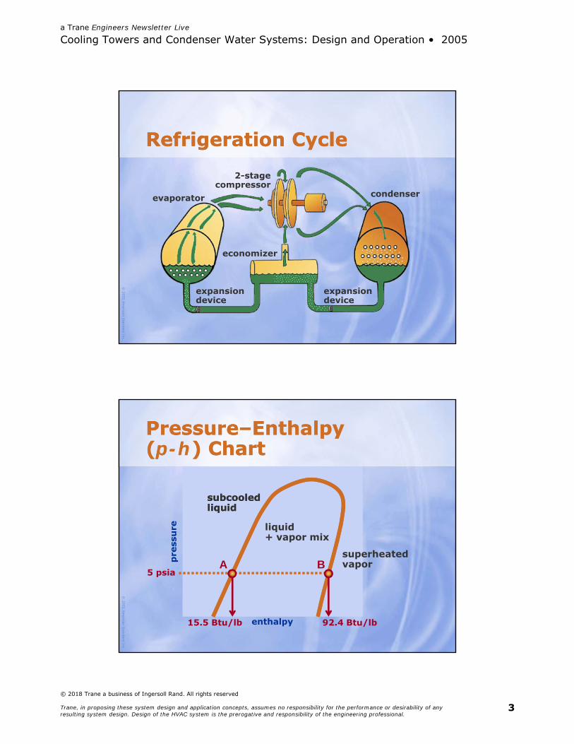
Refrigeration CycleRefrigeration Cycle
2-stagecompressor
evaporator condenser
economizer
expansiondevice
expansiondevice
© 2005
Am
erican Standard Inc.
Pressure–Enthalpy(p-h) ChartPressure–Enthalpy(p-h) Chart
enthalpy
subcooledliquidsubcooledliquid
liquid+ vapor mix
pre
ssu
re
superheatedvaporB
92.4 Btu/lb15.5 Btu/lb
A5 psia

a Trane Engineers Newsletter Live
Cooling Towers and Condenser Water Systems: Design and Operation • 2005
© 2018 Trane a business of Ingersoll Rand. All rights reserved
Trane, in proposing these system design and application concepts, assumes no responsibility for the performance or desirability of any resulting system design. Design of the HVAC system is the prerogative and responsibility of the engineering professional.
4
© 2005
Am
erican Standard Inc.
2-stage centrifugal chillerRefrigeration Cycle2-stage centrifugal chillerRefrigeration Cycle
enthalpy
pre
ssu
re expansiondevices
evaporator
economizer
condenser
9
87
65
Pe 1
3P1
2-stagecompressor
2
Pc4
© 2005
Am
erican Standard Inc.
2-stage centrifugal chillerRefrigeration Cycle2-stage centrifugal chillerRefrigeration Cycle
enthalpy
pre
ssu
re expansiondevices
evaporator
economizer
Pc
condenser
Pe
P12-stagecompressor
4
1
4'

a Trane Engineers Newsletter Live
Cooling Towers and Condenser Water Systems: Design and Operation • 2005
© 2018 Trane a business of Ingersoll Rand. All rights reserved
Trane, in proposing these system design and application concepts, assumes no responsibility for the performance or desirability of any resulting system design. Design of the HVAC system is the prerogative and responsibility of the engineering professional.
5
© 2005
Am
erican Standard Inc.
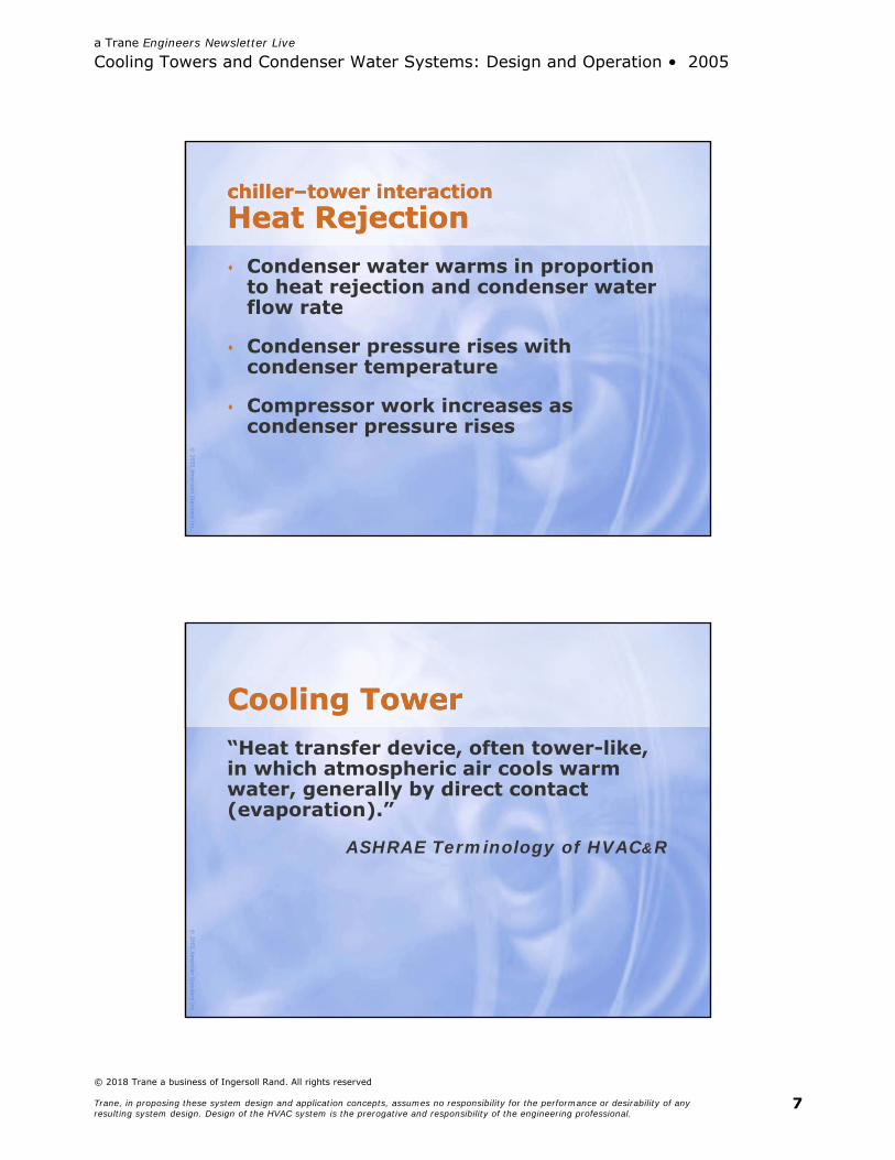
chiller–tower interactionHeat Rejectionchiller–tower interactionHeat Rejection Tower determines return condenser
water temperature
Chiller determines required heat rejection rate of tower
Hermetic motor:100% of electricalinput
Open motor:electrical input× motor efficiency
Evaporator load+
Compressor energy
© 2005
Am
erican Standard Inc.
chiller–tower interactionHeat Rejection, Qchiller–tower interactionHeat Rejection, Q
Q = evaporator load + input energy
or
Q = evaporator load × (1 + 1/COP)

a Trane Engineers Newsletter Live
Cooling Towers and Condenser Water Systems: Design and Operation • 2005
© 2018 Trane a business of Ingersoll Rand. All rights reserved
Trane, in proposing these system design and application concepts, assumes no responsibility for the performance or desirability of any resulting system design. Design of the HVAC system is the prerogative and responsibility of the engineering professional.
6
© 2005
Am
erican Standard Inc.
electric chillerHeat Rejection Exampleelectric chillerHeat Rejection ExampleFor 1 ton of evaporator load:
Q = 12,000 Btu/h × (1 + 1/6.10)= 12,000 Btu/h × (1 + 0.16)= 13,967 Btu/h
© 2005
Am
erican Standard Inc.
For 1 ton of evaporator load, condenserwater temperature rises …
… 9.3°F at 3 gpm/tonT = 13,967 / (500 × 3) = 9.3F
electric chillerHeat Rejection Exampleelectric chillerHeat Rejection Example
… 14.0°F at 2 gpm/tonT = 14,000 / (500 × 2) = 14.0F
T = Q (Btu/h) / (500 × gpm)
a Trane Engineers Newsletter Live
Cooling Towers and Condenser Water Systems: Design and Operation • 2005
© 2018 Trane a business of Ingersoll Rand. All rights reserved
Trane, in proposing these system design and application concepts, assumes no responsibility for the performance or desirability of any resulting system design. Design of the HVAC system is the prerogative and responsibility of the engineering professional.
7
© 2005
Am
erican Standard Inc.
chiller–tower interactionHeat Rejectionchiller–tower interactionHeat Rejection Condenser water warms in proportion
to heat rejection and condenser water flow rate
Condenser pressure rises with condenser temperature
Compressor work increases as condenser pressure rises
© 2005
Am
erican Standard Inc.
Cooling TowerCooling Tower“Heat transfer device, often tower-like, in which atmospheric air cools warm water, generally by direct contact (evaporation).”
ASHRAE Terminology of HVAC&R
a Trane Engineers Newsletter Live
Cooling Towers and Condenser Water Systems: Design and Operation • 2005
© 2018 Trane a business of Ingersoll Rand. All rights reserved
Trane, in proposing these system design and application concepts, assumes no responsibility for the performance or desirability of any resulting system design. Design of the HVAC system is the prerogative and responsibility of the engineering professional.
8
© 2005
Am
erican Standard Inc.
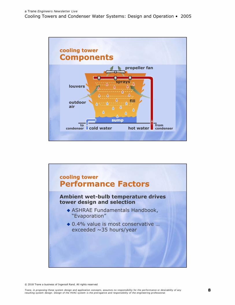
cooling towerComponentscooling towerComponents
sprays
sumpsump
outdoorair
louvers
hot water
fill
tocondenser cold water
fromcondenser
propeller fan
© 2005
Am
erican Standard Inc.
cooling towerPerformance Factorscooling towerPerformance FactorsAmbient wet-bulb temperature drives tower design and selection ASHRAE Fundamentals Handbook,
“Evaporation” 0.4% value is most conservative …
exceeded ~35 hours/year

a Trane Engineers Newsletter Live
Cooling Towers and Condenser Water Systems: Design and Operation • 2005
© 2018 Trane a business of Ingersoll Rand. All rights reserved
Trane, in proposing these system design and application concepts, assumes no responsibility for the performance or desirability of any resulting system design. Design of the HVAC system is the prerogative and responsibility of the engineering professional.
9
© 2005
Am
erican Standard Inc.
cooling towerPerformance Factorscooling towerPerformance Factors
hot watertemperature
cold watertemperature
ambient wet bulb
towerflow rate
range
approach
© 2005
Am
erican Standard Inc.
cooling tower certificationCTI Performance Limitscooling tower certificationCTI Performance Limits
hot water< 125°F
cold watertemperature
ambient 60°F–90°F WB
Cooling Technology Institute (CTI)may certify tower performance
range > 4°F
approach > 5°F

a Trane Engineers Newsletter Live
Cooling Towers and Condenser Water Systems: Design and Operation • 2005
© 2018 Trane a business of Ingersoll Rand. All rights reserved
Trane, in proposing these system design and application concepts, assumes no responsibility for the performance or desirability of any resulting system design. Design of the HVAC system is the prerogative and responsibility of the engineering professional.
10
© 2005
Am
erican Standard Inc.
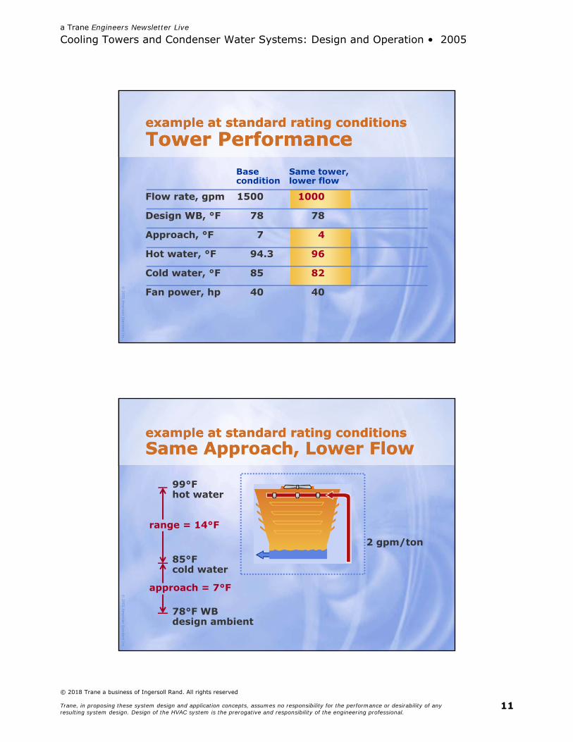
example at standard rating conditionsTower Performanceexample at standard rating conditionsTower Performance
Flow rate, gpm 1500
Design WB, °F 78
Approach, °F 7
Hot water, °F 94.3
Cold water, °F 85
Fan power, hp 40
Basecondition
© 2005
Am
erican Standard Inc.
example at standard rating conditionsSame Tower, Lower Flowexample at standard rating conditionsSame Tower, Lower Flow
96°Fhot water
82°Fcold water
78°F WBdesign ambient
range = 14°F
approach = 4°F
2 gpm/ton
a Trane Engineers Newsletter Live
Cooling Towers and Condenser Water Systems: Design and Operation • 2005
© 2018 Trane a business of Ingersoll Rand. All rights reserved
Trane, in proposing these system design and application concepts, assumes no responsibility for the performance or desirability of any resulting system design. Design of the HVAC system is the prerogative and responsibility of the engineering professional.
11
© 2005
Am
erican Standard Inc.
Base Same tower,condition lower flow
example at standard rating conditionsTower Performanceexample at standard rating conditionsTower Performance
Flow rate, gpm 1500 1000
Design WB, °F 78 78
Approach, °F 7 4
Hot water, °F 94.3 96
Cold water, °F 85 82
Fan power, hp 40 40
© 2005
Am
erican Standard Inc.
example at standard rating conditionsSame Approach, Lower Flowexample at standard rating conditionsSame Approach, Lower Flow
99°Fhot water
85°Fcold water
78°F WBdesign ambient
range = 14°F
approach = 7°F
2 gpm/ton

a Trane Engineers Newsletter Live
Cooling Towers and Condenser Water Systems: Design and Operation • 2005
© 2018 Trane a business of Ingersoll Rand. All rights reserved
Trane, in proposing these system design and application concepts, assumes no responsibility for the performance or desirability of any resulting system design. Design of the HVAC system is the prerogative and responsibility of the engineering professional.
12
© 2005
Am
erican Standard Inc.
Flow rate, gpm 1500 1000 1000
Design WB, °F 78 78 78
Approach, °F 7 4 7
Hot water, °F 94.3 96 99
Cold water, °F 85 82 85
Fan power, hp 40 40 25
example at standard rating conditionsTower Performanceexample at standard rating conditionsTower Performance
Base Same tower, Smaller tower,condition lower flow lower flow
© 2005
Am
erican Standard Inc.
cooling tower performance factorsApproach and Rangecooling tower performance factorsApproach and Range
ambient wet bulb, °F
0.0
4.0
8.0
12.0
16.0
50 60 70 80
tow
er a
pp
roac
h,
deg
100% load
50% load
approach = 4
approach = 7
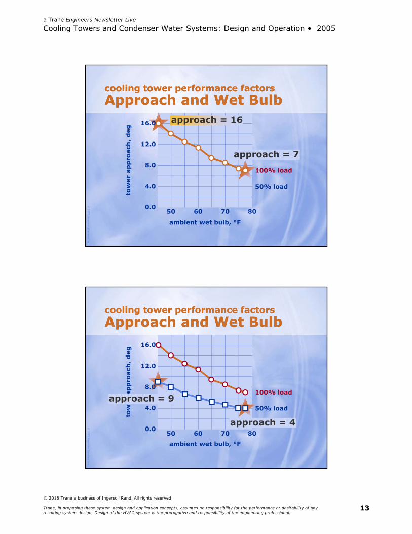
a Trane Engineers Newsletter Live
Cooling Towers and Condenser Water Systems: Design and Operation • 2005
© 2018 Trane a business of Ingersoll Rand. All rights reserved
Trane, in proposing these system design and application concepts, assumes no responsibility for the performance or desirability of any resulting system design. Design of the HVAC system is the prerogative and responsibility of the engineering professional.
13
© 2005
Am
erican Standard Inc.
ambient wet bulb, °F
0.0
4.0
8.0
12.0
16.0
50 60 70 80
tow
er a
pp
roac
h,
deg
100% load
50% load
cooling tower performance factorsApproach and Wet Bulbcooling tower performance factorsApproach and Wet Bulb
approach = 7
approach = 16
© 2005
Am
erican Standard Inc.
ambient wet bulb, °F
0.0
4.0
8.0
12.0
16.0
50 60 70 80
tow
er a
pp
roac
h,
deg
100% load
50% load
approach = 4
approach = 9
cooling tower performance factorsApproach and Wet Bulbcooling tower performance factorsApproach and Wet Bulb
a Trane Engineers Newsletter Live
Cooling Towers and Condenser Water Systems: Design and Operation • 2005
© 2018 Trane a business of Ingersoll Rand. All rights reserved
Trane, in proposing these system design and application concepts, assumes no responsibility for the performance or desirability of any resulting system design. Design of the HVAC system is the prerogative and responsibility of the engineering professional.
14
© 2005 American Standard Inc.
Cooling Towers and Condenser Water SystemsDesign and Operation
Designconditions
© 2005
Am
erican Standard Inc.
a design issueFlow Ratesa design issueFlow Rates Past rule of thumb: 3 gpm/ton 10° F ΔT for older, less efficient chillers ~9°F ΔT for currently produced chillers
Today’s design advice Reduce flow rates Increase temperature differences

a Trane Engineers Newsletter Live
Cooling Towers and Condenser Water Systems: Design and Operation • 2005
© 2018 Trane a business of Ingersoll Rand. All rights reserved
Trane, in proposing these system design and application concepts, assumes no responsibility for the performance or desirability of any resulting system design. Design of the HVAC system is the prerogative and responsibility of the engineering professional.
15
© 2005
Am
erican Standard Inc.
increase T, reduce flow rateCondenser Waterincrease T, reduce flow rateCondenser WaterIndustry advisor
Pacific Gas andElectric CoolTools™
Recommendation
10°–15°F T single stage12°–18°F T multistage or positive displacement
Kelly and Chan 14.2°F T for 3.6–8.3% energy savings in various climates
ASHRAE Green Guide 12°–18°F T
© 2005
Am
erican Standard Inc.
a history ofChiller Performancea history ofChiller Performance
8.0
ASHRAE Standard 90
chill
er e
ffic
ien
cy,
CO
P
6.0
4.0
2.0
0.0NBI “best”
available90-75(1977)
90-75(1980)
90.1-89 90.1-99
centrifugal>600 tons
screw150-300 tons
scroll<100 tons
reciprocating<150 tons

a Trane Engineers Newsletter Live
Cooling Towers and Condenser Water Systems: Design and Operation • 2005
© 2018 Trane a business of Ingersoll Rand. All rights reserved
Trane, in proposing these system design and application concepts, assumes no responsibility for the performance or desirability of any resulting system design. Design of the HVAC system is the prerogative and responsibility of the engineering professional.
16
© 2005
Am
erican Standard Inc.
chilled water plant designCondensing Componentschilled water plant designCondensing Components
Chiller
Condenser waterpump
Cooling tower
© 2005
Am
erican Standard Inc.
chilled water plant designChiller Selectionchilled water plant designChiller Selection
Certified selections help assure expectedchiller performance
Full-load and part-load conditions Air-Conditioning & Refrigeration
Institute (ARI)

a Trane Engineers Newsletter Live
Cooling Towers and Condenser Water Systems: Design and Operation • 2005
© 2018 Trane a business of Ingersoll Rand. All rights reserved
Trane, in proposing these system design and application concepts, assumes no responsibility for the performance or desirability of any resulting system design. Design of the HVAC system is the prerogative and responsibility of the engineering professional.
17
© 2005
Am
erican Standard Inc.
chilled water plant designCooling Tower Selectionchilled water plant designCooling Tower Selection
Cooling Technology Institute (CTI)rates tower performance
© 2005
Am
erican Standard Inc.
chilled water plant designPump Selectionchilled water plant designPump Selection
hp = gpm × P3960 × pump efficiency
kW =motor efficiency
0.746 × hp
a Trane Engineers Newsletter Live
Cooling Towers and Condenser Water Systems: Design and Operation • 2005
© 2018 Trane a business of Ingersoll Rand. All rights reserved
Trane, in proposing these system design and application concepts, assumes no responsibility for the performance or desirability of any resulting system design. Design of the HVAC system is the prerogative and responsibility of the engineering professional.
18
© 2005
Am
erican Standard Inc.
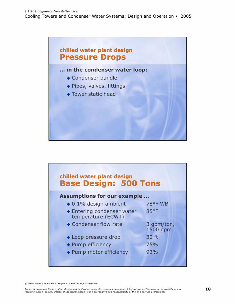
chilled water plant designPressure Dropschilled water plant designPressure Drops… in the condenser water loop: Condenser bundle Pipes, valves, fittings Tower static head
© 2005
Am
erican Standard Inc.
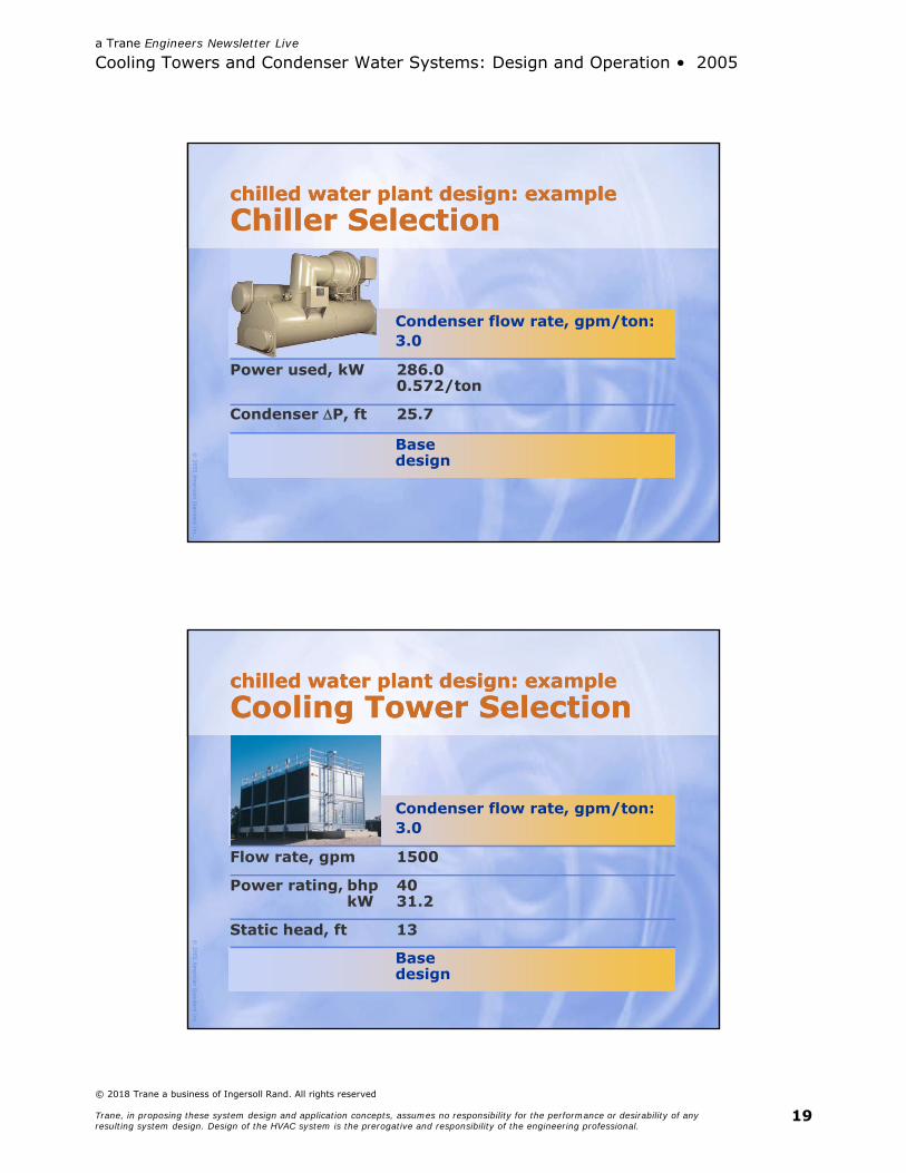
chilled water plant designBase Design: 500 Tonschilled water plant designBase Design: 500 TonsAssumptions for our example … 0.1% design ambient 78°F WB Entering condenser water 85°F
temperature (ECWT) Condenser flow rate 3 gpm/ton,
1500 gpm Loop pressure drop 30 ft Pump efficiency 75% Pump motor efficiency 93%
a Trane Engineers Newsletter Live
Cooling Towers and Condenser Water Systems: Design and Operation • 2005
© 2018 Trane a business of Ingersoll Rand. All rights reserved
Trane, in proposing these system design and application concepts, assumes no responsibility for the performance or desirability of any resulting system design. Design of the HVAC system is the prerogative and responsibility of the engineering professional.
19
© 2005
Am
erican Standard Inc.
chilled water plant design: exampleChiller Selectionchilled water plant design: exampleChiller Selection
Basedesign
Power used, kW 286.00.572/ton
Condenser P, ft 25.7
Condenser flow rate, gpm/ton:3.0
© 2005
Am
erican Standard Inc.
chilled water plant design: exampleCooling Tower Selectionchilled water plant design: exampleCooling Tower Selection
Flow rate, gpm 1500
Power rating, bhp 40kW 31.2
Static head, ft 13
Condenser flow rate, gpm/ton:3.0
Basedesign
a Trane Engineers Newsletter Live
Cooling Towers and Condenser Water Systems: Design and Operation • 2005
© 2018 Trane a business of Ingersoll Rand. All rights reserved
Trane, in proposing these system design and application concepts, assumes no responsibility for the performance or desirability of any resulting system design. Design of the HVAC system is the prerogative and responsibility of the engineering professional.
20
© 2005
Am
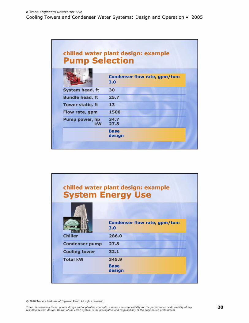
erican Standard Inc.
System head, ft 30
Bundle head, ft 25.7
Tower static, ft 13
Flow rate, gpm 1500
Pump power, hp 34.7kW 27.8
Condenser flow rate, gpm/ton:3.0
Basedesign
chilled water plant design: examplePump Selectionchilled water plant design: examplePump Selection
© 2005
Am
erican Standard Inc.
chilled water plant design: exampleSystem Energy Usechilled water plant design: exampleSystem Energy Use
Chiller 286.0
Condenser pump 27.8
Cooling tower 32.1
Total kW 345.9
Condenser flow rate, gpm/ton:3.0
Basedesign

a Trane Engineers Newsletter Live
Cooling Towers and Condenser Water Systems: Design and Operation • 2005
© 2018 Trane a business of Ingersoll Rand. All rights reserved
Trane, in proposing these system design and application concepts, assumes no responsibility for the performance or desirability of any resulting system design. Design of the HVAC system is the prerogative and responsibility of the engineering professional.
21
© 2005
Am
erican Standard Inc.
chilled water plant design: exampleReduce Flow Ratechilled water plant design: exampleReduce Flow Rate Assumptions that won’t change … Pipes
(Head varies with square of flow) Chiller cost
What we’ll alter … Condenser flow Cooling tower size, as appropriate
© 2005
Am
erican Standard Inc.
chilled water plant design: exampleChiller Selectionchilled water plant design: exampleChiller Selection
Base Reduceddesign flow
Power used, kW 286.0 307.00.572/ton 0.614/ton
Condenser P, ft 25.7 17.7
Condenser flow rate, gpm/ton:3.0 2.0
a Trane Engineers Newsletter Live
Cooling Towers and Condenser Water Systems: Design and Operation • 2005
© 2018 Trane a business of Ingersoll Rand. All rights reserved
Trane, in proposing these system design and application concepts, assumes no responsibility for the performance or desirability of any resulting system design. Design of the HVAC system is the prerogative and responsibility of the engineering professional.
22
© 2005
Am
erican Standard Inc.
chilled water plant design: exampleCooling Tower Selectionchilled water plant design: exampleCooling Tower Selection
Flow rate, gpm 1500 1000
Power rating, bhp 40 25kW 31.2 20
Static head, ft 13 13
Condenser flow rate, gpm/ton:3.0 2.0
Base Reduceddesign flow
Costs 10% lessthan base
© 2005
Am
erican Standard Inc.
chilled water plant design: examplePump Selectionchilled water plant design: examplePump Selection
System head, ft 30 13.3
Bundle head, ft 25.7 17.7
Tower static, ft 13 13
Flow rate, gpm 1500 1000
Pump power, hp 34.7kW 27.8 10.7
Condenser flow rate, gpm/ton:3.0 2.0
Base Reduceddesign flow
(500 × 2.0)
(30 × [2.0/3.0]²)
a Trane Engineers Newsletter Live
Cooling Towers and Condenser Water Systems: Design and Operation • 2005
© 2018 Trane a business of Ingersoll Rand. All rights reserved
Trane, in proposing these system design and application concepts, assumes no responsibility for the performance or desirability of any resulting system design. Design of the HVAC system is the prerogative and responsibility of the engineering professional.
23
© 2005
Am
erican Standard Inc.
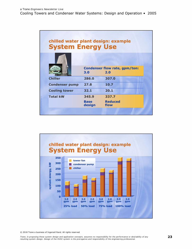
chilled water plant design: exampleSystem Energy Usechilled water plant design: exampleSystem Energy Use
Chiller 286.0 307.0
Condenser pump 27.8 10.7
Cooling tower 32.1 20.1
Total kW 345.9 337.7
Condenser flow rate, gpm/ton:3.0 2.0
Base Reduceddesign flow
© 2005
Am
erican Standard Inc.
chilled water plant design: exampleSystem Energy Usechilled water plant design: exampleSystem Energy Use
350
25% load
syst
em e
ner
gy,
kW
3.0gpm
300
250
200
150
100
50
0
tower fancondenser pumpchiller
2.0gpm
3.0gpm
2.0gpm
3.0gpm
2.0gpm
3.0gpm
2.0gpm
50% load 75% load 100% load
a Trane Engineers Newsletter Live
Cooling Towers and Condenser Water Systems: Design and Operation • 2005
© 2018 Trane a business of Ingersoll Rand. All rights reserved
Trane, in proposing these system design and application concepts, assumes no responsibility for the performance or desirability of any resulting system design. Design of the HVAC system is the prerogative and responsibility of the engineering professional.
24
© 2005
Am
erican Standard Inc.
chilled water plant designOptionschilled water plant designOptions Downsize pumps and tower to take
full energy cost savings OR Reduce pipe size to cut installed cost Reduces structural costs (tower, pipes,
water in pipes) Can reinvest part of savings in more
efficient chiller Reduces pump savings
© 2005
Am
erican Standard Inc.
Is reduced flow only for long piping runs?Is reduced flow only for long piping runs?
Condenser water pump must overcome pressure drops Condenser bundle Tower static lift Pipes, valves, fittings
What if it was0 ft of head?
a Trane Engineers Newsletter Live
Cooling Towers and Condenser Water Systems: Design and Operation • 2005
© 2018 Trane a business of Ingersoll Rand. All rights reserved
Trane, in proposing these system design and application concepts, assumes no responsibility for the performance or desirability of any resulting system design. Design of the HVAC system is the prerogative and responsibility of the engineering professional.
25
© 2005
Am
erican Standard Inc.
Reduced flow worksfor short runs, too!Reduced flow worksfor short runs, too!
350
25% load
syst
em e
ner
gy,
kW
3.0gpm
300
250
200
150
100
50
0
tower fancondenser pumpchiller
2.0gpm
3.0gpm
2.0gpm
3.0gpm
2.0gpm
3.0gpm
2.0gpm
50% load 75% load 100% load
*piping PD = 0 ft
© 2005
Am
erican Standard Inc.
Does reduced flow work for all chillers?Does reduced flow work for all chillers?
Logan Airport, BostonCost savings: $426,000 construction
7.3% operation
DuPont, GreenvilleCost savings: $45,000 excavation, concrete
6.5% operation
Hewlett Packard, San FranciscoCost savings: Piping
2% operation (existing tower)

a Trane Engineers Newsletter Live
Cooling Towers and Condenser Water Systems: Design and Operation • 2005
© 2018 Trane a business of Ingersoll Rand. All rights reserved
Trane, in proposing these system design and application concepts, assumes no responsibility for the performance or desirability of any resulting system design. Design of the HVAC system is the prerogative and responsibility of the engineering professional.
26
© 2005
Am
erican Standard Inc.
Proven savings for all manufacturersProven savings for all manufacturers
Logan Airport, BostonCost savings: $426,000 construction
7.3% operation
DuPont, GreenvilleCost savings: $45,000 excavation, concrete
6.5% operation
Hewlett Packard, San FranciscoCost savings: Piping
2% operation (existing tower)
© 2005
Am
erican Standard Inc.
Does reduced flow work for retrofits?Does reduced flow work for retrofits?
Opportunity: Chiller must be replaced Cooling needs increased by 50% Cooling tower was replaced
two years ago Condenser pump and pipes
in good shape
a Trane Engineers Newsletter Live
Cooling Towers and Condenser Water Systems: Design and Operation • 2005
© 2018 Trane a business of Ingersoll Rand. All rights reserved
Trane, in proposing these system design and application concepts, assumes no responsibility for the performance or desirability of any resulting system design. Design of the HVAC system is the prerogative and responsibility of the engineering professional.
27
© 2005
Am
erican Standard Inc.
Capacity, tons 500 750
Flow rate, gpm 1500 1500
Condenser water:entering, °F 85 88leaving, °F 95 102.4
Design wet bulb, °F 78 78
Condenser-side opportunity:Existing Retrofit
Reduced flow can aid retrofit budgetsReduced flow can aid retrofit budgets
© 2005
Am
erican Standard Inc.
chilled water plant designAnalysis Toolschilled water plant designAnalysis Tools System
Analyzer™
Chiller PlantAnalyzer
TRACE™ 700
DOE 2.1
HAPOADB does not correlate directly to load!

a Trane Engineers Newsletter Live
Cooling Towers and Condenser Water Systems: Design and Operation • 2005
© 2018 Trane a business of Ingersoll Rand. All rights reserved
Trane, in proposing these system design and application concepts, assumes no responsibility for the performance or desirability of any resulting system design. Design of the HVAC system is the prerogative and responsibility of the engineering professional.
28
© 2005
Am
erican Standard Inc.
Reduced flow saves installed and operating costs
No “magic” flow rate …Start at 2 gpm/ton and adjust
Reinvest part of first-cost savings in more efficient chillers
chilled water plant designGuidancechilled water plant designGuidance
© 2005
Am
erican Standard Inc.
always, always, ALWAYSRemember …always, always, ALWAYSRemember …
The meter is onthe BUILDING
a Trane Engineers Newsletter Live
Cooling Towers and Condenser Water Systems: Design and Operation • 2005
© 2018 Trane a business of Ingersoll Rand. All rights reserved
Trane, in proposing these system design and application concepts, assumes no responsibility for the performance or desirability of any resulting system design. Design of the HVAC system is the prerogative and responsibility of the engineering professional.
29
© 2005
Am
erican Standard Inc.
a win-win-win situationSaving Energy–And Morea win-win-win situationSaving Energy–And More“In addition to the electric energy savings, this chiller plant will have prevented the emissions of 1.1 million lb of CO2 per year, 8,800 lb of SO2 per year, and 3,100 lb of NOx per year. This is an overall win-win-win situation where the first cost is reduced, operating cost is minimized, plus significant environmental benefits are realized as an additional benefit.”
from “A Chiller Challenge” by T. Chan
© 2005 American Standard Inc.
Cooling Towers and Condenser Water SystemsDesign and Operation
Cooling-towercontrol options

a Trane Engineers Newsletter Live
Cooling Towers and Condenser Water Systems: Design and Operation • 2005
© 2018 Trane a business of Ingersoll Rand. All rights reserved
Trane, in proposing these system design and application concepts, assumes no responsibility for the performance or desirability of any resulting system design. Design of the HVAC system is the prerogative and responsibility of the engineering professional.
30
© 2005
Am
erican Standard Inc.
chiller–tower optimizationControlchiller–tower optimizationControl Capacity Design requirements Tower control options Sequence to conserve energy
System protection Chiller requirements Tower requirements
© 2005
Am
erican Standard Inc.
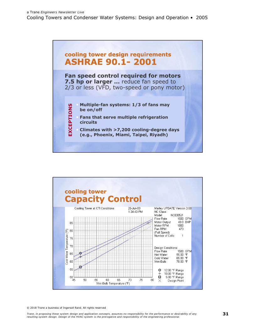
cooling tower design requirementsASHRAE 90.1-2001cooling tower design requirementsASHRAE 90.1-2001
Maximum allowable fan power … Centrifugal fan < 20.0 gpm/hp Propeller or axial fan < 38.2 gpm/hp
… at 95°F EWT/85°F LWT/75°F WB
a Trane Engineers Newsletter Live
Cooling Towers and Condenser Water Systems: Design and Operation • 2005
© 2018 Trane a business of Ingersoll Rand. All rights reserved
Trane, in proposing these system design and application concepts, assumes no responsibility for the performance or desirability of any resulting system design. Design of the HVAC system is the prerogative and responsibility of the engineering professional.
31
© 2005
Am
erican Standard Inc.
cooling tower design requirementsASHRAE 90.1- 2001cooling tower design requirementsASHRAE 90.1- 2001Fan speed control required for motors 7.5 hp or larger … reduce fan speed to2/3 or less (VFD, two-speed or pony motor)
• Multiple-fan systems: 1/3 of fans maybe on/off
• Fans that serve multiple refrigeration circuits
• Climates with >7,200 cooling-degree days (e.g., Phoenix, Miami, Taipei, Riyadh)EX
CEP
TIO
NS
© 2005
Am
erican Standard Inc.
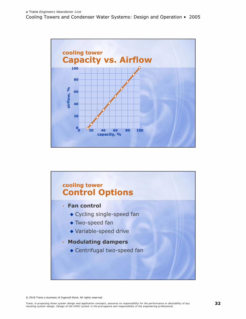
cooling towerCapacity Controlcooling towerCapacity Control
a Trane Engineers Newsletter Live
Cooling Towers and Condenser Water Systems: Design and Operation • 2005
© 2018 Trane a business of Ingersoll Rand. All rights reserved
Trane, in proposing these system design and application concepts, assumes no responsibility for the performance or desirability of any resulting system design. Design of the HVAC system is the prerogative and responsibility of the engineering professional.
32
© 2005
Am
erican Standard Inc.
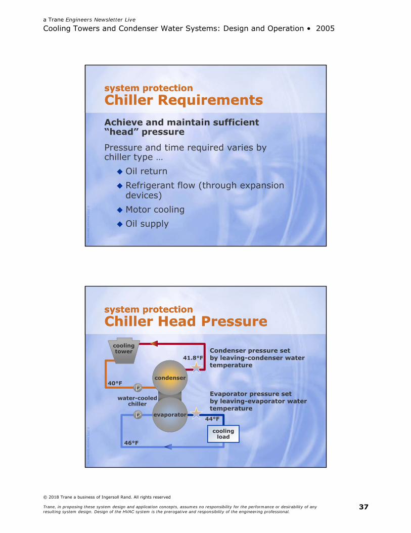
capacity, %
100
20
airf
low
, %
cooling towerCapacity vs. Airflowcooling towerCapacity vs. Airflow
40 60 80 1000
80
60
40
20
0
© 2005
Am
erican Standard Inc.
cooling towerControl Optionscooling towerControl Options Fan control Cycling single-speed fan Two-speed fan Variable-speed drive
Modulating dampers Centrifugal two-speed fan

a Trane Engineers Newsletter Live
Cooling Towers and Condenser Water Systems: Design and Operation • 2005
© 2018 Trane a business of Ingersoll Rand. All rights reserved
Trane, in proposing these system design and application concepts, assumes no responsibility for the performance or desirability of any resulting system design. Design of the HVAC system is the prerogative and responsibility of the engineering professional.
33
© 2005
Am
erican Standard Inc.
capacity, %
100
20airf
low
AN
D f
ull-
load
pow
er,
%
40 60 80 1000
80
60
40
20
0
one tower fanPerfect Capacity Controlone tower fanPerfect Capacity Control
capacity vs. airflowairflow vs. fan power
variable-speed drive
© 2005
Am
erican Standard Inc.
capacity, %
100
20
full-
load
pow
er,
%
40 60 80 1000
80
60
40
20
0
variable-speed drive
single-speed fan
one tower fanCapacity Controlone tower fanCapacity Control
two-speed fan:100% and 50%
two-speed fan:100% and 67%

a Trane Engineers Newsletter Live
Cooling Towers and Condenser Water Systems: Design and Operation • 2005
© 2018 Trane a business of Ingersoll Rand. All rights reserved
Trane, in proposing these system design and application concepts, assumes no responsibility for the performance or desirability of any resulting system design. Design of the HVAC system is the prerogative and responsibility of the engineering professional.
34
© 2005
Am
erican Standard Inc.
capacity, %
100
20
full-
load
pow
er,
%
40 60 80 1000
80
60
40
20
0
2 fans with VSDs
2 single-speed fans
1 single-speed fan,1 two-speed fan
two tower fansCapacity Controltwo tower fansCapacity Control
© 2005
Am
erican Standard Inc.
capacity, %
100
20
full-
load
pow
er,
%
40 60 80 1000
80
60
40
20
0
2 fans with VSDs,modulated together2 fans with VSDs,1 to high speed first
two tower fansCapacity Controltwo tower fansCapacity Control

a Trane Engineers Newsletter Live
Cooling Towers and Condenser Water Systems: Design and Operation • 2005
© 2018 Trane a business of Ingersoll Rand. All rights reserved
Trane, in proposing these system design and application concepts, assumes no responsibility for the performance or desirability of any resulting system design. Design of the HVAC system is the prerogative and responsibility of the engineering professional.
35
© 2005
Am
erican Standard Inc.
cooling towerRules for Capacity Controlcooling towerRules for Capacity Control ASHARE 90.1 requirements
make sense
Invest in VFDs on all tower fans
Operating multiple fans at part speed saves energy Consumes less power than one fan at
full speed and the other off
© 2005
Am
erican Standard Inc.
cooling tower capacity controlSequence of Operationcooling tower capacity controlSequence of Operation1. When a chiller is operating and the cooling tower basin
temperature rises to two (2) degrees F above the current tower leaving water setpoint, the lead cooling tower fan shall be turned on at minimum speed and the DDC control loop enabled.
a. When the operating fan(s) are operating at 50 percent speed, an additional fan shall be enabled and controlled at the same speed as the operating fans until all active cooling tower cell fans are enabled.
b. When operating fans are running at minimum speed and the tower supply water temperature is five (5) degrees below the current tower leaving water setpoint, the most lag tower fan shall be turned off.
c. Cooling tower fans shall have five (5) minute minimum on and off time delays.

a Trane Engineers Newsletter Live
Cooling Towers and Condenser Water Systems: Design and Operation • 2005
© 2018 Trane a business of Ingersoll Rand. All rights reserved
Trane, in proposing these system design and application concepts, assumes no responsibility for the performance or desirability of any resulting system design. Design of the HVAC system is the prerogative and responsibility of the engineering professional.
36
© 2005
Am
erican Standard Inc.
chiller–tower optimizationControlchiller–tower optimizationControl Capacity Design requirements Tower control options Sequence to conserve energy
System protection Chiller requirements Tower requirements
© 2005
Am
erican Standard Inc.
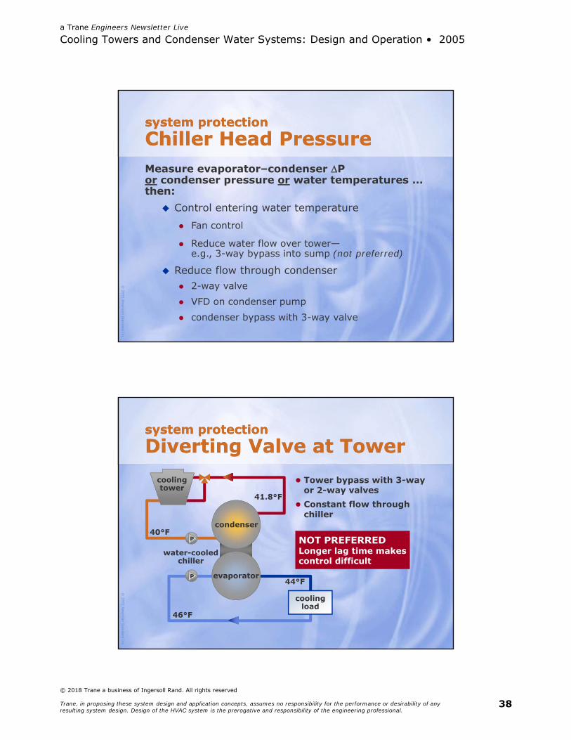
system protectionChiller Head Pressuresystem protectionChiller Head Pressure
coolingtower
water-cooledchiller
coolingload
P
P44°F
46°F
40°Fcondenser
evaporator
Condenser pressure setby leaving-condenser watertemperature
Evaporator pressure setby leaving-evaporator watertemperature
41.8°F
a Trane Engineers Newsletter Live
Cooling Towers and Condenser Water Systems: Design and Operation • 2005
© 2018 Trane a business of Ingersoll Rand. All rights reserved
Trane, in proposing these system design and application concepts, assumes no responsibility for the performance or desirability of any resulting system design. Design of the HVAC system is the prerogative and responsibility of the engineering professional.
37
© 2005
Am
erican Standard Inc.
system protectionChiller Requirementssystem protectionChiller RequirementsAchieve and maintain sufficient“head” pressure
Pressure and time required varies bychiller type … Oil return Refrigerant flow (through expansion
devices) Motor cooling Oil supply
© 2005
Am
erican Standard Inc.
system protectionChiller Head Pressuresystem protectionChiller Head Pressure
coolingtower
water-cooledchiller
coolingload
P
P44°F
46°F
40°Fcondenser
evaporator
Condenser pressure setby leaving-condenser watertemperature
Evaporator pressure setby leaving-evaporator watertemperature
41.8°F
a Trane Engineers Newsletter Live
Cooling Towers and Condenser Water Systems: Design and Operation • 2005
© 2018 Trane a business of Ingersoll Rand. All rights reserved
Trane, in proposing these system design and application concepts, assumes no responsibility for the performance or desirability of any resulting system design. Design of the HVAC system is the prerogative and responsibility of the engineering professional.
38
© 2005
Am
erican Standard Inc.
system protectionChiller Head Pressuresystem protectionChiller Head PressureMeasure evaporator–condenser Por condenser pressure or water temperatures … then:
Control entering water temperature
Fan control
Reduce water flow over tower—e.g., 3-way bypass into sump (not preferred)
Reduce flow through condenser 2-way valve VFD on condenser pump condenser bypass with 3-way valve
© 2005
Am
erican Standard Inc.
system protectionDiverting Valve at Towersystem protectionDiverting Valve at Tower
coolingtower
water-cooledchiller
coolingload
P
P44°F
46°F
40°Fcondenser
evaporator
41.8°F
Tower bypass with 3-wayor 2-way valves
Constant flow throughchiller
NOT PREFERREDLonger lag time makescontrol difficult
a Trane Engineers Newsletter Live
Cooling Towers and Condenser Water Systems: Design and Operation • 2005
© 2018 Trane a business of Ingersoll Rand. All rights reserved
Trane, in proposing these system design and application concepts, assumes no responsibility for the performance or desirability of any resulting system design. Design of the HVAC system is the prerogative and responsibility of the engineering professional.
39
© 2005
Am
erican Standard Inc.
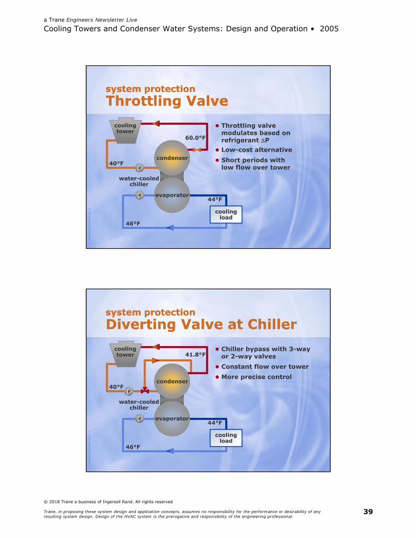
system protectionThrottling Valvesystem protectionThrottling Valve
coolingtower
water-cooledchiller
coolingload
P
P44°F
46°F
40°Fcondenser
evaporator
60.0°F
Throttling valvemodulates based onrefrigerant P
Low-cost alternative Short periods with
low flow over tower
© 2005
Am
erican Standard Inc.
system protectionDiverting Valve at Chillersystem protectionDiverting Valve at Chiller
coolingtower
water-cooledchiller
coolingload
P
P44°F
46°F
40°Fcondenser
evaporator
41.8°F Chiller bypass with 3-way
or 2-way valves Constant flow over tower More precise control
a Trane Engineers Newsletter Live
Cooling Towers and Condenser Water Systems: Design and Operation • 2005
© 2018 Trane a business of Ingersoll Rand. All rights reserved
Trane, in proposing these system design and application concepts, assumes no responsibility for the performance or desirability of any resulting system design. Design of the HVAC system is the prerogative and responsibility of the engineering professional.
40
© 2005
Am
erican Standard Inc.
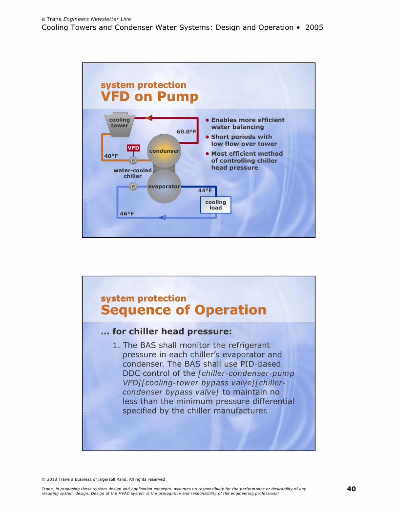
system protectionVFD on Pumpsystem protectionVFD on Pump
coolingtower
water-cooledchiller
coolingload
P
P44°F
46°F
40°Fcondenser
evaporator
60.0°F
Enables more efficientwater balancing
Short periods withlow flow over tower
Most efficient methodof controlling chillerhead pressure
VFD
© 2005
Am
erican Standard Inc.
system protectionSequence of Operationsystem protectionSequence of Operation… for chiller head pressure:
1. The BAS shall monitor the refrigerant pressure in each chiller’s evaporator and condenser. The BAS shall use PID-based DDC control of the [chiller-condenser-pump VFD][cooling-tower bypass valve][chiller-condenser bypass valve] to maintain no less than the minimum pressure differential specified by the chiller manufacturer.
a Trane Engineers Newsletter Live
Cooling Towers and Condenser Water Systems: Design and Operation • 2005
© 2018 Trane a business of Ingersoll Rand. All rights reserved
Trane, in proposing these system design and application concepts, assumes no responsibility for the performance or desirability of any resulting system design. Design of the HVAC system is the prerogative and responsibility of the engineering professional.
41
© 2005
Am
erican Standard Inc.
Trane literatureCondenser Water ControlTrane literatureCondenser Water Control
CTV-PRB006-ENCondenser Water Temperature Control for CenTraVac Centrifugal Chiller Systems
RLC-PRB017-ENWater-Cooled Series R Chiller Models RTHB & RTHD Condenser Water Control
© 2005
Am
erican Standard Inc.
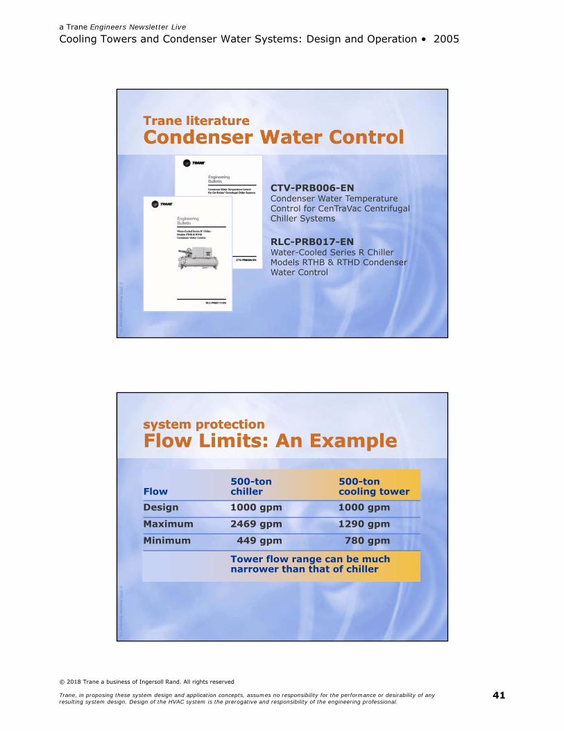
system protectionFlow Limits: An Examplesystem protectionFlow Limits: An Example
Design 1000 gpm 1000 gpm
Maximum 2469 gpm 1290 gpm
Minimum 449 gpm 780 gpm
500-tonchiller
Tower flow range can be muchnarrower than that of chiller
500-toncooling towerFlow
a Trane Engineers Newsletter Live
Cooling Towers and Condenser Water Systems: Design and Operation • 2005
© 2018 Trane a business of Ingersoll Rand. All rights reserved
Trane, in proposing these system design and application concepts, assumes no responsibility for the performance or desirability of any resulting system design. Design of the HVAC system is the prerogative and responsibility of the engineering professional.
42
© 2005
Am
erican Standard Inc.
system protectionTower Flow Limitssystem protectionTower Flow LimitsFlow violationToo low
Result “Holes” in fill coverage Lost efficiency Mineral deposits
Too high “Over-flow” distribution Lost efficiency Lost water Lost treatment
chemicals
Consult tower manufacturer … Specify limits
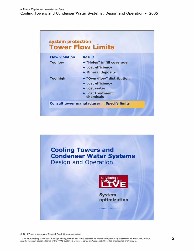
© 2005 American Standard Inc.
Cooling Towers and Condenser Water SystemsDesign and Operation
System optimization
a Trane Engineers Newsletter Live
Cooling Towers and Condenser Water Systems: Design and Operation • 2005
© 2018 Trane a business of Ingersoll Rand. All rights reserved
Trane, in proposing these system design and application concepts, assumes no responsibility for the performance or desirability of any resulting system design. Design of the HVAC system is the prerogative and responsibility of the engineering professional.
43
© 2005
Am
erican Standard Inc.
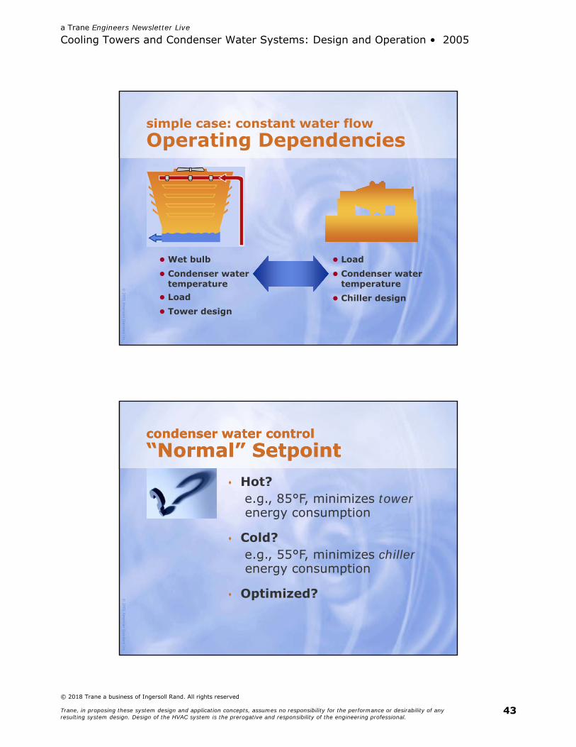
simple case: constant water flowOperating Dependencies
Wet bulb Condenser water
temperature Load Tower design
Load Condenser water
temperature Chiller design
© 2005
Am
erican Standard Inc.
condenser water control“Normal” Setpointcondenser water control“Normal” Setpoint
Hot?e.g., 85°F, minimizes towerenergy consumption
Cold?e.g., 55°F, minimizes chillerenergy consumption
Optimized?
a Trane Engineers Newsletter Live
Cooling Towers and Condenser Water Systems: Design and Operation • 2005
© 2018 Trane a business of Ingersoll Rand. All rights reserved
Trane, in proposing these system design and application concepts, assumes no responsibility for the performance or desirability of any resulting system design. Design of the HVAC system is the prerogative and responsibility of the engineering professional.
44
© 2005
Am
erican Standard Inc.
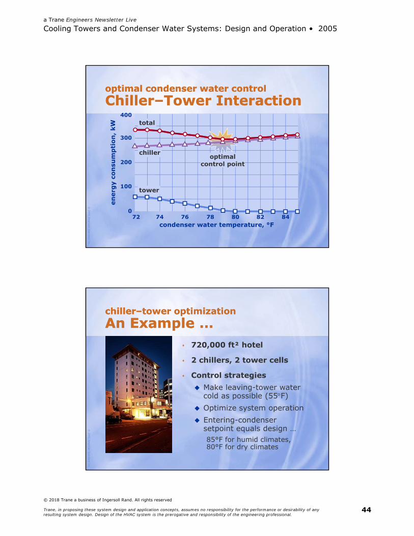
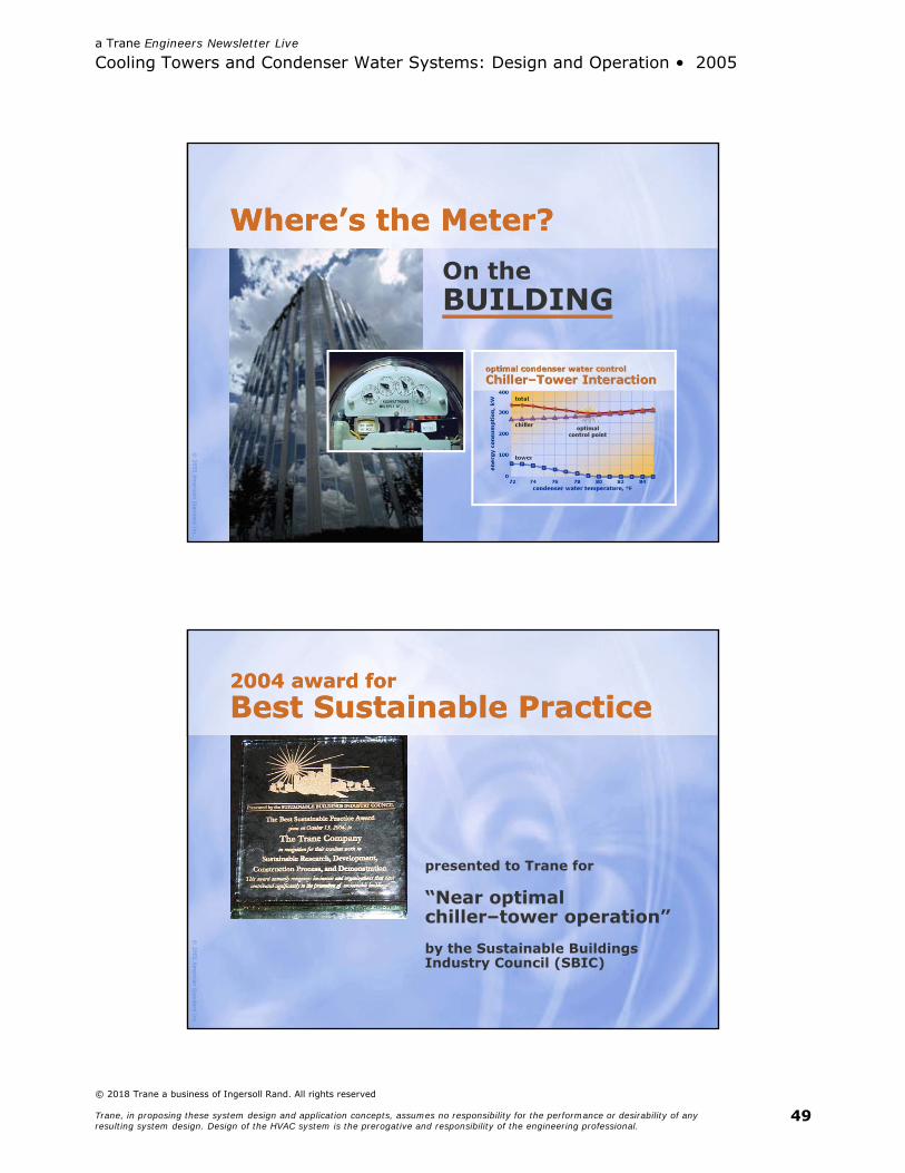
optimal condenser water controlChiller–Tower Interactionoptimal condenser water controlChiller–Tower Interaction
condenser water temperature, °F
400
74
ener
gy
con
sum
pti
on
, kW
76 78 80 8272
300
200
100
084
tower
chiller
total
optimalcontrol point
© 2005
Am
erican Standard Inc.
chiller–tower optimizationAn Example …chiller–tower optimizationAn Example …
720,000 ft² hotel
2 chillers, 2 tower cells
Control strategies Make leaving-tower water
cold as possible (55F) Optimize system operation Entering-condenser
setpoint equals design …85°F for humid climates,80°F for dry climates

a Trane Engineers Newsletter Live
Cooling Towers and Condenser Water Systems: Design and Operation • 2005
© 2018 Trane a business of Ingersoll Rand. All rights reserved
Trane, in proposing these system design and application concepts, assumes no responsibility for the performance or desirability of any resulting system design. Design of the HVAC system is the prerogative and responsibility of the engineering professional.
45
© 2005
Am
erican Standard Inc.
chiller–tower control strategiesNorth Americachiller–tower control strategiesNorth America
350Kan
nu
al o
per
atin
g c
ost
, $
US
D
300K
250K
200K
150K
100K
50K
0Mexico City Orlando San Diego Toronto
55°F lvg toweroptimal controldesign ECWT
control strategy:
© 2005
Am
erican Standard Inc.
ann
ual
op
erat
ing
cos
t, $
US
D
500K
400K
300K
200K
100K
0Dubai Paris Sao Paulo Singapore
55°F lvg toweroptimal controldesign ECWT
control strategy:
chiller–tower control strategiesGlobal Locationschiller–tower control strategiesGlobal Locations

a Trane Engineers Newsletter Live
Cooling Towers and Condenser Water Systems: Design and Operation • 2005
© 2018 Trane a business of Ingersoll Rand. All rights reserved
Trane, in proposing these system design and application concepts, assumes no responsibility for the performance or desirability of any resulting system design. Design of the HVAC system is the prerogative and responsibility of the engineering professional.
46
© 2005
Am
erican Standard Inc.
chiller–tower optimizationOperating Cost Savingschiller–tower optimizationOperating Cost Savings
oper
atin
g c
ost
savi
ng
s, %
14
0
12
10
8
6
4
2
location
Du
bai
Par
is
Sao
Pau
lo
Sin
gap
ore
Mex
ico
Cit
y
Orl
and
o
San
Die
go
Toro
nto
© 2005
Am
erican Standard Inc.
chiller–tower optimizationPerspective on Savingschiller–tower optimizationPerspective on SavingsFor centrifugal chillers ≥ 300 tons, ASHRAE 90.1 requires … 0.576 kW/ton at full load 0.549 kW/ton at IPLV
… under ARI standard rating conditions
a Trane Engineers Newsletter Live
Cooling Towers and Condenser Water Systems: Design and Operation • 2005
© 2018 Trane a business of Ingersoll Rand. All rights reserved
Trane, in proposing these system design and application concepts, assumes no responsibility for the performance or desirability of any resulting system design. Design of the HVAC system is the prerogative and responsibility of the engineering professional.
47
© 2005
Am
erican Standard Inc.
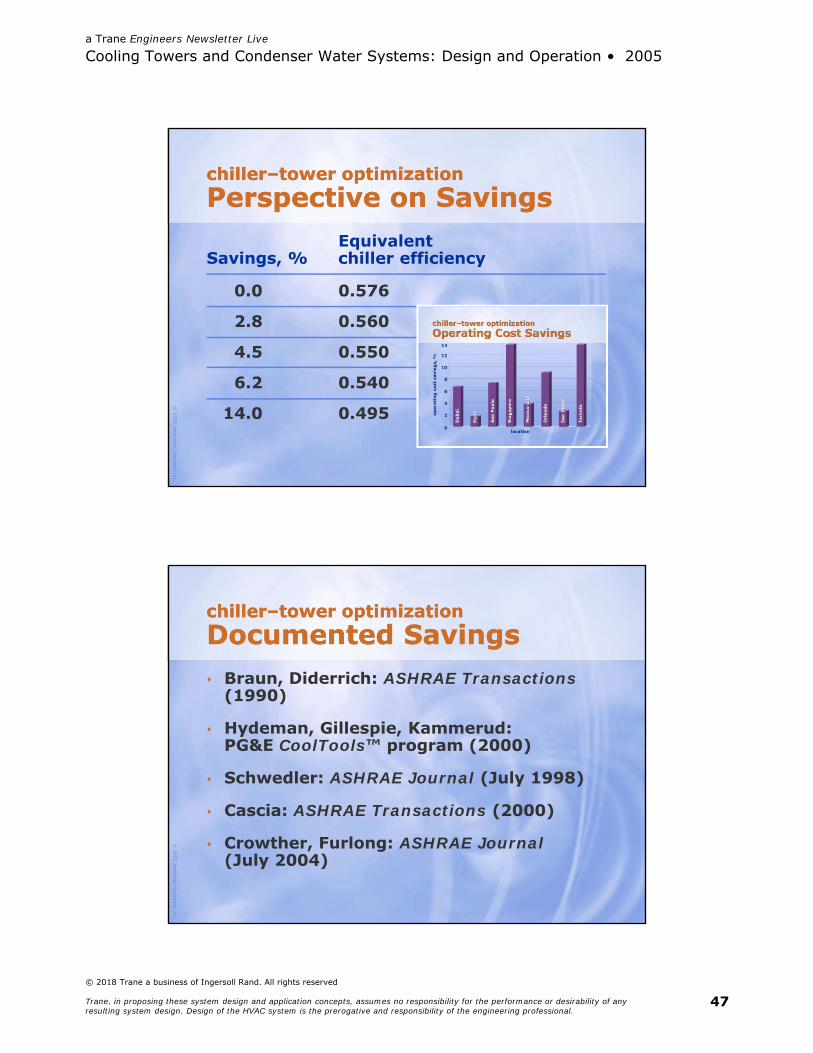
chiller–tower optimizationPerspective on Savingschiller–tower optimizationPerspective on Savings
EquivalentSavings, % chiller efficiency
0.0 0.576
2.8 0.560
4.5 0.550
6.2 0.540
14.0 0.495
© 2005
Am
erican Standard Inc.
chiller–tower optimizationDocumented Savingschiller–tower optimizationDocumented Savings Braun, Diderrich: ASHRAE Transactions
(1990)
Hydeman, Gillespie, Kammerud:PG&E CoolTools™ program (2000)
Schwedler: ASHRAE Journal (July 1998)
Cascia: ASHRAE Transactions (2000)
Crowther, Furlong: ASHRAE Journal(July 2004)
a Trane Engineers Newsletter Live
Cooling Towers and Condenser Water Systems: Design and Operation • 2005
© 2018 Trane a business of Ingersoll Rand. All rights reserved
Trane, in proposing these system design and application concepts, assumes no responsibility for the performance or desirability of any resulting system design. Design of the HVAC system is the prerogative and responsibility of the engineering professional.
48
© 2005
Am
erican Standard Inc.
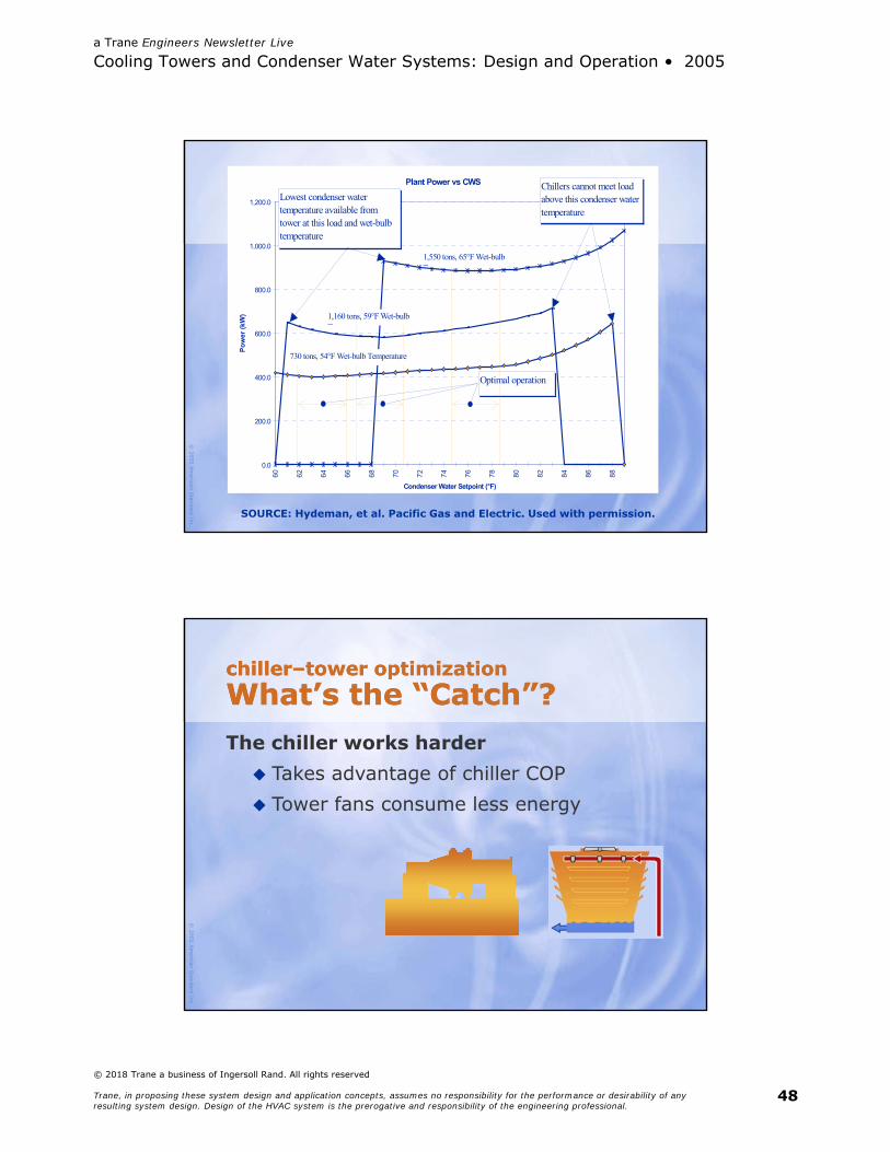
Plant Power vs CWS
0.0
200.0
400.0
600.0
800.0
1,000.0
1,200.0
60 62 64 66 68 70 72 74 76 78 80 82 84 86 88
Condenser Water Setpoint (°F)
Po
wer
(kW
)
Lowest condenser water temperature available from tower at this load and wet-bulb temperature
Chillers cannot meet load above this condenser water temperature
Optimal operation
1,550 tons, 65°F Wet-bulb T t
1,160 tons, 59°F Wet-bulb T t
730 tons, 54°F Wet-bulb Temperature
SOURCE: Hydeman, et al. Pacific Gas and Electric. Used with permission.
© 2005
Am
erican Standard Inc.
chiller–tower optimizationWhat’s the “Catch”?chiller–tower optimizationWhat’s the “Catch”?The chiller works harder Takes advantage of chiller COP Tower fans consume less energy
a Trane Engineers Newsletter Live
Cooling Towers and Condenser Water Systems: Design and Operation • 2005
© 2018 Trane a business of Ingersoll Rand. All rights reserved
Trane, in proposing these system design and application concepts, assumes no responsibility for the performance or desirability of any resulting system design. Design of the HVAC system is the prerogative and responsibility of the engineering professional.
49
© 2005
Am
erican Standard Inc.
Where’s the Meter?Where’s the Meter?On theBUILDING
© 2005
Am
erican Standard Inc.
2004 award forBest Sustainable Practice2004 award forBest Sustainable Practice
presented to Trane for
“Near optimalchiller–tower operation”by the Sustainable Buildings Industry Council (SBIC)
a Trane Engineers Newsletter Live
Cooling Towers and Condenser Water Systems: Design and Operation • 2005
© 2018 Trane a business of Ingersoll Rand. All rights reserved
Trane, in proposing these system design and application concepts, assumes no responsibility for the performance or desirability of any resulting system design. Design of the HVAC system is the prerogative and responsibility of the engineering professional.
50
© 2005
Am
erican Standard Inc.
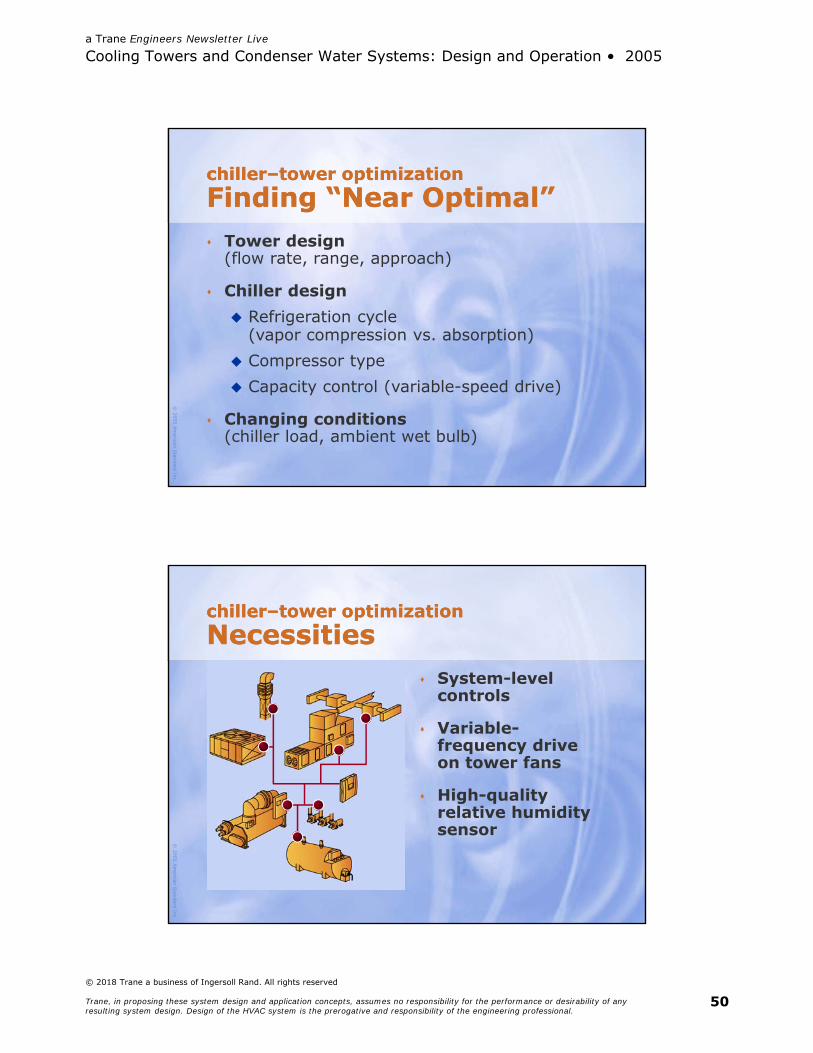
chiller–tower optimizationFinding “Near Optimal”chiller–tower optimizationFinding “Near Optimal” Tower design
(flow rate, range, approach)
Chiller design Refrigeration cycle
(vapor compression vs. absorption) Compressor type Capacity control (variable-speed drive)
Changing conditions(chiller load, ambient wet bulb)
© 2005
Am
erican Standard Inc.
chiller–tower optimizationNecessitieschiller–tower optimizationNecessities
System-level controls
Variable-frequency driveon tower fans
High-quality relative humidity sensor
a Trane Engineers Newsletter Live
Cooling Towers and Condenser Water Systems: Design and Operation • 2005
© 2018 Trane a business of Ingersoll Rand. All rights reserved
Trane, in proposing these system design and application concepts, assumes no responsibility for the performance or desirability of any resulting system design. Design of the HVAC system is the prerogative and responsibility of the engineering professional.
51
© 2005
Am
erican Standard Inc.
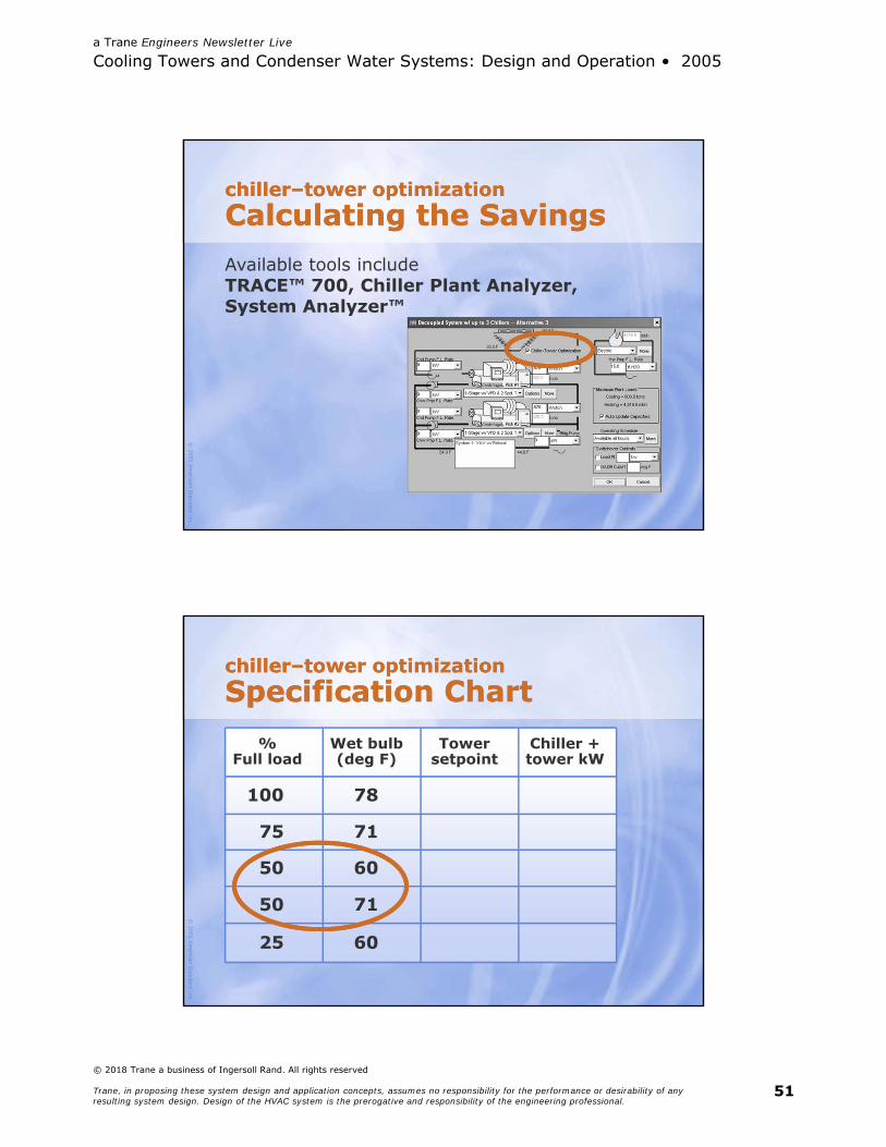
chiller–tower optimizationCalculating the Savingschiller–tower optimizationCalculating the SavingsAvailable tools includeTRACE™ 700, Chiller Plant Analyzer,System Analyzer™
© 2005
Am
erican Standard Inc.
chiller–tower optimizationSpecification Chartchiller–tower optimizationSpecification Chart
%Full load
Wet bulb(deg F)
Towersetpoint
Chiller +tower kW
100
75
50
50
25
78
71
60
71
60
a Trane Engineers Newsletter Live
Cooling Towers and Condenser Water Systems: Design and Operation • 2005
© 2018 Trane a business of Ingersoll Rand. All rights reserved
Trane, in proposing these system design and application concepts, assumes no responsibility for the performance or desirability of any resulting system design. Design of the HVAC system is the prerogative and responsibility of the engineering professional.
52
© 2005
Am
erican Standard Inc.
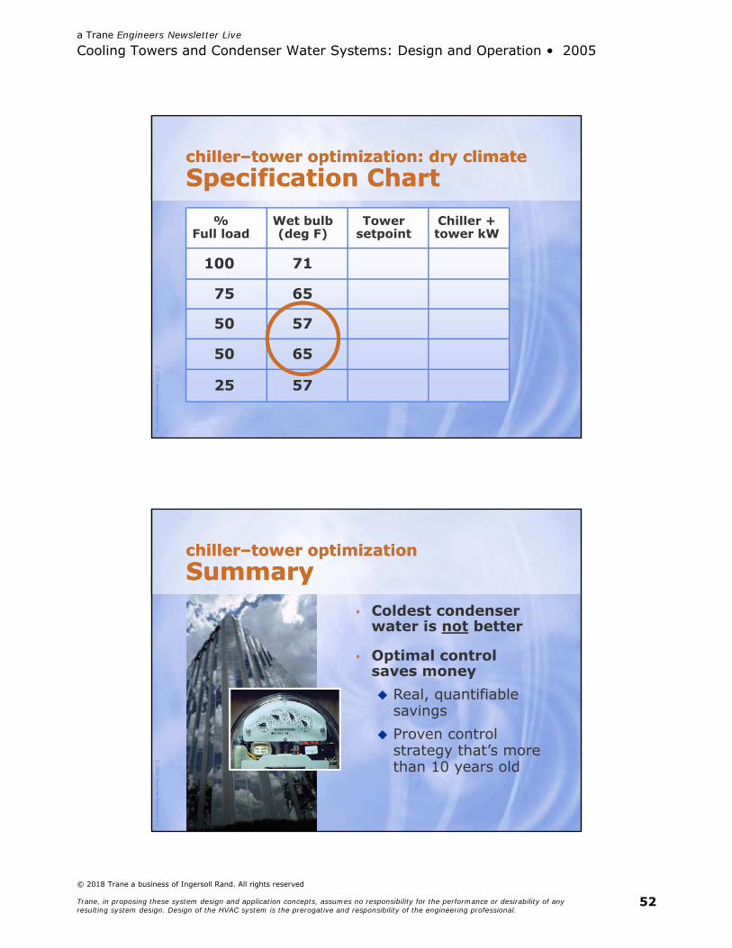
chiller–tower optimization: dry climateSpecification Chartchiller–tower optimization: dry climateSpecification Chart
%Full load
Wet bulb(deg F)
Towersetpoint
Chiller +tower kW
100
75
50
50
25
71
65
57
65
57
© 2005
Am
erican Standard Inc.
chiller–tower optimizationSummarychiller–tower optimizationSummary
Coldest condenser water is not better
Optimal control saves money Real, quantifiable
savings Proven control
strategy that’s more than 10 years old

a Trane Engineers Newsletter Live
Cooling Towers and Condenser Water Systems: Design and Operation • 2005
© 2018 Trane a business of Ingersoll Rand. All rights reserved
Trane, in proposing these system design and application concepts, assumes no responsibility for the performance or desirability of any resulting system design. Design of the HVAC system is the prerogative and responsibility of the engineering professional.
53
© 2005
Am
erican Standard Inc.
condenser water flowVariable-Speed Pump?condenser water flowVariable-Speed Pump?
Tower static lift Proper water distribution
throughout tower fill (nozzles)
Required flow through condenser
Limiting factors:
© 2005
Am
erican Standard Inc.
condenser water flowVariable-Speed Pump?condenser water flowVariable-Speed Pump?
Increases chiller power (warmer water leaving condenser)
Alters heat-transfer effectiveness of tower
Reduced speed/flow:
a Trane Engineers Newsletter Live
Cooling Towers and Condenser Water Systems: Design and Operation • 2005
© 2018 Trane a business of Ingersoll Rand. All rights reserved
Trane, in proposing these system design and application concepts, assumes no responsibility for the performance or desirability of any resulting system design. Design of the HVAC system is the prerogative and responsibility of the engineering professional.
54
© 2005
Am
erican Standard Inc.
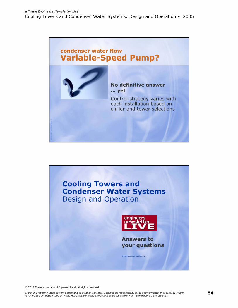
condenser water flowVariable-Speed Pump?condenser water flowVariable-Speed Pump?
Control strategy varies with each installation based on chiller and tower selections
No definitive answer… yet
© 2005 American Standard Inc.
Cooling Towers and Condenser Water SystemsDesign and Operation
Answers toyour questions
a Trane Engineers Newsletter Live
Cooling Towers and Condenser Water Systems: Design and Operation • 2005
© 2018 Trane a business of Ingersoll Rand. All rights reserved
Trane, in proposing these system design and application concepts, assumes no responsibility for the performance or desirability of any resulting system design. Design of the HVAC system is the prerogative and responsibility of the engineering professional.
55
© 2005
Am
erican Standard Inc.
SummarySummary Tower fundamentals Larger range (lower flow rate) reduces
tower size or approach Approach increases as ambient wet bulb
decreases
Reduce flow rates Lowers capital and operating costs Benefits the environment
© 2005
Am
erican Standard Inc.
SummarySummary Cooling-tower control options Invest in VFDs on all tower fans Head pressure control is critical
to reliability
Chiller–tower optimization Minimize system energy consumption Offers significant operating-cost savings
a Trane Engineers Newsletter Live
Cooling Towers and Condenser Water Systems: Design and Operation • 2005
© 2018 Trane a business of Ingersoll Rand. All rights reserved
Trane, in proposing these system design and application concepts, assumes no responsibility for the performance or desirability of any resulting system design. Design of the HVAC system is the prerogative and responsibility of the engineering professional.
56
© 2005
Am
erican Standard Inc.
references for this broadcastWhere to Learn Morereferences for this broadcastWhere to Learn More 2000 ASHRAE Handbook–Systems &
Equipment (Chapter 36)
Marley Cooling Technologies web sitehttp://www.marleyct.com/publications.asp
Cooling Technology Institute’sCTI Standard STD-201-96
Bibliography
© 2005
Am
erican Standard Inc.
Upcoming BroadcastsUpcoming Broadcasts May 25 Energy analysis–
LEED™ modeling
Sep 21 ASHRAE Std 62.1-2004 ventilation requirements
Nov 16 Demand-controlledventilation based on CO2