Embed Size (px)
Citation preview
Cooling Options for Rack Equipment with Side-to-Side Airflow
White Paper #50
By Neil Rasmussen
2004 American Power Conversion. All rights reserved. No part of this publication may be used, reproduced, photocopied, transmitted, or stored in any retrieval system of any nature, without the written permission of the copyright owner. www.apc.com Rev 2004-0
2
Executive Summary Equipment with side-to-side airflow presents special cooling challenges in today’s data
center. Common rack enclosures and rack layouts are fundamentally incompatible with
side-to-side cooling, resulting in excessive temperatures and ultimately reduced equipment
reliability. This paper describes these challenges along with several side effects that are
generally not appreciated. Various cooling options are described along with their relative
costs and benefits.
2004 American Power Conversion. All rights reserved. No part of this publication may be used, reproduced, photocopied, transmitted, or stored in any retrieval system of any nature, without the written permission of the copyright owner. www.apc.com Rev 2004-0
3
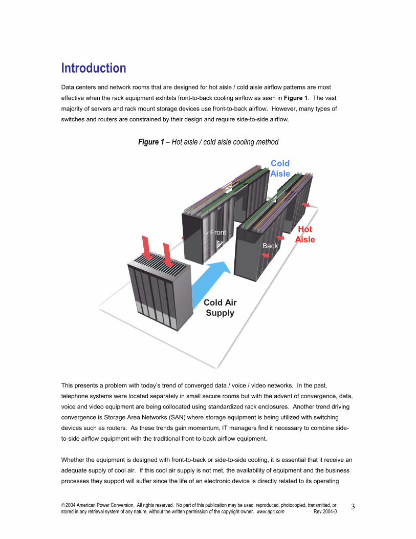
Introduction Data centers and network rooms that are designed for hot aisle / cold aisle airflow patterns are most
effective when the rack equipment exhibits front-to-back cooling airflow as seen in Figure 1. The vast
majority of servers and rack mount storage devices use front-to-back airflow. However, many types of
switches and routers are constrained by their design and require side-to-side airflow.
Figure 1 – Hot aisle / cold aisle cooling method
Cold AirSupply
ColdAisle
HotAisle
Front
Back
This presents a problem with today’s trend of converged data / voice / video networks. In the past,
telephone systems were located separately in small secure rooms but with the advent of convergence, data,
voice and video equipment are being collocated using standardized rack enclosures. Another trend driving
convergence is Storage Area Networks (SAN) where storage equipment is being utilized with switching
devices such as routers. As these trends gain momentum, IT managers find it necessary to combine side-
to-side airflow equipment with the traditional front-to-back airflow equipment.
Whether the equipment is designed with front-to-back or side-to-side cooling, it is essential that it receive an
adequate supply of cool air. If this cool air supply is not met, the availability of equipment and the business
processes they support will suffer since the life of an electronic device is directly related to its operating
2004 American Power Conversion. All rights reserved. No part of this publication may be used, reproduced, photocopied, transmitted, or stored in any retrieval system of any nature, without the written permission of the copyright owner. www.apc.com Rev 2004-0
4
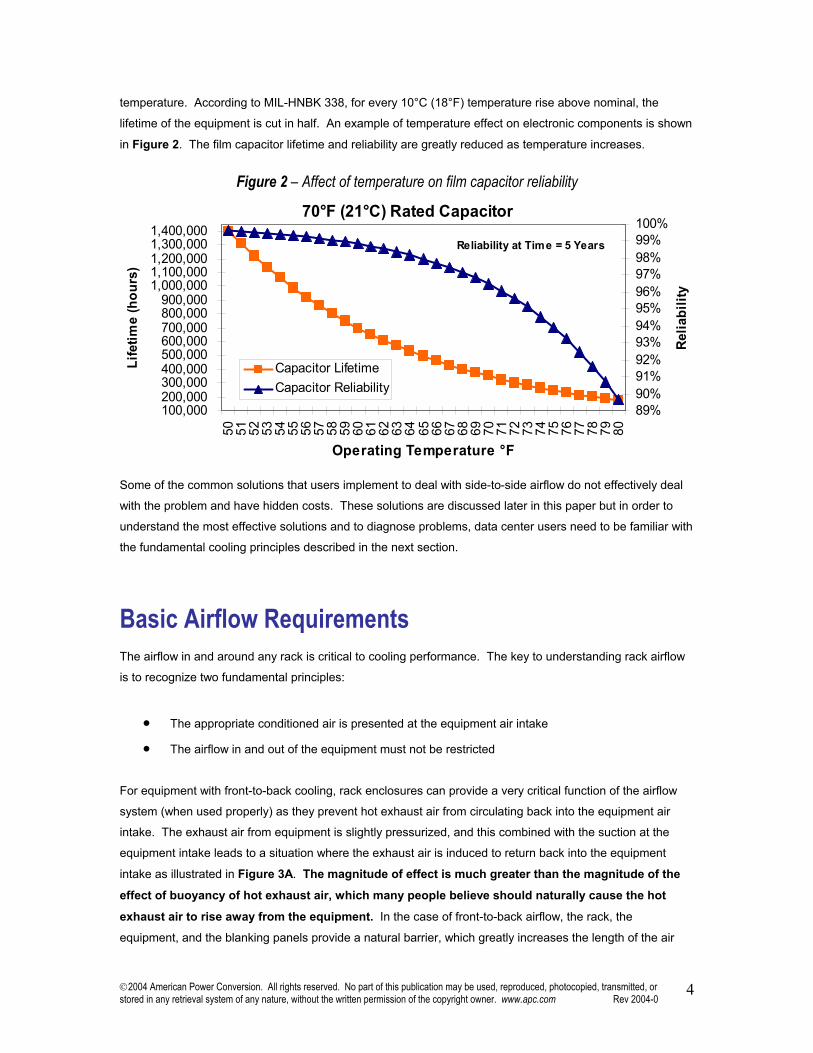
temperature. According to MIL-HNBK 338, for every 10°C (18°F) temperature rise above nominal, the
lifetime of the equipment is cut in half. An example of temperature effect on electronic components is shown
in Figure 2. The film capacitor lifetime and reliability are greatly reduced as temperature increases.
Figure 2 – Affect of temperature on film capacitor reliability
Some of the common solutions that users implement to deal with side-to-side airflow do not effectively deal
with the problem and have hidden costs. These solutions are discussed later in this paper but in order to
understand the most effective solutions and to diagnose problems, data center users need to be familiar with
the fundamental cooling principles described in the next section.
Basic Airflow Requirements The airflow in and around any rack is critical to cooling performance. The key to understanding rack airflow
is to recognize two fundamental principles:
• The appropriate conditioned air is presented at the equipment air intake
• The airflow in and out of the equipment must not be restricted
For equipment with front-to-back cooling, rack enclosures can provide a very critical function of the airflow
system (when used properly) as they prevent hot exhaust air from circulating back into the equipment air
intake. The exhaust air from equipment is slightly pressurized, and this combined with the suction at the
equipment intake leads to a situation where the exhaust air is induced to return back into the equipment
intake as illustrated in Figure 3A. The magnitude of effect is much greater than the magnitude of the
effect of buoyancy of hot exhaust air, which many people believe should naturally cause the hot
exhaust air to rise away from the equipment. In the case of front-to-back airflow, the rack, the
equipment, and the blanking panels provide a natural barrier, which greatly increases the length of the air
70°F (21°C) Rated Capacitor
100,000200,000300,000400,000500,000600,000700,000800,000900,000
1,000,0001,100,0001,200,0001,300,0001,400,000
50 51 52 53 54 55 56 57 58 59 60 61 62 63 64 65 66 67 68 69 70 71 72 73 74 75 76 77 78 79 80
Operating Temperature °F
Life
time
(hou
rs)
89%90%91%92%93%94%95%96%97%98%99%100%
Relia
bilit
y
Capacitor LifetimeCapacitor Reliability
Reliability at Time = 5 Years
2004 American Power Conversion. All rights reserved. No part of this publication may be used, reproduced, photocopied, transmitted, or stored in any retrieval system of any nature, without the written permission of the copyright owner. www.apc.com Rev 2004-0
5
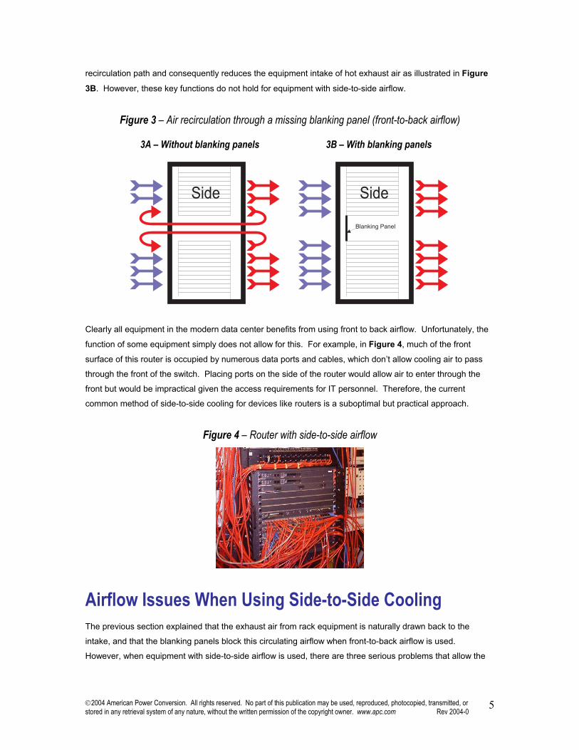
recirculation path and consequently reduces the equipment intake of hot exhaust air as illustrated in Figure
3B. However, these key functions do not hold for equipment with side-to-side airflow.
Figure 3 – Air recirculation through a missing blanking panel (front-to-back airflow)
3A – Without blanking panels 3B – With blanking panels
Clearly all equipment in the modern data center benefits from using front to back airflow. Unfortunately, the
function of some equipment simply does not allow for this. For example, in Figure 4, much of the front
surface of this router is occupied by numerous data ports and cables, which don’t allow cooling air to pass
through the front of the switch. Placing ports on the side of the router would allow air to enter through the
front but would be impractical given the access requirements for IT personnel. Therefore, the current
common method of side-to-side cooling for devices like routers is a suboptimal but practical approach.
Figure 4 – Router with side-to-side airflow
Airflow Issues When Using Side-to-Side Cooling The previous section explained that the exhaust air from rack equipment is naturally drawn back to the
intake, and that the blanking panels block this circulating airflow when front-to-back airflow is used.
However, when equipment with side-to-side airflow is used, there are three serious problems that allow the
2004 American Power Conversion. All rights reserved. No part of this publication may be used, reproduced, photocopied, transmitted, or stored in any retrieval system of any nature, without the written permission of the copyright owner. www.apc.com Rev 2004-0
6
hot exhaust air from the equipment to return to the intake and cause an associated elevation of the
equipment air intake temperature. This includes:
1) Adjacent equipment
2) No partition to separate intake from exhaust air
3) Mounting in an enclosure
These problems are magnified as the power density in the rack or enclosure (the total power being
consumed by all the equipment in each rack) increases.
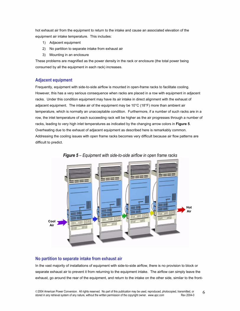
Adjacent equipment Frequently, equipment with side-to-side airflow is mounted in open-frame racks to facilitate cooling.
However, this has a very serious consequence when racks are placed in a row with equipment in adjacent
racks. Under this condition equipment may have its air intake in direct alignment with the exhaust of
adjacent equipment. The intake air of the equipment may be 10°C (18°F) more than ambient air
temperature, which is normally an unacceptable condition. Furthermore, if a number of such racks are in a
row, the inlet temperature of each succeeding rack will be higher as the air progresses through a number of
racks, leading to very high inlet temperatures as indicated by the changing arrow colors in Figure 5.
Overheating due to the exhaust of adjacent equipment as described here is remarkably common.
Addressing the cooling issues with open frame racks becomes very difficult because air flow patterns are
difficult to predict.
Figure 5 – Equipment with side-to-side airflow in open frame racks
CoolAir
HotAir
No partition to separate intake from exhaust air In the vast majority of installations of equipment with side-to-side airflow, there is no provision to block or
separate exhaust air to prevent it from returning to the equipment intake. The airflow can simply leave the
exhaust, go around the rear of the equipment, and return to the intake on the other side, similar to the front-
2004 American Power Conversion. All rights reserved. No part of this publication may be used, reproduced, photocopied, transmitted, or stored in any retrieval system of any nature, without the written permission of the copyright owner. www.apc.com Rev 2004-0
7
to-back cooled equipment in Figure 3A. Furthermore, equipment with side-to-side airflow is spaced out
vertically within a rack in most cases. This means the exhaust air has the additional possibility of going
above or below the equipment and returning to the intake on the other side; this path is typically shorter than
the path around the back of the equipment. In any case when exhaust air returns and mixes with fresh
supply air, the intake temperature of the equipment experiences an undesirable increase.
Mounting in an enclosure It is often desirable to mount equipment that uses side-to-side airflow into an enclosure as discussed in the
introduction. However, unlike the case of front-to-back airflow, where the presence of the rack enclosure
enhances cooling, in the case of side-to-side cooling the enclosure has a detrimental effect on cooling. The
side of the enclosure presents a slight additional resistance barrier to incoming fresh cool air, and also a
slight barrier to outgoing hot exhaust air. When this additional resistance is combined with the existing
tendency for exhaust air to return to the equipment intake, the effect is dramatic. A substantial part of the
exhaust air returns to the intake. This situation is even worse if adjacent equipment is placed in bayed rows
of racks without an air barrier between the racks. The use of a rack enclosure with equipment that uses
side-to-side airflow significantly amplifies the deleterious effects described in the previous sections.
Nevertheless, there are a variety of very effective ways to utilize enclosures with equipment with side-to-side
airflow; these are described later in this paper.
The desire to eliminate overheating causes users to implement various changes to reduce the temperature
of equipment with side-to-side airflow. Although reducing equipment temperature may be achieved, the
conventional solutions often have other hidden costs. Some methods that lower equipment temperature
cause the cooling system to operate inefficiently and can defeat cooling redundancy. To understand these
costs it is important to consider what drives cooling costs.
Factors Influencing Cooling Costs The cost of cooling is a significant cost. For many installations the electricity consumed by the cooling
system is nearly half of the electricity consumed by the data center. The operating cost of electricity for the
cooling system alone is often a larger contributor to Total Cost of Ownership than the entire capital outlay for
power and cooling systems. Therefore, it is prudent to prevent energy waste in the cooling system.
The amount of cooling Wattage or Tonnage of cooling capacity required by a data center is not affected by
recirculation; however the efficiency of the cooling systems is significantly and adversely affected. The
reason is that a system with significant recirculation has the following characteristics:
A) It requires lower temperature CRAC supply air to make up for the mixing of hotter exhaust air
B) It returns cooler air to the CRAC unit due to mixing of cool air into the hot exhaust air
C) Cooler CRAC air return temperature results in dehumidification which must be compensated for by
supplemental humidification
2004 American Power Conversion. All rights reserved. No part of this publication may be used, reproduced, photocopied, transmitted, or stored in any retrieval system of any nature, without the written permission of the copyright owner. www.apc.com Rev 2004-0
8
Recirculation and its related hot-spots can cause an increase of over 10% in CRAC electricity costs and
require additional CRAC units to be installed along with their capital and operating costs. Furthermore,
expectations regarding the ability of the system to operate with one CRAC unit down for maintenance may
not be met. These issues are discussed in additional detail in APC White Paper #49, “Avoidable Mistakes
that Compromise Cooling Performance in Data Centers and Network Rooms”.
Effective Cooling Methods for Side-to-Side Airflow A variety of methods can be used to cool systems with side-to-side airflow. These methods are described in
this section, along with their key attributes. The alternatives are summarized and contrasted in Table 1 at
the end of this section which will aid in the selection of the appropriate method.
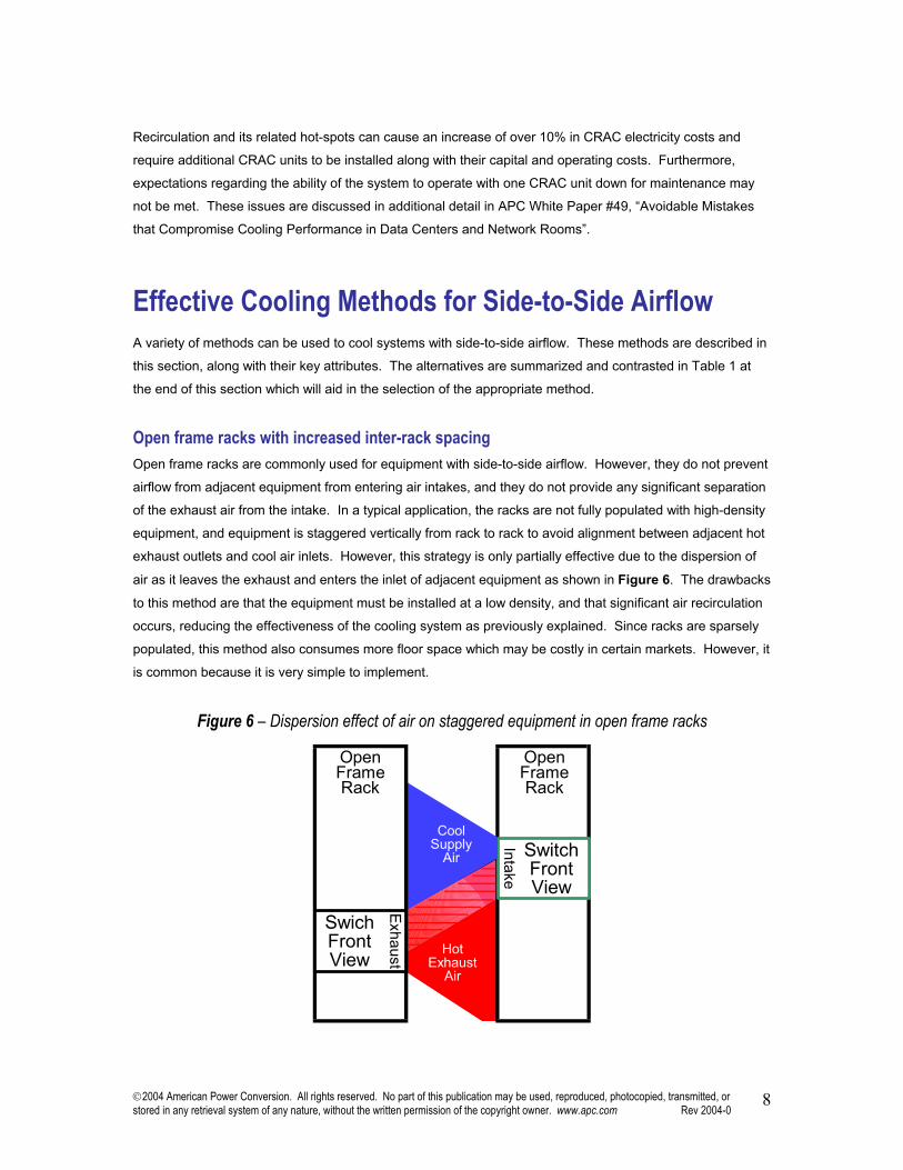
Open frame racks with increased inter-rack spacing Open frame racks are commonly used for equipment with side-to-side airflow. However, they do not prevent
airflow from adjacent equipment from entering air intakes, and they do not provide any significant separation
of the exhaust air from the intake. In a typical application, the racks are not fully populated with high-density
equipment, and equipment is staggered vertically from rack to rack to avoid alignment between adjacent hot
exhaust outlets and cool air inlets. However, this strategy is only partially effective due to the dispersion of
air as it leaves the exhaust and enters the inlet of adjacent equipment as shown in Figure 6. The drawbacks
to this method are that the equipment must be installed at a low density, and that significant air recirculation
occurs, reducing the effectiveness of the cooling system as previously explained. Since racks are sparsely
populated, this method also consumes more floor space which may be costly in certain markets. However, it
is common because it is very simple to implement.
Figure 6 – Dispersion effect of air on staggered equipment in open frame racks
SwitchFrontView
HotExhaust
Air
OpenFrameRack
Intake
CoolSupply
Air
SwichFrontView
OpenFrameRack
Exhaust
2004 American Power Conversion. All rights reserved. No part of this publication may be used, reproduced, photocopied, transmitted, or stored in any retrieval system of any nature, without the written permission of the copyright owner. www.apc.com Rev 2004-0
9
Low density enclosure Like the open frame racks, equipment with side-to-side airflow placed in full enclosures does not fill the
enclosure to full physical capacity, due to powering or cooling limitations. Typically the equipment is spaced
out vertically in a rack and no blanking panels are installed in the unused “U” space. This arrangement
effectively reduces the rack power density and consequently reduces the likelihood of hotspots. However,
enclosures still encourage recirculation which will be expected to some degree using this method. This
method is not recommended in markets where real estate is at a premium since reducing the rack power
density distributes the heat load across a larger floor area.
Supplemental fans Supplemental fans are added as a typical response to overheating. These fans may be rack mounted in
open frame racks or enclosures, but it is not uncommon to see free-standing fans in use. The idea here is to
simply blow or suck the hot air away from the hot equipment.
The fans essentially work by operating as a mixer, mixing the equipment exhaust air and the CRAC supply
air to create an air temperature that is hotter than the CRAC supply, but cooler than the equipment exhaust.
The fans also act to increase the flow of air through the equipment. While a fan typically does decrease the
equipment operating temperature and local hot spots, the cost is significant. The CRAC system efficiency is
decreased due to the lower CRAC return air temperature, leading to the consequences described earlier
including: increased dehumidification / humidification, lower CRAC capacity, and possible loss of
redundancy.
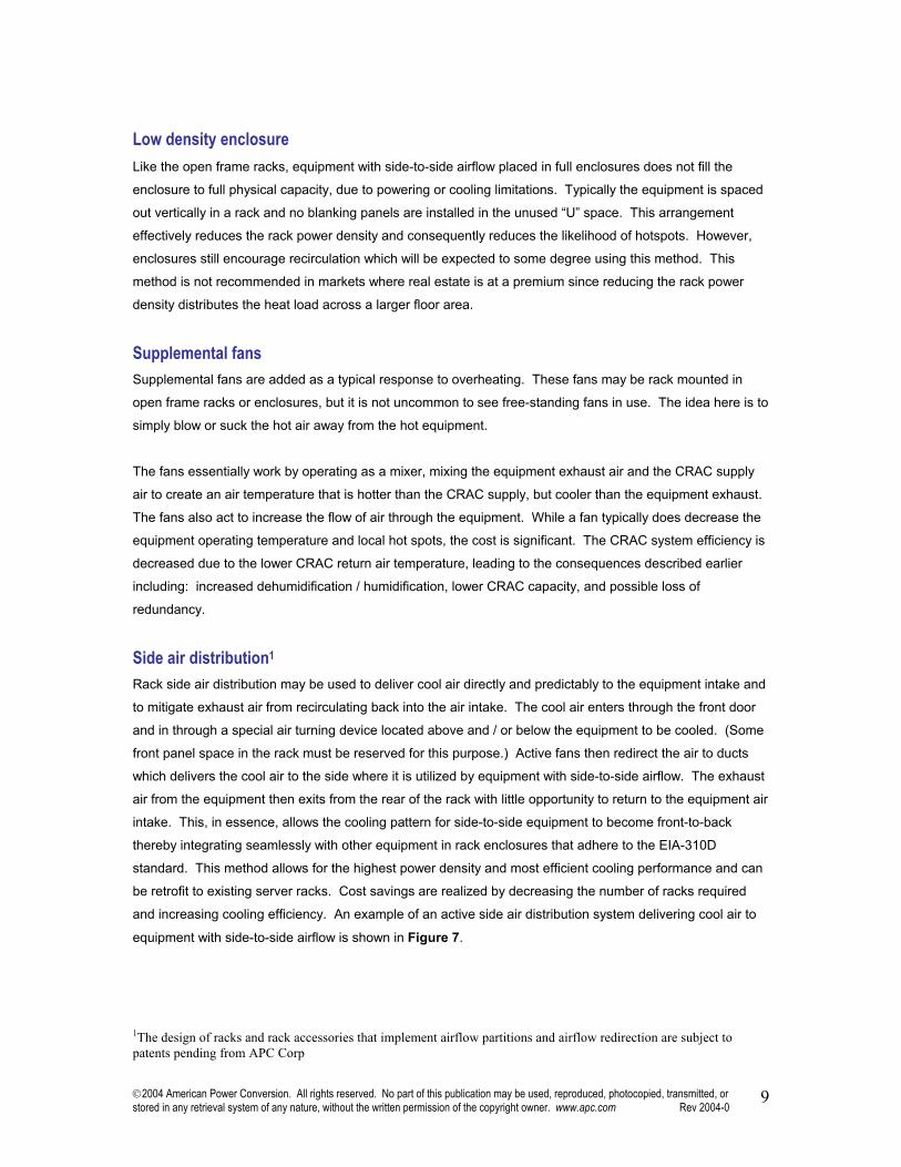
Side air distribution1 Rack side air distribution may be used to deliver cool air directly and predictably to the equipment intake and
to mitigate exhaust air from recirculating back into the air intake. The cool air enters through the front door
and in through a special air turning device located above and / or below the equipment to be cooled. (Some
front panel space in the rack must be reserved for this purpose.) Active fans then redirect the air to ducts
which delivers the cool air to the side where it is utilized by equipment with side-to-side airflow. The exhaust
air from the equipment then exits from the rear of the rack with little opportunity to return to the equipment air
intake. This, in essence, allows the cooling pattern for side-to-side equipment to become front-to-back
thereby integrating seamlessly with other equipment in rack enclosures that adhere to the EIA-310D
standard. This method allows for the highest power density and most efficient cooling performance and can
be retrofit to existing server racks. Cost savings are realized by decreasing the number of racks required
and increasing cooling efficiency. An example of an active side air distribution system delivering cool air to
equipment with side-to-side airflow is shown in Figure 7.
1The design of racks and rack accessories that implement airflow partitions and airflow redirection are subject to patents pending from APC Corp
2004 American Power Conversion. All rights reserved. No part of this publication may be used, reproduced, photocopied, transmitted, or stored in any retrieval system of any nature, without the written permission of the copyright owner. www.apc.com Rev 2004-0
10
Figure 7 – Top-front view perspective of side-to-side airflow supported in a single rack using an side-to-side airflow
Side air distribution allows rack enclosures to be placed side-to-side and still maintain proper airflow thereby
consuming less floor space. However, it is imperative that the temperature of air diverted to the equipment
with side-to-side airflow be in accordance with ANSI2 and ASHREA3 standards for cooling electronic
equipment.
To ensure that this method of cooling is effective, a study of steady state measurements was conducted.
The test enclosure consisted of an APC NetShelter VX, 42U enclosure. The rack mounted equipment
consisted of a Cisco 6500 Series switch in the center and multiple 1U heat loads above and below the switch
to simulate the heat load of additional equipment. The temperature was then measured at the inlet of the
Cisco switch for various heat loads. The measurements were run with and without the assistance of the side
Hot Air Exhaust
Cool Air Inlet
2004 American Power Conversion. All rights reserved. No part of this publication may be used, reproduced, photocopied, transmitted, or stored in any retrieval system of any nature, without the written permission of the copyright owner. www.apc.com Rev 2004-0
11
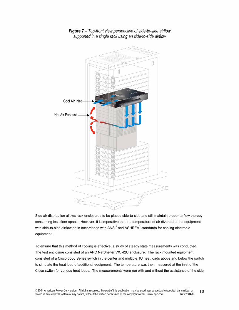
air distribution device and resulted in an average difference of 15°F (8.3°C) between both tests. The results
of this test are illustrated in Figure 8.
Figure 8 – Equipment inlet temperature vs. rack load
2ANSI (American National Standards Institute) standard T1.304-1997 states that acceptable operating conditions for telecom equipment are between 41 and 104°F (5 and 40°C). 3ASHRAE (American Society of Heating, Refrigeration, and Air-Conditioning Engineers) TC9 recommends inlet temperatures for electronic equipment be between 68 and 77°F (20 and 25°C)
110
105
100
95
90
85
80
75
70
77
104
Side
-to-S
ide E
quip
men
t Inl
et T
emp
- °F
Side
-to-S
ide E
quip
men
t Inl
et T
emp
- °C
43
41
38
35
32
29
27
24
21
25
40+Unacceptable ANSI Range
Inlet Temperature of High End RouterWithout Rack Side Air Distribution Unit
Inlet Temperature of High End RouterWith Rack Side Air Distribution Unit
+ANSI Design Standards
^ASHRAE Recommended Range
Total Rack Load - kW*All Tests Performed in an APC Netshelter VX Enclosure+ANSI – American National Standards Institute^ASHRAE – American Society of Heating, Refrigeration, & Air-Conditioning Engineers
1.0 2.0 3.0 4.0 5.0 6.0
2004 American Power Conversion. All rights reserved. No part of this publication may be used, reproduced, photocopied, transmitted, or stored in any retrieval system of any nature, without the written permission of the copyright owner. www.apc.com Rev 2004-0
12
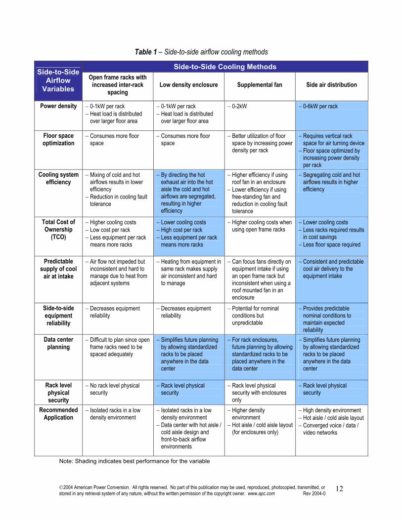
Table 1 – Side-to-side airflow cooling methods
Side-to-Side Cooling Methods Side-to-Side
Airflow Variables
Open frame racks with increased inter-rack
spacing Low density enclosure Supplemental fan Side air distribution
Power density − 0-1kW per rack − Heat load is distributed
over larger floor area
− 0-1kW per rack − Heat load is distributed
over larger floor area
− 0-2kW − 0-6kW per rack
Floor space optimization
− Consumes more floor space
− Consumes more floor space
− Better utilization of floor space by increasing power density per rack
− Requires vertical rack space for air turning device
− Floor space optimized by increasing power density per rack
Cooling system efficiency
− Mixing of cold and hot airflows results in lower efficiency
− Reduction in cooling fault tolerance
− By directing the hot exhaust air into the hot aisle the cold and hot airflows are segregated, resulting in higher efficiency
− Higher efficiency if using roof fan in an enclosure
− Lower efficiency if using free-standing fan and reduction in cooling fault tolerance
− Segregating cold and hot airflows results in higher efficiency
Total Cost of Ownership
(TCO)
− Higher cooling costs − Low cost per rack − Less equipment per rack
means more racks
− Lower cooling costs − High cost per rack − Less equipment per rack
means more racks
− Higher cooling costs when using open frame racks
− Lower cooling costs − Less racks required results
in cost savings − Less floor space required
Predictable supply of cool
air at intake
− Air flow not impeded but inconsistent and hard to manage due to heat from adjacent systems
− Heating from equipment in same rack makes supply air inconsistent and hard to manage
− Can focus fans directly on equipment intake if using an open frame rack but inconsistent when using a roof mounted fan in an enclosure
− Consistent and predictable cool air delivery to the equipment intake
Side-to-side equipment reliability
− Decreases equipment reliability
− Decreases equipment reliability
− Potential for nominal conditions but unpredictable
− Provides predictable nominal conditions to maintain expected reliability
Data center planning
− Difficult to plan since open frame racks need to be spaced adequately
− Simplifies future planning by allowing standardized racks to be placed anywhere in the data center
− For rack enclosures, future planning by allowing standardized racks to be placed anywhere in the data center
− Simplifies future planning by allowing standardized racks to be placed anywhere in the data center
Rack level physical security
− No rack level physical security
− Rack level physical security
− Rack level physical security with enclosures only
− Rack level physical security
Recommended Application
− Isolated racks in a low density environment
− Isolated racks in a low density environment
− Data center with hot aisle / cold aisle design and front-to-back airflow environments
− Higher density environment
− Hot aisle / cold aisle layout (for enclosures only)
− High density environment − Hot aisle / cold aisle layout − Converged voice / data /
video networks
Note: Shading indicates best performance for the variable
2004 American Power Conversion. All rights reserved. No part of this publication may be used, reproduced, photocopied, transmitted, or stored in any retrieval system of any nature, without the written permission of the copyright owner. www.apc.com Rev 2004-0
13
Restrictions placed on Side-to-Side Airflow Equipment Equipment vendors frequently publish installation and environmental guidelines for their products. In the
case of equipment with side-to-side airflow, these guidelines become restrictive given the propensity for
deficient cooling as power densities increase. Like most IT equipment, the electronics in side-to-side airflow
equipment monitor internal temperature. If the operating inlet temperature rises above the maximum
recommended temperature (typically 104°F [40°C]) the equipment may shut down to prevent damage,
thereby causing critical system downtime.
Guidelines specific to cooling were gathered from various switch and router vendors and are listed below:
• Have a minimum air space of 6 inches between walls and the chassis air vents.
• Have a minimum horizontal separation of 12 inches between two chassis is required.
• Avoid placing the chassis in an overly congested rack.
• Do not place equipment near the bottom of the rack, because it might generate excessive heat that is
drawn upward and into the intake ports of the equipment above, leading to over temperature conditions
in the chassis at the top or near the top of the rack.
• Never install the chassis in an enclosed rack that is not properly ventilated or air-conditioned.
• Install the chassis in an enclosed rack only if it has adequate ventilation or an exhaust fan; use an open
rack whenever possible.
• Use baffles inside the enclosed rack to assist in cooling the chassis.
• Planning the proper location and layout of your equipment rack is essential for successful system
operation.
• Unit is intended for installation in restricted access areas. A restricted access area can be special tool,
lock and key or other means of security.
These restrictions leave the IT manager with limited flexibility when planning their data center layout. With
the advent of viable rack enclosed solutions for equipment with side-to-side airflow, IT managers can more
easily adapt to constant changes in today’s data center. In particular, side air distribution allows for higher
rack power densities as well as improved and predicable cooling efficiency. Furthermore, the side air
distribution method facilitates the convergence of data and voice networks into a common hot aisle / cold
aisle environment. Although not mentioned in the guidelines, an enclosure also provides increased physical
security thereby eliminating the need for a separate means of security.
Conclusion The cooling of rack equipment with side-to-side airflow requires special planning to avoid inefficiency and
malfunction, especially when used in front-to-back airflow data center environments. The main problem with
side-to-side cooling is that the air intake of the equipment is frequently fed with exhaust air from either itself
or adjacent equipment.
2004 American Power Conversion. All rights reserved. No part of this publication may be used, reproduced, photocopied, transmitted, or stored in any retrieval system of any nature, without the written permission of the copyright owner. www.apc.com Rev 2004-0
14
Conventional solutions such as spreading equipment out or using supplemental fans can control hot-spots
but reduce cooling system operating efficiency. In these systems, some mixing of the exhaust and intake air
occurs which prevents the equipment intake temperature from reaching the ideal lower values that are
achieved by conventional front-to-back cooling.
There is a general belief that it is not possible to use full rack enclosures in conjunction with side-to-side
airflow and that open-frame racks must be used. However, using proven methods, it is possible to cool high-
density enclosures containing equipment with side-to-side airflow in a highly efficient manner. These
methods include drawing air in from the front of a rack, redirecting it to the equipment intake on the side of
the unit, and then exhausting it from the rear of a rack. This system reduces equipment operating
temperature to safe levels and maximizes cooling system efficiency by separating hot exhaust air from intake
air. Converting side-to-side airflow into front-to-back airflow in this manner allows seamless integration into
high-density data center rack cooling systems using the widely accepted hot aisle / cold aisle design. The
value of converting such equipment lies in the predictability of equipment performance at any time in the
future without having to plan in advance where the equipment will be located. An IT manger can deploy
side-to-side airflow equipment at any time, in any location, knowing that it will integrate reliably into an
enclosure environment. The need to plan special low-density areas in the data center for equipment with
side-to-side airflow is eliminated.
About the Author: Neil Rasmussen is a founder and the Chief Technical Officer of American Power Conversion. At APC, Neil
directs the world’s largest R&D budget devoted to Power, Cooling, and Rack infrastructure for critical
networks, with principal product development centers in Massachusetts, Missouri, Denmark, Rhode Island,
Taiwan, and Ireland. Neil is currently leading the effort at APC to develop modular scalable data center
solutions.
Prior to founding APC in 1981, Neil received his Bachelors and Masters degrees from MIT in electrical
engineering where he did his thesis on the analysis of a 200MW power supply for a Tokamak Fusion reactor.
From 1979 to 1981 he worked at MIT Lincoln Laboratories on flywheel energy storage systems and solar
electric power systems.