Embed Size (px)
Citation preview
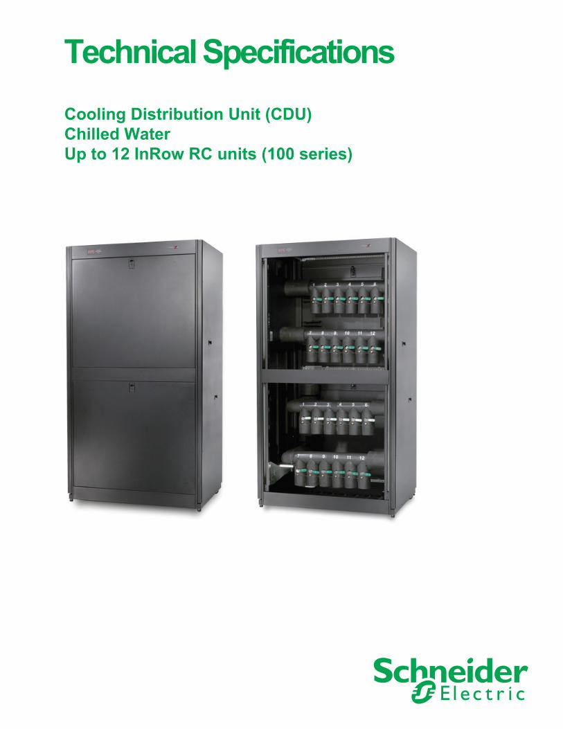
Technical Specifications Cooling Distribution Unit (CDU)Chilled WaterUp to 12 InRow RC units (100 series)
American Power Conversion Legal DisclaimerThe information presented in this manual is not warranted by the American Power Conversion Corpora-tion to be authoritative, error free, or complete. This publication is not meant to be a substitute for a detailed operational and site specific development plan. Therefore, American Power Conversion Corpora-tion assumes no liability for damages, violations of codes, improper installation, system failures, or any other problems that could arise based on the use of this Publication.
The information contained in this Publication is provided as is and has been prepared solely for the pur-pose of evaluating data center design and construction. This Publication has been compiled in good faith by American Power Conversion Corporation. However, no representation is made or warranty given, either express or implied, as to the completeness or accuracy of the information this Publication contains.
IN NO EVENT SHALL AMERICAN POWER CONVERSION CORPORATION, OR ANY PAR-ENT, AFFILIATE OR SUBSIDIARY COMPANY OF AMERICAN POWER CONVERSION CORPORATION OR THEIR RESPECTIVE OFFICERS, DIRECTORS, OR EMPLOYEES BE LIABLE FOR ANY DIRECT, INDIRECT, CONSEQUENTIAL, PUNITIVE, SPECIAL, OR INCIDENTAL DAMAGES (INCLUDING, WITHOUT LIMITATION, DAMAGES FOR LOSS OF BUSINESS, CONTRACT, REVENUE, DATA, INFORMATION, OR BUSINESS INTERRUP-TION) RESULTING FROM, ARISING OUT, OR IN CONNECTION WITH THE USE OF, OR INABILITY TO USE THIS PUBLICATION OR THE CONTENT, EVEN IF AMERICAN POWER CONVERSION CORPORATION HAS BEEN EXPRESSLY ADVISED OF THE POSSI-BILITY OF SUCH DAMAGES. AMERICAN POWER CONVERSION CORPORATION RESERVES THE RIGHT TO MAKE CHANGES OR UPDATES WITH RESPECT TO OR IN THE CONTENT OF THE PUBLICATION OR THE FORMAT THEREOF AT ANY TIME WITHOUT NOTICE.
Copyright, intellectual, and all other proprietary rights in the content (including but not limited to soft-ware, audio, video, text, and photographs) rests with American Power Conversion Corporation or its licensors. All rights in the content not expressly granted herein are reserved. No rights of any kind are licensed or assigned or shall otherwise pass to persons accessing this information.
This Publication shall not be for resale in whole or in part.
Table of Contents
Technical Data............................................................................................ 1Model Identification. . . . . . . . . . . . . . . . . . . . . . . . . . . . . . . . . . . . . . . . . . . . . . . . . .1
Model identification label location . . . . . . . . . . . . . . . . . . . . . . . . . . . . . . . . . . . . . . . . 1Model nomenclature . . . . . . . . . . . . . . . . . . . . . . . . . . . . . . . . . . . . . . . . . . . . . . . . . . . . 1
Features and Options . . . . . . . . . . . . . . . . . . . . . . . . . . . . . . . . . . . . . . . . . . . . . . . .2Capacity . . . . . . . . . . . . . . . . . . . . . . . . . . . . . . . . . . . . . . . . . . . . . . . . . . . . . . . . . . . . . . 2Cooling Distribution . . . . . . . . . . . . . . . . . . . . . . . . . . . . . . . . . . . . . . . . . . . . . . . . . . . . 2Configuration . . . . . . . . . . . . . . . . . . . . . . . . . . . . . . . . . . . . . . . . . . . . . . . . . . . . . . . . . 2Compliance Approval . . . . . . . . . . . . . . . . . . . . . . . . . . . . . . . . . . . . . . . . . . . . . . . . . . . 2Standard Components . . . . . . . . . . . . . . . . . . . . . . . . . . . . . . . . . . . . . . . . . . . . . . . . . . 3
Scalable Solution for Critical Environments. . . . . . . . . . . . . . . . . . . . . . . . . . . . . .4Overhead Piping Design . . . . . . . . . . . . . . . . . . . . . . . . . . . . . . . . . . . . . . . . . . . . . . . . 4High Density . . . . . . . . . . . . . . . . . . . . . . . . . . . . . . . . . . . . . . . . . . . . . . . . . . . . . . . . . . 4Coolant Balancing . . . . . . . . . . . . . . . . . . . . . . . . . . . . . . . . . . . . . . . . . . . . . . . . . . . . . 4Leased Facilities . . . . . . . . . . . . . . . . . . . . . . . . . . . . . . . . . . . . . . . . . . . . . . . . . . . . . . . 4APC by Schneider Electric Cooling Distribution Unit: The Right Solution . . . . . . . . 4Chilled Water Configuration . . . . . . . . . . . . . . . . . . . . . . . . . . . . . . . . . . . . . . . . . . . . . 5Cooling Distribution Unit Advantages . . . . . . . . . . . . . . . . . . . . . . . . . . . . . . . . . . . . . 5InRow Advantages . . . . . . . . . . . . . . . . . . . . . . . . . . . . . . . . . . . . . . . . . . . . . . . . . . . . . 6
Standard Features . . . . . . . . . . . . . . . . . . . . . . . . . . . . . . . . . . . . . . . . . . . . . . . . . . .7Single Skin Panels . . . . . . . . . . . . . . . . . . . . . . . . . . . . . . . . . . . . . . . . . . . . . . . . . . . . . 7Isolation and Balancing Valves . . . . . . . . . . . . . . . . . . . . . . . . . . . . . . . . . . . . . . . . . . . 7Main Supply and Return Headers . . . . . . . . . . . . . . . . . . . . . . . . . . . . . . . . . . . . . . . . . 7Multiple Distribution Supply and Return Lines . . . . . . . . . . . . . . . . . . . . . . . . . . . . . . 7Top or Bottom Distribution Piping Connections . . . . . . . . . . . . . . . . . . . . . . . . . . . . . 7Pipe Fittings . . . . . . . . . . . . . . . . . . . . . . . . . . . . . . . . . . . . . . . . . . . . . . . . . . . . . . . . . . 7Clamps/Hangers . . . . . . . . . . . . . . . . . . . . . . . . . . . . . . . . . . . . . . . . . . . . . . . . . . . . . . . 7Jointless Piping . . . . . . . . . . . . . . . . . . . . . . . . . . . . . . . . . . . . . . . . . . . . . . . . . . . . . . . 8Flexible Piping . . . . . . . . . . . . . . . . . . . . . . . . . . . . . . . . . . . . . . . . . . . . . . . . . . . . . . . . 8Pipe Insulation . . . . . . . . . . . . . . . . . . . . . . . . . . . . . . . . . . . . . . . . . . . . . . . . . . . . . . . . 8
Component Identification . . . . . . . . . . . . . . . . . . . . . . . . . . . . . . . . . . . . . . . . . . . . .9External components . . . . . . . . . . . . . . . . . . . . . . . . . . . . . . . . . . . . . . . . . . . . . . . . . . . 9Interior – piping configuration . . . . . . . . . . . . . . . . . . . . . . . . . . . . . . . . . . . . . . . . . . . 10
Performance Data . . . . . . . . . . . . . . . . . . . . . . . . . . . . . . . . . . . . . . . . . . . . . . . . . .11CDU Pressure Drop . . . . . . . . . . . . . . . . . . . . . . . . . . . . . . . . . . . . . . . . . . . . . . . . . . . 12Piping Data . . . . . . . . . . . . . . . . . . . . . . . . . . . . . . . . . . . . . . . . . . . . . . . . . . . . . . . . . . 12Calculating Pressure Drop . . . . . . . . . . . . . . . . . . . . . . . . . . . . . . . . . . . . . . . . . . . . . 13
Dimensional Data. . . . . . . . . . . . . . . . . . . . . . . . . . . . . . . . . . . . . . . . . . . . . . . . . . .14CDU Assembled Module . . . . . . . . . . . . . . . . . . . . . . . . . . . . . . . . . . . . . . . . . . . . . . . 14Piping Connection . . . . . . . . . . . . . . . . . . . . . . . . . . . . . . . . . . . . . . . . . . . . . . . . . . . . 15
990-4729-001 Cooling Distribution Unit Technical Specifications i
Warranty ................................................................................................... 17Guide Specifications ............................................................................... 19
Guide Specifications for the CDU . . . . . . . . . . . . . . . . . . . . . . . . . . . . . . . . . . . . .19
ii Cooling Distribution Unit Technical Specifications 990-4729-001
Technical Data
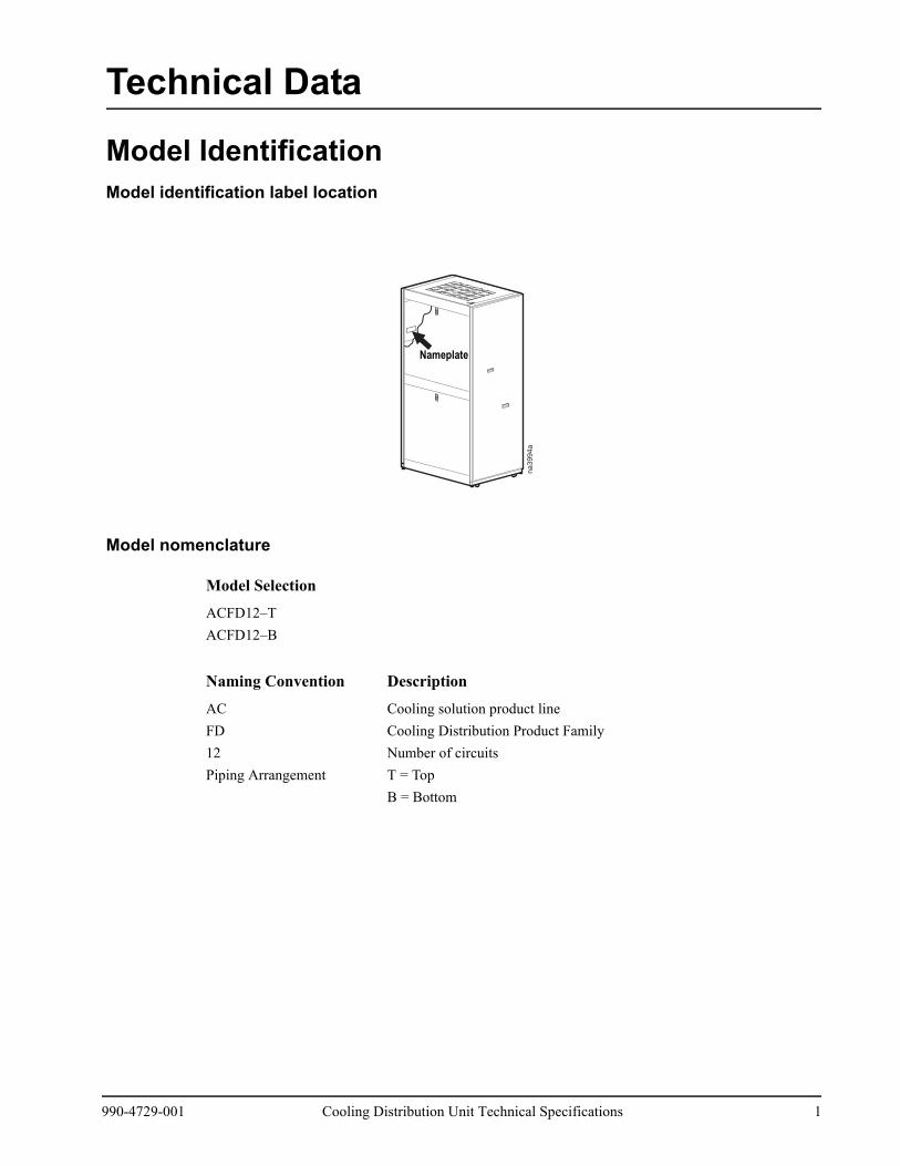
Model IdentificationModel identification label location
Model nomenclature
Model Selection
ACFD12–TACFD12–B
Naming Convention Description
AC Cooling solution product lineFD Cooling Distribution Product Family12 Number of circuitsPiping Arrangement T = Top
B = Bottom
na3994a
Nameplate
990-4729-001 Cooling Distribution Unit Technical Specifications 1
Features and OptionsThe scalable, cooling distribution unit offers efficient, effective, and economical fluid distribution for use with the InRow RC 100 series.
Precision environmental requirements now reach far beyond the confines of the traditional data center or computer room to encompass a larger suite of applications referred to as technology rooms. Critical environment applications include:
• Computer rooms• Telecommunication facilities• Clean rooms• Power Equipment• Medical equipment rooms• Archives• LAN/WAN environments
A worldwide network of APC by Schneider Electric representatives is fully qualified to provide engineering, sales, installation, and service for our products.
APC by Schneider Electric warrants all parts for 12 months from shipment. Extended warranties are available.
Capacity
The Cooling Distribution Unit or CDU is available for up to 12 InRow RC 100 series units.
Cooling Distribution
Cooling distribution systems are placed either inside or outside of the data center. Fluid is pumped into the CDU main supply header from the chiller, distributed into individual supply lines, absorbs rejected heat from the air through the CW, and is routed back to the chiller through the CDU return lines.
The CDU is manually set to ensure that fluid flow is equal to all of the InRow RC Air Conditioners. Improper fluid flow could result in hot spots within the data center.
Configuration
• Chilled Water• Glycol/Chilled Water
Compliance Approval
• UL Listed to UL 1995 and CSA C22.2 No. 236
2 Cooling Distribution Unit Technical Specifications 990-4729-001
Standard Components
• Manual Isolation and Balancing Valve• Individually controlled supply and return lines• Multiple Supply and Return Lines• Main Supply and Return Headers• Distribution Piping as Top or Bottom Configuration• Flexible and Jointless Piping• Pipe Couplings• Pipe Insulation• Pipe Clamp / Hanger• Secure Lockable Panels• Main Supply and Return (Field Configurable as Top or Bottom)• Matching Brass and Dielectric Flanges for Chilled Water Connection
990-4729-001 Cooling Distribution Unit Technical Specifications 3
Scalable Solution for Critical EnvironmentsOverhead Piping Design
Mitigating the risk of fluid leaks is critical to the smooth operation of a technology room. However, raised floors are not an option in some data center environments. This hard floor environment requires that the cooling fluid piping be installed overhead. Because traditional hard copper piping has numerous joints, the risk of leaks increases in the data center. The use of flexible piping allows the system to be routed overhead without the use of elbows or any intermediate joints from the chilled water source to each InRow RC, greatly reducing the leak and condensation potential in the pipe system. This solution reduces the concern of users and IT managers by routing chilled water piping away from their IT equipment.
High Density
In a technology room, the consolidation of servers, whether from constraints on space or from moving data on multiple clusters of servers to a single, larger server, cause high density areas.
Naturally, this will make the power densities increase, resulting in a higher than average cooling load per rack. The higher cooling demand might require additional Computer Room Air Conditioner (CRAC) units, and thus require additional fluid lines to be installed. Traditional approaches employ hard copper piping which requires an increase in labor and deployment time when infrastructure demands change.
Coolant Balancing
High density environments demand multiple CRAC units to handle the cooling load required by the IT equipment. To handle this load, multiple fluid lines need to be routed through the data center to the CRACs. Each of the fluid lines employs individual valves that are located in areas that may not be accessible from the data center.
Leased Facilities
Installing a data center in a leased facility is usually not a significant issue since the IT equipment can be removed from the racks. However, the actual valves and piping are typically not moved.
The Network Critical Physical Infrastructure (NCPI) must be portable so that it is easily moved to a new location.
A raised floor is not typical in leased facilities. Deploying a NCPI without the use of a raised floor eliminates a one-time expenditure.
APC by Schneider Electric Cooling Distribution Unit: The Right Solution
Highly scalable and flexible, the system is capable of growing with your cooling needs as they increase. Each unit comes with isolation/balancing valves for fluid control of each circuit.
4 Cooling Distribution Unit Technical Specifications 990-4729-001

Chilled Water Configuration
Chilled water systems utilize water from an APC by Schneider Electric air cooled modular chiller or a customer supplied chiller for cooling. Chilled water is commonly used in large buildings and can serve multiple indoor units.
• System used with an air cooled modular chiller• Cost effective for large installations
Cooling Distribution Unit Advantages
The Cooling Distribution Unit is capable of adapting easily to increasing cooling loads. The flexible piping reduces the risks of leaks within the data center and has multiple supply and return lines, which allow scalability for medium and large data centers (including high density applications). The CDU also uses a simple centralized fluid distribution strategy, which is easily deployed without adding to the design and installation expenses. The flexible piping provides a joint-less piping run to the InRow RC.
The CDU also provides the flexibility to pipe the main supply and return connections from the chiller from the top (overhead) or the bottom (from a raised floor), regardless of the distribution piping configuration. The CDU will ship with two brass counter flanges for connection of copper mains and two dielectric flanges for connection to steel piping.
na2614a
na2615a
NetShelter NetShelterNetShelter NetShelterRC RC CDU
990-4729-001 Cooling Distribution Unit Technical Specifications 5
InRow Advantages
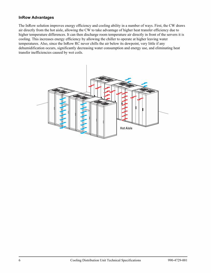
The InRow solution improves energy efficiency and cooling ability in a number of ways. First, the CW draws air directly from the hot aisle, allowing the CW to take advantage of higher heat transfer efficiency due to higher temperature differences. It can then discharge room temperature air directly in front of the servers it is cooling. This increases energy efficiency by allowing the chiller to operate at higher leaving water temperatures. Also, since the InRow RC never chills the air below its dewpoint, very little if any dehumidification occurs, significantly decreasing water consumption and energy use, and eliminating heat transfer inefficiencies caused by wet coils.
Hot Aisle
na2372a
6 Cooling Distribution Unit Technical Specifications 990-4729-001
Standard Features
Single Skin Panels
The frame is formed 16 gauge steel bolted together for maximum strength. The cabinet is serviceable from the front and both sides. All exterior panels and corner posts on the frame are powder coated for durability and an attractive finish. Front and back exterior panels are 18 gauge steel and the side exterior panels are 20 gauge steel. The front top and bottom panels are removable for easy access for service and installation.
Isolation and Balancing Valves
Each unit includes balancing / isolation valves on each circuit and isolation valves on the return for servicing. The valves provide coolant flow adjustment in one centralized location
Main Supply and Return Headers
Main supply and return headers supply coolant to the individual supply lines and return coolant to the Air Cooled Modular Chiller.
Multiple Distribution Supply and Return Lines
Up to 12 InRow RC units can be connected to allow scalability, which is required for medium to large data centers. These individual supply and return lines supply coolant to the individual CW units and return coolant to the main header.
Top or Bottom Distribution Piping Connections
Top or bottom connections provide the customer with the option of piping the unit from the top or the bottom, depending on the layout of their data center.
Pipe Fittings
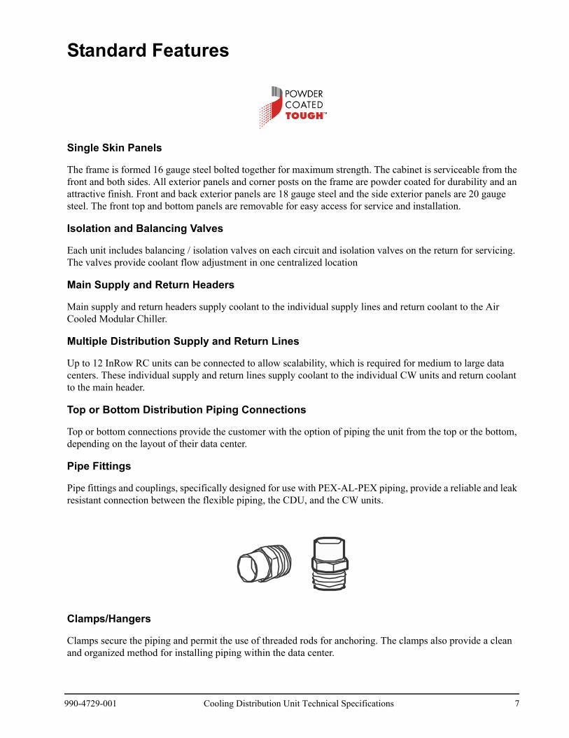
Pipe fittings and couplings, specifically designed for use with PEX-AL-PEX piping, provide a reliable and leak resistant connection between the flexible piping, the CDU, and the CW units.
Clamps/Hangers
Clamps secure the piping and permit the use of threaded rods for anchoring. The clamps also provide a clean and organized method for installing piping within the data center.
990-4729-001 Cooling Distribution Unit Technical Specifications 7
Jointless Piping
A jointless installation between the CDU and the InRow RC minimizes the potential for leaks, which enables the piping to be installed overhead above the aisles when a raised floor is not available.
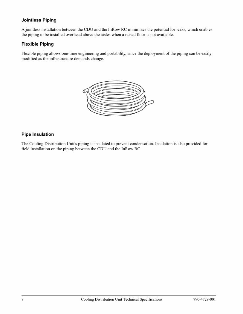
Flexible Piping
Flexible piping allows one-time engineering and portability, since the deployment of the piping can be easily modified as the infrastructure demands change.
Pipe Insulation
The Cooling Distribution Unit's piping is insulated to prevent condensation. Insulation is also provided for field installation on the piping between the CDU and the InRow RC.
8 Cooling Distribution Unit Technical Specifications 990-4729-001
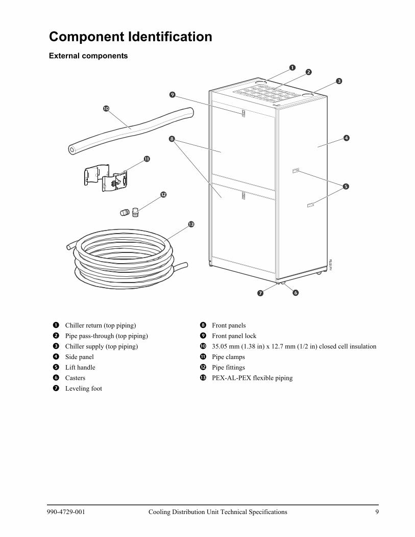
Component IdentificationExternal components
1 Chiller return (top piping) 8 Front panels
2 Pipe pass-through (top piping) 9 Front panel lock
3 Chiller supply (top piping) : 35.05 mm (1.38 in) x 12.7 mm (1/2 in) closed cell insulation
4 Side panel ; Pipe clamps
5 Lift handle < Pipe fittings
6 Casters = PEX-AL-PEX flexible piping
7 Leveling foot
na18
78a
990-4729-001 Cooling Distribution Unit Technical Specifications 9
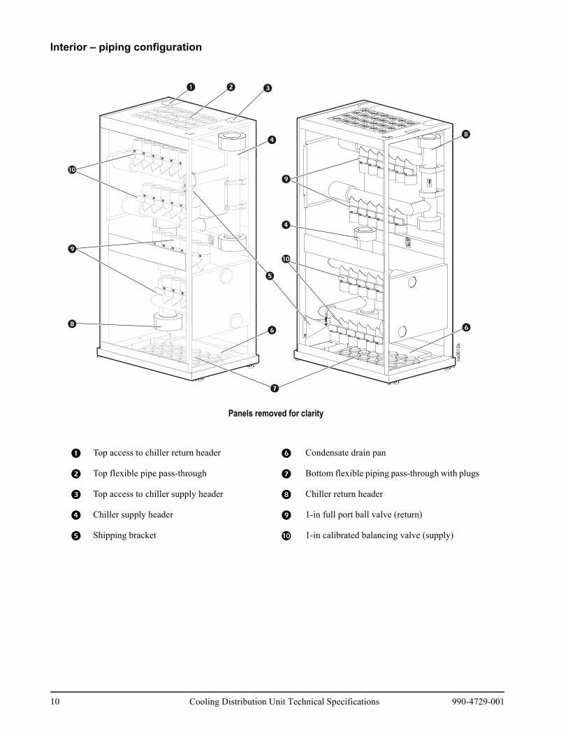
Interior – piping configuration
Panels removed for clarity
1 Top access to chiller return header 6 Condensate drain pan
2 Top flexible pipe pass-through 7 Bottom flexible piping pass-through with plugs
3 Top access to chiller supply header 8 Chiller return header
4 Chiller supply header 9 1-in full port ball valve (return)
5 Shipping bracket : 1-in calibrated balancing valve (supply)
10 Cooling Distribution Unit Technical Specifications 990-4729-001
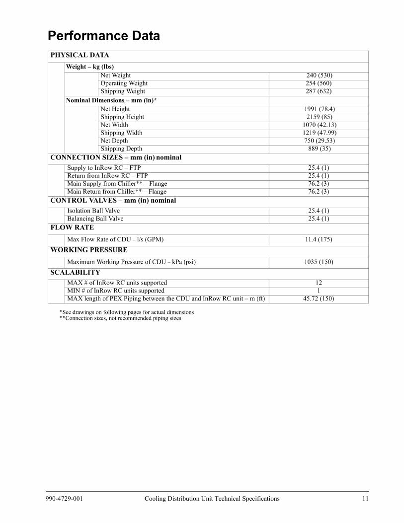
Performance Data
*See drawings on following pages for actual dimensions**Connection sizes, not recommended piping sizes
PHYSICAL DATAWeight – kg (lbs)
Net Weight 240 (530)Operating Weight 254 (560)Shipping Weight 287 (632)
Nominal Dimensions – mm (in)*Net Height 1991 (78.4)Shipping Height 2159 (85)Net Width 1070 (42.13)Shipping Width 1219 (47.99)Net Depth 750 (29.53)Shipping Depth 889 (35)
CONNECTION SIZES – mm (in) nominal Supply to InRow RC – FTP 25.4 (1)Return from InRow RC – FTP 25.4 (1)Main Supply from Chiller** – Flange 76.2 (3)Main Return from Chiller** – Flange 76.2 (3)
CONTROL VALVES – mm (in) nominalIsolation Ball Valve 25.4 (1)Balancing Ball Valve 25.4 (1)
FLOW RATEMax Flow Rate of CDU – l/s (GPM) 11.4 (175)
WORKING PRESSUREMaximum Working Pressure of CDU – kPa (psi) 1035 (150)
SCALABILITYMAX # of InRow RC units supported 12MIN # of InRow RC units supported 1MAX length of PEX Piping between the CDU and InRow RC unit – m (ft) 45.72 (150)
990-4729-001 Cooling Distribution Unit Technical Specifications 11
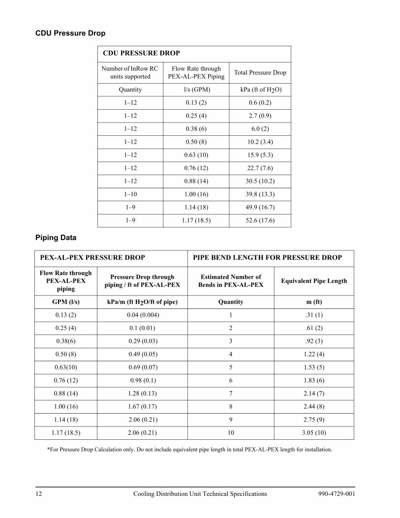
CDU Pressure Drop
Piping Data
*For Pressure Drop Calculation only. Do not include equivalent pipe length in total PEX-AL-PEX length for installation.
CDU PRESSURE DROP
Number of InRow RC units supported
Flow Rate through PEX-AL-PEX Piping Total Pressure Drop
Quantity l/s (GPM) kPa (ft of H2O)
1–12 0.13 (2) 0.6 (0.2)
1–12 0.25 (4) 2.7 (0.9)
1–12 0.38 (6) 6.0 (2)
1–12 0.50 (8) 10.2 (3.4)
1–12 0.63 (10) 15.9 (5.3)
1–12 0.76 (12) 22.7 (7.6)
1–12 0.88 (14) 30.5 (10.2)
1–10 1.00 (16) 39.8 (13.3)
1–9 1.14 (18) 49.9 (16.7)
1–9 1.17 (18.5) 52.6 (17.6)
PEX-AL-PEX PRESSURE DROP PIPE BEND LENGTH FOR PRESSURE DROP
Flow Rate through PEX-AL-PEX
piping
Pressure Drop through piping / ft of PEX-AL-PEX
Estimated Number of Bends in PEX-AL-PEX Equivalent Pipe Length
GPM (l/s) kPa/m (ft H2O/ft of pipe) Quantity m (ft)
0.13 (2) 0.04 (0.004) 1 .31 (1)
0.25 (4) 0.1 (0.01) 2 .61 (2)
0.38(6) 0.29 (0.03) 3 .92 (3)
0.50 (8) 0.49 (0.05) 4 1.22 (4)
0.63(10) 0.69 (0.07) 5 1.53 (5)
0.76 (12) 0.98 (0.1) 6 1.83 (6)
0.88 (14) 1.28 (0.13) 7 2.14 (7)
1.00 (16) 1.67 (0.17) 8 2.44 (8)
1.14 (18) 2.06 (0.21) 9 2.75 (9)
1.17 (18.5) 2.06 (0.21) 10 3.05 (10)
12 Cooling Distribution Unit Technical Specifications 990-4729-001
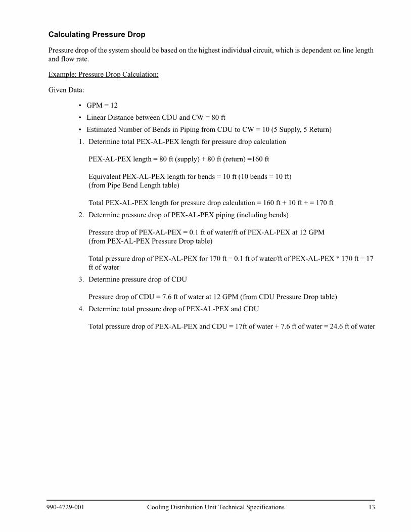
Calculating Pressure Drop
Pressure drop of the system should be based on the highest individual circuit, which is dependent on line length and flow rate.
Example: Pressure Drop Calculation:
Given Data:
• GPM = 12• Linear Distance between CDU and CW = 80 ft• Estimated Number of Bends in Piping from CDU to CW = 10 (5 Supply, 5 Return)1. Determine total PEX-AL-PEX length for pressure drop calculation
PEX-AL-PEX length = 80 ft (supply) + 80 ft (return) =160 ft
Equivalent PEX-AL-PEX length for bends = 10 ft (10 bends = 10 ft) (from Pipe Bend Length table)
Total PEX-AL-PEX length for pressure drop calculation = 160 ft + 10 ft + = 170 ft2. Determine pressure drop of PEX-AL-PEX piping (including bends)
Pressure drop of PEX-AL-PEX = 0.1 ft of water/ft of PEX-AL-PEX at 12 GPM (from PEX-AL-PEX Pressure Drop table)
Total pressure drop of PEX-AL-PEX for 170 ft = 0.1 ft of water/ft of PEX-AL-PEX * 170 ft = 17 ft of water
3. Determine pressure drop of CDU
Pressure drop of CDU = 7.6 ft of water at 12 GPM (from CDU Pressure Drop table)4. Determine total pressure drop of PEX-AL-PEX and CDU
Total pressure drop of PEX-AL-PEX and CDU = 17ft of water + 7.6 ft of water = 24.6 ft of water
990-4729-001 Cooling Distribution Unit Technical Specifications 13
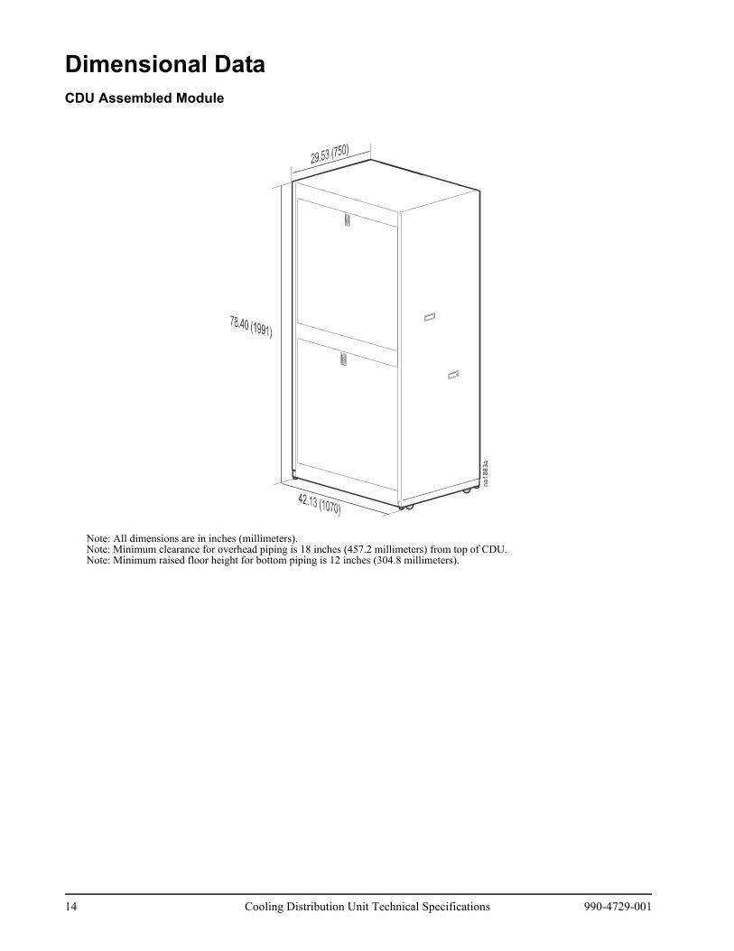
Dimensional DataCDU Assembled Module
Note: All dimensions are in inches (millimeters).Note: Minimum clearance for overhead piping is 18 inches (457.2 millimeters) from top of CDU.Note: Minimum raised floor height for bottom piping is 12 inches (304.8 millimeters).
na1883a
14 Cooling Distribution Unit Technical Specifications 990-4729-001
5(14
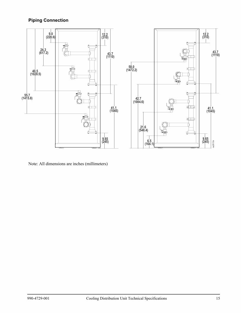
Piping Connection
Note: All dimensions are inches (millimeters)
42.7(1084.6)
58.0(1472.2)
21.6(548.4)
6.5(164.1)
9.65(245)
41.1
na2613a
43.7
12.2(310)
40.5(1028.5)
5.715.8)
24.3(617.2)
(228.6)9.0
9.65(245)
41.1
43.7
12.2(310)
990-4729-001 Cooling Distribution Unit Technical Specifications 15

Warranty
Three-Phase Power Products or Cooling Solutions One-Year Factory WarrantyThe limited warranty provided by American Power Conversion (APC™) in this Statement of Limited Factory Warranty applies only to products you purchase for your commercial or industrial use in the ordinary course of your business.
Terms of warrantyAPC warrants that the product shall be free from defects in materials and workmanship for a period of one year from the date of product start-up when start-up is performed by APC authorized service personnel and occurs within six months of the APC shipment date. This warranty covers repairing or replacing any defective parts including on-site labor and travel. In the event that the product fails to meet the foregoing warranty criteria, the warranty covers repairing or replacing defective parts at the sole discretion of APC for a period of one year from the shipment date. For APC cooling solutions, this warranty does not cover circuit breaker resetting, loss of refrigerant, consumables, or preventive maintenance items. Repair or replacement of a defective product or part thereof does not extend the original warranty period. Any parts furnished under this warranty may be new or factory-remanufactured.
Non-transferable warranty This warranty is extended to the first person, firm, association or corporation (herein referred to by “You” or “Your”) for whom the APC product specified herein has been purchased. This warranty is not transferable or assignable without the prior written permission of APC.
Assignment of warrantiesAPC will assign you any warranties which are made by manufacturers and suppliers of components of the APC product and which are assignable. Any such warranties are assigned “AS IS” and APC makes no representation as to the effectiveness or extent of such warranties, assumes no responsibility for any matters which may be warranted by such manufacturers or suppliers and extends no coverage under this Warranty to such components.
Drawings and descriptionsAPC warrants for the warranty period and on the terms of the warranty set forth herein that the APC product will substantially conform to the descriptions contained in the APC Official Published Specifications or any of the drawings certified and agreed to by contract with APC if applicable thereto (“Specifications”). It is understood that the specifications are not warranties of performance and not warranties of fitness for a particular purpose.
ExclusionsAPC shall not be liable under the warranty if its testing and examination disclose that the alleged defect in the product does not exist or was caused by end user or any third person’s misuse, negligence, improper installation or testing. Further, APC shall not be liable under the warranty for unauthorized attempts to repair or modify wrong or inadequate electrical voltage or connection, inappropriate on-site operation conditions, corrosive atmosphere, repair, installation, start-up by non-APC designated personnel, a change in location or operating use, exposure to the elements, Acts of God, fire, theft, or installation contrary to APC recommendations or specifications or in any event if the APC serial number has been altered, defaced, or removed, or any other cause beyond the range of the intended use.
990-4729-001 Cooling Distribution Unit Technical Specifications 17
THERE ARE NO WARRANTIES, EXPRESS OR IMPLIED, BY OPERATION OF LAW OR OTHERWISE, OF PRODUCTS SOLD, SERVICED OR FURNISHED UNDER THIS AGREEMENT OR IN CONNECTION HEREWITH. APC DISCLAIMS ALL IMPLIED WARRANTIES OF MERCHANTABILITY, SATISFACTION AND FITNESS FOR A PARTICULAR PURPOSE. APC EXPRESS WARRANTIES WILL NOT BE ENLARGED, DIMINISHED, OR AFFECTED BY AND NO OBLIGATION OR LIABILITY WILL ARISE OUT OF, APC RENDERING OF TECHNICAL OR OTHER ADVICE OR SERVICE IN CONNECTION WITH THE PRODUCTS. THE FOREGOING WARRANTIES AND REMEDIES ARE EXCLUSIVE AND IN LIEU OF ALL OTHER WARRANTIES AND REMEDIES. THE WARRANTIES SET FORTH ABOVE CONSTITUTE APC’S SOLE LIABILITY AND PURCHASER’S EXCLUSIVE REMEDY FOR ANY BREACH OF SUCH WARRANTIES. APC WARRANTIES EXTEND ONLY TO PURCHASER AND ARE NOT EXTENDED TO ANY THIRD PARTIES.
IN NO EVENT SHALL APC, ITS OFFICERS, DIRECTORS, AFFILIATES OR EMPLOYEES BE LIABLE FOR ANY FORM OF INDIRECT, SPECIAL, CONSEQUENTIAL OR PUNITIVE DAMAGES, ARISING OUT OF THE USE, SERVICE OR INSTALLATION, OF THE PRODUCTS, WHETHER SUCH DAMAGES ARISE IN CONTRACT OR TORT, IRRESPECTIVE OF FAULT, NEGLIGENCE OR STRICT LIABILITY OR WHETHER APC HAS BEEN ADVISED IN ADVANCE OF THE POSSIBILITY OF SUCH DAMAGES. SPECIFICALLY, APC IS NOT LIABLE FOR ANY COSTS, SUCH AS LOST PROFITS OR REVENUE, LOSS OF EQUIPMENT, LOSS OF USE OF EQUIPMENT, LOSS OF SOFTWARE, LOSS OF DATA, COSTS OF SUBSTITUENTS, CLAIMS BY THIRD PARTIES, OR OTHERWISE.
NO SALESMAN, EMPLOYEE OR AGENT OF APC IS AUTHORIZED TO ADD TO OR VARY THE TERMS OF THIS WARRANTY. WARRANTY TERMS MAY BE MODIFIED, IF AT ALL, ONLY IN WRITING SIGNED BY AN APC OFFICER AND LEGAL DEPARTMENT.
Warranty claims Customers with warranty claims issues may access the APC customer support network through the Support page of the APC Web site, www.apc.com/support. Select your country from the country selection pull-down menu at the top of the Web page. Select the Support tab to obtain contact information for customer support in your region.
18 Cooling Distribution Unit Technical Specifications 990-4729-001
Guide Specifications
Guide Specifications for the CDUTHIS GUIDE SPECIFICATION IS WRITTEN IN ACCORDANCE WITH THE CONSTRUCTION SPECIFICATIONS INSTITUTE (CSI) MASTERFORMAT. THIS SECTION MUST BE CAREFULLY REVIEWED AND EDITED BY THE ARCHITECT OR THE ENGINEER TO MEET THE REQUIREMENTS OF THE PROJECT. COORDINATE THIS SECTION WITH OTHER SPECIFICATION SECTIONS IN THE PROJECT MANUAL AND WITH THE DRAWINGS.WHERE REFERENCE IS MADE THROUGHOUT THIS SECTION TO “PROVIDE”, “INSTALL”, “SUBMIT”, ETC., IT SHALL MEAN THAT THE CONTRACTOR, SUBCONTRACTOR, OR CONTRACTOR OF LOWER TIER SHALL “PROVIDE”, “INSTALL”, SUBMIT”, ETC., UNLESS OTHERWISE INDICATED. THIS SECTION IS WRITTEN TO INCLUDE THE 2004 MASTERFORMAT AND THE 1995 MASTERFORMAT VERSIONS. WHERE APPLICABLE, THESE ITEMS ARE BRACKETED AND, IN EACH CASE, UNLESS OTHERWISE INDICATED, THE FIRST CHOICE APPLIES TO THE 2004 MASTERFORMAT AND THE SECOND CHOICE APPLIES TO THE 1995 MASTERFORMAT.
PART 1 — GENERAL
1.1 SUMMARY
A. These specifications describe requirements for a system designed for cooling distribution to modular InRow CW air conditioners. The system shall be designed to distribute and balance the chilled water / glycol using flexible jointless piping to the air conditioners. The manufacturer shall design and furnish all the piping and fittings required for cooling distribution from the distribution unit to the InRow CW units.
1.2 DESIGN REQUIREMENTS
A. The cooling distribution unit, manufactured by APC by Schneider Electric, shall include a supply and return distribution manifold. Each manifold should include 12 pipe branches with shut-off and balancing valves. The unit shall be as described in the following specification as manufactured by APC by Schneider Electric.
1. Model number:2. Total number of InRow CW units:3. Flow per circuit: (gpm)4. Water pressure drop through the CDU:
B. The unit shall be factory-assembled with isolation and balancing valves and shall be designed to be used with jointless flexible piping.
1.3 SUBMITTALS
A. Submittals shall be provided with the proposal and shall include: overall dimensions of the unit, total of circuits used, maximum chilled water/glycol flow per circuit, calculated run of flexible piping per circuit, and piping connection drawings at the CDU and at the InRow CW.
990-4729-001 Cooling Distribution Unit Technical Specifications 19
1.4 QUALITY ASSURANCE
A. The unit shall be factory tested prior to shipment. Testing shall include complete pressure and leak testing to ensure system integrity. The system shall be inspected for quality control before shipment.
B. The unit shall be UL Listed to UL 1995 and CSA C22.2 No. 236.
1.5 WARRANTY
A. The system parts shall be provided with a warranty against defects for a period of 12 months from date of shipment from the factory.
PART 2 — PRODUCTS
2.1 STANDARD COMPONENTS
A. Cabinet Construction
1. The frame shall be 16 gauge formed steel and bolted together. 2. The front and back exterior panels shall be 18 gauge steel and the side exterior panels shall be 20
gauge steel.3. All exterior panels and corner posts on the frame shall be powder coated black. The unit shall
include front removable panels to allow access for system balancing and service and side removable panels to allow for main piping connections.
4. The front panels shall have provisions to be locked with a key.5. The unit shall include casters for easy installation and leveling feet at each corner.6. All piping, including headers and distribution lines, shall be insulated with 1/2 in
(12.7 mm) closed cell insulation.
B. Connections
1. The main supply line can be piped from either the top or bottom of the unit. The distribution lines are dependent on the version of the unit: top piped or bottom piped. The dielectric flanges allow the unit to be connected to the building chilled water system using copper or iron piping.
C. Valves
1. Each supply branch shall be 1 in (25.4 mm) I.D. and shall include a balancing and shut-off valve to provide a single point of balancing at the distribution unit.
2. Each return branch shall be 1 in (25.2 mm) I.D. and shall include a ball valve for isolation.3. A 1/4 in (6.35 mm) male flare port with Schrader valve shall be included in each supply and return
branch for pressure test and drain.
D. Drain Pan
1. A drain pan with a 1/4 in (6.35 mm) plastic tube connection shall be included at the bottom of the unit.
20 Cooling Distribution Unit Technical Specifications 990-4729-001
E. Flexible Piping
1. Jointless flexible piping shall be used for chilled water/glycol distribution from the CDU to the InRow CW units.
2. The piping shall be crosslinked polyethylene/aluminum/crosslinked polyethylene tubing (PEX-AL-PEX) manufactured by PEX-b method.
3. The temperature and pressure ratings of the piping shall be: 200°F (93.3°C) at 100 psi (689.5 kPa), 180°F (82.2°C) at 125 psi (861.8 kPa), and 73°F (22.8°C) at 200 psi (1378.9 kPa).
4. Piping shall conform with ASTM Standard: ASTM E814, ASTMF1281, and NSF Standard: NSF-PW 14 and 61.
5. Piping length shall not exceed 150 ft (45.72 m) from the CDU to the air conditioner and it shall only include fittings at the CDU and at the InRow CW.
6. Pipe connections to the CDU and InRow CW shall be made with pipe fittings that are crimped at each connection to ensure no leakage in the system.
7. All PEX-AL-PEX piping shall be insulated in the field with 1/2 in (12.7 mm) closed cell insulation.
F. Pipe Clamps
1. Pipe clamps shall be factory provided and field installed at least every 32 in (812.8 mm) when piping is installed overhead to properly secure the PEX-AL-PEX piping to the ceiling. (Refer to local codes for exact spacing requirements.)
2. The clamps shall include a center hole that permits the use of a 3/8 in (9.5 mm) threaded rod for anchoring.
G. Insulation—Insulation shall be 1.38 in (35.05 mm) in diameter by 1/2 in (12.7 mm) thick closed cell insulation.
PART 3 — EXECUTION
3.1 IMPLEMENTATION
A. Installation
1. Installation of the system shall be in accordance to the Guidelines for Installation by the manufacturer.
2. Installation shall be performed by the manufacturer or supervised by the manufacturer’s service representative.
3. Installation of piping and connections from the Cooling Distribution Unit to the InRow CW units shall be performed by the manufacturer or supervised by the manufacturer’s service representative.
Note: The minimum clearance for overhead piping is 18 in (457.2 mm) from the top of the CDU to the ceiling. The minimum raised floor height for units configured for bottom piping is 12 in (304.8 mm).
B. Start-up
1. Start-up of the Cooling Distribution Unit shall be performed by the manufacturer.
990-4729-001 Cooling Distribution Unit Technical Specifications 21
PART 4 — GUIDELINES FOR INSTALLATION
4.01 GENERAL
A. The CDU provides reliable and flexible fluid distribution to the InRow CW in medium to large data centers (including high density applications). The unit incorporates flexible and jointless piping to provide you with a scalable fluid distribution system that minimizes the risk of leaks within the data center. The CDU will provide years of trouble-free service, when installed by technically qualified personnel.
4.2 SERVICE ACCESS
A. The InfraStruXure CDU is designed to be a stand-alone unit. It can be placed against a wall or in any open area that is suitable for use. Both side and front panels may be removed during the installation process. An area of 36 in (915 mm) of clear floor space in front and 24 in (609.5 mm) at each side of the unit is required for installation. For service, an area of 36 in (914 mm) of clear floor space in front of the CDU is required. All required maintenance can be performed from the front of the unit.
4.3 RECEIVING THE UNIT
A. Your CDU has been completely tested and inspected prior to shipment. To ensure that you have received the unit in excellent condition, perform a careful inspection of the crating and the unit immediately upon receipt. Verify that all parts ordered were received as specified. Report any damage discovered to the freight carrier. If necessary, contact the APC by Schneider Electric field service department for help in repairing or replacing damaged parts. While APC by Schneider Electric is not responsible for damage incurred in transit, we want to make sure that you have no undue delays in your system start-up.
4.4 RIGGING
A. The unit is manufactured with a formed steel frame for maximum strength and unit integrity. However, as with all electrical and mechanical equipment, you must take care with proper rigging of your unit.
B. When using a forklift to move the unit, use the shipping skid to protect the bottom of the unit. When using chains, cables or rope to lift the unit, use spreader bars to prevent damage to the finished panels.
Note: Due to the ongoing program dedicated to product improvement, specifications are subject to revisions without notice. APC by Schneider Electric assumes no responsibility, and disclaims all liability for damages resulting from use of this information or for any errors or omissions.
22 Cooling Distribution Unit Technical Specifications 990-4729-001

Worldwide Customer SupportCustomer support is available at no charge via e-mail or telephone. Contact information is available at www.apc.com/support/contact.
12/6/12990-4729-001
© APC by Schneider Electric. APC and the APC logo are owned by Schneider Electric IndustriesS.A.S., American Power Conversion Corporation, or their affiliated companies. All other trademarksare property of their respective owners.