Embed Size (px)
Citation preview

Converters: Digital to Analogue Presented by:
Dr. Walid Ghoneim
References:
Process Control Instrumentation Technology, Curtis Johnson
Op Amps Design, Operation and Troubleshooting. David Terrell
Analog Interfacing to Embedded Microprocessors. Stuart Ball
Comparator:

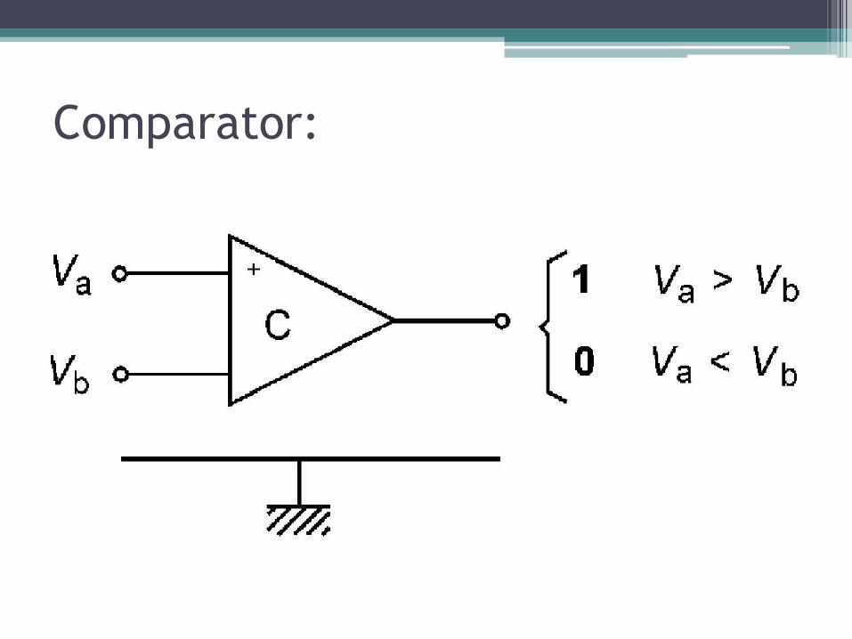
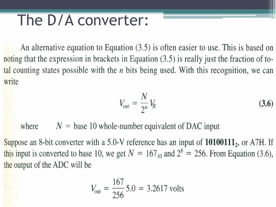
The D/A converter:

The D/A converter: • It converts the controller output from a digital number o an analog voltage
or current for use by the external analog device.
• Since the digital input has a finite number of digital combinations, the resulting analog output also has a limited number of possible values (stepped).
• The greater the number of possible values, the closer the analog output will be to the ideal value.
• The number of possible levels is determined by the number of bits, which is computed as (2^n – 1) where n is the number of bits in the digital number.
• For example, an 8-bit D/A converter could be expected to produce (2^8–1), or 255, discrete output steps.
• If the full-scale range of the converter is 0 to 10 volts, then each step will be 10/255, or about 39.2 millivolts (resolution).
• If finer resolution is required, we need more bits in the digital number.
• Thus, a converter with 10-bit resolution would provide (2^10-1), or 1023 steps with each step being equivalent to 10/1023, or about 9.77 millivolts.

The D/A converter: • Accuracy of a D/A converter describes the amount of error between the
• actual output of the converter and the theoretical output for a given input
number.
• Settling time: the total time required for the analog output to stabilize
after a new digital number has been applied to the DAC input
• It is equal to the sum of the propagation time and the slew rate time.
• The overall range can be shifted up or down from the optimum point.
• This DC offset is called offset error.
• One end of the range can be correct but the other extreme too high or too
low. This is called a gain error or scaling error.
• We want a monotonic output, the output should increase whenever the
input number increases.
• However, it is possible for a D/A converter to have a reduction in analog
output at a particular point in its range, even though the digital input is
increasing uniformly.

The D/A converter:
• There are the 16 distinct output levels; however, the steps are not equal
in amplitude (linearity problems)
• The midpoint level actually increases instead of decreases (nonmonotonic)
• There are several glitches caused by switching transients.

The D/A converter:
The D/A converter:

The D/A converter:

The D/A converter:
The D/A converter:

The D/A converter:

The D/A converter:

The D/A converter:

The D/A Types: Weighted DAC • Identical to the inverting summing Amplifier.
• The resistances are binary weighted: R, 2R, 4R, 8R, 16R, 32R, ….. (2^n)R
The D/A Types: Weighted DAC • The scaling factor for the converter is such that each step in the
output corresponds to x volts.
• Although the full-scale digital input for a 4-bit DAC will always be 1111 (decimal 15), its full-scale output can be 15, 10, 5 volts,
or any other number depending upon the scale factor of the converter circuit.
• For satisfactory performance, the input resistors must be very
carefully selected (i.e., precision values) in order to maintain the correct ratios.
• If one or more resistors are the wrong value, the output will exhibit problems such as poor linearity and/or lack of monotonicity.

The D/A Types: Weighted DAC • Even with careful selection of resistors, the simple weighted
D/A converter is only useful for small numbers of bits, since the
ratio of the smallest to the largest resistor quickly becomes impractical — that is, the ratio increases as 2^(n-1), where n is
the number of bits in the input.
• Ex., R in the least significant input of a 10-bit DAC is 2^(10-1), or 512 times R for the most significant input.
• A variation of the basic weighted D/A converter involves dividing the bits into two or more groups and converting each
group separately.
• The weighting resistors for each group are identical, and the outputs from each of the individual converters can then be
summed into a weighted, summing amplifier to produce the final output. Design it !!!

The D/A Types: R2R Ladder DAC
• One of the most popular methods for D/A conversion.
• One advantage of the R2R converter over the weighted converter is that the resistors have a 2:1 ratio regardless of the number of bits being converted.
• This makes matching resistors much easier and even makes the use of integrated resistors practical.
• To analyze the operation of the circuit, Thevenize the input circuit for one or more digital input numbers.

The D/A Types: R2R Ladder DAC
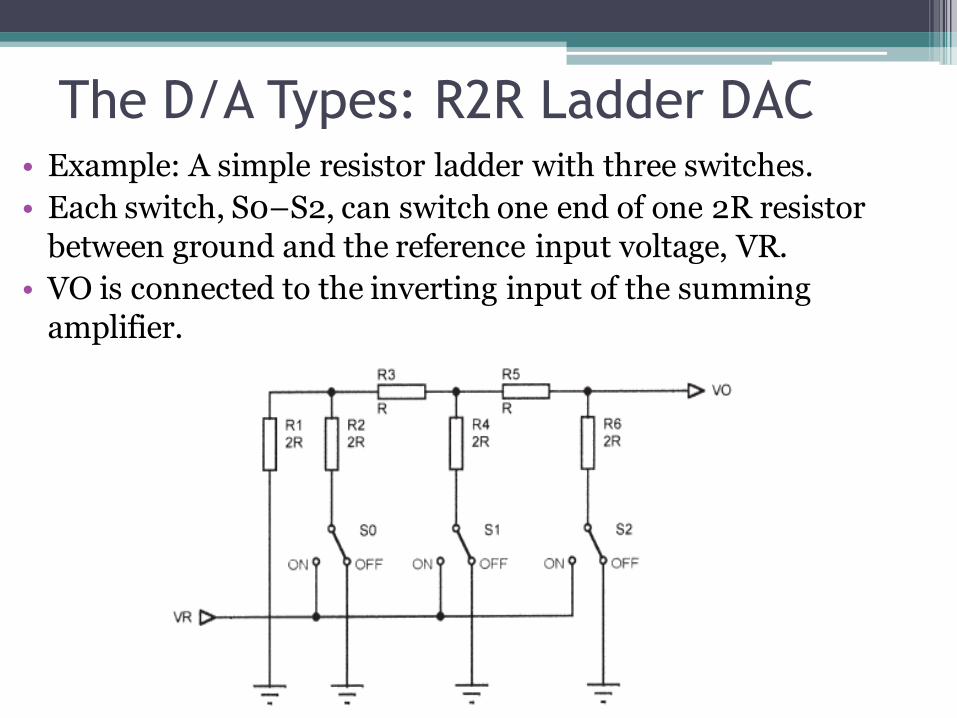
• Example: A simple resistor ladder with three switches.
• Each switch, S0–S2, can switch one end of one 2R resistor
between ground and the reference input voltage, VR.
• VO is connected to the inverting input of the summing
amplifier.
The D/A Types: R2R Ladder DAC

• What happens when switch S2 is ON (connected to VR) and S1 and S2 are OFF (connected to ground).
• By calculating the resulting series/parallel resistor network, the final output voltage (VO) turns out to be .5 * VR.
The D/A Types: R2R Ladder DAC

• If we similarly calculate VO for all the other switch combinations, we get :
The D/A Types: R2R Ladder DAC
The D/A Types: R2R Ladder DAC • The actual performance of an inexpensive R2R ladder DAC is examined.
• Although the linearity is less than optimum, it illustrates the principles involved and would be adequate for many D/A applications.
• The linearity could be greatly improved by using precision resistors (rather than 5 % ones) and by driving the digital inputs via analog switches (rather than directly from the output of a digital counter).
• Figure (a) shows the actual output of the converter, with the 16 distinct output levels in the waveform easily seen, while figure (b) shows the same basic circuit after the output has gone through a simple low-pass filter.
• The abrupt changes in the output are now gone, leaving us with a cleaner analog signal.
• For noncritical applications, making your own D/A converters is feasible.
• However, the low cost and high performance (e.g., laser-trimmed ladder resistors) available in integrated converters makes these devices the best choice for many applications. An example of such a device is the TDC1016 10-bit D/A converter manufactured by Raytheon Semiconductor

The D/A Types: R2R Ladder DAC


![[PPT]Chapter 1 – The Demand for Audit and Other Assurance …papers.aast.edu/staffcourses/157_37315_EY315_2013_1__1_1... · Web viewThe Demand for Audit and Other Assurance Services](https://img.pdfslide.us/doc/110x75/5add8c317f8b9a8b6d8d1416/pptchapter-1-the-demand-for-audit-and-other-assurance-viewthe-demand-for.jpg)