Embed Size (px)
Citation preview
AIAA-2014-3623
1 American Institute of Aeronautics and Astronautics
50th Joint Propulsion Conference & Exhibit, Cleveland, OH, July 28 - 30, 2014
Conventional and Bimodal Nuclear Thermal Rocket (NTR) Artificial Gravity Mars Transfer Vehicle Concepts
Stanley K. Borowski1, David R. McCurdy
2 and Thomas W. Packard
2
NASA Glenn Research Center, Cleveland, OH, 44135
A variety of countermeasures have been developed to address the debilitating physiological effects of “zero-gravity” (0-g) experienced by cosmonauts and astronauts during their ~0.5 – 1.2 year long stays in LEO. Longer interplanetary flights, combined with possible prolonged stays in Mars orbit, could subject crewmembers to up to ~2.5 years of weightlessness. In view of known and recently diagnosed problems associated with 0-g, an artificial gravity spacecraft offers many advantages and may indeed be an enabling technology for human flights to Mars. A number of important human factors must be taken into account in selecting the rotation radius, rotation rate, and orientation of the habitation module or modules. These factors include the gravity gradient effect, radial and tangential Coriolis forces, along with cross-coupled acceleration effects. Artificial gravity (AG) Mars transfer vehicle (MTV) concepts are presented that utilize both conventional NTR, as well as, enhanced “bimodal” nuclear thermal rocket (BNTR) propulsion. The NTR is a proven technology that generates high thrust and has a specific impulse (Isp) capability of ~900 s – twice that of today’s best chemical rockets. The AG/MTV concepts using conventional NTP carry twin cylindrical “ISS-type” habitation modules with their long axes oriented either perpendicular or parallel to the longitudinal spin axis of the MTV and utilize photovoltaic arrays (PVAs) for spacecraft power. The twin habitat modules are connected to a central operations hub located at the front of the MTV via two pressurized tunnels that provide the rotation radius for the habitat modules. For the BNTR AG/MTV option, each engine has its own “closed” secondary helium-xenon gas loop and Brayton rotating unit that can generate 10’s of kilowatts (kWe) of spacecraft electrical power during the mission coast phase eliminating the need for large PVAs. A single inflatable “TransHab-type” habitation module is also used with multiple vertical floors oriented radial to the MTV spin axis. The BNTR MTV’s geometry – long and linear – is naturally compatible with AG operation. By rotating the vehicle about its center-of-mass and perpendicular to its flight vector at ~3.0 – 5.2 rpm, a centrifugal force and AG environment corresponding to ~0.38 – 1.0 g can be established to help maintain crew fitness out to Mars and back. Vehicles using NTP/BNTP can more readily accommodate the heavier payload mass and increased RCS propellant loading associated with AG operation, and can travel faster to and from Mars thereby reducing the crew’s exposure to galactic cosmic radiation and solar flares. Mission scenario descriptions, key vehicle features and operational characteristics for each propulsion options are presented using the lift capability and payload volumes estimated for the SLS-1A and HLV.
Nomenclature g = Earth’s gravitational field (~9.807 m/s
2)
IMLEO = initial mass in low Earth orbit
klbf = thrust (1000’s of pounds force)
LEO = Low Earth Orbit (= 407 km circular)
NTP/BNTP = Nuclear Thermal / Bimodal Nuclear Thermal Propulsion
SLV/HLV = Space Launch System / Heavy Lift Vehicle
VIIP = Visual Impairment due to increased Intracranial Pressure
ΔV = velocity change increment (km/s)
------------------------------------------------------ 1LTR Branch and Technical Lead, NTP Systems, 21000 Brookpark Road, MS: 86-4, AIAA Associate Fellow
2Vantage Partners, LLC at Glenn Research Center, 3000 Aerospace Parkway, Brook Park, OH 44142
https://ntrs.nasa.gov/search.jsp?R=20140017461 2018-07-11T09:29:35+00:00Z

AIAA-2014-3623
2 American Institute of Aeronautics and Astronautics
50th Joint Propulsion Conference & Exhibit, Cleveland, OH, July 28 - 30, 2014
I. Introduction and Background n the 2033 – 2035 timeframe, human exploration missions to Mars could begin provided there is a true national /
international commitment to this endeavor that is backed up by realistic, sustained funding necessary to develop
the critical technologies needed to make this dream a reality [1]. Initial missions could be orbital precursors used to
check out the key components (e.g., the propulsion and life support systems) of the MTV. Such a mission would
require ~18 months in a 0-g environment with the crew spending ~60 days in Mars orbit. Follow-on landing
missions could expose the crew to Mars gravity (~0.38-g) for long periods (up to ~18 months) plus 6-month transits
to and from Mars in 0-g. In the event of an abort back to orbit during or shortly after landing [2], the crew could be
subjected to ~2.5 years of weightlessness aboard the MTV. In view of the known debilitating physiological effects
[3] associated with prolonged exposure to 0-g, and recent emerging health concerns such as VIIP syndrome [4], an
artificial gravity spacecraft using NTP offers many advantages (including reduced trip times) and may indeed be an
enabling technology for future human flights to Mars and beyond.
A variety of AG/MTV concepts were developed by the Martin Marietta Astronautics Group for NASA’s Mars
Exploration Case Studies [5,6,7] in 1988 – 89. Each of these concepts used a large diameter (~39 – 46 m) aerobrake
(AB) with a low lift to drag (L/D) ratio of ~0.2 for Mars orbit capture (MOC). These large ABs required assembly in
LEO before being outfitted with habitation, auxiliary PVA power and chemical propulsion system elements within
their protective envelope. By rotating the AB about its central axis at different spin rates and mounting the habitat
modules near the outer perimeter of the AB to increase the rotation radius, a range of centrifugal forces can be
generated for the crew during the transit out to Mars and back. A sampling of these AB concepts (minus their
multiple expendable trans-Mars injection (TMI) stages) is shown in Fig 1.
Figure 1. AG/MTV Concepts Using Aerobraking, Chemical Propulsion and Tethers [8]
Concept 1 was developed for a large crew of 12 – 18 astronauts. It carried eight cylindrical Space Station Freedom
(SSF)-type habitation modules arranged in a ring to provide a 100-m long circular jogging track. The modules were
mounted to a large 45.6-m diameter AB sized for aerocapture at both Mars and again at Earth for spacecraft
recovery and possible reuse. This very large spacecraft had an IMLEO > 1500 metric tons (1 t = 1000 kg). Concept
2 carried 8 astronauts and used four SSF habitat modules arranged in a “Bent-I” configuration inside a 41-m
diameter AB. Two pressurized tunnels connected the four habitat modules to a central logistics and docking hub to
which the Mars Descent / Ascent Vehicle (MDAV) was attached. The IMLEO for Concept 2 was ~1091 t. Concept
3 utilized a deployable flexible fabric AB (~39-m in diameter) and carried two cylindrical hab modules each with
five separate floors arranged perpendicular to the modules’ long axis. The modules were attached to the central
logistics and docking hub using swivel joints allowing them to swing outward to increase their rotation radius during
AG operation. The modules were cranked back inside the protective envelope of the AB prior to MOC. The modules
housed 5 - 7 crew and the total mission IMLEO was ~687 t including the four expendable TMI stages. Concepts 4
I

AIAA-2014-3623
3 American Institute of Aeronautics and Astronautics
50th Joint Propulsion Conference & Exhibit, Cleveland, OH, July 28 - 30, 2014
and 5 used dual retractable tethers to separate paired or individual hab modules from the AB and primary propulsion
system. With tether lengths of approximately several hundred meters, rotations rates as low as 2 revolutions per
minute (rpm) could provide ~1-g of centrifugal acceleration for the crew.
Each of the above concepts had a number of drawbacks [8]. Concepts 1 and 2 were very large, required
significant orbital assembly for the AB and overall vehicle, and had large IMLEO requirements (>1000 t). Concept
3 required an internal arrangement for the hab modules that differed from that of the SSF habitation modules used in
the other designs. It also required movement of two major pressurized mechanical joints. With tethered Concepts 4
and 5, the reaction control system (RCS) propellant requirements to initiate and stop vehicle rotation were larger,
and the dynamic control problems more severe during the deployment and retraction process, as well as during
vehicle spin up and spin down. A tether break or reel freeze-up could also be a critical failure mode. From an
operational standpoint, once deployed, the crew in Concept 4 would be isolated from the systems enclosed within
the aerobrake (e.g., MDAV) and in Concept 5, isolated from each other as well.
To avoid the deficiencies of the above concepts, Martin Marietta proposed Concept 6 [8], an AG/MTV design
that used chemical propulsion and carried twin cylindrical SSF habitation modules whose long axes were oriented
perpendicular to the longitudinal spin axis of the MTV – referred to as the Dumbbell B configuration (Fig. 2). The
hab modules were connected to a central logistics and docking hub by two pressurized tunnels each ~12.5 m long.
Each hab module – designed to accommodate 2 - 3 crewmembers – had excess capacity so that either could serve as
a safe haven for the entire crew in case of an emergency. Attached to the Sun-facing side of each tunnel and hab
module were ~30 m2 and 75 m
2, respectively, of PVAs producing ~26 kWe of electrical power for the spacecraft’s
various systems. Once fully assembled, the rotation radius from the center of the logistics module to the floor of
each hab module was ~17 m allowing centrifugal acceleration levels ranging from 0.38-g to 0.68-g for vehicle spin
rates of 4.5 to 6 rpm. At a slightly higher spin rate of 7.25 rpm, 1-g could be achieved. The pressurized logistics hub
also provided a shirt-sleeve environment and anytime crew access to the MDAV docked to the front of the vehicle.
Figure 2. Key Features and Components of the Concept 6 AG/MTV
The aft end Mars orbit capture stage (MOCS) and forward trans-Earth injection stages (TEIS) used four ~25 klbf
liquid oxygen / liquid hydrogen (LOX/LH2) RL-10B-2 engines with a Isp of ~460 s. The MOCS also functioned as
the trans-Mars injection stage (TMI) stage using propellant supplied from six surrounding drop tanks jettisoned in
pairs as they are drained. The vehicle IMLEO at TMI is ~710.8 t.

AIAA-2014-3623
4 American Institute of Aeronautics and Astronautics
50th Joint Propulsion Conference & Exhibit, Cleveland, OH, July 28 - 30, 2014
In 1999, GRC introduced to NASA’s DRM 4.0 study an AG/MTV design that utilized “bimodal” nuclear thermal
rocket (BNTR) propulsion [2,9]. DRM 4.0 featured a “split mission” approach with two minimum energy cargo
flights used to pre-deploy orbital and surface assets at Mars ahead of the crew. The crewed MTV departed LEO ~26
months later and utilized a higher energy, “fast conjunction” trajectory out to Mars and back. Though the “1-way”
transit times for the crew were short (~5-7 months), stay times at Mars were long (~500 days or more to allow
proper realignment between Mars and Earth for the crew’s return to Earth). In the event an aborted landing or major
surface system failure shortly after landing forced an early return to the orbiting MTV, the crew could spend the
entire mission duration (~2.5 years) in a weightless environment.
The BNTR AG/MTV, named von Braun and shown in Fig. 3, eliminated this problem. With its bimodal engines
providing both efficient high thrust propulsion and “24/7” electrical power, the spacecraft no longer needed to
deploy and operate large Sun-tracking PVAs, and its configuration – long and linear – was naturally compatible with
AG operations. Following the TMI maneuver, the drop tank enclosed within the saddle truss was jettisoned in
preparation for vehicle spin up. By rotating the vehicle about its center-of-mass and perpendicular to its flight vector
(illustrated at the bottom of Fig. 3), a centrifugal force and AG environment could be established to help maintain
crew fitness during the transit out to Mars and back, also while in Mars orbit in the event of an “abort-to-orbit”.
Figure 3. Artificial Gravity “Bimodal” NTR Crewed MTV – Mars DRM 4.0 (1999)
The von Braun had an IMLEO of ~166.4 t [9]. Its “core” propulsion and power stage used three 15 klbf BNTR
engines. Each engine had its own 25 kWe Brayton rotating unit (BRU) operated at 2/3rd
of rated power (~17 kWe) to
produce the 50 kWe of total electrical power needed to run the crewed MTV. If an engine or BRU were lost, the
remaining two units would be ramped up to 25 kWe to produce the required power level. During the outbound transit
to Mars, the von Braun rotated at ~4 rpm to produce a centrifugal acceleration of ~0.38-g. On the return leg, its
rotation rate was increased to ~6 rpm to produce near Earth gravity conditions (~0.79-g). At a slightly higher spin
rate of 6.8 rpm, 1-g was achievable.
In that same year (1999), an AG Workshop, sponsored by NASA and the National Space Biomedical Research
Institute (NSBRI), was held in League City, Texas [10]. In the executive summary of Ref. 10 it was recommended
that NASA appropriate the necessary resources to initiate AG parametric studies both on the ground and in space. It
also recommended that NASA establish an AG working group to monitor and assess progress being made in this
area. Five years later, in 2004, the International Academy of Astronautics (IAA) set up a Study Group on AG and
used as its starting point the set of questions and recommendations from the 1999 AG Workshop. The Study Group
recognized that a combination of exercise and pharmaceuticals alone were unlikely to counter the anticipated effects
of long-term crew exposure to the 0-g and partial-g environments of a Mars mission. So the question was again
asked – Are rotating AG vehicles needed for Mars? Answering this question requires an understanding of the AG

AIAA-2014-3623
5 American Institute of Aeronautics and Astronautics
50th Joint Propulsion Conference & Exhibit, Cleveland, OH, July 28 - 30, 2014
trade space and the relative importance of the physiological, medical, human factors, environmental, and
engineering components that it includes. While acknowledging this larger picture, the Study Group’s final report
[11] focused its attentions on the biomedical aspects of this trade space. It strongly recommended bringing back
animal research to ISS in order to get early, in-fight data, also developing a space-based short-radius centrifuge as a
means of assessing the effectiveness on humans of intermittent, short arm centrifugation inside a spacecraft.
In 2007 – 2008, NASA conducted another inter-center, multi-directorate study on the requirements and concepts
needed for a human Mars mission. Known as the Mars Design Reference Architecture (DRA) 5.0 study [12], its
purpose was to provide an update to the earlier DRM 4.0 study conducted in 1999. Both short and long surface stay
landing missions were considered and the “fast conjunction” long stay option was again selected because it provided
sufficient time at Mars for the crew to explore the planet’s rich geological diversity while also reducing the crew’s
transit times to and from Mars to ~6 months, or ~1 year in deep space. A variety of propulsion options were also
proposed – chemical, NTP, solar and nuclear electric propulsion (SEP/NEP) – but only chemical and NTP were
considered because of their maturity and their ability to provide short transit times.
The NTR was ultimately selected as the propulsion system of choice for DRA 5.0 because of its high thrust and
high Isp capability (100% higher Isp than today’s best chemical rockets), its increased tolerance to payload mass
growth and architecture changes, and its low IMLEO important for reducing the HLV launch count, overall mission
cost and risk. More importantly, the NTR is a proven technology and the only advanced propulsion option to be
successfully ground tested at the performance levels required for a human mission to Mars. No large technology or
performance scale-ups are needed as with other propulsion options. In fact, the smallest and highest performing
engine tested during the Rover / NERVA (Nuclear Engine for Rocket Vehicle Application) programs [12] – the 25
klbf “Pewee” engine is sufficient for a human mission to Mars when used in a clustered engine arrangement.
Like the earlier DRM 4.0 study, DRA 5.0 also selected a “split mission” approach using separate cargo and
crewed MTVs. Both vehicle types utilized a common “core” NTP stage (NTPS) each with three 25 klbf “composite
fuel” Pewee-class engines. Two cargo vehicles were used to pre-deploy surface and orbital assets ahead of the crew
who arrived during the next mission opportunity ~26 months later. The crewed MTV, shown in Fig. 4, was called
Copernicus [13,14]. It was a 0-g vehicle consisting of three basic components: (1) the crewed payload element; (2)
the NTPS; and (3) an integrated “saddle truss” and LH2 propellant drop tank assembly that connected the payload
and propulsion elements. Four large PVAs supplied the spacecraft its electrical power needs.
Figure 4. NTR-propelled MTV Copernicus in LEO – Mars DRA 5.0 (2009)
Like the von Braun, Copernicus had attached to its TransHab module a container carrying contingency consumables
used to sustain the crew in the event of an early abort from the Mars surface. Unfortunately, AG vehicles were
ground ruled out of the DRA 5.0 study so crew fitness onboard Copernicus after ~2.5 years in a 0-g environment
was questionable. An AG version of Copernicus, called Copernicus-B, was developed by GRC shortly after the
DRA 5.0 study was completed and it is one of several AG/MTV concepts that are discussed in this paper.

AIAA-2014-3623
6 American Institute of Aeronautics and Astronautics
50th Joint Propulsion Conference & Exhibit, Cleveland, OH, July 28 - 30, 2014
Today, NASA is contemplating missions to the Moon, cislunar space, near Earth asteroids, Mars and its moons.
To determine what role AG should have in future deep space human exploration missions, a two-day workshop,
with international participation, was held (Feb. 19-20, 2014) at the NASA Ames Research Center. The workshop
brought together “… knowledgeable space physiologists, crew surgeons, astronauts, vehicle designers, and mission
planners to review, evaluate, and discuss the need for incorporating AG technologies into the vehicle design.” [15].
The workshop White Paper [15] provides an excellent overview and summary of past and current activities by
engineers and researchers in this area. It also posed key questions that need to be addressed in experiments both on
the ground (using short-radius human centrifuges – SRHC) and in space (using rodent research on ISS without and
with centrifugation up to 1-g for durations ranging from 30 – 180 days). Several different options for implementing
AG were also suggested: (1) Intermittent AG involving either spinning an individual in a SRHC inside the
spacecraft or spinning a portion of the spacecraft; or (2) Continuous AG involving rotation of the entire spacecraft
during transits out to Mars and back [8,9,16]. It is option 2 that is the focus of this paper.
Covered are the following topics. First, the biomedical effects of prolonged spaceflight in a 0-g are reviewed,
then the potential benefits, design parameters and human factors issues to be considered in AG spacecraft design are
discussed. Next, the operational principles and engine performance characteristics for the straight NTR (using
Rover/NERVA “composite” fuel) and follow-on BNTR (using ceramic metal “cermet” fuel) used in this paper are
discussed. Mission and transportation system ground rules and assumptions are provided next followed by a brief
overview of the DRA 5.0 mission. Results are then presented for three different AG/MTV design options: (1) the
single TransHab Copernicus-B configuration using BNTP for propulsion and spacecraft electrical power, (2) a
stretch version of Copernicus-B called Discovery, and (3) a twin habitat configuration, named the A. C. Clark, using
conventional NTP and PVAs for auxiliary power. The results include key vehicle features and operational
characteristics. The impact of the SLS-1A and HLV’s estimated lift capability and payload volume on vehicle
design is also examined. The paper ends with a summary of our findings and some concluding remarks.
II. AG Vehicles: Advantages, Design Parameters, and Human Factors More than 50 years of human spaceflight have provided a wealth of knowledge on the physiological effects of
0-g and long-term exposure to it. The most significant adverse effects are loss of muscle mass (e.g., back and leg
muscles) and the progressive loss of skeletal bone mass (~1.5% per month) particularly from the lower vertebrae,
hip and femur [3]. Another significant effect is fluid redistribution to the upper body that may be responsible for in-
flight and post-flight changes in vision and eye anatomy, including degraded distant and near vision, swelling of the
back of the eye, and a flattening of the globe of the eye. This relatively recent health concern is referred to as “visual
impairment due to increased intracranial pressure” or VIIP [4].
Fluid redistribution to the upper body also results in bulging neck veins, puffing of the face and sinus, and nasal
congestion that can last throughout the entire mission. In 0-g, astronauts can also lose ~20% of their blood volume
and with less blood to pump, the heart muscles begin to atrophy, blood pressure drops and insufficient oxygen is
sent to the brain leading to fainting and dizziness. Other significant effects include a decreased production of red
blood cells and plasma (space anemia), balance disorders and a weakening of the immune system.
Despite a vigorous and time-consuming, daily exercise regimen in orbit, use of lower body negative pressure
suits, and drugs on their long duration Mir flights, Russian cosmonauts returning to Earth were unable to walk
normally for several days, and also exhibited orthostatic intolerance and musculoskeletal deterioration requiring
lengthy professional rehabilitation for recovery. Similar symptoms were reported by U.S. astronauts after ~4 to 6
months aboard the Mir station. These findings pose an interesting question, “Will future astronauts be able to travel
6 months to Mars in 0-g, land on its surface, don an ~115 pound spacesuit and then be physically and visually fit to
walk about its rock-strewn surface doing productive exploration?”
Advantages of Artificial Gravity Spacecraft In view of the apparent inadequacy of current in-flight, 0-g countermeasures, an artificial gravity environment
produced via spacecraft rotation may well provide the solution to ensuring a healthy crew both out to Mars and
back. By adjusting the AG environment of the MTV to 1-g for most of the outbound transit time, crew fitness can be
maintained at a high level. Approximately a month before Mars encounter, final course adjustments can be made
and the AG environment reduced to that of Mars (~3.7 m/s2 or ~0.38-g) allowing the crew to adjust to and train for
operations on the Martian surface. On the return trip, the AG level would start off at 0.38-g but increase by ~0.124-g
per month over the next 4 months, thereby providing the crew with a 1-g environment during the final month of the
AIAA-2014-3623
7 American Institute of Aeronautics and Astronautics
50th Joint Propulsion Conference & Exhibit, Cleveland, OH, July 28 - 30, 2014
voyage. Also, because the spinning spacecraft would provide a nearly continuous AG environment, concerns about
crew compliance with lengthy and tedious 0-g exercise protocols would be eliminated.
Additional secondary benefits [8] of AG include the establishment of a well-defined vertical and horizontal
reference frame. Trash and particulates eventually settle to or intercept a floor or wall rather than floating about the
habitat areas thereby reducing the potential risk of microbiological and/or toxicological contamination of crew
members. Conventional toilets, along with normal eating, sleeping, bathing and grooming practices, also become
practical, and complex medical procedures, such as surgery can be performed with less difficulty and reduced risk.
Vehicle Design Parameters
The centrifugal acceleration (ac) produced by a rotating spacecraft depends on its radius of rotation (r) and
angular velocity (ω), and is given by
ac (m/s2) = [ω (rad/s)]2
x r (m). (1)
Expressing the angular velocity in revolutions per minute [ω (rad/s) = ω (rpm) x (2π/60)], Eq.1 can be rewritten as
follows:
ac (m/s2) = 1.097 x 10
-2 [ω (rpm)]2
x r (m). (2)
To provide rotational spin to the spacecraft, clusters of reaction control system (RCS) thrusters are used. On the
Copernicus-B, RCS thrusters are located at the forward end of the vehicle just behind the TransHab module and at
aft end just in front of the LH2 propellant tank on the core propulsion stage. On the A. C. Clark, RCS thrusters are
also located on each of the twin habitat modules. When the thrusters are fired in opposite directions, a torque (τ) is
applied to the spacecraft causing it to spin about its center of mass, creating the centrifugal acceleration and AG
environment experienced by the crew. The applied torque is related to the RCS thrust (F), thruster spacing (L),
specific impulse (Isp) and propellant flow rate (dmp/dt) by the following:
τ (N-m) = F (N) x L (m) = [dmp/dt (kg/s) x g x Isp (s)] x L (m), (3)
where g is Earth’s gravitational acceleration (~9.807 m/s2). The RCS propellant mass (Mp) needed to produce the
desired AG level is determined by equating the imparted torque from the thrusters to the spacecraft’s polar mass
moment of inertia (J) multiplied by the time rate of change in the angular velocity (ω).
τ (N-m) = J (kg-m2) x dω/dt (s
-2) (4)
By equating Egs. 3 and 4, and integrating over time, one obtains the following for the RCS propellant mass:
Mp (kg) = J (kg-m2) x ω (s
-1) / [g x Isp (s) x L (m]. (5)
The polar moment of inertia used in Eqs. 3 and 4 is a mass property that measures the resistance of a body to a
change in angular momentum assuming the amount of propellant that spins the spacecraft is small relative to the
overall mass. Polar inertia is determined knowing the mass and centroid of all the components of the spacecraft and
summing the total. Items that are difficult to define, such as wiring and plumbing, are smeared throughout the
spacecraft. Liquid propellant is assumed to rotate with the spacecraft, owing to the internal components inside a
tank, such as the liquid acquisition device, structural ribbing, etc. The sizing code then collects all the major
components and sums them to get an overall approximate aggregate for J.
Human Factors Issues
In designing an AG spacecraft, a number of important human factors [8,11,17] must be taken into account in
selecting the rotation radius, angular velocity, and g-levels. These factors include the gravity gradient effect, Coriolis
AIAA-2014-3623
8 American Institute of Aeronautics and Astronautics
50th Joint Propulsion Conference & Exhibit, Cleveland, OH, July 28 - 30, 2014
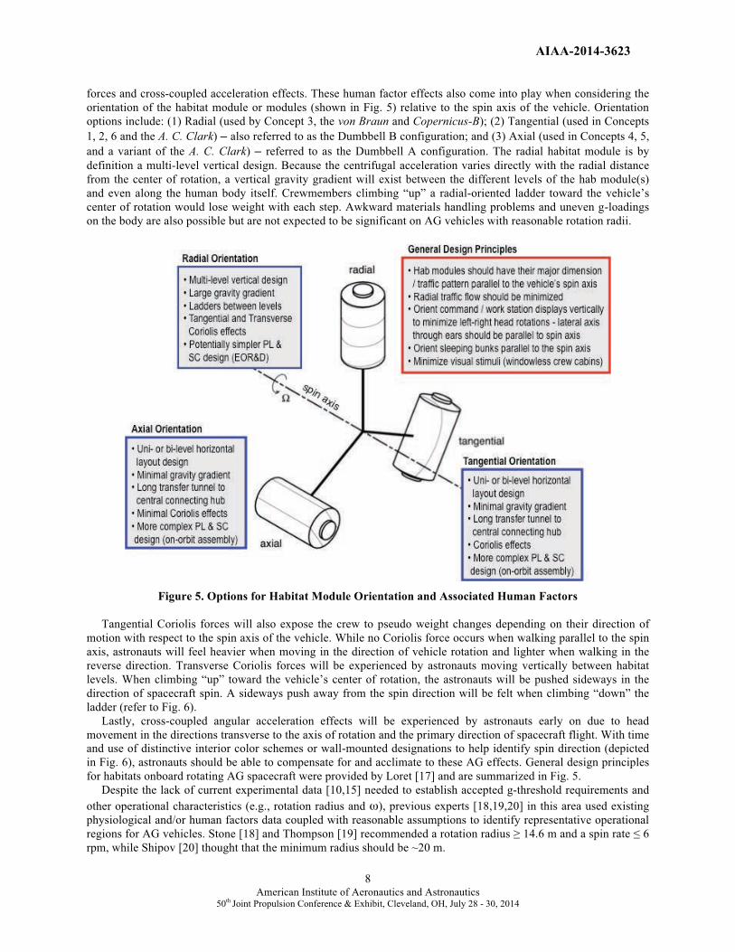
forces and cross-coupled acceleration effects. These human factor effects also come into play when considering the
orientation of the habitat module or modules (shown in Fig. 5) relative to the spin axis of the vehicle. Orientation
options include: (1) Radial (used by Concept 3, the von Braun and Copernicus-B); (2) Tangential (used in Concepts
1, 2, 6 and the A. C. Clark) – also referred to as the Dumbbell B configuration; and (3) Axial (used in Concepts 4, 5,
and a variant of the A. C. Clark) – referred to as the Dumbbell A configuration. The radial habitat module is by
definition a multi-level vertical design. Because the centrifugal acceleration varies directly with the radial distance
from the center of rotation, a vertical gravity gradient will exist between the different levels of the hab module(s)
and even along the human body itself. Crewmembers climbing “up” a radial-oriented ladder toward the vehicle’s
center of rotation would lose weight with each step. Awkward materials handling problems and uneven g-loadings
on the body are also possible but are not expected to be significant on AG vehicles with reasonable rotation radii.
Figure 5. Options for Habitat Module Orientation and Associated Human Factors
Tangential Coriolis forces will also expose the crew to pseudo weight changes depending on their direction of
motion with respect to the spin axis of the vehicle. While no Coriolis force occurs when walking parallel to the spin
axis, astronauts will feel heavier when moving in the direction of vehicle rotation and lighter when walking in the
reverse direction. Transverse Coriolis forces will be experienced by astronauts moving vertically between habitat
levels. When climbing “up” toward the vehicle’s center of rotation, the astronauts will be pushed sideways in the
direction of spacecraft spin. A sideways push away from the spin direction will be felt when climbing “down” the
ladder (refer to Fig. 6).
Lastly, cross-coupled angular acceleration effects will be experienced by astronauts early on due to head
movement in the directions transverse to the axis of rotation and the primary direction of spacecraft flight. With time
and use of distinctive interior color schemes or wall-mounted designations to help identify spin direction (depicted
in Fig. 6), astronauts should be able to compensate for and acclimate to these AG effects. General design principles
for habitats onboard rotating AG spacecraft were provided by Loret [17] and are summarized in Fig. 5.
Despite the lack of current experimental data [10,15] needed to establish accepted g-threshold requirements and
other operational characteristics (e.g., rotation radius and �), previous experts [18,19,20] in this area used existing
physiological and/or human factors data coupled with reasonable assumptions to identify representative operational
regions for AG vehicles. Stone [18] and Thompson [19] recommended a rotation radius � 14.6 m and a spin rate � 6
rpm, while Shipov [20] thought that the minimum radius should be ~20 m.

AIAA-2014-3623
9 American Institute of Aeronautics and Astronautics
50th Joint Propulsion Conference & Exhibit, Cleveland, OH, July 28 - 30, 2014
Figure 6. Posted Visual Cues Show Direction of Transverse Coriolis Forces When Climbing Between Levels
During the 1960’s, researchers [21,22] at the Naval Medical Research Laboratory in Pensacola, Florida used their
Slow Rotating Room (SRR) to study the acute rotation effects phenomena at rates as high as 10 rpm. Their results
indicated that a judicious restriction of head motions and progressive adaptation through stepwise increases in spin
rate (1 rpm every 2 days during 16 days of rotation) allowed most human subjects to adjust quickly to avoid the
adverse physical symptoms of higher rotation rates. “Later studies have expanded on the experience from that time
and demonstrated that complete adaptation to rotation rates as high as 10 rpm can be achieved within minutes if
repeated voluntary movements are made. Such movements were avoided in the early Pensacola studies.” [15]. The
recent AG workshop White Paper suggested expanding upon the SRR experiments by refurbishing and using the 2-
room, 52-foot diameter centrifuge at Ames Research Center [15] to help develop requirements for future rotating
vehicles. It also recommended a coordinated global effort to provide data and answers to key questions by 2022.
This would allow sufficient time to incorporate AG features into vehicle designs for use on long duration, deep
space missions in the late 2020’s – early 2030’s timeframe should they be needed.
III. NTR / BNTR System Descriptions and Performance Characteristics The NTR uses a compact fission reactor core containing 93% “enriched” Uranium (U)-235 fuel to generate 100’s
of megawatts of thermal power (MWt) required to heat the LH2 propellant to high exhaust temperatures for rocket
thrust. In an “expander cycle” Rover/NERVA-type engine (Fig. 7), high pressure LH2 flowing from either a single or
twin turbopump assembly (TPA) is split into two paths with the first cooling the engine’s nozzle, pressure vessel,
neutron reflector, and control drums, and the second path cooling the engine’s tie-tube assemblies. The flows are
then merged and the heated H2 gas is used to drive the TPAs. The hydrogen turbine exhaust is then routed back into
the reactor pressure vessel and through the internal radiation shield and core support structure before entering the
coolant channels in the reactor core’s fuel elements. Here it absorbs energy produced from the fission of U-235
atoms, is superheated to high exhaust temperatures (Tex~2550 – 2950 Kelvin (K) depending on fuel type and
uranium loading), then expanded out a high area ratio nozzle (~300:1) for thrust generation.
Controlling the NTR during its various operational phases (startup, full thrust and shutdown) is accomplished by
matching the TPA-supplied LH2 flow to the reactor power level. Twelve rotating boron carbide control drums,
located in the beryllium reflector region surrounding the reactor core, regulate the neutron population and reactor
power level over the NTR’s operational lifetime. The internal neutron and gamma radiation shield, located within
the engine’s pressure vessel, contains its own interior coolant channels. It is placed between the reactor core and key
engine components to prevent excessive radiation heating and material damage.
AIAA-2014-3623
10American Institute of Aeronautics and Astronautics
50th Joint Propulsion Conference & Exhibit, Cleveland, OH, July 28 - 30, 2014
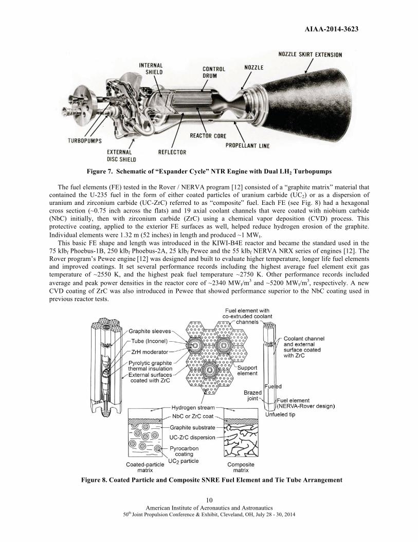
Figure 7. Schematic of “Expander Cycle” NTR Engine with Dual LH2 Turbopumps
The fuel elements (FE) tested in the Rover / NERVA program [12] consisted of a “graphite matrix” material that
contained the U-235 fuel in the form of either coated particles of uranium carbide (UC2) or as a dispersion of
uranium and zirconium carbide (UC-ZrC) referred to as “composite” fuel. Each FE (see Fig. 8) had a hexagonal
cross section (~0.75 inch across the flats) and 19 axial coolant channels that were coated with niobium carbide
(NbC) initially, then with zirconium carbide (ZrC) using a chemical vapor deposition (CVD) process. This
protective coating, applied to the exterior FE surfaces as well, helped reduce hydrogen erosion of the graphite.
Individual elements were 1.32 m (52 inches) in length and produced ~1 MWt.
This basic FE shape and length was introduced in the KIWI-B4E reactor and became the standard used in the
75 klbf Phoebus-1B, 250 klbf Phoebus-2A, 25 klbf Pewee and the 55 klbf NERVA NRX series of engines [12]. The
Rover program’s Pewee engine [12] was designed and built to evaluate higher temperature, longer life fuel elements
and improved coatings. It set several performance records including the highest average fuel element exit gas
temperature of ~2550 K, and the highest peak fuel temperature ~2750 K. Other performance records included
average and peak power densities in the reactor core of ~2340 MWt/m3 and ~5200 MWt/m
3, respectively. A new
CVD coating of ZrC was also introduced in Pewee that showed performance superior to the NbC coating used in
previous reactor tests.
Figure 8. Coated Particle and Composite SNRE Fuel Element and Tie Tube Arrangement
�

AIAA-2014-3623
11 American Institute of Aeronautics and Astronautics
50th Joint Propulsion Conference & Exhibit, Cleveland, OH, July 28 - 30, 2014
In addition to FEs, the engine reactor cores also included tie tube (TT) elements of the same hexagonal shape that
provided structural support for the FEs. A coaxial coolant tube of Inconel inside each TT supplied a source of heated
hydrogen for turbine drive power and a sleeve of zirconium hydride (ZrH) moderator material could also be
incorporated in the TTs to help raise neutron reactivity (shown in Fig. 8). In the larger size engines tested during the
Rover / NERVA programs, a “sparse” FE – TT arrangement was used with each FE having 2 adjacent TTs and 4
adjacent FEs comprising its six surrounding elements [23]. In this sparse pattern, the FE to TT ratio is ~3 to 1.
In the Small Nuclear Rocket Engine (SNRE) design developed by Los Alamos National Laboratory near the end
of Rover / NERVA [24], shorter (0.89 m / 35 inch) FEs were used so additional TTs were included in the reactor to
increase core reactivity. With the “SNRE” FE – TT pattern each FE has 3 adjacent TTs and 3 adjacent FEs
surrounding it (shown in Fig. 8) and the FE to TT ratio is ~2 to 1. An important feature common to both the sparse
and SNRE FE – TT patterns is that each tie tube provides mechanical support for six adjacent fuel elements.
Recent Monte Carlo N-Particle (MCNP) transport modeling of these thermal / epithermal spectrum reactor cores
by Schnitzler et al., [23,25,26] has shown that the SNRE design can be scaled down to even lower thrust levels (~5.3
– 7.4 klbf) or up to the 25 klbf Pewee-class engine used in Mars DRA 5.0. For low thrust engines, short length
elements (~0.89 m) and a “dense” FE – TT pattern are used consisting of parallel rows of FEs and TTs. Each FE has
4 adjacent TTs and 2 adjacent FEs surrounding it and the FE to TT ratio is ~1 to 1. By using the SNRE FE – TT
pattern and increasing the FE length from 0.89 m to 1.32 m (the same length used in the Rover program’s Pewee
engine), the U-235 fuel loading in the core can be lowered from ~0.60 to 0.25 grams/cm3 allowing the FEs to
operate at higher peak fuel temperatures (Tpeak) while still staying safely below the melt temperature for composite
fuel of ~3050 K. It also allows higher hydrogen exhaust / higher chamber inlet temperatures thereby increasing the
engine’s Isp capability. Higher Isp operation can help stretch the available LH2 propellant loading to meet mission
requirements, or in the case of an emergency to allow a safe return of the crew.
The reference NTR engine used in DRA 5.0 and this paper is a 25 klbf Pewee-class engine based on the “axial-
growth” version of the SNRE. It utilizes an expander cycle and has the following nominal performance parameters:
Tex ~2790 K, chamber pressure ~1000 psia, nozzle area ratio (NAR) ~300:1, and Isp~906 s. The LH2 flow rate is
~12.5 kg/s and the engine thrust-to-weight ratio is ~3.50. The overall engine length is ~7.01 m, which includes an
~2.16 m long, retractable radiation-cooled nozzle skirt extension. The nozzle exit diameter is ~1.87 m. The higher
chamber pressure helps to maintain reasonable nozzle dimensions at the assumed NAR. The engine’s reactor core
contains 564 FEs and 241 TTs that are 1.32 m long like those used in Pewee. The core power level and fuel matrix
power density are ~560 MWt and ~3.44 MWt / liter, respectively. The U-235 fuel loading used in the reactor FEs is
~0.25 grams / cm3
and the inventory of 93% enriched U-235 in the core is just under 37 kilograms. At this fuel
loading the engine is able to operate at a Tpeak of ~2860 K providing a temperature margin to fuel melt of ~190 K.
During enhanced operation Tpeak is raised to ~3010 K (a margin-to-melt temperature of ~40 K) and Tex to ~2940 K
resulting in an ~35 second increase in Isp to ~940 s if needed.
High temperature UC-ZrC in graphite “composite” fuel with ZrC coating is the primary fuel form used in the
Pewee-class engines. Composite FEs were first tested in the “Nuclear Furnace” element test reactor [12] and
withstood peak power densities of ~4500-5000 MWt/m3. They also demonstrated better corrosion resistance than the
standard coated particle graphite matrix fuel element used in the previous Rover/NERVA reactor tests. Composite
fuel’s improved corrosion resistance is attributed to its higher coefficient of thermal expansion that more closely
matches that of the protective ZrC coating, thereby helping to reduce coating cracking. Electrical-heated composite
fuel elements were also tested by Westinghouse in hot hydrogen at 2700 K for ~600 minutes – equivalent to ten 1-
hour cycles. At the end of Rover / NERVA program, composite fuel performance projections [27] were estimated at
~2-6 hours at full power for hydrogen exhaust temperatures of ~2500-2800 K.
As mentioned in the Introduction, the motivation for selecting NTP as the propulsion system of choice for Mars
is simple – it is a proven technology with a specific impulse that is twice that of today’s best chemical rockets.
During the Rover / NERVA programs (1955-1972), a technology readiness level (TRL~5-6) was achieved [12].
Twenty rocket reactors were designed, built and ground tested in integrated reactor / engine tests that demonstrated:
(1) a wide range of thrust levels (~25, 50, 75 and 250 klbf); (2) high temperature carbide-based nuclear fuels that
provided hydrogen exhaust temperatures up to 2550 K (achieved in Pewee); (3) sustained engine operation (over 62 minutes for a single burn achieved in the NRX-A6); as well as (4) accumulated lifetime at full-power; and (5) restart
capability (>2 hours with 28 startup and shutdown cycles achieved in the NRX-XE experimental engine) – all the
requirements needed for a human Mars mission. Just as important, NTP requires no large scale-ups in size or
performance like that required with other advanced propulsion options. Three Pewee-class engines are sufficient.

AIAA-2014-3623
12American Institute of Aeronautics and Astronautics
50th Joint Propulsion Conference & Exhibit, Cleveland, OH, July 28 - 30, 2014
Bimodal NTR Option
Besides providing high thrust at high Isp, the NTR also represents a “rich energy source” because it contains
substantially more U-235 fuel in its reactor core than is consumed during the primary propulsion maneuvers
performed in a typical Mars mission. By reconfiguring the NTR for “bimodal” operation [28] (both thrust and power
production), the BNTR can generate 10’s of kilowatts of electrical power for crew life support, high data-rate
communications, and zero-boiloff (ZBO) LH2 propellant storage using an active refrigeration system. Like the
conventional NTR, the BNTR engine’s reactor produces 100’s of MWt during the high thrust “propulsion phase”.
During the “mission coast / power generation phase,” the BNTR’s reactor continues to operate but in an “idle mode”
at greatly reduced power levels (~125 kWt to produce ~25 kWe). Energy generated in the reactor fuel assemblies is
removed using a secondary “closed” coolant loop that carries a helium-xenon (He-Xe) gas mixture to a Bratyon
cycle power conversion system.
The BNTR design selected and used in this study is the “trimodal” NTR concept engine, called TRITON [29]. It
is based on collaborative work between Pratt and Whitney, Aerojet (now Aerojet Rocketdyne), GRC and RENMAR.
The TRITON engine uses ceramic-metallic or “cermet” fuel elements consisting of uranium dioxide (UO2) in a
tungsten (W) metal matrix. This fast spectrum reactor fuel type was developed in the ANL and GE-710 nuclear
rocket programs [30,31] as a backup to the Rover/NERVA fuel. To generate electricity, each UO2 – W fuel element
in TRITON’s reactor core has integrated into it a closed loop, coaxial energy transport duct (ETD) that carries the
He-Xe coolant. The heated gas (at ~1300 K) is then routed to a 25 kWe-class BRU using a turbine-alternator-
compressor assembly that generates electricity at ~20% conversion efficiency. Waste heat is rejected to space using
a conical pumped-loop radiator mounted to the exterior of the propulsion stage thrust structure (shown in Fig. 3).
The radiator also helps remove low level decay heat power from the engines following high thrust operation.
TRITON’s third feature includes an oxygen “afterburner” nozzle that uses an oxygen-rich gas generator (GG) to
provide gasified oxygen downstream of the nozzle throat at a NAR of ~40:1. Here it mixes with reactor-heated H2
and undergoes supersonic combustion adding both mass and chemical energy to the rocket exhaust. By controlling
the “oxygen-to-hydrogen” mixture ratio, TRITON can operate over a wide range of thrust and Isp levels while the
reactor core power level remains relatively constant. A simplified schematic and key features of the TRITON engine
are shown in Figs. 9 and 10.
Figure 9. TRITON Schematic Showing Brayton Cycle and O2 Afterburner GG Flowpaths [29].
AIAA-2014-3623
13American Institute of Aeronautics and Astronautics
50th Joint Propulsion Conference & Exhibit, Cleveland, OH, July 28 - 30, 2014
The 25 klbf-class TRITON engines considered in this study use an expander cycle and have the following
performance parameters: Tex ~2700 K, chamber pressure ~1000 psia, nozzle area ratio ~300:1, Isp ~911 s and LH2
flow rate of ~12.45 kg/s. The engine thrust-to-weight (F/Weng) ratio is ~5.5 although ongoing studies [32] indicate
that a value of ~4.0 may be more appropriate. The overall engine length varies from ~6.25 to 6.5 m (depending on
FE length), which includes the ~1.93 m long, retractable radiation-cooled nozzle skirt extension. The nozzle exit
diameter is ~1.75 m.
The engine’s reactor core contains ~199 UO2 – W fuel elements with a fuel composition, by volume, of 60%
UO2, 34% W, and 6% gadolinium oxide (Gd2O3) – an oxygen stabilizer. The FE coolant channels and exterior
surfaces are also clad with a tungsten rhenium (W-Re) alloy. Each FE has a hexagonal cross section (~1.70 inches
across the flats) and 48 axial flow, hydrogen coolant channels. The length of the fuel elements can vary from ~61 to
86.4 cm (24 to 34 inches) [32]. The core power level and fuel matrix power density are ~530 MWt and ~3.52 MWt /
liter, respectively.
For a fast spectrum system, the inventory of highly enriched (93%) U-235 (HEU) mass in the core is significantly
higher. For the 25 klbf thermal spectrum Pewee-class engine discussed above, the amount of HEU is ~37 kg. By
contrast, the same thrust class engine using a variant of the “heritage” GE-710 fuel element design requires ~225 kg
of HEU [32]. An order of magnitude higher HEU inventory over that found in the Pewee-class engine is expected in
the TRITON engine due in part to the additional internal hardware (ETD) in each FE used for electrical power
generation. The fuel matrix power density used in the TRITON engine (~3.52 MWt / liter) is also the lowest of the
heritage cermet-fueled engine designs examined by Schnitzler [32] which range from ~5.40 MWt / liter for the
ANL-200 [30] to ~13.5 MWt / liter for the GE-710 [31]. If integrated multi-physics (thermal, fluid, and structural)
analyses [33] confirm that higher fuel matrix power density operation in the TRITON design is possible, it is
expected that core masses and fissile inventories could be reduced.
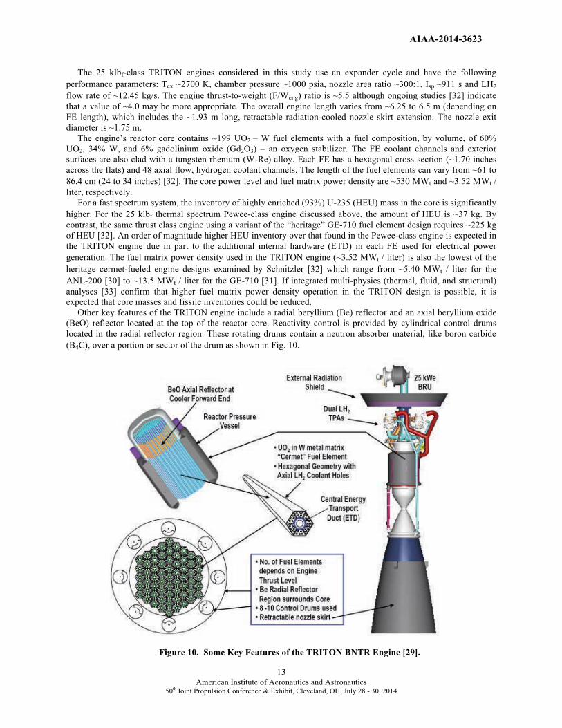
Other key features of the TRITON engine include a radial beryllium (Be) reflector and an axial beryllium oxide
(BeO) reflector located at the top of the reactor core. Reactivity control is provided by cylindrical control drums
located in the radial reflector region. These rotating drums contain a neutron absorber material, like boron carbide
(B4C), over a portion or sector of the drum as shown in Fig. 10.
Figure 10. Some Key Features of the TRITON BNTR Engine [29].

AIAA-2014-3623
14American Institute of Aeronautics and Astronautics
50th Joint Propulsion Conference & Exhibit, Cleveland, OH, July 28 - 30, 2014
IV. Mission and Transportation System Ground Rules and Assumptions
Specific mission and NTR transportation system ground rules and assumptions used in this paper are summarized
in Tables 1 and 2, respectively. Table 1 provides information about the crewed mission scenario, assumed parking
orbits at Earth and Mars, along with the �V budget for the round trip fast conjunction, crewed mission used in DRA
5.0. In addition to the large �V requirements shown for the primary propulsion maneuvers [trans-Mars injection
(TMI), Mars orbit capture (MOC) and trans-Earth injection (TEI)], smaller �V maneuvers are also needed for
rendezvous and docking (R&D) of MTV components during the LEO assembly phase, for spacecraft attitude control
during in-space transit, Mars orbital operations, and for vehicle rotation “spin-up / spin-down” maneuvers.
For the crewed mission, the outbound payload mass varies with the crew size and mission duration. For long
surface stay Mars missions, the MTV carries contingency consumables equivalent to that found on the habitat
lander. This allows the MTV to function as an orbital “safe haven” in the event of a major failure of a key surface
system. On the AG/MTV designs using BNTP, these extra consumables are stored in a single large container
attached to the rear of the TransHab module via a transfer tunnel enclosed within a short saddle truss (like that
shown in Fig 4). On the AG/MTV using NTP, two smaller containers are used and are attached to a central logistics
and docking hub located at the front of the vehicle. For the nominal surface mission, the contingency consumables
are jettisoned prior to the TEI maneuver. Other payload elements include the Orion Multi-Purpose Crew Vehicle
(MPCV). For Mars DRA 5.0 and in this analysis it is assumed that ~250 kg of samples are returned.
Table 1. Mission and Payload Ground Rules and Assumptions
y p
Mars DRA 5.0 Mission Profile: • Split mission; cargo pre-deployed to Mars before crew leaves Earth
• Cargo missions use “1-way” minimum energy trajectory
• Round trip crewed missions use “fast conjunction” trajectories
• Landing mission with long surface stay (~526 days)
• Direct return uses Orion capsule for crew recovery at mission end
Missions depart from low Earth orbit (LEO); capture
into and depart from a 24-hr elliptical Mars
orbit (EMO)
• LEO: 407 km circular
• 24-hr EMO: 250 km x 33, 793 km
“All Propulsive” Crewed Mission �V Budgets: • Earth Departure C3 ~18.40 km2/s2, �VTMI ~3.992 km/s,
arrival Vinf ~4.176 km/s, �VMOC ~1.771 km/s
• Mars Departure C3 ~14.80 km2/s2, �VTEI ~1.562 km/s
• NOTE: Gravity losses added to above Ideal �Vs
Additional �V Requirements: Advanced Material
Bipropellant Rocket (AMBR) RCS thrusters used
to perform non-primary propulsion maneuvers; also
to initiate and stop vehicle rotation during transit out
to Mars and back
• LEO R&D between orbital elements: ~15 – 100 m/s
• Coast attitude control and mid – course correction:
~15 m/s and ~50 m/s, respectively;
• Mars orbit maintenance plus R&D: ~100 m/s
• RCS propellant mass for vehicle spin-up / spin-down
determined from Eq. 5
Crewed Mission Payload Masses: Varies with crew
size, mission duration, and assumed habitat design;
consumables based on a crew consumption rate of
~2.45 kg/person/day; other possible payload elements
include a short saddle truss (SST) and transfer tunnel
with second docking module (TDM); a central logistics
module with twin long transfer tunnels and supports; an
exterior contingency consumables container(s) that can
be jettisoned prior to the TEI maneuver; and other
equipment
• Single TransHab Module: 25.0 t (minus consumables)
• SST/TDM/Container: 5.08 t / 1.76 t / 23% of stored food
• Twin “Stretch” ISS Modules: 34.0 t (minus consumables)
• Central Logistics Hub: 7.15 t
• Twin Transfer Tunnels: 2 x 1.625 t per tunnel + 2.25 t supports
• Other Equipment: 8.21 t (on ISS Modules)
• Crew (5-6) & Suits: 0.5 t – 0.6 t
• Total Consumables: 4.47 t –5.37 t (5 – 6 crew for 1-yr); with
extra consumables stored in exterior container
• Orion / MPCV: ~13.5 t
• Returned Samples: 0.25 t (Mars)
Mission Abort Strategy: • Outbound: Abort to Mars Surface
• At Mars: Abort to the orbiting AG/MTV which caries contingency
consumables onboard and provides AG environment for the crew
AIAA-2014-3623
15American Institute of Aeronautics and Astronautics
50th Joint Propulsion Conference & Exhibit, Cleveland, OH, July 28 - 30, 2014
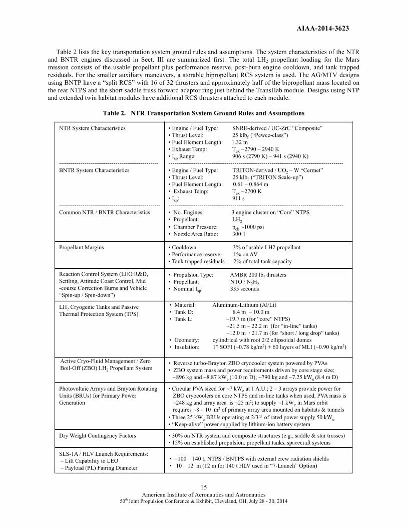
Table 2 lists the key transportation system ground rules and assumptions. The system characteristics of the NTR
and BNTR engines discussed in Sect. III are summarized first. The total LH2 propellant loading for the Mars
mission consists of the usable propellant plus performance reserve, post-burn engine cooldown, and tank trapped
residuals. For the smaller auxiliary maneuvers, a storable bipropellant RCS system is used. The AG/MTV designs
using BNTP have a “split RCS” with 16 of 32 thrusters and approximately half of the bipropellant mass located on
the rear NTPS and the short saddle truss forward adaptor ring just behind the TransHab module. Designs using NTP
and extended twin habitat modules have additional RCS thrusters attached to each module.
Table 2. NTR Transportation System Ground Rules and Assumptions Table 2. NTR Transportation System Ground Rules and Assumptions
NTR System Characteristics
---------------------------------------------------
BNTR System Characteristics
----------------------------------------------------
Common NTR / BNTR Characteristics
• Engine / Fuel Type: SNRE-derived / UC-ZrC “Composite”
• Thrust Level: 25 klbf (“Pewee-class”)
• Fuel Element Length: 1.32 m
• Exhaust Temp: Tex ~2790 – 2940 K
• Isp Range: 906 s (2790 K) – 941 s (2940 K)
------------------------------------------------------------------------------------------
• Engine / Fuel Type: TRITON-derived / UO2 – W “Cermet”
• Thrust Level: 25 klbf (“TRITON Scale-up”)
• Fuel Element Length: 0.61 – 0.864 m
• Exhaust Temp: Tex ~2700 K
• Isp: 911 s
------------------------------------------------------------------------------------------
• No. Engines: 3 engine cluster on “Core” NTPS
• Propellant: LH2
• Chamber Pressure: pch ~1000 psi
• Nozzle Area Ratio: 300:1
Propellant Margins • Cooldown: 3% of usable LH2 propellant
• Performance reserve: 1% on �V
• Tank trapped residuals: 2% of total tank capacity
Reaction Control System (LEO R&D,
Settling, Attitude Coast Control, Mid
-course Correction Burns and Vehicle
“Spin-up / Spin-down”)
• Propulsion Type: AMBR 200 lbf thrusters
• Propellant: NTO / N2H2
• Nominal Isp: 335 seconds
LH2 Cryogenic Tanks and Passive
Thermal Protection System (TPS)
• Material: Aluminum-Lithium (Al/Li)
• Tank D: 8.4 m – 10.0 m
• Tank L: ~19.7 m (for “core” NTPS)
~21.5 m – 22.2 m (for “in-line” tanks)
~12.0 m / 21.7 m (for “short / long drop” tanks)
• Geometry: cylindrical with root 2/2 ellipsoidal domes
• Insulation: 1” SOFI (~0.78 kg/m2) + 60 layers of MLI (~0.90 kg/m2)
Active Cryo-Fluid Management / Zero
Boil-Off (ZBO) LH2 Propellant System • Reverse turbo-Brayton ZBO cryocooler system powered by PVAs
• ZBO system mass and power requirements driven by core stage size;
~896 kg and ~8.87 kWe (10.0 m D); ~790 kg and ~7.25 kWe (8.4 m D)
Photovoltaic Arrays and Brayton Rotating
Units (BRUs) for Primary Power
Generation
• Circular PVA sized for ~7 kWe at 1 A.U.; 2 – 3 arrays provide power for
ZBO cryocoolers on core NTPS and in-line tanks when used, PVA mass is
~248 kg and array area is ~25 m2; to supply ~1 kWe in Mars orbit
requires ~8 – 10 m2 of primary array area mounted on habitats & tunnels
• Three 25 kWe BRUs operating at 2/3rd of rated power supply 50 kWe • “Keep-alive” power supplied by lithium-ion battery system
Dry Weight Contingency Factors • 30% on NTR system and composite structures (e.g., saddle & star trusses)
• 15% on established propulsion, propellant tanks, spacecraft systems
SLS-1A / HLV Launch Requirements:
– Lift Capability to LEO
– Payload (PL) Fairing Diameter
• ~100 – 140 t; NTPS / BNTPS with external crew radiation shields
• 10 – 12 m (12 m for 140 t HLV used in “7-Launch” Option)

AIAA-2014-3623
16 American Institute of Aeronautics and Astronautics
50th Joint Propulsion Conference & Exhibit, Cleveland, OH, July 28 - 30, 2014
The LH2 propellant used during the crewed Mars mission is stored in the same “state-of-the-art” Al/Li LH2
propellant tanks being developed for the SLS, the Block 1A upgrade, and Block II HLV that will support future
human exploration missions. For this analysis, tank sizing assumes a 30 psi ullage pressure, 5-g axial / 2.5-g lateral
launch loads, and a safety factor of 1.5. A 3% ullage factor is also assumed. All tanks use a combination foam /
multilayer insulation (MLI) system for passive thermal protection. A zero boil-off (ZBO) "reverse turbo-Brayton”
cryocooler system is used on both the core NTPS and bimodal NTPS (BNTPS) and in-line LH2 tanks (where
required) to eliminate boil-off during LEO assembly and the remainder of the mission. The propellant tank heat load
is largest in LEO and sizes the ZBO cryocooler systems. Two ~7 kWe Mega-flex photovoltaic arrays, on both the
NTPS and in-line tank elements, provide the power needed to run their cryocoolers with margin to spare.
For the AG/MTV designs using NTP, the primary electrical power for the crewed PL and its key subsystems is
supplied by PVAs mounted to either the twin habitat modules and their access tunnels, or to the habitat module’s
support structure (described in more detail in Sect. VIII). Because of the decreased solar radiation (~486 W/m2) at
Mars, array areas can become quite large (~8 – 10 m2/kWe) depending on the crew size and electrical power needs at
Mars. For the AG/MTV designs using BNTP, the engines and their BRUs supply the power needs of the vehicle.
Table 2 also provides the assumed “dry weight contingency” (DWC) factors, along with the SLS-1A / HLV lift
and payload fairing size requirements. A 30% DWC is used on the NTR system and advanced composite structures
(e.g., stage adaptors, trusses) and 15% on heritage systems (e.g., Al/Li tanks, RCS, etc.). The crewed MTV’s NTPS
and payload element drive the SLS-1A / HLV lift capability and fairing size, respectively. For the “7-Launch” Mars
DRA 5.0 option [14], the optimum tank diameter (D) and mass for the NTPS was 10 m and ~140 t, respectively. The
crewed PL element included the “packaged” TransHab module with its PVA power system, the short saddle truss
(SST), consumables container, and a transfer tunnel with secondary docking module (TDM) shown in Figs 4 and 12.
The PL envelope’s D was ~11 m (the saddle truss outer dimension) and its length (L) was ~24.9 m (~33.8 m if the
Orion MPCV is included as part of the launched PL element [14]), necessitating a large 12 m D fairing. In this
study, 8.4 m D propellant tanks are also used which are compatible with a 10 m D fairing. As before, it is the mass
of the NTPS and bimodal NTPS that drives the SLS-1A / HLV lift requirements which vary from ~100 – 140 t.
V. Mars DRA 5.0: “7-Launch” NTR Mission Overview The DRA 5.0 7-Launch strategy
[14] for a Mars landing mission is illustrated in Fig. 11. It assumes a long
surface stay, split cargo / piloted mission approach. Two cargo flights pre-deploy a cargo lander to the surface and a
habitat lander into Mars orbit where it remains until the arrival of the crew on the next mission opportunity. The
cargo flights utilize “1-way” minimum energy, long transit time trajectories. Four HLV flights carried out over 90
days (~30 days between launches), deliver the required components for the two cargo vehicles. The first two
launches deliver the NTP stages each with three 25 klbf NTR engines. The next two launches deliver the cargo and
habitat lander payload elements which are enclosed within a large triconic-shaped aeroshell that functions as a
payload shroud during launch, then as an aerobrake and thermal protection system during Mars aerocapture (AC)
and subsequent entry, descent and landing (EDL) on Mars. Vehicle assembly involves Earth orbit rendezvous and
docking (R&D) between the propulsion stages and payload elements with the NTP stages functioning as the active
element in the R&D maneuver.
Once the operational functions of the orbiting habitat and surface cargo landers are verified, and the Mars Ascent
Vehicle (MAV) is supplied with ISRU-produced ascent propellant, the crewed MTV is readied and departs on the
next mission opportunity ~26 months later. The crewed 0-g MTV, Copernicus, is capable of 1-way transit times
ranging from ~150 – 220 days depending on the particular opportunity. Like the cargo MTVs, Copernicus is
assembled in LEO using Earth orbit R&D. It uses the same “common” NTPS but includes additional external
radiation shielding on each engine for crew protection during engine operation. Three HLV launches over 60 days
are used to deliver the vehicle’s key elements which include: (1) the NTPS; (2) the integrated “saddle truss” and LH2
drop tank assembly; and (3) the crewed payload. The payload element includes the TransHab module with its 6
crew, the Orion MPCV for vehicle-to-vehicle transfer and “end of mission” re-entry, a secondary T-shaped DM, a
contingency consumables container and connecting structure. Four 12.5 kWe / 125 m2 rectangular PVAs provide
~50 kWe of electrical power at Mars for crew life-support (~30 kWe), a ZBO Brayton cryocooler system (~10 kWe),
and high data- rate communications (~10 kWe) with Earth.
When assembly is completed, the Mars crew is delivered to LEO using either the MPCV and SLS or a
commercial crew launch vehicle and docks with Copernicus on its underside using the secondary DM that connects
the TransHab crew module and contingency consumables container (shown in Figs. 4 and 12). Following the TMI

AIAA-2014-3623
17American Institute of Aeronautics and Astronautics
50th Joint Propulsion Conference & Exhibit, Cleveland, OH, July 28 - 30, 2014
Figure 11. DRA 5.0 Long-Stay Mars Mission Overview: “7-Launch” NTR Strategy
maneuver, the drained LH2 drop tank, attached to the saddle truss, is jettisoned and Copernicus coasts to Mars under
0-g conditions with its four PVAs tracking the Sun. Attitude control and mid-course correction maneuvers are
provided by Copernicus’ split RCS that uses 200 lbf storable bipropellant AMBR (Advanced Material Bipropellant
Rocket) thrusters located on the rear NTPS and the short saddle truss forward adaptor ring just behind the TransHab
module. After a 180-day transit out to Mars, Copernicus performs the MOC burn then rendezvous with the orbiting
Hab lander using engine cool-down thrust and the vehicle’s RCS. After a week in Mars orbit checking out the
landing site and preparing Copernicus for autonomous operations, the crew transfers over to the lander in the MPCV
which subsequently returns and docks to the TransHab autonomously. The crew then initiates EDL near the cargo
lander and begins the surface exploration phase of the mission. After ~526 days on the surface, the crew lifts off
using the MAV and returns to Copernicus using its secondary TDM (shown in Fig. 12). Following the transfer of
the crew and samples, the MAV is jettisoned. The crew then begins a weeklong checkout and verification of all
MTV systems, jettisons the TDM and contingency consumables and performs the TEI burn to begin the journey
back to Earth. After a 180-day return trip, the crew enters the MPCV, separates from the MTV and re-enters Earth’s
atmosphere while Copernicus flies by Earth at a “sufficiently high altitude” and is disposed of into heliocentric
space. Although Copernicus was operated in an “expendable mission mode” in DRA 5.0 to reduce total IMLEO and
number of HLV launches, it can readily be modified to operate in a “reuse mode” by providing the vehicle with
additional propellant capacity as discussed elsewhere [34].
The Copernicus crewed MTV had an overall length of ~93.7 m and an IMLEO of ~336.5 t which included the
following: (1) the NTPS (~138.1 t); (2) the saddle truss and LH2 drop tank (~133.4 t); and (3) the crew payload
section (~65 t). Additional size and mass details on the Copernicus MTV are found elsewhere [34, 35].
The performance requirements on operating time and restart for Copernicus’ three 25 klbf NTR engines were
also quite reasonable. For the round trip mission, there were 4 primary burns (3 restarts) that used ~178.4 t of LH2
propellant. With ~75 klbf of total thrust and a Isp of ~906 s, the total engine burn time for the mission was ~79.2
minutes (~55 minutes for the “2-perigee burn” TMI maneuver, ~14.5 minutes for MOC, and ~9.7 minutes for TEI),
well under the ~2 hour accumulated engine burn time and 27 restarts demonstrated by the NERVA eXperimental
Engine – the NRX-XE [12].
Crewed �0-g MTV�
MAV ascent �to orbit�
Crew: 180 days �back to Earth�
Cargo: 283�days to �Mars�
4 Cargo HLV �Launches�
Crew Launch�
~26�months�
~30�months�
1�
2�
4�
6�
7�
9�
11�
13�
Crew: Use Orion MPCV �to transfer to Hab Lander;�
then EDL on Mars�
Orion direct Earth return�
14�
3�
Habitat Lander AC�into Mars Orbit�
5�
ISRU / propellant�production for MAV�
10� ~526 days on Mars�
AC / EDL of MDAV / Cargo Lander�
Crew: Jettison DM �& contingency�consumables �prior to TEI�
12�
3 HLV Cargo Launches�
Cargo�MTVs�
Crew: Jettison TMI�drop tank; 180 day �transfer out to Mars�
8�
SLS / HLV Mars Requirements:
• ~140 t to LEO (407 km circ)
• PL Envelope: 11 m D x 33.8 m L

AIAA-2014-3623
18American Institute of Aeronautics and Astronautics
50th Joint Propulsion Conference & Exhibit, Cleveland, OH, July 28 - 30, 2014
Figure 12. Copernicus’ TDM Provides Access to the MPCV and MAV during the Mission
VI. Copernicus-B: An AG/MTV Design Option for Mars DRA 5.0 As mentioned in the Introduction, AG vehicles were ground ruled out of the DRA 5.0 study. Although sufficient
contingency consumables were carried onboard to sustain the crew for up to 540 days in Mars orbit, crew fitness
onboard Copernicus after ~2.5 years in a weightless environment was questionable. An AG version of Copernicus, called Copernicus-B, was developed by GRC shortly after the DRA 5.0 study was completed to address this
deficiency. The Copernicus-B spacecraft is larger than its DRM 4.0 predecessor, the von Braun, due to key
transportation system, mission and payload changes implemented between DRM 4.0 and DRA 5.0 [14]. These
changes included the use of Al/Li instead of composite propellant tanks, higher DWC factors, slightly higher Mars
mission �Vs over the timeframe of interest, an ~37.5 % increase in the TransHab mass (from ~20 to 27.5 t), a 100%
increase in the reentry crew capsule mass (from ~5 to 10 t), plus an ~400% increase in the AC/EDL aeroshell mass
(from ~10 to 40 t) used on each of the cargo flights. As a result of these increases, larger diameter propellant tanks
(from 7.4 m to 8.4 and 10 m) and higher thrust NTR engines (from 15 to 25 klbf) were required.
Like its 0-g counterpart, Copernicus-B is an in-line configuration that uses Earth orbit R&D to simplify vehicle
assembly (shown in Fig. 13). Three HLV launches over 60 days are again used to deliver the vehicle’s key
components to LEO which include: (1) the BNTPS; (2) the integrated “saddle truss” and LH2 drop tank assembly;
and (3) the crewed payload. The cylindrical adaptor interfaces of the elements contain a docking mechanism, as well
as all electrical and fluid connections to allow autonomous mating of the three elements in LEO. As with the NTPS,
the BNTPS also includes additional external radiation shielding on each engine for crew protection during engine
operation. The payload element includes the TransHab module with its 6 crew, the Orion MPCV, the TDM and
contingency consumables container, plus the short saddle truss that connects the PL to the BNTPS. The inflatable
TransHab module on Copernicus-B has three vertical levels oriented radial to the vehicle’s spin axis (shown in Figs.
5 and 6). Its structural mass has also been increased by ~1 t to accommodate the centrifugal forces it experiences
during AG operation.
A noticeable difference between Copernicus and Copernicus-B is the absence of the four large and heavy (~3.5 t)
PVAs. As mentioned previously, Copernicus-B uses its TRITON engines and a Brayton power conversion system to
produce the 50 kWe of total electrical power needed to run the spacecraft. Each engine has its own 25 kWe BRU that
is operated at 2/3rd
of rated power (~17 kWe) under normal operating continues. If an engine or BRU were lost, the
remaining two units are ramped up to 25 kWe to produce the required power level for the vehicle. The electrical
power generated by the Brayton system is routed to the PL section via redundant electrical conduits attached to the
sides of the long and short saddle truss assemblies. Another difference is the addition of two foldout radiator panels
on the short saddle truss assembly used to radiate waste heat from the TransHab subsystems. Both the electrical
conduits and foldout radiators are shown in Figs 13, 14 and 15.
MAV R&D
with MTV
Crew Delivery
MPCV
AIAA-2014-3623
19American Institute of Aeronautics and Astronautics
50th Joint Propulsion Conference & Exhibit, Cleveland, OH, July 28 - 30, 2014
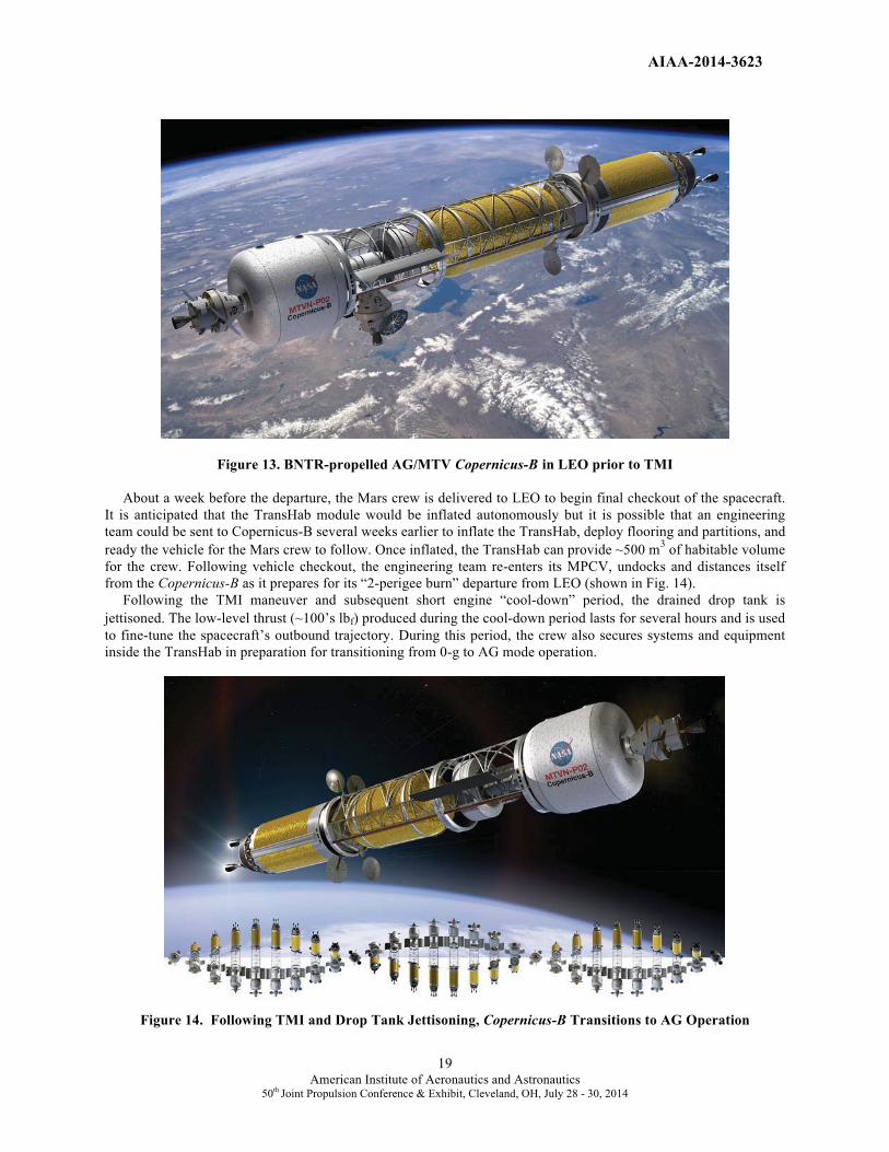
Figure 13. BNTR-propelled AG/MTV Copernicus-B in LEO prior to TMI
About a week before the departure, the Mars crew is delivered to LEO to begin final checkout of the spacecraft.
It is anticipated that the TransHab module would be inflated autonomously but it is possible that an engineering
team could be sent to Copernicus-B several weeks earlier to inflate the TransHab, deploy flooring and partitions, and
ready the vehicle for the Mars crew to follow. Once inflated, the TransHab can provide ~500 m3 of habitable volume
for the crew. Following vehicle checkout, the engineering team re-enters its MPCV, undocks and distances itself
from the Copernicus-B as it prepares for its “2-perigee burn” departure from LEO (shown in Fig. 14).
Following the TMI maneuver and subsequent short engine “cool-down” period, the drained drop tank is
jettisoned. The low-level thrust (~100’s lbf) produced during the cool-down period lasts for several hours and is used
to fine-tune the spacecraft’s outbound trajectory. During this period, the crew also secures systems and equipment
inside the TransHab in preparation for transitioning from 0-g to AG mode operation.
Figure 14. Following TMI and Drop Tank Jettisoning, Copernicus-B Transitions to AG Operation
AIAA-2014-3623
20 American Institute of Aeronautics and Astronautics
50th Joint Propulsion Conference & Exhibit, Cleveland, OH, July 28 - 30, 2014
During the initial 150-day transit out to Mars, 1-g is provided for the crew to maintain a high level of fitness. To
generate this AG environment, Copernicus-B uses its forward and rear RCS to initiate vehicle rotation about its
center-of-mass (CM) which is located ~3.0 m forward of the BNTPS. The mass of the BNTPS and its remaining
~59.0 t of LH2 propellant is counterbalanced by the masses of the TransHab, Orion/MPCV, contingency
consumables, the TDM, and the short saddle truss. With a rotation radius of ~35.2 m, the required rotation rate (ω)
is ~5 rpm. Approximately 30 days out from Mars, vehicle rotation is stopped and a final course correction burn is
performed. Afterwards, vehicle rotation is again initiated but this time Copernicus-B’s spin rate is slowed to ~3.1
rpm to generate a centrifugal acceleration in the middle of the TransHab of ~0.38-g – equivalent to the Mars gravity
field of ~3.72 m/s2. This is done to help the crew adjust to and train for operations on the Martian surface. On final
approach to Mars, the RCS is again used to terminate vehicle rotation and orient the spacecraft for its MOC burn.
The RCS propellant mass used for spin-up / spin-down and MCC maneuvers during the outbound transit is ~2.48 t.
Previous and recent simulations of NTP vehicle thrust vector control (TVC) and attitude control performed by
Ensworth [36] indicate that a combination of TVC and RCS can be used to maintain stable attitudes and steer a NTP
vehicle at low thrust levels following engine cool-down. They also verify that vehicle rotation about the axis of
maximum mass moment of inertia is most stable and requires the least control (and RCS propellant) to counteract
disturbing effects such as vehicle flexibility, propellant slosh, and astronaut movements. Estimates of RCS
propellant usage from Ensworth’s analyses are also consistent with estimates based on theoretical calculations of the
vehicle’s mass moment of inertia used in this paper. Lastly, the impact of propellant slosh was not found to be much
of an issue since once vehicle rotation starts the gravity field tends to keep the fluids in place.
Following capture at Mars, the crew rendezvous with the orbiting hab lander, transfers and descends to the
surface. Should “abort conditions” arise with either the hab lander or a major surface system, Copernicus-B is now
available to provide the crew with shelter, life support, contingency consumables, abundant power for high data rate
communications with Earth, plus an AG environment to maintain their health and fitness. An extra spin-up/spin-
down cycle is included in all vehicle mass estimates. At the end of the surface stay, the crew lifts off in the MAV
with its samples and returns to the Copernicus-B. After verification and checkout of all spacecraft systems, the crew
jettisons the MAV, then its contingency consumables and TDM, performs the TEI burn, and begins the trip home.
On the inbound transfer, the Copernicus-B starts off with an AG environment equivalent to that of Mars. After
jettisoning mass in Mars orbit and propellant performing the TEI burn, Copernicus-B’s CM moves backward to
~32.7 m or just in front of the BNTPS. With this rotation radius, the required rotation rate to generate a centrifugal
acceleration of ~0.38-g is ~3.2 rpm. After the first month, the rotation rate is increased gradually as is the g-loading
on the crew by ~0.124-g per month over the next 4 months – from ~0.504-g to ~0.876-g. Approximately 30 days out
from Earth, vehicle rotation is again stopped and a final course correction burn is performed. When vehicle rotation
resumes, it is at a higher rate of ~5.2 rpm to achieve an AG level of 1-g to help the crew readapt to Earth’s gravity
during the final month of the mission. The mission draws to a close during the final approach to Earth. Following
vehicle spin-down, the crew enters the MPCV, separates from the Copernicus-B and reenters the atmosphere while
Copernicus-B flies past Earth at a “safe distance” and is disposed of into heliocentric space. The RCS propellant
mass used for spin-up / spin-down and final course correction maneuvers during the inbound transit is ~1.76 t.
Copernicus-B’s Design Features and Characteristics The Copernicus-B spacecraft has an overall length of ~83.9 m (Fig. 15) and an IMLEO of ~332.7 t. Included are
(1) the BNTPS (~135 t); (2) the saddle truss and LH2 drop tank (~130.3 t); and (3) the crew payload section (~67.4).
The BNTPS uses a three-engine cluster of 25 klbf TRITON BNTR engines and also carries additional external
radiation shield mass (~6 t) for crew protection. The BNTPS uses an Al/Li LH2 tank size which has a diameter (D)
and length (L) of 10 m D x 19.7 m L. The LH2 tank has a propellant capacity of ~87.2 t. The BNTPS also carries
avionics, RCS and propellant, auxiliary battery and PVA power, docking and a reverse turbo-Brayton ZBO
refrigeration system located in the forward cylindrical adaptor section. To remove ~78 watts of heat penetrating the
60 layer MLI system in LEO (where the highest tank heat flux occurs), the 2-stage cryocooler system requires ~8.9
kWe for its operation. Twin circular Mega-flex PVAs on the BNTPS provide the electrical power for the ZBO
system in LEO until the Copernicus-B’s Brayton power system is brought on line prior to the TMI maneuver. At the
aft end of the BNTPS, a conical extension of the stage thrust structure provides support for a “common”, one-sided,
pumped-loop heat rejection radiator system. Enclosed within this ~71 m2
conical radiator are three 25 kWe BRUs
(one for each TRITON engine) that operate at ~2/3rd
of rated capacity and provide system redundancy. The total
mass of the Brayton power system and its radiator is estimated to be ~1350 kg. The turbine inlet temperature of the
He-Xe working gas is ~1300 K and the total system specific mass is ~27 kg/kWe.

AIAA-2014-3623
21American Institute of Aeronautics and Astronautics
50th Joint Propulsion Conference & Exhibit, Cleveland, OH, July 28 - 30, 2014
Figure 15. Key Features and Component Lengths of the Copernicus-B AG/MTV
Copernicus-B’s second major component is its saddle truss and LH2 drop tank assembly. The saddle truss is a
rigid, spine-like composite structure that wraps around the upper half of the LH2 drop tank and connects the BNTPS
to the forward payload section. It is ~26.5 m long and has a mass of ~13.1 t including docking and electrical
conduits. The saddle truss is open underneath allowing the drained LH2 drop tank to be jettisoned after the TMI burn
is completed. The ~21.7 m long LH2 drop tank has a mass of ~19.7 t and a propellant capacity of ~97.5 t. If the
F/Weng ratio for the TRITON engines decreases from ~5.5 to 4.0, the drop tank length and propellant capacity
increase to ~23.1 m and ~104.8 t, respectively. The saddle truss length and IMLEO also increase to ~27.9 m and
~346 t.
Copernicus-B’s third and final component is its payload that includes the TransHab and crew, the short saddle
truss, the TDM, consumables container, and the Orion MPCV. The total crewed payload mass at TMI is ~67.4 t
consisting of the following: (1) TransHab and 6 crew (~25.6 t); (2) short saddle truss with foldout panel radiators
(~5.1 t); (3) TDM (~2.8 t); (4) contingency consumables and jettisonable container (~9.8 t); (5) transit consumables
(~5.3 t); (6) MPCV (~13.5 t); and (7) forward RCS and propellant (~5.3 t). Copernicus-B’s total RCS propellant
loading is ~10.8 t with the “post-TMI” RCS propellant load (5.4 t) split between the BNTPS and the short saddle
truss forward cylindrical adaptor ring.
The requirements on total operating time, number of restarts and fuel burn-up for Copernicus-B’s three 25 klbf
TRITON engines are considered quite reasonable. For the round trip mission, there are 4 primary burns (3 restarts)
that use ~173.6 t of LH2 propellant. With ~75 klbf of total thrust and a Isp of ~911 s, the total engine burn time for
the mission is ~77.5 minutes (~43.5 and 10.1 minutes, respectively for the “2-perigee burn” TMI maneuver, ~14.3
minutes for MOC, and ~9.5 minutes for TEI), well under the ~2 hour accumulated engine burn time and 27 restarts
demonstrated by the NERVA NRX-XE.
Burn-up of U-235 fuel in each TRITON engine is also very low due in large part to the much higher inventory of
U-235 fuel (� 370 kg) that exists in each engine. Assuming ~1.2 grams consumed per megawatt-day of operation,
~34 grams (~0.009%) are consumed during the “propulsion mode” and ~92 grams (~0.025%) are consumed during
the “power mode”. The power mode burn-up estimate assumes 20% efficient Brayton power conversion and three
TRITON engines operating at ~0.085 MWt for the 900 days to provide 50 kWe of electrical power continuously.
25.2 m
26.5 m
11.7 m
BNTR “Core” Propulsion Stage with extendable nozzles (~2.2 m)
Long “Saddle Truss” Short “Saddle Truss” and
T-Shaped Docking Module
Engineering Team MPCV
3 – 25 klbf TRITON Engines
Forward Adaptor and Cryocooler Radiator
TransHab
Conical Radiator encloses 3 – 25 kWe BRUs
Crew Delivery
MPCV
Top Down
View Foldout Radiator Panels
Port Side
Elevation View
Contingency Consumables
Rotatable Comm Antennas (2)
Megaflex PVAs
RCS
RCS
10 m
32.2 m
83.9 m
13.5 m
LH2 Drop Tank
Electrical Conduits to Forward PL
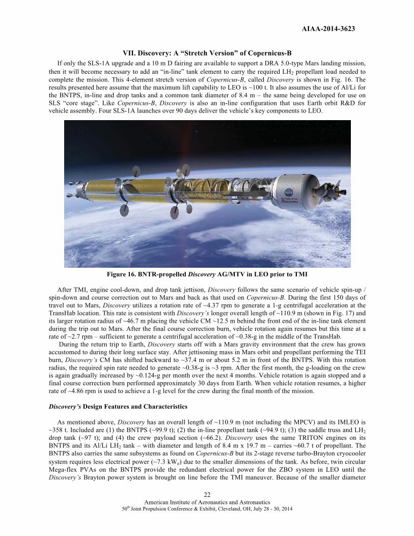
AIAA-2014-3623
22American Institute of Aeronautics and Astronautics
50th Joint Propulsion Conference & Exhibit, Cleveland, OH, July 28 - 30, 2014
VII. Discovery: A “Stretch Version” of Copernicus-B If only the SLS-1A upgrade and a 10 m D fairing are available to support a DRA 5.0-type Mars landing mission,
then it will become necessary to add an “in-line” tank element to carry the required LH2 propellant load needed to
complete the mission. This 4-element stretch version of Copernicus-B, called Discovery is shown in Fig. 16. The
results presented here assume that the maximum lift capability to LEO is ~100 t. It also assumes the use of Al/Li for
the BNTPS, in-line and drop tanks and a common tank diameter of 8.4 m – the same being developed for use on
SLS “core stage”. Like Copernicus-B, Discovery is also an in-line configuration that uses Earth orbit R&D for
vehicle assembly. Four SLS-1A launches over 90 days deliver the vehicle’s key components to LEO.
Figure 16. BNTR-propelled Discovery AG/MTV in LEO prior to TMI
After TMI, engine cool-down, and drop tank jettison, Discovery follows the same scenario of vehicle spin-up /
spin-down and course correction out to Mars and back as that used on Copernicus-B. During the first 150 days of
travel out to Mars, Discovery utilizes a rotation rate of ~4.37 rpm to generate a 1-g centrifugal acceleration at the
TransHab location. This rate is consistent with Discovery’s longer overall length of ~110.9 m (shown in Fig. 17) and
its larger rotation radius of ~46.7 m placing the vehicle CM ~12.5 m behind the front end of the in-line tank element
during the trip out to Mars. After the final course correction burn, vehicle rotation again resumes but this time at a
rate of ~2.7 rpm – sufficient to generate a centrifugal acceleration of ~0.38-g in the middle of the TransHab.
During the return trip to Earth, Discovery starts off with a Mars gravity environment that the crew has grown
accustomed to during their long surface stay. After jettisoning mass in Mars orbit and propellant performing the TEI
burn, Discovery’s CM has shifted backward to ~37.4 m or about 5.2 m in front of the BNTPS. With this rotation
radius, the required spin rate needed to generate ~0.38-g is ~3 rpm. After the first month, the g-loading on the crew
is again gradually increased by ~0.124-g per month over the next 4 months. Vehicle rotation is again stopped and a
final course correction burn performed approximately 30 days from Earth. When vehicle rotation resumes, a higher
rate of ~4.86 rpm is used to achieve a 1-g level for the crew during the final month of the mission.
Discovery’s Design Features and Characteristics
As mentioned above, Discovery has an overall length of ~110.9 m (not including the MPCV) and its IMLEO is
~358 t. Included are (1) the BNTPS (~99.9 t); (2) the in-line propellant tank (~94.9 t); (3) the saddle truss and LH2
drop tank (~97 t); and (4) the crew payload section (~66.2). Discovery uses the same TRITON engines on its
BNTPS and its Al/Li LH2 tank – with diameter and length of 8.4 m x 19.7 m – carries ~60.7 t of propellant. The
BNTPS also carries the same subsystems as found on Copernicus-B but its 2-stage reverse turbo-Brayton cryocooler
system requires less electrical power (~7.3 kWe) due to the smaller dimensions of the tank. As before, twin circular
Mega-flex PVAs on the BNTPS provide the redundant electrical power for the ZBO system in LEO until the
Discovery’s Brayton power system is brought on line before the TMI maneuver. Because of the smaller diameter
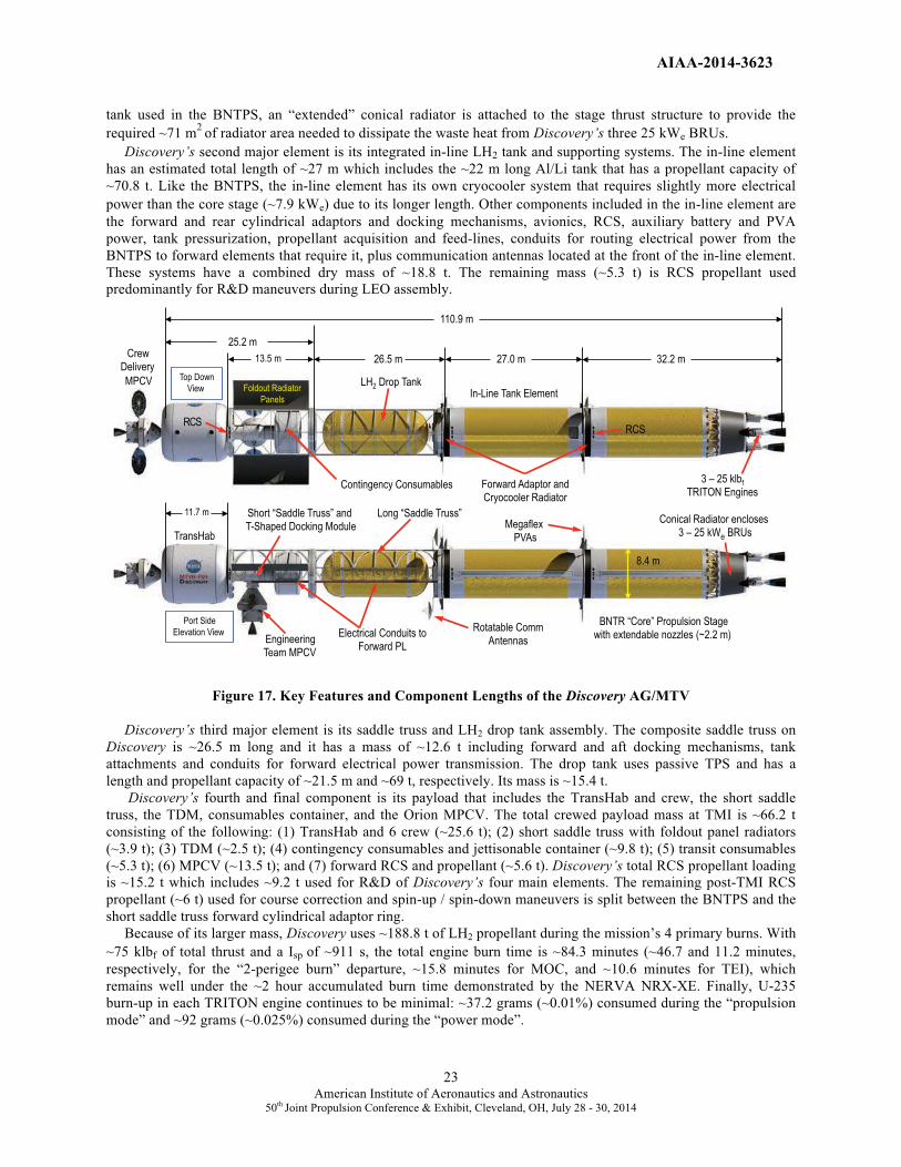
AIAA-2014-3623
23American Institute of Aeronautics and Astronautics
50th Joint Propulsion Conference & Exhibit, Cleveland, OH, July 28 - 30, 2014
tank used in the BNTPS, an “extended” conical radiator is attached to the stage thrust structure to provide the
required ~71 m2
of radiator area needed to dissipate the waste heat from Discovery’s three 25 kWe BRUs.
Discovery’s second major element is its integrated in-line LH2 tank and supporting systems. The in-line element
has an estimated total length of ~27 m which includes the ~22 m long Al/Li tank that has a propellant capacity of
~70.8 t. Like the BNTPS, the in-line element has its own cryocooler system that requires slightly more electrical
power than the core stage (~7.9 kWe) due to its longer length. Other components included in the in-line element are
the forward and rear cylindrical adaptors and docking mechanisms, avionics, RCS, auxiliary battery and PVA
power, tank pressurization, propellant acquisition and feed-lines, conduits for routing electrical power from the
BNTPS to forward elements that require it, plus communication antennas located at the front of the in-line element.
These systems have a combined dry mass of ~18.8 t. The remaining mass (~5.3 t) is RCS propellant used
predominantly for R&D maneuvers during LEO assembly.
Figure 17. Key Features and Component Lengths of the Discovery AG/MTV
Discovery’s third major element is its saddle truss and LH2 drop tank assembly. The composite saddle truss on
Discovery is ~26.5 m long and it has a mass of ~12.6 t including forward and aft docking mechanisms, tank
attachments and conduits for forward electrical power transmission. The drop tank uses passive TPS and has a
length and propellant capacity of ~21.5 m and ~69 t, respectively. Its mass is ~15.4 t.
Discovery’s fourth and final component is its payload that includes the TransHab and crew, the short saddle
truss, the TDM, consumables container, and the Orion MPCV. The total crewed payload mass at TMI is ~66.2 t
consisting of the following: (1) TransHab and 6 crew (~25.6 t); (2) short saddle truss with foldout panel radiators
(~3.9 t); (3) TDM (~2.5 t); (4) contingency consumables and jettisonable container (~9.8 t); (5) transit consumables
(~5.3 t); (6) MPCV (~13.5 t); and (7) forward RCS and propellant (~5.6 t). Discovery’s total RCS propellant loading
is ~15.2 t which includes ~9.2 t used for R&D of Discovery’s four main elements. The remaining post-TMI RCS
propellant (~6 t) used for course correction and spin-up / spin-down maneuvers is split between the BNTPS and the
short saddle truss forward cylindrical adaptor ring.
Because of its larger mass, Discovery uses ~188.8 t of LH2 propellant during the mission’s 4 primary burns. With
~75 klbf of total thrust and a Isp of ~911 s, the total engine burn time is ~84.3 minutes (~46.7 and 11.2 minutes,
respectively, for the “2-perigee burn” departure, ~15.8 minutes for MOC, and ~10.6 minutes for TEI), which
remains well under the ~2 hour accumulated burn time demonstrated by the NERVA NRX-XE. Finally, U-235
burn-up in each TRITON engine continues to be minimal: ~37.2 grams (~0.01%) consumed during the “propulsion
mode” and ~92 grams (~0.025%) consumed during the “power mode”.
25.2 m
26.5 m
11.7 m
BNTR “Core” Propulsion Stage with extendable nozzles (~2.2 m)
Long “Saddle Truss” Short “Saddle Truss” and T-Shaped Docking Module
Engineering Team MPCV
3 – 25 klbf TRITON Engines
Forward Adaptor and Cryocooler Radiator
TransHab
Conical Radiator encloses 3 – 25 kWe BRUs
Crew Delivery
MPCV Top Down
View Foldout Radiator
Panels
Port Side
Elevation View
Contingency Consumables
Rotatable Comm Antennas
Megaflex PVAs
RCS RCS
8.4 m
32.2 m
110.9 m
13.5 m
LH2 Drop Tank
Electrical Conduits to Forward PL
27.0 m
In-Line Tank Element

AIAA-2014-3623
24American Institute of Aeronautics and Astronautics
50th Joint Propulsion Conference & Exhibit, Cleveland, OH, July 28 - 30, 2014
VIII. A.C. Clark – AG/MTV Using Conventional NTP and PVA Auxiliary Power
While the long, linear configuration of the Copernicus-B and Discovery spacecraft are naturally compatible with
AG operation, the BNTR is considered to be a “second generation” engine system requiring additional engineering
features in their design like the TRITON engine’s ETD. Fast spectrum cermet-fueled engines also require
substantially more HEU (~5 –10 times) in their cores than do the thermal / epithermal spectrum NTR systems.
Similarly, it may be difficult to use the closed, coaxial tie-tubes in the NERVA-derived composite-fueled engines as
a substitute for the TRITON engine’s ETD because of the tie-tube’s lower operating temperatures. Bimodal engines
are not the only option for AG spacecraft. Indeed, it is highly likely that initial AG spacecraft will use conventional
NTP along with PVAs for auxiliary power. With its high Isp, NTP can more readily accommodate the heavier
payload mass and increased RCS propellant loading associated with AG operation. They can also enable shorter
transit times to and from Mars thereby reducing the crew’s exposure to galactic cosmic radiation and solar flares.
The AG vehicle design discussed in this section is variation of the Concept 6 configuration [8] discussed in the
Introduction. Called the A.C. Clark and depicted in Fig. 18, it carries twin cylindrical SSF-type habitation modules
whose long axes are oriented perpendicular to the longitudinal spin axis of the MTV – referred to as the Dumbbell B
configuration. Its other main components include the NTPS, an in-line tank and a 4-sided, concave-shaped “star
truss” which has attached to it four LH2 drop tanks. Like Copernicus, the NTPS uses three 25 klbf composite fuel
Pewee-class engines.
Figure 18. NTR-propelled AG/MTV – the A.C. Clark in LEO prior to TMI
The 4.6 m diameter habitat modules are connected to an octagonal-shaped central operations hub located at the
front of the Clark via two pressurized tunnels, each ~11.5 meters in length. The operations hub is ~6.4 m across the
flats and the access tunnels have outside / inside diameter of ~1.5 m /1.2 m, respectively, allowing traverse by two
shirt-sleeve astronauts, or one suited astronaut at a time. Besides ladders, the pressurized tunnels also include
electrical interconnect cabling plus a ventilation system including fans, scrubbers and ducts. The twin habitation
modules, attached to the top and bottom of the operations hub, carry all the necessary subsystems to support a 5-
person crew (the same number transported in Concept 6). Nominally, the habitats accommodate 2 to 3
crewmembers, but each has excess capacity built in so that either can serve as a safe haven for the entire crew in
case of an emergency. Each hab module also has its own docking port and dish antenna in a “mirror image”
configuration that provides redundancy. The extra docking ports also provide secondary access for the engineering
team’s MPCV (shown attached to the upper hab module in Fig. 18) or the MAV when its returns from the Mars
surface. The central hub has its own primary docking located at its front, and attached to its port and starboard sides
are two contingency food containers of equal mass (also shown in Fig. 18).

AIAA-2014-3623
25American Institute of Aeronautics and Astronautics
50th Joint Propulsion Conference & Exhibit, Cleveland, OH, July 28 - 30, 2014
Figure 19 shows one possible arrangement for
the interior of an individual habitat module used on
the Clark. To minimize habitat mass, the access
tunnels enter directly into the “top” of each habitat
module via pull-down ladders. This internal
arrangement provides command displays that are
transverse to the longitudinal axis of the module,
allowing left-right head movement in the desired
direction of motion. Transverse bunks may also help
alleviate toss-turn movement disturbances during
sleep. When moving in the direction of spin,
apparent body weight increases will be experienced
but can be dealt with through purposeful exertion
like walking “uphill”. In the Dumbbell A vehicle
configuration, the long axes of the hab modules are
oriented parallel to the spin axis of the vehicle with
the accompanying benefits discussed by Loret [17]
and outlined in Fig. 5.
Each hab module also includes one crew quarter
whose walls are thickened to hold supplies (e.g.,
food, LSS consumables, and/or waste products) that
provide a minimum of 20 g/cm2 of shielding. This
cabin is used as the radiation shelter for all module
crewmembers in the event of a solar flare. It is
expected that on the order of 6 solar flare events will
occur during the course of Clark’s 900-day mission.
Mounted to the Sun-facing side of the tunnels and the habitat modules is a PVA power system that includes ~30
m2 of array area over each transfer tunnel and ~75 m
2 over each hab module. The resulting ~210 m
2 of array area
provide ~26 kWe of electrical power (~8.1 m2/kWe) in Mars orbit or a little over 5 kWe per crewmember.
The Clark utilizes Earth orbit R&D to assemble the NTPS, in-line tank element and the star truss. The PL
components (logistics hub, tunnels and hab modules along with their PVAs) are then delivered to LEO on a single
SLS-1A launch where they are then attached to the front of the star truss. The logistics hub is attached first and is
then pressurized. Using a hub’s teleoperated robotic arm, the tunnels are connected next followed by the two habitat
modules. Because the habs are fully independent systems, they can be activated immediately after launch. They can
then be attached using either the robotic arm or flown and docked to the tunnels using the AG RCS thrusters
attached to each module. Side struts stowed on the star truss are then deployed, attached to the hab modules and
locked into place. Afterwards, two final SLS-1A launches are used deliver a set of paired LH2 drop tanks that are
attached to the star truss and its connecting fluid feed lines.
When fully assembled, the Mars crew arrives and together with the engineering team performs a final vehicle
checkout. The engineering team then departs and the Clark begins its 2-perigee burn TMI maneuver (depicted in
Fig. 20). Drop tank sets are jettisoned at the end of the first perigee burn (shown in Fig. 21) and the second perigee
burn. As before, low-level cool-down thrust produced over several hours after TMI is used to fine-tune the Clark’soutbound trajectory. During this period, systems and equipment inside the two hab modules are secured by the crew
in preparation for vehicle spin-up and AG mode operation.
In contrast to the bimodal vehicles, Copernicus-B and Discovery, which rotate about their center-of-mass and
perpendicular to their flight vector and spin axis, the Clark’s front end and PVAs are pointed towards the Sun during
the transit out to Mars and the vehicle’s longitudinal / spin axis is oriented perpendicular to its flight path as shown
in Fig. 22. The rotation radius for the Clark is ~17 m measured from the center of the operations hub to the floor of
each habitat module (see Fig. 23). With this rotation radius, a centrifugal acceleration equivalent to Mars surface
gravity (0.38-g) can be produced with spin rate of ~4.5 rpm. At 6 rpm, the AG environment is ~0.68-g. A lunar
gravity environment of ~0.167-g can be produced at just under 3 rpm. To produce the same 1-g environment for the
crew as Copernicus-B and Discovery during the initial 150-day transit out to Mars, a spin rate of ~7.25 rpm will be
required which is higher than the nominal 6 rpm recommended by Stone [18] and Thompson [19] but well below the
Upper �Level�
Lower�Level�
Habitat Access through top of �
each Module�
Direction�of g-force�
Figure 19. A.C. Clark Habitat Interior Arrangement
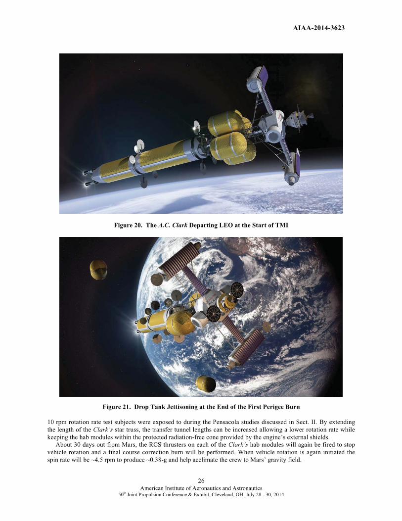
AIAA-2014-3623
26American Institute of Aeronautics and Astronautics
50th Joint Propulsion Conference & Exhibit, Cleveland, OH, July 28 - 30, 2014
Figure 20. The A.C. Clark Departing LEO at the Start of TMI
Figure 21. Drop Tank Jettisoning at the End of the First Perigee Burn
10 rpm rotation rate test subjects were exposed to during the Pensacola studies discussed in Sect. II. By extending
the length of the Clark’s star truss, the transfer tunnel lengths can be increased allowing a lower rotation rate while
keeping the hab modules within the protected radiation-free cone provided by the engine’s external shields.
About 30 days out from Mars, the RCS thrusters on each of the Clark’s hab modules will again be fired to stop
vehicle rotation and a final course correction burn will be performed. When vehicle rotation is again initiated the
spin rate will be ~4.5 rpm to produce ~0.38-g and help acclimate the crew to Mars’ gravity field.

AIAA-2014-3623
27American Institute of Aeronautics and Astronautics
50th Joint Propulsion Conference & Exhibit, Cleveland, OH, July 28 - 30, 2014
Figure 22. Flight Path and Rotation Differences between Discovery and A.C. Clark AG/MTVs
Figure 23. Key Features and Component Lengths of the A.C. Clark AG/MTV
Following propulsive capture into Mars orbit, the Clark uses its cool-down thrust to rendezvous with the orbiting
hab lander. The crew then transfers over to the lander, initiates EDL near the cargo lander and begins the surface
exploration phase of the mission. At the end of the surface stay, the crew lifts off in the MAV with their samples and
returns to the Clark docking at one of the two ports available on the hab modules. After verification and checkout of
all spacecraft systems, the crew jettisons the MAV, the two contingency consumable containers attached to the
opposite sides of the logistics module (shown in Figs. 18 and 23), then performs the TEI burn to begin the trip home.
Flight Vector
��
“Discovery”
BNTR AG/MTV
Vehicle Spin Axis
“A.C. Clark”
NTR AG/MTV
Flig
ht V
ecto
r
25.5 m
27.2 m
“Core” NTPS with extendable nozzles (~2.2 m)
“In-Line” LH2 Tank
4-Sided “Star Truss” / Hab Support Structure
Fwd Comm Antenna (1 of 2)
3 – 25 klbf “Pewee”-class
Engines Forward Adaptor and Cryocooler Radiator
Stretch ISS Hab Module (1 of 2)
Crew
Delivery
MPCV
Port Side
Elevation View
Contingency Consumables
(1 of 2)
Communications Antennas
Megaflex PVAs
RCS
RCS 8.4 m
32.2 m
89.4 m
12 m
LH2 Drop Tanks
Electrical Conduits to Forward PL
Logistics Hub
30 mDocking
Port
1.5 m D
x 11.5 m
Transfer Tunnel

AIAA-2014-3623
28American Institute of Aeronautics and Astronautics
50th Joint Propulsion Conference & Exhibit, Cleveland, OH, July 28 - 30, 2014
During the return trip to Earth, the Clark starts off with a spin rate of 4.5 rpm to provide the Mars gravity
environment that the crew is accustomed to. After the first month, the spin rate is again increased incrementally –from ~5.15 rpm to ~6.79 rpm – to increase the g-loading on the crew by ~0.124-g per month over the next 4 months.
After the final course correction burn, a spin rate of ~7.25 rpm is used during the final month of the mission to help
the crew readapt to Earth’s gravity before re-entry and landing. Following vehicle spin-down, the crew enters the
MPCV and re-enters the atmosphere while the Clark flies past Earth for final disposal into heliocentric space.
A.C. Clark’s Design Features and Characteristics
The A.C. Clark has an overall length of ~89.4 m (Fig. 23) and an IMLEO of ~480 t. Included are (1) the NTPS
(~100 t); (2) the in-line tank element (~95.8 t); (3) the star truss and four LH2 drop tanks (~197.5 t); and (4) the crew
payload section (~86.7 t). The NTPS uses a three-engine cluster of 25 klbf composite fuel Pewee-class engines and
also carries additional external radiation shield mass (~6 t) for crew protection. The NTPS uses an Al/Li LH2 tank
with an outer diameter of 8.4 m and length of 19.7 m. The LH2 tank has a propellant capacity of ~62.4 t. The NTPS
also carries avionics, RCS and propellant, auxiliary battery and PVA power, docking and a reverse turbo-Brayton
ZBO refrigeration system located in the forward cylindrical adaptor section. Twin circular Mega-flex PVAs located
at the forward end of the NTPS provide the electrical power (~6.5 kWe) required for operating the 2-stage
cryocooler system in LEO. The in-line tank has a length of ~22.2 m and a propellant capacity of ~71.6 t. It too has a
ZBO system at its front end plus PVAs that supply the ~7.2 kWe needed to operate it.
The 4-sided star truss on the Clark is ~25.5 m long and attached to it are four drop tanks that carry ~141.4 t of
LH2 propellant. Each tank carries ~35.4 t of propellant and is ~12 m in length. The drop tanks which use only
passive MLI are jettisoned in pairs after the first and second perigee burns (shown in Fig. 21) to reduce vehicle mass
and propellant consumption during the TMI maneuver.
The Clark’s payload element is ~21.5 t heavier than that carried by Discovery. It includes (1) twin habitat
modules and onboard systems (~42.2 t); (2) 5 crew and suits (~1.0 t); (3) the central logistics hub (~7.2 t); (4)
connecting tunnels and hab support brackets (~5.5 t); (5) consumables used during transit (~4.4 t); (6) contingency
consumables in two containers (~8.1 t); (7) the MPCV (~13.5 t); and (8) the RCS and propellant used for spin-up /
spin-down activities (~4.8 t). The Dumbbell A configuration for the Clark (shown below in Fig. 24) has its hab
modules oriented parallel to the vehicle’s spin axis and requires additional structure to support the PVAs deployed
between the central hub and the hab modules. It is expected to have comparable size and slightly heavier mass.
Figure 24. A.C. Clark-A Jettisons Final Drop Tank Set at End of the Second Perigee Burn
With its larger mass, the Clark uses ~254.2 t of LH2 propellant during its primary propulsion maneuvers. With
~75 klbf of total thrust and a Isp of ~906 s, the total engine burn time is ~112.9 minutes (~47.3 minutes and 34
minutes, respectively for the “2-perigee burn” departure, ~18.7 minutes for MOC, and ~12.9 minutes for TEI),

AIAA-2014-3623
29 American Institute of Aeronautics and Astronautics
50th Joint Propulsion Conference & Exhibit, Cleveland, OH, July 28 - 30, 2014
which remains under the ~2 hour accumulated burn time of the NRX-XE. The maximum single burn duration of
~47.3 minutes is also well under the 62 minute record set by the NRX-A6 engine [12]. Finally, U-235 burn-up in
each of the Clark’s engines continues to be minimal: ~52.7 grams (~0.14%) consumed during the four primary
propulsion maneuvers.
IX. Summary and Conclusions
More than 50 years of human spaceflight have provided a wealth of knowledge on the physiological effects of
long-term exposure to 0-g. Significant adverse effects include loss of muscle mass (back and leg muscles) and the
progressive loss of skeletal bone mass (from the lower vertebrae, hip and femur). Another significant effect is fluid
redistribution to the upper body that may be responsible for changes in vision and eye anatomy referred to as VIIP.
In view of these problems and recognizing that exercise and use of pharmaceuticals alone are unlikely to counter the
anticipated effects, an artificial gravity spacecraft offers many advantages and may indeed be an enabling
technology for human flights to Mars.
A number of important human factors must be taken into account in designing an AG spacecraft and in the
selection of the rotation radius, spin rate, and orientation of the habitation module or modules. These factors include
the gravity gradient effect, radial and tangential Coriolis forces, along with cross-coupled acceleration effects. A
number of AG spacecraft concepts have been proposed in the past using aerobraking and chemical propulsion,
tethers, electric propulsion, and NTP. Of these options, the NTR is the most attractive. It is a proven technology with
a high thrust and high Isp (~100% higher than LOX/LH2 chemical rockets) capability that is particularly attractive
for AG missions allowing it to more readily accommodate the heavier payload mass and increased RCS propellant
loading required for multiple spin-up / spin-down cycles.
Conceptual designs for AG/MTVs using both BNTP and NTP have been presented. The Copernicus-B and
Discovery designs use TRITON bimodal engines and Brayton power conversion to generate 10’s of kilowatts of
spacecraft electrical power during the mission coast phase eliminating the need for large PVAs. Both spacecraft
designs use a single inflatable TransHab crew module with multiple vertical floors oriented radial to the vehicle’s
spin axis. The configuration of the Copernicus-B and Discovery spacecraft designs – long and linear – is also
naturally compatible with AG operation. When using the SLS-1A launch vehicle, with lower lift capability and
smaller diameter fairing, an extra in-line tank must be added to the Discovery. This adds length to the Discovery thus
lowering its required spin rates for a given acceleration level. By rotating the vehicles about their center-of-mass and
perpendicular to its flight vector at spin rates of ~2.7 – 5.2 rpm, a centrifugal force and AG environment
corresponding to ~0.38 – 1.0-g can be established to help maintain crew fitness out to Mars and back, also while in
Mars orbit in the event of a surface abort. While operationally attractive from a vehicle standpoint, the bimodal
engines used on Copernicus-B and Discovery are more complex and viewed as a second-generation system. They
also require a significantly larger inventory of HEU in their reactor cores.
As shown in this paper, bimodal engines are not the only option for AG spacecraft. In fact it is more likely that
initial designs will use conventional NTP along with PVAs to supply auxiliary power. The A.C. Clark is such a
design. It carries twin cylindrical ISS-type habitat modules with their long axes oriented perpendicular to the
longitudinal spin axis of the vehicle. The twin habs are connected to a central operations hub located at the front of
the spacecraft via two pressurized tunnels that provide an ~17 m rotation radius. With spin rates of ~4.5 – 7.25 rpm,
a centrifugal force of ~0.38 – 1.0-g can be established at the center of the habitat modules. Approximately 210 m2 of
PVA area is also mounted to the Sun-facing side of the Clark’s hab modules and tunnels that can supply ~26 kWe of
crew and spacecraft electrical power while in Mars orbit. It is also possible to orient the hab modules parallel to the
Clark’s longitudinal spin axis that is expected to have accompanying human factors benefits.
Finally, it is important to remember that long duration deep space missions will also expose the crew to galactic
cosmic radiation and multiple solar flare events. Using NTP, shorter transit times to and from Mars are also possible
reducing the crew’s total exposure during the mission. Today, NTP technology is receiving increased attention.
NASA’s Advanced Exploration Systems (AES) program restarted an NTP technology development and
demonstration effort with its Nuclear Cryogenic Propulsion Stage (NCPS) project in FY’12 [34]. This initial 3-year
Phase I effort (FY’12 – 14) will be followed by a Phase II effort in FY’ 15 –17 involving fuel element irradiation
testing and non-nuclear, subscale validation testing of the SAFE (Subsurface Active Filtration of Exhaust)
“borehole” ground test option at the Nevada Test Site. If successful, this effort could be followed by major system-
level technology demonstrations that include ground testing a small (~7.5 klbf), scalable NTR by 2023, followed by
a flight test of a small NTP stage in 2025.

AIAA-2014-3623
30 American Institute of Aeronautics and Astronautics
50th Joint Propulsion Conference & Exhibit, Cleveland, OH, July 28 - 30, 2014
Acknowledgments The authors express their thanks to John Warren and Chris Moore (NASA/HQ), Mike Houts (MSFC), and John
Taylor, Mark Klem and George Schmidt (GRC) for their funding support and encouragement of this work through
the Advanced Exploration Systems (AES) program’s Nuclear Cryogenic Propulsion Stage (NCPS) project. The
authors also wish to thank Clint Ensworth for his assessment of the TVC and RCS control requirements needed for
AG vehicles. The author (SKB) also expresses his thanks to Bob Sauls ([email protected]) for his exceptional
digital images depicting the different AG vehicle concepts developed by GRC and presented in this paper.
References
[1] National Research Council Report, “Pathways to Exploration – Rationales and Approaches for a U. S. Program
of Human Space Exploration”, The National Academy Press, Washington, D.C., www.nap.edu, (June 4, 2014).
[2] Borowski, S. K., Dudzinski, L. A., and McGuire, M. L., “Artificial Gravity Vehicle Design Option for NASA’s
Human Mars Mission Using “Bimodal” NTR Propulsion,” AIAA-99-2545, American Institute of Aeronautics and
Astronautics (1999).
[3] Nicogossian, A. E., and McCormack, P. D., “Artificial Gravity – A Countermeasure for Zero Gravity”, 38th
Congress of the IAF, Brighton, England, IAF/IAA-87-533 (1987).
[4] Tarver, W., “What's New in Space Medicine – Can you say VIIP?”, NASA/LSAH Newsletter, Vol. 18, Issue 1,
Spring 2012.
[5] Clark, B. C., “Human Exploration of Mars”, AIAA-88-0064, American Institute of Aeronautics and Astronautics
(1988).
[6] Exploration Studies Technical Report, FY 1988 Status, NASA Technical Memorandum 4075, Vol. II: Study
Approach and Results (1988).
[7] Office of Exploration FY 1989 Annual Report, NASA Technical Memorandum 4170, Vol. II: Space
Transportation Systems (1989).
[8] Clark, B. C., “Concept 6: An Artificial Gravity Mars Spacecraft”, Space Technology, Vol. 11, No. 4, pgs. 205 -
215 (1991).
[9] Borowski, S. K., Dudzinski, L. A., and McGuire, M. L., “Bimodal Nuclear Thermal Rocket (NTR) Propulsion
for Power-Rich, Artificial Gravity Human Exploration Missions to Mars,” IAA-01-IAA.13.3.05, 52nd
International
Astronautical Congress, Toulouse, France (2001).
[10] NASA/NSBRI Artificial Gravity Workshop: Proceedings and Recommendations, W. L. Paloski and L. R.
Young, eds., League City, Texas, (Jan. 14-15, 1999).
[11] Artificial Gravity Research to Enable Human Space Exploration, L. R. Young, K. Yajima, and W. L. Paloski
eds., International Academy of Astronuatics, 2009.
[12] Koeing, D. R., “Experience Gained from the Space Nuclear Rocket Programs (Rover / NERVA),” Los
Alamos National Laboratory, Report LA-10062-H, Los Alamos, NM, May 1986.
[13] Human Exploration of Mars Design Reference Architecture 5.0, Drake, Bret G., ed., National
Aeronautics and Space Administration, NASA-SP-2009-566, Washington, DC, July 2009.
[14] Borowski, S. K., McCurdy, D. R., and Packard, T. W., “7–Launch NTR Space Transportation System for
NASA’s Mars Design Reference Architecture (DRA) 5.0”, AIAA-2009-5308, August 2009.
[15] 2014 Artificial Gravity Workshop White Paper, Norsk, P., Arya, M., Smith, L., Cromwell, R., Kugler, J.,
Gilbert, J., and Baumann, D., eds., Ames Research Center, (Feb. 19-20, 2014).
[16] Joosten, B. K., “Preliminary Assessment of Artificial Gravity Impacts to Deep-Space Vehicle Design”, JSC-
63743, 2007.
[17] Loret, B. J., “Optimization of Space Vehicle Design with Respect to Artificial Gravity”, Aerospace Medicine,
Vol. 34, (1963), pgs. 430 – 441.
[18] Stone, R. W., “An Overview of Artificial Gravity”, Fifth Symposium on the Role of Vestibular Organs in Space
Exploration”, Pensacola, Florida (Aug. 1970), NASA SP–314, (1973), pgs. 23 – 33.
[19] Thompson, A. B., “Physiological Design Criteria for Artificial Gravity Environments in Manned Space
Systems”, NASA SP–77, (1965), pgs. 233 – 241.
[20] Shipov, A. A., “Artificial Gravity”, in Space Biology and Medicine: Humans in Spaceflight, Nicogossian, A.
E., Moehler, S. R., Gazenko, O. G., Gregoriev, A. I., eds., Vol. 3, Book 2, American Institute of Aeronautics and
Astronautics, (1997), pgs. 233 – 241.

AIAA-2014-3623
31 American Institute of Aeronautics and Astronautics
50th Joint Propulsion Conference & Exhibit, Cleveland, OH, July 28 - 30, 2014
[21] Graybiel, A., Kennedy, R. S., Guedry, F. E., McLeod, M. E., Colehour, J. K., Miller, E. F., Knoblock, E. C.,
Mertz, W., “The Effects of Exposure to a Rotating Environment (10 rpm) on Four Aviators for a Period of Twelve
Days”, NASA SP–77, (1965), pgs. 295 - 337; also Aerospace Medicine, Vol. 36, (1965), pgs. 733 – 754.
[22] Bergstedt, M., “Stepwise Adaptation to a Velocity of 10 rpm in the Pensacola Slow Rotating Room”, NASA
SP–77, (1965), pgs. 339 - 345.
[23] Schnitzler, B. G., Borowski, S. K., and Fittje, J. E., “25,000-lbf Thrust Engine Options Based on the Small
Nuclear Rocket Engine Design”, AIAA-2009-5239, August 2009.
[24] Durham, F. P., “Nuclear Engine Definition Study Preliminary Report, Volume 1 - Engine Description”, Los
Alamos National Laboratory, Report LA-5044-MS Vol. 1, Los Alamos, NM, September 1972.
[25] Schnitzler, B. G., Borowski, S. K., and Fittje, J. E., “Lower Thrust Engine Options Based on the Small Nuclear
Rocket Engine Design”, AIAA-2011-5846, August 2011.
[26] Schnitzler, B. G., “Small Reactor Designs Suitable for Direct Nuclear Thermal Propulsion: Annual Report”,
Idaho National Laboratory, Report INL/EXT-13-28027, Idaho Falls, ID, January 2013.
[27] Taub, J. M., “A Review of Fuel Element Development for Nuclear Rocket Engines”, Los Alamos National
Laboratory, Report LA-5931, Los Alamos, NM, June 1975.
[28] Borowski, S. K., McCurdy, D. R., and Packard, T. W., “Nuclear Thermal Propulsion (NTP): A Proven Growth
Technology for Human NEO/Mars Exploration Missions”, 2012 IEEE Aerospace Conference, IEEEAC paper
#1403, Big Sky, MT, March 2012.
[29] Joyner, C. R., et al., “TRITON: A TRImodal capable, Thrust Optimized, Nuclear Propulsion and Power System
for Advanced Space Missions”, AIAA-2004-3863, American Institute of Aeronautics and Astronautics (2004).
[30] Marchaterre, J. F., et al., “Nuclear Rocket Program Terminal Report”, ANL-7236, Argonne National
Laboratory, Argonne, IL, February 1968.
[31] Kruger, G. B., “710 High-Temperature Gas Reactor Program Summary Report”, General Electric, Report
GEMP-600, Vol. 1, Cincinnati, OH, 1968.
[32] Schnitzler, B. G., “Small Reactor Designs Suitable for Direct Nuclear Thermal Propulsion: Annual Report”,
Idaho National Laboratory, Report INL/EXT-13-28027, Idaho Falls, ID, January 2013.
[33] Stewart, M. E.M., and Schnitzler, B. G., “Thermal, Fluid, and Structural Analysis of a Cermet Fuel Element”,
AIAA-2012-3559, July 30 – August 1, 2012
[34] Borowski, S. K., McCurdy, D. R., and Packard, T. W., “Modular Growth NTR Space Transportation System
for Future NASA Human Lunar, NEA and Mars Exploration Missions”, AIAA-2012-5144, September 2012.
[35] Borowski, S. K., McCurdy, D. R., and Packard, T. W., “Nuclear Thermal Propulsion (NTP): A Proven, Growth
Technology for ‘Fast Transit’ Human Missions to Mars”, AIAA-2013-5354, September 2013.
[36] Ensworth, C. B., “Thrust Vector Control for Nuclear Thermal Rockets”, AIAA-2013-4075, September 2013.