Embed Size (px)
Citation preview
1
Technical Article
Convenient Charging of Electric Vehicles
Today, charging of EVs generally takes place at home. Just a few
charging stations are available in public areas – as part of model
studies. Since vehicles are parked frequently, e.g. while shopping
or at work, they can be charged during these times. In the future, a
broadly based and standardized infrastructure will be built up for
this purpose. It has to offer a standardized mechanism for charging
the batteries, and it must also support a method for easy payment.
To enable convenient payment, debiting of the small amounts
should be conveniently handled by automated electronic billing.
International standardization and its distribution
Widespread establishment of a charging infrastructure can only be
properly achieved if all aspects of the charging process are stan
dardized across manufacturers. The connector and cable as well as
the charging communication must be standardized for all EVs and
charging stations. In Europe, charging communication is described
in the framework of ISO 15118. In the USA, this is being done in
SAE (Figure 1). In Japan, there is already the CHAdeMO standard
and a charging station network of over 250 stations.
According to the “National Development Plan for Electro
mobility” by the German federal government, Germany should
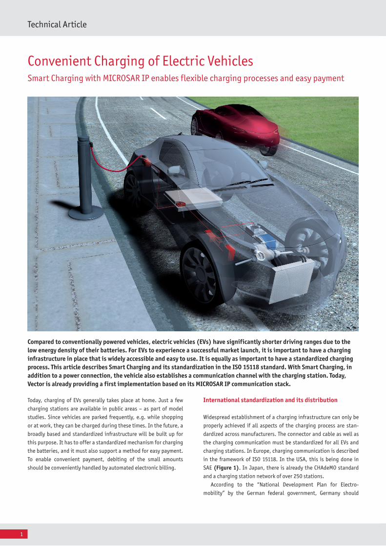
Compared to conventionally powered vehicles, electric vehicles (EVs) have significantly shorter driving ranges due to the low energy density of their batteries. For EVs to experience a successful market launch, it is important to have a charging infrastructure in place that is widely accessible and easy to use. It is equally as important to have a standardized charging process. This article describes Smart Charging and its standardization in the ISO 15118 standard. With Smart Charging, in addition to a power connection, the vehicle also establishes a communication channel with the charging station. Today, Vector is already providing a first implementation based on its MICROSAR IP communication stack.
Smart Charging with MICROSAR IP enables flexible charging processes and easy payment
2July 2011
become the lead market for electromobility. This plan calls for one
million EVs to be on the roads of Germany by 2020.
Providing the energy
Charging of EVs can cause a severe load of local electrical distribu
tion networks. Today’s electrical grids require some time to react to
such load changes. If several charging EVs draw high power simul
taneously in one location, e.g. in a parking garage, this could lead
to a local grid overload and outage.
Until now, no consideration has been given to the total power
requirement for charging EVs on the electrical grid. As soon as the
driver plugs in the vehicle’s charging cable, charging begins at the
maximum possible current, and this adds a certain amount of load
to the grid. This might appear to be similar to the model of fueling
up at a normal fuel station, where energy is always in stock and is
easy to obtain in the form of gasoline. But the situation with elec
trical energy differs fundamentally. It cannot be stored as simple
as gasoline and be drawn from storage. Nonetheless, by introduc
ing an intelligent electrical grid (Smart Grid) and by using intelli
gent charging, it is possible to avoid overload and grid failure. In a
Smart Grid, data is exchanged about power requirements, and the
electrical grid can be optimized accordingly.
The power needed for a charging operation lies between 3kW
and 20kW, or even over 100kW, depending on the available power
connection and charging profile. By comparison, a typical citizen
in Germany uses an average of 35kWh of daily electrical energy,
depending on household size. To operate the grid so that it is more
stable, the energy provider needs time to supply the charging
energy. One way to obtain this time is to delay the start of the
charging operation by several tens of seconds.
Charging method for DC or AC power
In charging the batteries, two different procedures can be distin
guished. First, the battery can be charged with alternating current,
which is available in the electrical grid as singlephase or three
phase AC. Nearly any electrical outlet may be used for charging
here. However, the charger must be installed in the vehicle, which
means additional weight. In the second variant, the battery is
charged with DC electricity. In this case, the charger is located out
side of the vehicle, in the charging station, and it generates the DC
voltage for charging the batteries. In this case, the weight of the
charger does not matter, but costs are higher for such a DC charg
ing station. Since these two charging processes each have their
advantages and disadvantages, they are used in parallel.
Communication between vehicle, charging station and energy provider
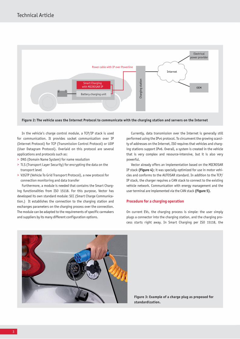
If the vehicle only has to communicate with the charging station
for charging, the choice of transmission medium and protocol
would be quite flexible. However, the charging station and vehicle
also need to communicate with various servers on the Internet
(Figure 2). Therefore, it makes sense to use the conventional pro
tocols of IPbased networks. Since requirements call for just using
the cable for the charging current – and no auxiliary lines for com
munication – communication is implemented directly via the charg
ing cable (Figure 3). PLC technology (Power Line Communication)
is available for this purpose. In this system, the data stream is
modulated onto the power line. This system is more familiar under
the names Homeplug AV and IPoverpowerline in the consumer
products field; they offer a simple way to set up private computer
networks via a building’s power lines.
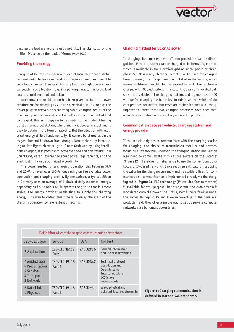
Figure 1: Charging communication is defined in ISO and SAE standards.
SAE J2836
Europe USA
ISO/IEC 15118Part 1
Definition of vehicle to grid communication interface
ISO/IEC 15118Part 2
ISO/IEC 15118Part 3
SAE J2847
SAE J2931
ISO/OSI Layer
7 Application
7 Application6 Presentation5 Session4 Transport3 Network
2 Data Link1 Physical
General information and use case definition
Technical protocoldescription and Open Systems Interconnections (OSI) layer requirements
Wired physical and data link layer requirements
Content
3
Technical Article
Currently, data transmission over the Internet is generally still
performed using the IPv4 protocol. To circumvent the growing scarci
ty of addresses on the Internet, ISO requires that vehicles and charg
ing stations support IPv6. Overall, a system is created in the vehicle
that is very complex and resourceintensive, but it is also very
powerful.
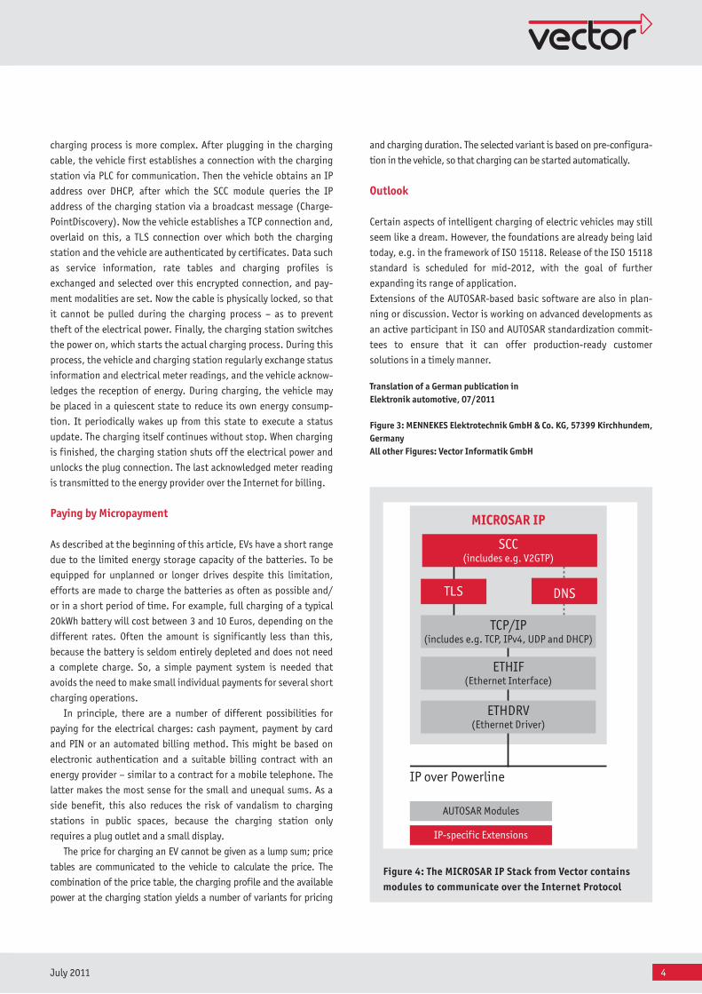
Vector already offers an implementation based on the MICROSAR
IP stack (Figure 4); it was specially optimized for use in motor vehi
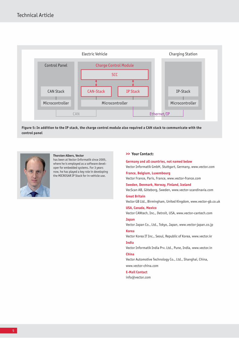
cles and conforms to the AUTOSAR standard. In addition to the TCP/
IP stack, the charger requires a CAN stack to connect to the existing
vehicle network. Communication with energy management and the
user terminal are implemented via the CAN stack (Figure 5).
Procedure for a charging operation
On current EVs, the charging process is simple: the user simply
plugs a connector into the charging station, and the charging pro
cess starts right away. In Smart Charging per ISO 15118, the
In the vehicle’s charge control module, a TCP/IP stack is used
for communication. It provides socket communication over IP
(Internet Protocol) for TCP (Transmission Control Protocol) or UDP
(User Datagram Protocol). Overlaid on this protocol are several
applications and protocols such as:
DNS (Domain Name System) for name resolution >
TLS (Transport Layer Security) for encrypting the data on the >
transport level
V2GTP (Vehicle To Grid Transport Protocol), a new protocol for >
connection monitoring and data transfer
Furthermore, a module is needed that contains the Smart Charg
ing functionalities from ISO 15118. For this purpose, Vector has
developed its own standard module: SCC (Smart Charge Communica
tion.) It establishes the connection to the charging station and
exchanges parameters on the charging process over the connection.
The module can be adapted to the requirements of specific carmakers
and suppliers by its many different configuration options.
Fig ure 2: The vehicle uses the Internet Protocol to communicate with the charging station and servers on the Internet
Fig ure 3: Example of a charge plug as proposed for standardization.
Char
ging
sta
tion
Power cable with IP over Powerline
Ladesteuergerät
+ -
Smart Chargingwith MICROSAR IP
Battery charging unit
InternetInternet
OEM
Electricalpower provider
4July 2011
IP over Powerline
ETHDRV(Ethernet Driver)
TLS
ETHIF(Ethernet Interface)
AUTOSAR Modules
IP-specific Extensions
TCP/IP(includes e.g. TCP, IPv4, UDP and DHCP)
SCC(includes e.g. V2GTP)
DNS
MICROSAR IP
charging process is more complex. After plugging in the charging
cable, the vehicle first establishes a connection with the charging
station via PLC for communication. Then the vehicle obtains an IP
address over DHCP, after which the SCC module queries the IP
address of the charging station via a broadcast message (Charge
PointDiscovery). Now the vehicle establishes a TCP connection and,
overlaid on this, a TLS connection over which both the charging
station and the vehicle are authenticated by certificates. Data such
as service information, rate tables and charging profiles is
exchanged and selected over this encrypted connection, and pay
ment modalities are set. Now the cable is physically locked, so that
it cannot be pulled during the charging process – as to prevent
theft of the electrical power. Finally, the charging station switches
the power on, which starts the actual charging process. During this
process, the vehicle and charging station regularly exchange status
information and electrical meter readings, and the vehicle acknow
ledges the reception of energy. During charging, the vehicle may
be placed in a quiescent state to reduce its own energy consump
tion. It periodically wakes up from this state to execute a status
update. The charging itself continues without stop. When charging
is finished, the charging station shuts off the electrical power and
unlocks the plug connection. The last acknowledged meter reading
is transmitted to the energy provider over the Internet for billing.
Paying by Micropayment
As described at the beginning of this article, EVs have a short range
due to the limited energy storage capacity of the batteries. To be
equipped for unplanned or longer drives despite this limitation,
efforts are made to charge the batteries as often as possible and/
or in a short period of time. For example, full charging of a typical
20kWh battery will cost between 3 and 10 Euros, depending on the
different rates. Often the amount is significantly less than this,
because the battery is seldom entirely depleted and does not need
a complete charge. So, a simple payment system is needed that
avoids the need to make small individual payments for several short
charging operations.
In principle, there are a number of different possibilities for
paying for the electrical charges: cash payment, payment by card
and PIN or an automated billing method. This might be based on
electronic authentication and a suitable billing contract with an
energy provider – similar to a contract for a mobile telephone. The
latter makes the most sense for the small and unequal sums. As a
side benefit, this also reduces the risk of vandalism to charging
stations in public spaces, because the charging station only
requires a plug outlet and a small display.
The price for charging an EV cannot be given as a lump sum; price
tables are communicated to the vehicle to calculate the price. The
combination of the price table, the charging profile and the available
power at the charging station yields a number of variants for pricing
Fig ure 4: The MICROSAR IP Stack from Vector contains modules to communicate over the Internet Protocol
and charging duration. The selected variant is based on preconfigura
tion in the vehicle, so that charging can be started automatically.
Outlook
Certain aspects of intelligent charging of electric vehicles may still
seem like a dream. However, the foundations are already being laid
today, e.g. in the framework of ISO 15118. Release of the ISO 15118
standard is scheduled for mid2012, with the goal of further
expanding its range of application.
Extensions of the AUTOSARbased basic software are also in plan
ning or discussion. Vector is working on advanced developments as
an active participant in ISO and AUTOSAR standardization commit
tees to ensure that it can offer productionready customer
solutions in a timely manner.
Translation of a German publication in Elektronik automotive, 07/2011
Figure 3: MENNEKES Elektrotechnik GmbH & Co. KG, 57399 Kirchhundem, GermanyAll other Figures: Vector Informatik GmbH
5
Technical Article
Thorsten Albers, Vector has been at VectorInformatik since 2005, where he is employed as a software developer for embedded systems. For 3 years now, he has played a key role in developing the MICROSAR IP Stack for invehicle use.
>> Your Contact:
Germany and all countries, not named belowVector Informatik GmbH, Stuttgart, Germany, www.vector.com
France, Belgium, Luxembourg Vector France, Paris, France, www.vectorfrance.com
Sweden, Denmark, Norway, Finland, IcelandVecScan AB, Göteborg, Sweden, www.vectorscandinavia.com
Great BritainVector GB Ltd., Birmingham, United Kingdom, www.vectorgb.co.uk
USA, Canada, MexicoVector CANtech, Inc., Detroit, USA, www.vectorcantech.com
JapanVector Japan Co., Ltd., Tokyo, Japan, www.vectorjapan.co.jp
KoreaVector Korea IT Inc., Seoul, Republic of Korea, www.vector.kr
IndiaVector Informatik India Prv. Ltd., Pune, India, www.vector.in
ChinaVector Automotive Technology Co., Ltd., Shanghai, China,
www.vectorchina.com
E-Mail [email protected]
CAN
Control Panel
CAN Stack
Microcontroller
Charge Control Module
CAN-Stack IP Stack
Charging Station
IP-Stack
Microcontroller
Electric Vehicle
Ethernet/IP
SCC
Microcontroller
Fig ure 5: In addition to the IP stack, the charge control module also required a CAN stack to communicate with the control panel