Embed Size (px)
Citation preview

CEWCONTROLS INC.
Excellence Without Compromise
R TECHNICAL BULLETINTB 117 Models EWC STMS 2A & 3A
Leave this bulletin on the job site
EWC Controls Inc. 385 Highway 33 Englishtown, NJ 07726 800-526-4048 732-446-3110 FAX 732-446-5362
. . . . .
Warning: Control panel does not have any built in time delays.The HVAC system must have its own or, installer provided time delay relays to prevent system short cycling.
TABLE OF CONTENTS PAGE
1 Introduction and Specifications
2 Two stage systems
3 Heat pump systems
4 Two stage wiring diagrams
& Heat pump wiring diagrams
7 Expansion panel wiring
& Transformer and damper wiring
& Service notes
12 Diagram overview
SPECIFICATIONS
Power Requirements: 24volt 60 Hz 40VA
Wiring Connections: Screw terminal blocks for thermostat gauge wire.
Mounting: Mounts with 4 screws and mollies (included).
Panel Dimensions: Length: 11 5/8" (295mm); Width: 9" (229mm);Depth: 1 1/4" (32mm).
EWC-STMS-2A EWC-STMS-3A
R
CONTROLS INC.Englishtown, NJ CONTROL SYSTEM
D7 D11
D12
D10
D9
D3
D4
D6
D22
D21
D19
D20
D32
D31
D33
D34
D30
D29
D27
D28
D26
D25
D23
D24
D5
D8
D2
D1
Z5 Z6
Z7
Z2
Z1
Z4
Z10
Z11
Z8
Z9
K5 K6
K7
K2
K1
K4
K8
K11
K10
K9
C5 C6
C7
C2
C1
C4
C10
C11
C8
C9
M1M2M4M6
ZONE 2MOTOR
Y1W1R
Y2W2C
ZONE 2 T'STAT
RC + -
OY2W2
EW2W1Y2Y1GCR
GHC
HPOB
SYSTEM
HPY2W2ROEG
Y1W1C
ZONE 1 T-STAT
R2
R1
J1
OPENSW2
CLOSED
M1M2M4M6
ZONE 1MOTOR
1
2
24VT'FORMER
CB1
OPENSW1
CLOSED
EWC-STMS-2A Control Panel
{ADDITIONALZONE PANEL
CAUTIONPLEASE read allinstructions carefullybefore starting theinstallation procedures.DO NOT connect tovoltages above 30 VAC.
R
CONTROLS INC.Englishtown, NJ CONTROL SYSTEM
D11
D12
D10
D9
D3
D4
D6
D22
D21
D19
D20
D32
D31
D33
D34
D30
D29
D27
D28
D26
D25
D23
D24
D5
D8
D2
D1
Z6
Z7
Z1
Z4
Z10
Z11
Z8
Z9
K5
K6
K7
K1
K4
K8
K11
K10
K9
D7
Z5
Z2
C5
D16
D18
D15
D17D14
D13
Z3
C3
C6
C7
C2
C1
C4
C10
C11
C8
C9
Y1W1R
Y2W2C
ZONE 2 T'STAT
Y1W1R
Y2W2C
ZONE 3 T'STAT
RC + -
OY2W2
M1M2M4M6
ZONE 1MOTOR
EW2W1Y2Y1GCR
GHC
HPOB
SYSTEM
1
2
24VT'FORMER
HPY2W2ROEG
Y1W1C
ZONE 1 T-STAT
R2
R3
R1
CB1
J1
K2
M1M2M4M6
ZONE 2MOTOR
OPENSW2
CLOSED
K3
M1M2M4M6
ZONE 3MOTOR
OPENSW3
CLOSED
OPENSW1
CLOSED
EWC-STMS-3A Control Panel
{ADDITIONALZONE PANEL
CAUTIONPLEASE read allinstructions carefullybefore starting theinstallation procedures.DO NOT connect tovoltages above 30 VAC.
The STMS control panel will interface with single stage or two stage gas or oil fired furnaces and boilers, with electric air conditioning systems, or
two stage heat, single stage cool heat pumps.
Warning: These panels are designed for use with 24 volts AC power. Do not use any other voltage! Use caution to avoid electric shock or equipment damage. All wiring should be done in accordance with local and national codes.
This technical bulletin contains information and wiring diagrams for the ULTRA ZONE, STMS-2A and 3A control panels. Please read and familiarize yourself with the proper wiring diagrams before you start the installation. We have compiled these diagrams based on the most frequently asked questions regarding the wiring of these panels. The STMS panel will interface with many HVAC systems. If your particular application does not match any of the supplied diagrams, call the technical support hot line. If the system does not operate properly or you experience trouble during the installation, check this bulletin against the field wiring for shorts or mis-wiring. If the problem cannot be resolved, then call the technical support hot line.
5
8
10
6
9
11
The heating and cooling system changeover,emergency heat, and fan operations arecontrolled by the subbase on the zone 1thermostat. When using thermostats with manual changeover switches (HEAT-OFF-COOL) on zones other than zone 1,make sure all zones are in the same mode at all times. If zone 1 system mode is changed, then the other zones should be changed as well, for proper operation. Auto changeover thermostats on other zones will eliminate the need for manual changeover. Most battery powered or AC powered thermostats can be used and wired directly to the panel. Foreven greater comfort and energy savings,setback thermostats can be wired to any or allzones.
P/N 090375A0117 REV E 16 APR 2001 Copyright EWC Controls C 1999-2003 All Rights Reserved

TWO STAGE SYSTEMS
CONVENTIONAL TWO STAGE SYSTEMThe mode of operation is determined by the position of the system selector switch on the subbase of the zone 1 thermostat. Switching subbases are not required on the other zones.
The panel will be in the heat mode when thezone 1 thermostat subbase is in either the "HEAT" position or the "OFF" position. This allowsany zone to call for heat, except zone 1 when itssubbase is in the off position. When a zone calls for heat, the panel closes the circuit from the system "R" terminal to the system "W1" terminal, energizing the first stage heat relay. Also in the heat mode, system terminal "R" is in constant make to system "B" terminal. If any zone is equipped with a 2 stage thermostat, when the thermostat makes on the second stage, the panel will also make the system terminal "R" to system "W2" to energize the second stage heat relay.
Wiring a 2 stage HVAC system to the EWC STMS controlpanel is similar to wiring directly to a thermostat subbase. The following terminals are on the system terminal block.R - To hot side of system transformer.B - Unused.O - Unused.Y1/Y2 - To compressor relays first and second stage.W1/W2 - To heat relays first and second stage.E - Unused.GC - To fan relay if cycled in cool mode only.GHC- To fan relay if cycled in cool and heat mode.HP- Unused.
COOL MODE
HEAT MODE
The panel is in the cool mode when the zone 1thermostat subbase is switched to the cool position. In this mode any zone can call for cooling.When a zone calls for cooling, the panel closes the circuit from the system "R" terminal to the system "Y1"and "G" terminals, energizing the first stage cool relay, and the fan relay. Also in the cool mode, the system "R" terminal is in constant make to the system "O" terminal. If any zone is equipped with a 2 stage thermostat, when the thermostat makes on the secondstage, the panel will also make system "R" terminal to the system "Y2" terminal, to energize the second stage compressor relay.
There is no true off mode. When the zone 1 thermostat is in the off position, the remaining zones can still call for heat. Each zone thermostat must have its own switching subbase, with "OFF" position, in order to turn off each individual zone.
Manual control or continuous operation of the fanis controlled by the position of the fan switch on the zone 1 thermostat subbase only. The remainingzones are not capable of individual fan control. TheSTMS system terminal block provides two fan control connections, "GC" and "GHC". The "GC" terminal will energize the fan relay in the cool mode only. The"GHC" terminal will energize the fan relay in bothheating and cooling modes. Used for electric heatand some hydronic heat applications.
Thermostat wiring depends on the type of thermostats used.The following is a description and the requirements of theterminals on the zone 1 thermostat terminal block.R- Hot side of 24 volts to thermostat.C- Common side of 24 volts to thermostat. If needed.Y1- Must be made to "R" on a call for 1st stage cooling.Y2- Must be made to "R" on a call for 2nd stage cooling.HP- Unused in two stage operation.O- Must be made to "R" continuously when system switch is in the cool position.E- Unused in two stage operation.W1- Must be made to "R" on a call for 1st stage heating.W2- Must be made to "R" on a call for 2nd stage heating.G- Must be made continuously when fan switch is in the "ON" position.
ZONE 1
Zone 2/3 thermostat is a simple single stage heat-coolthermostat or a 2 stage heat and 2 stage cool dependingon requirements of a particular zone. The following is a description and the requirements of the terminals on thezone 2/3 thermostatR- High side of 24 Volts to thermostat.C- Low side of 24 Volts to thermostat. If neededY1- Must be made to "R" on a call for cooling.Y2- Must be made to Y1 on a call for second stage cooling.W1- Must be made to "R" on a call for heat.W2- Must be made to "W1" on a call for second stage heat.
ZONE 2/3
THERMOSTATS
2 EWC Controls Inc. 385 Highway 33 Englishtown, NJ 07726 800-446-3110 FAX 732-635-8646 E-Mail- [email protected]
FAN
OFF MODE
SYSTEM
OPERATION WIRING
Use 3 conductor wire from each zone damper motor terminal to the corresponding terminals on the STMS or STEXcontrol panels. Consult wiring diagrams for damper types.NOTE: When operating more than one damper motor perzone, consult specific wiring diagrams.When any zone is calling, that damper will be in the openposition. Any zone not calling will be in the closed position.When all zones are satisfied, the position of the damper iscontrolled by the "OPEN/CLOSED" switches on the panel.OPEN POSITION - The damper will drive open when all zones are satisfied.CLOSED POSITION - The damper will drive closed when all zones are satisfied except with SMD,BMD, IMD dampers, the last zone to satisfy will always remainopen regardless of switch position.
ZONE DAMPER MOTORS
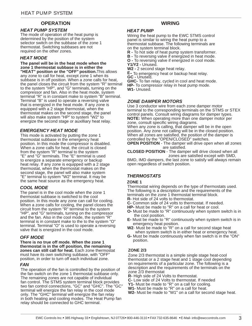
HEAT PUMP SYSTEM
HEAT PUMP SYSTEM The mode of operation of the heat pump isdetermined by the position of the system selector switch on the subbase of the zone 1 thermostat. Switching subbases are not required on the other zones.
The panel will be in the heat mode when thezone 1 thermostat subbase is in either the "HEAT" position or the "OFF" position.This allowsany zone to call for heat, except zone 1 when itssubbase is in off position. When a zone calls for heat, the panel closes the circuit from the system "R" terminal to the system "HP", and "G" terminals, turning on the compressor and fan. Also in the heat mode, system terminal "R" is in constant make to system "B" terminal.Terminal "B" is used to operate a reversing valve that is energized in the heat mode. If any zone is equipped with a 2 stage thermostat, when the thermostat makes on the second stage, the panel will also make system "HP" to system "W2" to energize the second stage or auxilliary heat relay.
Wiring the heat pump to the EWC STMS controlpanel is similar to wiring the heat pump to a thermostat subbase. The following terminals are on the system terminal block.R - To hot side of heat pump system transformer.B - To reversing valve if energized in heat mode.O - To reversing valve if energized in cool mode.Y1/Y2 - Unused.W2 - 2 second stage heat relay.EGC - Unused.GHC- To fan relay, cycled in cool and heat mode.HP- To compressor relay in heat pump mode.W1- Unused.
To emergency heat or backup heat relay.
This mode is activated by putting the zone 1thermostat subbase in the emergency heatposition. In this mode the compressor is disabled.When a zone calls for heat, the circuit is closedfrom the system "R" terminal to the system "E" and "G" terminals. The "E" terminal is usedto energize a separate emergency or backup heat relay. If any zone is equipped with a 2 stage thermostat, when the thermostat makes on the second stage, the panel will also make system"E" terminal to system "W2" terminal. It may be the same heat source as the emergency heat.
The panel is in the cool mode when the zone 1thermostat subbase is switched to the cool position. In this mode any zone can call for cooling.When a zone calls for cooling, the panel closes the circuit from the system "R" terminal to the system"HP", and "G" terminals, turning on the compressor and the fan. Also in the cool mode, the system "R"terminal is in constant make to the to the system "O"terminal. Terminal "O" is used to operate a reversingvalve that is energized in the cool mode.
There is no true off mode. When the zone 1 thermostat is in the off position, the remaining zones can still call for heat. Each zone thermostatmust have its own switching subbase, with "OFF" position, in order to turn off each individual zone.
The operation of the fan is controlled by the position of the fan switch on the zone 1 thermostat subbase only.The remaining zones are not capable of individualfan control. The STMS system terminal block provides two fan control connections, "GC" and "GHC". The "GC" terminal will energize the fan relay in the cool modeonly. The "GHC" terminal will energize the fan relayin both heating and cooling modes. The Heat Pump fanrelay should be connected to GHC terminal.
Thermostat wiring depends on the type of thermostats used.The following is a description and the requirements of theterminals on the zone 1 thermostat terminal block.R- Hot side of 24 volts to thermostat.C- Common side of 24 volts to thermostat. If needed.HP- Must be made to "R" on a call for heat or cool.O- Must be made to "R" continuously when system switch is in the cool position.E- Must be made to "R" continuously when system switch is in emergency heat position.W2- Must be made to "R" on a call for second stage heat when system switch is in either heat or emergency heat.G- Must be made continuously when fan switch is in the "ON" position.
ZONE 1
THERMOSTATS
-
3EWC Controls Inc. 385 Highway 33 Englishtown, NJ 07726 800-446-3110 FAX 732-635-8646 E-Mail- [email protected]
FAN
OFF MODE
COOL MODE
EMERGENCY HEAT MODE
HEAT MODE
HEAT PUMP
OPERATION WIRING
Zone 2/3 thermostat is a simple single stage heat-coolthermostat or a 2 stage heat and 1 stage cool dependingon requirements of a particular zone. The following is a description and the requirements of the terminals on thezone 2/3 thermostatR- High side of 24 Volts to thermostat.C- Low side of 24 Volts to thermostat. If neededY1- Must be made to "R" on a call for cooling.W1- Must be made to "R" on a call for heat.W2- Must be made to "W1" on a call for second stage heat.
ZONE 2/3
ZONE DAMPER MOTORSUse 3 conductor wire from each zone damper motor terminal to the corresponding terminals on the STMS or STEXcontrol panels. Consult wiring diagrams for damper types.NOTE: When operating more than one damper motor perzone, consult specific wiring diagrams.When any zone is calling, that damper will be in the openposition. Any zone not calling will be in the closed position.When all zones are satisfied, the position of the damper iscontrolled by the "OPEN/CLOSED" switches.OPEN POSITION - The damper will drive open when all zones are satisfied.CLOSED POSITION - The damper will drive closed when all zones are satisfied except with SMD,BMD, IMD dampers, the last zone to satisfy will always remainopen regardless of switch position.
.

4 EWC Controls Inc. 385 Highway 33 Englishtown, NJ 07726 800-446-3110 FAX 732-635-8646 E-Mail- [email protected]
2 Stage Heat/Cool Thermostat and System Wiring
W1
R
Y1
Y2
W2
C
T-STATZONE 2
Y2
E
W2
G
HP
O
Y1
R
W1
C
T-STATZONE 1
EWT-2SZONE 2 THERMOSTAT
50 60 70 80. . . .
COOLHEAT50 60 70 80
. . . .50 60 70 80
. . . .
RHRCW1Y1Y2W2
EWC-STMS-2APANEL
WIRING DIAGRAM #1Two stage heating and coolingusing EWT-2S & EWT-2SMThermostatsOn STMS-3A Panel WireZone 3 same as Zone 2
EWT-2SMZONE 1 THERMOSTAT
O BGRHRCW2Y2Y1W1
50 60 70 80. . . .
HEAT OFF COOL
FAN
AUTO ON
HEAT50 70 80
. .60
. .COOL
50 60 70 80
. . . .
W1
R
Y1
Y2
W2
C
T-STATZONE 2
Y2
E
W2
G
HP
O
Y1
R
W1
C
T-STATZONE 1
EWT-2SMZONE 1 THERMOSTAT
50 60 70 80. . . .
HEAT OFF COOL
FAN
AUTO ON
HEAT50 70 80
. .60
. .COOL
50 60 70 80
. . . .
O BGRHRCW2Y2Y1W1
EWC-STMS-2APANEL
WIRING DIAGRAM #3Two stage heating and coolingusing EWT-2SM T'stat on Zone 1& single stage heating and coolingusing EWT T'stat on Zone 2
2
1
1 Field installed jumper.
Some Zones may not require 2 stage thermostats.Small Zones should NOT be able to bring onsecond stage heat (W2) or cooling (Y2).
EWT-ZONE 2 THERMOSTAT
2
60 708050
50
60
70
80
RWY
W2
GC
W1
R
GHC
E
Y1
HP J1
CB1
1
Y2
O
B
2
SYSTEM
24VT'FORMER
EWC-STMS-2A/3APANEL
WIRING DIAGRAM #4EWC-STMS-2A/3Acontrolling a conventional2 stage heat and 2 stage coolsystem
SYSTEM
TRANSFORMER
HEAT 2 RELAY
W2
HEAT 1 RELAY
W1
COOL 2 RELAY
Y2
COOL 1 RELAY
Y1
FAN RELAY
G
R
C
Connect this leadto this terminal to cycle fan in both heating and cooling
WIRING DIAGRAM #2Two stage heating and coolingusing T8624 programmabledigital thermostatsOn STMS-3A Panel WireZone 3 same as Zone 2
W1
R
Y1
Y2
W2
C
T-STATZONE 2
Y2
E
W2
G
HP
O
Y1
R
W1
C
T-STATZONE 1
EWC-STMS-2A/3APANEL
Model T8624ZONE THERMOSTAT
Model T8624ZONE THERMOSTAT
10:30 AM 68 oRoom
Heat
MonWake
System Heat
Fan Auto
{
ii
G OT OTO BRCRW1Y1Y2W2C
10:30 AM 68 oRoom
Heat
MonWake
System Heat
Fan Auto
{
ii
G B OT OTOR RCW2Y2Y1W1C

Heat Pump Thermostat and System Wiring
5EWC Controls Inc. 385 Highway 33 Englishtown, NJ 07726 800-446-3110 FAX 732-635-8646 E-Mail- [email protected]
2
1. Field installed jumper
W1
R
Y1
Y2
W2
C
T-STATZONE 2
Y2
E
W2
G
HP
O
Y1
R
W1
C
T-STATZONE 1
EWC-STMS-2APANEL
WIRING DIAGRAM #5EWC-STMS-2A/3A Heat Pump System2 stage heat single stage coolusing EWT-HPH & EWT-2S thermostatsOn STMS-3A Panel WireZone 3 same as Zone 2
EWT-HPHZONE THERMOSTAT
L GBORW2EYX
HEAT PUMP THERMOSTAT
50 60 70 80. . . .
EM. HEAT AUX. HEAT
50 60 70 80
. . . .
HEATEM. HEAT OFF COOL
FAN
AUTO ON
1
EWT-2SZONE THERMOSTAT
RHRCW1Y1Y2W2
50 60 70 80. . . .
COOLHEAT50 60 70 80
. . . .50 60 70 80
. . . .
1
W2
GC
W1
R
GHC
E
Y1
HP J1
CB1
1
Y2
O
B
2
SYSTEM
24VT'FORMER
EWC-STMS-2A/3APANEL
WIRING DIAGRAM #8EWC-STMS-2A/3Acontrolling a heat pump2 stage heat and single stage coolwith a single source of backup heat
SYSTEM
TRANSFORMER
REVERSINGVALVE
RV
COMPRESSORRELAY
Y
1
2
SECOND STAGEHEAT RELAY
W2
FAN RELAY
R
C
G
{
1. Connect reversing valve wire to terminal "B" for heat pumps that energize the reversing valve on heat cycle. "O" for heat pumps that energize the reversing valve in cool cycle.
2. Field installed jumper.
WIRING DIAGRAM #6
Heat Pump Two stage heating and single stage coolingusing T8011 Digital ThermostatsOn STMS-3A Panel WireZone 3 Same as Zone 2
Notes: 1. Field installed jumper. 2. When using T8011 T'STAT on Zones 2/3 switch should be in same position as Zone 1 T'STAT. If not panel will ignor its call.
W1
R
Y1
Y2
W2
C
T-STATZONE 2
Y2
E
W2
G
HP
O
Y1
R
W1
C
T-STATZONE 1
EWC-STMS-2APANEL
1
1
Model T8011ZONE THERMOSTAT
FAN
Auto On
SYSTEM
Cool Off Heat Em. Ht.
Hold SelectEm. Ht.Aux. Ht. 4:31pm 72
o
Fr
BL GORW2EY1W1C
Model T8011ZONE THERMOSTAT
FAN
Auto On
RW2EW1YC
SYSTEM
Cool Off Heat Em. Ht.
Hold SelectEm. Ht.Aux. Ht. 4:31pm 72
o
Fr
2
GLBO
WIRING DIAGRAM #7Heat PumpTwo stage heating and single stage coolingusing T8011 & T8624 Digital ThermostatsOn STMS-3A Panel WireZone 3 same as Zone 2
Notes: 1. Field installed jumper. 2. DO NOT use auto change over mode on Zone 1. 3. Use Zone 2 Thermostat in autochange over mode.
W1
R
Y1
Y2
W2
C
T-STATZONE 2
Y2
E
W2
G
HP
O
Y1
R
W1
C
T-STATZONE 1
EWC-STMS-2APANEL
Model T8624ZONE THERMOSTAT
10:30 AM 68 oRoom
Heat
MonWake
System Heat
Fan Auto
{
ii
G OT OTOBR RCW1Y1W2Y2C
1
3
1
Model T8011ZONE THERMOSTAT
FAN
Auto On
SYSTEM
Cool Off Heat Em. Ht.
Hold SelectEm. Ht.Aux. Ht. 4:31pm 72
o
Fr
BL GORW2EY1W1C
2

6 EWC Controls Inc. 385 Highway 33 Englishtown, NJ 07726 800-446-3110 FAX 732-635-8646 E-Mail- [email protected]
Heat Pump System Wiring
J1
CB1
W2
GC
W1
R
GHC
E
Y1
HP
Y2
O
B
SYSTEM
1
2
24VT'FORMER
WIRING DIAGRAM #12
G
BTDR
X2
X3
W1
Y3
Y2
Y1
KI
W3
G3
KI-3
KI-1
KI-2
TDR-1
TAYPLUS 103A
EWC-STMS-2A/3A controlling2 stage heat/1 stage cool Heat Pump system using a Trane add on Fossil Fuel kitP/N TAYPLUS 103A
EWC-STMS-2A/3APANEL
FURNACE
G
W1
W2
R
B
Y
6 7
4
5
BT
NOTES: 4. THIS LEAD REQUIRED ONLY IF FURNACE NEEDS "Y" TO DELIVER FULL COOLING AIRFLOW. 5. MAKE THIS JUMPER CONNECTION ONLY IF THE FURNACE NEEDS FAN ENABLE SIGNAL FOR HEATING OPERATION. 6. THIS JUMPER REQUIRED ONLY FOR 2 STAGE FURNACES. 7. BONNET THERMOSTAT MODEL TAYPLUS101A REQUIRED FOR OIL FURNACE APPLICATIONS. 8. TO LOCK OUT GAS FURNACE AT OUTDOOR TEMPERATURES ABOVE ODT SET POINT DO NOT CONNECT WIRE TO THERMOSTAT TERMINAL "W" AND TERMINAL "1" ON ODT.
HEAT PUMPO.D. SECTION
BR T
OR O
BR/X2 or BW X2
YL Y
RD R
BL B
} TO POWER SUPPLY PERLOCAL CODES
} TO POWER SUPPLY PERLOCAL CODES
3 PH ONLY
3 PH ONLY
1ODT
32
GYR W O B
OUTDOOR
FURNACE
THERMOSTAT
LIMIT
FAN
XFMR
R
B
CONTROL BOARD FOSSIL FUEL KIT
T T R B O Y
B
G
W
R
2
J1
CB1
W2
GC
W1
R
GHC
E
Y1
HP
Y2
O
B
SYSTEM
1
2
24VT'FORMER
EWC-STMS-2A/3APANEL
WIRING DIAGRAM #11EWC-STMS-2A/3A controllingHeat Pump system with a Intercity Products Fossil Fuel kitP/N AXA 001 RKAI
1. Field installed jumper.2. No connection this terminal
OUTDOORTEMPERATURE SENSOR
OUTDOOR SECTION
R B O Y DUCTSENSOR
FURNACECONTROL
FANRELAY
TRANSFORMER 24V
1
2
J1
CB1
W2
GC
W1
R
GHC
E
Y1
HP
Y2
O
B
SYSTEM
1
2
24VT'FORMER
EWC-STMS-2A/3APANEL
WIRING DIAGRAM #10EWC-STMS-2A/3Acontrolling a heat pump 2 stage heat and single stage coolwith outdoor low temperaturecompressor lockout.
SYSTEM
TRANSFORMER
REVERSINGVALVE
RV
COMPRESSORRELAY
Y
EMERGENCYHEAT RELAY
E
SECOND STAGEHEAT RELAY
W2
FAN RELAY
R
C
G
1
2
{
1. Connect reversing valve wire to terminal "B" for heat pumps that energize the reversing valve on heat cycle. "O" for heat pumps that energize the reversing valve in cool cycle.
2. Outdoor temperature control [ ODTC ] - Field installed.
ODTC
W2
GC
W1
R
GHC
E
Y1
HP J1
CB1
1
Y2
O
B
2
SYSTEM
24VT'FORMER
EWC-STMS-2A/3APANEL
WIRING DIAGRAM #9EWC-STMS-2A/3Acontrolling a heat pump2 stage heat and single stage coolwith emergency heat.
SYSTEM
TRANSFORMER
REVERSINGVALVE
RV
COMPRESSORRELAY
Y
EMERGENCYHEAT RELAY
E
SECOND STAGEHEAT RELAY
W2
FAN RELAY
R
C
G
1
{
1. Connect reversing valve wire to terminal "B" for heat pumps that energize the reversing valve on heat cycle. "O" for heat pumps that energize the reversing valve in cool cycle.
8

7EWC Controls Inc. 385 Highway 33 Englishtown, NJ 07726 800-446-3110 FAX 732-635-8646 E-Mail- [email protected]
Expansion Panel Wiring
D20
D19
D23
D24
D22
D21
R8
Z4
Z6
K4 C4
M1M2M4M6
ZONE DMOTOR
Y1Y2R
W1W2C
ZONE D T'STAT
R4
OPENSW4
CLOSED
EWC-STEX- 4B-Expansion Panel
K8C6 C8K6
R
CONTROLS INC.Englishtown, NJ CONTROL SYSTEM
D2 D3
D25
D26
D27
D28
1
2
24VT'FORMER
.DO NOT connect tovoltages above 30 VAC.
RC
+
- O Y2
W 2
TO MAINCONTROL PANEL
SPARE
FUSE
FUSE
2AG 3AMP SLO-BLO
Y2R
TRANSFORMER24V, 40VA
24V
R
CONTROLS INC.Englishtown, NJ CONTROL SYSTEM
D6
D4
D22
D21
D19
D20
D32
D31
D33
D34
D30
D29
D27
D28
D26
D25
D23
D24
D5
D2
D1
Z7
Z4
Z1
Z10
Z11
Z8
Z9
K7
K1
K4
K8
K11
K10
K9
C7
C1
C4
C10
C11
C8
C9
RC + -
OY2W2
M1M2M4M6
ZONE 1MOTOR
EW2W1Y2Y1GCR
GHC
HPOB
SYSTEM
1
2
24VT'FORMER
HPY2W2ROEG
Y1W1C
ZONE 1 T-STAT
R1
CB1
J1
OPENSW1
CLOSED
{ADDITIONALZONE PANEL
CAUTIONPLEASE read allinstructions carefullybefore starting theinstallation procedures.DO NOT connect tovoltages above 30 VAC.
Z6
K6
Z5
D16
D18
D15
D17D14
D13
Z3
C3
C6
Y1W1R
Y2W2C
ZONE 3 T'STATR3
K3
M1M2M4M6
ZONE 3MOTOR
OPENSW3
CLOSED
EWC-STMS-3A Control Panel
K5
TRANSFORMER24V, 40VA
24V
WIRING DIAGRAM #13

8 EWC Controls Inc. 385 Highway 33 Englishtown, NJ 07726 800-446-3110 FAX 732-635-8646 E-Mail- [email protected]
DAMPER WIRING
DMPR1 M1
M2
M4
M6
4 4 4 4
5 6 7 89 10 11 121 2 3 4
13
14
R4RelayCoil
1 1 1 1
5 5 5 5
2 2 2 2
6 6 6 6
3 3 3 3
Z Z Z Z
X X X X
JumperWire
TRANSFORMER24V, 40VA
Numbers in circles below refer to the terminal numbes on the socket for the R4 relay.
R4 Type Relay
Control Panel
A relay can be added to the system to control more than two dampers per zone. The diagram shows a relay used to control four dampers using the "R4" relay which has four sets of contacts (4-pole) with both normally open and normally closed contacts. If more than four dampers are required on a single zone, a second R4 relay can be added and the coils wired in parallel.
WIRING DIAGRAM #15Controlling 3 or more rectangulardampers from One Zone
Control Panel
Control Panel
WIRING DIAGRAM #14Rectangular Damper wiring
A single rectangular damper motor is wired to the M1, M4 and M6 terminals as shown.
DMPR1 M1
M2
M4
M64
1
5
2
6
3
Z
X
JumperWire
Wiring two rectangular damper motors controlled by one zone as
DMPR1 M1
M2
M4
M64
1
5
2
6
3
Z
X
JumperWire
4
1
5
2
6
3
Z
X
JumperWire
DAMPER WIRINGDescription of damper motorterminals on control panel
Terminal M1 Common.
Terminal M2 Constant 24VAC.
Terminal M4 24VAC to open damper.
Terminal M6 24VAC to close damper.
TRANSFORMERA separate 24 volt 40 VA transformer is required and mustbe connected to terminals 1and 2 of the terminal block labeled "T-Former". This transformer powers the control panel, thermostats, and damper motors. It does not power the system control circuit. The board is protected by a polyfuse circuit breaker at the transformer input. Thepolyfuse overheats and opens the circuit to protect thepanel. Removing power from the board allows the polyfuse to cool and automatically reset. If polyfuse overheats, check field wiring for shorts or miswires, especially damper motor wiring.

WIRING DIAGRAM #19
Wiring Model PAOB-F [ Belimo NM-24 ]to a ULTRA-ZONE Control Panel
ULTRA-ZONECONTROL PANEL
1
2
24VT'FORMER
M1
M2
M4
M6
1 {White White
Red Red
Black Black
L [Y=0 ]
R [Y=0 ]
0 1
NM-24
L [Y=0 ]
R [Y=0 ]
0 1
NM-24
WIRING DIAGRAM #18
Wiring Model MA-L Motor Actuators [ Belimo KM 24 ]to a ULTRA-ZONE Control Panel
ULTRA-ZONECONTROL PANEL
1
2
24VT'FORMER
M1
M2
M4
M6
1
2
3R
CONTROLS INC.Englishtown, NJ
MA-L24V
1
2
3R
CONTROLS INC.Englishtown, NJ
MA-L24V
2
{
Note: 1. When using more than one damper per Zone, wire motors in parallel as shown. Maximum of 12 MA-L motors may be wired to a control panel. 2. To additional dampers as required.
Damper Wiring
9EWC Controls Inc. 385 Highway 33 Englishtown, NJ 07726 800-446-3110 FAX 732-635-8646 E-Mail- [email protected]
Control Panel
WIRING DIAGRAM #21
Round Damper wiring
DMPR1 M1
M2
M4
M6
MA-RDN MA-RDN
WIRING DIAGRAM #20
Spring Return Motor wiring
DMPR1 M1
M2
M4
M6
This diagram shows how to wire a spring return damper. A power close style damper is wired M1 & M6. Power open style damper is wired to M1 & M4.
{MA-ESR
NC NO C M M
WIRING DIAGRAM #16
Wiring MA-ND and MA-URD Motor Actuators to ULTRA-ZONEControl Panels
M1M2M4M6
ZONE 1MOTOR
1
2
24VT'FORMER
CB1
OPENSW1
CLOSED
14
6C
LOS
EDO
PEN
MA
-UR
D
14
6C
LOS
EDO
PEN
MA
-ND
2
14
6C
LOS
EDO
PEN
MA
-UR
D
WIRING DIAGRAM #17
Wiring MA-SMDL MotorActuators to ULTRA-ZONEControl Panels
M1M2M4M6
ZONE 1MOTOR
1
2
24VT'FORMER
CB1
OPENSW1
CLOSED
12
4C
LOS
ED
OP
EN
MA
-SM
DL
12
4C
LOS
ED
OP
EN
MA
-SM
DL
12
4C
LOS
ED
OP
EN
MA
-SM
DL

10 EWC Controls Inc. 385 Highway 33 Englishtown, NJ 07726 800-446-3110 FAX 732-635-8646 E-Mail- [email protected]
The EWC-STMS-2A/3A is a multiuse control panel. The panel can be wired to a conventional single stage or 2 stage heating/cooling system or to a heat pump system. Therefore verify that the installation is wired for the intended application.
To check out the installation, first check that the Heating/Cooling system is operational. Do this by using a jumper wire on the control panel "system" terminal block.
Conventional Jump from "R" to "Y1" - Compressor and fan should turn on. . "R" to "G" - Compressor and fan should turn on. (due to STMS internal circuitry)
"R" to "W1" - Heat should turn on.
With 1st stage running, see that the 2nd stage is working by shorting "Y1" to "Y2" on cooling cycle and by shorting "W1" to "W2" on heating cycle. Determine if reversing valve is to be energized in the cooling or heating mode.
Jump from "R" to "Y1" - Compressor and fan should turn on in heating or cooling mode depening on system.
"R" to "G" - same as above.
Assuming the heating/cooling equipment checks out fine, shut off the power at the furnace or heat pump. If it does not check out - correct the problems before proceeding with testing of the zoning system.
"R" to "Y1" + [O or B] - Compressor and fan should turn on in the opposite mode to step 1.
When testing the zone control system, the power at the furnace should be off, to prevent compressor short cycling and other controls being cycled needlessly.
Zone Control System Power 1. Check that there is 24VAC on terminals 1 and 2 from the transformer. 2. Check that there is 24VAC on terminals M1 and M2 for each zone damper. If voltage measured is less than 5 volt, check "Polyfuse" for overheating. If Polyfuse is hot, it is usually caused by a shorted cable, a miswired damper motor or thermostat. To find the problem, start with damper wiring. Disconnect one cable at a time, remove power from panel and wait 30 seconds. Restore power and recheck voltage at terminals M1 and M2. If voltage is restored, that is the cable with the short or miswire. To be sure that there is not more than one shorted cable, reconnect removed cables one at a time, monitoring the 24V power to make sure there are no more shorts. 3. Check each zone thermostat terminal block "C" to "R" to make sure that there is power to each thermostat. 4. Make sure that the proper thermostat is wired to each zone. "On Heat Pump Systems" the Zone 1 thermostat MUST be a "Heat Pump Thermostat", Zones 2 and 3 and all expansion zones require conventional thermostats [ see diagrams #5 to #8 ].
Heat/CoolSystem
SystemHeat Pump
Service Notes

11EWC Controls Inc. 385 Highway 33 Englishtown, NJ 07726 800-446-3110 FAX 732-635-8646 E-Mail- [email protected]
Damper OperationBefore starting to check dampers for proper operating sequence, put all "Open-Closed" switches on panel in "Open" position. Determine how many and what model of damper is connected to each zone. Verify that they are wired per the correct schematic for the number and model of damper used.[ see schematics #14 to #21 ]Start test with all zone thermostats satisfied - all dampers should be open. Make Zone 1 thermostat call - Zone 1 damper should stay open, all others should close.Repeat this test with all other zones - have that zone thermostat call with all others satisfied - that damper remains open, all others should close. The control panel damper terminal block outputs are as follows
M1 = 24V common M2 = 24V constant M4 = 24V signal to open M6 = 24V signal to close
Damper ModelsOn Models SMD, BMD and IMD dampers, also wall registers, ceiling diffusers and floor registers using Model MAN motor actuators - make sure that there is a "Jumper" from terminal "2" to "5". Power on terminal 1 and 4 drives the damper open and power on terminals 1 and 6 drives it closed.Model ND same as above but no "Jumper" is needed.Model RDN and SMDLED - apply power [24V] between terminals 1 and 2 damper should drive closed and stop. With power (24V) applied to terminals 1 and 2 plus 4, damper should drive open and stop.
5. If panel will not go into "Cool" mode, make sure Zone 1 thermostat is in "Cool" mode and that there is 24VAC present between "C" and "O" terminals on Zone 1 thermostat terminal block. If the thermostat is in the "Cool" mode and there is no 24VAC between terminals "C" and "O" on the panel, check out the wiring, subbase and thermostat to determine where the problem is. If panel will not work in "Heat" mode, make sure Zone 1 thermostat is in "Heat" mode, and that there is NO voltage between terminals "C" and "O" and "C" and "E". If voltage [24VAC] is present, check wiring, subbase and thermostat. If voltage is present on terminal "O" the panel is in the "cooling mode". Voltage on terminal "E" puts the panel into "Emergency Heat" mode and will not permit the compressor to run in the Heating or Cooling mode.
Service Notes
After review of service notes, the problem cannot be resolved, then call the Technical Support hot-line (1-800-526-4048).

EWT-2SZONE 3 THERMOSTAT
RHRCW1Y1Y2W2
50 60 70 80. . . .
COOLHEAT50 60 70 80
. . . .50 60 70 80
. . . .
1
4
EWT-2SZONE 3 THERMOSTAT
RHRCW1Y1Y2W2
50 60 70 80. . . .
COOLHEAT50 60 70 80
. . . .50 60 70 80
. . . .
1
4
Technical. . . . . . . . . . 1-800-526-4048Sales. . . . . . . . . . . . . .1-800-446-3110Fax. . . . . . . . . . . . . . . 1-732-635-8646e-mail. [email protected] Highway 33, Englishtown, NJ 07726
CEWCONTROLS INC.
Excellence Without Compromise
R WARNING: THIS PANEL ISDESIGNED FOR USE WITH 24 VOLTS. DO NOT USE ANY OTHER VOLTAGE!
All wiring should be done to local and national codes and ordinances. Use color-coded multi-conductor wire. Wire number to number or
WIRING DIAGRAMModel STMS Control Panel
HEAT PUMP AND 2 STAGE WIRING
1. Field installed jumper.2. To add expansion panels see TB-117.3. Wire to Terminal "O" or "B" depending on system Reversing Valve. See TB-117.4. Zone 2 & 3 must be conventional thermostats- not Heat Pump.
R
CONTROLS INC.Englishtown, NJ CONTROL SYSTEM
D6
D4
D22
D21
D19
D20
D32
D31
D33
D34
D30
D29
D27
D28
D26
D25
D23
D24
D5
D2
D1
Z7
Z4
Z1
Z10
Z11
Z8
Z9
K7
K1
K4
K8
K11
K10
K9
C7
C1
C4
C10
C11
C8
C9
RC + -
OY2W2
M1M2M4M6
ZONE 1MOTOR
EW2W1Y2Y1GCR
GHC
HPOB
SYSTEM
1
2
24VT'FORMER
HPY2W2ROEG
Y1W1C
ZONE 1 T-STAT
R1
CB1
J1
OPENSW1
CLOSED
{ADDITIONALZONE PANEL
CAUTIONPLEASE read allinstructions carefullybefore starting theinstallation procedures.DO NOT connect tovoltages above 30 VAC.
Z6
K6
Z5
D16
D18
D15
D17D14
D13
Z3
C3
C6
Y1W1R
Y2W2C
ZONE 3 T'STATR3
K3
M1M2M4M6
ZONE 3MOTOR
OPENSW3
CLOSED
EWC-STMS-3A Control Panel
K5
TRANSFORMER24V, 40VA
24V
Connect this leadto this terminal to cycle fan in both heating and cooling
EWC-STMS-2A/3Acontrolling a conventional
2 stage heat and 2 stage coolsystem
TRANSFORMER
HEAT 2 RELAY
W2
HEAT 1 RELAY
W1
COOL 2 RELAY
Y2
COOL 1 RELAY
Y1
FAN RELAY
G
R
C
EWT-2SMZONE 1 THERMOSTAT
1
O G BRHRCW2Y2Y1W1
50 60 70 80. . . .
HEAT OFF COOL
FAN
AUTO ON
HEAT50 70 80
. .60
. .COOL
50 60 70 80
. . . .
4
1
5
2
6
3
Z
X
JumperWire
Rectangular Damper Motor Wiring
Round Damper Motor Wiring
2 STAGE WIRING
1
R
CONTROLS INC.Englishtown, NJ CONTROL SYSTEM
D6
D4
D22
D21
D19
D20
D32
D31
D33
D34
D30
D29
D27
D28
D26
D25
D23
D24
D5
D2
D1
Z7
Z4
Z1
Z10
Z11
Z8
Z9
K7
K1
K4
K8
K11
K10
K9
C7
C1
C4
C10
C11
C8
C9
RC + -
OY2W2
M1M2M4M6
ZONE 1MOTOR
EW2W1Y2Y1GCR
GHC
HPOB
SYSTEM
1
2
24VT'FORMER
HPY2W2ROEG
Y1W1C
ZONE 1 T-STAT
R1
CB1
J1
OPENSW1
CLOSED
{ADDITIONALZONE PANEL
CAUTIONPLEASE read allinstructions carefullybefore starting theinstallation procedures.DO NOT connect tovoltages above 30 VAC.
Z6
K6
Z5
D16
D18
D15
D17D14
D13
Z3
C3
C6
Y1W1R
Y2W2C
ZONE 3 T'STATR3
K3
M1M2M4M6
ZONE 3MOTOR
OPENSW3
CLOSED
EWC-STMS-3A Control Panel
K5
TRANSFORMER24V, 40VA
24V
EWT-HPHZONE 1 THERMOSTATEWC-STMS-2A/3A
controlling a heat pump2 stage heat & single stage cool
with emergency heat
TRANSFORMER
REVERSINGVALVE
RV
COMPRESSORRELAY
Y
EMERGENCYHEAT RELAY
E
SECOND STAGEHEAT RELAY
W2
FAN RELAY
R
C
G
3
{
L GBORW2EYX
HEAT PUMP THERMOSTAT
50 60 70 80. . . .
EM. HEAT AUX. HEAT
50 60 70 80
. . . .
HEATEM. HEAT OFF COOL
FAN
AUTO ON
1
1
Round Damper Motor Wiring
4
1
5
2
6
3
Z
X
JumperWire
Rectangular Damper Motor Wiring
HEAT PUMP WIRING
2}
2}NOTES:
12


![EWC presentation 2_2014[2]](https://img.pdfslide.us/doc/110x75/55ce3a52bb61ebf42f8b468c/ewc-presentation-220142.jpg)