Embed Size (px)
Citation preview
Controlling an Automated Wheelchair via Joystick/Head-Joystick
Supported by Smart Driving Assistance
Thomas Rofer and Christian Mandel and Tim Laue
Abstract— With this work, we encourage the application ofsmart driving assistance algorithms to support the operator ofan automated wheelchair in complex navigational situations. Onthe basis of an empirical study in which eight untrained subjectsperformed a given course using a conventional joystick and aproportional head-joystick respectively, we are able to provebenefits resulting from the application of a newly developeddriving assistance module. Altering the translational and rota-tional velocities in situations where an obstacle blocks the user-commanded way, the driving assistance module significantlyimproves driver-performance by preventing all collisions alongthe way.
I. INTRODUCTION
Automated wheelchairs that are equipped with sensors and
a data processing unit constitute a special class of wheeled
mobile robots, termed smart wheelchairs in general literature
overviews [1], [2]. Beside general scientific fields of work,
such as autonomous navigation approaches, or mapping
and self-localization algorithms, the shared spatial reference
system between the operator and the smart wheelchair gives
rise to certain issues related to user interfaces and shared
control problems. For instance, Simpson et al. showed in
[3], [4] how to combine discrete driving commands coming
from voice control, with navigation assistance provided by
reactive navigation approaches.
The work presented in this paper is an extension of
research we conducted earlier [5]. In comparison to our
original work, progress has been made in two main aspects:
the new wheelchair used is equipped with a differential drive
in contrast to an Ackermann steering in our previous system.
This led to a completely different description of the possible
motions of the wheelchair and the safety areas that are the
basis for the assistance module presented. The other aspect
is that by using laser range sensors rather than sonar sensors
it was possible to keep the full usability of the original
wheelchair intact, i. e. the additional equipment we installed
is not in the way. Thereby, we avoided one of the main
This work has partly been funded by the European Commission inthe context of the 6th Framework Programme for RTD in the contextof the project “SHARE-it - Supported Human Autonomy for Recoveryand Enhancement of cognitive and motor abilities using information tech-nologies” under the contract number FP6-045088 and by the DeutscheForschungsgemeinschaft in the context of the SFB/TR 8 “Spatial Cognition”research center.
T. Rofer and T. Laue are with Deutsches Forschungszentrumfur Kunstliche Intelligenz GmbH, Safe and Secure CognitiveSystems, Enrique-Schmidt-Str. 5, 28359 Bremen, Germany{thomas.roefer,tim.laue}@dfki.de
C. Mandel is with the Department of Mathematics and Computer Science– FB3, University of Bremen, PO Box 330440, 28334 Bremen, [email protected]
Fig. 1. The Xeno by Otto Bock Healthcare. One of the laser range sensorscan be seen behind the foot rests.
drawbacks most research prototypes of smart wheelchairs
seem to have.
The paper is structured as follows: first, we give an
overview of the automated wheelchair. Afterwards, the actual
driving assistance module is presented. Since we tested it
with two different input devices, a short review of special
input devices follows. The experimental evaluation is de-
scribed next. The paper closes with the conclusions and an
outlook.
II. SYSTEM OVERVIEW
The experimental platform is based on the power
wheelchair Xeno by the German manufacturer Otto Bock
Healthcare. The wheelchair has its drive wheels in the
back and castor wheels in the front. The specialty of that
wheelchair model is the active castor wheels. They are
always rotated by motors to the orientation that matches
the current driving direction. Hence, all the problems that
normally occur with passive castor wheels in wheelchairs,
such as blocking wheels after a change of the driving
direction, are solved in this model. The wheelchair offers
a CANBUS interface that allows wire-tapping between the
joystick and the motor control.
The Xeno was extended by two laser range sensors (model
S300 by Sick), one in the front behind the foot rests, the other
one in the back. They measure the distance to the closest
obstacles in a height of 12 cm above the ground and have
2009 IEEE 11th International Conference on Rehabilitation RoboticsKyoto International Conference Center, Japan, June 23-26, 2009
9781-4244-3789-4/09/$25.00 ©2009 IEEE 743
an opening angle of 270◦. The drive wheels were equipped
with wheel encoders with a resolution of approximately
2 mm driving distance per tick. A micro controller board
is counting the encoder ticks. The micro controller, a USB-
CANBUS adapter, and both laser range sensors (via USB-
RS422 converters) are connected to a USB hub. A netbook
class PC is controlling the system through a single USB cable
connected to the hub.
III. DRIVING ASSISTANCE
The basic idea of the driving assistance module (the
Driving Assistant) is to detour obstacles in a way that is most
likely to be acceptable for the user. By taking into account
the desired travelling direction in terms of the curve indicated
by the user via the joystick or another device that gives
similar directions, the assistant decides whether to avoid an
obstacle, and if yes, to which side, i. e. to the right or to the
left. The Driving Assistant controls both speed and steering
of the wheelchair. The speed is always reduced in a way
that the wheelchair cannot collide with the obstacles in the
environment. The steering is controlled to avoid obstacles
to the side the user intends to, or not to avoid an obstacle
if the user directly heads toward it. In the latter case, the
wheelchair would simply stop to prevent a collision.
In the following we illustrate how this behavior is
achieved. We will first describe the representation of the
environment used, the local obstacle map. Afterwards, the
safety regions are presented that are used to search the
map for obstacles. Finally, the obstacle avoidance itself is
explained.
A. Local Obstacle Map
The laser range sensors cannot see the entire environment
of the wheelchair. Beside the fact that they can only mea-
sure at a height of 12 cm above the ground, part of the
environment is also hidden by the wheelchair’s casing and
by the wheels. Therefore, a local obstacle map is used to
store readings of the environment. Thereby, the wheelchair
not only knows about the obstacles that are currently visible,
but also about those that have been perceived before when
the wheelchair was at a different position.
The local obstacle map or occupancy grid [6] is a
quadratic array of cells, each of which encodes the certainty
about the presence of an obstacle at the corresponding
location in the environment of the wheelchair (cf. Fig. 3). The
position of the wheelchair relative to the map is static with
respect to translational movements and dynamic with respect
to rotational changes. This means that the wheelchair’s
(x/y)-position, i. e. the middle of the rear axle, constantly
remains in the center of the map (within ±0.5 cells), whereas
the orientation of the wheelchair relative to the map changes
during operation. As a consequence of the wheelchair’s static
position at the center, the map has to be shifted according
to the current translational movement. That movement is
determined using the wheel encoders (i. e. odometry).
The local obstacle map covers an area of 7.5 × 7.5 m2
around the wheelchair, i. e., the distance between the center
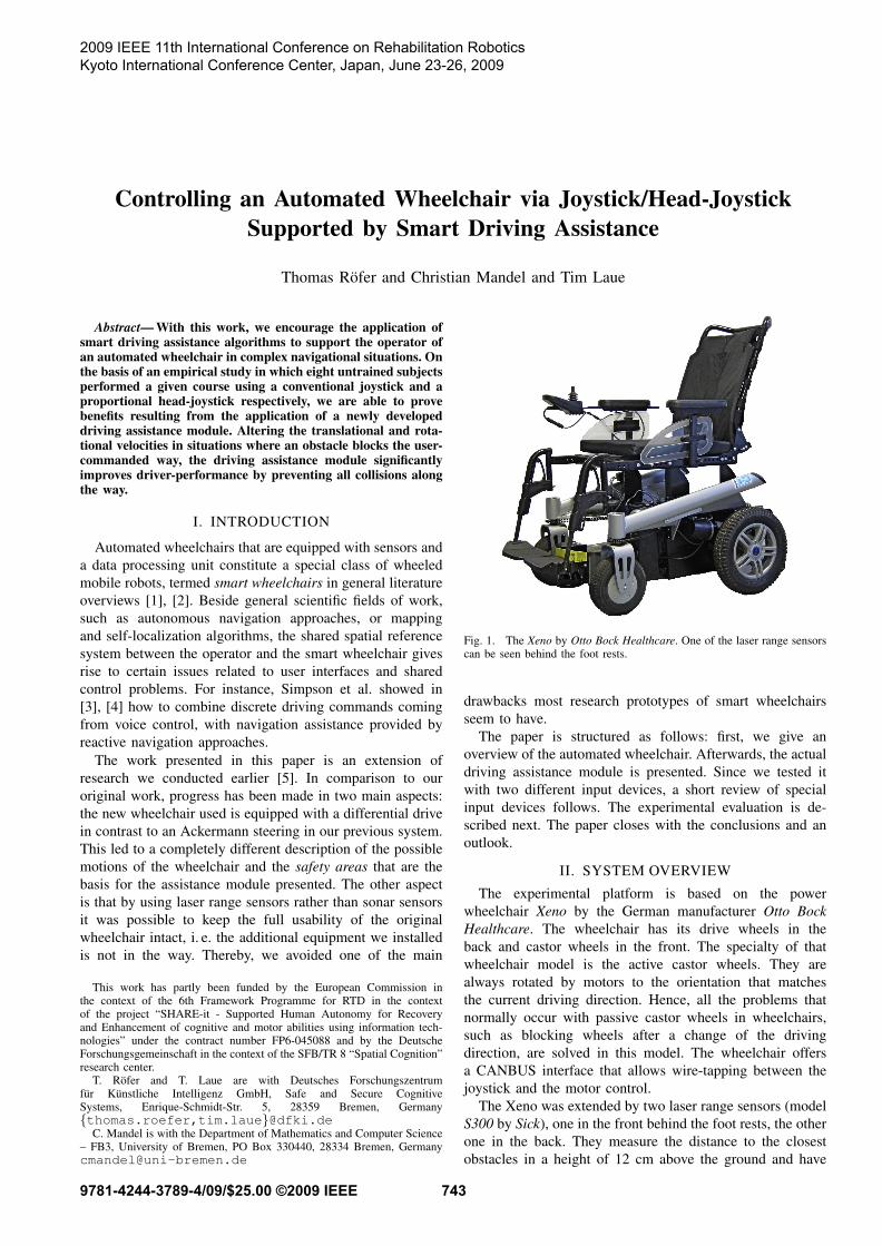
vright
vleft
Fig. 2. Some examples of safety regions for different speeds of the leftand right wheels
of the map and its border is approximately twice the length
of the overall stopping distance of the wheelchair.
B. Safety Regions
The wheelchair has a rather complex shape and the shape
of the area it “touches” during a braking maneuver is even
more complex. To effectively avoid obstacles, the knowledge
about this safety area is pertinent. The safety area depends on
dynamic and static parameters. The dynamic parameters are
the current translational and rotational driving speeds, and
their expected change due to the commands previously sent
to the wheelchair. The static parameters are the maximum
errors expected in measuring the dynamic parameters, the
shape of the actual wheelchair, the latency with which it exe-
cutes commands, its deceleration during braking maneuvers,
and the behavior of the steering while braking. In case of
the Xeno, the latter is rather interesting, because the internal
motor control of the wheelchair always turns back the active
castor wheels to “straight ahead” when a full stop command
is issued. Thereby, the Xeno breaks out of the curve it was
previously driving while braking.
Since the computation of the safety area is rather complex,
a large number of safety areas have been pre-computed and
stored in a table. The index in this table is the direction of
the vector that comprises of the dimensions left wheel speed
and right wheel speed:
φ = atan2 (vright, vleft) (1)
Thereby, any combination of translational and rotational
motion of the wheelchair can be represented, e. g., forwards,
backwards, turning on the spot, curves, etc. (cf. Fig. 2). A
safety region is represented as a set of cells, each of which
the wheelchair will reach during braking. Each cell contains
the minimum speed norm with which the wheelchair has to
drive before braking so that the cell will still be reached
during the braking maneuver. The speed norm is the sum of
the absolute values of both wheel speeds:
vnorm = |vright| + |vleft| (2)
744
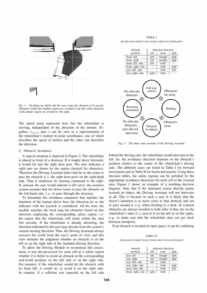
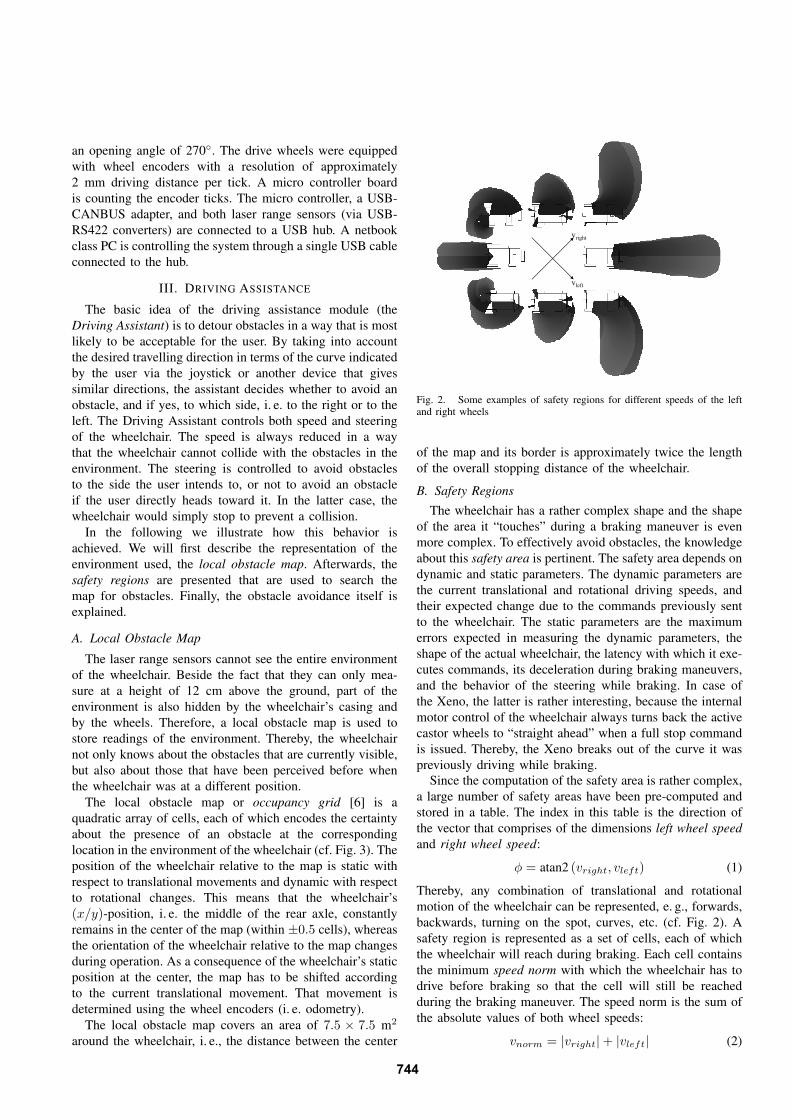
Fig. 3. Deciding on which side the user wants the obstacle to be passed.Obstacles within the brighter region are avoided to the left, while obstaclesin the darker region are avoided to the right.
The speed norm represents how fast the wheelchair is
moving, independent of the direction of the motion. To-
gether, vnorm and φ can be seen as a representation of
the wheelchair’s motion in polar coordinates, one of which
describes the speed of motion and the other one describes
the direction.
C. Obstacle Avoidance
A typical situation is depicted in Figure 3: The wheelchair
is placed in front of a doorway. If it simply drove forwards,
it would hit into the right door post. The user indicates a
right turn (as shown by the region checked for obstacles).
Therefore the Driving Assistant infers that he or she wants to
pass the obstacle (i. e. the right door post) on the right-hand
side. Thus it reinforces its steering command to the right.
If, instead, the user would indicate a left curve, the assistive
system assumes that the driver wants to pass the obstacle on
the left-hand side, i. e., to pass through the doorway.
To determine the avoidance maneuver that matches the
intention of the human driver best, the direction he or she
indicates with the joystick is considered. All the time, the
module searches the local map for obstacles based on this
direction employing the corresponding safety region, i. e.
the region that the wheelchair will reach within the next
few seconds. If the wheelchair is already detouring, the
direction indicated by the user may deviate from the system’s
current steering direction. Thus, the Driving Assistant always
assesses the world from the user’s point of view, and this
view includes the judgment whether an obstacle is on the
left or on the right side of the intended driving direction.
To allow the Driving Module to reconstruct this assess-
ment, it was pre-processed for each cell in a safety region
whether it is better to avoid an obstacle at the corresponding
real-world position on the left side or on the right side.
For instance, if the wheelchair would hit the obstacle with
its front left, it would try to avoid it on the right side.
In contrast, if a collision was expected on the left side
TABLE I
AVOIDANCE DIRECTIONS WHEN DRIVING FORWARDS
obstacle indicated directionposition left none right
front, left left straight right
front, right left straight right
front, left, side left both –
front, right, side – both right
rear, left, side – both left
rear, right, side right both –
Full user control
Braking
Obstacle avoidance
Restoring orientation
Obstaclesfar away
Obstacles
close
No relevant
obstacles,
user did not
intervene
No relevant
obstacles
Fig. 4. The finite state machine of the Driving Assistant
behind the driving axle, the wheelchair would also turn to the
left. So, the avoidance direction depends on the obstacle’s
position relative to the centre of the wheelchair’s driving
axle. The different cases are listed in Table I for forward
movements and in Table II for backward motion. Using these
decision tables, the safety regions can be enriched by the
appropriate avoidance directions for each cell of the covered
area. Figure 3 shows an example of a resulting decision
diagram. Note that if the indicated course directly points
towards an object, the Driving Assistant will not intervene
at all. This is because in such a case it is likely that the
driver’s intention is to move close to that obstacle and not
to pass around it, e. g. when docking to a desk. In contrast
obstacles are always avoided to both sides if they are on the
wheelchair’s sides (i. e. next to it on the left or on the right),
e. g., to make sure that the wheelchair does not get stuck
between doorposts.
If an obstacle is avoided in open space, it can be confusing
TABLE II
AVOIDANCE DIRECTIONS WHEN DRIVING BACKWARDS
obstacle indicated directionposition left none right
rear, left left straight right
rear, right left straight right
rear, left, side left both –
rear, right, side – both right
front, left, side – both left
front, right, side right both –
745
for the user, because the driving direction changes without
an explicit user command. Therefore, the Driving Assistant
remembers the driving direction when the avoidance ma-
neuver begins. If the user does not react to the change in
direction during the avoidance action, i. e., he or she does not
move the joystick, the system will return to the original path
indicated by the user after the obstacle was circumvented.
Therefore, a finite state machine is maintained that controls
the behavior of the wheelchair (cf. Fig. 4). As long as there
are no obstacles, the user is in full control of the vehicle.
If the obstacles are far away or the user does not wish to
avoid them, only the speed of the wheelchair is reduced.
The wheelchair will avoid an obstacle if it can determine an
avoidance direction from the direction indicated by the user
and the position of the obstacle(s). If the wheelchair passed
the obstacle and the user did not intervene by moving the
joystick, the Driving Assistant will restore the orientation
of the wheelchair. In summary, it can be stated that the user
always stays at least partially in control: the driving assistant
will never drive faster than indicated by the user, and it will
never change the driving direction (forward/backward). The
transition to automated control is seamlessly. There are no
notifications about interventions. From experiments with a
simpler system, i. e. obstacles threatening the safety regions
result in deceleration of wheel speeds, up to a full stop
maneuver, we know that notifications about obstacles that
result in a full stop of the system are sometimes desirable,
and they will be integrated in the future.
IV. USER INTERFACES
Traditional automated wheelchairs are operated by joy-
stick, directly translating the user’s hand movements into
translational and rotational velocities. While such interfaces
suit a large audience, certain disabilities may require appro-
priate alternatives, e. g. Brain-Computer-Interfaces [7], [8],
head posture [9] or gaze [10] interpretation, and natural
language communication [11], [12], to name but a few.
With regard to people needing specialized input devices
due to handicaps such as tetraplegia, this study analyzes
the impact of the proposed driving assistance module (cf.
Sec. III) on a common hand-operated joystick, and a head-
joystick (cf. Fig. 5), first described in [13], [14], [15]. While
people are familiar with the use of the former device, i.e.
the deflection of the joystick maps proportional onto the
direction and the velocities of the wheelchair, the later one
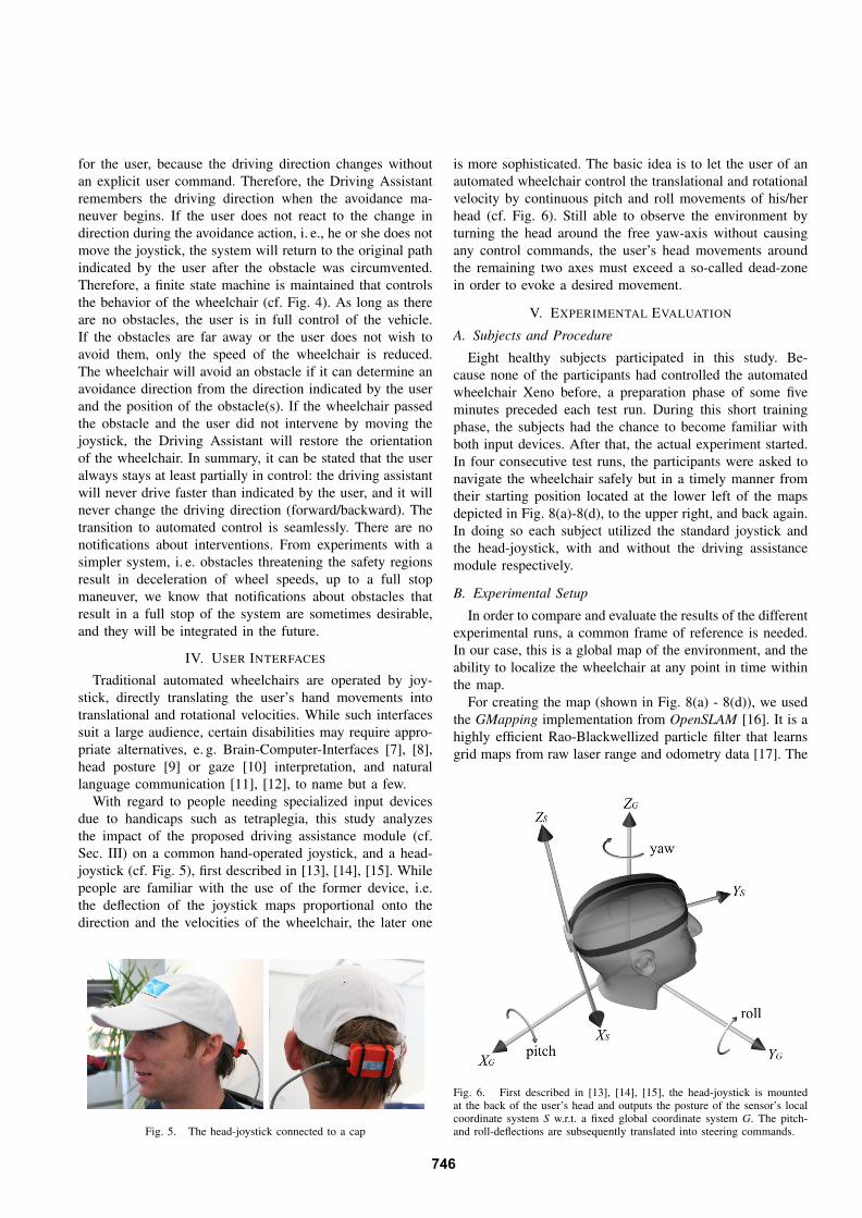
Fig. 5. The head-joystick connected to a cap
is more sophisticated. The basic idea is to let the user of an
automated wheelchair control the translational and rotational
velocity by continuous pitch and roll movements of his/her
head (cf. Fig. 6). Still able to observe the environment by
turning the head around the free yaw-axis without causing
any control commands, the user’s head movements around
the remaining two axes must exceed a so-called dead-zone
in order to evoke a desired movement.
V. EXPERIMENTAL EVALUATION
A. Subjects and Procedure
Eight healthy subjects participated in this study. Be-
cause none of the participants had controlled the automated
wheelchair Xeno before, a preparation phase of some five
minutes preceded each test run. During this short training
phase, the subjects had the chance to become familiar with
both input devices. After that, the actual experiment started.
In four consecutive test runs, the participants were asked to
navigate the wheelchair safely but in a timely manner from
their starting position located at the lower left of the maps
depicted in Fig. 8(a)-8(d), to the upper right, and back again.
In doing so each subject utilized the standard joystick and
the head-joystick, with and without the driving assistance
module respectively.
B. Experimental Setup
In order to compare and evaluate the results of the different
experimental runs, a common frame of reference is needed.
In our case, this is a global map of the environment, and the
ability to localize the wheelchair at any point in time within
the map.
For creating the map (shown in Fig. 8(a) - 8(d)), we used
the GMapping implementation from OpenSLAM [16]. It is a
highly efficient Rao-Blackwellized particle filter that learns
grid maps from raw laser range and odometry data [17]. The
Fig. 6. First described in [13], [14], [15], the head-joystick is mountedat the back of the user’s head and outputs the posture of the sensor’s localcoordinate system S w.r.t. a fixed global coordinate system G. The pitch-and roll-deflections are subsequently translated into steering commands.
746
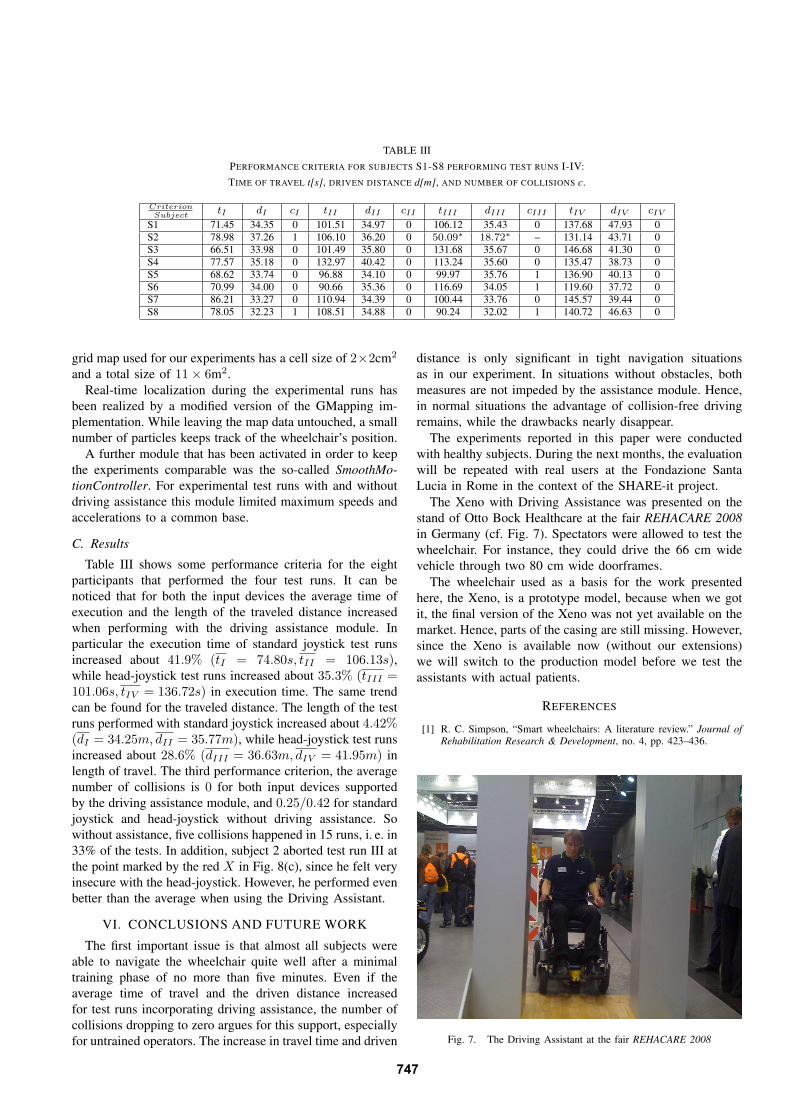
TABLE III
PERFORMANCE CRITERIA FOR SUBJECTS S1-S8 PERFORMING TEST RUNS I-IV:
TIME OF TRAVEL t[s], DRIVEN DISTANCE d[m], AND NUMBER OF COLLISIONS c.
CriterionSubject
tI dI cI tII dII cII tIII dIII cIII tIV dIV cIV
S1 71.45 34.35 0 101.51 34.97 0 106.12 35.43 0 137.68 47.93 0
S2 78.98 37.26 1 106.10 36.20 0 50.09∗
18.72∗ – 131.14 43.71 0
S3 66.51 33.98 0 101.49 35.80 0 131.68 35.67 0 146.68 41.30 0
S4 77.57 35.18 0 132.97 40.42 0 113.24 35.60 0 135.47 38.73 0
S5 68.62 33.74 0 96.88 34.10 0 99.97 35.76 1 136.90 40.13 0
S6 70.99 34.00 0 90.66 35.36 0 116.69 34.05 1 119.60 37.72 0
S7 86.21 33.27 0 110.94 34.39 0 100.44 33.76 0 145.57 39.44 0
S8 78.05 32.23 1 108.51 34.88 0 90.24 32.02 1 140.72 46.63 0
grid map used for our experiments has a cell size of 2×2cm2
and a total size of 11 × 6m2.
Real-time localization during the experimental runs has
been realized by a modified version of the GMapping im-
plementation. While leaving the map data untouched, a small
number of particles keeps track of the wheelchair’s position.
A further module that has been activated in order to keep
the experiments comparable was the so-called SmoothMo-
tionController. For experimental test runs with and without
driving assistance this module limited maximum speeds and
accelerations to a common base.
C. Results
Table III shows some performance criteria for the eight
participants that performed the four test runs. It can be
noticed that for both the input devices the average time of
execution and the length of the traveled distance increased
when performing with the driving assistance module. In
particular the execution time of standard joystick test runs
increased about 41.9% (tI = 74.80s, tII = 106.13s),while head-joystick test runs increased about 35.3% (tIII =101.06s, tIV = 136.72s) in execution time. The same trend
can be found for the traveled distance. The length of the test
runs performed with standard joystick increased about 4.42%(dI = 34.25m, dII = 35.77m), while head-joystick test runs
increased about 28.6% (dIII = 36.63m, dIV = 41.95m) in
length of travel. The third performance criterion, the average
number of collisions is 0 for both input devices supported
by the driving assistance module, and 0.25/0.42 for standard
joystick and head-joystick without driving assistance. So
without assistance, five collisions happened in 15 runs, i. e. in
33% of the tests. In addition, subject 2 aborted test run III at
the point marked by the red X in Fig. 8(c), since he felt very
insecure with the head-joystick. However, he performed even
better than the average when using the Driving Assistant.
VI. CONCLUSIONS AND FUTURE WORK
The first important issue is that almost all subjects were
able to navigate the wheelchair quite well after a minimal
training phase of no more than five minutes. Even if the
average time of travel and the driven distance increased
for test runs incorporating driving assistance, the number of
collisions dropping to zero argues for this support, especially
for untrained operators. The increase in travel time and driven
distance is only significant in tight navigation situations
as in our experiment. In situations without obstacles, both
measures are not impeded by the assistance module. Hence,
in normal situations the advantage of collision-free driving
remains, while the drawbacks nearly disappear.
The experiments reported in this paper were conducted
with healthy subjects. During the next months, the evaluation
will be repeated with real users at the Fondazione Santa
Lucia in Rome in the context of the SHARE-it project.
The Xeno with Driving Assistance was presented on the
stand of Otto Bock Healthcare at the fair REHACARE 2008
in Germany (cf. Fig. 7). Spectators were allowed to test the
wheelchair. For instance, they could drive the 66 cm wide
vehicle through two 80 cm wide doorframes.
The wheelchair used as a basis for the work presented
here, the Xeno, is a prototype model, because when we got
it, the final version of the Xeno was not yet available on the
market. Hence, parts of the casing are still missing. However,
since the Xeno is available now (without our extensions)
we will switch to the production model before we test the
assistants with actual patients.
REFERENCES
[1] R. C. Simpson, “Smart wheelchairs: A literature review.” Journal of
Rehabilitation Research & Development, no. 4, pp. 423–436.
Fig. 7. The Driving Assistant at the fair REHACARE 2008
747
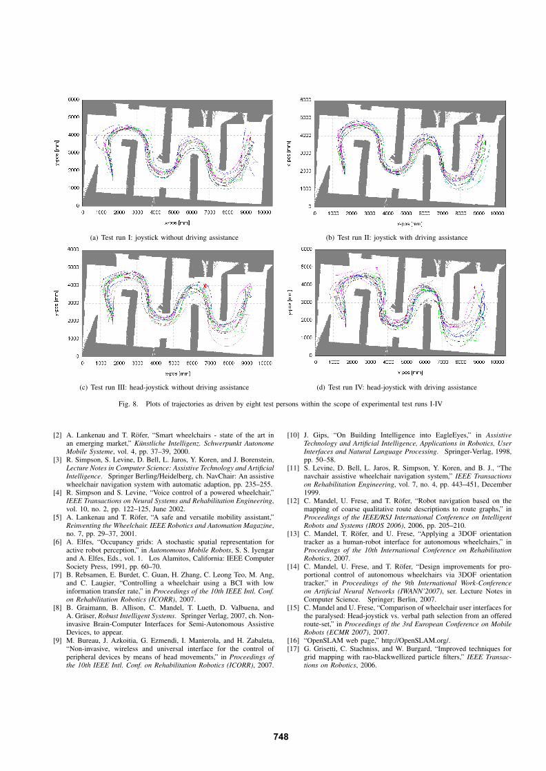
(a) Test run I: joystick without driving assistance (b) Test run II: joystick with driving assistance
(c) Test run III: head-joystick without driving assistance (d) Test run IV: head-joystick with driving assistance
Fig. 8. Plots of trajectories as driven by eight test persons within the scope of experimental test runs I-IV
[2] A. Lankenau and T. Rofer, “Smart wheelchairs - state of the art inan emerging market,” Kunstliche Intelligenz. Schwerpunkt Autonome
Mobile Systeme, vol. 4, pp. 37–39, 2000.[3] R. Simpson, S. Levine, D. Bell, L. Jaros, Y. Koren, and J. Borenstein,
Lecture Notes in Computer Science: Assistive Technology and Artificial
Intelligence. Springer Berling/Heidelberg, ch. NavChair: An assistivewheelchair navigation system with automatic adaption, pp. 235–255.
[4] R. Simpson and S. Levine, “Voice control of a powered wheelchair,”IEEE Transactions on Neural Systems and Rehabilitation Engineering,vol. 10, no. 2, pp. 122–125, June 2002.
[5] A. Lankenau and T. Rofer, “A safe and versatile mobility assistant,”Reinventing the Wheelchair. IEEE Robotics and Automation Magazine,no. 7, pp. 29–37, 2001.
[6] A. Elfes, “Occupancy grids: A stochastic spatial representation foractive robot perception,” in Autonomous Mobile Robots, S. S. Iyengarand A. Elfes, Eds., vol. 1. Los Alamitos, California: IEEE ComputerSociety Press, 1991, pp. 60–70.
[7] B. Rebsamen, E. Burdet, C. Guan, H. Zhang, C. Leong Teo, M. Ang,and C. Laugier, “Controlling a wheelchair using a BCI with lowinformation transfer rate,” in Proceedings of the 10th IEEE Intl. Conf.
on Rehabilitation Robotics (ICORR), 2007.[8] B. Graimann, B. Allison, C. Mandel, T. Lueth, D. Valbuena, and
A. Graser, Robust Intelligent Systems. Springer Verlag, 2007, ch. Non-invasive Brain-Computer Interfaces for Semi-Autonomous AssistiveDevices, to appear.
[9] M. Bureau, J. Azkoitia, G. Ezmendi, I. Manterola, and H. Zabaleta,“Non-invasive, wireless and universal interface for the control ofperipheral devices by means of head movements,” in Proceedings of
the 10th IEEE Intl. Conf. on Rehabilitation Robotics (ICORR), 2007.
[10] J. Gips, “On Building Intelligence into EagleEyes,” in Assistive
Technology and Artificial Intelligence, Applications in Robotics, User
Interfaces and Natural Language Processing. Springer-Verlag, 1998,pp. 50–58.
[11] S. Levine, D. Bell, L. Jaros, R. Simpson, Y. Koren, and B. J., “Thenavchair assistive wheelchair navigation system,” IEEE Transactions
on Rehabilitation Engineering, vol. 7, no. 4, pp. 443–451, December1999.
[12] C. Mandel, U. Frese, and T. Rofer, “Robot navigation based on themapping of coarse qualitative route descriptions to route graphs,” inProceedings of the IEEE/RSJ International Conference on Intelligent
Robots and Systems (IROS 2006), 2006, pp. 205–210.[13] C. Mandel, T. Rofer, and U. Frese, “Applying a 3DOF orientation
tracker as a human-robot interface for autonomous wheelchairs,” inProceedings of the 10th International Conference on Rehabilitation
Robotics, 2007.[14] C. Mandel, U. Frese, and T. Rofer, “Design improvements for pro-
portional control of autonomous wheelchairs via 3DOF orientationtracker,” in Proceedings of the 9th International Work-Conference
on Artificial Neural Networks (IWANN’2007), ser. Lecture Notes inComputer Science. Springer; Berlin, 2007.
[15] C. Mandel and U. Frese, “Comparison of wheelchair user interfaces forthe paralysed: Head-joystick vs. verbal path selection from an offeredroute-set,” in Proceedings of the 3rd European Conference on Mobile
Robots (ECMR 2007), 2007.[16] “OpenSLAM web page,” http://OpenSLAM.org/.[17] G. Grisetti, C. Stachniss, and W. Burgard, “Improved techniques for
grid mapping with rao-blackwellized particle filters,” IEEE Transac-
tions on Robotics, 2006.
748