Embed Size (px)
Citation preview

CONTROLLER REALIZATION OF AN INDUSTRIAL CASCADE
LEVEL SYSTEM
MOHD HAFIZ BIN SULAIMAN
22 APRIL 2009
i
CONTROLLER REALIZATION OF AN INDUSTRIAL CASCADE LEVEL SYSTEM
MOHD HAFIZ BIN SULAIMAN
B010610100
This Report Is Submitted In Partial Fulfillment of Requirements for the Degree of
Bachelor in Electrical Engineering (Mechatronics)
Faculty of Electrical Engineering
Universiti Teknikal Malaysia Melaka (UTeM).
APRIL 2009
ii
“I hereby declared that this PSM report is a result of my own work, as clearly stated in
the sources of reverences and sources is explained and stated.”
Signature : ………………………………………………
Name : MOHD HAFIZ BIN SULAIMAN
Ic / No : 850112-03-5939
Date : ……………………………………………….

iii
“I hereby declared that I have read through this report and found that it has comply
the partial fulfillment for awarding the degree of Bachelor of Mechatronics Engineering”
Signature : ………………………………………………
Supervisor’s Name : Mr. Muhammad Nizam B. Kamarudin
Date : ……………………………………………….

iv
ACKNOWLEDGEMENT
Alhamdullillah, Praise be Upon Him, The Most Compassionate and Gracious.
Throughout the period of accomplishing this project, I had received ideas, supports and
assistance from few individuals. Firstly, I would like to express my sincere appreciation to my
project’s supervisor, Mr. Muhammad Nizam Bin Kamarudin for his guidance, patience and
motivation. I am also very thankful to other my lecture that gives for their advices, guidance
and experience sharing. Without all of their continued support and interest, this project would
not have been the same as presented here.
I am also indebted to Librarians of Universiti Teknikal Malaysia Melaka (UTeM) for
their assistance in supplying the beneficial relevant literatures.
I would like also to convey my thanks to my fellow postgraduate friends whom I shall
name a few, Izzuwan, Fahmi, and others for their support at various occasions. Most
importantly, I would like to convey my special deepest thanks to my parents who had
persistently giving spiritual motivation and inspiration throughout the course of the project.
With their concern and support, I managed to motivate myself to overcome problems occurred
in this project.
Lastly for all my friend, I sincerely to appreciate their supportive, bright ideas valuable
suggestions to helping me in completing this report.
Thanks you.
v
ABSTRAK
Industri petrokimia, industri pembuatan kertas, dan lain-lain merupakan industri utama
dimana kawalan aras cecair dan arus adalah penting. Lazimnya, cecair-cecair itu akan diproses
secara rawatan kimia atau pencampuran dalam tangki tetapi selalunya aras cecair dalam tangki
tersebut perlu dikawal. Nama untuk projek ini “Controller Realization an Industrial Cascade
Level System”. “Industrial Cascade Level System” biasanya digunakan banyak dalam
kawalan proses untuk kawalan, sebagai contoh, tahap cecair dalam sebuah tangki. Sistem itu
mengandungi sebuah tangki air, satu pam air, satu “ultrasonic sensor”, menggunakan NI USB-
6009 sebagai pengawal, dan satu injap solenoid. Objektif utama projek inimencipta sistem
kawalan aras cecair menggunakan NI USB-6009 untuk mengawal sistem, juga mengenalpasti
pengesan-pengesan yang sesuai dan transduser yang digunakan untuk “Industrial Cascade
Level System”. “Cascade Level System” uk mengawal air dalam tangki pada tahap yang
diingini menggunakan NI USB 6009 kad Pemerolehan Data sebagai pengawal dan
menggunakan penderia aras ultrasonik untuk mengukur air pada paras yang diingini. Sistem
ini disambung dengan perisian LABVIEW. Pada Perisian LABVIEW akan muncul antara
muka untuk permulaan sistem itu. Apabila sistem itu dimulakan cecair akan memasuki tangki
menggunakan sebuah pam, cecair daripada tangki takungan akan menyedut oleh pam dan
cecair akan memasuki untuk tangki 1. Keperluan dalam sistem ini adalah bagi mengawal
kadar cecair dihantar oleh pam supaya tahap cecair dalam tangki adalah pada paras yang
dingini. Satu voltan malar akan diaplikasikan pam supaya satu kadar malar cecair dapat dipam
untuk tangki. Ketinggian isi cecair tangki akan kemudian akan diukur dan diplot. Selepas
menggunakan suatu model ini bagi sistem, pengawal sesuai akan direka bentuk untuk
mengawal isi air tangki. Untuk mengawal pam dan penderia aras kita menggunakan NI USB-
6009 untuk bertindak seperti satu pengawal.
vi
ABSTRACT
Industries such as petro-chemical industries, paper making industries, waste
management and others are the vital industries where liquid level and flow control are
essential. Liquids will be processed by chemical or mixing treatment in the tanks, but always
the level fluid in the tanks must be controlled. The title for this project is Controller
Realization of an Industrial Cascade Level System. Industrial cascade level systems are
commonly used in many process control applications to control, for example, the level of
liquid in a tank. The system consists of a water tank, a water pump, an ultrasonic level sensor,
a controller using NI USB-6009, and valve. The main objective this project is to design liquid
level control system using NI USB-6009 for control this system, also identify suitable sensors
and transducers used for industrial cascade level system. The industrial cascade level system
to control the water in tank at desired level using NI USB 6009 Data Acquisition card as
controller and the using ultrasonic level sensor to measure level water that desired. This
system is jointed with LABVIEW software. The LABVIEW software will appear the interface
for the start the system. When the system is start liquid enters the tank using a pump, liquid
from the reservoir tank will inhale by pump and liquid will enter to tank. The requirement in
this system is to control the rate of liquid delivered by the pump so that the level of liquid
within the tank is at the desired point. A constant voltage will be applied to the pump so that a
constant rate of liquid can be pumped to the tank. The height of the liquid inside the tank will
then be measured and plotted. A simple model of the system can then be derived from this
response curve. After obtaining a model of the system, a suitable controller will be designed to
control the level of the water inside the tank. To control pump and level sensor we use NI
USB-6009 to act as a controller.
vii
TABLE OF CONTENT
CHAPTER TITLE PAGE
TITLE i
PAGE OF ADMISSION ii
SUPERVISOR CONFIRMATION iii
ACKNOWLEDGEMENT iv
ABSTRACT v
ABSTRAK vi
TABLE OF CONTENT vii
LIST OF TABLE xi
LIST OF FIGURE xii
1 INTRODUCTION 1
1.1 Overview 1
1.2 Problem Statement 2
1.3 Objective of Project 4
1.4 Scope of Project 4
viii
2 LITERATURE REVIEW 10
2.1 Overview 10
2.2 Neuro-Fuzzy Controller Couple Tank System 11
2.3 Application Controller in Couple Tank System 11
2.4 Application PID Controller on Liquid Level Tank 12
2.5 Bienne Remote Liquid Level Control 13
2.6 Industrial Cascade Level System First Planning 15
2.6.1 Abstract 15
2.6.2 Objective 15
3 METHODOLOGY AND MATERIAL 16
3.1 Overview of Project 16
3.2 Planning of Project 16
3.3 Overall Hardware Part Project Flow 18
3.4 Project Design 19
3.5 Hardware Development 20
3.6 Component Industrial Cascade Level System 21
3.6.1 Data Acquisition Card (DAQ Card) 21
3.6.2 National Instrument USB 6009 Card 22
3.6.2.1 Connection USB 6009 to PC 24
3.6.3 Relay 29
3.6.4 Ultrasonic Sensor 30
ix
3.6.5 Solenoid Valve 35
3.6.6 Pump 37
3.7 Google Sketch 38
3.8 LABVIEW Software 39
3.9 Project Schedule (Gantt chart) 42
4 RESULT AND ANALYSIS 43
4.1 Expected Result 43
4.2 Dynamic of System 44
4.3 Tank 1 45
4.4 Tank 2 46
4.5 Reservoir Tank 47
4.6 Wiring of Circuit 48
4.7 Ultrasonic Level Sensor 49
4.7.1 Range Full Scale 50
4.7.2 Range Zero 50
4.7.3 Zero Offset 50
4.7.4 4mA Output Current 50
4.7.5 20mA Output Current 50
4.7.6 Calibration Procedure 51
4.8 Sensor Calibration 51
4.9 Interface LABVIEW Software 53

x
4.10 Flow Chart System Processing 54
5 DISCUSSION 56
6 CONCLUSION AND FUTURE RECOMMENDATION 58
REFERENCES 60
ATTACHMENT 62
xi
LIST OF TABLES
TABLE TITLE PAGE
3.1 Analog Terminal Assignment 26
3.2 Digital Terminal Assignment 27
3.3 Signal Description for USB 6009 28
3.4 Coil Data Chart 29
3.5 Contact Rating 30
3.6 Description of the Sensor Function 33
3.7 LED Display / Analogue Output 35
xii
LIST OF FIGURE
FIGURE TITLE PAGE
1.1 Industrial Cascade Level System 6
1.2 Design of Liquid Level Digital Control System Using Google
Sketch Software (FRONT VIEW) 7
1.3 Design of Liquid Level Digital Control System Using
Google Sketch Software (BACK VIEW) 8
1.4 Design of Liquid Level Digital Control System Using
Google Sketch Software (PERSPECTIVE VIEW) 9
2.1 Pump Station and Irrigation Systems Monitoring 14
2.2 Controller Realization of an Industrial Cascade Level
System (First Model) 15
3.1 Integrate Hardware and Software 18
3.2 Project Flow Chart 19
3.3 Design of Circuit Cascade Level System 20
3.4 Circuit after Done Construct 21
3.5 National Instrument USB 6009 Data Acquisition card 22
xiii
3.6 NI USB-6009 Signal Labels 23
3.7 Signal Label Application Diagram 24
3.8 The USB 6009 Connected to the Computer 25
3.9 Relay 30
3.10 Ultrasonic Sensor 31
3.11 Dimension of Ultrasonic Sensor 32
3.12 LED Window 33
3.13 RS 232- Connection 34
3.14 Function Button of Solenoid Valve 36
3.15 Solenoid Valve 37
3.16 Bullet Submersible Pump 38
3.17 Google Sketch Software 39
3.18 LABVIEW Software 41
3.19 Project Planning Schedule 42
4.1 System for Reference Dynamic of System 45
4.2 Tank 1 46
4.3 Tank 2 47
4.4 Reservoir Tank 47
4.5 Design of Circuit 48
4.6 Circuit of Industrial Cascade Level System 49
4.7 Ultrasonic Sensor Calibration 52

xiv
4.8 LABVIEW Interface 53
4.9 Flow Chart System Processing 55
1
CHAPTER 1
INTRODUCTION
1.1 Overview
Nowadays, the process industries such as petro-chemical industries, paper making and
water treatment industries require liquids to be pumped, stored in tanks, and then pumped to
another tank. The control of liquid in tanks and flow between tanks is a basic problem in the
process industries. The above mentioned industries are the vital industries where liquid level
and flow control are essential. Many times the liquids will be processed by chemical or mixing
treatment in the tanks, but always the level fluid in the tanks must be controlled, and the flow
between tanks must be regulated. Level and flow control in tanks are the heart of all chemical
engineering systems.
The title for this project is Controller Realization of an Industrial Cascade Level
System. Industrial cascade level systems are commonly used in many process control
applications to control, for example, the level of liquid in a tank. The system consists of a
water tank, a water pump, an ultrasonic level sensor, a controller using NI USB-6009, and
valve. The main objective this project is to design liquid level control system using NI USB-
6009 for control this system, also identify suitable sensors and transducers used for industrial
cascade level system.

2
Automatic control with industrial cascade level system is a useful tool in many fields
and it is also learned by the students in majors of biotechnology, industrial and chemical
engineering, besides the automation related majors in some universities. Automatic control
cascade level system laboratory is needed for the students to have a deeper and more complete
understanding of control system design and implementation, but it will be of high cost and
need more hours of course time. In order to lower the cost and save the course time, an
internet based industrial cascade level system will be constructed, which will enable the
students to conduct the control experiment at any time using a remote computer that is
connected to the internet.
The industrial cascade level system to control the water in tank at desired level using
NI USB 6009 Data Acquisition card as controller and the using ultrasonic level sensor to
measure level water that desired. This system is jointed with LABVIEW software. The
LABVIEW software will appear the interface for the start the system. When the system is start
liquid enters the tank using a pump, liquid from the reservoir tank will inhale by pump and
liquid will enter to tank. The requirement in this system is to control the rate of liquid
delivered by the pump so that the level of liquid within the tank is at the desired point. A
constant voltage will be applied to the pump so that a constant rate of liquid can be pumped to
the tank. The height of the liquid inside the tank will then be measured and plotted. A simple
model of the system can then be derived from this response curve. After obtaining a model of
the system, a suitable controller will be designed to control the level of the water inside the
tank. To control pump and level sensor we use NI USB-6009 to act as a controller.
1.2 Problem Statement
The problem statement on this project firstly is liquid level sensor in industries are
expensive and then application and demand on the use liquid level sensor in industries now is
increasing. If liquid level sensor which were relatively cheaper produce it would be able soften
the blow consumer. In now hard industry to get liquid level sensor can keep tank liquid level
on one level that the desired. We design liquid level control system to obtain exactly measure
liquid in tank.
3
The foremost important step before formulating a controller, a mathematical
relationship or the governing dynamics between the input and the output of the system should
be known. The underlying principle and knowledge of the system should be investigated to
comprehend the occurrence of nonlinearity in the system dynamics. There are wide arrays of
control techniques that can be applied to meet the control objective of the system and these
depend on the factors of which the proposed design objective might rely on. There are factors
such as tracking, reducing the effects of adverse conditions and uncertainty, behaviors in terms
of time response (e.g., stability, a certain rise-time, overshoot, and steady state tracking error)
and lastly engineering goals such as cost and reliability which is vital in industrial perspective.
Sophistication of controller scheme primarily depends on the degree of how the
nonlinearity can be tolerated and assumed using the linearization theory. Moreover, apart from
nonlinearities, there may be a consequence of unknown parameters which hinders the
objective to obtain a complete detail model of a process available for control purpose. The
factors that abstained many researchers to use conventional control theory and techniques can
be listed as follows:-
Systems are nonlinear and may contain unknown parameters. That unknown
parameters may not be estimated accurately if reliable experimental data is absent.
The delays present in the process of system (cascade level system specifically) might
complicate achieving high performance control.
There are several cases such as that of liquid level digital control tank in industry
where the process or disturbance characteristics are changing continuously. This
requires simultaneous regulation of various variables in order to maintain the desired
liquid level. Thus, a model must account for all of the most significant variables of the
process.
Due to the above mentioned factors, it might be difficult to formulate a control strategy
based on the analytical model because the mathematical model is usually linearised to account
for complexity and nonlinearity which are inevitable in a complicated system. PID
(proportional-integral-derivative) control is one of a kind of control scheme that uses the
approach of linearised model. However, the PID controller might not capable to satisfy the
control objectives or requirement at all times as it need to be regularly tuned due to the
4
varying system dynamics. Hence, it is desirable to have a robust and reliable control technique
for modeling the complex and nonlinear system that prevails in all industrial process.
1.3 Objective of Project
Fabricate Industrial Cascade Level System
To design Industrial Cascade Level System using a NI USB-6009 as controller.
Design Industrial Cascade Level System part using Google Sketch software, from
this software we can look this project with 3D view.
Develop control in LABVIEW software to control rate of water in the tank using
the controller.
Measure of liquid in the tank at a desired level. Ultrasonic level sensor will
determine a level liquid that desired.
Using a NI USB-6009 as controller and the LABVIEW software will related with
the controller.
1.4 Scope of Project
The purpose of this project is measure liquid in the tank a desired level, along with
develop and validate a mathematical dynamic model that represents the cascade level system
apparatus. This project use NI USB-6009 to control pump and also controls ultrasonic level
sensor to gauge liquid in tank at a desired level.
Then, after the models are approved of its validity, simulation will be performed using
engineering simulation software like LABVIEW to simulate its dynamic characteristic using
the actual plant parameters obtained from laboratory. A test was performed on the nonlinear
model of the cascade tank system by simulation to observe various important dynamic
characteristics at different operating conditions (water level). This is to investigate the
behavior of the system at certain range of operating conditions and thus, will give a guideline
in the development of a reference model for the system to track.
5
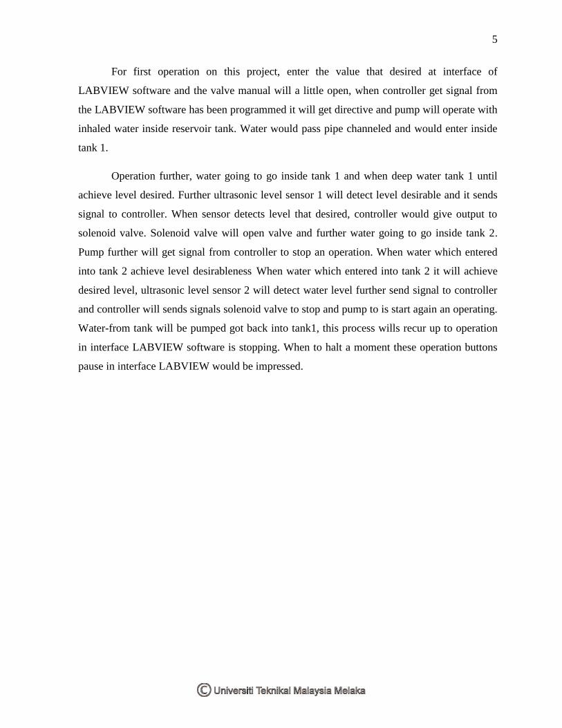
For first operation on this project, enter the value that desired at interface of
LABVIEW software and the valve manual will a little open, when controller get signal from
the LABVIEW software has been programmed it will get directive and pump will operate with
inhaled water inside reservoir tank. Water would pass pipe channeled and would enter inside
tank 1.
Operation further, water going to go inside tank 1 and when deep water tank 1 until
achieve level desired. Further ultrasonic level sensor 1 will detect level desirable and it sends
signal to controller. When sensor detects level that desired, controller would give output to
solenoid valve. Solenoid valve will open valve and further water going to go inside tank 2.
Pump further will get signal from controller to stop an operation. When water which entered
into tank 2 achieve level desirableness When water which entered into tank 2 it will achieve
desired level, ultrasonic level sensor 2 will detect water level further send signal to controller
and controller will sends signals solenoid valve to stop and pump to is start again an operating.
Water-from tank will be pumped got back into tank1, this process wills recur up to operation
in interface LABVIEW software is stopping. When to halt a moment these operation buttons
pause in interface LABVIEW would be impressed.
6
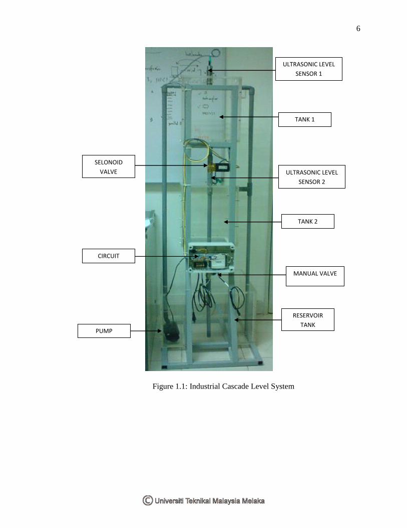
Figure 1.1: Industrial Cascade Level System
ULTRASONIC LEVEL
SENSOR 1
TANK 1
TANK 2
SELONOID
VALVE
CIRCUIT
PUMP
RESERVOIR
TANK
ULTRASONIC LEVEL
SENSOR 2
MANUAL VALVE
7
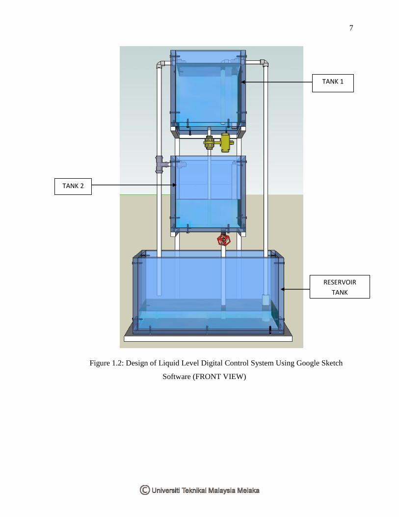
Figure 1.2: Design of Liquid Level Digital Control System Using Google Sketch
Software (FRONT VIEW)
TANK 1
TANK 2
RESERVOIR
TANK
8
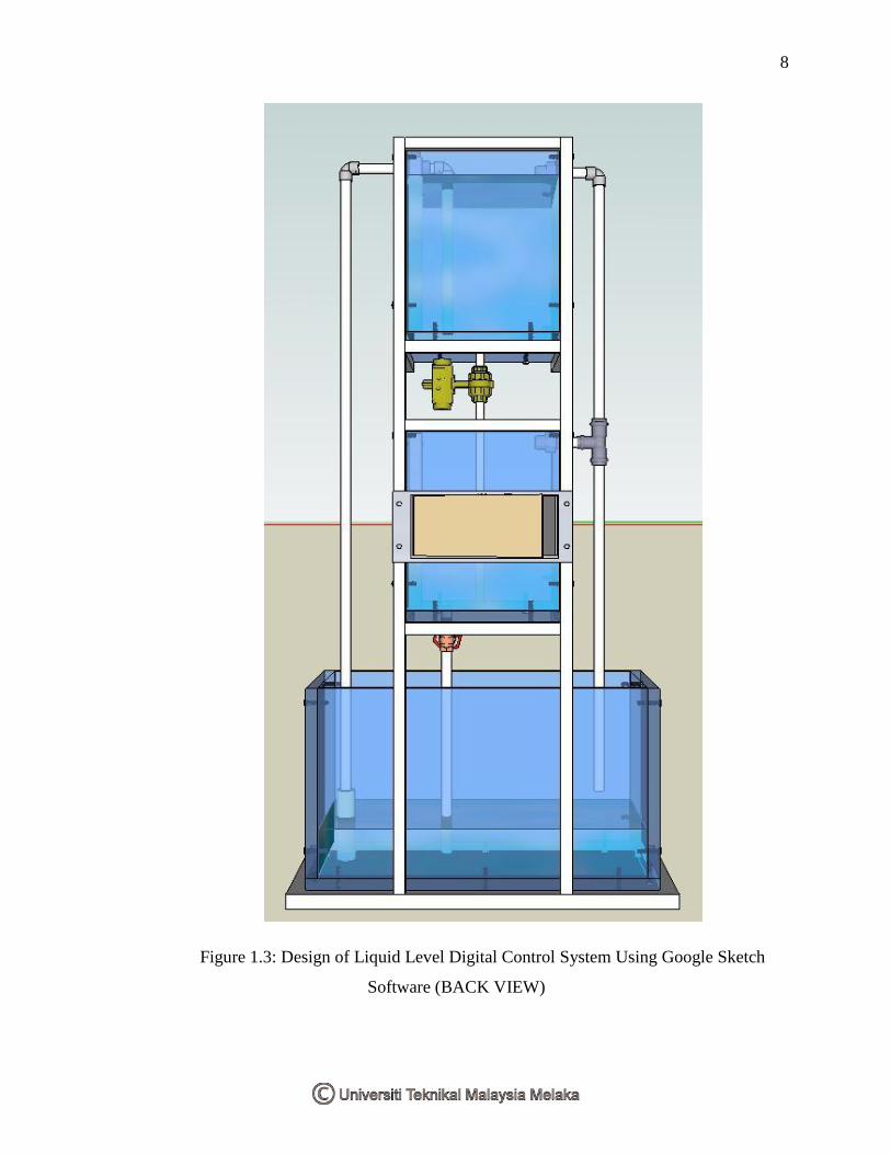
Figure 1.3: Design of Liquid Level Digital Control System Using Google Sketch
Software (BACK VIEW)
9
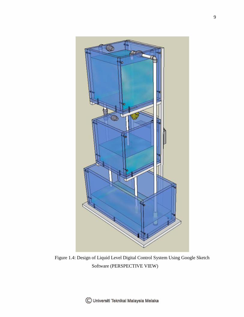
Figure 1.4: Design of Liquid Level Digital Control System Using Google Sketch
Software (PERSPECTIVE VIEW)