Embed Size (px)
Citation preview
1
Controller Installation and
Adjustment Procedures For Models
If further assistance with the following procedures is required, please
contact Snorkel’s Technical Service Department at 800-255-0317.
March18, 2010 rev A
0172326
0112567
IP-A11071
2
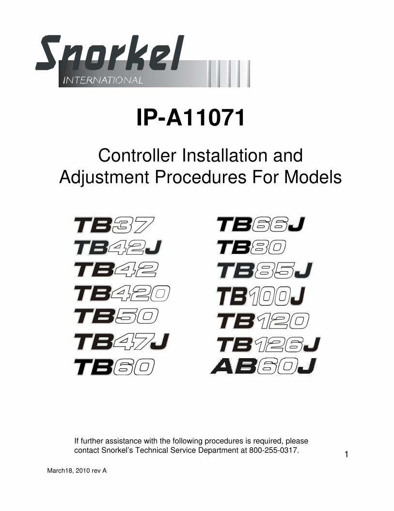
New Circuit Board Installation on Old Style Controller Housing
Remove the two screws
from the cover plate. Set
cover plate aside.
Remove the two screws
from the cover plate. Set
cover plate aside.
Remove the two screws
from the cover plate. Set
cover plate aside.
Unplug pot
connecdtor from
circuit board.
Remove the wire connectors from
each of the two micro switches.
Remove the two screws from the circuit
board mounting brackets and set screws to
one side as they will be needed for the
mounting of the new circuit board.
Remove the two screws from the circuit
board mounting brackets and set screws to
one side as they will be needed for the
mounting of the new circuit board.
Remove old
circuit board
and set aside.
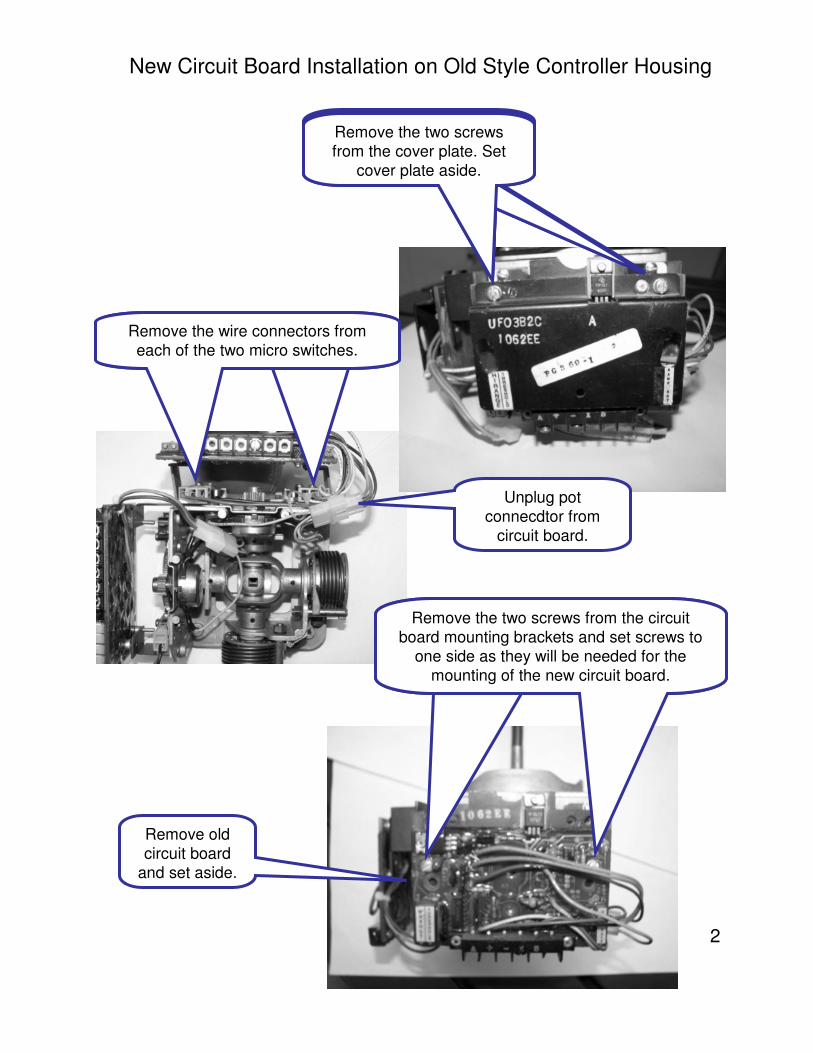
3See Controller Adjustment Procedure for final adjustments of new circuit board.
New Circuit Board Installation on Old Style Controller Housing
Using the two saved mounting screws, align the two outer holes
on the bottom of the new circuit board with the two holes on the mounting brackets. Secure new circuit board as shown.
Re connect pot connector to
new circuit board as shown.
Plug connector with
the red and black
wires in as shown.
Note: You will have one unused
micro switch after the installation
of the new circuit board.
4
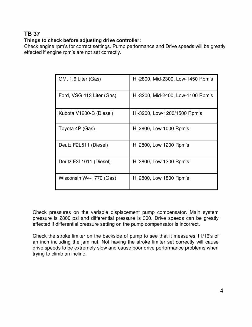
Hi 2800, Low 1800 Rpm'sWisconsin W4-1770 (Gas)
Hi 2800, Low 1300 Rpm'sDeutz F3L1011 (Diesel)
Hi 2800, Low 1200 Rpm'sDeutz F2L511 (Diesel)
Hi 2800, Low 1000 Rpm'sToyota 4P (Gas)
Hi-3200, Low-1200/1500 Rpm’sKubota V1200-B (Diesel)
Hi-3200, Mid-2400, Low-1100 Rpm’sFord, VSG 413 Liter (Gas)
Hi-2800, Mid-2300, Low-1450 Rpm’sGM, 1.6 Liter (Gas)
TB 37Things to check before adjusting drive controller:
Check engine rpm’s for correct settings. Pump performance and Drive speeds will be greatly effected if engine rpm’s are not set correctly.
Check pressures on the variable displacement pump compensator. Main system pressure is 2800 psi and differential pressure is 300. Drive speeds can be greatly
effected if differential pressure setting on the pump compensator is incorrect.
Check the stroke limiter on the backside of pump to see that it measures 11/16's of
an inch including the jam nut. Not having the stroke limiter set correctly will cause drive speeds to be extremely slow and cause poor drive performance problems when
trying to climb an incline.
5
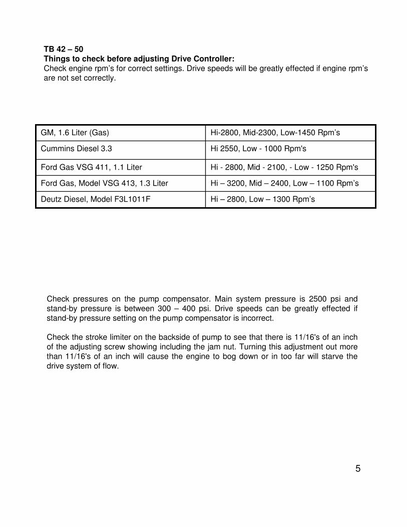
TB 42 – 50
Things to check before adjusting Drive Controller:
Check engine rpm’s for correct settings. Drive speeds will be greatly effected if engine rpm’sare not set correctly.
Check pressures on the pump compensator. Main system pressure is 2500 psi and
stand-by pressure is between 300 – 400 psi. Drive speeds can be greatly effected if
stand-by pressure setting on the pump compensator is incorrect.
Check the stroke limiter on the backside of pump to see that there is 11/16's of an inch
of the adjusting screw showing including the jam nut. Turning this adjustment out more
than 11/16's of an inch will cause the engine to bog down or in too far will starve the
drive system of flow.
Hi – 2800, Low – 1300 Rpm’sDeutz Diesel, Model F3L1011F
Hi – 3200, Mid – 2400, Low – 1100 Rpm’sFord Gas, Model VSG 413, 1.3 Liter
Hi - 2800, Mid - 2100, - Low - 1250 Rpm'sFord Gas VSG 411, 1.1 Liter
Hi 2550, Low - 1000 Rpm'sCummins Diesel 3.3
Hi-2800, Mid-2300, Low-1450 Rpm’sGM, 1.6 Liter (Gas)
6
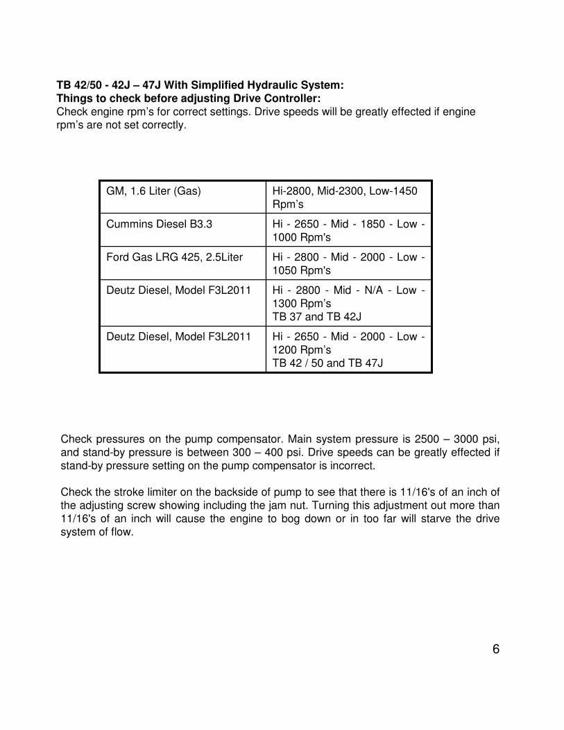
TB 42/50 - 42J – 47J With Simplified Hydraulic System:
Things to check before adjusting Drive Controller:
Check engine rpm’s for correct settings. Drive speeds will be greatly effected if enginerpm’s are not set correctly.
Check pressures on the pump compensator. Main system pressure is 2500 – 3000 psi,
and stand-by pressure is between 300 – 400 psi. Drive speeds can be greatly effected if
stand-by pressure setting on the pump compensator is incorrect.
Check the stroke limiter on the backside of pump to see that there is 11/16's of an inch of
the adjusting screw showing including the jam nut. Turning this adjustment out more than
11/16's of an inch will cause the engine to bog down or in too far will starve the drive
system of flow.
Hi - 2650 - Mid - 2000 - Low -
1200 Rpm’s
TB 42 / 50 and TB 47J
Deutz Diesel, Model F3L2011
Hi - 2800 - Mid - N/A - Low -
1300 Rpm’s
TB 37 and TB 42J
Deutz Diesel, Model F3L2011
Hi - 2800 - Mid - 2000 - Low -
1050 Rpm's
Ford Gas LRG 425, 2.5Liter
Hi - 2650 - Mid - 1850 - Low -
1000 Rpm's
Cummins Diesel B3.3
Hi-2800, Mid-2300, Low-1450
Rpm’s
GM, 1.6 Liter (Gas)
7
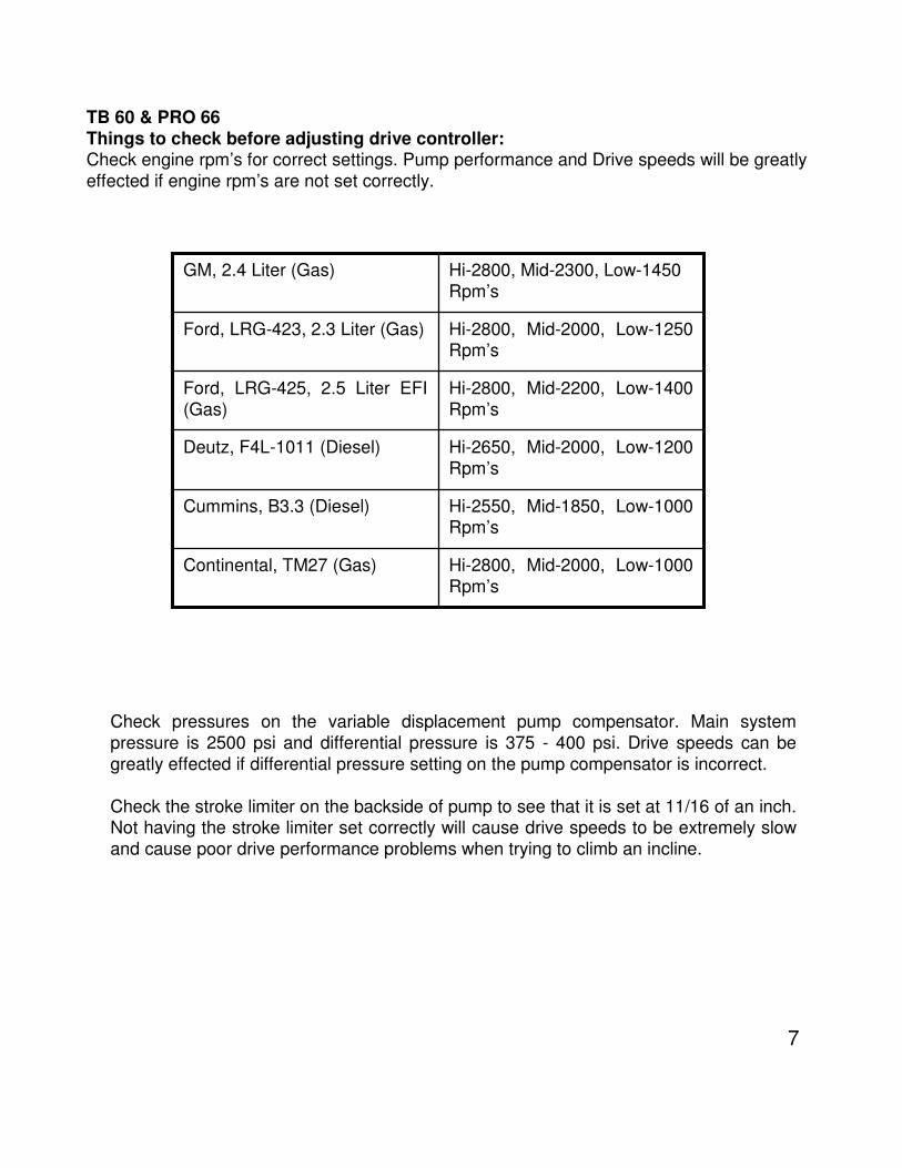
TB 60 & PRO 66
Things to check before adjusting drive controller:Check engine rpm’s for correct settings. Pump performance and Drive speeds will be greatly
effected if engine rpm’s are not set correctly.
Check pressures on the variable displacement pump compensator. Main system
pressure is 2500 psi and differential pressure is 375 - 400 psi. Drive speeds can be
greatly effected if differential pressure setting on the pump compensator is incorrect.
Check the stroke limiter on the backside of pump to see that it is set at 11/16 of an inch. Not having the stroke limiter set correctly will cause drive speeds to be extremely slow
and cause poor drive performance problems when trying to climb an incline.
Hi-2800, Mid-2000, Low-1000
Rpm’s
Continental, TM27 (Gas)
Hi-2550, Mid-1850, Low-1000 Rpm’s
Cummins, B3.3 (Diesel)
Hi-2650, Mid-2000, Low-1200
Rpm’s
Deutz, F4L-1011 (Diesel)
Hi-2800, Mid-2200, Low-1400
Rpm’s
Ford, LRG-425, 2.5 Liter EFI
(Gas)
Hi-2800, Mid-2000, Low-1250 Rpm’s
Ford, LRG-423, 2.3 Liter (Gas)
Hi-2800, Mid-2300, Low-1450
Rpm’s
GM, 2.4 Liter (Gas)
8
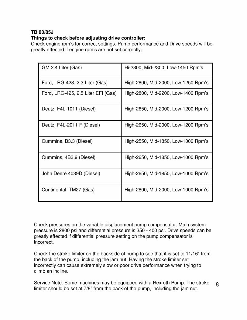
TB 80/85J
Things to check before adjusting drive controller:Check engine rpm’s for correct settings. Pump performance and Drive speeds will be
greatly effected if engine rpm’s are not set correctly.
Check pressures on the variable displacement pump compensator. Main system pressure is 2800 psi and differential pressure is 350 - 400 psi. Drive speeds can be
greatly effected if differential pressure setting on the pump compensator is
incorrect.
Check the stroke limiter on the backside of pump to see that it is set to 11/16” from the back of the pump, including the jam nut. Having the stroke limiter set
incorrectly can cause extremely slow or poor drive performance when trying to
climb an incline.
Service Note: Some machines may be equipped with a Rexroth Pump. The stroke
limiter should be set at 7/8” from the back of the pump, including the jam nut.
High-2800, Mid-2000, Low-1000 Rpm’sContinental, TM27 (Gas)
High-2650, Mid-1850, Low-1000 Rpm’sJohn Deere 4039D (Diesel)
High-2650, Mid-1850, Low-1000 Rpm’sCummins, 4B3.9 (Diesel)
High-2550, Mid-1850, Low-1000 Rpm’sCummins, B3.3 (Diesel)
High-2650, Mid-2000, Low-1200 Rpm’sDeutz, F4L-2011 F (Diesel)
High-2650, Mid-2000, Low-1200 Rpm’sDeutz, F4L-1011 (Diesel)
High-2800, Mid-2200, Low-1400 Rpm’sFord, LRG-425, 2.5 Liter EFI (Gas)
High-2800, Mid-2000, Low-1250 Rpm’sFord, LRG-423, 2.3 Liter (Gas)
Hi-2800, Mid-2300, Low-1450 Rpm’sGM 2.4 Liter (Gas)
9
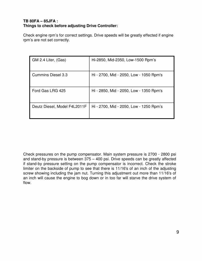
TB 80FA – 85JFA :Things to check before adjusting Drive Controller:
Check engine rpm’s for correct settings. Drive speeds will be greatly effected if engine rpm’s are not set correctly.
Check pressures on the pump compensator. Main system pressure is 2700 - 2800 psi
and stand-by pressure is between 375 – 400 psi. Drive speeds can be greatly affected
if stand-by pressure setting on the pump compensator is incorrect. Check the stroke
limiter on the backside of pump to see that there is 11/16's of an inch of the adjusting screw showing including the jam nut. Turning this adjustment out more than 11/16's of
an inch will cause the engine to bog down or in too far will starve the drive system of
flow.
Hi - 2700, Mid - 2050, Low - 1050 Rpm'sCummins Diesel 3.3
Hi - 2850, Mid - 2050, Low - 1350 Rpm'sFord Gas LRG 425
Hi - 2700, Mid - 2050, Low - 1250 Rpm’sDeutz Diesel, Model F4L2011F
Hi-2850, Mid-2350, Low-1500 Rpm’sGM 2.4 Liter, (Gas)
10
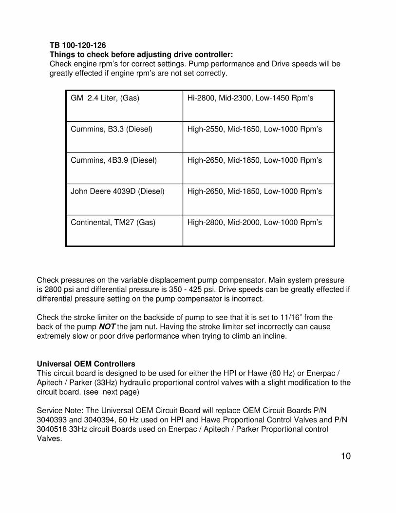
TB 100-120-126 Things to check before adjusting drive controller:
Check engine rpm’s for correct settings. Pump performance and Drive speeds will be
greatly effected if engine rpm’s are not set correctly.
Check pressures on the variable displacement pump compensator. Main system pressure
is 2800 psi and differential pressure is 350 - 425 psi. Drive speeds can be greatly effected if
differential pressure setting on the pump compensator is incorrect.
Check the stroke limiter on the backside of pump to see that it is set to 11/16” from the back of the pump NOT the jam nut. Having the stroke limiter set incorrectly can cause
extremely slow or poor drive performance when trying to climb an incline.
Universal OEM ControllersThis circuit board is designed to be used for either the HPI or Hawe (60 Hz) or Enerpac /
Apitech / Parker (33Hz) hydraulic proportional control valves with a slight modification to the
circuit board. (see next page)
Service Note: The Universal OEM Circuit Board will replace OEM Circuit Boards P/N
3040393 and 3040394, 60 Hz used on HPI and Hawe Proportional Control Valves and P/N
3040518 33Hz circuit Boards used on Enerpac / Apitech / Parker Proportional control
Valves.
High-2800, Mid-2000, Low-1000 Rpm’sContinental, TM27 (Gas)
High-2650, Mid-1850, Low-1000 Rpm’sJohn Deere 4039D (Diesel)
High-2650, Mid-1850, Low-1000 Rpm’sCummins, 4B3.9 (Diesel)
High-2550, Mid-1850, Low-1000 Rpm’sCummins, B3.3 (Diesel)
Hi-2800, Mid-2300, Low-1450 Rpm’sGM 2.4 Liter, (Gas)
11
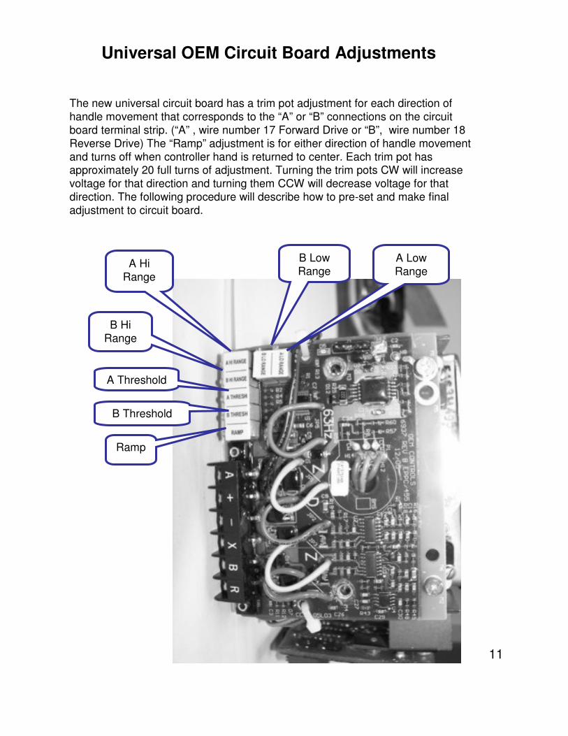
Universal OEM Circuit Board Adjustments
The new universal circuit board has a trim pot adjustment for each direction of
handle movement that corresponds to the “A” or “B” connections on the circuit
board terminal strip. (“A” , wire number 17 Forward Drive or “B”, wire number 18
Reverse Drive) The “Ramp” adjustment is for either direction of handle movement
and turns off when controller hand is returned to center. Each trim pot has approximately 20 full turns of adjustment. Turning the trim pots CW will increase
voltage for that direction and turning them CCW will decrease voltage for that
direction. The following procedure will describe how to pre-set and make final
adjustment to circuit board.
A Low
Range
B Low
RangeA Hi
Range
B Hi
Range
A Threshold
B Threshold
Ramp
12
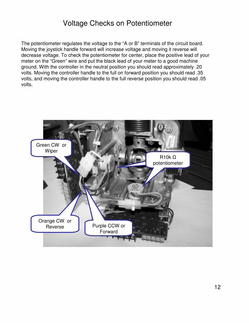
The potentiometer regulates the voltage to the “A or B” terminals of the circuit board.
Moving the joystick handle forward will increase voltage and moving it reverse will decrease voltage. To check the potentiometer for center, place the positive lead of your
meter on the “Green” wire and put the black lead of your meter to a good machine
ground. With the controller in the neutral position you should read approximately .20
volts. Moving the controller handle to the full on forward position you should read .35
volts, and moving the controller handle to the full reverse position you should read .05 volts.
Voltage Checks on Potentiometer
Purple CCW or
Forward
Orange CW or
Reverse
Green CW or
Wiper
R10k Ω
potentiometer
13
Preset Procedure for Drive Controller:
1. Turn the Ramp trim pot 20 full turns (CCW).
2. Turn the “A and B” Low Range Trim Pots CW 10 full turns.3. Place the ignition switch to on and start the engine. If machine is equipped with a Jib,
fully lower the Jib. Place the boom in its fully stowed position and fully Retract the
boom in. Turn engine off, turn key switch back on.
4. Place Drive Range switch set to Hi and Foot switch down.
5. Move the control handle off center approximately 1½”. 6. Holding that position, adjust the “Threshold for that direction “A or B” trim pots counter
CW to obtain 2.5 to 3.5 volts. Return controller handle to center.
Verify there is 12 volt on the “R”.
1. Depress the foot switch.2. Move the controller handle full on.
3. With the controller full on, adjust the “A and B” trim pots CW to obtain 7.5 to 9 volt
setting. Return controller handle to center.
Start engine and raise the boom up above horizontal. Turn engine off, and key switch back
on.
Verify there is “No” voltage on the “R” .
1. Depress the foot switch.2. Move the controller handle full on.
3. With the controller full on, Adjust the “A and B” Low Range trim pot clock wise or CCW
to obtain 4.5 to 5.5 volt setting. Return controller handle to center.
14
Drive Controller Final Adjustment:
Before starting controller adjustment, make sure that the hydraulic oil is up to operating
temperature 80°to 90°.
Mark off fifty feet. At the platform, place the Range Selector switch to “Hi”, Ignition switch on,
Throttle switch to HI. Make sure that the “R” terminal on the drive circuit board has 12 volts on
it. Start engine. Lower the boom below horizontal, lower jib boom to its stowed position and
fully retracted the boom. At a rolling start, perform the following:
Threshold: Make sure after the “A (Forward) and B (Reverse)” Hi and Low range has been
adjusted that the Threshold “A and B” both smooth starts and stops. (With controller handle
full on, move controller handle approximately 1” from full on towards the off position. The drive
function should start to slow down until handle reached approximately 1½” to center of controller or shuts off.)
See Drive Speed Chart below. Speed is achieved by adjusting the Hi and Low trim pots.3 MPH = 50’ in X Seconds (see chart, page 14)1 MPH = 50’ in X seconds (see chart, page 14)
High Range: Move the controller handle to the full on position. At a rolling start, time the
machine within the fifty feet. Adjust the Hi Range ”A (Forward) and B (Reverse)” trim pot
clockwise or counter clockwise as necessary to obtain the correct times as specified in the chart below.
Low Range or Dual Range: Elevate the boom above horizontal. Check the “R” terminal of
the drive controller to see that it does not have 12 volts on it. Move the controller handle to the
full on position. At a rolling start, time the machine within the fifty feet. Adjust the Low Range “A and B” trim pot clockwise or counter clockwise as necessary to obtain the correct times for
Forward (A) and Reverse (B) as specified in the chart below. After the Low Range adjustment,
lower the boom to its stowed position.
Ramp (Single Trim Pot): Is a time delay built into the circuit board for either the “A or B”direction. The more you turn the ramp trim pot clockwise, the more time delay you add to the
machine response to controller movement. Turning the ramp trim pot counter clockwise de-
creases ramp delay of controller response when moved. Adjust the ramp delay to achieve a 1
½ to 2 second delay.
15
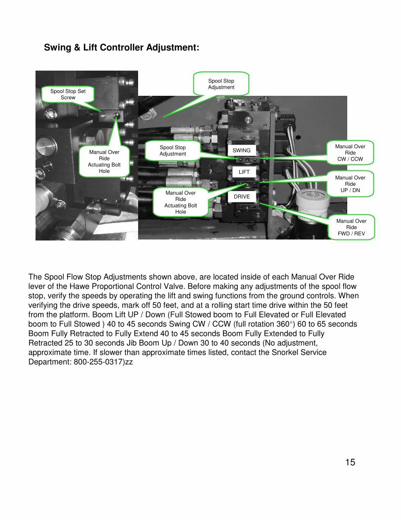
The Spool Flow Stop Adjustments shown above, are located inside of each Manual Over Ride
lever of the Hawe Proportional Control Valve. Before making any adjustments of the spool flow stop, verify the speeds by operating the lift and swing functions from the ground controls. When
verifying the drive speeds, mark off 50 feet, and at a rolling start time drive within the 50 feet
from the platform. Boom Lift UP / Down (Full Stowed boom to Full Elevated or Full Elevated boom to Full Stowed ) 40 to 45 seconds Swing CW / CCW (full rotation 360°) 60 to 65 seconds
Boom Fully Retracted to Fully Extend 40 to 45 seconds Boom Fully Extended to Fully Retracted 25 to 30 seconds Jib Boom Up / Down 30 to 40 seconds (No adjustment,
approximate time. If slower than approximate times listed, contact the Snorkel Service
Department: 800-255-0317)zz
Manual Over Ride
CW / CCW
SWING
LIFT
DRIVE
Manual Over Ride
UP / DN
Manual Over Ride
FWD / REV
Spool Stop
Adjustment
Manual Over Ride
Actuating Bolt Hole
Spool Stop Set Screw
Manual Over Ride
Actuating Bolt Hole
Spool Stop Adjustment
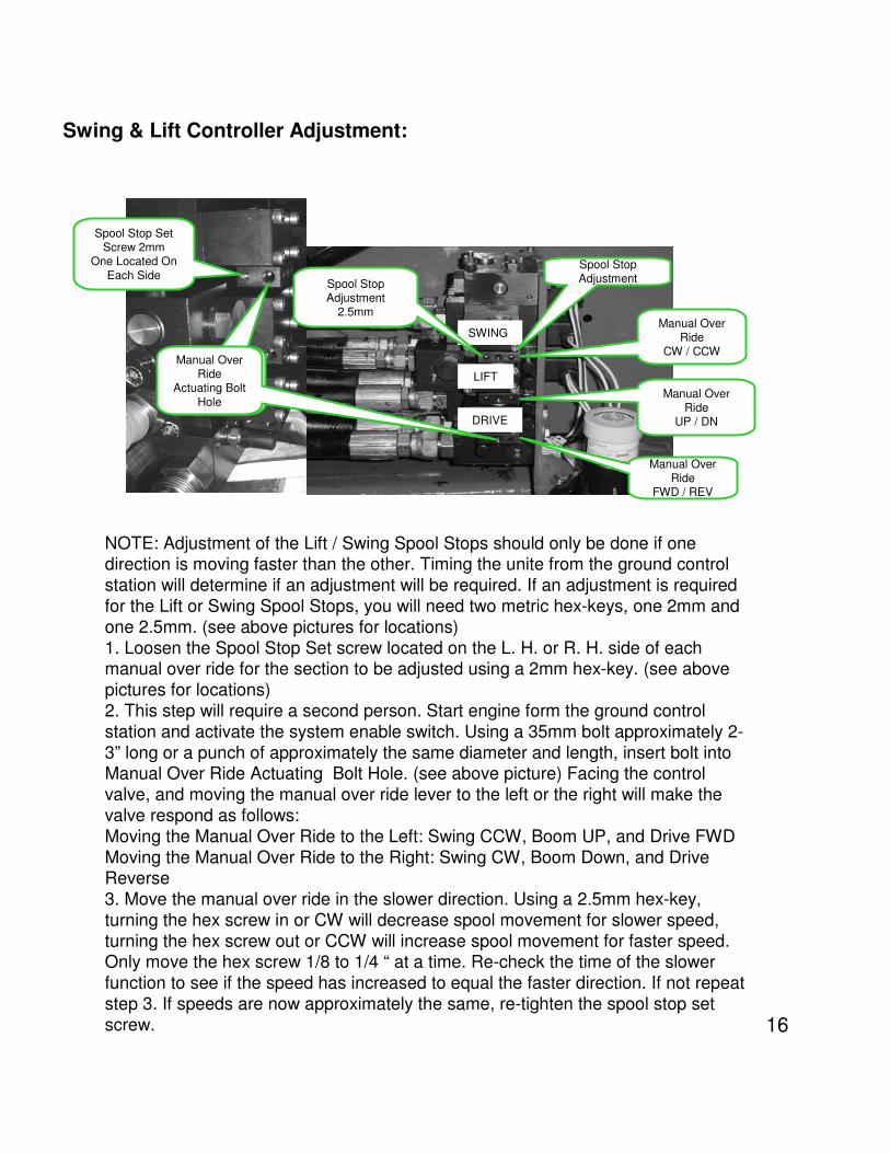
Swing & Lift Controller Adjustment:
16
NOTE: Adjustment of the Lift / Swing Spool Stops should only be done if one direction is moving faster than the other. Timing the unite from the ground control
station will determine if an adjustment will be required. If an adjustment is required
for the Lift or Swing Spool Stops, you will need two metric hex-keys, one 2mm and
one 2.5mm. (see above pictures for locations)
1. Loosen the Spool Stop Set screw located on the L. H. or R. H. side of each manual over ride for the section to be adjusted using a 2mm hex-key. (see above
pictures for locations)
2. This step will require a second person. Start engine form the ground control
station and activate the system enable switch. Using a 35mm bolt approximately 2-
3” long or a punch of approximately the same diameter and length, insert bolt into Manual Over Ride Actuating Bolt Hole. (see above picture) Facing the control
valve, and moving the manual over ride lever to the left or the right will make the
valve respond as follows:
Moving the Manual Over Ride to the Left: Swing CCW, Boom UP, and Drive FWD
Moving the Manual Over Ride to the Right: Swing CW, Boom Down, and Drive Reverse
3. Move the manual over ride in the slower direction. Using a 2.5mm hex-key,
turning the hex screw in or CW will decrease spool movement for slower speed,
turning the hex screw out or CCW will increase spool movement for faster speed. Only move the hex screw 1/8 to 1/4 “ at a time. Re-check the time of the slower
function to see if the speed has increased to equal the faster direction. If not repeat
step 3. If speeds are now approximately the same, re-tighten the spool stop set
screw.
Manual Over Ride
CW / CCW
SWING
LIFT
DRIVE
Manual Over Ride
UP / DN
Manual Over Ride
FWD / REV
Spool Stop Set Screw 2mm
One Located On
Each SideSpool Stop AdjustmentSpool Stop
Adjustment2.5mm
Manual Over Ride
Actuating Bolt
Hole
Manual Over Ride
Actuating Bolt
Hole
Swing & Lift Controller Adjustment:
17
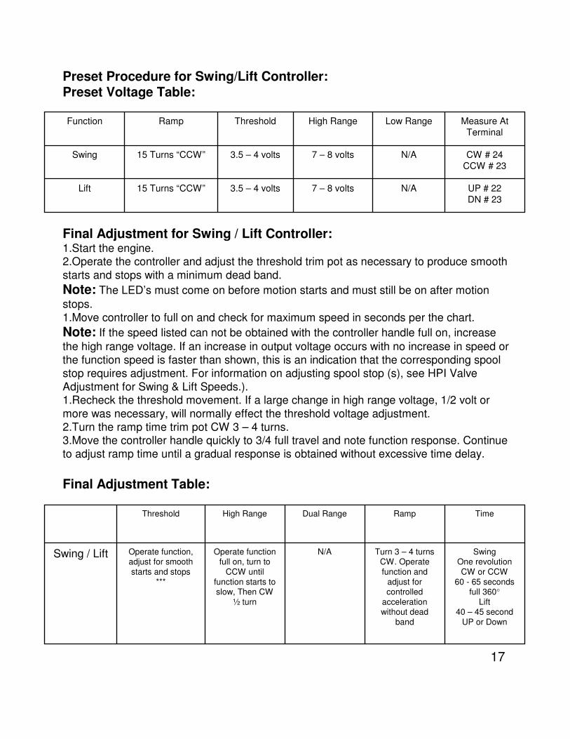
Preset Procedure for Swing/Lift Controller:Preset Voltage Table:
UP # 22
DN # 23
N/A7 – 8 volts3.5 – 4 volts15 Turns “CCW”Lift
CW # 24
CCW # 23
N/A7 – 8 volts3.5 – 4 volts15 Turns “CCW”Swing
Measure At
Terminal
Low RangeHigh RangeThresholdRampFunction
Final Adjustment for Swing / Lift Controller:1.Start the engine.2.Operate the controller and adjust the threshold trim pot as necessary to produce smooth
starts and stops with a minimum dead band.
Note: The LED’s must come on before motion starts and must still be on after motion
stops.
1.Move controller to full on and check for maximum speed in seconds per the chart.
Note: If the speed listed can not be obtained with the controller handle full on, increase
the high range voltage. If an increase in output voltage occurs with no increase in speed or
the function speed is faster than shown, this is an indication that the corresponding spool
stop requires adjustment. For information on adjusting spool stop (s), see HPI Valve
Adjustment for Swing & Lift Speeds.).1.Recheck the threshold movement. If a large change in high range voltage, 1/2 volt or
more was necessary, will normally effect the threshold voltage adjustment.
2.Turn the ramp time trim pot CW 3 – 4 turns.3.Move the controller handle quickly to 3/4 full travel and note function response. Continue
to adjust ramp time until a gradual response is obtained without excessive time delay.
Final Adjustment Table:
Swing One revolution
CW or CCW
60 - 65 secondsfull 360°
Lift40 – 45 second
UP or Down
Turn 3 – 4 turns CW. Operate
function and
adjust for controlled
acceleration without dead
band
N/AOperate function full on, turn to
CCW until
function starts to slow, Then CW
½ turn
Operate function, adjust for smooth
starts and stops
***
Swing / Lift
TimeRampDual RangeHigh RangeThreshold
18
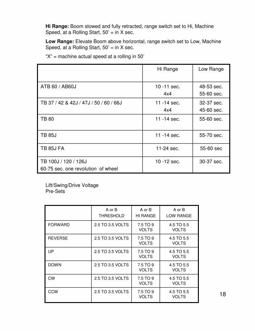
30-37 sec.10 -12 sec.TB 100J / 120 / 126J
60-75 sec. one revolution of wheel
55-60 sec11-24 sec.TB 85J FA
55-70 sec.11 -14 sec.TB 85J
55-60 sec.11 -14 sec.TB 80
32-37 sec.
45-60 sec.
11 -14 sec.
4x4
TB 37 / 42 & 42J / 47J / 50 / 60 / 66J
48-53 sec.
55-60 sec.
10 -11 sec.
4x4
ATB 60 / AB60J
Low RangeHi Range
Hi Range: Boom stowed and fully retracted, range switch set to Hi, Machine
Speed, at a Rolling Start, 50’ = in X sec.
Low Range: Elevate Boom above horizontal, range switch set to Low, Machine
Speed, at a Rolling Start, 50’ = in X sec.
“X” = machine actual speed at a rolling in 50’
4.5 TO 5.5
VOLTS
7.5 TO 9
VOLTS
2.5 TO 3.5 VOLTSCCW
4.5 TO 5.5
VOLTS
7.5 TO 9
VOLTS
2.5 TO 3.5 VOLTSCW
4.5 TO 5.5
VOLTS
7.5 TO 9
VOLTS
2.5 TO 3.5 VOLTSDOWN
4.5 TO 5.5
VOLTS
7.5 TO 9
VOLTS
2.5 TO 3.5 VOLTSUP
4.5 TO 5.5
VOLTS
7.5 TO 9
VOLTS
2.5 TO 3.5 VOLTSREVERSE
4.5 TO 5.5
VOLTS
7.5 TO 9
VOLTS
2.5 TO 3.5 VOLTSFORWARD
A or B
LOW RANGE
A or B
HI RANGE
A or B
THRESHOLD
Lift/Swing/Drive Voltage
Pre-Sets
19
SERVICE NOTES:
1. On both A and B Low Range trim pots, turn adjustment screws 10 full turns
clockwise. (On models TB 37,42,42J, 47J, 420 and 50, Low Range is not used for
Lift/Swing low speed. After preset of 10 turns on both trim pots, precede to the Hi
Range adjustment.) On these machines low is, however, used for elevated drive speeds.
2. Preset both the A and B Threshold trim pots. The controller handle must be moved at least 1½ inches off center or until machine is just barely starts to creep and adjust
per above chart.
3. Move controller handle to full on and adjust the A and B Hi Range trim pots per
above chart.
4. Elevate the boom above horizontal or extend out past 4’ for Drive/Lift/Swing. Move
controller handle full on and adjust Low range trim pot. (Low Range Trim Pot only
applies to models TB 80, 85J, TB 80, 85J FA, Lift/Swing/Drive and TB100, 120 and
126 Swing/Drive only. Remove wire #122 from “R” terminal of controller and adjust
the Low Range trim pot.)
20
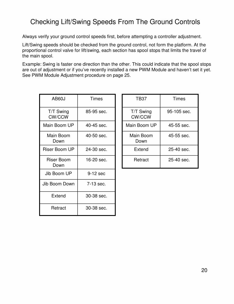
Checking Lift/Swing Speeds From The Ground Controls
Always verify your ground control speeds first, before attempting a controller adjustment.
Lift/Swing speeds should be checked from the ground control, not form the platform. At the
proportional control valve for lift/swing, each section has spool stops that limits the travel of
the main spool.
Example: Swing is faster one direction than the other. This could indicate that the spool stops
are out of adjustment or if you’ve recently installed a new PWM Module and haven’t set it yet.
See PWM Module Adjustment procedure on page 25.
85-95 sec.T/T Swing
CW/CCW
TimesAB60J
30-38 sec.Retract
30-38 sec.Extend
7-13 sec.Jib Boom Down
9-12 secJib Boom UP
16-20 sec.Riser Boom
Down
24-30 sec.Riser Boom UP
40-50 sec.Main Boom
Down
40-45 sec.Main Boom UP
95-105 sec.T/T Swing
CW/CCW
TimesTB37
25-40 sec.Retract
25-40 sec.Extend
45-55 sec.Main Boom
Down
45-55 sec.Main Boom UP
21
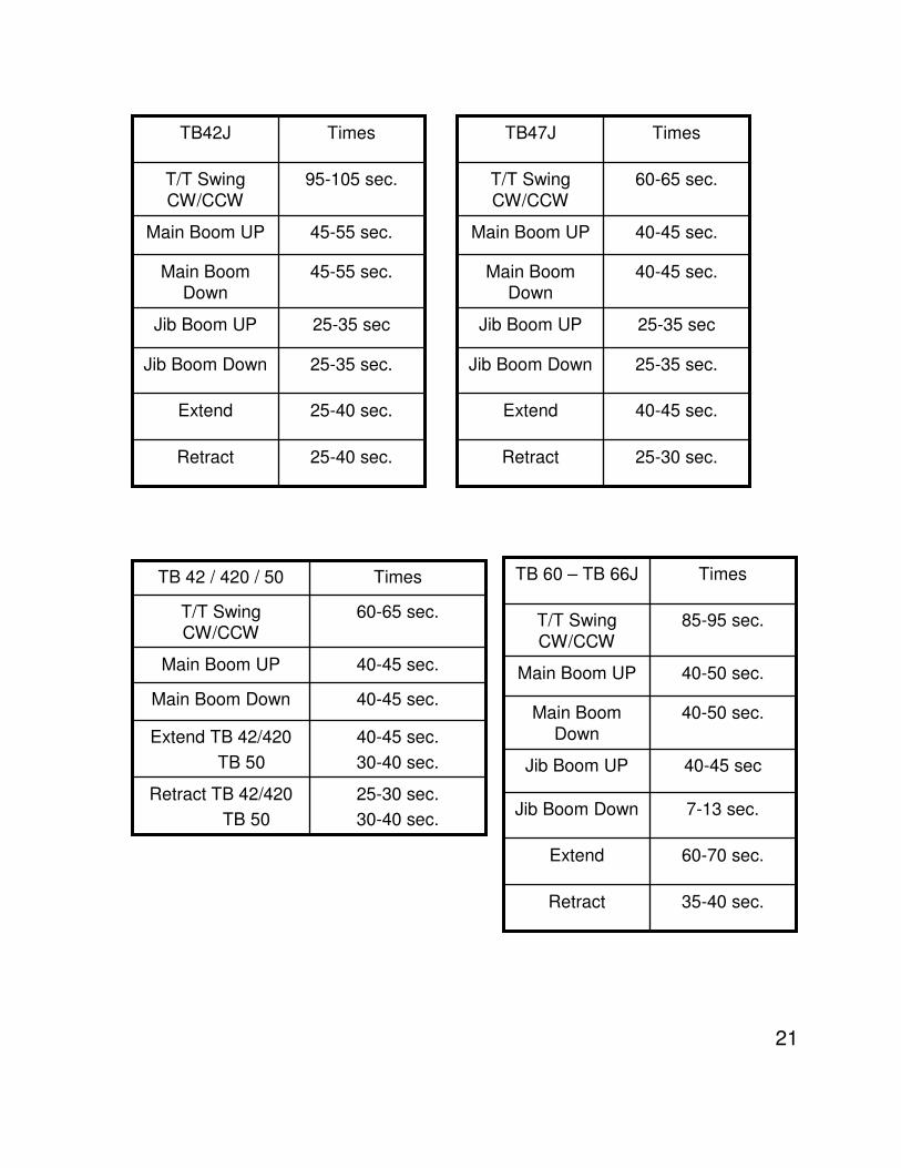
95-105 sec.T/T Swing
CW/CCW
TimesTB42J
25-40 sec.Retract
25-40 sec.Extend
25-35 sec.Jib Boom Down
25-35 secJib Boom UP
45-55 sec.Main Boom Down
45-55 sec.Main Boom UP
60-65 sec.T/T Swing
CW/CCW
TimesTB47J
25-30 sec.Retract
40-45 sec.Extend
25-35 sec.Jib Boom Down
25-35 secJib Boom UP
40-45 sec.Main Boom Down
40-45 sec.Main Boom UP
85-95 sec.T/T Swing
CW/CCW
TimesTB 60 – TB 66J
35-40 sec.Retract
60-70 sec.Extend
7-13 sec.Jib Boom Down
40-45 secJib Boom UP
40-50 sec.Main Boom
Down
40-50 sec.Main Boom UP
60-65 sec.T/T Swing CW/CCW
TimesTB 42 / 420 / 50
25-30 sec.
30-40 sec.
Retract TB 42/420
TB 50
40-45 sec.
30-40 sec.
Extend TB 42/420
TB 50
40-45 sec.Main Boom Down
40-45 sec.Main Boom UP
22
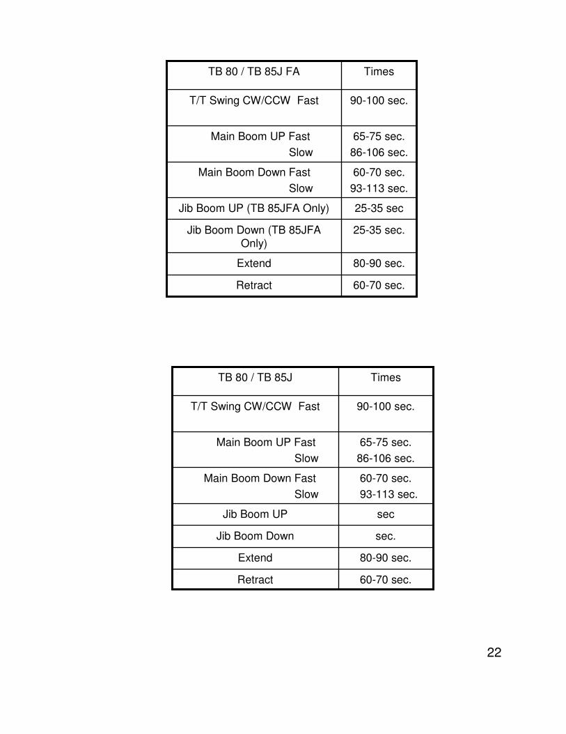
90-100 sec.T/T Swing CW/CCW Fast
TimesTB 80 / TB 85J
60-70 sec.Retract
80-90 sec.Extend
sec.Jib Boom Down
secJib Boom UP
60-70 sec.
93-113 sec.
Main Boom Down Fast
Slow
65-75 sec.
86-106 sec.
Main Boom UP Fast
Slow
90-100 sec.T/T Swing CW/CCW Fast
TimesTB 80 / TB 85J FA
60-70 sec.Retract
80-90 sec.Extend
25-35 sec.Jib Boom Down (TB 85JFA
Only)
25-35 secJib Boom UP (TB 85JFA Only)
60-70 sec.
93-113 sec.
Main Boom Down Fast
Slow
65-75 sec.
86-106 sec.
Main Boom UP Fast
Slow
23
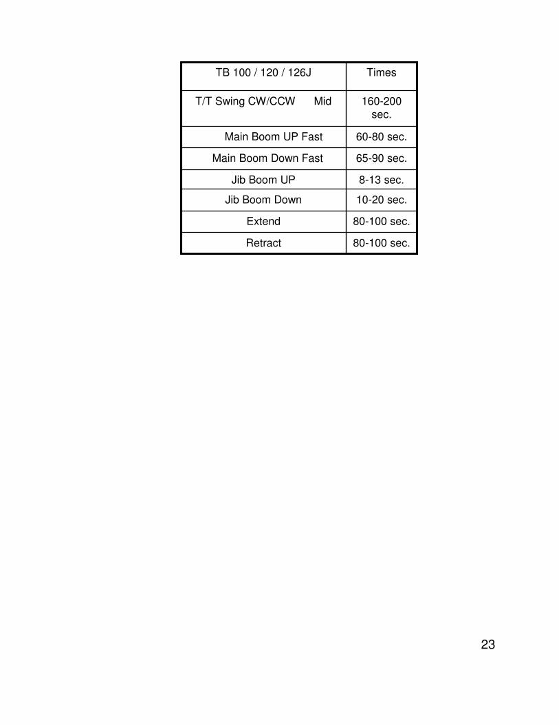
160-200
sec.
T/T Swing CW/CCW Mid
TimesTB 100 / 120 / 126J
80-100 sec.Retract
80-100 sec.Extend
10-20 sec.Jib Boom Down
8-13 sec.Jib Boom UP
65-90 sec.Main Boom Down Fast
60-80 sec.Main Boom UP Fast
24
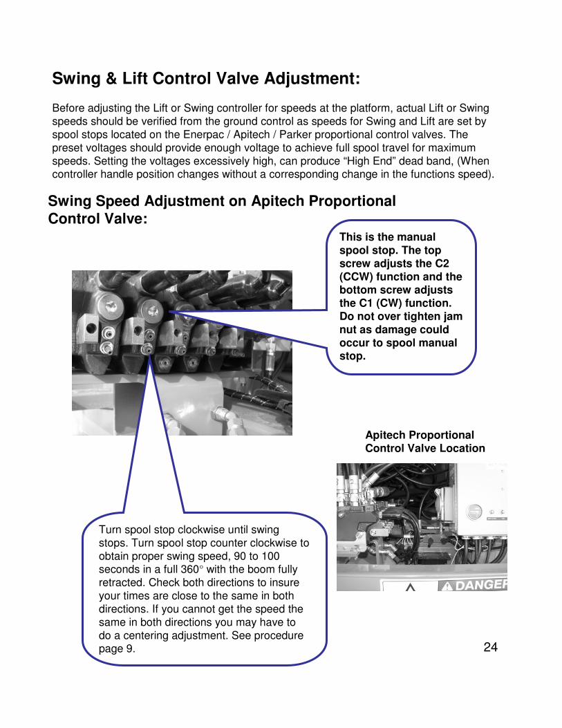
Swing & Lift Control Valve Adjustment:
Before adjusting the Lift or Swing controller for speeds at the platform, actual Lift or Swing
speeds should be verified from the ground control as speeds for Swing and Lift are set by
spool stops located on the Enerpac / Apitech / Parker proportional control valves. The
preset voltages should provide enough voltage to achieve full spool travel for maximum
speeds. Setting the voltages excessively high, can produce “High End” dead band, (When controller handle position changes without a corresponding change in the functions speed).
Swing Speed Adjustment on Apitech Proportional
Control Valve:
Apitech Proportional Control Valve Location
This is the manual
spool stop. The top screw adjusts the C2 (CCW) function and the bottom screw adjusts the C1 (CW) function. Do not over tighten jam nut as damage could occur to spool manual stop.
Turn spool stop clockwise until swing
stops. Turn spool stop counter clockwise to
obtain proper swing speed, 90 to 100 seconds in a full 360° with the boom fully
retracted. Check both directions to insure
your times are close to the same in both
directions. If you cannot get the speed the
same in both directions you may have to
do a centering adjustment. See procedure page 9.
25
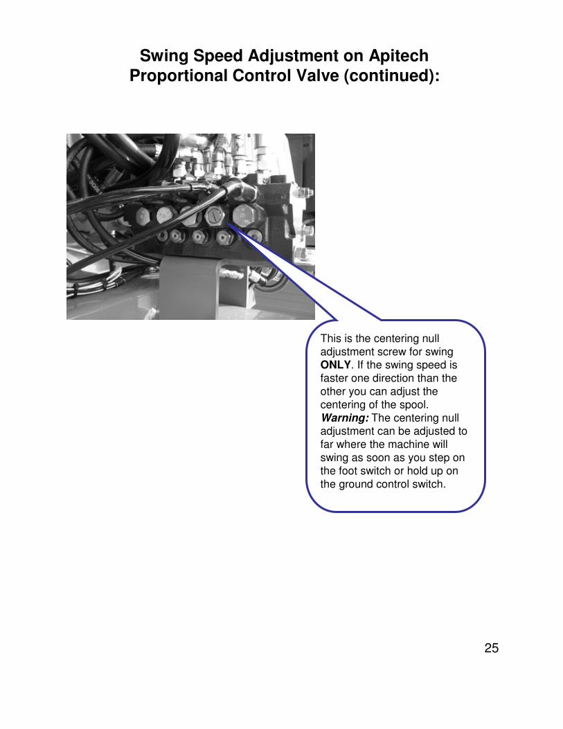
Swing Speed Adjustment on ApitechProportional Control Valve (continued):
This is the centering null
adjustment screw for swing ONLY. If the swing speed is
faster one direction than the
other you can adjust the
centering of the spool.
Warning: The centering null adjustment can be adjusted to
far where the machine will
swing as soon as you step on
the foot switch or hold up on
the ground control switch.
26
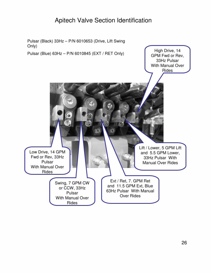
Apitech Valve Section Identification
Pulsar (Black) 33Hz – P/N 6010653 (Drive, Lift Swing
Only)
Pulsar (Blue) 63Hz – P/N 6010845 (EXT / RET Only)
Low Drive, 14 GPM
Fwd or Rev, 33Hz
Pulsar
With Manual Over Rides
Swing, 7 GPM CW
or CCW, 33Hz
Pulsar
With Manual Over Rides
Ext / Ret, 7. GPM Ret
and 11.5 GPM Ext, Blue
63Hz Pulsar With Manual
Over Rides
Lift / Lower, 5 GPM Lift
and 5.5 GPM Lower,
33Hz Pulsar With
Manual Over Rides
High Drive, 14
GPM Fwd or Rev,
33Hz Pulsar
With Manual Over Rides
27
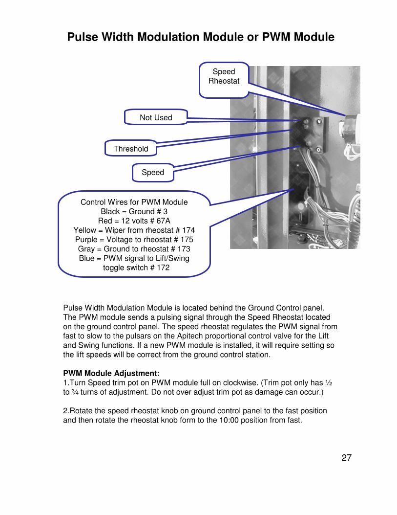
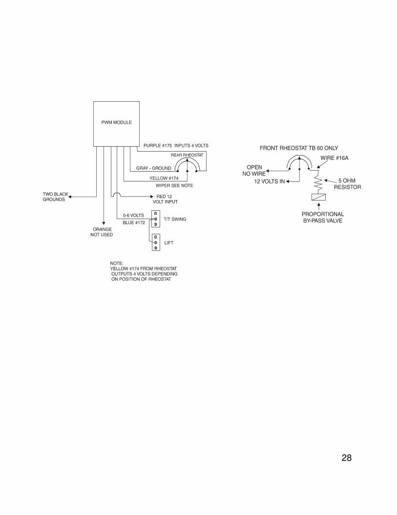
Pulse Width Modulation Module is located behind the Ground Control panel.
The PWM module sends a pulsing signal through the Speed Rheostat located
on the ground control panel. The speed rheostat regulates the PWM signal from fast to slow to the pulsars on the Apitech proportional control valve for the Lift
and Swing functions. If a new PWM module is installed, it will require setting so
the lift speeds will be correct from the ground control station.
PWM Module Adjustment:1.Turn Speed trim pot on PWM module full on clockwise. (Trim pot only has ½
to ¾ turns of adjustment. Do not over adjust trim pot as damage can occur.)
2.Rotate the speed rheostat knob on ground control panel to the fast position
and then rotate the rheostat knob form to the 10:00 position from fast.
Pulse Width Modulation Module or PWM Module
Not Used
Threshold
Speed
Control Wires for PWM Module
Black = Ground # 3Red = 12 volts # 67A
Yellow = Wiper from rheostat # 174
Purple = Voltage to rheostat # 175
Gray = Ground to rheostat # 173
Blue = PWM signal to Lift/Swingtoggle switch # 172
Speed
Rheostat
28
29
PWM Module Adjustment (continued):
3. Using the Boom Up control switch at the ground control, adjust the threshold trim pot
on PWM module until the boom just starts to move. Rotate the speed rheostat from fast
to slow checking for metering control with out excessive dead band.
4. Rotate the Speed rheostat to the Fast position. Place the boom in the fully stowed
position. Time the boom through it full range of movement. From fully stowed to fully
elevated should be 65 to 75 seconds and fully elevated to fully stowed should be 60 to
70 seconds. If lift speeds are to fast, turn the Speed trim pot counter clockwise to
decrease boom speed.
Service Tips:
Lift and Swing will not work from ground control station but will from platform.Check rheostat position
Check signal from PWM Module (#172) to Lift/Swing switches
When moving the rheostat at the ground control from fast to slow and lift or swing
stops, replace the rheostat.
The Jib function is a non-proportional function. The approximate “Lift and Lower”
times are 25 – 35 seconds.
30
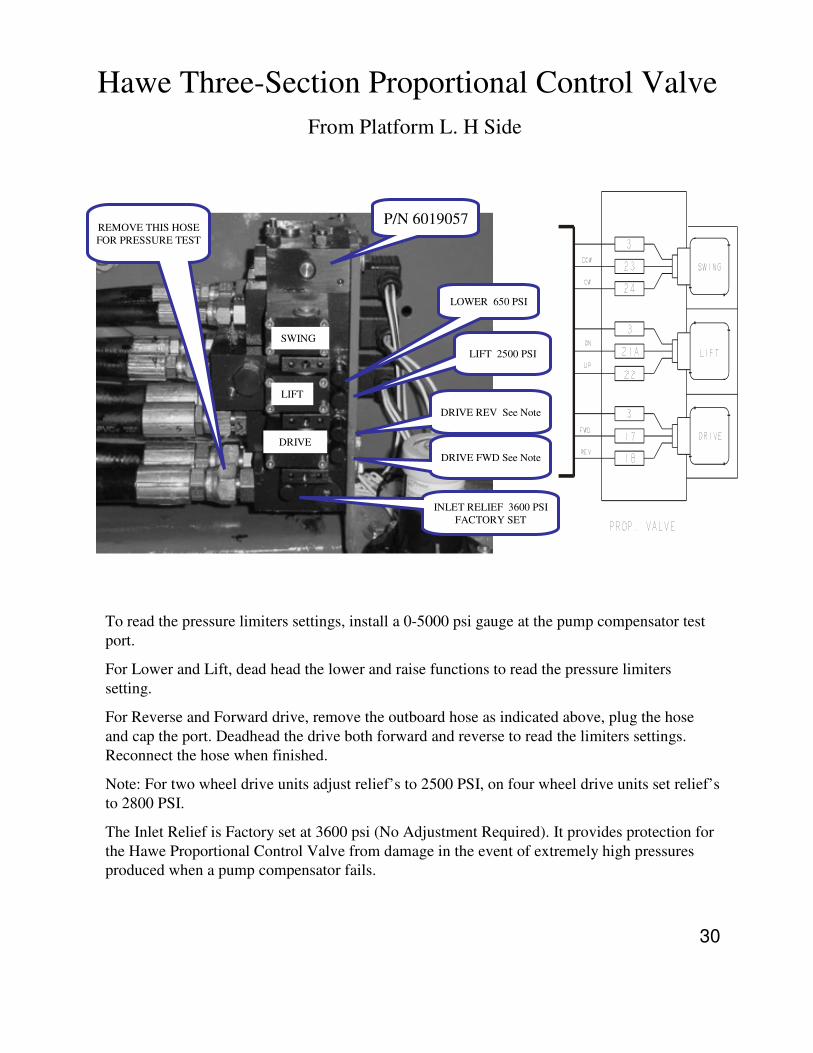
Hawe Three-Section Proportional Control Valve
From Platform L. H Side
To read the pressure limiters settings, install a 0-5000 psi gauge at the pump compensator test
port.
For Lower and Lift, dead head the lower and raise functions to read the pressure limiters
setting.
For Reverse and Forward drive, remove the outboard hose as indicated above, plug the hose
and cap the port. Deadhead the drive both forward and reverse to read the limiters settings.
Reconnect the hose when finished.
Note: For two wheel drive units adjust relief’s to 2500 PSI, on four wheel drive units set relief’s
to 2800 PSI.
The Inlet Relief is Factory set at 3600 psi (No Adjustment Required). It provides protection for
the Hawe Proportional Control Valve from damage in the event of extremely high pressures
produced when a pump compensator fails.
P/N 6019057
LOWER 650 PSI
SWING
LIFT
DRIVE
LIFT 2500 PSI
DRIVE REV See Note
DRIVE FWD See Note
INLET RELIEF 3600 PSI
FACTORY SET
REMOVE THIS HOSE
FOR PRESSURE TEST
31
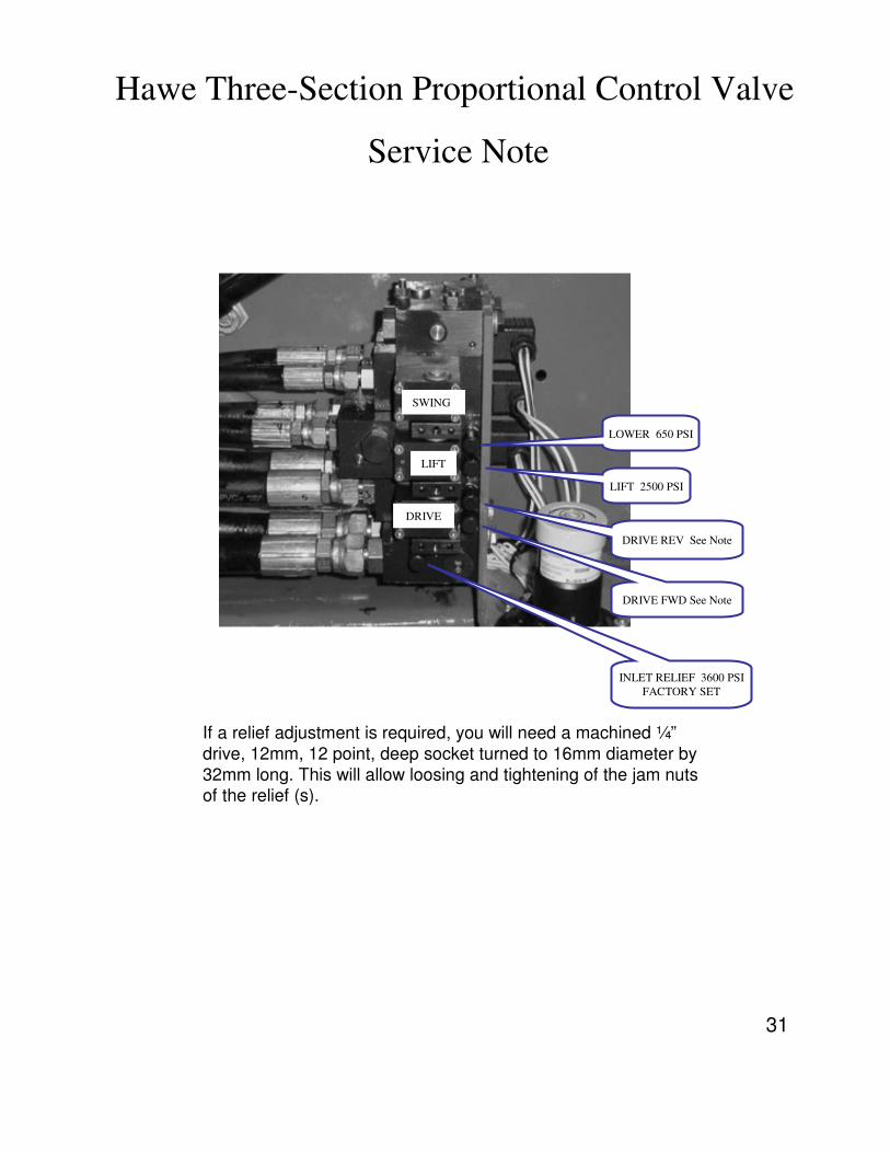
Hawe Three-Section Proportional Control Valve
Service Note
If a relief adjustment is required, you will need a machined ¼”
drive, 12mm, 12 point, deep socket turned to 16mm diameter by
32mm long. This will allow loosing and tightening of the jam nuts of the relief (s).
LOWER 650 PSI
SWING
LIFT
DRIVE
LIFT 2500 PSI
DRIVE REV See Note
DRIVE FWD See Note
INLET RELIEF 3600 PSI
FACTORY SET
32
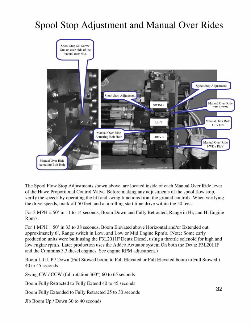
Spool Stop Adjustment and Manual Over Rides
The Spool Flow Stop Adjustments shown above, are located inside of each Manual Over Ride lever
of the Hawe Proportional Control Valve. Before making any adjustments of the spool flow stop,
verify the speeds by operating the lift and swing functions from the ground controls. When verifying
the drive speeds, mark off 50 feet, and at a rolling start time drive within the 50 feet.
For 3 MPH = 50’ in 11 to 14 seconds, Boom Down and Fully Retracted, Range in Hi, and Hi Engine
Rpm's.
For 1 MPH = 50’ in 33 to 38 seconds, Boom Elevated above Horizontal and/or Extended out
approximately 6’, Range switch in Low, and Low or Mid Engine Rpm's. (Note: Some early
production units were built using the F3L2011F Deutz Diesel, using a throttle solenoid for high and
low engine rpm,s. Later production uses the Addco Actuator system On both the Deutz F3L2011F
and the Cummins 3.3 diesel engines. See engine RPM adjustment.)
Boom Lift UP / Down (Full Stowed boom to Full Elevated or Full Elevated boom to Full Stowed )
40 to 45 seconds
Swing CW / CCW (full rotation 360°) 60 to 65 seconds
Boom Fully Retracted to Fully Extend 40 to 45 seconds
Boom Fully Extended to Fully Retracted 25 to 30 seconds
Jib Boom Up / Down 30 to 40 seconds
Manual Over Ride
CW / CCWSWING
LIFT
DRIVE
Manual Over Ride
UP / DN
Manual Over Ride
FWD / REV
Spool Stop Adjustment
Spool Stop Adjustment
Manual Over Ride
Actuating Bolt Hole
Spool Stop Set Screw
One on each side of the
manual over ride.
Manual Over Ride
Actuating Bolt Hole
33
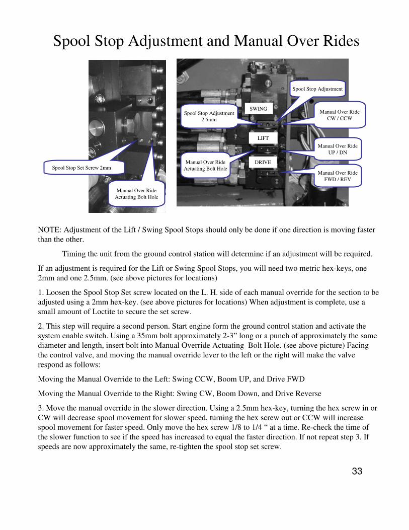
Spool Stop Adjustment and Manual Over Rides
NOTE: Adjustment of the Lift / Swing Spool Stops should only be done if one direction is moving faster
than the other.
Timing the unit from the ground control station will determine if an adjustment will be required.
If an adjustment is required for the Lift or Swing Spool Stops, you will need two metric hex-keys, one
2mm and one 2.5mm. (see above pictures for locations)
1. Loosen the Spool Stop Set screw located on the L. H. side of each manual override for the section to be
adjusted using a 2mm hex-key. (see above pictures for locations) When adjustment is complete, use a
small amount of Loctite to secure the set screw.
2. This step will require a second person. Start engine form the ground control station and activate the
system enable switch. Using a 35mm bolt approximately 2-3” long or a punch of approximately the same
diameter and length, insert bolt into Manual Override Actuating Bolt Hole. (see above picture) Facing
the control valve, and moving the manual override lever to the left or the right will make the valve
respond as follows:
Moving the Manual Override to the Left: Swing CCW, Boom UP, and Drive FWD
Moving the Manual Override to the Right: Swing CW, Boom Down, and Drive Reverse
3. Move the manual override in the slower direction. Using a 2.5mm hex-key, turning the hex screw in or
CW will decrease spool movement for slower speed, turning the hex screw out or CCW will increase
spool movement for faster speed. Only move the hex screw 1/8 to 1/4 “ at a time. Re-check the time of
the slower function to see if the speed has increased to equal the faster direction. If not repeat step 3. If
speeds are now approximately the same, re-tighten the spool stop set screw.
SWING
LIFT
DRIVE
Manual Over Ride
CW / CCW
Manual Over Ride
UP / DN
Manual Over Ride
FWD / REV
Manual Over Ride
Actuating Bolt Hole
Spool Stop Adjustment
Spool Stop Adjustment
2.5mm
Spool Stop Set Screw 2mm
Manual Over Ride
Actuating Bolt Hole
34
Hawe Service Tips
•Stand-by pressure is very critical to the smooth operation of this valve. If we
are seeing an oscillation in the boom functions it is a good idea to make sure
the stand-by pressure on the machine is between 350 to 400 psi. (jerky boom movement or the same effects of a bad accumulator.)
•In very cold weather if the functions are slow or sluggish one option is to put a
second tank line from the “T” port on top of the valve, directly to the hydraulic
tank. If this problem goes on for an extended period of time without being fixed it is possible that you may blow the handle section seals. Hawe
recommends that if this happens that you replace the whole handle section
instead of trying to replace the seals.
•Under normal operation, if we have slow or sluggish operation and by moving the manual override the operation is responsive and of normal speed. The
“GAP” filter may be plugged. Remove the gap filter from the “M” port clean and
re-install.
•Shuttle valve location under the port plate, once the port plate is removed you
will see a small brass fitting with a screwdriver slot in it. Remove this fitting
taking caution not to damage the o-rings on this fitting. Once this fitting is out
the shuttle ball will be in the cavity. The size of the shuttle ball is approximately
3mm (1/8”).
•If the valve is disassembled the thru bolts will need to have a torque value of,
17 ft/lbs (23Nm) for the larger bolts and 7ft/lbs (9.5Nm) for the small bolt.
•The cross port relief’s have no external adjustments. They are factory set using shims for spring pressure.
•The relief valves are not a cartridge type, if you remove the adjustment screw
you will have access to the spring and seat. If you believe you have a relief
valve problem, back the relief valve off, run that function, then reset the pressure. The relief valves will leak oil if the cap is not put back on after setting
the pressure.