Embed Size (px)
Citation preview
CO
NT
RO
L
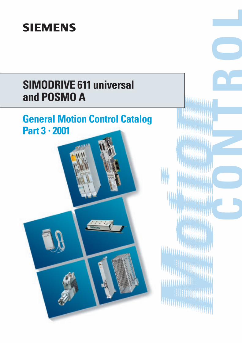
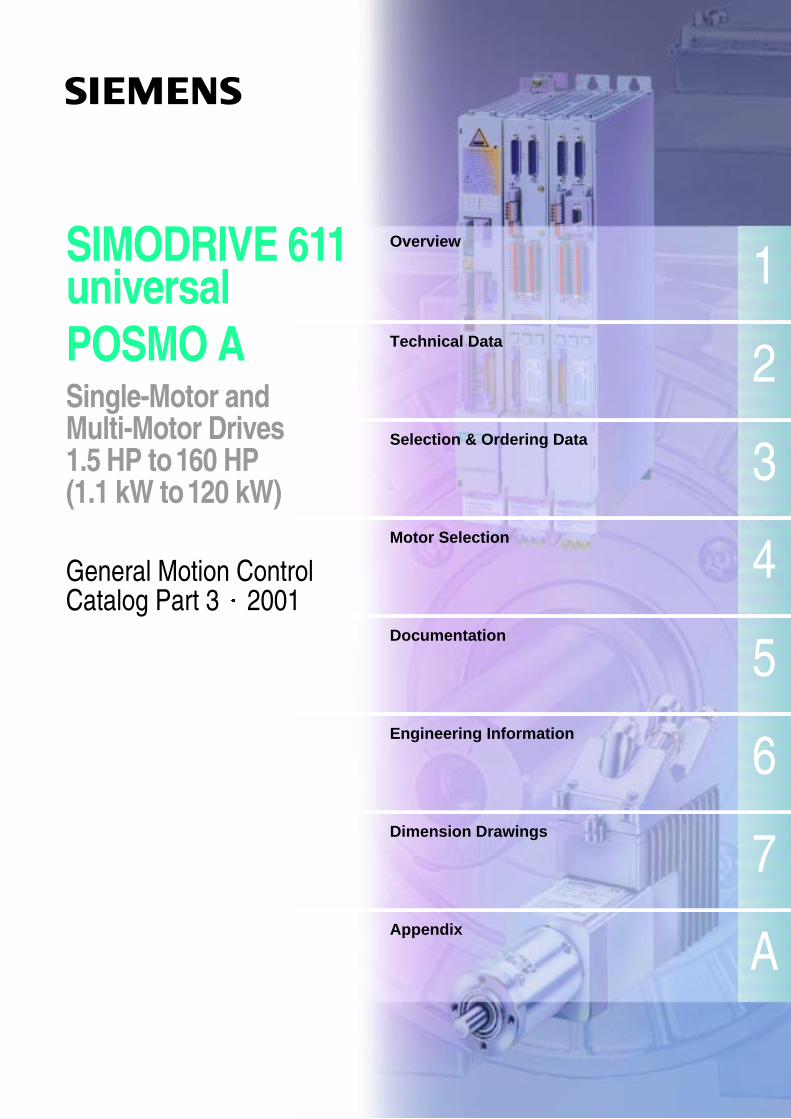
SIMODRIVE 611 universaland POSMO A
General Motion Control CatalogPart 3 • 2001
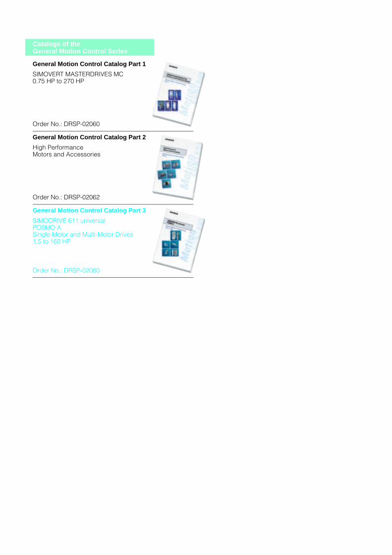
Catalogs of the General Motion Control Series
General Motion Control Catalog Part 1
SIMOVERT MASTERDRIVES MC0.75 HP to 270 HP
Order No.: DRSP-02060
General Motion Control Catalog Part 2
High PerformanceMotors and Accessories
Order No.: DRSP-02062
General Motion Control Catalog Part 3
SIMODRIVE 611 universalPOSMO ASingle-Motor and Multi-Motor Drives1.5 to 160 HP
Order No.: DRSP-02080
2
1
3
4
5
6
7
s
SIMODRIVE 611universalPOSMO ASingle-Motor andMulti-Motor Drives1.5 HP to 160 HP(1.1 kW to 120 kW)
General Motion Control Catalog Part 3 × 2001
A
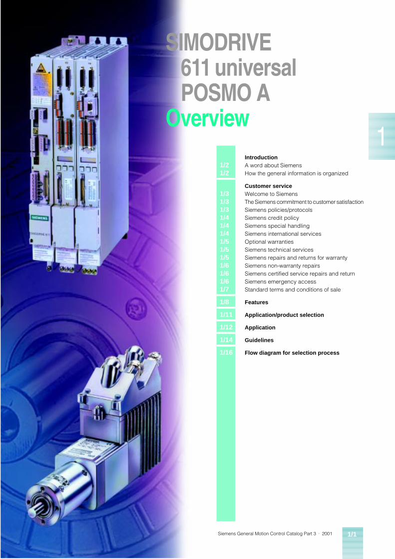
Overview
Technical Data
Selection & Ordering Data
Motor Selection
Documentation
Engineering Information
Dimension Drawings
Appendix

• The technical data, selection and ordering data (order numbers), accessories and availability are subject to alteration.
Warning!
The technical data are intended for general information.Please observe the operating instructions and the references indicated on the products for installation, operation and maintenance.
Trademarks TM
MICROMASTER, COMBIMASTER, SIMATIC, SIMATIC HMI, SIMODRIVE, SIMOLINK, SIMOREG, SIMOVERT, SITOP and STEP are Siemens registered trademarks.All other products and system names in this catalog are (registered) trademarks of their respective owners and must be treated accordingly.
• All dimensions in this catalog are stated in inches (mm).
© Siemens E&A 2000
Siemens General Motion Control Catalog Part 3 · 2001 1/1
1
SIMODRIVE611 universalPOSMO A
Overview
1/21/2
IntroductionA word about SiemensHow the general information is organized
1/31/31/31/41/41/41/51/51/51/61/61/61/7
Customer serviceWelcome to SiemensThe Siemens commitment to customer satisfactionSiemens policies/protocolsSiemens credit policySiemens special handlingSiemens international servicesOptional warrantiesSiemens technical servicesSiemens repairs and returns for warrantySiemens non-warranty repairsSiemens certified service repairs and returnSiemens emergency accessStandard terms and conditions of sale
1/8 Features
1/11 Application/product selection
1/12 Application
1/14 Guidelines
1/16 Flow diagram for selection process
Siemens General Motion Control Catalog Part 3 · 20011/2
SIMODRIVE™ 611 universal and POSMO™ AOverview
1
SIMODRIVE611 universal
SIMODRIVEPOSMO A
■ A word about Siemens Siemens Energy & Automation, inc.
One of the largest Siemens companies in the U.S. is Sie-mens Energy & Automation, Inc. with over 9,800 employees and annual sales in excess of $1.9 Billion.
Siemens Energy & Automation is headquartered near Atlanta, Georgia and has 28 U.S. manu-facturing facilities. SEA’ s facili-ties throughout the U.S. manufacture, market, and ser-vice a wide variety of electrical and electronic equipment and systems that protect, regulate, control, distribute electric pow-er, convert electric power to me-chanical energy, and automate various manufacturing and industrial processes. SEA produces 85% of its products domestically, and markets them worldwide.
Siemens Energy & Automation products are sold in two general market segments: industrial and construction. Our business units are organized into three primary operating di-visions: Industrial Solutions & Software Division, Distribution Products Division and Industrial Systems & Service.
Industrial Solutions & Soft-ware Division business unit
The Solution Business Unit de-velops, engineers, manufac-tures, markets, and services adjustable speed drive and au-tomation products. Our adjust-able speed drive and automation products are among the finest in the world. Siemens drives have historically offered consistently superior perfor-mance and high quality, due to our commitment to continuous improvement in product tech-nologies and production pro-cesses.
■ How the general information is organized
General information
Welcome to SiemensThe Siemens commitment to customer serviceSiemens policies/ protocolsSiemens credit policySiemens special handlingSiemens international servicesSiemens technical servicesSiemens repairs & returns for warrantySiemens non-warranty repairsSiemens certified service repairs and returnsSiemens emergency accessStandard terms and conditions of sale
Siemens AG
The parent company of Sie-mens Energy & Automation is Siemens AG, headquartered in Munich, Germany. Various Sie-mens divisions provide a broad spectrum of products, sys-tems, and services worldwide. These include: electronic components, medi-cal electronics, power engi-neering, and automation products and systems, as well as public and private telecom-munications networks.
Siemens’ worldwide sales ex-ceed $70 Billion in 1999, rank-ing it among the world’s largest electrical companies. Siemens ranks second in manufactur-ing. Siemens employs approxi-mately 440,000 people in 193 countries, 500 manufacturing facilities in 50 countries on 6 continents. A leading edge company Siemens annually reinvests between 8–1 0% of sales in research and develop-ment activities, ranking in the number one position in this cat-egory, along with companies like Intel.
Siemens U.S.A.
The Siemens family of more than twenty companies, sub-sidiaries, affiliates, and joint ventures in the United States is well established and growing with annual sales in excess of $10.4 Billion. Siemens employs more than 58,000 people in the U.S., in ninety-three domestic manufacturing facilities and more than two-hundred thirty sales and service locations.
Introduction
Siemens General Motion Control Catalog Part 3 · 2001 1/3
SIMODRIVE 611 universal and POSMO AOverview
1
SIMODRIVE611 universal
SIMODRIVEPOSMO A
■ Welcome to Siemens In the following pages, we refer to domestic and international products. The definition of these terms is as follows:
Domestic –Those products which are man-ufactured and/or inventoried in North America.
International –Those products which are not inventoried in North America.
As a standard, we are referring to domestic products and spares. If your product or spare does not fall into the domestic category, please see the page marked Siemens International Services.
■ The Siemens commitment to customer satisfaction
Our customer service objective
Meet our customers’ needs and expectations, and add value to our services through:
1. Prompt, reliable service and information.
2. Availability of key personnel to quickly resolve problems.
3. Effective and efficient utiliza-tion of all resources to build a trusting relationship with our customers.
Our standards of service
1. Process quotations within 24-hours with the exception of blanket, international and custom quotations.
2. Enter sales orders within 24-hours of receipt.
3. Return phone calls within one hour of receipt.
4. Make every effort to expedite an order at a customer’s request.
5. Issue credit memos within ten days of receipt of material.
6. Issue invoices within 48 hours.
■ Siemens policies/protocols Siemens E&A’ s responsibility does not extend to any item of the goods which has not been manufactured and sold by Sie-mens E&A. Such item shall be covered only by the express Warranty, if any, of the manufac-turer thereof.
Siemens E&A and its suppliers shall also have no responsibility if the goods have been improp-erly stored, handled or installed, if the goods have not been op-erated or maintained according to their ratings or according to instructions in Siemens E&A or supplier furnished manuals, or if unauthorized repairs or modifi-cations have been made to the goods.
THIS WARRANTY IS EXPRESS-LY IN LIEU OF ALL OTHER WARRANTIES (EXCEPT TITLE, INCLUDING BUT NOT LIMITED TO IMPLIED WARRANTIES OF MERCHANTABILITY AND FIT-NESS, AND CONSTITUTES THE ONLY WARRANTY OF SIE-MENS E&A WITH RESPECT TO THE GOODS.).
The foregoing states Purchas-er’s exclusive remedy against Siemens E&A and the supplier for any defect in the goods or for failure of the goods to be as warranted, whether Purchaser’s remedy is based on contract, warranty, failure of such remedy to achieve its essential purpose, tort (including negligence), strict liability, indemnity, or any other legal theory, and whether arising out of warranties, repre-sentations, instructions, installa-tions or defects from any cause.
If you are a new Siemens Drive Products customer, we thank you for doing business with us. We will work hard to earn your trust and serve your company as if it were our own! If you are currently doing business with us, we thank you for the oppor-tunity to grow with you.
Based on the principle, “One Call Does It All,” we have brought several functions into one operating group. Custom-er Service Representatives have regional assignments and work closely with local area sales offices, application engi-neering, engineering, and our technical service group. We believe this will optimize your satisfaction.
It only requires one phone call to access any of the following:
Order entrySchedulingSpare partsExpeditingRepair programWarranty administrationInvoicing/billingContract administrationReturn goods administra-tionInstruction booksDrawings/drawing trans-mittalsEmergency serviceClaims, disputes, settle-mentsTechnical support
Our overriding concern is your satisfaction. This information has been put together to com-municate our policies and pro-cedures as they pertain to our doing business together. If you have any questions or if you wish to discuss any of the items explained in the following pag-es, please contact your local sales office or the Drive Prod-ucts Customer Service Center.
Standard Siemens Energy & Automation warranty
Siemens E&A warrants that on the date of shipment to the Pur-chaser the goods will be of the kind and quality described in the initial contract, merchant-able, and free of defects in workmanship and material.
If within 12 months from date of initial operation, but not more than 18 months from date of shipment by Siemens E&A, of any item of the goods, Purchas-er discovers that such item was not as warranted above and promptly notifies Siemens E&A in writing thereof, Siemens E&A shall remedy such defect by, at Siemens E&A option, adjust-ment, repair or replacement of the item and any affected part of the goods. Purchaser shall as-sume all responsibility and ex-pense for removal, reinstallation and freight in connection with the foregoing remedy. The same obligations and condi-tions shall extend to replace-ment items furnished by Siemens E&A thereunder. Sie-mens E&A shall have the right of disposal of items replaced by it. Purchaser shall grant Siemens E&A access to the goods at all reasonable times in order for Si-emens E&A to determine any defect in the goods. In the event that adjustment, repair or replacement does not remedy the defect, Siemens E&A and Purchaser shall negotiate in good faith an equitable adjust-ment in the contract price.
Customer service
Siemens General Motion Control Catalog Part 3 · 20011/4
SIMODRIVE 611 universal and POSMO AOverview
1
SIMODRIVE611 universal
SIMODRIVEPOSMO A
Replacement warranty
Should a remanufactured re-placement of a defective item be the solution to a warranty claim, the remanufactured part shall be under warranty for the duration of the warranty of the original item or ninety (90) days, whichever is longer.
A remanufactured part (other than original warranty replace-ment) carries a ninety (90) day warranty.
■ Siemens credit policy
Our terms of payment are Net 30 Days. Invoices are normally sent within 48 hours of ship-ment of goods.
Credit Memos are processed within three days if there is no dispute of charges. If an in-voice is in dispute, our Credit Managers and Customer Ser-vice Representatives will work closely with you to resolve the dispute as quickly as possible.
Should any questions or con-cerns arise regarding your ac-count status, please feel free to contact your local Sales Repre-sentative.
■ Siemens special handling
Freight
All of our original product ship-ments are F.O.B. point of ship-ment; freight charges are prepaid and add. All spare parts are shipped freight pre-paid and add. For freight charges on International prod-ucts and parts, please refer to the index for the listing of Sie-mens International Services.
Orders for customers that re-quire specific freight carriers or copies of freight bills, will be shipped freight collect or third party bill. Freight collect orders are contingent upon freight carrier‘s acceptance of ac-count‘s credit.
Customer account number is required for third party billing.
Customers that request proof of delivery and it is proven that the product was received by the customer, will be charged a $50 net fee for each shipment traced.
Emergency/expedite fees
We have several special pro-grams in order to meet your needs. It is of course necessary to assess a special fee for these services if the product is not un-der warranty. These fees are as follows:
NEXT FLIGHT OUT –Same day delivery for $300. With this service we can receive the order, ship the product and have it delivered in most cases the same day.
NEXT DAY DELIVERY –$200 if the order is received af-ter 4:00 PM Eastern Standard Time.
CUSTOMER PICK UP –There is a two (2) hour process-ing time. All customer pick ups will be ready 2 hours after order is received, and must be picked up within 24 hours.
In addition to the special hand-ling fees above, the purchaser is responsible for any freight charges associated with these shipments if the item being shipped is not under warranty.
Restocking charges
1. Restocking charges apply if you:
a) Have overstocked and wish to return goods.
b)Ordered the wrong part.
c) Initiate a job change.
2. The following charge is now in effect: 10 % for restock of unopened products. 15 % additional charge for repack-aging on opened products.
3. If the part has been dam-aged, a repair cost will be assessed in addition to the above restocking charge.
Minimum order
Drive Products has a minimum order policy of $100 for all do-mestic products and spare part orders. If the order does not to-tal $100 net, an additional fee will be added to bring the total to $100; international orders have a minimum order of $300.
■ Siemens international services
Siemens Energy & Automation supports all Siemens Drive Products in the USA, regardless of their country of origin or mod-el type. Certain specialty prod-ucts are subject to additional logistic requirements. Models in this category are subject to the following special policies.
Freight, duty and taxes
The price for international prod-ucts and spare parts includes freight, duty and taxes.
Special fees
The minimum order for interna-tional items is $250 net. If the or-der does not total $250, an additional charge will be added to bring the total order to $250.
Siemens features an interna-tional emergency warehouse that can ship many parts within 48 hours. Most products and parts can arrive in the United States within 3–5 days, barring any complications with Cus-toms. Your customer service representative can check to see if your part is in stock in the emergency warehouse. If you order from this warehouse there is a $250 emergency fee. Freight, duty and taxes are still included in the price of the part or parts.
International repairs
Contact your local Siemens sales office for price & delivery.
International warranty
Warranty for international prod-ucts, spare parts and repairs are covered under the same policy as our domestic prod-ucts.
Customer service
Siemens General Motion Control Catalog Part 3 · 2001 1/5
SIMODRIVE 611 universal and POSMO AOverview
1
SIMODRIVE611 universal
SIMODRIVEPOSMO A
■ Optional warranties offered with a surcharge of 5% of the net price of the product. This extended warranty offer is only available if ordered prior to time of original shipment from Siemens.
■ Siemens technical services
The Technical Service Group is responsible for technical ser-vice support for customers, field service, and sales engineers. Requests for parts, equipment commissioning, emergency service, or routine maintenance are coordinated and scheduled through this group.
Service coordination and tech-nical support for a wide variety of drive products, including both domestic and international supplied units, are available from this team. Interfacing with the Siemens Service Organiza-tion, other Siemens Divisions, and supplier service facilities, this group is the single point of contact in effectively providing remote technical and field ser-vice support.
Over the past year, an internal survey showed that greater than 95% of the problems called in were resolved over the tele-phone. This level of technical expertise has significantly re-duced the number of on-site service calls.
Technical Service is available 24-hours, 7 days a week by dial-ing 800-241-4453; ask for Drives Technical Services and the call will be channeled auto-matically through a call center which activates the appropriate personnel for both parts and technical support.
■ Siemens repairs & returns for warranty
It would be wonderful if no board ever failed or every ship-ment was perfect. However, there are times when you must return a part for repair or re-placement. Following, please find the steps you need to take in order to return a defective part to Siemens Energy & Auto-mation.
Please make sure to follow these instructions. Parts sent back to Siemens E&A not using the procedures outlined below may cause your warranty to be voided or improper credit to be issued.
Defective part
1. Call – 800-241-4453 and ask for Drives Technical Service, or you may wish to send a fax with the following information to 770-740-3396.
a) Company Name
b)Part Number(s) of item(s) you wish to return
c) Serial Number and Model Number
d)Original P.O. Number or Siemens E&A Sales Order Number, Reason for Return (failure symptom if appli-cable).
2. If you have an emergency, e.g. your equipment is down, and the warranty can be vali-dated commercially, i.e., the shipping or installation date falls within the warranty peri-od, we will ship a replace-ment part to you next day air or next flight out at no charge conditional on a technical val-idation of the warranty once the defective item is received in our repair department. Please note, however, that a conditional 30-day purchase order for warranty replace-ment is required prior to ship-ment of any part. Should you fail to return the defective part within thirty (30) days upon in-structions from your Sales or Customer Service Represen-tative, you will be invoiced in full for the replacement part.
Extended warranty
Drive Products offers an ex-tended warranty for all pro-ducts sold. The extended war-ranty of 12 months is
Deferred warranty
Siemens also offers a Deferred Warranty for all products sold. Commissioning must also be purchased to inspect the con-dition of the drive and super-vise the drive start up. This deferred warranty offer is only available if ordered prior to time of original shipment from Siemens.
The deferred warranty is offered for those applications that will have a delayed installation peri-od, but only require 12 months from the date of commissioning. The chart below is a listing of the warranty periods and fees for the deferred warranty and the extended warranty pro-grams.
Months from Standardwarranty
Extendedwarranty
installation 12 24
manufacturing 18 30
% of net 0% 5%
Months from Standardwarranty
6 monthdeferredwarranty
12 monthdeferredwarranty
installation 12 12 12
manufacturing 18 24 30
% of net 0% 1% 2%
Customer service
Siemens General Motion Control Catalog Part 3 · 20011/6
SIMODRIVE 611 universal and POSMO AOverview
1
SIMODRIVE611 universal
SIMODRIVEPOSMO A
3. If you are not in an emergen-cy situation, once we have received and inspected the defective part and validated the technical warranty, we will repair and return your original product to you at no charge. If the item is unre-pairable we will immediately send a replacement at no charge.
4. An RGA (Return Goods Authorization) will be issued to you on the same day you call. Our RGA form has detailed instructions for the proper return of the part to Siemens. You are responsi-ble for freight charges asso-ciated with any returned part or parts. Please use anti-static bags when shipping printed circuit boards back to Siemens. If you do not have anti-static bags please let RGA Central know at the time of your initial call and they will provide one. If the boards are received back and they do not have the proper protection from stat-ic, the warranty is null and void. Any item received with-out an RGA number will be returned to sender.
5. Our remanufactured parts carry a full ninety (90) day warranty or the remaining period of your original war-ranty, whichever is longer.
Wrong part ordered, shipped, overstock, etc.
If you have ordered the wrong part, find yourself overstocked, or a wrong part has been shipped to you in error, please follow these procedures:
1. Same as #1 above under Defective Part.
2. An RGA (Return Goods Au-thorization) number will be issued to you on the same day you call. Our fax form has detailed instructions on how to ship the part back to us. You are responsible for all freight charges associat-ed with any returned parts.
3. Parts should be returned in their original packaging. However, if you have opened the package, please make sure that the parts to be returned are in an anti-static bag, i.e. all boards. (If the board is returned without this protection, the warranty is null and void).
4. Restocking charges – please refer to the restocking charg-es under Special Handling Charges. Restocking charges will apply only if the return is not Siemens responsibility, i.e., wrong part ordered, over-stock, exchange, etc. If the part has been damaged, a repair cost will be assessed in addition to the restocking charge.
Please note that according to our standard terms and condi-tions, all claims for incorrect items shipped must be made within thirty (30) days after receipt of shipment.
■ Siemens non-warranty repairs
If you have a repair that is non-warranty, please contact your local distributor or simply call 800-241-4453.
Siemens will fax an RGA form with instructions on how to send the item in for repair and return.
■ Siemens certified service repairs and returns
If your warranty has expired, you may still want to take advan-tage of our excellent repair and return program. Highly trained technicians perform incoming tests to determine the exact fail-ure, repair the equipment, and fully test prior to shipment back to you.
However, if you elect, in some instances, we may be able to send you a remanufactured part for 60% of the list price of a new part less your applicable dis-count on an exchange basis. Remanufactured parts carry a ninety (90) day warranty. Your sales or customer service repre-sentative can tell you which parts are included in our repair/return program.
Should you take advantage of this program, please note that if you fail to return the original part to us within ten (10) days, you will be invoiced for the balance of a new board, which is 40%.
Of course, you can always pur-chase a new part at your option!
If you have an emergency and you are down, we have two ex-cellent emergency programs.
(Please note – expedite fees do not apply to parts under warran-ty):
1. NEXT FLIGHT OUT –Most of our products and spare parts can be shipped from our Emergency Depot located at Atlanta Hartsfield International Airport. These parts go next flight out and for most areas of the country are received the same day. There is a $300 expedite charge for this service plus any freight charges associated with the shipment.
2. NEXT DAY AIR –You will receive your part the following day, depending on the location of the ship-to ad-dress. There is a $200 expe-dite charge for this service plus any freight charges as-sociated with the order, if the order is received at our office after 4:00 PM Eastern Stan-dard Time.
■ Siemens emergency access
The Drive Products Business Unit has an emergency spare parts depot at Atlanta Hartsfield International Airport. Same day delivery requirements are often serviced out of this Depot as well as after hour shipments including weekends and holi-days. This has allowed us to ex-pedite emergency shipment, saving several hours in the process.
To activate our Emergency/After Hours Service, simply dial 800-241-4453 and ask for Drives Technical Service and the call will be automatically transferred to our message ser-vice, who will in turn page the On-Call Representative.
Tell the operator there is an emergency and you would like to contact after hour’s personnel for spare parts or technical service, and we will return your call immediately.
Technical assistance
When the Technical Service De-partment, which is responsible for technical support, is unavail-able, a reliable answering ser-vice ensures that a technical service request is relayed im-mediately to one of our engi-neers on call. Should you need technical assistance (other than ordering a part) please call 1-800-241-4453; this toll free number provides day and night access to our Corporate Field Service Organization.
Customer service
Siemens General Motion Control Catalog Part 3 · 2001 1/7
SIMODRIVE 611 universal and POSMO AOverview
1
SIMODRIVE611 universal
SIMODRIVEPOSMO A
■ Standard terms and conditions of sale (1/1/2000)Siemens Energy & Automation, Inc. ("Seller")
1. WARRANTY - (a) Seller warrants that on the date of shipment the goods are of the kind and
quality described herein and are free of non-conformities in workmanship and material. This warranty does not apply to goods delivered by Seller but man-ufactured by others.
(b) Buyer’s exclusive remedy for a nonconformity in any item of the goods shall be the repair or the replacement (at Seller’s option) of the item and any affect-ed part of the goods. Seller’s obligation to repair or replace shall be in effect for a period of one (1) year from initial operation of the goods but not more than eighteen (18) months from Seller’s shipment of the goods, provided Buy-er has sent written notice within that period of time to Seller that the goods do not conform to the above warranty. Repaired and replacement parts shall be warranted for the remainder of the original period of notification set forth above, but in no event less than 12 months from repair or replacement. At its expense, Buyer shall remove and ship to Seller any such nonconforming items and shall reinstall the repaired or replaced parts. Buyer shall grant Sell-er access to the goods at all reasonable times in order for Seller to determine any nonconformity in the goods. Seller shall have the right of disposal of items replaced by it. If Seller is unable or unwilling to repair or replace, or if repair or replacement does not remedy the nonconformity, Seller and Buyer shall negotiate an equitable adjustment in the contract price, which may include a full refund of the contract price for the nonconforming goods.
(c) SELLER HEREBY DISCLAIMS ALL OTHER WARRANTIES, EXPRESS OR IM-PLIED, EXCEPT THAT OF TITLE. SPECIFICALLY, IT DISCLAIMS THE IM-PLIED WARRANTIES OF MERCHANTABILITY, FITNESS FOR A PARTICULAR PURPOSE, COURSE OF DEALING AND USAGE OF TRADE.
(d) Buyer and successors of Buyer are limited to the remedies specified in this article and shall have no others for a nonconformity in the goods. Buyer agrees that these remedies provide Buyer and its successors with a minimum adequate remedy and are their exclusive remedies, whether Buyer’s or its successors’ remedies are based on contract, warranty, tort (including negli-gence), strict liability, indemnity, or any other legal theory, and whether aris-ing out of warranties, representations, instructions, installations, or non-conformities from any cause.
(e) Note: This article 1 does not apply to any software which may be furnished by Seller. In such cases, the attached Software License Addendum applies.
2. PATENTS - Seller shall pay costs and damages finally awarded in any suit against Buyer or its vendees to the extent based upon a finding that the design or construction of the goods as furnished infringes a United States patent (except infringement occurring as a result of incorporating a design or modification at Buyer’s request), provided that Buyer promptly notifies Seller of any charge of in-fringement, and Seller is given the right at its expense to settle such charge and to defend or control the defense of any suit based upon such charge. Seller shall have no obligation hereunder with respect to claims, suits or proceedings, result-ing from or related to, in whole or in part, (i) the use of software or software doc-umentation, (ii) compliance with Buyer’s specifications, (iii) the combination with, or modification of, the goods after delivery by Seller, or (iv) the use of the goods, or any part thereof, in the practice of a process. THIS ARTICLE SETS FORTH SELLER’S ENTIRE LIABILITY WITH RESPECT TO PATENTS.
3. PERFORMANCE; DELAYS - Timely performance by Seller is contingent upon Buyer’s supplying to Seller, when needed, all required technical information and data, including drawing approvals, and all required commercial documentation. If Seller suffers delay in performance due to any cause beyond its reasonable control, the time of performance shall be extended a period of time equal to the period of the delay and its consequences. Seller will give to Buyer notice within a reasonable time after Seller becomes aware of any such delay.
4. SHIPMENT, TITLE AND RISK OF LOSS - (a) The term "shipment" means delivery to the initial carrier in accordance with the
delivery terms of this contract. Seller may make partial shipments. Seller shall select method of transportation and route, unless terms are f.o.b point of ship-ment and Buyer specifies the method and route and is to pay the freight costs in addition to the price. When terms are f.o.b. destination or freight allowed to destination, "destination" means common carrier delivery point (within the United States, excluding Alaska and Hawaii) nearest the destination.
(b) Title to the goods and risk of loss or damage shall pass to Buyer at the f.o.b. point. Seller shall not be responsible for damage to the goods after having re-ceived "in good order" receipts from the carrier.
5. TAXES - Any applicable duties or sales, use, excise, value-added or similar tax-es will be added to the price and invoiced separately (unless an acceptable ex-emption certificate is furnished).
6. TERMS OF PAYMENT - (a) Unless otherwise stated, all payments shall be in United States dollars, and a
pro rata payment shall become due as each shipment is made. If shipment is delayed by Buyer, date of notice of readiness for shipment shall be deemed to be date of shipment for payment purposes.
(b) On late payments, the contract price shall, without prejudice to Seller’s right to immediate payment, be increased by 1 1/2% per month on the unpaid bal-ance, but not to exceed the maximum permitted by law.
(c) If any time in Seller’s judgment Buyer is unable or unwilling to meet the terms specified, Seller may require satisfactory assurance or full or partial payment as a condition to commencing or continuing manufacture or making ship-ment, and may, if shipment has been made, recover the goods from the car-rier, pending receipt of such assurances.
7. NONCANCELLATION - Buyer may not cancel or terminate for convenience, or direct suspension of manufacture, except with Seller’s written consent and then only upon terms that will compensate Seller for its engineering, fabrication and purchasing charges and any other costs relating to such cancellation, termina-tion or suspension, plus a reasonable amount for profit.
8. NUCLEAR - Buyer represents and warrants that the goods covered by this con-tract shall not be used in or in connection with a nuclear facility or application. If Buyer is unable to make such representation and warranty, then Buyer agrees to indemnify and hold harmless Seller and to waive and require its insurers to waive all right of recovery against Seller for any damage, loss, destruction, injury or death resulting from a "nuclear incident", as that term is defined in the Atomic En-ergy Act of 1954, as amended, whether or not due to Seller’s negligence.
9. LIMITATION OF LIABILITY - Neither Seller, nor its suppliers shall be liable, whether in contract, warranty, failure of a remedy to achieve its intended or es-sential purposes, tort (including negligence), strict liability, indemnity or any oth-er legal theory, for loss of use, revenue or profit, or for costs of capital or of substitute use or performance, or for indirect, special, liquidated, incidental or consequential damages, or for any other loss or cost of a similar type, or for claims by Buyer for damages of Buyer’s customers. Seller’s maximum liability un-der this contract shall be the contract price. Buyer and Seller agree that the ex-clusions and limitations set forth in this article are separate and independent from any remedies which Buyer may have hereunder and shall be given full force and effect whether or not any or all such remedies shall be deemed to have failed of their essential purpose.
10. GOVERNING LAW AND ASSIGNMENT - The laws of the State of Georgia shall govern the validity, interpretation and enforcement of this contract, without re-gard to its conflicts of law principles. The application of the United Nations Con-vention on Contracts for the International Sale of Goods shall be excluded. Assignment may be made only with written consent of both parties; provided, however, Seller may assign to its affiliate without Buyer’s consent.
11. ATTORNEY FEES - Buyer shall be liable to Seller for any attorney fees and costs incurred by Seller in enforcing any of its rights hereunder.
12. DISPUTES - Either party may give the other party written notice of any dispute arising out of or relating to this contract and not resolved in the normal course of business. The parties shall attempt in good faith to resolve such dispute promptly by negotiations between executives who have authority to settle the dispute. If the matter has not been resolved within 60 days of the notice, either party may initiate non-binding mediation of the dispute.
13. STATUTE OF LIMITATIONS - To the extent permitted by applicable law, any lawsuit for breach of contract, including breach of warranty, arising out of the transactions covered by this contract, must be commenced not later than twelve (12) months from the date the cause of action accrued.
14. PRICES - In the event of a price increase or decrease, the price of goods on or-der will be adjusted to reflect such increase or decrease. This does not apply to a shipment held by request of Buyer. Goods already shipped are not subject to price increase or decrease. Orders on a bid or contract basis are not subject to this article. Orders amounting to less than $100.00 net will be invoiced at $100.00 plus transportation charges for goods covered by discount schedules. Seller’s prices include the costs of standard domestic packing only. Any deviation from this standard packing (domestic or export), including U.S. Government sealed packing, will result in extra charges. To determine such extra charges, consult Seller’s sales offices.
15. ADDITIONAL TERMS OF PAYMENT -(a) Invoice payment terms are as shown on latest discount sheets as issued from
time to time. Cash discounts are not applicable to notes or trade acceptan-ces, to prepaid transportation charges when added to Seller’s invoices or to discountable items if there are undisputed past due items on the account. Portions of an invoice in dispute should be deducted and the balance remit-ted with a detailed explanation of the deduction. Cash discounts will only be allowed on that portion of the invoice paid within the normal discount period.
(b) Freight will be allowed to any common-carrier free-delivery point within the United States, excluding Alaska and Hawaii, on shipments exceeding $1,000 net or more providing Seller selects the carrier. On shipments to Alaska and Hawaii, freight will be allowed to dockside at the listed port of debarkation nearest the destination point on shipments of $1,000 net or more. Buyer shall pay all special costs such as cartage, stevedoring and insurance. Special freight allowances are as shown on latest discount sheets as issued from time to time. Cataloged weights are estimated, not guaranteed. Seller assumes no responsibility for tariff classifications on carriers.
16. CHANGES IN LAWS AND REGULATIONS - Seller’s prices and timely perfor-mance are based on all applicable laws, rules, regulations, orders, codes, stan-dards or requirements of governmental authorities effective on the date of Seller’s proposal. Any change to any law, rule, regulation, order, code, standard or requirement which requires any change hereunder shall entitle Seller to an eq-uitable adjustment in the prices and any time of performance.
Customer service
Siemens General Motion Control Catalog Part 3 · 20011/8
SIMODRIVE 611 universal and POSMO AOverview
1
SIMODRIVE611 universal
SIMODRIVEPOSMO A
■ Comparison between SIMOVERT MASTERDRIVES MC, SIMODRIVE 611 universal and SIMODRIVE POSMO A
Feature SIMOVERT™ MASTERDRIVES MC
SIMODRIVE 611 universal
SIMODRIVE POSMO A
AC – AC Yes N/A N/A
DC – AC Yes Yes Yes
Output range 0.75 – 335 HP (0.55 – 250 kW) 1.5 – 163 HP (1.1 – 120 kW) 0.1 HP (75 W)
Voltage ratings 380 – 460 V ± 15 % 400 – 460 V + 6 % – 10 % 24 V DC ± 20 %
Frequency range 50/60 Hz ± 6 % 50/60 Hz ± 5 % N/A
Output frequency capability 0 – 400 Hz 0 – 1400 Hz N/A
Max. output voltage 86 % of input voltage (AC)
64 % of input voltage (DC)
86 % of input voltage (AC) N/A
Ambient temperature rating 104 °F (40 °C) Compact & CHASSIS
113 °F (45 °C) Compact PLUS
With derating up to 122 °F (50 °C)
32 °F to 104 °F (0 °C to 40 °C)
With derating up to 113 °F (45 °C)
32 °F to 113 °F (0 °C to 45 °C)
With derating up to 149 °F (65 °C)
Overload capability 160 % x Rated output current (In) for 30 sCycle time: 300 s
or
300 % x Rated output current (In) for 250 ms on Compact PLUSCycle time: 1 s
200 % x Rated output current (In) for 2.65 sCycle time: 10 s
200 % x Rated torque for 15 s
Cycle time: 60 s
Inverter efficiency 96 – 98 % Compact & CHASSIS
93 – 96 % Compact PLUS
98 % 65 %
Gearboxes N/A N/A Planetary gearbox:– Single stage i = 4.5 and 8– Two stage i = 20.25, 36 and 50– Three stage i = 126.56 and 162
Worm Gear:– Single stage i = 5 and 24
Motors which can be connected
SIEMENS synchronous servo motors e.g. 1FT6; 1FK6
SIEMENS asynchronous servo motors e.g. 1PH
SIEMENS induction motors e.g. 1LA; RGZESDI
Standard inverter rated NEMA induction motor
SIEMENS synchronous servo motors e.g. 1FT6; 1FK6
SIEMENS asynchronous servo motors e.g. 1PH
SIEMENS induction motors e.g. 1LA; RGZESDI
SIEMENS linear motors e.g. 1FN
N/A
Features
Siemens General Motion Control Catalog Part 3 · 2001 1/9
SIMODRIVE 611 universal and POSMO AOverview
1
SIMODRIVE611 universal
SIMODRIVEPOSMO A
■ Comparison between SIMOVERT MASTERDRIVES MC, SIMODRIVE 611 universal and SIMODRIVE POSMO A
Feature SIMOVERT MASTERDRIVES MC
SIMODRIVE 611 universal
SIMODRIVE POSMO A
Type of control
V/Hz
V/Hz w/Slip compensation
V/Hz – Textile mode
Open loop vector
Closed loop speed
Torque control
Standard
N/A
N/A
N/A
Standard
Standard
Standard
N/A
N/A
N/A
Standard
Standard
N/A
N/A
N/A
N/A
Standard
N/A
Digital inputs/outputs 2 dedicated inputs (24 V)
4 configurable input/output
4 inputs
4 outputs
2 configurable input/output
Analog inputs
Resolution
(1) ±10 V
10 – BIT + SIGN
(2) ±10 V
13 – BIT + SIGN
N/A
Analog outputs
Resolution
(1) ±10 V
8 – BIT + SIGN
(2) ±10 V
7 – BIT + SIGN
N/A
Skip frequency No Yes N/A
Band stop filter 1 2 N/A
Fixed frequencies 16 N/A N/A
Fault memory Last 8 occurrences (max. 8 faults per occurrence)
Yes No
Warning alarm Yes Yes Yes
Motor protection I2t protection (PTC/thermistor) I 2t protection (PTC/thermistor) I 2t protection
Automatic tune Motor ID, & current loop Yes Pre-tuned ex-work
Communication types
*Optional communication board required
– USS (standard (2) RS232/485 ports)
– Analog (standard)– *PROFIBUS (up to 12 MB)
– *SIMOLINK (Peer to Peer/synchronization)
– *CAN– *Device net– *CC – link
– standard (2) RS232/485 ports)
– Analog (standard)– *PROFIBUS (up to 12 MB)
N/A
N/AN/AN/A
N/A
N/A– PROFIBUS DP up to 12 MB
N/A
N/AN/AN/A
Carrier frequency 5 – 8 kHz
5 – 6 kHz (with technology option)
2 – 8 kHz
3.2 kHz recommendedfor induction motors
4.0 kHz recommended for synchronous motors
N/A
PID control Yes – full function N/A N/A
Braking capability Optional pulse resistor braking or regenerative (brake chopper integrated in AC – AC Compact PLUS units
Optional pulse resistor braking or regenerative (holding braking management integrated)
Built-in resistor for 6.5 and 13.5 HP (5 and 10 kW) O/I modules
Optional external Power Management Module
Features
Siemens General Motion Control Catalog Part 3 · 20011/10
SIMODRIVE 611 universal and POSMO AOverview
1
SIMODRIVE611 universal
SIMODRIVEPOSMO A
■ Comparison between SIMOVERT MASTERDRIVES MC, SIMODRIVE 611 universal and SIMODRIVE POSMO A
Feature SIMOVERT MASTERDRIVES MC
SIMODRIVE 611 universal
SIMODRIVE POSMO A
“S” Curve acceleration Yes with comfort ramp-function generator (free function block)
Yes Ramp up time setting
Hoist brake interface Standard Standard N/A
Standard keypad 6-button, 4-digit, 7-segment red LED‘s
3-button on compact PLUS unit
3-button, 6-digit, 7-segment
N/A
Optional keypad LCD multi-language text display
BUS master/direct parameter access
Parameter storage
N/A N/A
Firmware upgrade via flash e2prom
Standard Standard N/A
Field-weakening operation range for induction motors
1 : 2 1 : 16 N/A
Position control With technology option Yes Yes
Electronic line shaft via fiberoptic cable
Yes(using SIMOLINK)
N/A N/A
Positioning update time
Current update time
Speed update time
1.6 ms
0.2 ms
0.4 ms
1 ms
31.5 ms
0.25 ms
10 ms
125 ms
1 ms
Agency compliance UL listed, CSA, CE UL listed, CSA, CE UL listed, CE
Application
Examples/guidelines
Electronic line shaft
Web handling w/synchronizationPoint to point positioningCut-to-length applications
Point to point positioning
Search for reference Automatic positioning
Positioning of formats or end stop
Positioning of process variables (e.g. by means of motorized valves)
Features
Siemens General Motion Control Catalog Part 3 · 2001 1/11
SIMODRIVE 611 universal and POSMO AOverview
1
SIMODRIVE611 universal
SIMODRIVEPOSMO A
* Simple positioning with V 1.5 and greater.
■ Selection guideline for Siemens, non-machine tool, motion control solutions
FunctionsGeneral Motion Control
MC* MC+ Technology
SIMODRIVEPOSMO A
SIMODRIVE611 universal
FM 357+ 611 u
• Coordinate transformation
• Circular interpolation 2D/3D
• Linear interpolation 2D/3D
• Linear interpolation 2D
• Print mark registration
• Engage/Disengage
• CAM Profile
• Electronic gear
• Virtual master
• Roll feed (Continuous positioning)
• Automatic mode
• MDI (Point-to-Point positioning)
• Referencing (Homing)
• Linear/rotary axis
• Position regulator
• Speed regulator
• Current regulator
Han
dlin
gA
xis
Coo
rdin
atio
nSy
nchr
oniz
atio
nPo
sitio
ning
Bas
ic fu
nctio
ns
Application/product selection
Siemens General Motion Control Catalog Part 3 · 20011/12
SIMODRIVE 611 universal and POSMO AOverview
1
SIMODRIVE611 universal
SIMODRIVEPOSMO A
■ SIMODRIVE 611 universal
With a proven hardware plat-form in the machine tool indus-try, the new 611 U (U for “Universal”) has been de-signed to handle a range of General Motion Control appli-cations. Capable of controlling various motor types, be it Synchronous Servo, Asynchro-nous Servo, standard Induction or Linear. Its compact multi-axis design is well suited for many industries – i.e. printing, packaging, textile, wood, glass, etc.
The SIMODRIVE 611 universal is supplied for line voltages of 3-phase 380 V to 480 V AC, 50/60 Hz and is available from 1.5 HP to 160 HP (1.1 to 120 kW). The modules have a standard design of 19 inches (480 mm) high by 11.5 inches (288 mm) deep and depending on the power range, the width increases in units of 2 inches (50 mm).
Some of the main features of the SIMODRIVE 611 universal are as follows:
• configurable for speed/torque control and positioning control
• suitable for synchronous and induction motors
• compact design with 1-axis and 2-axis modules
• communication with PROFIBUS
• and all data in the package present on a transferable memory submodule
In addition to classical drive functions such as torque and speed control with output fre-quencies up to 1400 Hz, SIMODRIVE 611 U offers inte-gral positioning functions.
Up to 64 independent travers-ing blocks can be stored to per-form either absolute or relative position moves allowing it to be characterized by
• extremely high dynamic per-formance
• flexible positioning
• high field weakening range
• and ease of use.
The program is rounded off by a complete spectrum of system components and accessories.
Customer specific, integral so-lutions (automation – drives – motors) are available for the most varied of applications in all industrial sectors.
For the SIMODRIVE 611 univer-sal, an easy to use Windows based graphical programming and diagnostic tool is available. Known as SIMOCOM U, this tool has been specially developed to make start up of the drive sys-tem effortless.
Siemens‘ world-wide service and the company‘s sales net-work enable all our customers to obtain direct access to expert advice and project planning as well as training and service.
Customized Solutions
The drives are available inter-nally cooled, externally cooled, or via external hose cooling to fit all cabinet configurations.
Infeed modules are available as unregulated rectifiers up to 13.5 HP (10 kW) utilizing pulsed resistors to dissipate excess energy. Above 13.5 HP (10 kW) regulated regenerative units are utilized to return excess energy to the supply.
Application
Siemens General Motion Control Catalog Part 3 · 2001 1/13
SIMODRIVE 611 universal and POSMO AOverview
1
SIMODRIVE611 universal
SIMODRIVEPOSMO A Application
■ SIMODRIVE POSMO A
To increase productivity in pro-duction, it requires optimization of such factors as throughput, availability and machine price. Positioning plays a significant role.
SIMODRIVE POSMO A (Actuator) is an intelligent posi-tioning motor and is a partici-pant on a PROFIBUS-DP distributed network.
Main features:
• Power section and entire movement control in the motor
• Linking via communication and power bus
• PROFIBUS-DP standard slave
With its well designed distribut-ed concept, SIMODRIVE POSMO A opens up a new level in automation.
Typical applications are the:
• Adjustment of formats or end stops
• Setting of process variables, for example via motorized valves
Improved production costs:
Lower engineering costs can be achieved through the distribut-ed drive architecture. Produc-tion time can be improved due to short set-up times and auto-mated process variable settings through intelligent movement control.
SIMODRIVE POSMO A func-tions well in machines for pack-aging, wood, glass, printing, plastics, and transfer lines. They are also used in medical diag-nostics for moving table tops or X-ray equipment.
Optimal integration of drives into the world of automation
MICRO-MASTER
MASTER-DRIVES VC
PC/PG SIMATIC HMI SIMATIC S7/M7/FM
PROFIBUS-DP/MC
SIMOLINK
SIMODRIVE
MICROMASTER
MASTER-DRIVES MC
GM
C-5
005a
Open Loop Control Closed Loop Control Motion Control CNC drives
SIMOREGDC MASTER
COMBI-MASTER
SIMODRIVE611 universal
POSMO ATMTM
TM
TM
TM
Siemens General Motion Control Catalog Part 3 · 20011/14
SIMODRIVE 611 universal and POSMO AOverview
1
SIMODRIVE611 universal
SIMODRIVEPOSMO A
6MC
-513
g
1-phase AC supply1-phase AC supply 3-phase AC supply3-phase AC supply
unregulated/non-regenerative
regulated/regenerative
1-axis 2-axis
Guidelines
Siemens General Motion Control Catalog Part 3 · 2001 1/15
SIMODRIVE 611 universal and POSMO AOverview
1
SIMODRIVE611 universal
SIMODRIVEPOSMO A
Technical data
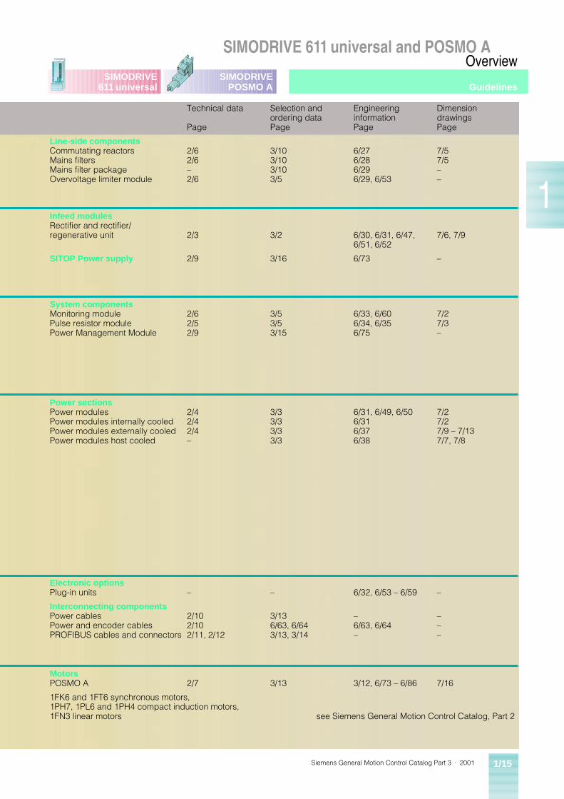
Page
Selection andordering dataPage
Engineering informationPage
DimensiondrawingsPage
Line-side componentsCommutating reactorsMains filtersMains filter packageOvervoltage limiter module
2/62/6–2/6
3/103/103/103/5
6/276/286/296/29, 6/53
7/57/5––
Infeed modulesRectifier and rectifier/regenerative unit 2/3 3/2 6/30, 6/31, 6/47,
6/51, 6/527/6, 7/9
SITOP Power supply 2/9 3/16 6/73 –
System componentsMonitoring modulePulse resistor modulePower Management Module
2/62/52/9
3/53/53/15
6/33, 6/606/34, 6/356/75
7/27/3–
Power sectionsPower modulesPower modules internally cooledPower modules externally cooledPower modules host cooled
2/42/42/4–
3/33/33/33/3
6/31, 6/49, 6/506/316/376/38
7/27/27/9 – 7/137/7, 7/8
Electronic optionsPlug-in units – – 6/32, 6/53 – 6/59 –
Interconnecting componentsPower cablesPower and encoder cablesPROFIBUS cables and connectors
2/102/102/11, 2/12
3/136/63, 6/643/13, 3/14
–6/63, 6/64–
–––
MotorsPOSMO A 2/7 3/13 3/12, 6/73 – 6/86 7/16
1FK6 and 1FT6 synchronous motors, 1PH7, 1PL6 and 1PH4 compact induction motors, 1FN3 linear motors see Siemens General Motion Control Catalog, Part 2
Guidelines
Siemens General Motion Control Catalog Part 3 · 20011/16
SIMODRIVE 611 universal and POSMO AOverview
1
SIMODRIVE611 universal
SIMODRIVEPOSMO A
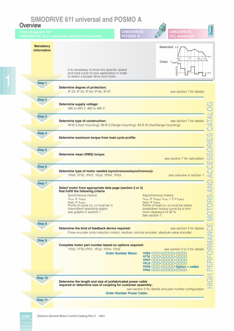
Mandatoryinformation
i-1
t
Tt
t it1t
DA
65-5
775
n
rated
Speed [rpm]
Torque
A
Step 1
Step 2
Step 3
Step 4
Step 5
Step 6
Step 7
Step 8
It is necessary to know the specific speedand load cycle of your application in orderto select a proper drive and motor.
Determine degree of protection:IP 23; IP 55; IP 64; IP 65; IP 67 see section 7 for details
Determine supply voltage:380 to 400 V; 460 to 480 V
Determine type of construction: see section 7 for detailsIM B 3 (foot mounting); IM B 5 (flange mounting); IM B 35 (foot/flange mounting)
Determine maximum torque from load cycle profile:
Determine mean (RMS) torque:see section 7 for calculation
Determine type of motor needed (synchronous/asynchronous):1FK6; 1FT6; 1PH7; 1PL6; 1PH4; 1FN3 see overview in section 1
Select motor from appropriate data page (section 2 or 3)that fulfill the following criteria
Synchronous motors: Asynchronous motors:nmax £ nrated nmax £ nrated; tmax < 2 x tratedtRMS £ trated tRMS £ tratedPoints of cycle (ni, ti) must be in Points of load (ni, ti) must be belowintermittent operating region breakdown torque curve by a mini-see graphs in section 7. mum clearance of 30 %.
See section 7.
Determine the kind of feedback device required: see section 4 for detailsPulse encoder (only induction motor); resolver; sin/cos encoder; absolute value encoder
Step 9Complete motor part number based on options required:
1FK6; 1FT6;1PH7; 1PL6; 1PH4; 1FN3 see section 2 or 3 for detailsOrder Number Motor: 1FK6 ¨¨¨-¨¨¨¨¨-¨¨¨¨
1FT6 ¨¨¨-¨¨¨¨¨-¨¨¨¨1PH7 ¨¨¨-¨¨¨¨¨-¨¨¨¨1PL6 ¨¨¨-¨¨¨¨¨-¨¨¨¨1PH4 ¨¨¨-¨¨¨¨¨-Option + codes1FN3 ¨¨¨-¨¨¨¨¨-¨¨¨¨
Step 10Determine the length and size of prefabricated power cablerequired or determine size of coupling for customer assembly:
see section 5 for details and part number configurationOrder Number Power Cable:
Step 11
HIG
H PE
RFO
RMAN
CE M
OTO
RS A
ND A
CCES
SORI
ES C
ATAL
OG
Flow diagram for SIMODRIVE 611 universal selection process
Siemens General Motion Control Catalog Part 3 · 2001 1/17
SIMODRIVE 611 universal and POSMO AOverview
1
SIMODRIVE611 universal
SIMODRIVEPOSMO A
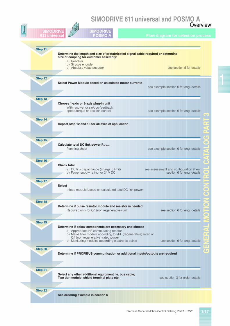
Step 11Determine the length and size of prefabricated signal cable required or determinesize of coupling for customer assembly:
a) Resolverb) Sin/cos encoderc) Absolute value encoder see section 5 for details
GEN
ERAL
MO
TIO
N CO
NTRO
L CA
TALO
G P
ART
3
Step 13Choose 1-axis or 2-axis plug-in unit
With resolver or sin/cos-feedbackspeed/torque or position control see example section 6 for eng. details
Step 12Select Power Module based on calculated motor currents
see example section 6 for eng. details
Step 14Repeat step 12 and 13 for all axes of application
Step 15Calculate total DC link power PDClink
Planning sheet see example section 6 for eng. details
Step 16Check total:
a) DC link capacitance (charging limit) see assessment and configuration sheatb) Power supply rating for 24 V DC section 6 for eng. details
Step 17Select
Infeed module based on calculated total DC link power
Step 20Determine if PROFIBUS communication or additional inputs/outputs are required
Step 18Determine if pulse resistor module and resistor is needed
Required only for O/I (non regenerative) unit see section 6 for eng. details
Step 21Select any other additional equipment i.e. bus cable;Two tier module; shield terminal plate etc. see section 3 for order details
Step 22See ordering example in section 6
Step 19Determine if below components are necessary and choose
a) Appropriate HF commutating reactorb) Mains filter module according to I/RF (regenerative) rated or
O/I (non regenerative) rated powerc) Monitoring modules according electronic points see section 6 for eng. details
Flow diagram for selection process

Siemens General Motion Control Catalog Part 3 · 20011/18
SIMODRIVE 611 universal and POSMO AOverview
1
SIMODRIVE611 universal
SIMODRIVEPOSMO ANotes
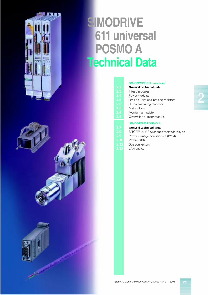
Siemens General Motion Control Catalog Part 3 · 2001 2/1
2
SIMODRIVE611 universalPOSMO A
Technical Data
2/22/32/42/52/62/62/62/6
SIMODRIVE 611 universalGeneral technical data Infeed modulesPower modulesBraking units and braking resistorsHF commutating reactorsMains filtersMonitoring moduleOvervoltage limiter module
2/72/92/92/102/112/12
SIMODRIVE POSMO AGeneral technical data SITOPTM 24 V Power supply standard typePower management module (PMM)Power cableBus connectorsLAN cables
Siemens General Motion Control Catalog Part 3 · 20012/2
SIMODRIVE 611 universalTechnical Data
2
SIMODRIVE611 universal
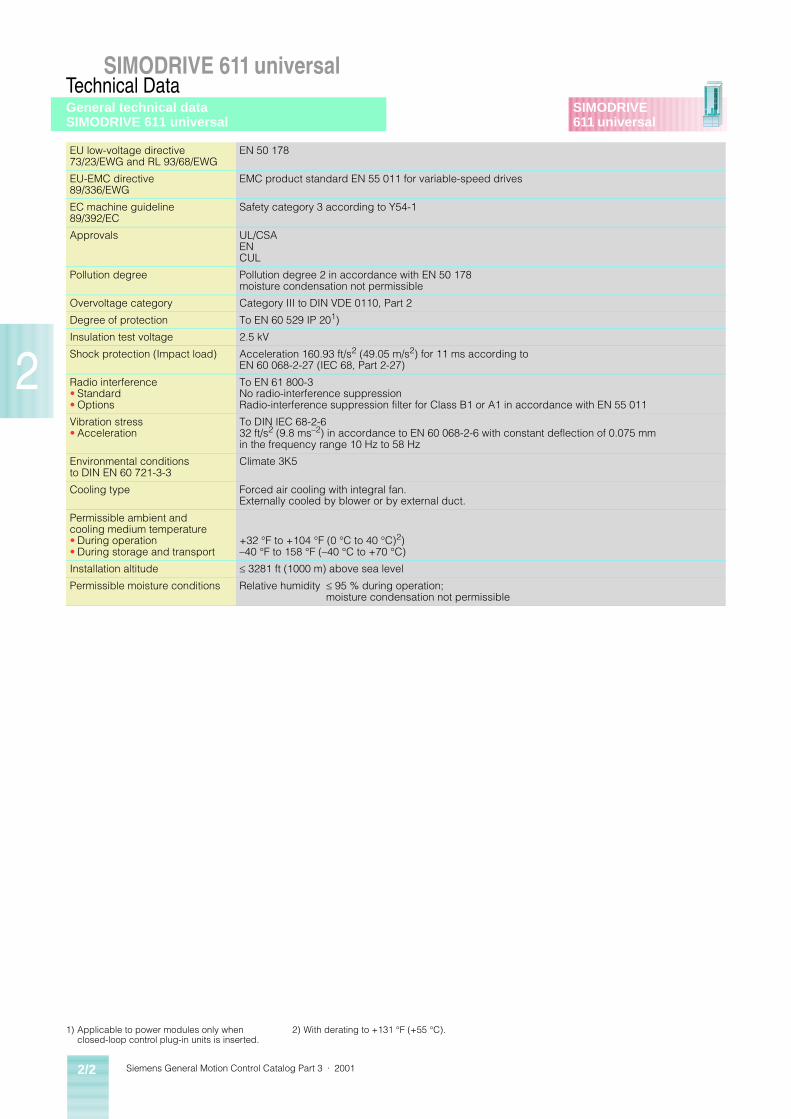
EU low-voltage directive 73/23/EWG and RL 93/68/EWG
EN 50 178
EU-EMC directive 89/336/EWG
EMC product standard EN 55 011 for variable-speed drives
EC machine guideline 89/392/EC
Safety category 3 according to Y54-1
Approvals UL/CSAENCUL
Pollution degree Pollution degree 2 in accordance with EN 50 178 moisture condensation not permissible
Overvoltage category Category III to DIN VDE 0110, Part 2
Degree of protection To EN 60 529 IP 201)
Insulation test voltage 2.5 kV
Shock protection (Impact load) Acceleration 160.93 ft/s2 (49.05 m/s2) for 11 ms according to EN 60 068-2-27 (IEC 68, Part 2-27)
Radio interference• Standard• Options
To EN 61 800-3No radio-interference suppressionRadio-interference suppression filter for Class B1 or A1 in accordance with EN 55 011
Vibration stress• Acceleration
To DIN IEC 68-2-632 ft/s2 (9.8 ms–2) in accordance to EN 60 068-2-6 with constant deflection of 0.075 mm in the frequency range 10 Hz to 58 Hz
Environmental conditions to DIN EN 60 721-3-3
Climate 3K5
Cooling type Forced air cooling with integral fan.Externally cooled by blower or by external duct.
Permissible ambient and cooling medium temperature• During operation• During storage and transport
+32 °F to +104 °F (0 °C to 40 °C)2)–40 °F to 158 °F (–40 °C to +70 °C)
Installation altitude � 3281 ft (1000 m) above sea level
Permissible moisture conditions Relative humidity � 95 % during operation;moisture condensation not permissible
1) Applicable to power modules only when closed-loop control plug-in units is inserted.
2) With derating to +131 °F (+55 °C).
General technical dataSIMODRIVE 611 universal
Siemens General Motion Control Catalog Part 3 · 2001 2/3
SIMODRIVE 611 universalTechnical Data
2
SIMODRIVE611 universal
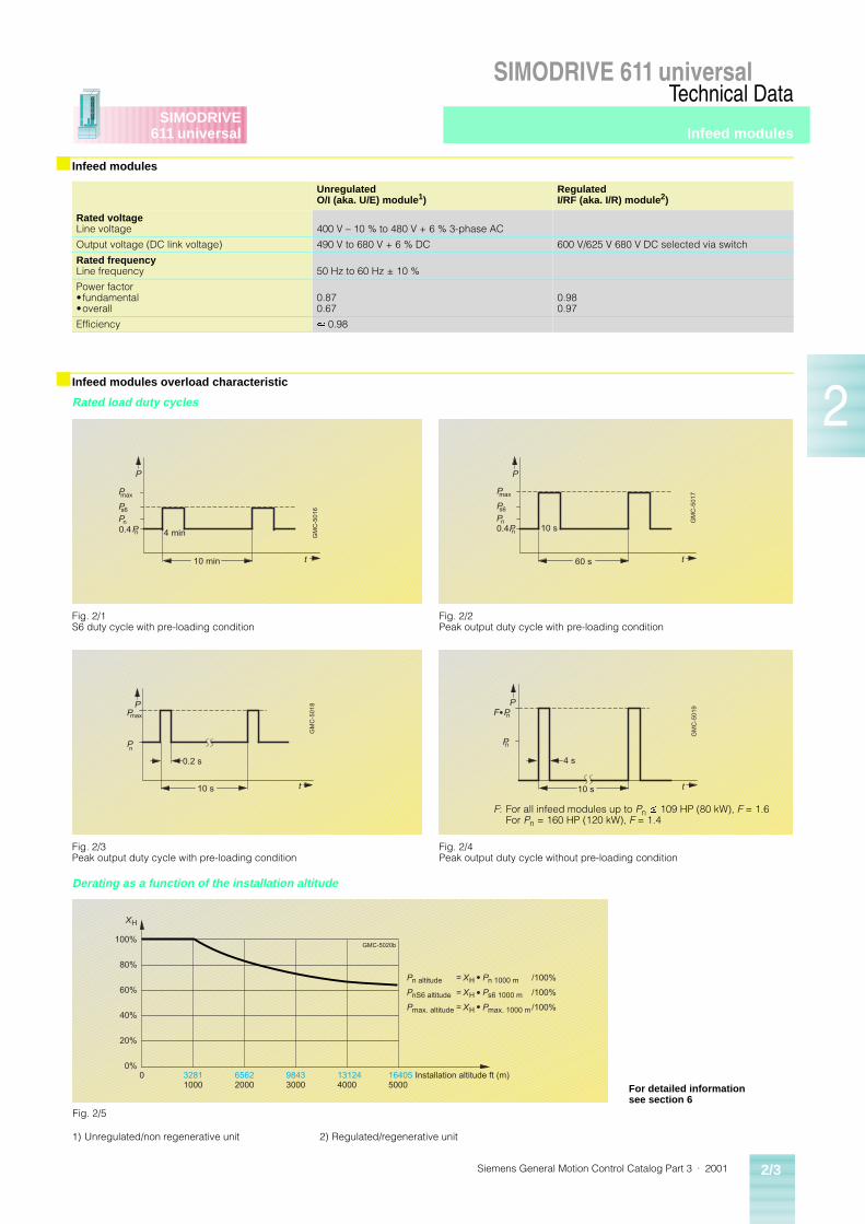
■ Infeed modules
UnregulatedO/I (aka. U/E) module1)
RegulatedI/RF (aka. I/R) module2)
Rated voltageLine voltage 400 V – 10 % to 480 V + 6 % 3-phase AC
Output voltage (DC link voltage) 490 V to 680 V + 6 % DC 600 V/625 V 680 V DC selected via switch
Rated frequencyLine frequency 50 Hz to 60 Hz ± 10 %
Power factor• fundamental•overall
0.870.67
0.980.97
Efficiency » 0.98
■ Infeed modules overload characteristic
Rated load duty cycles
Derating as a function of the installation altitude
1) Unregulated/non regenerative unit 2) Regulated/regenerative unit
GM
C-5
01
6
P
Pmax
t10 min
4 min
Ps6
Pn
Pn0.4
Fig. 2/1S6 duty cycle with pre-loading condition
GM
C-5
01
7
P
Pmax
t60 s
10 s
Ps6
PnPn0.4
Fig. 2/2Peak output duty cycle with pre-loading condition
GM
C-5
01
8
0.2 s
PPmax
Pn
t10 s
Fig. 2/3Peak output duty cycle with pre-loading condition
GM
C-5
01
9
4 s
PF P
Pn
t10 s
n
Fig. 2/4Peak output duty cycle without pre-loading condition
F: For all infeed modules up to Pn £ 109 HP (80 kW), F = 1.6For Pn = 160 HP (120 kW), F = 1.4
32811000
0 65622000
98433000
131244000
164055000
0%
20%
40%
60%
80%
100%
Installation altitude ft (m)
Pn altitude = XH Pn 1000 m /100%
PnS6 altitude = XH Ps6 1000 m /100%
Pmax. altitude = XH Pmax. 1000 m /100%
XH
GMC-5020b
Fig. 2/5
For detailed informationsee section 6
Infeed modules
Siemens General Motion Control Catalog Part 3 · 20012/4
SIMODRIVE 611 universalTechnical Data
2
SIMODRIVE611 universal
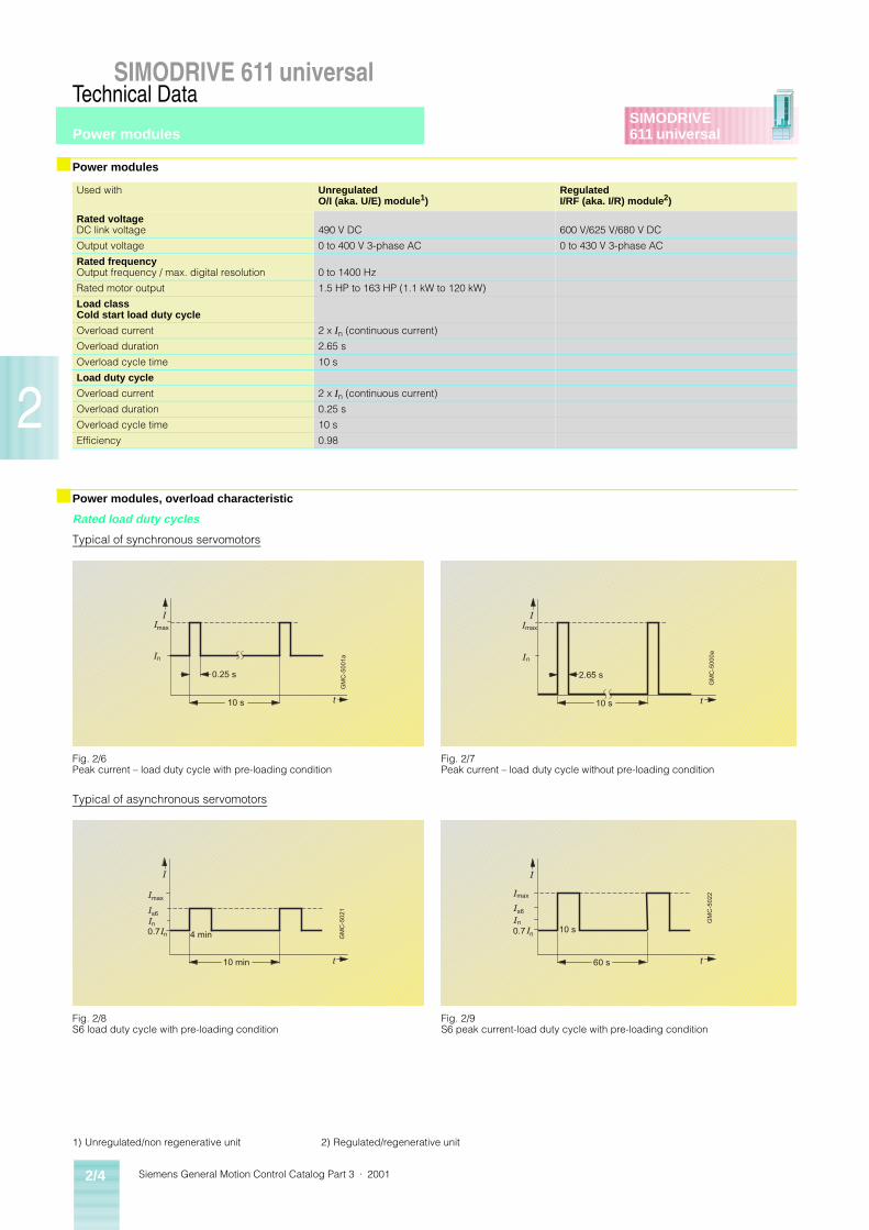
■ Power modules
Used with UnregulatedO/I (aka. U/E) module1)
RegulatedI/RF (aka. I/R) module2)
Rated voltageDC link voltage 490 V DC 600 V/625 V/680 V DC
Output voltage 0 to 400 V 3-phase AC 0 to 430 V 3-phase AC
Rated frequencyOutput frequency / max. digital resolution 0 to 1400 Hz
Rated motor output 1.5 HP to 163 HP (1.1 kW to 120 kW)
Load classCold start load duty cycle
Overload current 2 x In (continuous current)
Overload duration 2.65 s
Overload cycle time 10 s
Load duty cycle
Overload current 2 x In (continuous current)
Overload duration 0.25 s
Overload cycle time 10 s
Efficiency 0.98
■ Power modules, overload characteristic
Rated load duty cycles
Typical of synchronous servomotors
Typical of asynchronous servomotors
1) Unregulated/non regenerative unit 2) Regulated/regenerative unit
GM
C-5
00
1a
0.25 s
IImax
In
t10 s
Fig. 2/6Peak current – load duty cycle with pre-loading condition
GM
C-5
00
0a
2.65 s
IImax
In
t10 s
Fig. 2/7Peak current – load duty cycle without pre-loading condition
GM
C-5
02
1
I
Imax
t10 min
4 min
Is6
In
In0.7
Fig. 2/8S6 load duty cycle with pre-loading condition
GM
C-5
02
2
I
Imax
n
t60 s
10 s
Is6
IIn0.7
Fig. 2/9S6 peak current-load duty cycle with pre-loading condition
Power modules
Siemens General Motion Control Catalog Part 3 · 2001 2/5
SIMODRIVE 611 universalTechnical Data
2
SIMODRIVE611 universal
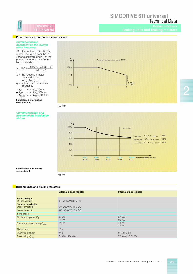
■ Power modules, current reduction curves
Current reduction dependent on the inverter clock frequencyX1 = Current reduction factor, current reduction from the in-verter clock frequency f0 of the power transistors (refer to the technical data).
X = the reduction factor obtained [in %] for In, IS6, Imax.
fT = selected inverter clock frequency
® InfT = X · Inf0/100 %® Is6fT = X · Is6f0/100 %® Imax.fT = X · Imax.f0/100 %
For detailed information see section 6
Current reduction as a function of the installation altitude
For detailed information see section 6
■ Braking units and braking resistors
External pulsed resistor Internal pulse resistor
Rated voltageDC link voltage 600 V/625 V/680 V DC
Service thresholdsUpper threshold 644 V/670 V/744 V DC
Lower threshold 618 V/640 V/718 V DC
Load class
Continuous power PD 0.3 kW1.5 kW
0.3 kW0.2 kW
Short-time power rating Pmax 25 kW 25 kW10 kW
Cycle time 10 s
Overload duration 0.6 s 0.12 s; 0.2 s
Peak rating Emax 7.5 kWs; 180 kWs 7.5 kWs; 13.5 kWs
XX f f
f= ⋅
100100 1
8 0
% –( % – ) ( – )
–T 0
kHz
GM
C-5
02
3
[kHz]
8
100
f0
Ambient temperature up to 40 °CII
0
0 %
%
n
f1
X1
Fig. 2/10
32811000
0 65622000
98433000
131244000
164055000
0%
20%
40%
60%
80%
100%
Installation altitude ft (m)
n altitude = XH n 1000 m /100%
S6 altitude = XH s6 1000 m /100%
max. altitude = XH max. 1000 m /100%
XH
GMC-5134a
I
I
I
I
I
I
Fig. 2/11
Power modulesBraking units and braking resistors
Siemens General Motion Control Catalog Part 3 · 20012/6
SIMODRIVE 611 universalTechnical Data
2
SIMODRIVE611 universal
■ HF commutating reactors, supply voltage 400/480 V 3-phase AC
Supply voltage 400 V 3-phase AC ± 10 % to 480 V 3-phase AC + 6 % – 10 %
Frequency 50/60 Hz ± 10 %
Degree of protection IP 00 in accordance with DIN EN 60 529 (IEC 60 529)
Humidity classification according to DIN EN 60 721-3-3
Cl. 3K5, condensation and icing excluded.Low air temperature: +32 °F (0 °C)
Permissible ambient temperature•Operation•Storage and transport
–13 °F to +104 °F (–25 °C to +40 °C), up to +131 °F (+55 °C) with derating–13 °F to +176 °F (–25 °C to +80 °C)
■ Mains filters
Supply voltage1) 400 V 3-phase AC ± 10 % or 415 V 3-phase AC ± 10 % (TN network)
Frequency 50/60 Hz ± 10 %
Degree of protection IP 20 according to DIN EN 60 529 (IEC 60 529)
Humidity classification according to DIN EN 60 721-3-3
Cl. 3K5, condensation and icing excluded.Low air temperature: +32 °F (0 °C)
Permissible ambient temperature•Operation
•Storage and transport
+32 °F to +104 °F (0 °C to +40 °C), up to +131 °F (+55 °C) with 0.6 x Prated of the O/I or I/RF module–13 °F to +158 °F (–25 °C to +70 °C)
Interference suppression According to EN 55 011, conducted limit class A if configured according to the Planning Guide
■ Monitoring module
Rated supply voltage 400 V 3-phase AC – 10 % to 480 V 3-phase AC + 6 % 50 Hz to 60 Hz ± 10 % or 490 V to 680 V DC
Power loss 70 W
■ Overvoltage limiter module
Maximum energy absorption 100 joule
1) If a mains filter required, direct connection to 480 V 3-phase AC input is not possible. A separate isolation transformer is required. Further, output of the system will be reduced to approx. 350 V A. Take care to select the motor based on this rating.
General technical dataSIMODRIVE POSMO A
Siemens General Motion Control Catalog Part 3 · 2001 2/7
SIMODRIVE POSMO ATechnical Data
2
SIMODRIVEPOSMO A
■ Motor Data
Supply voltage 24 V DC ± 20 %Rated power and voltage are reduced when the power supply voltage drops below 24 V.
Motor type Permanent-magnet brushless servomotor (brushless DC: BLDC)
Degree of Protection(to DIN EN 60 529)
IP 54 (TENV)IP 40 at the motor shaft and planetary gearbox shaft. The shaft may not run in an oil bath. If necessary, grease lubrication must be provided.
Cooling Non-ventilated (free convection)
Overload• S3 15 %, 60 s• Monitoring
2 x rated torque for 15 s within 60 s I2t limit
Position encoder (integrated) IncrementalResolution 816 ppr
Rated motor speed 3000 rpm
Rated motor torque 1.6 lbf-in (0.18 Nm)
Rated motor current 4.5 A
Motor efficiency 65 %
Motor moment of inertia 0.531 x 10⁻³ lb-in-s2 (0.06 x 10⁻³ kgm2)
Permissible ambient temperature(to DIN EN 60 721, Part 3-3 class 3K5)• Operating• Extended operating• Transport and storage
+32 °F to 113 °F (0 °C to 45 °C)+32 °F to 149 °F (0 °C to 65 °C) (with continuous current reduction)–40 °F to 158 °F (–40 °C to 70 °C) (to DIN EN 60 721, Parts 3-1 and 3-2, classes 2K4 and 1K4)
Installation altitude 3300 ft (1000 m) above sea level4900 ft (1500 m) Derating factor 0.916600 ft (2000 m) Derating factor 0.889900 ft (3000 m) Derating factor 0.83
14800 ft (4500 m) Derating factor 0.7519700 ft (6000 m) Derating factor 0.68
Gearbox lifetime A generally valid statement regarding the gearbox lifetime cannot be made due to the diversity of applications possibilities and the resulting load types as well as the extremely wide range of ambient conditions.
Caution!
If the worm gear must be rotated due to the mechanical configuration, the retaining bolts must be subsequently tightened with a torque of 1.5 lbf-ft (2 Nm) and secured using Loctite 274. Warranty is not provided for damage if incorrectly handled.
Vibration stressing in operation(to IEC 68-2-6, DIN EN 60 721,Parts 3-0 and 3-3, class 3M6)
Frequency range 2 … 9 Hz with constant deflection = 0.276 in (7 mm)Frequency range 9 … 200 Hz with constant acceleration = 65.6 ft/s2 (20 m/s2)
Shock stressing in operation(to DIN EN 60 721 Parts 3-0 and 3-3, class 3M8)• Peak acceleration• Shock duration
max. 250 ms2
6 ms
Vibration and shock stressing during transport
To DIN EN 60 721, Part 3-3, class 2M2 (data is valid for components in their original packing)
List of materials • Electronic housing GD-ALSi12 (CU) (die cast aluminum)• Motor bearing end-shields GD-ZNAL4 (zinc die cast)• Motor shaft 100CR6 DIN 17 350• Gearbox end-shield GD-ZNAL4 (zinc die cast)• Gearbox shaft X40CR13 DIN 17 440• Gearbox flange X12CR MO S17 DIN 17 440• Gearbox hollow wheel (housing) 16MN CR5 BKW; galvanized surface
Stressing as a result of cooling and lubrication medium
The stressing of seals was tested using various cooling and lubricating mediums.The result of the tests of compatible mediums can be requested when required.However, incompatibilities cannot be generally excluded due to the continually changing chemical composition for cooling and lubricating mediums.
General technical dataSIMODRIVE POSMO A
Siemens General Motion Control Catalog Part 3 · 20012/8
SIMODRIVE POSMO ATechnical Data
2
SIMODRIVEPOSMO A
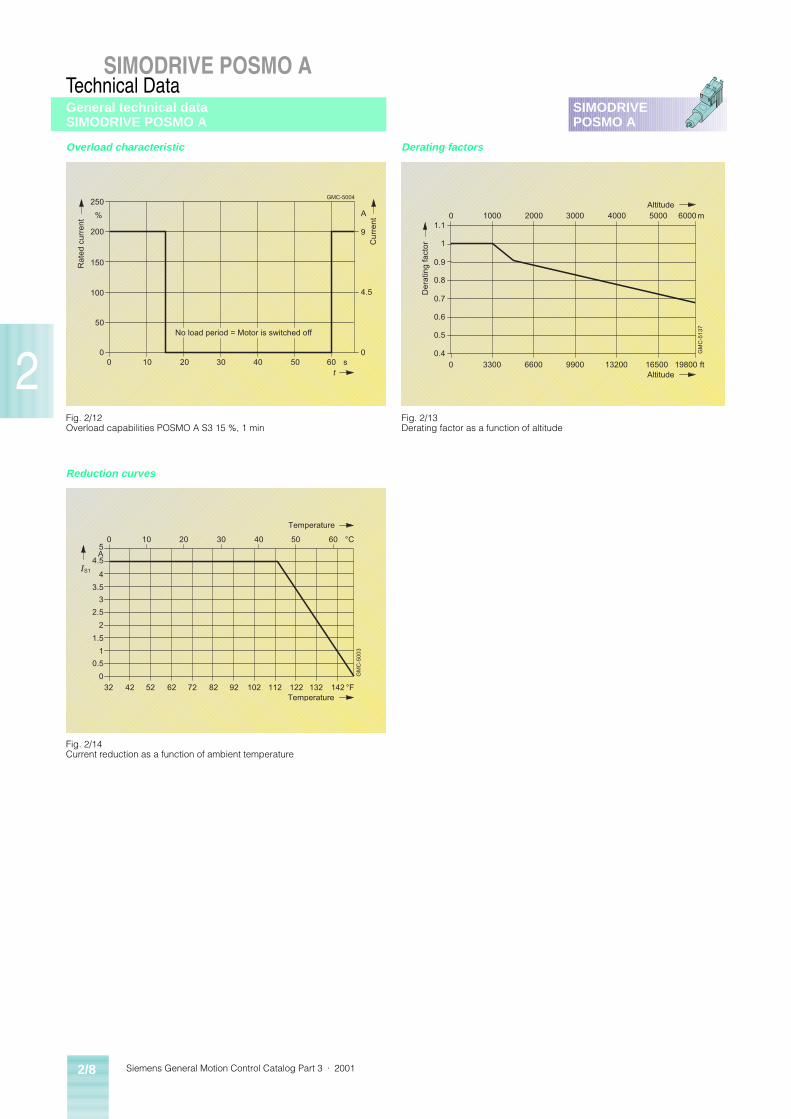
Overload characteristic Derating factors
Reduction curves
0
50
100
200
250
150
%
0 10 20 30 40 50 600
4.5
9
s
A
t
Ra
ted
cu
rre
nt
Cu
rre
nt
No load period = Motor is switched off
GMC-5004
Fig. 2/12Overload capabilities POSMO A S3 15 %, 1 min
Fig. 2/13Derating factor as a function of altitude
0 1000 2000 3000 4000 5000 6000m1.1
1
0.9
0.8
0.6
0.4
0 3300 6600 9900 13200 16500 ftAltitude
GM
C-5
13
7
19800
Dera
ting f
act
or
Altitude
0.7
0.5
0 10 20 30 40 50 60 °C5
4.5
4
3.5
3
2.5
2
1.5
1
0.5
0
32 42 52 62 72 82 92 102 112 122 132 142 °F
A
Temperature
Temperature
IS1
GM
C-5
00
3
Fig. 2/14Current reduction as a function of ambient temperature
General technical dataSIMODRIVE POSMO A
Siemens General Motion Control Catalog Part 3 · 2001 2/9
SIMODRIVE POSMO ATechnical Data
2
SIMODRIVEPOSMO A
■ SITOP 24 V Power supply standard type
AC single-phase units AC three-phase units
Rated input voltage 1 ~ 120/230 V AC ± 15 % 3 ~ 400 to 500 V ± 10 %
Rated line frequency 50/60 Hz; 47 to 63 Hz
Overload monitoring I2t limit monitoring
Integral input fuse Yes None
Supply cable protection Recommended Required
Output Regulated floating direct voltage
Rated output voltage 24 V DC ± 3 %
Parallel connection to increase power Yes (only for ambient temperatures from 32 °F to 113 °F / 0 °C to 45 °C)
Output overvoltage protection Yes to EN 60 950
Short circuit protection Electronic shutdown, automatic restart
Approvals UL/cuL (CSA), CE
Degree of protection IP 20
Isolation primary/secondary Yes, SELV output voltage Vout to EN 60 950
Protection class (IEC 536) Class 1
Line harmonics limiting EN 61 000-3-2
Spurious emission EN 50 081-1, EN 55 022 Class B
Operating ambient temperature +32 °F to +131 °F (0 °C to +55 °C) with natural convection
Transportation and storage temperature –4 °F to +185 °F (–20 °C to +85 °C)
Humidity class Climatic class 3K3 to EN 60 721
■ Power management module (PMM)
Rated input voltage 24 V DC
Operating voltage range 19.2 V DC to 28.8 V DC
Max. permissible continuous current via PMM 28 A at +104 °F (+40 °C) ambient temperature
Overload monitoring I2t limit monitoring to protect pulse resistor
Type of relay Monostable relay with alternating contact
Maximum relay switching voltage 150 V DC/125 V AC
Operating temperature +32 °F to +131 °F (0 °C to +55 °C)
Storage and transport temperature –13 °F to +185 °F (–25 °C to +85 °C)
Type of protection IP 20 as per IEC 529
SITOP 24 V Power supply standard typePower management module (PMM)
Siemens General Motion Control Catalog Part 3 · 20012/10
SIMODRIVE POSMO ATechnical Data
2
SIMODRIVEPOSMO A
■ 6FX50 08-5FA00 power cable
Certifications UL style No. 2570
Electrical resistance IEC 228 / CEI 20-29 CL.5
Test voltage 2000 V AC
Rated voltage 600 V AC
Insulation resistance per kilometer (0.625 miles) at +68 °F (+20 °C)
³ 100 MW
Storage temperature +14 °F to +176 °F (–10 °C to +80 °C)
Operating temperature +32 °F to +176 °F (0 °C to +80 °C)
Bending radius 15 x D
Outer sheath PVD
■ 6ES71 94-1LY00-0AA0 and 6ES71 94-1LY10-0AA0 power cable
6ES71 94-1LY00-0AA0 6ES71 94-1LY10-0AA0
Other sheath PVC PUR
Outer sheath thickness 0.0315 in (0.8 mm)
Leads cross sections 1 x 2 x 0.65 mm2 + 3 x 1 x 0.75 mm2
Outside diameter 0.374 in ± 0.02 in (9.5 ± 0.5 mm)
Permissible minimum bending diameter• Once-only bending• Recurrent bending
³ 2.76 in (70 mm)³ 5.51 in (140 mm)
Operating temperature –22 °F to +140 °F (–30 °C to +60 °C)
Weight Approx. 144.7 lb/mile (105 kg/km)
Electrical properties at 68 °F (20 °C)• Conductor resistance
• Insulation resistance• Operating voltage (peak)• Test voltage
£ 26 W/km for 0.75 mm2
£ 84 W/km for 0.65 mm2
³ 20 MW/km35 V500 V
Flame test To VDE 0472, Part 804, test type B
Oil resistance – To VDE 0471, Part 804, test type B
Suitable for drum use – Yes
Power cable
Siemens General Motion Control Catalog Part 3 · 2001 2/11
SIMODRIVE POSMO ATechnical Data
2
SIMODRIVEPOSMO A
■ Bus connectors, technical specifications
6ES79 72-0BA50-0XA06ES79 72-0BB50-0XA0
6GK15 00-0FC00
Cable outlet 90° cable outlet 180° cable outlet
Transmission rate 9.6 Kbit/s … 12 Mbit/s 9.6 Kbit/s … 12 Mbit/s
Terminating resistor Integrated resistorcombination to be enabled via slide switchIsolation function:With the resistor connected, the outgoing bus is isolated.Connected with insulation displacement techique for FastConnect system
Integrated resistorcombination to be enabled via slide switchIsolation function:With the resistor connected, the outgoing bus is isolated.Connected with insulation displacement techique for FastConnect system
Interfaces•PROFIBUS stations•PROFIBUS LAN cable
9-pin sub-D female connector4 insulation displacement terminals for all FastConnect PROFIBUS cables (except FC Process Cable)
9-pin sub-D female connector4 insulation displacement terminals for all FastConnect PROFIBUS cables (except FC Process Cable)
Supply voltage (to be supplied by DTE) 4.75 to 5.25 V DC 4.75 to 5.25 V DC
Current consumption Max. 5 mA Max. 5 mA
Permissible ambient conditions•Operating temperature•Transportation/storage temperature•Relative humidity
–13 °F to 176 °F (0 °C to +60 °C)+32 °F to 140 °F (–25 °C to +80 °C)Max. 75 % at 77 °F (+25 °C)
–13 °F to 176 °F (0 °C to +60 °C)+32 °F to 140 °F (–25 °C to +80 °C)Max. 75 % at 77 °F (+25 °C)
Construction•Dimensions (W x H x D) in in (mm)•Weight
2.86 x 0.63 x 1.34 (72.7 x 16 x 34)approx. 0.11 lb (50 g)
0.59 x 2.24 x 1.54 (15 x 57 x 39)approx. 0.22 lb (100 g)
PG female connector 0BA50: no; 0BB50: yes no
Degree of protection IP 20 IP 20
Bus connectors
Siemens General Motion Control Catalog Part 3 · 20012/12
SIMODRIVE POSMO ATechnical Data
2
SIMODRIVEPOSMO A
■ LAN cables1), technical specifications
PROFIBUS FC standard cable
PROFIBUS FC robust cable
PROFIBUS 2)3)FC trailing cable
Attenuation•at 16 MHz•at 4 MHz•at 9.6 kHz
< 42 dB/km< 22 dB/km< 2.5 dB/km
< 42 dB/km< 22 dB/km< 2.5 dB/km
< 49 dB/km< 25 dB/km< 3 dB/km
Impedance•at 9.6 kHz•at 38.4 kHz•at 3 to 20 MHz
270 ± 27 W 185 ± 18.5 W 150 ± 15 W
270 ± 27 W 185 ± 18.5 W 150 ± 15 W
270 ± 27 W 185 ± 18.5 W 150 ± 15 W
Rated value 150 W 150 W 150 W
Loop resistance £ 110 W/km £ 110 W/km £ 133 W/km
Shield resistance £ 9.5 W/km £ 9.5 W/km £ 14 W/km
Effective capacitanceat 1 kHz approx. 28.5 nF/km approx. 28.5 nF/km approx. 28.5 nF/km
Operating voltage (rms value) £ 100 V £ 100 V £ 100 V
Type of cable (standard code) 02YY (ST) CY1 x 2 x 0.64/2.55-150 KF 40 FR VI
02YSY (ST) C11Y1 x 2 x 0.64/2.55-150 KF 40 FRNC VI
02Y Y (ST) C11Y1 x 2 x 0.64/2.55-150 LI KF 40 FR petrol
Sheath•Material•Diameter•Color
PVC0.3/5 in ± 0.016 (8.0 ± 0.4 mm)purple
PUR0.3/5 in ± 0.016 (8.0 ± 0.4 mm)purple
PUR0.3/5 in ± 0.016 (8.0 ± 0.4 mm)purple
Permissible ambient conditions•Operating temperature•Transportation/storage temperature•Installation temperature
–40 °F to +140 °F (–40 °C to +60 °C)–40 °F to +140 °F (–40 °C to +60 °C)–40 °F to +140 °F (–40 °C to +60 °C)
–40 °F to +140 °F (–40 °C to +60 °C)–40 °F to +140 °F (–40 °C to +60 °C)–40 °F to +140 °F (–40 °C to +60 °C)
–40 °F to +140 °F (–40 °C to +60 °C)–40 °F to +140 °F (–40 °C to +60 °C)–40 °F to +140 °F (–40 °C to +60 °C)
Bending radii•First & final bending•Repeated bending
³ 2.95 in (³ 75 mm)³ 5.91 in (³ 150 mm)
³ 2.95 in (³ 75 mm)³ 5.91 in (³ 150 mm)
³ 1.575 in (³ 40 mm)³ 2.362 in (³ 60 mm)
Permissible tensile load 22.5 lbf (100 N) 22.5 lbf (100 N) 22.5 lbf (100 N)
Weight 104.7 lb/mile (76 kg/km) 100.6 lb/mile (73 kg/km) 102 lb/mile (74 kg/km)
Free of halogen no no no
Behavior in fire flame-retardantacc. to VDE 0472T804C test type
flame-retardantacc. to VDE 0472T804B test type
flame-retardantacc. to VDE 0472T804B test type
UL listing yes yes yes
Resistance to mineral oils and greases
conditionally resistant good resistance good resistance
UV resistance no no yes
1) Electrical characteristics at 20 °C, tested according to DIN 47 250 Part 4 or DIN VDE 0472.
2) Trailing-type cables for the following require-ments: min. of 4 million bending cycles at the specified bending radius and a max. accelera-tion of 4 m/s2.
3) Restricted segment lengths (see the manual for PROFIBUS networks).
LAN cables for PROFIBUS
Siemens General Motion Control Catalog Part 3 · 2001 3/1
3
SIMODRIVE611 universalPOSMO A
Selection and Ordering Data
3/23/23/33/43/53/53/53/5
SIMODRIVE 611 universalSystem componentsInfeed modulesPower modulesPlug-in unitsOvervoltage limiterMonitoring modulePulsed resistor moduleExternal pulsed resistor
3/63/63/6
Software2-tier configurationAdditional componentsSoftware
3/73/83/83/9
Mechanical componentsExternal coolingHose (pipe) coolingFan for internal and external coolingShield terminal plate
3/103/103/103/113/113/11
System components/Line side componentsHF commutating reactorsMains filtersMains filters packageDemo unitStart-up boxTraining courses
3/13
SIMODRIVE POSMO AIntelligent positioning motorPOSMO A 0.1 HP (75 W)
3/143/14
Cables and connectorsPower cablePROFIBUS cables and connectors
3/153/153/16
RequirementsPower Management ModuleDemonstration unitsSITOP Power
Siemens General Motion Control Catalog Part 3 · 20013/2
SIMODRIVE 611 universalSelection and Ordering Data
SIMODRIVE611 universal
3
■ Infeed modules
Unregulat-ed control with pulsed resistor
Regulated control with regenera-tive feed-back
Infeed14) powerS6 –40%
Peak infeed power
Rated supply current
Peak supply current
Infeed module Power loss Module width
For di-mension drawing, see Sec-tion 7
Weight Feedback power
Rated DC link power(S1)
Rated DC link power(S1)
with fan/without fan
continuous/peak
HP(kW)
HP(kW)
HP(kW)
HP(kW)
A A Order No. W in (mm)
Fig. No. lb (kg)
kW
Internal cooling(6.54)(5)
– (8.8(6.5)
(13.6(10)
12.5 25 6SN11 46-1AB00-0BA1 –/2705)6) (1.97 (50)
7/14 (14.3 (6.5)
0.2/104)11)
(13.54)(10)
– (17.5(13)
(34(25)
24 60 6SN11 45-1AA01-0AA1 –/4506) (3.9 (100)
7/14 (20.9 (9.5)
0.3/254)11)
(38(28)
– (49(36)
(68(50)
65 116 6SN11 45-1AA00-0CA0 –/250 (7.9(200)
7/14 (34.1(15.5)
–10)
– (22(16)
(28.5(21)
(47.6(35)
27 59 6SN11 45-1BA01-0BA1 –/320 (3.9 (100)
7/14 (23.1(10.5)
16/3512)
– (49(36)
(64(47)
(95.2(70)
60.5 117.5 6SN11 45-1BA02-0CA1 –/585 (7.9(200)
7/14 (34.1 (15.5)
36/7012)
– (75(55)
(96.5(71)
(124(91)
92.5 153 6SN11 45-1BA01-0DA1 –/745 (11.8 (300)
7/14 (57.2 (26)
55/9112)
– (109(80)
(141(104)
(178(131)
134 220 6SN11 45-1BB00-0EA1 –/12807) (11.8 (300)
7/15 (57.2 (26)
80/13112)
– (160(120)
(212(156)
(238(175)
202 294 6SN11 45-1BB00-0FA1 –/19507) (11.8 (300)
7/15 (57.2(26)
120/17512)
External cooling(6.54)(5)
– (8.8(6.5)
(13.6(10)
12.5 25 6SN11 46-1AB00-0BA113) 270/–5) (1.97 (50)
7/18 (14.3 (6.5)8)
0.2/104)11)
(13.54)(10)
– (17.5(13)
(34(25)
24 60 6SN11 45-1AA01-0AA113) 119/331 (3.9 (100)
7/18 (20.9 (9.5)8)
0.3/254)11)
(38(28)
– (49(36)
(68(50)
65 116 6SN11 46-1AB00-0CA013) 90/160 (7.9(200)
7/18 (34.1 (15.5)8)
–10)
– (22(16)
(28.5(21)
(47.6(35)
27 59 6SN11 46-1BB01-0BA113) 50/270 (3.9 (100)
7/18 (23.1 (10.5)8)
16/3512)
– (49(36)
(64(47)
(95.2(70)
60.5 117.5 6SN11 46-1BB02-0CA113) 50/535 (7.9(200)
7/24 (34.1 (15.5)8)
36/7012)
– (75(55)
(96.5(71)
(124(91)
92.5 153 6SN11 46-1BB00-0DA113) 115/630 (11.8 (300)2)
7/25 (57.2 (26)8)
55/9112)
– (109(80)
(141(104)
(178(131)
134 220 6SN11 46-1BB00-0EA113) 190/1090 (11.8 (300)3)
7/25 (57.2 (26)8)
80/13112)
– (160(120)
(212(156)
(238(175)
202 294 6SN11 46-1BB00-0FA113) 290/1660 (11.8 (300)3)
7/25 (63.8 (29)8)
120/17512)
Hose (pipe) cooling– (75
(55)(96.5(71)
(124(91)
92.5 153 6SN11 45-1BB00-0DA12) 115/630 (11.8 (300)3)
7/16 (57.2 (26)9)
55/9112)
– (109(80)
(141(104)
(178(131)
134 220 6SN11 45-1BB00-0EA12) 190/1090 (11.8 (300)3)
7/16 (57.2 (26)9)
80/13112)
– (160(120)
(212(156)
(238(175)
202 294 6SN11 45-1BB00-0FA12) 290/1660 (11.8 (300)3)
7/16 (63.8 (29)9)
120/17512)
1) For external cooling, the fan box is part of the scope of supply of the mounting frame for the 11.8 in (300 mm) module width. The required 6SN11 62-0BA02-0AA1 built-on fan must be ordered separately.
2) The mounting frame can be omitted if the required openings for the module heat sinks are made as specified in the Planning Guide in the cabinet rear panel. The above-mentioned mounting frame 6SN11 62-0BA04-0EA0 must be used with modules that are 11.8 in (300 mm) wide.
3) A built-on fan 6SN11 62-0BA02-0AA1 is required for these 11.8 in (300 mm) modules for the inter-nal cooling.
4) Housing suitable for drive groups with internal and external cooling.
5) 109 HP/160 HP (80 kW/120 kW) I/RF (aka. I/R) modules require an external control voltage for the internal line contactor.360 to 457 V AC 2-phase/45 Hz to 53 Hz; 400 V to 510 V AC 2-phase/57 Hz to 65 Hz.
6) Including the part of the internal pulsed resistor.
7) Built-on fan 6SN11 62-0BA02-0AA1 is needed.
8) Without built-in components.
9) Without hose cooling kit.
10) Max. connectable external pulsed resistor 2 x 2 HP/34 HP (1.5 kW/25 kW).
11) Performance of integrated pulsed resistor.
12) Regenerative feedback power.
13) Mounting frame for switching cabinet is needed, see mechanical components.
14) Load duty cycle with pre-loading conditions see section 6.
System components
Siemens General Motion Control Catalog Part 3 · 2001 3/3
SIMODRIVE 611 universalSelection and Ordering Data
SIMODRIVE611 universal
3
■ Power modules
Power modules for Power module Module width
For dimen-sion draw-ing, see Section 7
Weight
1FT6/1FK6/1FN3 motors 1PH motors4)
Rated current Peak current Power8) loss total/internal/external
Rated current Peak current Power8) loss total/internal/external
A A W A A W Order No. in (mm) Fig. No. lb (kg)
Internal cooling1)1-axis Version
3 6 35/–/– 3 3 30/–/– 6SN11 23-1AA00-0HA1 1.97 (50) 7/14 14.3 (6.5)
5 10 50/–/– 5 8 40/–/– 6SN11 23-1AA00-0AA1 1.97 (50) 7/14 14.3 (6.5)
9 18 90/–/– 8 16 74/–/– 6SN11 23-1AA00-0BA1 1.97 (50) 7/14 14.3 (6.5)
18 36 190/–/– 24 32 260/–/– 6SN11 23-1AA00-0CA1 1.97 (50) 7/14 16.5 (7.5)
28 56 300/–/– 30 51 320/–/– 6SN11 23-1AA00-0DA1 3.9 (100) 7/14 20.9 (9.5)
– – – 45 76 460/–/– 6SN11 23-1AA00-0LA1 5.9 (150) 7/14 28.6 (13)
56 112 645/–/– 60 102 685/–/– 6SN11 23-1AA00-0EA1 5.9 (150) 7/14 28.6 (13)
70 140 730/–/– 85 127 850/–/– 6SN11 23-1AA01-0FA1 11.8 (300) 7/14 57.2 (26)6)
– – – 120 193 1290/–/– 6SN11 23-1AA00-0JA1 11.8 (300) 7/15 46.2 (21)6)
140 210 1910/–/– 200 257 2170/–/– 6SN11 23-1AA00-0KA1 11.8 (300) 7/15 52.8 (24)6)
2-axis Version
2 x 3 2 x 6 70/–/– 2 x 3 2 x 8 6SN11 23-1AB00-0HA1 1.97 (50) 7/20 15.4 (7)
2 x 5 2 x 10 100/–/– 2 x 5 2 x 8 6SN11 23-1AB00-0AA1 1.97 (50) 7/20 15.4 (7)
2 x 9 2 x 18 180/–/– 2 x 8 2 x 16 6SN11 23-1AB00-0BA1 1.97 (50) 7/20 15.4 (7)
2 x 18 2 x 36 380/–/– on request 6SN11 23-1AB00-0CA1 3.9 (100) 7/22 29.7 (13.5)
External cooling2)7)1-axis Version
3 6 –/14/21 3 3 –/12/18 6SN11 24-1AA00-0HA1 1.97 (50) 7/19 14.3 (6.5)
5 10 –/19/31 5 8 –/16/24 6SN11 24-1AA00-0AA1 1.97 (50) 7/19 14.3 (6.5)
9 18 –/35/55 8 16 –/29/45 6SN11 24-1AA00-0BA1 1.97 (50) 7/19 14.3 (6.5)
18 36 –/65/125 24 32 –/89/171 6SN11 24-1AA00-0CA1 1.97 (50) 7/19 16.5 (7.5)
28 56 –/30/270 30 51 –/32/288 6SN11 24-1AA00-0DA1 3.9 (100) 7/21 20.9 (9.5)
– – – 45 76 –/19/441 6SN11 24-1AA00-0LA1 5.9 (150) 7/23 28.6 (13)
56 112 –/25/620 60 102 –/30/655 6SN11 24-1AA00-0EA1 5.9 (150) 7/23 28.6 (13)
70 140 –/90/640 85 127 –/100/750 6SN11 24-1AA01-0FA1 11.8 (300) 7/25 57.2 (26)6)
– – – 120 193 –/190/1100 6SN11 24-1AA00-0JA1 11.8 (300) 7/25 46.2 (21)6)
140 210 –/250/1660 200 257 –/325/1845 6SN11 24-1AA00-0KA1 11.8 (300) 7/25 52.8 (24)
2-axis Version
2 x 3 2 x 6 –/27/43 2 x 3 2 x 8 6SN11 24-1AB00-0HA1 1.97 (50) 7/20 15.4 (7)
2 x 5 2 x 10 –/38/62 2 x 5 2 x 8 6SN11 24-1AB00-0AA1 1.97 (50) 7/20 15.4 (7)
2 x 9 2 x 18 –/69/111 2 x 8 2 x 16 6SN11 24-1AB00-0BA1 1.97 (50) 7/20 15.4 (7)
2 x 18 2 x 36 –/130/250 on request 6SN11 24-1AB00-0CA1 3.9 (100) 7/22 29.7 (13.5)
Hose (pipe) cooling3)1-axis Version
70 140 730/–/– 85 127 460/–/– 6SN11 23-1AA02-0FA15) 11.8 (300) 7/16, 7/17 28.6 (13)6)
– – – 120 193 1230/–/– 6SN11 23-1AA00-0JA1 11.8 (300) 7/16, 7/17 46.2 (21)6)
140 210 1910/–/– 200 254 2710/–/– 6SN11 23-1AA00-0KA1 11.8 (300) 7/16, 7/17 52.8 (24)
1) Internal coolingA built-on fan is required for the power modules 6SN11 23-1AA00-0JA1 and ...-0KA1; Order No.: 6SN11 62-0BA02-0AA1.
2) External coolingThe fan box is part of the scope of supply of the mounting frame for the 11.820 in (300 mm) mod-ule width for external cooling. The correspond-ing built-on fan must be ordered separately; Order No.: 6SN11 62-0BA02-0AA1.
3) Hose coolingA hose cooling assembly kit with fan, hose, flan-ges and filter mat is required for each module.Order No. for the hose cooling assembly kit: 6SN11 62-0BA03-0AA1.
4) Also for standard ILA induction motors only.
5) For hose cooling in 2-tier installations (permissi-ble only for 75 HP (35 kW) I/RF (aka. I/R) mod-ules and 85 A induction motors): Hose connection kit 2-tier installation; Order No.: 6SN11 61-0BA03-0CA1.
6) Without mounting and hose cooling compo-nents.
7) Mounting frame for switching cabinet is needed, see mechanical components.
8) Total: power loss from the module as a whole.Internal: residual power loss in the switching
cabinet.External: Power loss dissipated directly to
atmosphere.The details apply to the corresponding rated pulse frequency of the inverters.
System components
Siemens General Motion Control Catalog Part 3 · 20013/4
SIMODRIVE 611 universalSelection and Ordering Data
SIMODRIVE611 universal
3
■ Plug-in units
Designation Order No. Weight,approx. lb (kg)
Dimensions W x H x Din x in x in(mm x mm x mm)
Closed loop control plug-in unit with analog speed setpoint interface1-axis version Resolver, speed/torque setpoint 6SN11 18-0NJ00-0AA1 (2
(0.91)1.772 x 12.265 x 4.724(4.5 x 31 x 12)
Resolver, speed/torque setpoint, positioning
6SN11 18-1NJ00-0AA1 (2(0.91)
1.772 x 12.265 x 4.724(4.5 x 31 x 12)
2-axis version Resolver, speed/torque setpoint 6SN11 18-0NK00-0AA1 (2(0.91)
1.772 x 12.265 x 4.724(4.5 x 31 x 12)
Resolver, speed/torque setpoint, positioning
6SN11 18-1NK00-0AA1 (2(0.91)
1.772 x 12.265 x 4.724(4.5 x 31 x 12)
sin/cos 1 Vpp/absolute encoder, speed/torque setpoint
6SN11 18-0NH00-0AA1 (2(0.91)
1.772 x 12.265 x 4.724(4.5 x 31 x 12)
sin/cos 1 Vpp/absolute encoder, speed/torque setpoint, positioning
6SN11 18-1NH00-0AA1 (2(0.91)
1.772 x 12.265 x 4.724(4.5 x 31 x 12)
Option modules for the plug-in unitTerminal module for axis A 8 digital inputs/8 digital outputs,
24 V/500 mA (max.), electrically isolated, parameterizable
6SN11 14-0NA00-0AA0 (0.25(0.11)
0.984 x 2.362 x 4.724(2.5 x 6 x 12)
PROFIBUS-DP Standard slave for up to two axes for cyclical and acyclical (V1) data exchange up to 12 Mbaud
6SN11 14-0NB00-0AA1 (0.25(0.11)
0.984 x 2.362 x 4.724(2.5 x 6 x 12)
Motion control with PROFIBUS-DP3
Synchronous standard slave for up to two axes for cyclical and acyclical (V1) data exchange up to 12 Mbaud
6SN11 14-0NB01-0AA0 (0.25(0.11)
0.984 x 2.362 x 4.724(2.5 x 6 x 12)
Note:Shield terminal plates are required to fit shields to the encoder cables (see mechanical components).
System components
Siemens General Motion Control Catalog Part 3 · 2001 3/5
SIMODRIVE 611 universalSelection and Ordering Data
SIMODRIVE611 universal
3
■ Overvoltage limiter
■ Monitoring module
■ Pulsed resistor module
■ External pulsed resistor
Designation Order No. Weight approx. lb (kg)
Dimensions W x H x Din x in x in(mm x mm x mm)
Overvoltage limiter module
For mains in-feed modules above 13.6 HP (10 kW)for SIMO-DRIVE 611
6SN11 11-0AB00-0AA0 0.66(0.3)
2.758 x 2.994 x 12.80(70 x 76 x 325)
Note:• With the overvoltage module the infeed module has a max. module depth of 12.805 in (325 mm).• For UL compliance a overvoltage limiter module must be used.• In the 6.8 HP (5 kW) O/I (aka. U/E) module an appropriate protective circuit is integrated.
Designation Order No. Power loss Rated supply voltage Weight approx. lb (kg)
Module width
in(mm)
Monitoring module Complete with all termination and connection elements suit-able for internal and external cooling
6SN11 12-1AC01-0AA1 70 W 400 V AC 3-phase –10% to 480 V AC 3-phase +6% 50 Hz to 60 Hz ±10%or490 V to 680 V DC
11(5)
1.97(50)
Designation Order No. Power loss Rated supply voltage
Continuous rating/peak rating
Weight approx. lb (kg)
Module width
in(mm)
Pulsed resistor module Complete with all termination and connection elements
6SN11 13-1AB01-0BA1 Load-dependent15 W to max. 315 W
600 V/625 V/680 V DC
• With internal pulsed resis-tor 0.3 /25 kW
• With external pulsed resis-tor 1.5/25 kW
11(5)
1.97(50)
Designation Braking power Order No. Degree of protection
Weight approx. lb (kg)
Dimensions W x H x Din x in x in(mm x mm x mm)
External pulsed resistor 1.5 kW/25 kW 6SN11 13-1AA00-0CA0 IP 20 12.375(5.6)
7.604 x 6.154 x 9.456(193 x 410 x 240)
0.3 kW/25 kWonly for 28 kW O/I module
6SN11 13-1AA00-0DA0 IP 20 7.5(3.4)
3.29 x 11.032 x 2.147(83.5 x 280 x 54.5)
System components
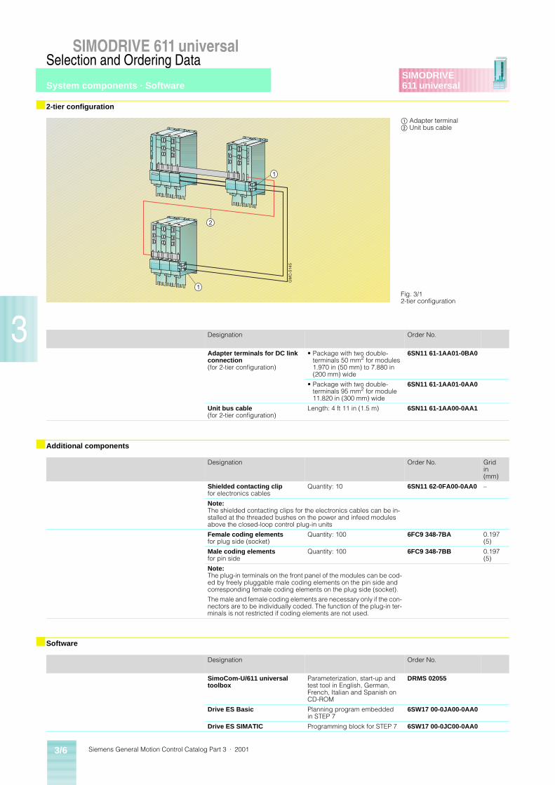
Siemens General Motion Control Catalog Part 3 · 20013/6
SIMODRIVE 611 universalSelection and Ordering Data
SIMODRIVE611 universal
3
■ 2-tier configuration
■ Additional components
■ Software
Designation Order No.
Adapter terminals for DC link connection (for 2-tier configuration)
• Package with two double-terminals 50 mm2 for modules 1.970 in (50 mm) to 7.880 in (200 mm) wide
6SN11 61-1AA01-0BA0
• Package with two double-terminals 95 mm2 for module 11.820 in (300 mm) wide
6SN11 61-1AA01-0AA0
Unit bus cable(for 2-tier configuration)
Length: 4 ft 11 in (1.5 m) 6SN11 61-1AA00-0AA1
Designation Order No. Gridin(mm)
Shielded contacting clipfor electronics cables
Quantity: 10 6SN11 62-0FA00-0AA0 –
Note:The shielded contacting clips for the electronics cables can be in-stalled at the threaded bushes on the power and infeed modules above the closed-loop control plug-in units
Female coding elementsfor plug side (socket)
Quantity: 100 6FC9 348-7BA 0.197(5)
Male coding elementsfor pin side
Quantity: 100 6FC9 348-7BB 0.197(5)
Note:The plug-in terminals on the front panel of the modules can be cod-ed by freely pluggable male coding elements on the pin side and corresponding female coding elements on the plug side (socket).
The male and female coding elements are necessary only if the con-nectors are to be individually coded. The function of the plug-in ter-minals is not restricted if coding elements are not used.
Designation Order No.
SimoCom-U/611 universal toolbox
Parameterization, start-up and test tool in English, German, French, Italian and Spanish on CD-ROM
DRMS 02055
Drive ES Basic Planning program embedded in STEP 7
6SW17 00-0JA00-0AA0
Drive ES SIMATIC Programming block for STEP 7 6SW17 00-0JC00-0AA0
Fig. 3/12-tier configuration
$ Adapter terminal% Unit bus cable
2
1
1
GM
C-5
145
System components · Software
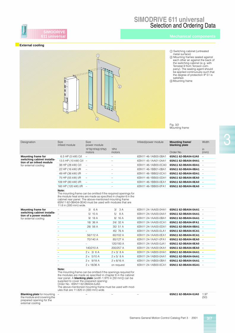
Siemens General Motion Control Catalog Part 3 · 2001 3/7
SIMODRIVE 611 universalSelection and Ordering Data
SIMODRIVE611 universal
3
■ External cooling
Designation Size infeed module
Size power module
Infeed/power module Mounting frame/ blanking plate
Width
1FT6/1FK6/1FN3 motors
1PH motors Order No.
in (mm)
Mounting frame for switching cabinet installa-tion of an infeed module for external cooling
6.5 HP (5 kW) O/I – – 6SN11 46-1AB00-0BA1 6SN11 62-0BA04-0JA0 –
13.5 HP (10 kW) O/I – – 6SN11 45-1AA01-0AA1 6SN11 62-0BA04-0HA1 –
38 HP (28 kW) O/I – – 6SN11 46-1AB00-0CA0 6SN11 62-0BA04-0DA1 –
22 HP (16 kW) I/R – – 6SN11 46-1BB01-0BA1 6SN11 62-0BA04-0BA1 –
49 HP (36 kW) I/R – – 6SN11 46-1BB02-0CA1 6SN11 62-0BA04-0DA1 –
75 HP (55 kW) I/R – – 6SN11 46-1BB00-0DA1 6SN11 62-0BA04-0EA0 –
109 HP (80 kW) I/R – – 6SN11 46-1BB00-0EA1 6SN11 62-0BA04-0EA0 –
160 HP (120 kW) I/R – – 6SN11 46-1BB00-0FA1 6SN11 62-0BA04-0EA0 –
Note:The mounting frame can be omitted if the required openings for the module heat sinks are made as specified in chapter 6 in the cabinet rear panel. The above-mentioned mounting frame 6SN11 62-0BA04-0EA0 must be used with modules that are 11.8 in (300 mm) wide.
Mounting frame for switching cabinet installa-tion of a power modulefor external cooling
– 3/ 6 A 3/ 3 A 6SN11 24-1AA00-0HA1 6SN11 62-0BA04-0AA1 –
– 5/ 10 A 5/ 8 A 6SN11 24-1AA00-0AA1 6SN11 62-0BA04-0AA1 –
– 9/ 18 A 8/ 16 A 6SN11 24-1AA00-0BA1 6SN11 62-0BA04-0AA1 –
– 18/ 36 A 24/ 32 A 6SN11 24-1AA00-0CA1 6SN11 62-0BA04-0FA1 –
– 28/ 56 A 30/ 51 A 6SN11 24-1AA00-0DA1 6SN11 62-0BA04-0BA1 –
– – 45/ 76 A 6SN11 24-1AA00-0LA1 6SN11 62-0BA04-0CA1 –
– 56/112 A 60/102 A 6SN11 24-1AA00-0EA1 6SN11 62-0BA04-0CA1 –
– 70/140 A 85/127 A 6SN11 24-1AA01-0FA1 6SN11 62-0BA04-0EA0 –
– – 120/193 A 6SN11 24-1AA00-0JA1 6SN11 62-0BA04-0EA0 –
– 140/210 A 200/257 A 6SN11 24-1AA00-0KA1 6SN11 62-0BA04-0EA0 –
– 2 x 3/ 6 A 2 x 3/ 8 A 6SN11 24-1AB00-0HA1 6SN11 62-0BA04-0AA1 –
– 2 x 5/10 A 2 x 5/ 8 A 6SN11 24-1AB00-0AA1 6SN11 62-0BA04-0AA1 –
– 2 x 9/18 A 2 x 8/16 A 6SN11 24-1AB00-0BA1 6SN11 62-0BA04-0AA1 –
– 2 x 18/36 A on request 6SN11 24-1AB00-0CA1 6SN11 62-0BA04-0GA1 –
Note:The mounting frame can be omitted if the openings required for the modules are made as specified in chapter 6 in the cabinet rear panel. A blanking plate (width 1.970 in [50 mm]) can be supplied to cover the prepared opening:Order No.: 6SN11 62-0BA04-0JA0.The above-mentioned mounting frame must be used with mod-ules that are 11.820 in (300 mm) wide.
Blanking plate for mounting the module and covering the prepared opening for the external cooling
– – – – 6SN11 62-0BA04-0JA0 1.97(50)
Fig. 3/2Mounting frame
$ Switching cabinet (untreated metal surface)
% Mounting frames sealed against each other an against the back of the switching cabinet (e.g. with Terostat-9 from Teroson com-pany). The sealing agent should be applied continuously such that the degree of protection IP 51 is satisfied.
&Mounting frame
3
2
1
GM
C-5
144
Mechanical components
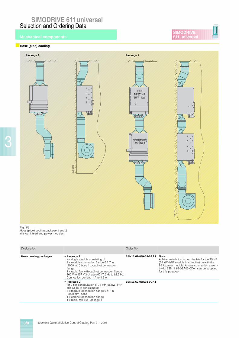
Siemens General Motion Control Catalog Part 3 · 20013/8
SIMODRIVE 611 universalSelection and Ordering Data
SIMODRIVE611 universal
3
■ Hose (pipe) cooling
Designation Order No.
Hose cooling packages • Package 1for single module consisting of 2 x module connection flange 6 ft 7 in (2000 mm) hose 1 x cabinet connection flange1 x radial fan with cabinet connection flange360 V to 457 V 3-phase AC 47.5 Hz to 62.5 HzConnection current: 1 A to 1.2 A
6SN11 62-0BA03-0AA1 Note:A 2-tier installation is permissible for the 75 HP (55 kW) I/RF module in combination with the 85 A power module. A hose connection assem-bly kit 6SN11 62-0BA03-0CA1 can be supplied for this purpose.
• Package 2for 2-tier configuration of 75 HP (55 kW) I/RF and LT 85 A consisting of 4 x module connection flange 6 ft 7 in (2000 mm) hose1 x cabinet connection flange1 x radial fan like Package 1
6SN11 62-0BA03-0CA1
Fig. 3/3Hose (pipe) cooling package 1 and 2.Without infeed and power modules!
Package 1 Package 2
GM
C-5
142
GM
C-5
143
I/RF75/97 HP55/71 kW
COD(MSD)85/110 A
Mechanical components
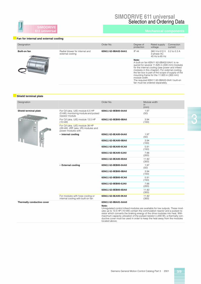
Siemens General Motion Control Catalog Part 3 · 2001 3/9
SIMODRIVE 611 universalSelection and Ordering Data
SIMODRIVE611 universal
3
■ Fan for internal and external cooling
■ Shield terminal plate
Designation Order No. Degree of protection
Rated supply voltage
Connection current
Built-on fan Radial blower for internal andexternal cooling
6SN11 62-0BA02-0AA1 IP 44 360 V to 510 V 3-phase AC 45 Hz to 65 Hz
0.2 to 0.3 A
Note:A built-on fan 6SN11 62-0BA02-0AA1 is re-quired for several 11.820 in (300 mm) modules for the internal cooling (see power and infeed modules in this chapter). For external cooling, the fan box is part of the scope of supply of the mounting frame for the 11.820 in (300 mm) module width.The required 6SN11 62-0BA02-0AA1 built-on fan must be ordered separately.
Designation Order No. Module widthin (mm)
Shield terminal plate For O/I (aka. U/E) module 6.5 HP (5 kW), monitoring module and pulsed resistor module
6SN11 62-0EB00-0AA0 1.97 (50)
For O/I (aka. U/E) module 13.5 HP (10 kW)
6SN11 62-0EB00-0BA0 3.94 (100)
For O/I (aka. U/E) module 38 HP (28 kW), I/RF (aka. I/R) modules and power modules with:
• Internal cooling 6SN11 62-0EA00-0AA0 1.97 (50)
6SN11 62-0EA00-0BA0 3.94 (100)
6SN11 62-0EA00-0CA0 5.91 (150)
6SN11 62-0EA00-0JA0 7.88 (200)
6SN11 62-0EA00-0DA0 11.82 (300)
• External cooling 6SN11 62-0EB00-0AA0 1.97 (50)
6SN11 62-0EB00-0BA0 3.94 (100)
6SN11 62-0EB00-0CA0 5.91 (150)
6SN11 62-0EB00-0JA0 7.88 (200)
6SN11 62-0EB00-0DA0 11.82 (300)
For modules with hose cooling or internal cooling with built-on fan
6SN11 62-0EA00-0KA0 11.82 (300)
Thermally conductive cover 6SN11 62-0BA01-0AA0
Note:Unregulated control infeed modules are available for low outputs. These mod-ules up to 13.5 HP (10 kW) contain the commutation reactor and a pulsed re-sistor which converts the braking energy of the drive modules into heat. With maximum capacity utilization of the pulsed resistor (>200 W), a thermally con-ductive cover must be used in order to keep the heat away from the modules located above.
Mechanical components
Siemens General Motion Control Catalog Part 3 · 20013/10
SIMODRIVE 611 universalSelection and Ordering Data
SIMODRIVE611 universal
3
■ HF commutating reactors, supply voltage 400/480 V 3-phase AC
■ Mains filters
■ Mains filters package
Assignmentto mainsinfeed module
Order No. Rated AC Power loss Max. conductor cross-section, primary/secondary side
Weight,approx.
Dimensions(W x H x D)approx.
HP(kW) A W
AWG(mm2)
lb(kg)
in(mm)
(38(28) (O/I)
6SN11 11-1AA00-0CA0 65 70 1(50)
13.2(6)
7.41 x 7.8 x 3.9(190 x 200 x 100)
(22(16) (I/RF)
6SN11 11-0AA00-0BA1 30 170 6(16)
18.7 (8.5)
12.87 x 5.65 x 5.85(330 x 145 x 150)
(49(36) (I/RF)
6SN11 11-0AA00-0CA1 67 250 1(50)
28.6(13)
12.87 x 8.97 x 5.85(330 x 230 x 150)
(75(55) (I/RF)
6SN11 11-0AA00-0DA1 103 350 210(70)
39.6(18)
12.87 x 10.92 x 5.85(330 x 280 x 150)
(109(80) (I/RF)
6SN11 11-0AA00-0EA1 150 450 FL1) 88(40)
14.82 x 9.75 x 6.63(380 x 250 x 170)
(160(120) (I/RF)
6SN11 11-0AA00-1FA0 225 590 FL1) 110(50)
14.82 x 11.32 x 6.63(380 x 290 x 170)
Assignmentto mainsinfeed module
Order No. Rated AC Power loss Max. conductor cross-section, primary/secondary side
Equipoten-tial con-nection (PE)GND
Weight,approx.
Dimensions(W x H x D)approx.
HPkW A W
AWG(mm2)
lb(kg)
in(mm)
(6.5(5) (O/I)
6SN11 11-0AA01-1BA0 16 20 12(4)
M 6, stud 8.36(3.8)
6.08 x 7.52 x 3.15(156 x 193 x 81)
(13.5(10) (O/I)
6SN11 11-0AA01-1AA0 25 20 8(10)
M 6, stud 12.54(5.7)
6.08 x 10.95 x 3.54(156 x 281 x 91)
(38(28) (O/I)
6SN11 11-0AA01-1CA0 65 25 1(50)
M 10, stud 27.5(12.5)
6.66 x 10.17 x 5.49(171 x 261 x 141)
(22(16) (I/RF)
6SN11 11-0AA01-2BA0 30 70 8(10)
M 5, stud 19.8(9)
5.07 x 18.72 x 5.83(130 x 480 x 149.5)
(49(36) (I/RF)
6SN11 11-0AA01-2CA0 67 90 1(50)
M 8, stud 35.2(16)
5.07 x 18.72 x 9.53(130 x 480 x 244.5)
(75(55) (I/RF)
6SN11 11-0AA01-2DA0 103 110 1(50)
M 8, stud 41.8(19)
5.07 x 18.72 x 10.90(130 x 480 x 279.5)
(109(80) (I/RF)
6SN11 11-0AA01-2EA0 150 150 310(95)
M 8, stud 48.4(22)
7.8 x 18.72 x 10.90(200 x 480 x 279.5)
(160(120) (I/RF)
6SN11 11-0AA01-2FA0 225 200 FL1) M 10, stud 70.4(32)
11.7 x 18.72 x 10.90(300 x 480 x 279.5)
We mainly recommend order-ing mains filter packages for I/RF modules.
• Adapter sets are available to adapt the mains filter packag-es to the assembly surface of the filter modules. The mount-
ed depth juts out of the front plane of the drive group by 0.788 in (20 mm) to 1.182 in (30 mm).
Assignmentto I/RF infeed module
Mains filter package Adapter set
HP(kW)
Order No. Order No.
(22(16)
6SN11 11-0AA01-2BB0 6SN11 62-0GA00-0BA0
(49(36)
6SN11 11-0AA01-2CB0 6SN11 62-0GA00-0CA0
(75(55)
6SN11 11-0AA01-2DB0 6SN11 62-0GA00-0DA0
(109(80)
6SN11 11-0AA01-2EB0 6SN11 62-0GA00-0EA0
(160(120)
6SN11 11-0AA01-2FB0 6SN11 62-0GA00-0EA0
1) FL = Flat termination, 0.355 in (9 mm) hole diameter.
System componentsLine side components
Siemens General Motion Control Catalog Part 3 · 2001 3/11
SIMODRIVE 611 universalSelection and Ordering Data
SIMODRIVE611 universal
3
■ Demo unit
■ Start-up box
■ Training courses
Demo unit SIMODRIVE 611 uni-versal:
• in aluminium enclosure (with wheels)
• O/I infeed module 6.5 HP(5 kW)
• 2-axis plug-in unit with resolver feedback
• PROFIBUS-DP extension board
• Two 1FK6 motors with resolver
• Start-up box
• With transformer for 110 V 60 Hz power supply
Technical data
Ordering data
The start-up box is a support device for starting up and ser-vicing SIMODRIVE 611 univer-sal controllers.
The start-up box can be con-nected to the plug-in unit. An electronic circuit within the de-vice is used for converting the 24 V DC auxiliary power supply value of the converter into an analog setpoint. The analog set-point can be adjusted and is displayed via a 5-digit LCD.
Performance characteristics of the start-up box
• Analog setting of setpoints:
– coarse and fine setting by means of two potentiometers in the ratio 1 : 10
– polarity selector switch be-tween normal and inverse setpoint polarity
– potentiometer for analog off-set value with autonomous ON/OFF switch
– ON/OFF switch for setting analog setpoints
• The analog setpoint is exten-sively decoupled and protect-ed against pole-switching within the operating voltage range.
• The analog output signal of the control terminal strip is wired to 2 mm measuring sockets in the start-up box.
• Six OFF switches for digital enabling signals, with green LED indicator lamps.
• Four red LEDs for displaying digital output signals.
Technical data
Ordering data
Contact Siemens Energy &Automation Training at www.aut.sea.siemens.com/training.
Fig. 3/4Demo unit
Designation Value
Size (L x W x H) 22 in x 10.5 in x 31 in(558 mm x 267 mm x 787 mm)
Weight 90 lb (41 kg)
Voltage supply 110 V 60 Hz, 1-phase
Designation Order No.
Demo unit 6SN11 82-0TA00-2DP0-Z
Fig. 3/5Start-up box
Designation Value
Size (L x W x H) 6.9 in x 3.5 in x 1.8 in(175 mm x 90 mm x 45 mm)
Voltage supply 24 V DC (via terminal – X101)
Voltage range, analog setpoint 0 V to 12.5 V/10 mA
Length of signal cable 4.3 ft (1.3 m)
Designation Order No.
Start-up box 9AK1014-1AA00
Demo unit and start-up box
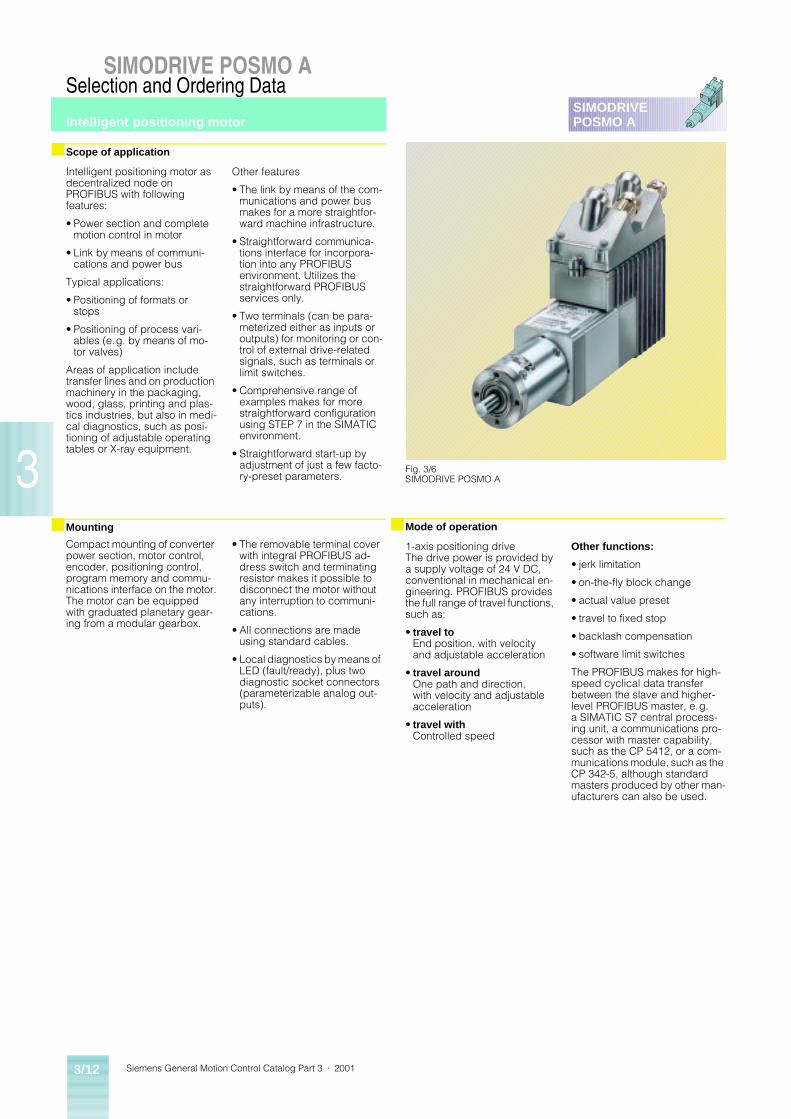
Siemens General Motion Control Catalog Part 3 · 20013/12
SIMODRIVE POSMO ASelection and Ordering Data
3
SIMODRIVEPOSMO A
Intelligent positioning motor as decentralized node on PROFIBUS with following features:
• Power section and complete motion control in motor
• Link by means of communi-cations and power bus
Typical applications:
• Positioning of formats or stops
• Positioning of process vari-ables (e.g. by means of mo-tor valves)
Areas of application include transfer lines and on production machinery in the packaging, wood, glass, printing and plas-tics industries, but also in medi-cal diagnostics, such as posi-tioning of adjustable operating tables or X-ray equipment.
Other features
• The link by means of the com-munications and power bus makes for a more straightfor-ward machine infrastructure.
• Straightforward communica-tions interface for incorpora-tion into any PROFIBUS environment. Utilizes the straightforward PROFIBUS services only.
• Two terminals (can be para-meterized either as inputs or outputs) for monitoring or con-trol of external drive-related signals, such as terminals or limit switches.
• Comprehensive range of examples makes for more straightforward configuration using STEP 7 in the SIMATIC environment.
• Straightforward start-up by adjustment of just a few facto-ry-preset parameters.
Compact mounting of converter power section, motor control, encoder, positioning control, program memory and commu-nications interface on the motor.The motor can be equipped with graduated planetary gear-ing from a modular gearbox.
• The removable terminal cover with integral PROFIBUS ad-dress switch and terminating resistor makes it possible to disconnect the motor without any interruption to communi-cations.
• All connections are made using standard cables.
• Local diagnostics by means of LED (fault/ready), plus two diagnostic socket connectors (parameterizable analog out-puts).
■ Scope of application
■ Mounting
Intelligent positioning motor
1-axis positioning driveThe drive power is provided by a supply voltage of 24 V DC, conventional in mechanical en-gineering. PROFIBUS provides the full range of travel functions, such as:
• travel toEnd position, with velocity and adjustable acceleration
• travel aroundOne path and direction, with velocity and adjustable acceleration
• travel withControlled speed
Other functions:
• jerk limitation
• on-the-fly block change
• actual value preset
• travel to fixed stop
• backlash compensation
• software limit switches
The PROFIBUS makes for high-speed cyclical data transfer between the slave and higher-level PROFIBUS master, e.g. a SIMATIC S7 central process-ing unit, a communications pro-cessor with master capability, such as the CP 5412, or a com-munications module, such as the CP 342-5, although standard masters produced by other man-ufacturers can also be used.
Fig. 3/6SIMODRIVE POSMO A
■ Mode of operation
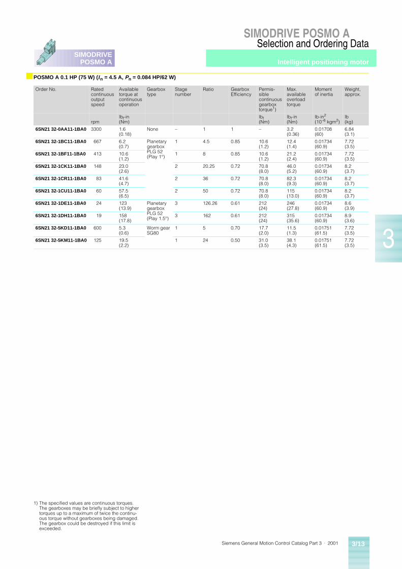
Siemens General Motion Control Catalog Part 3 · 2001 3/13
SIMODRIVE POSMO ASelection and Ordering Data
3
SIMODRIVEPOSMO A
■ POSMO A 0.1 HP (75 W) (In = 4.5 A, Pn = 0.084 HP/62 W)
Order No. Rated continuous output speed
Available torque at continuous operation
Gearbox type
Stage number
Ratio Gearbox Efficiency
Permis-sible continuous gearbox torque1)
Max. available overload torque
Moment of inertia
Weight, approx.
rpmlbf-in (Nm)
lbf (Nm)
lbf-in (Nm)
lb-in2 (10–6 kgm2)
lb(kg)
6SN21 32-0AA11-1BA0 3300 1.6(0.18)
None – 1 1 – 3.2(0.36)
0.01708(60)
6.84(3.1)
6SN21 32-1BC11-1BA0 667 6.2(0.7)
Planetary gearbox PLG 52 (Play 1°)
1 4.5 0.85 10.6(1.2)
12.4(1.4)
0.01734(60.9)
7.72(3.5)
6SN21 32-1BF11-1BA0 413 10.6(1.2)
1 8 0.85 10.6(1.2)
21.2(2.4)
0.01734(60.9)
7.72(3.5)
6SN21 32-1CK11-1BA0 148 23.0(2.6)
2 20.25 0.72 70.8(8.0)
46.0(5.2)
0.01734(60.9)
8.2(3.7)
6SN21 32-1CR11-1BA0 83 41.6(4.7)
2 36 0.72 70.8(8.0)
82.3(9.3)
0.01734(60.9)
8.2(3.7)
6SN21 32-1CU11-1BA0 60 57.5(6.5)
2 50 0.72 70.8(8.0)
115(13.0)
0.01734(60.9)
8.2(3.7)
6SN21 32-1DE11-1BA0 24 123(13.9)
Planetary gearbox PLG 52 (Play 1.5°)
3 126.26 0.61 212(24)
246(27.8)
0.01734(60.9)
8.6(3.9)
6SN21 32-1DH11-1BA0 19 158(17.8)
3 162 0.61 212(24)
315(35.6)
0.01734(60.9)
8.9(3.6)
6SN21 32-5KD11-1BA0 600 5.3(0.6)
Worm gear SG80
1 5 0.70 17.7(2.0)
11.5(1.3)
0.01751(61.5)
7.72(3.5)
6SN21 32-5KM11-1BA0 125 19.5(2.2)
1 24 0.50 31.0(3.5)
38.1(4.3)
0.01751(61.5)
7.72(3.5)
1) The specified values are continuous torques. The gearboxes may be briefly subject to higher torques up to a maximum of twice the continu-ous torque without gearboxes being damaged. The gearbox could be destroyed if this limit is exceeded.
Intelligent positioning motor
Siemens General Motion Control Catalog Part 3 · 20013/14
SIMODRIVE POSMO ASelection and Ordering Data
3
SIMODRIVEPOSMO A
■ PROFIBUS LAN cables and connectors1)
■ Power cable
SIMODRIVE POSMO A is con-trolled and parameterized via PROFIBUS-DP. Stand-alone op-eration with up to 4 individually selectable traversing blocks is possible in case the communi-cation is lost. However, to pa-rameterize these traversing blocks, a PROFIBUS connec-tion incl. PROFIBUS cables and connectors is needed.
Different types of PROFIBUS cables are available for various installation applications, e.g. trailing cables, robust cables etc. (for more information refer to chapter 2 or the Siemens cat-alog IK 10 and the electronic catalog CA01). Generally the cables listed should be used. Due to double-shielding these cables are particularly suitable for industrial environments sub-ject to electromagnetic interfer-ence.PROFIBUS FastConnect (FC) is a system for fast and easy as-sembly of PROFIBUS copper cables. The system comprises 3 compatible components:
• FastConnect bus cables for rapid installation
• FastConnect stripping tool
• FastConnect bus connector for PROFIBUS.
The maximum connectable cable cross-section to the POSMO A 0.1 HP (75 W) is AWG 12 (4 mm2). The cable outside diameter must be be-tween 0.315“ (8 mm) and 0.472“ (12 mm) to guarantee IP 55 degree of protection.
Shielding of the cable is recom-mended but not required. It can be used any 2 lead that adhere to the above mentioned limits. The 6FX50 08-5FA00-1FA0 cable is recommended.
The power for the electronics is supplied by the main power, however if bus communications and positioning sensing are to remain active even with the load power supply powered down, an optional electronics power supply can be connected (24 V ±20%).
The power leads are routed together with the PROFIBUS Cable 6ES71 94-1LY00-0AA0 or the oil resistant 6ES71 94-1LY10-0AA0.
Description Order No.
PROFIBUS FC Standard Cable
Standard type, specially designed for rapid assembly, two-wire, shielded, sold by the meter;consignment 3280 ft (1000 m) max.,min. ordering quantity 65.6 ft (20 m)
6XV18 30-0EH10
Preferred lengths
65.6 ft (20 m)164 ft (50 m)328 ft (100 m)656 ft (200 m)
1640 ft (500 m)
6XV18 30-0EN206XV18 30-0EN506XV18 30-0ET106XV18 30-0ET206XV18 30-0ET50
PROFIBUS FC Robust Cable
Two-wire, shielded, sold by the meter; consignment 3280 ft (1000 m) max., min. ordering quantity 656 ft (20 m)
6XV18 30-0JH10
PROFIBUS FC Trailing Cable
Two-wire, shielded, sold by the meter; consignment 3281 ft (1000 m) max., min. ordering quantity 65.6 ft (20 m)
6XV18 30-3EH10
PROFIBUS FastConnect
Stripping tool
Preset stripping tool for rapid stripping of insulation from PROFIBUS Fast Connect bus cables
6GK19 05-6AA00
Blade Cassettes
Spare blade cassettes for the PROFIBUS FastConnect stripping tool, 5 pieces
6GK19 05-6AB00
PROFIBUS FastConnect bus
Connector RS 485 with 90° cable outlet
With insulation displacement technique• without PG interface• with PG interface2)
6ES79 72-0BA50-0XA06ES79 72-0BB50-0XA0
Connector RS 485 with 180° cable outlet
Plug 180
6GK15 00-0FC00
1) PROFIBUS cables and connectors have been included for your convenience, please order through your auto-mation product channel.
2) D-Sub female connector on back of plug, allows to piggyback second connector.
3) According to IEC 60 204-1 1997 corrigendum 1998, at +104 °F (40 °C), installation condition C.
4) This automation product has been included for your convenience, please order through your automation product channels.
Designation Current capacity3)
Cross-section Outsidecable diameter
Order No. Weight Length
A AWG(mm2)
in(mm)
lb/ft(kg/m)
ft(m)
Power cable 31 2 x AWG 12(2 x 4 mm2)
0.42“(10.7)
6FX50 08-5FA00-1FA0 0.118(0.176)
164(50)
Power cablePVC sheath
5 1 x 2 x AWG 19(1 x 2 x 0.65 mm2)3 x 1 x AWG 18(3 x 1 x 0.75 mm2)
0.374 ± 0.02(9.5 ± 0.5)
6ES71 94-1LY00-0AA0-Z4) 0.071(0.232)
Sold by meter
Power cableOil resistant PUR sheath
5 1 x 2 x AWG 19(1 x 2 x 0.65 mm2)3 x 1 x AWG 18(3 x 1 x 0.75 mm2)
0.374 ± 0.02(9.5 ± 0.5)
6ES71 94-1LY10-0AA0-Z4) 0.071(0.232)
Sold by meter
Cables and connectors
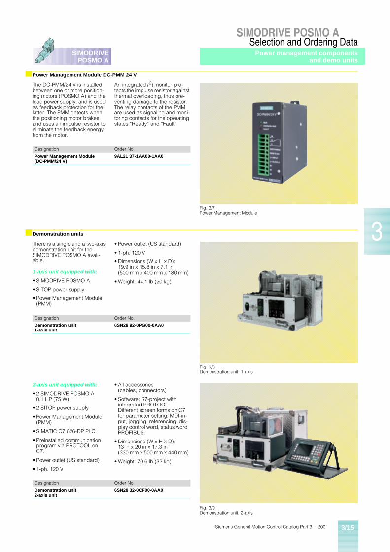
Siemens General Motion Control Catalog Part 3 · 2001 3/15
SIMODRIVE POSMO ASelection and Ordering Data
3
SIMODRIVEPOSMO A
■ Power Management Module DC-PMM 24 V
■ Demonstration units
The DC-PMM/24 V is installed between one or more position-ing motors (POSMO A) and the load power supply, and is used as feedback protection for the latter. The PMM detects when the positioning motor brakes and uses an impulse resistor to eliminate the feedback energy from the motor.
An integrated I2t monitor pro-tects the impulse resistor against thermal overloading, thus pre-venting damage to the resistor. The relay contacts of the PMM are used as signaling and moni-toring contacts for the operating states “Ready” and “Fault”.
There is a single and a two-axis demonstration unit for the SIMODRIVE POSMO A avail-able.
1-axis unit equipped with:
• SIMODRIVE POSMO A
• SITOP power supply
• Power Management Module (PMM)
• Power outlet (US standard)
• 1-ph. 120 V
• Dimensions (W x H x D):19.9 in x 15.8 in x 7.1 in (500 mm x 400 mm x 180 mm)
• Weight: 44.1 lb (20 kg)
2-axis unit equipped with:
• 2 SIMODRIVE POSMO A 0.1 HP (75 W)
• 2 SITOP power supply
• Power Management Module (PMM)
• SIMATIC C7 626-DP PLC
• Preinstalled communication program via PROTOOL on C7.
• Power outlet (US standard)
• 1-ph. 120 V
• All accessories (cables, connectors)
• Software: S7-project with integrated PROTOOL. Different screen forms on C7 for parameter setting, MDI-in-put, jogging, referencing, dis-play control word, status word PROFIBUS.
• Dimensions (W x H x D): 13 in x 20 in x 17.3 in (330 mm x 500 mm x 440 mm)
• Weight: 70.6 lb (32 kg)
Designation Order No.
Power Management Module (DC-PMM/24 V)
9AL21 37-1AA00-1AA0
Fig. 3/7Power Management Module
Designation Order No.
Demonstration unit 1-axis unit
6SN28 92-0PG00-0AA0
Fig. 3/8Demonstration unit, 1-axis
Designation Order No.
Demonstration unit 2-axis unit
6SN28 32-0CF00-0AA0
Fig. 3/9Demonstration unit, 2-axis
Power management componentsand demo units
Siemens General Motion Control Catalog Part 3 · 20013/16
SIMODRIVE POSMO ASelection and Ordering Data
3
SIMODRIVEPOSMO A
■ SITOP power
The SITOP range of 24 V power supplies has been optimized for industrial applications and op-erates on the primary pulse principle. The precise regula-tion of the output voltage makes the devices suitable even for connection to sensitive sensors.
DC/DC transformers with 600 V inputs have been developed specifically for connection to converters with a DC link. The drive energy can be used to pro-vide a continued supply to 24 V loads, even after a power failure; appropriate safety measures can therefore be implemented.
10 A and 40 A DC USV modules with external battery back-up are available to provide protection against lengthy power failures.
Technical features
• Precise output voltage
• Low residual ripple
• Large input voltage range
• High utilization factor
• Straightforward assembly
• Integrated electronic short-circuit protection
• Safe electrical isolation (SELV in accordance with EN 60 950)
• Comply with national and international standards, e.g. EMC in accordance with EN 50 081-1/-2 and EN 50 082-1/-2; UL/cUL approval
• No silicone release
Version Input Order No. Output
VoltageUe rated
Voltage range VoltageUa rated
CurrentIa rated
24 V DC/2 A; 5 A; 10 A; 20 A 1-phase CuUS1)
120 V/230 V AC 6EP13 31-2BA00 93 V – 132 V AC/187 V – 264 V AC
24 V DC± 3 %
2 A
120 V/230 V AC 6EP13 33-2BA00 93 V – 132 V AC/187 V – 264 V AC
24 V DC± 3 %
5 A
120 V/230 V AC 6EP13 34-2BA00 93 V – 132 V AC/187 V – 264 V AC
24 V DC± 3 %
10 A
120 V/230 V AC 6EP13 36-2BA00 93 V – 132 V AC/187 V – 264 V AC
24 V DC± 1 %
20 A
24 V DC/10 A; 20 A; 30 A; 40 A 3-phase CuUS1)
3-ph. 400 V – 500 V AC 6EP14 34-2BA00 3-ph. 360 V – 550 V AC 24 V DC± 3 %
10 A
3-ph. 400 V – 500 V AC 6EP14 36-2BA00 3-ph. 360 V – 550 V AC 24 V DC± 3 %
20 A
3-ph. 400 V – 500 V AC 6EP14 37-2BA00 3-ph. 360 V – 550 V AC 24 V DC± 3 %
30 A
3-ph. 400 V – 500 V AC 6EP14 37-2BA10 3-ph. 360 V – 550 V AC 24 V DC± 3 %
40 A
1) SITOP power supplies are part of the Siemens Industrial Product Division in Batavia, Illinois, please use your Products Division sales channel to order this product.
Power components
Siemens General Motion Control Catalog Part 3 · 2001 4/1
4
SIMODRIVE611 universalPOSMO A
Motor Selection
4/24/24/2
Efficiencies for synchronous Siemens High Performance Motors1FK6 Standard1FT6 Water-cooled1FT6 Self-cooled
For all other motor information see CatalogGeneral Motion Control Catalog Part 2High PerformanceMotors and Accessories
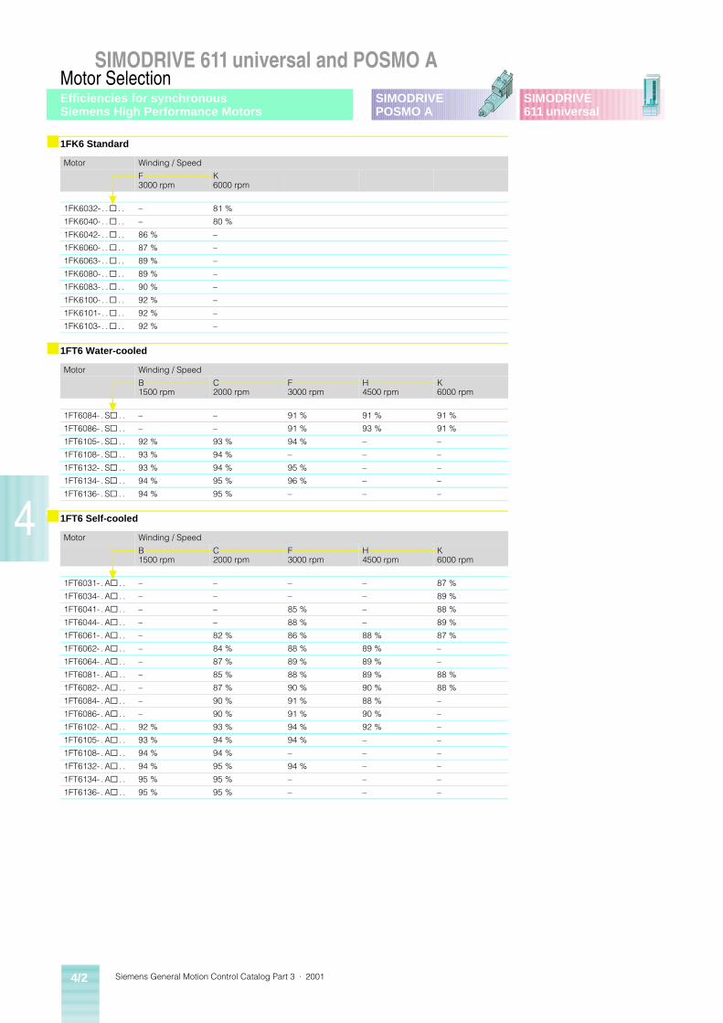
Siemens General Motion Control Catalog Part 3 · 20014/2
SIMODRIVE 611 universal and POSMO AMotor Selection
4
SIMODRIVE611 universal
SIMODRIVEPOSMO A
■ 1FK6 Standard
Motor Winding / Speed
F3000 rpm
K6000 rpm
1FK6032- . . @ . . – 81 %
1FK6040- . . @ . . – 80 %
1FK6042- . . @ . . 86 % –
1FK6060- . . @ . . 87 % –
1FK6063- . . @ . . 89 % –
1FK6080- . . @ . . 89 % –
1FK6083- . . @ . . 90 % –
1FK6100- . . @ . . 92 % –
1FK6101- . . @ . . 92 % –
1FK6103- . . @ . . 92 % –
■ 1FT6 Water-cooled
Motor Winding / Speed
B1500 rpm
C2000 rpm
F3000 rpm
H4500 rpm
K6000 rpm
1FT6084- . S@ . . – – 91 % 91 % 91 %
1FT6086- . S@ . . – – 91 % 93 % 91 %
1FT6105- . S@ . . 92 % 93 % 94 % – –
1FT6108- . S@ . . 93 % 94 % – – –
1FT6132- . S@ . . 93 % 94 % 95 % – –
1FT6134- . S@ . . 94 % 95 % 96 % – –
1FT6136- . S@ . . 94 % 95 % – – –
■ 1FT6 Self-cooled
Motor Winding / Speed
B1500 rpm
C2000 rpm
F3000 rpm
H4500 rpm
K6000 rpm
1FT6031- . A@ . . – – – – 87 %
1FT6034- . A@ . . – – – – 89 %
1FT6041- . A@ . . – – 85 % – 88 %
1FT6044- . A@ . . – – 88 % – 89 %
1FT6061- . A@ . . – 82 % 86 % 88 % 87 %
1FT6062- . A@ . . – 84 % 88 % 89 % –
1FT6064- . A@ . . – 87 % 89 % 89 % –
1FT6081- . A@ . . – 85 % 88 % 89 % 88 %
1FT6082- . A@ . . – 87 % 90 % 90 % 88 %
1FT6084- . A@ . . – 90 % 91 % 88 % –
1FT6086- . A@ . . – 90 % 91 % 90 % –
1FT6102- . A@ . . 92 % 93 % 94 % 92 % –
1FT6105- . A@ . . 93 % 94 % 94 % – –
1FT6108- . A@ . . 94 % 94 % – – –
1FT6132- . A@ . . 94 % 95 % 94 % – –
1FT6134- . A@ . . 95 % 95 % – – –
1FT6136- . A@ . . 95 % 95 % – – –
Efficiencies for synchronousSiemens High Performance Motors
Siemens General Motion Control Catalog Part 3 · 2001 5/1
5
SIMODRIVE611 universalPOSMO A
Documentation
5/25/25/25/2
OverviewGeneral documentationManufacturer/Service documentationElectronic documentationSelection & ordering data
Siemens General Motion Control Catalog Part 3 · 20015/2
SIMODRIVE 611 universal and POSMO ADocumentation
5
SIMODRIVE611 universal
SIMODRIVEPOSMO A
The documentation for the units (infeed modules, power modules, plug-in units), system components and options is supplied in German/English with the products which have been ordered.
SIMODRIVE documentation is structured as follows:
• General documentation
• Manufacturer/Service docu-mentation
• Electronic documentation
■ General documentation
These are used for selection and preliminary engineering information.
General Motion Control Catalog Part 2 · 1999
Catalog for High Performance Motors and Accessories
General Motion Control Catalog Part 3 · 2001
Catalog for SIMODRIVE 611 U and SIMODRIVE POSMO A
■ Manufacturer/Service documentation
This documentation addresses machine OEMs and service personnel who wish to use “SIMODRIVE 611 universal” with standard rotating motors in the “speed/torque setpoint” mode.
Description of Functions SIMODRIVE 611 universal
This documentation addresses machine OEMs and service personnel who wish to use “SIMODRIVE 611 universal”. This function description pro-vides detailed information on the functionality of the “SIMODRIVE 611 universal” control board.
Planning Guide SIMODRIVE 611
This guide aids in the planning of an application and gives you detailed technical information for the “SIMODRIVE 611 univer-sal”.
User Manual POSMO A
This documentation addresses machine OEMs and service personnel who wish to use “SIMODRIVE POSMO A”. This function description provides detailed information on the func-tionality of the “SIMODRIVE POSMO A”.
■ Electronic documentation
General Motion Control CD
This CD, which is delivered with each unit, contains:
• SimoComU V3.x a drives configuration software for SIMODRIVE 611 universal
• Function blocks to talk PROFIBUS with a S7 master for SIMODRIVE 611 universal
• All documentation in PDF files
• SIMOSIZE E and much more
■ Selection & ordering data
Documentation Order no.
General documentationGeneral Motion Control Catalog Part 2 · 1999 DRSP-02062
General Motion Control Catalog Part 3 · 2001 DRSP-02080
Manufacturer/Service documentationShort guide SIMODRIVE 611 universal (Brief description) 6SN11 97-0AB40-0BP2
Description of functions SIMODRIVE 611 universal 6SN11 97-0AB20-0BP2
Planning guide SIMODRIVE 611 6SN11 97-0AA00-0BP4
User Manual SIMODRIVE POSMO A, english 6SN21 97-0AA00-0BP1
Electronic documentationGeneral Motion Control CD DRMS-02055
Overview
Siemens General Motion Control Catalog Part 3 · 2001 6/1
6
SIMODRIVE611 universalPOSMO A
Engineering Information
6/26/256/276/306/326/336/34
6/366/376/396/406/426/466/636/656/676/68
SIMODRIVE 611 universalDimensioning of the power section and driveDesign SIMODRIVESystem-/Line side componentsSystem components/Infeed and power modulesSystem components/Plug-in unitsSystem components/Monitoring moduleSystem components/Braking units and braking resistorsSystem components/2-tier configurationSystem components/Cooling systemsDimensioning of the infeed moduleDimensioning of the power moduleWiring configuration overviewUnit design/Power and control terminalsPower and encoder cablesLine supply typesElectromagnetic compatibility (EMC)Technology
6/736/746/766/786/826/836/84
SIMODRIVE POSMO ASystem overview and requirementsGeneral requirementsConnecting and wiring overviewCommunicationSIMODRIVE POSMO A featuresSIMODRIVE POSMO A functionsCurrent/Torque-Speed curves for POSMO A 0.1 HP (75 W)
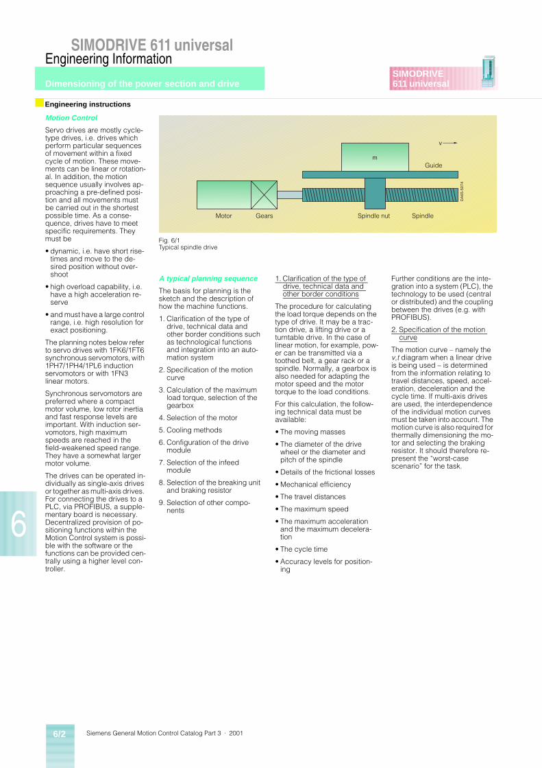
Siemens General Motion Control Catalog Part 3 · 20016/2
SIMODRIVE 611 universalEngineering Information
Dimensioning of the power section and drive
6
SIMODRIVE611 universal
Motion Control
Servo drives are mostly cycle-type drives, i.e. drives which perform particular sequences of movement within a fixed cycle of motion. These move-ments can be linear or rotation-al. In addition, the motion sequence usually involves ap-proaching a pre-defined posi-tion and all movements must be carried out in the shortest possible time. As a conse-quence, drives have to meet specific requirements. They must be
• dynamic, i.e. have short rise-times and move to the de-sired position without over-shoot
• high overload capability, i.e. have a high acceleration re-serve
• and must have a large control range, i.e. high resolution for exact positioning.
The planning notes below refer to servo drives with 1FK6/1FT6 synchronous servomotors, with 1PH7/1PH4/1PL6 induction servomotors or with 1FN3 linear motors.
Synchronous servomotors are preferred where a compact motor volume, low rotor inertia and fast response levels are important. With induction ser-vomotors, high maximum speeds are reached in the field-weakened speed range. They have a somewhat larger motor volume.
The drives can be operated in-dividually as single-axis drives or together as multi-axis drives. For connecting the drives to a PLC, via PROFIBUS, a supple-mentary board is necessary. Decentralized provision of po-sitioning functions within the Motion Control system is possi-ble with the software or the functions can be provided cen-trally using a higher level con-troller.
A typical planning sequence
The basis for planning is the sketch and the description of how the machine functions.
1. Clarification of the type of drive, technical data and other border conditions such as technological functions and integration into an auto-mation system
2. Specification of the motion curve
3. Calculation of the maximum load torque, selection of the gearbox
4. Selection of the motor
5. Cooling methods
6. Configuration of the drive module
7. Selection of the infeed module
8. Selection of the breaking unit and braking resistor
9. Selection of other compo-nents
1. Clarification of the type of drive, technical data and other border conditions
The procedure for calculating the load torque depends on the type of drive. It may be a trac-tion drive, a lifting drive or a turntable drive. In the case of linear motion, for example, pow-er can be transmitted via a toothed belt, a gear rack or a spindle. Normally, a gearbox is also needed for adapting the motor speed and the motor torque to the load conditions.
For this calculation, the follow-ing technical data must be available:
• The moving masses
• The diameter of the drive wheel or the diameter and pitch of the spindle
• Details of the frictional losses
• Mechanical efficiency
• The travel distances
• The maximum speed
• The maximum acceleration and the maximum decelera-tion
• The cycle time
• Accuracy levels for position-ing
Further conditions are the inte-gration into a system (PLC), the technology to be used (central or distributed) and the coupling between the drives (e.g. with PROFIBUS).
2. Specification of the motion curve
The motion curve – namely the v,t diagram when a linear drive is being used – is determined from the information relating to travel distances, speed, accel-eration, deceleration and the cycle time. If multi-axis drives are used, the interdependence of the individual motion curves must be taken into account. The motion curve is also required for thermally dimensioning the mo-tor and selecting the braking resistor. It should therefore re-present the “worst-case scenario” for the task.
■ Engineering instructions
DA
65-5
074
m
v
Fig. 6/1Typical spindle drive
Motor Gears Spindle
Guide
Spindle nut
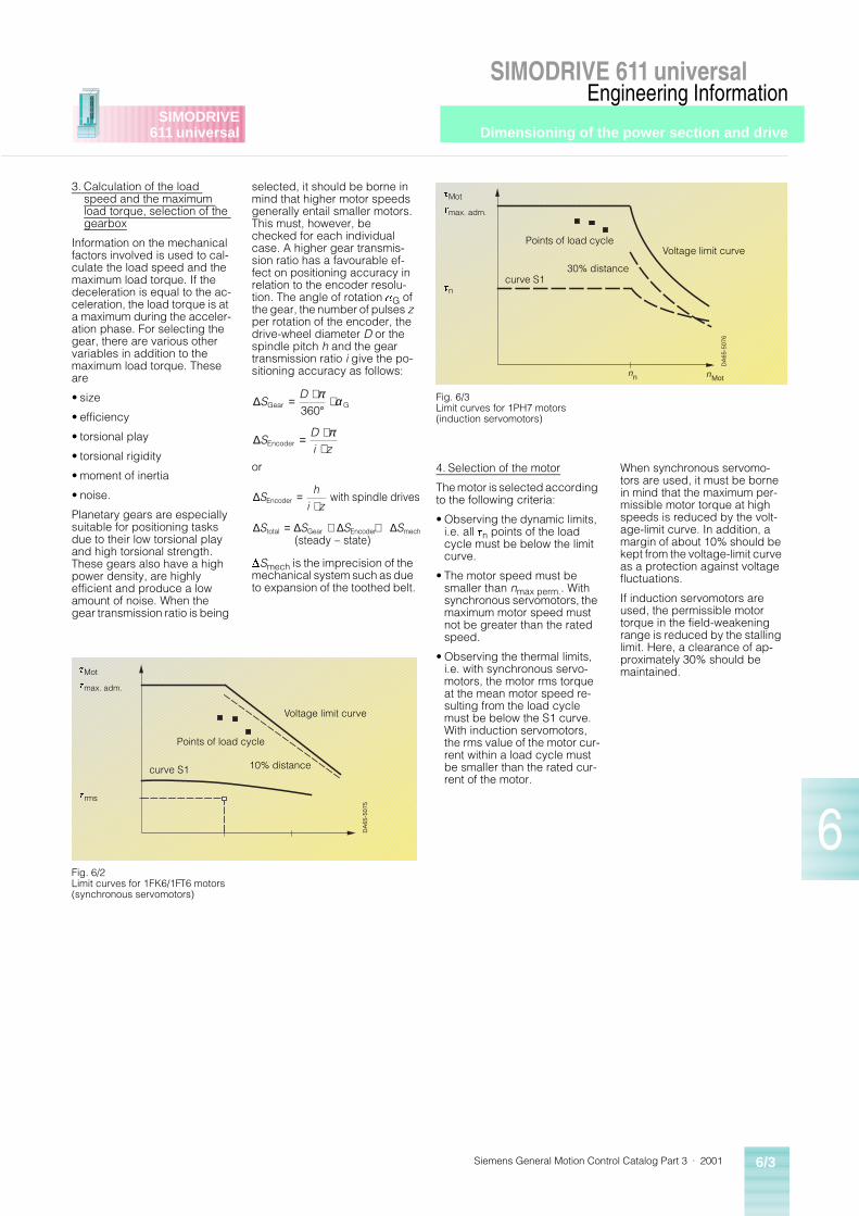
Dimensioning of the power section and drive
Siemens General Motion Control Catalog Part 3 · 2001 6/3
SIMODRIVE 611 universalEngineering Information
6
SIMODRIVE611 universal
3. Calculation of the load speed and the maximum load torque, selection of the gearbox
Information on the mechanical factors involved is used to cal-culate the load speed and the maximum load torque. If the deceleration is equal to the ac-celeration, the load torque is at a maximum during the acceler-ation phase. For selecting the gear, there are various other variables in addition to the maximum load torque. These are
• size
• efficiency
• torsional play
• torsional rigidity
• moment of inertia
• noise.
Planetary gears are especially suitable for positioning tasks due to their low torsional play and high torsional strength. These gears also have a high power density, are highly efficient and produce a low amount of noise. When the gear transmission ratio is being
selected, it should be borne in mind that higher motor speeds generally entail smaller motors. This must, however, be checked for each individual case. A higher gear transmis-sion ratio has a favourable ef-fect on positioning accuracy in relation to the encoder resolu-tion. The angle of rotation aG of the gear, the number of pulses z per rotation of the encoder, the drive-wheel diameter D or the spindle pitch h and the gear transmission ratio i give the po-sitioning accuracy as follows:
or
DSmech is the imprecision of the mechanical system such as due to expansion of the toothed belt.
4. Selection of the motor
The motor is selected according to the following criteria:
• Observing the dynamic limits, i.e. all tn points of the load cycle must be below the limit curve.
• The motor speed must be smaller than nmax perm.. With synchronous servomotors, the maximum motor speed must not be greater than the rated speed.
• Observing the thermal limits, i.e. with synchronous servo-motors, the motor rms torque at the mean motor speed re-sulting from the load cycle must be below the S1 curve. With induction servomotors, the rms value of the motor cur-rent within a load cycle must be smaller than the rated cur-rent of the motor.
When synchronous servomo-tors are used, it must be borne in mind that the maximum per-missible motor torque at high speeds is reduced by the volt-age-limit curve. In addition, a margin of about 10% should be kept from the voltage-limit curve as a protection against voltage fluctuations.
If induction servomotors are used, the permissible motor torque in the field-weakening range is reduced by the stalling limit. Here, a clearance of ap-proximately 30% should be maintained.
∆
∆
SD
SDi z
Gear G
Encoder
=⋅
°⋅
=⋅⋅
π α
π
360
∆
∆ ∆ ∆ ∆
Sh
i z
S S S S
Encoder
total Gear Encoder mech
with spindle drives
(steady – state)
=⋅
= + +
DA
65-5
076
nn nMot
Fig. 6/3Limit curves for 1PH7 motors (induction servomotors)
tMot
curve S130% distance
Voltage limit curvePoints of load cycle
tn
tmax. adm.
DA
65-5
075
Fig. 6/2Limit curves for 1FK6/1FT6 motors(synchronous servomotors)
tMot
curve S1 10% distance
Voltage limit curve
Points of load cycle
trms
tmax. adm.
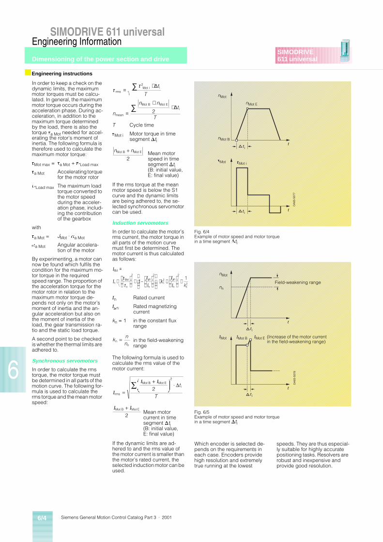
Siemens General Motion Control Catalog Part 3 · 20016/4
SIMODRIVE 611 universalEngineering Information
Dimensioning of the power section and drive
6
SIMODRIVE611 universal
In order to keep a check on the dynamic limits, the maximum motor torques must be calcu-lated. In general, the maximum motor torque occurs during the acceleration phase. During ac-celeration, in addition to the maximum torque determined by the load, there is also the torque ta Mot needed for accel-erating the rotor’s moment of inertia. The following formula is therefore used to calculate the maximum motor torque:
tMot max = ta Mot + t*Load max
ta Mot Accelerating torque for the motor rotor
t*Load max The maximum load torque converted to the motor speed during the acceler-ation phase, includ-ing the contribution of the gearbox
with
ta Mot = JMot · aa Mot
aa Mot Angular accelera-tion of the motor
By experimenting, a motor can now be found which fulfils the condition for the maximum mo-tor torque in the required speed range. The proportion of the acceleration torque for the motor rotor in relation to the maximum motor torque de-pends not only on the motor’s moment of inertia and the an-gular acceleration but also on the moment of inertia of the load, the gear transmission ra-tio and the static load torque.
A second point to be checked is whether the thermal limits are adhered to.
Synchronous servomotors
In order to calculate the rms torque, the motor torque must be determined in all parts of the motion curve. The following for-mula is used to calculate the rms torque and the mean motor speed:
T Cycle time
tMot i Motor torque in time segment Dti
Mean motor speed in time segment Dti (B: initial value, E: final value)
If the rms torque at the mean motor speed is below the S1 curve and the dynamic limits are being adhered to, the se-lected synchronous servomotor can be used.
Induction servomotors
In order to calculate the motor’s rms current, the motor torque in all parts of the motion curve must first be determined. The motor current is thus calculated as follows:
In Rated current
Imn Rated magnetizing current
kn = 1 in the constant flux range
in the field-weakening range
The following formula is used to calculate the rms value of the motor current:
Mean motor current in time segment Dti (B: initial value, E: final value)
If the dynamic limits are ad-hered to and the rms value of the motor current is smaller than the motor’s rated current, the selected induction motor can be used.
Which encoder is selected de-pends on the requirements in each case. Encoders provide high resolution and extremely true running at the lowest
speeds. They are thus especial-ly suitable for highly accurate positioning tasks. Resolvers are robust and inexpensive and provide good resolution.
■ Engineering instructions
ττ
rmsMot i i
mean
Mot B Mot Ei
=⋅
=
+⋅
∑
∑
2
2
∆
∆
t
T
n
n nt
T
n nMot B Mot E+2
I
II
I
I
I
Mot
nMot
n
n
nn
n
n n2
=
⋅
⋅
⋅ +
⋅ττ
µ µ2 2
2
2
11
– kk
knnn
n
=
I
I I
rms
Mot B Mot Ei
=
+F
HG
I
KJ ¼Ê 2
2
Dt
T
I IMot B Mot E+2
t tid
DA
65-5
077
tt id
Fig. 6/4Example of motor speed and motor torque in a time segment Dti
nMot
tMot i
nMot E
tMot
nMot B
t
t
id
DA
65-5
078
t
t id
Fig. 6/5Example of motor speed and motor torque in a time segment Dti
nMot
IMot E (Increase of the motor currentin the field-weakening range)
Field-weakening range
IMot B
nn
IMot
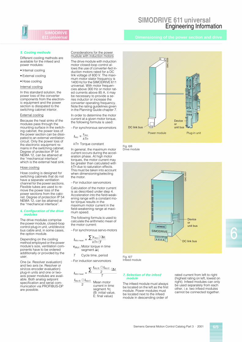
Dimensioning of the power section and drive
Siemens General Motion Control Catalog Part 3 · 2001 6/5
SIMODRIVE 611 universalEngineering Information
6
SIMODRIVE611 universal
5. Cooling methods
Different cooling methods are available for the infeed and power modules:
• Internal cooling
• External cooling
• Hose cooling
Internal cooling
In this standard solution, the power loss of the converter components from the electron-ic equipment and the power section is dissipated to the switching cabinet interior.
External cooling
Because the heat sinks of the modules pass through the mounting surface in the switch-ing cabinet, the power loss of the power section can be dissi-pated to an external ventilation circuit. Only the power loss of the electronic equipment re-mains in the switching cabinet. Degree of protection IP 54 NEMA 12, can be attained at the “mechanical interface” which is the external heat sink.
Hose cooling
Hose cooling is designed for switching cabinets that do not have a separate ventilation channel for the power sections. Flexible tubes are used to re-move the power loss of the power sections from the cabi-net. Degree of protection IP 54 NEMA 12, can be attained at the “mechanical interface”.
6. Configuration of the drive modules
The drive modules comprise the power module, closed-loop control plug-in unit, unit/device bus cable and, in some cases, the option module.
Depending on the cooling method employed or the power module’s size, ventilation com-ponents have to be ordered additionally or provided by the user.
One (w. Resolver evaluation) and two axis (w. Resolver or sin/cos encoder evaluation) plug-in units and one or two-axis power modules are avail-able. Both analog setpoint specification and serial com-munication via PROFIBUS-DP are possible.
Considerations for the power mudule with induction motors
The drive module with induction motor closed-loop control al-lows the use of converter-fed in-duction motors rated for a DC link voltage of 600 V. The maxi-mum motor stator frequency is 1400 Hz for the SIMODRIVE 611 universal. With motor frequen-cies above 300 Hz or motor rat-ed currents above 85 A, it may be necessary to provide a se-ries inductor or increase the converter operating frequency. Note the rating guidelines given in the Planning Guide chapter 7.
In order to determine the motor current at a given motor torque, the following formula is used:
– For synchronous servomotors
kTn Torque constant
In general, the maximum motor current occurs during the accel-eration phase. At high motor torques, the motor current may be greater than calculated with kTn due to saturation effects. This must be taken into account when dimensioning/selecting the motor.
– For induction servomotors
Calculation of the motor current is as described under step 4. Acceleration into the field-weak-ening range with a constant mo-tor torque results in the maximum motor current in the field-weakening range at maxi-mum speed.
The following formula is used to calculate the arithmetic mean of the motor current:
– For synchronous servo-motors
tMot i Motor torque in timesegment Dti
T Cycle time, period
– For induction servomotors
7. Selection of the infeed module
The infeed module must always be located on the left as the first module. Power modules must be located next to the infeed module in descending order of
rated current from left to right (highest rating on left, lowest on right). Infeed modules can only be used separately from each other, i.e. two infeed modules cannot be connected together.
IMotMot= τ
kTn
IMot meanMot i i=
⋅⋅
∑ τ ∆t
kTn T
I
I I
I I
Mot mean
Mot B Mot Ei
Mot B Mot E
2
2
=
+ ⋅
+
∑ ∆t
T
Mean motor current in time segment Dti (B: initial value, E: final value)
GM
C-5
006
Deviceorunit busDC link bus
Fig. 6/6Drive module
Power module Plug-in unit
GM
C-5
007
Deviceorunit bus
DC link bus
Fig. 6/7 Infeed module
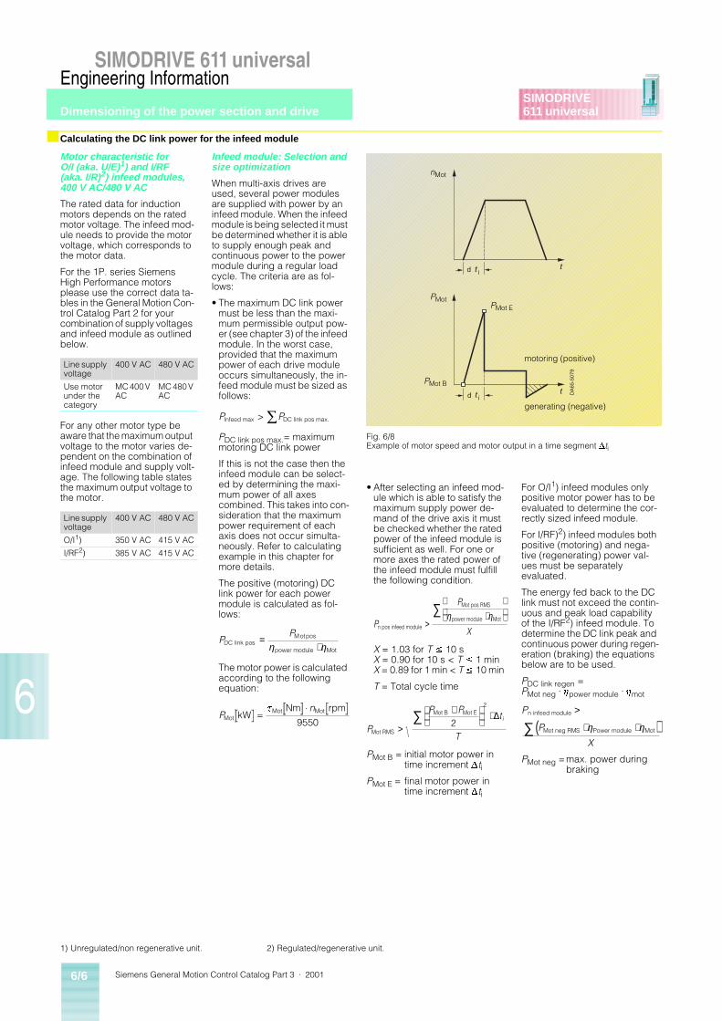
Siemens General Motion Control Catalog Part 3 · 20016/6
SIMODRIVE 611 universalEngineering Information
Dimensioning of the power section and drive
6
SIMODRIVE611 universal
■ Calculating the DC link power for the infeed module
Motor characteristic for O/I (aka. U/E)1) and I/RF (aka. I/R)2) infeed modules, 400 V AC/480 V AC
The rated data for induction motors depends on the rated motor voltage. The infeed mod-ule needs to provide the motor voltage, which corresponds to the motor data.
For the 1P. series Siemens High Performance motors please use the correct data ta-bles in the General Motion Con-trol Catalog Part 2 for your combination of supply voltages and infeed module as outlined below.
For any other motor type be aware that the maximum output voltage to the motor varies de-pendent on the combination of infeed module and supply volt-age. The following table states the maximum output voltage to the motor.
•
Infeed module: Selection and size optimization
When multi-axis drives are used, several power modules are supplied with power by an infeed module. When the infeed module is being selected it must be determined whether it is able to supply enough peak and continuous power to the power module during a regular load cycle. The criteria are as fol-lows:
• The maximum DC link power must be less than the maxi-mum permissible output pow-er (see chapter 3) of the infeed module. In the worst case, provided that the maximum power of each drive module occurs simultaneously, the in-feed module must be sized as follows:
PDC link pos max.= maximum motoring DC link power
If this is not the case then the infeed module can be select-ed by determining the maxi-mum power of all axes combined. This takes into con-sideration that the maximum power requirement of each axis does not occur simulta-neously. Refer to calculating example in this chapter for more details.
The positive (motoring) DC link power for each power module is calculated as fol-lows:
The motor power is calculated according to the following equation:
• After selecting an infeed mod-ule which is able to satisfy the maximum supply power de-mand of the drive axis it must be checked whether the rated power of the infeed module is sufficient as well. For one or more axes the rated power of the infeed module must fulfill the following condition.
X = 1.03 for T £ 10 sX = 0.90 for 10 s < T £ 1 minX = 0.89 for 1 min < T £ 10 min
T = Total cycle time
PMot B = initial motor power in time increment Dti
PMot E = final motor power in time increment Dti
For O/I1) infeed modules only positive motor power has to be evaluated to determine the cor-rectly sized infeed module.
For I/RF)2) infeed modules both positive (motoring) and nega-tive (regenerating) power val-ues must be separately evaluated.
The energy fed back to the DC link must not exceed the contin-uous and peak load capability of the I/RF2) infeed module. To determine the DC link peak and continuous power during regen-eration (braking) the equations below are to be used.
PDC link regen = PMot neg · hpower module · hmot
PMot neg =max. power duringbraking
Line supply voltage
400 V AC 480 V AC
Use motor under the category
MC 400 V AC
MC 480 V AC
Line supply voltage
400 V AC 480 V AC
O/I1) 350 V AC 415 V AC
I/RF2) 385 V AC 415 V AC
P PInfeed max DC link pos max.> Ê
PP
DC link posM ot pos
power module Mot
=⋅η η
Pn
MotMot MotkW
Nm rpm=
¼t
9550
t tid
DA
65-5
079
tt id
Fig. 6/8Example of motor speed and motor output in a time segment Dti
nMot
PMot
PMot B
PMot E
motoring (positive)
generating (negative)
P
P
Xn pos infeed module
Mot pos RMS
power module Mot>⋅
∑ η η
P
P Pt
T
i
Mot RMS
Mot B Mot E
>
+
⋅∑ 2
2
∆ P
P
X
n infeed module
Mot neg RMS Power module Mot
>
⋅ ⋅( )∑ η η
1) Unregulated/non regenerative unit. 2) Regulated/regenerative unit.
Dimensioning of the power section and drive
Siemens General Motion Control Catalog Part 3 · 2001 6/7
SIMODRIVE 611 universalEngineering Information
6
SIMODRIVE611 universal
■ Checking the 24 V DC power supply rating and braking calculations
In addition to the DC link power requirement, it is also neces-sary to check the 24 V DC pow-er supply rating of the infeed module in order to determine whether or not a monitoring module (supplemental 24 V DC supply) is needed.
The required power supply rat-ing depends on the:
• Size of the infeed/regenera-tive feedback modules.
• Size of the drive modules.
• Number of modules
The infeed or monitoring mod-ule offers a basic power supply rating for the electronics points (EP) and gating points (AP).
The power supply requirement of a drive grouping is calculat-ed by summing all of the elec-tronic points (EP) and gating points (AP) of a drive system. These values can be found in table 1, page 6/9.
If one of these values is ex-ceeded, an (additional) moni-toring module must be provided.
The monitoring module must be mounted on the left upstream of the modules to be monitored.
• DC link capacitance
Every infeed module has a maximum value which re-stricts expansion of the DC link capacitors. It must be en-sured that the DC link capac-itance in the selected drive group is not exceeded. Therefore all of the DC link capacitance of the various units in a drive system must be summed and compared to the avaliable charging limit of the infeed module. The DC link capacitance of all avail-able module and accesso-ries, including the charging limit of the infeed modules, can be found in table 1, page 6/9.
To check the 24 V DC power supply rating use table 2, page 6/11. The frequency of precharging the DC link by the infeed module is given by the following formula:
Only one infeed/regenerative feedback module or one openloop infeed module is permitted per SIMODRIVE 611u system configuration.
8. Selection of braking unitand braking resistor
For the O/I non regenerative in-feed modules the braking chop-per is included along with the resistor for the 5 kW and 10 kW ratings. The available ratings for the pulsed resistors of the O/I non regenerative infeed mod-ules are as follows:
• Infeed module 5 kW(w/internal resistor)1)
200 W continuous rating
10 kW short-time rating for 120 ms once per 10 scycle without previousload.
• Infeed module 10 kW(w/internal resistor)1)
300 W continuous rating
25 kW short-time rating for 120 ms once per 10 scycle without previousload.
• Infeed module 28 kW(external resistor needed)
max. 2 x 300 W continuous rating
max. 2 x 25 kW short-time rating for 120 msonce per 10 s cycle without previous load
max. 2 x 1.5 kW continuous rating
max. 2 x 25 kW short-time rating for 12 msonce per 10 s cycle without previous load
For the 28 kW O/I, the pulsed resistors must be ordered separately and installed exter-nally.
With greater energy feedback values, a separate pulsed resis-tor module must be provided or the feedback power must be re-duced by prolonging the brak-ing times.
Subject to certain conditions, several pulsed resistor modules can be connected in parallel.
The maximum number of pulsed resistor modules depends on the DC link capacitance of the drive configuration in question. One pulsed resistor module can be installed for every full 500 mF of DC link regenerative capaci-tance.
Only the DC link capacitance of the coupled power modules or special modules need to be tak-en into consideration for those O/I modules that already con-tain a pulsed resistor unit. If the pulsed resistor unit can be switched off, the internal DC ca-pacitance can be included in determining the dimensions of the pulsed resistor module.
As regards the braking opera-tion of the motors, check that the energy fed back to the DC link does not exceed the per-missible peak load capability of the feedback converter.
• Braking resistor selection
The selection of the braking resistor for one or more axes depends on the following cri-teria:
Ebr max Maximum braking energy [Ws]
T Total cycle time
If several axes are braked si-multaneously then the summa-tion sign has to be used. In case that only one axis is operated at a time then only the highest value for the peak power, peak energy and con-tinuous power have to be con-sidered.
For regenerative infeed mod-ules, it is possible to connect a pulsed resistor module and external braking resistor for emergency braking (i.e. in the event of a power failure).
9. Selection of other components
• Transformers
It is possible to connect the drive converter directly to a grounded (TN) line supply net-work for 3-ph. 380 to 480 V AC. For other voltages or other supply networks a transformer is required.
• Commutating reactors
HF commutating reactors are required for all infeed modules with the exception of the 5 kW and 10 kW O/I (aka. U/E) non regenerative units. The follow-ing table can be used as a guide for selecting the proper HF commutating reactor.
• RFI components (mains filters)
The mains filters are assigned to the mains infeed modules and limit the line-related emit-ted interference from the drive system. Together with the HF commutating reactor, the mains filter should also be installed near the mains infeed module, with the filter always on the mains side. Because the connecting cables are subject to high interference levels, these cables must be laid with shielding. We recom-mend using mains filter prod-ucts listed in Section 3.
No. of charging operations in 8 min =
Charging limit infeed module F
DC link capacitance of configured drive grouping F
µ
µ
[ ]
[ ]Σ
• ≥
⋅ ⋅
• ≥ ⋅ ⋅
• ≥
⋅ ⋅
=
+ ⋅
∑∑
∑∑
P
P
E P t
P
P
P
P Pt
T
max br resistor
Mot br max Mot power module
br max Mot br max br
n resistor
Mot br mean Mot power module
Mot br mean
Mot br B Mot br Ei
( )
( )
( )
η η
η η
12
2∆
Operating voltage: 3-ph. 300 to 520 V AC/45 to 65 Hz
Module HF commutating reactor
Order No.
O/I (aka. U/E)2) 28/ 50 kW 28 kW 6SN11 11-1AA00-0CA0
I/RF (aka. I/R)3) 16/ 21 kW 16 kW 6SN11 11-0AA00-0BA1
36/ 47 kW 36 kW 6SN11 11-0AA00-0CA1
55/ 71 kW 55 kW 6SN11 11-0AA00-0DA1
80/104 kW 80 kW 6SN11 11-0AA00-0EA1
120/156 kW 120 kW 6SN11 11-0AA00-0FA0
The HF commutating reactor should be installed as near as possible to the mains infeed module.
1) External resistor connection is not possible. 2) Unregulated/non regenerative unit. 3) Regulated/regenerative unit.
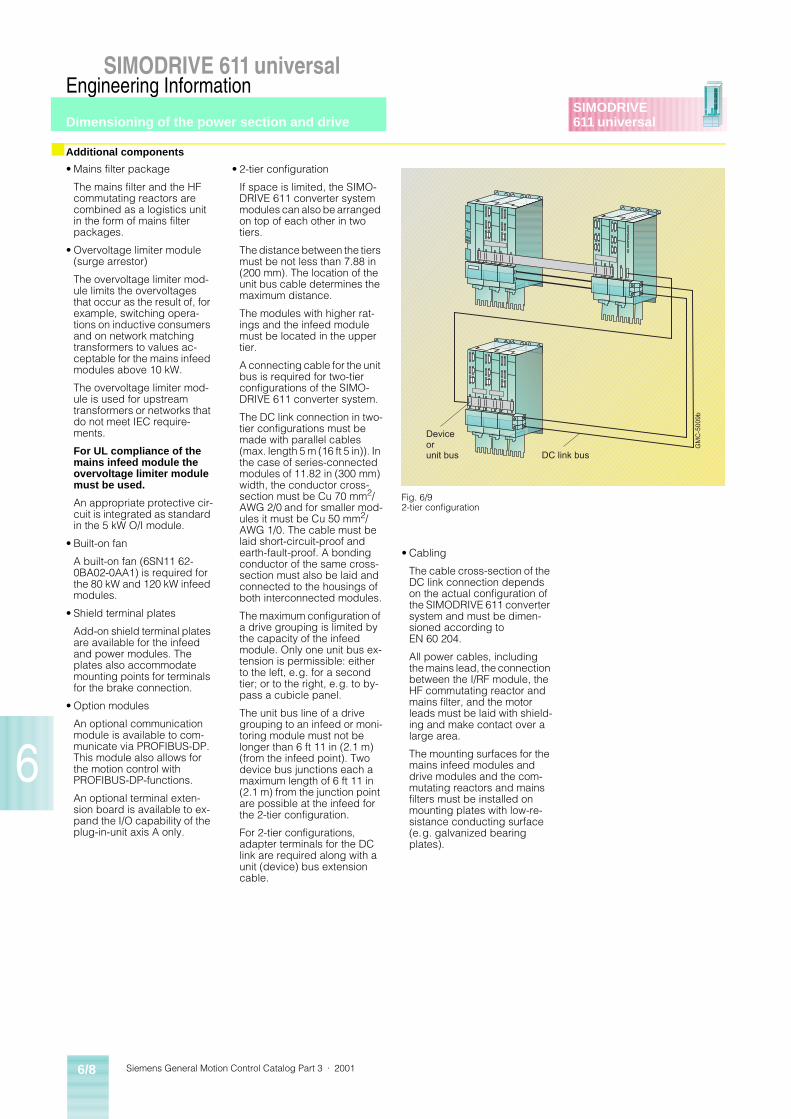
Siemens General Motion Control Catalog Part 3 · 20016/8
SIMODRIVE 611 universalEngineering Information
Dimensioning of the power section and drive
6
SIMODRIVE611 universal
■ Additional components
• Mains filter package
The mains filter and the HF commutating reactors are combined as a logistics unit in the form of mains filter packages.
• Overvoltage limiter module (surge arrestor)
The overvoltage limiter mod-ule limits the overvoltages that occur as the result of, for example, switching opera-tions on inductive consumers and on network matching transformers to values ac-ceptable for the mains infeed modules above 10 kW.
The overvoltage limiter mod-ule is used for upstream transformers or networks that do not meet IEC require-ments.
For UL compliance of the mains infeed module the overvoltage limiter module must be used.
An appropriate protective cir-cuit is integrated as standard in the 5 kW O/I module.
• Built-on fan
A built-on fan (6SN11 62-0BA02-0AA1) is required for the 80 kW and 120 kW infeed modules.
• Shield terminal plates
Add-on shield terminal plates are available for the infeed and power modules. The plates also accommodate mounting points for terminals for the brake connection.
• Option modules
An optional communication module is available to com-municate via PROFIBUS-DP. This module also allows for the motion control with PROFIBUS-DP-functions.
An optional terminal exten-sion board is available to ex-pand the I/O capability of the plug-in-unit axis A only.
• 2-tier configuration
If space is limited, the SIMO-DRIVE 611 converter system modules can also be arranged on top of each other in two tiers.
The distance between the tiers must be not less than 7.88 in (200 mm). The location of the unit bus cable determines the maximum distance.
The modules with higher rat-ings and the infeed module must be located in the upper tier.
A connecting cable for the unit bus is required for two-tier configurations of the SIMO-DRIVE 611 converter system.
The DC link connection in two-tier configurations must be made with parallel cables (max. length 5 m (16 ft 5 in)). In the case of series-connected modules of 11.82 in (300 mm) width, the conductor cross-section must be Cu 70 mm2/ AWG 2/0 and for smaller mod-ules it must be Cu 50 mm2/AWG 1/0. The cable must be laid short-circuit-proof and earth-fault-proof. A bonding conductor of the same cross-section must also be laid and connected to the housings of both interconnected modules.
The maximum configuration of a drive grouping is limited by the capacity of the infeed module. Only one unit bus ex-tension is permissible: either to the left, e.g. for a second tier; or to the right, e.g. to by-pass a cubicle panel.
The unit bus line of a drive grouping to an infeed or moni-toring module must not be longer than 6 ft 11 in (2.1 m) (from the infeed point). Two device bus junctions each a maximum length of 6 ft 11 in (2.1 m) from the junction point are possible at the infeed for the 2-tier configuration.
For 2-tier configurations, adapter terminals for the DC link are required along with a unit (device) bus extension cable.
• Cabling
The cable cross-section of the DC link connection depends on the actual configuration of the SIMODRIVE 611 converter system and must be dimen-sioned according to EN 60 204.
All power cables, including the mains lead, the connection between the I/RF module, the HF commutating reactor and mains filter, and the motor leads must be laid with shield-ing and make contact over a large area.
The mounting surfaces for the mains infeed modules and drive modules and the com-mutating reactors and mains filters must be installed on mounting plates with low-re-sistance conducting surface (e.g. galvanized bearing plates).
GM
C-5
009b
Deviceorunit bus DC link bus
Fig. 6/92-tier configuration
Dimensioning of the power section and drive
Siemens General Motion Control Catalog Part 3 · 2001 6/9
SIMODRIVE 611 universalEngineering Information
6
SIMODRIVE611 universal
■ Table 1, Assessment factors
Assessment factors of single modules for electronics points (EP) and gating points (AP) as well as permissible combina-tions of power modules and closed-loop control plug-in units.
The details for the EP and AP assessment factors refer to the approved encoder cable lengths.
• PROFIBUS-DPAn additional 0.6 EP (electron-
ics points) must be taken into consideration in the electronic area when the option is used.
• Terminal moduleNo additional electronics
points have to be taken into consideration in this case.
1) O/I (aka. U/E), unregulated/non regenerative unit.
2) I/RF (aka. I/R), regulated/regenerative unit.
Module EP and AP for the 24 V DC power supply rating DC link Capacitance
Provides Requires Provides Requires Provides Requires Limit DC link Brakingutilization
SIMODRIVE power modules with the following plug-in-units1-axis resolver 2-axis resolver 2-axis sin/cos
1 VPP/absolute encoder6SN11 18-@NJ00-0AA1 6SN11 18-@NK00-0AA1 6SN11 18-@NH00-0AA1
0: Speed/torque setpoint, 1: Speed/torque setpoint positioning1-axis version6SN11 2@-1AA00-0HA1 0
0EP 1.1AP 1.7
00
EP 1.4AP 2.0
00
EP 1.5AP 2.0
00
75 75
6SN11 2@-1AA00-0AA1 00
EP 1.1AP 1.7
00
EP 1.4AP 2.0
00
EP 1.5AP 2.0
00
75 75
6SN11 2@-1AA00-0BA1 00
EP 1.1AP 1.7
00
EP 1.4AP 2.0
00
EP 1.6AP 2.0
00
110 110
6SN11 2@-1AA00-0CA1 00
EP 1.1AP 1.7
00
EP 1.4AP 2.0
00
EP 1.6AP 2.0
00
330 330
6SN11 2@-1AA00-0DA1 00
EP 1.2AP 1.7
00
EP 1.4AP 2.0
00
EP 1.7AP 2.0
00
495 495
6SN11 2@-1AA00-0LA1 00
EP 1.7AP 1.8
00
EP 1.7AP 2.1
00
EP 1.7AP 2.1
00
495 495
6SN11 2@-1AA00-0EA1 00
EP 2.7AP 1.8
00
EP 2.7AP 2.1
00
EP 2.7AP 2.1
00
990 990
6SN11 2@-1AA01-0FA1 00
EP 2.7AP 1.9
00
EP 2.7AP 2.1
00
EP 2.7AP 2.1
00
2145 2145
6SN11 2@-1AA00-0JA1$
00
EP 1.3AP 1.9
00
EP 1.5AP 2.1
00
EP 1.7AP 2.1
00
2145 2145
6SN11 2@-1AA00-0KA1$
00
EP 1.4AP 1.9
00
EP 1.6AP 2.1
00
EP 1.8AP 2.1
00
4290 4290
6SN11 23-1AA02-0FA1$
EP 1.3AP 1.9
00
EP 1.5AP 2.1
00
EP 1.7AP 2.1
00
2145 2145
2-axis version6SN11 2@-1AB00-0HA1 0
0EP 1.3AP 2.1
00
EP 1.5AP 2.4
00
EP 1.6AP 2.4
00
150 150
6SN11 2@-1AB00-0AA1 00
EP 1.4AP 2.1
00
EP 1.7AP 2.4
00
EP 1.7AP 2.4
00
150 150
6SN11 2@-1AB00-0BA1 00
EP 1.6AP 2.1
00
EP 1.8AP 2.4
00
EP 1.8AP 2.4
00
220 220
6SN11 2@-1AB00-0CA1 00
EP 1.7AP 2.1
00
EP 1.8AP 2.4
00
EP 1.8AP 2.4
00
660 660
3: internal cooling, 4: external cooling $ With built-on fan for hose coolingSIMODRIVE infeed modulesO/I1) 5 kW/10 kW6SN11 4@-1AB00-0BA1
EP 3.5AP 7
EP 0.3AP –
EP 3.5AP 7
EP 0.3AP –
EP 3.5AP 7
EP 0.3AP –
1200 150 0
10 kW/25 kW6SN11 4@-1AA01-0AA1
EP 8AP 17
EP 0.5AP 0.5
EP 8AP 17
EP 0.5AP 0.5
EP 8AP 17
EP 0.5AP 0.5
6000 440 0
28 kW/50 kW6SN11 4@-1AA00-0CA0
EP 8AP 17
EP 0.5AP 0.5
EP 8AP 17
EP 0.5AP 0.5
EP 8AP 17
EP 0.5AP 0.5
20000 990 0
I/RF2) 16 kW/21 kW6SN11 4@-1BA01-0BA1
EP 8AP 17
EP 0.5AP 0.5
EP 8AP 17
EP 0.5AP 0.5
EP 8AP 17
EP 0.5AP 0.5
6000 495 0
36 kW/47 kW6SN11 4@-1BA02-0CA1
EP 8AP 17
EP 0.5AP 0.5
EP 8AP 17
EP 0.5AP 0.5
EP 8AP 17
EP 0.5AP 0.5
20000 990 0
55 kW/71 kW6SN11 4@-1BA01-0DA1
EP 8AP 17
EP 0.5AP 0.5
EP 8AP 17
EP 0.5AP 0.5
EP 8AP 17
EP 0.5AP 0.5
20000 2145 0
80 kW/131 kW6SN11 4@-1BB00-0EA1
EP 8AP 17
EP 1AP 0.75
EP 8AP 17
EP 1AP 0.75
EP 8AP 17
EP 1AP 0.75
20000 2145 0
120 kW/175 kW6SN11 4@-1BB00-0FA1
EP 8AP 17
EP 1AP 0.75
EP 8AP 17
EP 1AP 0.75
EP 8AP 17
EP 1AP 0.75
20000 4290 0
Monitoring module6SN11 12-1AC01-0AA1
EP 8AP 17
EP 0AP 0
EP 8AP 17
EP 0AP 0
EP 8AP 17
EP 0AP 0
00
1000 75
Pulsed resistor module6SN11 13-1AB01-0BA1
00
EP 0.2AP 0.1
00
EP 0.2AP 0.1
00
EP 0.2AP 0.1
00
75 75
5 or 6, see chapter 3
� � �
�
�
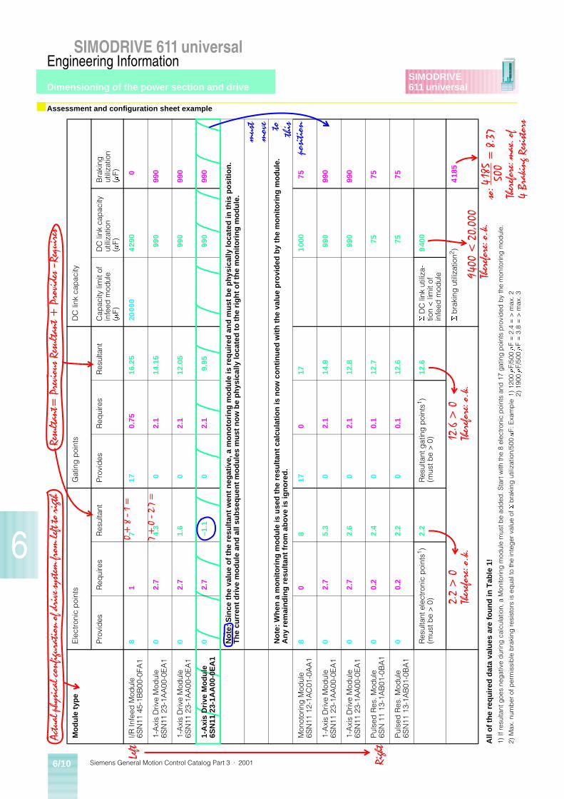
Siemens General Motion Control Catalog Part 3 · 20016/10
SIMODRIVE 611 universalEngineering Information
Dimensioning of the power section and drive
6
SIMODRIVE611 universal
■ Assessment and configuration sheet example
All
of
the
req
uir
ed d
ata
valu
es a
re f
ou
nd
in T
able
1!
1)If
resu
ltant
goe
s ne
gat
ive
dur
ing
cal
cula
tion,
a M
onito
ring
mod
ule
mus
t be
add
ed. S
tart
with
the
8 el
ectro
nic
poi
nts
and
17
gatin
g p
oint
s p
rovi
ded
by
the
mon
itorin
g m
odul
e.
2)M
ax. n
umb
er o
f per
mis
sib
le b
raki
ng re
sist
ors
is e
qua
l to
the
inte
ger
val
ue o
f S b
raki
ng u
tiliz
atio
n/50
0
m
F: E
xam
ple
1) 1
200
m
F/50
0
m
F =
2.4
= >
max
. 22)
190
0
m
F/50
0
m
F =
3.8
= >
max
. 3
Mo
du
le t
ype
Ele
ctro
nic
poi
nts
Gat
ing
poi
nts
DC
link
cap
acity
Pro
vid
esR
equi
res
Res
ulta
ntP
rovi
des
Req
uire
sR
esul
tant
Cap
acity
lim
it of
in
feed
mod
ule
(m
F)
DC
link
cap
acity
ut
iliza
tion
(m
F)
Bra
king
ut
iliza
tion
(m
F)
I/R In
feed
Mod
ule
6SN
11 4
5-1B
B00
-0FA
18
17
170.
7516
.25
2000
04
290
0
1-A
xis
Driv
e M
odul
e6S
N11
23-
1AA
00-0
EA
10
2.7
4.3
02.
114
.15
990
990
1-A
xis
Driv
e M
odul
e6S
N11
23-
1AA
00-0
EA
10
2.7
1.6
02.
112
.05
990
990
1-A
xis
Dri
ve M
od
ule
6SN
11 2
3-1A
A00
-0E
A1
02.
7–1
.10
2.1
9.95
990
990
Not
e: S
ince
the
valu
e of
the
resu
ltant
wen
t neg
ativ
e, a
mon
otor
ing
mod
ule
is r
equi
red
and
mus
t be
phys
ical
ly lo
cate
d in
this
po
sitio
n.
The
cur
rent
driv
e m
odul
e an
d al
l sub
sequ
ent m
odul
es m
ust n
ow b
e ph
ysic
ally
loca
ted
to th
e rig
ht o
f the
mon
itorin
g m
odul
e.
Not
e: W
hen
a m
onito
ring
mod
ule
is u
sed
the
resu
ltant
cal
cula
tion
is n
ow c
ontin
ued
with
the
valu
e pr
ovid
ed b
y th
e m
onito
ring
mod
ule.
A
ny r
emai
ndin
g re
sulta
nt fr
om a
bove
is ig
nore
d.
Mon
otor
ing
Mod
ule
6SN
11 1
2-1A
C01
-0A
A1
80
817
017
100
075
1-A
xis
Driv
e M
odul
e6S
N11
23-
1AA
00-0
EA
10
2.7
5.3
02.
114
.999
099
0
1-A
xis
Driv
e M
odul
e6S
N11
23-
1AA
00-0
EA
10
2.7
2.6
02.
112
.899
099
0
Pul
sed
Res
. Mod
ule
6SN
11
13-1
AB
01-0
BA
10
0.2
2.4
00.
112
.775
75
Pul
sed
Res
. Mod
ule
6SN
11 1
3-1A
B01
-0B
A1
00.
22.
20
0.1
12.6
7575
Res
ulta
nt e
lect
roni
c p
oint
s1 )(m
ust b
e >
0)
2.2
Res
ulta
nt g
atin
g p
oint
s1 )(m
ust b
e >
0)
12.6
S
DC
link
util
iza-
tion
< li
mit
of
infe
ed m
odul
e
940
0
S
bra
king
util
izat
ion2 )
418
5
$FWXDO�SK\VLFDO�FRQILJXUDWLRQ�RI�GULYH�V\VWHP�IURP�OHIW�WR�ULJWK
/HIW
5LJKW
5HVXOWDQW �3UHYLRXV�5HVXOWDQW���3URYLGHV�²5HTXLUHV
PXVW
PRYH WR WKLV
SRVLWLRQ
������²���
������²�����
����!��
7KHUHIRUH��R�N�
�����!��
7KHUHIRUH��R�N�
�������������
7KHUHIRUH��R�N�
VR������ � �����
���
7KHUHIRUH��PD[��RI�
��%UDNLQJ�5HVLVWRUV
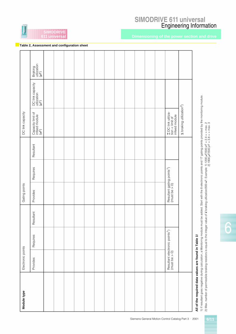
Dimensioning of the power section and drive
Siemens General Motion Control Catalog Part 3 · 2001 6/11
SIMODRIVE 611 universalEngineering Information
6
SIMODRIVE611 universal
■ Table 2, Assessment and configuration sheet
All
of
the
req
uir
ed d
ata
valu
es a
re f
ou
nd
in T
able
1!
1)If
resu
ltant
goe
s ne
gat
ive
dur
ing
cal
cula
tion,
a M
onito
ring
mod
ule
mus
t be
add
ed. S
tart
with
the
8 el
ectro
nic
poi
nts
and
17
gat
ing
poi
nts
pro
vid
ed b
y th
e m
onito
ring
mod
ule.
2)M
ax. n
umb
er o
f per
mis
sib
le b
raki
ng re
sist
ors
is e
qua
l to
the
inte
ger
val
ue o
f S
bra
king
util
izat
ion/
500
m
F: E
xam
ple
1) 1
200
m
F/50
0
m
F =
2.4
= >
max
. 22)
190
0
m
F/50
0
m
F =
3.8
= >
max
. 3
Mo
du
le t
ype
Ele
ctro
nic
poi
nts
Gat
ing
poi
nts
DC
link
cap
acity
Pro
vid
esR
equi
res
Res
ulta
ntP
rovi
des
Req
uire
sR
esul
tant
Cap
acity
lim
it of
in
feed
mod
ule
(m
F)
DC
link
cap
acity
ut
iliza
tion
(m
F)
Bra
king
ut
iliza
tion
(m
F)
Res
ulta
nt e
lect
roni
c p
oint
s1 )(m
ust b
e >
0)
Res
ulta
nt g
atin
g p
oint
s1 )(m
ust b
e >
0)
S
DC
link
util
iza-
tion
< li
mit
of
infe
ed m
odul
e
S
bra
king
util
izat
ion2 )
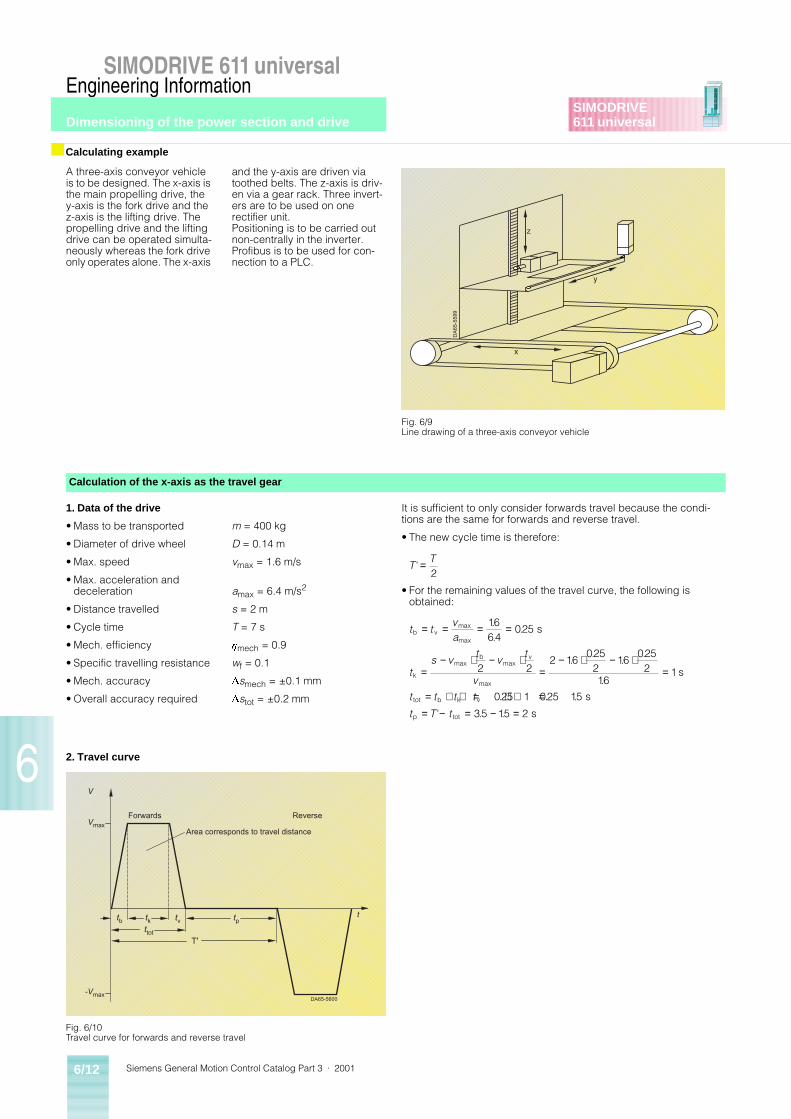
Siemens General Motion Control Catalog Part 3 · 20016/12
SIMODRIVE 611 universalEngineering Information
Dimensioning of the power section and drive
6
SIMODRIVE611 universal
A three-axis conveyor vehicle is to be designed. The x-axis is the main propelling drive, the y-axis is the fork drive and the z-axis is the lifting drive. The propelling drive and the lifting drive can be operated simulta-neously whereas the fork drive only operates alone. The x-axis
and the y-axis are driven via toothed belts. The z-axis is driv-en via a gear rack. Three invert-ers are to be used on one rectifier unit. Positioning is to be carried out non-centrally in the inverter. Profibus is to be used for con-nection to a PLC.
1. Data of the drive
• Mass to be transported
• Diameter of drive wheel
• Max. speed
• Max. acceleration and deceleration
• Distance travelled
• Cycle time
• Mech. efficiency
• Specific travelling resistance
• Mech. accuracy
• Overall accuracy required
m = 400 kg
D = 0.14 m
vmax = 1.6 m/s
amax = 6.4 m/s2
s = 2 m
T = 7 s
hmech = 0.9
wf = 0.1
Dsmech = ±0.1 mm
Dstot = ±0.2 mm
It is sufficient to only consider forwards travel because the condi-tions are the same for forwards and reverse travel.
• The new cycle time is therefore:
• For the remaining values of the travel curve, the following is obtained:
■ Calculating example
DA
65-
559
9
z
y
x
Fig. 6/9Line drawing of a three-axis conveyor vehicle
Calculation of the x-axis as the travel gear
TT
' =2
t tva
ts v
tv
t
v
t t t t
t T t
b vmax
max
k
maxb
maxv
max
tot b k v
p tot
s
s
s
s
= = = =
=− ⋅ − ⋅
=− ⋅ − ⋅
=
= + + = + + == − = − =
1664
025
2 22 16
0252
16025
216
1
025 1 025 15
35 15 2
..
.
..
..
.
. . .
' . .
Vmax
T'
t
V
-Vmax
tb tk tv tpttot
DA65-5600
Area corresponds to travel distance
Forwards Reverse
Fig. 6/10Travel curve for forwards and reverse travel
2. Travel curve
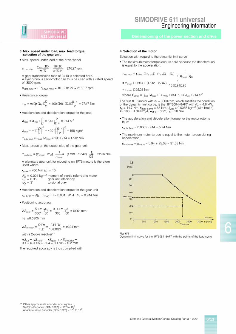
Dimensioning of the power section and drive
Siemens General Motion Control Catalog Part 3 · 2001 6/13
SIMODRIVE 611 universalEngineering Information
6
SIMODRIVE611 universal
3. Max. speed under load, max. load torque, selection of the gear unit
• Max. speed under load at the drive wheel
A gear transmission ratio of i =10 is selected here. A synchronous servomotor can thus be used with a rated speed of 3000 rpm.
nMot max = i · nLoad max = 10 · 218.27 = 2182.7 rpm
• Resistance torque
• Acceleration and deceleration torque for the load
• Max. torque on the output side of the gear unit
A planetary gear unit for mounting on 1FT6 motors is therefore used where
tmax = 400 Nm at i = 10
J*G = 0.001 kgm2 moment of inertia referred to motorhG = 0.95 gear unit efficiencyaG = 3’ torsional play
• Acceleration and deceleration torque for the gear unit
ta, br G = J*G · ·aload · i = 0.001 · 91.4 · 10 = 0.914 Nm
• Positioning accuracy
i.e. ±0.0305 mm
with a 2-pole resolver**
DStot = DSmech + DSgear + DSencoder = 0.1 + 0.0305 + 0.04 = 0.1705 < 0.2 mm
The required accuracy is thus complied with.
4. Selection of the motor
Selection with regard to the dynamic limit curve
• The maximum motor torque occurs here because the deceleration is equal to the acceleration.
The first 1FT6 motor with nn = 3000 rpm, which satisfies the condition of the dynamic limit curve, is the 1FT6084–8AF7 with Pn = 4.6 kW, tn = 14.7 Nm, tmax perm = 65 Nm, JMot = 0.0065 kgm2 (with brake), kTn100 = 1.34 Nm/A, hMot = 0.92; t0 = 20 Nm
• The acceleration and deceleration torque for the motor rotor is thus:
ta, br Mot = 0.0065 · 914 = 5.94 Nm
• The maximum motor torque is equal to the motor torque during acceleration:
tMot max = tMot a = 5.94 + 25.08 = 31.03 Nm
nv
DLoad max rpm= ⋅⋅
= ⋅⋅
=max ..
.60 16 60
01421827
π π
τ W f Nm= ⋅ ⋅ ⋅ = ⋅ ⋅ ⋅ =m g wD2
400 981 01014
22747. .
..
α α
τ α
load max–2
load2
a, br load load load
s
kgm
Nm
= ⋅ = ⋅ =
= ⋅
= ⋅
=
= ⋅ = ⋅ =
264
2014
914
2400
0142
196
196 914 1792
2 2
D
J mD
J
..
.
..
. . .
τ τ τηload max a load W
mech
Nm= + ⋅ = + ⋅ =( ) ( . . ).
.1
1792 27471
092296
∆SD
gearG
60 mm= ⋅
°⋅ = ⋅ ⋅ =π α π
360014
360360
0061.
.
∆SDi zencoder 10 1024
mm= ⋅⋅
= ⋅⋅
= ±π π014004
..
τ τ τ τ τη η
τ
τ
τ α
Mot max a Mot a br G a load Wmech G
a Mot
a Mot
a Mot Mot load Mot Mot–2
Nm
where s
= + + + ⋅⋅ ⋅
= + + + ⋅⋅ ⋅
= +
= ⋅ ⋅ = ⋅ ⋅ = ⋅
( )
. ( . . ). .
.
.
1
0914 1792 27471
10 09 0952508
914 10 914
i
J i J J
500 1000 1500 2000 2500 30000
10
20
30
40
50
60
n (rpm)nMot max
(Nm)
t
0
DA65-5601
t Mot max
Fig. 6/11Dynamic limit curve for the 1FT6084–8AF7 with the points of the load cycle
** Other approximate encoder accuraciesSin/Cos Encoder (ERN 1387) ~ 105 to 106
Absolute value Encoder (EQN 1325) ~ 105 to 106.
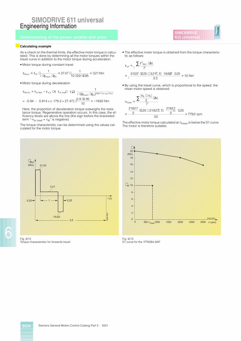
Siemens General Motion Control Catalog Part 3 · 20016/14
SIMODRIVE 611 universalEngineering Information
Dimensioning of the power section and drive
6
SIMODRIVE611 universal
As a check on the thermal limits, the effective motor torque is calcu-lated. This is done by determining all the motor torques within the travel curve in addition to the motor torque during acceleration.
• Motor torque during constant travel
• Motor torque during deceleration
Here, the proportion of deceleration torque outweighs the resis-tance torque. Regenerative operation occurs. In this case, the ef-ficiency levels are above the line (the sign before the bracketed term “–tbr load + tW” is negative).
The torque characteristic can be determined using the values cal-culated for the motor torque.
• The effective motor torque is obtained from the torque characteris-tic as follows:
• By using the travel curve, which is proportional to the speed, the mean motor speed is obtained:
The effective motor torque calculated at nmean is below the S1 curve. The motor is therefore suitable.
■ Calculating example
τ τη ηMot k W
mech G
Nm= ⋅⋅ ⋅
= ⋅⋅ ⋅
=12747
110 09 095
321i
.. .
.
τ τ τ τ τη η τ τMot br br Mot a G br load W
mech Gsign( br load W
= –5.94 – 0.914 + (–179.2 + 27.47)0.9 0.95
Nm
= − + − + ⋅⋅ ⋅
⋅ ⋅ = −
− +( )( )
.
)
1
101983
i
ττ
effMot i i
3.5 Nm
=⋅
= ⋅ + ⋅ + ⋅ =
∑ 2
2 2 23103 025 321 1 1983 02510
∆t
T '
. . . . .
n
n nt
Tmean
B Ei
rpm
=
+⋅
=⋅ + ⋅ + ⋅
=
∑ 2
218272
025 21827 121827
2025
357795
∆
'.
. ..
.
..
3,5
t (s)0,25 1 0,25
-19,83
3,21
31,03
t Mot(Nm)
DA
65-
560
2
Fig. 6/12Torque characteristic for forwards travel
500 1000 1500 2000 2500 30000
2
4
6
8
10
12
n (rpm)nmean
(Nm)
t
0
t eff
14
16
18
20
DA65-5603
Fig. 6/13S1 curve for the 1FT6084–8AF
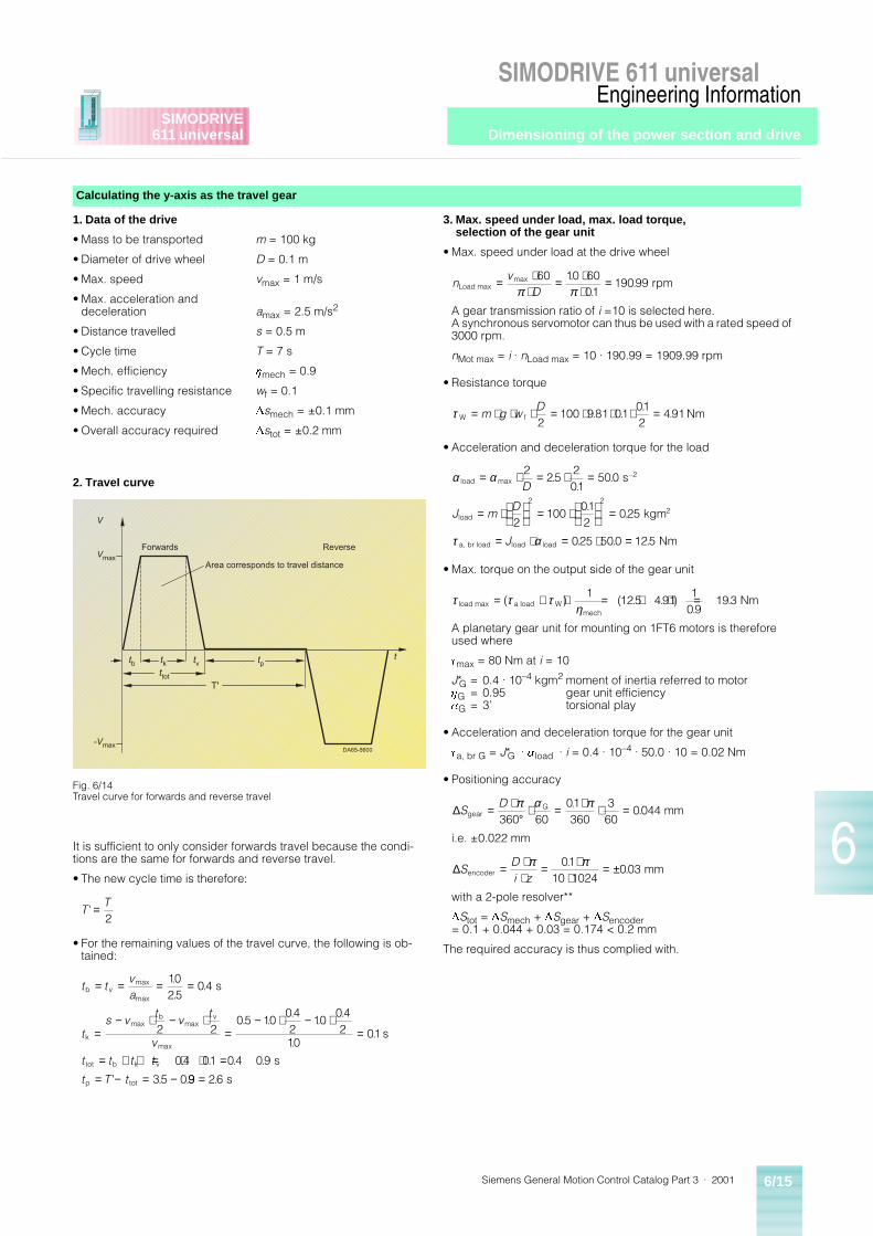
Dimensioning of the power section and drive
Siemens General Motion Control Catalog Part 3 · 2001 6/15
SIMODRIVE 611 universalEngineering Information
6
SIMODRIVE611 universal
1. Data of the drive
• Mass to be transported
• Diameter of drive wheel
• Max. speed
• Max. acceleration and deceleration
• Distance travelled
• Cycle time
• Mech. efficiency
• Specific travelling resistance
• Mech. accuracy
• Overall accuracy required
m = 100 kg
D = 0.1 m
vmax = 1 m/s
amax = 2.5 m/s2
s = 0.5 m
T = 7 s
hmech = 0.9
wf = 0.1
Dsmech = ±0.1 mm
Dstot = ±0.2 mm
3. Max. speed under load, max. load torque, selection of the gear unit
• Max. speed under load at the drive wheel
A gear transmission ratio of i =10 is selected here. A synchronous servomotor can thus be used with a rated speed of 3000 rpm.
nMot max = i · nLoad max = 10 · 190.99 = 1909.99 rpm
• Resistance torque
• Acceleration and deceleration torque for the load
• Max. torque on the output side of the gear unit
A planetary gear unit for mounting on 1FT6 motors is therefore used where
tmax = 80 Nm at i = 10
J*G = 0.4 · 10–4 kgm2 moment of inertia referred to motorhG = 0.95 gear unit efficiencyaG = 3’ torsional play
• Acceleration and deceleration torque for the gear unit
ta, br G = J*G · ·aload · i = 0.4 · 10–4 · 50.0 · 10 = 0.02 Nm
• Positioning accuracy
i.e. ±0.022 mm
with a 2-pole resolver**
DStot = DSmech + DSgear + DSencoder = 0.1 + 0.044 + 0.03 = 0.174 < 0.2 mm
The required accuracy is thus complied with.
It is sufficient to only consider forwards travel because the condi-tions are the same for forwards and reverse travel.
• The new cycle time is therefore:
• For the remaining values of the travel curve, the following is ob-tained:
Calculating the y-axis as the travel gear
nv
DLoad max rpm= ⋅⋅
= ⋅⋅
=max ..
.60 10 60
0119099
π π
τ W f Nm= ⋅ ⋅ ⋅ = ⋅ ⋅ ⋅ =m g wD2
100 981 01012
491. ..
.
α α
τ α
load max–2
load2
a, br load load load
s
kgm
Nm
= ⋅ = ⋅ =
= ⋅
= ⋅
=
= ⋅ = ⋅ =
225
201
500
2100
012
025
025 500 125
2 2
D
J mD
J
..
.
..
. . .
τ τ τηload max a load W
mech
Nm= + ⋅ = + ⋅ =( ) ( . . ).
.1
125 4911
09193
∆SD
gearG
60 mm= ⋅
°⋅ = ⋅ ⋅ =π α π
36001360
360
0044.
.
∆SDi zencoder 10 1024
mm= ⋅⋅
= ⋅⋅
= ±π π01003
..
Vmax
T'
t
V
-Vmax
tb tk tv tpttot
DA65-5600
Area corresponds to travel distance
Forwards Reverse
Fig. 6/14Travel curve for forwards and reverse travel
2. Travel curve
TT
' =2
t tva
ts v
tv
t
v
t t t t
t T t
b vmax
max
k
maxb
maxv
max
tot b k v
p tot
s
s
s
= = = =
=− ⋅ − ⋅
=− ⋅ − ⋅
=
= + + = + + == − = −
1025
04
2 205 10
042
10042
1001
04 01 04 09
35 0
..
.
. ..
..
..
. . . .
' . .99 26= . s
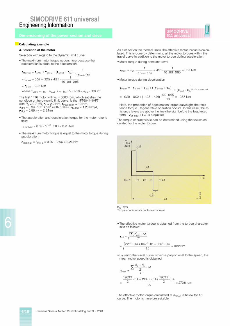
Siemens General Motion Control Catalog Part 3 · 20016/16
SIMODRIVE 611 universalEngineering Information
Dimensioning of the power section and drive
6
SIMODRIVE611 universal
4. Selection of the motor
Selection with regard to the dynamic limit curve
• The maximum motor torque occurs here because thedeceleration is equal to the acceleration.
The first 1FT6 motor with nn = 3000 rpm, which satisfies the condition or the dynamic limit curve, is the 1FT6041-4AF7 with Pn = 0.7 kW, tn = 2.2 Nm, tmax perm = 10 Nm, JMot = 0.39 ¼ 10–3 kgm2 (with brake), kTn100 = 1.26 Nm/A, hMot = 0.86; t0 = 2.5 Nm
• The acceleration and deceleration torque for the motor rotor is thus:
ta, br Mot = 0.39 ¼ 10–3 ¼ 500 = 0.20 Nm
• The maximum motor torque is equal to the motor torque during acceleration:
tMot max = tMot a = 0.20 + 2.06 = 2.26 Nm
As a check on the thermal limits, the effective motor torque is calcu-lated. This is done by determining all the motor torques within the travel curve in addition to the motor torque during acceleration.
• Motor torque during constant travel
• Motor torque during deceleration
Here, the proportion of deceleration torque outweighs the resis-tance torque. Regenerative operation occurs. In this case, the ef-ficiency levels are above the line (the sign before the bracketed term “–tbr load + tW” is negative).
The torque characteristic can be determined using the values cal-culated for the motor torque.
• The effective motor torque is obtained from the torque character-istic as follows:
• By using the travel curve, which is proportional to the speed, the mean motor speed is obtained:
The effective motor torque calculated at nmean is below the S1 curve. The motor is therefore suitable.
■ Calculating example
t t t t t
h h
t
t
t a
Mot max a Mot a br G a load Wmech G
a Mot
a Mot
a Mot Mot load Mot Mot
Nm
where s
= + + + ¼¼ ¼
= + + + ¼¼ ¼
= +
= ¼ ¼ = ¼ ¼ = ¼ -
( )
. ( . . ). .
.
.
1
002 125 4911
10 09 095206
500 10 500 2
i
J i J J
t th h
Mot k Wmech G
Nm= ¼¼ ¼
= ¼¼ ¼
=1491
110 09 095
057i
.. .
.
t t t t th h
t tMot br br Mot a G br load W
mech Gsign( br load W
Nm
= - - + - + ¼¼ ¼
= - - + - + ¼ ¼ = -
- +( )( )
. . ( . . ). .
.
)
1
020 002 125 49109 095
10087
i
3,5
t (s)0,4 0,1 0,4
-0,87
0,57
2,26
t Mot(Nm)
GM
C-5
010
Fig. 6/15Torque characteristic for forwards travel
t
t
effMot i
Nm
=¼
= ¼ + ¼ + ¼ =
Ê 2
2 2 2226 04 057 01 087 0435
082
Dt
Ti
’
. . . . . ..
.
n
n nt
Tmean
B Ei2
rpm
=
+¼
=¼ + ¼ + ¼
=
Ê D
’.
. . ..
.
..
190992
04 19099 0119099
204
352728
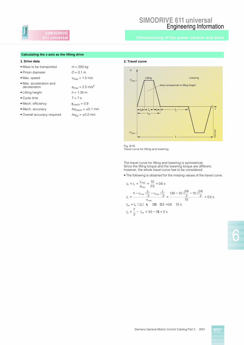
Dimensioning of the power section and drive
Siemens General Motion Control Catalog Part 3 · 2001 6/17
SIMODRIVE 611 universalEngineering Information
6
SIMODRIVE611 universal
1. Drive data
• Mass to be transported
• Pinion diameter
• Max. speed
• Max. acceleration and deceleration
• Lifting height
• Cycle time
• Mech. efficiency
• Mech. accuracy
• Overall accuracy required
m = 200 kg
D = 0.1 m
vmax = 1.5 m/s
amax = 2.5 m/s2
h = 1.35 m
T = 7 s
hmech = 0.9
Dsmech = ±0.1 mm
Dstot = ±0.2 mm
The travel curve for lifting and lowering is symmetrical. Since the lifting torque and the lowering torque are different, however, the whole travel curve has to be considered.
• The following is obtained for the missing values of the travel curve:
Calculating the z-axis as the lifting drive
Vmax
T
t
V
-Vmax
tb tk tv tpttot
Lifting
Area corresponds to lifting height
DA
65-
560
5
Lowering
Fig. 6/16Travel curve for lifting and lowering
2. Travel curve
t tva
th v
tv
t
v
t t t t
tT
t
b vmax
max
k
maxb
maxv
max
tot b k v
p tot
s
s
s
= = = =
=− ⋅ − ⋅
=− ⋅ − ⋅
=
= + + = + + =
= − = −
1525
06
2 2135 15
062
15062
1503
06 03 06 15
235 1
..
.
. ..
..
..
. . . .
. .55 2= s
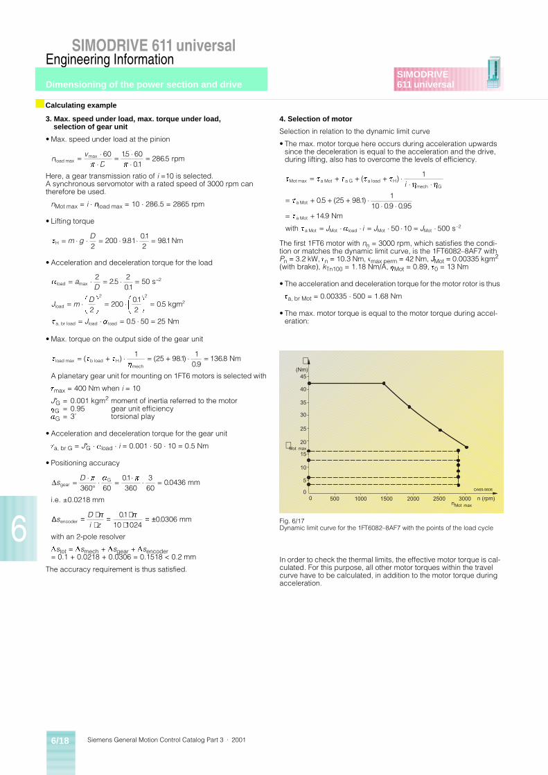
Siemens General Motion Control Catalog Part 3 · 20016/18
SIMODRIVE 611 universalEngineering Information
Dimensioning of the power section and drive
6
SIMODRIVE611 universal
3. Max. speed under load, max. torque under load, selection of gear unit
• Max. speed under load at the pinion
Here, a gear transmission ratio of i =10 is selected. A synchronous servomotor with a rated speed of 3000 rpm can therefore be used.
nMot max = i ¼ nload max = 10 ¼ 286.5 = 2865 rpm
• Lifting torque
• Acceleration and deceleration torque for the load
• Max. torque on the output side of the gear unit
A planetary gear unit for mounting on 1FT6 motors is selected with
tmax = 400 Nm when i = 10
J*G = 0.001 kgm2 moment of inertia referred to the motorhG = 0.95 gear unit efficiencyaG = 3’ torsional play
• Acceleration and deceleration torque for the gear unit
ta, br G = J*G ¼ aload ¼ i = 0.001 ¼ 50 ¼ 10 = 0.5 Nm
• Positioning accuracy
i.e. ±0.0218 mm
with an 2-pole resolver
Dstot = Dsmech + Dsgear + Dsencoder= 0.1 + 0.0218 + 0.0306 = 0.1518 < 0.2 mm
The accuracy requirement is thus satisfied.
4. Selection of motor
Selection in relation to the dynamic limit curve
• The max. motor torque here occurs during acceleration upwards since the deceleration is equal to the acceleration and the drive, during lifting, also has to overcome the levels of efficiency.
The first 1FT6 motor with nn = 3000 rpm, which satisfies the condi-tion or matches the dynamic limit curve, is the 1FT6082–8AF7 with Pn = 3.2 kW, tn = 10.3 Nm, tmax perm = 42 Nm, JMot = 0.00335 kgm2 (with brake), kTn100 = 1.18 Nm/A, hMot = 0.89, t0 = 13 Nm
• The acceleration and deceleration torque for the motor rotor is thus
ta, br Mot = 0.00335 ¼ 500 = 1.68 Nm
• The max. motor torque is equal to the motor torque during accel-eration:
In order to check the thermal limits, the effective motor torque is cal-culated. For this purpose, all other motor torques within the travel curve have to be calculated, in addition to the motor torque during acceleration.
■ Calculating example
nv
Dload max rpm= ¼¼
= ¼¼
=max ..
.60 15 60
012865
p p
tH Nm= ¼ ¼ = ¼ ¼ =m gD2
200 981012
981..
.
a
t a
load max
load
a, br load load load
s
kgm
Nm
= ¼ = ¼ =
= ¼ FHG
I
KJ = ¼ F
HG
I
KJ =
= ¼ = ¼ =
-aD
J mD
J
225
201
50
2200
012
05
05 50 25
2
2 22
..
..
.
t t th
load max b load Hmech
Nm= + ¼ = + ¼ =( ) ( . ).
.1
25 9811
091368
DsD
gearG mm= ¼
�¼ = ¼ ¼ =p a p
360 6001360
360
00436.
.
∆sDi zencoder mm= ⋅
⋅= ⋅
⋅= ±π π01
10 102400306
..
t t t t t
h h
t
t
t a
Mot max a Mot a G a load Hmech G
a Mot
a Mot
a Mot Mot load Mot Mot–2
Nm
with s
= + + + ¼¼ ¼
= + + + ¼¼ ¼
= +
= ¼ ¼ = ¼ ¼ = ¼
( )
. ( . ). .
.
1
05 25 9811
10 09 095149
50 10 500
i
J i J J
500 1000 1500 2000 2500 30000
5
10
20
25
30
35
n (rpm)nMot max
(Nm)t
0
15
40
45
DA65-5606
t Mot max
Fig. 6/17Dynamic limit curve for the 1FT6082–8AF7 with the points of the load cycle
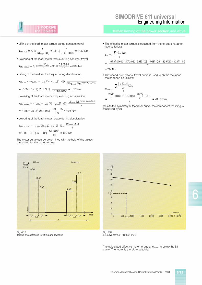
Dimensioning of the power section and drive
Siemens General Motion Control Catalog Part 3 · 2001 6/19
SIMODRIVE 611 universalEngineering Information
6
SIMODRIVE611 universal
• Lifting of the load, motor torque during constant travel
• Lowering of the load, motor torque during constant travel
• Lifting of the load, motor torque during deceleration
Lowering of the load, motor torque during acceleration
• Lowering of the load, motor torque during deceleration
The motor curve can be determined with the help of the values calculated for the motor torque.
• The effective motor torque is obtained from the torque character-istic as follows:
• The speed-proportional travel curve is used to obtain the mean motor speed as follows:
(due to the symmetry of the travel curve, the component for lifting is multiplied by 2)
The calculated effective motor torque at nmean is below the S1 curve. The motor is therefore suitable.
τ τη ηMot k up H
mech G
Nm= ⋅⋅ ⋅
= ⋅⋅ ⋅
=1981
110 09 095
1147i
.. .
.
τ τ η ηMot k down H
mech G Nm= ⋅ ⋅ = ⋅ ⋅ =i
98109 095
10839.
. ..
τ τ τ τ τη η τ τMot up br Mot br G br load H
mech Gsign(– br load H
Nm
= − − + − + ⋅⋅ ⋅
= − − + − + ⋅⋅ ⋅
=
+( )( )
. . ( . ). .
.
)
1
168 05 25 9811
10 09 095637
i
τ τ τ τ τ η η τ τ
Mot a down a Mot a G a load Hmech G
sign(– a load H
Nm
= − − + − + ⋅ ⋅
= − − + − + ⋅ ⋅ =
+( )
( )
. . ( . ). .
.
)
i
168 05 25 98109 095
10408
τ τ τ τ τ η ηMot br down br Mot br G br load H
mech G
Nm
= + + + ⋅ ⋅
= + + + ⋅ ⋅ =
( )
. . ( . ). .
.
i
168 05 25 98109 095
10127
ττ
effMot i i
2 2 2 2 2 2
Nm
=⋅
= ⋅ + ⋅ + ⋅ + ⋅ + ⋅ + ⋅
=
∑ 2
1658 06 1147 03 637 06 408 06 839 03 127 067
714
∆t
T
. . . . . . . . . . . .
.
n
n nt
Tmean
B Ei
rpm
=
+⋅
=⋅ + ⋅ + ⋅ ⋅
=
∑ 2
28652
06 2865 032865
206 2
77367
∆
. . ..
t (s)
7
(Nm)
t MotLifting
0,30,6 0,6
0,30,6 0,6
6,37
11,47
16,58
4,08
8,39
12,7
Lowering
DA
65-
560
7
Fig. 6/18Torque characteristic for lifting and lowering
500 1000 1500 2000 2500 30000
2
4
6
8
10
12
n (rpm)nmean
(Nm)t
0
t eff
14
DA65-5608
Fig. 6/19S1 curve for the 1FT6082–8AF7
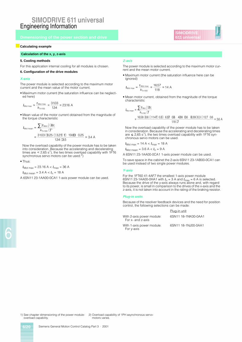
Siemens General Motion Control Catalog Part 3 · 20016/20
SIMODRIVE 611 universalEngineering Information
Dimensioning of the power section and drive
6
SIMODRIVE611 universal
5. Cooling methods
For this application internal cooling for all modules is chosen.
6. Configuration of the drive modules
X-axis
The power module is selected according to the maximum motor current and the mean value of the motor current.
• Maximum motor current (the saturation influence can be neglect-ed here)
• Mean value of the motor current obtained from the magnitude of the torque characteristic
Now the overload capability of the power module has to be taken into consideration. Because the accelerating and decelerating times are £ 2,65 s1), the two times overload capability with 1FT6 synchronous servo motors can be used.2)
• Thus:
IMot max = 23.16 A < Imax = 36 A
IMot mean = 3.4 A < In = 18 A
A 6SN11 23-1AA00-0CA1 1-axis power module can be used.
Z-axis
The power module is selected according to the maximum motor cur-rent and the mean motor current.
• Maximum motor current (the saturation influence here can be ignored)
• Mean motor current, obtained from the magnitude of the torque characteristic
Now the overload capability of the power module has to be taken in consideration. Because the accelerating and decelerating times are £ 2,65 s1), the two times overload capability with 1FT6 syn-chronous servo motors can be used.
IMot max = 14 A < Imax = 18 A
IMot mean = 3.6 A < In = 9 A
A 6SN11 23-1AA00-0CA1 1-axis power module can be used.
To save space in the cabinet the 2-axis 6SN11 23-1AB00-0CA1 can be used instead of two single power modules.
Y-axis
For the 1FT60 41-4AF7 the smallest 1-axis power module 6SN11 23-1AA00-0HA1 with In = 3 A and Imax = 6 A is selected. Because the drive of the y-axis always runs alone and, with regard to its power, is small in comparison to the drives of the x-axis and the z-axis, it is not taken into account in the rating of the braking resistor.
Plug-in units
Because of the resolver feedback devices and the need for position control, the following selections can be made:
Plug-in unit
With 2-axis power module: 6SN11 18-1NK00-0AA1For x- and z-axis
With 1-axis power module: 6SN11 18-1NJ00-0AA1For y-axis
■ Calculating example
Calculation of the x, y, z-axis
IMot maxMot max
Tn100
A≈ = =τk
3103134
2316.
..
IMot meanMot i i
Tn100
A
≈⋅
⋅
= ⋅ + ⋅ + ⋅⋅
=
∑ τ ∆t
k T '
. . . . .. .
.3103 025 321 1 1983 025
134 3534
IMot maxMot max
Tn100
A≈ = =τk
1657118
14.
.
IMot meanMot i i
Tn100
A
≈⋅
⋅
= ⋅ + ⋅ + ⋅ + ⋅ + ⋅ + ⋅⋅
=
∑ τ ∆t
k T
1658 06 1147 03 637 06 408 06 839 03 127 06118 7
36. . . . . . . . . . . .
..
1) See chapter dimensioning of the power module-overload capability.
2) Overload capability of 1PH asynchronous servo-motors varies.
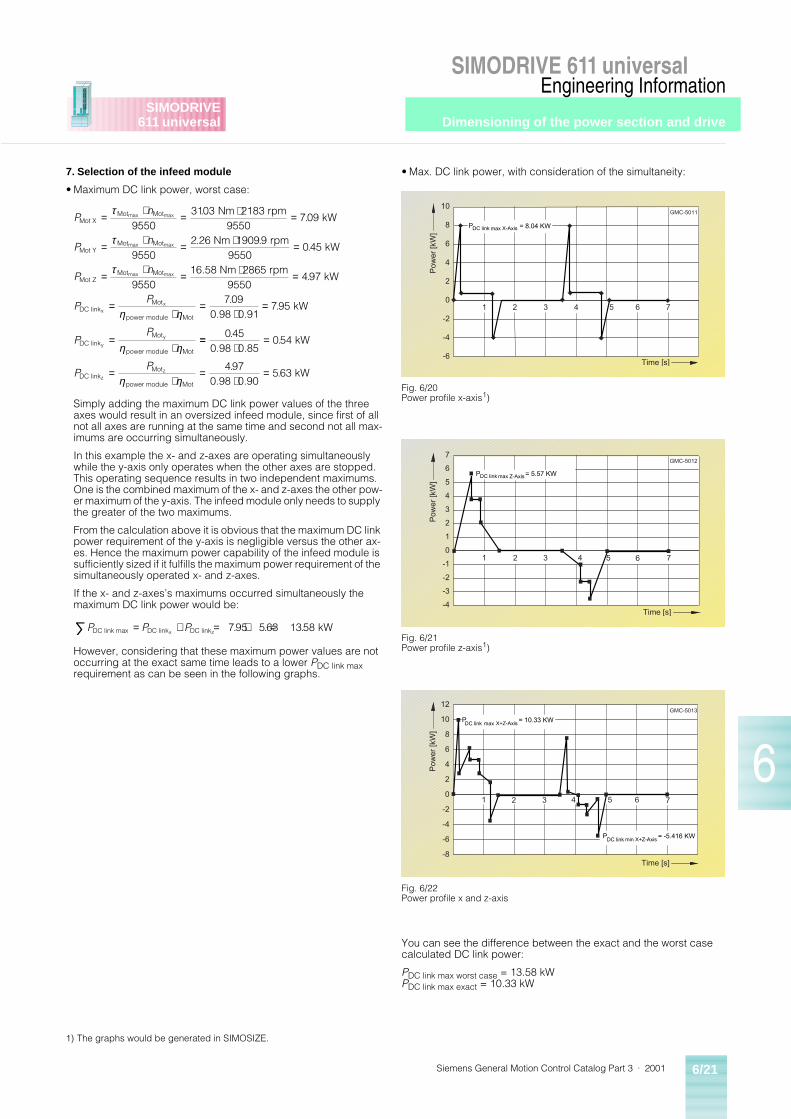
Dimensioning of the power section and drive
Siemens General Motion Control Catalog Part 3 · 2001 6/21
SIMODRIVE 611 universalEngineering Information
6
SIMODRIVE611 universal
7. Selection of the infeed module
• Maximum DC link power, worst case:
Simply adding the maximum DC link power values of the three axes would result in an oversized infeed module, since first of all not all axes are running at the same time and second not all max-imums are occurring simultaneously.
In this example the x- and z-axes are operating simultaneously while the y-axis only operates when the other axes are stopped. This operating sequence results in two independent maximums. One is the combined maximum of the x- and z-axes the other pow-er maximum of the y-axis. The infeed module only needs to supply the greater of the two maximums.
From the calculation above it is obvious that the maximum DC link power requirement of the y-axis is negligible versus the other ax-es. Hence the maximum power capability of the infeed module is sufficiently sized if it fulfills the maximum power requirement of the simultaneously operated x- and z-axes.
If the x- and z-axes’s maximums occurred simultaneously the maximum DC link power would be:
However, considering that these maximum power values are not occurring at the exact same time leads to a lower PDC link max requirement as can be seen in the following graphs.
• Max. DC link power, with consideration of the simultaneity:
You can see the difference between the exact and the worst case calculated DC link power:
PDC link max worst case = 13.58 kWPDC link max exact = 10.33 kW
Pn
Pn
Pn
PP
PP
Mot XMot Mot
Mot YMot Mot
Mot ZMot Mot
DC linkMot
power module Mot
DC linkMot
power module Mot
max max
max max
max max
xx
y
y
Nm 2183 rpm9550
kW
.26 Nm 1909 rpm9550
kW
2865 rpm9550
kW
0.98 0.91 kW
=⋅
= ⋅ =
=⋅
= ⋅ =
=⋅
= ⋅ =
=⋅
=⋅
=
=⋅
τ
τ
τ
η η
η η
95503103
709
95502 9
045
955016.58 Nm
497
709795
..
..
.
..
==⋅
=
=⋅
=⋅
=
045054
497563
..
..
0.98 0.85 kW
0.98 0.90 kWDC link
Mot
power module Motz
zPP
η η
P P PDC link max DC link DC linkx z kW= + = + =∑ 795 563 1358. . .
Fig. 6/20Power profile x-axis1)
Fig. 6/21Power profile z-axis1)
Fig. 6/22 Power profile x and z-axis
1 3 4 6
-6
-4
-2
0
2
4
6
8
10
2 5 7
Time [s]
Pow
er
[kW
]
GMC-5011
PDC link max X-Axis = 8.04 KW
1 3 4 6
-4
-3
-2
-1
0
1
2
3
4
5
7
2 5 7
Time [s]
Pow
er
[kW
]
6GMC-5012
PDC link max Z-Axis = 5.57 KW
1 3 4 6
-8
-6
-4
-2
0
2
4
6
8
10
12
2 5 7
Time [s]
Pow
er
[kW
]
GMC-5013
PDC link max X+Z-Axis = 10.33 KW
PDC link min X+Z-Axis = -5.416 KW
1) The graphs would be generated in SIMOSIZE.
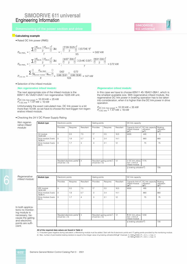
Siemens General Motion Control Catalog Part 3 · 20016/22
SIMODRIVE 611 universalEngineering Information
Dimensioning of the power section and drive
6
SIMODRIVE611 universal
• Rated DC link power (RMS)
• Selection of the infeed module
Non regenerative infeed module:
The next appropriate size of the infeed module is the 6SN11 45-1AA01-0AA1 non regenerative 10/25 kW unit.
PDC link max exact = 10.33 kW < 25 kW Pn DC link = 1.47 kW < 10 kW
Unfortunately the exact calculated max. DC link power is a bit more than 10 kW, so we have to choose the next bigger non regen-erative infeed module.
Regenerative infeed module:
In this case we have to choose 6SN11 45-1BA01-0BA1, which is the smallest available size. With regenerative infeed module, the regenerative DC link power in braking operation has to be taken into consideration, when it is higher than the DC link power in drive operation.
PDC link max exact = 10.33 kW < 35 kW Pn DC link = 1.47 kW < 16 kW
• Checking the 24 V DC Power Supply Rating
■ Calculating example
P
P Pt
T
P
P Pt
T
Mot RMS
Mot B Mot Ei
Mot RMS
Mot B Mot Ei
x
z
kW=
+
⋅=
⋅
+ ⋅=
=
+
⋅=
⋅
+ ⋅ + ⋅
∑
∑
2709 025
20734 1
35062
2497 06
2344 03
191 062
2 22
2 22
∆
∆
. .( . )
..
. .( . . )
. .
=
=⋅
= ⋅
+⋅ =
∑
2
7072
062098 091
072098 090
103147
.
.. .
.. .
..
kW
kWn DC link
Mot RMS
power module MotP
P
X
η η
Non regene-rative infeed module:
Module type Electronic points Gating points DC link capacity
Provides Requires Resultant Provides Requires Resultant Capacity limit ofinfeed module(mF)
DC link capacityutilization(mF)
Braking utilization(mF)
O/I module10/25 kW
8 0.5 7.5 17 0.5 16.5 6000 440 0
Drive module 2-axis18/36 A
0 1.8 5.7 0 2.4 14.1 660 660
Drive module 2-axis3/6 A
0 1.7 4 0 2.1 12 75 75
Resultant electronic points1)(must be > 0)
4 Resultant gating points1)(must be > 0)
12 S DC link utiliza-tion < limit of infeed module
1175
S braking utilization2) 735
All of the required data values are found in Table 1!1) If resultant goes negative during calculation, a Monitoring module must be added. Start with the 8 electronic points and 17 gating points provided by the monitoring module.2) Max. number of permissible braking resistors is equal to the integer value of S braking utilization/500 mF: Example 1) 1200 mF/500 mF = 2.4 = > max. 2
2) 1900 mF/500 mF = 3.8 = > max. 3
Regenerative infeed module:
Module type Electronic points Gating points DC link capacity
Provides Requires Resultant Provides Requires Resultant Capacity limit ofinfeed module(mF)
DC link capacityutilization(mF)
Braking utilization(mF)
I/RF module16/35 kW
8 0.5 7.5 17 0.5 16.5 6000 495 0
Drive module 2-axis18/36 A
0 1.8 5.7 0 2.4 14.1 660 660
Drive module 2-axis3/6 A
0 1.7 4 0 2.1 12 75 75
In both applica-tions no monitor-ing module is necessary, be-cause the gating and electronic points are suffi-cient.
Resultant electronic points1)(must be > 0)
4 Resultant gating points1)(must be > 0)
12 S DC link utiliza-tion < limit of infeed module
1230
S braking utilization2) 735
Dimensioning of the power section and drive
Siemens General Motion Control Catalog Part 3 · 2001 6/23
SIMODRIVE 611 universalEngineering Information
6
SIMODRIVE611 universal
8. Selection of the braking unit and braking resistor
In the 10/25 kW O/I1) infeed module an internal pulsed resistor with 300 W cont. rating and 25 kW short-time rating is included. ForI/RF2) infeed module a pulsed resistor would only be necessary for emergency braking. Because of the small load of the y-axis and it running separately, this axis does not have to be taken into consid-eration.
Non regenerative infeed module:
This means, a separate pulsed resistor 6SN11 13-1AA00-0CA0 has to be used. For the 10/25 kW O/I infeed module also a pulsed resistor module 6SN11 13-1AB01-0BA1 has to be used. The gating points, electronic points and the DC link capacitance has also to be taken into consideration.
Regenerative infeed module:No braking unit is necessary.
9. Selection of other Components
Other components can be selected as needed. For example:
• Profibus Communication module
• Shield plates, etc.
1) Non regenerative unit. 2) Regenerative unit.
P P
P P
P P P
P
P P
max br x-axis Mot br max Mot power module
max br z-axis Mot br max Mot power module
Mot br max br x-axis max br z-axis
Mot br mean x-axis
Mot br B Mot br E
kW
kW
kW
= ⋅ ⋅ =
= − ⋅ ⋅ = −
= ⋅ ⋅ =
= − ⋅ ⋅ = −
= + = − + − = −
=
+
η η
η η
453 091 098 404
381 090 098 336
404 336 74
. . . .
. . . .
. ( . ) .
22
4532
025
350155
2
1222
06 252 033812
06
70324
0155 091 0
⋅=
=
− ⋅= −
=
+ ⋅=
=
− ⋅ + − ⋅ + − ⋅= −
= ⋅ ⋅ =
= − ⋅ ⋅
∑
∑
∆
∆
t
T
P
P Pt
T
P P
i
max br mean z-axis
Mot br B Mot br Ei
n x-axis Mot br mean Mot power module
kW
kW
..
..
.. ( . ) .
..
.
. . .
η η9898 0138
0324 090 098 0286
0138 0286 0424
25 74
03 0424
= −
= ⋅ ⋅ =
= − ⋅ ⋅ = −
= + = − + − = −
≥ = ≥
≥ = ≥
.
. . . .
. ( . ) .
.
. .
kW
kW
kW
kW kW: O.K.
kW!!!: Not O.K.
n z-axis Mot br mean Mot power module
n n x-axis n z-axis
max br resistor max br
n resistor n
P P
P P P
P P
P P
η η
Siemens General Motion Control Catalog Part 3 · 20016/24
SIMODRIVE 611 universalEngineering Information
Dimensioning of the power section and drive
6
SIMODRIVE611 universal
■ Legend
Math Symbol Definition
DSGear Positioning accuracy of gear box
DSEncoder Positioning accuracy of encoder
DSmech Imprecision of the mechanical system
DSTotal Positioning accuracy of the total system
aG Angular rotation of gear box
D Diameter (in length)
p Pi
Z Pulses per revolution of encoder
i Gear ratio
nn Rated speed in RPM
ta Mot Accelerating torque needed for accelerating the motor rotor moment of inertia
t* load max Maximum load torque converted to the motor speed during the acceleration phase, including the contribution of the gearbox
tMot max Maximum motor torque
aa Mot Angular acceleration of the motor
trms Total RMS torque
tMot i Motor torque in the time segment “i”
DTi Time segment “i” in seconds
T Total cycle time
nmean Total mean speed in RPM
nMot B Beginning value of motor speed in RPM
nMot E Ending value of motor speed in RPM
JMot Inertia of motor rotor
Irms Motor RMS current
In Rated motor current
IMot Motor current at a given part of the motion curve
tmn Rated Magnetizing current
IMot B Beginning value of motor current
IMot E Ending value of motor current
Ktn Motor torque constant
Pn DC link Rated DC link power
Pn resistor Rated power pulsed resistor
PMot Motor power in kW
IDC, Rect DC bus current required by rectifier
IDC, Inv DC bus current required from inverter
VDC DC bus voltage
hInv Efficiency of inverter
hMot Efficiency of motor
Vline AC line voltage
Ws Storage capacity of capacitor in Watt*Seconds
VDC n Rated DC bus voltage
VDC min Minimum allowable DC bus voltage
tMot br max Maximum motor torque during braking
trt Power dip ride through time
Pbr max Maximum braking power
tbr Braking time
Wbr Braking energy
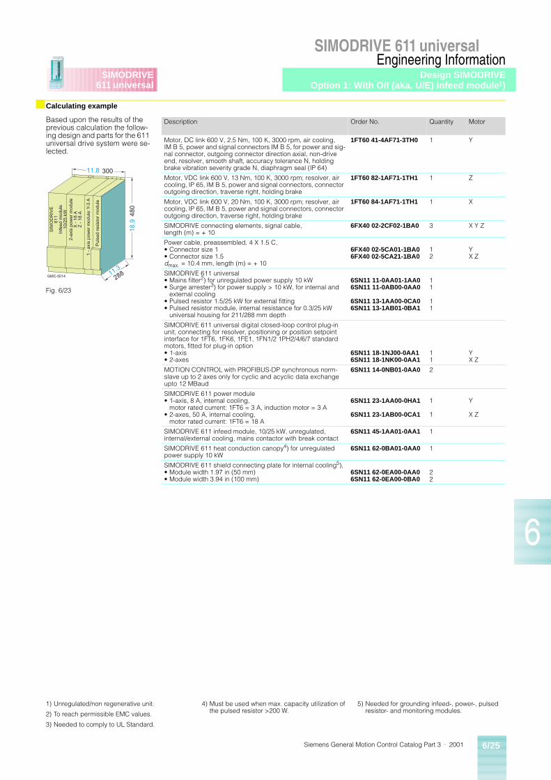
Siemens General Motion Control Catalog Part 3 · 2001 6/25
SIMODRIVE 611 universalEngineering Information
6
SIMODRIVE611 universal
■ Calculating example
Based upon the results of the previous calculation the follow-ing design and parts for the 611 universal drive system were se-lected.
Description Order No. Quantity Motor
Motor, DC link 600 V, 2.5 Nm, 100 K, 3000 rpm, air cooling, IM B 5, power and signal connectors IM B 5, for power and sig-nal connector, outgoing connector direction axial, non-drive end, resolver, smooth shaft, accuracy tolerance N, holding brake vibration severity grade N, diaphragm seal (IP 64)
1FT60 41-4AF71-3TH0 1 Y
Motor, VDC link 600 V, 13 Nm, 100 K, 3000 rpm; resolver, air cooling, IP 65, IM B 5, power and signal connectors, connector outgoing direction, traverse right, holding brake
1FT60 82-1AF71-1TH1 1 Z
Motor, VDC link 600 V, 20 Nm, 100 K, 3000 rpm; resolver, air cooling, IP 65, IM B 5, power and signal connectors, connector outgoing direction, traverse right, holding brake
1FT60 84-1AF71-1TH1 1 X
SIMODRIVE connecting elements, signal cable, length (m) = + 10
6FX40 02-2CF02-1BA0 3 X Y Z
Power cable, preassembled, 4 X 1.5 C,• Connector size 1• Connector size 1.5dmax. = 10.4 mm, length (m) = + 10
6FX40 02-5CA01-1BA06FX40 02-5CA21-1BA0
12
YX Z
SIMODRIVE 611 universal• Mains filter2) for unregulated power supply 10 kW• Surge arrester3) for power supply > 10 kW, for internal and
external cooling• Pulsed resistor 1.5/25 kW for external fitting• Pulsed resistor module, internal resistance for 0.3/25 kW
universal housing for 211/288 mm depth
6SN11 11-0AA01-1AA06SN11 11-0AB00-0AA0
6SN11 13-1AA00-0CA06SN11 13-1AB01-0BA1
11
11
SIMODRIVE 611 universal digital closed-loop control plug-in unit, connecting for resolver, positioning or position setpoint interface for 1FT6, 1FK6, 1FE1, 1FN1/2 1PH2/4/6/7 standard motors, fitted for plug-in option• 1-axis• 2-axes
6SN11 18-1NJ00-0AA16SN11 18-1NK00-0AA1
11
YX Z
MOTION CONTROL with PROFIBUS-DP synchronous norm-slave up to 2 axes only for cyclic and acyclic data exchange upto 12 MBaud
6SN11 14-0NB01-0AA0 2
SIMODRIVE 611 power module• 1-axis, 8 A, internal cooling,
motor rated current: 1FT6 = 3 A, induction motor = 3 A• 2-axes, 50 A, internal cooling,
motor rated current: 1FT6 = 18 A
6SN11 23-1AA00-0HA1
6SN11 23-1AB00-0CA1
1
1
Y
X Z
SIMODRIVE 611 infeed module, 10/25 kW, unregulated, internal/external cooling, mains contactor with break contact
6SN11 45-1AA01-0AA1 1
SIMODRIVE 611 heat conduction canopy4) for unregulated power supply 10 kW
6SN11 62-0BA01-0AA0 1
SIMODRIVE 611 shield connecting plate for internal cooling5),• Module width 1.97 in (50 mm)• Module width 3.94 in (100 mm)
6SN11 62-0EA00-0AA06SN11 62-0EA00-0BA0
22
GMC-5014
300
480
288
11.8
11.3
SIM
OD
RIV
E61
1In
feed
mod
ule
10/2
5 kW
2-ax
is p
ower
mod
ule
X -
18
AZ
- 1
8 A
1 -
axis
pow
er m
odul
e: Y
-3 A
Pul
sed
resi
stor
mod
ule
18.9
Fig. 6/23
1) Unregulated/non regenerative unit.
2) To reach permissible EMC values.
3) Needed to comply to UL Standard.
4) Must be used when max. capacity utilization of the pulsed resistor >200 W.
5) Needed for grounding infeed-, power-, pulsed resistor- and monitoring modules.
Design SIMODRIVEOption 1: With O/I (aka. U/E) infeed module1)
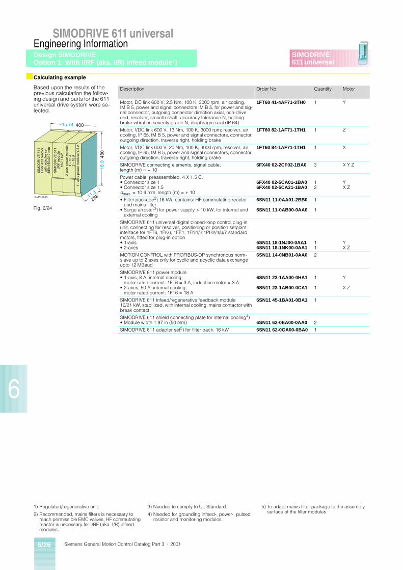
Siemens General Motion Control Catalog Part 3 · 20016/26
SIMODRIVE 611 universalEngineering Information
6
SIMODRIVE611 universal
■ Calculating example
Based upon the results of the previous calculation the follow-ing design and parts for the 611 universal drive system were se-lected.
Description Order No. Quantity Motor
Motor, DC link 600 V, 2.5 Nm, 100 K, 3000 rpm, air cooling, IM B 5, power and signal connectors IM B 5, for power and sig-nal connector, outgoing connector direction axial, non-drive end, resolver, smooth shaft, accuracy tolerance N, holding brake vibration severity grade N, diaphragm seal (IP 64)
1FT60 41-4AF71-3TH0 1 Y
Motor, VDC link 600 V, 13 Nm, 100 K, 3000 rpm; resolver, air cooling, IP 65, IM B 5, power and signal connectors, connector outgoing direction, traverse right, holding brake
1FT60 82-1AF71-1TH1 1 Z
Motor, VDC link 600 V, 20 Nm, 100 K, 3000 rpm; resolver, air cooling, IP 65, IM B 5, power and signal connectors, connector outgoing direction, traverse right, holding brake
1FT60 84-1AF71-1TH1 1 X
SIMODRIVE connecting elements, signal cable, length (m) = + 10
6FX40 02-2CF02-1BA0 3 X Y Z
Power cable, preassembled, 4 X 1.5 C,• Connector size 1• Connector size 1.5dmax. = 10.4 mm, length (m) = + 10
6FX40 02-5CA01-1BA06FX40 02-5CA21-1BA0
12
YX Z
• Filter package2) 16 kW, contains: HF commutating reactor and mains filter
• Surge arrester3) for power supply > 10 kW, for internal and external cooling
6SN11 11-0AA01-2BB0
6SN11 11-0AB00-0AA0
1
1
SIMODRIVE 611 universal digital closed-loop control plug-in unit, connecting for resolver, positioning or position setpoint interface for 1FT6, 1FK6, 1FE1, 1FN1/2 1PH2/4/6/7 standard motors, fitted for plug-in option• 1-axis• 2-axes
6SN11 18-1NJ00-0AA16SN11 18-1NK00-0AA1
11
YX Z
MOTION CONTROL with PROFIBUS-DP synchronous norm-slave up to 2 axes only for cyclic and acyclic data exchange upto 12 MBaud
6SN11 14-0NB01-0AA0 2
SIMODRIVE 611 power module• 1-axis, 8 A, internal cooling,
motor rated current: 1FT6 = 3 A, induction motor = 3 A• 2-axes, 50 A, internal cooling,
motor rated current: 1FT6 = 18 A
6SN11 23-1AA00-0HA1
6SN11 23-1AB00-0CA1
1
1
Y
X Z
SIMODRIVE 611 infeed/regenerative feedback module 16/21 kW, stabilized, with internal cooling, mains contactor with break contact
6SN11 45-1BA01-0BA1 1
SIMODRIVE 611 shield connecting plate for internal cooling4)• Module width 1.97 in (50 mm) 6SN11 62-0EA00-0AA0 2
SIMODRIVE 611 adapter set5) for filter pack. 16 kW 6SN11 62-0GA00-0BA0 1
GMC-5015
400
480
288
SIM
OD
RIV
E 6
11F
ilter
and
rea
ctor
with
ada
pter
set
480x
150x
310
mm
SIM
OD
RIV
E 6
11I/R
F m
odul
e16
/21
kW
1 -
axis
pow
er m
odul
e: Y
-3 A
2-ax
is p
ower
mod
ule
X -
18
AZ
- 1
8 A
18.9
15.74
11.3
Fig. 6/24
1) Regulated/regenerative unit.
2) Recommended, mains filters is necessary to reach permissible EMC values, HF commutating reactor is necessary for I/RF (aka. I/R) infeed modules.
3) Needed to comply to UL Standard.
4) Needed for grounding infeed-, power-, pulsed resistor and monitoring modules.
5) To adapt mains filter package to the assembly surface of the filter modules.
Design SIMODRIVEOption 1: With I/RF (aka. I/R) infeed module1)
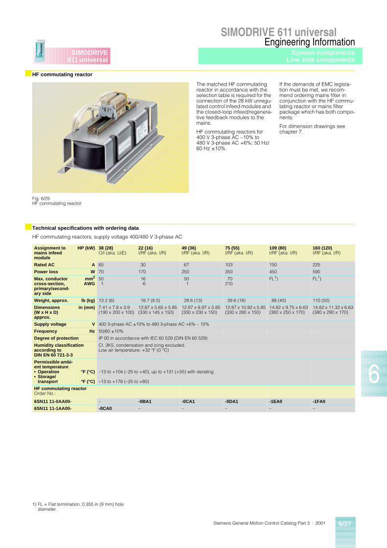
Siemens General Motion Control Catalog Part 3 · 2001 6/27
SIMODRIVE 611 universalEngineering Information
6
SIMODRIVE611 universal
■ HF commutating reactor
■ Technical specifications with ordering data
HF commutating reactors, supply voltage 400/480 V 3-phase AC
The matched HF commutating reactor in accordance with the selection table is required for the connection of the 28 kW unregu-lated control infeed modules and the closed-loop infeed/regenera-tive feedback modules to the mains.
HF commutating reactors for 400 V 3-phase AC –10% to 480 V 3-phase AC +6%; 50 Hz/60 Hz ±10%.
If the demands of EMC legisla-tion must be met, we recom-mend ordering mains filter in conjunction with the HF commu-tating reactor or mains filter package which has both compo-nents.
For dimension drawings see chapter 7.
Fig. 6/25HF commutating reactor
Assignment to mains infeed module
HP (kW) 38 (28)O/I (aka. U/E)
22 (16)I/RF (aka. I/R)
49 (36)I/RF (aka. I/R)
75 (55)I/RF (aka. I/R)
109 (80)I/RF (aka. I/R)
160 (120)I/RF (aka. I/R)
Rated AC A 65 30 67 103 150 225
Power loss W 70 170 250 350 450 590
Max. conductor cross-section, primary/second-ary side
mm2
AWG501
166
501
70210
FL1) FL1)
Weight, approx. lb (kg) 13.2 (6) 18.7 (8.5) 28.6 (13) 39.6 (18) 88 (40) 110 (50)
Dimensions (W x H x D)approx.
in (mm) 7.41 x 7.8 x 3.9(190 x 200 x 100)
12.87 x 5.65 x 5.85(330 x 145 x 150)
12.87 x 8.97 x 5.85(330 x 230 x 150)
12.87 x 10.92 x 5.85(330 x 280 x 150)
14.82 x 9.75 x 6.63(380 x 250 x 170)
14.82 x 11.32 x 6.63(380 x 290 x 170)
Supply voltage V 400 3-phase AC ±10% to 480 3-phase AC +6% – 10%
Frequency Hz 50/60 ±10%
Degree of protection IP 00 in accordance with IEC 60 529 (DIN EN 60 529)
Humidity classification according to DIN EN 60 721-3-3
Cl. 3K5, condensation and icing excluded.Low air temperature: +32 °F (0 °C)
Permissible ambi-ent temperature• Operation• Storage/
transport
°F (°C)
°F (°C)
–13 to +104 (–25 to +40), up to +131 (+55) with derating
–13 to +176 (–25 to +80)
HF commutating reactorOrder No.:
6SN11 11-0AA00- – -0BA1 -0CA1 -0DA1 -1EA0 -1FA0
6SN11 11-1AA00- -0CA0 – – – – –
1) FL = Flat termination, 0.355 in (9 mm) hole diameter.
System componentsLine side components
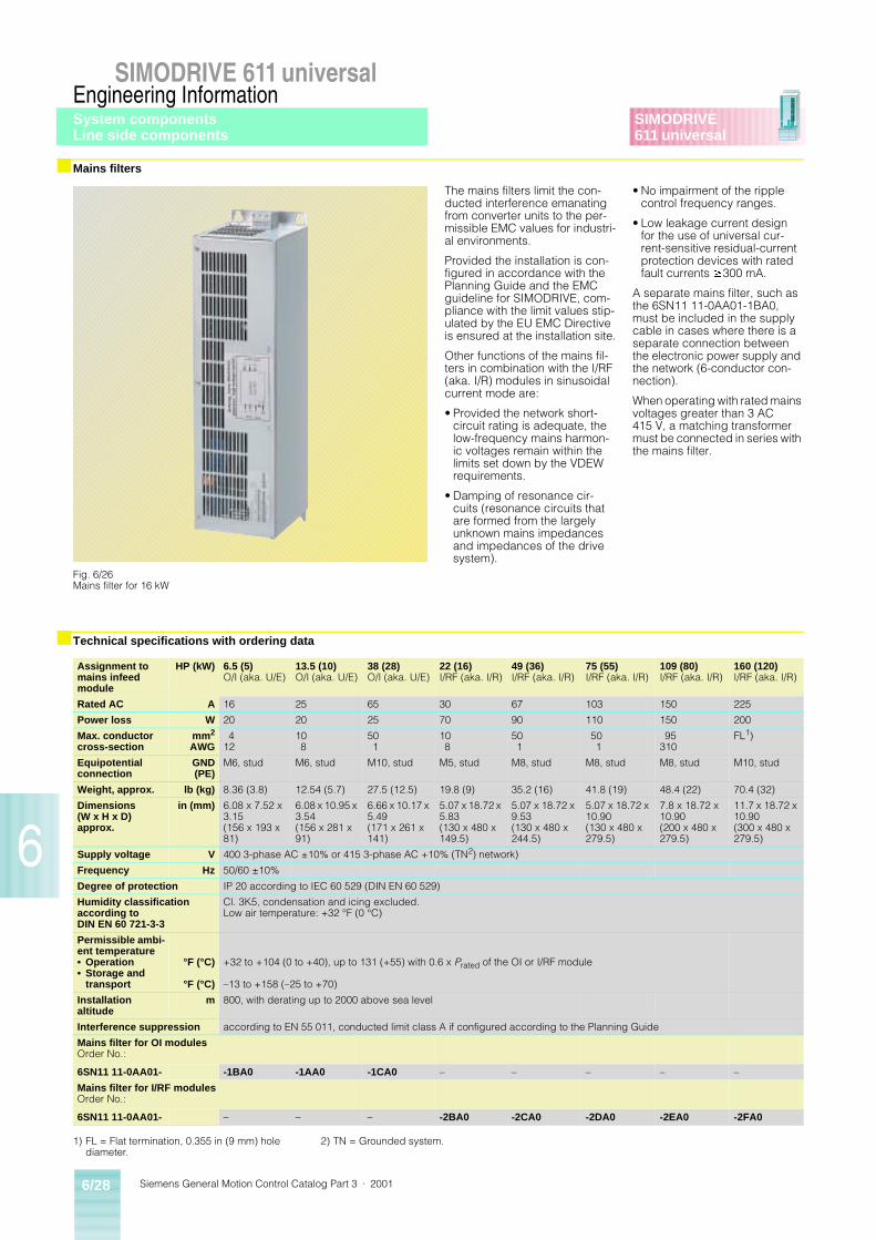
Siemens General Motion Control Catalog Part 3 · 20016/28
SIMODRIVE 611 universalEngineering Information
6
SIMODRIVE611 universal
■ Mains filters
■ Technical specifications with ordering data
The mains filters limit the con-ducted interference emanating from converter units to the per-missible EMC values for industri-al environments.
Provided the installation is con-figured in accordance with the Planning Guide and the EMC guideline for SIMODRIVE, com-pliance with the limit values stip-ulated by the EU EMC Directive is ensured at the installation site.
Other functions of the mains fil-ters in combination with the I/RF (aka. I/R) modules in sinusoidal current mode are:
• Provided the network short-circuit rating is adequate, the low-frequency mains harmon-ic voltages remain within the limits set down by the VDEW requirements.
• Damping of resonance cir-cuits (resonance circuits that are formed from the largely unknown mains impedances and impedances of the drive system).
• No impairment of the ripple control frequency ranges.
• Low leakage current design for the use of universal cur-rent-sensitive residual-current protection devices with rated fault currents ³300 mA.
A separate mains filter, such as the 6SN11 11-0AA01-1BA0, must be included in the supply cable in cases where there is a separate connection between the electronic power supply and the network (6-conductor con-nection).
When operating with rated mains voltages greater than 3 AC 415 V, a matching transformer must be connected in series with the mains filter.
Fig. 6/26Mains filter for 16 kW
Assignment to mains infeed module
HP (kW) 6.5 (5)O/I (aka. U/E)
13.5 (10)O/I (aka. U/E)
38 (28)O/I (aka. U/E)
22 (16)I/RF (aka. I/R)
49 (36)I/RF (aka. I/R)
75 (55)I/RF (aka. I/R)
109 (80)I/RF (aka. I/R)
160 (120)I/RF (aka. I/R)
Rated AC A 16 25 65 30 67 103 150 225
Power loss W 20 20 25 70 90 110 150 200
Max. conductor cross-section
mm2
AWG4
12108
501
108
501
501
95310
FL1)
Equipotential connection
GND(PE)
M6, stud M6, stud M10, stud M5, stud M8, stud M8, stud M8, stud M10, stud
Weight, approx. lb (kg) 8.36 (3.8) 12.54 (5.7) 27.5 (12.5) 19.8 (9) 35.2 (16) 41.8 (19) 48.4 (22) 70.4 (32)
Dimensions (W x H x D)approx.
in (mm) 6.08 x 7.52 x 3.15(156 x 193 x 81)
6.08 x 10.95 x 3.54 (156 x 281 x 91)
6.66 x 10.17 x 5.49 (171 x 261 x 141)
5.07 x 18.72 x 5.83 (130 x 480 x 149.5)
5.07 x 18.72 x 9.53 (130 x 480 x 244.5)
5.07 x 18.72 x 10.90 (130 x 480 x 279.5)
7.8 x 18.72 x 10.90 (200 x 480 x 279.5)
11.7 x 18.72 x 10.90 (300 x 480 x 279.5)
Supply voltage V 400 3-phase AC ±10% or 415 3-phase AC +10% (TN2) network)
Frequency Hz 50/60 ±10%
Degree of protection IP 20 according to IEC 60 529 (DIN EN 60 529)
Humidity classification according to DIN EN 60 721-3-3
Cl. 3K5, condensation and icing excluded.Low air temperature: +32 °F (0 °C)
Permissible ambi-ent temperature• Operation• Storage and
transport
°F (°C)
°F (°C)
+32 to +104 (0 to +40), up to 131 (+55) with 0.6 x Prated of the OI or I/RF module
–13 to +158 (–25 to +70)
Installation altitude
m 800, with derating up to 2000 above sea level
Interference suppression according to EN 55 011, conducted limit class A if configured according to the Planning Guide
Mains filter for OI modulesOrder No.:
6SN11 11-0AA01- -1BA0 -1AA0 -1CA0 – – – – –
Mains filter for I/RF modulesOrder No.:
6SN11 11-0AA01- – – – -2BA0 -2CA0 -2DA0 -2EA0 -2FA0
1) FL = Flat termination, 0.355 in (9 mm) hole diameter.
2) TN = Grounded system.
System componentsLine side components
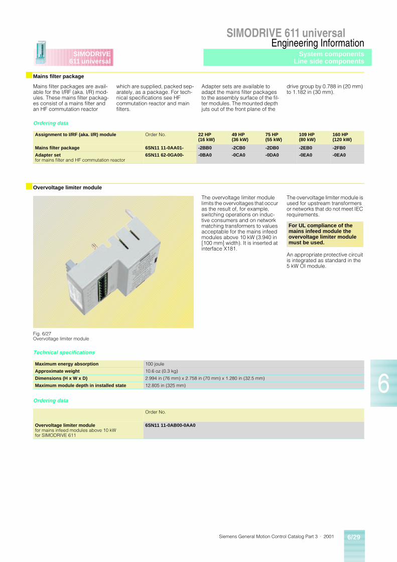
Siemens General Motion Control Catalog Part 3 · 2001 6/29
SIMODRIVE 611 universalEngineering Information
6
SIMODRIVE611 universal
■ Mains filter package
Ordering data
■ Overvoltage limiter module
Technical specifications
Ordering data
Mains filter packages are avail-able for the I/RF (aka. I/R) mod-ules. These mains filter packag-es consist of a mains filter and an HF commutation reactor
which are supplied, packed sep-arately, as a package. For tech-nical specifications see HF commutation reactor and main filters.
Adapter sets are available to adapt the mains filter packages to the assembly surface of the fil-ter modules. The mounted depth juts out of the front plane of the
drive group by 0.788 in (20 mm) to 1.182 in (30 mm).
The overvoltage limiter module limits the overvoltages that occur as the result of, for example, switching operations on induc-tive consumers and on network matching transformers to values acceptable for the mains infeed modules above 10 kW (3.940 in [100 mm] width). It is inserted at interface X181.
The overvoltage limiter module is used for upstream transformers or networks that do not meet IEC requirements.
An appropriate protective circuit is integrated as standard in the 5 kW OI module.
Assignment to I/RF (aka. I/R) module Order No. 22 HP(16 kW)
49 HP(36 kW)
75 HP(55 kW)
109 HP(80 kW)
160 HP(120 kW)
Mains filter package 6SN11 11-0AA01- -2BB0 -2CB0 -2DB0 -2EB0 -2FB0
Adapter setfor mains filter and HF commutation reactor
6SN11 62-0GA00- -0BA0 -0CA0 -0DA0 -0EA0 -0EA0
Fig. 6/27Overvoltage limiter module
For UL compliance of the mains infeed module the overvoltage limiter module must be used.
Maximum energy absorption 100 joule
Approximate weight 10.6 oz (0.3 kg)
Dimensions (H x W x D) 2.994 in (76 mm) x 2.758 in (70 mm) x 1.280 in (32.5 mm)
Maximum module depth in installed state 12.805 in (325 mm)
Order No.
Overvoltage limiter modulefor mains infeed modules above 10 kW for SIMODRIVE 611
6SN11 11-0AB00-0AA0
System componentsLine side components
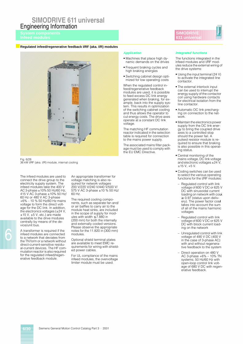
Siemens General Motion Control Catalog Part 3 · 20016/30
SIMODRIVE 611 universalEngineering Information
6
SIMODRIVE611 universal
■ Regulated infeed/regenerative feedback I/RF (aka. I/R) modules
Application
• Machines that place high dy-namic demands on the drives
• Frequent braking cycles and high braking energies
• Switching cabinet design opti-mized for low operating costs
When the regulated control in-feed/regenerative feedback modules are used, it is possible to feed excess DC link energy generated when braking, for ex-ample, back into the supply sys-tem. This results in optimization of the switching cabinet cooling and thus allows the operator to cut energy costs. The drive axes operate at a constant DC link voltage.
The matching HF commutation reactor indicated in the selection table is required for connection to the mains power supply.
The associated mains filter pack-age must be used to comply with the EU EMC Directive.
Integrated functions
The functions integrated in the infeed modules and I/RF mod-ules reduce the external wiring of the drive systems:
• Using the input terminal (24 V) to activate the integrated line contactor.
• The external interlock input can be used to interrupt the energy supply of the contactor coil using hardware contacts for electrical isolation from the line contactor.
• Automatic DC link precharg-ing on connection to the net-work.
• Maintain the electronics power supply from the DC link ener-gy to bring the coupled drive axes to a controlled stop should the power fail. A pulsed resistor module is re-quired to ensure that braking is also possible in this operat-ing status.
• Central monitoring of the mains voltage, DC link voltage and electronic voltages ±24 V, ±15 V, +5 V.
• Coding switches can be used to select the various operating functions for the I/RF modules:
– Regulated control with link voltage of 600 V DC or 625 V DC with sinusoidal current loading on network with cosl
³ 0.97 (status upon deliv-ery). The power factor cosl
takes into account the sum of all of the mains harmonic voltages
– Regulated control with link voltage of 600 V DC or 625 V DC with block current load-ing on the network
– Unregulated control with link voltage of 490 V DC (400 V in the case of 3-phase AC) with and without regenera-tive feedback to the system
– Direct operation on 480 V AC 3-phase +6% – 10% TN systems; 50 Hz/60 Hz with open-loop control link volt-age of 680 V DC with regen-erative feedback.
The infeed modules are used to connect the drive group to the electricity supply system. The infeed modules take the 400 V AC 3-phase ±10% 50 Hz/60 Hz, 415 V AC 3-phase ±10% 50 Hz/60 Hz or 480 V AC 3-phase +6% – 10 % 50 Hz/60 Hz mains voltage to form the direct volt-age for the DC link. In addition, the electronics voltages (±24 V, ±15 V, ±5 V, etc.) are made available to the drive modules centrally by means of the de-vice/unit bus.
A transformer is required if the infeed modules are connected to a network that deviates from the TN form or a network without direct-current-sensitive residu-al-current devices. The HF com-mutation reactor is also required for the regulated infeed/regen-erative feedback module.
An appropriate transformer for voltage matching is also re-quired for network voltages 200 V/220 V/240 V/440 V/500 V/575 V AC 3-phase ±10 % 50 Hz/60 Hz.
The required cooling compo-nents, such as separate fan and/or air baffles to carry air to the module heat sinks, are included in the scope of supply for mod-ules with width £7.880 in (200 mm) for both the internally and externally cooled versions. Please observe the appropriate notes for the 11.820 in (300 mm) modules.
Optional shield terminal plates are available to meet EMC re-quirements for wiring with shield-ed power cables.
For UL compliance of the mains infeed modules, the overvoltage limiter module must be used.
Fig. 6/2836 kW I/RF (aka. I/R) module, internal cooling
System componentsInfeed modules
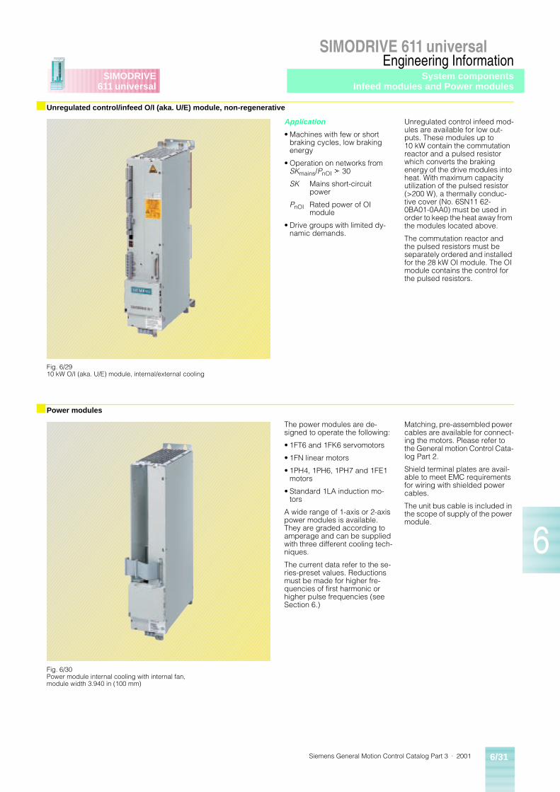
Siemens General Motion Control Catalog Part 3 · 2001 6/31
SIMODRIVE 611 universalEngineering Information
6
SIMODRIVE611 universal
■ Unregulated control/infeed O/I (aka. U/E) module, non-regenerative
■ Power modules
Application
• Machines with few or short braking cycles, low braking energy
• Operation on networks from SKmains/PnOI ³ 30
SK Mains short-circuitpower
PnOI Rated power of OI module
• Drive groups with limited dy-namic demands.
Unregulated control infeed mod-ules are available for low out-puts. These modules up to 10 kW contain the commutation reactor and a pulsed resistor which converts the braking energy of the drive modules into heat. With maximum capacity utilization of the pulsed resistor (>200 W), a thermally conduc-tive cover (No. 6SN11 62-0BA01-0AA0) must be used in order to keep the heat away from the modules located above.
The commutation reactor and the pulsed resistors must be separately ordered and installed for the 28 kW OI module. The OI module contains the control for the pulsed resistors.
The power modules are de-signed to operate the following:
• 1FT6 and 1FK6 servomotors
• 1FN linear motors
• 1PH4, 1PH6, 1PH7 and 1FE1 motors
• Standard 1LA induction mo-tors
A wide range of 1-axis or 2-axis power modules is available. They are graded according to amperage and can be supplied with three different cooling tech-niques.
The current data refer to the se-ries-preset values. Reductions must be made for higher fre-quencies of first harmonic or higher pulse frequencies (see Section 6.)
Matching, pre-assembled power cables are available for connect-ing the motors. Please refer to the General motion Control Cata-log Part 2.
Shield terminal plates are avail-able to meet EMC requirements for wiring with shielded power cables.
The unit bus cable is included in the scope of supply of the power module.
Fig. 6/2910 kW O/I (aka. U/E) module, internal/external cooling
Fig. 6/30Power module internal cooling with internal fan, module width 3.940 in (100 mm)
System componentsInfeed modules and Power modules
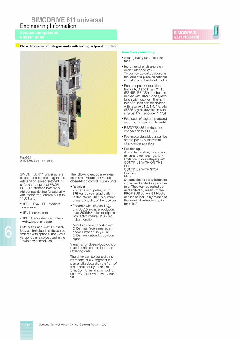
Siemens General Motion Control Catalog Part 3 · 20016/32
SIMODRIVE 611 universalEngineering Information
6
SIMODRIVE611 universal
■ Closed-loop control plug-in units with analog setpoint interface
Functions (selection)
• Analog rotary setpoint inter-face
• Incremental shaft-angle en-coder interface WSG To convey actual positions in the form of a pulse directional signal to a higher-level control
• Encoder pulse simulation, tracks A, B and R; ±5 V TTL (RS 485, RS 422) can be con-nected with 1024 signals/revo-lution with resolver. The num-ber of pulses can be divided with resolver: 1:2, 1:4, 1:8. 0 to 65535 signals/revolution with sin/cos 1 Vpp encoder 1:1 S/R
• Four each of digital inputs and outputs, user-parameterizable
• RS232/RS485 interface for connection to a PC/PG
• Four motor data blocks can be stored per axis, star/delta changeover possible
• PositioningAbsolute, relative, rotary axis, external block change, jerk limitation; block relaying with:CONTINUE WITH ON-THE-FLY,CONTINUE WITH STOP, GO TO, END64 data blocks per axis can be stored and edited as parame-ters. They can be called up and edited by means of the PROFIBUS option. 64 blocks can be called up by means of the terminal extension option for axis A.
SIMODRIVE 611 universal is a closed-loop control plug-in unit with analog speed setpoint in-terface and optional PROFI-BUS-DP interface both with/without positioning functionality with motor frequencies of up to 1400 Hz for:
• 1FT6, 1FK6, 1FE1 synchro-nous motors
• 1FN linear motors
• 1PH, 1LA5 induction motors with/without encoder
Both 1-axis and 2-axis closed-loop control plug-in units can be ordered with options. The 2-axis versions can also be used in the 1-axis power modules.
The following encoder evalua-tions are available for various closed-loop control plug-in units:
• Resolver2 to 6 pairs of poles; up to 375 Hz, pulse multiplication factor internal 4096 x number of pairs of poles of the resolver
• Encoder with sin/cos 1 Vpp0 to 65535 signals/revolution, max. 350 kHz pulse multiplica-tion factor internal 128 x sig-nals/revolution
• Absolute value encoder with EnDat interface same as en-coder sin/cos 1 Vpp plus EnDat evaluation for position signal
Variants: for closed-loop control plug-in units and options, see Ordering data.
The drive can be started either by means of a 7-segment dis-play and keyboard on the front of the module or by means of the SimoCom U installation tool run on a PC under Windows NT/95/98.
Fig. 6/31SIMODRIVE 611 universal
System componentsPlug-in units
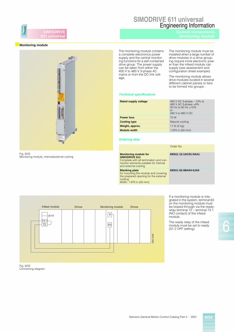
Siemens General Motion Control Catalog Part 3 · 2001 6/33
SIMODRIVE 611 universalEngineering Information
6
SIMODRIVE611 universal
■ Monitoring module
The monitoring module contains a complete electronics power supply and the central monitor-ing functions for a self-contained drive group. The power supply can be taken from either the 400 V to 480 V 3-phase AC mains or from the DC link volt-age.
The monitoring module must be installed when a large number of drive modules in a drive group-ing require more electronic pow-er than the infeed module can supply (see assessment and configuration sheet example).
The monitoring module allows drive modules located in several different cabinet panels or tiers to be formed into groups.
Technical specifications
Ordering data
If a monitoring module is inte-grated in the system, terminal 63 on the monitoring module must be looped through via the ready-relay terminal 72 – terminal 73.1 (NO contact) of the infeed module.
The ready relay of the infeed module must be set to ready (S1.2 OFF setting).
Fig. 6/32Monitoring module, internal/external cooling
Rated supply voltage 400 V AC 3-phase – 10% to 480 V AC 3-phase +6% 50 Hz to 60 Hz ±10%or490 V to 680 V DC
Power loss 70 W
Cooling type Natural cooling
Weight, approx. 11 lb (5 kg)
Module width 1.970 in (50 mm)
Order No.
Monitoring module for SIMODRIVE 611Complete with all termination and con-nection elements suitable for internal and external cooling
6SN11 12-1AC01-0AA1
Blanking platefor mounting the module and covering the prepared opening for the external coolingWidth: 1.970 in (50 mm)
6SN11 62-0BA04-0JA0
X111
73.172
9
63
GM
C-5
058
Drives Monitoring module DrivesInfeed module
Fig. 6/33Connecting diagram
System componentsMonitoring module
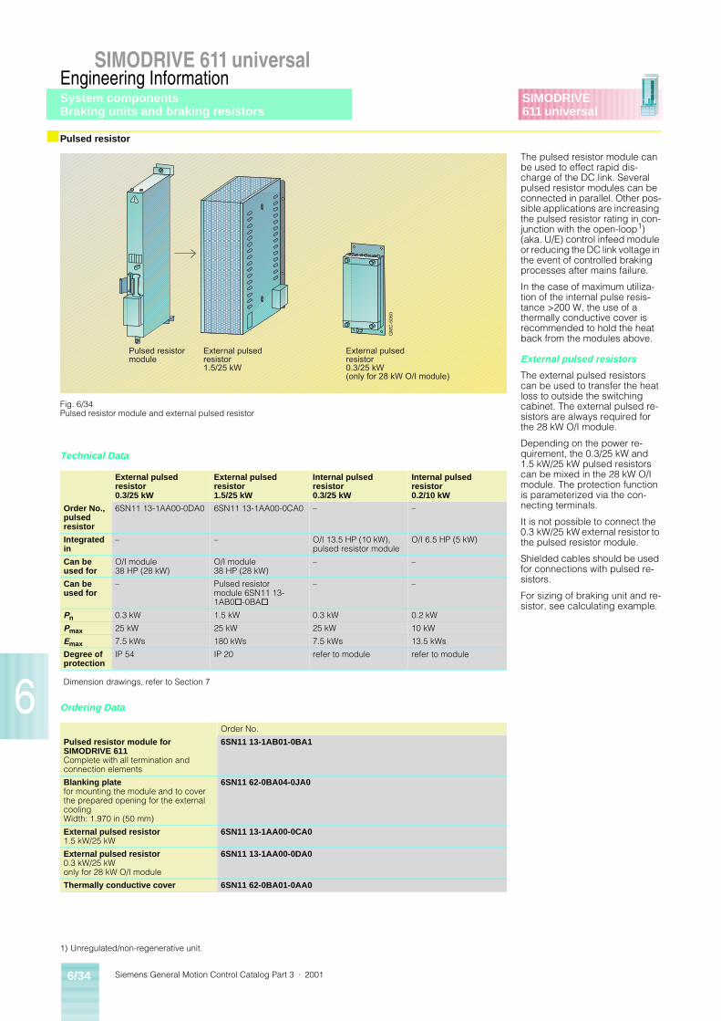
Siemens General Motion Control Catalog Part 3 · 20016/34
SIMODRIVE 611 universalEngineering Information
6
SIMODRIVE611 universal
■ Pulsed resistor
The pulsed resistor module can be used to effect rapid dis-charge of the DC link. Several pulsed resistor modules can be connected in parallel. Other pos-sible applications are increasing the pulsed resistor rating in con-junction with the open-loop1) (aka. U/E) control infeed module or reducing the DC link voltage in the event of controlled braking processes after mains failure.
In the case of maximum utiliza-tion of the internal pulse resis-tance >200 W, the use of a thermally conductive cover is recommended to hold the heat back from the modules above.
External pulsed resistors
The external pulsed resistors can be used to transfer the heat loss to outside the switching cabinet. The external pulsed re-sistors are always required for the 28 kW O/I module.
Depending on the power re-quirement, the 0.3/25 kW and 1.5 kW/25 kW pulsed resistors can be mixed in the 28 kW O/I module. The protection function is parameterized via the con-necting terminals.
It is not possible to connect the 0.3 kW/25 kW external resistor to the pulsed resistor module.
Shielded cables should be used for connections with pulsed re-sistors.
For sizing of braking unit and re-sistor, see calculating example.
Technical Data
Ordering Data
Pulsed resistormodule
External pulsedresistor1.5/25 kW
External pulsedresistor0.3/25 kW(only for 28 kW O/I module)
GM
C-5
060
Fig. 6/34Pulsed resistor module and external pulsed resistor
External pulsed resistor 0.3/25 kW
External pulsed resistor 1.5/25 kW
Internal pulsed resistor 0.3/25 kW
Internal pulsed resistor 0.2/10 kW
Order No.,pulsed resistor
6SN11 13-1AA00-0DA0 6SN11 13-1AA00-0CA0 – –
Integrated in
– – O/I 13.5 HP (10 kW), pulsed resistor module
O/I 6.5 HP (5 kW)
Can be used for
O/I module 38 HP (28 kW)
O/I module 38 HP (28 kW)
– –
Can be used for
– Pulsed resistor module 6SN11 13-1AB0@-0BA@
– –
Pn 0.3 kW 1.5 kW 0.3 kW 0.2 kW
Pmax 25 kW 25 kW 25 kW 10 kW
Emax 7.5 kWs 180 kWs 7.5 kWs 13.5 kWs
Degree of protection
IP 54 IP 20 refer to module refer to module
Dimension drawings, refer to Section 7
Order No.
Pulsed resistor module for SIMODRIVE 611Complete with all termination and connection elements
6SN11 13-1AB01-0BA1
Blanking platefor mounting the module and to cover the prepared opening for the external coolingWidth: 1.970 in (50 mm)
6SN11 62-0BA04-0JA0
External pulsed resistor1.5 kW/25 kW
6SN11 13-1AA00-0CA0
External pulsed resistor0.3 kW/25 kWonly for 28 kW O/I module
6SN11 13-1AA00-0DA0
Thermally conductive cover 6SN11 62-0BA01-0AA0
1) Unregulated/non-regenerative unit.
System componentsBraking units and braking resistors
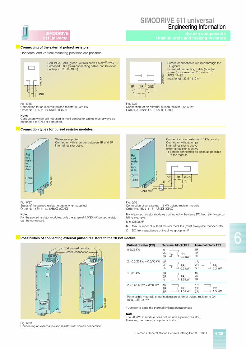
Siemens General Motion Control Catalog Part 3 · 2001 6/35
SIMODRIVE 611 universalEngineering Information
6
SIMODRIVE611 universal
■ Connecting of the external pulsed resistors
Horizontal and vertical mounting positions are possible
■ Connection types for pulsed resistor modules
■ Possibilities of connecting external pulsed resistors to the 28 kW module
Note:Conductors which are not used in multi-conductor cables must always be connected to GND at both ends.
Note:For the pulsed resistor modules, only the external 1.5/25 kW pulsed resistor can be connected.
No. of pulsed resistor modules connected to the same DC link, refer to calcu-lating example.
N £ C/500 mF
N Max. number of pulsed resistor modules (must always be rounded-off)
C DC link capacitance of the drive group in mF
GND
GM
C-5
061
Fig. 6/35Connection for an external pulsed resistor 0.3/25 kWOrder No.: 6SN11 13-1AA00-0DA00
Red, blue, GND (green, yellow) each 1.5 mm2/AWG 16Screened 9.8 ft (3 m) connecting cable, can be exten-ded up to 32.8 ft (10 m)
3R 1R GND
GM
C-5
062
Fig. 6/36Connection for an external pulsed resistor 1.5/25 kWOrder No.: 6SN11 13-1AA00-0CA00
Screen connection is realized through the PG gland Screened connecting cable (braided screen) cross-section 2.5 – 4 mm2/AWG 14–12max. length 32.8 ft (10 m)
1R2R
3R
P600
M600
GM
C-5
063
Pul-sedresis-tormo-dule
Fig. 6/37Status of the pulsed resistor module when suppliedOrder No.: 6SN11 13-1AB0@-0@A@
Status as supplied:Connector with a jumper between 1R and 2Rinternal resistor active
Pul-sedresis-tormo-dule
GND rail
GM
C-5
064
1R2R
3R
P600
M6003R 1R GND
1)
Fig. 6/38Connection of an external 1.5 kW pulsed resistor moduleOrder No.: 6SN11 13-1AB0@-0@A@
Connection of an external 1.5 kW resistor:Connector without jumper internal resistor is activeexternal resistor is active1) Screen connection as close as possible
to the module
GM
C-5
065
Ext. pulsed resistorScreen connection
Fig. 6/39Connecting an external pulsed resistor with screen connection
Pulsed resistor (PR) Terminal block TR1 Terminal block TR2
0.3/25 kW 1R2R3R
2 x 0.3/25 kW = 0.6/50 kW
1.5/25 kW 1R2R3R
2 x 1.5/25 kW = 3/50 kW
Permissible methods of connecting an external pulsed resistor to O/I (aka. U/E) 28 kW
PR0.3 kW
*
1R2R3R
PR0.3 kW
*
1R2R3R
PR0.3 kW
*
1R2R3R
PR1.5 kW
1R2R3R
PR1.5 kW
1R2R3R
PR1.5 kW
1R2R3R
* Jumper to code the thermal limiting characteristic
Note:The 28 kW O/I module does not include a pulsed resistor. However, the braking chopper is built in.
System componentsBraking units and braking resistors
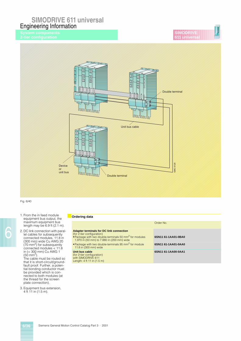
Siemens General Motion Control Catalog Part 3 · 20016/36
SIMODRIVE 611 universalEngineering Information
6
SIMODRIVE611 universal
1. From the in feed module equipment bus output, the maximum equipment bus length may be 6.9 ft (2.1 m).
2. DC link connection with paral-lel cables for subsequently connected modules, 11.8 in (300 mm) wide Cu AWG 20 (70 mm2) for subsequently connected modules < 11.8 in (< 300 mm) Cu AWG 1 (50 mm2).The cable must be routed so that it is short-circuit/ground-fault proof. Further, a poten-tial bonding conductor must be provided which is con-nected to both modules (at the thread for the screen plate connection).
3. Equipment bus extension, 4 ft 11 in (1.5 m).
■ Ordering data
GM
C-5
126
Double terminal
Unit bus cable
Double terminal
Deviceorunit bus
Fig. 6/40
Order No.
Adapter terminals for DC link connection(for 2-tier configuration)•Package with two double-terminals 50 mm2 for modules
1.970 in (50 mm) to 7.880 in (200 mm) wide6SN11 61-1AA01-0BA0
•Package with two double-terminals 95 mm2 for module 11.8 in (300 mm) wide
6SN11 61-1AA01-0AA0
Unit bus cable(for 2-tier configuration)with SIMODRIVE 611Length: 4 ft 11 in (1.5 m)
6SN11 61-1AA00-0AA1
System components2-tier configuration
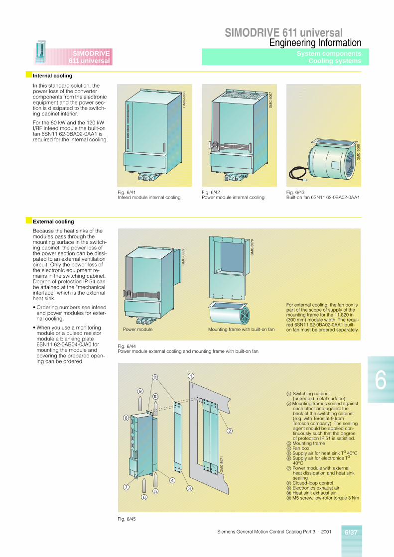
Siemens General Motion Control Catalog Part 3 · 2001 6/37
SIMODRIVE 611 universalEngineering Information
6
SIMODRIVE611 universal
■ Internal cooling
■ External cooling
In this standard solution, the power loss of the converter components from the electronic equipment and the power sec-tion is dissipated to the switch-ing cabinet interior.
For the 80 kW and the 120 kW I/RF infeed module the built-on fan 6SN11 62-0BA02-0AA1 is required for the internal cooling.
Because the heat sinks of the modules pass through the mounting surface in the switch-ing cabinet, the power loss of the power section can be dissi-pated to an external ventilation circuit. Only the power loss of the electronic equipment re-mains in the switching cabinet. Degree of protection IP 54 can be attained at the “mechanical interface” which is the external heat sink.
• Ordering numbers see infeed and power modules for exter-nal cooling.
• When you use a monitoring module or a pulsed resistor module a blanking plate 6SN11 62-0AB04-0JA0 for mounting the module and covering the prepared open-ing can be ordered.
GM
C-5
066
Fig. 6/41Infeed module internal cooling
Fig. 6/42Power module internal cooling
Fig. 6/43Built-on fan 6SN11 62-0BA02-0AA1
GM
C-5
067
GM
C-5
068
GM
C-5
069
GM
C-5
070
Fig. 6/44Power module external cooling and mounting frame with built-on fan
Power module Mounting frame with built-on fan
For external cooling, the fan box is part of the scope of supply of the mounting frame for the 11.820 in (300 mm) module width. The requi-red 6SN11 62-0BA02-0AA1 built-on fan must be ordered separately.
Fig. 6/45
$ Switching cabinet (untreated metal surface)
% Mounting frames sealed against each other and against the back of the switching cabinet (e.g. with Terostat-9 from Teroson company). The sealing agent should be applied con-tinuously such that the degree of protection IP 51 is satisfied.
& Mounting frame( Fan box) Supply air for heat sink T3 40°C* Supply air for electronics T3
40°C+ Power module with external
heat dissipation and heat sink sealing
, Closed-loop control- Electronics exhaust air. Heat sink exhaust air/ M5 screw, low-rotor torque 3 Nm
11
9
8
7
65
4
3
2
1
10
GM
C-5
071
System componentsCooling systems
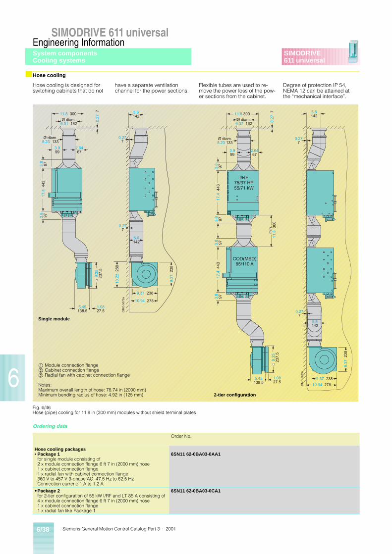
Siemens General Motion Control Catalog Part 3 · 20016/38
SIMODRIVE 611 universalEngineering Information
6
SIMODRIVE611 universal
■ Hose cooling
Ordering data
Hose cooling is designed for switching cabinets that do not
have a separate ventilation channel for the power sections.
Flexible tubes are used to re-move the power loss of the pow-er sections from the cabinet.
Degree of protection IP 54, NEMA 12 can be attained at the “mechanical interface”.
5.6142
GM
C-5
072a
Ø diam.6.31 162
2.6467
Ø diam.5.23 133
3.999
17.4
443
3.8
97
11.8 300
0.27
7
5.45138.5
1.0827.5
5.6142
0.277
0.277
9.37
238
9.37 238
10.94 278
10.2
3 2
60
3.8
97
9.35
237.
5
GM
C-5
073a
Ø diam.6.37 162
2.6467
Ø diam.5.23 133
3.999
3.8
9717
.4 4
43
11.8 300
min
.11
.8 3
009.
3523
7.5
5.45138.5
1.0827.5
5.6142
0.277
0.27
7
5.6142
0.277
9.37 238
10.94 278
I/RF75/97 HP55/71 kW
COD(MSD)85/110 A
3.8
973.
897
3.8
9717
.4 4
43
9.37
238
Fig. 6/46Hose (pipe) cooling for 11.8 in (300 mm) modules without shield terminal plates
Single module
$ Module connection flange% Cabinet connection flange& Radial fan with cabinet connection flange
Notes:Maximum overall length of hose: 78.74 in (2000 mm)Minimum bending radius of hose: 4.92 in (125 mm) 2-tier configuration
Order No.
Hose cooling packages• Package 1
for single module consisting of2 x module connection flange 6 ft 7 in (2000 mm) hose1 x cabinet connection flange1 x radial fan with cabinet connection flange360 V to 457 V 3-phase AC; 47.5 Hz to 62.5 HzConnection current: 1 A to 1.2 A
6SN11 62-0BA03-0AA1
•Package 2for 2-tier configuration of 55 kW I/RF and LT 85 A consisting of4 x module connection flange 6 ft 7 in (2000 mm) hose1 x cabinet connection flange1 x radial fan like Package 1
6SN11 62-0BA03-0CA1
System componentsCooling systems
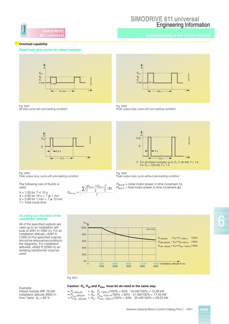
Siemens General Motion Control Catalog Part 3 · 2001 6/39
SIMODRIVE 611 universalEngineering Information
6
SIMODRIVE611 universal Dimensioning of the infeed module
■ Overload capability
Rated load duty cycles for infeed modules
The following rule of thumb is valid:
X = 1.03 for T £ 10 sX = 0.90 for 10 s < T £ 1 minX = 0.89 for 1 min < T £ 10 minT = Total cycle time
PMot B = initial motor power in time increment DtiPMot E = final motor power in time increment Dti
De-rating as a function of the installation altitude
All of the specified outputs are valid up to an installation alti-tude of 3281 ft (1000 m). For an installation altitude >3281 ft (1000 m) the specified outputs should be reduced according to the diagrams. For installation altitudes >6562 ft (2000 m) an isolating transformer must be used.
Example:Infeed module I/RF 16 kW;installation altitude 2000 m:from Table: XH = 83 %
Caution: Pn, Ps6 and Pmax. must be de-rated in the same way.
® Pn altitude = XH · Pn 1000 m/100% = 83% · 16 kW/100% = 13.28 kW® Pns6 altitude = XH · Pns6 1000 m/100% = 83% · 21 kW/100% = 17.43 kW® Pmax. altitude = XH · Pmax. 1000 m/100% = 83% · 35 kW/100% = 29.05 kW
GM
C-5
01
6
P
Pmax
t10 min
4 min
Ps6
PnPn0.4
Fig. 6/47S6 duty cycle with pre-loading condition
GM
C-5
01
7
P
Pmax
t60 s
10 s
Ps6
PnPn0.4
Fig. 6/48Peak output duty cycle with pre-loading condition
GM
C-5
01
8
0.2 s
PPmax
Pn
t10 s
Fig. 6/49Peak output duty cycle with pre-loading condition
GM
C-5
01
9
4 s
PF P
Pn
t10 s
n
Fig. 6/50Peak output duty cycle without pre-loading condition
F: For all infeed modules up to Pn £ 80 kW, F = 1.6For Pn = 120 kW, F = 1.4
P
P Pt
TMot rms
Mot B Mot Ei2>
+
⋅∑2
∆
32811000
0 65622000
98433000
131244000
164055000
0%
20%
40%
60%
80%
100%
Installation altitude ft (m)
Pn altitude = XH Pn 1000 m /100%
PnS6 altitude = XH Ps6 1000 m /100%
Pmax. altitude = XH Pmax. 1000 m /100%
XH
GMC-5020b
Fig. 6/51
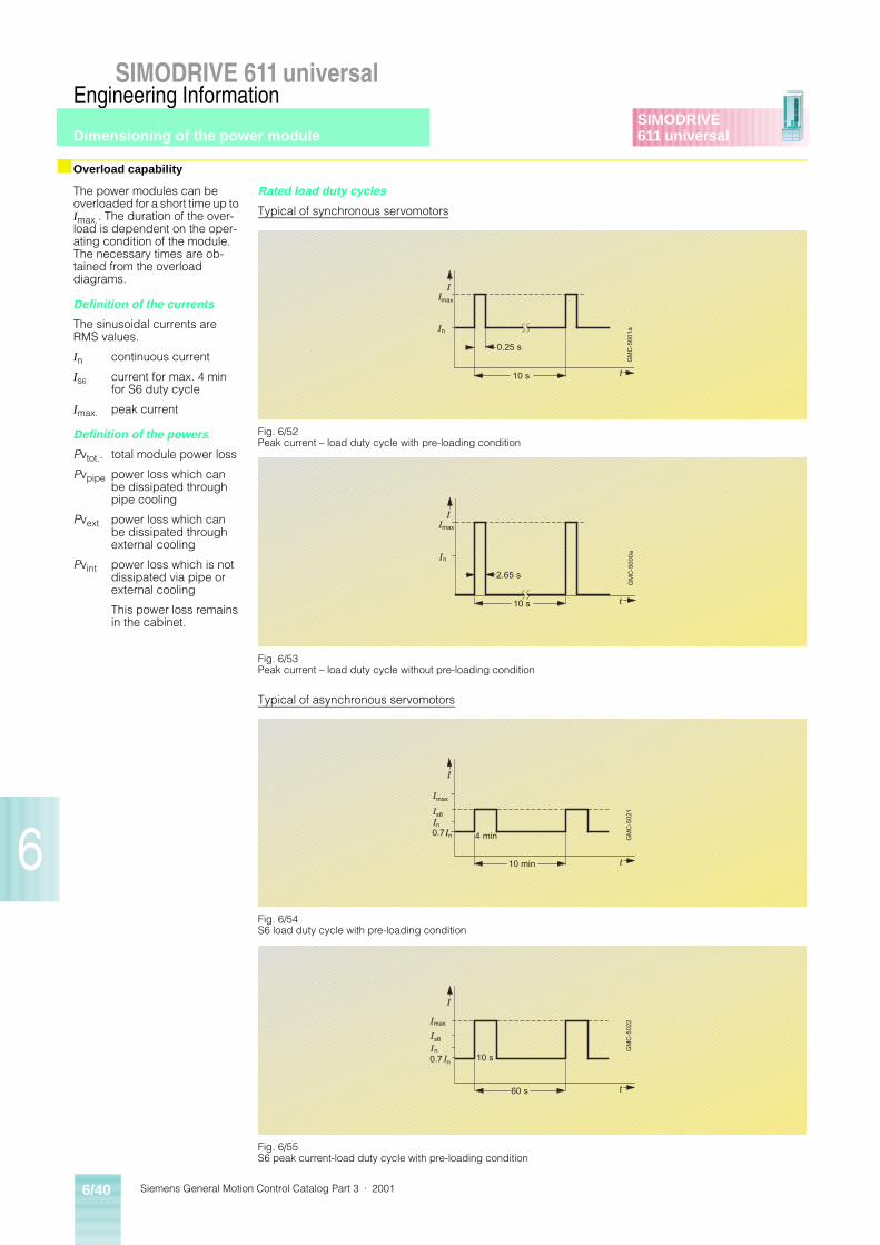
Siemens General Motion Control Catalog Part 3 · 20016/40
SIMODRIVE 611 universalEngineering Information
6
SIMODRIVE611 universal
■ Overload capability
The power modules can be overloaded for a short time up to Imax.. The duration of the over-load is dependent on the oper-ating condition of the module. The necessary times are ob-tained from the overload diagrams.
Definition of the currents
The sinusoidal currents are RMS values.
In continuous current
Is6 current for max. 4 min for S6 duty cycle
Imax. peak current
Definition of the powers
Pvtot.. total module power loss
Pvpipe power loss which can be dissipated through pipe cooling
Pvext power loss which can be dissipated through external cooling
Pvint power loss which is not dissipated via pipe or external cooling
This power loss remains in the cabinet.
Rated load duty cycles
Typical of synchronous servomotors
Typical of asynchronous servomotors
GM
C-5
00
1a
0.25 s
IImax
In
t10 s
Fig. 6/52Peak current – load duty cycle with pre-loading condition
GM
C-5
00
0a
2.65 s
IImax
In
t10 s
Fig. 6/53Peak current – load duty cycle without pre-loading condition
GM
C-5
02
1
I
Imax
t10 min
4 min
Is6In
In0.7
Fig. 6/54S6 load duty cycle with pre-loading condition
GM
C-5
02
2
I
Imax
n
t60 s
10 s
Is6
IIn0.7
Fig. 6/55S6 peak current-load duty cycle with pre-loading condition
Dimensioning of the power module
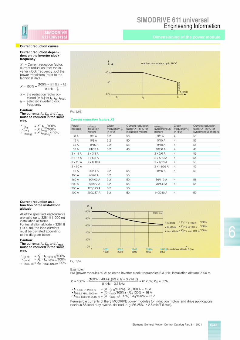
Siemens General Motion Control Catalog Part 3 · 2001 6/41
SIMODRIVE 611 universalEngineering Information
6
SIMODRIVE611 universal
■ Current reduction curves
Current reduction depen-dent on the inverter clock frequency
X1 = Current reduction factor, current reduction from the in-verter clock frequency f0 of the power transistors (refer to the technical data).
X = the reduction factor ob-tained [in %] for In, Is6, Imax.
fT = selected inverter clock frequency
Caution: The currents In, Is6 and Imax. must be reduced in the same way.
® InfT = X · Inf0
/100%® Is6fT
= X· Is6f0/100%
® Imax.fT = X· Imax.f0
/100%
Current reduction factors X1
Current reduction as a function of the installation altitude
All of the specified load currents are valid up to 3281 ft (1000 m) installation altitudes. For installation altitude > 3281 ft (1000 m), the load currents must be de-rated according to the diagram below.
Caution: The currents In, Is6 and Imax. must be reduced in the same way.
® In alt. = XH · In 1000 m/100%® Is6 alt. = XH · Is6 1000 m/100%® Imax. alt.= XH · Imax.1000m/100%
Example: PM (power module) 50 A: selected inverter clock frequencies 6.3 kHz; installation altitude 2000 m.
® In 6.3 kHz, 2000 m = (X · In f0/100%) · XH/100% = 12 A® IS6 6.3 kHz, 2000 m = (X · Is6 f0/100%) · XH/100% = 16 A® Imax. 6.3 kHz, 2000 m = (X · Imax. f0/100%) · XH/100% = 16 A
Permissible currents of the SIMODRIVE power modules for induction motors and drive applications (various S6 load duty cycles, defined, e.g. S6-25% ® 2.5 min/7.5 min).
XX f f
f= − − ⋅ −
100%100% 1
8( ) ( )T 0
0 kHz – GM
C-5
02
3
[kHz]
8
100
f0
Ambient temperature up to 40 °CII
00 %
%
n
f1
X1
Fig. 6/56
Power module
In/Imax induction motors
Clock frequency f0 in kHz
Current reduction factor X1 in % for induction motors
In/Imax synchronous motors
Clock frequency f0 in kHz
Current reduction factor X1 in % for synchronous motors
8 A 3/3 A 3.2 50 3/6 A 4 55
15 A 5/8 A 3.2 50 5/10 A 4 55
25 A 8/16 A 3.2 55 9/18 A 4 55
50 A 24/32 A 3.2 40 18/36 A 4 40
2 x 8 A 2 x 3/3 A 2 x 3/6 A 4 55
2 x 15 A 2 x 5/8 A 2 x 5/10 A 4 55
2 x 25 A 2 x 8/16 A 2 x 9/18 A 4 55
2 x 50 A 2 x 18/36 A 4 40
80 A 30/51 A 3.2 55 28/56 A 4 50
108 A 46/76 A 3.2 55
160 A 60/102 A 3.2 50 56/112 A 4 55
200 A 85/127 A 3.2 55 70/140 A 4 55
300 A 120/193 A 3.2 50
400 A 200/257 A 3.2 50 140/210 A 4 50
32811000
0 65622000
98433000
131244000
164055000
0%
20%
40%
60%
80%
100%
Installation altitude ft (m)
n altitude = XH n 1000 m /100%
S6 altitude = XH s6 1000 m /100%
max. altitude = XH max. 1000 m /100%
XH
GMC-5134a
I
I
I
I
I
I
Fig. 6/57
X X= − − ⋅ = =100%100% 40%) 63
8 36125%; 83%
( ( . ).
kHz – 3.2 kHz kHz – .2 kHz H
Dimensioning of the power module
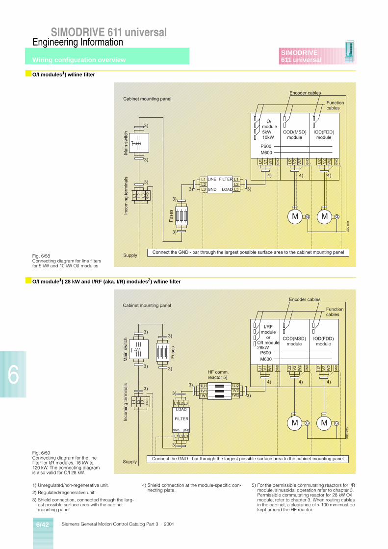
Siemens General Motion Control Catalog Part 3 · 20016/42
SIMODRIVE 611 universalEngineering Information
6
SIMODRIVE611 universal
■ O/I modules1) w/line filter
■ O/I module1) 28 kW and I/RF (aka. I/R) modules2) w/line filter
Fig. 6/58Connecting diagram for line filters for 5 kW and 10 kW O/I modules
G GM M
GM
C-5
024
U1
V1
W1
GN
D
U2
V2
W2
GN
D
U2
V2
W2
GN
D
L1 L2 L3 GN
D
M600
O/Imodule
COD(MSD)module
IOD(FDD)module
Encoder cables
Functioncables
Connect the GND - bar through the largest possible surface area to the cabinet mounting panel
Cabinet mounting panel
Inco
min
g te
rmin
als
Ma
in s
witc
h
Supply
3)
3)
3)
3)
3)
Fu
ses
4)4)4)
P600
5kW10kW
L1L2L3 GND 3)
L1L2L33)
LINE FILTER
LOAD
Fig. 6/59Connecting diagram for the line filter for I/R modules, 16 kW to 120 kW. The connecting diagram is also valid for O/I 28 kW.
G GM M
GM
C-5
025
L1 L2 L3 GN
D
W1
GN
D
U2
V2
W2
GN
D
U2
V2
W2
GN
D
M600
I/RFmodule
orO/I module
COD(MSD)module
IOD(FDD)module
Encoder cables
Functioncables
Connect the GND - bar through the largest possible surface area to the cabinet mounting panel
Cabinet mounting panel
Inco
min
g te
rmin
als
Ma
in s
witc
h
Supply
3)
4)4)4)
P600
GND
3)
3)
3)
L1L2L3
L1L2L3
1W1 1W2
LOAD
FILTER
LINE
U1
V1
3)
3) 3)
3)
Fu
ses 28kW
1U1 1U21V1 1V2
3)
HF comm.reactor 5)
1) Unregulated/non-regenerative unit.
2) Regulated/regenerative unit.
3) Shield connection, connected through the larg-est possible surface area with the cabinet mounting panel.
4) Shield connection at the module-specific con-necting plate.
5) For the permissible commutating reactors for I/R module, sinusoidal operation refer to chapter 3. Permissible commutating reactor for 28 kW O/I module, refer to chapter 3. When routing cables in the cabinet, a clearance of > 100 mm must be kept around the HF reactor.
Wiring configuration overview
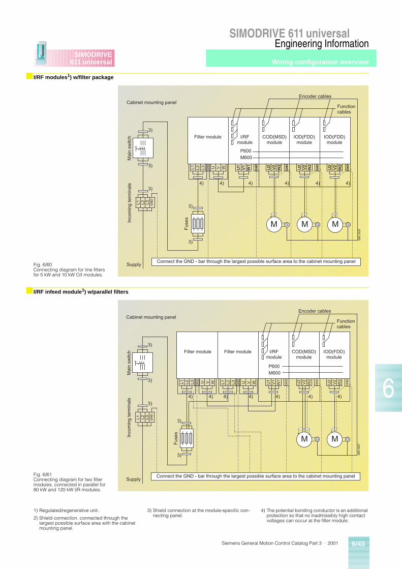
Siemens General Motion Control Catalog Part 3 · 2001 6/43
SIMODRIVE 611 universalEngineering Information
6
SIMODRIVE611 universal
■ I/RF modules1) w/filter package
■ I/RF infeed module1) w/parallel filters
Fig. 6/60Connecting diagram for line filters for 5 kW and 10 kW O/I modules.
U1
V1
W1
GN
D
U2
V2
W2
GN
D
U2
V2
W2
GN
D
U2
V2
W2
GN
D
G G GM M M
GM
C-5
026
L1 L2 L3 GN
D
U1
V1
W1
GN
D
U2
V2
W2
GN
D
U2
V2
W2
GN
D
U2
V2
W2
GN
D
M600
COD(MSD)module
I/RFmodule
IOD(FDD)module
IOD(FDD)module
Encoder cables
V W
Functioncables
Connect the GND - bar through the largest possible surface area to the cabinet mounting panel
Cabinet mounting panel
Inco
min
g te
rmin
als
Ma
in s
witc
h
Supply
3)
3)
3)
3)
3)
Fu
ses
4) 4) 4) 4)4)4)
L1 L2 L3 GN
D
U
P600
Filter module
Fig. 6/61Connecting diagram for two filter modules, connected in parallel for 80 kW and 120 kW I/R modules.
G GM M
GM
C-5
027
L1 L2 L3 GN
D
U1
V1
W1
GN
D
U2
V2
W2
GN
D
U2
V2
W2
GN
D
M600
I/RFmodule
COD(MSD)module
IOD(FDD)module
Encoder cables
V W
Functioncables
Connect the GND - bar through the largest possible surface area to the cabinet mounting panel
Cabinet mounting panel
Inco
min
g te
rmin
als
Ma
in s
witc
h
Supply
3)
3)
3)
3)
3)
Fu
ses
4) 4) 4) 4)4)4)
L1 L2 L3 GN
D
U
P600
Filter module
V WL1 L2 L3 GN
D
U
4)
Filter module
1) Regulated/regenerative unit.
2) Shield connection, connected through the largest possible surface area with the cabinet mounting panel.
3) Shield connection at the module-specific con-necting panel.
4) The potential bonding conductor is an additional protection so that no inadmissibly high contact voltages can occur at the filter module.
Wiring configuration overview
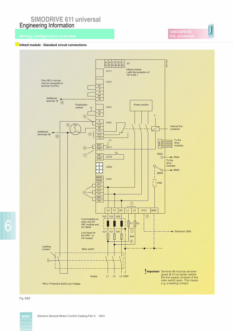
Siemens General Motion Control Catalog Part 3 · 20016/44
SIMODRIVE 611 universalEngineering Information
6
SIMODRIVE611 universal
■ Infeed module · Standard circuit connections
U1
GM
C-5
02
8
V1 W1 L1 L2 X131 GND
X171
X172
1U2 1V2 1W2
F1 F2
1U1 1V1 1W1
S1.
6
S1.
5
S1.
4
S1.
3S
1.2
S1.
1
S1
X111
X121
X141
X161
LEDs
X181
63
9 9
64
19
15
R
9
11248
111
213113
NS1
NS2
AS1
AS2
M500
P500
2U11U1
2V1
1V1
2W11W1
L-
X35
1
P600P600
M600M600
100k
L+
4
6
4
7
4
1
5
8
8
L1 L2 L3 GND
1
3
and
2
Only PELV circuitsmay be connected toterminal 19 (FR-).
Additionalterminal 19
Pushbuttoncontact
Additionalterminals 48
Leadingcontact
Supply
Power section
Internal linecontactor
To thedrivemodules
To thedrivemodules
Electronic GND
Main switch
Commutating re-actor only forI/RF module andO/I 28kW
Line fuses for the I/RF - orO/I module
PELV: Protective Earth Low Voltage
Infeed module( with the exception of O/I 5 kW )
Fig. 6/62
!Important Terminal 48 must be de-ener-gized ³10 ms earlier, before the line supply contacts of the main switch open. This means e.g. a leading contact.
Wiring configuration overview
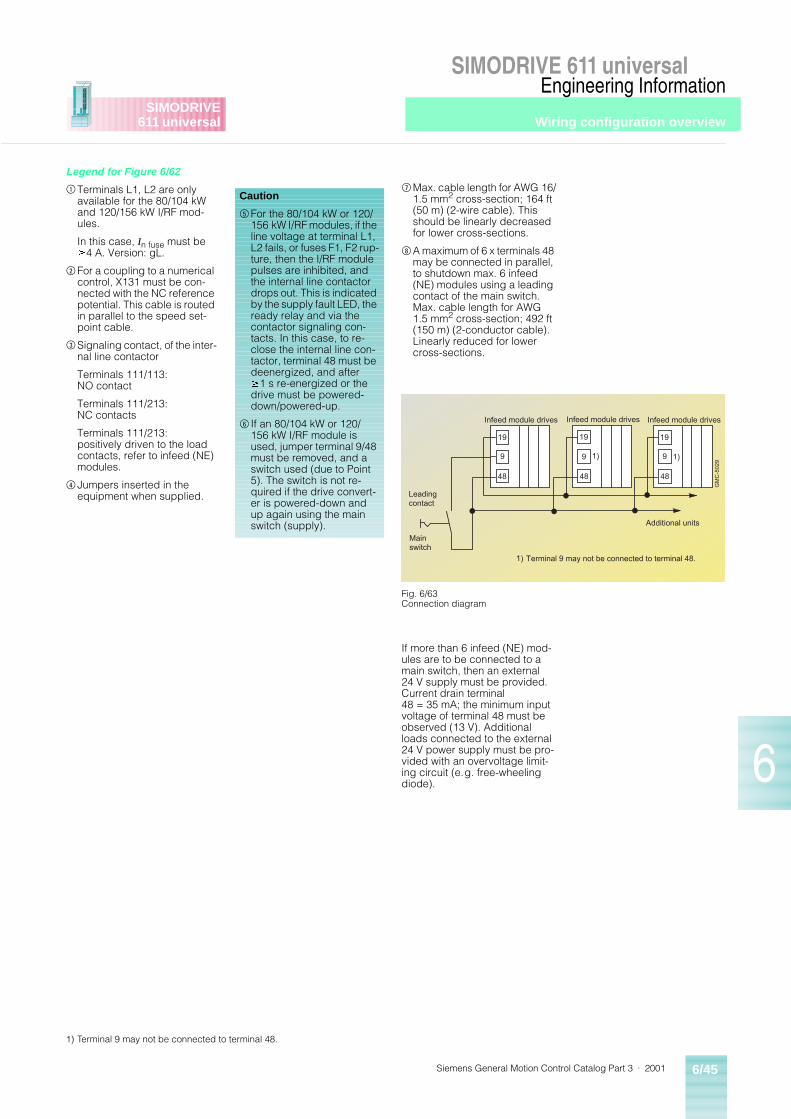
Siemens General Motion Control Catalog Part 3 · 2001 6/45
SIMODRIVE 611 universalEngineering Information
6
SIMODRIVE611 universal
Legend for Figure 6/62
$Terminals L1, L2 are only available for the 80/104 kW and 120/156 kW I/RF mod-ules.
In this case, In fuse must be ³4 A. Version: gL.
%For a coupling to a numerical control, X131 must be con-nected with the NC reference potential. This cable is routed in parallel to the speed set-point cable.
&Signaling contact, of the inter-nal line contactor
Terminals 111/113:NO contact
Terminals 111/213:NC contacts
Terminals 111/213:positively driven to the load contacts, refer to infeed (NE) modules.
( Jumpers inserted in the equipment when supplied.
+Max. cable length for AWG 16/1.5 mm2 cross-section; 164 ft (50 m) (2-wire cable). This should be linearly decreased for lower cross-sections.
,A maximum of 6 x terminals 48 may be connected in parallel, to shutdown max. 6 infeed (NE) modules using a leading contact of the main switch. Max. cable length for AWG 1.5 mm2 cross-section; 492 ft (150 m) (2-conductor cable). Linearly reduced for lower cross-sections.
If more than 6 infeed (NE) mod-ules are to be connected to a main switch, then an external 24 V supply must be provided. Current drain terminal 48 = 35 mA; the minimum input voltage of terminal 48 must be observed (13 V). Additional loads connected to the external 24 V power supply must be pro-vided with an overvoltage limit-ing circuit (e.g. free-wheeling diode).
Caution
)For the 80/104 kW or 120/156 kW I/RF modules, if the line voltage at terminal L1, L2 fails, or fuses F1, F2 rup-ture, then the I/RF module pulses are inhibited, and the internal line contactor drops out. This is indicated by the supply fault LED, the ready relay and via the contactor signaling con-tacts. In this case, to re-close the internal line con-tactor, terminal 48 must be deenergized, and after ³1 s re-energized or the drive must be powered-down/powered-up.
* If an 80/104 kW or 120/156 kW I/RF module is used, jumper terminal 9/48 must be removed, and a switch used (due to Point 5). The switch is not re-quired if the drive convert-er is powered-down and up again using the main switch (supply).
19
1
19
9
48
19
9 9
48 48
Mainswitch
Leadingcontact
GM
C-5
029
Additional units
Infeed module drives Infeed module drivesInfeed module drives
1) 1)
1) Terminal 9 may not be connected to terminal 48.
Fig. 6/63Connection diagram
1) Terminal 9 may not be connected to terminal 48.
Wiring configuration overview
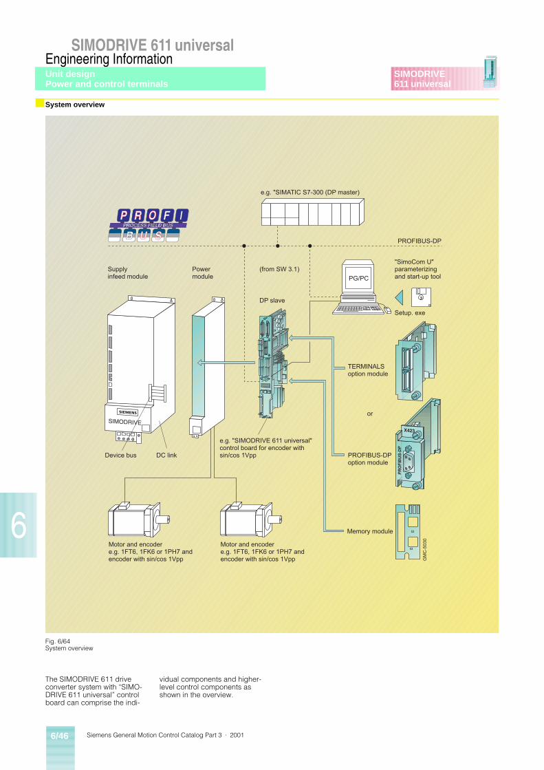
Siemens General Motion Control Catalog Part 3 · 20016/46
SIMODRIVE 611 universalEngineering Information
6
SIMODRIVE611 universal
■ System overview
The SIMODRIVE 611 drive converter system with “SIMO-DRIVE 611 universal” control board can comprise the indi-
vidual components and higher-level control components as shown in the overview.
GM
C-5
030
Device bus DC link
Motor and encodere.g. 1FT6, 1FK6 or 1PH7 andencoder with sin/cos 1Vpp
Motor and encodere.g. 1FT6, 1FK6 or 1PH7 andencoder with sin/cos 1Vpp
Memory module
e.g. "SIMODRIVE 611 universal"control board for encoder withsin/cos 1Vpp
TERMINALSoption module
PROFIBUS-DPoption module
or
Supplyinfeed module
Powermodule
(from SW 3.1)
DP slave
"SimoCom U"parameterizingand start-up tool
Setup. exe
e.g. "SIMATIC S7-300 (DP master)
PROFIBUS-DP
PG/PC
Fig. 6/64System overview
Unit designPower and control terminals
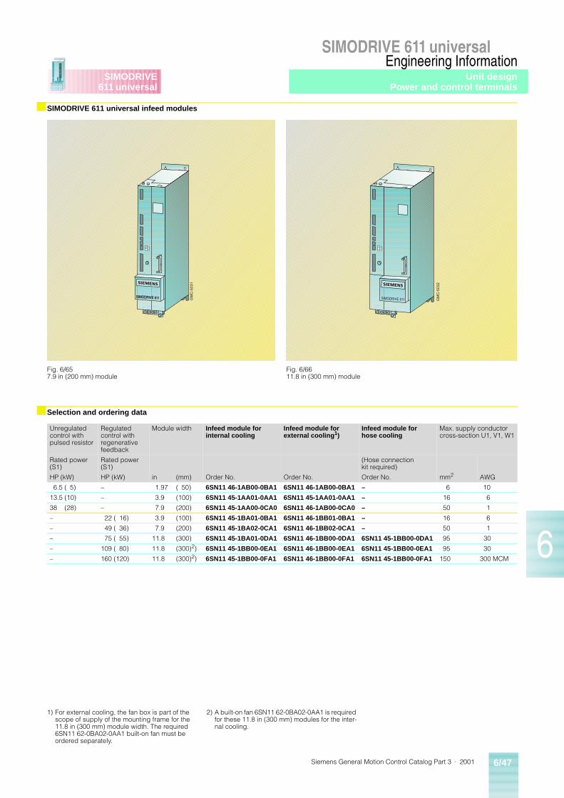
Siemens General Motion Control Catalog Part 3 · 2001 6/47
SIMODRIVE 611 universalEngineering Information
6
SIMODRIVE611 universal
■ SIMODRIVE 611 universal infeed modules
■ Selection and ordering data
GM
C-5
031
Fig. 6/657.9 in (200 mm) module
GM
C-5
032
Fig. 6/6611.8 in (300 mm) module
Unregulated control with pulsed resistor
Regulated control with regenerative feedback
Module width Infeed module for internal cooling
Infeed module for external cooling1)
Infeed module for hose cooling
Max. supply conductor cross-section U1, V1, W1
Rated power (S1)
Rated power (S1)
(Hose connection kit required)
HP (kW) HP (kW) in (mm) Order No. Order No. Order No. mm2 AWG
6.5 ( 5) – 1.97 ( 50) 6SN11 46-1AB00-0BA1 6SN11 46-1AB00-0BA1 – 6 10
13.5 (10) – 3.9 (100) 6SN11 45-1AA01-0AA1 6SN11 45-1AA01-0AA1 – 16 6
38 (28) – 7.9 (200) 6SN11 45-1AA00-0CA0 6SN11 46-1AB00-0CA0 – 50 1
– 22 ( 16) 3.9 (100) 6SN11 45-1BA01-0BA1 6SN11 46-1BB01-0BA1 – 16 6
– 49 ( 36) 7.9 (200) 6SN11 45-1BA02-0CA1 6SN11 46-1BB02-0CA1 – 50 1
– 75 ( 55) 11.8 (300) 6SN11 45-1BA01-0DA1 6SN11 46-1BB00-0DA1 6SN11 45-1BB00-0DA1 95 30
– 109 ( 80) 11.8 (300)2) 6SN11 45-1BB00-0EA1 6SN11 46-1BB00-0EA1 6SN11 45-1BB00-0EA1 95 30
– 160 (120) 11.8 (300)2) 6SN11 45-1BB00-0FA1 6SN11 46-1BB00-0FA1 6SN11 45-1BB00-0FA1 150 300 MCM
1) For external cooling, the fan box is part of the scope of supply of the mounting frame for the 11.8 in (300 mm) module width. The required 6SN11 62-0BA02-0AA1 built-on fan must be ordered separately.
2) A built-on fan 6SN11 62-0BA02-0AA1 is required for these 11.8 in (300 mm) modules for the inter-nal cooling.
Unit designPower and control terminals
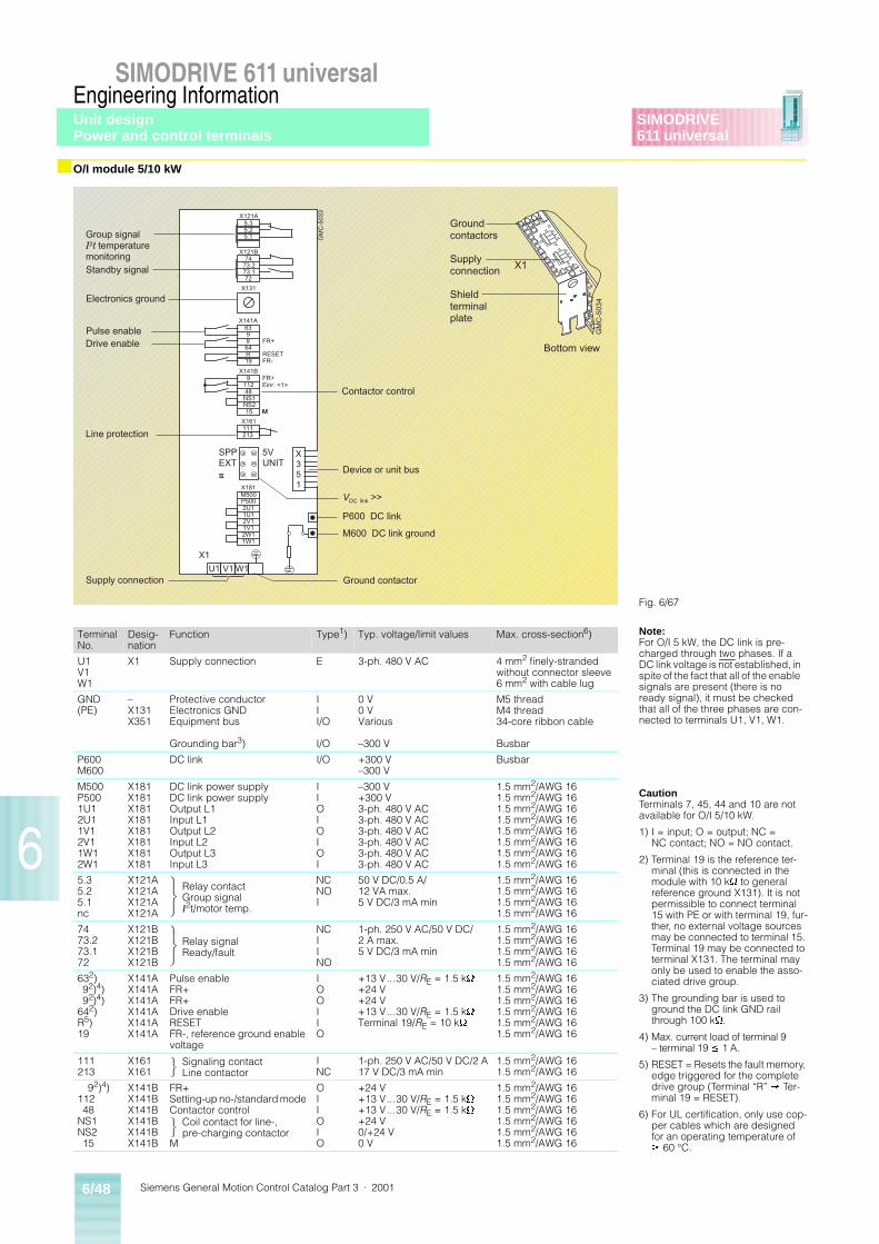
Siemens General Motion Control Catalog Part 3 · 20016/48
SIMODRIVE 611 universalEngineering Information
6
SIMODRIVE611 universal
■ O/I module 5/10 kW
5.35.2
74
73.172
73.2
63
964
19
9
R
9
48NS1
15
112
NS2
111213
M500
2U11U1
1V12W11W1
P500
2V1
X121B
X141A
X141B
X161
X181
FR+
RESETFR-
FR+Einr. <1>
5VUNIT
SPPEXT~~~
X351
W1V1U1
GM
C-5
033
X131
M
5.1
X121A
Standby signal
Group signalI2t temperaturemonitoring
Pulse enableDrive enable
Line protection
Device or unit bus
VDC link >>
P600 DC link
M600 DC link ground
Ground contactorSupply connection
Contactor control
M
Electronics ground
X1
X1
GM
C-5
034
Groundcontactors
Supplyconnection
Shieldterminalplate
Bottom view
Fig. 6/67
TerminalNo.
Desig-nation
Function Type1) Typ. voltage/limit values Max. cross-section6) Note:For O/I 5 kW, the DC link is pre-charged through two phases. If a DC link voltage is not established, in spite of the fact that all of the enable signals are present (there is no ready signal), it must be checked that all of the three phases are con-nected to terminals U1, V1, W1.
U1V1W1
X1 Supply connection E 3-ph. 480 V AC 4 mm2 finely-stranded without connector sleeve6 mm2 with cable lug
GND (PE)
–X131X351
Protective conductorElectronics GNDEquipment bus
Grounding bar3)
III/O
I/O
0 V0 VVarious
–300 V
M5 threadM4 thread34-core ribbon cable
Busbar
P600M600
DC link I/O +300 V–300 V
Busbar
M500P5001U12U11V12V11W12W1
X181X181X181X181X181X181X181X181
DC link power supplyDC link power supplyOutput L1Input L1Output L2Input L2Output L3Input L3
IIOIOIOI
–300 V+300 V3-ph. 480 V AC3-ph. 480 V AC3-ph. 480 V AC3-ph. 480 V AC3-ph. 480 V AC3-ph. 480 V AC
1.5 mm2/AWG 161.5 mm2/AWG 161.5 mm2/AWG 161.5 mm2/AWG 161.5 mm2/AWG 161.5 mm2/AWG 161.5 mm2/AWG 161.5 mm2/AWG 16
5.35.25.1nc
X121AX121AX121AX121A
NCNOI
50 V DC/0.5 A/12 VA max.5 V DC/3 mA min
1.5 mm2/AWG 161.5 mm2/AWG 161.5 mm2/AWG 161.5 mm2/AWG 16
7473.273.172
X121BX121BX121BX121B
NCIINO
1-ph. 250 V AC/50 V DC/2 A max. 5 V DC/3 mA min
1.5 mm2/AWG 161.5 mm2/AWG 161.5 mm2/AWG 161.5 mm2/AWG 16
632)92)4)92)4)
642)R5)19
X141AX141AX141AX141AX141AX141A
Pulse enableFR+FR+Drive enableRESETFR-, reference ground enable voltage
IOOIIO
+13 V...30 V/RE = 1.5 kW
+24 V+24 V+13 V...30 V/RE = 1.5 kW
Terminal 19/RE = 10 kW
1.5 mm2/AWG 161.5 mm2/AWG 161.5 mm2/AWG 161.5 mm2/AWG 161.5 mm2/AWG 161.5 mm2/AWG 16
111213
X161X161
INC
1-ph. 250 V AC/50 V DC/2 A17 V DC/3 mA min
1.5 mm2/AWG 161.5 mm2/AWG 16
92)4)11248
NS1NS215
X141BX141BX141BX141BX141BX141B
FR+Setting-up no-/standard mode Contactor control
M
OIIOIO
+24 V+13 V...30 V/RE = 1.5 kW
+13 V...30 V/RE = 1.5 kW
+24 V0/+24 V0 V
1.5 mm2/AWG 161.5 mm2/AWG 161.5 mm2/AWG 161.5 mm2/AWG 161.5 mm2/AWG 161.5 mm2/AWG 16
Relay contact Group signal I2t/motor temp.
Relay signalReady/fault
Signaling contactLine contactor
Coil contact for line-, pre-charging contactor
Unit designPower and control terminals
CautionTerminals 7, 45, 44 and 10 are not available for O/I 5/10 kW.
1) I = input; O = output; NC = NC contact; NO = NO contact.
2) Terminal 19 is the reference ter-minal (this is connected in the module with 10 kW to general reference ground X131). It is not permissible to connect terminal 15 with PE or with terminal 19, fur-ther, no external voltage sources may be connected to terminal 15. Terminal 19 may be connected to terminal X131. The terminal may only be used to enable the asso-ciated drive group.
3) The grounding bar is used to ground the DC link GND rail through 100 kW.
4) Max. current load of terminal 9 – terminal 19 £ 1 A.
5) RESET = Resets the fault memory, edge triggered for the complete drive group (Terminal “R” ® Ter-minal 19 = RESET).
6) For UL certification, only use cop-per cables which are designed for an operating temperature of ³ 60 °C.
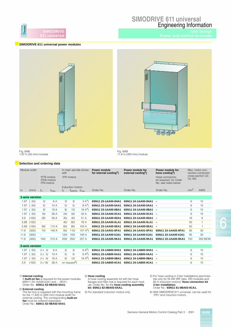
Siemens General Motion Control Catalog Part 3 · 2001 6/49
SIMODRIVE 611 universalEngineering Information
6
SIMODRIVE611 universal
■ SIMODRIVE 611 universal power modules
■ Selection and ordering data
GM
C-5
035
Fig. 6/681.97 in (50 mm) module
GM
C-5
036
U2 V2 W2
Fig. 6/6911.8 in (300 mm) module
Module width In main spindle drives with
Power modulefor internal cooling1)
Power module for external cooling2)
Power module for hose cooling3)
Max. motor con-nection conductor cross-section U2, V2, W2
1FT6 motors 1FK6 motors1FN motors
1PH motors Hose connection kit required, for Order No. see notes below
Induction motorsin (mm) In Imax. In Is640% Imax. Order No. Order No. Order No. mm2 AWG
1-axis version1.97 ( 50) 3/ 6 A 3/ 3/ 3 A4) 6SN11 23-1AA00-0HA1 6SN11 24-1AA00-0HA1 – 6 10
1.97 ( 50) 5/ 10 A 5/ 5/ 8 A4) 6SN11 23-1AA00-0AA1 6SN11 24-1AA00-0AA1 – 6 10
1.97 ( 50) 9/ 18 A 8/ 10/ 16 A4) 6SN11 23-1AA00-0BA1 6SN11 24-1AA00-0BA1 – 6 10
1.97 ( 50) 18/ 36 A 24/ 32/ 32 A 6SN11 23-1AA00-0CA1 6SN11 24-1AA00-0CA1 – 6 10
3.9 (100) 28/ 56 A 30/ 40/ 51 A 6SN11 23-1AA00-0DA1 6SN11 24-1AA00-0DA1 – 16 6
5.89 (150) – 45/ 60/ 76 A 6SN11 23-1AA00-0LA1 6SN11 24-1AA00-0LA1 – 50 1
5.89 (150) 56/ 112 A 60/ 80/ 102 A 6SN11 23-1AA00-0EA1 6SN11 24-1AA00-0EA1 – 50 1
11.8 (300) 70/ 140 A 85/ 110/ 127 A5) 6SN11 23-1AA01-0FA1 6SN11 24-1AA01-0FA1 6SN11 23-1AA02-0FA1 95 30
11.8 (300) – 120/ 150/ 193 A 6SN11 23-1AA00-0JA1 6SN11 24-1AA00-0JA1 6SN11 23-1AA00-0JA1 95 30
11.8 (300) 140/ 210 A 200/ 250/ 257 A 6SN11 23-1AA00-0KA1 6SN11 24-1AA00-0KA1 6SN11 23-1AA00-0KA1 150 300 MCM
2-axis version1.97 ( 50) 2 x 3/ 6 A 3/ 3/ 8 A6) 6SN11 23-1AB00-0HA1 6SN11 24-1AB00-0HA1 – 6 10
1.97 ( 50) 2 x 5/ 10 A 5/ 5/ 8 A6) 6SN11 23-1AB00-0AA1 6SN11 24-1AB00-0AA1 – 6 10
1.97 ( 50) 2 x 9/ 18 A 8/ 10/ 16 A6) 6SN11 23-1AB00-0BA1 6SN11 24-1AB00-0BA1 – 6 10
3.9 (100) 2 x 18/ 36 A on request6) 6SN11 23-1AB00-0CA1 6SN11 24-1AB00-0CA1 – 6 10
1) Internal coolingA built-on fan is required for the power modules 6SN11 23-1AA00-0JA1 and ...-0KA1; Order No.: 6SN11 62-0BA02-0AA1.
2) External coolingThe fan box is supplied with the mounting frame for the 11.820 in (300 mm) module width for external cooling. The corresponding built-on fan must be ordered separately: Order No.: 6SN11 62-0BA02-0AA1.
3) Hose coolingA hose cooling assembly kit with fan hose flanges and filter mat is required for each mod-ule. Order No. for the hose cooling assembly kit: 6SN11 62-0BA03-0AA1.
4) For standard induction motors only.
5) For hose cooling in 2-tier installations (permissi-ble only for 55 kW I/RF [aka. I/R] modules and 85 A induction motors): Hose connection kit 2-tier installation; Order No.: 6SN11 61-0BA03-0CA1.
6) With SIMODRIVE 611 universal, can be used for 1FE1 and induction motors.
Unit designPower and control terminals
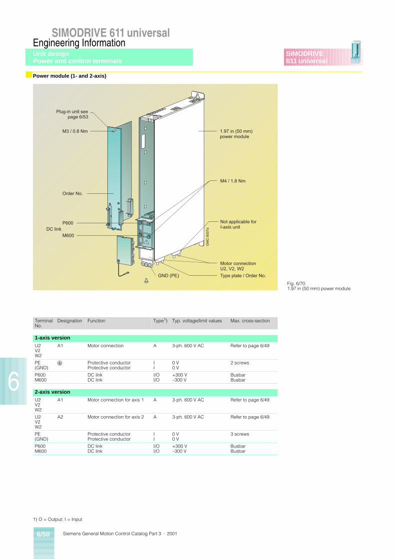
Siemens General Motion Control Catalog Part 3 · 20016/50
SIMODRIVE 611 universalEngineering Information
6
SIMODRIVE611 universal
■ Power module (1- and 2-axis)
GM
C-5
037a
Motor connectionU2, V2, W2
Plug-in unit see page 6/53
M3 / 0.8 Nm
Order No.
P600
M600DC link
1.97 in (50 mm)power module
M4 / 1.8 Nm
Not applicable forI-axis unit
Type plate / Order No.GND (PE)
Fig. 6/701.97 in (50 mm) power module
TerminalNo.
Designation Function Type1) Typ. voltage/limit values Max. cross-section
1-axis versionU2V2W2
A1 Motor connection A 3-ph. 600 V AC Refer to page 6/49
PE (GND)
U Protective conductorProtective conductor
II
0 V0 V
2 screws
P600M600
DC linkDC link
I/OI/O
+300 V–300 V
BusbarBusbar
2-axis versionU2V2W2
A1 Motor connection for axis 1 A 3-ph. 600 V AC Refer to page 6/49
U2V2W2
A2 Motor connection for axis 2 A 3-ph. 600 V AC Refer to page 6/49
PE (GND)
Protective conductorProtective conductor
II
0 V0 V
3 screws
P600M600
DC linkDC link
I/OI/O
+300 V–300 V
BusbarBusbar
1) O = Output; I = Input
Unit designPower and control terminals
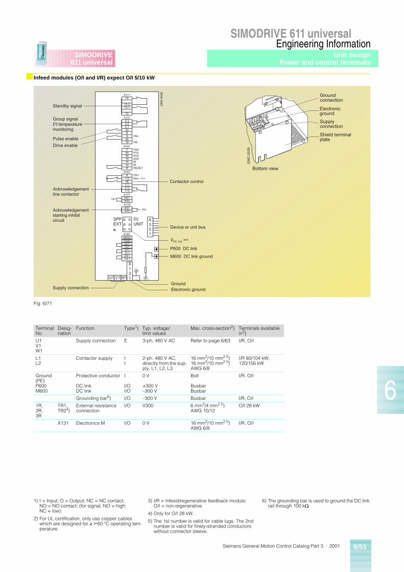
Siemens General Motion Control Catalog Part 3 · 2001 6/51
SIMODRIVE 611 universalEngineering Information
6
SIMODRIVE611 universal
■ Infeed modules (O/I and I/R) expect O/I 5/10 kW
74
73.273.1
72
5.3
5.163
96419
5.2
9
7
4410
15R
45
15
9
48111
113
112
213
NS1NS2
AS1AS2
M500
2U11U1
1V12W11W1
P500
2V1
X111
X121
X141
X161
X171
X172
X181
FR+
FR-
P24P15N15N24MMRESET
FR+Einr. <1>
<4>
<5>
5VUNIT
SPPEXT~~~
X131
X351
W1V1U1
GM
C-5
038
Standby signal
Group signalI2t temperaturemonitoring
Pulse enable
Drive enable
Acknowledgementline contactor
Acknowledgementstarting inhibitcircuit
Device or unit bus
VDC link >>
P600 DC link
M600 DC link ground
GroundElectronic groundSupply connection
Contactor control
GM
C-5
039
Groundconnection
Electronicground
Supplyconnection
Shield terminalplate
Bottom view
Fig. 6/71
TerminalNo.
Desig-nation
Function Type1) Typ. voltage/limit values
Max. cross-section2) Terminals available in3)
U1V1W1
Supply connection E 3-ph. 480 V AC Refer to page 6/63 I/R, O/I
L1L2
Contactor supply II
2-ph. 480 V AC, directly from the sup-ply, L1, L2, L3
16 mm2/10 mm2 5)16 mm2/10 mm2 5)AWG 6/8
I/R 80/104 kW, 120/156 kW
Ground (PE)P600M600
Protective conductor
DC linkDC link
I
I/OI/O
0 V
+300 V–300 V
Bolt
BusbarBusbar
I/R, O/I
Grounding bar6) I/O –300 V Busbar I/R, O/I
1R,2R,3R
TR1,TR24)
External resistance connection
I/O V300 6 mm2/4 mm2 5)AWG 10/12
O/I 28 kW
X131 Electronics M I/O 0 V 16 mm2/10 mm2 5)AWG 6/8
I/R, O/I
1) I = Input; O = Output; NC = NC contact; NO = NO contact; (for signal, NO = high; NC = low).
2) For UL certification, only use copper cables which are designed for a ³60 °C operating tem-perature.
3) I/R = Infeed/regenerative feedback module; O/I = non-regenerative.
4) Only for O/I 28 kW.
5) The 1st number is valid for cable lugs. The 2nd number is valid for finely-stranded conductors without connector sleeve.
6) The grounding bar is used to ground the DC link rail through 100 kW.
Unit designPower and control terminals
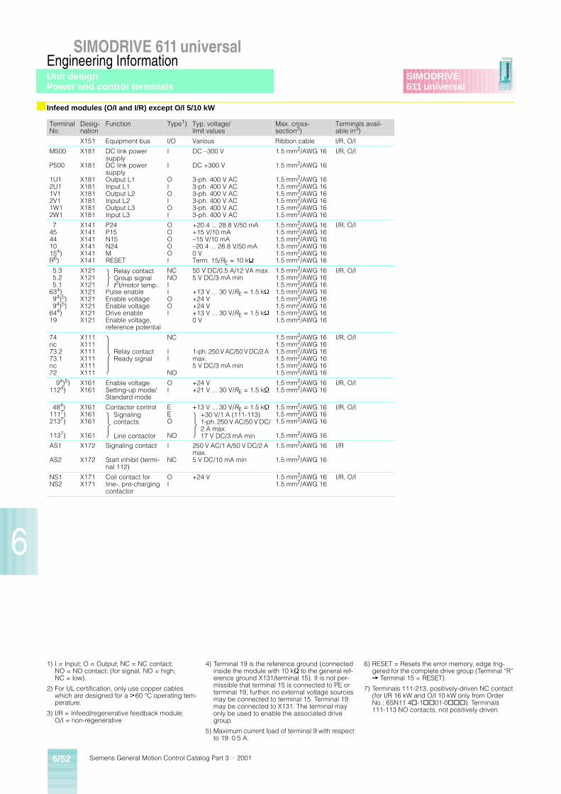
Siemens General Motion Control Catalog Part 3 · 20016/52
SIMODRIVE 611 universalEngineering Information
6
SIMODRIVE611 universal
■ Infeed modules (O/I and I/R) except O/I 5/10 kW
TerminalNo.
Desig-nation
Function Type1) Typ. voltage/limit values
Max. cross-section2)
Terminals avail-able in3)
X151 Equipment bus I/O Various Ribbon cable I/R, O/I
M500
P500
1U12U11V12V11W12W1
X181
X181
X181X181X181X181X181X181
DC link power supplyDC link power supplyOutput L1Input L1Output L2Input L2Output L3Input L3
I
I
OIOIOI
DC –300 V
DC +300 V
3-ph. 400 V AC3-ph. 400 V AC3-ph. 400 V AC3-ph. 400 V AC3-ph. 400 V AC3-ph. 400 V AC
1.5 mm2/AWG 16
1.5 mm2/AWG 16
1.5 mm2/AWG 161.5 mm2/AWG 161.5 mm2/AWG 161.5 mm2/AWG 161.5 mm2/AWG 161.5 mm2/AWG 16
I/R, O/I
7454410154)R6)
X141X141X141X141X141X141
P24P15N15N24MRESET
OOOOOI
+20.4 ... 28.8 V/50 mA+15 V/10 mA–15 V/10 mA–20.4 ... 28.8 V/50 mA0 VTerm. 15/RE = 10 kW
1.5 mm2/AWG 161.5 mm2/AWG 161.5 mm2/AWG 161.5 mm2/AWG 161.5 mm2/AWG 161.5 mm2/AWG 16
I/R, O/I
5.35.25.1
634)94)5)94)5)
644)19
X121X121X121X121X121X121X121X121
Pulse enableEnable voltageEnable voltageDrive enableEnable voltage, reference potential
NCNOIIOOI
50 V DC/0.5 A/12 VA max.5 V DC/3 mA min
+13 V ... 30 V/RE = 1.5 kW
+24 V+24 V+13 V ... 30 V/RE = 1.5 kW
0 V
1.5 mm2/AWG 161.5 mm2/AWG 161.5 mm2/AWG 161.5 mm2/AWG 161.5 mm2/AWG 161.5 mm2/AWG 161.5 mm2/AWG 161.5 mm2/AWG 16
I/R, O/I
74nc73.273.1nc72
X111X111X111X111X111X111
NC
II
NO
1-ph. 250 V AC/50 V DC/2 A max. 5 V DC/3 mA min
1.5 mm2/AWG 161.5 mm2/AWG 161.5 mm2/AWG 161.5 mm2/AWG 161.5 mm2/AWG 161.5 mm2/AWG 16
I/R, O/I
94)5)1124)
X161X161
Enable voltageSetting-up mode/Standard mode
OI
+24 V+21 V ... 30 V/RE = 1.5 kW
1.5 mm2/AWG 161.5 mm2/AWG 16
I/R, O/I
484)1117)2137)
1137)
X161X161X161
X161
Contactor control EEÖ
NO
+13 V ... 30 V/RE = 1.5 kW 1.5 mm2/AWG 161.5 mm2/AWG 161.5 mm2/AWG 16
1.5 mm2/AWG 16
I/R, O/I
AS1
AS2
X172
X172
Signaling contact
Start inhibit (termi-nal 112)
I
NC
250 V AC/1 A/50 V DC/2 A max.5 V DC/10 mA min
1.5 mm2/AWG 16
1.5 mm2/AWG 16
I/R
NS1NS2
X171X171
Coil contact for line-, pre-charging contactor
OI
+24 V 1.5 mm2/AWG 161.5 mm2/AWG 16
I/R, O/I
Relay contact Group signalI2t/motor temp.
Relay contactReady signal
Signaling contacts
Line contactor
+30 V/1 A (111-113)1-ph. 250 V AC/50 V DC/2 A max.17 V DC/3 mA min
1) I = Input; O = Output; NC = NC contact; NO = NO contact; (for signal, NO = high; NC = low).
2) For UL certification, only use copper cables which are designed for a ³60 °C operating tem-perature.
3) I/R = Infeed/regenerative feedback module;O/I = non-regenerative
4) Terminal 19 is the reference ground (connected inside the module with 10 kW to the general ref-erence ground X131/terminal 15). It is not per-missible that terminal 15 is connected to PE or terminal 19, further, no external voltage sources may be connected to terminal 15. Terminal 19 may be connected to X131. The terminal may only be used to enable the associated drive group.
5) Maximum current load of terminal 9 with respect to 19: 0.5 A.
6) RESET = Resets the error memory, edge trig-gered for the complete drive group (Terminal “R” ® Terminal 15 = RESET).
7) Terminals 111-213, positively-driven NC contact (for I/R 16 kW and O/I 10 kW only from Order No.: 6SN11 4@-1@@01-0@@@). Terminals 111-113 NO contacts, not positively driven.
Unit designPower and control terminals
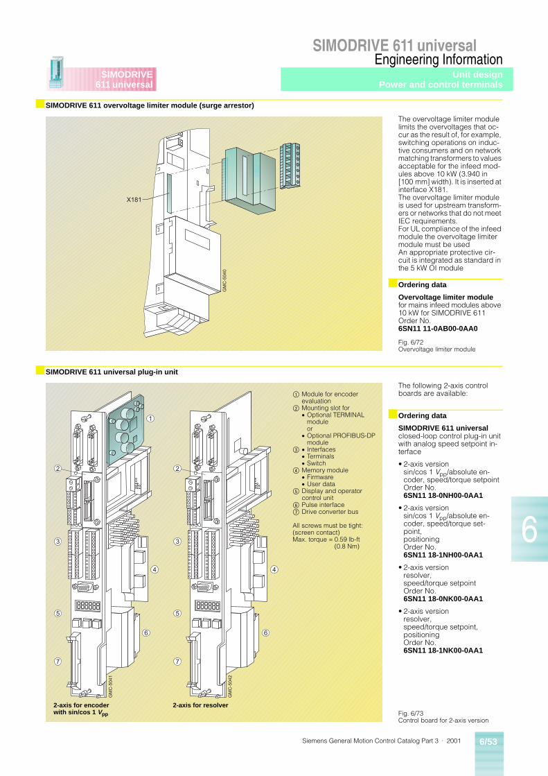
Siemens General Motion Control Catalog Part 3 · 2001 6/53
SIMODRIVE 611 universalEngineering Information
6
SIMODRIVE611 universal
■ SIMODRIVE 611 overvoltage limiter module (surge arrestor)
The overvoltage limiter module limits the overvoltages that oc-cur as the result of, for example, switching operations on induc-tive consumers and on network matching transformers to values acceptable for the infeed mod-ules above 10 kW (3.940 in [100 mm] width). It is inserted at interface X181.The overvoltage limiter module is used for upstream transform-ers or networks that do not meet IEC requirements.For UL compliance of the infeed module the overvoltage limiter module must be usedAn appropriate protective cir-cuit is integrated as standard in the 5 kW OI module
■ Ordering data
Overvoltage limiter modulefor mains infeed modules above 10 kW for SIMODRIVE 611Order No. 6SN11 11-0AB00-0AA0
■ SIMODRIVE 611 universal plug-in unit
The following 2-axis control boards are available:
■ Ordering data
SIMODRIVE 611 universalclosed-loop control plug-in unit with analog speed setpoint in-terface
• 2-axis versionsin/cos 1 Vpp/absolute en-coder, speed/torque setpointOrder No. 6SN11 18-0NH00-0AA1
• 2-axis versionsin/cos 1 Vpp/absolute en-coder, speed/torque set-point,positioningOrder No. 6SN11 18-1NH00-0AA1
• 2-axis versionresolver,speed/torque setpointOrder No. 6SN11 18-0NK00-0AA1
• 2-axis versionresolver,speed/torque setpoint,positioningOrder No. 6SN11 18-1NK00-0AA1
GM
C-5
040
X181
Fig. 6/72Overvoltage limiter module
1
2
3
5
7
6
4
GM
C-5
041
2
3
5
7
6
4
GM
C-5
042
$ Module for encoder evaluation
% Mounting slot for� Optional TERMINAL
moduleor
� Optional PROFIBUS-DP module
& � Interfaces� Terminals� Switch
( Memory module� Firmware� User data
) Display and operator control unit
* Pulse interface+ Drive converter bus
All screws must be tight:(screen contact)Max. torque = 0.59 lb-ft
(0.8 Nm)
2-axis for encoder with sin/cos 1 Vpp
2-axis for resolverFig. 6/73Control board for 2-axis version
Unit designPower and control terminals
Siemens General Motion Control Catalog Part 3 · 20016/54
SIMODRIVE 611 universalEngineering Information
6
SIMODRIVE611 universal
■ SIMODRIVE 611 universal plug-in unit
The following 1-axis control board is available:
■ Ordering data
SIMODRIVE 611 universalclosed-loop control plug-in unit with analog speed setpoint in-terface
• 1-axis versionresolver,speed/torque setpointOrder No. 6SN11 18-0NJ00-0AA1
• 1-axis versionresolver,speed/torque setpoint,positioningOrder No. 6SN11 18-1NJ00-0AA1
2
3
5
7
6
4
GM
C-5
043
� These interfaces have no function for the 1-axis version
% Mounting slot for� Optional TERMINAL module
or� Optional PROFIBUS-DP module
& � Interfaces� Terminals� Switch
( Memory module� Firmware� User data
) Display and operator control unit* Pulse interface+ Drive converter bus
All screws must be tight:(screen contact)Max. torque = 0.59 lb-ft (0.8 Nm)
Fig. 6/74Control board for 1-axis version
Unit designPower and control terminals
Siemens General Motion Control Catalog Part 3 · 2001 6/55
SIMODRIVE 611 universalEngineering Information
6
SIMODRIVE611 universal
■ SIMODRIVE 611 universal plug-in unit
Using the start inhibit
The “start inhibit” function is provided in the SIMODRIVE 611 drive modules.
The start inhibit function pre-vents a synchronous – or induc-tion motor drive unexpectedly starting from standstill. This cir-cuit macro can be used in the “safe standstill” machine func-tion. The external machine con-trol must have initiated and guaranteed that the machine has come to a complete stand-still beforehand. The power feed from the converter to the motor is interrupted with the start in-hibit (motor rotation). This is based on the Draft IEC 204 No. 44/184/CDV from 15.06.95.
The remaining risk, is in this case, if two errors/faults occur simultaneously in the power section; the motor rotates (jolts) through a small angle (1 FT motors: 4 pole 90°, 6 pole 60°, 8 pole 45°, induction motors: in the vicinity of the remanence, max. 1 slot pitch, which approx-imately corresponds to 5° 15°.
The start inhibit function, when correctly used, must be looped-in in the line contactor circuit or emergency off circuit with the positively-driven signaling con-tact AS1/AS2. The associated drive must be electrically isolat-ed from the supply if the start inhibit relay function is not plau-sible, referred to the machine operating mode; e.g. via the line contactor in the infeed mod-ule. The start inhibit and the associated operating mode may only be used again after the fault has been removed.
Board-specific terminals and interfaces
The board-specific terminals and interfaces are available for drive A and B.
■ Start inhibit in the drive modules (SAFE OFF)
75A
M
GM
C-5
044a
Button forPOWER ON�RESET
Signaling terminalsAS1AS2 FAULT
LED redX421
Terminals for supplyand pulse enable
X431
P24M24966319
Analog outputs
X441(reference)
X34
M DAU1 DAU2
Terminals, drive A56.A14.A24.A20.A65.A9I0.AI1.AI2.AI3.A
A+.AA�.AB+.AB�.AR+.AR�.AO0.AO1.AO2.AO3.A
X451
X461
EquipmentbusX351
Terminals, drive B56.B14.B24.B20.B65.B9I0.BI1.BI2.BI3.B
A+.BA�.BB+.BB�.BR+.BR�.BO0.BO1.BO2.BO3.B
X452
X462
Motor encoder, drive BMotor encoder, drive AX411 X412
Mounting slot for 1)
Optional TERMINAL moduleX422 (inputs)X432 (outputs)orOptional PROFIBUS-DPX423 (interface)
Switch S1
Serial interface(RS232/RS485)X471
Displayandoperator control unit
75.A16.A75.B16.B15
-X41
1R
-X41
2
-X42
1-X
431
F-X
441
S1
-X471
P+ �
-X35
1
Fig. 6/75Plug-in unit
ImportantThe functions “safety stop” and “setting-up operation” are not safety functions in the sense of the Machinery Direc-tive 89/392/EEC. They only support the measures which have to be untertaken by the user himself.
Electrical isolation is not pro-vided by the start inhibit func-tion, and it does not provide protection against “electric shock”.
The complete machine must always be electrically isolated from the line supply through the main switch if any work is to be carried-out on the machine or system, e.g. maintenance service or cleaning work (EN 60 204/5.3).
TerminalNo.
Designation Function Type2) Technical data
Signaling terminal, start inhibit (X421)AS1 X421 Signaling contact
Start inhibitNC Connector type:
Max. conductor cross-section:
Contact:
Contact load:
2-pin connector strip
2.5 mm2/AWG 14
Floating NC contact
at 250 VAC max. 1 Aat 30 VDC max. 2 A
AS2 X421 Checkback signalfrom terminal 663
NC
Relay, safestart inhibit
AS1
AS2
T.663
Pulses not enabled (T.663)The gating pulses of the powertransistors are inhibited.
GM
C-5
045
Relay, safestart inhibit
AS1
AS2
T.663
Pulses enabled (T.663)The gating pulses of the powertransistors are enabled.
GM
C-5
046
1) Dummy cover removed, no option module inserted.
2) NC contact.
Unit designPower and control terminals
Siemens General Motion Control Catalog Part 3 · 20016/56
SIMODRIVE 611 universalEngineering Information
6
SIMODRIVE611 universal
■ SIMODRIVE 611 universal plug-in unit ■ Start inhibit in the drive modules (SAFE OFF)(continued)Terminal
No.Designation Function Type1) Technical data
Terminals for supply and pulse enable (X431)X431 Connector type:
Max. conductor cross-section:
5-pin connector
1.5 mm2/AWG 16
P24 X431.1 External power supply for digital outputs (+24 V)
V Voltage tolerance(including ripple): 10 V to 30 V
M24 X431.2 Reference for the external supply
V
The external supply is required for the following digital outputs:• 8 outputs for drive-specific terminals (X461, O0.A – O3.A/X462, O0.B – O3.B)• 8 outputs of the optional TERMINAL module (X432, O4 – O11)
When dimensioning the external power supply, the total current of all of the digital outputs must be taken into account.
Maximum total current:• for the control board (all 8 outputs):• for the optional TERMINAL module (all 8 outputs):
A2.4480 mA
Example:
Board/module Outputs Dimensioning the external supplyControl boardControl board + optional TERMINAL module
88 + 8
max. 1.5 Amax. (1.5 A + 280 mA)
® 24 V/1.5 A® 24 V/1.8 A
9 X431.3 Enable voltage(+24 V)
V Reference:
Max. current (for the complete group):
T. 19
500 mA
Note:The enable voltage (terminal 9) can be used to pro-vide the enable signals (e.g. pulse enable) as 24 V auxiliary voltage.
663 X431.4 Pulse enable(+24 V)
I Voltage tolerance(including ripple):
Current drain, typical:
21 V to 30 V
25 mA at 24 V
Note:The pulse enable acts simultaneously on drive A and drive B. When the pulse enable is withdrawn, the drives “coast down” unbraked.
19 X431.5 Reference(Reference for all digital inputs)
V Note:If the enable signals are to be controlled from an ex-ternal voltage and not from terminal 9, then the refer-ence potential (ground) of the external source must be connected to this terminal.
Serial interface (X471)– X471 Serial interface for
“SimoCom U”IO Connector type: 9-pin D-sub socket connector
Note:• Online operation via the serial RS232/RS485 inter-
face
Equipment bus (X351)– X351 Drive converter bus IO Ribbon cable:
Voltages:
Signals:
34-pin
various
various
Test sockets (X34)DAU1 X34 Test socket 12) MA Test socket:
Resolution:
Voltage range:
Maximum current:
Æ 2 mm
8 bit
0 V to 5 V
3 mA
DAU2 X34 Test socket 22) MA
M X34 Reference MA
As a result of a hazard analy-sis/risk analysis which must be executed according to the Machinery Directive 89/392/EEC and EN 292; pr EN 954; and pr EN 1050, the machine manufacturer must configure the safety circuit for the com-plete machine taking into account all of the integrated components for his machine types and version of them. This also includes the electric drives.
1) I = Input; V = Supply; IO = Input/output; MA = Analog measuring signal.
2) Can be freely parameterized.
Unit designPower and control terminals
Siemens General Motion Control Catalog Part 3 · 2001 6/57
SIMODRIVE 611 universalEngineering Information
6
SIMODRIVE611 universal
■ SIMODRIVE 611 universal plug-in unit
Drive-specific terminals
The drive-specific terminals are available for both drive A and drive B.
■ Pin assignment of the interface
Assignment of X411/X412 for encoders with sin/cos 1 Vpp
Connector type: 25-pin D-Sub, plug connector
Assignment of X411/X412 for resolvers
Connector type: 25-pin D-Sub, plug connector
Terminals Function Type1) Technical data
Drive A Drive B
No.Desig-nation No.
Desig-nation
Encoder connection (X411, X412)– X411 – – Motor encoder
connection, drive AI Literature:
SIMODRIVE 611, Planning Guide, Section “Indirect and direct position sensing”
Encoder limiting frequencies:• Encoder with sin/cos 1 Vpp: 350 kHz• Resolver 375 Hz
– – – X412 Motor encoder connection, drive B
I
Pin Signal name Pin Signal name
1 P_Encoder 14 5 V sense
2 M_Encoder 15 EnDat_DAT
3 A 16 0 V sense
4 *A 17 R
5 Inner screen 18 *R
6 B 19 C
7 *B 20 *C
8 Inner screen 21 D
9 Reserved 22 *D
10 EnDat_CLK 23 *EnDat_DAT
11 Reserved 24 Inner screen
12 *EnDat_CLK 25 –Temp
13 +Temp – –
Cable Order No.
Incremental motor encoder 6FX@ 002-2CA31-1@@0
Absolute motor encoder (EnDat) 6FX@ 002-2EQ10-1@@0
Pin Signal name Pin Signal name
1 Reserved 14 Reserved
2 M_Encoder 15 Reserved
3 SIN_PLUS 16 Reserved
4 SIN_MINUS 17 Reserved
5 Inner screen 18 Reserved
6 COS_PLUS 19 Reserved
7 COS_MINUS 20 Reserved
8 Inner screen 21 Reserved
9 Excitation_Pos 22 Reserved
10 Reserved 23 Reserved
11 Excitation_Neg 24 Inner screen
12 Reserved 25 Temp–
13 Temp+ – –
Cable Order No.
Resolver in the motor 6FX@ 002-2CF02-1@@0
1) I = Input.
Unit designPower and control terminals
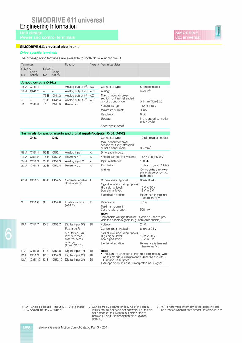
Siemens General Motion Control Catalog Part 3 · 20016/58
SIMODRIVE 611 universalEngineering Information
6
SIMODRIVE611 universal
■ SIMODRIVE 611 universal plug-in unit
Drive-specific terminals
The drive-specific terminals are available for both drive A and drive B.
Terminals Function Type1) Technical data
Drive A Drive B
No.Desig-nation No.
Desig-nation
Analog outputs (X441)75.A X441.1 – – Analog output 12) AO Connector type:
Wiring:
Max. conductor cross-section for finely-stranded or solid conductors:
Voltage range:
Maximum current:
Resolution:
Update:
Short-circuit proof
5-pin connector
refer to3)
0.5 mm2/AWG 20
–10 to +10 V
3 mA
8 bit
in the speed controller clock cycle
16.A X441.2 – – Analog output 22) AO
– – 75.B X441.3 Analog output 12) AO
– – 16.B X441.4 Analog output 22) AO
15 X441.5 15 X441.5 Reference –
Terminals for analog inputs and digital inputs/outputs (X451, X452)X451 X452 Connector type:
Max. conductor cross-section for finely-stranded or solid conductors:
10-pin plug connector
0.5 mm2
56.A X451.1 56.B X452.1 Analog input 1 AI Differential inputs
Voltage range (limit values):
Input resistance:
Resolution:
Wiring:
–12.5 V to +12.5 V
100 kW
14 bits (sign + 13 bits)
Connect the cable with the braided screen at both ends
14.A X451.2 14.B X452.2 Reference 1 AI
24.A X451.3 24.B X452.3 Analog input 2 AI
20.A X451.4 20.B X452.4 Reference 2 AI
65.A X451.5 65.B X452.5 Controller enable drive-specific
I Current drain, typical:
Signal level (including ripple)High signal level:Low signal level:
Electrical isolation:
6 mA at 24 V
15 V to 30 V–3 V to 5 V
Reference is terminal 19/terminal M24
9 X451.6 9 X452.6 Enable voltage (+24 V)
V Reference:
Maximum current (for the total group):
T. 19
500 mA
Note:The enable voltage (terminal 9) can be used to pro-vide the enable signals (e.g. controller enable).
I0.A X451.7 I0.B X452.7 Digital input 02)
Fast input3)
e.g. for equiva-lent zero mark, external block change (from SW 3.1)
DI Voltage:
Current drain, typical:
Signal level (including ripple)High signal level:Low signal level:
Electrical isolation:
24 V
6 mA at 24 V
15 V to 30 V–3 V to 5 V
Reference is terminal 19/terminal M24
I1.A X451.8 I1.B X452.8 Digital input 12) DI Note:• The parameterization of the input terminals as well
as the standard assignment is described in 611 u Function Description
• An open-circuit input is interpreted as 0 signal
I2.A X451.9 I2.B X452.9 Digital input 22) DI
I3.A X451.10 I3.B X452.10 Digital input 32) DI
1) AO = Analog output; I = Input; DI = Digital input; AI = Analog input; V = Supply.
2) Can be freely parameterized. All of the digital inputs are de-bounced per software. For the sig-nal detection, this results in a delay time of between 1 and 2 interpolation clock cycles (P1010).
3) I0.x is hardwired internally to the position sens-ing function where it acts almost instantaneously.
Unit designPower and control terminals
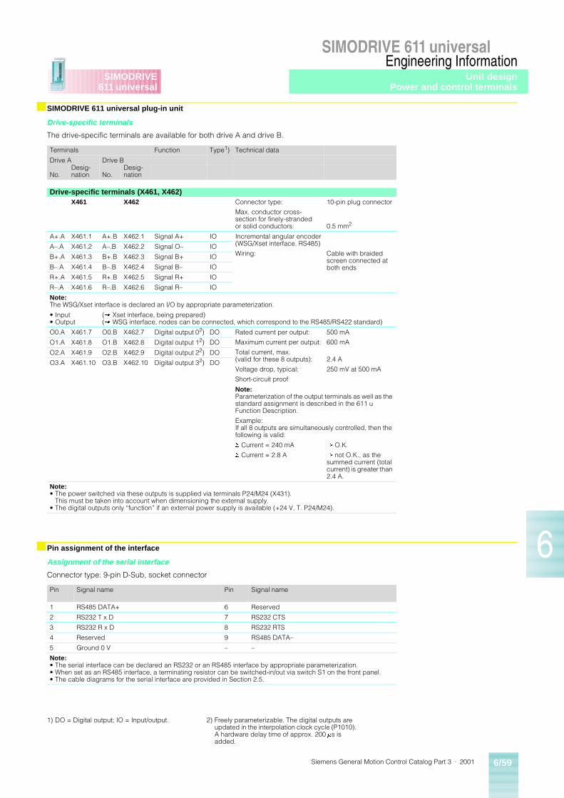
Siemens General Motion Control Catalog Part 3 · 2001 6/59
SIMODRIVE 611 universalEngineering Information
6
SIMODRIVE611 universal
■ SIMODRIVE 611 universal plug-in unit
Drive-specific terminals
The drive-specific terminals are available for both drive A and drive B.
■ Pin assignment of the interface
Assignment of the serial interface
Connector type: 9-pin D-Sub, socket connector
Terminals Function Type1) Technical data
Drive A Drive B
No.Desig-nation No.
Desig-nation
Drive-specific terminals (X461, X462)X461 X462 Connector type:
Max. conductor cross-section for finely-stranded or solid conductors:
10-pin plug connector
0.5 mm2
A+.A X461.1 A+.B X462.1 Signal A+ IO Incremental angular encoder(WSG/Xset interface, RS485)
Wiring: Cable with braided screen connected at both ends
A–.A X461.2 A–.B X462.2 Signal O– IO
B+.A X461.3 B+.B X462.3 Signal B+ IO
B–.A X461.4 B–.B X462.4 Signal B– IO
R+.A X461.5 R+.B X462.5 Signal R+ IO
R–.A X461.6 R–.B X462.6 Signal R– IO
Note:The WSG/Xset interface is declared an I/O by appropriate parameterization.
• Input• Output
(® Xset interface, being prepared)(® WSG interface, nodes can be connected, which correspond to the RS485/RS422 standard)
O0.A X461.7 O0.B X462.7 Digital output 02) DO Rated current per output:
Maximum current per output:
Total current, max.(valid for these 8 outputs):
Voltage drop, typical:
Short-circuit proof
500 mA
600 mA
2.4 A
250 mV at 500 mA
O1.A X461.8 O1.B X462.8 Digital output 12) DO
O2.A X461.9 O2.B X462.9 Digital output 22) DO
O3.A X461.10 O3.B X462.10 Digital output 32) DO
Note:Parameterization of the output terminals as well as the standard assignment is described in the 611 u Function Description.
Example:If all 8 outputs are simultaneously controlled, then the following is valid:
S Current = 240 mA
S Current = 2.8 A
® O.K.
® not O.K., as the summed current (total current) is greater than 2.4 A.
Note:• The power switched via these outputs is supplied via terminals P24/M24 (X431).
This must be taken into account when dimensioning the external supply.• The digital outputs only “function” if an external power supply is available (+24 V, T. P24/M24).
Pin Signal name Pin Signal name
1 RS485 DATA+ 6 Reserved
2 RS232 T x D 7 RS232 CTS
3 RS232 R x D 8 RS232 RTS
4 Reserved 9 RS485 DATA–
5 Ground 0 V – –
Note:• The serial interface can be declared an RS232 or an RS485 interface by appropriate parameterization.• When set as an RS485 interface, a terminating resistor can be switched-in/out via switch S1 on the front panel.• The cable diagrams for the serial interface are provided in Section 2.5.
1) DO = Digital output; IO = Input/output. 2) Freely parameterizable. The digital outputs are updated in the interpolation clock cycle (P1010). A hardware delay time of approx. 200 ms is added.
Unit designPower and control terminals
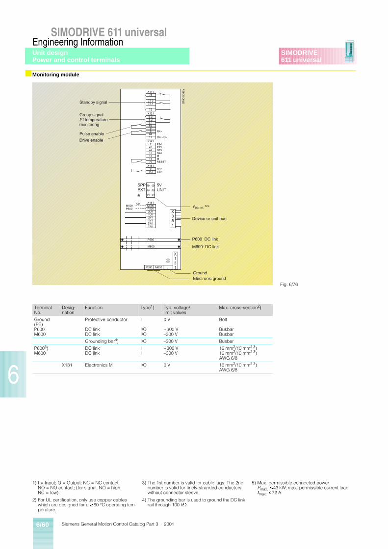
Siemens General Motion Control Catalog Part 3 · 20016/60
SIMODRIVE 611 universalEngineering Information
6
SIMODRIVE611 universal
■ Monitoring module
74
73.273.1
72
5.3
5.163
96419
5.2
9
7
4410
15R
45
15
9112
M500
2U11U1
1V12W11W1
P500
2V1
X111
X121
X141
X161
X181
FR+
FR- <6>
P24P15N15N24MMRESET
FR+Einr.
5VUNIT
SPPEXT~~~
X131
X351
GM
C-5
047a
M600P600
<3>
P600
M600
M600P600
Standby signal
Group signalI2t temperaturemonitoring
Pulse enable
Drive enable
Device-or unit bus
VDC link >>
P600 DC link
M600 DC link
GroundElectronic ground
Fig. 6/76
TerminalNo.
Desig-nation
Function Type1) Typ. voltage/limit values
Max. cross-section2)
Ground (PE)P600M600
Protective conductor
DC linkDC link
I
I/OI/O
0 V
+300 V–300 V
Bolt
BusbarBusbar
Grounding bar4) I/O –300 V Busbar
P6005)M600
DC linkDC link
II
+300 V–300 V
16 mm2/10 mm2 3)16 mm2/10 mm2 3)AWG 6/8
X131 Electronics M I/O 0 V 16 mm2/10 mm2 3)AWG 6/8
1) I = Input; O = Output; NC = NC contact; NO = NO contact; (for signal, NO = high; NC = low).
2) For UL certification, only use copper cables which are designed for a ³60 °C operating tem-perature.
3) The 1st number is valid for cable lugs. The 2nd number is valid for finely-stranded conductors without connector sleeve.
4) The grounding bar is used to ground the DC link rail through 100 kW.
5) Max. permissible connected power Pmax. £43 kW, max. permissible current load Imax. £72 A.
Unit designPower and control terminals
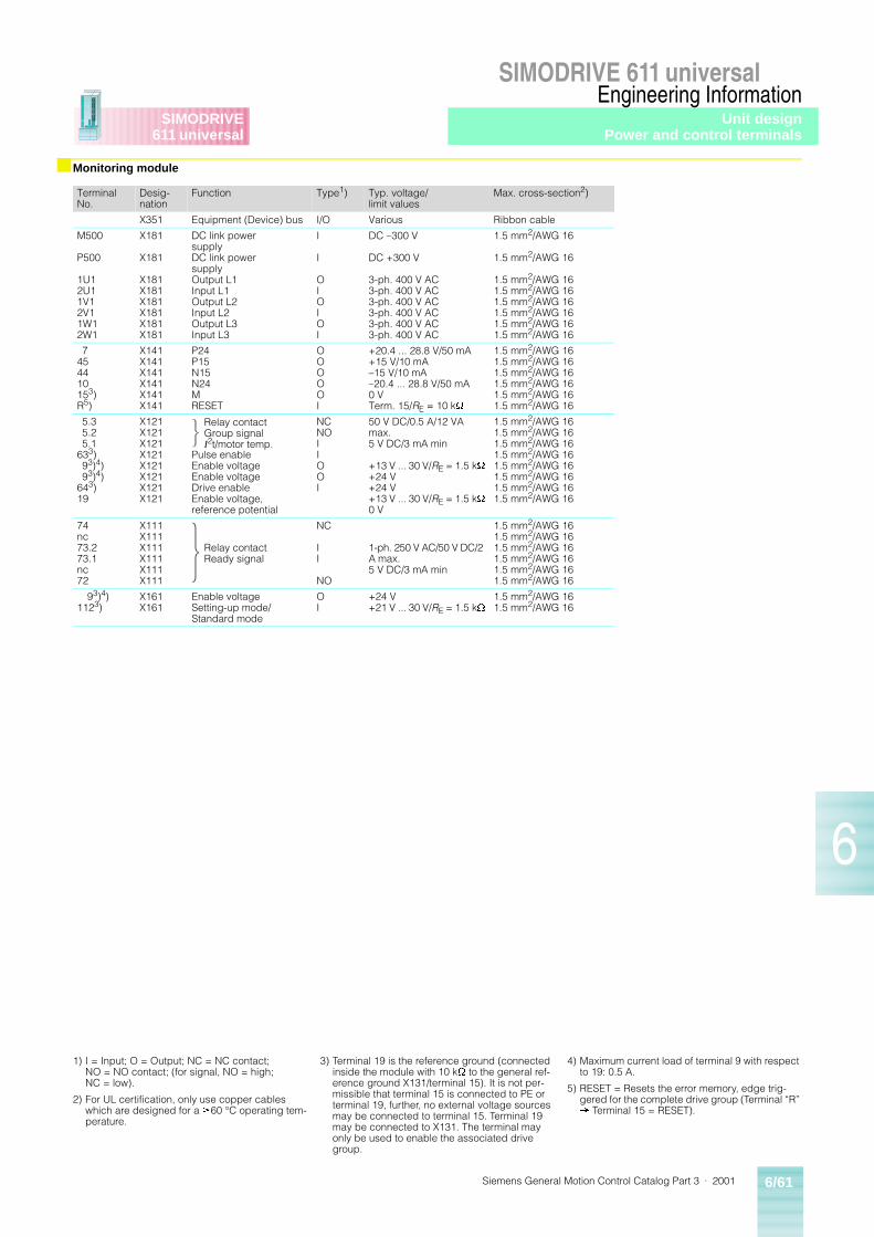
Siemens General Motion Control Catalog Part 3 · 2001 6/61
SIMODRIVE 611 universalEngineering Information
6
SIMODRIVE611 universal
■ Monitoring module
TerminalNo.
Desig-nation
Function Type1) Typ. voltage/limit values
Max. cross-section2)
X351 Equipment (Device) bus I/O Various Ribbon cable
M500
P500
1U12U11V12V11W12W1
X181
X181
X181X181X181X181X181X181
DC link power supplyDC link power supplyOutput L1Input L1Output L2Input L2Output L3Input L3
I
I
OIOIOI
DC –300 V
DC +300 V
3-ph. 400 V AC3-ph. 400 V AC3-ph. 400 V AC3-ph. 400 V AC3-ph. 400 V AC3-ph. 400 V AC
1.5 mm2/AWG 16
1.5 mm2/AWG 16
1.5 mm2/AWG 161.5 mm2/AWG 161.5 mm2/AWG 161.5 mm2/AWG 161.5 mm2/AWG 161.5 mm2/AWG 16
7454410153)R5)
X141X141X141X141X141X141
P24P15N15N24MRESET
OOOOOI
+20.4 ... 28.8 V/50 mA+15 V/10 mA–15 V/10 mA–20.4 ... 28.8 V/50 mA0 VTerm. 15/RE = 10 kW
1.5 mm2/AWG 161.5 mm2/AWG 161.5 mm2/AWG 161.5 mm2/AWG 161.5 mm2/AWG 161.5 mm2/AWG 16
5.35.25.1
633)93)4)93)4)
643)19
X121X121X121X121X121X121X121X121
Pulse enableEnable voltageEnable voltageDrive enableEnable voltage, reference potential
NCNOIIOOI
50 V DC/0.5 A/12 VA max.5 V DC/3 mA min
+13 V ... 30 V/RE = 1.5 kW
+24 V+24 V+13 V ... 30 V/RE = 1.5 kW
0 V
1.5 mm2/AWG 161.5 mm2/AWG 161.5 mm2/AWG 161.5 mm2/AWG 161.5 mm2/AWG 161.5 mm2/AWG 161.5 mm2/AWG 161.5 mm2/AWG 16
74nc73.273.1nc72
X111X111X111X111X111X111
NC
II
NO
1-ph. 250 V AC/50 V DC/2 A max. 5 V DC/3 mA min
1.5 mm2/AWG 161.5 mm2/AWG 161.5 mm2/AWG 161.5 mm2/AWG 161.5 mm2/AWG 161.5 mm2/AWG 16
93)4)1123)
X161X161
Enable voltageSetting-up mode/Standard mode
OI
+24 V+21 V ... 30 V/RE = 1.5 kW
1.5 mm2/AWG 161.5 mm2/AWG 16
Relay contact Group signalI2t/motor temp.
Relay contactReady signal
1) I = Input; O = Output; NC = NC contact; NO = NO contact; (for signal, NO = high; NC = low).
2) For UL certification, only use copper cables which are designed for a ³60 °C operating tem-perature.
3) Terminal 19 is the reference ground (connected inside the module with 10 kW to the general ref-erence ground X131/terminal 15). It is not per-missible that terminal 15 is connected to PE or terminal 19, further, no external voltage sources may be connected to terminal 15. Terminal 19 may be connected to X131. The terminal may only be used to enable the associated drive group.
4) Maximum current load of terminal 9 with respect to 19: 0.5 A.
5) RESET = Resets the error memory, edge trig-gered for the complete drive group (Terminal “R” ® Terminal 15 = RESET).
Unit designPower and control terminals
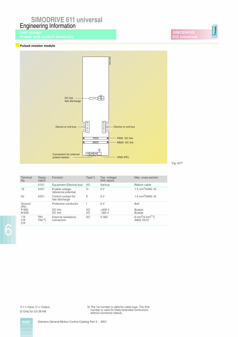
Siemens General Motion Control Catalog Part 3 · 20016/62
SIMODRIVE 611 universalEngineering Information
6
SIMODRIVE611 universal
■ Pulsed resistor module
1) I = Input; O = Output.
2) Only for O/I 28 kW.
3) The 1st number is valid for cable lugs. The 2nd number is valid for finely-stranded conductors without connector sleeve.
X351
X151
X221
3R2R1R
GM
C-5
048
M600
P600
5019
Device or unit busDevice or unit bus
P600 DC link
M600 DC link
DC linkfast discharge
Connectors for externalpulsed resistor GND (PE)
Fig. 6/77
TerminalNo.
Desig-nation
Function Type1) Typ. voltage/limit values
Max. cross-section
X151 Equipment (Device) bus I/O Various Ribbon cable
19 X221 Enable voltage, reference potential
O 0 V 1.5 mm2/AWG 16
50 X221 Control contact for fast discharge
E 0 V 1.5 mm2/AWG 16
Ground(PE)P 600M 600
Protective conductor
DC linkDC link
I
I/OI/O
0 V
+300 V–300 V
Bolt
BusbarBusbar
1 R2 R3 R
TR1TR2 2)
External resistanceconnection
I/O V 300 6 mm2/4 mm2 3)AWG 10/12
Unit designPower and control terminals
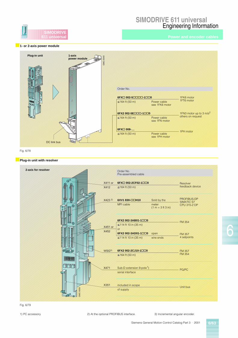
Siemens General Motion Control Catalog Part 3 · 2001 6/63
SIMODRIVE 611 universalEngineering Information
6
SIMODRIVE611 universal
■ 1- or 2-axis power module
■ Plug-in unit with resolver
GM
C-5
049
DC link bus
Fig. 6/78
Order No.
6FX@ 002-5@@@@-1@@0 1FK6 motor1FT6 motor
£164 ft (50 m) Power cable see 1FK6 motor
6FX2 002-5E@@@-1@@0 1FN3 motor up to 3 m/s2
others on request£164 ft (50 m) Power cable
see 1FN motor
6FX@ 008-...1PH motor
£164 ft (50 m) Power cable see 1PH motor
Plug-in unit 1-axispower module
GM
C-5
050
X411 or
X412
X423 2)
X451 or
X452
WSG3)
X471
X351
Fig. 6/79
Order No.Pre-assembled cable
6FX@ 002-2CF02-1@@0 Resolver feedback device
£164 ft (50 m)
6XV1 830-@@H10 Sold by the PROFIBUS-DPSIMATIC S7CPU 315-2 DPMPI cable meter
(1 m = 3 ft 3 in)
6FX2 002-3AB01-1@@0 FM 354£114 ft 10 in (35 m)
or
6FX2 002-3AD01-1@@0 open FM 3574 setpoints
£114 ft 10 in (35 m) wire ends
6FX2 002-2CJ10-1@@0 FM 357FM 354
£164 ft (50 m)
Sub-D extension 9-pole1)PG/PC
serial interface
included in scopeUnit bus
of supply
2-axis for resolver
1) PC accessory. 2) At the optional PROFIBUS interface. 3) Incremental angular encoder.
Power and encoder cables
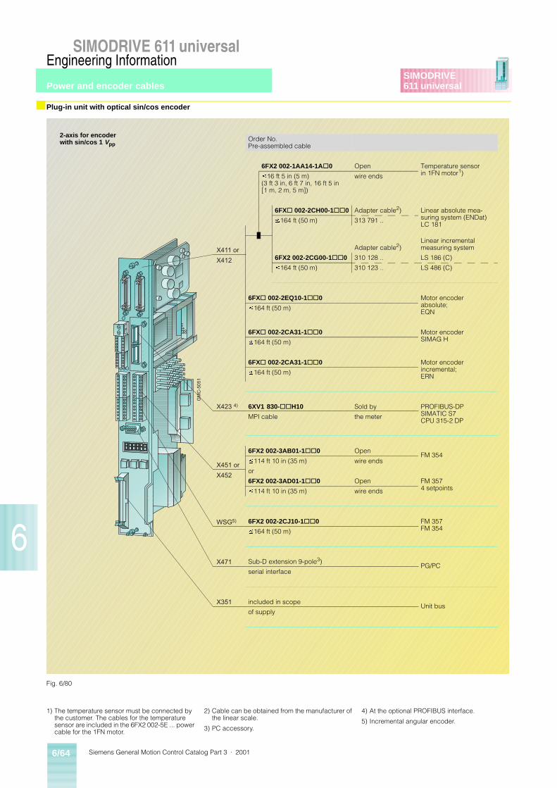
Siemens General Motion Control Catalog Part 3 · 20016/64
SIMODRIVE 611 universal
6
SIMODRIVE611 universal
Engineering Information
■ Plug-in unit with optical sin/cos encoder
GM
C-5
051
X411 or
X412
X423 4)
X451 or
X452
WSG5)
X471
X351
Fig. 6/80
Order No.Pre-assembled cable
6FX2 002-1AA14-1A@0 Open Temperature sensor in 1FN motor1)
£16 ft 5 in (5 m)(3 ft 3 in, 6 ft 7 in, 16 ft 5 in [1 m, 2 m, 5 m])
wire ends
6FX@ 002-2CH00-1@@0 Adapter cable2) Linear absolute mea-suring system (ENDat) LC 181
£164 ft (50 m) 313 791 ..
Adapter cable2)Linear incremental measuring system
6FX2 002-2CG00-1@@0 310 128 .. LS 186 (C)
£164 ft (50 m) 310 123 .. LS 486 (C)
6FX@ 002-2EQ10-1@@0 Motor encoder absolute; EQN
£164 ft (50 m)
6FX@ 002-2CA31-1@@0 Motor encoder SIMAG H
£164 ft (50 m)
6FX@ 002-2CA31-1@@0 Motor encoder incremental; ERN
£164 ft (50 m)
6XV1 830-@@H10 Sold by PROFIBUS-DPSIMATIC S7CPU 315-2 DP
MPI cable the meter
6FX2 002-3AB01-1@@0 OpenFM 354
£114 ft 10 in (35 m) wire ends
or
6FX2 002-3AD01-1@@0 Open FM 3574 setpoints
£114 ft 10 in (35 m) wire ends
6FX2 002-2CJ10-1@@0 FM 357FM 354
£164 ft (50 m)
Sub-D extension 9-pole3)PG/PC
serial interface
included in scopeUnit bus
of supply
2-axis for encoderwith sin/cos 1 Vpp
1) The temperature sensor must be connected by the customer. The cables for the temperature sensor are included in the 6FX2 002-5E ... power cable for the 1FN motor.
2) Cable can be obtained from the manufacturer of the linear scale.
3) PC accessory.
4) At the optional PROFIBUS interface.
5) Incremental angular encoder.
Power and encoder cables
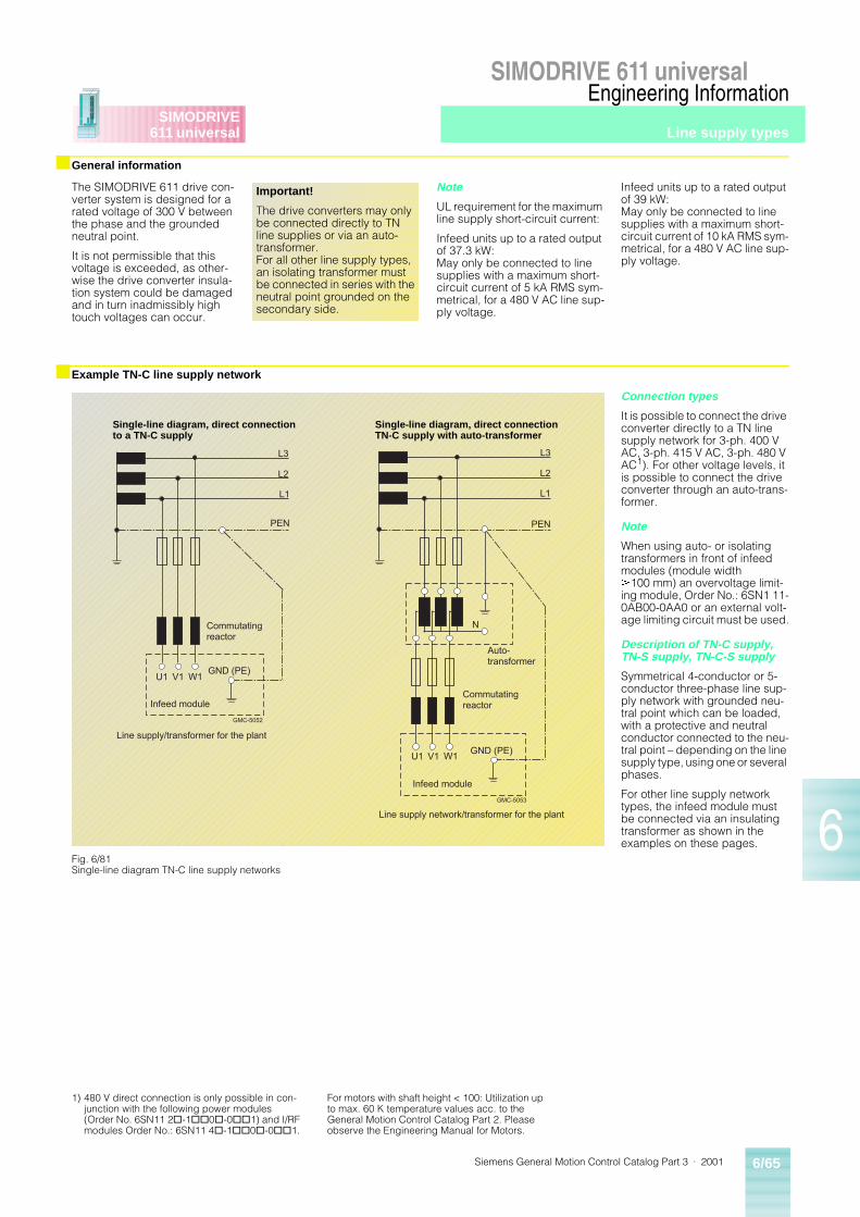
Siemens General Motion Control Catalog Part 3 · 2001 6/65
SIMODRIVE 611 universal
6
SIMODRIVE611 universal
Engineering Information
■ General information
■ Example TN-C line supply network
The SIMODRIVE 611 drive con-verter system is designed for a rated voltage of 300 V between the phase and the grounded neutral point.
It is not permissible that this voltage is exceeded, as other-wise the drive converter insula-tion system could be damaged and in turn inadmissibly high touch voltages can occur.
Note
UL requirement for the maximum line supply short-circuit current:
Infeed units up to a rated output of 37.3 kW:May only be connected to line supplies with a maximum short-circuit current of 5 kA RMS sym-metrical, for a 480 V AC line sup-ply voltage.
Infeed units up to a rated output of 39 kW:May only be connected to line supplies with a maximum short-circuit current of 10 kA RMS sym-metrical, for a 480 V AC line sup-ply voltage.
Connection types
It is possible to connect the drive converter directly to a TN line supply network for 3-ph. 400 V AC, 3-ph. 415 V AC, 3-ph. 480 V AC1). For other voltage levels, it is possible to connect the drive converter through an auto-trans-former.
Note
When using auto- or isolating transformers in front of infeed modules (module width ³100 mm) an overvoltage limit-ing module, Order No.: 6SN1 11-0AB00-0AA0 or an external volt-age limiting circuit must be used.
Description of TN-C supply, TN-S supply, TN-C-S supply
Symmetrical 4-conductor or 5-conductor three-phase line sup-ply network with grounded neu-tral point which can be loaded, with a protective and neutral conductor connected to the neu-tral point – depending on the line supply type, using one or several phases.
For other line supply network types, the infeed module must be connected via an insulating transformer as shown in the examples on these pages.
Important!
The drive converters may only be connected directly to TN line supplies or via an auto-transformer.For all other line supply types, an isolating transformer must be connected in series with the neutral point grounded on the secondary side.
L3
L2
L1
PEN
U1 V1 W1
Infeed module
GMC-5052
Commutatingreactor
GND (PE)
Line supply/transformer for the plant
L3
L2
L1
PEN
U1 V1 W1
Infeed module
GMC-5053
N
Commutatingreactor
GND (PE)
Line supply network/transformer for the plant
Auto-transformer
Fig. 6/81Single-line diagram TN-C line supply networks
Single-line diagram, direct connection to a TN-C supply
Single-line diagram, direct connection TN-C supply with auto-transformer
1) 480 V direct connection is only possible in con-junction with the following power modules (Order No. 6SN11 2@-1@@0@-0@@1) and I/RF modules Order No.: 6SN11 4@-1@@0@-0@@1.
For motors with shaft height < 100: Utilization up to max. 60 K temperature values acc. to the General Motion Control Catalog Part 2. Please observe the Engineering Manual for Motors.
Line supply types
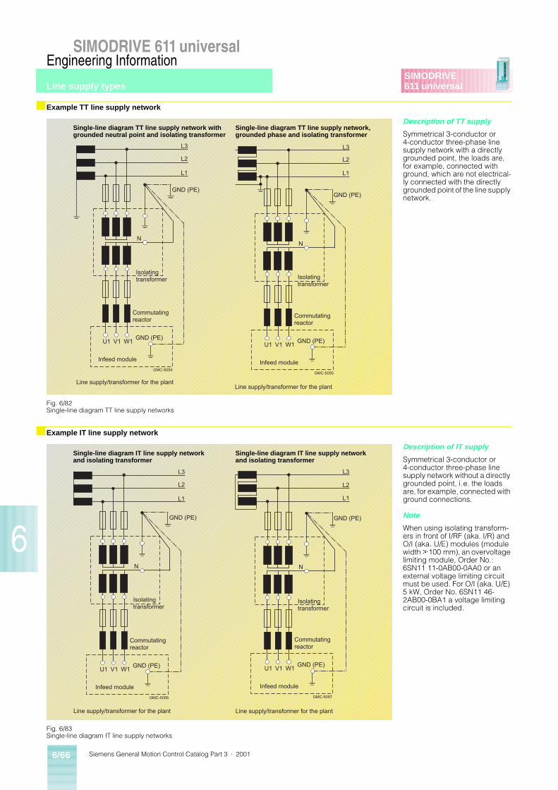
Siemens General Motion Control Catalog Part 3 · 20016/66
SIMODRIVE 611 universal
6
SIMODRIVE611 universal
Engineering Information
■ Example TT line supply network
■ Example IT line supply network
Description of TT supply
Symmetrical 3-conductor or 4-conductor three-phase line supply network with a directly grounded point, the loads are, for example, connected with ground, which are not electrical-ly connected with the directly grounded point of the line supply network.
Description of IT supply
Symmetrical 3-conductor or 4-conductor three-phase line supply network without a directly grounded point, i.e. the loads are, for example, connected with ground connections.
Note
When using isolating transform-ers in front of I/RF (aka. I/R) and O/I (aka. U/E) modules (module width ³100 mm), an overvoltage limiting module, Order No.: 6SN11 11-0AB00-0AA0 or an external voltage limiting circuit must be used. For O/I (aka. U/E) 5 kW, Order No. 6SN11 46-2AB00-0BA1 a voltage limiting circuit is included.
L3
L2
L1
GND (PE)
U1 V1 W1
Infeed module
GMC-5054
N
Commutatingreactor
GND (PE)
Line supply/transformer for the plant
Isolatingtransformer
L3
L2
L1
GND (PE)
U1 V1 W1
Infeed module
GMC-5055
N
Commutatingreactor
GND (PE)
Line supply/transformer for the plant
Isolatingtransformer
Fig. 6/82Single-line diagram TT line supply networks
Single-line diagram TT line supply network with grounded neutral point and isolating transformer
Single-line diagram TT line supply network, grounded phase and isolating transformer
L3
L2
L1
GND (PE)
U1 V1 W1
Infeed module
GMC-5056
N
Commutatingreactor
GND (PE)
Line supply/transformer for the plant
Isolatingtransformer
L3
L2
L1
GND (PE)
U1 V1 W1
Infeed module
GMC-5057
N
Commutatingreactor
GND (PE)
Line supply/transformer for the plant
Isolatingtransformer
Fig. 6/83Single-line diagram IT line supply networks
Single-line diagram IT line supply network and isolating transformer
Single-line diagram IT line supply network and isolating transformer
Line supply types
Siemens General Motion Control Catalog Part 3 · 2001 6/67
SIMODRIVE 611 universal
6
SIMODRIVE611 universal
Engineering Information
EMC stands for electromagnet-ic compatibility and, according to the definition of the EMC law, describes the “ability of a de-vice to function satisfactorily in an electromagnetic environ-ment without itself causing elec-tromagnetic interference which is unacceptable for other devic-es in this environment.” In order to ensure that the relevant EMC standards are complied with, the devices must demonstrate a sufficiently high immunity to in-terference, on the one hand, and interference emission must be limited to compatible values, on the other.
The product standard, EN 61 800-3, relevant to “vari-able-speed drives” describes the requirements for residential and industrial environments.
Immunity to interference
The units satisfy the require-ments of the EMC product stan-dard, EN 61 800-3, for industrial environments and thus the lower values regarding immunity to in-terference required by the resi-dential environment as well.
Interference emission and ra-dio-interference suppression
If converters are used in a resi-dential area, conducted interfer-ence or radiated interference must not exceed the limit values according to class “B1” in accor-dance with the European stan-dard EN 55 011.
A residential area in this sense is a connection, i.e. an outgoing section of a transformer, to which private households are also connected.
The EMC law requires that an industrial system as a whole is electromagnetically compati-ble with its environment.
In the case of units for use in in-dustrial environments, no limit values are defined for emitted interference.
If the SIMODRIVE units are to comply with limit values, the fol-lowing must be provided:
• Radio-interference suppres-sion filters, including the com-mutating reactors for reducing the cable-fed interference
• Screened cables for motor supply lines and signal lines for reducing electromagneti-cally emitted interference
• Compliance with the installa-tion guidelines.
In systems with SIMODRIVE units and other components, e.g. contactors, switches, eval-uation units, automation units etc., it must be ensured that no interference is emitted to the outside and also that the indi-vidual units do not cause inter-ference among themselves. In this respect, the measures de-scribed in the brochure, Design of Drives in Conformance with EMC Regulations contained in the Planning Guide should be followed.
The most important of these measures are summarized here:
• The components of a system must be housed in a cabinet which acts like a Faraday cage.
• Signal lines and motor supply cables must be screened. The screens must be connected to earth at both ends.
• Signal cables should be spa-tially separated (at least 8 in (20 cm)) from the power ca-bles. If necessary, screening plates are to be provided.
Type of interference Level of interference
Comments
Electrostatic Discharge (ESD) up to 12 V
Fast transient interference (bursts) up to 4 kV for power section
up to 2 kV for signal cables
Electromagnetic compatibility (EMC)
Siemens General Motion Control Catalog Part 3 · 20016/68
SIMODRIVE 611 universal
6
SIMODRIVE611 universal
Engineering Information
■ Overview
■ Encoders for position detection
Technology functions software of SIMODRIVE 611 universal Motion Control units
Operating mode speed/torque setpoint
• Closed-loop current and speed control
• Ramp-function generator• Optimizing the closed-loop
current and speed controller• Speed controller adaptation• Fixed speed setpoint (from
SW 3.1)• Monitoring functions• Limits
Positioning mode (from SW 2.1)
• Traversing range: ± 656.2 ft (± 200 m)
• Traversing speed: 0.001 up to 2000 m/min
• Acceleration/deceleration: 0.001 up to 999.999 m/s2
• Number of program blocks: 64• Encoder adaptation• Travel, velocity and accelera-
tion
• Closed-loop position control• Referencing• Adjustment for absolute motor
measuring systems• Parameter overview when
referencing/adjusting• Jogging• Programming traversing
blocks• Starting, interrupting and
aborting traversing blocks
Miscellaneous functions
• V/Hz operation (diagnostics function)
• V/Hz operation with induction motor (ARM)
• V/Hz operation with synchro-nous motor (SRM)
• Motor data optimization• Motor holding brake• Angular incremental encoder/
Xset interface (X461, X462)• Torque/power reduction via
terminal 24.x/20.x• Motor changeover for induc-
tion motors (from SW 2.4)• Parameter set changeover
SIMODRIVE 611 universal al-lows position detection directly via the motor encoder so that an additionally built-on encoder is not needed for position control. Only when it is necessary from a technological point of view can position detection take place by means of an additional external encoder. The types of encoder can be classified as absolute-value encoders.
Absolute-value encoders
can be divided up into two groups:
Single-turn encoders (two-pole resolver, optical sine/cosine en-coder) supply the absolute po-sition within a revolution.
If absolute positions have to be detected over several revolu-tions with a single-turn encoder (normal occurrence), referenc-ing is necessary as with the in-cremental encoder.
Multiturn encoders detect the position within a revolution and over a defined range (e.g. 4096 revolutions) and supply this val-ue when the system is restarted after a power failure. Referenc-ing is thus not necessary.
• Please note that with a 2-axis control board, it is not possi-ble to mix encoders with sin/cos 1 Vpp and resolvers.
• Third-party encoders can also be connected.
Notes
$ In practice, the resolution of the encoder must be higher than the requested positioning accuracy by a factor of 4 to 10. The levels of accuracy given in the table are only rough guide-lines.
% Resolver:
• In the case of multiple-pole resolvers, the resolution and accuracy is correspondingly higher.
• In the following cases, an ERN 1387 sine/cosine encoder should be used instead of a resolver:– for extreme requirements
regarding positioning accu-racy
– for extreme requirements regarding the dynamic re-sponse
– when printing indices are to be detected with a high de-gree of accuracy
– when smooth running char-acteristics are required at extremely low speeds under approx. 5 rpm.
Overview of the characteristics of the different encoders:
Encoder type Resolution(increments/revolution)
Achievable positioningaccuracy $(pulses/revolution)
Resolver % 4096 pulses/revwith 2-pole resolver
1024 pulses/revwith 2-pole resolver
Sine/cosine encoderERN 1387
65,535 pulses/rev 105 pulses/rev
Absolute-valueencoder EQN 1325
65,535 pulses/rev 105 pulses/rev
Technology
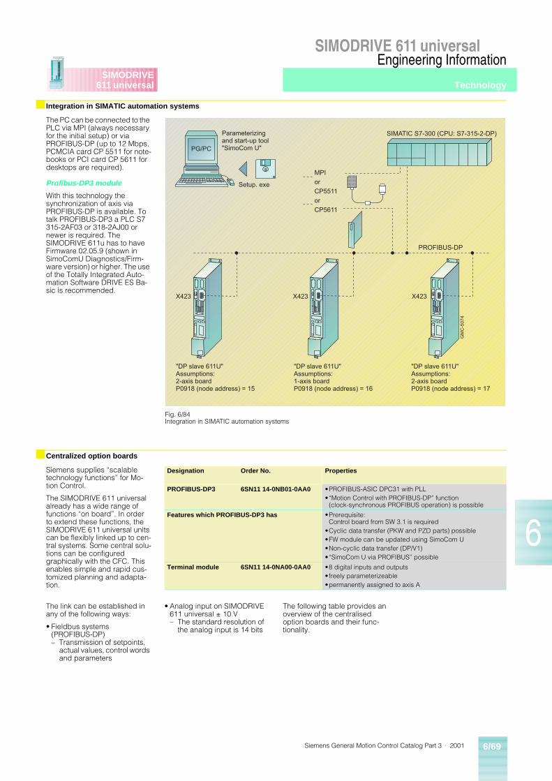
Siemens General Motion Control Catalog Part 3 · 2001 6/69
SIMODRIVE 611 universal
6
SIMODRIVE611 universal
Engineering Information
■ Integration in SIMATIC automation systems
■ Centralized option boards
The PC can be connected to the PLC via MPI (always necessary for the initial setup) or via PROFIBUS-DP (up to 12 Mbps, PCMCIA card CP 5511 for note-books or PCI card CP 5611 for desktops are required).
Profibus-DP3 module
With this technology the synchronization of axis via PROFIBUS-DP is available. To talk PROFIBUS-DP3 a PLC S7 315-2AF03 or 318-2AJ00 or newer is required. The SIMODRIVE 611u has to have Firmware 02.05.9 (shown in SimoComU Diagnostics/Firm-ware version) or higher. The use of the Totally Integrated Auto-mation Software DRIVE ES Ba-sic is recommended.
Siemens supplies “scalable technology functions” for Mo-tion Control.
The SIMODRIVE 611 universal already has a wide range of functions “on board”. In order to extend these functions, the SIMODRIVE 611 universal units can be flexibly linked up to cen-tral systems. Some central solu-tions can be configured graphically with the CFC. This enables simple and rapid cus-tomized planning and adapta-tion.
The link can be established in any of the following ways:
• Fieldbus systems(PROFIBUS-DP)– Transmission of setpoints,
actual values, control words and parameters
• Analog input on SIMODRIVE 611 universal ± 10 V– The standard resolution of
the analog input is 14 bits
The following table provides an overview of the centralised option boards and their func-tionality.
GM
C-5
074
SIMATIC S7-300 (CPU: S7-315-2-DP)Parameterizingand start-up tool"SimoCom U"
"DP slave 611U"Assumptions:2-axis boardP0918 (node address) = 15
X423 X423 X423
"DP slave 611U"Assumptions:1-axis boardP0918 (node address) = 16
"DP slave 611U"Assumptions:2-axis boardP0918 (node address) = 17
PROFIBUS-DP
MPIorCP5511orCP5611
PG/PC
Setup. exe
Fig. 6/84Integration in SIMATIC automation systems
Designation Order No. Properties
PROFIBUS-DP3 6SN11 14-0NB01-0AA0 •PROFIBUS-ASIC DPC31 with PLL•“Motion Control with PROFIBUS-DP” function
(clock-synchronous PROFIBUS operation) is possible
Features which PROFIBUS-DP3 has •Prerequisite:Control board from SW 3.1 is required
•Cyclic data transfer (PKW and PZD parts) possible•FW module can be updated using SimoCom U•Non-cyclic data transfer (DP/V1)•“SimoCom U via PROFIBUS” possible
Terminal module 6SN11 14-0NA00-0AA0 •8 digital inputs and outputs•freely parameterizeable•permanently assigned to axis A
Technology
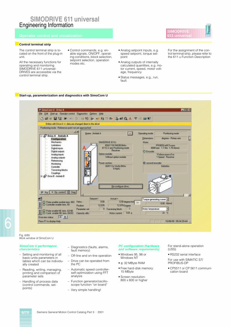
Siemens General Motion Control Catalog Part 3 · 20016/70
SIMODRIVE 611 universal
6
SIMODRIVE611 universal
Engineering Information
■ Control terminal strip
■ Start-up, parameterization and diagnostics with SimoCom U
The control terminal strip is lo-cated on the front of the plug-in unit.
All the necessary functions for operating and monitoring SIMODRIVE 611 universal-DRIVES are accessible via the control terminal strip.
• Control commands, e.g. en-able signals, ON/OFF, operat-ing conditions, block selection, setpoint selection, operation modes etc.
• Analog setpoint inputs, e.g. speed setpoint, torque set-point
• Analog outputs of internally calculated quantities, e.g. mo-tor current, speed, motor volt-age, frequency
• Status messages, e.g., run, fault.
For the assignment of the con-trol terminal strip, please refer to the 611 u Function Description
SimoCom U performance charcteristics
– Setting and monitoring of all basic-units parameters in tables which can be individu-ally created
– Reading, writing, managing, printing and comparison of parameter sets
– Handling of process data (control commands, set-points)
– Diagnostics (faults, alarms, fault memory)
– Off-line and on-line operation
– Drive can be operated from the PC
– Automatic speed controller-self-optimization using FFT analysis
– Function generator/oscillo-scope function “on board”
– Very simple handling!
PC configuration (hardware and software requirements)
• Windows 95, 98 or Windows NT
•³ 32 MByte RAM
• Free hard-disk memory:15 MByte
• Screen resolution:800 x 600 or higher
For stand-alone operation (USS)
• RS232 serial interface
For use with SIMATIC S7/PROFIBUS-DP
• CP5511 or CP 5611 communi-cation board
Fig. 6/85Work window of SimoCom U
Operator control and visualization
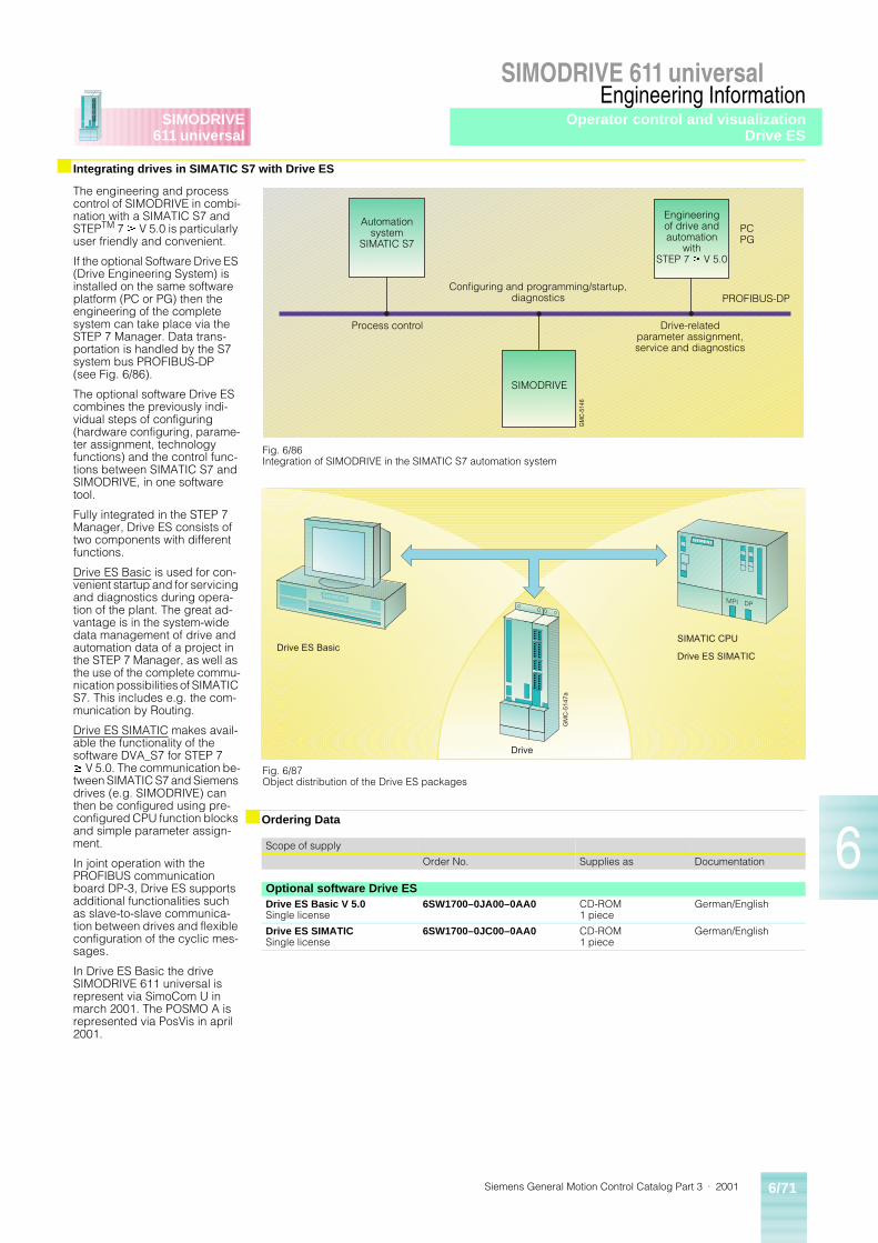
Siemens General Motion Control Catalog Part 3 · 2001 6/71
SIMODRIVE 611 universal
6
SIMODRIVE611 universal
Engineering Information
■ Integrating drives in SIMATIC S7 with Drive ES
The engineering and process control of SIMODRIVE in combi-nation with a SIMATIC S7 and STEPTM 7 ³ V 5.0 is particularly user friendly and convenient.
If the optional Software Drive ES (Drive Engineering System) is installed on the same software platform (PC or PG) then the engineering of the complete system can take place via the STEP 7 Manager. Data trans-portation is handled by the S7 system bus PROFIBUS-DP (see Fig. 6/86).
The optional software Drive ES combines the previously indi-vidual steps of configuring (hardware configuring, parame-ter assignment, technology functions) and the control func-tions between SIMATIC S7 and SIMODRIVE, in one software tool.
Fully integrated in the STEP 7 Manager, Drive ES consists of two components with different functions.
Drive ES Basic is used for con-venient startup and for servicing and diagnostics during opera-tion of the plant. The great ad-vantage is in the system-wide data management of drive and automation data of a project in the STEP 7 Manager, as well as the use of the complete commu-nication possibilities of SIMATIC S7. This includes e.g. the com-munication by Routing.
Drive ES SIMATIC makes avail-able the functionality of the software DVA_S7 for STEP 7 ³ V 5.0. The communication be-tween SIMATIC S7 and Siemens drives (e.g. SIMODRIVE) can then be configured using pre-configured CPU function blocks and simple parameter assign-ment.
In joint operation with the PROFIBUS communication board DP-3, Drive ES supports additional functionalities such as slave-to-slave communica-tion between drives and flexible configuration of the cyclic mes-sages.
In Drive ES Basic the drive SIMODRIVE 611 universal is represent via SimoCom U in march 2001. The POSMO A is represented via PosVis in april 2001.
■ Ordering Data
GM
C-5
146
Fig. 6/86Integration of SIMODRIVE in the SIMATIC S7 automation system
Automationsystem
SIMATIC S7
SIMODRIVE
Engineeringof drive andautomation
withSTEP 7 ³ V 5.0
Drive-relatedparameter assignment,service and diagnostics
Process control
Configuring and programming/startup,diagnostics PROFIBUS-DP
PCPG
Drive
GM
C-5
147a
Drive ES BasicSIMATIC CPU
Drive ES SIMATIC
Fig. 6/87Object distribution of the Drive ES packages
Scope of supply
Order No. Supplies as Documentation
Optional software Drive ESDrive ES Basic V 5.0Single license
6SW1700–0JA00–0AA0 CD-ROM1 piece
German/English
Drive ES SIMATICSingle license
6SW1700–0JC00–0AA0 CD-ROM1 piece
German/English
Operator control and visualizationDrive ES
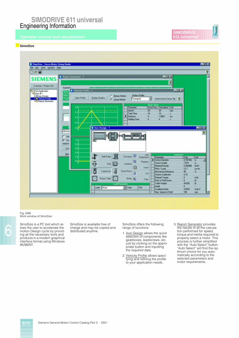
Siemens General Motion Control Catalog Part 3 · 20016/72
SIMODRIVE 611 universal
6
SIMODRIVE611 universal
Engineering Information
■ SimoSize
SimoSize is a PC tool which al-lows the user to accelerate the motion Design cycle by provid-ing all the necessary tools and products in a modern graphical interface format using Windows 95/98/NT.
SimoSize is available free of charge and may be copied and distributed anytime.
SimoSize offers the following range of functions:
1. Axis Design allows the quick selection of components like gearboxes, leadscrews, etc. just by clicking on the appro-priate button and inputting the required data.
2. Velocity Profile allows speci-fying and refining the profile to your application needs.
3. Report Generator provides the results of all the calcula-tion performed for speed, torque and inertia required to properly select a motor. This process is further simplified with the “Auto Select” button. “Auto Select” will find the op-timum choice for you auto-matically according to theselected parameters and motor requirements.
Fig. 6/88Work window of SimoSize
Operator control and visualization
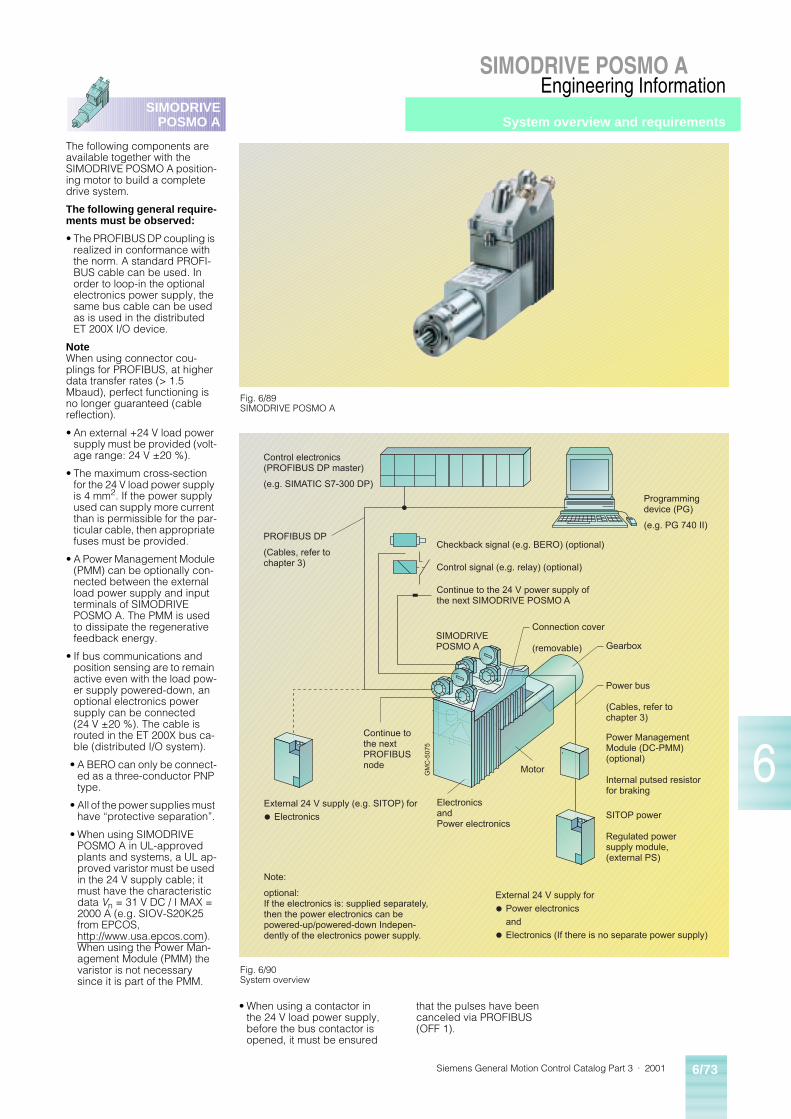
Siemens General Motion Control Catalog Part 3 · 2001 6/73
SIMODRIVE POSMO A
6
SIMODRIVEPOSMO A
Engineering Information
The following components are available together with the SIMODRIVE POSMO A position-ing motor to build a complete drive system.
The following general require-ments must be observed:
• The PROFIBUS DP coupling is realized in conformance with the norm. A standard PROFI-BUS cable can be used. In order to loop-in the optional electronics power supply, the same bus cable can be used as is used in the distributed ET 200X I/O device.
NoteWhen using connector cou-plings for PROFIBUS, at higher data transfer rates (> 1.5 Mbaud), perfect functioning is no longer guaranteed (cable reflection).
• An external +24 V load power supply must be provided (volt-age range: 24 V ±20 %).
• The maximum cross-section for the 24 V load power supply is 4 mm2. If the power supply used can supply more current than is permissible for the par-ticular cable, then appropriate fuses must be provided.
• A Power Management Module (PMM) can be optionally con-nected between the external load power supply and input terminals of SIMODRIVE POSMO A. The PMM is used to dissipate the regenerative feedback energy.
• If bus communications and position sensing are to remain active even with the load pow-er supply powered-down, an optional electronics power supply can be connected (24 V ±20 %). The cable is routed in the ET 200X bus ca-ble (distributed I/O system).
• A BERO can only be connect-ed as a three-conductor PNP type.
• All of the power supplies must have “protective separation”.
• When using SIMODRIVE POSMO A in UL-approved plants and systems, a UL ap-proved varistor must be used in the 24 V supply cable; it must have the characteristic data Vn = 31 V DC / I MAX = 2000 A (e.g. SIOV-S20K25 from EPCOS, http://www.usa.epcos.com). When using the Power Man-agement Module (PMM) the varistor is not necessary since it is part of the PMM.
System overview and requirements
• When using a contactor in the 24 V load power supply, before the bus contactor is opened, it must be ensured
that the pulses have been canceled via PROFIBUS (OFF 1).
Fig. 6/89SIMODRIVE POSMO A
GM
C-5
075
Control electronics(PROFIBUS DP master)
(e.g. SIMATIC S7-300 DP)
Programmingdevice (PG)
(e.g. PG 740 II)PROFIBUS DP
(Cables, refer tochapter 3)
SIMODRIVEPOSMO A
Checkback signal (e.g. BERO) (optional)
Control signal (e.g. relay) (optional)
Continue to the 24 V power supply ofthe next SIMODRIVE POSMO A
Connection cover
(removable) Gearbox
Power bus
(Cables, refer tochapter 3)
Power ManagementModule (DC-PMM)(optional)
Internal putsed resistorfor braking
SITOP power
Regulated powersupply module,(external PS)
ElectronicsandPower electronics
External 24 V supply for Power electronics and Electronics (If there is no separate power supply)
Continue tothe nextPROFIBUSnode
External 24 V supply (e.g. SITOP) for Electronics
Note:
optional:If the electronics is: supplied separately,then the power electronics can bepowered-up/powered-down Indepen-dently of the electronics power supply.
Motor
Fig. 6/90System overview
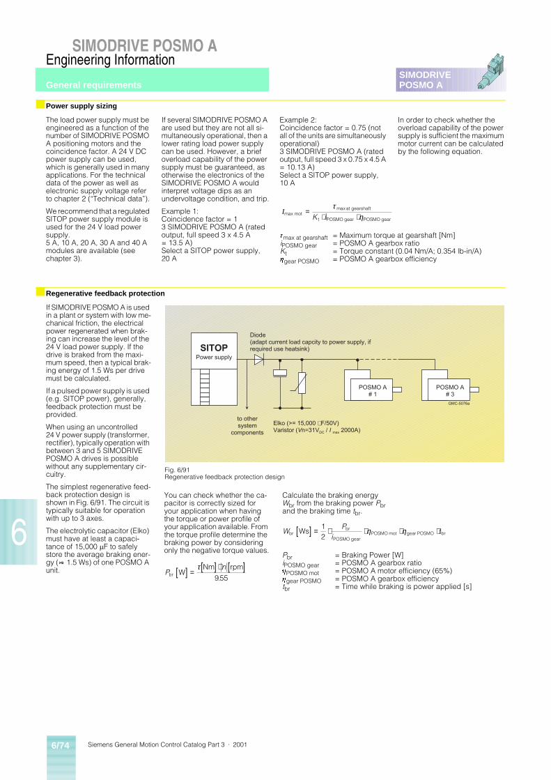
Siemens General Motion Control Catalog Part 3 · 20016/74
SIMODRIVE POSMO A
6
SIMODRIVEPOSMO A
Engineering Information
■ Power supply sizing
■ Regenerative feedback protection
The load power supply must be engineered as a function of the number of SIMODRIVE POSMO A positioning motors and the coincidence factor. A 24 V DC power supply can be used, which is generally used in many applications. For the technical data of the power as well as electronic supply voltage refer to chapter 2 (“Technical data”).
We recommend that a regulated SITOP power supply module is used for the 24 V load power supply.5 A, 10 A, 20 A, 30 A and 40 A modules are available (see chapter 3).
If several SIMODRIVE POSMO A are used but they are not all si-multaneously operational, then a lower rating load power supply can be used. However, a brief overload capability of the power supply must be guaranteed, as otherwise the electronics of the SIMODRIVE POSMO A would interpret voltage dips as an undervoltage condition, and trip.
Example 1:Coincidence factor = 13 SIMODRIVE POSMO A (rated output, full speed 3 x 4.5 A = 13.5 A)Select a SITOP power supply, 20 A
Example 2:Coincidence factor = 0.75 (not all of the units are simultaneously operational)3 SIMODRIVE POSMO A (rated output, full speed 3 x 0.75 x 4.5 A = 10.13 A)Select a SITOP power supply, 10 A
In order to check whether the overload capability of the power supply is sufficient the maximum motor current can be calculated by the following equation.
If SIMODRIVE POSMO A is used in a plant or system with low me-chanical friction, the electrical power regenerated when brak-ing can increase the level of the 24 V load power supply. If the drive is braked from the maxi-mum speed, then a typical brak-ing energy of 1.5 Ws per drive must be calculated.
If a pulsed power supply is used (e.g. SITOP power), generally, feedback protection must be provided.
When using an uncontrolled 24 V power supply (transformer, rectifier), typically operation with between 3 and 5 SIMODRIVE POSMO A drives is possible without any supplementary cir-cuitry.
The simplest regenerative feed-back protection design is shown in Fig. 6/91. The circuit is typically suitable for operation with up to 3 axes.
The electrolytic capacitor (Elko) must have at least a capaci-tance of 15,000 mF to safely store the average braking ener-gy (» 1.5 Ws) of one POSMO A unit.
tmax at gearshaft = Maximum torque at gearshaft [Nm]iPOSMO gear = POSMO A gearbox ratioKt = Torque constant (0.04 Nm/A; 0.354 lb-in/A)hgear POSMO = POSMO A gearbox efficiency
Imax motat gearshaft
t POSMO gear POSMO gear
=⋅ ⋅
τη
max
K i
POSMO A# 3
POSMO A# 1
SITOPPower supply
GMC-5076a
to other system
components
Diode(adapt current load capcity to power supply, ifrequired use heatsink)
Elko (>= 15,000 m F/50V)Varistor (Vn=31VDC / I max 2000A)
Fig. 6/91Regenerative feedback protection design
You can check whether the ca-pacitor is correctly sized for your application when having the torque or power profile of your application available. From the torque profile determine the braking power by considering only the negative torque values.
Pn
br WNm rpm[ ] = [ ] ⋅ [ ]τ
955.
Calculate the braking energy Wbr from the braking power Pbr and the braking time tbr.
Pbr = Braking Power [W]iPOSMO gear = POSMO A gearbox ratiohPOSMO mot = POSMO A motor efficiency (65%)hgear POSMO = POSMO A gearbox efficiencytbr = Time while braking is power applied [s]
WP
itbr
br
POSMO gearPOSMO mot gear POSMO brWs[ ] = ⋅ ⋅ ⋅ ⋅1
2η η
General requirements
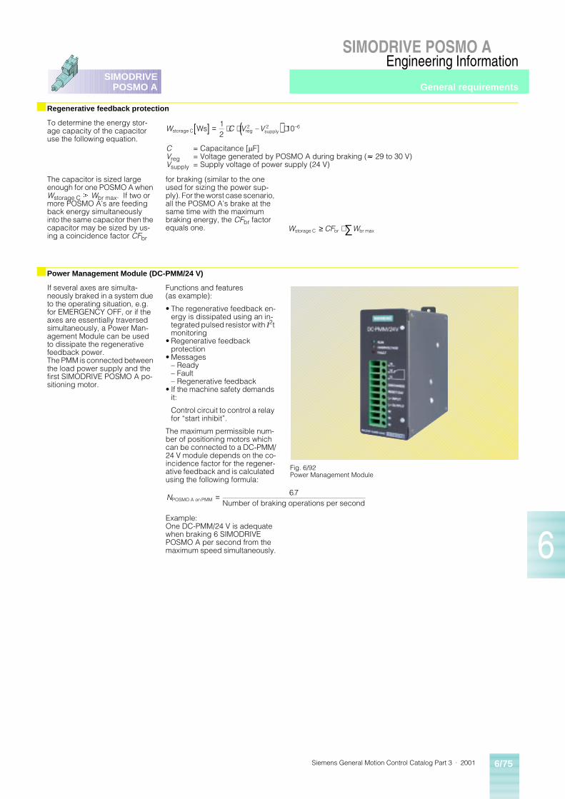
Siemens General Motion Control Catalog Part 3 · 2001 6/75
SIMODRIVE POSMO A
6
SIMODRIVEPOSMO A
Engineering Information
■ Regenerative feedback protection
■ Power Management Module (DC-PMM/24 V)
To determine the energy stor-age capacity of the capacitor use the following equation.
The capacitor is sized large enough for one POSMO A when Wstorage C ³ Wbr max. If two or more POSMO A’s are feeding back energy simultaneously into the same capacitor then the capacitor may be sized by us-ing a coincidence factor CFbr
for braking (similar to the one used for sizing the power sup-ply). For the worst case scenario, all the POSMO A’s brake at the same time with the maximum braking energy, the CFbr factor equals one.
If several axes are simulta-neously braked in a system due to the operating situation, e.g. for EMERGENCY OFF, or if the axes are essentially traversed simultaneously, a Power Man-agement Module can be used to dissipate the regenerative feedback power.The PMM is connected between the load power supply and the first SIMODRIVE POSMO A po-sitioning motor.
Functions and features (as example):
• The regenerative feedback en-ergy is dissipated using an in-tegrated pulsed resistor with I2t monitoring
• Regenerative feedback protection
• Messages– Ready– Fault– Regenerative feedback
• If the machine safety demands it:
Control circuit to control a relay for “start inhibit”.
The maximum permissible num-ber of positioning motors which can be connected to a DC-PMM/24 V module depends on the co-incidence factor for the regener-ative feedback and is calculated using the following formula:
Example:One DC-PMM/24 V is adequate when braking 6 SIMODRIVE POSMO A per second from the maximum speed simultaneously.
C = Capacitance [mF]Vreg = Voltage generated by POSMO A during braking (» 29 to 30 V)Vsupply = Supply voltage of power supply (24 V)
W C V Vstorage C reg supplyWs[ ] = ⋅ ⋅ ( ) ⋅12
102 2– –6
W CF Wstorage C br br≥ ⋅ ∑ max
NPOSMO A on PMM Number of braking operations per second= 67.
Fig. 6/92Power Management Module
General requirements
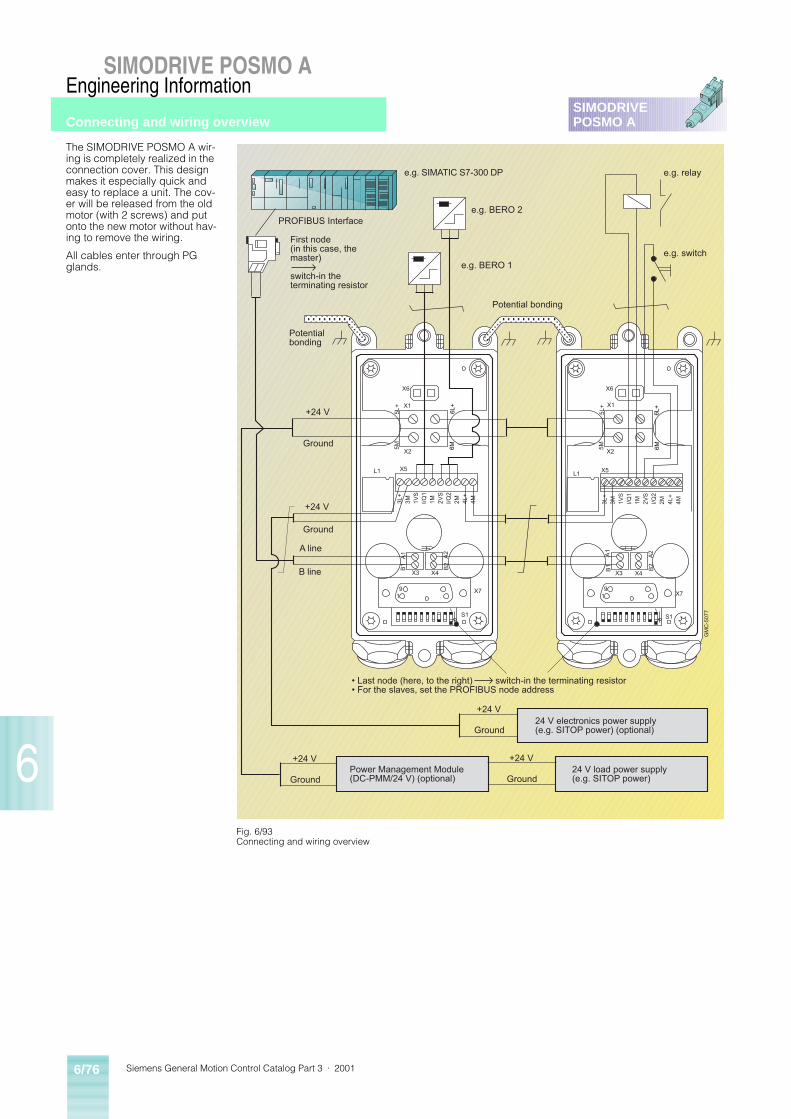
Siemens General Motion Control Catalog Part 3 · 20016/76
SIMODRIVE POSMO A
6
SIMODRIVEPOSMO A
Engineering Information
The SIMODRIVE POSMO A wir-ing is completely realized in the connection cover. This design makes it especially quick and easy to replace a unit. The cov-er will be released from the old motor (with 2 screws) and put onto the new motor without hav-ing to remove the wiring.
All cables enter through PG glands.
X6
X1
X2
5L+
5M
6L+
6M
X5L1
3L+
3M 1VS
I/Q1
1M 2VS
I/Q2
2M 4L+
4M
A1
B1
A2
B2
X3 X4
X7
S1
91
GM
C-5
077
X6
X1
X2
5L+
5M
6L+
6M
X5L1
3L+
3M 1VS
I/Q1
1M 2VS
I/Q2
2M 4L+
4M
A1
B1
A2
B2
X3 X4
X7
S1
91
� Last node (here, to the right) switch-in the terminating resistor� For the slaves, set the PROFIBUS node address
+24 V
Ground
+24 V
Ground
+24 V
Ground
+24 V
Ground
+24 V
Ground
A line
B line
e.g. SIMATIC S7-300 DP
PROFIBUS Interfacee.g. BERO 2
e.g. BERO 1
First node(in this case, themaster)
switch-in theterminating resistor
Potentialbonding
Potential bonding
e.g. relay
e.g. switch
Power Management Module(DC-PMM/24 V) (optional)
24 V load power supply(e.g. SITOP power)
24 V electronics power supply(e.g. SITOP power) (optional)
Fig. 6/93Connecting and wiring overview
Connecting and wiring overview
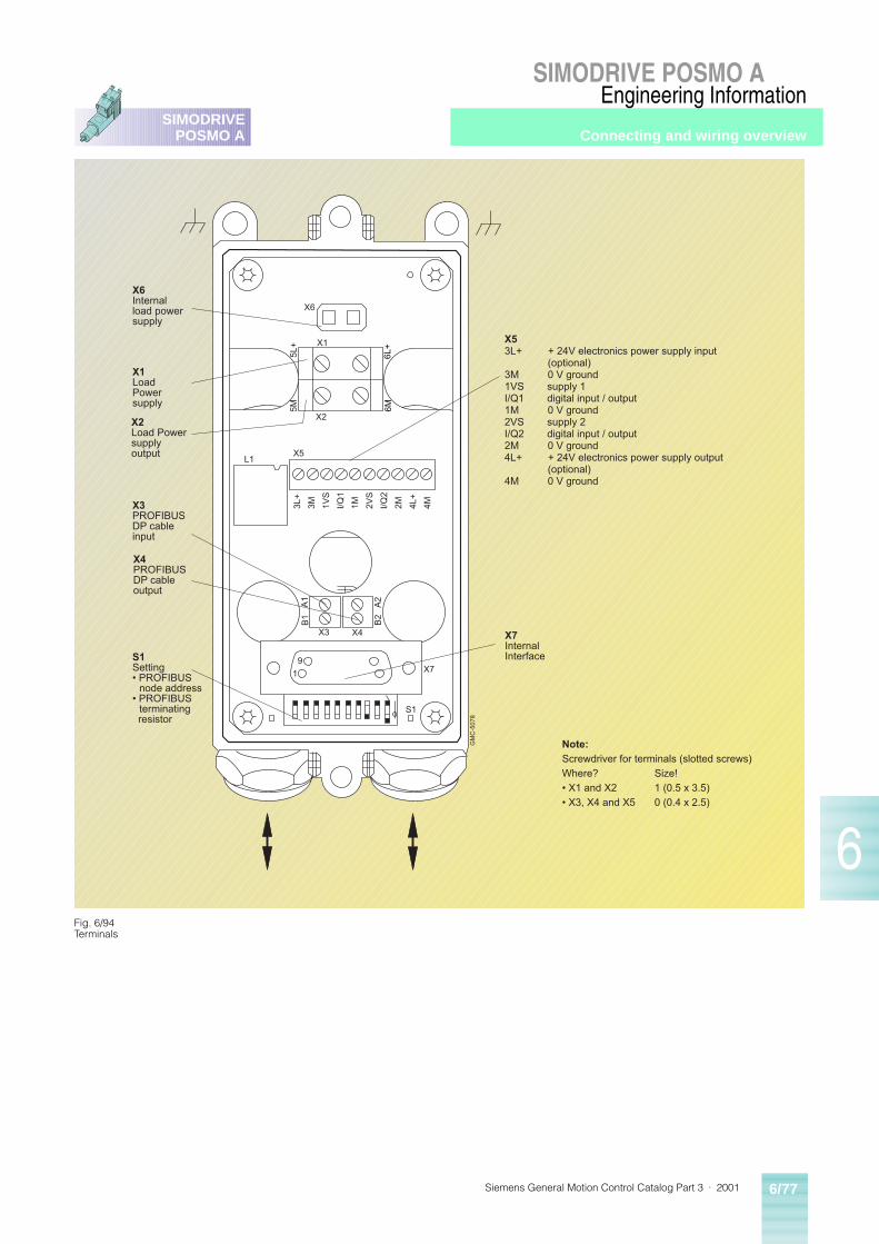
Siemens General Motion Control Catalog Part 3 · 2001 6/77
SIMODRIVE POSMO A
6
SIMODRIVEPOSMO A
Engineering Information
X6
X1
X2
5L+
5M
6L+
6M
X5L1
3L+
3M 1VS
I/Q1
1M 2VS
I/Q2
2M 4L+
4M
A1
B1
A2
B2
X3 X4
X7
S1
91
X6Internalload powersupply
X1LoadPowersupply
X3PROFIBUSDP cableinput
S1Setting� PROFIBUS
node address� PROFIBUS
terminating resistor
X2Load Powersupplyoutput
X4PROFIBUSDP cableoutput
X7InternalInterface
X53L+ + 24V electronics power supply input (optional)3M 0 V ground1VS supply 1I/Q1 digital input / output1M 0 V ground2VS supply 2I/Q2 digital input / output2M 0 V ground4L+ + 24V electronics power supply output (optional)4M 0 V ground
Note:Screwdriver for terminals (slotted screws)Where? Size!� X1 and X2 1 (0.5 x 3.5)� X3, X4 and X5 0 (0.4 x 2.5)
GM
C-5
078
Fig. 6/94Terminals
Connecting and wiring overview
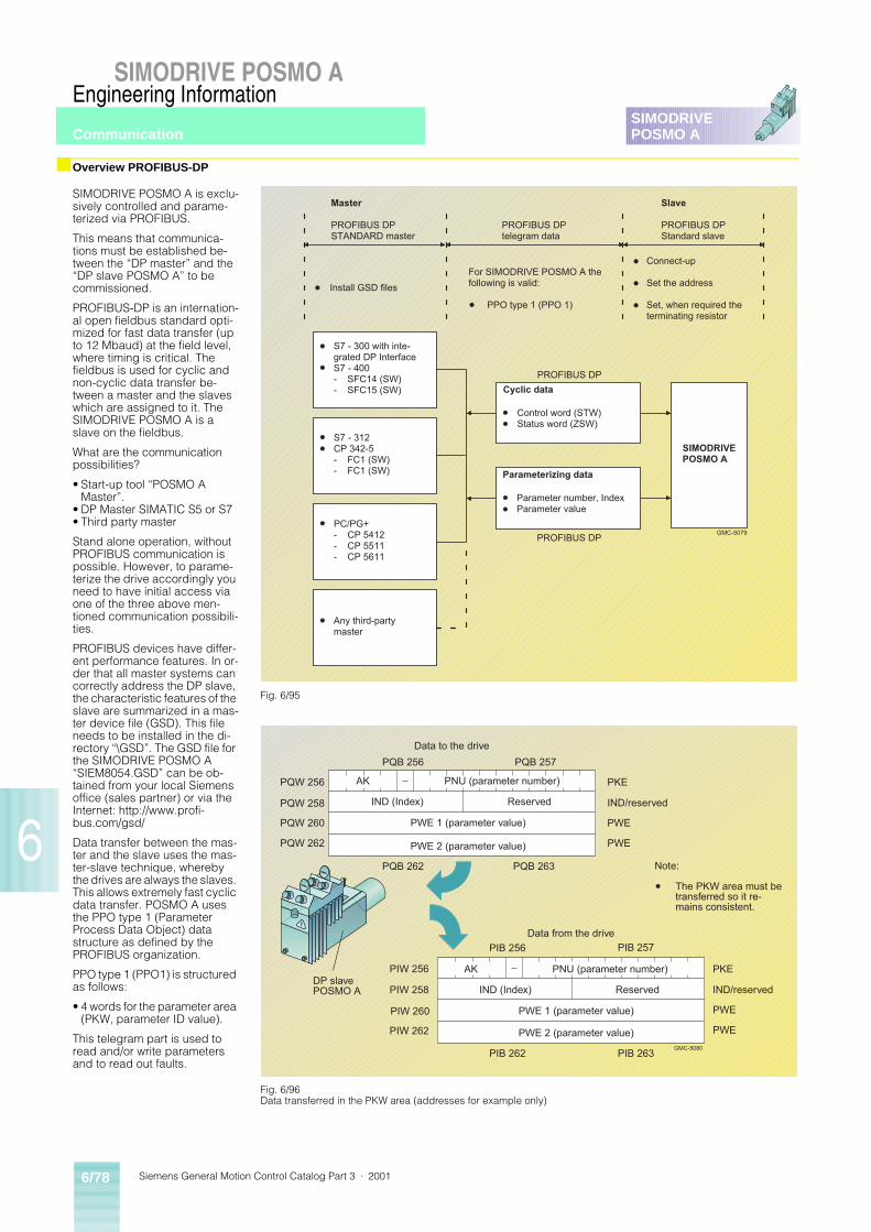
Siemens General Motion Control Catalog Part 3 · 20016/78
SIMODRIVE POSMO A
6
SIMODRIVEPOSMO A
Engineering Information
■ Overview PROFIBUS-DP
SIMODRIVE POSMO A is exclu-sively controlled and parame-terized via PROFIBUS.
This means that communica-tions must be established be-tween the “DP master” and the “DP slave POSMO A” to be commissioned.
PROFIBUS-DP is an internation-al open fieldbus standard opti-mized for fast data transfer (up to 12 Mbaud) at the field level, where timing is critical. The fieldbus is used for cyclic and non-cyclic data transfer be-tween a master and the slaves which are assigned to it. The SIMODRIVE POSMO A is a slave on the fieldbus.
What are the communication possibilities?
• Start-up tool “POSMO A Master”.
• DP Master SIMATIC S5 or S7• Third party master
Stand alone operation, without PROFIBUS communication is possible. However, to parame-terize the drive accordingly you need to have initial access via one of the three above men-tioned communication possibili-ties.
PROFIBUS devices have differ-ent performance features. In or-der that all master systems can correctly address the DP slave, the characteristic features of the slave are summarized in a mas-ter device file (GSD). This file needs to be installed in the di-rectory “\GSD”. The GSD file for the SIMODRIVE POSMO A “SIEM8054.GSD” can be ob-tained from your local Siemens office (sales partner) or via the Internet: http://www.profi-bus.com/gsd/
Data transfer between the mas-ter and the slave uses the mas-ter-slave technique, whereby the drives are always the slaves. This allows extremely fast cyclic data transfer. POSMO A uses the PPO type 1 (Parameter Process Data Object) data structure as defined by the PROFIBUS organization.
PPO type 1 (PPO1) is structured as follows:
• 4 words for the parameter area (PKW, parameter ID value).
This telegram part is used to read and/or write parameters and to read out faults.
GMC-5079
S7 - 300 with inte-grated DP InterfaceS7 - 400- SFC14 (SW)- SFC15 (SW)
S7 - 312CP 342-5- FC1 (SW)- FC1 (SW)
PC/PG+- CP 5412- CP 5511- CP 5611
Any third-partymaster
Control word (STW)Status word (ZSW)
Cyclic data
Parameter number, IndexParameter value
Parameterizing data
SIMODRIVEPOSMO A
PROFIBUS DP
PROFIBUS DP
Master
PROFIBUS DPSTANDARD master
PROFIBUS DPtelegram data
Slave
PROFIBUS DPStandard slave
Install GSD files
For SIMODRIVE POSMO A thefollowing is valid:
PPO type 1 (PPO 1)
Connect-up
Set the address
Set, when required theterminating resistor
Fig. 6/96Data transferred in the PKW area (addresses for example only)
Fig. 6/95
GMC-5080
PQB 256 PQB 257
PQB 262 PQB 263
AK PNU (parameter number)
IND (Index) Reserved
PKE
IND/reserved
PWE
PWE
PQW 256
PQW 260
PQW 262
PQW 258
PWE 1 (parameter value)
PWE 2 (parameter value)
AK PNU (parameter number)
IND (Index) Reserved
PWE 1 (parameter value)
PWE 2 (parameter value)
PKE
IND/reserved
PWE
PWE
Note:
The PKW area must betransferred so it re-mains consistent.
Data to the drive
PIB 256
PIW 256DP slavePOSMO A
Data from the drive
PIW 258
PIW 260
PIW 262
PIB 262 PIB 263
PIB 257
Communication
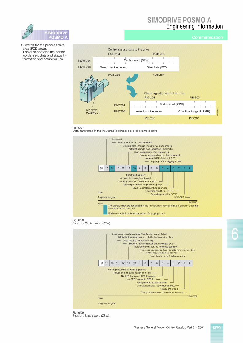
Siemens General Motion Control Catalog Part 3 · 2001 6/79
SIMODRIVE POSMO A
6
SIMODRIVEPOSMO A
Engineering Information
• 2 words for the process data area (PZD area). This area contains the control words, setpoints and status in-formation and actual values.
Fig. 6/98Structure Control Word (STW)
Fig. 6/97Data transferred in the PZD area (addresses are for example only)
Fig. 6/99Structure Status Word (ZSW)
GM
C-5
103
Control signals, data to the drive
PQB 264 PQB 265
PQB 266 PQB 267
PQW 266
Control word (STW)
Select block number Start byte (STB)
PIB 265
PIB 266 PIB 267
PQW 264
PIW 266
PIW 264
Status signals, data to the drive
Status word (ZSW)
Actual block number Checkback signal (RMB)DP slavePOSMO A
PIB 264
Bit 15 14 13 12 11 10 9 8 7 6 5 4 3 2 1 0
GMC-5082Note:
1 signal / 0 signal
Warning effective / no warning present
Power-on inhibit / no power-on inhibit
No OFF 3 present / OFF 3 present
No OFF 2 present / OFF 2 present
Fault present / no fault present
Operation enabled / operation inhibited
Ready or no fault
Ready to power-up / not ready to power-up
Load power supply available / load power supply failed
Within the traversing block / outside the traversing block
Drive moving / drive stationarySetpoint / traversing task acknowledged (edge)
Reference point set / no reference point set
Reference position reached / outside reference positionControl requested / local control
No following error / following error
Bit 15 14 13 12 11 9 8 7 6 5 4 3 2 1 0
GMC-5081
10
The signals which are designated in this fashion, must have at least a 1 signal in order thatthe motor can be operated.
Furthermore, bit 8 or 9 must be set to 1 for jogging 1 or 2.
Note:
Reset fault memory
Activate traversing task (edge)
Operating condition / intermediate stop
Operating condition for positioning/stop
Enable operation / inhibit operation
Operating condition / OFF 3
Operating condition / OFF 2
ON / OFF 1
Reserved
Read-in enable / no read-in enable
External block change / no external block changeAutomatic single block operation / automatic
Start referencing / stop referencing
Control requested / no control requestedJogging 2 ON / Jogging 2 OFF
Jogging 1 ON / Jogging 1 OFF
Note:
1 signal / 0 signal
Communication
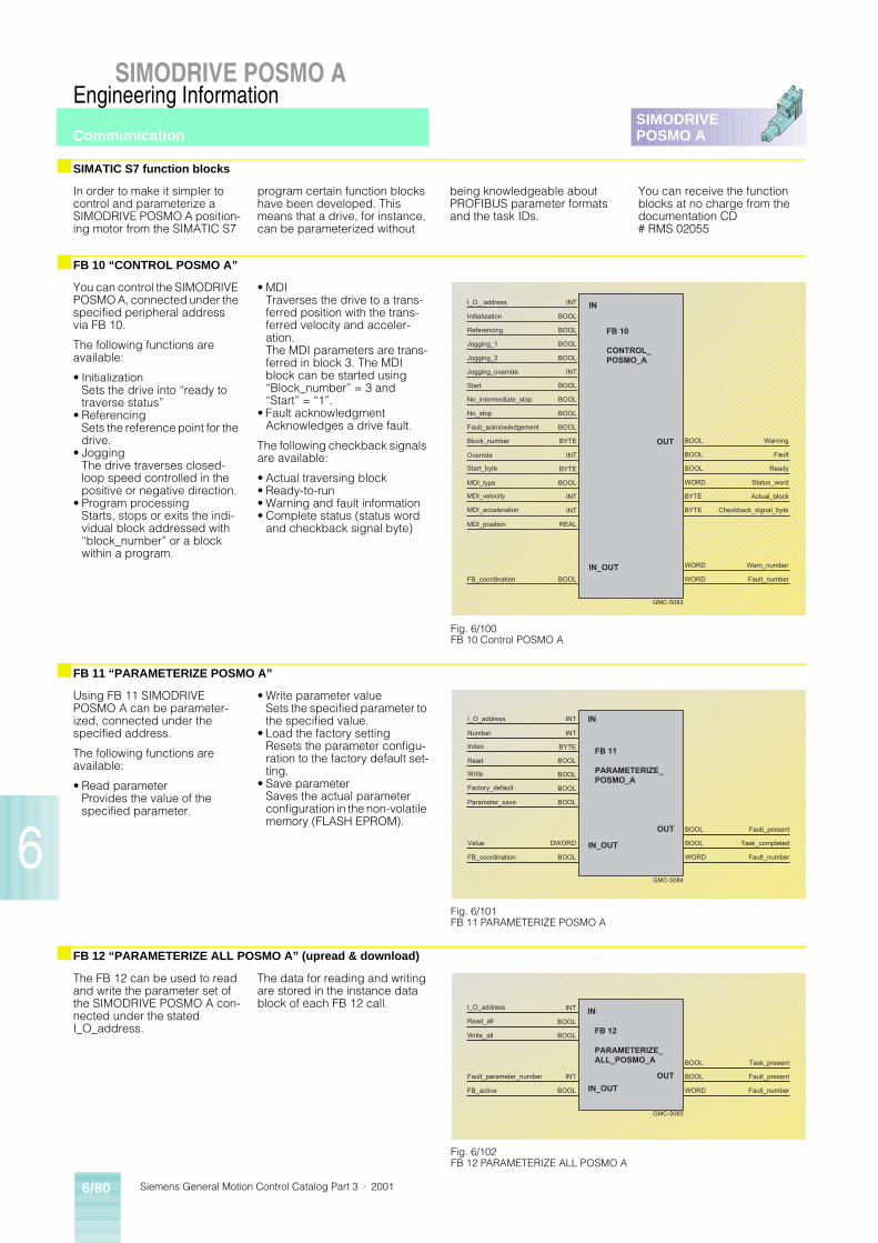
Siemens General Motion Control Catalog Part 3 · 20016/80
SIMODRIVE POSMO A
6
SIMODRIVEPOSMO A
Engineering Information
■ SIMATIC S7 function blocks
■ FB 10 “CONTROL POSMO A”
■ FB 11 “PARAMETERIZE POSMO A”
■ FB 12 “PARAMETERIZE ALL POSMO A” (upread & download)
In order to make it simpler to control and parameterize a SIMODRIVE POSMO A position-ing motor from the SIMATIC S7
program certain function blocks have been developed. This means that a drive, for instance, can be parameterized without
being knowledgeable about PROFIBUS parameter formats and the task IDs.
You can receive the function blocks at no charge from the documentation CD # RMS 02055
You can control the SIMODRIVE POSMO A, connected under the specified peripheral address via FB 10.
The following functions are available:
• InitializationSets the drive into “ready to traverse status”
• ReferencingSets the reference point for the drive.
• JoggingThe drive traverses closed-loop speed controlled in the positive or negative direction.
• Program processingStarts, stops or exits the indi-vidual block addressed with “block_number” or a block within a program.
• MDITraverses the drive to a trans-ferred position with the trans-ferred velocity and acceler-ation.The MDI parameters are trans-ferred in block 3. The MDI block can be started using “Block_number” = 3 and “Start” = “1”.
• Fault acknowledgmentAcknowledges a drive fault.
The following checkback signals are available:
• Actual traversing block• Ready-to-run• Warning and fault information• Complete status (status word
and checkback signal byte)
Using FB 11 SIMODRIVE POSMO A can be parameter-ized, connected under the specified address.
The following functions are available:
• Read parameterProvides the value of the specified parameter.
• Write parameter valueSets the specified parameter to the specified value.
• Load the factory settingResets the parameter configu-ration to the factory default set-ting.
• Save parameterSaves the actual parameter configuration in the non-volatile memory (FLASH EPROM).
The FB 12 can be used to read and write the parameter set of the SIMODRIVE POSMO A con-nected under the stated I_O_address.
The data for reading and writing are stored in the instance data block of each FB 12 call.
IN
FB 10
CONTROL_POSMO_A
OUT
IN_OUT
GMC-5083
I_O_ address
Initialization
Referencing
Jogging_1
Jogging_2
Jogging_override
Start
No_intermediate_stop
No_stop
Fault_acknowledgement
Block_number
Override
Start_byte
MDI_type
MDI_velocity
MDI_acceleration
MDI_position
FB_coordination
INT
BOOL
BOOL
BOOL
BOOL
INT
BOOL
BOOL
BOOL
BOOL
BYTE
INT
BYTE
BOOL
INT
INT
REAL
BOOL
BOOL
BOOL
BOOL
WORD
BYTE
BYTE
WORD
WORD
Warning
Fault
Ready
Status_word
Actual_block
Checkback_signal_byte
Warn_number
Fault_number
Fig. 6/100FB 10 Control POSMO A
IN
FB 11
PARAMETERIZE_POSMO_A
OUT
IN_OUT
GMC-5084
I_O_address
Number
Index
Read
Write
Factory_default
Parameter_save
FB_coordination
Value
INT
INT
BYTE
BOOL
BOOL
BOOL
BOOL
BOOL
DWORD Task_completed
Fault_number
Fault_present
BOOL
WORD
BOOL
Fig. 6/101FB 11 PARAMETERIZE POSMO A
IN
FB 12
PARAMETERIZE_ALL_POSMO_A
OUT
IN_OUT
GMC-5085
I_O_address
Read_all
Write_all
FB_active
Fault_parameter_number
INT
BOOL
BOOL
BOOL
INT Fault_present
Fault_number
Task_present
BOOL
WORD
BOOL
Fig. 6/102FB 12 PARAMETERIZE ALL POSMO A
Communication
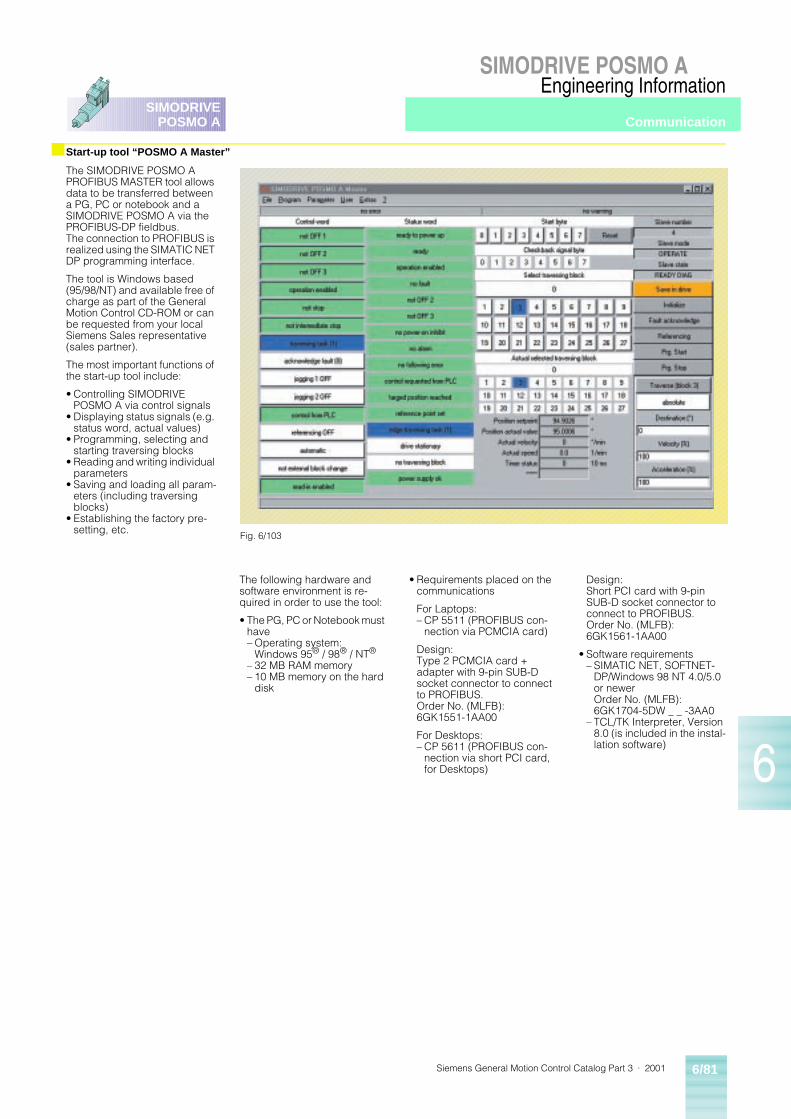
Siemens General Motion Control Catalog Part 3 · 2001 6/81
SIMODRIVE POSMO A
6
SIMODRIVEPOSMO A
Engineering Information
Communication
The SIMODRIVE POSMO A PROFIBUS MASTER tool allows data to be transferred between a PG, PC or notebook and a SIMODRIVE POSMO A via the PROFIBUS-DP fieldbus.The connection to PROFIBUS is realized using the SIMATIC NET DP programming interface.
The tool is Windows based (95/98/NT) and available free of charge as part of the General Motion Control CD-ROM or can be requested from your local Siemens Sales representative (sales partner).
The most important functions of the start-up tool include:
• Controlling SIMODRIVE POSMO A via control signals
• Displaying status signals (e.g. status word, actual values)
• Programming, selecting and starting traversing blocks
• Reading and writing individual parameters
• Saving and loading all param-eters (including traversing blocks)
• Establishing the factory pre-setting, etc.
The following hardware and software environment is re-quired in order to use the tool:
• The PG, PC or Notebook must have– Operating system:
Windows 95® / 98® / NT®
– 32 MB RAM memory– 10 MB memory on the hard
disk
• Requirements placed on the communications
For Laptops:– CP 5511 (PROFIBUS con-
nection via PCMCIA card)
Design:Type 2 PCMCIA card + adapter with 9-pin SUB-D socket connector to connect to PROFIBUS.Order No. (MLFB): 6GK1551-1AA00
For Desktops:– CP 5611 (PROFIBUS con-
nection via short PCI card, for Desktops)
Design:Short PCI card with 9-pin SUB-D socket connector to connect to PROFIBUS.Order No. (MLFB): 6GK1561-1AA00
• Software requirements– SIMATIC NET, SOFTNET-
DP/Windows 98 NT 4.0/5.0 or newerOrder No. (MLFB): 6GK1704-5DW _ _ -3AA0
– TCL/TK Interpreter, Version 8.0 (is included in the instal-lation software)
Fig. 6/103
■Start-up tool “POSMO A Master”

Siemens General Motion Control Catalog Part 3 · 20016/82
SIMODRIVE POSMO A
6
SIMODRIVEPOSMO A
Engineering Information
■ Traversing blocks and programs
For SIMODRIVE POSMO A, there are a total of 27 traversing blocks available. The compo-nents of each traversing block consists of:
• Program control word (PSW) allows to specify motion type (speed or position controlled), positioning type (absolute or relative), timer type (for timer operations in program blocks), traversing type (path or precise stop controlled), etc.
• Target position (mm, degrees or inch)
• Velocity value (0 to 100%)
• Acceleration value (0 to 100%)
• Timer value (0.01 to 10,000 s)
• Signaling positionWhen passing a specified po-sition, the bits specified in the position mask are set and sig-naled to the master via the checkback signal byte.
• Start signalsThe traversing block starts as soon as, in addition to the stan-dard enable signals (OFF1, OFF2, etc.), all of the config-ured bits of the start byte have been set. If one of the bits is withdrawn traversing stops and the block is ended.Specified bits can also be acti-vated when a traversing block starts. Bits are reset at the end of the block.
• Stop and positioning signalsSpecified bits can be activated at the end of a traversing block, they are automatically reset at the start of a new traversing block.Specified bits can be activated when passing the specified signaling position. The position feedback bits are reset when starting a new traversing block.
Traversing blocks 1 and 2 are reserved for jogging. Traversing blocks 3 to 27 can either be ex-ecuted as single blocks or be combined to form program blocks. Single blocks must be individually selected and start-ed. A program is started by se-lecting and starting a block within the program, the addi-tional blocks are then automati-cally executed as programmed.
■ Operating modes
Jogging mode
Traversing blocks 1 and 2 are reserved for jogging. They are executed by setting the appro-priate bit in the control word (see control word structure). After the signal has been with-drawn the block is stopped.
Manual Data Input (MDI)
For SIMODRIVE POSMO A, MDI operation is replaced by selecting a single traversing block. New coordinates are programmed by overwriting one of the traversing blocks and then transferred at the next start.
Automatic
In the “automatic mode”, tra-versing blocks and programs can be selected, started and their behavior significantly in-fluenced via the interface. By starting the first traversing block of a program all the sub-sequent following traversing blocks within this program will be automatically executed.
SIMODRIVE POSMO A features
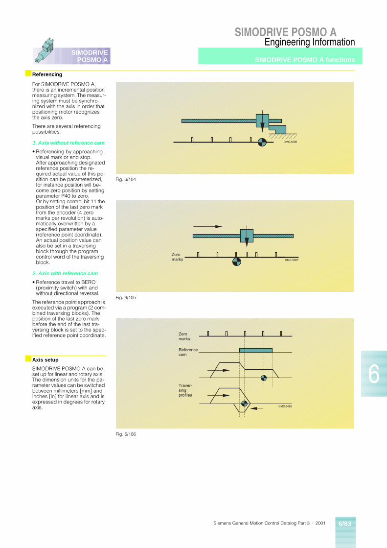
Siemens General Motion Control Catalog Part 3 · 2001 6/83
SIMODRIVE POSMO A
6
SIMODRIVEPOSMO A
Engineering Information
■ Referencing
For SIMODRIVE POSMO A, there is an incremental position measuring system. The measur-ing system must be synchro-nized with the axis in order that positioning motor recognizes the axis zero.
There are several referencing possibilities:
1. Axis without reference cam
• Referencing by approaching visual mark or end stop.After approaching designated reference position the re-quired actual value of this po-sition can be parameterized, for instance position will be-come zero position by setting parameter P40 to zero.Or by setting control bit 11 the position of the last zero mark from the encoder (4 zero marks per revolution) is auto-matically overwritten by a specified parameter value (reference point coordinate).An actual position value can also be set in a traversing block through the program control word of the traversing block.
2. Axis with reference cam
• Reference travel to BERO (proximity switch) with and without directional reversal.
The reference point approach is executed via a program (2 com-bined traversing blocks). The position of the last zero mark before the end of the last tra-versing block is set to the spec-ified reference point coordinate.
■ Axis setup
SIMODRIVE POSMO A can be set up for linear and rotary axis. The dimension units for the pa-rameter values can be switched between millimeters [mm] and inches [in] for linear axis and is expressed in degrees for rotary axis.
Fig. 6/106
Fig. 6/104
Fig. 6/105
GMC-5086
GMC-5087
Zeromarks
GMC-5088
Zeromarks
Referencecam
Traver-singprofiles
SIMODRIVE POSMO A functions
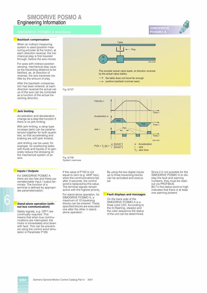
Siemens General Motion Control Catalog Part 3 · 20016/84
SIMODRIVE POSMO A
6
SIMODRIVEPOSMO A
Engineering Information
SIMODRIVE POSMO A functions
■ Backlash compensation
When an indirect measuring system is used (position mea-suring encoder at the motor), at each direction reversal, the me-chanical play is first traveled through, before the axis moves.
For axes with indirect position sensing, mechanical play caus-es the traversing distance to be falsified, as, at direction of reversal, the axis traverses too little by the amount of play.
After the backlash compensa-tion has been entered, at each direction reversal the actual val-ue of the axis can be corrected as a function of the actual tra-versing direction.
■ Jerk limiting
Acceleration and deceleration change as a step-like function if there is no jerk limiting.
With jerk limiting, a ramp-type increase (jerk) can be parame-terized together for both quanti-ties, so that accelerating and braking are soft (jerk limited).
Jerk limiting can be used, for example, for positioning tasks with fluids and liquids or to gen-erally reduce the stressing on the mechanical system of an axis.
■ Inputs / Outputs
For SIMODRIVE POSMO A there are two fast and freely pa-rameterizable input / output ter-minals. The function of a terminal is defined by appropri-ate parameterization.
■ Stand-alone operation (with-out bus communication)
Safety signals, e.g. OFF1 are continually required. This means that when bus commu-nications are interrupted, the motor is immediately shut down with fault. This can be prevent-ed using the control word simu-lation in Parameter P100.
If the value of P100 is not equal to zero (e.g. 443F hex), when the communications fail, after 3 seconds, the control word is replaced by this value. The terminal signals remain active with the highest priority.
For stand-alone operation, for SIMODRIVE POSMO A, a maximum of 10 traversing blocks can be entered. These specified blocks are executed one after the other in stand-alone operation.
By using the two digital inputs up to three traversing blocks can be activated and execut-ed.
■ Fault displays and messages
On the back side of the SIMODRIVE POSMO A is a three color LED. According to the lit (flashing, steady) and the color sequence the status of the unit can be determined.
Since it is not possible for the SIMODRIVE POSMO A to dis-play the fault and warning numbers, they must be read-out via PROFIBUS.Bit 7 in the status word on high indicates that there is at least one warning present.
Fig. 6/108System overview
Fig. 6/107
M
G GMC-5089
Table
Play
The encoder actual value leads, at direction reversal,by the actual value (table).
the table does not travel far enoughpositive backlash (normal case)
23 = R [s] =
P22
P22
P23
[mm/s ] a
GMC-5090
Velocity
Acceleration
Jerk
Time
Time
Time
t
t
t
2
[mm/s ]3
ar
Accelerationr JerkTR Jerk time
v
a
r
P T:::
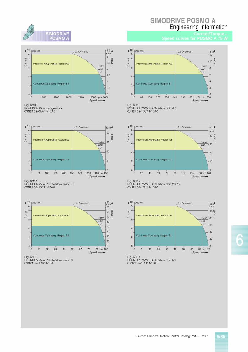
Siemens General Motion Control Catalog Part 3 · 2001 6/85
SIMODRIVE POSMO A
6
SIMODRIVEPOSMO A
Engineering InformationCurrent/Torque –
Speed curves for POSMO A 75 W
0 600 1200 1800 2400 3000 36000
2
4
6
8
10
Curr
ent
Speedrpm
A
To
rqu
e
lb-in
Intermittent Operating Region S3
Continous Operating Region S1
2x Overload
Ratedload
0
0,5
1
1,5
2
2,5
3
3,5GMC-5091
Fig. 6/109POSMO A 75 W w/o gearbox6SN21 32-0AA11-1BA0
Fig. 6/110POSMO A 75 W PG Gearbox ratio 4.56SN21 32-1BC11-1BA0
0 267 444 533 622 711 8000
2
4
6
8
10
Curr
ent
Speedrpm
A
To
rqu
e
lb-in
Intermittent Operating Region S3
Continous Operating Region S1
2x Overload
Ratedload
0
2
4
6
8
10
12
GMC-5092
35617889
Fig. 6/111POSMO A 75 W PG Gearbox ratio 8.06SN21 32-1BF11-1BA0
0 150 250 300 350 400 4500
2
4
6
8
10
Curr
ent
Speedrpm
A
To
rqu
e
lb-in
Intermittent Operating Region S3
Continous Operating Region S1
2x Overload
Ratedload
0
5
10
15
20
GMC-5093
20010050
Fig. 6/112POSMO A 75 W PG Gearbox ratio 20.256SN21 32-1CK11-1BA0
0 59 99 119 138 158 1780
2
4
6
8
10C
urr
ent
Speedrpm
A
To
rqu
e
lb-in
Intermittent Operating Region S3
Continous Operating Region S1
2x Overload
Ratedload
0
10
20
30
50GMC-5094
794020
40
Fig. 6/113POSMO A 75 W PG Gearbox ratio 366SN21 32-1CR11-1BA0
0 33 56 67 78 89 1000
2
4
6
8
10
Curr
ent
Speedrpm
A
To
rqu
e
lb-in
Intermittent Operating Region S3
Continous Operating Region S1
2x Overload
Ratedload
0
10
30
50
90GMC-5095
442211
70
20
40
60
80
Fig. 6/114POSMO A 75 W PG Gearbox ratio 506SN21 32-1CU11-1BA0
0 24 40 48 56 64 720
2
4
6
8
10
Curr
ent
Speedrpm
A
To
rqu
e
lb-in
Intermittent Operating Region S3
Continous Operating Region S1
2x Overload
Ratedload
0
40
120GMC-5096
32168
80
20
60
100
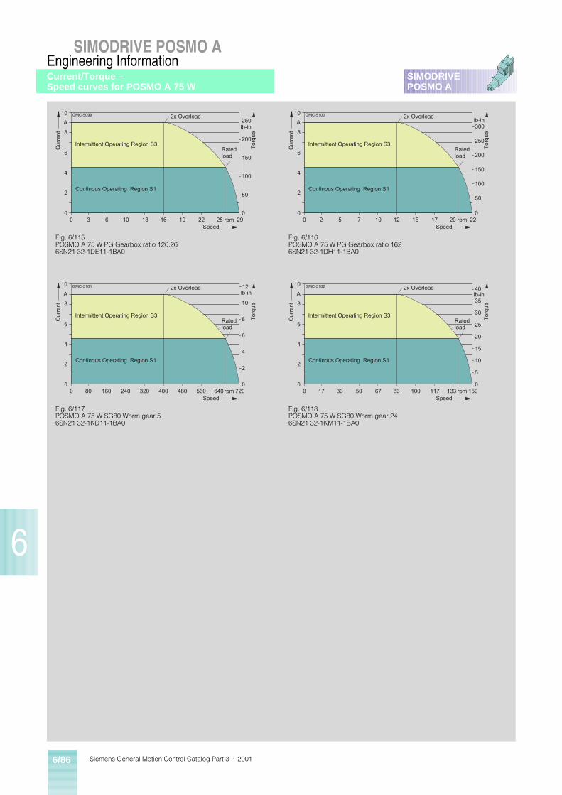
Siemens General Motion Control Catalog Part 3 · 20016/86
SIMODRIVE POSMO A
6
SIMODRIVEPOSMO A
Engineering InformationCurrent/Torque – Speed curves for POSMO A 75 W
0 10 16 19 22 25 290
2
4
6
8
10
Curr
ent
Speedrpm
A
To
rqu
e
lb-in
Intermittent Operating Region S3
Continous Operating Region S1
2x Overload
Ratedload
0
250GMC-5099
1363
200
50
100
150
Fig. 6/115POSMO A 75 W PG Gearbox ratio 126.266SN21 32-1DE11-1BA0
Fig. 6/116POSMO A 75 W PG Gearbox ratio 1626SN21 32-1DH11-1BA0
0 7 12 15 17 20 220
2
4
6
8
10
Curr
ent
Speedrpm
A
To
rqu
e
lb-in
Intermittent Operating Region S3
Continous Operating Region S1
2x Overload
Ratedload
0
150
GMC-5100
1052
250
50
100
200
300
Fig. 6/117POSMO A 75 W SG80 Worm gear 56SN21 32-1KD11-1BA0
0 240 400 480 560 640 7200
2
4
6
8
10
Curr
ent
Speedrpm
A
To
rqu
e
lb-in
Intermittent Operating Region S3
Continous Operating Region S1
2x Overload
Ratedload
0
6
GMC-5101
32016080
10
2
4
8
12
Fig. 6/118POSMO A 75 W SG80 Worm gear 246SN21 32-1KM11-1BA0
0 50 83 100 117 133 1500
2
4
6
8
10C
urr
ent
Speedrpm
A
To
rqu
e
lb-in
Intermittent Operating Region S3
Continous Operating Region S1
2x Overload
Ratedload
0
5
15
25
40GMC-5102
673317
10
20
30
35
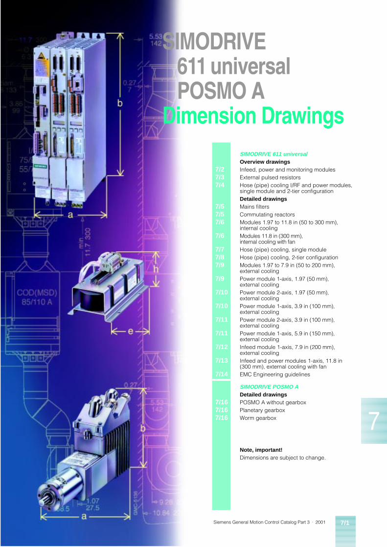
Siemens General Motion Control Catalog Part 3 · 2001 7/1
7
7/27/37/4
7/57/57/6
7/6
7/77/87/9
7/9
7/10
7/10
7/11
7/11
7/12
7/13
7/14
SIMODRIVE 611 universalOverview drawingsInfeed, power and monitoring modulesExternal pulsed resistorsHose (pipe) cooling I/RF and power modules, single module and 2-tier configurationDetailed drawingsMains filtersCommutating reactorsModules 1.97 to 11.8 in (50 to 300 mm), internal coolingModules 11.8 in (300 mm), internal cooling with fanHose (pipe) cooling, single moduleHose (pipe) cooling, 2-tier configurationModules 1.97 to 7.9 in (50 to 200 mm), external coolingPower module 1-axis, 1.97 (50 mm), external coolingPower module 2-axis, 1.97 (50 mm), external coolingPower module 1-axis, 3.9 in (100 mm), external coolingPower module 2-axis, 3.9 in (100 mm), external coolingPower module 1-axis, 5.9 in (150 mm), external coolingInfeed module 1-axis, 7.9 in (200 mm), external coolingInfeed and power modules 1-axis, 11.8 in (300 mm), external cooling with fanEMC Engineering guidelines
7/167/167/16
SIMODRIVE POSMO ADetailed drawingsPOSMO A without gearboxPlanetary gearboxWorm gearbox
Note, important!Dimensions are subject to change.
SIMODRIVE611 universalPOSMO A
Dimension Drawings
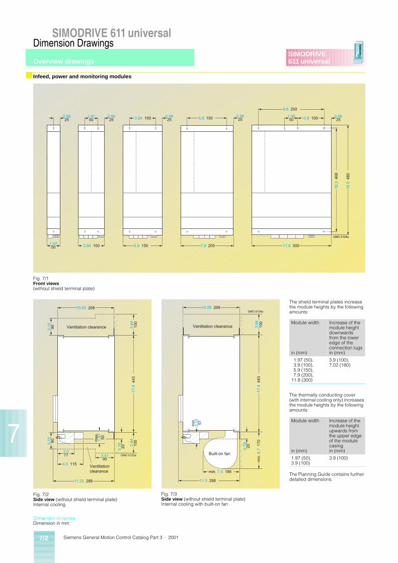
Siemens General Motion Control Catalog Part 3 · 20017/2
SIMODRIVE 611 universalDimension Drawings
SIMODRIVE611 universal
7
■ Infeed, power and monitoring modules
GMC-5104a
0.9825
0.9825
1.9750
0.9825
0.9825
1.9650
0.9825
1.9750
3.94 100 5.9 150
9.8 250
3.9 100
18.3
466
18.9
480
11.8 3007.9 2005.9 1503.94 100
Fig. 7/1Front views(without shield terminal plate)
Fig. 7/2Side view (without shield terminal plate)Internal cooling
The shield terminal plates increase the module heights by the following amounts:
The thermally conducting cover (with internal cooling only) increases the module heights by the following amounts:
The Planning Guide contains further detailed dimensions.
Module width
in (mm)
Increase of the module height downwards from the lower edge of the connection lugsin (mm)
1.97 (50), 3.9 (100), 5.9 (150), 7.9 (200),
11.8 (300)
3.9 (100), 7.02 (180)
Module width
in (mm)
Increase of the module height upwards from the upper edge of the module casingin (mm)
1.97 (50), 3.9 (100)
3.9 (100)
Fig. 7/3Side view (without shield terminal plate)Internal cooling with built-on fan
10.55 268
11.33 288
4.5 115
3.15 80
3.15 80
3.077
0.79 20
17.4
443
3.5190
max
.1.
97 50
GMC-5132a
Ventilation clearance
Ventilationclearance
3.94
100
3.94
10
0
GMC-5105a10.55 268
11.3 288
min. 7.4 188
min
.2.
24 57
0.79 20
min
. 6.7
170
17.4
443
3.94
10
0
Ventilation clearance
Built-on fan
Dimension in inchesDimension in mm
Overview drawings
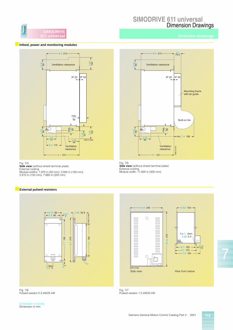
Siemens General Motion Control Catalog Part 3 · 2001 7/3
SIMODRIVE 611 universalDimension Drawings
SIMODRIVE611 universal
7
■ Infeed, power and monitoring modules
■ External pulsed resistors
GMC-5106a
IP 20 IP 54
3.15 80
3.15 80
0.79 20
3.5490
max
.1.
97 50
3.077
8.3 213
4.5 115
9.1 231
max.2.769
3.94
100
3.94
100
Ventilation clearance
Ventilationclearance
Fig. 7/4Side view (without shield terminal plate)External coolingModule widths: 1.970 in (50 mm), 3.940 in (100 mm), 5.910 in (150 mm), 7.880 in (200 mm)
Fig. 7/5Side view (without shield terminal plate)External cooling Module width: 11.820 in (300 mm)
GM
C-5
107b
IP 20 IP 54
8.4 213
9.1 231
min. 7.4 188
3.179.5
3.15 80
3.15 80 m
ax.
2.2
56
3.5490
Ventilation clearance
Ventilationclearance
Built-on fan
Mounting framewith air guide
GM
C-5
108b
3.14 802.6 66
2.08 52.8
7.7
196
8.3
210
6.3
160
0.277
0.27 7∅ diam.
0.2 5
Fig. 7/6Pulsed resistor 0.3 kW/25 kW
Fig. 7/7Pulsed resistor 1.5 kW/25 kW
4 x ∅ diam.0.26 6.5
GMC-5109a
9.4 240 5.62 143
6.1 1556.7 170
7.6 193
0.297.5
16.1
4 4
10
Side view View from below
Dimension in inchesDimension in mm
Overview drawings
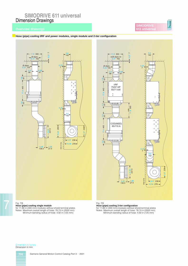
Siemens General Motion Control Catalog Part 3 · 20017/4
SIMODRIVE 611 universalDimension Drawings
SIMODRIVE611 universal
7
■ Hose (pipe) cooling I/RF and power modules, single module and 2-tier configuration
5.6142
GM
C-5
135a
Ø diam.6.37 162
2.6467
Ø diam.5.23 133
3.999
17.4
443
3.8
97
11.8 300
0.27
7
5.45138.5
1.0827.5
5.6142
0.277
0.277
9.37
238
9.37 238
10.94 278
10.2
3 2
60
3.8
97
9.35
237.
5
Fig. 7/8Hose (pipe) cooling single modulefor 11.88 in (300 mm) modules without shield terminal platesNotes: Maximum overall length of hose: 78.74 in (2000 mm)
Minimum bending radius of hose: 4.92 in (125 mm)
Fig. 7/9Hose (pipe) cooling 2-tier configurationfor 11.88 in (300 mm) modules without shield terminal platesNotes: Maximum overall length of hose: 78.74 in (2000 mm)
Minimum bending radius of hose: 4.92 in (125 mm)
GM
C-5
136
Ø diam.6.37 162
2.6467
Ø diam.5.23 133
3.999
3.8
9717
.4 4
43
11.8 300
min
.11
.8 3
009.
3523
7.5
5.45138.5
1.0827.5
5.6142
0.277
0.27
7
5.6142
0.277
9.37 238
10.94 278
I/RF75/97 HP55/71 kW
COD(MSD)85/110 A
3.8
973.
897
3.8
9717
.4 4
43
9.37
238
Dimension in inchesDimension in mm
Overview drawings
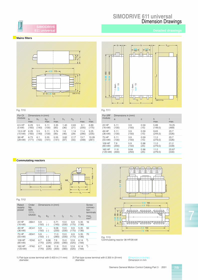
Siemens General Motion Control Catalog Part 3 · 2001 7/5
SIMODRIVE 611 universalDimension Drawings
SIMODRIVE611 universal
7
■ Mains filters
■ Commutating reactors
h 2h 1
h
I
I1
b 2 b 1 b
GMC-5110a
4.52 115
0.26 6.6
Fig. 7/10
For OI module
Dimensions in (mm)
bmax.
b1 b2max.
hmax.
h1 h2 Imax.
I1max.
6.5 HP(5 kW)
6.29(160)
5.5(140)
5.11(130)
3.35(85)
1.40(36)
0.83(21)
8.1(205)
6.89(175)
13.5 HP(10 kW)
6.29(160)
5.5(140)
5.11(130)
3.74(95)
1.8(46)
1.14(29)
11.4(290)
9.25(235)
38 HP(28 kW)
6.73(171)
6.1(155)
5.55(141)
5.55(141)
3.82(97)
2.17(55)
13.7(348)
10.28(261)
Fig. 7/11
For I/RF module
Dimensions in (mm)
a b c hmax.
Imax.
22 HP(16 kW)
5.11 (130)
3.9 (100)
0.59 (15)
5.89 (149,5)
19.25 (489)
49 HP(36 kW)
5.11 (130)
3.9 (100)
0.59 (15)
9.63 (244,5)
20.7 (526)
75 HP(55 kW)
5.11 (130)
3.9 (100)
0.59 (15)
11.0 (279,5)
20.7 (526)
109 HP(80 kW)
7.9 (200)
5.9 (150)
0.98 (25)
11.0 (279,5)
21.2 (539)
160 HP(120 kW)
11.8 (300)
9.84 (250)
0.98 (25)
11.0 (279,5)
20.87 (530)
b ccb hmax.
I ma
x.
a a1) GMC-5112a
18.8
9 4
80
18.3
4 4
66
3.9100
1.9750
∅ d
iam
.
0.51
13
∅ d
iam
.
0.51
13
n1
I2
n2
b2
b3
max
. h
M6
GM
C-5
111
Fig. 7/12
Rated supply power
Order No. 6SN 1111-0AA00-
Dimensions in (mm) Screw connec-tion terminals
b2 b3 h I2 n1 n2 max.mm2
22 HP(16 kW)
-0BA1 5.9(150)
–(–)
5.71(145)
13.0(330)
6.9(175)
5.35(136)
16
49 HP(36 kW)
-0CA1 5.9(150)
–(–)
9.06(230)
13.0(330)
6.9(175)
5.35(136)
50
75 HP(55 kW)
-0DA1 5.9(150)
–(–)
11.0(280)
13.0(330)
6.9(175)
5.35(136)
70
109 HP(80 kW)
-1EA0 6.7(170)
8.86(225)
7.9(200)
15.0(380)
12.8(325)
6.14(156)
2)
160 HP(120 kW)
-1FA0 6.7(170)
8.86(225)
11.8(300)
15.0(380)
12.8(325)
6.14(156)
2)
Fig. 7/13Commutating reactor 38 HP/28 kW
GM
C-5
113a
6.53 1664.4 113
5.9 150
7.0 178
6.8
173
3.46
88
2.68
68
2.52
64
1) Flat-type screw terminal with 0.433 in (11 mm) diameter.
2) Flat-type screw terminal with 0.355 in (9 mm) diameter.
Dimension in inchesDimension in mm
Detailed drawings
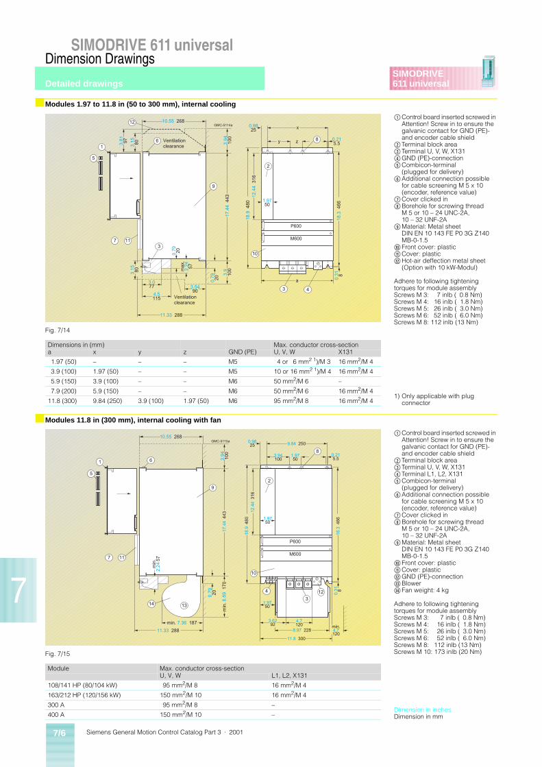
Siemens General Motion Control Catalog Part 3 · 20017/6
SIMODRIVE 611 universalDimension Drawings
SIMODRIVE611 universal
7
■ Modules 1.97 to 11.8 in (50 to 300 mm), internal cooling
■ Modules 11.8 in (300 mm), internal cooling with fan
M600
P600
GMC-5114a
11.33 288
4.5115
3.5490
3.077
3.9
100
0.79 20
max
.2.
24 57
3.15 80
3.15 803.81 97
10.55 268
17.4
4 4
43
a 0.31 8
1.9750
18.9
480
12.4
4 3
16
0.9825 x
0.215.5
18.3
466
3.94
100
y z
0.79 20
1173
12
1
5
6
9
2
8
10
43
Ventilationclearance
Ventilationclearance
Fig. 7/14
Dimensions in (mm) Max. conductor cross-sectiona x y z GND (PE) U, V, W X131
1.97 (50) – – – M5 4 or 6 mm2 1)/M 3 16 mm2/M 4
3.9 (100) 1.97 (50) – – M5 10 or 16 mm2 1)/M 4 16 mm2/M 4
5.9 (150) 3.9 (100) – – M6 50 mm2/M 6 –
7.9 (200) 5.9 (150) – – M6 50 mm2/M 6 16 mm2/M 4
11.8 (300) 9.84 (250) 3.9 (100) 1.97 (50) M6 95 mm2/M 8 16 mm2/M 4
$Control board inserted screwed in Attention! Screw in to ensure the galvanic contact for GND (PE)- and encoder cable shield
%Terminal block area&Terminal U, V, W, X131(GND (PE)-connection)Combicon-terminal
(plugged for delivery)*Additional connection possible
for cable screening M 5 x 10 (encoder, reference value)
+Cover clicked in,Borehole for screwing thread
M 5 or 10 – 24 UNC-2A, 10 – 32 UNF-2A
-Material: Metal sheet DIN EN 10 143 FE P0 3G Z140 MB-0-1.5
.Front cover: plastic/Cover: plastic0Hot-air deffection metal sheet
(Option with 10 kW-Modul)
Adhere to following tightening torques for module assemblyScrews M 3: 7 inlb ( 0.8 Nm)Screws M 4: 16 inlb ( 1.8 Nm)Screws M 5: 26 inlb ( 3.0 Nm)Screws M 6: 52 inlb ( 6.0 Nm)Screws M 8: 112 inlb (13 Nm)
1) Only applicable with plug connector
GMC-5115a
M600
P600
10.55 268
11.33 288
min. 7.36 187
8.97 228
3.6292
1.9750
4.7120
11.8 300
1.9750
0.79 20
17.4
4 4
433.
9410
0
0.9825
3.94100
1.9750
9.84 250
0.215.5
18.9
480
12.4
4 3
16
18.3
466
0.31 8
min
. 2.
24 5
7
min
. 6.6
9 1
70
min.4.7120
117
1
5
6
1314
9
2
8
10
3
124
Fig. 7/15
Module Max. conductor cross-sectionU, V, W L1, L2, X131
108/141 HP (80/104 kW) 95 mm2/M 8 16 mm2/M 4
163/212 HP (120/156 kW) 150 mm2/M 10 16 mm2/M 4
300 A 95 mm2/M 8 –
400 A 150 mm2/M 10 –
$Control board inserted screwed in Attention! Screw in to ensure the galvanic contact for GND (PE)- and encoder cable shield
%Terminal block area&Terminal U, V, W, X131(Terminal L1, L2, X131)Combicon-terminal
(plugged for delivery)*Additional connection possible
for cable screening M 5 x 10 (encoder, reference value)
+Cover clicked in,Borehole for screwing thread
M 5 or 10 – 24 UNC-2A, 10 – 32 UNF-2A
-Material: Metal sheet DIN EN 10 143 FE P0 3G Z140 MB-0-1.5
.Front cover: plastic/Cover: plastic0GND (PE)-connection1Blower2Fan weight: 4 kg
Adhere to following tightening torques for module assemblyScrews M 3: 7 inlb ( 0.8 Nm)Screws M 4: 16 inlb ( 1.8 Nm)Screws M 5: 26 inlb ( 3.0 Nm)Screws M 6: 52 inlb ( 6.0 Nm)Screws M 8: 112 inlb (13 Nm)Screws M 10: 173 inlb (20 Nm)
Dimension in inchesDimension in mm
Detailed drawings
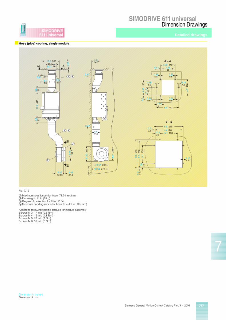
Siemens General Motion Control Catalog Part 3 · 2001 7/7
SIMODRIVE 611 universalDimension Drawings
SIMODRIVE611 universal
7
■ Hose (pipe) cooling, single module
2
3
1 4
1 4
1.3835
GM
C-5
116a
Ø diam.6.37 162
2.6467
Ø diam.5.23 133
3.999
3.8
9717
.4 4
43
0.27
7
5.45138.5
1.0827.5
5.6142
0.277
5.6142
0.277
9.37 238
10.94 278
10.2
3 2
60
A AB
B
A � A
B � B
0.225.5
3.4688
0.184.5
4.33 110
1.4637
6.4 162
4.7
120
2.16 554.33
110
0.2 5
0.4311
5.1 1307.9 2008.5 215
0.37.5
5.1
130
1.38 35
7.9
200
8.5
215
0.3
7.5
0.184.5
11.8 300
3.8
97
9.35
237.
5
9.37
238
0.225.5
0.184.5
0.225.5
0.225.5
Fig. 7/16
$Maximum total length for hose: 78.74 in (2 m)% Fan weight: 11 lb (5 kg)&Degree of protection for filter: IP 54(Minimum bending radius for hose: R = 4.9 in (125 mm)
Adhere to following tighting torques for module assemblyScrews M 3: 7 inlb (0.8 Nm)Screws M 4: 16 inlb (1.8 Nm)Screws M 5: 26 inlb (3 Nm)Screws M 6: 52 inlb (6 Nm)
Dimension in inchesDimension in mm
Detailed drawings
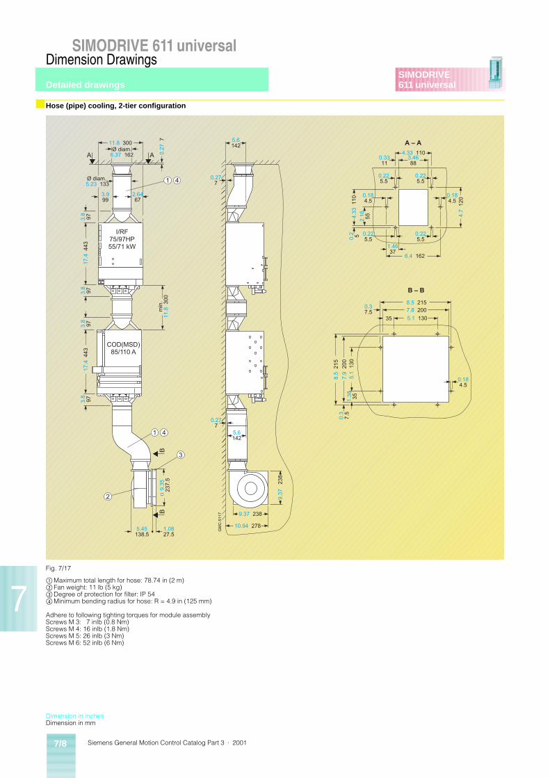
Siemens General Motion Control Catalog Part 3 · 20017/8
SIMODRIVE 611 universalDimension Drawings
SIMODRIVE611 universal
7
■ Hose (pipe) cooling, 2-tier configuration
3
2
1 4
1 4
Ø diam.6.37 162
35
B
A � A
B � B
0.225.5
3.4688
0.184.5
4.33 110
1.4637
6.4 162
4.7
120
2.16 554.
33 1
100.
2 5
0.3311
5.1 1307.8 2008.5 215
0.37.5
5.1
130
1.38 35
7.9
200
8.5
215
0.3
7.5
0.184.5
2.6467
Ø diam. 5.23 133
3.999
17.4
443
min
.11
.8 3
00
17.4
443
3.8
97
9.35
237.
5
5.45138.5
1.0827.5
5.6142
0.277
0.27
7
5.6142
0.277
9.37
23
8
9.37 238
10.94 278
I/RF75/97HP55/71 kW
COD(MSD)85/110 A
GM
C-5
117B
AA
11.8 300
3.8
973.
897
3.8
97
0.225.5
0.225.5
0.225.5
0.184.5
Fig. 7/17
$Maximum total length for hose: 78.74 in (2 m)% Fan weight: 11 lb (5 kg)&Degree of protection for filter: IP 54(Minimum bending radius for hose: R = 4.9 in (125 mm)
Adhere to following tighting torques for module assemblyScrews M 3: 7 inlb (0.8 Nm)Screws M 4: 16 inlb (1.8 Nm)Screws M 5: 26 inlb (3 Nm)Screws M 6: 52 inlb (6 Nm)
Dimension in inchesDimension in mm
Detailed drawings
Siemens General Motion Control Catalog Part 3 · 2001 7/9
SIMODRIVE 611 universalDimension Drawings
SIMODRIVE611 universal
7
■ Modules 1.97 to 7.9 in (50 to 200 mm), external cooling
■ Power module 1-axis, 1.97 in (50 mm), external cooling
20 8
GMC-5118b
IP20 IP54
3.94 1009.1 231
0.3910
3.14 80
3.14 80
8.3 211
max
.2.
36 60
15.3
389
17.4
4 4
43
18.3
446
12.4
4 3
16
0.31
∅ 0.266.5
x
a
18.9
480
1 6
12
9
3
117
5
8
2
103
40.79
Ventilationclearance
Ventilationclearance
Hea
l sin
k
Seal
Fig. 7/18
Dimensions in (mm) Max. conductor cross-sectiona x GND (PE) U, V, W X131
1.97 (50) – M 5 4 or 6 mm2 1)/M 3 16 mm2/M 4
3.9 (100) 1.97 (50) M 5 10 or 16 mm2 1)/M 4 16 mm2/M 4
5.9 (150) 3.9 (100) M 6 50 mm2/M 6 –
7.9 (200) 5.9 (150) M 6 50 mm2/M 6 16 mm2/M 4
$Control board inserted screwed in Attention! Screw in to ensure the galvanic contact for GND (PE)- and encoder cable shield
%Terminal block area&Terminal U, V, W, X131(GND (PE)-connection)Combicon-terminal
(plugged for delivery)(Not included in modules with pulse-interface)
*Additional connection possible for cable screening M 5 x 10 (encoder, reference value)
+Cover clicked in,Borehole for screwing thread
M 5 or 10 – 24 UNC-2A, 10 – 32 UNF-2A
-Material: Metal sheet DIN EN 10 143 FE P0 3G Z140 MB-0-1.5
.Front cover: plastic/Cover: plastic0Modules with pulse interface:
IP 00
Adhere to following tightening torques for module assemblyScrews M 3: 7 inlb (0.8 Nm)Screws M 4: 16 inlb (1.8 Nm)Screws M 5: 26 inlb (3.0 Nm)
1) Only applicable with plug connector
Fig. 7/19
Adhere to following tightening torques for module assemblyScrews M 3: 7 inlb (0.8 Nm)Screws M 4: 16 inlb (1.8 Nm)Screws M 5: 26 inlb (3.0 Nm)Screws M 6: 52 inlb (6.0 Nm)
GM
C-5
120a
0
15.03381.8
3.2783
1.3330
0.31 8
0
9.1
231
11.8
300
0.15
3.7
5
1.97
50
18.2 463
0
0.79 20
18.9 48018.66 474
Æ 0.26
6,5
00.
28 7
0.7318.5
11.7
6 2
98.8
18.3
466
2.05 52
1.436
M 5
1.76
44.
750.
97 2
4.8
1.63
41.
5
0.86 21.81.67 42.5
Hea
l sin
k
0.94 24
Assembly breakthrough
Dimension in inchesDimension in mm
Detailed drawings
Siemens General Motion Control Catalog Part 3 · 20017/10
SIMODRIVE 611 universalDimension Drawings
SIMODRIVE611 universal
7
■ Power module 2-axis, 1.97 in (50 mm), external cooling
■ Power module 1-axis, 3.9 in (100 mm), external cooling
GM
C-5
120a
0
15.03381.8
3.2783
1.3330
0.31 8
0
9.1
231
11.8
300
0.15
3.7
5
1.97
50
18.2 463
0
0.79 20
18.9 48018.66 474
Æ 0.26
6,5
00.
28 7
0.7318.5
11.7
6 2
98.8
18.3
466
2.05 52
1.436
M 5
1.76
44.
750.
97 2
4.8
1.63
41.
5
0.86 21.81.67 42.5
Hea
l sin
k
0.94 24
Fig. 7/20
Adhere to following tightening torques for module assemblyScrews M 3: 7 inlb (0.8 Nm)Screws M 4: 16 inlb (1.8 Nm)Screws M 5: 26 inlb (3.0 Nm)Screws M 6: 52 inlb (6.0 Nm)
Assembly breakthrough
GM
C-5
121a
M 5
16.58421.1
3.2382
1.2632
0
3.4186.5
15.4
2 3
91.7
18.3
466
0.7318.5
(0.71 18)1.9750
0.91 23
0.31 8
18.2 463
0
0
9.1
231
11.8
300
0.79 20
18.9 48018.66 474
3.9
100 0
0.28
70.
98 2
5
2.95
75
3.62
92
Æ 0.266.5
Hea
l sin
k
Fig. 7/21
Adhere to following tightening torques for module assemblyScrews M 3: 7 inlb (0.8 Nm)Screws M 4: 16 inlb (1.8 Nm)Screws M 5: 26 inlb (3.0 Nm)Screws M 6: 52 inlb (6.0 Nm)
Assembly breakthrough
Dimension in inchesDimension in mm
Detailed drawings
Siemens General Motion Control Catalog Part 3 · 2001 7/11
SIMODRIVE 611 universalDimension Drawings
SIMODRIVE611 universal
7
■ Power module 2-axis, 3.9 in (100 mm), external cooling
■ Power module 1-axis, 5.9 in (150 mm), external cooling
GM
C-5
122a
00.31 8
0.79 20
18.2 46318.66 47418.9 480
0
1.333
3.2783
0
11.8
300
9.1
23
1
0.15
3.7
5 0
0.98
25
2.12
53.
752.
95 7
53.
73 9
4.75
1.76
44.
75
3.9
100
00.28
7
1.63
41.
52.
24 5
7
3.6
91
.5
16.6421.7
18.3
466
1.6943
0.8221
1.9750
3.66 93
0.8722
13.3
4 3
38.8
0.94 24
2.04 52
1.9750
3.41 86.5
0.717.7
1.4436.5
1.4436.5 0.74
18. 8M 5Æ 0.26 6.5
1.6943
Hea
l sin
k
Fig. 7/22
Adhere to following tightening torques for module assemblyScrews M 3: 7 inlb (0.8 Nm)Screws M 4: 16 inlb (1.8 Nm)Screws M 5: 26 inlb (3.0 Nm)Screws M 6: 52 inlb (6.0 Nm)
Assembly breakthrough
GM
C-5
123a
00.31 8
0.79 20
18.2 46318.66 47418.9 480
0
1.333
3.2783
16.6421.7
18.3
466
15.3
9 3
90.8
0.94
23.9
0.5814.7
0.615.3 3.9 100
5.12 130
0
11.8
300
9.1
23
100.
41 1
0.5
0.98
25
4.92
125
5.9
15
05.
45
138.
5
M 5
Hea
l sin
k
Fig. 7/23
Adhere to following tightening torques for module assemblyScrews M 3: 7 inlb (0.8 Nm)Screws M 4: 16 inlb (1.8 Nm)Screws M 5: 26 inlb (3.0 Nm)Screws M 6: 52 inlb (6.0 Nm)
Assembly breakthrough
Dimension in inchesDimension in mm
Detailed drawings
Siemens General Motion Control Catalog Part 3 · 20017/12
SIMODRIVE 611 universalDimension Drawings
SIMODRIVE611 universal
7
■ Infeed module 1-axis, 7.9 in (200 mm), external cooling
Fig. 7/24
Adhere to following tightening torques for module assemblyScrews M 3: 7 inlb (0.8 Nm)Screws M 4: 16 inlb (1.8 Nm)Screws M 5: 26 inlb (3.0 Nm)Screws M 6: 52 inlb (6.0 Nm)
GM
C-5
140a
00.31 8
0.79 20
18.2 46318.66 474
18.9 480
0
1.333
3.2783
16.6421.7
0
11.8
300
9.1
231
0
2.38
60.
50.
98 2
5
6.9
175
7.9
200
7.4
188
.5
Hea
l sin
k
18.3
466
15.4
390
.80.
9423
.9
0.5814.7
1.3734.7
5.9 150
5.11 130 M 5
Assembly breakthrough
Dimension in inchesDimension in mm
Detailed drawings
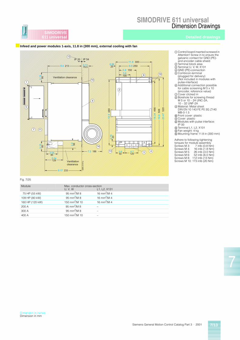
Siemens General Motion Control Catalog Part 3 · 2001 7/13
SIMODRIVE 611 universalDimension Drawings
SIMODRIVE611 universal
7
■ Infeed and power modules 1-axis, 11.8 in (300 mm), external cooling with fan
Fig. 7/25
Module Max. conductor cross-sectionU, V, W L1, L2, X131
75 HP (55 kW) 95 mm2/M 8 16 mm2/M 4
109 HP (80 kW) 95 mm2/M 8 16 mm2/M 4
160 HP (120 kW) 150 mm2/M 10 16 mm2/M 4
200 A 95 mm2/M 8 –
300 A 95 mm2/M 8 –
400 A 150 mm2/M 10 –
$Control board inserted screwed in Attention! Screw in to ensure the galvanic contact for GND (PE)- and encoder cable shield
%Terminal block area&Terminal U, V, W, X131(GND (PE)-connection)Combicon-terminal
(plugged for delivery)(Not included in modules with pulse-interface)
*Additional connection possible for cable screening M 5 x 10 (encoder, reference value)
+Cover clicked in,Borehole for screwing thread
M 5 or 10 – 24 UNC-2A, 10 – 32 UNF-2A
-Material: Metal sheet DIN EN 10 143 FE P0 3G Z140 MB-0-1.5
.Front cover: plastic/Cover: plastic0Modules with pulse interface:
IP 001Terminal L1, L2, X1312Fan weight: 4 kg3Mounting frame 11.8 in (300 mm)
Adhere to following tightening torques for module assemblyScrews M 3: 7 inlb (0.8 Nm)Screws M 4: 16 inlb (1.8 Nm)Screws M 5: 26 inlb (3.0 Nm)Screws M 6: 52 inlb (6.0 Nm)Screws M 8: 112 inlb (13 Nm)Screws M 10: 173 inlb (20 Nm)
GM
C-5
141a
IP 20 IP 54
8.4 213
9.17 233
7.3 186
3.1379.5
3.15 80
3.15 80
2.2
56
3.5490
1
5
5.04128
12
9
117
14
15
18.9
4
80
0.9925
18
.34
4
66
2
8
13 43
9.8 250
3.9100
5.9 150
11.8 300
10
0.79 20
19
.9 5
06
4.7120
3.692
20
.47
5
20
Ventilation clearance
Ventilationclearance
Dimension in inchesDimension in mm
Detailed drawings
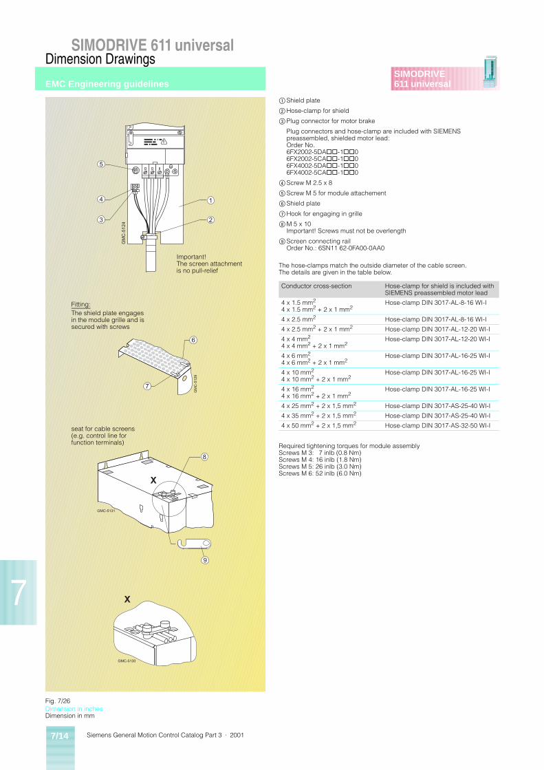
Siemens General Motion Control Catalog Part 3 · 20017/14
SIMODRIVE 611 universalDimension Drawings
SIMODRIVE611 universal
7
GM
C-5
124
1
2
5
4
3
GM
C-5
129
7
6
X
GMC-5130
X
GMC-5131
8
9
Fig. 7/26
$Shield plate
%Hose-clamp for shield
&Plug connector for motor brake
Plug connectors and hose-clamp are included with SIEMENS preassembled, shielded motor lead:Order No.6FX2002-5DA@@-1@@06FX2002-5CA@@-1@@06FX4002-5DA@@-1@@06FX4002-5CA@@-1@@0
(Screw M 2.5 x 8
)Screw M 5 for module attachement
*Shield plate
+Hook for engaging in grille
,M 5 x 10Important! Screws must not be overlength
-Screen connecting railOrder No.: 6SN11 62-0FA00-0AA0
The hose-clamps match the outside diameter of the cable screen.The details are given in the table below.
Required tightening torques for module assemblyScrews M 3: 7 inlb (0.8 Nm)Screws M 4: 16 inlb (1.8 Nm)Screws M 5: 26 inlb (3.0 Nm)Screws M 6: 52 inlb (6.0 Nm)
Conductor cross-section Hose-clamp for shield is included with SIEMENS preassembled motor lead
4 x 1.5 mm2
4 x 1.5 mm2 + 2 x 1 mm2Hose-clamp DIN 3017-AL-8-16 WI-I
4 x 2.5 mm2 Hose-clamp DIN 3017-AL-8-16 WI-I
4 x 2.5 mm2 + 2 x 1 mm2 Hose-clamp DIN 3017-AL-12-20 WI-I
4 x 4 mm2
4 x 4 mm2 + 2 x 1 mm2Hose-clamp DIN 3017-AL-12-20 WI-I
4 x 6 mm2
4 x 6 mm2 + 2 x 1 mm2Hose-clamp DIN 3017-AL-16-25 WI-I
4 x 10 mm2
4 x 10 mm2 + 2 x 1 mm2Hose-clamp DIN 3017-AL-16-25 WI-I
4 x 16 mm2
4 x 16 mm2 + 2 x 1 mm2Hose-clamp DIN 3017-AL-16-25 WI-I
4 x 25 mm2 + 2 x 1,5 mm2 Hose-clamp DIN 3017-AS-25-40 WI-I
4 x 35 mm2 + 2 x 1,5 mm2 Hose-clamp DIN 3017-AS-25-40 WI-I
4 x 50 mm2 + 2 x 1,5 mm2 Hose-clamp DIN 3017-AS-32-50 WI-I
Important! The screen attachment is no pull-relief
Fitting:The shield plate engages in the module grille and is secured with screws
seat for cable screens (e.g. control line for function terminals)
Dimension in inchesDimension in mm
EMC Engineering guidelines
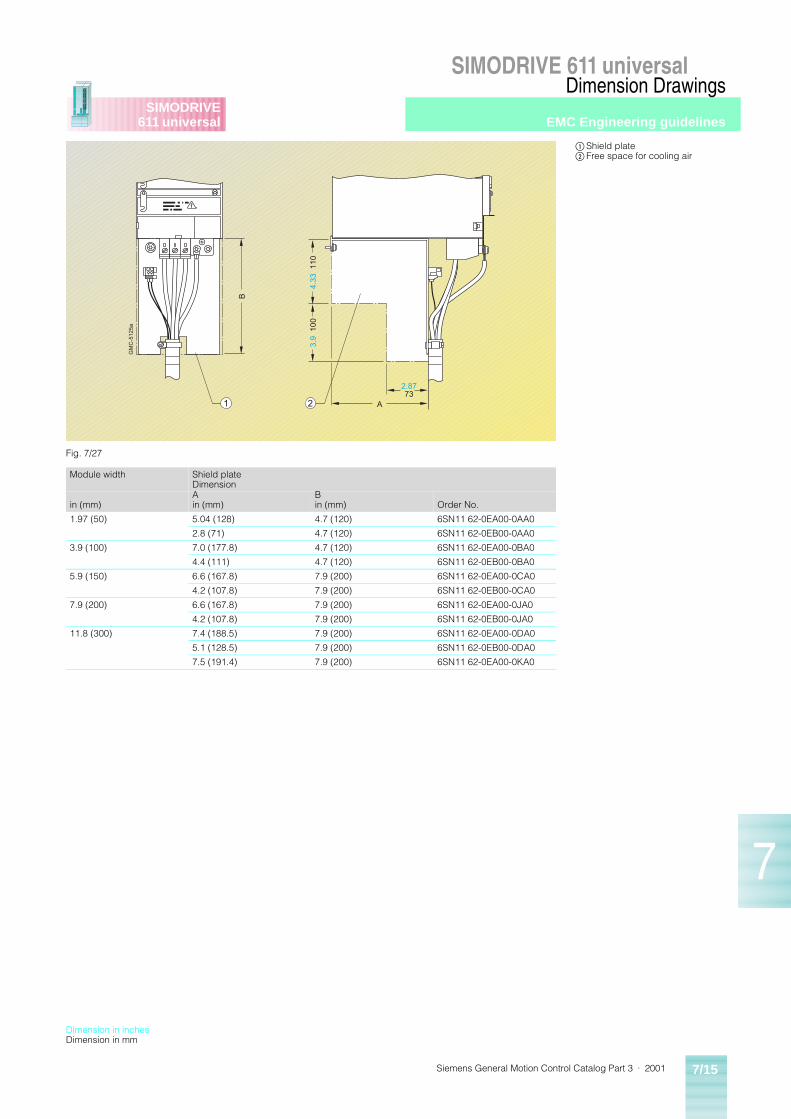
Siemens General Motion Control Catalog Part 3 · 2001 7/15
SIMODRIVE 611 universalDimension Drawings
SIMODRIVE611 universal
7
1 2
B
GM
C-5
125a
3.9
100
2.8773
A
4.33
110
Fig. 7/27
Module width Shield plateDimension
in (mm)Ain (mm)
Bin (mm) Order No.
1.97 (50) 5.04 (128) 4.7 (120) 6SN11 62-0EA00-0AA0
2.8 (71) 4.7 (120) 6SN11 62-0EB00-0AA0
3.9 (100) 7.0 (177.8) 4.7 (120) 6SN11 62-0EA00-0BA0
4.4 (111) 4.7 (120) 6SN11 62-0EB00-0BA0
5.9 (150) 6.6 (167.8) 7.9 (200) 6SN11 62-0EA00-0CA0
4.2 (107.8) 7.9 (200) 6SN11 62-0EB00-0CA0
7.9 (200) 6.6 (167.8) 7.9 (200) 6SN11 62-0EA00-0JA0
4.2 (107.8) 7.9 (200) 6SN11 62-0EB00-0JA0
11.8 (300) 7.4 (188.5) 7.9 (200) 6SN11 62-0EA00-0DA0
5.1 (128.5) 7.9 (200) 6SN11 62-0EB00-0DA0
7.5 (191.4) 7.9 (200) 6SN11 62-0EA00-0KA0
$Shield plate%Free space for cooling air
Dimension in inchesDimension in mm
EMC Engineering guidelines
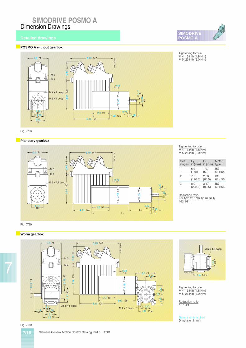
Siemens General Motion Control Catalog Part 3 · 20017/16
Dimension Drawings
7
SIMODRIVE POSMO A
SIMODRIVEPOSMO A
■ POSMO A without gearbox
■ Planetary gearbox
■ Worm gearbox
GM
C-5
126a
M 5
M 4
M 4 x 7 deep
M 5 x 7 deep
1.4236
2.8 71
∅ 1.5740
1.9349
2.3 590.08
24.92 125 0.98
254.88 124
5.79 147
3.94
100
2.48
63
0.4311
2.48
63
∅ 0
.98
25
∅ 0
.31
8
Fig. 7/28
Tightening torqueM 4: 16 inlb (1.8 Nm)M 5: 26 inlb (3.0 Nm)
GM
C-5
127a
1
2
M 5
M 4
M 5 x 7,5 deep
L
2.8 71
1.5740
5.79 147
0.4311
2.48
63
3.94
100
2.3 594.88 124 L 0.98
25
0.123
2.48
63
∅2.
05 5
2
∅1.
2632
∅0.
4712
Fig. 7/29
Tightening torqueM 4: 16 inlb (1.8 Nm)M 5: 26 inlb (3.0 Nm)
Reduction ratio4.5:1/20.25:1/36:1/126.56:1/162:1/8:1
Gear stages
L1in (mm)
L2in (mm)
Motor type
1 6.9 (175)
1.97 (50)
BG 63 x 55
2 7.5 (190.5)
2.58 (65.5)
BG 63 x 55
3 8.0 (202.5)
3.17 (80.5)
BG 63 x 55
GM
C-5
128a
2.8 71
2.2 56
M 5
M 4
M 5 x 4,8 deepM 4 x 8 deep
∅ 0
.39
10
∅ 1.4236
1.61 41
1.1830
1.1830
1.128
1.97
50
∅ 0
.98
25
3.94
100
2.48
63
2.3 594.92 125
4.88 124
5.79 147
0.4311 2.8 71
1.3835
2.48
63
1.97 50
1.5
381.
38 351.
22 31
Fig. 7/30
Tightening torqueM 4: 16 inlb (1.8 Nm)M 5: 26 inlb (3.0 Nm)
Reduction ratio5:1/24:1
GMC-5133
M 5 x 4,8 deep
1.18 30
1.97 50
Dimension in inchesDimension in mm
Detailed drawings

Siemens General Motion Control Catalog Part 3 · 2001 A/1
A
SIMODRIVE611 universalPOSMO A
AppendixA/2 Environment, Resources and Recycling,
Certificate ISO 9001
A/3 Confirmation, typical system configuration
A/4 Subject index
A/5 Order number index
A/6 Conversion tables
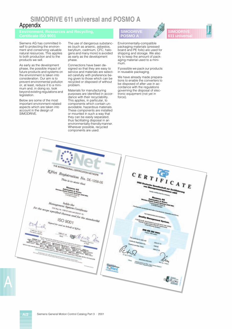
Siemens General Motion Control Catalog Part 3 · 2001A/2
SIMODRIVE 611 universal and POSMO AAppendix
A
SIMODRIVE611 universal
SIMODRIVEPOSMO A
Siemens AG has committed it-self to protecting the environ-ment and conserving valuable natural resources. This applies to both production and to the products we sell.
As early as the development phase, the possible impact of future products and systems on the environment is taken into consideration. Our aim is to prevent environmental pollution or, at least, reduce it to a mini-mum and, in doing so, look beyond existing regulations and legislation.
Below are some of the most important environment-related aspects which are taken into account in the design of SIMODRIVE.
The use of dangerous substanc-es (such as arsenic, asbestos, beryllium, cadmium, CFC, halo-gens and many more) is avoided as early as the development phase.
Connections have been de-signed so that they are easy to service and materials are select-ed carefully with preference be-ing given to those which can be recycled or disposed of without problem.
Materials for manufacturing purposes are identified in accor-dance with their recyclability. This applies, in particular, to components which contain un-avoidable, hazardous materials. These components are installed or mounted in such a way that they can be easily separated, thus facilitating disposal in an environmentally-friendly manner. Wherever possible, recycled components are used.
Environmentally-compatible packaging materials (pressed board and PE foils) are used for shipping and storage. We also try to keep the amount of pack-aging material used to a mini-mum.
If possible we pack our products in reusable packaging.
We have already made prepara-tions to enable the converters to be disposed of after use in ac-cordance with the regulations governing the disposal of elec-tronic equipment (not yet in force).
Environment, Resources and Recycling, Certificate ISO 9001
Siemens General Motion Control Catalog Part 3 · 2001 A/3
SIMODRIVE 611 universal and POSMO AAppendix
A
SIMODRIVE611 universal
SIMODRIVEPOSMO A
Confirmation,typical system configuration
Siemens General Motion Control Catalog Part 3 · 2001A/4
SIMODRIVE 611 universal and POSMO AAppendix
A
SIMODRIVE611 universal
SIMODRIVEPOSMO A
Page1- or 2-axis power module 6/632-tier configuration 3/6, 6/36
AAdapter terminal 3/6, 6/36Application selection 1/11Assessment factors 6/9Axis setup 6/83
BBacklash compensation 6/84Blanking plate 3/7, 6/34Braking resistors 2/5, 6/34Braking units 2/5, 6/34Built on fan 3/9Bus connector 2/11
CCables 2/10, 2/12,
3/14, 6/63Calculating example 6/12Calculating the DC link power for
the infeed module 6/6Centralized option board 6/69Checking the 24 V DC power supply
rating 6/7Cloosed-loop control plug-in units 3/4, 6/32Coding elements 3/6Commutating reactor 2/6, 3/10,
6/27Configuration sheet 6/11Connecting and wiring overview 6/76Connectors 3/14Control terminal strip 6/70Control terminals 6/46Cooling systems 6/37Current reduction curves 6/40Current/Torque-Speed curves 6/84Customer service 1/3
DDemo unit 3/11, 3/15Demonstration unit 3/15Dimension drawings 7/1Dimensioning of the infeed module 6/39Dimensioning of the power module 6/40Dimensioning of the power section
and drive 6/2Documentation 5/1Drive ES 3/6, 6/71
EElectromagnatic compatibility (EMC) 6/67Electronic documantation 5/2Encoder cables 6/63Encoders for position detection 6/68Engineering instructions 6/2External cooling 3/2, 3/3,
6/37
FFan 3/9Fault displays and messages 6/84FB 10 “CONTROL POSMO A” 6/80FB 11 “PARAMETERIZE POSMO A” 6/80
PageFB 12 “PARAMETERIZE ALL
POSMO A” 6/80Features 1/8Female coding elements 3/6Flow diagram 1/16
GGenaral documantation 5/2Guidelines 1/14
HHF commutating reactor 2/6, 3/10,
6/27Hose (pipe) cooling 3/2, 3/3,
3/8, 6/38Hose cooling package 3/8, 6/38
IInfeed modules 2/3, 3/2,
6/47Infeed modules (O/I and I/R) 6/51Infeed/regenerative feedback I/RF
modules 6/30Inputs/Outputs 6/84Integration in SIMATIC 6/69Internal cooling 3/2, 3/3,
6/37Introduction 1/2
JJerk limiting 6/84
LLAN cables 2/12, 3/14Line supply types 6/65
MMains filter package 3/10, 6/29Mains filters 2/6, 3/10,
6/28Male coding elements 3/6Manufacture documantation 5/2Monitoring module 2/6, 3/5,
6/33, 6/60Motor selection 4/1Mounting frame 3/7
OO/I and I/RF modules 6/30Operating modes 6/82Over voltage limiter module 2/6, 3/5,
6/29, 6/53Overload capability 6/29
PPlug-in unit 6/53Plug-in unit with optical sin/cos
encoder 3/4, 6/63Plug-in unit with resolver 3/4, 6/63Positioning motor 3/12POSMO 2/7, 3/13,
6/73Power and control terminals 6/46Power and encoder cables 6/63
PagePower cables 2/10, 3/14,
6/63Power Management Module 2/9, 3/15,
6/75Power modules 2/4, 3/3,
6/31, 6/49Power supply sizing 6/74Product selection 1/11PROFIBUS 3/4, 3/14,
6/69, 6/78Pulsed resistor 3/5, 6/34Pulsed resistor module 3/5, 6/62
RReferencing 6/83Regenerative feedback protection 6/74
SSevice documantation 5/2Shield contacting clip 3/6Shield terminal plate 3/9SIMATIC 6/69, 6/71,
6/80SIMATIC S7 function blocks 6/80SimoCom U 3/6, 6/70SIMODRIVE POSMO A 2/7, 3/13,
6/73SimoSize 6/72SITOP 2/9, 3/16,
6/74Stand-alone operation 6/84Start-up box 3/11Start-up tool “POSMO A Master” 6/81Start-up, parameterization and
diagnostics with SimoCom U 6/70System components/2-tier con-
figuration 6/36System components/Braking units
and braking resistors 2/5, 6/34System components/Infeed and
power modules 6/30System components/Monitoring
module 6/33System components/Plug-in units 6/32System overview 6/46System-/Line side components 6/27
TTechnical data 2/1Technology 6/68Terminal plate 3/9Terminale module 6/69Thermally conductive cover 3/9, 6/34Training courses 3/11Traversing blocks and programs 6/82
UUnit bus cable 3/6Unit design/Power and control
terminals 6/46Unregulated control/infeed O/I module 6/31
WWiring configuration overview 6/42
Subject index
Siemens General Motion Control Catalog Part 3 · 2001 A/5
SIMODRIVE 611 universal and POSMO AAppendix
A
SIMODRIVE611 universal
SIMODRIVEPOSMO A
Page1FK1FK60 4/21FK61 4/2
1FT1FT60 4/21FT61 4/2
6EP136EP13 31-2BA00 3/166EP13 33-2BA00 3/166EP13 34-2BA00 3/166EP13 36-2BA00 3/16
6EP146EP14 34-2BA00 3/166EP14 36-2BA00 3/166EP14 37-2BA00 3/166EP14 37-2BA10 3/16
6ES796ES79 72-0BA50-0XA0 3/146ES79 72-0BB50-0XA0 3/14
6FC6FC9 348-7BA 3/66FC9 348-7BB 3/6
6FX6FX2 6/63 6/646FX5 3/14, 6/63,
6/646FX50 08-5FA00-1FA0 3/14
6GK6GK15 00-0FC00 3/146GK19 05-6AA00 3/146GK19 05-6AB00 3/14
6SE71 946SE71 94-1LY00-0AA0 3/146SE71 94-1LY10-0AA0 3/14
6SN11 116SN11 11-0AA00-0BA1 3/10, 6/276SN11 11-0AA00-0CA1 3/10, 6/276SN11 11-0AA00-0DA1 3/10, 6/276SN11 11-0AA00-0EA1 3/10, 6/276SN11 11-0AA00-1FA0 3/10, 6/276SN11 11-0AA01-1AA0 3/10, 6/286SN11 11-0AA01-1BA0 3/10, 6/286SN11 11-0AA01-1CA0 3/10, 6/286SN11 11-0AA01-2BA0 3/10, 6/286SN11 11-0AA01-2BB0 3/10, 6/296SN11 11-0AA01-2CA0 3/10, 6/286SN11 11-0AA01-2CB0 3/10, 6/296SN11 11-0AA01-2DA0 3/10, 6/286SN11 11-0AA01-2DB0 3/10, 6/296SN11 11-0AA01-2EA0 3/10, 6/286SN11 11-0AA01-2EB0 3/10, 6/296SN11 11-0AA01-2FA0 3/10, 6/286SN11 11-0AA01-2FB0 3/10, 6/296SN11 11-0AB00-0AA0 3/5, 6/296SN11 11-1AA00-0CA0 3/10, 6/27
6SN11 126SN11 12-1AC01-0AA1 3/5, 6/33
6SN11 136SN11 13-1AA00-0CA0 3/5, 6/346SN11 13-1AA00-0DA0 3/5, 6/346SN11 13-1AB01-0BA1 3/5, 6/34
6SN11 146SN11 14-0NA00-0AA0 3/4, 6/696SN11 14-0NB00-0AA1 3/46SN11 14-0NB01-0AA0 3/4, 6/69
6SN11 186SN11 18-0NH00-0AA1 3/46SN11 18-0NH00-0AA1 6/536SN11 18-0NJ00-0AA1 3/46SN11 18-0NJ00-0AA1 6/546SN11 18-0NK00-0AA1 3/4
Page6SN11 18-0NK00-0AA1 6/536SN11 18-1NH00-0AA1 3/46SN11 18-1NH00-0AA1 6/536SN11 18-1NJ00-0AA1 3/46SN11 18-1NJ00-0AA1 6/546SN11 18-1NK00-0AA1 3/46SN11 18-1NK00-0AA1 6/53
6SN11 236SN11 23-1AA00-0AA1 3/3, 6/496SN11 23-1AA00-0BA1 3/3, 6/496SN11 23-1AA00-0CA1 3/3, 6/496SN11 23-1AA00-0DA1 3/3, 6/496SN11 23-1AA00-0EA1 3/3, 6/496SN11 23-1AA00-0HA1 3/3, 6/496SN11 23-1AA00-0JA1 3/3, 6/496SN11 23-1AA00-0JA1 3/3, 6/496SN11 23-1AA00-0KA1 3/3, 6/496SN11 23-1AA00-0KA1 3/3, 6/496SN11 23-1AA00-0LA1 3/3, 6/496SN11 23-1AA01-0FA1 3/3, 6/496SN11 23-1AA02-0FA1 3/3, 6/496SN11 23-1AB00-0AA1 3/3, 6/496SN11 23-1AB00-0BA1 3/3, 6/496SN11 23-1AB00-0CA1 3/3, 6/496SN11 23-1AB00-0HA1 3/3, 6/49
6SN11 246SN11 24-1AA00-0AA1 3/3, 6/496SN11 24-1AA00-0BA1 3/3, 6/496SN11 24-1AA00-0CA1 3/3, 6/496SN11 24-1AA00-0DA1 3/3, 6/496SN11 24-1AA00-0EA1 3/3, 6/496SN11 24-1AA00-0HA1 3/3, 6/496SN11 24-1AA00-0JA1 3/3, 6/496SN11 24-1AA00-0KA1 3/3, 6/496SN11 24-1AA00-0LA1 3/3, 6/496SN11 24-1AA01-0FA1 3/3, 6/496SN11 24-1AB00-0AA1 3/3, 6/496SN11 24-1AB00-0BA1 3/3, 6/496SN11 24-1AB00-0CA1 3/3, 6/496SN11 24-1AB00-0HA1 3/3, 6/49
6SN11 456SN11 45-1AA00-0CA0 3/2, 6/476SN11 45-1AA01-0AA1 3/2, 6/476SN11 45-1AA01-0AA1 3/2, 6/476SN11 45-1BA01-0BA1 3/2, 6/476SN11 45-1BA01-0DA1 3/2, 6/476SN11 45-1BA02-0CA1 3/2, 6/476SN11 45-1BB00-0DA1 3/2, 6/476SN11 45-1BB00-0EA1 3/2, 6/476SN11 45-1BB00-0EA1 3/2, 6/476SN11 45-1BB00-0FA1 3/2, 6/476SN11 45-1BB00-0FA1 3/2, 6/47
6SN11 466SN11 46-1AB00-0AB1 3/2, 6/476SN11 46-1AB00-0AB1 3/2, 6/476SN11 46-1AB00-0CA0 3/2, 6/476SN11 46-1BB00-0DA1 3/2, 6/476SN11 46-1BB00-0EA1 3/2, 6/476SN11 46-1BB00-0FA1 3/2, 6/476SN11 46-1BB01-0BA1 3/2, 6/476SN11 46-1BB02-0CA1 3/2, 6/47
6SN11 616SN11 61-0BA03-0CA1 3/3, 6/496SN11 61-1AA00-0AA1 3/6, 6/366SN11 61-1AA01-0AA0 3/6, 6/366SN11 61-1AA01-0BA0 3/6, 6/36
6SN11 626SN11 62-0BA01-0AA0 3/9, 6/346SN11 62-0BA02-0AA1 3/3, 6/496SN11 62-0BA02-0AA1 3/86SN11 62-0BA03-0AA1 3/3, 6/496SN11 62-0BA03-0AA1 3/8, 6/686SN11 62-0BA03-0CA1 3/8, 6/686SN11 62-0BA04-0AA1 3/76SN11 62-0BA04-0BA1 3/76SN11 62-0BA04-0CA1 3/76SN11 62-0BA04-0DA1 3/76SN11 62-0BA04-0DA1 3/7
Page6SN11 62-0BA04-0EA0 3/76SN11 62-0BA04-0FA1 3/76SN11 62-0BA04-0GA1 3/76SN11 62-0BA04-0HA1 3/76SN11 62-0BA04-0JA0 3/76SN11 62-0BA04-0JA0 3/7, 6/33,
6/346SN11 62-0EA00-0AA0 3/96SN11 62-0EA00-0BA0 3/96SN11 62-0EA00-0CA0 3/96SN11 62-0EA00-0DA0 3/96SN11 62-0EA00-0JA0 3/96SN11 62-0EA00-0KA0 3/96SN11 62-0EB00-0AA0 3/96SN11 62-0EB00-0AA0 3/96SN11 62-0EB00-0BA0 3/96SN11 62-0EB00-0CA0 3/96SN11 62-0EB00-0JA0 3/96SN11 62-0FA01-0AA0 3/66SN11 62-0GA00-0BA0 3/10, 6/296SN11 62-0GA00-0BA4 3/106SN11 62-0GA00-0CA0 3/10, 6/296SN11 62-0GA00-0DA0 3/10, 6/296SN11 62-0GA00-0EA0 3/10, 6/29
6SN11 826SN11 82-0TA00-2DP0 3/11
6SN11 976SN11 97-0AA00-0BP4 5/26SN11 97-0AB20-0BP2 5/26SN11 97-0AB40-0BP2 5/2
6SN21 326SN21 32-0AA11-1BA0 3/136SN21 32-1BC11-1BA0 3/136SN21 32-1BF11-1BA0 3/136SN21 32-1CK11-1BA0 3/136SN21 32-1CR11-1BA0 3/136SN21 32-1CU11-1BA0 3/136SN21 32-1DE11-1BA0 3/136SN21 32-1DH11-1BA0 3/136SN21 32-5KD11-1BA0 3/136SN21 32-5KM11-1BA0 3/13
6SN21 976SN21 97-0AA00-0BP1 5/2
6SN28 326SN28 32- 0CF00-0AA0 3/15
6SN28 926SN28 92-0PG00-0AA0 3/15
6SW17 006SW17 00-0JA00-0AA0 3/6, 6/716SW1700-0JA00-0AB2 6/716SW1700-0JC00-0AA0 6/71
6XV6XV1 3/14, 6/63,
6/646XV18 30-0EH10 3/146XV18 30-0EN20 3/146XV18 30-0EN50 3/146XV18 30-0ET10 3/146XV18 30-0ET20 3/146XV18 30-0ET50 3/146XV18 30-0JH10 3/146XV18 30-3EH10 3/14
9AK9AK10 14-1AA00 3/11
9LA9LA21 37-1AA00-1AA0 3/15
DRMSDRMS-02055 3/6, 5/2
DRSPDRSP-02062 5/2DRSP-02080 5/2
Order number index
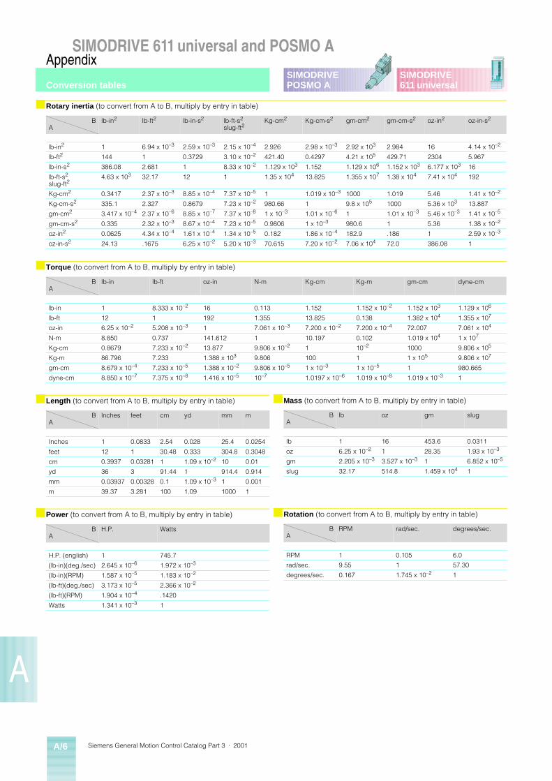
Siemens General Motion Control Catalog Part 3 · 2001A/6
SIMODRIVE 611 universal and POSMO AAppendix
A
SIMODRIVE611 universal
SIMODRIVEPOSMO A
■ Rotary inertia (to convert from A to B, multiply by entry in table)
BA
lb-in2 lb-ft2 lb-in-s2 lb-ft-s2
slug-ft2Kg-cm2 Kg-cm-s2 gm-cm2 gm-cm-s2 oz-in2 oz-in-s2
lb-in2 1 6.94 x 10⁻³ 2.59 x 10⁻³ 2.15 x 10⁻⁴ 2.926 2.98 x 10⁻³ 2.92 x 10³ 2.984 16 4.14 x 10⁻²
lb-ft2 144 1 0.3729 3.10 x 10⁻² 421.40 0.4297 4.21 x 10⁵ 429.71 2304 5.967
lb-in-s2 386.08 2.681 1 8.33 x 10⁻² 1.129 x 10³ 1.152 1.129 x 10⁶ 1.152 x 10³ 6.177 x 10³ 16
lb-ft-s2
slug-ft24.63 x 103 32.17 12 1 1.35 x 10⁴ 13.825 1.355 x 10⁷ 1.38 x 10⁴ 7.41 x 10⁴ 192
Kg-cm2 0.3417 2.37 x 10⁻³ 8.85 x 10⁻⁴ 7.37 x 10⁻⁵ 1 1.019 x 10⁻³ 1000 1.019 5.46 1.41 x 10⁻²
Kg-cm-s2 335.1 2.327 0.8679 7.23 x 10⁻² 980.66 1 9.8 x 10⁵ 1000 5.36 x 10³ 13.887
gm-cm2 3.417 x 10⁻⁴ 2.37 x 10⁻⁶ 8.85 x 10⁻⁷ 7.37 x 10⁻⁸ 1 x 10⁻³ 1.01 x 10⁻⁶ 1 1.01 x 10⁻³ 5.46 x 10⁻³ 1.41 x 10⁻⁵
gm-cm-s2 0.335 2.32 x 10⁻³ 8.67 x 10⁻⁴ 7.23 x 10⁻⁵ 0.9806 1 x 10⁻³ 980.6 1 5.36 1.38 x 10⁻²
oz-in2 0.0625 4.34 x 10⁻⁴ 1.61 x 10⁻⁴ 1.34 x 10⁻⁵ 0.182 1.86 x 10⁻⁴ 182.9 .186 1 2.59 x 10⁻³
oz-in-s2 24.13 .1675 6.25 x 10⁻² 5.20 x 10⁻³ 70.615 7.20 x 10⁻² 7.06 x 10⁴ 72.0 386.08 1
■ Torque (to convert from A to B, multiply by entry in table)
BA
lb-in lb-ft oz-in N-m Kg-cm Kg-m gm-cm dyne-cm
lb-in 1 8.333 x 10⁻² 16 0.113 1.152 1.152 x 10⁻² 1.152 x 10³ 1.129 x 10⁶
lb-ft 12 1 192 1.355 13.825 0.138 1.382 x 10⁴ 1.355 x 10⁷
oz-in 6.25 x 10⁻² 5.208 x 10⁻³ 1 7.061 x 10⁻³ 7.200 x 10⁻² 7.200 x 10⁻⁴ 72.007 7.061 x 10⁴
N-m 8.850 0.737 141.612 1 10.197 0.102 1.019 x 10⁴ 1 x 10⁷
Kg-cm 0.8679 7.233 x 10⁻² 13.877 9.806 x 10⁻² 1 10–2 1000 9.806 x 10⁵
Kg-m 86.796 7.233 1.388 x 10³ 9.806 100 1 1 x 10⁵ 9.806 x 10⁷
gm-cm 8.679 x 10⁻⁴ 7.233 x 10⁻⁵ 1.388 x 10⁻² 9.806 x 10⁻⁵ 1 x 10⁻³ 1 x 10⁻⁵ 1 980.665
dyne-cm 8.850 x 10⁻⁷ 7.375 x 10⁻⁸ 1.416 x 10⁻⁵ 10–7 1.0197 x 10⁻⁶ 1.019 x 10⁻⁸ 1.019 x 10⁻³ 1
■ Length (to convert from A to B, multiply by entry in table)
BA
lnches feet cm yd mm m
Inches 1 0.0833 2.54 0.028 25.4 0.0254
feet 12 1 30.48 0.333 304.8 0.3048
cm 0.3937 0.03281 1 1.09 x 10⁻² 10 0.01
yd 36 3 91.44 1 914.4 0.914
mm 0.03937 0.00328 0.1 1.09 x 10⁻³ 1 0.001
m 39.37 3.281 100 1.09 1000 1
■ Power (to convert from A to B, multiply by entry in table)
BA
H.P. Watts
H.P. (english) 1 745.7
(lb-in)(deg./sec) 2.645 x 10⁻⁶ 1.972 x 10⁻³
(lb-in)(RPM) 1.587 x 10⁻⁵ 1.183 x 10⁻²
(lb-ft)(deg./sec) 3.173 x 10⁻⁵ 2.366 x 10⁻²
(lb-ft)(RPM) 1.904 x 10⁻⁴ .1420
Watts 1.341 x 10⁻³ 1
■ Mass (to convert from A to B, multiply by entry in table)
BA
lb oz gm slug
lb 1 16 453.6 0.0311
oz 6.25 x 10⁻² 1 28.35 1.93 x 10⁻³
gm 2.205 x 10⁻³ 3.527 x 10⁻³ 1 6.852 x 10⁻⁵
slug 32.17 514.8 1.459 x 10⁴ 1
■ Rotation (to convert from A to B, multiply by entry in table)
BA
RPM rad/sec. degrees/sec.
RPM 1 0.105 6.0
rad/sec. 9.55 1 57.30
degrees/sec. 0.167 1.745 x 10⁻² 1
Conversion tables
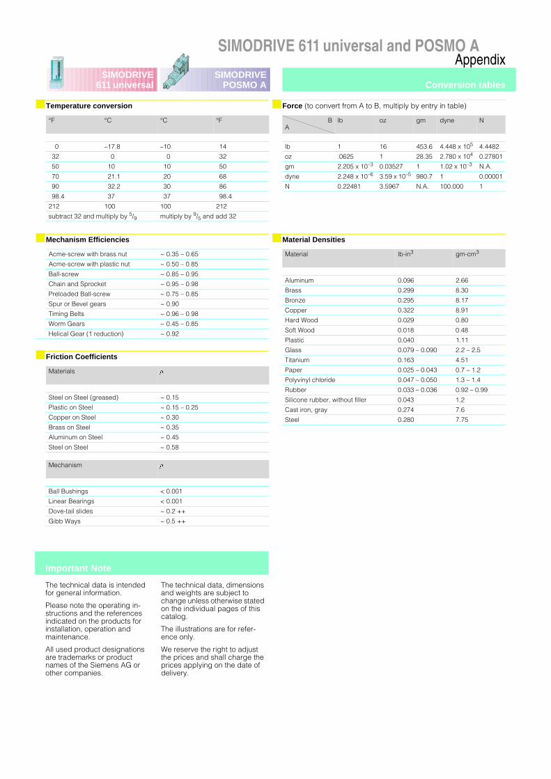
SIMODRIVE 611 universal and POSMO AAppendix
SIMODRIVE611 universal
SIMODRIVEPOSMO A
■ Temperature conversion
°F °C °C °F
0 –17.8 –10 14
32 0 0 32
50 10 10 50
70 21.1 20 68
90 32.2 30 86
98.4 37 37 98.4
212 100 100 212
subtract 32 and multiply by 5/9 multiply by 9/5 and add 32
■ Mechanism Efficiencies
Acme-screw with brass nut ~ 0.35 – 0.65
Acme-screw with plastic nut ~ 0.50 – 0.85
Ball-screw ~ 0.85 – 0.95
Chain and Sprocket ~ 0.95 – 0.98
Preloaded Ball-screw ~ 0.75 – 0.85
Spur or Bevel gears ~ 0.90
Timing Belts ~ 0.96 – 0.98
Worm Gears ~ 0.45 – 0.85
Helical Gear (1 reduction) ~ 0.92
■ Friction Coefficients
Materials m
Steel on Steel (greased) ~ 0.15
Plastic on Steel ~ 0.15 – 0.25
Copper on Steel ~ 0.30
Brass on Steel ~ 0.35
Aluminum on Steel ~ 0.45
Steel on Steel ~ 0.58
Mechanism m
Ball Bushings < 0.001
Linear Bearings < 0.001
Dove-tail slides ~ 0.2 ++
Gibb Ways ~ 0.5 ++
The technical data is intended for general information.
Please note the operating in-structions and the references indicated on the products for installation, operation and maintenance.
All used product designations are trademarks or product names of the Siemens AG or other companies.
The technical data, dimensions and weights are subject to change unless otherwise stated on the individual pages of this catalog.
The illustrations are for refer-ence only.
We reserve the right to adjust the prices and shall charge the prices applying on the date of delivery.
Important Note
■ Force (to convert from A to B, multiply by entry in table)
BA
lb oz gm dyne N
lb 1 16 453.6 4.448 x 10⁵ 4.4482
oz .0625 1 28.35 2.780 x 10⁴ 0.27801
gm 2.205 x 10⁻³ 0.03527 1 1.02 x 10⁻³ N.A.
dyne 2.248 x 10⁻⁶ 3.59 x 10⁻⁵ 980.7 1 0.00001
N 0.22481 3.5967 N.A. 100.000 1
■ Material Densities
Material lb-in3 gm-cm3
Aluminum 0.096 2.66
Brass 0.299 8.30
Bronze 0.295 8.17
Copper 0.322 8.91
Hard Wood 0.029 0.80
Soft Wood 0.018 0.48
Plastic 0.040 1.11
Glass 0.079 – 0.090 2.2 – 2.5
Titanium 0.163 4.51
Paper 0.025 – 0.043 0.7 – 1.2
Polyvinyl chloride 0.047 – 0.050 1.3 – 1.4
Rubber 0.033 – 0.036 0.92 – 0.99
Silicone rubber, without filler 0.043 1.2
Cast iron, gray 0.274 7.6
Steel 0.280 7.75
Conversion tables

TotallyIntegrated
Automation
Siemens Energy & Automation, Inc.Industrial Solutions and Software Division3333 Old Milton ParkwayAlpharetta, GA. 30005
For Nearest Sales OfficeTEL: 1.800.964.4114WEB: www.sea.siemens.com
sales/salesoffices.html
© Siemens Energy & Automation, Inc.Siemens is a registered trademark of Siemens AG.Specifications are subject to change without notice.
Order No. DRSP–02080