Embed Size (px)
Citation preview

• Electronic monitoring relays PMDsigma and PMDsrange
• Safety relays PNOZsigma, PNOZ X, PNOZcompact, PNOZelog and PNOZpower
• Configurable control systems PNOZmulti 2, PNOZmulti Mini, PNOZmulti
• Control systems and I/O systems PSSuniversal
Control technology
Cont
rol t
echn
olog
y
3
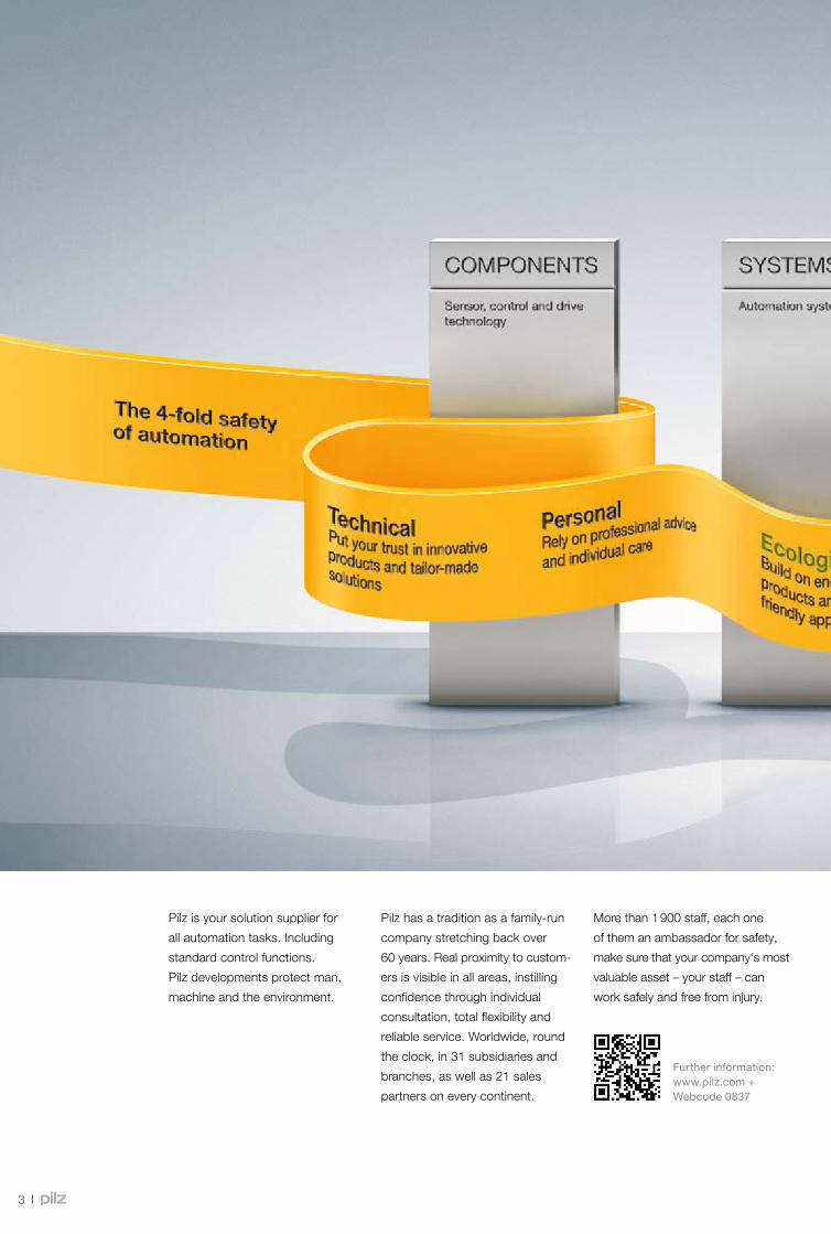
Pilz is your solution supplier for
all automation tasks. Including
standard control functions.
Pilz developments protect man,
machine and the environment.
Pilz has a tradition as a family-run
company stretching back over
60 years. Real proximity to custom-
ers is visible in all areas, instilling
confidence through individual
consultation, total flexibility and
reliable service. Worldwide, round
the clock, in 31 subsidiaries and
branches, as well as 21 sales
partners on every continent.
More than 1 900 staff, each one
of them an ambassador for safety,
make sure that your company‘s most
valuable asset – your staff – can
work safely and free from injury.
Further information: www.pilz.com + Webcode 0837
Automation solutions from Pilz – at home in every industry.

4
Pilz is your solution supplier for
all automation tasks. Including
standard control functions.
Pilz developments protect man,
machine and the environment.
Pilz has a tradition as a family-run
company stretching back over
60 years. Real proximity to custom-
ers is visible in all areas, instilling
confidence through individual
consultation, total flexibility and
reliable service. Worldwide, round
the clock, in 31 subsidiaries and
branches, as well as 21 sales
partners on every continent.
More than 1 900 staff, each one
of them an ambassador for safety,
make sure that your company‘s most
valuable asset – your staff – can
work safely and free from injury.
Further information: www.pilz.com + Webcode 0837
Automation solutions from Pilz – at home in every industry.

Pilz control technology – for safety and automation.
55
Pilz offers the right solution for every control technology situation. From stand-alone applications to networked and distributed systems – for safety and automation. Resolve your automation function economically, safely and from one source with compatible components and systems: from simple monitoring relays PMD to safety relays PNOZ, the configurable control systems PNOZmulti and the programmable control systems PSSuniversal PLC. As a result, a large number of applications can be implemented in compliance with the standards. Our software tools enable simple handling and make commissioning easier. Combine that with network components and software and you get complete automation architectures. Extensive diagnostic options mean you can benefit from short downtimes and high plant availability.
Control technology
Contents
Automation: complete and simple! 6
Control technology product area 8
Product group:
monitoring relays PMD
•Electronic monitoring relays PMDsigma 10
•Electronic monitoring relays PMDsrange 12
Product group:
safety relay PNOZ
•Safety relay PNOZsigma 18
•Safety relay PNOZ X 30
•Safety relay PNOZcompact 38
•Safety relay PNOZelog 40
•Safe line inspection device PLIDdys 48
•Safety relay PNOZpower 50
Product group: configurable
control systems PNOZmulti 56
•Configurable control systems PNOZmulti 2 60
•Configurable small control systems PNOZmulti Mini 68
•Configurable safety systems PNOZmulti 74
•Software tool PNOZmulti Configurator 84
•Accessories 86
Product group:
decentralised modules PDP67 and PDP20 88
•Cable navigator 90
Product group:
control systems and I/O systems PSSuniversal 92
•Control systems and I/O systems PSSuniversal 94
•Control systems and I/O systems
in the automation system PSS 4000 98
•Accessories 108
Did you know? 112
Services 114
Index 116
6
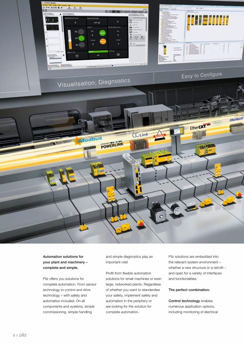
Automation solutions for
your plant and machinery –
complete and simple.
Pilz offers you solutions for
complete automation. From sensor
technology to control and drive
technology – with safety and
automation included. On all
components and systems, simple
commissioning, simple handling
and simple diagnostics play an
important role!
Profit from flexible automation
solutions for small machines or even
large, networked plants. Regardless
of whether you want to standardise
your safety, implement safety and
automation in the periphery or
are looking for the solution for
complete automation.
Pilz solutions are embedded into
the relevant system environment –
whether a new structure or a retrofit –
and open for a variety of interfaces
and functionalities.
The perfect combination:
Control technology enables
numerous application options,
including monitoring of electrical
7
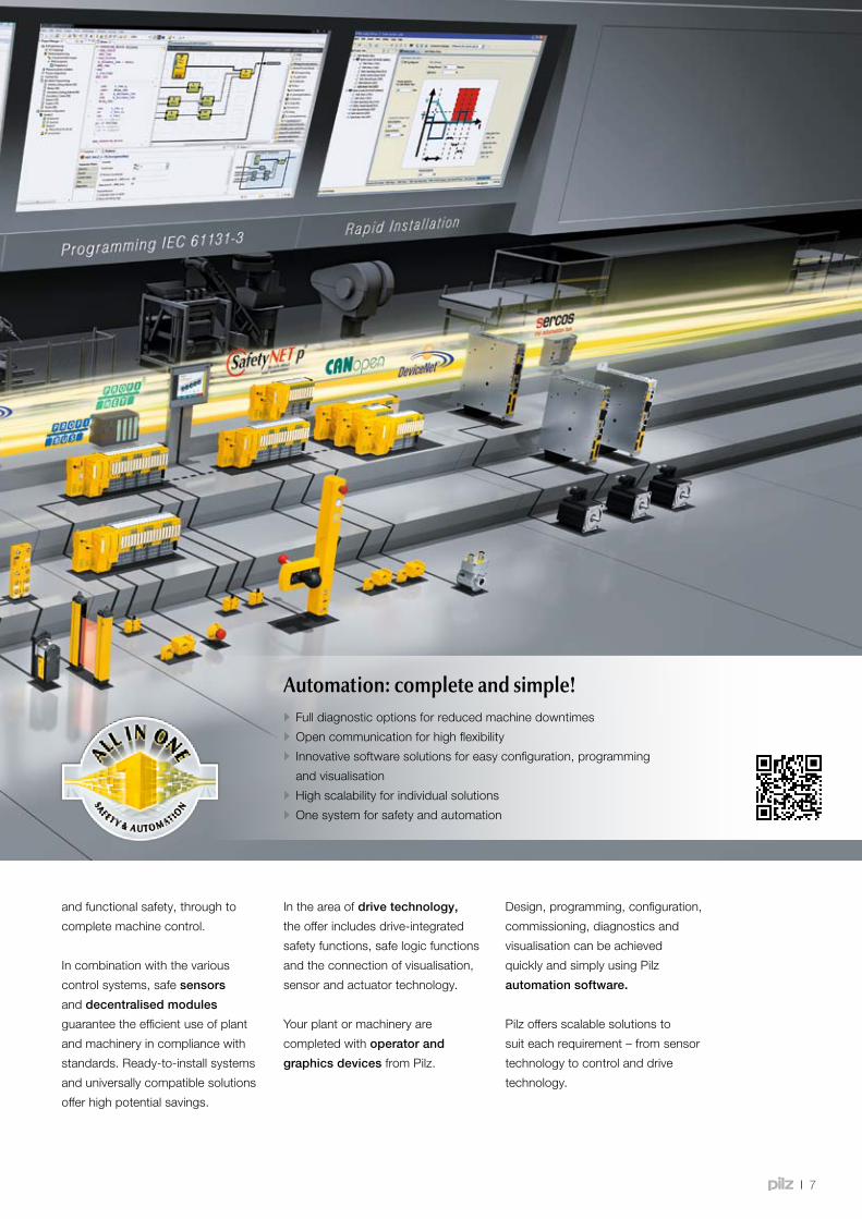
and functional safety, through to
complete machine control.
In combination with the various
control systems, safe sensors
and decentralised modules
guarantee the efficient use of plant
and machinery in compliance with
standards. Ready-to-install systems
and universally compatible solutions
offer high potential savings.
In the area of drive technology,
the offer includes drive-integrated
safety functions, safe logic functions
and the connection of visualisation,
sensor and actuator technology.
Your plant or machinery are
completed with operator and
graphics devices from Pilz.
Design, programming, configuration,
commissioning, diagnostics and
visualisation can be achieved
quickly and simply using Pilz
automation software.
Pilz offers scalable solutions to
suit each requirement – from sensor
technology to control and drive
technology.
• Full diagnostic options for reduced machine downtimes
• Open communication for high flexibility
• Innovative software solutions for easy configuration, programming
and visualisation
• High scalability for individual solutions
• One system for safety and automation
Automation: complete and simple!
6
Automation solutions for
your plant and machinery –
complete and simple.
Pilz offers you solutions for
complete automation. From sensor
technology to control and drive
technology – with safety and
automation included. On all
components and systems, simple
commissioning, simple handling
and simple diagnostics play an
important role!
Profit from flexible automation
solutions for small machines or even
large, networked plants. Regardless
of whether you want to standardise
your safety, implement safety and
automation in the periphery or
are looking for the solution for
complete automation.
Pilz solutions are embedded into
the relevant system environment –
whether a new structure or a retrofit –
and open for a variety of interfaces
and functionalities.
The perfect combination:
Control technology enables
numerous application options,
including monitoring of electrical
7
and functional safety, through to
complete machine control.
In combination with the various
control systems, safe sensors
and decentralised modules
guarantee the efficient use of plant
and machinery in compliance with
standards. Ready-to-install systems
and universally compatible solutions
offer high potential savings.
In the area of drive technology,
the offer includes drive-integrated
safety functions, safe logic functions
and the connection of visualisation,
sensor and actuator technology.
Your plant or machinery are
completed with operator and
graphics devices from Pilz.
Design, programming, configuration,
commissioning, diagnostics and
visualisation can be achieved
quickly and simply using Pilz
automation software.
Pilz offers scalable solutions to
suit each requirement – from sensor
technology to control and drive
technology.
• Full diagnostic options for reduced machine downtimes
• Open communication for high flexibility
• Innovative software solutions for easy configuration, programming
and visualisation
• High scalability for individual solutions
• One system for safety and automation
Automation: complete and simple!

000001 1.0
8
Pilz control technology – for safety and automa tion
ProductareaControltechnology
The optimum solution for every requirement – with these control systems and components you can implement each application in compliance with the standards. User-friendly software provides support when implementing your automation projects. From a stand-alone machine to networked plants – with Pilz your automation can be complete and simple.
With Pilz control technology you can implement:
•Simple machines with up to three safety functions
for monitoring E-STOPs, safety gates, light grids and
many more
•Complex stand-alone machines with high safety
requirements, such as presses, for example
•interlinked plants with a decentralised structure,
such as packaging machines, for example
•Complete lines with decentralised networking,
such as transfer lines, for example
Innovation is our motto! We work closely with
customers to continually develop the devices and
systems. Technologies such as the real-time Ethernet
SafetyNET p keep opening up new prospects in
control technology.
Standards for safety
Pilz’s thorough expertise in safety technology pays off.
Our control systems and decentralised periphery
modules meet the very highest safety requirements
and thus conform to international standards for
machine safety.
Relays Small control systems
Control technology requirements
Sm
all c
ontr
ol s
yste
ms
Rel
ays
PLC
con
trol
sys
tem
sD
ecen
tral
ised
I/O
sys
tem
s
PMDsigma
PNOZcompact
PNOZX
PNOZsigma
PNOZmulti2 PNOZmultiMini PNOZmulti
PNOZmultiConfigurator
9
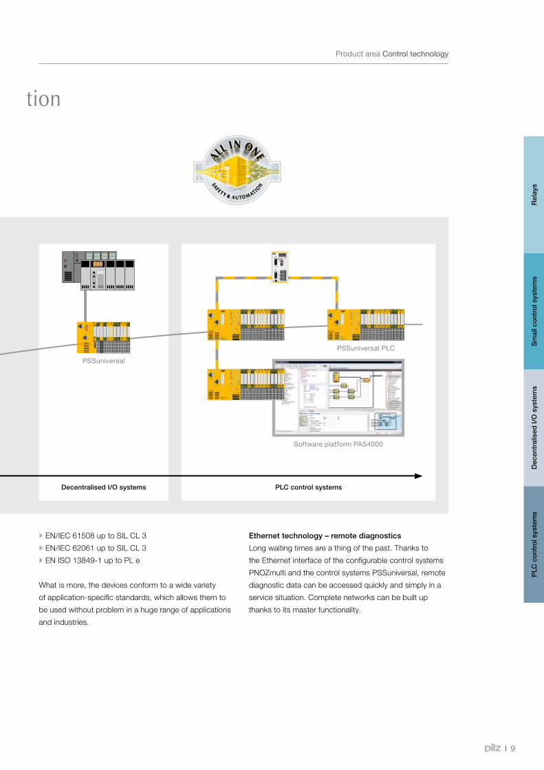
Pilz control technology – for safety and automa tion
ProductareaControltechnology
Ethernet technology – remote diagnostics
Long waiting times are a thing of the past. Thanks to
the Ethernet interface of the configurable control systems
PNOZmulti and the control systems PSSuniversal, remote
diagnostic data can be accessed quickly and simply in a
service situation. Complete networks can be built up
thanks to its master functionality.
Decentralised I/O systems PLC control systems
•EN/IEC 61508 up to SIL CL 3
•EN/IEC 62061 up to SIL CL 3
•EN ISO 13849-1 up to PL e
What is more, the devices conform to a wide variety
of application-specific standards, which allows them to
be used without problem in a huge range of applications
and industries.
Sm
all c
ontr
ol s
yste
ms
Rel
ays
PLC
con
trol
sys
tem
sD
ecen
tral
ised
I/O
sys
tem
s
PSSuniversal PLC
PSSuniversal
SoftwareplatformPAS4000
PMDs10
PMD s20
10
ProductrangeElectronicmonitoringrelaysPMDsigma
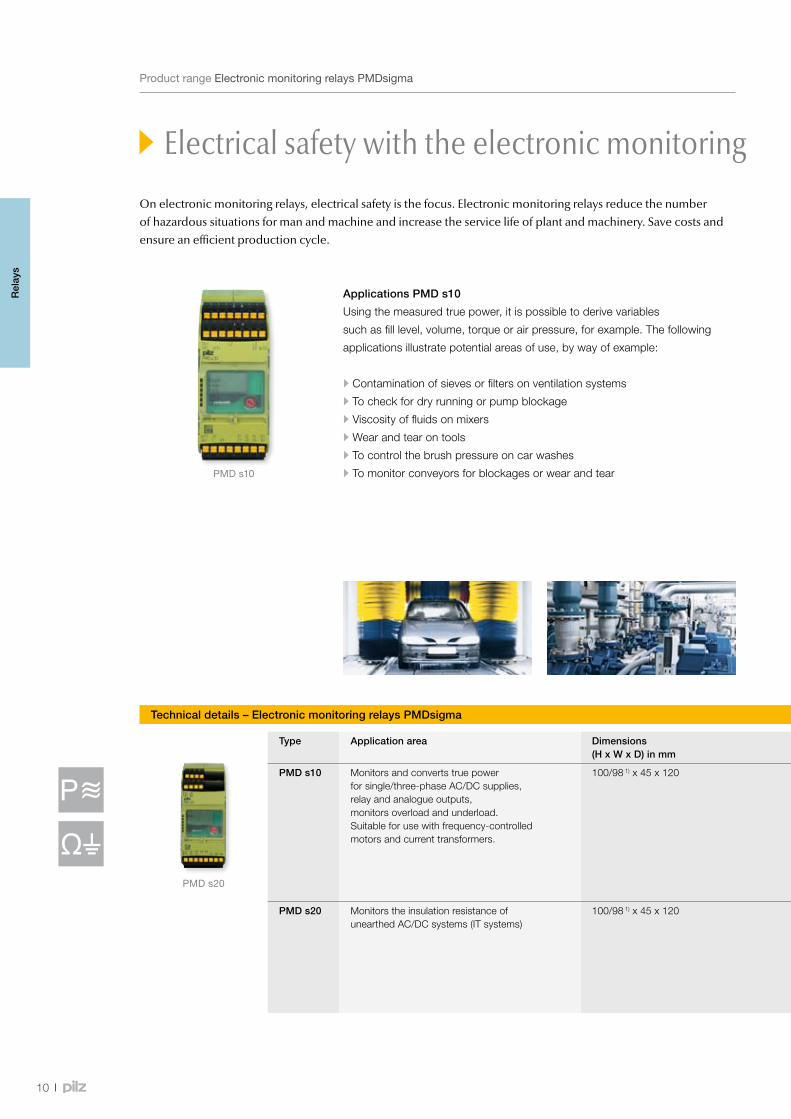
Electrical safety with the electronic monitoring relays PMDsigma
Applications PMD s10
Using the measured true power, it is possible to derive variables
such as fill level, volume, torque or air pressure, for example. The following
applications illustrate potential areas of use, by way of example:
•Contamination of sieves or filters on ventilation systems
•To check for dry running or pump blockage
•Viscosity of fluids on mixers
•Wear and tear on tools
•To control the brush pressure on car washes
•To monitor conveyors for blockages or wear and tear
Technical details – Electronic monitoring relays PMDsigma
Type Application area Dimensions (H x W x D) in mm
Features Order number
PMD s10 Monitors and converts true power for single/three-phase AC/DC supplies, relay and analogue outputs, monitors overload and underload. Suitable for use with frequency-controlled motors and current transformers.
100/98 1) x 45 x 120 • Measuring range is set automatically for current and voltage • Function parameter settings are menu-driven • Analogue outputs for current and voltage. Voltage output 0 … 10 V. Current output convertible from 0 … 20 mA to 4 … 20 mA.
• Relay outputs for monitoring underload and overload • Supply voltage (UB): 24 … 240 VAC/DC • Output contacts: 2 auxiliary contacts (C/O) • Measuring voltage (3 AC), UM (AC/DC): 100 … 550 V • Measuring current (IM): 1 … 12 A AC/DC
• Spring-loaded terminals PMD s10 C 761 100
• Plug-in screw terminals PMD s10 760 100
PMD s20 Monitors the insulation resistance of unearthed AC/DC systems (IT systems)
100/98 1) x 45 x 120 • Response value Ron: selectable from 10 … 200 kΩ • Voltage:
- Voltage supply via universal power supply: 24 … 240 VAC/DC - Measuring voltage of the IT system to be monitored: 0 … 400 VAC/DC
• Frequency range AC: 50 … 60 Hz • Start-up suppression/reaction time: selectable from 0 … 30 s • Hysteresis: selectable from 0 … 50 %
• Spring-loaded terminals PMD s20 C 761 120
• Plug-in screw terminals PMD s20 760 120
1)Heightwithspring-loadedterminals/plug-inscrewterminals
On electronic monitoring relays, electrical safety is the focus. Electronic monitoring relays reduce the number of hazardous situations for man and machine and increase the service life of plant and machinery. Save costs and ensure an efficient production cycle.
Rel
ays
11
Webcode 5215
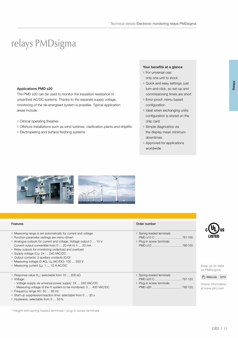
Electrical safety with the electronic monitoring relays PMDsigma
TechnicaldetailsElectronicmonitoringrelaysPMDsigma
Your benefits at a glance
•For universal use:
only one unit to stock
•Quick and easy settings, just
turn and click, so set-up and
commissioning times are short
•Error-proof: menu-based
configuration
•Ideal when exchanging units:
configuration is stored on the
chip card
•Simple diagnostics via
the display mean minimum
downtimes
•Approved for applications
worldwide
Applications PMD s20
The PMD s20 can be used to monitor the insulation resistance of
unearthed AC/DC systems. Thanks to the separate supply voltage,
monitoring of the de-energised system is possible. Typical application
areas include:
•Clinical operating theatres
•Offshore installations such as wind turbines, clarification plants and shiplifts
•Electroplating and surface finishing systems
Onlineinformationatwww.pilz.com
Keepup-to-dateonPMDsigma:
Technical details – Electronic monitoring relays PMDsigma
Type Application area Dimensions (H x W x D) in mm
Features Order number
PMD s10 Monitors and converts true power for single/three-phase AC/DC supplies, relay and analogue outputs, monitors overload and underload. Suitable for use with frequency-controlled motors and current transformers.
100/98 1) x 45 x 120 • Measuring range is set automatically for current and voltage • Function parameter settings are menu-driven • Analogue outputs for current and voltage. Voltage output 0 … 10 V. Current output convertible from 0 … 20 mA to 4 … 20 mA.
• Relay outputs for monitoring underload and overload • Supply voltage (UB): 24 … 240 VAC/DC • Output contacts: 2 auxiliary contacts (C/O) • Measuring voltage (3 AC), UM (AC/DC): 100 … 550 V • Measuring current (IM): 1 … 12 A AC/DC
• Spring-loaded terminals PMD s10 C 761 100
• Plug-in screw terminals PMD s10 760 100
PMD s20 Monitors the insulation resistance of unearthed AC/DC systems (IT systems)
100/98 1) x 45 x 120 • Response value Ron: selectable from 10 … 200 kΩ • Voltage:
- Voltage supply via universal power supply: 24 … 240 VAC/DC - Measuring voltage of the IT system to be monitored: 0 … 400 VAC/DC
• Frequency range AC: 50 … 60 Hz • Start-up suppression/reaction time: selectable from 0 … 30 s • Hysteresis: selectable from 0 … 50 %
• Spring-loaded terminals PMD s20 C 761 120
• Plug-in screw terminals PMD s20 760 120
1)Heightwithspring-loadedterminals/plug-inscrewterminals
Rel
ays
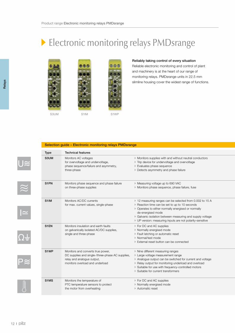
S3UM S1IM S1WP
12
ProductrangeElectronicmonitoringrelaysPMDsrange
Electronic monitoring relays PMDsrange
Reliably taking control of every situation
Reliable electronic monitoring and control of plant
and machinery is at the heart of our range of
monitoring relays. PMDsrange units in 22.5 mm
slimline housing cover the widest range of functions.
Selection guide – Electronic monitoring relays PMDsrange
Type Technical features Order number 1)
S3UM Monitors AC voltages for overvoltage and undervoltage, phase sequence/failure and asymmetry, three-phase
• Monitors supplies with and without neutral conductors • Trip device for undervoltage and overvoltage • Evaluates phase sequence • Detects asymmetry and phase failure
• Supply voltage (UB): AC: 120 V; DC: 24 V • Output contacts: 1 auxiliary contact (C/O) • Measuring voltage (3 AC) (UM): AC: 42, 230, 100/110, 400/440, 440/480, 415/460, 500/550 V, selectable
• Dimensions (H x W x D): 87 x 22.5 x 122 mm
• 24 VDC (UB), 230 VAC (UM) 837 260 • 24 VDC (UB), 400/440 VAC (UM) 837 270 • 24 VDC (UB), 415/460 VAC (UM) 837 280
S1PN Monitors phase sequence and phase failure on three-phase supplies
• Measuring voltage up to 690 VAC • Monitors phase sequence, phase failure, fuse
• Supply voltage (UB): AC: 200 … 240, 400 … 500, 550 … 690 V • Output contacts: 2 auxiliary contacts (2 C/O) • Dimensions (H x W x D): 87 x 22.5 x 121 mm
• 200 … 240 V 890 200 • 400 … 500 V 890 210 • 550 … 690 V 890 220
S1IM Monitors AC/DC currents for max. current values, single-phase
• 12 measuring ranges can be selected from 0.002 to 15 A • Reaction time can be set to up to 10 seconds • Operates to either normally energised or normally de-energised mode
• Galvanic isolation between measuring and supply voltage • UP version: measuring inputs are not polarity-sensitive
• Supply voltage (UB): AC: 24, 42 … 48, 110 … 127, 230 … 240 V; DC: 24 V • Output contacts: 1 auxiliary contact (C/O) • Dimensions (H x W x D): 87 x 22.5 x 121 mm
• 110 … 130 VAC (UB), 15 A (IM) 828 040 • 230 … 240 VAC (UB), 15 A (IM) 828 050 • 24 VDC (UB), 15 A (IM) 828 035
S1EN Monitors insulation and earth faults on galvanically isolated AC/DC supplies, single and three-phase
• For DC and AC supplies • Normally energised mode • Fault latching or automatic reset • Normal/test mode • External reset button can be connected
• Supply voltage (UB): AC/DC: 24 … 240 V • Output contacts: 1 auxiliary contact (C/O) • Rated mains voltage (monitored supply):
- 50 kΩ version: AC/DC: 0 … 240 V - 200 kΩ version: AC/DC: 0 … 400 V
• Dimensions (H x W x D): 87 x 22.5 x 121 mm
• 24 … 240 VAC/DC (UB), 50 kΩ 884 100 • 24 … 240 VAC/DC (UB), 200 kΩ 884 110
S1WP Monitors and converts true power, DC supplies and single-/three-phase AC supplies, relay and analogue output, monitors overload and underload
• Nine different measuring ranges • Large voltage measurement range • Analogue output can be switched for current and voltage • Relay output for monitoring underload and overload • Suitable for use with frequency-controlled motors • Suitable for current transformers
• Supply voltage (UB): DC: 24 V, AC/DC: 230 V • Output contacts: 1 auxiliary contact (C/O) • Measuring voltage: 3 AC/1 AC/DC: 0 … 70, 0 … 120, 0 … 140, 0 … 240, 0 … 320, 0 … 415, 0 … 550 V
• Dimensions (H x W x D): 87 x 22.5 x 121 mm
• 9 A (IM), 24 VDC (UB), 0 … 240 VAC/DC 890 010
• 9 A (IM), 24 VDC (UB), 0 … 415 VAC/DC 890 020
• 9 A (IM), 24 VDC (UB), 0 … 550 VAC/DC 890 030
S1MS Monitors the temperature of PTC temperature sensors to protect the motor from overheating
• For DC and AC supplies • Normally energised mode • Automatic reset
• Supply voltage (UB): AC: 48, 110, 230, 240, 400 V; AC/DC: 24 V • Output contacts: 2 auxiliary contacts (2 C/O) • Dimensions (H x W x D): 87 x 22.5 x 121 mm
• 24 VAC/DC (UB) 840 775 • 230 VAC (UB) 840 760 • 400 VAC (UB) 840 770
1)Additionalversionsonrequest Ordernumberfeatures:UB=Supplyvoltage;UM=Measuringvoltage;IM=Measuringcurrent
Rel
ays
13
Webcode 5219
Electronic monitoring relays PMDsrange
TechnicaldetailsElectronicmonitoringrelaysPMDsrange
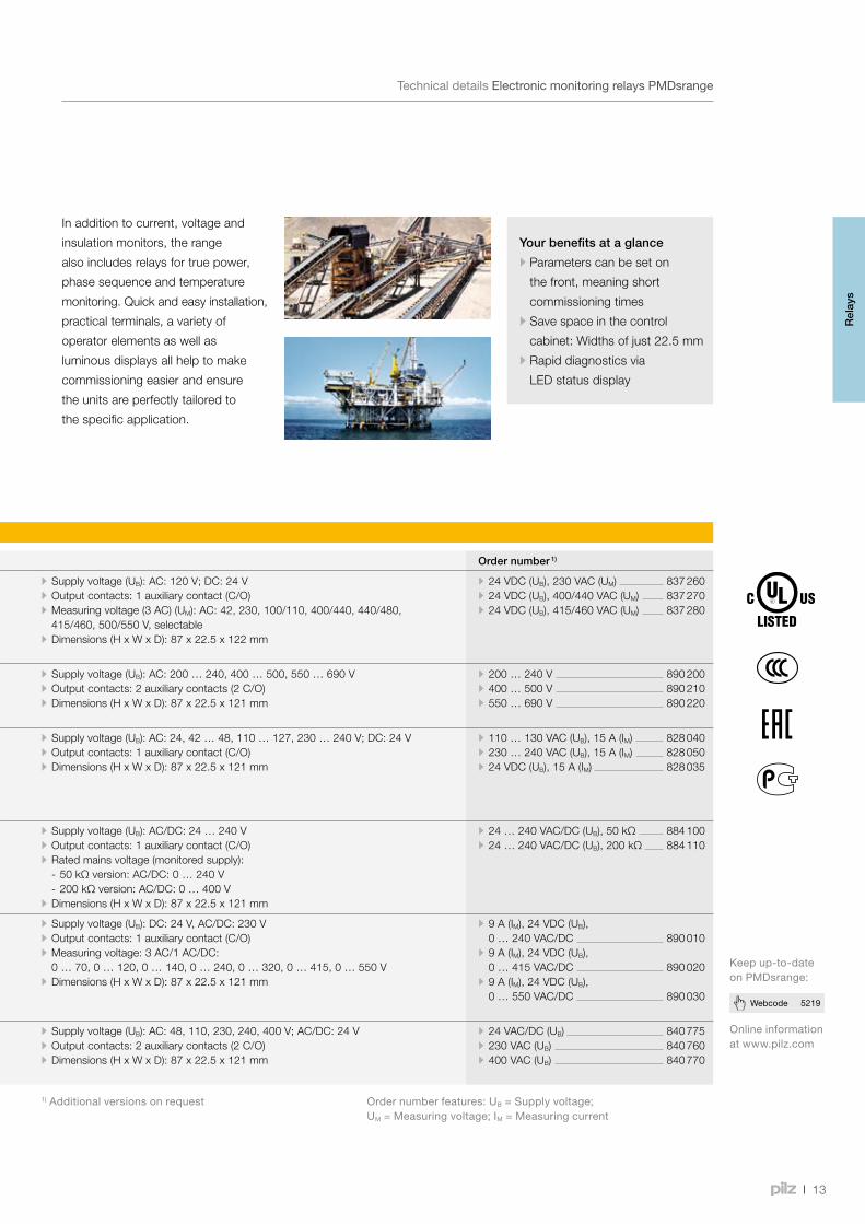
Your benefits at a glance
•Parameters can be set on
the front, meaning short
commissioning times
•Save space in the control
cabinet: Widths of just 22.5 mm
•Rapid diagnostics via
LED status display
In addition to current, voltage and
insulation monitors, the range
also includes relays for true power,
phase sequence and temperature
monitoring. Quick and easy installation,
practical terminals, a variety of
operator elements as well as
luminous displays all help to make
commissioning easier and ensure
the units are perfectly tailored to
the specific application.
Selection guide – Electronic monitoring relays PMDsrange
Type Technical features Order number 1)
S3UM Monitors AC voltages for overvoltage and undervoltage, phase sequence/failure and asymmetry, three-phase
• Monitors supplies with and without neutral conductors • Trip device for undervoltage and overvoltage • Evaluates phase sequence • Detects asymmetry and phase failure
• Supply voltage (UB): AC: 120 V; DC: 24 V • Output contacts: 1 auxiliary contact (C/O) • Measuring voltage (3 AC) (UM): AC: 42, 230, 100/110, 400/440, 440/480, 415/460, 500/550 V, selectable
• Dimensions (H x W x D): 87 x 22.5 x 122 mm
• 24 VDC (UB), 230 VAC (UM) 837 260 • 24 VDC (UB), 400/440 VAC (UM) 837 270 • 24 VDC (UB), 415/460 VAC (UM) 837 280
S1PN Monitors phase sequence and phase failure on three-phase supplies
• Measuring voltage up to 690 VAC • Monitors phase sequence, phase failure, fuse
• Supply voltage (UB): AC: 200 … 240, 400 … 500, 550 … 690 V • Output contacts: 2 auxiliary contacts (2 C/O) • Dimensions (H x W x D): 87 x 22.5 x 121 mm
• 200 … 240 V 890 200 • 400 … 500 V 890 210 • 550 … 690 V 890 220
S1IM Monitors AC/DC currents for max. current values, single-phase
• 12 measuring ranges can be selected from 0.002 to 15 A • Reaction time can be set to up to 10 seconds • Operates to either normally energised or normally de-energised mode
• Galvanic isolation between measuring and supply voltage • UP version: measuring inputs are not polarity-sensitive
• Supply voltage (UB): AC: 24, 42 … 48, 110 … 127, 230 … 240 V; DC: 24 V • Output contacts: 1 auxiliary contact (C/O) • Dimensions (H x W x D): 87 x 22.5 x 121 mm
• 110 … 130 VAC (UB), 15 A (IM) 828 040 • 230 … 240 VAC (UB), 15 A (IM) 828 050 • 24 VDC (UB), 15 A (IM) 828 035
S1EN Monitors insulation and earth faults on galvanically isolated AC/DC supplies, single and three-phase
• For DC and AC supplies • Normally energised mode • Fault latching or automatic reset • Normal/test mode • External reset button can be connected
• Supply voltage (UB): AC/DC: 24 … 240 V • Output contacts: 1 auxiliary contact (C/O) • Rated mains voltage (monitored supply):
- 50 kΩ version: AC/DC: 0 … 240 V - 200 kΩ version: AC/DC: 0 … 400 V
• Dimensions (H x W x D): 87 x 22.5 x 121 mm
• 24 … 240 VAC/DC (UB), 50 kΩ 884 100 • 24 … 240 VAC/DC (UB), 200 kΩ 884 110
S1WP Monitors and converts true power, DC supplies and single-/three-phase AC supplies, relay and analogue output, monitors overload and underload
• Nine different measuring ranges • Large voltage measurement range • Analogue output can be switched for current and voltage • Relay output for monitoring underload and overload • Suitable for use with frequency-controlled motors • Suitable for current transformers
• Supply voltage (UB): DC: 24 V, AC/DC: 230 V • Output contacts: 1 auxiliary contact (C/O) • Measuring voltage: 3 AC/1 AC/DC: 0 … 70, 0 … 120, 0 … 140, 0 … 240, 0 … 320, 0 … 415, 0 … 550 V
• Dimensions (H x W x D): 87 x 22.5 x 121 mm
• 9 A (IM), 24 VDC (UB), 0 … 240 VAC/DC 890 010
• 9 A (IM), 24 VDC (UB), 0 … 415 VAC/DC 890 020
• 9 A (IM), 24 VDC (UB), 0 … 550 VAC/DC 890 030
S1MS Monitors the temperature of PTC temperature sensors to protect the motor from overheating
• For DC and AC supplies • Normally energised mode • Automatic reset
• Supply voltage (UB): AC: 48, 110, 230, 240, 400 V; AC/DC: 24 V • Output contacts: 2 auxiliary contacts (2 C/O) • Dimensions (H x W x D): 87 x 22.5 x 121 mm
• 24 VAC/DC (UB) 840 775 • 230 VAC (UB) 840 760 • 400 VAC (UB) 840 770
1)Additionalversionsonrequest Ordernumberfeatures:UB=Supplyvoltage;UM=Measuringvoltage;IM=Measuringcurrent
Onlineinformationatwww.pilz.com
Keepup-to-dateonPMDsrange:
Rel
ays
PNOZsigma
000001 1.0 000001 1.0
PowerIn 1In 2Out 1Out 2Fault
PNOZ s30
750330000001 1.0
PNOZ X
PNOZcompact
PNOZelogA1 S32 Y37 S42
P2
POWER
CH. 1
CH. 2
14 24 Y33 Y5P1
A2 S34 S36 Y32P2
S12 S22 Y6 Y7 P1
PNOZ e8.1p
7741
9800
0003
1.0
PNOZpower
14
Safety relay PNOZ®
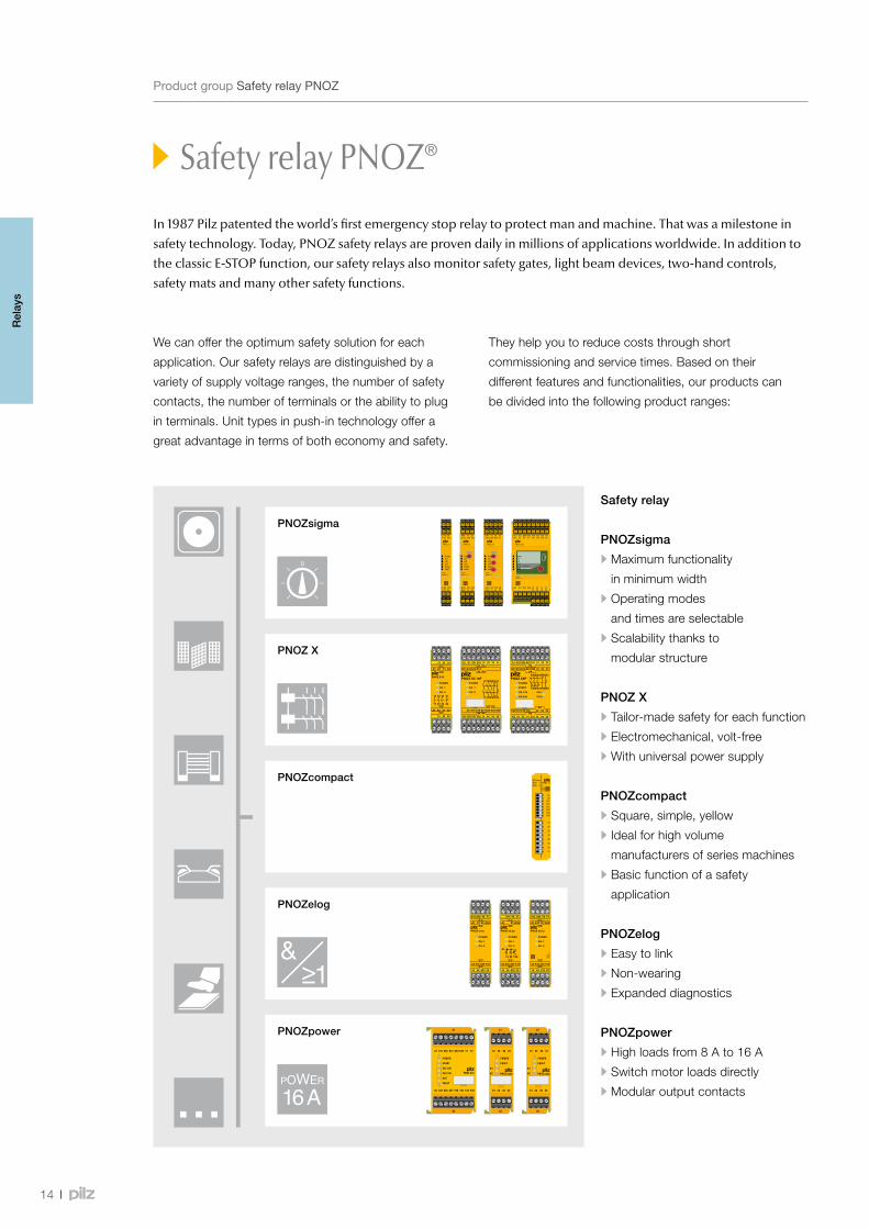
In 1987 Pilz patented the world’s first emergency stop relay to protect man and machine. That was a milestone in safety technology. Today, PNOZ safety relays are proven daily in millions of applications worldwide. In addition to the classic E-STOP function, our safety relays also monitor safety gates, light beam devices, two-hand controls, safety mats and many other safety functions.
We can offer the optimum safety solution for each
application. Our safety relays are distinguished by a
variety of supply voltage ranges, the number of safety
contacts, the number of terminals or the ability to plug
in terminals. Unit types in push-in technology offer a
great advantage in terms of both economy and safety.
They help you to reduce costs through short
commissioning and service times. Based on their
different features and functionalities, our products can
be divided into the following product ranges:
Safety relay
PNOZsigma
•Maximum functionality
in minimum width
•Operating modes
and times are selectable
•Scalability thanks to
modular structure
PNOZ X
•Tailor-made safety for each function
•Electromechanical, volt-free
•With universal power supply
PNOZcompact
•Square, simple, yellow
•Ideal for high volume
manufacturers of series machines
•Basic function of a safety
application
PNOZelog
•Easy to link
•Non-wearing
•Expanded diagnostics
PNOZpower
•High loads from 8 A to 16 A
•Switch motor loads directly
•Modular output contacts
ProductgroupSafetyrelayPNOZ
Rel
ays

000001 1.0 000001 1.0
PowerIn 1In 2Out 1Out 2Fault
PNOZ s30
750330000001 1.0
A1 S32 Y37 S42P2
POWER
CH. 1
CH. 2
14 24 Y33 Y5P1
A2 S34 S36 Y32P2
S12 S22 Y6 Y7 P1
PNOZ e8.1p
7741
9800
0003
1.0
15
Finding your PNOZThisdiagramwillhelpyoutochoose.Youhavespecificrequirements,wehavetherightsolution.
Morethanthreesafetyfunctions/configurable?
Breakingcapacity>8 A?
PNOZmultiFurtherinformationfrompage74
PNOZpowerFurtherinformationfrompage50
Goodscalability/user-friendlydiagnostics?
PNOZsigmaFurtherinformationfrompage18
PNOZelogFurtherinformationfrompage40
PNOZ XFurtherinformationfrompage30
PNOZcompactFurtherinformationfrompage38
AbilitytoconnectsafetyfunctionsviaAND/ORlogic
Plug-interminals/universalpowersupply?
Yes
No
No
Yes
No
Yes
No
Safety relay PNOZ®
Yes
PNOZmulti MiniFurtherinformationfrompage68
PNOZmulti 2Furtherinformationfrompage60
PNOZmulti ConfiguratorFurtherinformationfrompage58
No
Yes
ProductgroupSafetyrelayPNOZ
Rel
ays
ISOANSIIEC
EN
SIL
SIL
IEC
ISO
PL
PL
16
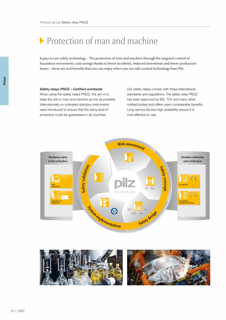
Safety relays PNOZ – Certified worldwide
When using the safety relays PNOZ, the aim is to
keep the risk to man and machine as low as possible.
Internationally co-ordinated statutory instruments
were introduced to ensure that the same level of
protection could be guaranteed in all countries.
It pays to use safety technology – The protection of man and machine through the targeted control of hazardous movements, cost savings thanks to fewer accidents, reduced downtimes and fewer production losses – these are real benefits that you can enjoy when you use safe control technology from Pilz.
Protection of man and machine
Our safety relays comply with these international
standards and regulations. The safety relay PNOZ
has been approved by BG, TÜV and many other
notified bodies and offers users considerable benefits.
Long service life and high availability ensure it is
cost-effective to use.
Machinery safety in the work place
Machine conformity and certification
Inspection of safeguards
Internationalcompliance services
Plantassessment
CE marking
System implementation Safety desig
n
Safe
ty va
lidat
ion
Risk assessment
Safety concept
Rel
ays
ProductgroupSafetyrelayPNOZ
Geringes Risiko
Hohes Risiko
S1
S2
F1
F2
F1
F2
P1
P1
P2
P2
P1
P1
P2
P2
a
e
d
c
b
17
Webcode 0240
Your benefits at a glance
The use of safety relays PNOZ
offers you:
•The security and innovative
strength of one of the leading
brands in automation technology
•The appropriate solution for
each application
•High plant availability thanks
to user-friendly diagnostics
•Low downtimes for your plant
or machinery
•Optimum cost/performance
ratio
•Faster commissioning,
for example, through units
with plug-in terminals
•Maximum safety with minimum
space requirement
•Simple wiring,
fast commissioning
•A solid partner with expertise
•Certified safety, because
our products comply with
international standards and
regulations and have been
tested and approved worldwide
•Quality guarantee, we are
certified to DIN ISO 9001
•Use of products that are
geared towards the future,
thanks to innovative
developments
•Complete solution comprising
evaluation devices, compatible
sensor technology and control
and signal devices
Onlineinformationatwww.pilz.com
Findoutmoreaboutthestandards:
Protection of man and machine
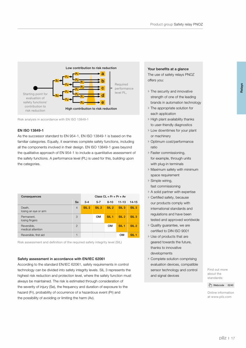
EN ISO 13849-1
As the successor standard to EN 954-1, EN ISO 13849-1 is based on the
familiar categories. Equally, it examines complete safety functions, including
all the components involved in their design. EN ISO 13849-1 goes beyond
the qualitative approach of EN 954-1 to include a quantitative assessment of
the safety functions. A performance level (PL) is used for this, building upon
the categories.
RiskanalysisinaccordancewithEN ISO 13849-1
Safety assessment in accordance with EN/IEC 62061
According to the standard EN/IEC 62061, safety requirements in control
technology can be divided into safety integrity levels. SIL 3 represents the
highest risk reduction and protection level, where the safety function must
always be maintained. The risk is estimated through consideration of
the severity of injury (Se), the frequency and duration of exposure to the
hazard (Fr), probability of occurrence of a hazardous event (Pr) and
the possibility of avoiding or limiting the harm (Av).
Riskassessmentanddefinitionoftherequiredsafetyintegritylevel(SIL)
High contribution to risk reduction
Low contribution to risk reduction
RequiredperformancelevelPLrStartingpointfor
evaluationofsafetyfunctions’contributiontoriskreduction
Consequences Class CL = Fr + Pr + Av
Se 3-4 5-7 8-10 11-13 14-15
Death, losing an eye or arm
4 SIL 2 SIL 2 SIL 2 SIL 3 SIL 3
Permanent, losing fingers
3 OM SIL 1 SIL 2 SIL 3
Reversible, medical attention
2 OM SIL 1 SIL 2
Reversible, first aid 1 OM SIL 1
Rel
ays
ProductgroupSafetyrelayPNOZ
PNOZ s5PNOZ s3PNOZ s1 PNOZ s30
PowerIn 1In 2Out 1Out 2Fault
PNOZ s30
750330000001 1.0
000001 1.0
000001 1.0
000001 1.0 000001 1.0
PNOZ s3+PNOZ s7.1/s7.2
PNOZ s30+PNOZ s22
PMD s10 PNOZ s6
PNOZ s5
PNOZ s4
18
ProductrangeSafetyrelaysPNOZsigma
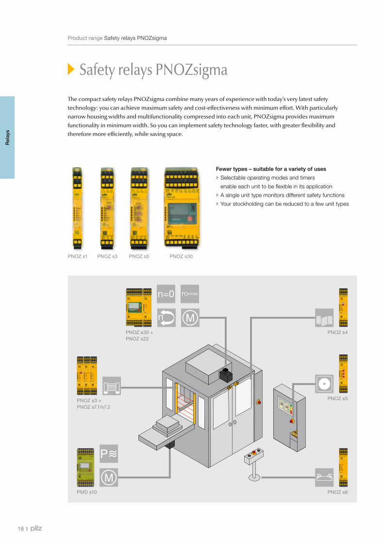
Safety relays PNOZsigma
The compact safety relays PNOZsigma combine many years of experience with today’s very latest safety technology: you can achieve maximum safety and cost-effectiveness with minimum effort. With particularly narrow housing widths and multifunctionality compressed into each unit, PNOZsigma provides maximum functionality in minimum width. So you can implement safety technology faster, with greater flexibility and therefore more efficiently, while saving space.
Fewer types – suitable for a variety of uses
•Selectable operating modes and timers
enable each unit to be flexible in its application
•A single unit type monitors different safety functions
•Your stockholding can be reduced to a few unit types
Rel
ays
000001 1.0
max
min
000001 1.0 000001 1.0
19
Webcode 5229
Safety relays PNOZsigma
BenefitsataglanceSafetyrelaysPNOZsigma
Your benefits at a glance
•Narrower widths save
space within the control
cabinet, and therefore costs!
•Reduce wiring costs through
push-in technology and
expand the number of contacts
via connectors
•Rapid commissioning and
high availability
•Low logistics costs: few unit
types to stock, covering many
safety functions
•Use the complete solution
from Pilz and supplement the
PNOZsigma with compatible,
approved safety components:
from E-STOP pushbuttons to
safe sensors such as safety
switches and light curtains,
through to operator terminals
for diagnostics and visualisation
Onlineinformationatwww.pilz.com
Keepup-to-dateonsafetyrelaysPNOZsigma:
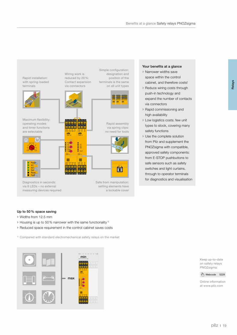
Wiringworkisreducedby20%:Contactexpansionviaconnectors
Rapidinstallation:withspring-loadedterminals
Simpleconfiguration:designationandpositionofthe
terminalsisthesameonallunittypes
Maximumflexibility:operatingmodesandtimerfunctionsareselectable
Rapidassemblyviaspringclips:
noneedfortools
Diagnosticsinseconds:via6LEDs–noexternalmeasuringdevicesrequired
Safefrommanipulation:settingelementshave
alockablecover
Up to 50 % space saving
•Widths from 12.5 mm
•Housing is up to 50 % narrower with the same functionality 1)
•Reduced space requirement in the control cabinet saves costs
1) Comparedwithstandardelectromechanicalsafetyrelaysonthemarket
Rel
ays

PowerIn 1In 2Out 1Out 2Fault
PNOZ s30
750330000001 1.0
20
Webcode 5229
ProductfeaturesSafetyrelaysPNOZsigma
Onlineinformationatwww.pilz.com
Keepup-to-dateonsafetyrelaysPNOZsigma:
Convenient speed monitoring
Safe speed monitor PNOZ s30
Convenient speed monitoring – the speed monitor PNOZ s30 provides
safe monitoring of standstill, speed, direction of rotation and shear pin
breakage. For example, travelling at reduced speed during set-up mode
increases operator safety. Productivity is increased, as an unnecessary
shutdown is prevented. This all saves costs and protects machinery as well
as staff. It also enables you to comply with the requirement of the new
Machinery Directive, which states that in the field of drive monitoring, the
operating status must be safely monitored and maintained when the drive
is brought to a standstill. Typical applications are pleasure parks, balancing
machines, high bay racking, centrifuges, filling machines, machining centres,
wind turbines.
Your benefits at a glance
•Increased productivity and
safety for operating personnel
•Productivity is increased
by avoiding unnecessary
shutdown processes:
advance warning is given
when a defined warning
threshold is reached
•Save time during setup and
when units are exchanged,
thanks to convenient operation
via rotary knob (push and turn)
•Suitable for all common
motor feedback systems
and proximity switches
•Contact expansion module
PNOZ s22: Duplication of
the relay contacts enables the
application’s function range
to be expanded
Contact expansion module
PNOZ s22 – Twice as good
PNOZ s22 provides two relay
functions that can be controlled
separately in accordance with
PL e of EN ISO 13849-1. Each
relay function provides 3 N/O/1 N/C
contacts. These can be controlled
separately, so that the outputs
can be assigned different functions,
depending on the base unit. Safe
separation between the two relay
functions enables different potentials
to be switched.
RelaycontactscanbemultipliedbycombiningPNOZs22andPNOZs30.
Rel
ays
000001 1.0 000001 1.0 000001 1.0 000001 1.0 000001 1.0
PNOZ s7.2PNOZ s3 + PNOZ s7.1 + + PNOZ s7.2
… 102
000001 1.0
000001 1.0
21
ProductfeaturesSafetyrelaysPNOZsigma
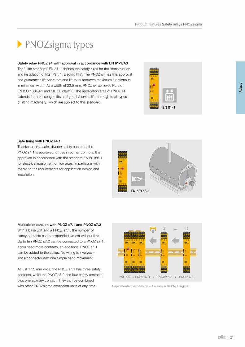
Multiple expansion with PNOZ s7.1 and PNOZ s7.2
With a base unit and a PNOZ s7.1, the number of
safety contacts can be expanded almost without limit.
Up to ten PNOZ s7.2 can be connected to a PNOZ s7.1.
If you need more contacts, an additional PNOZ s7.1
can be added to the series. No wiring is involved –
just a connector and one simple hand movement.
At just 17.5 mm wide, the PNOZ s7.1 has three safety
contacts, while the PNOZ s7.2 has four safety contacts
plus one auxiliary contact. They can be combined
with other PNOZsigma expansion units at any time. Rapidcontactexpansion–it’seasywithPNOZsigma!
Safety relay PNOZ s4 with approval in accordance with EN 81-1/A3
The "Lifts standard" EN 81-1 defines the safety rules for the “construction
and installation of lifts; Part 1: Electric lifts”. The PNOZ s4 has this approval
and guarantees lift operators and lift manufacturers maximum functionality
in minimum width. At a width of 22.5 mm, PNOZ s4 achieves PL e of
EN ISO 13849-1 and SIL CL claim 3. The application area of PNOZ s4
extends from passenger lifts and goods/service lifts through to all types
of lifting machinery, which are subject to this standard.
Safe firing with PNOZ s4.1
Thanks to three safe, diverse safety contacts, the
PNOZ s4.1 is approved for use in burner controls. It is
approved in accordance with the standard EN 50156-1
for electrical equipment on furnaces, in particular with
regard to the requirements for application design and
installation.
PNOZsigma types
Rel
ays
PNOZ s50
PNOZ s50
22
ProductfeaturesSafetyrelaysPNOZsigma
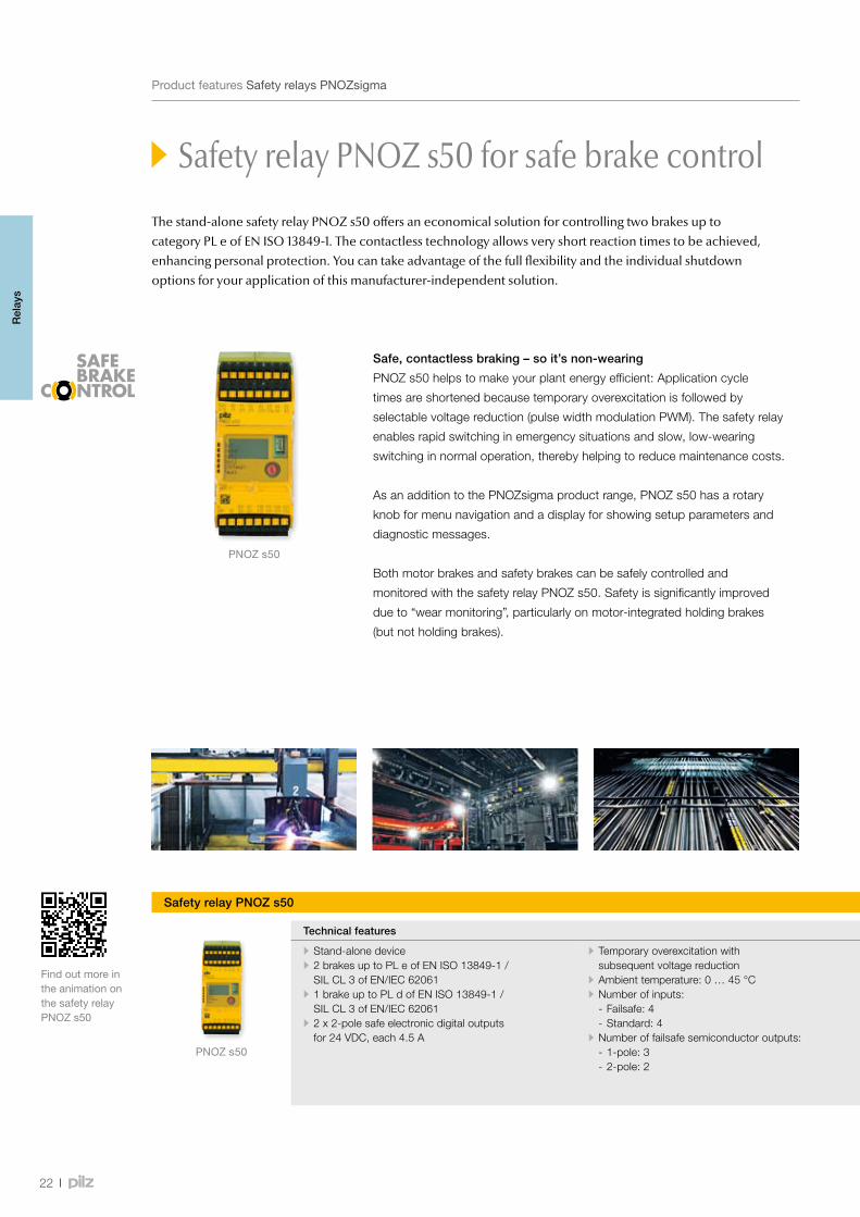
The stand-alone safety relay PNOZ s50 offers an economical solution for controlling two brakes up to category PL e of EN ISO 13849-1. The contactless technology allows very short reaction times to be achieved, enhancing personal protection. You can take advantage of the full flexibility and the individual shutdown options for your application of this manufacturer-independent solution.
Safe, contactless braking – so it’s non-wearing
PNOZ s50 helps to make your plant energy efficient: Application cycle
times are shortened because temporary overexcitation is followed by
selectable voltage reduction (pulse width modulation PWM). The safety relay
enables rapid switching in emergency situations and slow, low-wearing
switching in normal operation, thereby helping to reduce maintenance costs.
As an addition to the PNOZsigma product range, PNOZ s50 has a rotary
knob for menu navigation and a display for showing setup parameters and
diagnostic messages.
Both motor brakes and safety brakes can be safely controlled and
monitored with the safety relay PNOZ s50. Safety is significantly improved
due to “wear monitoring”, particularly on motor-integrated holding brakes
(but not holding brakes).
FindoutmoreintheanimationonthesafetyrelayPNOZ s50
Safety relay PNOZ s50 for safe brake control
Safety relay PNOZ s50
Technical features Order number
• Stand-alone device • 2 brakes up to PL e of EN ISO 13849-1 / SIL CL 3 of EN/IEC 62061
• 1 brake up to PL d of EN ISO 13849-1 / SIL CL 3 of EN/IEC 62061
• 2 x 2-pole safe electronic digital outputs for 24 VDC, each 4.5 A
• Temporary overexcitation with subsequent voltage reduction
• Ambient temperature: 0 … 45 °C • Number of inputs:
- Failsafe: 4 - Standard: 4
• Number of failsafe semiconductor outputs: - 1-pole: 3 - 2-pole: 2
• Supply voltage: - 1-pole: 24 VDC - 2-pole: 24 VDC, 48 VDC
• Voltage tolerance: - 1-pole: -15 % … +20 % - 2-pole: -10 % … +10 %
• Output current of semiconductor outputs (1-pole): 0.1 A
• Test pulse outputs – semiconductor outputs (1-pole): 2
• Reduced voltage of semiconductor outputs (2-pole): 6 V, 8 V, 12 V, 16 V, 24 V
• Output current of semiconductor outputs (2-pole): - 24 VDC supply voltage: Continuous duty (1 output/2 outputs): 1 x 6.5 A/2 x 4.5 A Overexcitation (1 output/2 outputs): 1 x 6.5 A/ ∑ = 10
- 48 VDC supply voltage: Continuous duty (1 output/2 outputs): 1 x 3.25 A/2 x 2.25 A Overexcitation (1 output/2 outputs): 1 x 3.25 A/2 x 3.25 A
751 500 (with spring-loaded terminals)
Rel
ays

23
Webcode 5229
Safety relay PNOZ s50 for safe brake control
Safety relay PNOZ s50
Technical features Order number
• Stand-alone device • 2 brakes up to PL e of EN ISO 13849-1 / SIL CL 3 of EN/IEC 62061
• 1 brake up to PL d of EN ISO 13849-1 / SIL CL 3 of EN/IEC 62061
• 2 x 2-pole safe electronic digital outputs for 24 VDC, each 4.5 A
• Temporary overexcitation with subsequent voltage reduction
• Ambient temperature: 0 … 45 °C • Number of inputs:
- Failsafe: 4 - Standard: 4
• Number of failsafe semiconductor outputs: - 1-pole: 3 - 2-pole: 2
• Supply voltage: - 1-pole: 24 VDC - 2-pole: 24 VDC, 48 VDC
• Voltage tolerance: - 1-pole: -15 % … +20 % - 2-pole: -10 % … +10 %
• Output current of semiconductor outputs (1-pole): 0.1 A
• Test pulse outputs – semiconductor outputs (1-pole): 2
• Reduced voltage of semiconductor outputs (2-pole): 6 V, 8 V, 12 V, 16 V, 24 V
• Output current of semiconductor outputs (2-pole): - 24 VDC supply voltage: Continuous duty (1 output/2 outputs): 1 x 6.5 A/2 x 4.5 A Overexcitation (1 output/2 outputs): 1 x 6.5 A/ ∑ = 10
- 48 VDC supply voltage: Continuous duty (1 output/2 outputs): 1 x 3.25 A/2 x 2.25 A Overexcitation (1 output/2 outputs): 1 x 3.25 A/2 x 3.25 A
751 500 (with spring-loaded terminals)
ProductfeaturesSafetyrelaysPNOZsigma
Your benefits at a glance
•Highest level of safety up to
PL e when controlling 2 brakes
(holding brakes or safety brakes)
•Contactless technology
up to 4.5 A per brake
enables short reaction times,
a long-lasting solution and
high availability
•Reduced cycle times through
temporary overexcitation with
subsequent voltage reduction
•High safety and low wear on
the brake thanks to fast
and slow shutdown of the
power circuits
•Rapid diagnostics by means
of display
•Manufacturer-independent
brake control thanks to safe,
digital inputs
Inmanyapplicationsitisnecessarytosafeguardanadditionalbrakealongsidetheholdingbrake.Inthefieldofstagetechnology,forexample,winchesareoperatedwithadualbrake.
Onlineinformationatwww.pilz.com
TechnicaldocumentationonsafetyrelaysPNOZs50:
Rel
ays

24
SelectionguideSafetyrelaysPNOZsigma
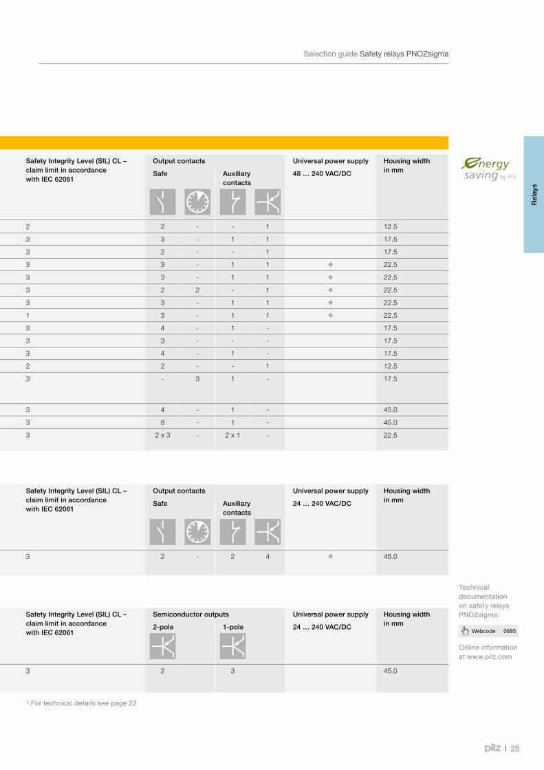
Safety relays PNOZsigma
Type Application Performance Level (PL) – EN ISO 13849-1
Safety Integrity Level (SIL) CL – claim limit in accordance with IEC 62061
Output contacts Universal power supply Housing widthin mmSafe Auxiliary
contacts 48 … 240 VAC/DC
PNOZ s1 c 2 2 - - 1 12.5
PNOZ s2 e 3 3 - 1 1 17.5
PNOZ s3 e 3 2 - - 1 17.5
PNOZ s4 e 3 3 - 1 1 22.5
PNOZ s4.1 e 3 3 - 1 1 22.5
PNOZ s5 e 3 2 2 - 1 22.5
PNOZ s6 EN 574, Type IIIC e 3 3 - 1 1 22.5
PNOZ s6.1 EN 574, Type IIIA c 1 3 - 1 1 22.5
PNOZ s7 Contact expansion e 3 4 - 1 - 17.5
PNOZ s7.1 Contact expansion e 3 3 - - - 17.5
PNOZ s7.2 Contact expansion e 3 4 - 1 - 17.5
PNOZ s8 Contact expansion c 2 2 - - 1 12.5
PNOZ s9 Contact expansion or safe timer relay
e 3 - 3 1 - 17.5
PNOZ s10 Contact expansion e 3 4 - 1 - 45.0
PNOZ s11 Contact expansion e 3 8 - 1 - 45.0
PNOZ s22 Contact expansion for PNOZ s30 and PNOZ mm0.1p/mm0.2p
e 3 2 x 3 - 2 x 1 - 22.5
Type Application Performance Level (PL) – EN ISO 13849-1
Safety Integrity Level (SIL) CL – claim limit in accordance with IEC 62061
Output contacts Universal power supply Housing widthin mmSafe Auxiliary
contacts24 … 240 VAC/DC
PNOZ s30 Safe speed and standstill monitor e 3 2 - 2 4 45.0
Type Application Performance Level (PL) – EN ISO 13849-1
Safety Integrity Level (SIL) CL – claim limit in accordance with IEC 62061
Semiconductor outputs Universal power supply Housing widthin mm2-pole 1-pole 24 … 240 VAC/DC
PNOZ s50 1) Safe brake control e 3 2 3 45.0
1)Fortechnicaldetailsseepage22
Selection guide – PNOZsigma
Rel
ays
25
Webcode 0685
SelectionguideSafetyrelaysPNOZsigma
Safety relays PNOZsigma
Type Application Performance Level (PL) – EN ISO 13849-1
Safety Integrity Level (SIL) CL – claim limit in accordance with IEC 62061
Output contacts Universal power supply Housing widthin mmSafe Auxiliary
contacts 48 … 240 VAC/DC
PNOZ s1 c 2 2 - - 1 12.5
PNOZ s2 e 3 3 - 1 1 17.5
PNOZ s3 e 3 2 - - 1 17.5
PNOZ s4 e 3 3 - 1 1 22.5
PNOZ s4.1 e 3 3 - 1 1 22.5
PNOZ s5 e 3 2 2 - 1 22.5
PNOZ s6 EN 574, Type IIIC e 3 3 - 1 1 22.5
PNOZ s6.1 EN 574, Type IIIA c 1 3 - 1 1 22.5
PNOZ s7 Contact expansion e 3 4 - 1 - 17.5
PNOZ s7.1 Contact expansion e 3 3 - - - 17.5
PNOZ s7.2 Contact expansion e 3 4 - 1 - 17.5
PNOZ s8 Contact expansion c 2 2 - - 1 12.5
PNOZ s9 Contact expansion or safe timer relay
e 3 - 3 1 - 17.5
PNOZ s10 Contact expansion e 3 4 - 1 - 45.0
PNOZ s11 Contact expansion e 3 8 - 1 - 45.0
PNOZ s22 Contact expansion for PNOZ s30 and PNOZ mm0.1p/mm0.2p
e 3 2 x 3 - 2 x 1 - 22.5
Type Application Performance Level (PL) – EN ISO 13849-1
Safety Integrity Level (SIL) CL – claim limit in accordance with IEC 62061
Output contacts Universal power supply Housing widthin mmSafe Auxiliary
contacts24 … 240 VAC/DC
PNOZ s30 Safe speed and standstill monitor e 3 2 - 2 4 45.0
Type Application Performance Level (PL) – EN ISO 13849-1
Safety Integrity Level (SIL) CL – claim limit in accordance with IEC 62061
Semiconductor outputs Universal power supply Housing widthin mm2-pole 1-pole 24 … 240 VAC/DC
PNOZ s50 1) Safe brake control e 3 2 3 45.0
1)Fortechnicaldetailsseepage22
Onlineinformationatwww.pilz.com
TechnicaldocumentationonsafetyrelaysPNOZsigma:
Rel
ays
PNOZ s1
PNOZ s3
PNOZ s5
PNOZ s6
26
TechnicaldetailsSafetyrelaysPNOZsigma
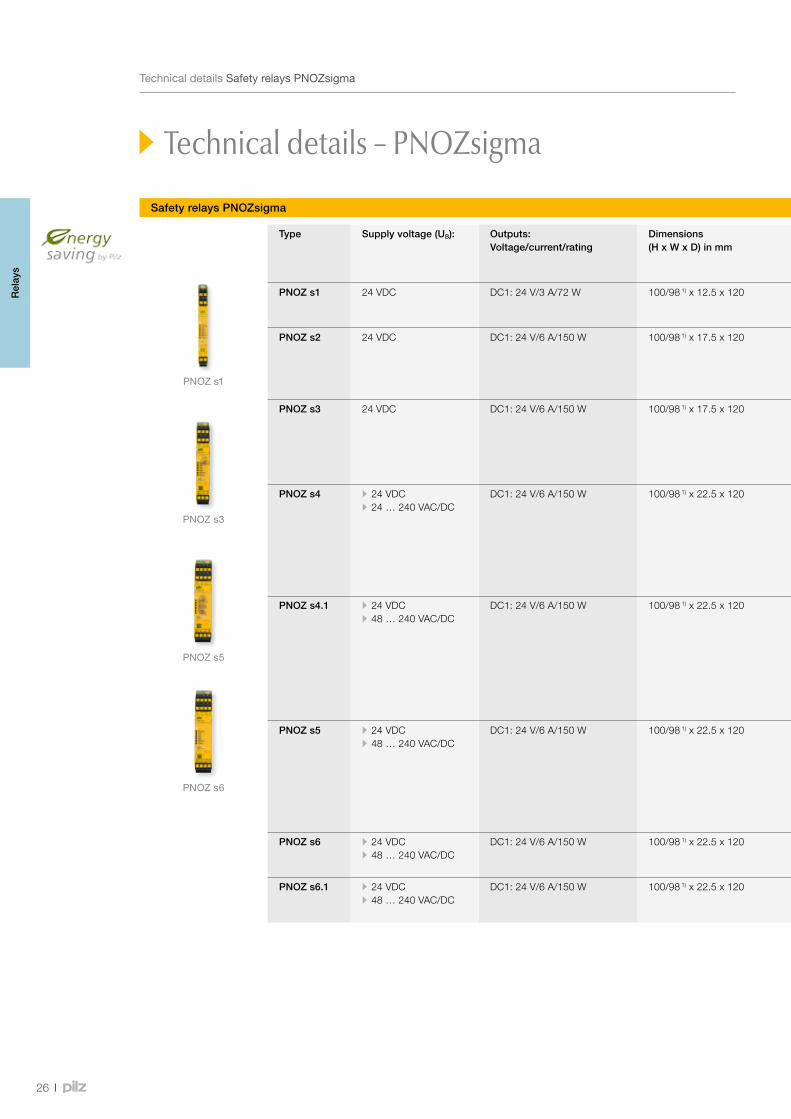
Safety relays PNOZsigma
Technical details – PNOZsigma
Type Supply voltage (UB): Outputs:Voltage/current/rating
Dimensions (H x W x D) in mm
Features Order number
Spring-loaded terminals Plug-in screw terminals
PNOZ s1 24 VDC DC1: 24 V/3 A/72 W 100/98 1) x 12.5 x 120 • Single-channel wiring • Manual/automatic reset
751 101 750 101
PNOZ s2 24 VDC DC1: 24 V/6 A/150 W 100/98 1) x 17.5 x 120 • Single-channel wiring • Monitored reset • Manual/automatic reset • Safe separation
751 102 750 102
PNOZ s3 24 VDC DC1: 24 V/6 A/150 W 100/98 1) x 17.5 x 120 • Single- and dual-channel wiring • Detection of shorts across contacts • Monitored reset • Manual/automatic reset • Start-up testing
751 103 750 103
PNOZ s4 • 24 VDC • 24 … 240 VAC/DC
DC1: 24 V/6 A/150 W 100/98 1) x 22.5 x 120 • Single- and dual-channel wiring • Detection of shorts across contacts • Monitored reset • Manual/automatic reset • Start-up testing • Approval to EN 81-1/A3 in accordance with the Lifts Directive
• 24 VDC 751 104 • 24 VDC, coated version 751 184 • 24 … 240 VAC/DC 751 134
• 24 VDC 750 104 • 24 … 240 VAC/DC 750 134
PNOZ s4.1 • 24 VDC • 48 … 240 VAC/DC
DC1: 24 V/6 A/150 W 100/98 1) x 22.5 x 120 • Single- and dual-channel wiring • Detection of shorts across contacts • Monitored reset • Manual/automatic reset • Start-up testing • 3 safe, diverse safety contacts • Approved in accordance with EN 50156-1 for electrical equipment for furnaces
• 24 VDC 751 124 • 48 … 240 VAC/DC 751 154
• 24 VDC 750 124 • 48 … 240 VAC/DC 750 154
PNOZ s5 • 24 VDC • 48 … 240 VAC/DC
DC1: 24 V/6 A/150 W 100/98 1) x 22.5 x 120 • Single- and dual-channel wiring • Detection of shorts across contacts • Monitored reset • Manual/automatic reset • Start-up testing • Timer functions: delay-on de-energisation • Time range: 0 … 300 s
• 24 VDC 751 105 • 24 VDC, coated version 751 185 • 48 … 240 VAC/DC 751 135
• 24 VDC 750 105 • 48 … 240 VAC/DC 750 135
PNOZ s6 • 24 VDC • 48 … 240 VAC/DC
DC1: 24 V/6 A/150 W 100/98 1) x 22.5 x 120 • Dual-channel wiring • Detection of shorts across contacts
• 24 VDC 751 106 • 48 … 240 VAC/DC 751 136
• 24 VDC 750 106 • 48 … 240 VAC/DC 750 136
PNOZ s6.1 • 24 VDC • 48 … 240 VAC/DC
DC1: 24 V/6 A/150 W 100/98 1) x 22.5 x 120 • Dual-channel wiring • Detection of shorts across contacts
• 24 VDC 751 126 • 48 … 240 VAC/DC 751 156
• 24 VDC 750 126 • 48 … 240 VAC/DC 750 156
1)Heightwithspring-loadedterminals/plug-inscrewterminals
Rel
ays
27
Webcode 0685
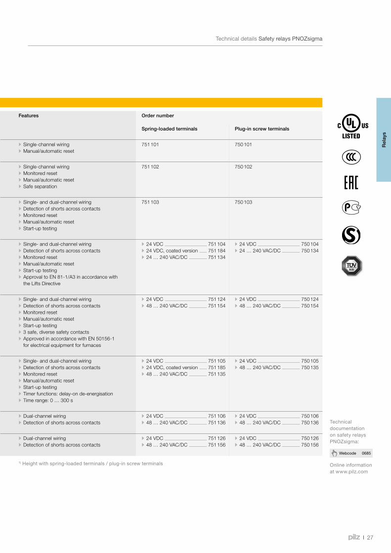
TechnicaldetailsSafetyrelaysPNOZsigma
Safety relays PNOZsigma
Onlineinformationatwww.pilz.com
TechnicaldocumentationonsafetyrelaysPNOZsigma:
Type Supply voltage (UB): Outputs:Voltage/current/rating
Dimensions (H x W x D) in mm
Features Order number
Spring-loaded terminals Plug-in screw terminals
PNOZ s1 24 VDC DC1: 24 V/3 A/72 W 100/98 1) x 12.5 x 120 • Single-channel wiring • Manual/automatic reset
751 101 750 101
PNOZ s2 24 VDC DC1: 24 V/6 A/150 W 100/98 1) x 17.5 x 120 • Single-channel wiring • Monitored reset • Manual/automatic reset • Safe separation
751 102 750 102
PNOZ s3 24 VDC DC1: 24 V/6 A/150 W 100/98 1) x 17.5 x 120 • Single- and dual-channel wiring • Detection of shorts across contacts • Monitored reset • Manual/automatic reset • Start-up testing
751 103 750 103
PNOZ s4 • 24 VDC • 24 … 240 VAC/DC
DC1: 24 V/6 A/150 W 100/98 1) x 22.5 x 120 • Single- and dual-channel wiring • Detection of shorts across contacts • Monitored reset • Manual/automatic reset • Start-up testing • Approval to EN 81-1/A3 in accordance with the Lifts Directive
• 24 VDC 751 104 • 24 VDC, coated version 751 184 • 24 … 240 VAC/DC 751 134
• 24 VDC 750 104 • 24 … 240 VAC/DC 750 134
PNOZ s4.1 • 24 VDC • 48 … 240 VAC/DC
DC1: 24 V/6 A/150 W 100/98 1) x 22.5 x 120 • Single- and dual-channel wiring • Detection of shorts across contacts • Monitored reset • Manual/automatic reset • Start-up testing • 3 safe, diverse safety contacts • Approved in accordance with EN 50156-1 for electrical equipment for furnaces
• 24 VDC 751 124 • 48 … 240 VAC/DC 751 154
• 24 VDC 750 124 • 48 … 240 VAC/DC 750 154
PNOZ s5 • 24 VDC • 48 … 240 VAC/DC
DC1: 24 V/6 A/150 W 100/98 1) x 22.5 x 120 • Single- and dual-channel wiring • Detection of shorts across contacts • Monitored reset • Manual/automatic reset • Start-up testing • Timer functions: delay-on de-energisation • Time range: 0 … 300 s
• 24 VDC 751 105 • 24 VDC, coated version 751 185 • 48 … 240 VAC/DC 751 135
• 24 VDC 750 105 • 48 … 240 VAC/DC 750 135
PNOZ s6 • 24 VDC • 48 … 240 VAC/DC
DC1: 24 V/6 A/150 W 100/98 1) x 22.5 x 120 • Dual-channel wiring • Detection of shorts across contacts
• 24 VDC 751 106 • 48 … 240 VAC/DC 751 136
• 24 VDC 750 106 • 48 … 240 VAC/DC 750 136
PNOZ s6.1 • 24 VDC • 48 … 240 VAC/DC
DC1: 24 V/6 A/150 W 100/98 1) x 22.5 x 120 • Dual-channel wiring • Detection of shorts across contacts
• 24 VDC 751 126 • 48 … 240 VAC/DC 751 156
• 24 VDC 750 126 • 48 … 240 VAC/DC 750 156
1)Heightwithspring-loadedterminals/plug-inscrewterminals
Rel
ays

PNOZ s8
PNOZ s10
PNOZ s30
PNOZ s7
28
Safety relays PNOZsigma
Technical details – PNOZsigma
Type Supply voltage (UB): Outputs:Voltage/current/rating
Dimensions (H x W x D) in mm
Features Order number
Spring-loaded terminals Plug-in screw terminals
PNOZ s7 24 VDC DC1: 24 V/6 A/150 W 100/98 1) x 17.5 x 120 • Safe separation • 24 VDC 751 107 • 24 VDC, coated version 751 187
750 107
PNOZ s7.1 24 VDC DC1: 24 V/6 A/150 W 100/98 1) x 17.5 x 120 • Cascading module for connection to PNOZ s7.2 • Safe separation of safety contacts • LEDs for input and switch status • Can also be used with other safety control devices, without a PNOZsigma base unit: one input circuit affects the output relays
751 167 750 167
PNOZ s7.2 24 VDC DC1: 24 V/6 A/150 W 100/98 1) x 17.5 x 120 • Contact expansion module in conjunction with PNOZ s7.1
751 177 750 177
PNOZ s8 24 VDC DC1: 24 V/3 A/72 W 100/98 1) x 12.5 x 120 - 751 108 750 108
PNOZ s9 24 VDC DC1: 24 V/6 A/150 W 100/98 1) x 17.5 x 120 • Safe separation • Timer functions: delay-on energisation, delay-on de-energisation, pulsing, retriggerable
• Time range: 0 … 300 s
• 24 VDC 751 109 • 24 VDC, coated version 751 189
750 109
PNOZ s10 24 VDC DC1: 24 V/12 A/300 W 100/98 1) x 45.0 x 120 • Safe separation 751 110 750 110
PNOZ s11 24 VDC DC1: 24 V/6 A/150 W 100/98 1) x 45.0 x 120 • Safe separation 751 111 750 111
PNOZ s22 24 VDC DC1: 24 V/6 A/150 W 100/98 1) x 22.5 x 120 • Two safety contacts that can be controlled separately
• Contact expansion for the speed monitor PNOZ s30 and the base units PNOZ mm0.1p/mm0.2p of the configurable safety relays PNOZmulti Mini
751 132 750 132
PNOZ s30 24 … 240 VAC/DC DC1: 24 V/4 A/100 W 100/98 1) x 45.0 x 120 • Safe monitoring of standstill, speed, direction of rotation and shear pin breakage
• Parameters for device functions can be freely set • Parameters are entered via rotary knob (push and turn) in conjunction with a monochrome display
• Set parameters are saved on a chip card • Integrated display shows the set limit values/parameters as well as the current speed
• Tolerances can be freely set for each limit value • Axis position monitoring is available as an option with the standstill function
• Advance warning of shutdown when a certain threshold is reached
751 330 750 330
1)Heightwithspring-loadedterminals/plug-inscrewterminals
TechnicaldetailsSafetyrelaysPNOZsigma
Rel
ays
29
Webcode 0685
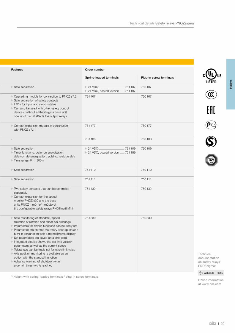
Safety relays PNOZsigma
Onlineinformationatwww.pilz.com
TechnicaldocumentationonsafetyrelaysPNOZsigma:
Type Supply voltage (UB): Outputs:Voltage/current/rating
Dimensions (H x W x D) in mm
Features Order number
Spring-loaded terminals Plug-in screw terminals
PNOZ s7 24 VDC DC1: 24 V/6 A/150 W 100/98 1) x 17.5 x 120 • Safe separation • 24 VDC 751 107 • 24 VDC, coated version 751 187
750 107
PNOZ s7.1 24 VDC DC1: 24 V/6 A/150 W 100/98 1) x 17.5 x 120 • Cascading module for connection to PNOZ s7.2 • Safe separation of safety contacts • LEDs for input and switch status • Can also be used with other safety control devices, without a PNOZsigma base unit: one input circuit affects the output relays
751 167 750 167
PNOZ s7.2 24 VDC DC1: 24 V/6 A/150 W 100/98 1) x 17.5 x 120 • Contact expansion module in conjunction with PNOZ s7.1
751 177 750 177
PNOZ s8 24 VDC DC1: 24 V/3 A/72 W 100/98 1) x 12.5 x 120 - 751 108 750 108
PNOZ s9 24 VDC DC1: 24 V/6 A/150 W 100/98 1) x 17.5 x 120 • Safe separation • Timer functions: delay-on energisation, delay-on de-energisation, pulsing, retriggerable
• Time range: 0 … 300 s
• 24 VDC 751 109 • 24 VDC, coated version 751 189
750 109
PNOZ s10 24 VDC DC1: 24 V/12 A/300 W 100/98 1) x 45.0 x 120 • Safe separation 751 110 750 110
PNOZ s11 24 VDC DC1: 24 V/6 A/150 W 100/98 1) x 45.0 x 120 • Safe separation 751 111 750 111
PNOZ s22 24 VDC DC1: 24 V/6 A/150 W 100/98 1) x 22.5 x 120 • Two safety contacts that can be controlled separately
• Contact expansion for the speed monitor PNOZ s30 and the base units PNOZ mm0.1p/mm0.2p of the configurable safety relays PNOZmulti Mini
751 132 750 132
PNOZ s30 24 … 240 VAC/DC DC1: 24 V/4 A/100 W 100/98 1) x 45.0 x 120 • Safe monitoring of standstill, speed, direction of rotation and shear pin breakage
• Parameters for device functions can be freely set • Parameters are entered via rotary knob (push and turn) in conjunction with a monochrome display
• Set parameters are saved on a chip card • Integrated display shows the set limit values/parameters as well as the current speed
• Tolerances can be freely set for each limit value • Axis position monitoring is available as an option with the standstill function
• Advance warning of shutdown when a certain threshold is reached
751 330 750 330
1)Heightwithspring-loadedterminals/plug-inscrewterminals
TechnicaldetailsSafetyrelaysPNOZsigma
Rel
ays
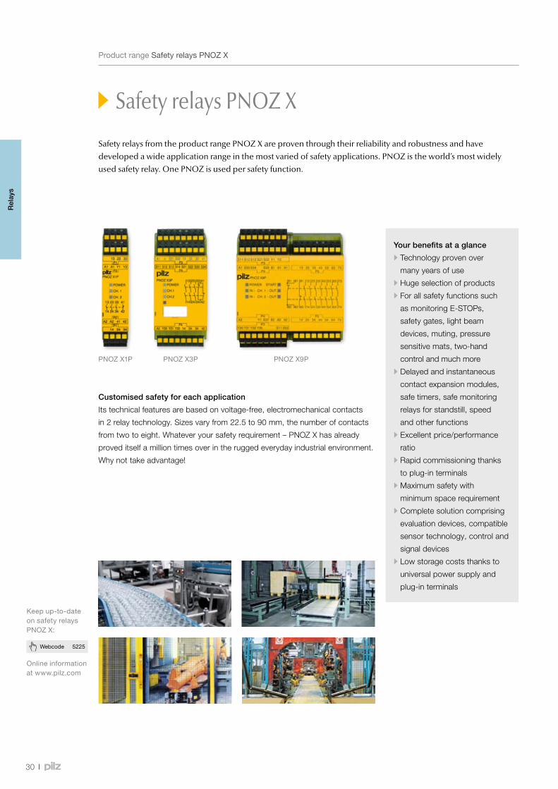
PNOZ X1P PNOZ X3P PNOZ X9P
30
Webcode 5225
ProductrangeSafetyrelaysPNOZ X
Safety relays PNOZ X
Customised safety for each application
Its technical features are based on voltage-free, electromechanical contacts
in 2 relay technology. Sizes vary from 22.5 to 90 mm, the number of contacts
from two to eight. Whatever your safety requirement – PNOZ X has already
proved itself a million times over in the rugged everyday industrial environment.
Why not take advantage!
Your benefits at a glance
•Technology proven over
many years of use
•Huge selection of products
•For all safety functions such
as monitoring E-STOPs,
safety gates, light beam
devices, muting, pressure
sensitive mats, two-hand
control and much more
•Delayed and instantaneous
contact expansion modules,
safe timers, safe monitoring
relays for standstill, speed
and other functions
•Excellent price/performance
ratio
•Rapid commissioning thanks
to plug-in terminals
•Maximum safety with
minimum space requirement
•Complete solution comprising
evaluation devices, compatible
sensor technology, control and
signal devices
•Low storage costs thanks to
universal power supply and
plug-in terminals
Onlineinformationatwww.pilz.com
Keepup-to-dateonsafetyrelaysPNOZ X:
Safety relays from the product range PNOZ X are proven through their reliability and robustness and have developed a wide application range in the most varied of safety applications. PNOZ is the world’s most widely used safety relay. One PNOZ is used per safety function.
Rel
ays
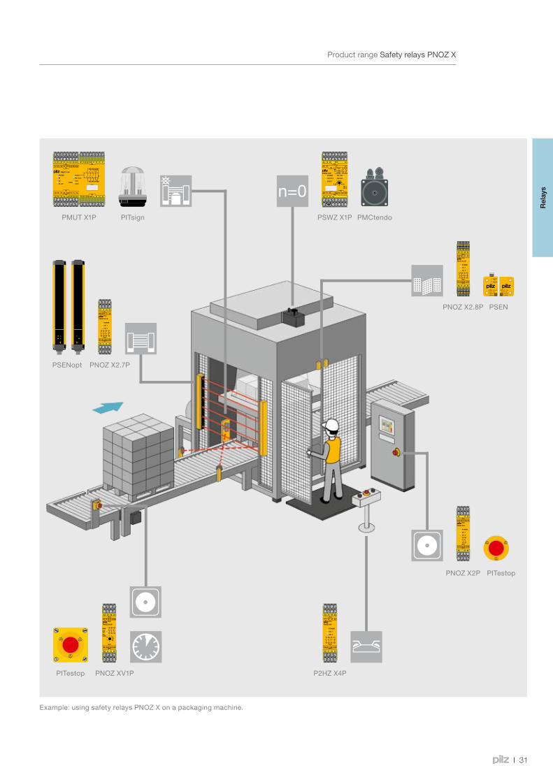
PSWZ X1PPMUT X1P PITsign
PNOZ X2.7PPSENopt
P2HZ X4P
PNOZ X2.8P
PNOZ XV1P
PNOZ X2P
PSEN
PITestop
PITestop
PMCtendo
31
Safety relays PNOZ X
ProductrangeSafetyrelaysPNOZ X
Example:usingsafetyrelaysPNOZ Xonapackagingmachine.
Rel
ays
32
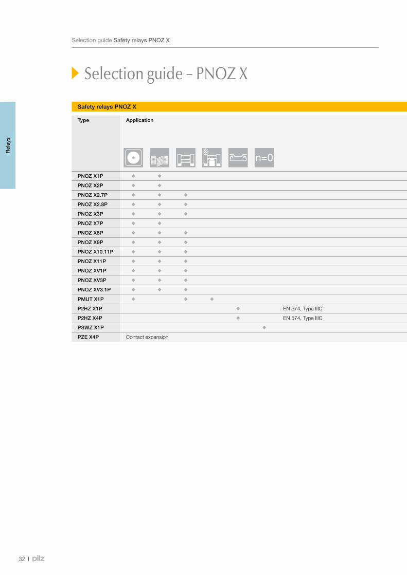
SelectionguideSafetyrelaysPNOZ X
Type Application Performance Level (PL) – EN ISO 13849-1
Safety Integrity Level (SIL) CL – claim limit in accordance with IEC 62061
Output contacts Housing width in mm
Safety-related Non-safety-related
PNOZ X1P e 3 3 - 1 - 22.5
PNOZ X2P e 3 2 - - - 22.5
PNOZ X2.7P e 3 3 - 1 - 22.5
PNOZ X2.8P e 3 3 - 1 - 22.5
PNOZ X3P e 3 3 - 1 1 45.0
PNOZ X7P e 3 2 - - - 22.5
PNOZ X8P e 3 3 - 2 2 45.0
PNOZ X9P e 3 7 - 2 2 90.0
PNOZ X10.11P e 3 6 - 4 - 90.0
PNOZ X11P e 3 7 - 1 2 90.0
PNOZ XV1P e (d) 1) 3 2 1 - - 22.5
PNOZ XV3P e (d) 1) 3 3 2 - - 45.0
PNOZ XV3.1P e (d) 1) 3 3 2 1 - 90.0
PMUT X1P e 3 3 - 1 5 90.0
P2HZ X1P EN 574, Type IIIC e 3 3 - 1 2 45.0
P2HZ X4P EN 574, Type IIIC e 3 3 - 1 - 22.5
PSWZ X1P e 3 2 - 1 1 45.0
PZE X4P Contact expansion e 3 4 - - - 22.5
1)Valueappliesforinstantaneous(delayed)safetycontacts
Selection guide – PNOZ X
Safety relays PNOZ X
Rel
ays

33
Webcode 0685
SelectionguideSafetyrelaysPNOZ X
Type Application Performance Level (PL) – EN ISO 13849-1
Safety Integrity Level (SIL) CL – claim limit in accordance with IEC 62061
Output contacts Housing width in mm
Safety-related Non-safety-related
PNOZ X1P e 3 3 - 1 - 22.5
PNOZ X2P e 3 2 - - - 22.5
PNOZ X2.7P e 3 3 - 1 - 22.5
PNOZ X2.8P e 3 3 - 1 - 22.5
PNOZ X3P e 3 3 - 1 1 45.0
PNOZ X7P e 3 2 - - - 22.5
PNOZ X8P e 3 3 - 2 2 45.0
PNOZ X9P e 3 7 - 2 2 90.0
PNOZ X10.11P e 3 6 - 4 - 90.0
PNOZ X11P e 3 7 - 1 2 90.0
PNOZ XV1P e (d) 1) 3 2 1 - - 22.5
PNOZ XV3P e (d) 1) 3 3 2 - - 45.0
PNOZ XV3.1P e (d) 1) 3 3 2 1 - 90.0
PMUT X1P e 3 3 - 1 5 90.0
P2HZ X1P EN 574, Type IIIC e 3 3 - 1 2 45.0
P2HZ X4P EN 574, Type IIIC e 3 3 - 1 - 22.5
PSWZ X1P e 3 2 - 1 1 45.0
PZE X4P Contact expansion e 3 4 - - - 22.5
1)Valueappliesforinstantaneous(delayed)safetycontacts
Onlineinformationatwww.pilz.com
TechnicaldocumentationonsafetyrelaysPNOZX:
Safety relays PNOZ X
Rel
ays
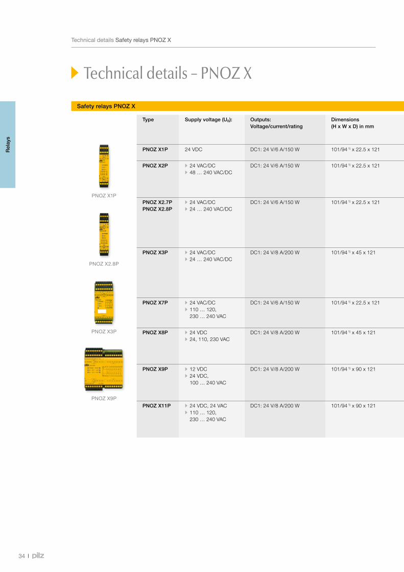
PNOZ X1P
PNOZ X3P
PNOZ X9P
PNOZ X2.8P
34
TechnicaldetailsSafetyrelaysPNOZ X
Safety relays PNOZ X
Technical details – PNOZ X
Type Supply voltage (UB): Outputs: Voltage/current/rating
Dimensions (H x W x D) in mm
Features Order number
Spring-loaded terminals Plug-in screw terminals
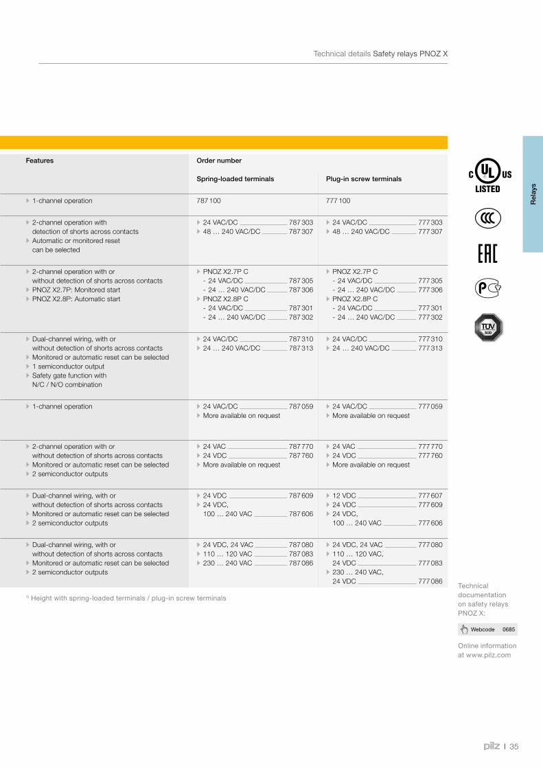
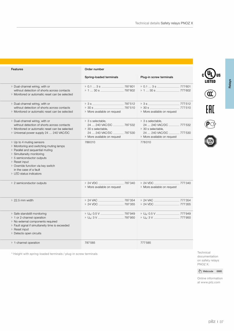
PNOZ X1P 24 VDC DC1: 24 V/6 A/150 W 101/94 1) x 22.5 x 121 • 1-channel operation 787 100 777 100
PNOZ X2P • 24 VAC/DC • 48 … 240 VAC/DC
DC1: 24 V/6 A/150 W 101/94 1) x 22.5 x 121 • 2-channel operation with detection of shorts across contacts
• Automatic or monitored reset can be selected
• 24 VAC/DC 787 303 • 48 … 240 VAC/DC 787 307
• 24 VAC/DC 777 303 • 48 … 240 VAC/DC 777 307
PNOZ X2.7PPNOZ X2.8P
• 24 VAC/DC • 24 … 240 VAC/DC
DC1: 24 V/6 A/150 W 101/94 1) x 22.5 x 121 • 2-channel operation with or without detection of shorts across contacts
• PNOZ X2.7P: Monitored start • PNOZ X2.8P: Automatic start
• PNOZ X2.7P C - 24 VAC/DC 787 305 - 24 … 240 VAC/DC 787 306
• PNOZ X2.8P C - 24 VAC/DC 787 301 - 24 … 240 VAC/DC 787 302
• PNOZ X2.7P C - 24 VAC/DC 777 305 - 24 … 240 VAC/DC 777 306
• PNOZ X2.8P C - 24 VAC/DC 777 301 - 24 … 240 VAC/DC 777 302
PNOZ X3P • 24 VAC/DC • 24 … 240 VAC/DC
DC1: 24 V/8 A/200 W 101/94 1) x 45 x 121 • Dual-channel wiring, with or without detection of shorts across contacts
• Monitored or automatic reset can be selected • 1 semiconductor output • Safety gate function with N/C / N/O combination
• 24 VAC/DC 787 310 • 24 … 240 VAC/DC 787 313
• 24 VAC/DC 777 310 • 24 … 240 VAC/DC 777 313
PNOZ X7P • 24 VAC/DC • 110 … 120, 230 … 240 VAC
DC1: 24 V/6 A/150 W 101/94 1) x 22.5 x 121 • 1-channel operation • 24 VAC/DC 787 059 • More available on request
• 24 VAC/DC 777 059 • More available on request
PNOZ X8P • 24 VDC • 24, 110, 230 VAC
DC1: 24 V/8 A/200 W 101/94 1) x 45 x 121 • 2-channel operation with or without detection of shorts across contacts
• Monitored or automatic reset can be selected • 2 semiconductor outputs
• 24 VAC 787 770 • 24 VDC 787 760 • More available on request
• 24 VAC 777 770 • 24 VDC 777 760 • More available on request
PNOZ X9P • 12 VDC • 24 VDC, 100 … 240 VAC
DC1: 24 V/8 A/200 W 101/94 1) x 90 x 121 • Dual-channel wiring, with or without detection of shorts across contacts
• Monitored or automatic reset can be selected • 2 semiconductor outputs
• 24 VDC 787 609 • 24 VDC, 100 … 240 VAC 787 606
• 12 VDC 777 607 • 24 VDC 777 609 • 24 VDC, 100 … 240 VAC 777 606
PNOZ X11P • 24 VDC, 24 VAC • 110 … 120, 230 … 240 VAC
DC1: 24 V/8 A/200 W 101/94 1) x 90 x 121 • Dual-channel wiring, with or without detection of shorts across contacts
• Monitored or automatic reset can be selected • 2 semiconductor outputs
• 24 VDC, 24 VAC 787 080 • 110 … 120 VAC 787 083 • 230 … 240 VAC 787 086
• 24 VDC, 24 VAC 777 080 • 110 … 120 VAC, 24 VDC 777 083
• 230 … 240 VAC, 24 VDC 777 086
1)Heightwithspring-loadedterminals/plug-inscrewterminals
Rel
ays
35
Webcode 0685
TechnicaldetailsSafetyrelaysPNOZ X
Safety relays PNOZ X
Type Supply voltage (UB): Outputs: Voltage/current/rating
Dimensions (H x W x D) in mm
Features Order number
Spring-loaded terminals Plug-in screw terminals
PNOZ X1P 24 VDC DC1: 24 V/6 A/150 W 101/94 1) x 22.5 x 121 • 1-channel operation 787 100 777 100
PNOZ X2P • 24 VAC/DC • 48 … 240 VAC/DC
DC1: 24 V/6 A/150 W 101/94 1) x 22.5 x 121 • 2-channel operation with detection of shorts across contacts
• Automatic or monitored reset can be selected
• 24 VAC/DC 787 303 • 48 … 240 VAC/DC 787 307
• 24 VAC/DC 777 303 • 48 … 240 VAC/DC 777 307
PNOZ X2.7PPNOZ X2.8P
• 24 VAC/DC • 24 … 240 VAC/DC
DC1: 24 V/6 A/150 W 101/94 1) x 22.5 x 121 • 2-channel operation with or without detection of shorts across contacts
• PNOZ X2.7P: Monitored start • PNOZ X2.8P: Automatic start
• PNOZ X2.7P C - 24 VAC/DC 787 305 - 24 … 240 VAC/DC 787 306
• PNOZ X2.8P C - 24 VAC/DC 787 301 - 24 … 240 VAC/DC 787 302
• PNOZ X2.7P C - 24 VAC/DC 777 305 - 24 … 240 VAC/DC 777 306
• PNOZ X2.8P C - 24 VAC/DC 777 301 - 24 … 240 VAC/DC 777 302
PNOZ X3P • 24 VAC/DC • 24 … 240 VAC/DC
DC1: 24 V/8 A/200 W 101/94 1) x 45 x 121 • Dual-channel wiring, with or without detection of shorts across contacts
• Monitored or automatic reset can be selected • 1 semiconductor output • Safety gate function with N/C / N/O combination
• 24 VAC/DC 787 310 • 24 … 240 VAC/DC 787 313
• 24 VAC/DC 777 310 • 24 … 240 VAC/DC 777 313
PNOZ X7P • 24 VAC/DC • 110 … 120, 230 … 240 VAC
DC1: 24 V/6 A/150 W 101/94 1) x 22.5 x 121 • 1-channel operation • 24 VAC/DC 787 059 • More available on request
• 24 VAC/DC 777 059 • More available on request
PNOZ X8P • 24 VDC • 24, 110, 230 VAC
DC1: 24 V/8 A/200 W 101/94 1) x 45 x 121 • 2-channel operation with or without detection of shorts across contacts
• Monitored or automatic reset can be selected • 2 semiconductor outputs
• 24 VAC 787 770 • 24 VDC 787 760 • More available on request
• 24 VAC 777 770 • 24 VDC 777 760 • More available on request
PNOZ X9P • 12 VDC • 24 VDC, 100 … 240 VAC
DC1: 24 V/8 A/200 W 101/94 1) x 90 x 121 • Dual-channel wiring, with or without detection of shorts across contacts
• Monitored or automatic reset can be selected • 2 semiconductor outputs
• 24 VDC 787 609 • 24 VDC, 100 … 240 VAC 787 606
• 12 VDC 777 607 • 24 VDC 777 609 • 24 VDC, 100 … 240 VAC 777 606
PNOZ X11P • 24 VDC, 24 VAC • 110 … 120, 230 … 240 VAC
DC1: 24 V/8 A/200 W 101/94 1) x 90 x 121 • Dual-channel wiring, with or without detection of shorts across contacts
• Monitored or automatic reset can be selected • 2 semiconductor outputs
• 24 VDC, 24 VAC 787 080 • 110 … 120 VAC 787 083 • 230 … 240 VAC 787 086
• 24 VDC, 24 VAC 777 080 • 110 … 120 VAC, 24 VDC 777 083
• 230 … 240 VAC, 24 VDC 777 086
1)Heightwithspring-loadedterminals/plug-inscrewterminals
Onlineinformationatwww.pilz.com
TechnicaldocumentationonsafetyrelaysPNOZX:
Rel
ays
PNOZ XV1P
PNOZ XV3P
PMUT X1P
P2HZX4P
36
TechnicaldetailsSafetyrelaysPNOZ X
Safety relays PNOZ X
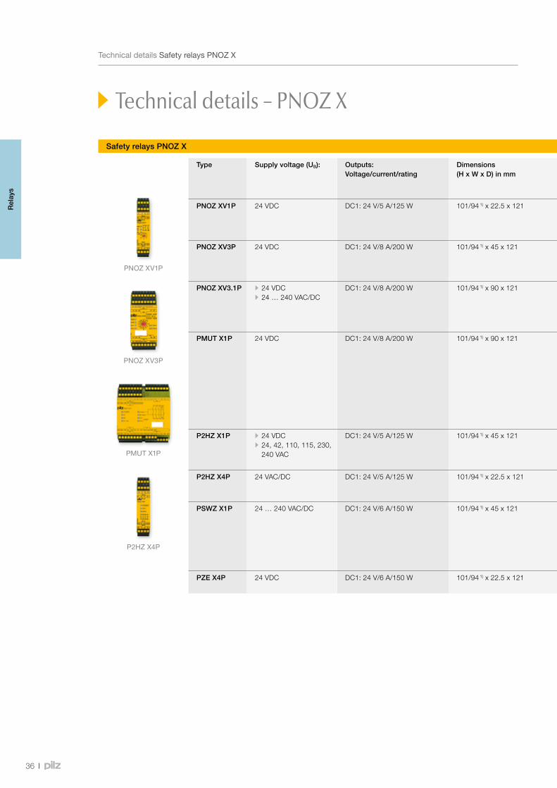
Technical details – PNOZ X
Type Supply voltage (UB): Outputs: Voltage/current/rating
Dimensions (H x W x D) in mm
Features Order number
Spring-loaded terminals Plug-in screw terminals
PNOZ XV1P 24 VDC DC1: 24 V/5 A/125 W 101/94 1) x 22.5 x 121 • Dual-channel wiring, with or without detection of shorts across contacts
• Monitored or automatic reset can be selected
• 0.1 … 3 s 787 601 • 1 … 30 s 787 602
• 0.1 … 3 s 777 601 • 1 … 30 s 777 602
PNOZ XV3P 24 VDC DC1: 24 V/8 A/200 W 101/94 1) x 45 x 121 • Dual-channel wiring, with or without detection of shorts across contacts
• Monitored or automatic reset can be selected
• 3 s 787 512 • 30 s 787 510 • More available on request
• 3 s 777 512 • 30 s 777 510 • More available on request
PNOZ XV3.1P • 24 VDC • 24 … 240 VAC/DC
DC1: 24 V/8 A/200 W 101/94 1) x 90 x 121 • Dual-channel wiring, with or without detection of shorts across contacts
• Monitored or automatic reset can be selected • Universal power supply 24 … 240 VAC/DC
• 3 s selectable, 24 … 240 VAC/DC 787 532
• 30 s selectable, 24 … 240 VAC/DC 787 530
• More available on request
• 3 s selectable, 24 … 240 VAC/DC 777 532
• 30 s selectable, 24 … 240 VAC/DC 777 530
• More available on request
PMUT X1P 24 VDC DC1: 24 V/8 A/200 W 101/94 1) x 90 x 121 • Up to 4 muting sensors • Monitoring and switching muting lamps • Parallel and sequential muting • Simultaneity monitoring • 5 semiconductor outputs • Reset input • Override function via key switch in the case of a fault
• LED status indicators
788 010 778 010
P2HZ X1P • 24 VDC • 24, 42, 110, 115, 230, 240 VAC
DC1: 24 V/5 A/125 W 101/94 1) x 45 x 121 • 2 semiconductor outputs • 24 VDC 787 340 • More available on request
• 24 VDC 777 340 • More available on request
P2HZ X4P 24 VAC/DC DC1: 24 V/5 A/125 W 101/94 1) x 22.5 x 121 • 22.5 mm width • 24 VAC 787 354 • 24 VDC 787 355
• 24 VAC 777 354 • 24 VDC 777 355
PSWZ X1P 24 … 240 VAC/DC DC1: 24 V/6 A/150 W 101/94 1) x 45 x 121 • Safe standstill monitoring • 1 or 2-channel operation • No external components required • Fault signal if simultaneity time is exceeded • Reset input • Detects open circuits
• UM: 0.5 V 787 949 • UM: 3 V 787 950
• UM: 0.5 V 777 949 • UM: 3 V 777 950
PZE X4P 24 VDC DC1: 24 V/6 A/150 W 101/94 1) x 22.5 x 121 • 1-channel operation 787 585 777 585
1)Heightwithspring-loadedterminals/plug-inscrewterminals
Rel
ays
37
Webcode 0685
TechnicaldetailsSafetyrelaysPNOZ X
Safety relays PNOZ X
Type Supply voltage (UB): Outputs: Voltage/current/rating
Dimensions (H x W x D) in mm
Features Order number
Spring-loaded terminals Plug-in screw terminals
PNOZ XV1P 24 VDC DC1: 24 V/5 A/125 W 101/94 1) x 22.5 x 121 • Dual-channel wiring, with or without detection of shorts across contacts
• Monitored or automatic reset can be selected
• 0.1 … 3 s 787 601 • 1 … 30 s 787 602
• 0.1 … 3 s 777 601 • 1 … 30 s 777 602
PNOZ XV3P 24 VDC DC1: 24 V/8 A/200 W 101/94 1) x 45 x 121 • Dual-channel wiring, with or without detection of shorts across contacts
• Monitored or automatic reset can be selected
• 3 s 787 512 • 30 s 787 510 • More available on request
• 3 s 777 512 • 30 s 777 510 • More available on request
PNOZ XV3.1P • 24 VDC • 24 … 240 VAC/DC
DC1: 24 V/8 A/200 W 101/94 1) x 90 x 121 • Dual-channel wiring, with or without detection of shorts across contacts
• Monitored or automatic reset can be selected • Universal power supply 24 … 240 VAC/DC
• 3 s selectable, 24 … 240 VAC/DC 787 532
• 30 s selectable, 24 … 240 VAC/DC 787 530
• More available on request
• 3 s selectable, 24 … 240 VAC/DC 777 532
• 30 s selectable, 24 … 240 VAC/DC 777 530
• More available on request
PMUT X1P 24 VDC DC1: 24 V/8 A/200 W 101/94 1) x 90 x 121 • Up to 4 muting sensors • Monitoring and switching muting lamps • Parallel and sequential muting • Simultaneity monitoring • 5 semiconductor outputs • Reset input • Override function via key switch in the case of a fault
• LED status indicators
788 010 778 010
P2HZ X1P • 24 VDC • 24, 42, 110, 115, 230, 240 VAC
DC1: 24 V/5 A/125 W 101/94 1) x 45 x 121 • 2 semiconductor outputs • 24 VDC 787 340 • More available on request
• 24 VDC 777 340 • More available on request
P2HZ X4P 24 VAC/DC DC1: 24 V/5 A/125 W 101/94 1) x 22.5 x 121 • 22.5 mm width • 24 VAC 787 354 • 24 VDC 787 355
• 24 VAC 777 354 • 24 VDC 777 355
PSWZ X1P 24 … 240 VAC/DC DC1: 24 V/6 A/150 W 101/94 1) x 45 x 121 • Safe standstill monitoring • 1 or 2-channel operation • No external components required • Fault signal if simultaneity time is exceeded • Reset input • Detects open circuits
• UM: 0.5 V 787 949 • UM: 3 V 787 950
• UM: 0.5 V 777 949 • UM: 3 V 777 950
PZE X4P 24 VDC DC1: 24 V/6 A/150 W 101/94 1) x 22.5 x 121 • 1-channel operation 787 585 777 585
1)Heightwithspring-loadedterminals/plug-inscrewterminals
Onlineinformationatwww.pilz.com
TechnicaldocumentationonsafetyrelaysPNOZX:
Rel
ays
PNOZ c1 PNOZ c2
38
ProductrangeSafetyrelaysPNOZcompact
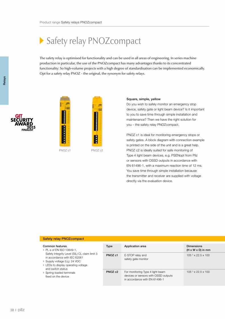
Safety relay PNOZcompact
Square, simple, yellow
Do you wish to safely monitor an emergency stop
device, safety gate or light beam device? Is it important
to you to save time through simple installation and
maintenance? Then we have the right solution for
you – the safety relay PNOZcompact.
PNOZ c1 is ideal for monitoring emergency stops or
safety gates. A block diagram with connection example
is printed on the side of the unit and is a great help.
PNOZ c2 is ideally suited for safe monitoring of
Type 4 light beam devices, e.g. PSENopt from Pilz
or sensors with OSSD outputs in accordance with
EN 61496-1, with a maximum reaction time of 12 ms.
You save time through simple installation because
the transmitter and receiver are supplied with voltage
directly via the evaluation device.
The safety relay is optimised for functionality and can be used in all areas of engineering. In series machine production in particular, the use of the PNOZcompact has many advantages thanks to its concentrated functionality: So high-volume projects with a high degree of standardisation can be implemented economically. Opt for a safety relay PNOZ – the original, the synonym for safety relays.
Rel
ays
Common features • PL e of EN ISO 13849-1, Safety Integrity Level (SIL) CL claim limit 3 in accordance with IEC 62061
• Supply voltage (UB): 24 VDC • LEDs to display operating voltage and switch status
• Spring-loaded terminals fixed on the device
Safety relay PNOZcompact
Type Application area Dimensions (H x W x D) in mm
Features Order number
PNOZ c1 E-STOP relay and safety gate monitor
105 1) x 22.5 x 100 • 3 safety contacts/1 auxiliary contact (3 N/O/1 N/C) • Dual-channel wiring with detection of shorts across contacts, manual or automatic reset • Stop category: 0
710 001
PNOZ c2 For monitoring Type 4 light beam devices or sensors with OSSD outputs in accordance with EN 61496-1
105 1) x 22.5 x 100 • 2 safety contacts (N/O)/1 semiconductor output • Dual-channel wiring without detection of shorts across contacts, monitored or automatic start
710 002
1)Heightincl.springclip

PSENoptPNOZ c2
39
Webcode 8180
Safety relay PNOZcompact
TechnicaldetailsSafetyrelaysPNOZcompact
Your benefits at a glance
•Save space in the control
cabinet thanks to the
compact design
•Save time through simple
installation and maintenance:
push-in spring terminals fixed
on the device, connected
without the need for tools
•Tool-free assembly: simply attach
the device to the top hat rail
Onlineinformationatwww.pilz.com
Keepup-to-dateonsafetyrelaysPNOZcompact:
MonitoranE-STOPorsafetygate–inanyapplication–inanyapplication–safe,simple,compact.Useonesafetyrelaypersafetyfunction.
MonitorlightbeamdevicessuchasPSENoptfromPilzorsensorswithOSSDoutputsinsafe,simpleandcompactform.Allcommonlightbeamdevicescanalsobeconnected.
Rel
ays
Safety relay PNOZcompact
Type Application area Dimensions (H x W x D) in mm
Features Order number
PNOZ c1 E-STOP relay and safety gate monitor
105 1) x 22.5 x 100 • 3 safety contacts/1 auxiliary contact (3 N/O/1 N/C) • Dual-channel wiring with detection of shorts across contacts, manual or automatic reset • Stop category: 0
710 001
PNOZ c2 For monitoring Type 4 light beam devices or sensors with OSSD outputs in accordance with EN 61496-1
105 1) x 22.5 x 100 • 2 safety contacts (N/O)/1 semiconductor output • Dual-channel wiring without detection of shorts across contacts, monitored or automatic start
710 002
1)Heightincl.springclip
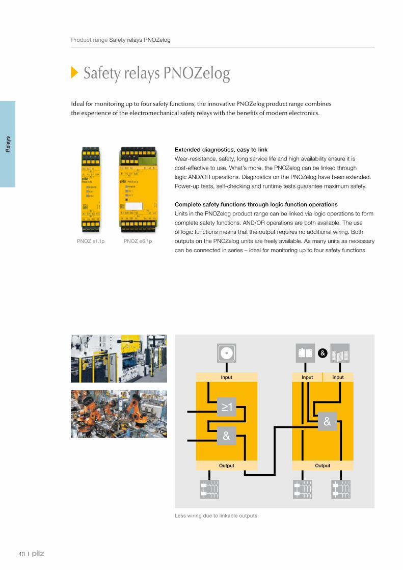
PNOZ e1.1p PNOZ e6.1p
&
40
ProductrangeSafetyrelaysPNOZelog
Safety relays PNOZelog
Extended diagnostics, easy to link
Wear-resistance, safety, long service life and high availability ensure it is
cost-effective to use. What’s more, the PNOZelog can be linked through
logic AND/OR operations. Diagnostics on the PNOZelog have been extended.
Power-up tests, self-checking and runtime tests guarantee maximum safety.
Complete safety functions through logic function operations
Units in the PNOZelog product range can be linked via logic operations to form
complete safety functions. AND/OR operations are both available. The use
of logic functions means that the output requires no additional wiring. Both
outputs on the PNOZelog units are freely available. As many units as necessary
can be connected in series – ideal for monitoring up to four safety functions.
Lesswiringduetolinkableoutputs.
Input
Output
Input
Output
Input
Ideal for monitoring up to four safety functions, the innovative PNOZelog product range combines the experience of the electromechanical safety relays with the benefits of modern electronics.
Rel
ays
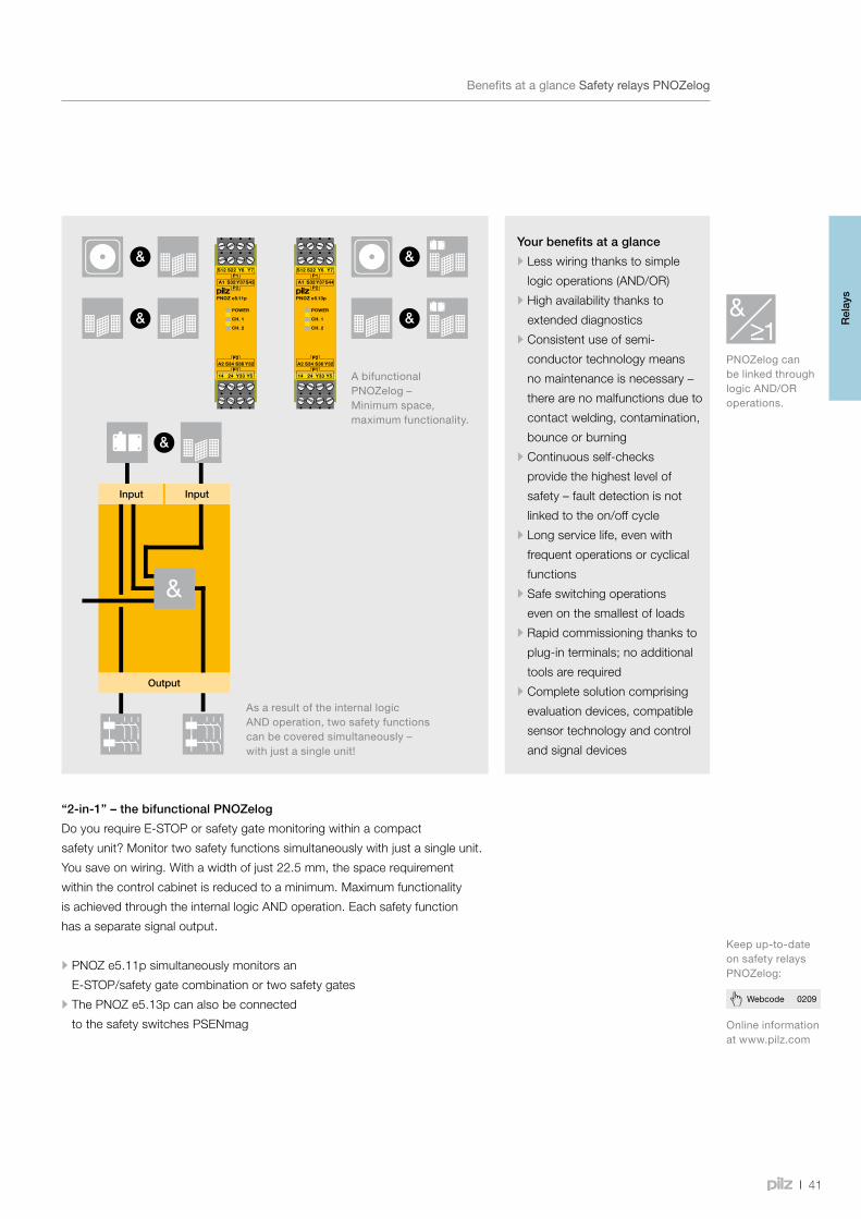
&
&
&
&
&
41
Webcode 0209
Safety relays PNOZelog
BenefitsataglanceSafetyrelaysPNOZelog
Your benefits at a glance
•Less wiring thanks to simple
logic operations (AND/OR)
•High availability thanks to
extended diagnostics
•Consistent use of semi-
conductor technology means
no maintenance is necessary –
there are no malfunctions due to
contact welding, contamination,
bounce or burning
•Continuous self-checks
provide the highest level of
safety – fault detection is not
linked to the on/off cycle
•Long service life, even with
frequent operations or cyclical
functions
•Safe switching operations
even on the smallest of loads
•Rapid commissioning thanks to
plug-in terminals; no additional
tools are required
•Complete solution comprising
evaluation devices, compatible
sensor technology and control
and signal devices
Onlineinformationatwww.pilz.com
Keepup-to-dateonsafetyrelaysPNOZelog:
PNOZelogcanbelinkedthroughlogicAND/ORoperations.
“2-in-1” – the bifunctional PNOZelog
Do you require E-STOP or safety gate monitoring within a compact
safety unit? Monitor two safety functions simultaneously with just a single unit.
You save on wiring. With a width of just 22.5 mm, the space requirement
within the control cabinet is reduced to a minimum. Maximum functionality
is achieved through the internal logic AND operation. Each safety function
has a separate signal output.
•PNOZ e5.11p simultaneously monitors an
E-STOP/safety gate combination or two safety gates
•The PNOZ e5.13p can also be connected
to the safety switches PSENmag
AsaresultoftheinternallogicANDoperation,twosafetyfunctionscanbecoveredsimultaneously–withjustasingleunit!
AbifunctionalPNOZelog–Minimumspace,maximumfunctionality.
Input
Output
Input
Rel
ays
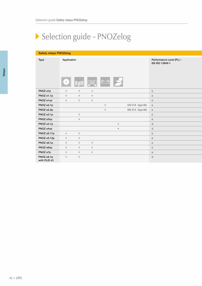
42
SelectionguideSafetyrelaysPNOZelog
Safety relays PNOZelog
Type Application Performance Level (PL) – EN ISO 13849-1
Safety Integrity Level (SIL) CL – claim limit in accordance with IEC 62061
Semiconductor outputs Relay outputs Link
Safety-related Non-safety-related
Safety-related
PNOZ e1p e 3 2 1 - -
PNOZ e1.1p e 3 2 1 - -
PNOZ e1vp e 3 2 1 - -
PNOZ e2.1p EN 574, Type IIIC e 3 2 1 - -
PNOZ e2.2p EN 574, Type IIIA e 1 2 1 - -
PNOZ e3.1p e 3 2 1 - -
PNOZ e3vp e 3 2 1 - -
PNOZ e4.1p d 2 2 1 - -
PNOZ e4vp d 2 2 1 - -
PNOZ e5.11p e 3 2 2 - - 1)
PNOZ e5.13p e 3 2 2 - - 1)
PNOZ e6.1p e 3 2 1 4 -
PNOZ e6vp e 3 2 1 4 -
PNOZ e7p e 3 2 1 - -
PNOZ e8.1p with PLID d1
d 2 2 2 - -
1)AlsoAND-linkedinternally
Selection guide – PNOZelog
Rel
ays
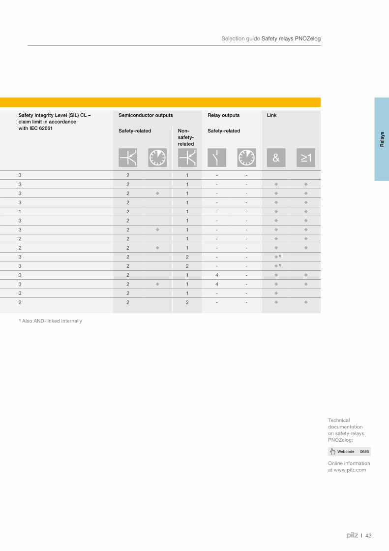
43
Webcode 0685
SelectionguideSafetyrelaysPNOZelog
Safety relays PNOZelog
Type Application Performance Level (PL) – EN ISO 13849-1
Safety Integrity Level (SIL) CL – claim limit in accordance with IEC 62061
Semiconductor outputs Relay outputs Link
Safety-related Non-safety-related
Safety-related
PNOZ e1p e 3 2 1 - -
PNOZ e1.1p e 3 2 1 - -
PNOZ e1vp e 3 2 1 - -
PNOZ e2.1p EN 574, Type IIIC e 3 2 1 - -
PNOZ e2.2p EN 574, Type IIIA e 1 2 1 - -
PNOZ e3.1p e 3 2 1 - -
PNOZ e3vp e 3 2 1 - -
PNOZ e4.1p d 2 2 1 - -
PNOZ e4vp d 2 2 1 - -
PNOZ e5.11p e 3 2 2 - - 1)
PNOZ e5.13p e 3 2 2 - - 1)
PNOZ e6.1p e 3 2 1 4 -
PNOZ e6vp e 3 2 1 4 -
PNOZ e7p e 3 2 1 - -
PNOZ e8.1p with PLID d1
d 2 2 2 - -
1)AlsoAND-linkedinternally
Onlineinformationatwww.pilz.com
TechnicaldocumentationonsafetyrelaysPNOZelog:
Rel
ays
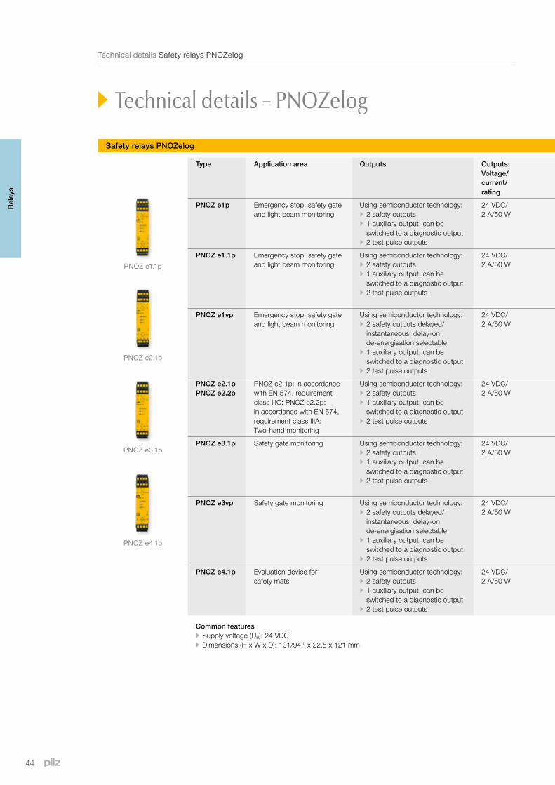
PNOZ e1.1p
PNOZ e2.1p
PNOZ e3.1p
PNOZ e4.1p
44
TechnicaldetailsSafetyrelaysPNOZelog
Safety relays PNOZelog
Technical details – PNOZelog
Type Application area Outputs Outputs:Voltage/ current/ rating
Features Order number
Spring-loaded terminals Plug-in screw terminals
PNOZ e1p Emergency stop, safety gate and light beam monitoring
Using semiconductor technology: • 2 safety outputs • 1 auxiliary output, can be switched to a diagnostic output
• 2 test pulse outputs
24 VDC/ 2 A/50 W
• Evaluation device for non-contact, coded safety switches PSENcode
• Monitored or automatic reset can be selected • Selectable monitoring of shorts across contacts
784 130 774 130
PNOZ e1.1p Emergency stop, safety gate and light beam monitoring
Using semiconductor technology: • 2 safety outputs • 1 auxiliary output, can be switched to a diagnostic output
• 2 test pulse outputs
24 VDC/2 A/50 W
• Evaluation device for non-contact, coded safety switches PSENcode
• Monitored or automatic reset can be selected • One AND and one OR input for logic AND/OR connections between several PNOZelog units
• Selectable monitoring of shorts across contacts
784 133 774 133
PNOZ e1vp Emergency stop, safety gate and light beam monitoring
Using semiconductor technology: • 2 safety outputs delayed/ instantaneous, delay-on de-energisation selectable
• 1 auxiliary output, can be switched to a diagnostic output
• 2 test pulse outputs
24 VDC/2 A/50 W
• Evaluation device for non-contact, coded safety switches PSENcode
• Monitored or automatic reset can be selected • One AND and one OR input for logic AND/OR connections between several PNOZelog units
• Selectable monitoring of shorts across contacts
• 10 s 784 131 • 300 s 784 132
• 10 s 774 131 • 300 s 774 132
PNOZ e2.1pPNOZ e2.2p
PNOZ e2.1p: in accordance with EN 574, requirement class IIIC; PNOZ e2.2p: in accordance with EN 574, requirement class IIIA: Two-hand monitoring
Using semiconductor technology: • 2 safety outputs • 1 auxiliary output, can be switched to a diagnostic output
• 2 test pulse outputs
24 VDC/2 A/50 W
• One AND and one OR input for logic AND/OR connections between several PNOZelog units
• Shorts across contacts are monitored via two test pulse outputs • Status display • Feedback loop for monitoring external contactors
• PNOZ e2.1p 784 136 • PNOZ e2.2p 784 135
• PNOZ e2.1p 774 136 • PNOZ e2.2p 774 135
PNOZ e3.1p Safety gate monitoring Using semiconductor technology: • 2 safety outputs • 1 auxiliary output, can be switched to a diagnostic output
• 2 test pulse outputs
24 VDC/2 A/50 W
• Evaluation device for position switches and for non-contact, magnetic safety switches PSENmag (Series 2)
• Monitored or automatic reset can be selected • One AND and one OR input for logic AND/OR connections between several PNOZelog units
• Selectable monitoring of shorts across contacts
784 139 774 139
PNOZ e3vp Safety gate monitoring Using semiconductor technology: • 2 safety outputs delayed/ instantaneous, delay-on de-energisation selectable
• 1 auxiliary output, can be switched to a diagnostic output
• 2 test pulse outputs
24 VDC/2 A/50 W
• Evaluation device for position switches and for non-contact, magnetic safety switches PSENmag (Series 2)
• Monitored or automatic reset can be selected • One AND and one OR input for logic AND/OR connections between several PNOZelog units
• Selectable monitoring of shorts across contacts
• 10 s 784 137 • 300 s 784 138
• 10 s 774 137 • 300 s 774 138
PNOZ e4.1p Evaluation device for safety mats
Using semiconductor technology: • 2 safety outputs • 1 auxiliary output, can be switched to a diagnostic output
• 2 test pulse outputs
24 VDC/2 A/50 W
• Used to connect Mayser safety mats, type: SM/BK • Suitable for controlling PSS/SafetyBUS p/PNOZmulti • One AND and one OR input for logic AND/OR connections between several PNOZelog units
• With or without reset function
784 180 774 180
Common features • Supply voltage (UB): 24 VDC • Dimensions (H x W x D): 101/94 1) x 22.5 x 121 mm
1)Heightwithspring-loadedterminals/plug-inscrewterminals
Rel
ays
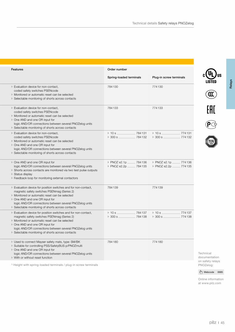
45
Webcode 0685
TechnicaldetailsSafetyrelaysPNOZelog
Safety relays PNOZelog
Type Application area Outputs Outputs:Voltage/ current/ rating
Features Order number
Spring-loaded terminals Plug-in screw terminals
PNOZ e1p Emergency stop, safety gate and light beam monitoring
Using semiconductor technology: • 2 safety outputs • 1 auxiliary output, can be switched to a diagnostic output
• 2 test pulse outputs
24 VDC/ 2 A/50 W
• Evaluation device for non-contact, coded safety switches PSENcode
• Monitored or automatic reset can be selected • Selectable monitoring of shorts across contacts
784 130 774 130
PNOZ e1.1p Emergency stop, safety gate and light beam monitoring
Using semiconductor technology: • 2 safety outputs • 1 auxiliary output, can be switched to a diagnostic output
• 2 test pulse outputs
24 VDC/2 A/50 W
• Evaluation device for non-contact, coded safety switches PSENcode
• Monitored or automatic reset can be selected • One AND and one OR input for logic AND/OR connections between several PNOZelog units
• Selectable monitoring of shorts across contacts
784 133 774 133
PNOZ e1vp Emergency stop, safety gate and light beam monitoring
Using semiconductor technology: • 2 safety outputs delayed/ instantaneous, delay-on de-energisation selectable
• 1 auxiliary output, can be switched to a diagnostic output
• 2 test pulse outputs
24 VDC/2 A/50 W
• Evaluation device for non-contact, coded safety switches PSENcode
• Monitored or automatic reset can be selected • One AND and one OR input for logic AND/OR connections between several PNOZelog units
• Selectable monitoring of shorts across contacts
• 10 s 784 131 • 300 s 784 132
• 10 s 774 131 • 300 s 774 132
PNOZ e2.1pPNOZ e2.2p
PNOZ e2.1p: in accordance with EN 574, requirement class IIIC; PNOZ e2.2p: in accordance with EN 574, requirement class IIIA: Two-hand monitoring
Using semiconductor technology: • 2 safety outputs • 1 auxiliary output, can be switched to a diagnostic output
• 2 test pulse outputs
24 VDC/2 A/50 W
• One AND and one OR input for logic AND/OR connections between several PNOZelog units
• Shorts across contacts are monitored via two test pulse outputs • Status display • Feedback loop for monitoring external contactors
• PNOZ e2.1p 784 136 • PNOZ e2.2p 784 135
• PNOZ e2.1p 774 136 • PNOZ e2.2p 774 135
PNOZ e3.1p Safety gate monitoring Using semiconductor technology: • 2 safety outputs • 1 auxiliary output, can be switched to a diagnostic output
• 2 test pulse outputs
24 VDC/2 A/50 W
• Evaluation device for position switches and for non-contact, magnetic safety switches PSENmag (Series 2)
• Monitored or automatic reset can be selected • One AND and one OR input for logic AND/OR connections between several PNOZelog units
• Selectable monitoring of shorts across contacts
784 139 774 139
PNOZ e3vp Safety gate monitoring Using semiconductor technology: • 2 safety outputs delayed/ instantaneous, delay-on de-energisation selectable
• 1 auxiliary output, can be switched to a diagnostic output
• 2 test pulse outputs
24 VDC/2 A/50 W
• Evaluation device for position switches and for non-contact, magnetic safety switches PSENmag (Series 2)
• Monitored or automatic reset can be selected • One AND and one OR input for logic AND/OR connections between several PNOZelog units
• Selectable monitoring of shorts across contacts
• 10 s 784 137 • 300 s 784 138
• 10 s 774 137 • 300 s 774 138
PNOZ e4.1p Evaluation device for safety mats
Using semiconductor technology: • 2 safety outputs • 1 auxiliary output, can be switched to a diagnostic output
• 2 test pulse outputs
24 VDC/2 A/50 W
• Used to connect Mayser safety mats, type: SM/BK • Suitable for controlling PSS/SafetyBUS p/PNOZmulti • One AND and one OR input for logic AND/OR connections between several PNOZelog units
• With or without reset function
784 180 774 180
Common features • Supply voltage (UB): 24 VDC • Dimensions (H x W x D): 101/94 1) x 22.5 x 121 mm
1)Heightwithspring-loadedterminals/plug-inscrewterminals
Onlineinformationatwww.pilz.com
TechnicaldocumentationonsafetyrelaysPNOZelog:
Rel
ays
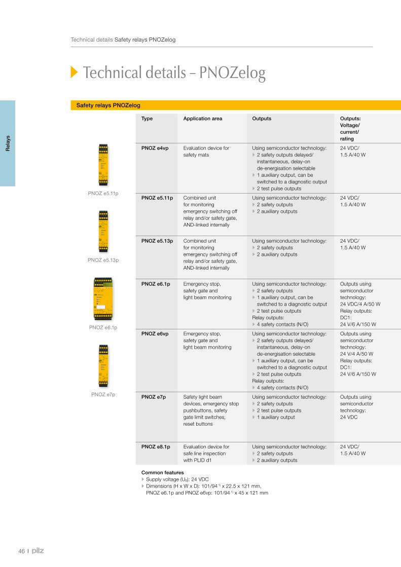
PNOZ e5.11p
PNOZ e6.1p
PNOZ e7p
PNOZ e5.13p
46
TechnicaldetailsSafetyrelaysPNOZelog
Safety relays PNOZelog
Technical details – PNOZelog
Type Application area Outputs Outputs: Voltage/ current/ rating
Features Order number
Spring-loaded terminals Plug-in screw terminals
PNOZ e4vp Evaluation device for safety mats
Using semiconductor technology: • 2 safety outputs delayed/ instantaneous, delay-on de-energisation selectable
• 1 auxiliary output, can be switched to a diagnostic output
• 2 test pulse outputs
24 VDC/1.5 A/40 W
• Used to connect Mayser safety mats, type: SM/BK • Suitable for controlling PSS/PNOZmulti • One AND and one OR input for logic AND/OR connections between several PNOZelog units
• With or without reset function
10 s 784181 • 10 s 774 181 • 300 s 774 182
PNOZ e5.11p Combined unit for monitoring emergency switching off relay and/or safety gate, AND-linked internally
Using semiconductor technology: • 2 safety outputs • 2 auxiliary outputs
24 VDC/1.5 A/40 W
• 2 safety functions in one unit, AND-linked internally • Evaluation device for position switches and non-contact, coded safety switches PSENcode
• One AND input for logic AND operations between several PNOZelog units
• Monitored or automatic reset can be selected
784 190 774 190
PNOZ e5.13p Combined unit for monitoring emergency switching off relay and/or safety gate, AND-linked internally
Using semiconductor technology: • 2 safety outputs • 2 auxiliary outputs
24 VDC/1.5 A/40 W
• 2 safety functions in one unit, AND-linked internally • Evaluation device for position switches, non-contact safety switches PSENcode and PSENmag (Series 2.X)
• Monitored or automatic reset can be selected • One AND input for logic AND operations between several PNOZelog units
784 191 774 191
PNOZ e6.1p Emergency stop, safety gate and light beam monitoring
Using semiconductor technology: • 2 safety outputs • 1 auxiliary output, can be switched to a diagnostic output
• 2 test pulse outputsRelay outputs: • 4 safety contacts (N/O)
Outputs using semiconductor technology: 24 VDC/4 A/50 WRelay outputs:DC1: 24 V/6 A/150 W
• Connection option for E-STOP pushbuttons, safety gate limit switches, reset buttons, safety mats and safe edges made by Haake, proximity switch evaluation devices
• Monitored or automatic reset can be selected • One AND and one OR input for logic AND/OR connections between several PNOZelog units
• Selectable monitoring of shorts across contacts
784 192 774 192
PNOZ e6vp Emergency stop, safety gate and light beam monitoring
Using semiconductor technology: • 2 safety outputs delayed/ instantaneous, delay-on de-energisation selectable
• 1 auxiliary output, can be switched to a diagnostic output
• 2 test pulse outputsRelay outputs: • 4 safety contacts (N/O)
Outputs using semiconductor technology: 24 V/4 A/50 WRelay outputs:DC1: 24 V/6 A/150 W
• Connection option for E-STOP pushbuttons, safety gate limit switches, reset buttons, safety mats and safe edges made by Haake, proximity switch evaluation devices
• Monitored or automatic reset can be selected • One AND and one OR input for logic AND/OR connections between several PNOZelog units
• Selectable monitoring of shorts across contacts
784 193 774 193
PNOZ e7p Safety light beam devices, emergency stop pushbuttons, safety gate limit switches, reset buttons
Using semiconductor technology: • 2 safety outputs • 2 test pulse outputs • 1 auxiliary output
Outputs using semiconductor technology: 24 VDC
• Connection option for E-STOP pushbuttons, safety gate limit switches, reset buttons, safety mats and safe edges made by Haake, proximity switch evaluation devices
• Monitored or automatic reset can be selected • One AND and one OR input for logic AND/OR connections between several PNOZelog units
• Selectable monitoring of shorts across contacts
784 197 774 197
PNOZ e8.1p Evaluation device for safe line inspection with PLID d1
Using semiconductor technology: • 2 safety outputs • 2 auxiliary outputs
24 VDC/1.5 A/40 W
• Monitored or automatic reset can be selected • Monitoring of shorts across contacts can be selected for E-STOP application
784 198 774 198
Common features • Supply voltage (UB): 24 VDC • Dimensions (H x W x D): 101/94 1) x 22.5 x 121 mm, PNOZ e6.1p and PNOZ e6vp: 101/94 1) x 45 x 121 mm
1)Heightwithspring-loadedterminals/plug-inscrewterminals
Rel
ays

47
Webcode 0685
TechnicaldetailsSafetyrelaysPNOZelog
Safety relays PNOZelog
Type Application area Outputs Outputs: Voltage/ current/ rating
Features Order number
Spring-loaded terminals Plug-in screw terminals
PNOZ e4vp Evaluation device for safety mats
Using semiconductor technology: • 2 safety outputs delayed/ instantaneous, delay-on de-energisation selectable
• 1 auxiliary output, can be switched to a diagnostic output
• 2 test pulse outputs
24 VDC/1.5 A/40 W
• Used to connect Mayser safety mats, type: SM/BK • Suitable for controlling PSS/PNOZmulti • One AND and one OR input for logic AND/OR connections between several PNOZelog units
• With or without reset function
10 s 784181 • 10 s 774 181 • 300 s 774 182
PNOZ e5.11p Combined unit for monitoring emergency switching off relay and/or safety gate, AND-linked internally
Using semiconductor technology: • 2 safety outputs • 2 auxiliary outputs
24 VDC/1.5 A/40 W
• 2 safety functions in one unit, AND-linked internally • Evaluation device for position switches and non-contact, coded safety switches PSENcode
• One AND input for logic AND operations between several PNOZelog units
• Monitored or automatic reset can be selected
784 190 774 190
PNOZ e5.13p Combined unit for monitoring emergency switching off relay and/or safety gate, AND-linked internally
Using semiconductor technology: • 2 safety outputs • 2 auxiliary outputs
24 VDC/1.5 A/40 W
• 2 safety functions in one unit, AND-linked internally • Evaluation device for position switches, non-contact safety switches PSENcode and PSENmag (Series 2.X)
• Monitored or automatic reset can be selected • One AND input for logic AND operations between several PNOZelog units
784 191 774 191
PNOZ e6.1p Emergency stop, safety gate and light beam monitoring
Using semiconductor technology: • 2 safety outputs • 1 auxiliary output, can be switched to a diagnostic output
• 2 test pulse outputsRelay outputs: • 4 safety contacts (N/O)
Outputs using semiconductor technology: 24 VDC/4 A/50 WRelay outputs:DC1: 24 V/6 A/150 W
• Connection option for E-STOP pushbuttons, safety gate limit switches, reset buttons, safety mats and safe edges made by Haake, proximity switch evaluation devices
• Monitored or automatic reset can be selected • One AND and one OR input for logic AND/OR connections between several PNOZelog units
• Selectable monitoring of shorts across contacts
784 192 774 192
PNOZ e6vp Emergency stop, safety gate and light beam monitoring
Using semiconductor technology: • 2 safety outputs delayed/ instantaneous, delay-on de-energisation selectable
• 1 auxiliary output, can be switched to a diagnostic output
• 2 test pulse outputsRelay outputs: • 4 safety contacts (N/O)
Outputs using semiconductor technology: 24 V/4 A/50 WRelay outputs:DC1: 24 V/6 A/150 W
• Connection option for E-STOP pushbuttons, safety gate limit switches, reset buttons, safety mats and safe edges made by Haake, proximity switch evaluation devices
• Monitored or automatic reset can be selected • One AND and one OR input for logic AND/OR connections between several PNOZelog units
• Selectable monitoring of shorts across contacts
784 193 774 193
PNOZ e7p Safety light beam devices, emergency stop pushbuttons, safety gate limit switches, reset buttons
Using semiconductor technology: • 2 safety outputs • 2 test pulse outputs • 1 auxiliary output
Outputs using semiconductor technology: 24 VDC
• Connection option for E-STOP pushbuttons, safety gate limit switches, reset buttons, safety mats and safe edges made by Haake, proximity switch evaluation devices
• Monitored or automatic reset can be selected • One AND and one OR input for logic AND/OR connections between several PNOZelog units
• Selectable monitoring of shorts across contacts
784 197 774 197
PNOZ e8.1p Evaluation device for safe line inspection with PLID d1
Using semiconductor technology: • 2 safety outputs • 2 auxiliary outputs
24 VDC/1.5 A/40 W
• Monitored or automatic reset can be selected • Monitoring of shorts across contacts can be selected for E-STOP application
784 198 774 198
Common features • Supply voltage (UB): 24 VDC • Dimensions (H x W x D): 101/94 1) x 22.5 x 121 mm, PNOZ e6.1p and PNOZ e6vp: 101/94 1) x 45 x 121 mm
1)Heightwithspring-loadedterminals/plug-inscrewterminalsOnlineinformationatwww.pilz.com
TechnicaldocumentationonsafetyrelaysPNOZelog:
Rel
ays
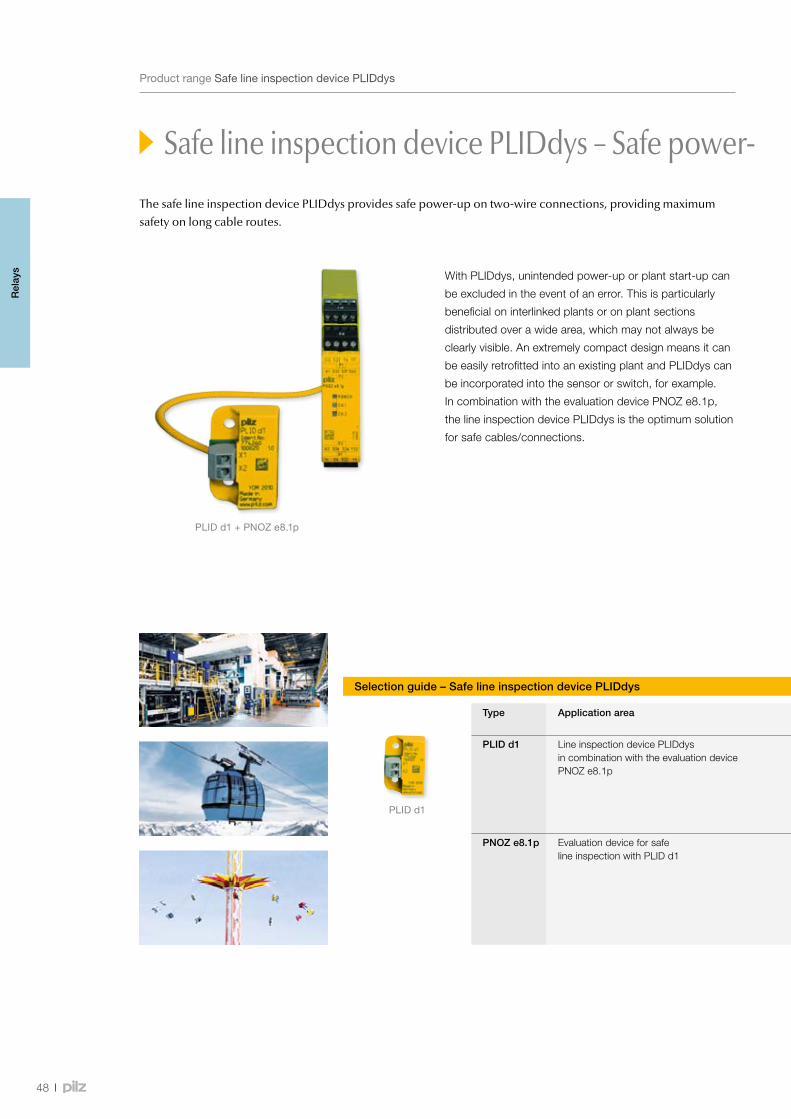
PLIDd1+PNOZ e8.1p
PLIDd1
48
ProductrangeSafelineinspectiondevicePLIDdys
Safe line inspection device PLIDdys – Safe power- up in conjunction with PNOZ e8.1p
With PLIDdys, unintended power-up or plant start-up can
be excluded in the event of an error. This is particularly
beneficial on interlinked plants or on plant sections
distributed over a wide area, which may not always be
clearly visible. An extremely compact design means it can
be easily retrofitted into an existing plant and PLIDdys can
be incorporated into the sensor or switch, for example.
In combination with the evaluation device PNOZ e8.1p,
the line inspection device PLIDdys is the optimum solution
for safe cables/connections.
Selection guide – Safe line inspection device PLIDdys
Type Application area Dimensions (L x W x H) in mm
Features Order number
PLID d1 Line inspection device PLIDdys in combination with the evaluation device PNOZ e8.1p
36 x 26 x 12.1 1) • Cable cross section of 0.5 mm² to 1.5 mm² • Maximum cable length 3,000 m • Cable resistance maximum 220 Ohm • Supply voltage 24 VDC • Weight 10 g • Temperature range -30 °C … +70 °C
• PLID d1 774 260 • PLID d1 C 3) 784 260
PNOZ e8.1p Evaluation device for safe line inspection with PLID d1
101/94 2) x 22.5 x 121 • Outputs using semiconductor technology: - 2 safety outputs - 2 auxiliary outputs
• Outputs: Voltage/current/rating: 24 VDC/1.5 A/40 W • Monitored or automatic reset can be selected • Monitoring of shorts across contacts can be selected for E-STOP application
• PNOZ e8.1p with spring-loaded terminals 784 198
• PNOZ e8.1p with plug-in screw terminals 774 198
1)Heightofversionwithspring-loadedterminal12.5 mm2)Heightwithspring-loadedterminals/plug-inscrewterminals
3)Versionwithspring-loadedterminal
The safe line inspection device PLIDdys provides safe power-up on two-wire connections, providing maximum safety on long cable routes.
Rel
ays
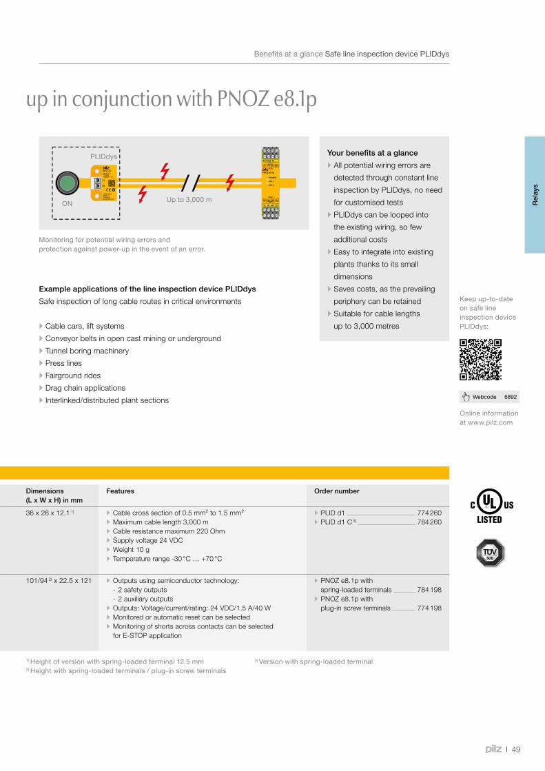
49
Webcode 6892
Safe line inspection device PLIDdys – Safe power- up in conjunction with PNOZ e8.1p
BenefitsataglanceSafelineinspectiondevicePLIDdys
Your benefits at a glance
•All potential wiring errors are
detected through constant line
inspection by PLIDdys, no need
for customised tests
•PLIDdys can be looped into
the existing wiring, so few
additional costs
•Easy to integrate into existing
plants thanks to its small
dimensions
•Saves costs, as the prevailing
periphery can be retained
•Suitable for cable lengths
up to 3,000 metres
Onlineinformationatwww.pilz.com
Keepup-to-dateonsafelineinspectiondevicePLIDdys:
Example applications of the line inspection device PLIDdys
Safe inspection of long cable routes in critical environments
•Cable cars, lift systems
•Conveyor belts in open cast mining or underground
•Tunnel boring machinery
•Press lines
•Fairground rides
•Drag chain applications
•Interlinked/distributed plant sections
Monitoringforpotentialwiringerrorsandprotectionagainstpower-upintheeventofanerror.
Selection guide – Safe line inspection device PLIDdys
Type Application area Dimensions (L x W x H) in mm
Features Order number
PLID d1 Line inspection device PLIDdys in combination with the evaluation device PNOZ e8.1p
36 x 26 x 12.1 1) • Cable cross section of 0.5 mm² to 1.5 mm² • Maximum cable length 3,000 m • Cable resistance maximum 220 Ohm • Supply voltage 24 VDC • Weight 10 g • Temperature range -30 °C … +70 °C
• PLID d1 774 260 • PLID d1 C 3) 784 260
PNOZ e8.1p Evaluation device for safe line inspection with PLID d1
101/94 2) x 22.5 x 121 • Outputs using semiconductor technology: - 2 safety outputs - 2 auxiliary outputs
• Outputs: Voltage/current/rating: 24 VDC/1.5 A/40 W • Monitored or automatic reset can be selected • Monitoring of shorts across contacts can be selected for E-STOP application
• PNOZ e8.1p with spring-loaded terminals 784 198
• PNOZ e8.1p with plug-in screw terminals 774 198
1)Heightofversionwithspring-loadedterminal12.5 mm2)Heightwithspring-loadedterminals/plug-inscrewterminals
3)Versionwithspring-loadedterminal
PLIDdys
ON Upto3,000m Rel
ays
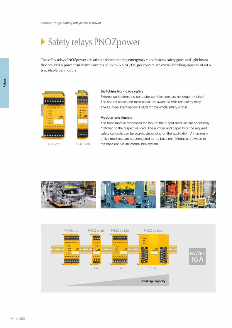
PNOZ po3pPNOZ p1p
PNOZ p1p PNOZ po3.1p PNOZ po3.2pPNOZ po3p
8 A 16 A4 A
50
ProductrangeSafetyrelaysPNOZpower
Switching high loads safely
External contactors and contactor combinations are no longer required.
The control circuit and main circuit are switched with one safety relay.
The EC type examination is valid for the whole safety circuit.
Modular and flexible
The base module processes the inputs; the output modules are specifically
matched to the respective load. The number and capacity of the required
safety contacts can be scaled, depending on the application. A maximum
of five modules can be connected to the base unit. Modules are wired to
the base unit via an internal bus system.
Safety relays PNOZpower
Breaking capacity
The safety relays PNOZpower are suitable for monitoring emergency stop devices, safety gates and light beam devices. PNOZpower can switch currents of up to 16 A AC/DC per contact. An overall breaking capacity of 40 A is available per module.
Rel
ays
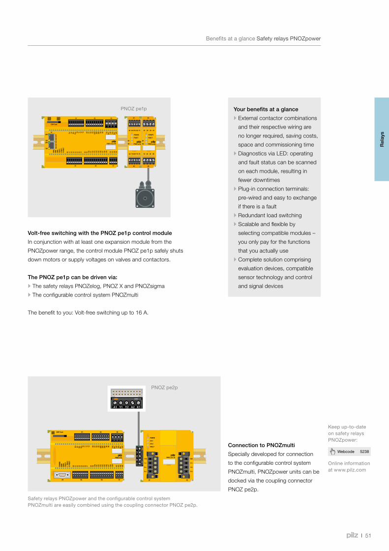
PNOZ pe1p
PNOZ pe2p
51
Webcode 5238
BenefitsataglanceSafetyrelaysPNOZpower
Your benefits at a glance
•External contactor combinations
and their respective wiring are
no longer required, saving costs,
space and commissioning time
•Diagnostics via LED: operating
and fault status can be scanned
on each module, resulting in
fewer downtimes
•Plug-in connection terminals:
pre-wired and easy to exchange
if there is a fault
•Redundant load switching
•Scalable and flexible by
selecting compatible modules –
you only pay for the functions
that you actually use
•Complete solution comprising
evaluation devices, compatible
sensor technology and control
and signal devices
Safety relays PNOZpower
Keepup-to-dateonsafetyrelaysPNOZpower:
Onlineinformationatwww.pilz.com
SafetyrelaysPNOZpowerandtheconfigurablecontrolsystemPNOZmultiareeasilycombinedusingthecouplingconnectorPNOZpe2p.
Connection to PNOZmulti
Specially developed for connection
to the configurable control system
PNOZmulti, PNOZpower units can be
docked via the coupling connector
PNOZ pe2p.
Volt-free switching with the PNOZ pe1p control module
In conjunction with at least one expansion module from the
PNOZpower range, the control module PNOZ pe1p safely shuts
down motors or supply voltages on valves and contactors.
The PNOZ pe1p can be driven via:
•The safety relays PNOZelog, PNOZ X and PNOZsigma
•The configurable control system PNOZmulti
The benefit to you: Volt-free switching up to 16 A.
Rel
ays
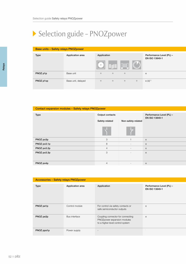
52
SelectionguideSafetyrelaysPNOZpower
Base units – Safety relays PNOZpower
Type Application area Application Performance Level (PL) – EN ISO 13849-1
Safety Integrity Level (SIL) CL – claim limit in accordance with IEC 62061
Number of expansion modules Supply voltage Dimensions (H x W x D) in mm
PNOZ p1p Base unit e 3 Min. 1, max. 4 expansion modules 24 VDC 94 x 45 x 135
PNOZ p1vp Base unit, delayed e (d) 1) 3 Min. 1, max. 8 expansion modules (max. 4 delayed and 4 instantaneous)
24 VDC 94 x 45 x 135
1)Valueappliesforinstantaneous(delayed)safetycontacts
Selection guide – PNOZpower
Contact expansion modules – Safety relays PNOZpower
Type Output contacts Performance Level (PL) – EN ISO 13849-1
Safety Integrity Level (SIL) CL – claim limit in accordance with IEC 62061
Number of expansion modules Dimensions (H x W x D) in mmSafety-related Non-safety-related AC1 AC3 DC1:
PNOZ po3p 3 1 e 3 240 V/4 A/960 VA - 24 V/4 A/96 W 94 x 22.5 x 121
PNOZ po3.1p 8 - e 3 240 V/8 A/2000 VA - 24 V/8 A/200 W 94 x 45 x 121
PNOZ po3.2p 4 - e 3 240 V/16 A/4000 VA - 24 V/16 A/400 W 94 x 90 x 135
PNOZ po3.3p 3 - e 3 240 V/16 A/4000 VA400 V/10 A/4000 VA500 V/8 A/4000 VA
240 V/3.0 kW400 V/5.5 kW500 V/4.0 kW
24 V/16 A/400 W 94 x 90 x 135
PNOZ po4p 4 - e 3 240 V/4 A/960 VA - 24 V/4 A/96 W 94 x 22.5 x 121
Accessories – Safety relays PNOZpower
Type Application area Application Performance Level (PL) – EN ISO 13849-1
Safety Integrity Level (SIL) CL – claim limit in accordance with IEC 62061
Number of expansion modules Supply voltage Dimensions (H x W x D) in mm
PNOZ pe1p Control module For control via safety contacts or safe semiconductor outputs
e 3 Min. 1, max. 4 expansion modules 24 VDC 94 x 22.5 x 121
PNOZ pe2p Bus interface Coupling connector for connecting PNOZpower expansion modules to a higher-level control system
e 3 Min. 1, max. 6 expansion modules 24 VDC 29 x 23.5 x 22
PNOZ pps1p Power supply - - - - 100 … 240 VAC 94 x 45 x 121
Rel
ays
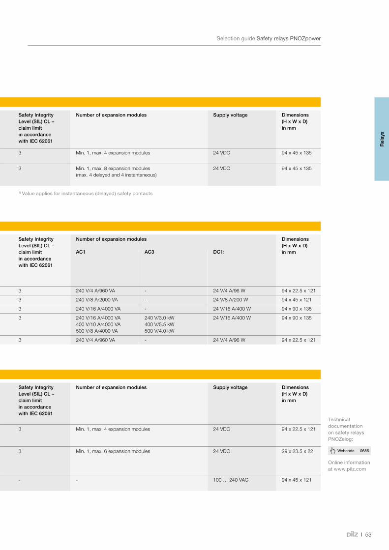
53
Webcode 0685
SelectionguideSafetyrelaysPNOZpower
Base units – Safety relays PNOZpower
Type Application area Application Performance Level (PL) – EN ISO 13849-1
Safety Integrity Level (SIL) CL – claim limit in accordance with IEC 62061
Number of expansion modules Supply voltage Dimensions (H x W x D) in mm
PNOZ p1p Base unit e 3 Min. 1, max. 4 expansion modules 24 VDC 94 x 45 x 135
PNOZ p1vp Base unit, delayed e (d) 1) 3 Min. 1, max. 8 expansion modules (max. 4 delayed and 4 instantaneous)
24 VDC 94 x 45 x 135
1)Valueappliesforinstantaneous(delayed)safetycontacts
Onlineinformationatwww.pilz.com
TechnicaldocumentationonsafetyrelaysPNOZelog:
Contact expansion modules – Safety relays PNOZpower
Type Output contacts Performance Level (PL) – EN ISO 13849-1
Safety Integrity Level (SIL) CL – claim limit in accordance with IEC 62061
Number of expansion modules Dimensions (H x W x D) in mmSafety-related Non-safety-related AC1 AC3 DC1:
PNOZ po3p 3 1 e 3 240 V/4 A/960 VA - 24 V/4 A/96 W 94 x 22.5 x 121
PNOZ po3.1p 8 - e 3 240 V/8 A/2000 VA - 24 V/8 A/200 W 94 x 45 x 121
PNOZ po3.2p 4 - e 3 240 V/16 A/4000 VA - 24 V/16 A/400 W 94 x 90 x 135
PNOZ po3.3p 3 - e 3 240 V/16 A/4000 VA400 V/10 A/4000 VA500 V/8 A/4000 VA
240 V/3.0 kW400 V/5.5 kW500 V/4.0 kW
24 V/16 A/400 W 94 x 90 x 135
PNOZ po4p 4 - e 3 240 V/4 A/960 VA - 24 V/4 A/96 W 94 x 22.5 x 121
Accessories – Safety relays PNOZpower
Type Application area Application Performance Level (PL) – EN ISO 13849-1
Safety Integrity Level (SIL) CL – claim limit in accordance with IEC 62061
Number of expansion modules Supply voltage Dimensions (H x W x D) in mm
PNOZ pe1p Control module For control via safety contacts or safe semiconductor outputs
e 3 Min. 1, max. 4 expansion modules 24 VDC 94 x 22.5 x 121
PNOZ pe2p Bus interface Coupling connector for connecting PNOZpower expansion modules to a higher-level control system
e 3 Min. 1, max. 6 expansion modules 24 VDC 29 x 23.5 x 22
PNOZ pps1p Power supply - - - - 100 … 240 VAC 94 x 45 x 121
Rel
ays
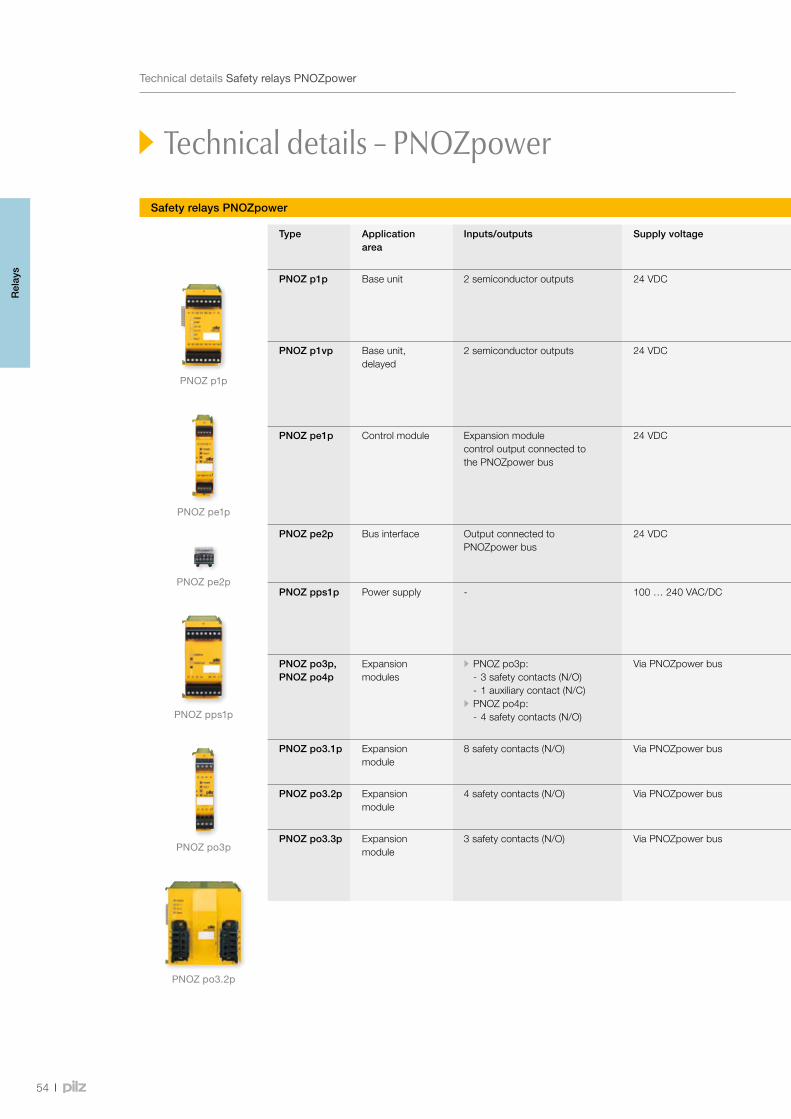
PNOZ p1p
PNOZ pe1p
PNOZ pe2p
PNOZ pps1p
PNOZ po3p
PNOZ po3.2p
54
TechnicaldetailsSafetyrelaysPNOZpower
Safety relays PNOZpower
Technical details – PNOZpower
Type Application area
Inputs/outputs Supply voltage Features Order number
Plug-in screw terminals
PNOZ p1p Base unit 2 semiconductor outputs 24 VDC • Dual-channel wiring, with or without detection of shorts across contacts • Monitored or automatic reset can be selected • Connection between PNOZ p1p and expansion modules via PNOZpower bus, using jumpers on the back of the unit
773 300
PNOZ p1vp Base unit, delayed
2 semiconductor outputs 24 VDC • Dual-channel wiring, with or without detection of shorts across contacts • Monitored or automatic reset can be selected • Delay time can be selected via rotary switch and potentiometer • Connection between PNOZ p1vp and expansion modules via PNOZpower bus, using jumpers on the back of the unit
• 30 s 773 950 • 300 s 773 951
PNOZ pe1p Control module Expansion module control output connected to the PNOZpower bus
24 VDC • 1-channel operation, without detection of shorts across contacts • 2-channel operation, with or without detection of shorts across contacts • Connection between PNOZ pe1p and expansion modules via PNOZpower bus, using jumpers on the back of the unit
• Status indicator for output relay, supply voltage and fault • Connection for feedback loop
773 900
PNOZ pe2p Bus interface Output connected to PNOZpower bus
24 VDC • Control via safety contacts or safe semiconductor outputs • 1-channel operation, without detection of shorts across contacts • Connection between PNOZ pe2p and expansion modules via the PNOZpower bus
779 125
PNOZ pps1p Power supply - 100 … 240 VAC/DC • Galvanic isolation • Short circuit-proof • 24 VDC at the plug-in connector on the back of the unit for the PNOZpower bus and at the terminals • LEDs for supply voltage, output voltage and fault
773 200
PNOZ po3p,PNOZ po4p
Expansion modules
• PNOZ po3p: - 3 safety contacts (N/O) - 1 auxiliary contact (N/C)
• PNOZ po4p: - 4 safety contacts (N/O)
Via PNOZpower bus • 2-channel operation with the ability to detect short circuits via the base unit • LEDs for switch status of channels 1/2, supply voltage and fault
• PNOZ po3p 773 634 • PNOZ po4p 773 635
PNOZ po3.1p Expansion module
8 safety contacts (N/O) Via PNOZpower bus 773 630
PNOZ po3.2p Expansion module
4 safety contacts (N/O) Via PNOZpower bus 773 631
PNOZ po3.3p Expansion module
3 safety contacts (N/O) Via PNOZpower bus • 2-channel operation with the ability to detect short circuits via the base unit • LEDs for switch status of channels 1/2, supply voltage and fault • Suitable for safety-related switching of loads with utilisation category AC3 (e.g. motor) • External start/stop input for non-safety-related load switching
773 632
Rel
ays
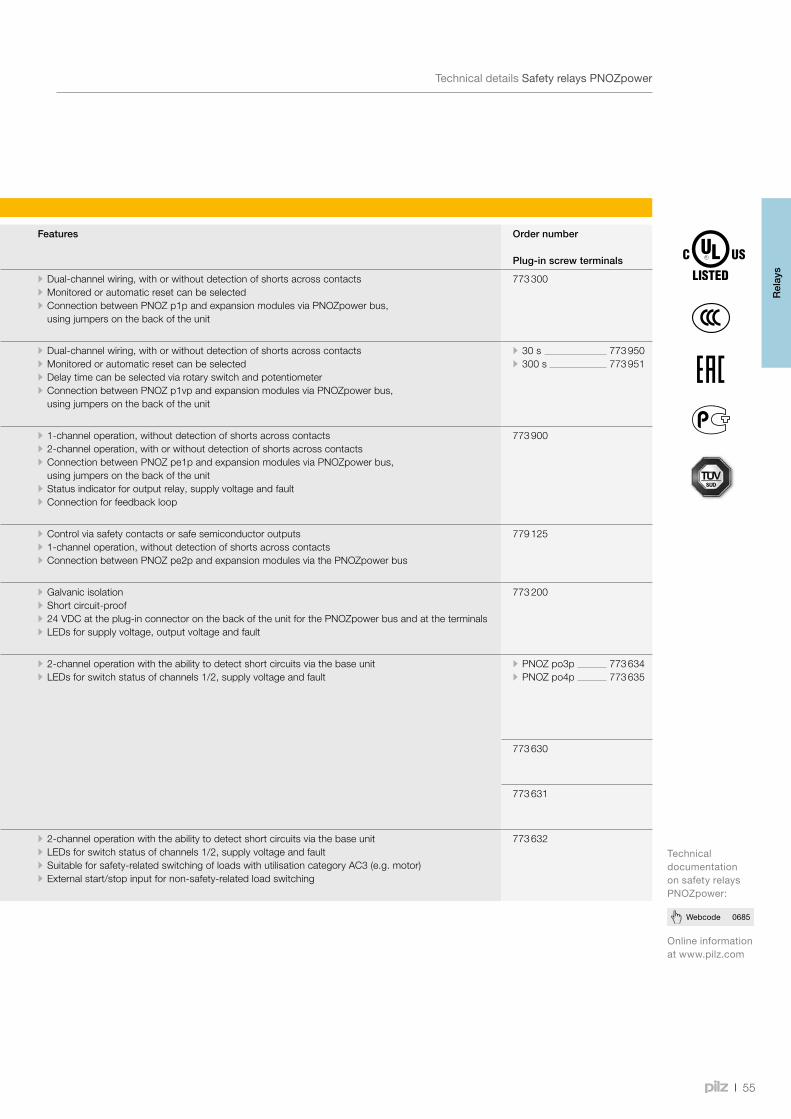
55
Webcode 0685
TechnicaldetailsSafetyrelaysPNOZpower
Safety relays PNOZpower
Type Application area
Inputs/outputs Supply voltage Features Order number
Plug-in screw terminals
PNOZ p1p Base unit 2 semiconductor outputs 24 VDC • Dual-channel wiring, with or without detection of shorts across contacts • Monitored or automatic reset can be selected • Connection between PNOZ p1p and expansion modules via PNOZpower bus, using jumpers on the back of the unit
773 300
PNOZ p1vp Base unit, delayed
2 semiconductor outputs 24 VDC • Dual-channel wiring, with or without detection of shorts across contacts • Monitored or automatic reset can be selected • Delay time can be selected via rotary switch and potentiometer • Connection between PNOZ p1vp and expansion modules via PNOZpower bus, using jumpers on the back of the unit
• 30 s 773 950 • 300 s 773 951
PNOZ pe1p Control module Expansion module control output connected to the PNOZpower bus
24 VDC • 1-channel operation, without detection of shorts across contacts • 2-channel operation, with or without detection of shorts across contacts • Connection between PNOZ pe1p and expansion modules via PNOZpower bus, using jumpers on the back of the unit
• Status indicator for output relay, supply voltage and fault • Connection for feedback loop
773 900
PNOZ pe2p Bus interface Output connected to PNOZpower bus
24 VDC • Control via safety contacts or safe semiconductor outputs • 1-channel operation, without detection of shorts across contacts • Connection between PNOZ pe2p and expansion modules via the PNOZpower bus
779 125
PNOZ pps1p Power supply - 100 … 240 VAC/DC • Galvanic isolation • Short circuit-proof • 24 VDC at the plug-in connector on the back of the unit for the PNOZpower bus and at the terminals • LEDs for supply voltage, output voltage and fault
773 200
PNOZ po3p,PNOZ po4p
Expansion modules
• PNOZ po3p: - 3 safety contacts (N/O) - 1 auxiliary contact (N/C)
• PNOZ po4p: - 4 safety contacts (N/O)
Via PNOZpower bus • 2-channel operation with the ability to detect short circuits via the base unit • LEDs for switch status of channels 1/2, supply voltage and fault
• PNOZ po3p 773 634 • PNOZ po4p 773 635
PNOZ po3.1p Expansion module
8 safety contacts (N/O) Via PNOZpower bus 773 630
PNOZ po3.2p Expansion module
4 safety contacts (N/O) Via PNOZpower bus 773 631
PNOZ po3.3p Expansion module
3 safety contacts (N/O) Via PNOZpower bus • 2-channel operation with the ability to detect short circuits via the base unit • LEDs for switch status of channels 1/2, supply voltage and fault • Suitable for safety-related switching of loads with utilisation category AC3 (e.g. motor) • External start/stop input for non-safety-related load switching
773 632
Onlineinformationatwww.pilz.com
TechnicaldocumentationonsafetyrelaysPNOZpower:
Rel
ays
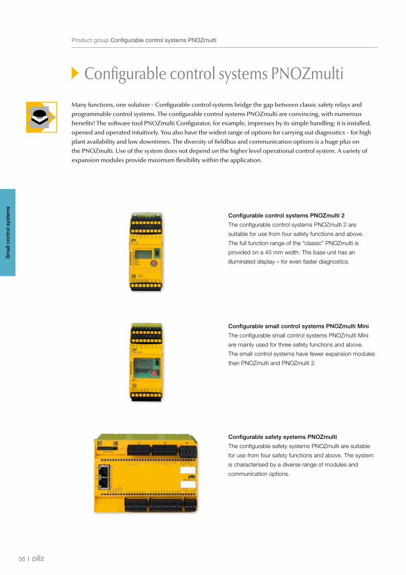
56
ProductgroupConfigurablecontrolsystemsPNOZmulti
Configurable control systems PNOZmulti
Many functions, one solution – Configurable control systems bridge the gap between classic safety relays and programmable control systems. The configurable control systems PNOZmulti are convincing, with numerous benefits! The software tool PNOZmulti Configurator, for example, impresses by its simple handling: it is installed, opened and operated intuitively. You also have the widest range of options for carrying out diagnostics – for high plant availability and low downtimes. The diversity of fieldbus and communication options is a huge plus on the PNOZmulti. Use of the system does not depend on the higher level operational control system. A variety of expansion modules provide maximum flexibility within the application.
Configurable control systems PNOZmulti 2
The configurable control systems PNOZmulti 2 are
suitable for use from four safety functions and above.
The full function range of the “classic” PNOZmulti is
provided on a 45 mm width. The base unit has an
illuminated display – for even faster diagnostics.
Configurable safety systems PNOZmulti
The configurable safety systems PNOZmulti are suitable
for use from four safety functions and above. The system
is characterised by a diverse range of modules and
communication options.
Configurable small control systems PNOZmulti Mini
The configurable small control systems PNOZmulti Mini
are mainly used for three safety functions and above.
The small control systems have fewer expansion modules
than PNOZmulti and PNOZmulti 2.
Sm
all c
ontr
ol s
yste
ms
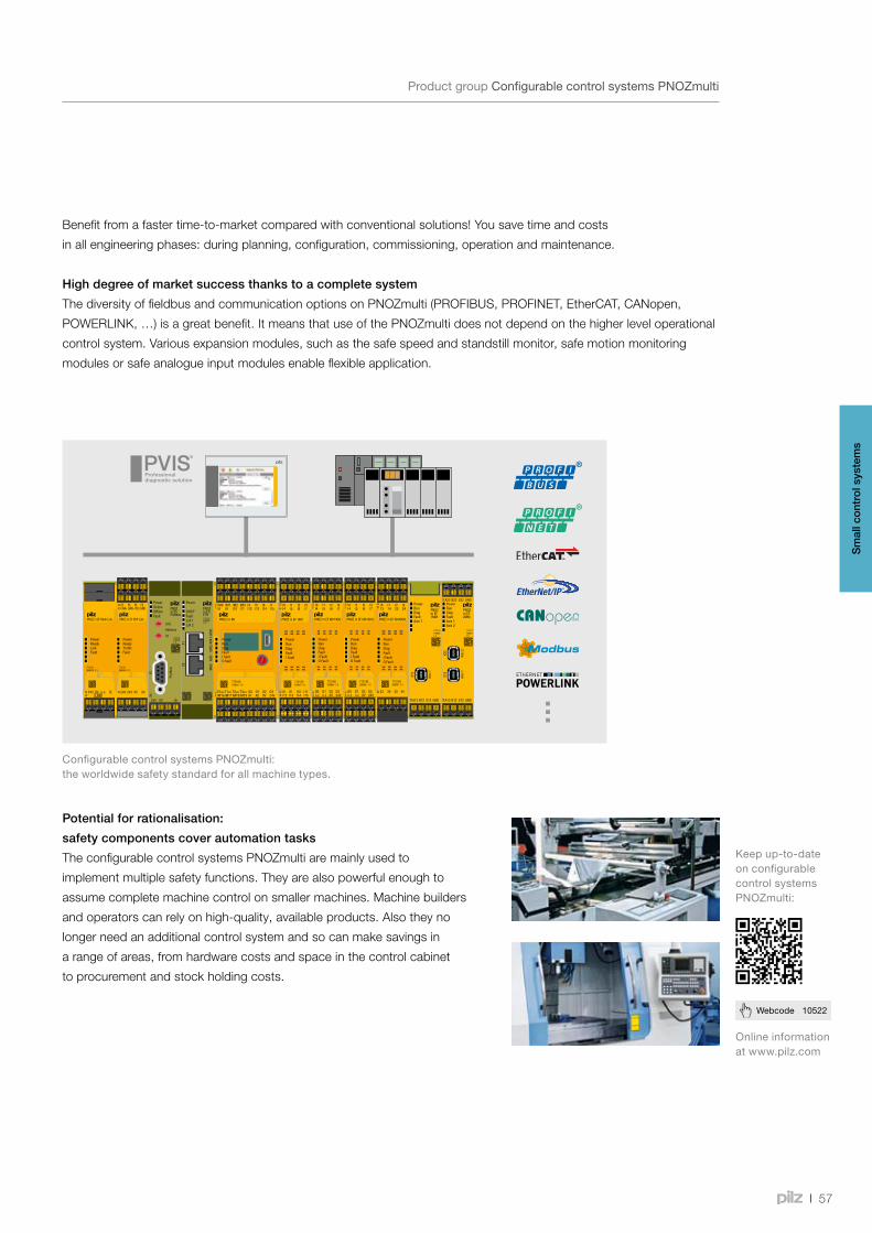
57
Webcode 10522
ProductgroupConfigurablecontrolsystemsPNOZmulti
Configurable control systems PNOZmulti
Benefit from a faster time-to-market compared with conventional solutions! You save time and costs
in all engineering phases: during planning, configuration, commissioning, operation and maintenance.
High degree of market success thanks to a complete system
The diversity of fieldbus and communication options on PNOZmulti (PROFIBUS, PROFINET, EtherCAT, CANopen,
POWERLINK, …) is a great benefit. It means that use of the PNOZmulti does not depend on the higher level operational
control system. Various expansion modules, such as the safe speed and standstill monitor, safe motion monitoring
modules or safe analogue input modules enable flexible application.
ConfigurablecontrolsystemsPNOZmulti:theworldwidesafetystandardforallmachinetypes.
Onlineinformationatwww.pilz.com
Keepup-to-dateonconfigurablecontrolsystemsPNOZmulti:
Potential for rationalisation:
safety components cover automation tasks
The configurable control systems PNOZmulti are mainly used to
implement multiple safety functions. They are also powerful enough to
assume complete machine control on smaller machines. Machine builders
and operators can rely on high-quality, available products. Also they no
longer need an additional control system and so can make savings in
a range of areas, from hardware costs and space in the control cabinet
to procurement and stock holding costs.
Sm
all c
ontr
ol s
yste
ms
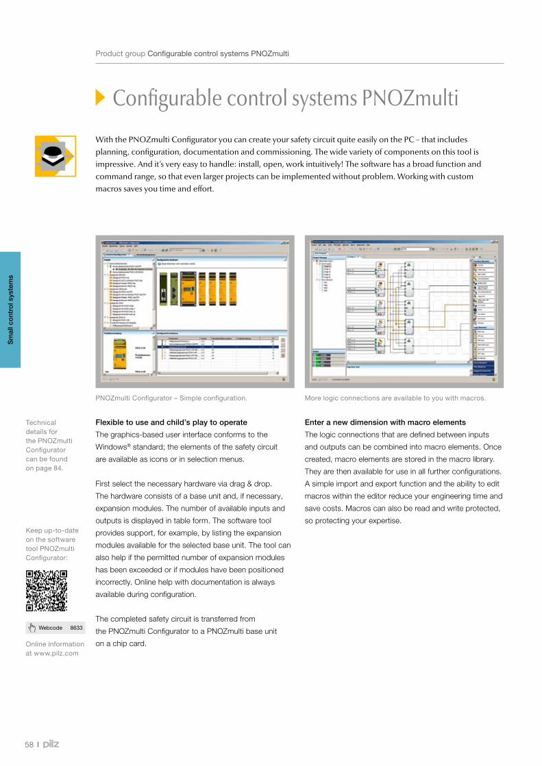
58
Webcode 8633
ProductgroupConfigurablecontrolsystemsPNOZmulti
Configurable control systems PNOZmulti
Enter a new dimension with macro elements
The logic connections that are defined between inputs
and outputs can be combined into macro elements. Once
created, macro elements are stored in the macro library.
They are then available for use in all further configurations.
A simple import and export function and the ability to edit
macros within the editor reduce your engineering time and
save costs. Macros can also be read and write protected,
so protecting your expertise.
PNOZmultiConfigurator–Simpleconfiguration.
Keepup-to-dateonthesoftwaretoolPNOZmultiConfigurator:
Onlineinformationatwww.pilz.com
Flexible to use and child’s play to operate
The graphics-based user interface conforms to the
Windows® standard; the elements of the safety circuit
are available as icons or in selection menus.
First select the necessary hardware via drag & drop.
The hardware consists of a base unit and, if necessary,
expansion modules. The number of available inputs and
outputs is displayed in table form. The software tool
provides support, for example, by listing the expansion
modules available for the selected base unit. The tool can
also help if the permitted number of expansion modules
has been exceeded or if modules have been positioned
incorrectly. Online help with documentation is always
available during configuration.
The completed safety circuit is transferred from
the PNOZmulti Configurator to a PNOZmulti base unit
on a chip card.
Morelogicconnectionsareavailabletoyouwithmacros.
With the PNOZmulti Configurator you can create your safety circuit quite easily on the PC – that includes planning, configuration, documentation and commissioning. The wide variety of components on this tool is impressive. And it’s very easy to handle: install, open, work intuitively! The software has a broad function and command range, so that even larger projects can be implemented without problem. Working with custom macros saves you time and effort.
Sm
all c
ontr
ol s
yste
ms
TechnicaldetailsforthePNOZmultiConfiguratorcanbefoundonpage84.
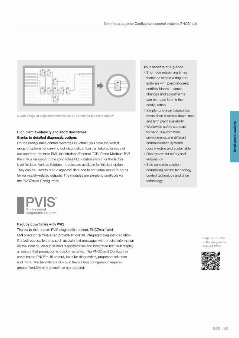
59
BenefitsataglanceConfigurablecontrolsystemsPNOZmulti
Configurable control systems PNOZmulti
Your benefits at a glance
•Short commissioning times
thanks to simple wiring and
software with preconfigured,
certified blocks – simple
changes and adjustments
can be made later in the
configuration
•Simple, universal diagnostics
mean short machine downtimes
and high plant availability
•Worldwide safety standard
for various automation
environments and different
communication systems,
cost effective and sustainable
•One system for safety and
automation
•Safe complete solution
comprising sensor technology,
control technology and drive
technology
Awiderangeoflogicconnectionscanbecombinedtoformamacro.
High plant availability and short downtimes
thanks to detailed diagnostic options
On the configurable control systems PNOZmulti you have the widest
range of options for carrying out diagnostics. You can take advantage of
our operator terminals PMI, the interface Ethernet TCP/IP and Modbus TCP,
the status message to the connected PLC control system or the higher
level fieldbus. Various fieldbus modules are available for this last option.
They can be used to read diagnostic data and to set virtual inputs/outputs
for non-safety-related outputs. The modules are simple to configure via
the PNOZmulti Configurator.
Keepup-to-dateonthediagnosticconceptPVIS:
Sm
all c
ontr
ol s
yste
ms
Reduce downtimes with PVIS
Thanks to the modern PVIS diagnostic concept, PNOZmulti and
PMI operator terminals can provide an overall, integrated diagnostic solution.
If a fault occurs, features such as plain text messages with precise information
on the location, clearly defined responsibilities and integrated first fault display
all ensure that production is quickly restarted. The PNOZmulti Configurator
contains the PNOZmulti project, texts for diagnostics, proposed solutions
and more. The benefits are obvious: there’s less configuration required,
greater flexibility and downtimes are reduced.
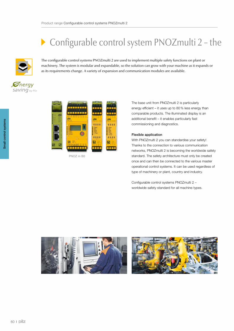
PNOZ m B0
60
Configurable control system PNOZmulti 2 – the future-proof solution
The configurable control systems PNOZmulti 2 are used to implement multiple safety functions on plant or machinery. The system is modular and expandable, so the solution can grow with your machine as it expands or as its requirements change. A variety of expansion and communication modules are available.
ProductrangeConfigurablecontrolsystemsPNOZmulti2
The base unit from PNOZmulti 2 is particularly
energy efficient – it uses up to 80 % less energy than
comparable products. The illuminated display is an
additional benefit – it enables particularly fast
commissioning and diagnostics.
Flexible application
With PNOZmulti 2 you can standardise your safety!
Thanks to the connection to various communication
networks, PNOZmulti 2 is becoming the worldwide safety
standard. The safety architecture must only be created
once and can then be connected to the various master
operational control systems. It can be used regardless of
type of machinery or plant, country and industry.
Configurable control systems PNOZmulti 2 –
worldwide safety standard for all machine types.
Sm
all c
ontr
ol s
yste
ms

7721321000021.0
PowerOnlineOfflineFault
24V
PNOZ m ESProfibus
0V
X10
X1
Address
X4
Prof
ibus
X1
7721300000051.0
Power
DHCPFaultL/A 1L/A 2
PNOZ m ESETH
X1X2
MAC
AD
D
0002
-484
1-00
00
I12
PNOZ m EF 16DI
I14 I15
000007 0.1772140
X4 X
2
I13I8 I9 I10 I11
PowerRunDiagFaultI Fault
X1 X
3
I0I4
I1I5
I2I6
I3I7
PNOZ m EF 4DI4DOR
000007 0.1772143
X2 33 34 43 44
PowerRunDiagFaultI FaultO Fault
X1 X
3
I013
I114
I223
I324
61
Webcode 10522
Expansionmodulesforvariousapplicationsandconnectiontocommonfieldbussystems–that’sflexibility.
ProductrangeConfigurablecontrolsystemsPNOZmulti2
Configurable control system PNOZmulti 2 – the future-proof solution
Sm
all c
ontr
ol s
yste
ms
Onlineinformationatwww.pilz.com
Keepup-to-dateonconfigurablecontrolsystemsPNOZmulti2:
Your benefits at a glance
•Short commissioning times
through simple wiring and
software tool PNOZmulti
Configurator
•Simple and economical
to expand by selecting
compatible modules
•Simple, user-friendly
diagnostics mean short
downtimes and high plant
availability
•One system for safety and
automation
•Fast time-to-market:
Inputs and outputs are freely
configurable
•Particularly energy efficient:
Base unit consumes up to 80 %
less energy than comparable
products
•Certified worldwide
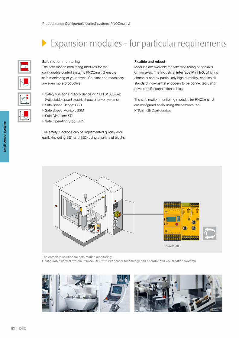
PNOZ m EF 4DI4DOR
000007 0.1772143
X2 3334
4344
Power
Run
Diag
Fault
I Fault
O Fault
X1 X
3
I013
I114
I223
I324
62
Expansion modules – for particular requirements
ProductrangeConfigurablecontrolsystemsPNOZmulti2
Safe motion monitoring
The safe motion monitoring modules for the
configurable control systems PNOZmulti 2 ensure
safe monitoring of your drives. So plant and machinery
are even more productive:
•Safety functions in accordance with EN 61800-5-2
(Adjustable speed electrical power drive systems)
•Safe Speed Range: SSR
•Safe Speed Monitor: SSM
•Safe Direction: SDI
•Safe Operating Stop: SOS
The safety functions can be implemented quickly and
easily (including SS1 and SS2) using a variety of blocks.
Flexible and robust
Modules are available for safe monitoring of one axis
or two axes. The industrial interface Mini I/O, which is
characterised by particularly high durability, enables all
standard incremental encoders to be connected using
drive-specific connection cables.
The safe motion monitoring modules for PNOZmulti 2
are configured easily using the software tool
PNOZmulti Configurator.
Thecompletesolutionforsafemotionmonitoring:ConfigurablecontrolsystemPNOZmulti2withPilzsensortechnologyandoperatorandvisualisationsystems.
PNOZmulti 2
Sm
all c
ontr
ol s
yste
ms

63
Expansion modules – for particular requirements
ProductrangeConfigurablecontrolsystemsPNOZmulti2
PNOZmulti 2 – with decentralised expansion
The configurable control systems PNOZmulti 2 can
be expanded using link modules for decentralisation and
for safe communication between multiple base units.
Safety functions on more complex plant and machinery
can thus be easily implemented.
Decentrally in the field
The PDP link module serves as the interface for the
decentralised modules PDP67 (protection type IP67) to
the base unit. As a result, the signals from the connected
sensors are directly forwarded to this from the field for
further processing. With up to 16 PDP67 modules on one
base unit the number of sensors that can be connected
increases by 64. This is what an economical solution
looks like!
Complex tasks – a team effort
The multi link module enables simple, safe data
exchange between several base units. Thanks to the
modular structure of the PNOZmulti 2 different topologies
can be implemented on one base unit with up to four
link modules. As a result, users can connect several
PNOZmulti units to implement safety functions for
complex plant and machinery.
ThedecentralisedmodulesPDP67canbeconnectedtothePNOZmulti 2viaalinkmodule–forcost-effective,simple,decentralisedexpansion.Alinkmoduleisalsoavailablefornetworkingseveralbaseunits.
Sm
all c
ontr
ol s
yste
ms
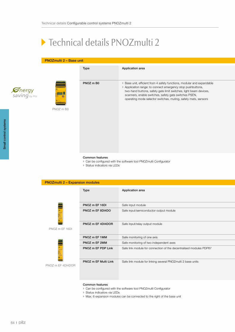
PNOZ m B0
PNOZ m EF 16DI
PNOZ m EF 4DI4DOR
64
TechnicaldetailsConfigurablecontrolsystemsPNOZmulti2
PNOZmulti 2 – Base unit
Technical details PNOZmulti 2
Type Application area Features Order number
Excl. terminals Spring-loaded terminals
Plug-in screw terminals
PNOZ m B0 • Base unit, efficient from 4 safety functions, modular and expandable • Application range: to connect emergency stop pushbuttons, two-hand buttons, safety gate limit switches, light beam devices, scanners, enable switches, safety gate switches PSEN, operating mode selector switches, muting, safety mats, sensors
• Base unit complies with PL e of EN ISO 13849-1 and SIL CL 3 of IEC 62061; the maximum achievable value depends on the application, e.g. number of outputs
• Configurable using PNOZmulti Configurator via chip card or USB interface
• Exchangeable program memory • 20 safe inputs, up to 8 of which can be configured as auxiliary outputs
• 4 safe semiconductor outputs, depending on the application up to PL e, SIL CL 3
• 4 test pulse outputs, up to 4 of which can be configured as standard outputs
• With illuminated display for error messages • State of the supply voltage, the inputs and outputs, status and device information, customised texts can be displayed
• Rotary knob for menu control
772 100
Mini USB cable • 3 m 312 992 • 5 m 312 993
• Chip card 8 kByte 1 piece 779 201
• Chip card 32 kByte 1 piece 779 211
751 008 (1 set) 750 008 (1 set)
Common features•Can be configured with the software tool PNOZmulti Configurator•Status indicators via LEDs
Type Application area Features Order number
Excl. terminals Spring-loaded terminals
Plug-in screw terminals
PNOZ m EF 16DI Safe input module 16 safe inputs 772 140 751 004 (1 set) 750 004 (1 set)
PNOZ m EF 8DI4DO Safe input/semiconductor output module • 8 safe inputs • 4 safe semiconductor outputs, depending on the application up to PL e, SIL CL 3
772 142 751 004 (1 set) 750 004 (1 set)
PNOZ m EF 4DI4DOR Safe input/relay output module • 4 safe inputs • Relay outputs: 4 safety outputs, depending on the application up to PL e, SIL CL 3
772 143 751 004 (1 set) 750 004 (1 set)
PNOZ m EF 1MM Safe monitoring of one axis Support of safe drive function in accordance with EN 61800-5-2 772 170 783 542 (1 set) 793 542 (1 set)
PNOZ m EF 2MM Safe monitoring of two independent axes Support of safe drive function in accordance with EN 61800-5-2 772 171 783 544 (1 set) 793 544 (1 set)
PNOZ m EF PDP Link Safe link module for connection of the decentralised modules PDP67 • Max. 4 PDP link modules to the left of the base unit • Max. 4 decentralised modules PDP67 F 8 DI ION (VA) or PDP67 F 8 DI ION HP (VA) to the link module
772 121 783 540 (1 set) 793 540 (1 set)
PNOZ m EF Multi Link Safe link module for linking several PNOZmulti 2 base units • Point-to-point connection via 4-core shielded and twisted-pair cable
• Transfer of 32 bit input data and 32 bit output data (virtual I/Os)
• Max. 4 Multi link modules to the left of the base unit
772 120 783 538 (1 set) 793 538 (1 set)
Common features•Can be configured with the software tool PNOZmulti Configurator•Status indicators via LEDs •Max. 6 expansion modules can be connected to the right of the base unit
PNOZmulti 2 – Expansion modules
Sm
all c
ontr
ol s
yste
ms
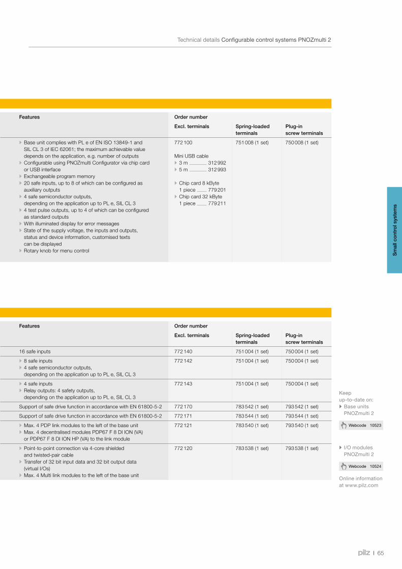
65
Webcode 10524
Webcode 10523
Type Application area Features Order number
Excl. terminals Spring-loaded terminals
Plug-in screw terminals
PNOZ m B0 • Base unit, efficient from 4 safety functions, modular and expandable • Application range: to connect emergency stop pushbuttons, two-hand buttons, safety gate limit switches, light beam devices, scanners, enable switches, safety gate switches PSEN, operating mode selector switches, muting, safety mats, sensors
• Base unit complies with PL e of EN ISO 13849-1 and SIL CL 3 of IEC 62061; the maximum achievable value depends on the application, e.g. number of outputs
• Configurable using PNOZmulti Configurator via chip card or USB interface
• Exchangeable program memory • 20 safe inputs, up to 8 of which can be configured as auxiliary outputs
• 4 safe semiconductor outputs, depending on the application up to PL e, SIL CL 3
• 4 test pulse outputs, up to 4 of which can be configured as standard outputs
• With illuminated display for error messages • State of the supply voltage, the inputs and outputs, status and device information, customised texts can be displayed
• Rotary knob for menu control
772 100
Mini USB cable • 3 m 312 992 • 5 m 312 993
• Chip card 8 kByte 1 piece 779 201
• Chip card 32 kByte 1 piece 779 211
751 008 (1 set) 750 008 (1 set)
Common features•Can be configured with the software tool PNOZmulti Configurator•Status indicators via LEDs
TechnicaldetailsConfigurablecontrolsystemsPNOZmulti2
Type Application area Features Order number
Excl. terminals Spring-loaded terminals
Plug-in screw terminals
PNOZ m EF 16DI Safe input module 16 safe inputs 772 140 751 004 (1 set) 750 004 (1 set)
PNOZ m EF 8DI4DO Safe input/semiconductor output module • 8 safe inputs • 4 safe semiconductor outputs, depending on the application up to PL e, SIL CL 3
772 142 751 004 (1 set) 750 004 (1 set)
PNOZ m EF 4DI4DOR Safe input/relay output module • 4 safe inputs • Relay outputs: 4 safety outputs, depending on the application up to PL e, SIL CL 3
772 143 751 004 (1 set) 750 004 (1 set)
PNOZ m EF 1MM Safe monitoring of one axis Support of safe drive function in accordance with EN 61800-5-2 772 170 783 542 (1 set) 793 542 (1 set)
PNOZ m EF 2MM Safe monitoring of two independent axes Support of safe drive function in accordance with EN 61800-5-2 772 171 783 544 (1 set) 793 544 (1 set)
PNOZ m EF PDP Link Safe link module for connection of the decentralised modules PDP67 • Max. 4 PDP link modules to the left of the base unit • Max. 4 decentralised modules PDP67 F 8 DI ION (VA) or PDP67 F 8 DI ION HP (VA) to the link module
772 121 783 540 (1 set) 793 540 (1 set)
PNOZ m EF Multi Link Safe link module for linking several PNOZmulti 2 base units • Point-to-point connection via 4-core shielded and twisted-pair cable
• Transfer of 32 bit input data and 32 bit output data (virtual I/Os)
• Max. 4 Multi link modules to the left of the base unit
772 120 783 538 (1 set) 793 538 (1 set)
Common features•Can be configured with the software tool PNOZmulti Configurator•Status indicators via LEDs •Max. 6 expansion modules can be connected to the right of the base unit
Onlineinformationatwww.pilz.com
• I/OmodulesPNOZmulti 2
Keepup-to-dateon:• BaseunitsPNOZmulti 2
Sm
all c
ontr
ol s
yste
ms

PNOZ m ES PROFIBUS
PNOZ m ES RS232PNOZ m ES ETH
PNOZ m ES EtherCAT
PNOZ m ES Profinet
PNOZ m ES CANopen
PNOZ m ES Powerlink
PNOZ m ES EtherNetIP
Ethernet RS232
66
PNOZmulti 2 – Communication modules
TechnicaldetailsConfigurablecontrolsystemsPNOZmulti2
Technical details PNOZmulti 2
Type Application area Features Order number
Excl. terminals Spring-loaded terminals
Plug-in screw terminals
PNOZ m ES ETH Communication module with Ethernet/Modbus TCP interface
• Number of ETH interfaces: 2 • Transmission rate 10 MBit/s or 100 MBit/s • Connection to fieldbus via RJ45 connector
772 130 - -
PNOZ m ES RS232 Communication module with serial interface
With serial interface RS232 772 131 783 538 (1 set) 793 538 (1 set)
PNOZ m ES PROFIBUS Communication module/ fieldbus module PROFIBUS-DP (slave)
• Station addresses from 0 ... 99, selected via rotary switch • Transmission rate: max. 12 MBit/s • Connection to fieldbus via female 9-pin D-Sub connector
772 132 783 542 (1 set) 793 542 (1 set)
PNOZ m ES CANopen Communication module/ fieldbus module CANopen (Slave, CiA 301 V4.2.0)
• Station addresses from 0 ... 99, selected via rotary switch • Transmission rate: Max. 1 MBit/s • Transmission rate selected via rotary switch • Connection to fieldbus via female 9-pin D-Sub connector
772 134 783 542 (1 set) 793 542 (1 set)
PNOZ m ES EtherCAT Communication module/ fieldbus module EtherCAT (slave, CANopen over EtherCAT)
• Transmission rate: 100 MBit/s • max. 148 bytes TxPDO and 20 bytes RxPDO • Connection to fieldbus via RJ45 connector
772 136 783 542 (1 set) 793 542 (1 set)
PNOZ m ES Powerlink Communication module/ fieldbus module Powerlink V2 (slave, CANopen over Ethernet)
• Transmission rate: 100 MBit/s • Connection to fieldbus via RJ45 connector
772 119 783 542 (1 set) 793 542 (1 set)
PNOZ m ES Profinet Communication module/ fieldbus module Profinet (I/O-Device)
• Transmission rate: 100 MBit/s • Connection to fieldbus via RJ45 connector
772 138 783 542 (1 set) 793 542 (1 set)
PNOZ m ES EtherNet/IP Communication module/ fieldbus module Ethernet/IP (Adapter)
• Transmission rate: 100 MBit/s • IP address is set via DIP switch on the front of the unit • Connection to fieldbus via RJ45 connector
772 137 783 542 (1 set) 793 542 (1 set)
Common features•Can be configured with the software tool
PNOZmulti Configurator•Status indicators via LEDs •Max. 1 communication and 1 fieldbus module
can be connected to the left of the base unit
Sm
all c
ontr
ol s
yste
ms
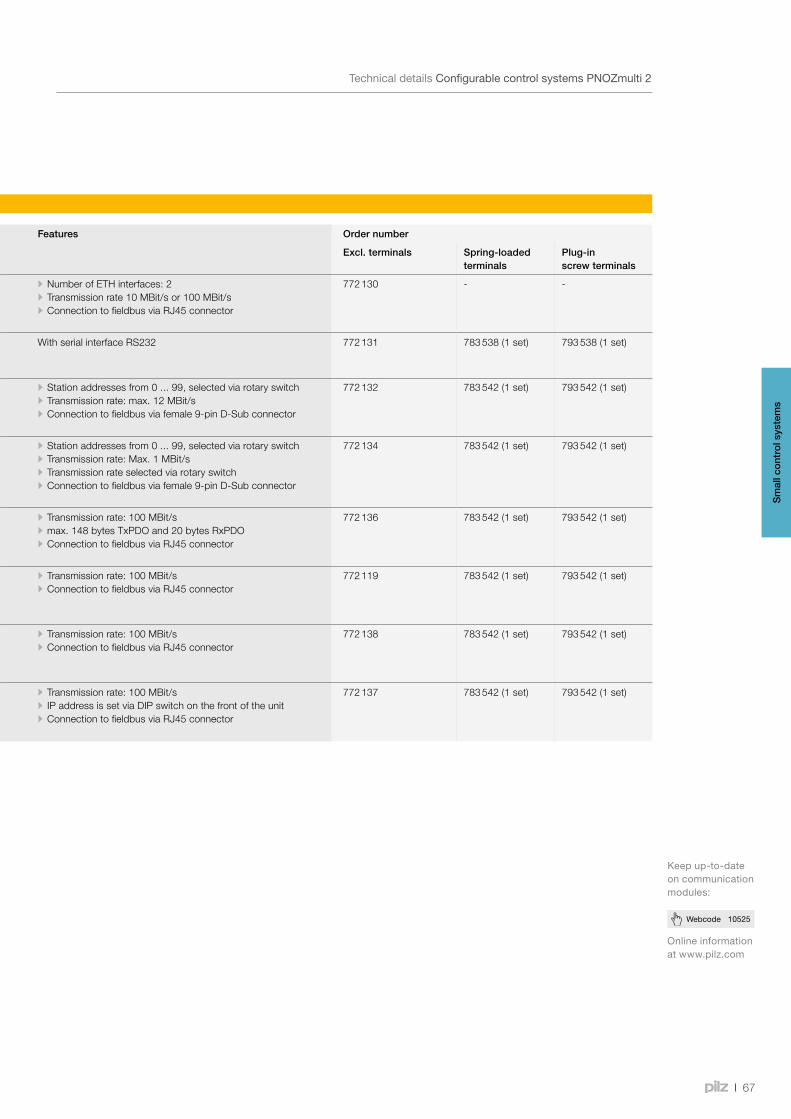
67
Webcode 10525
Keepup-to-dateoncommunicationmodules:
TechnicaldetailsConfigurablecontrolsystemsPNOZmulti2
Onlineinformationatwww.pilz.com
Type Application area Features Order number
Excl. terminals Spring-loaded terminals
Plug-in screw terminals
PNOZ m ES ETH Communication module with Ethernet/Modbus TCP interface
• Number of ETH interfaces: 2 • Transmission rate 10 MBit/s or 100 MBit/s • Connection to fieldbus via RJ45 connector
772 130 - -
PNOZ m ES RS232 Communication module with serial interface
With serial interface RS232 772 131 783 538 (1 set) 793 538 (1 set)
PNOZ m ES PROFIBUS Communication module/ fieldbus module PROFIBUS-DP (slave)
• Station addresses from 0 ... 99, selected via rotary switch • Transmission rate: max. 12 MBit/s • Connection to fieldbus via female 9-pin D-Sub connector
772 132 783 542 (1 set) 793 542 (1 set)
PNOZ m ES CANopen Communication module/ fieldbus module CANopen (Slave, CiA 301 V4.2.0)
• Station addresses from 0 ... 99, selected via rotary switch • Transmission rate: Max. 1 MBit/s • Transmission rate selected via rotary switch • Connection to fieldbus via female 9-pin D-Sub connector
772 134 783 542 (1 set) 793 542 (1 set)
PNOZ m ES EtherCAT Communication module/ fieldbus module EtherCAT (slave, CANopen over EtherCAT)
• Transmission rate: 100 MBit/s • max. 148 bytes TxPDO and 20 bytes RxPDO • Connection to fieldbus via RJ45 connector
772 136 783 542 (1 set) 793 542 (1 set)
PNOZ m ES Powerlink Communication module/ fieldbus module Powerlink V2 (slave, CANopen over Ethernet)
• Transmission rate: 100 MBit/s • Connection to fieldbus via RJ45 connector
772 119 783 542 (1 set) 793 542 (1 set)
PNOZ m ES Profinet Communication module/ fieldbus module Profinet (I/O-Device)
• Transmission rate: 100 MBit/s • Connection to fieldbus via RJ45 connector
772 138 783 542 (1 set) 793 542 (1 set)
PNOZ m ES EtherNet/IP Communication module/ fieldbus module Ethernet/IP (Adapter)
• Transmission rate: 100 MBit/s • IP address is set via DIP switch on the front of the unit • Connection to fieldbus via RJ45 connector
772 137 783 542 (1 set) 793 542 (1 set)
Common features•Can be configured with the software tool
PNOZmulti Configurator•Status indicators via LEDs •Max. 1 communication and 1 fieldbus module
can be connected to the left of the base unit
Sm
all c
ontr
ol s
yste
ms
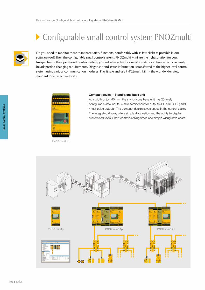
PNOZ mm0.1pPNOZ mm0p PNOZ mm0.2p
PNOZ mm0.1p
68
ProductrangeConfigurablesmallcontrolsystemsPNOZmultiMini
Configurable small control system PNOZmulti Mini
Do you need to monitor more than three safety functions, comfortably with as few clicks as possible in one software tool? Then the configurable small control systems PNOZmulti Mini are the right solution for you. Irrespective of the operational control system, you will always have a one-stop safety solution, which can easily be adapted to changing requirements. Diagnostic and status information is transferred to the higher level control system using various communication modules. Play it safe and use PNOZmulti Mini – the worldwide safety standard for all machine types.
Compact device – Stand-alone base unit
At a width of just 45 mm, the stand-alone base unit has 20 freely
configurable safe inputs, 4 safe semiconductor outputs (PL e/SIL CL 3) and
4 test pulse outputs. The compact design saves space in the control cabinet.
The integrated display offers simple diagnostics and the ability to display
customised texts. Short commissioning times and simple wiring save costs.
Sm
all c
ontr
ol s
yste
ms

PNOZ mm0pCRC: 0x810804.06.2009
69
Webcode 10517
BenefitsataglanceConfigurablesmallcontrolsystemsPNOZmultiMini
Configurable small control system PNOZmulti Mini
Keepup-to-dateontheconfigurablesmallcontrolsystemsPNOZmultiMini:
Onlineinformationatwww.pilz.com
Your benefits at a glance
•Efficient from three safety
functions onwards
•The software tool PNOZmulti
Configurator saves you time
and costs in all engineering
phases
•Maximum flexibility: Inputs and
outputs are freely configurable
•Saves lots of space in the
control cabinet due to the
compact design
•Reduced downtimes thanks to
PVIS support
•Customer texts can be
displayed
•Worldwide safety standard
for all machine types
Genial device – Base unit is modular and expandable
The base unit PNOZ mm0.1p is ready to meet growing requirements. It has the same technical features as
the PNOZ mm0p. The difference: it is modular and expandable. By selecting the appropriate modules and performing
a simple configuration, you can expand your application easily and economically. Expand to the left using safe link and
communication modules. Contact expansion modules from the PNOZsigma product range are available to multiply
the relay contacts on the right-hand side.
Communicative device – Base unit with Multi-Link inside
In addition to the functionality of the PNOZ mm0.1p, the base unit PNOZ mm0.2p also provides an integrated
multi-link interface. This removes the need for an additional module, saving you costs. As a result, it is easy to link
and exchange data between several base units PNOZmulti Mini and between PNOZmulti Mini and PNOZmulti
and PNOZmulti 2.
Simplediagnostics:integrateddisplayforshowinginformationanddiagnostics
Simpleoverview:via6LEDs–noexternalmeasuringdevicesrequired
Simpleconfigurationwith
thePNOZmultiConfigurator
viaUSBinterface
Rapidassemblyviaspringclips:noneedfortools
Valuesareeasytorequestthankstoa
rotaryknobwithkeyfunction
(pushandturn)
Rapidinstallation:innovativespring-loadedterminals,chambersoperatedindividually(withoptionalscrewterminals)
Safefrommanipulation:
settingelementshavealockable
coverandpasswordprotection
Configurableinputs/outputs
Sm
all c
ontr
ol s
yste
ms
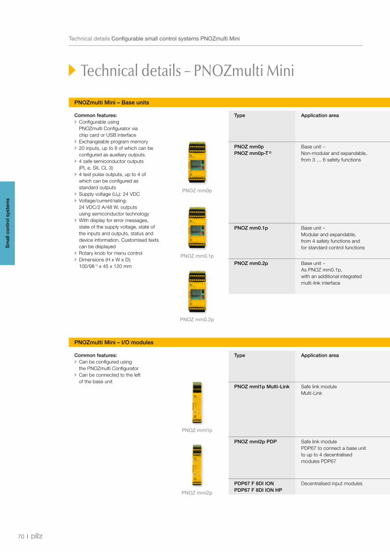
PNOZ mm0p
PNOZ mm0.1p
PNOZ mm0.2p
PNOZ mml1p
PNOZ mml2p
70
TechnicaldetailsConfigurablesmallcontrolsystemsPNOZmultiMini
PNOZmulti Mini – Base units
Technical details – PNOZmulti Mini
Type Application area Features Order number
Excl. terminals Push-in spring terminals
Plug-in screw terminals
PNOZ mm0pPNOZ mm0p-T 2)
Base unit – Non-modular and expandable, from 3 … 6 safety functions
Application range: to connect emergency stop pushbuttons, two-hand buttons, safety gate limit switches, light beam devices, scanners, enable switches, safety gate switches PSEN, operating mode selector switches, muting, safety mats, sensors
• PNOZ mm0p 772 000 • PNOZ mm0p-T 772 010
Mini USB cable • 3 m 312 992 • 5 m 312 993
• Chip card 8 kByte 1 piece 779 201
• Chip card 32 kByte 1 piece 779 211
751 008 (1 set)
750 008(1 set)
PNOZ mm0.1p Base unit – Modular and expandable, from 4 safety functions and for standard control functions
• As PNOZ mm0p • Expandable to the left using the link modules PNOZ mml1p Multi-Link, PNOZ mml2p PDP and a communication module PNOZ mmc1p ETH or PNOZ mmc2p serial. A fieldbus module may also be connected
• Expandable to the right using a contact expansion module PNOZsigma: PNOZ s22 or s7, s7.1, s7.2, s10, s11
• Decentralisation: PDP67 modules to connect sensor technology • PVIS support
772 001 751 008 (1 set)
750 008(1 set)
PNOZ mm0.2p Base unit – As PNOZ mm0.1p, with an additional integrated multi-link interface
772 002 751 008 (1 set)
750 008(1 set)
Common features: • Configurable using PNOZmulti Configurator via chip card or USB interface
• Exchangeable program memory • 20 inputs, up to 8 of which can be configured as auxiliary outputs.
• 4 safe semiconductor outputs (PL e, SIL CL 3)
• 4 test pulse outputs, up to 4 of which can be configured as standard outputs
• Supply voltage (UB): 24 VDC • Voltage/current/rating: 24 VDC/2 A/48 W, outputs using semiconductor technology
• With display for error messages, state of the supply voltage, state of the inputs and outputs, status and device information. Customised texts can be displayed
• Rotary knob for menu control • Dimensions (H x W x D): 100/98 1) x 45 x 120 mm
PNOZmulti Mini – I/O modules
Type Application area Features Order number
Excl. terminals Push-in spring terminals
Plug-in screw terminals
PNOZ mml1p Multi-Link Safe link module Multi-Link
• Link module to safely connect base units PNOZmulti Mini, PNOZmulti and PNOZmulti 2
• Point-to-point connection via 4-core shielded and twisted-pair cable
• 32 virtual inputs and 32 virtual outputs • Max. four PNOZ mml1p units can be connected to the left of the base unit
• Dimensions (H x W x D) in mm: 100 x 22.5 x 120
772 020 783 538 (1 set)
793 538 (1 set)
PNOZ mml2p PDP Safe link module PDP67 to connect a base unit to up to 4 decentralised modules PDP67
• Ability to connect up to four expansion modules to the left of the base unit PNOZ mm0.1p or mm0.2p
• Max. four decentralised input modules PDP67 can be connected to an expansion module (16 sensors with a maximum configuration)
• Dimensions (H x W x D) in mm: 98/100 1) x 22.5 x 120
772 021 783 540 (1 set)
793 540 (1 set)
PDP67 F 8DI ION PDP67 F 8DI ION HP
Decentralised input modules • For information please refer to pages 88/89 - - -
1)Heightwithspring-loadedterminals/plug-inscrewterminals2) Extended
temperaturerange
Common features: • Can be configured using the PNOZmulti Configurator
• Can be connected to the left of the base unit
Sm
all c
ontr
ol s
yste
ms
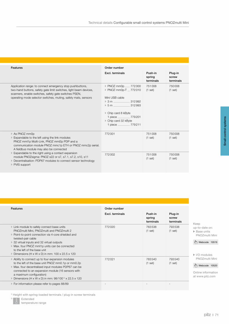
71
Webcode 10520
Webcode 10519
TechnicaldetailsConfigurablesmallcontrolsystemsPNOZmultiMini
PNOZmulti Mini – Base units
Type Application area Features Order number
Excl. terminals Push-in spring terminals
Plug-in screw terminals
PNOZ mm0pPNOZ mm0p-T 2)
Base unit – Non-modular and expandable, from 3 … 6 safety functions
Application range: to connect emergency stop pushbuttons, two-hand buttons, safety gate limit switches, light beam devices, scanners, enable switches, safety gate switches PSEN, operating mode selector switches, muting, safety mats, sensors
• PNOZ mm0p 772 000 • PNOZ mm0p-T 772 010
Mini USB cable • 3 m 312 992 • 5 m 312 993
• Chip card 8 kByte 1 piece 779 201
• Chip card 32 kByte 1 piece 779 211
751 008 (1 set)
750 008(1 set)
PNOZ mm0.1p Base unit – Modular and expandable, from 4 safety functions and for standard control functions
• As PNOZ mm0p • Expandable to the left using the link modules PNOZ mml1p Multi-Link, PNOZ mml2p PDP and a communication module PNOZ mmc1p ETH or PNOZ mmc2p serial. A fieldbus module may also be connected
• Expandable to the right using a contact expansion module PNOZsigma: PNOZ s22 or s7, s7.1, s7.2, s10, s11
• Decentralisation: PDP67 modules to connect sensor technology • PVIS support
772 001 751 008 (1 set)
750 008(1 set)
PNOZ mm0.2p Base unit – As PNOZ mm0.1p, with an additional integrated multi-link interface
772 002 751 008 (1 set)
750 008(1 set)
Onlineinformationatwww.pilz.com
• I/OmodulesPNOZmulti Mini
PNOZmulti Mini – I/O modules
Type Application area Features Order number
Excl. terminals Push-in spring terminals
Plug-in screw terminals
PNOZ mml1p Multi-Link Safe link module Multi-Link
• Link module to safely connect base units PNOZmulti Mini, PNOZmulti and PNOZmulti 2
• Point-to-point connection via 4-core shielded and twisted-pair cable
• 32 virtual inputs and 32 virtual outputs • Max. four PNOZ mml1p units can be connected to the left of the base unit
• Dimensions (H x W x D) in mm: 100 x 22.5 x 120
772 020 783 538 (1 set)
793 538 (1 set)
PNOZ mml2p PDP Safe link module PDP67 to connect a base unit to up to 4 decentralised modules PDP67
• Ability to connect up to four expansion modules to the left of the base unit PNOZ mm0.1p or mm0.2p
• Max. four decentralised input modules PDP67 can be connected to an expansion module (16 sensors with a maximum configuration)
• Dimensions (H x W x D) in mm: 98/100 1) x 22.5 x 120
772 021 783 540 (1 set)
793 540 (1 set)
PDP67 F 8DI ION PDP67 F 8DI ION HP
Decentralised input modules • For information please refer to pages 88/89 - - -
1)Heightwithspring-loadedterminals/plug-inscrewterminals2) Extended
temperaturerange
Keepup-to-dateon:• BaseunitsPNOZmulti Mini
Sm
all c
ontr
ol s
yste
ms
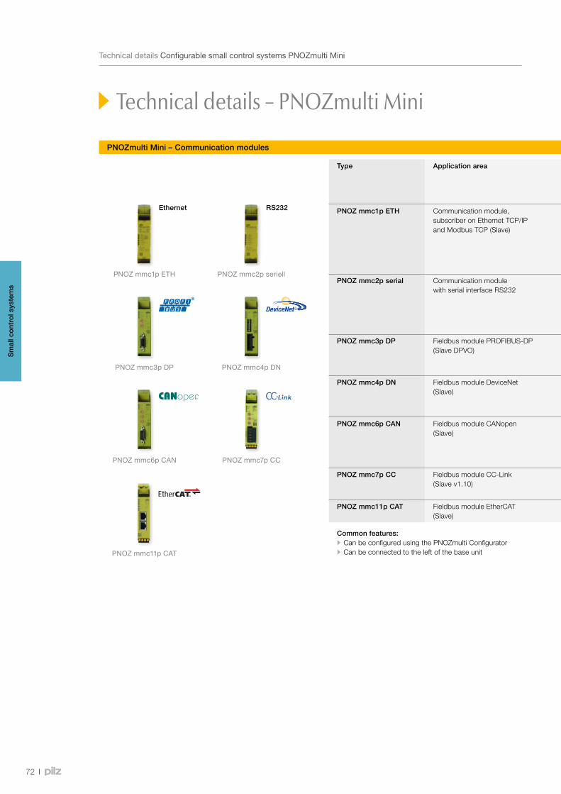
PNOZ mmc3p DP
PNOZ mmc2p seriellPNOZ mmc1p ETH
PNOZ mmc6p CAN
PNOZ mmc4p DN
PNOZ mmc7p CC
PNOZ mmc11p CAT
Ethernet RS232
72
TechnicaldetailsConfigurablesmallcontrolsystemsPNOZmultiMini
PNOZmulti Mini – Communication modules
Technical details – PNOZmulti Mini
Type Application area Features Order number
Excl. terminals Push-in spring terminals
Plug-in screw terminals
PNOZ mmc1p ETH Communication module, subscriber on Ethernet TCP/IP and Modbus TCP (Slave)
• 2 Ethernet interfaces • Transmission rate 10 MBit/s • Status indicators via LEDs • Max. 1 communication module can be connected to the left of the base unit; a fieldbus module can also be connected
• Connected to base unit via a link on the back of the unit • Dimensions (H x W x D): 100 x 22.5 x 120 mm
772 030 - -
PNOZ mmc2p serial Communication module with serial interface RS232
• 1 serial interface RS232 • Status indicators via LEDs • Max. 1 communication module can be connected to the left of the base unit; a fieldbus module can also be connected
• Connected to base unit via a link on the back of the unit • Dimensions (H x W x D): 100 x 22.5 x 120 mm
772 031 783 538 (1 set)
793 538 (1 set)
PNOZ mmc3p DP Fieldbus module PROFIBUS-DP (Slave DPVO)
• Station addresses from 0 ... 99, selected via rotary switch • Transmission rate: max. 12 MBit/s • Connection to fieldbus: via 9-pin female D-Sub connector • Dimensions (H x W x D) in mm: 100 x 22.5 x 115
772 032 783 542 (1 set)
793 542 (1 set)
PNOZ mmc4p DN Fieldbus module DeviceNet (Slave)
• Station addresses from 0 … 63, selected via DIP switch • Transmission rate: 500 kBit/s • Connection to fieldbus: via 5-pin Combicon plug-in connector • Dimensions (H x W x D) in mm: 100 x 22.5 x 110
772 033 783 542 (1 set)
793 542 (1 set)
PNOZ mmc6p CAN Fieldbus module CANopen (Slave)
• Station addresses from 0 ... 99, selected via rotary switch • Transmission rate: Max. 1 MBit/s • Transmission rate selected via rotary switch • Connection to fieldbus: via 9-pin female D-Sub connector • Dimensions (H x W x D) in mm: 100 x 22.5 x 115
772 034 783 542 (1 set)
793 542 (1 set)
PNOZ mmc7p CC Fieldbus module CC-Link (Slave v1.10)
• Transmission rate: Max. 10 MBit/s • Connection to fieldbus: via 5-pin Combicon plug-in connector • Dimensions (H x W x D) in mm: 100 x 22.5 x 110
772 035 783 542 (1 set)
793 542 (1 set)
PNOZ mmc11p CAT Fieldbus module EtherCAT (Slave)
• Transmission rate: Max. 100 MBit/s • Dimensions (H x W x D) in mm: 100 x 22.5 x 115
772 036 783 542 (1 set)
793 542 (1 set)
Common features: • Can be configured using the PNOZmulti Configurator • Can be connected to the left of the base unit
Sm
all c
ontr
ol s
yste
ms

73
Webcode 10521
TechnicaldetailsConfigurablesmallcontrolsystemsPNOZmultiMini
PNOZmulti Mini – Communication modules
Type Application area Features Order number
Excl. terminals Push-in spring terminals
Plug-in screw terminals
PNOZ mmc1p ETH Communication module, subscriber on Ethernet TCP/IP and Modbus TCP (Slave)
• 2 Ethernet interfaces • Transmission rate 10 MBit/s • Status indicators via LEDs • Max. 1 communication module can be connected to the left of the base unit; a fieldbus module can also be connected
• Connected to base unit via a link on the back of the unit • Dimensions (H x W x D): 100 x 22.5 x 120 mm
772 030 - -
PNOZ mmc2p serial Communication module with serial interface RS232
• 1 serial interface RS232 • Status indicators via LEDs • Max. 1 communication module can be connected to the left of the base unit; a fieldbus module can also be connected
• Connected to base unit via a link on the back of the unit • Dimensions (H x W x D): 100 x 22.5 x 120 mm
772 031 783 538 (1 set)
793 538 (1 set)
PNOZ mmc3p DP Fieldbus module PROFIBUS-DP (Slave DPVO)
• Station addresses from 0 ... 99, selected via rotary switch • Transmission rate: max. 12 MBit/s • Connection to fieldbus: via 9-pin female D-Sub connector • Dimensions (H x W x D) in mm: 100 x 22.5 x 115
772 032 783 542 (1 set)
793 542 (1 set)
PNOZ mmc4p DN Fieldbus module DeviceNet (Slave)
• Station addresses from 0 … 63, selected via DIP switch • Transmission rate: 500 kBit/s • Connection to fieldbus: via 5-pin Combicon plug-in connector • Dimensions (H x W x D) in mm: 100 x 22.5 x 110
772 033 783 542 (1 set)
793 542 (1 set)
PNOZ mmc6p CAN Fieldbus module CANopen (Slave)
• Station addresses from 0 ... 99, selected via rotary switch • Transmission rate: Max. 1 MBit/s • Transmission rate selected via rotary switch • Connection to fieldbus: via 9-pin female D-Sub connector • Dimensions (H x W x D) in mm: 100 x 22.5 x 115
772 034 783 542 (1 set)
793 542 (1 set)
PNOZ mmc7p CC Fieldbus module CC-Link (Slave v1.10)
• Transmission rate: Max. 10 MBit/s • Connection to fieldbus: via 5-pin Combicon plug-in connector • Dimensions (H x W x D) in mm: 100 x 22.5 x 110
772 035 783 542 (1 set)
793 542 (1 set)
PNOZ mmc11p CAT Fieldbus module EtherCAT (Slave)
• Transmission rate: Max. 100 MBit/s • Dimensions (H x W x D) in mm: 100 x 22.5 x 115
772 036 783 542 (1 set)
793 542 (1 set)
Common features: • Can be configured using the PNOZmulti Configurator • Can be connected to the left of the base unit
Onlineinformationatwww.pilz.com
Keepup-to-dateonthecommuni-cationmodulesPNOZmultiMini
Sm
all c
ontr
ol s
yste
ms

PNOZ ma1p
PNOZ m1p ETH
74
ProductrangeConfigurablesafetysystemsPNOZmulti
Configurable safety system PNOZmulti
The configurable safety system PNOZmulti is ideal when several safety functions are to be implemented on a machine. Instead of wiring, you can simply configure your safety circuit on a PC. PNOZmulti is multifunctional, freely configurable and tailor-made for use in many areas of mechanical engineering.
Monitoring analogue input signals safely
The safe analogue input module PNOZ ma1p provides two independent, safe inputs.
Up to eight limit values can be defined for each input with just a few clicks of the mouse in
the PNOZmulti Configurator. The inputs are suitable for connecting transducers or encoders
with standardised 10 V voltage signals or 20 mA current signals. As users you benefit from
rapid commissioning and reduced wiring. With its analogue input module, the PNOZmulti is
particularly suitable for the process engineering sector, cable car and chair lift design and
burner controls.
The safety system PNOZmulti monitors safety functions such as E-STOP, safety gates, light beam devices,
two-hand and many more. All safety functions are created with the software tool PNOZmulti Configurator.
The hardware configuration with the selection of base unit and expansion modules can also be made easily
via the PNOZmulti Configurator. So you can reduce your engineering times and get to market quicker.
You can then save the completed configuration on to a chip card. From there it is transferred to the base unit.
Sm
all c
ontr
ol s
yste
ms
The right module for every requirement …
If your plant expands, the PNOZmulti simply expands
with it. Expansion modules are available to extend the
modular system; these can be used in any combination
to suit the requirement:
•Input and output modules,
e.g. the safe analogue input module
•Fieldbus modules
•Safe speed and standstill monitors
•Safe link modules for the safe interconnection of
several PNOZmulti base units or the safe
interconnection of decentralised periphery
All PNOZmulti base units have 20 inputs,
4 safe semiconductor outputs and 2 relay outputs.
Versions are available with serial or ETH interface.
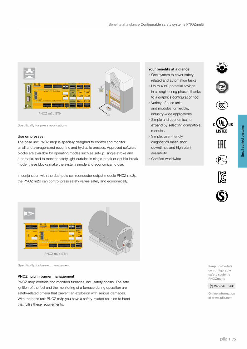
PNOZ m3p ETH
PNOZ m2p ETH
75
Webcode 5245
BenefitsataglanceConfigurablesafetysystemsPNOZmulti
Configurable safety system PNOZmulti
Keepup-to-dateonconfigurablesafetysystemsPNOZmulti:
Onlineinformationatwww.pilz.com
Your benefits at a glance
•One system to cover safety-
related and automation tasks
•Up to 40 % potential savings
in all engineering phases thanks
to a graphics configuration tool
•Variety of base units
and modules for flexible,
industry-wide applications
•Simple and economical to
expand by selecting compatible
modules
•Simple, user-friendly
diagnostics mean short
downtimes and high plant
availability
•Certified worldwide
Use on presses
The base unit PNOZ m2p is specially designed to control and monitor
small and average-sized eccentric and hydraulic presses. Approved software
blocks are available for operating modes such as set-up, single-stroke and
automatic, and to monitor safety light curtains in single-break or double-break
mode; these blocks make the system simple and economical to use.
In conjunction with the dual-pole semiconductor output module PNOZ mo3p,
the PNOZ m2p can control press safety valves safely and economically.
PNOZmulti in burner management
PNOZ m3p controls and monitors furnaces, incl. safety chains. The safe
ignition of the fuel and the monitoring of a furnace during operation are
safety-related criteria that prevent an explosion with serious damages.
With the base unit PNOZ m3p you have a safety-related solution to hand
that fulfils these requirements.
Specificallyforburnermanagement
Specificallyforpressapplications
Sm
all c
ontr
ol s
yste
ms
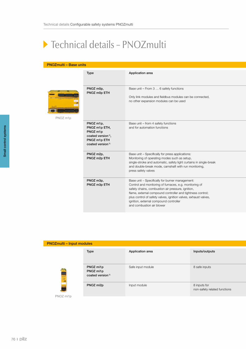
PNOZ mi1p
PNOZ m1p
76
TechnicaldetailsConfigurablesafetysystemsPNOZmulti
PNOZmulti – Base units
Technical details – PNOZmulti
Type Application area Features Order number
Excl. terminals Spring-loaded terminals
Plug-in screw terminals
PNOZ m0p,PNOZ m0p ETH
Base unit – From 3 … 6 safety functions
Only link modules and fieldbus modules can be connected, no other expansion modules can be used
• Application range: to connect emergency stop pushbuttons, two-hand buttons, safety gate limit switches, light beam devices, scanners, enable switches, safety gate switches PSEN, operating mode selector switches, muting, safety mats, sensors
• Configurable using PNOZmulti Configurator via chip card or RS 232 interface/Ethernet interface
• Exchangeable program memory • Diagnostic interface • Max. 1 fieldbus module can be connected • PNOZ m1p/PNOZ m2p/PNOZ m3p: Max. 8 expansion modules can be connected
• Inputs/outputs: - 20 freely configurable inputs, 4 test pulse outputs, 1 auxiliary output
- Outputs using semiconductor technology: 4 safety outputs
- Relay outputs: 2 safety contacts • Supply voltage (UB): 24 VDC • Voltage/current/rating:
- Outputs using semiconductor technology: 24 VDC/2 A/48 W - Relay outputs: DC1: 24 V/6 A/144 W
• Dimensions (H x W x D): 94 x 135 x 121 mm
• PNOZ m0p 773 110 • PNOZ m0p ETH 773 113
• Chip card 8 kByte 1 piece 779 201
• Chip card 32 kByte 1 piece 779 211
783 100 793 100
PNOZ m1p,PNOZ m1p ETH,PNOZ m1p coated version 1),PNOZ m1p ETH coated version 1)
Base unit – from 4 safety functions and for automation functions
• PNOZ m1p 773 100 • PNOZ m1p ETH 773 103 • PNOZ m1p coated version 1) 773 105
• PNOZ m1p ETH coated version 1) 773 104
783 100 793 100
PNOZ m2p,PNOZ m2p ETH
Base unit – Specifically for press applications: Monitoring of operating modes such as setup, single-stroke and automatic, safety light curtains in single-break and double-break mode, camshaft with run monitoring, press safety valves
• PNOZ m2p 773 120 • PNOZ m2p ETH 773 123
783 100 793 100
PNOZ m3p,PNOZ m3p ETH
Base unit – Specifically for burner management: Control and monitoring of furnaces, e.g. monitoring of safety chains, combustion air pressure, ignition, flame, external compound controller and tightness control; plus control of safety valves, ignition valves, exhaust valves, ignition, external compound controller and combustion air blower
• PNOZ m3p 773 125 • PNOZ m3p ETH 773 126
783 100 793 100
PNOZmulti – Input modules
Type Application area Inputs/outputs Features Order number
Excl. terminals Spring-loaded terminals
Plug-in screw terminals
PNOZ mi1pPNOZ mi1p coated version 1)
Safe input module 8 safe inputs • Max. 8 input modules can be connected to the base unit
• Connected to base unit via a link on the back of the unit
• PNOZ mi1p 773 400 • PNOZ mi1p coated version 1) 773 405
783 400 (1 set)
793 400 (1 set)
PNOZ mi2p Input module 8 inputs for non-safety related functions
773 410 783 400 (1 set)
793 400 (1 set)
1) Extendedtemperaturerange
Sm
all c
ontr
ol s
yste
ms
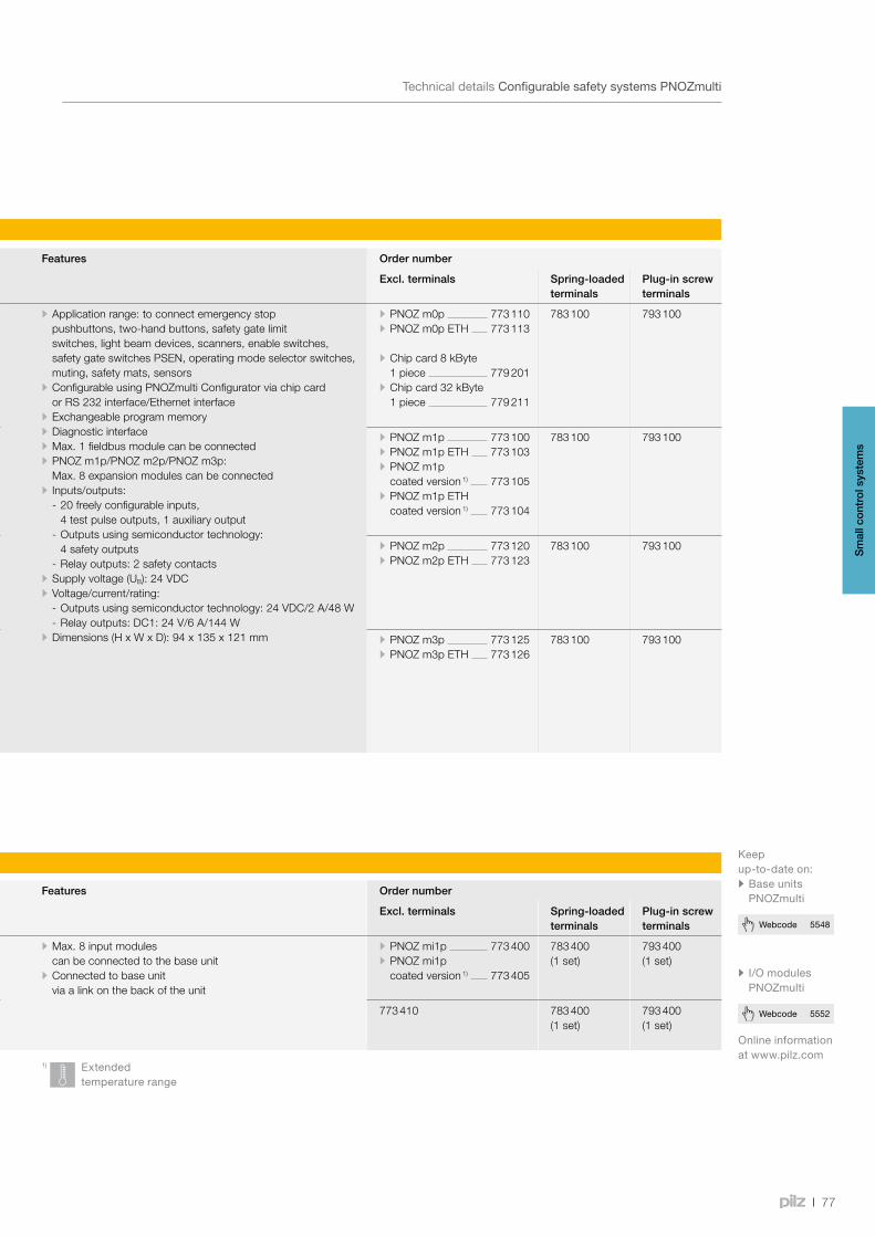
77
Webcode 5552
Webcode 5548
TechnicaldetailsConfigurablesafetysystemsPNOZmulti
PNOZmulti – Base units
Type Application area Features Order number
Excl. terminals Spring-loaded terminals
Plug-in screw terminals
PNOZ m0p,PNOZ m0p ETH
Base unit – From 3 … 6 safety functions
Only link modules and fieldbus modules can be connected, no other expansion modules can be used
• Application range: to connect emergency stop pushbuttons, two-hand buttons, safety gate limit switches, light beam devices, scanners, enable switches, safety gate switches PSEN, operating mode selector switches, muting, safety mats, sensors
• Configurable using PNOZmulti Configurator via chip card or RS 232 interface/Ethernet interface
• Exchangeable program memory • Diagnostic interface • Max. 1 fieldbus module can be connected • PNOZ m1p/PNOZ m2p/PNOZ m3p: Max. 8 expansion modules can be connected
• Inputs/outputs: - 20 freely configurable inputs, 4 test pulse outputs, 1 auxiliary output
- Outputs using semiconductor technology: 4 safety outputs
- Relay outputs: 2 safety contacts • Supply voltage (UB): 24 VDC • Voltage/current/rating:
- Outputs using semiconductor technology: 24 VDC/2 A/48 W - Relay outputs: DC1: 24 V/6 A/144 W
• Dimensions (H x W x D): 94 x 135 x 121 mm
• PNOZ m0p 773 110 • PNOZ m0p ETH 773 113
• Chip card 8 kByte 1 piece 779 201
• Chip card 32 kByte 1 piece 779 211
783 100 793 100
PNOZ m1p,PNOZ m1p ETH,PNOZ m1p coated version 1),PNOZ m1p ETH coated version 1)
Base unit – from 4 safety functions and for automation functions
• PNOZ m1p 773 100 • PNOZ m1p ETH 773 103 • PNOZ m1p coated version 1) 773 105
• PNOZ m1p ETH coated version 1) 773 104
783 100 793 100
PNOZ m2p,PNOZ m2p ETH
Base unit – Specifically for press applications: Monitoring of operating modes such as setup, single-stroke and automatic, safety light curtains in single-break and double-break mode, camshaft with run monitoring, press safety valves
• PNOZ m2p 773 120 • PNOZ m2p ETH 773 123
783 100 793 100
PNOZ m3p,PNOZ m3p ETH
Base unit – Specifically for burner management: Control and monitoring of furnaces, e.g. monitoring of safety chains, combustion air pressure, ignition, flame, external compound controller and tightness control; plus control of safety valves, ignition valves, exhaust valves, ignition, external compound controller and combustion air blower
• PNOZ m3p 773 125 • PNOZ m3p ETH 773 126
783 100 793 100
PNOZmulti – Input modules
Type Application area Inputs/outputs Features Order number
Excl. terminals Spring-loaded terminals
Plug-in screw terminals
PNOZ mi1pPNOZ mi1p coated version 1)
Safe input module 8 safe inputs • Max. 8 input modules can be connected to the base unit
• Connected to base unit via a link on the back of the unit
• PNOZ mi1p 773 400 • PNOZ mi1p coated version 1) 773 405
783 400 (1 set)
793 400 (1 set)
PNOZ mi2p Input module 8 inputs for non-safety related functions
773 410 783 400 (1 set)
793 400 (1 set)
1) Extendedtemperaturerange
Onlineinformationatwww.pilz.com
• I/OmodulesPNOZmulti
Keepup-to-dateon:• BaseunitsPNOZmulti
Sm
all c
ontr
ol s
yste
ms
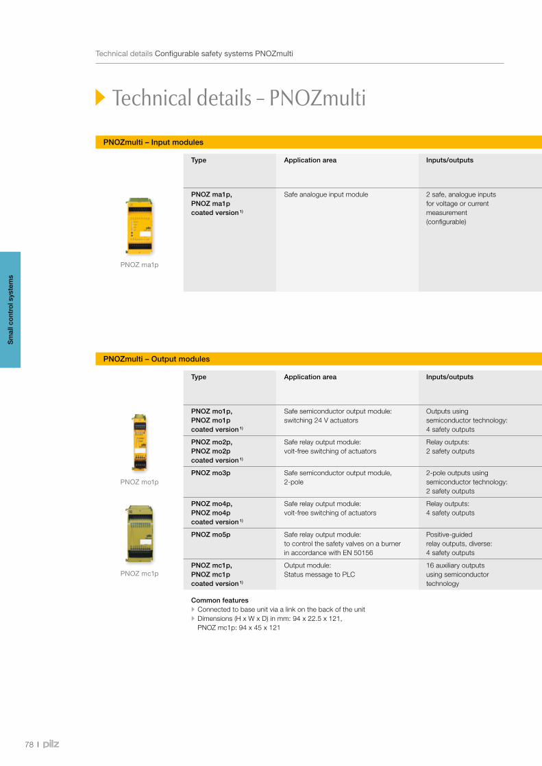
PNOZ ma1p
PNOZ mo1p
PNOZ mc1p
78
TechnicaldetailsConfigurablesafetysystemsPNOZmulti
PNOZmulti – Input modules
Technical details – PNOZmulti
Type Application area Inputs/outputs Features Order number
Excl. terminals Spring-loaded terminals
Plug-in screw terminals
PNOZ ma1p,PNOZ ma1p coated version 1)
Safe analogue input module 2 safe, analogue inputs for voltage or current measurement (configurable)
• Range monitoring (4 range limits can be configured)
• Threshold value monitoring (8 limit values can be configured)
• Voltage range: -10.24 … +10.2375 V • Current range: 0 … 25.59 mA • Can be connected to the left of the base unit • Max. 4 PNOZ ma1p units can be connected to the base unit • Status indicators • Dimensions (H x W x D) in mm: 94 x 45 x 121
• PNOZ ma1p 773 812 • PNOZ ma1p coated version 1) 773 813
783 700 (1 set)
793 700 (1 set)
PNOZmulti – Output modules
Type Application area Inputs/outputs Outputs: Voltage/current/rating
Features Order number
Excl. terminals Spring-loaded terminals
Plug-in screw terminals
PNOZ mo1p,PNOZ mo1p coated version 1)
Safe semiconductor output module: switching 24 V actuators
Outputs using semiconductor technology: 4 safety outputs
24 VDC/2 A/48 W • Max. 6 output modules can be connected to the right of the base unit
• PNOZ mo1p 773 500 • PNOZ mo1p coated version 1) 773 505
783 400 (1 set)
793 400 (1 set)
PNOZ mo2p,PNOZ mo2p coated version 1)
Safe relay output module: volt-free switching of actuators
Relay outputs: 2 safety outputs
DC1: 24 V/6 A • PNOZ mo2p 773 520 • PNOZ mo2p coated version 1) 773 525
783 520 (1 set)
793 520 (1 set)
PNOZ mo3p Safe semiconductor output module, 2-pole
2-pole outputs using semiconductor technology: 2 safety outputs
24 VDC/2 A • 773 510 783 400 (1 set)
793 400 (1 set)
PNOZ mo4p,PNOZ mo4p coated version 1)
Safe relay output module: volt-free switching of actuators
Relay outputs: 4 safety outputs
DC1: 24 V/6 A • PNOZ mo4p 773 536 • PNOZ mo4p coated version 1) 773 537
783 536 (1 set)
793 536 (1 set)
PNOZ mo5p Safe relay output module: to control the safety valves on a burner in accordance with EN 50156
Positive-guided relay outputs, diverse: 4 safety outputs
DC1: 24 V/6 A/144 W • 773 534 783 536 (1 set)
793 536 (1 set)
PNOZ mc1p,PNOZ mc1p coated version 1)
Output module: Status message to PLC
16 auxiliary outputs using semiconductor technology
- • Max. 8 output modules can be connected to the right of the base unit
• PNOZ mc1p 773 700 • PNOZ mc1p coated version 1) 773 705
783 700 (1 set)
793 700 (1 set)
Common features • Connected to base unit via a link on the back of the unit • Dimensions (H x W x D) in mm: 94 x 22.5 x 121, PNOZ mc1p: 94 x 45 x 121
1) Extendedtemperaturerange
Sm
all c
ontr
ol s
yste
ms
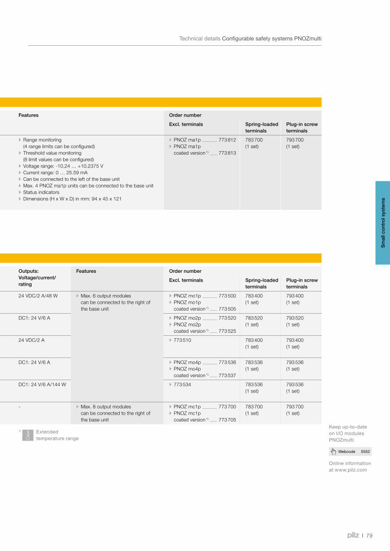
79
Webcode 5552
TechnicaldetailsConfigurablesafetysystemsPNOZmulti
PNOZmulti – Input modules
Type Application area Inputs/outputs Features Order number
Excl. terminals Spring-loaded terminals
Plug-in screw terminals
PNOZ ma1p,PNOZ ma1p coated version 1)
Safe analogue input module 2 safe, analogue inputs for voltage or current measurement (configurable)
• Range monitoring (4 range limits can be configured)
• Threshold value monitoring (8 limit values can be configured)
• Voltage range: -10.24 … +10.2375 V • Current range: 0 … 25.59 mA • Can be connected to the left of the base unit • Max. 4 PNOZ ma1p units can be connected to the base unit • Status indicators • Dimensions (H x W x D) in mm: 94 x 45 x 121
• PNOZ ma1p 773 812 • PNOZ ma1p coated version 1) 773 813
783 700 (1 set)
793 700 (1 set)
PNOZmulti – Output modules
Type Application area Inputs/outputs Outputs: Voltage/current/rating
Features Order number
Excl. terminals Spring-loaded terminals
Plug-in screw terminals
PNOZ mo1p,PNOZ mo1p coated version 1)
Safe semiconductor output module: switching 24 V actuators
Outputs using semiconductor technology: 4 safety outputs
24 VDC/2 A/48 W • Max. 6 output modules can be connected to the right of the base unit
• PNOZ mo1p 773 500 • PNOZ mo1p coated version 1) 773 505
783 400 (1 set)
793 400 (1 set)
PNOZ mo2p,PNOZ mo2p coated version 1)
Safe relay output module: volt-free switching of actuators
Relay outputs: 2 safety outputs
DC1: 24 V/6 A • PNOZ mo2p 773 520 • PNOZ mo2p coated version 1) 773 525
783 520 (1 set)
793 520 (1 set)
PNOZ mo3p Safe semiconductor output module, 2-pole
2-pole outputs using semiconductor technology: 2 safety outputs
24 VDC/2 A • 773 510 783 400 (1 set)
793 400 (1 set)
PNOZ mo4p,PNOZ mo4p coated version 1)
Safe relay output module: volt-free switching of actuators
Relay outputs: 4 safety outputs
DC1: 24 V/6 A • PNOZ mo4p 773 536 • PNOZ mo4p coated version 1) 773 537
783 536 (1 set)
793 536 (1 set)
PNOZ mo5p Safe relay output module: to control the safety valves on a burner in accordance with EN 50156
Positive-guided relay outputs, diverse: 4 safety outputs
DC1: 24 V/6 A/144 W • 773 534 783 536 (1 set)
793 536 (1 set)
PNOZ mc1p,PNOZ mc1p coated version 1)
Output module: Status message to PLC
16 auxiliary outputs using semiconductor technology
- • Max. 8 output modules can be connected to the right of the base unit
• PNOZ mc1p 773 700 • PNOZ mc1p coated version 1) 773 705
783 700 (1 set)
793 700 (1 set)
Common features • Connected to base unit via a link on the back of the unit • Dimensions (H x W x D) in mm: 94 x 22.5 x 121, PNOZ mc1p: 94 x 45 x 121
1) Extendedtemperaturerange
Onlineinformationatwww.pilz.com
Keepup-to-dateonI/OmodulesPNOZmulti
Sm
all c
ontr
ol s
yste
ms
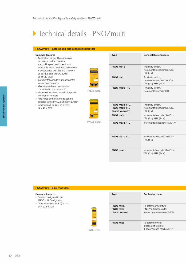
PNOZ ms1p
PNOZ ml1p
PNOZ ms4p
80
TechnicaldetailsConfigurablesafetysystemsPNOZmulti
Technical details – PNOZmulti
PNOZmulti – Safe speed and standstill monitors
Type Connectable encoders Features Order number
Excl. terminals Spring-loaded terminals
Plug-in screw terminals
PNOZ ms1p Proximity switch, incremental encoder Sin/Cos, TTL (5 V)
• Monitoring of 2 independent axes (8 limit frequencies can be selected)
• Connection per axis: 1 incremental encoder or 2 proximity switches or one of each
• Encoder types can be selected in the PNOZmulti Configurator • Proximity detectors are connected directly to the terminals
773 800 783 800 (1 set)
793 800 (1 set)
PNOZ ms2p Proximity switch, incremental encoder Sin/Cos, TTL (5 V), HTL (24 V)
773 810
PNOZ ms2p HTL Proximity switch, incremental encoder HTL
• Incremental encoder with differential output signals from 12 Vss to 30 Vss, i.e. now also suitable for HTL encoders
• Independent from the supply voltage of the incremental encoder, i.e. also for encoders with 8 V supply voltage, for example
773 815
PNOZ ms2p TTL, PNOZ ms2p TTL coated version 1)
Proximity switch, incremental encoder Sin/Cos, TTL (5 V)
- • PNOZ ms2p TTL 773 816 • PNOZ ms2p TTL coated version 1) 773 811
PNOZ ms3p Incremental encoder Sin/Cos, TTL (5 V), HTL (24 V)
- 773 820
PNOZ ms3p HTL Incremental encoder HTL (24 V) • Monitoring of 2 independent axes (8 limit frequencies can be selected)
• Connection per axis: 1 incremental encoder with differential output signals from 12 Vss to 30 Vss
773 825
PNOZ ms3p TTL Incremental encoder Sin/Cos, TTL (5 V)
• Monitoring of 2 independent axes (8 limit frequencies can be selected)
• Connection per axis: 1 incremental encoder 0.5 Vss to 5 Vss
773 826
PNOZ ms4p Incremental encoder Sin/Cos, TTL (5 V), HTL (24 V)
• Monitoring of 1 axis (16 limit frequencies can be selected)
• Connection per axis: 1 incremental encoder 0.5 Vss to 30 Vss
773 830
Common features • Application range: The expansion modules monitor drives for standstill, speed and direction of rotation in set-up and automatic mode in accordance with EN ISO 13849-1 up to PL e and EN IEC 62061 up to SIL CL 3
• Incremental encoders are connected via connection cable
• Max. 4 speed monitors can be connected to the base unit
• Measured variables: standstill, speed, direction of rotation
• Axis types and reset mode can be selected in the PNOZmulti Configurator
• Dimensions (H x W x D) in mm: 94 x 45 x 121
PNOZmulti – Link modules
Type Application area Features Order number
Excl. terminals Spring-loaded terminals
Plug-in screw terminals
PNOZ ml1p,PNOZ ml1p coated version
To safely connect two PNOZmulti base units; tree or ring structure possible
• Point-to-point connection via 4-core shielded and twisted-pair cable
• Transfer of 32 bit input data and 32 bit output data (virtual I/Os)
• Max. 4 PNOZ ml1p units can be connected to the base unit
• PNOZ ml1p 773 540 • PNOZ ml1p coated version 1) 773 545
783 400 (1 set)
793 400 (1 set)
PNOZ ml2p To safely connect a base unit to up to 4 decentralised modules PDP
• Max. 4 PNOZ ml2p can be connected to the base unit • Max. 4 decentralised modules PDP67 F 8DI ION can be connected to the link module PNOZ ml2p
773 602
1) Extendedtemperaturerange
Common features • Can be configured in the PNOZmulti Configurator
• Dimensions (H x W x D) in mm: 94 x 22.5 x 121
Sm
all c
ontr
ol s
yste
ms
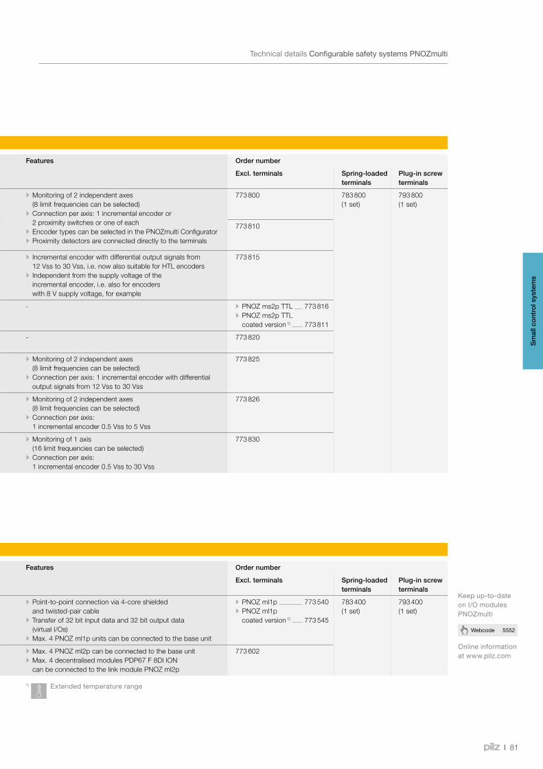
81
Webcode 5552
TechnicaldetailsConfigurablesafetysystemsPNOZmulti
PNOZmulti – Safe speed and standstill monitors
Type Connectable encoders Features Order number
Excl. terminals Spring-loaded terminals
Plug-in screw terminals
PNOZ ms1p Proximity switch, incremental encoder Sin/Cos, TTL (5 V)
• Monitoring of 2 independent axes (8 limit frequencies can be selected)
• Connection per axis: 1 incremental encoder or 2 proximity switches or one of each
• Encoder types can be selected in the PNOZmulti Configurator • Proximity detectors are connected directly to the terminals
773 800 783 800 (1 set)
793 800 (1 set)
PNOZ ms2p Proximity switch, incremental encoder Sin/Cos, TTL (5 V), HTL (24 V)
773 810
PNOZ ms2p HTL Proximity switch, incremental encoder HTL
• Incremental encoder with differential output signals from 12 Vss to 30 Vss, i.e. now also suitable for HTL encoders
• Independent from the supply voltage of the incremental encoder, i.e. also for encoders with 8 V supply voltage, for example
773 815
PNOZ ms2p TTL, PNOZ ms2p TTL coated version 1)
Proximity switch, incremental encoder Sin/Cos, TTL (5 V)
- • PNOZ ms2p TTL 773 816 • PNOZ ms2p TTL coated version 1) 773 811
PNOZ ms3p Incremental encoder Sin/Cos, TTL (5 V), HTL (24 V)
- 773 820
PNOZ ms3p HTL Incremental encoder HTL (24 V) • Monitoring of 2 independent axes (8 limit frequencies can be selected)
• Connection per axis: 1 incremental encoder with differential output signals from 12 Vss to 30 Vss
773 825
PNOZ ms3p TTL Incremental encoder Sin/Cos, TTL (5 V)
• Monitoring of 2 independent axes (8 limit frequencies can be selected)
• Connection per axis: 1 incremental encoder 0.5 Vss to 5 Vss
773 826
PNOZ ms4p Incremental encoder Sin/Cos, TTL (5 V), HTL (24 V)
• Monitoring of 1 axis (16 limit frequencies can be selected)
• Connection per axis: 1 incremental encoder 0.5 Vss to 30 Vss
773 830
PNOZmulti – Link modules
Type Application area Features Order number
Excl. terminals Spring-loaded terminals
Plug-in screw terminals
PNOZ ml1p,PNOZ ml1p coated version
To safely connect two PNOZmulti base units; tree or ring structure possible
• Point-to-point connection via 4-core shielded and twisted-pair cable
• Transfer of 32 bit input data and 32 bit output data (virtual I/Os)
• Max. 4 PNOZ ml1p units can be connected to the base unit
• PNOZ ml1p 773 540 • PNOZ ml1p coated version 1) 773 545
783 400 (1 set)
793 400 (1 set)
PNOZ ml2p To safely connect a base unit to up to 4 decentralised modules PDP
• Max. 4 PNOZ ml2p can be connected to the base unit • Max. 4 decentralised modules PDP67 F 8DI ION can be connected to the link module PNOZ ml2p
773 602
1) Extendedtemperaturerange
Onlineinformationatwww.pilz.com
Keepup-to-dateonI/OmodulesPNOZmulti
Sm
all c
ontr
ol s
yste
ms
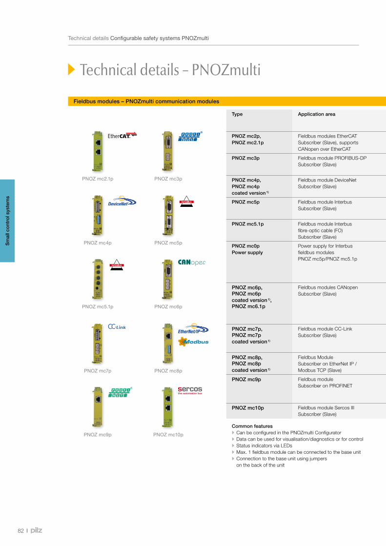
PNOZ mc4p
PNOZ mc3pPNOZ mc2.1p
PNOZ mc5.1p
PNOZ mc7p
PNOZ mc9p
PNOZ mc5p
PNOZ mc6p
PNOZ mc8p
PNOZ mc10p
82
TechnicaldetailsConfigurablesafetysystemsPNOZmulti
Technical details – PNOZmulti
Fieldbus modules – PNOZmulti communication modules
Type Application area Dimensions (H x W x D) in mm
Features Order number
PNOZ mc2p,PNOZ mc2.1p
Fieldbus modules EtherCATSubscriber (Slave), supports CANopen over EtherCAT
94 x 22.5 x 114 • Transmission rate: Max. 100 MBit/s • Connection to fieldbus via RJ45 connector
• PNOZ mc2p 773 710 • PNOZ mc2.1p 773 713
PNOZ mc3p Fieldbus module PROFIBUS-DPSubscriber (Slave)
94 x 22.5 x 119 • Station addresses from 0 ... 99, selected via rotary switch • Transmission rate: Max. 12 MBit/s • Connection: Female 9-pin D-Sub connector
773 732
PNOZ mc4p,PNOZ mc4p coated version 1)
Fieldbus module DeviceNetSubscriber (Slave)
94 x 22.5 x 122 • Station addresses from 0 … 63, selected via DIP switch • Transmission rate: 125, 250, 500 kBit/s • Connection to fieldbus via 5-pin Combicon plug-in connector
• PNOZ mc4p 773 711 • PNOZ mc4p coated version 1) 773 729
PNOZ mc5p Fieldbus module InterbusSubscriber (Slave)
94 x 22.5 x 119 • Transmission rate: 500 kBit/s, 2 MBit/s, selected via jumper • Connection to IBS IN via male 9-pin D-Sub connector, to IBS OUT via female 9-pin D-Sub connector
773 723
PNOZ mc5.1p Fieldbus module Interbus fibre-optic cable (FO)Subscriber (Slave)
94 x 22.5 x 121 • Transmission rate: 500 kBit/s, 2 MBit/s, selected via jumper • Status indicators for communication with Interbus and for errors • Connection to fieldbus via F-SMA connector
773 728
PNOZ mc0p Power supply
Power supply for Interbus fieldbus modules PNOZ mc5p/PNOZ mc5.1p
94 x 22.5 x 121 • Interface to connect the base unit and a fieldbus module • Galvanic isolation • Status indicators • Plug-in terminals (either with cage clamp terminals or screw connection)
• PNOZ mc0p Power supply 773 720
• Spring-loaded terminals (1 set) 783 400
• Plug-in screw terminals (1 set) 793 400
PNOZ mc6p,PNOZ mc6p coated version 1),PNOZ mc6.1p
Fieldbus modules CANopenSubscriber (Slave)
94 x 22.5 x 119 • Station addresses from 0 ... 99, selected via rotary switch • Transmission rate: max. 1 MBit/s, selected via rotary switch • Supported protocols:
- PNOZ mc6p: CiA DS-301 V3.0 - PNOZ mc6.1p: CiA DS-301 V4.0.2
• Connection to fieldbus via male 9-pin D-Sub connector
• PNOZ mc6p 773 712 • PNOZ mc6p coated version 1) 773 727
• PNOZ mc6.1p 773 733
PNOZ mc7p,PNOZ mc7p coated version 1)
Fieldbus module CC-LinkSubscriber (Slave)
94 x 22.5 x 122 • Station addresses from 0 ... 63, selected via rotary switch • Occupied stations: 2 • Transmission rate: max. 10 MBit/s, selected via rotary switch • Connection: 5-pin Combicon plug-in connector
• PNOZ mc7p 773 726 • PNOZ mc7p coated version 1) 773 725
PNOZ mc8p,PNOZ mc8p coated version 1)
Fieldbus Module Subscriber on EtherNet IP / Modbus TCP (Slave)
94 x 22.5 x 114 • Transmission rate: Max. 10 MBit/s • IP address is set via DIP switches on the front of the unit • Connection to fieldbus via RJ45 connector
• PNOZ mc8p 773 730 • PNOZ mc8p coated version 1) 773 734
PNOZ mc9p Fieldbus module Subscriber on PROFINET
94 x 22.5 x 114 • Device name can be configured in the PNOZmulti Configurator • Diagnostics and alarm function are not supported • Transmission rate: 100 MBit/s • Connection to fieldbus via RJ45 connector
773 731
PNOZ mc10p Fieldbus module Sercos III Subscriber (Slave)
94 x 22.5 x 114 • Transmission rate: Max. 100 MBit/s • Connection to fieldbus via RJ45 connector
773 715
Common features • Can be configured in the PNOZmulti Configurator • Data can be used for visualisation/diagnostics or for control • Status indicators via LEDs • Max. 1 fieldbus module can be connected to the base unit • Connection to the base unit using jumpers on the back of the unit
1) Extendedtemperaturerange
Sm
all c
ontr
ol s
yste
ms
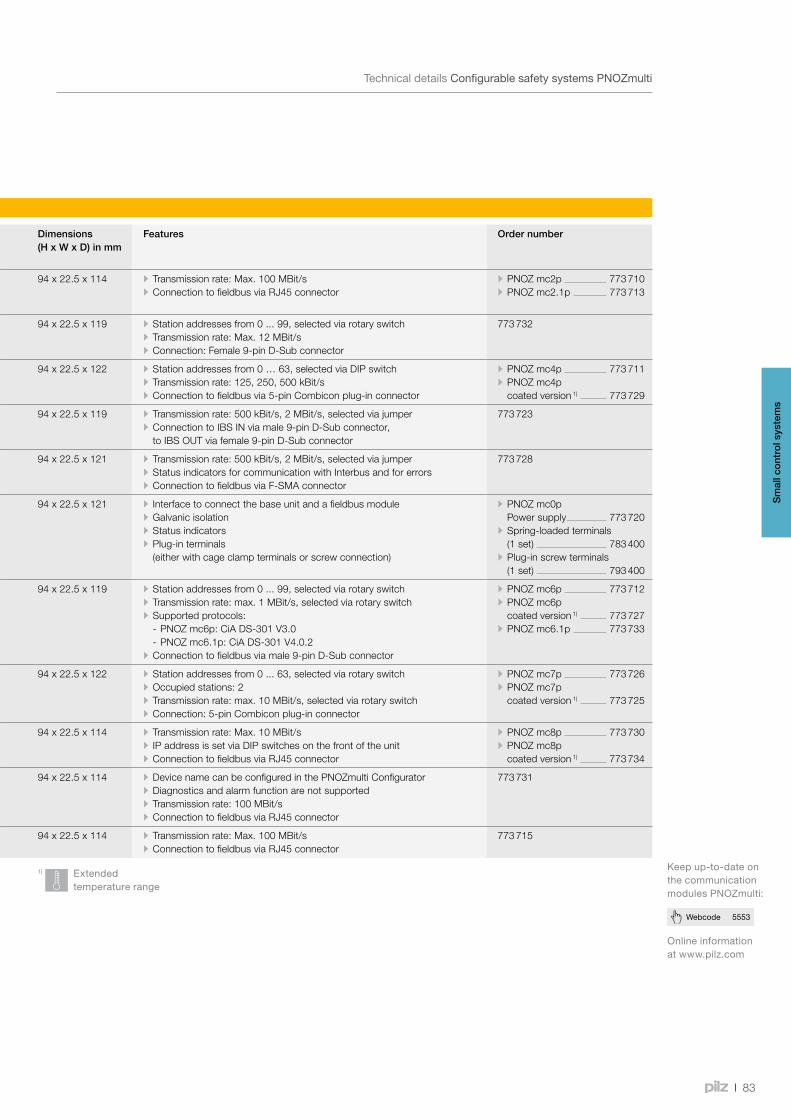
83
Webcode 5553
TechnicaldetailsConfigurablesafetysystemsPNOZmulti
Fieldbus modules – PNOZmulti communication modules
Type Application area Dimensions (H x W x D) in mm
Features Order number
PNOZ mc2p,PNOZ mc2.1p
Fieldbus modules EtherCATSubscriber (Slave), supports CANopen over EtherCAT
94 x 22.5 x 114 • Transmission rate: Max. 100 MBit/s • Connection to fieldbus via RJ45 connector
• PNOZ mc2p 773 710 • PNOZ mc2.1p 773 713
PNOZ mc3p Fieldbus module PROFIBUS-DPSubscriber (Slave)
94 x 22.5 x 119 • Station addresses from 0 ... 99, selected via rotary switch • Transmission rate: Max. 12 MBit/s • Connection: Female 9-pin D-Sub connector
773 732
PNOZ mc4p,PNOZ mc4p coated version 1)
Fieldbus module DeviceNetSubscriber (Slave)
94 x 22.5 x 122 • Station addresses from 0 … 63, selected via DIP switch • Transmission rate: 125, 250, 500 kBit/s • Connection to fieldbus via 5-pin Combicon plug-in connector
• PNOZ mc4p 773 711 • PNOZ mc4p coated version 1) 773 729
PNOZ mc5p Fieldbus module InterbusSubscriber (Slave)
94 x 22.5 x 119 • Transmission rate: 500 kBit/s, 2 MBit/s, selected via jumper • Connection to IBS IN via male 9-pin D-Sub connector, to IBS OUT via female 9-pin D-Sub connector
773 723
PNOZ mc5.1p Fieldbus module Interbus fibre-optic cable (FO)Subscriber (Slave)
94 x 22.5 x 121 • Transmission rate: 500 kBit/s, 2 MBit/s, selected via jumper • Status indicators for communication with Interbus and for errors • Connection to fieldbus via F-SMA connector
773 728
PNOZ mc0p Power supply
Power supply for Interbus fieldbus modules PNOZ mc5p/PNOZ mc5.1p
94 x 22.5 x 121 • Interface to connect the base unit and a fieldbus module • Galvanic isolation • Status indicators • Plug-in terminals (either with cage clamp terminals or screw connection)
• PNOZ mc0p Power supply 773 720
• Spring-loaded terminals (1 set) 783 400
• Plug-in screw terminals (1 set) 793 400
PNOZ mc6p,PNOZ mc6p coated version 1),PNOZ mc6.1p
Fieldbus modules CANopenSubscriber (Slave)
94 x 22.5 x 119 • Station addresses from 0 ... 99, selected via rotary switch • Transmission rate: max. 1 MBit/s, selected via rotary switch • Supported protocols:
- PNOZ mc6p: CiA DS-301 V3.0 - PNOZ mc6.1p: CiA DS-301 V4.0.2
• Connection to fieldbus via male 9-pin D-Sub connector
• PNOZ mc6p 773 712 • PNOZ mc6p coated version 1) 773 727
• PNOZ mc6.1p 773 733
PNOZ mc7p,PNOZ mc7p coated version 1)
Fieldbus module CC-LinkSubscriber (Slave)
94 x 22.5 x 122 • Station addresses from 0 ... 63, selected via rotary switch • Occupied stations: 2 • Transmission rate: max. 10 MBit/s, selected via rotary switch • Connection: 5-pin Combicon plug-in connector
• PNOZ mc7p 773 726 • PNOZ mc7p coated version 1) 773 725
PNOZ mc8p,PNOZ mc8p coated version 1)
Fieldbus Module Subscriber on EtherNet IP / Modbus TCP (Slave)
94 x 22.5 x 114 • Transmission rate: Max. 10 MBit/s • IP address is set via DIP switches on the front of the unit • Connection to fieldbus via RJ45 connector
• PNOZ mc8p 773 730 • PNOZ mc8p coated version 1) 773 734
PNOZ mc9p Fieldbus module Subscriber on PROFINET
94 x 22.5 x 114 • Device name can be configured in the PNOZmulti Configurator • Diagnostics and alarm function are not supported • Transmission rate: 100 MBit/s • Connection to fieldbus via RJ45 connector
773 731
PNOZ mc10p Fieldbus module Sercos III Subscriber (Slave)
94 x 22.5 x 114 • Transmission rate: Max. 100 MBit/s • Connection to fieldbus via RJ45 connector
773 715
Common features • Can be configured in the PNOZmulti Configurator • Data can be used for visualisation/diagnostics or for control • Status indicators via LEDs • Max. 1 fieldbus module can be connected to the base unit • Connection to the base unit using jumpers on the back of the unit
1) Extendedtemperaturerange
Onlineinformationatwww.pilz.com
Keepup-to-dateonthecommunicationmodulesPNOZmulti:
Sm
all c
ontr
ol s
yste
ms
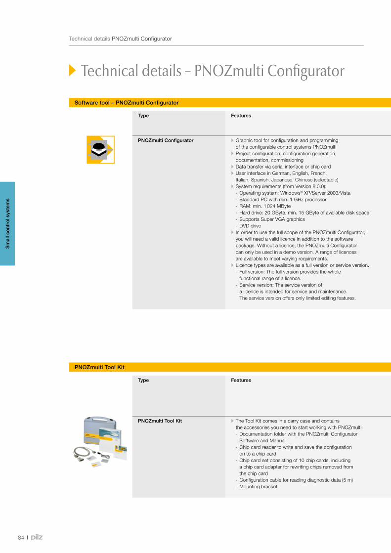
84
TechnicaldetailsPNOZmultiConfigurator
Software tool – PNOZmulti Configurator
Technical details – PNOZmulti Configurator
Type Features Licence type Order number
Type Full version Service version
PNOZmulti Configurator • Graphic tool for configuration and programming of the configurable control systems PNOZmulti
• Project configuration, configuration generation, documentation, commissioning
• Data transfer via serial interface or chip card • User interface in German, English, French, Italian, Spanish, Japanese, Chinese (selectable)
• System requirements (from Version 8.0.0): - Operating system: Windows® XP/Server 2003/Vista - Standard PC with min. 1 GHz processor - RAM: min. 1 024 MByte - Hard drive: 20 GByte, min. 15 GByte of available disk space - Supports Super VGA graphics - DVD drive
• In order to use the full scope of the PNOZmulti Configurator, you will need a valid licence in addition to the software package. Without a licence, the PNOZmulti Configurator can only be used in a demo version. A range of licences are available to meet varying requirements.
• Licence types are available as a full version or service version. - Full version: The full version provides the whole functional range of a licence.
- Service version: The service version of a licence is intended for service and maintenance. The service version offers only limited editing features.
• Basic Licence: Single user licence, issued to one owner (company name and location/project must be stated)
• User Licence: Discounted licence for an additional workstation, issued to the owner of a basic licence
• Lite Licence: Licence limited to the base units PNOZ m0p and the base units PNOZmulti Mini, for use on one workstation
• Multi User Licence: Multi user licence, graduated according to the number of workstations (up to 25, 50, 100 and over 100)
• Project Licence: Licence to use the software within a contractually limited framework
• Basic/User/Multi User/Project Upgrade Licence: Discounted licence enabling owners of a licence to change to a newer version of the software
• Time Limited Licence: Basic licence restricted to 2, 3 or 4 months
• DVD and documentation folder 1) 773 000D
• DVD 1) 773 000D
• Basic Licence • User Licence • Lite Licence • Multi User Licence • Project Licence • Time Limited Licence, 2 months • Time Limited Licence, 3 months • Time Limited Licence, 4 months
Upgrade • Basic Upgrade Licence • User Upgrade Licence • Multi User Upgrade Licence • Project Upgrade Licence
773 010B773 010K773 010L773 010M773 010G773 010S773 010R773 010Q
773 010U773 010V773 010N773 010W
773 011B773 011K773 011L773 011M773 011G---
773 011U773 011V773 011N773 011W
1)Pleaseorderlicenceseparately;thisisrequiredinordertoactivatethesoftware;otherlicencetypesavailableonrequest
PNOZmulti Tool Kit
Type Features Order number
PNOZmultiTool Kit
Chip card reader Chip cards Configuration cable
Documentation folder with PNOZmultiConfigurator
Licence type
PNOZmulti Tool Kit • The Tool Kit comes in a carry case and contains the accessories you need to start working with PNOZmulti: - Documentation folder with the PNOZmulti Configurator Software and Manual
- Chip card reader to write and save the configuration on to a chip card
- Chip card set consisting of 10 chip cards, including a chip card adapter for rewriting chips removed from the chip card
- Configuration cable for reading diagnostic data (5 m) - Mounting bracket
779 000 779 230 2) • 8 kByte (1 piece) 779 201 2)
• 8 kByte (10 piece) 779 200 2)
• 32 kByte (1 piece) 779 211 2)
• 32 kByte (10 piece) 779 212 2)
310 300 2) 773 000
Please orderlicence separately
773 010…
seePNOZmultiConfigurator
2)Foruseonlywithsubsequentorders
Sm
all c
ontr
ol s
yste
ms

85
Webcode 8633
TechnicaldetailsPNOZmultiConfigurator
Software tool – PNOZmulti Configurator
Type Features Licence type Order number
Type Full version Service version
PNOZmulti Configurator • Graphic tool for configuration and programming of the configurable control systems PNOZmulti
• Project configuration, configuration generation, documentation, commissioning
• Data transfer via serial interface or chip card • User interface in German, English, French, Italian, Spanish, Japanese, Chinese (selectable)
• System requirements (from Version 8.0.0): - Operating system: Windows® XP/Server 2003/Vista - Standard PC with min. 1 GHz processor - RAM: min. 1 024 MByte - Hard drive: 20 GByte, min. 15 GByte of available disk space - Supports Super VGA graphics - DVD drive
• In order to use the full scope of the PNOZmulti Configurator, you will need a valid licence in addition to the software package. Without a licence, the PNOZmulti Configurator can only be used in a demo version. A range of licences are available to meet varying requirements.
• Licence types are available as a full version or service version. - Full version: The full version provides the whole functional range of a licence.
- Service version: The service version of a licence is intended for service and maintenance. The service version offers only limited editing features.
• Basic Licence: Single user licence, issued to one owner (company name and location/project must be stated)
• User Licence: Discounted licence for an additional workstation, issued to the owner of a basic licence
• Lite Licence: Licence limited to the base units PNOZ m0p and the base units PNOZmulti Mini, for use on one workstation
• Multi User Licence: Multi user licence, graduated according to the number of workstations (up to 25, 50, 100 and over 100)
• Project Licence: Licence to use the software within a contractually limited framework
• Basic/User/Multi User/Project Upgrade Licence: Discounted licence enabling owners of a licence to change to a newer version of the software
• Time Limited Licence: Basic licence restricted to 2, 3 or 4 months
• DVD and documentation folder 1) 773 000D
• DVD 1) 773 000D
• Basic Licence • User Licence • Lite Licence • Multi User Licence • Project Licence • Time Limited Licence, 2 months • Time Limited Licence, 3 months • Time Limited Licence, 4 months
Upgrade • Basic Upgrade Licence • User Upgrade Licence • Multi User Upgrade Licence • Project Upgrade Licence
773 010B773 010K773 010L773 010M773 010G773 010S773 010R773 010Q
773 010U773 010V773 010N773 010W
773 011B773 011K773 011L773 011M773 011G---
773 011U773 011V773 011N773 011W
1)Pleaseorderlicenceseparately;thisisrequiredinordertoactivatethesoftware;otherlicencetypesavailableonrequest
Onlineinformationatwww.pilz.com
Keepup-to-dateonthesoftwaretoolPNOZmultiConfigurator:
PNOZmulti Tool Kit
Type Features Order number
PNOZmultiTool Kit
Chip card reader Chip cards Configuration cable
Documentation folder with PNOZmultiConfigurator
Licence type
PNOZmulti Tool Kit • The Tool Kit comes in a carry case and contains the accessories you need to start working with PNOZmulti: - Documentation folder with the PNOZmulti Configurator Software and Manual
- Chip card reader to write and save the configuration on to a chip card
- Chip card set consisting of 10 chip cards, including a chip card adapter for rewriting chips removed from the chip card
- Configuration cable for reading diagnostic data (5 m) - Mounting bracket
779 000 779 230 2) • 8 kByte (1 piece) 779 201 2)
• 8 kByte (10 piece) 779 200 2)
• 32 kByte (1 piece) 779 211 2)
• 32 kByte (10 piece) 779 212 2)
310 300 2) 773 000
Please orderlicence separately
773 010…
seePNOZmultiConfigurator
2)Foruseonlywithsubsequentorders
Sm
all c
ontr
ol s
yste
ms
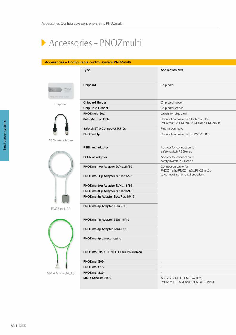
PNOZ msi1AP
PSENmaadapter
Chipcard
MMAMINI-IO-CAB
86
AccessoriesConfigurablecontrolsystemsPNOZmulti
Accessories – Configurable control system PNOZmulti
Accessories – PNOZmulti
Type Application area Features Order number
Spring-loaded terminals
Plug-in screw terminals
Chipcard Chip card - • 8 kByte, 1 piece 779 201 • 8 kByte, 10 pieces 779 200 • 32 kByte, 1 piece 779 211 • 32 kByte, 10 pieces 779212
- -
Chipcard Holder Chip card holder - 779 240 - -
Chip Card Reader Chip card reader - 779 230 - -
PNOZmulti Seal Labels for chip card 12 pieces 779 250 - -
SafetyNET p Cable Connection cable for all link modules PNOZmulti 2, PNOZmulti Mini and PNOZmulti
1 … 500 m 380 000 - -
SafetyNET p Connector RJ45s Plug-in connector - 380 400 - -
PNOZ mli1p Connection cable for the PNOZ ml1p • Ready-made as spring-loaded or screw terminal type
• Shielded
- • 5 m 773 893 • 10 m 773 894 • 50 m 773 895
• 5 m 773 890 • 10 m 773 891 • 50 m 773 892
PSEN ma adapter Adapter for connection to safety switch PSENmag
- 380 300 - -
PSEN cs adapter Adapter for connection to safety switch PSENcode
- 380 301 - -
PNOZ msi1Ap Adapter Si/Ha 25/25 Connection cable for PNOZ ms1p/PNOZ ms2p/PNOZ ms3p to connect incremental encoders
• Used to connect an incremental encoder to the speed monitors PNOZ ms1p/PNOZ ms2p/PNOZ ms3p
• Connection cable for all common makes of drive
• Connection to drive and incremental encoder via 25-pin or 15-pin D-Sub male and female connector, or wired with stranded cable
• 2.5 m 773 840 • 5 m 773 844
- -
PNOZ msi1Bp Adapter Si/Ha 25/25 • 2.5 m 773 841 • 5 m 773 839
- -
PNOZ msi3Ap Adapter Si/Ha 15/15 • 2.5 m 773 842 - -
PNOZ msi3Bp Adapter Si/Ha 15/15 • 2.5 m 773 843 - -
PNOZ msi5p Adapter Bos/Rex 15/15 • 2.5 m 773 857 • 1.5 m 773 858
- -
PNOZ msi6p Adapter Elau 9/9 • 7.5 m 773 859 • 2.5 m 773 860 • 1.5 m 773 861
- -
PNOZ msi7p Adapter SEW 15/15 • 2.5 m 773 864 • 1.5 m 773 865
- -
PNOZ msi8p Adapter Lenze 9/9 • 2.5 m 773 862 • 1.5 m 773 863
- -
PNOZ msi9p adapter cable • 5.0 m 773 856 • 2.5 m 773 854 • 1.5 m 773 855
- -
PNOZ msi19p ADAPTER ELAU PACDrive3 • 2.5 m 773 847 • 1.5 m 773 846
- -
PNOZ msi S09 - 9-pin adapter, connector set 773 870 - -
PNOZ msi S15 - 15-pin adapter, connector set 773 871 - -
PNOZ msi S25 - 25-pin adapter, connector set 773 872 - -
MM A MINI-IO-CAB Adapter cable for PNOZmulti 2, PNOZ m EF 1MM and PNOZ m EF 2MM
• Shielded • One-side pre-assembled with 8-pin Mini-IO connector
• 1.5 m 772 200 • 2.5 m 772 201 • 5.0 m 772 202
Sm
all c
ontr
ol s
yste
ms
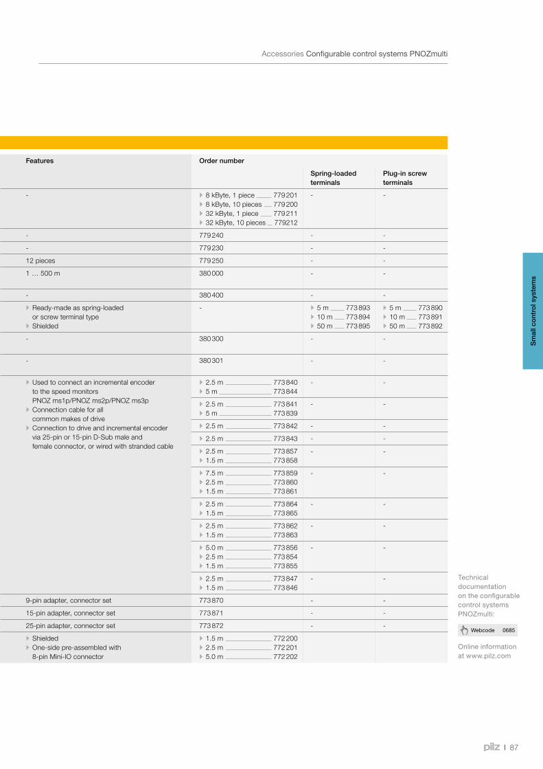
87
Webcode 0685
AccessoriesConfigurablecontrolsystemsPNOZmulti
Accessories – Configurable control system PNOZmulti
Type Application area Features Order number
Spring-loaded terminals
Plug-in screw terminals
Chipcard Chip card - • 8 kByte, 1 piece 779 201 • 8 kByte, 10 pieces 779 200 • 32 kByte, 1 piece 779 211 • 32 kByte, 10 pieces 779212
- -
Chipcard Holder Chip card holder - 779 240 - -
Chip Card Reader Chip card reader - 779 230 - -
PNOZmulti Seal Labels for chip card 12 pieces 779 250 - -
SafetyNET p Cable Connection cable for all link modules PNOZmulti 2, PNOZmulti Mini and PNOZmulti
1 … 500 m 380 000 - -
SafetyNET p Connector RJ45s Plug-in connector - 380 400 - -
PNOZ mli1p Connection cable for the PNOZ ml1p • Ready-made as spring-loaded or screw terminal type
• Shielded
- • 5 m 773 893 • 10 m 773 894 • 50 m 773 895
• 5 m 773 890 • 10 m 773 891 • 50 m 773 892
PSEN ma adapter Adapter for connection to safety switch PSENmag
- 380 300 - -
PSEN cs adapter Adapter for connection to safety switch PSENcode
- 380 301 - -
PNOZ msi1Ap Adapter Si/Ha 25/25 Connection cable for PNOZ ms1p/PNOZ ms2p/PNOZ ms3p to connect incremental encoders
• Used to connect an incremental encoder to the speed monitors PNOZ ms1p/PNOZ ms2p/PNOZ ms3p
• Connection cable for all common makes of drive
• Connection to drive and incremental encoder via 25-pin or 15-pin D-Sub male and female connector, or wired with stranded cable
• 2.5 m 773 840 • 5 m 773 844
- -
PNOZ msi1Bp Adapter Si/Ha 25/25 • 2.5 m 773 841 • 5 m 773 839
- -
PNOZ msi3Ap Adapter Si/Ha 15/15 • 2.5 m 773 842 - -
PNOZ msi3Bp Adapter Si/Ha 15/15 • 2.5 m 773 843 - -
PNOZ msi5p Adapter Bos/Rex 15/15 • 2.5 m 773 857 • 1.5 m 773 858
- -
PNOZ msi6p Adapter Elau 9/9 • 7.5 m 773 859 • 2.5 m 773 860 • 1.5 m 773 861
- -
PNOZ msi7p Adapter SEW 15/15 • 2.5 m 773 864 • 1.5 m 773 865
- -
PNOZ msi8p Adapter Lenze 9/9 • 2.5 m 773 862 • 1.5 m 773 863
- -
PNOZ msi9p adapter cable • 5.0 m 773 856 • 2.5 m 773 854 • 1.5 m 773 855
- -
PNOZ msi19p ADAPTER ELAU PACDrive3 • 2.5 m 773 847 • 1.5 m 773 846
- -
PNOZ msi S09 - 9-pin adapter, connector set 773 870 - -
PNOZ msi S15 - 15-pin adapter, connector set 773 871 - -
PNOZ msi S25 - 25-pin adapter, connector set 773 872 - -
MM A MINI-IO-CAB Adapter cable for PNOZmulti 2, PNOZ m EF 1MM and PNOZ m EF 2MM
• Shielded • One-side pre-assembled with 8-pin Mini-IO connector
• 1.5 m 772 200 • 2.5 m 772 201 • 5.0 m 772 202
Onlineinformationatwww.pilz.com
TechnicaldocumentationontheconfigurablecontrolsystemsPNOZmulti:
Sm
all c
ontr
ol s
yste
ms
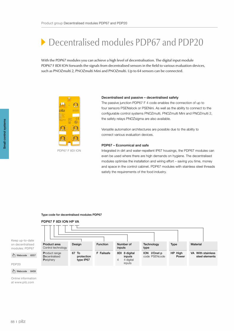
PDP67F8DIION
88
Webcode 8459
Webcode 6557
ProductgroupDecentralisedmodulesPDP67andPDP20
Decentralised modules PDP67 and PDP20
PDP67 F 8DI ION HP VA
Type code for decentralised modules PDP67
Product areaControl technology
Design Function Number of inputs
Technology type
Type Material
Product rangeDecentralisedPeriphery
67 To protection type IP67
F Failsafe 8DI
4
8 digital inputs4 digital inputs
IONcode
I/Onet pPSENcode
HP High Power
VA With stainless steel elements
Decentralised and passive – decentralised safety
The passive junction PDP67 F 4 code enables the connection of up to
four sensors PSENslock or PSENini. As well as the ability to connect to the
configurable control systems PNOZmulti, PNOZmulti Mini and PNOZmulti 2,
the safety relays PNOZsigma are also available.
Versatile automation architectures are possible due to the ability to
connect various evaluation devices.
PDP67 – Economical and safe
Integrated in dirt and water-repellent IP67 housings, the PDP67 modules can
even be used where there are high demands on hygiene. The decentralised
modules optimise the installation and wiring effort – saving you time, money
and space in the control cabinet. PDP67 modules with stainless steel threads
satisfy the requirements of the food industry.
PDP20
Onlineinformationatwww.pilz.com
With the PDP67 modules you can achieve a high level of decentralisation. The digital input module PDP67 F 8DI ION forwards the signals from decentralised sensors in the field to various evaluation devices, such as PNOZmulti 2, PNOZmulti Mini and PNOZmulti. Up to 64 sensors can be connected.
Keepup-to-dateondecentralisedmodules:PDP67
Sm
all c
ontr
ol s
yste
ms
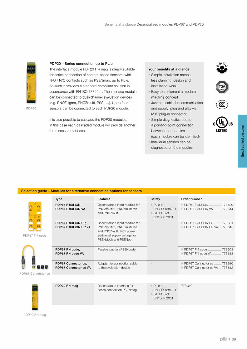
PDP20
PDP67F4code
PDP67Connectorcs
PDP20F4mag
89
Your benefits at a glance
•Simple installation means
less planning, design and
installation work
•Easy to implement a modular
machine concept
•Just one cable for communication
and supply, plug and play via
M12 plug-in connector
•Simple diagnostics due to
a point-to-point connection
between the modules
(each module can be identified)
•Individual sensors can be
diagnosed on the modules
BenefitsataglanceDecentralisedmodulesPDP67andPDP20
Decentralised modules PDP67 and PDP20
PDP20 – Series connection up to PL e
The interface module PDP20 F 4 mag is ideally suitable
for series connection of contact-based sensors, with
N/O / N/O contacts such as PSENmag, up to PL e.
As such it provides a standard-compliant solution in
accordance with EN ISO 13849-1. The interface module
can be connected to dual-channel evaluation devices
(e.g. PNOZsigma, PNOZmulti, PSS, …). Up to four
sensors can be connected to each PDP20 module.
It is also possible to cascade the PDP20 modules.
In this case each cascaded module will provide another
three sensor interfaces.
Selection guide – Modules for alternative connection options for sensors
Type Features Safety Order number
PDP67 F 8DI ION, PDP67 F 8DI ION VA
Decentralised input module for PNOZmulti 2, PNOZmulti Mini and PNOZmulti
• PL e of EN ISO 13849-1
• SIL CL 3 of EN/IEC 62061
• PDP67 F 8DI ION 773 600 • PDP67 F 8DI ION VA 773 614
PDP67 F 8DI ION HP, PDP67 F 8DI ION HP VA
Decentralised input module for PNOZmulti 2, PNOZmulti Mini and PNOZmulti; high power; additional supply voltage for PSENslock and PSENopt
• PDP67 F 8DI ION HP 773 601 • PDP67 F 8DI ION HP VA 773 615
PDP67 F 4 code,PDP67 F 4 code VA
Passive junction PSENcode • PDP67 F 4 code 773 603 • PDP67 F 4 code VA 773 613
PDP67 Connector cs, PDP67 Connector cs VA
Adapter for connection cable to the evaluation device
- • PDP67 Connector cs 773 610 • PDP67 Connector cs VA 773 612
PDP20 F 4 mag Decentralised interface for series connection PSENmag
• PL e of EN ISO 13849-1
• SIL CL 3 of EN/IEC 62061
773 310
Sm
all c
ontr
ol s
yste
ms
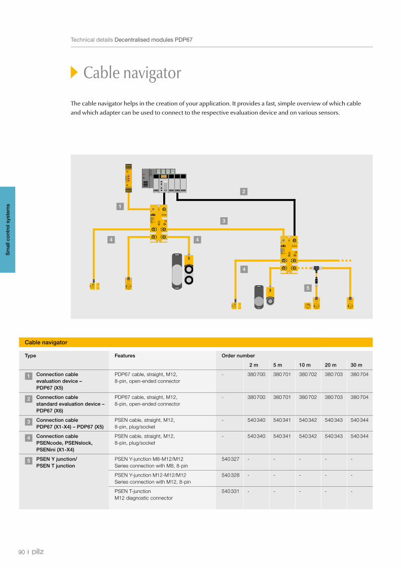
5
4
1
4 4
3
2
90
TechnicaldetailsDecentralisedmodulesPDP67
Cable navigator
The cable navigator helps in the creation of your application. It provides a fast, simple overview of which cable and which adapter can be used to connect to the respective evaluation device and on various sensors.
Cable navigator
Type Features Order number
2 m 5 m 10 m 20 m 30 m
1 Connection cable evaluation device – PDP67 (X5)
PDP67 cable, straight, M12, 8-pin, open-ended connector
- 380 700 380 701 380 702 380 703 380 704
2 Connection cable standard evaluation device – PDP67 (X6)
PDP67 cable, straight, M12, 8-pin, open-ended connector
- 380 700 380 701 380 702 380 703 380 704
3 Connection cable PDP67 (X1-X4) – PDP67 (X5)
PSEN cable, straight, M12, 8-pin, plug/socket
- 540 340 540 341 540 342 540 343 540 344
4 Connection cable PSENcode, PSENslock, PSENini (X1-X4)
PSEN cable, straight, M12, 8-pin, plug/socket
- 540 340 540 341 540 342 540 343 540 344
5 PSEN Y junction/ PSEN T junction
PSEN Y-junction M8-M12/M12 Series connection with M8, 8-pin
540 327 - - - - -
PSEN Y-junction M12-M12/M12 Series connection with M12, 8-pin
540 328 - - - - -
PSEN T-junction M12 diagnostic connector
540 331 - - - - -
Sm
all c
ontr
ol s
yste
ms
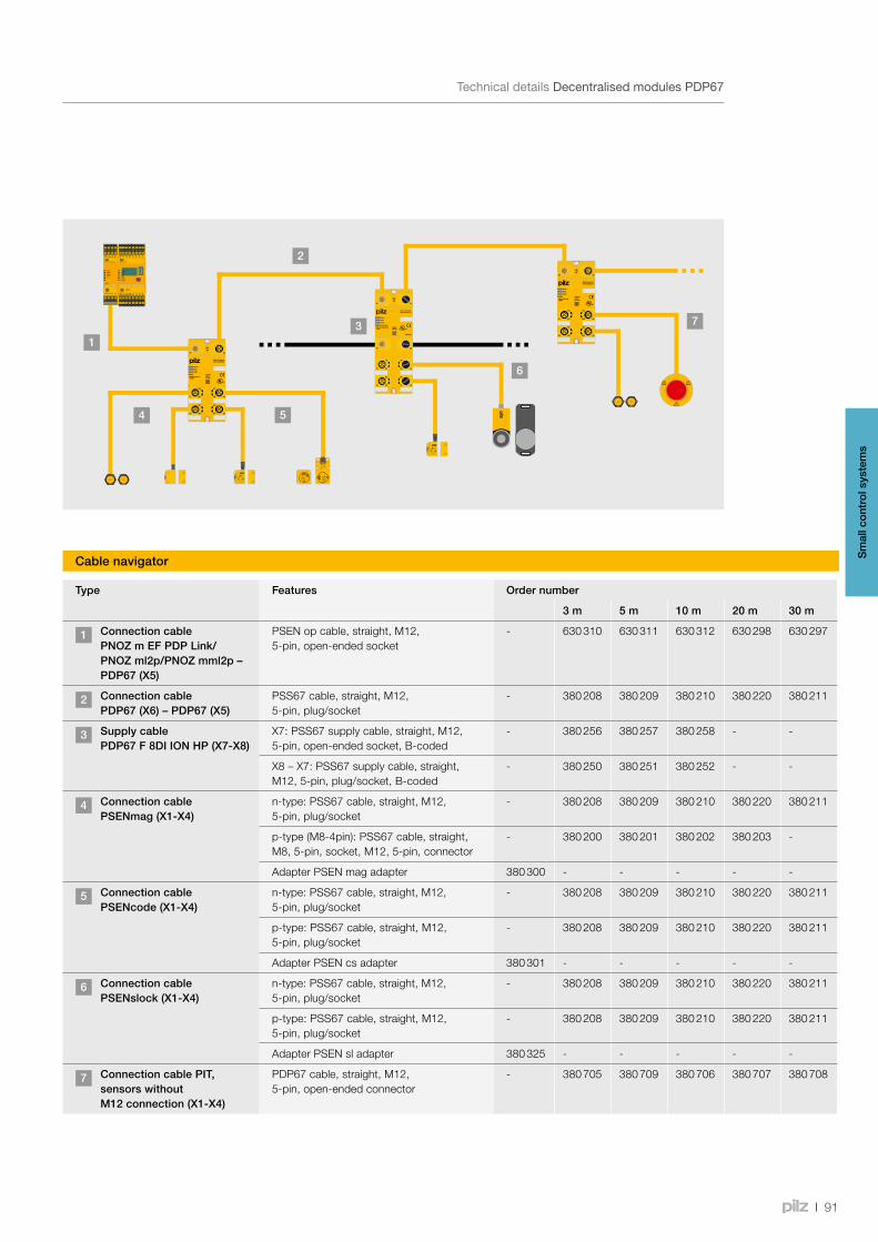
1
2
54
6
3 7
91
TechnicaldetailsDecentralisedmodulesPDP67
Cable navigator
Type Features Order number
3 m 5 m 10 m 20 m 30 m
1 Connection cable PNOZ m EF PDP Link/PNOZ ml2p/PNOZ mml2p – PDP67 (X5)
PSEN op cable, straight, M12, 5-pin, open-ended socket
- 630 310 630 311 630 312 630 298 630 297
2 Connection cable PDP67 (X6) – PDP67 (X5)
PSS67 cable, straight, M12, 5-pin, plug/socket
- 380 208 380 209 380 210 380 220 380 211
3 Supply cable PDP67 F 8DI ION HP (X7-X8)
X7: PSS67 supply cable, straight, M12, 5-pin, open-ended socket, B-coded
- 380 256 380 257 380 258 - -
X8 – X7: PSS67 supply cable, straight, M12, 5-pin, plug/socket, B-coded
- 380 250 380 251 380 252 - -
4 Connection cablePSENmag (X1-X4)
n-type: PSS67 cable, straight, M12, 5-pin, plug/socket
- 380 208 380 209 380 210 380 220 380 211
p-type (M8-4pin): PSS67 cable, straight, M8, 5-pin, socket, M12, 5-pin, connector
- 380 200 380 201 380 202 380 203 -
Adapter PSEN mag adapter 380 300 - - - - -
5 Connection cablePSENcode (X1-X4)
n-type: PSS67 cable, straight, M12, 5-pin, plug/socket
- 380 208 380 209 380 210 380 220 380 211
p-type: PSS67 cable, straight, M12, 5-pin, plug/socket
- 380 208 380 209 380 210 380 220 380 211
Adapter PSEN cs adapter 380 301 - - - - -
6 Connection cablePSENslock (X1-X4)
n-type: PSS67 cable, straight, M12, 5-pin, plug/socket
- 380 208 380 209 380 210 380 220 380 211
p-type: PSS67 cable, straight, M12, 5-pin, plug/socket
- 380 208 380 209 380 210 380 220 380 211
Adapter PSEN sl adapter 380 325 - - - - -
7 Connection cable PIT, sensors without M12 connection (X1-X4)
PDP67 cable, straight, M12, 5-pin, open-ended connector
- 380 705 380 709 380 706 380 707 380 708
Cable navigator Sm
all c
ontr
ol s
yste
ms
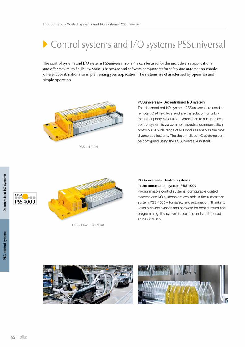
PSSuHFPN
PSSuPLC1FSSNSD
92
Control systems and I/O systems PSSuniversal
ProductgroupControlsystemsandI/OsystemsPSSuniversal
The control systems and I/O systems PSSuniversal from Pilz can be used for the most diverse applications and offer maximum flexibility. Various hardware and software components for safety and automation enable different combinations for implementing your application. The systems are characterised by openness and simple operation.
PSSuniversal – Decentralised I/O system
The decentralised I/O systems PSSuniversal are used as
remote I/O at field level and are the solution for tailor-
made periphery expansion. Connection to a higher level
control system is via common industrial communication
protocols. A wide range of I/O modules enables the most
diverse applications. The decentralised I/O systems can
be configured using the PSSuniversal Assistant.
Dec
entr
alis
ed I/
O s
yste
ms
PLC
con
trol
sys
tem
s
PSSuniversal – Control systems
in the automation system PSS 4000
Programmable control systems, configurable control
systems and I/O systems are available in the automation
system PSS 4000 – for safety and automation. Thanks to
various device classes and software for configuration and
programming, the system is scalable and can be used
across industry.
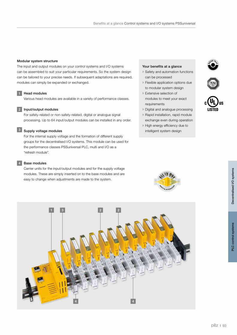
4 4
21 3 2
93
BenefitsataglanceControlsystemsandI/OsystemsPSSuniversal
Your benefits at a glance
•Safety and automation functions
can be processed
•Flexible application options due
to modular system design
•Extensive selection of
modules to meet your exact
requirements
•Digital and analogue processing
•Rapid installation, rapid module
exchange even during operation
•High energy efficiency due to
intelligent system design
Modular system structure
The input and output modules on your control systems and I/O systems
can be assembled to suit your particular requirements. So the system design
can be tailored to your precise needs. If subsequent adaptations are required,
modules can simply be expanded or exchanged.
1 Head modules
Various head modules are available in a variety of performance classes.
2 Input/output modules
For safety-related or non-safety-related, digital or analogue signal
processing. Up to 64 input/output modules can be installed in any order.
3 Supply voltage modules
For the internal supply voltage and the formation of different supply
groups for the decentralised I/O systems. This module can be used for
the performance classes PSSuniversal PLC, multi and I/O as a
“refresh module”.
4 Base modules
Carrier units for the input/output modules and for the supply voltage
modules. These are simply inserted on to the base modules and are
easy to change when adjustments are made to the system.
Dec
entr
alis
ed I/
O s
yste
ms
PLC
con
trol
sys
tem
s
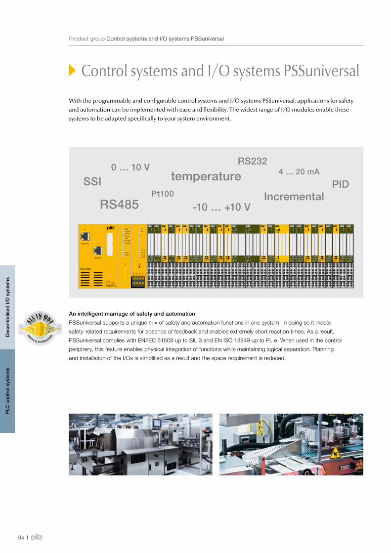
94
Control systems and I/O systems PSSuniversal
ProductgroupControlsystemsandI/OsystemsPSSuniversal
With the programmable and configurable control systems and I/O systems PSSuniversal, applications for safety and automation can be implemented with ease and flexibility. The widest range of I/O modules enable these systems to be adapted specifically to your system environment.
An intelligent marriage of safety and automation
PSSuniversal supports a unique mix of safety and automation functions in one system. In doing so it meets
safety-related requirements for absence of feedback and enables extremely short reaction times. As a result,
PSSuniversal complies with EN/IEC 61508 up to SIL 3 and EN ISO 13849 up to PL e. When used in the control
periphery, this feature enables physical integration of functions while maintaining logical separation. Planning
and installation of the I/Os is simplified as a result and the space requirement is reduced.
Dec
entr
alis
ed I/
O s
yste
ms
PLC
con
trol
sys
tem
s
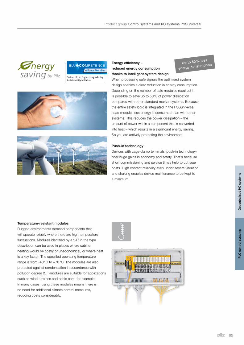
95
Control systems and I/O systems PSSuniversal
ProductgroupControlsystemsandI/OsystemsPSSuniversal
Energy efficiency –
reduced energy consumption
thanks to intelligent system design
When processing safe signals the optimised system
design enables a clear reduction in energy consumption.
Depending on the number of safe modules required it
is possible to save up to 50 % of power dissipation
compared with other standard market systems. Because
the entire safety logic is integrated in the PSSuniversal
head module, less energy is consumed than with other
systems. This reduces the power dissipation – the
amount of power within a component that is converted
into heat – which results in a significant energy saving.
So you are actively protecting the environment.
Push-in technology
Devices with cage clamp terminals (push-in technology)
offer huge gains in economy and safety. That’s because
short commissioning and service times help to cut your
costs. High contact reliability even under severe vibration
and shaking enables device maintenance to be kept to
a minimum.
Temperature-resistant modules
Rugged environments demand components that
will operate reliably where there are high temperature
fluctuations. Modules identified by a “-T” in the type
description can be used in places where cabinet
heating would be costly or uneconomical, or where heat
is a key factor. The specified operating temperature
range is from -40 °C to +70 °C. The modules are also
protected against condensation in accordance with
pollution degree 2. T-modules are suitable for applications
such as wind turbines and cable cars, for example.
In many cases, using these modules means there is
no need for additional climate control measures,
reducing costs considerably.
Up to 50 % less
energy consumption
Dec
entr
alis
ed I/
O s
yste
ms
PLC
con
trol
sys
tem
s
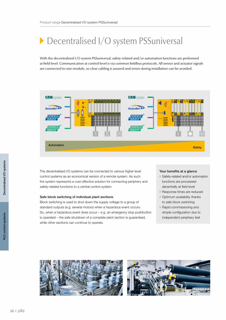
96
Decentralised I/O system PSSuniversal
ProductrangeDecentralisedI/OsystemPSSuniversal
With the decentralised I/O system PSSuniversal, safety-related and/or automation functions are performed at field level. Communication at control level is via common fieldbus protocols. All sensor and actuator signals are connected to one module, so clear cabling is assured and errors during installation can be avoided.
AutomationSafety
Your benefits at a glance
•Safety-related and/or automation
functions are processed
decentrally at field level
•Response times are reduced
•Optimum availability thanks
to safe block switching
•Rapid commissioning and
simple configuration due to
independent periphery test
The decentralised I/O systems can be connected to various higher level
control systems as an economical version of a remote system. As such
the system represents a cost-effective solution for connecting periphery and
safety-related functions to a central control system.
Safe block switching of individual plant sections
Block switching is used to shut down the supply voltage to a group of
standard outputs (e.g. several motors) when a hazardous event occurs.
So, when a hazardous event does occur – e.g. an emergency stop pushbutton
is operated – the safe shutdown of a complete plant section is guaranteed,
while other sections can continue to operate.
Dec
entr
alis
ed I/
O s
yste
ms
PLC
con
trol
sys
tem
s
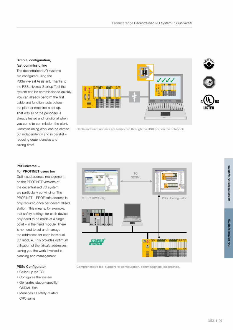
STEP7 HWConfig
TCIGDSML
PSSu Configurator
97
Simple, configuration,
fast commissioning
The decentralised I/O systems
are configured using the
PSSuniversal Assistant. Thanks to
the PSSuniversal Startup Tool the
system can be commissioned quickly.
You can already perform the first
cable and function tests before
the plant or machine is set up.
That way all of the periphery is
already tested and functional when
you come to commission the plant.
Commissioning work can be carried
out independently and in parallel –
reducing dependencies and
saving time!
CableandfunctiontestsaresimplyrunthroughtheUSBportonthenotebook.
Decentralised I/O system PSSuniversal
ProductrangeDecentralisedI/OsystemPSSuniversal
Comprehensivetoolsupportforconfiguration,commissioning,diagnostics.
PSSuniversal –
For PROFINET users too
Optimised address management
on the PROFINET versions of
the decentralised I/O system
are particularly convincing. The
PROFINET – PROFIsafe address is
only required once per decentralised
station. This means, for example,
that safety settings for each device
only need to be made at a single
point – in the head module. There
is no need to set and manage
the addresses for each individual
I/O module. This provides optimum
utilisation of the failsafe addresses,
saving you the work involved in
planning and management.
PSSu Configurator
•Called up via TCI
•Configures the system
•Generates station-specific
GSDML files
•Manages all safety-related
CRC sums
Dec
entr
alis
ed I/
O s
yste
ms
PLC
con
trol
sys
tem
s
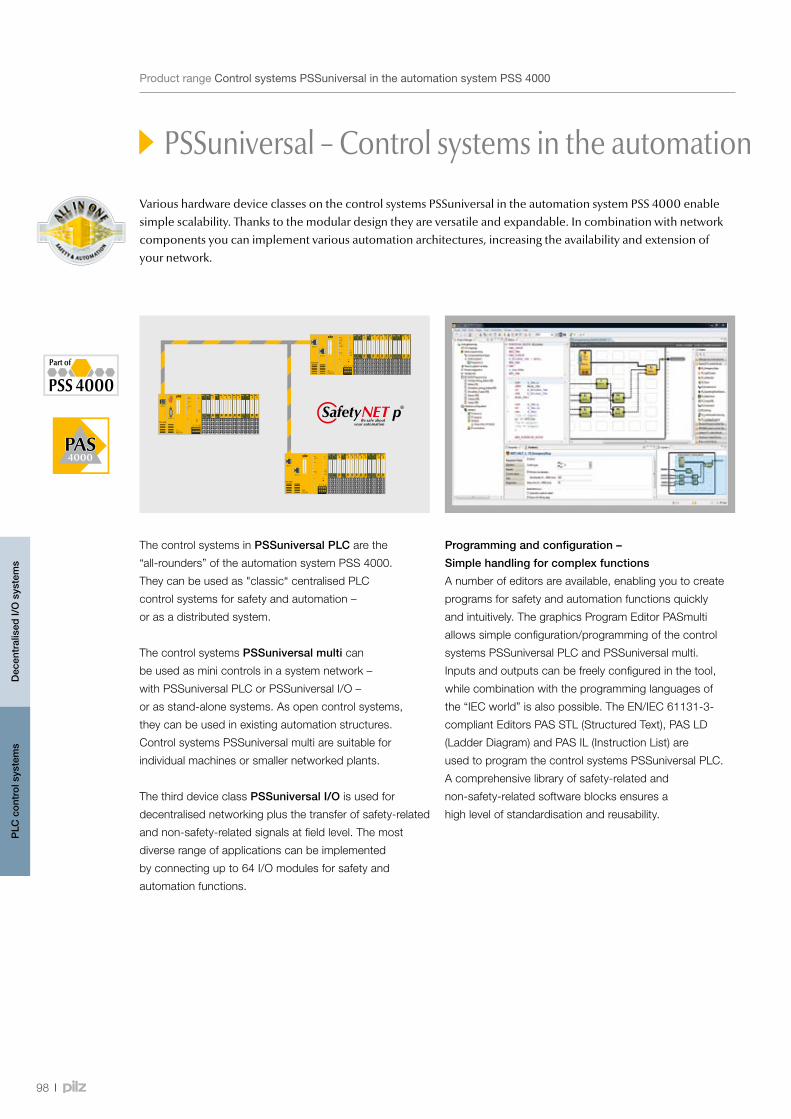
98
PSSuniversal – Control systems in the automation system PSS 4000
ProductrangeControlsystemsPSSuniversalintheautomationsystemPSS4000
Various hardware device classes on the control systems PSSuniversal in the automation system PSS 4000 enable simple scalability. Thanks to the modular design they are versatile and expandable. In combination with network components you can implement various automation architectures, increasing the availability and extension of your network.
The control systems in PSSuniversal PLC are the
“all-rounders” of the automation system PSS 4000.
They can be used as "classic“ centralised PLC
control systems for safety and automation –
or as a distributed system.
The control systems PSSuniversal multi can
be used as mini controls in a system network –
with PSSuniversal PLC or PSSuniversal I/O –
or as stand-alone systems. As open control systems,
they can be used in existing automation structures.
Control systems PSSuniversal multi are suitable for
individual machines or smaller networked plants.
The third device class PSSuniversal I/O is used for
decentralised networking plus the transfer of safety-related
and non-safety-related signals at field level. The most
diverse range of applications can be implemented
by connecting up to 64 I/O modules for safety and
automation functions.
PLC
con
trol
sys
tem
sD
ecen
tral
ised
I/O
sys
tem
s
Programming and configuration –
Simple handling for complex functions
A number of editors are available, enabling you to create
programs for safety and automation functions quickly
and intuitively. The graphics Program Editor PASmulti
allows simple configuration/programming of the control
systems PSSuniversal PLC and PSSuniversal multi.
Inputs and outputs can be freely configured in the tool,
while combination with the programming languages of
the “IEC world” is also possible. The EN/IEC 61131-3-
compliant Editors PAS STL (Structured Text), PAS LD
(Ladder Diagram) and PAS IL (Instruction List) are
used to program the control systems PSSuniversal PLC.
A comprehensive library of safety-related and
non-safety-related software blocks ensures a
high level of standardisation and reusability.

99
Webcode 5092
PSSuniversal – Control systems in the automation system PSS 4000
ProductrangeControlsystemsPSSuniversalintheautomationsystemPSS4000
Real-time-Ethernet SafetyNET p –
Pure communication
In addition to the connection to
communication networks such as
Ethernet/IP, EtherCAT, Modbus TCP
Profinet and Profibus-DP, the control
systems PSSuniversal PLC also
have a SafetyNET p communication
interface. SafetyNET p is the
backbone of the whole system.
Various infrastructure components
such as switches enable the network
to be adapted to the plant structure.
Gateways are also available to
connect to various third-party
control systems.
Professionaldiagnosticsandvisualisation.
Keepup-to-dateontheautomationsystemPSS4000:
PLC
con
trol
sys
tem
sD
ecen
tral
ised
I/O
sys
tem
s
Shorter project run times –
due to hardware-independent programming and the ability of subtasks to run in parallel.
On many automation systems, hardware must be selected for the configuration/programming process. Subsequent
modifications are very costly. With PSS 4000 it’s different: in this case the hardware selection and distribution of the
program to the hardware can take place very late in the process, as it is largely independent of the configuration stage.
Running subtasks in parallel: the hardware can be designed at the same
Reduce the overall time
for your engineering projects!time as the software is created for the control functions.
Flexible for subsequent changes: If you need to expand your application
or machine, it is no problem to add another control system. Without a great
deal of effort, the user program can then be divided over three control systems
instead of two, for example.
By running subprocesses in parallel you can reduce the overall time for your
engineering projects.
Onlineinformationatwww.pilz.com
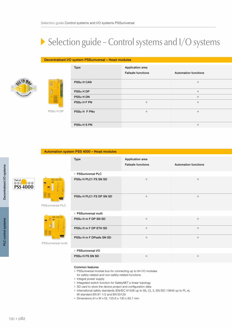
PSSu H DP
PSSuniversal multi
PSSuniversal PLC
100
Selection guide – Control systems and I/O systems PSSuniversal
SelectionguideControlsystemsandI/OsystemsPSSuniversal
Type Application area Communication interfaces Features Order number
Failsafe functions Automation functions Regular version
T-Type1)
PSSu H CAN • CANopen (Slave, CANopen Standard 4.0)
• PSSuniversal module bus for connecting up to 64 I/O modules for safety-related and non-safety-related functions
• Dimensions (H x W x D): 128.4 x 75.2 x 79.4 mm
312 047 314 047
PSSu H DP • PROFIBUS-DP (Slave) 312 045 314 045
PSSu H DN • DeviceNet (Slave) 312 046 314 046
PSSu H F PN • 1 x PROFINET • 1 x PROFIsafe
312 040 (312 043) 2)
-
PSSu H F PNo • 1 x PROFINET • 1 x PROFIsafe • Fibre-optic
312 042 -
PSSu H S PN • 2 x PROFINET 312 041 -
Decentralised I/O system PSSuniversal – Head modules
Automation system PSS 4000 – Head modules
Type Application area Communication interfaces Features Order number
Failsafe functions Automation functions Regular version
T-Type1)
• PSSuniversal PLC
PSSu H PLC1 FS SN SD • 2 x SafetyNET p • Can be configured with the graphics Program Editor PASmulti • Programming in PAS IL (Instruction List), PAS LD (Ladder Diagram) and PAS STL (Structured Text) in accordance with EN/IEC 61131-3
• Programming via Ethernet TCP/IP • Max. number of failsafe tasks: 9 • Max. number of standard tasks: 9
312 070 314 070
PSSu H PLC1 FS DP SN SD • SafetyNET p • PROFIBUS-DP (Slave, DPV0)
312 071 -
• PSSuniversal multi
PSSu H m F DP SN SD • SafetyNET p • PROFIBUS-DP (Slave, DPV0)
• Local safety functions • Can be configured with the graphics Program Editor PASmulti • Max. number of failsafe tasks: 1 • Devices with SafetyNET p interface: Max. number of SafetyNET p connections: 5
312 065 -
PSSu H m F DP ETH SD • Ethernet • PROFIBUS-DP (Slave, DPV0)
312 060 -
PSSu H m F DPsafe SN SD • SafetyNET p • PROFIBUS/PROFIsafe (PROFIsafe V2.4)
312 066 -
• PSSuniversal I/O
PSSu H FS SN SD • 2 x SafetyNET p • Communication with other SafetyNET p devices (RTFN) • Standard module bus for standard I/O modules
312 085 314 085
Common features • PSSuniversal module bus for connecting up to 64 I/O modules for safety-related and non-safety-related functions
• Integral power supply • Integrated switch function for SafetyNET p linear topology • SD card to store the device project and configuration data • International safety standards (EN/IEC 61508 up to SIL CL 3, EN ISO 13849 up to PL e), lift standard EN 81-1/2 and EN 50129
• Dimensions (H x W x D): 125.6 x 130 x 83.7 mm
1) Forincreasedenvironmentalrequirements
2)Half-byteversion
Dec
entr
alis
ed I/
O s
yste
ms
PLC
con
trol
sys
tem
s
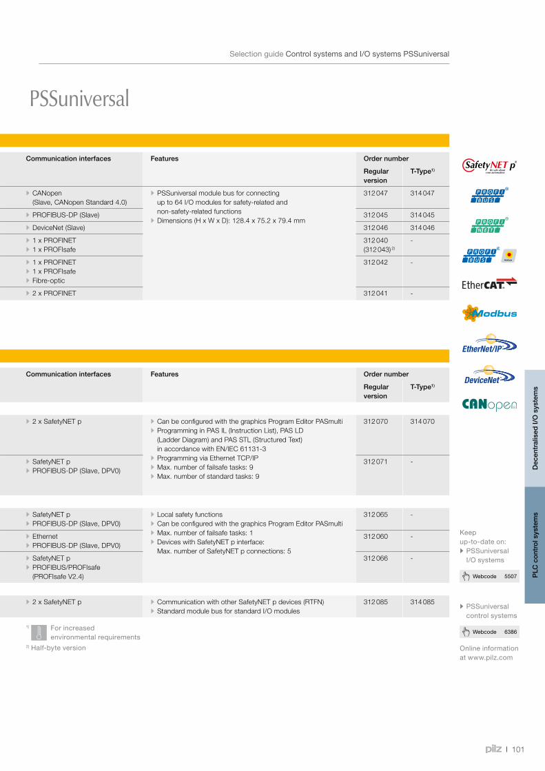
101
Webcode 6386
Webcode 5507
Selection guide – Control systems and I/O systems PSSuniversal
SelectionguideControlsystemsandI/OsystemsPSSuniversal
Type Application area Communication interfaces Features Order number
Failsafe functions Automation functions Regular version
T-Type1)
PSSu H CAN • CANopen (Slave, CANopen Standard 4.0)
• PSSuniversal module bus for connecting up to 64 I/O modules for safety-related and non-safety-related functions
• Dimensions (H x W x D): 128.4 x 75.2 x 79.4 mm
312 047 314 047
PSSu H DP • PROFIBUS-DP (Slave) 312 045 314 045
PSSu H DN • DeviceNet (Slave) 312 046 314 046
PSSu H F PN • 1 x PROFINET • 1 x PROFIsafe
312 040 (312 043) 2)
-
PSSu H F PNo • 1 x PROFINET • 1 x PROFIsafe • Fibre-optic
312 042 -
PSSu H S PN • 2 x PROFINET 312 041 -
Decentralised I/O system PSSuniversal – Head modules
Automation system PSS 4000 – Head modules
Type Application area Communication interfaces Features Order number
Failsafe functions Automation functions Regular version
T-Type1)
• PSSuniversal PLC
PSSu H PLC1 FS SN SD • 2 x SafetyNET p • Can be configured with the graphics Program Editor PASmulti • Programming in PAS IL (Instruction List), PAS LD (Ladder Diagram) and PAS STL (Structured Text) in accordance with EN/IEC 61131-3
• Programming via Ethernet TCP/IP • Max. number of failsafe tasks: 9 • Max. number of standard tasks: 9
312 070 314 070
PSSu H PLC1 FS DP SN SD • SafetyNET p • PROFIBUS-DP (Slave, DPV0)
312 071 -
• PSSuniversal multi
PSSu H m F DP SN SD • SafetyNET p • PROFIBUS-DP (Slave, DPV0)
• Local safety functions • Can be configured with the graphics Program Editor PASmulti • Max. number of failsafe tasks: 1 • Devices with SafetyNET p interface: Max. number of SafetyNET p connections: 5
312 065 -
PSSu H m F DP ETH SD • Ethernet • PROFIBUS-DP (Slave, DPV0)
312 060 -
PSSu H m F DPsafe SN SD • SafetyNET p • PROFIBUS/PROFIsafe (PROFIsafe V2.4)
312 066 -
• PSSuniversal I/O
PSSu H FS SN SD • 2 x SafetyNET p • Communication with other SafetyNET p devices (RTFN) • Standard module bus for standard I/O modules
312 085 314 085
Common features • PSSuniversal module bus for connecting up to 64 I/O modules for safety-related and non-safety-related functions
• Integral power supply • Integrated switch function for SafetyNET p linear topology • SD card to store the device project and configuration data • International safety standards (EN/IEC 61508 up to SIL CL 3, EN ISO 13849 up to PL e), lift standard EN 81-1/2 and EN 50129
• Dimensions (H x W x D): 125.6 x 130 x 83.7 mm
1) Forincreasedenvironmentalrequirements
2)Half-byteversion
Dec
entr
alis
ed I/
O s
yste
ms
PLC
con
trol
sys
tem
s
Onlineinformationatwww.pilz.com
• PSSuniversalcontrolsystems
Keepup-to-dateon:• PSSuniversalI/Osystems

PSSu E F PS
PSSu E PD
102
SelectionguideControlsystemsandI/OsystemsPSSuniversal
Type Suitable for
Function Applica-tion area
Electrical data Order number
Screw terminals 1) Cage clamp terminals 1)
PS
Sun
iver
sal –
I/O
sys
tem
PS
Sun
iver
sal –
Con
trol
sys
tem
s P
SS
400
0
Fails
afe
func
tions
Aut
om
atio
n fu
nctio
ns
Supply voltage
Current load capacity Module supply
Current load capacity Periphery supply
Ord
er
num
ber
PS
Su
BP
1/8
S 2)
31
2 60
0
PS
Su
BP
-C 1
/8 S
3)
31
2 61
0
PS
Su
BP
1/1
2 S
31
2 61
8
PS
Su
BP
-C1
1/12
S
312
618
PS
Su
BP
-C 1
/12
S
31
2 62
2
PS
Su
BP
2/1
6 S
31
2 62
8
PS
Su
BP
-C 2
/16
S
31
2 63
0
PS
Su
BS
1/8
S
31
2 65
0
PS
Su
BS
-R 1
/8 S
312
652
PS
Su
BS
-R 2
/8 S
312
654
PS
Su
BS
2/8
S
31
2 65
6
PS
Su
BP
1/8
C 2)
31
2 60
1
PS
Su
BP
-C 1
/8 C
3)
31
2 61
1
PS
Su
BP
1/1
2 C
31
2 61
9
PS
Su
BP
-C 1
/12
C
31
2 61
9
PS
Su
BP
-C1
1/12
C
312
623
PS
Su
BP
2/1
6 C
31
2 62
9
PS
Su
BP
-C 2
/16
C
31
2 63
1
PS
Su
BS
1/8
C
31
2 65
1
PS
Su
BS
-R 1
/8 C
312
653
PS
Su
BS
-R 2
/8 C
312
655
PS
Su
BS
2/8
C
31
2 65
7
Sui
tab
le
bas
e m
od
ule
PSSu E F PS Power supply 24 VDC max. 1.5 A max. 10 A 312 190 1)
PSSu E F PS1 Power supply, buffered
24 VDC max. 2.0 A max. 10 A 312 191 1)
PSSu E F PS2 Power supply, buffered
24 VDC max. 1.0 A max. 10 A 312 192 1)
PSSu E F PS-P Power supply, periphery
24 VDC - max. 10 A 312 185 1)
PSSu E PD Voltage distribution
- - - 312 195 1)
PSSu E PD1 Voltage distribution
- - - 312 196 1)
PSSu S PD-D Voltage distribution
- - - 312 197
PSSu E F BSW Block switching function
24 VDC - max. 8 A 312 230 1)
PSSu E PS-P 5 V Voltage distribution
24 VDC - - 312 590
PSSu E PS-P +/- 10 V Voltage distribution
24 VDC - - 312 591
PSSu E PS-P +/- 15 V Voltage distribution
24 VDC - - 312 592
1) ThemodulesarealsoavailableasaT-typeforenhancedenvironmentalrequirements.TheordernumbersfortheT-typemodulesare314…insteadof312…
2)WithoutC-rail3)WithC-rail
Supply modules, junction modules and safe block switching module
Selection guide – PSSuniversal
PSSu E F 4DI
Product range Design Application area Functions
PSSuniversal EK
Electronic moduleCompact module
FS
FailsafeStandard (Automation)
4 DIAI UINCPS…
4 digital inputsAnalogue input voltageIncremental encoderPower supplyFurther functions
Type code for PSSuniversal electronic module/supply modules
Dec
entr
alis
ed I/
O s
yste
ms
PLC
con
trol
sys
tem
s
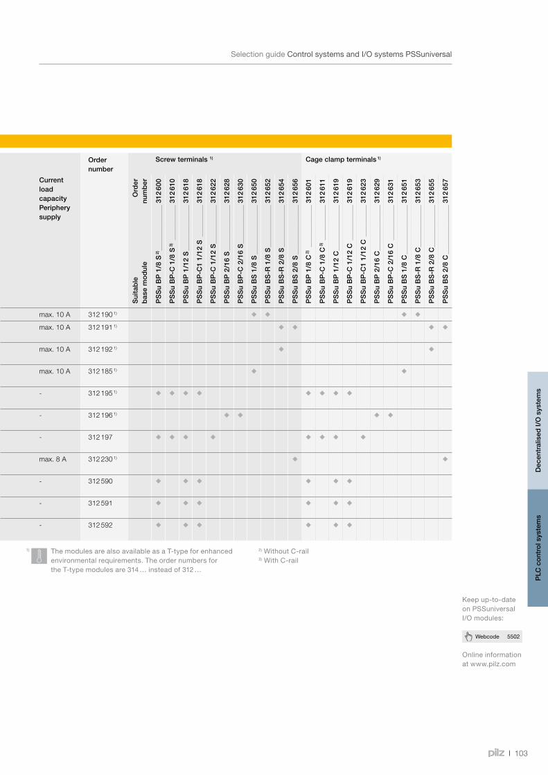
103
Webcode 5502
SelectionguideControlsystemsandI/OsystemsPSSuniversal
Type Suitable for
Function Applica-tion area
Electrical data Order number
Screw terminals 1) Cage clamp terminals 1)
PS
Sun
iver
sal –
I/O
sys
tem
PS
Sun
iver
sal –
Con
trol
sys
tem
s P
SS
400
0
Fails
afe
func
tions
Aut
om
atio
n fu
nctio
ns
Supply voltage
Current load capacity Module supply
Current load capacity Periphery supply
Ord
er
num
ber
PS
Su
BP
1/8
S 2)
31
2 60
0
PS
Su
BP
-C 1
/8 S
3)
31
2 61
0
PS
Su
BP
1/1
2 S
31
2 61
8
PS
Su
BP
-C1
1/12
S
312
618
PS
Su
BP
-C 1
/12
S
31
2 62
2
PS
Su
BP
2/1
6 S
31
2 62
8
PS
Su
BP
-C 2
/16
S
31
2 63
0
PS
Su
BS
1/8
S
31
2 65
0
PS
Su
BS
-R 1
/8 S
312
652
PS
Su
BS
-R 2
/8 S
312
654
PS
Su
BS
2/8
S
31
2 65
6
PS
Su
BP
1/8
C 2)
31
2 60
1
PS
Su
BP
-C 1
/8 C
3)
31
2 61
1
PS
Su
BP
1/1
2 C
31
2 61
9
PS
Su
BP
-C 1
/12
C
31
2 61
9
PS
Su
BP
-C1
1/12
C
312
623
PS
Su
BP
2/1
6 C
31
2 62
9
PS
Su
BP
-C 2
/16
C
31
2 63
1
PS
Su
BS
1/8
C
31
2 65
1
PS
Su
BS
-R 1
/8 C
312
653
PS
Su
BS
-R 2
/8 C
312
655
PS
Su
BS
2/8
C
31
2 65
7
Sui
tab
le
bas
e m
od
ule
PSSu E F PS Power supply 24 VDC max. 1.5 A max. 10 A 312 190 1)
PSSu E F PS1 Power supply, buffered
24 VDC max. 2.0 A max. 10 A 312 191 1)
PSSu E F PS2 Power supply, buffered
24 VDC max. 1.0 A max. 10 A 312 192 1)
PSSu E F PS-P Power supply, periphery
24 VDC - max. 10 A 312 185 1)
PSSu E PD Voltage distribution
- - - 312 195 1)
PSSu E PD1 Voltage distribution
- - - 312 196 1)
PSSu S PD-D Voltage distribution
- - - 312 197
PSSu E F BSW Block switching function
24 VDC - max. 8 A 312 230 1)
PSSu E PS-P 5 V Voltage distribution
24 VDC - - 312 590
PSSu E PS-P +/- 10 V Voltage distribution
24 VDC - - 312 591
PSSu E PS-P +/- 15 V Voltage distribution
24 VDC - - 312 592
1) ThemodulesarealsoavailableasaT-typeforenhancedenvironmentalrequirements.TheordernumbersfortheT-typemodulesare314…insteadof312…
2)WithoutC-rail3)WithC-rail
Supply modules, junction modules and safe block switching module
Selection guide – PSSuniversal
Onlineinformationatwww.pilz.com
Keepup-to-dateonPSSuniversalI/Omodules:
Dec
entr
alis
ed I/
O s
yste
ms
PLC
con
trol
sys
tem
s
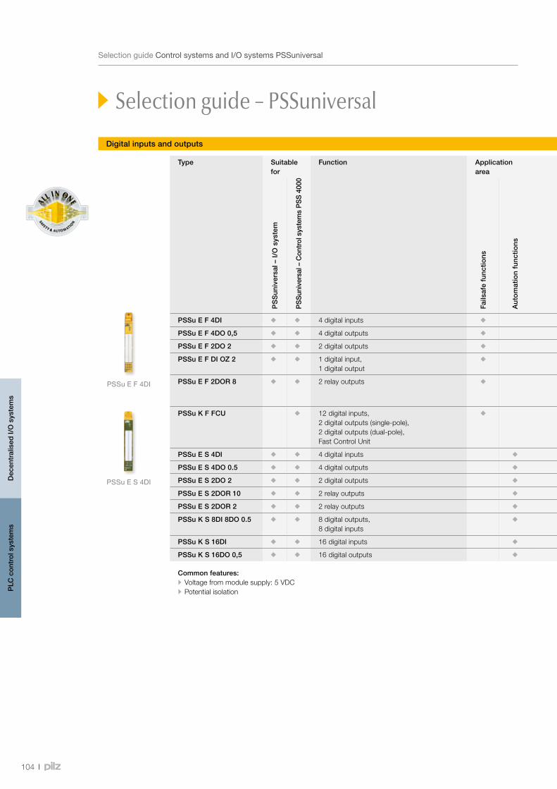
PSSu E S 4DI
PSSu E F 4DI
104
SelectionguideControlsystemsandI/OsystemsPSSuniversal
Digital inputs and outputs
Type Suitable for
Function Application area
Electrical data Order number Screw terminals 1) Cage clamp terminals 1)
PS
Sun
iver
sal –
I/O
sys
tem
PS
Sun
iver
sal –
Con
trol
sys
tem
s P
SS
400
0
Fails
afe
func
tions
Aut
om
atio
n fu
nctio
ns
Feature Inputs Outputs
Regular version
Diagnostic modules (-D)
Ord
er
num
ber
PS
Su
BP
1/8
S 2)
31
2 60
0
PS
Su
BP
-C 1
/8 S
3)
31
2 61
0
PS
Su
BP
1/1
2 S
31
2 61
8
PS
Su
BP
-C 1
/12
S
31
2 62
0
PS
Su
BP
-C1
1/12
S
312
622
PS
Su
BP
2/1
6 S
31
2 62
8
PS
Su
BP
-C 2
/16
S
31
2 63
0
PS
Su
BP
1/8
C 2)
31
2 60
1
PS
Su
BP
-C 1
/8 C
3)
31
2 61
1
PS
Su
BP
1/1
2 C
31
2 61
9
PS
Su
BP
-C 1
/12
C
31
2 62
1
PS
Su
BP
-C1
1/12
C
312
623
PS
Su
BP
2/1
6 C
31
2 62
9
PS
Su
BP
-C 2
/16
C
31
2 63
1
Sui
tab
le
bas
e m
od
ule
PSSu E F 4DI 4 digital inputs - 312 200 1) -
PSSu E F 4DO 0,5 4 digital outputs 0.5 A 312 210 1) -
PSSu E F 2DO 2 2 digital outputs 2 A 312 215 1) -
PSSu E F DI OZ 2 1 digital input, 1 digital output
1 (2 A), dual-pole 1 test pulse output
312 220 1) -
PSSu E F 2DOR 8 2 relay outputs 2 N/OAC1: 250 V/8 A; 2000 VDC1: 24 V/8 A
312 225 1) -
PSSu K F FCU 12 digital inputs, 2 digital outputs (single-pole), 2 digital outputs (dual-pole), Fast Control Unit
-2 (2 A), single-pole2 (2 A), dual-pole
312 437 -
PSSu E S 4DI 4 digital inputs - 312 400 1) 312 401
PSSu E S 4DO 0.5 4 digital outputs 0.5 A 312 405 1) 312 406 1)
PSSu E S 2DO 2 2 digital outputs 2 A 312 410 1) 312 411 1)
PSSu E S 2DOR 10 2 relay outputs 2 N/O 312 510 1) -
PSSu E S 2DOR 2 2 relay outputs 2 N/O 312 511 1) -
PSSu K S 8DI 8DO 0.5 8 digital outputs, 8 digital inputs
0.5 A 312 431 1) -
PSSu K S 16DI 16 digital inputs - 312 430 -
PSSu K S 16DO 0,5 16 digital outputs 0.5 A 312 432 -
Common features:•Voltage from module supply: 5 VDC•Potential isolation
1) ThemodulesarealsoavailableasaT-typeforenhancedenvironmentalrequirements.TheordernumbersfortheT-typemodulesare314…insteadof312…
2)WithoutC-rail3)WithC-rail
Selection guide – PSSuniversal
Dec
entr
alis
ed I/
O s
yste
ms
PLC
con
trol
sys
tem
s
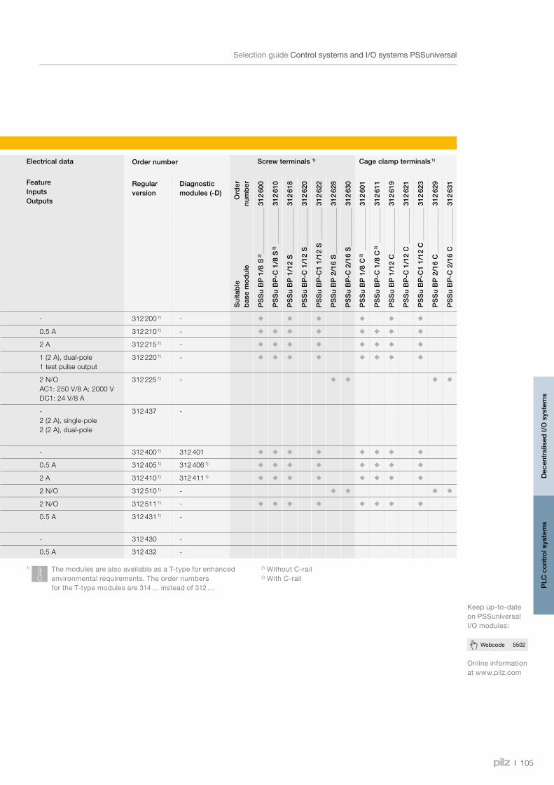
105
Webcode 5502
SelectionguideControlsystemsandI/OsystemsPSSuniversal
Digital inputs and outputs
Onlineinformationatwww.pilz.com
Keepup-to-dateonPSSuniversalI/Omodules:
Type Suitable for
Function Application area
Electrical data Order number Screw terminals 1) Cage clamp terminals 1)
PS
Sun
iver
sal –
I/O
sys
tem
PS
Sun
iver
sal –
Con
trol
sys
tem
s P
SS
400
0
Fails
afe
func
tions
Aut
om
atio
n fu
nctio
ns
Feature Inputs Outputs
Regular version
Diagnostic modules (-D)
Ord
er
num
ber
PS
Su
BP
1/8
S 2)
31
2 60
0
PS
Su
BP
-C 1
/8 S
3)
31
2 61
0
PS
Su
BP
1/1
2 S
31
2 61
8
PS
Su
BP
-C 1
/12
S
31
2 62
0
PS
Su
BP
-C1
1/12
S
312
622
PS
Su
BP
2/1
6 S
31
2 62
8
PS
Su
BP
-C 2
/16
S
31
2 63
0
PS
Su
BP
1/8
C 2)
31
2 60
1
PS
Su
BP
-C 1
/8 C
3)
31
2 61
1
PS
Su
BP
1/1
2 C
31
2 61
9
PS
Su
BP
-C 1
/12
C
31
2 62
1
PS
Su
BP
-C1
1/12
C
312
623
PS
Su
BP
2/1
6 C
31
2 62
9
PS
Su
BP
-C 2
/16
C
31
2 63
1
Sui
tab
le
bas
e m
od
ule
PSSu E F 4DI 4 digital inputs - 312 200 1) -
PSSu E F 4DO 0,5 4 digital outputs 0.5 A 312 210 1) -
PSSu E F 2DO 2 2 digital outputs 2 A 312 215 1) -
PSSu E F DI OZ 2 1 digital input, 1 digital output
1 (2 A), dual-pole 1 test pulse output
312 220 1) -
PSSu E F 2DOR 8 2 relay outputs 2 N/OAC1: 250 V/8 A; 2000 VDC1: 24 V/8 A
312 225 1) -
PSSu K F FCU 12 digital inputs, 2 digital outputs (single-pole), 2 digital outputs (dual-pole), Fast Control Unit
-2 (2 A), single-pole2 (2 A), dual-pole
312 437 -
PSSu E S 4DI 4 digital inputs - 312 400 1) 312 401
PSSu E S 4DO 0.5 4 digital outputs 0.5 A 312 405 1) 312 406 1)
PSSu E S 2DO 2 2 digital outputs 2 A 312 410 1) 312 411 1)
PSSu E S 2DOR 10 2 relay outputs 2 N/O 312 510 1) -
PSSu E S 2DOR 2 2 relay outputs 2 N/O 312 511 1) -
PSSu K S 8DI 8DO 0.5 8 digital outputs, 8 digital inputs
0.5 A 312 431 1) -
PSSu K S 16DI 16 digital inputs - 312 430 -
PSSu K S 16DO 0,5 16 digital outputs 0.5 A 312 432 -
Common features:•Voltage from module supply: 5 VDC•Potential isolation
1) ThemodulesarealsoavailableasaT-typeforenhancedenvironmentalrequirements.TheordernumbersfortheT-typemodulesare314…insteadof312…
2)WithoutC-rail3)WithC-rail
Selection guide – PSSuniversal
Dec
entr
alis
ed I/
O s
yste
ms
PLC
con
trol
sys
tem
s
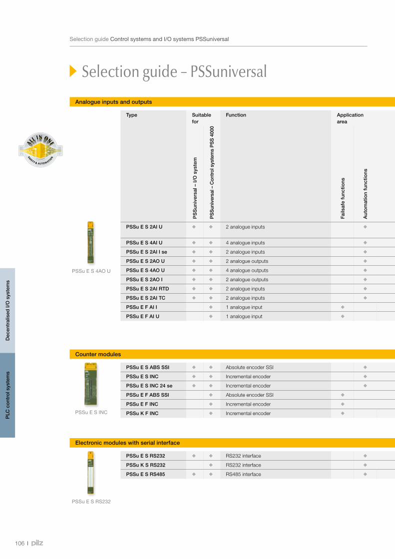
PSSu E S 4AOU
PSSuESRS232
PSSuE S INC
106
SelectionguideControlsystemsandI/OsystemsPSSuniversal
Selection guide – PSSuniversal
Analogue inputs and outputs
Counter modules
Electronic modules with serial interface
Type Suitable for
Function Application area
Electrical data Order number
Screw terminals 1) Cage clamp terminals 1)
PS
Sun
iver
sal –
I/O
sys
tem
PS
Sun
iver
sal –
Con
trol
sys
tem
s P
SS
400
0
Fails
afe
func
tions
Aut
om
atio
n fu
nctio
ns
Feature Inputs Outputs O
rder
nu
mb
er
PS
Su
BP
1/8
S 2)
31
2 60
0
PS
Su
BP
-C 1
/8 S
3)
31
2 61
0
PS
Su
BP
1/8
S-J
31
2 60
2
PS
Su
BP
-C 1
/8 S
-J
31
2 61
2
PS
Su
BP
1/1
2 S
31
2 61
8
PS
Su
BP
-C 1
/12
S
31
2 62
0
PS
Su
BP
-C1
1/12
S
312
622
PS
Su
BP
2/1
6 S
31
2 62
8
PS
Su
BP
-C 2
/16
S
31
2 63
0
PS
Su
BP
1/8
C 2)
31
2 61
1
PS
Su
BP
-C 1
/8 C
3)
31
2 61
2
PS
Su
BP
1/8
C-J
31
2 60
3
PS
Su
BP
-C 1
/8 C
-J
312
613
PS
Su
BP
1/1
2 C
31
2 61
9
PS
Su
BP
-C 1
/12
C
31
2 62
1
PS
Su
BP
-C1
1/12
C
312
623
PS
Su
BP
2/1
6 C
31
2 62
9
PS
Su
BP
-C 2
/16
C
31
2 63
1
Sui
tab
le
bas
e m
od
ule
PSSu E S 2AI U 2 analogue inputs 0 … 10 V s.e.; diff; -10 … +10 V
312 440 1)
PSSu E S 4AI U 4 analogue inputs 0 … 10 V s.e. 312 445 1)
PSSu E S 2AI I se 2 analogue inputs 0 … 20 mA; 4 … 20 mA 312 450 1)
PSSu E S 2AO U 2 analogue outputs 0 … 10 V; -10 … +10 V 312 460 1)
PSSu E S 4AO U 4 analogue outputs 0 … 10 V 312 465 1)
PSSu E S 2AO I 2 analogue outputs 0 … 20 mA; 4 … 20 mA 312 470 1)
PSSu E S 2AI RTD 2 analogue inputs - 312 490 1)
PSSu E S 2AI TC 2 analogue inputs Thermocouples 312 500 1)
PSSu E F AI I 1 analogue input 0 … 25 mA 312 260 1)
PSSu E F AI U 1 analogue input -10 … +10 V 312 265 1)
PSSu E S ABS SSI Absolute encoder SSI SSI 312 480 1)
PSSu E S INC Incremental encoder INC 312 485 1)
PSSu E S INC 24 se Incremental encoder INC 312 486 1)
PSSu E F ABS SSI Absolute encoder SSI SSI 312 275 1)
PSSu E F INC Incremental encoder INC 312 280 1)
PSSu K F INC Incremental encoder INC 312 437 1)
PSSu E S RS232 RS232 interface - 312 515 1)
PSSu K S RS232 RS232 interface - 312 438 1)
PSSu E S RS485 RS485 interface - 312 516 1)
1) ThemodulesarealsoavailableasaT-typeforenhancedenvironmentalrequirements.TheordernumbersfortheT-typemodulesare314…insteadof312…
2)WithoutC-rail3)WithC-rail
Dec
entr
alis
ed I/
O s
yste
ms
PLC
con
trol
sys
tem
s
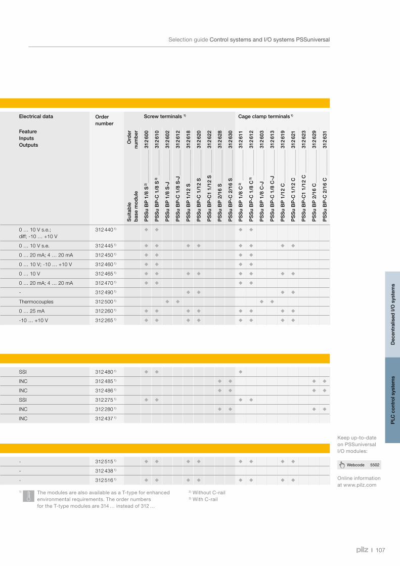
107
Webcode 5502
SelectionguideControlsystemsandI/OsystemsPSSuniversal
Selection guide – PSSuniversal
Analogue inputs and outputs
Counter modules
Electronic modules with serial interface
Type Suitable for
Function Application area
Electrical data Order number
Screw terminals 1) Cage clamp terminals 1)
PS
Sun
iver
sal –
I/O
sys
tem
PS
Sun
iver
sal –
Con
trol
sys
tem
s P
SS
400
0
Fails
afe
func
tions
Aut
om
atio
n fu
nctio
ns
Feature Inputs Outputs O
rder
nu
mb
er
PS
Su
BP
1/8
S 2)
31
2 60
0
PS
Su
BP
-C 1
/8 S
3)
31
2 61
0
PS
Su
BP
1/8
S-J
31
2 60
2
PS
Su
BP
-C 1
/8 S
-J
31
2 61
2
PS
Su
BP
1/1
2 S
31
2 61
8
PS
Su
BP
-C 1
/12
S
31
2 62
0
PS
Su
BP
-C1
1/12
S
312
622
PS
Su
BP
2/1
6 S
31
2 62
8
PS
Su
BP
-C 2
/16
S
31
2 63
0
PS
Su
BP
1/8
C 2)
31
2 61
1
PS
Su
BP
-C 1
/8 C
3)
31
2 61
2
PS
Su
BP
1/8
C-J
31
2 60
3
PS
Su
BP
-C 1
/8 C
-J
312
613
PS
Su
BP
1/1
2 C
31
2 61
9
PS
Su
BP
-C 1
/12
C
31
2 62
1
PS
Su
BP
-C1
1/12
C
312
623
PS
Su
BP
2/1
6 C
31
2 62
9
PS
Su
BP
-C 2
/16
C
31
2 63
1
Sui
tab
le
bas
e m
od
ule
PSSu E S 2AI U 2 analogue inputs 0 … 10 V s.e.; diff; -10 … +10 V
312 440 1)
PSSu E S 4AI U 4 analogue inputs 0 … 10 V s.e. 312 445 1)
PSSu E S 2AI I se 2 analogue inputs 0 … 20 mA; 4 … 20 mA 312 450 1)
PSSu E S 2AO U 2 analogue outputs 0 … 10 V; -10 … +10 V 312 460 1)
PSSu E S 4AO U 4 analogue outputs 0 … 10 V 312 465 1)
PSSu E S 2AO I 2 analogue outputs 0 … 20 mA; 4 … 20 mA 312 470 1)
PSSu E S 2AI RTD 2 analogue inputs - 312 490 1)
PSSu E S 2AI TC 2 analogue inputs Thermocouples 312 500 1)
PSSu E F AI I 1 analogue input 0 … 25 mA 312 260 1)
PSSu E F AI U 1 analogue input -10 … +10 V 312 265 1)
PSSu E S ABS SSI Absolute encoder SSI SSI 312 480 1)
PSSu E S INC Incremental encoder INC 312 485 1)
PSSu E S INC 24 se Incremental encoder INC 312 486 1)
PSSu E F ABS SSI Absolute encoder SSI SSI 312 275 1)
PSSu E F INC Incremental encoder INC 312 280 1)
PSSu K F INC Incremental encoder INC 312 437 1)
PSSu E S RS232 RS232 interface - 312 515 1)
PSSu K S RS232 RS232 interface - 312 438 1)
PSSu E S RS485 RS485 interface - 312 516 1)
1) ThemodulesarealsoavailableasaT-typeforenhancedenvironmentalrequirements.TheordernumbersfortheT-typemodulesare314…insteadof312…
2)WithoutC-rail3)WithC-rail
Onlineinformationatwww.pilz.com
Keepup-to-dateonPSSuniversalI/Omodules:
Dec
entr
alis
ed I/
O s
yste
ms
PLC
con
trol
sys
tem
s

PSSuXB F-T
PSSuXRF-T
SD Memory Card 512MB
108
Webcode 5502
SelectionguidePSSuniversalaccessories
Selection guide – PSSuniversal accessories
Type Function Order number
Suitable for
PSSu XB F-T Base station used to extend the PSSu module bus by 0.5 m or 1 m, inside the control cabinet
314 092 1) • PSSu BP 2/16 S 312 628
• PSSu BP 2/16 C 312 629
• PSSu BP-C 2/16 S 312 630
• PSSu BP-C 2/16 C 312 631
PSSu XR F-T Remote station used to extend the PSSu module bus by 0.5 m or 1 m, inside the control cabinet
314 093 1) Connection cable PSSu A RJ45-CAB 1.5M 314 094
PSSu A ET End bracket for top-hat rail 312 900 -
PSSu A ETM End bracket for top-hat rail, metal version, for high mechanical stresses
312 901 -
PSSu A EC Terminating plate with integral terminating resistor
312 902314 902 1)
-
PSSu A ET PE Earthing terminal for top-hat rail, PE connection, Gr/Y
312 949 -
PSSu A USB-CAB03 PSSu USB cable, length 3 m 312 992 -
PSSu A USB-CAB05 PSSu USB cable, length 5 m 312 993 -
SD Memory Card 512MB
512 MB SD memory card for PSSu head modules
313 100 -
PSSu A Con 1/4 S Connector set for power supply, 1-row, 4-pin, screw connection
313 110 Head modules in the automation system PSS 4000 (page 100)
PSSu A Con 2/8 C Connector set for power supply, 2-row, 8-pin, spring loaded connection
313 111 Head modules in the automation system PSS 4000 (page 100)
PSSu A Con 1/10 C Connector set for compact modules, 1-row, 10-pin, spring loaded connection
313 115 -
PSSu A Con 3/30 C Connector set for compact modules, 3-row, 30-pin, spring loaded connection
313 116 -
PSSu A Con 4 S Connector for compact modules, 4-pin, screw connection, crosslinked polyethylene 1 connector
313 117 -
1) ThemodulesarealsoavailableasaT-typeforenhancedenvironmentalrequirements.
PSSuniversal accessories
Onlineinformationatwww.pilz.com
Keepup-to-dateonPSSuniversalaccessories:
Dec
entr
alis
ed I/
O s
yste
ms
PLC
con
trol
sys
tem
s
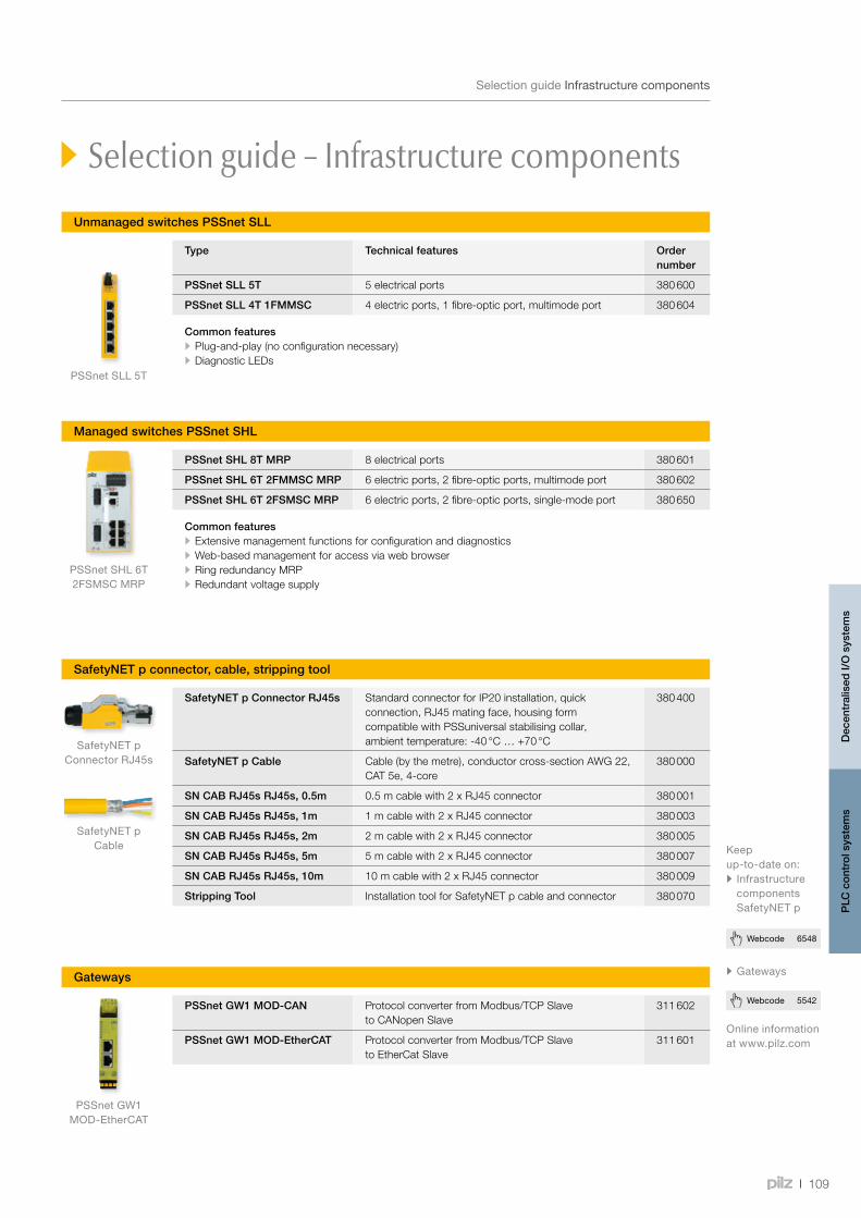
PSSnet SLL 5T
PSSnet SHL 6T2FSMSC MRP
SafetyNET pConnector RJ45s
PSSnet GW1MOD-EtherCAT
SafetyNET pCable
109
Webcode 5542
Webcode 6548
SelectionguideInfrastructurecomponents
Type Technical features Order number
PSSnet SLL 5T 5 electrical ports 380 600
PSSnet SLL 4T 1FMMSC 4 electric ports, 1 fibre-optic port, multimode port 380 604
Common features • Plug-and-play (no configuration necessary) • Diagnostic LEDs
Unmanaged switches PSSnet SLL
PSSnet SHL 8T MRP 8 electrical ports 380 601
PSSnet SHL 6T 2FMMSC MRP 6 electric ports, 2 fibre-optic ports, multimode port 380 602
PSSnet SHL 6T 2FSMSC MRP 6 electric ports, 2 fibre-optic ports, single-mode port 380 650
Common features • Extensive management functions for configuration and diagnostics • Web-based management for access via web browser • Ring redundancy MRP • Redundant voltage supply
SafetyNET p Connector RJ45s Standard connector for IP20 installation, quick connection, RJ45 mating face, housing form compatible with PSSuniversal stabilising collar, ambient temperature: -40 °C … +70 °C
380 400
SafetyNET p Cable Cable (by the metre), conductor cross-section AWG 22, CAT 5e, 4-core
380 000
SN CAB RJ45s RJ45s, 0.5m 0.5 m cable with 2 x RJ45 connector 380 001
SN CAB RJ45s RJ45s, 1m 1 m cable with 2 x RJ45 connector 380 003
SN CAB RJ45s RJ45s, 2m 2 m cable with 2 x RJ45 connector 380 005
SN CAB RJ45s RJ45s, 5m 5 m cable with 2 x RJ45 connector 380 007
SN CAB RJ45s RJ45s, 10m 10 m cable with 2 x RJ45 connector 380 009
Stripping Tool Installation tool for SafetyNET p cable and connector 380 070
PSSnet GW1 MOD-CAN Protocol converter from Modbus/TCP Slave to CANopen Slave
311 602
PSSnet GW1 MOD-EtherCAT Protocol converter from Modbus/TCP Slave to EtherCat Slave
311 601
Gateways
Selection guide – Infrastructure components
Managed switches PSSnet SHL
SafetyNET p connector, cable, stripping tool
Onlineinformationatwww.pilz.com
Keepup-to-dateon:• InfrastructurecomponentsSafetyNETp
•Gateways
Dec
entr
alis
ed I/
O s
yste
ms
PLC
con
trol
sys
tem
s
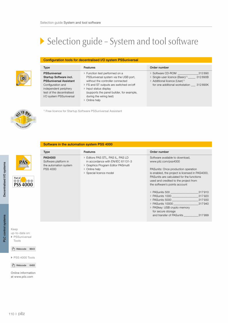
110
Webcode 6493
Webcode 8643
Webcode 6493
SelectionguideSystemandtoolsoftware
Selection guide – System and tool software
Type Features Order number
PSSuniversal Startup Software incl. PSSuniversal AssistantConfiguration and independent periphery test of the decentralised I/O system PSSuniversal
•Function test performed on a PSSuniversal system via the USB port, without the controller connected
•FS and ST outputs are switched on/off• Input status display
(supports the panel builder, for example, during the wiring test)
•Online help
•Software CD-ROM ______________312 890•Single-user licence (Basic) 1) _____ 312 890B•Additional licence (User) 1)
for one additional workstation ___ 312 890K
1)FreelicenceforStartupSoftwarePSSuniversalAssistant
Configuration tools for decentralised I/O system PSSuniversal
Software in the automation system PSS 4000
Type Features Order number
PAS4000Software platform in the automation system PSS 4000
•Editors PAS STL, PAS IL, PAS LD in accordance with EN/IEC 61131-3
•Graphics Program Editor PASmulti•Online help•Special licence model
Software available to download, www.pilz.com/pss4000
PASunits: Once production operation is enabled, the project is licensed in PAS4000, PASunits are calculated for the functions used and credited to the project from the software’s points account
•PASunits 500 ___________________317 910•PASunits 1000 __________________317 920•PASunits 5000 __________________317 930•PASunits 10000 _________________317 940•PASkey: USB crypto memory
for secure storage and transfer of PASunits __________317 999
Onlineinformationatwww.pilz.com
Keepup-to-dateon:• PSSuniversalTools
• PSS 4000Tools
Onlineinformationatwww.pilz.com
Dec
entr
alis
ed I/
O s
yste
ms
PLC
con
trol
sys
tem
s

FS_EmergencyStop
FS_TwoHandControl
FS_IncrementalEncoder
FS_CamController
111
Webcode 6493
SelectionguideSoftwareblocksPAS4000
Selection guide – Software blocks PAS4000
Type Function
FSEmergencyStop Configures and monitors the function of E-STOP pushbuttons with one or two N/C contacts.
FSLightCurtain Monitors the function of light grids with 2 N/C contacts.
FSSafetyGate Monitors the function of safety gate switches with up to 3 contacts.
FSOperating ModeSelectorSwitch
Monitors up to 8 positions on an operating mode selector switch. Unneeded inputs may remain unassigned. Once the switchover time has elapsed, only one contact at a time may be closed.
FSSafetyValve Monitors the operation of safety valves of the single, double or directional type.
FSTwoHandControl Monitors whether the two pushbuttons of the two-hand control are operated simultaneously (within 0.5 s). In accordance with EN 574, two-hand pushbuttons of type IIIA (2 N/O contacts) or type IIIC (combination of 2 N/O and 2 N/C contacts) can be used.
FSMuting Used to temporarily suspend safety functions (ESPE/AOPD) without interrupting the process (muting), in accordance with EN 61496-1.
FSCounterDual In conjunction with the blocks FS_AbsoluteEncoder and/or FS_IncrementalEncoder, calculates the following safe values: Position, speed, standstill.
FSAbsolute Encoder
Calculates a counter status (in increments) from the measured value from the absolute encoder and monitors the module status.
FSIncremental Encoder
Initialises the counter, calculates the current counter status (in increments) and transmits status information.
FSAnalogueInput Dual
Monitors redundant, analogue input values for upward violation of a value range, downward violation of a value range and upward violation of a difference between the analogue input value 0 and analogue input value 1 over a defined period of time (feasibility check).
FSScaling Scales an analogue input value and sends it to an O-variable.
FSPressOperating Modes
Controls and monitors the setup, single stroke and automatic operating modes of a mechanical press.
FSCamEvaluation Monitors the mechanical rotary cam arrangement of a press for: Feasibility of the signals from the overrun cam and run-up cam, failure of the dynamic cam and overrun cam, upward violation of the overrun at top dead centre.
FSCycleMode LightCurtain
Enables cycle mode (control) for triggering the press stroke when using a light curtain in the standard and Sweden operating modes.
FSCamController Provides the position signals for a press control. It uses the angle values, e.g. from the block S_PositionToAngle, to determine the signal for achieving top dead centre, enabling the press to be shut down. It is used in a safe, electronic rotary cam arrangement.
ThesoftwaremodulesofthePAS4000canbefounddirectlyusingthetoolinthesoftwarelibrary.Tooldownload:www.pilz.com/PSS4000
General failsafe control blocks
Hardware-related blocks
Press control blocks
Onlineinformationatwww.pilz.com
Keepup-to-dateonPAS4000
Dec
entr
alis
ed I/
O s
yste
ms
PLC
con
trol
sys
tem
s
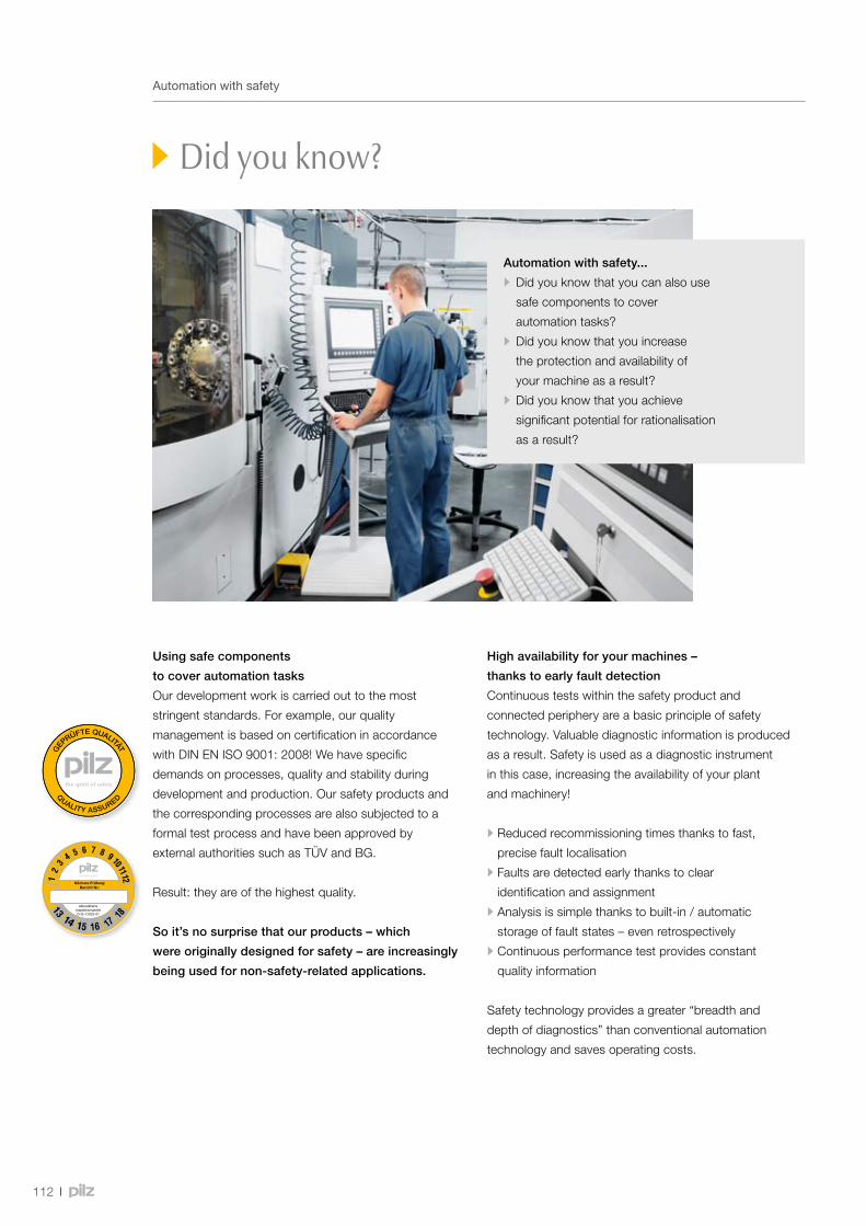
QUALITY ASSURED
GEP
RÜFTE QUALITÄT
112
Automationwithsafety
Did you know?
Using safe components
to cover automation tasks
Our development work is carried out to the most
stringent standards. For example, our quality
management is based on certification in accordance
with DIN EN ISO 9001: 2008! We have specific
demands on processes, quality and stability during
development and production. Our safety products and
the corresponding processes are also subjected to a
formal test process and have been approved by
external authorities such as TÜV and BG.
Result: they are of the highest quality.
So it’s no surprise that our products – which
were originally designed for safety – are increasingly
being used for non-safety-related applications.
High availability for your machines –
thanks to early fault detection
Continuous tests within the safety product and
connected periphery are a basic principle of safety
technology. Valuable diagnostic information is produced
as a result. Safety is used as a diagnostic instrument
in this case, increasing the availability of your plant
and machinery!
•Reduced recommissioning times thanks to fast,
precise fault localisation
•Faults are detected early thanks to clear
identification and assignment
•Analysis is simple thanks to built-in / automatic
storage of fault states – even retrospectively
•Continuous performance test provides constant
quality information
Safety technology provides a greater “breadth and
depth of diagnostics” than conventional automation
technology and saves operating costs.
Automation with safety...
• Did you know that you can also use
safe components to cover
automation tasks?
• Did you know that you increase
the protection and availability of
your machine as a result?
• Did you know that you achieve
significant potential for rationalisation
as a result?

PNOZ m B0
113
Automationwithsafety
Products that won’t be thrown off course
The level and requirements of the safety technology
are very high – so our safety components have a
dual-channel structure, for example. Extensive
module tests (in accordance with IEC 61508) are
a matter of course.
Also, all our components comply with the EMC Directive
and can be used in an extended temperature range, so
they are particularly robust. They withstand environmental
influences, are less susceptible to faults and highly
available within the application.
•High safety requirements –
can be transferred to the automation technology
•High-quality products for lasting availability
•Good diagnostic options due to
safety components in general automation functions
•Robust, hard-wearing products –
comply with the EMC Directive
Potential for rationalisation:
safety components cover automation tasks
Take control technology as an example: the configurable control
systems PNOZmulti are mainly used to implement multiple safety functions.
They are also powerful enough to assume complete machine control on
smaller machines. Machine builders and operators can rely on high-quality,
available products. What’s special here is that they do not need an additional
control system and so can make savings in many different areas. Reduce
your hardware costs and enjoy having space in the control cabinet
(the PNOZmulti 2 base unit is only 45 mm wide!). So you can keep your
purchasing and stockholding costs low.
You have just one contact for safety and automation!

114
Webcode 7792
Services Consulting, engineering and training
Consulting, engineering and training
As a solution supplier, Pilz can help you to apply optimum safety strategies worldwide. Services encompass the whole machine lifecycle. Our training package with practical, up-to-date course content completes the offering.
We are your reliable service provider for plant and machinery safety
Your projects belong in our safe hands!
Online information at www.pilz.com
Services related to machinery safety:
Risk assessment
We inspect your machinery in accordance with the applicable national and/or
international standards and directives and assess the existing hazards.
Safety concept
We develop detailed technical solutions for the safety of your plant and machinery
through mechanical, electronic and organisational measures.
Safety design
The aim of the safety design is to reduce or eliminate danger points through
detailed planning of the necessary safeguards.
System implementation
The results of the risk analysis and safety design are implemented to suit the particular
requirements through selected safety measures.
Our management system was certified in the field of system integration to EN/IEC 61508.
Safety validation
In the safety validation, the risk assessment and safety concept are mirrored
and inspected by competent, specialist staff.
CE marking
We control all activities and processes for the necessary conformity assessment procedure,
including the technical documentation that is required.
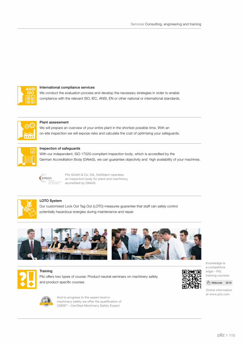
®
115
Webcode 0218
Consulting, engineering and training
Services Consulting, engineering and training
Online information at www.pilz.com
Knowledge is a competitive edge – Pilz training courses:
Inspection of safeguards
With our independent, ISO 17020-compliant inspection body, which is accredited by the
German Accreditation Body (DAkkS), we can guarantee objectivity and high availability of your machines.
Pilz GmbH & Co. KG, Ostfildern operates an inspection body for plant and machinery, accredited by DAkkS.
Plant assessment
We will prepare an overview of your entire plant in the shortest possible time. With an
on-site inspection we will expose risks and calculate the cost of optimising your safeguards.
International compliance services
We conduct the evaluation process and develop the necessary strategies in order to enable
compliance with the relevant ISO, IEC, ANSI, EN or other national or international standards.
LOTO System
Our customised Lock Out Tag Out (LOTO) measures guarantee that staff can safely control
potentially hazardous energies during maintenance and repair.
Training
Pilz offers two types of course: Product-neutral seminars on machinery safety
and product-specific courses
And to progress to the expert level in machinery safety we offer the qualification of CMSE® – Certified Machinery Safety Expert.
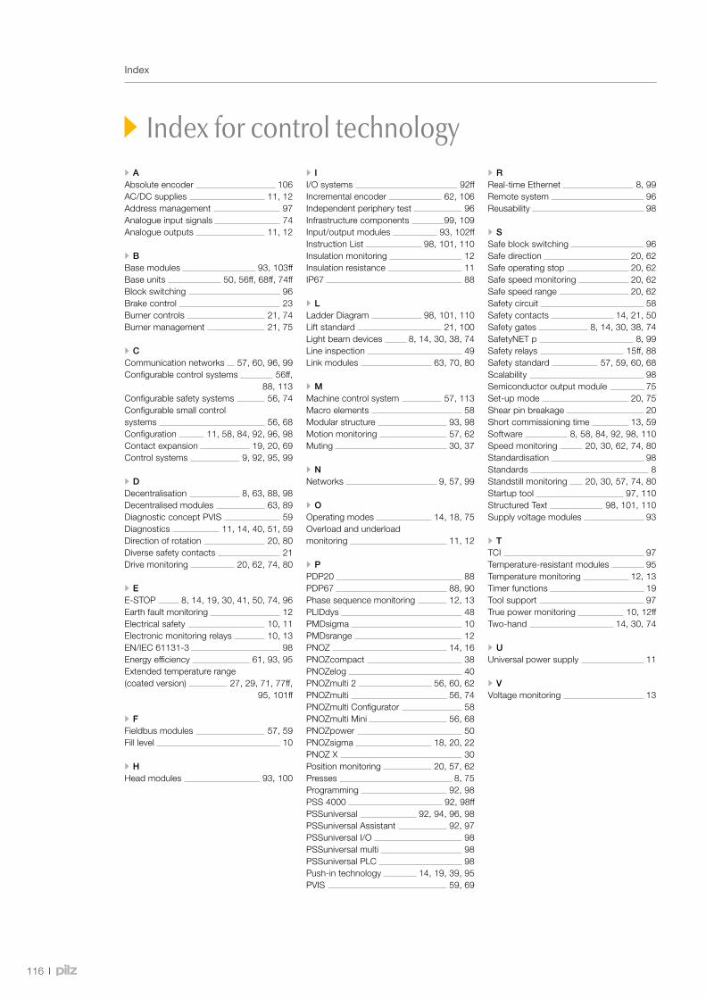
116
Index
Index for control technology•AAbsolute encoder 106AC/DC supplies 11, 12Address management 97Analogue input signals 74Analogue outputs 11, 12
•BBase modules 93, 103ffBase units 50, 56ff, 68ff, 74ffBlock switching 96Brake control 23Burner controls 21, 74Burner management 21, 75
•CCommunication networks 57, 60, 96, 99Configurable control systems 56ff, 88, 113Configurable safety systems 56, 74Configurable small control systems 56, 68Configuration 11, 58, 84, 92, 96, 98Contact expansion 19, 20, 69Control systems 9, 92, 95, 99
•DDecentralisation 8, 63, 88, 98Decentralised modules 63, 89Diagnostic concept PVIS 59Diagnostics 11, 14, 40, 51, 59Direction of rotation 20, 80Diverse safety contacts 21Drive monitoring 20, 62, 74, 80
•EE-STOP 8, 14, 19, 30, 41, 50, 74, 96Earth fault monitoring 12Electrical safety 10, 11Electronic monitoring relays 10, 13EN/IEC 61131-3 98Energy efficiency 61, 93, 95Extended temperature range (coated version) 27, 29, 71, 77ff, 95, 101ff
•FFieldbus modules 57, 59Fill level 10
•HHead modules 93, 100
• II/O systems 92ffIncremental encoder 62, 106Independent periphery test 96Infrastructure components 99, 109Input/output modules 93, 102ffInstruction List 98, 101, 110Insulation monitoring 12Insulation resistance 11IP67 88
•LLadder Diagram 98, 101, 110Lift standard 21, 100Light beam devices 8, 14, 30, 38, 74Line inspection 49Link modules 63, 70, 80
•MMachine control system 57, 113Macro elements 58Modular structure 93, 98Motion monitoring 57, 62Muting 30, 37
•NNetworks 9, 57, 99
•OOperating modes 14, 18, 75Overload and underload monitoring 11, 12
•PPDP20 88PDP67 88, 90Phase sequence monitoring 12, 13PLIDdys 48PMDsigma 10PMDsrange 12PNOZ 14, 16PNOZcompact 38PNOZelog 40PNOZmulti 2 56, 60, 62PNOZmulti 56, 74PNOZmulti Configurator 58PNOZmulti Mini 56, 68PNOZpower 50PNOZsigma 18, 20, 22PNOZ X 30Position monitoring 20, 57, 62Presses 8, 75Programming 92, 98PSS 4000 92, 98ffPSSuniversal 92, 94, 96, 98PSSuniversal Assistant 92, 97PSSuniversal I/O 98PSSuniversal multi 98PSSuniversal PLC 98Push-in technology 14, 19, 39, 95PVIS 59, 69
•RReal-time Ethernet 8, 99Remote system 96Reusability 98
•SSafe block switching 96Safe direction 20, 62Safe operating stop 20, 62Safe speed monitoring 20, 62Safe speed range 20, 62Safety circuit 58Safety contacts 14, 21, 50Safety gates 8, 14, 30, 38, 74SafetyNET p 8, 99Safety relays 15ff, 88Safety standard 57, 59, 60, 68Scalability 98Semiconductor output module 75Set-up mode 20, 75Shear pin breakage 20Short commissioning time 13, 59Software 8, 58, 84, 92, 98, 110Speed monitoring 20, 30, 62, 74, 80Standardisation 98Standards 8Standstill monitoring 20, 30, 57, 74, 80Startup tool 97, 110Structured Text 98, 101, 110Supply voltage modules 93
•TTCI 97Temperature-resistant modules 95Temperature monitoring 12, 13Timer functions 19Tool support 97True power monitoring 10, 12ffTwo-hand 14, 30, 74
•UUniversal power supply 11
•VVoltage monitoring 13


Contact
ATPilz Ges.m.b.H.Sichere AutomationModecenterstraße 141030 WienAustriaTelephone: +43 1 7986263-0Telefax: +43 1 7986264E-Mail: [email protected]: www.pilz.at
AUPilz AustraliaSafe AutomationUnit D7, Hallmarc Business park ClaytonCorner of Westall and Centre roadsClayton, Melbourne, Victoria 3168AustraliaTelephone: +61 3 95446300Telefax: +61 3 95446311E-Mail: [email protected]: www.pilz.com.au
BE, LUPilz BelgiumSafe AutomationBijenstraat 49051 Gent (Sint-Denijs-Westrem)BelgiumTelephone: +32 9 3217570Telefax: +32 9 3217571E-Mail: [email protected]: www.pilz.be
BRPilz do Brasil Automação Segura Av. Senador Vergueiro, 347/355 -Jd. do Mar CEP: 09750-000 São Bernardo do Campo - SP BrazilTelephone: +55 11 4126-7290Telefax: +55 11 4942-7002E-Mail: [email protected]: www.pilz.com.br
CAPilz Automation Safety Canada L.P.250 Bayview DriveBarrie, OntarioCanada, L4N 4Y8Telephone: +1 705 481-7459Telefax: +1 705 481-7469E-Mail: [email protected]: www.pilz.ca
CHPilz lndustrieelektronik GmbHGewerbepark Hintermättli5506 MägenwilSwitzerlandTelephone: +41 62 88979-30Telefax: +41 62 88979-40E-Mail: [email protected]: www.pilz.ch
CNPilz Industrial AutomationTrading (Shanghai) Co., Ltd.Rm. 1702-1704Yongda International TowerNo. 2277 Long Yang RoadShanghai 201204ChinaTelephone: +86 21 60880878Telefax: +86 21 60880870E-Mail: [email protected]: www.pilz.com.cn
CZ, SKPilz Czech s.r.o Safe AutomationZelený pruh 1560/99 140 00 Praha 4 Czech Republic Telephone: +420 222 135353Telefax: +420 296 374788E-Mail: [email protected]: www.pilz.cz
DEPilz GmbH & Co. KG Felix-Wankel-Straße 273760 OstfildernGermanyTelephone: +49 711 3409-0Telefax: +49 711 3409-133E-Mail: [email protected]: www.pilz.de
DKPilz Skandinavien K/SSafe AutomationEllegaardvej 25 L6400 SonderborgDenmarkTelephone: +45 74436332Telefax: +45 74436342E-Mail: [email protected]: www.pilz.dk
ESPilz lndustrieelektronik S.L.Safe AutomationCamí Ral, 130Polígono Industrial Palou Nord08401 GranollersSpainTelephone: +34 938497433Telefax: +34 938497544E-Mail: [email protected]: www.pilz.es
FIPilz Skandinavien K/SSafe AutomationNuijamiestentie 700400 HelsinkiFinlandTelephone: +358 10 3224030Telefax: +358 9 27093709E-Mail: [email protected]: www.pilz.fi
FRPilz France Electronic1, rue Jacob MayerCS 8001267037 Strasbourg Cedex 2FranceTelephone: +33 3 88104000Telefax: +33 3 88108000E-Mail: [email protected]: www.pilz.fr
GBPilz Automation Ltd Pilz House Little Colliers Field Corby, Northants NN18 8TJ United KingdomTelephone: +44 1536 460766Telefax: +44 1536 460866E-Mail: [email protected]: www.pilz.co.uk
IEPilz Ireland Industrial AutomationCork Business and Technology ParkModel Farm RoadCorkIrelandTelephone: +353 21 4346535Telefax: +353 21 4804994E-Mail: [email protected]: www.pilz.ie
In many countries we are represented by sales partners. Please refer to our homepage
www.pilz.com for further details or contact our headquarters.

The Best of German Engineering
Partner of:
Contact
INPilz India Pvt Ltd.Office No 202, Delite SquareNear Aranyeshwar TempleSahakar Nagar No 1Pune 411009IndiaTelephone: +91 20 2421399-4/-5Telefax: +91 20 2421399-6E-Mail: [email protected]: www.pilz.in
ITPilz ltalia S.r.l.Automazione sicuraVia Gran Sasso n. 120823 Lentate sul Seveso (MB)ItalyTelephone: +39 0362 1826711Telefax: +39 0362 1826755E-Mail: [email protected]: www.pilz.it
JPPilz Japan Co., Ltd.Safe AutomationIchigo Shin-Yokohama Bldg. 4F 3-17-5 Shin-YokohamaKohoku-ku222-0033 YokohamaJapanTelephone: +81 45 471-2281Telefax: +81 45 471-2283E-Mail: [email protected]: www.pilz.jp
KRPilz Korea Ltd.Safe Automation22F KeumkangPenterium IT Tower Unit B810 Gwanyang-dong, Dongan-guAnyang-si, Gyeonggi-do, 431-060South KoreaTelephone: +82 31 450 0677Telefax: +82 31 450 0670E-Mail: [email protected]: www.pilz.co.kr
MXPilz de México, S. de R.L. de C.V.Automatización SeguraConvento de Actopan 36Jardines de Santa MónicaTlalnepantla, Méx. 54050MexicoTelephone: +52 55 5572 1300Telefax: +52 55 5572 1300E-Mail: [email protected]: www.pilz.mx
NLPilz NederlandVeilige automatiseringHavenweg 224131 NM VianenNetherlandsTelephone: +31 347 320477Telefax: +31 347 320485E-Mail: [email protected]: www.pilz.nl
NZPilz New ZealandSafe AutomationUnit 4, 12 Laidlaw WayEast Tamaki Auckland 2016New ZealandTelephone: +64 9 6345350Telefax: +64 9 6345352E-Mail: [email protected]: www.pilz.co.nz
PLPilz Polska Sp. z o.o.Safe Automationul. Ruchliwa 1502-182 WarszawaPolandTelephone: +48 22 8847100Telefax: +48 22 8847109E-Mail: [email protected]: www.pilz.pl
PTPilz Industrieelektronik S.L.R. Eng Duarte Pacheco, 1204 Andar Sala 214470-174 MaiaPortugalTelephone: +351 229407594Telefax: +351 229407595E-Mail: [email protected]: www.pilz.pt
RUPilz RUS OOOUgreshskaya street, 2,bldg. 11, office 16 (1st floor)115088 MoskauRussian FederationTelephone: +7 495 665 4993E-Mail: [email protected]: www.pilzrussia.ru
SEPilz Skandinavien K/SSafe AutomationEnergigatan 10 B43437 KungsbackaSwedenTelephone: +46 300 13990Telefax: +46 300 30740E-Mail: [email protected]: www.pilz.se
TRPilz Emniyet Otomasyon Ürünleri ve Hizmetleri Tic. Ltd. Şti.Kayışdağı Mahallesi Dudullu Yolu Cad. Mecnun Sok. Duru Plaza No:7 34755 Ataşehir/İstanbul TurkeyTelephone: +90 216 5775550Telefax: +90 216 5775549E-Mail: [email protected]: www.pilz.com.tr
TWPilz Taiwan Ltd.7F.-3, No. 146, Songjiang Rd.Zhongshan Dist., Taipei City104, TaiwanTelephone: +886 2 2568 1680Telefax: +886 2 2568 1600E-Mail: [email protected]: www.pilz.tw
USPilz Automation Safety L.P.7150 Commerce BoulevardCantonMichigan 48187USATelephone: +1 734 354 0272Telefax: +1 734 354 3355E-Mail: [email protected]: www.pilz.us
In many countries we are represented by sales partners. Please refer to our homepage
www.pilz.com for further details or contact our headquarters.
RUPilz RUS OOOUgreshskaya street, 2,bldg. 11, office 16 (1st floor)115088 MoskauRussian FederationTelephone: +7 495 665 4993E-Mail: [email protected]: www.pilzrussia.ru
SEPilz Skandinavien K/SSafe AutomationEnergigatan 10 B43437 KungsbackaSwedenTelephone: +46 300 13990Telefax: +46 300 30740E-Mail: [email protected]: www.pilz.se
TRPilz Emniyet Otomasyon Ürünleri ve Hizmetleri Tic. Ltd. Şti.Kayışdağı Mahallesi Dudullu Yolu Cad. Mecnun Sok. Duru Plaza No:7 34755 Ataşehir/İstanbul TurkeyTelephone: +90 216 5775550Telefax: +90 216 5775549E-Mail: [email protected]: www.pilz.com.tr
TWPilz Taiwan Ltd.7F.-3, No. 146, Songjiang Rd.Zhongshan Dist., Taipei City104, TaiwanTelephone: +886 2 2568 1680Telefax: +886 2 2568 1600E-Mail: [email protected]: www.pilz.tw
USPilz Automation Safety L.P.7150 Commerce BoulevardCantonMichigan 48187USATelephone: +1 734 354 0272Telefax: +1 734 354 3355E-Mail: [email protected]: www.pilz.us
SupportTechnical support is available from Pilz round the clock.
Americas
Brazil
+55 11 97569-2804
Canada
+1 888-315-PILZ (315-7459)
Mexico
+52 55 5572 1300
USA (toll-free)
+1 877-PILZUSA (745-9872)
Asia
China
+86 21 60880878-216
Japan
+81 45 471-2281
South Korea
+82 31 450 0680
Australia
+61 3 95446300
Europe
Austria
+43 1 7986263-0
Belgium, Luxembourg
+32 9 3217575
France
+33 3 88104000
Germany
+49 711 3409-444
Ireland
+353 21 4804983
Italy
+39 0362 1826711
Scandinavia
+45 74436332
Spain
+34 938497433
Switzerland
+41 62 88979-30
The Netherlands
+31 347 320477
Turkey
+90 216 5775552
United Kingdom
+44 1536 462203
You can reach our
international hotline on:
+49 711 3409-444
CM
SE®
, Ind
uraN
ET p
®, P
AS
4000
®, P
AS
cal®
, PA
Sco
nfig®
, Pilz
®, P
IT®, P
LID
®, P
MC
prim
o®, P
MC
prot
ego®
, PM
Cte
ndo®
, PM
D®, P
MI®
, PN
OZ®
, Prim
o®, P
SEN
®, P
SS
®, P
VIS
®, S
afet
yBU
S p
®,
Saf
etyE
YE®
, Saf
etyN
ET p
®, t
he s
pirit
of s
afet
y® a
re re
gist
ered
and
pro
tect
ed tr
adem
arks
of P
ilz G
mbH
& C
o. K
G in
som
e co
untr
ies.
We
wou
ld p
oint
out
that
pro
duct
feat
ures
may
var
y
from
the
deta
ils s
tate
d in
this
doc
umen
t, de
pend
ing
on th
e st
atus
at t
he ti
me
of p
ublic
atio
n an
d th
e sc
ope
of th
e eq
uipm
ent.
We
acce
pt n
o re
spon
sibi
lity
for
the
valid
ity, a
ccur
acy
an
d en
tiret
y of
the
text
and
gra
phic
s pr
esen
ted
in th
is in
form
atio
n. P
leas
e co
ntac
t our
Tec
hnic
al S
uppo
rt if
you
hav
e an
y qu
estio
ns.
Pilz develops environmentally-friendly products using
ecological materials and energy-saving technologies.
Offices and production facilities are ecologically designed,
environmentally-aware and energy-saving. So Pilz offers
sustainability, plus the security of using energy-efficient
products and environmentally-friendly solutions.
Pilz GmbH & Co. KG
Felix-Wankel-Straße 2
73760 Ostfildern, Germany
Tel.: +49 711 3409-0
Fax: +49 711 3409-133
www.pilz.com
Presented by:
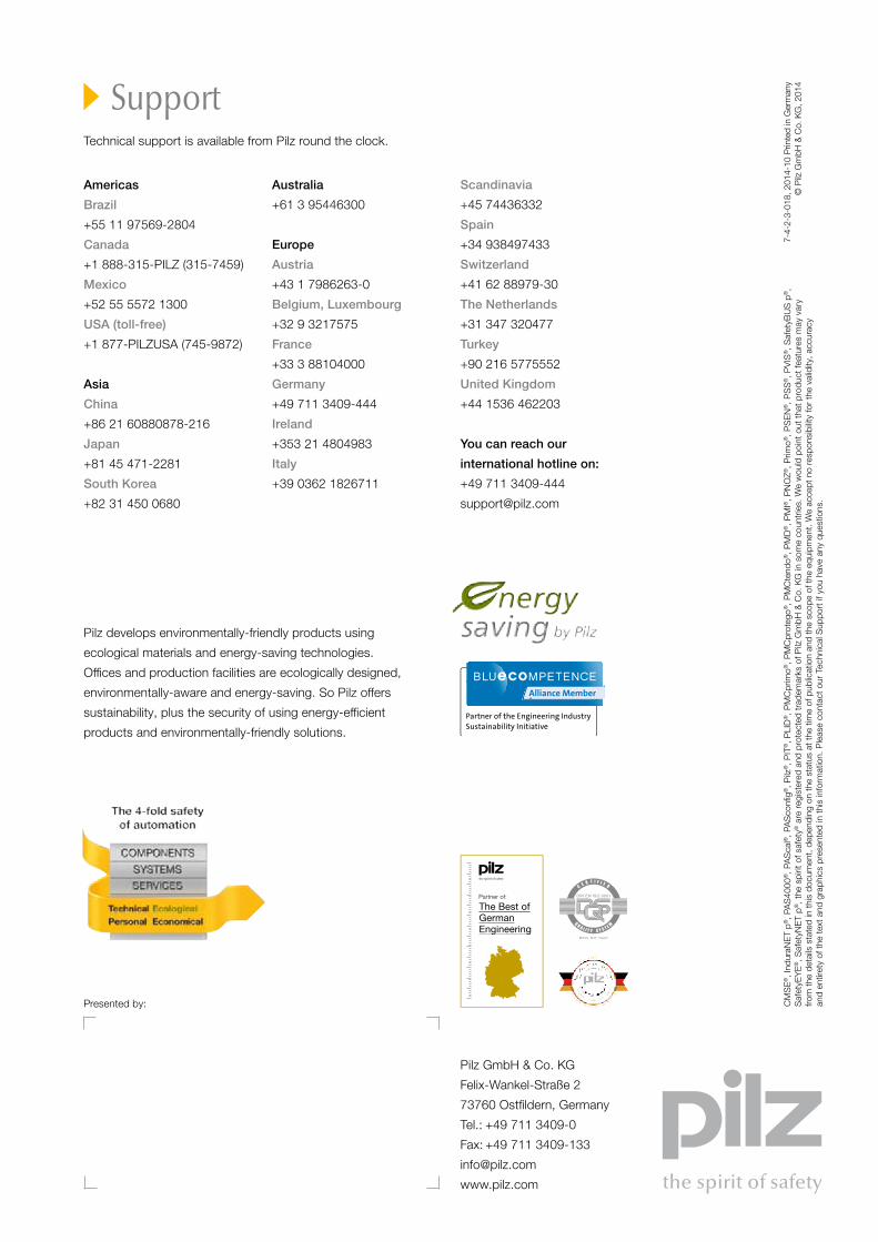
The Best of German Engineering
Partner of:
RUPilz RUS OOOUgreshskaya street, 2,bldg. 11, office 16 (1st floor)115088 MoskauRussian FederationTelephone: +7 495 665 4993E-Mail: [email protected]: www.pilzrussia.ru
SEPilz Skandinavien K/SSafe AutomationEnergigatan 10 B43437 KungsbackaSwedenTelephone: +46 300 13990Telefax: +46 300 30740E-Mail: [email protected]: www.pilz.se
TRPilz Emniyet Otomasyon Ürünleri ve Hizmetleri Tic. Ltd. Şti.Kayışdağı Mahallesi Dudullu Yolu Cad. Mecnun Sok. Duru Plaza No:7 34755 Ataşehir/İstanbul TurkeyTelephone: +90 216 5775550Telefax: +90 216 5775549E-Mail: [email protected]: www.pilz.com.tr
TWPilz Taiwan Ltd.7F.-3, No. 146, Songjiang Rd.Zhongshan Dist., Taipei City104, TaiwanTelephone: +886 2 2568 1680Telefax: +886 2 2568 1600E-Mail: [email protected]: www.pilz.tw
USPilz Automation Safety L.P.7150 Commerce BoulevardCantonMichigan 48187USATelephone: +1 734 354 0272Telefax: +1 734 354 3355E-Mail: [email protected]: www.pilz.us
SupportTechnical support is available from Pilz round the clock.
Americas
Brazil
+55 11 97569-2804
Canada
+1 888-315-PILZ (315-7459)
Mexico
+52 55 5572 1300
USA (toll-free)
+1 877-PILZUSA (745-9872)
Asia
China
+86 21 60880878-216
Japan
+81 45 471-2281
South Korea
+82 31 450 0680
Australia
+61 3 95446300
Europe
Austria
+43 1 7986263-0
Belgium, Luxembourg
+32 9 3217575
France
+33 3 88104000
Germany
+49 711 3409-444
Ireland
+353 21 4804983
Italy
+39 0362 1826711
Scandinavia
+45 74436332
Spain
+34 938497433
Switzerland
+41 62 88979-30
The Netherlands
+31 347 320477
Turkey
+90 216 5775552
United Kingdom
+44 1536 462203
You can reach our
international hotline on:
+49 711 3409-444
CM
SE®
, Ind
uraN
ET p
®, P
AS
4000
®, P
AS
cal®
, PA
Sco
nfig®
, Pilz
®, P
IT®, P
LID
®, P
MC
prim
o®, P
MC
prot
ego®
, PM
Cte
ndo®
, PM
D®, P
MI®
, PN
OZ®
, Prim
o®, P
SEN
®, P
SS
®, P
VIS
®, S
afet
yBU
S p
®,
Saf
etyE
YE®
, Saf
etyN
ET p
®, t
he s
pirit
of s
afet
y® a
re re
gist
ered
and
pro
tect
ed tr
adem
arks
of P
ilz G
mbH
& C
o. K
G in
som
e co
untr
ies.
We
wou
ld p
oint
out
that
pro
duct
feat
ures
may
var
y
from
the
deta
ils s
tate
d in
this
doc
umen
t, de
pend
ing
on th
e st
atus
at t
he ti
me
of p
ublic
atio
n an
d th
e sc
ope
of th
e eq
uipm
ent.
We
acce
pt n
o re
spon
sibi
lity
for
the
valid
ity, a
ccur
acy
an
d en
tiret
y of
the
text
and
gra
phic
s pr
esen
ted
in th
is in
form
atio
n. P
leas
e co
ntac
t our
Tec
hnic
al S
uppo
rt if
you
hav
e an
y qu
estio
ns.
Pilz develops environmentally-friendly products using
ecological materials and energy-saving technologies.
Offices and production facilities are ecologically designed,
environmentally-aware and energy-saving. So Pilz offers
sustainability, plus the security of using energy-efficient
products and environmentally-friendly solutions.
Pilz GmbH & Co. KG
Felix-Wankel-Straße 2
73760 Ostfildern, Germany
Tel.: +49 711 3409-0
Fax: +49 711 3409-133
www.pilz.com
Presented by:
7-4-
2-3-
018,
201
4-10
Prin
ted
in G
erm
any
© P
ilz G
mbH
& C
o. K
G, 2
014
Cont
rol t
echn
olog
y