Welcome to Control Technology Corporation’s QuickBuilder Motion Tutorial. The QuickBuilder Motion Module is intended for learners who have completed the QuickBuilder Basic Module. This module provides in-depth instruction for using QuickBuilder and the CTC Model 5300 for motion applications. This tutorial is designed to be completed in seven sessions. Four lab exercises are included to give you hands-on experience working with QuickBuilder to set up and execute several simple motion tasks. Completing the sections in the order provided is the best way to use this tutorial. The sessions include: Section 1: Motion Programming Overview; Section 2: Introduction to Motion Sequence Blocks, including Lab 1 ; Section 3: Using Variables in MSBs, including Lab 2 and 2a; Section 4: I/O Statements; Section 5: Program Flow; Section 6: Simple Motion, including Lab 3; and Section 7: Basic Pre-defined Variables
Motion Architecture – The Big PictureCTC’s Model 5300 uses a powerful object-oriented approach to solve motion control applications. This greatly simplifies application creation and maintenance. It also improves performance by off loading the demanding motion control tasks to specialized motion control processors on the 5300 Motion Modules.
Presenter
Presentation Notes
As you already learned in the Introduction to CTC’s Model 5300 Controller , the Model 5300 provides enhanced performance by design. By including a separate processor on I/O modules and motion cards, processing is distributed and the controller’s CPU is not forced to handle all tasks. These “smart” I/O modules and motion modules take the load off the controller’s processor, so performance is not compromised when an application has multiple axes or complex I/O.
The main components used in Model 5300 motion control are:
1.The Axis Module The physical Motion Module in the rack
2.The Axis Object The QuickBuilder Resource representing an axis on that physical module
3.The MSB The Motion Sequence Block containing one or more motionstatements that execute on the Axis Module’s CPU under the supervision of QuickStepTM on the main 5300 CPU
Presenter
Presentation Notes
First, let’s cover some terminology. The three main components in Model 5300 motion control are the Axis Module, the Axis Object, and the MSB. The Axis Module is the actual physical module you place in the Model 5300’s rack. These include – the M3-40A, M3-40B, and M3-40C cards. The M3-40A is a servo card, and the M3-40B and M3-40C are stepper cards. The Axis Object is the QuickBuilder resource that represents that axis. You will see it in the Resource Menu, with its correct name, for example labeled as an M3-40A card. This will be covered in depth later. The Motion Sequence Block or MSB is a standalone block of code that is part of your motion program. Your motion program may contain a few MSBs or many MSBs. Once you have created an MSB, you can use it over again in the same motion application or in new applications. This saves you time and effort, since you can create a library of these blocks to use over and over again as needed.
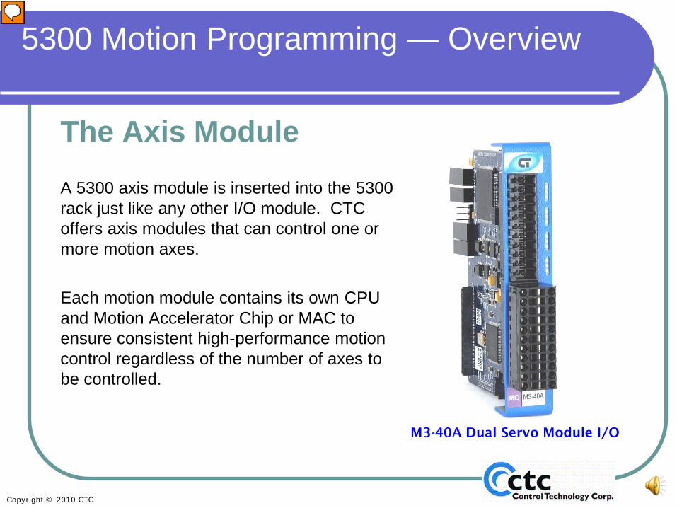
The Axis ModuleA 5300 axis module is inserted into the 5300 rack just like any other I/O module. CTC offers axis modules that can control one or more motion axes.
Each motion module contains its own CPU and Motion Accelerator Chip or MAC to ensure consistent high-performance motion control regardless of the number of axes to be controlled.
5300 Motion Programming — Overview
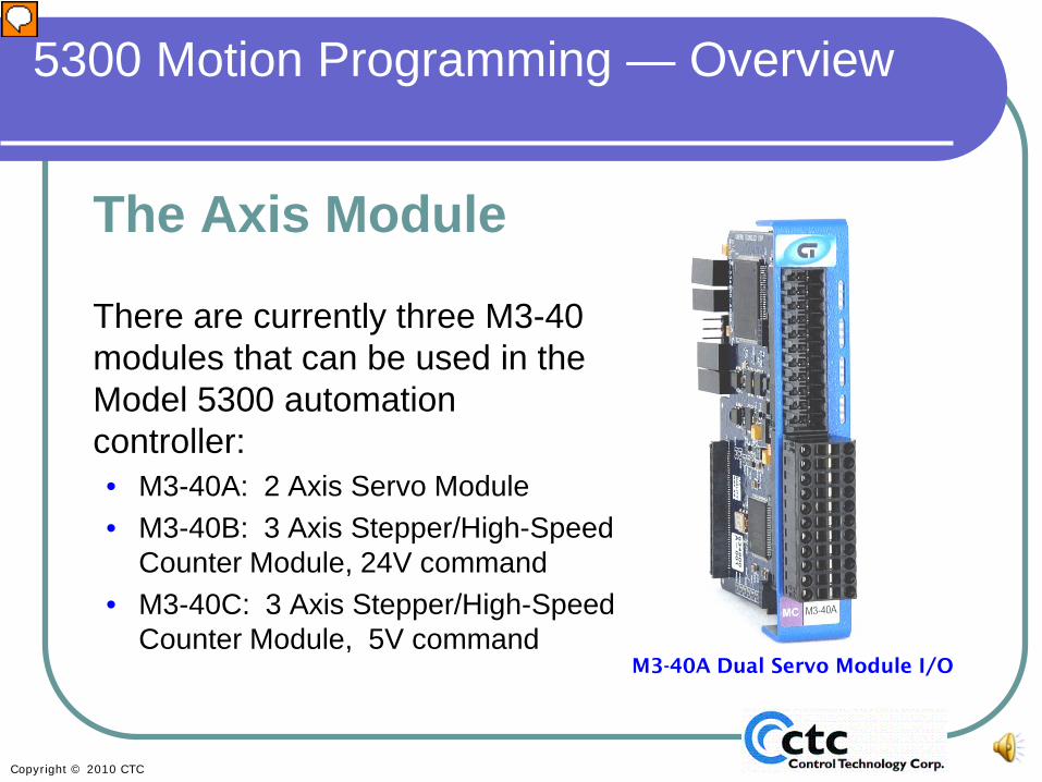
M3-40A Dual Servo Module I/O
Presenter
Presentation Notes
Here is a picture of the M3-40A module. When placed in the rack, each card can control one or two axes. Each module contains its own CPU and motion accelerator chip, which handles the PID loop for those axes. This ensures you can add more axes without slowing down the controller’s CPU. In some PLCs on the market, the processor does the work for all the axes, and when you add more axes, your loop time goes down and your performance is compromised. CTC’s motion cards have their own onboard CPU to prevent that from happening.
There are currently three M3-40 modules that can be used in the Model 5300 automation controller:• M3-40A: 2 Axis Servo Module• M3-40B: 3 Axis Stepper/High-Speed
A closer look reveals additional details about these motion cards. As mentioned earlier, the M3-40A is a 2-axis servo module. The M3-40B and M3-40C are stepper or high-speed counter modules. The M3-40B has a 24V step-and-direction output while the M3-40C has a 5V step and direction output . Choose the module based on the requirements of the drive you’re using. Also note that the M3-40B and M3-40C are listed as controlling three axes. With each of these modules, you can assign three axes, but you can only control two at a time. This is useful, for example, if you have X and Y axes, and a Z axis that moves only when you’re not moving one of the others. By eliminating the need to purchase an extra servo card, this “bonus” axis can greatly decrease the cost of your system. Tom Question: do we want to change our literature to say 2+ axes instead of 3?
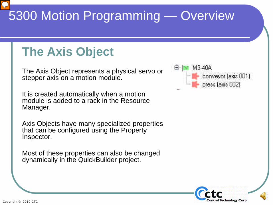
The Axis ObjectThe Axis Object represents a physical servo or stepper axis on a motion module.
It is created automatically when a motion module is added to a rack in the Resource Manager.
Axis Objects have many specialized properties that can be configured using the Property Inspector.
Most of these properties can also be changed dynamically in the QuickBuilder project.
5300 Motion Programming — Overview
Presenter
Presentation Notes
The Axis Object represents the physical servo or stepper axis in QuickBuilder. When you add a card to the rack, the card will show on the Resource Page as shown in the diagram. The cards become visible in QuickBuilder on the Resource Page . When the objects first appear on the Resource Page, you will see question marks instead of names such as those you see on this slide (conveyor and press). You name each axis yourself - replacing the question mark with a name of your choice - so that it makes sense for your application. The Axis objects you see on the Resource Page have specialized properties – many more than simple I/O. Most of them can be dynamically changed, for example, acceleration (acc) and deceleration (dec).
• Axis Objects have various inputs and outputs that control the servo (or stepper) and usually feedback signals that are used to monitor position.
• Using Motion Sequence Blocks (MSBs), you can command each axis to perform a sequence of motion statements.
Presenter
Presentation Notes
Each axis object or servo input includes dedicated inputs for encoder feedback. They also have programmable Inputs and Outputs that control the servo or stepper. Each axis has a maximum of five inputs and five outputs associated with it. These inputs are typically used for end-of-travel limits, home switches, registration inputs, and so on. The Outputs are typically used to enable drives, as fault signals to other devices, or for other uses for your process such as outputs to a labeler, or a knife for cut-to-length applications. MSBs are used to command each axis to perform the sequence of motions required by your application. Each MSB will typically include a number of motion statements.
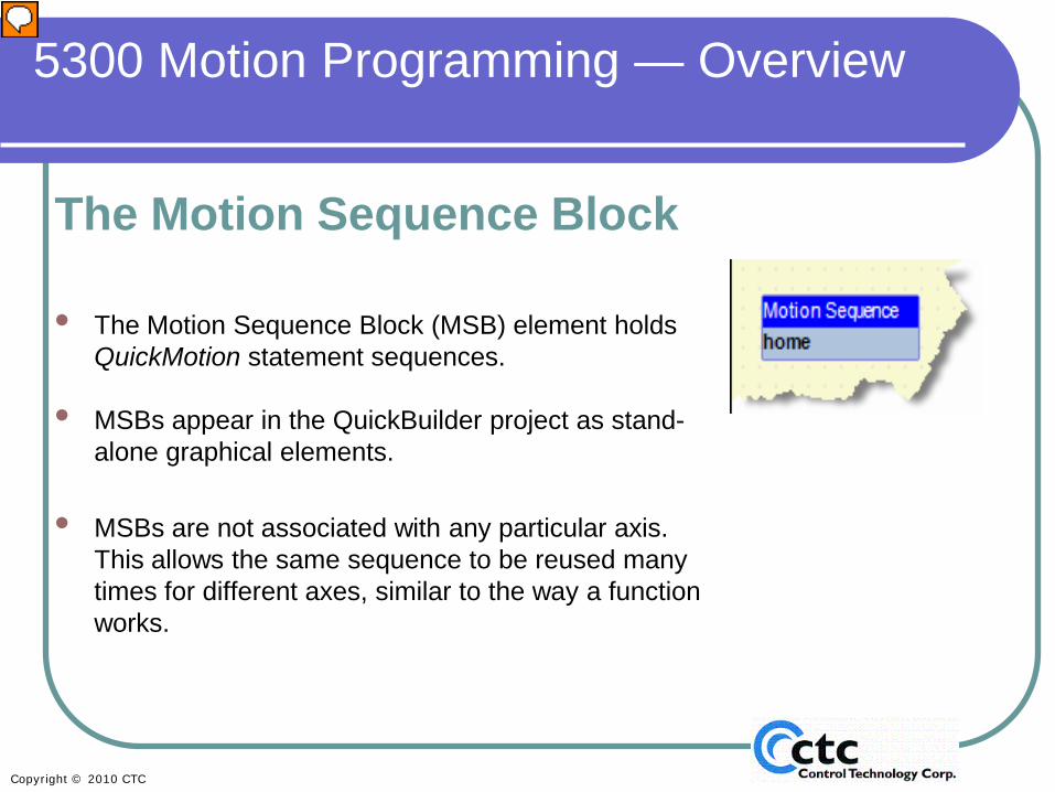
• The Motion Sequence Block (MSB) element holds QuickMotion statement sequences.
• MSBs appear in the QuickBuilder project as stand-alone graphical elements.
• MSBs are not associated with any particular axis. This allows the same sequence to be reused many times for different axes, similar to the way a function works.
5300 Motion Programming — Overview
Presenter
Presentation Notes
Let’s take a closer look at MSBs. MSBs appear as standalone graphical elements. The MSB acts like a task. In QuickBuilder, you don’t string MSBs together graphically. By naming each MSB in a way that makes sense to you, and arranging your MSBs on the screen, your program can become self-documented. You will be able to see quickly and easily the sequence of tasks that comprises your whole motion application as laid out logically by the MSBs it contains. A good thing to keep in mind is that MSBs are not associated with any particular axis. For example, if you have a standard homing sequence and you have 4 axes, you only have to create one MSB, perhaps called “home”. You can then just command Start Axis 1 home, Start Axis 2 home, Start Axis 3 home, Start Axis 4 home to use the same MSB on 4 different axis. You can even export that MSB to a library and use it on another machine. Place the MSBs you use routinely in your library, and access them for whatever machine you desire.
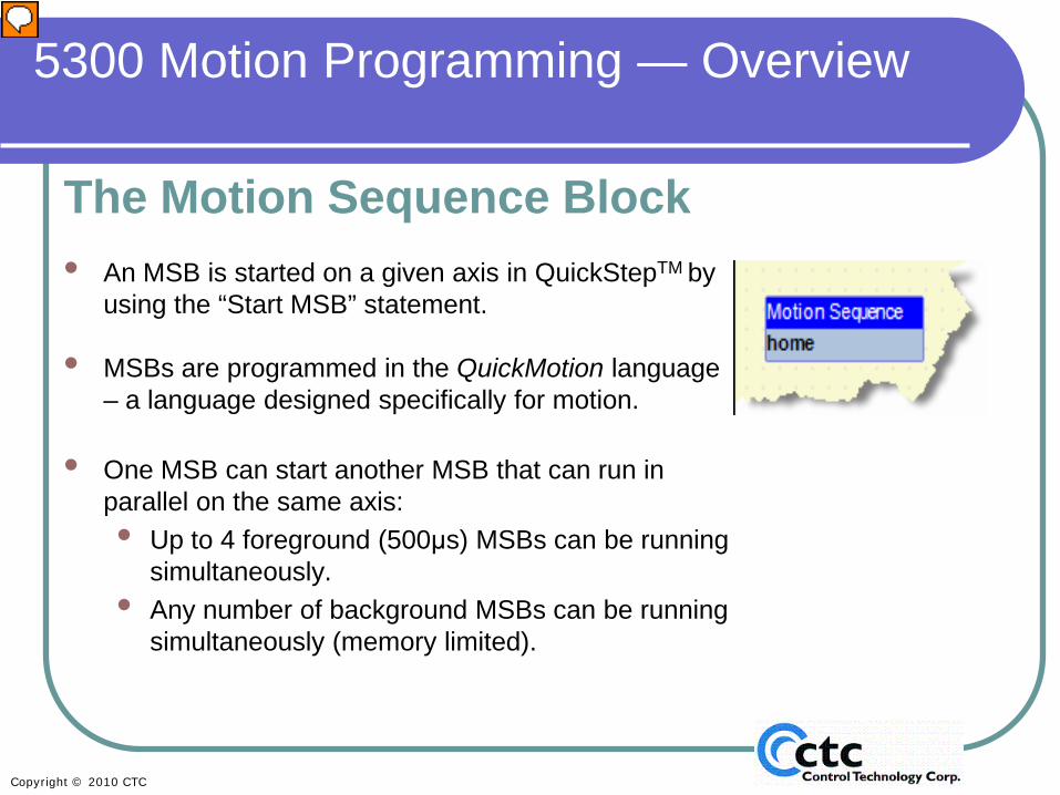
The Motion Sequence Block• An MSB is started on a given axis in QuickStepTM by
using the “Start MSB” statement.
• MSBs are programmed in the QuickMotion language – a language designed specifically for motion.
• One MSB can start another MSB that can run in parallel on the same axis:• Up to 4 foreground (500μs) MSBs can be running
simultaneously.• Any number of background MSBs can be running
simultaneously (memory limited).
5300 Motion Programming — Overview
Presenter
Presentation Notes
An MSB is started on a given axis using the Quickstep4 “Start MSB” statement. The motion commands themselves are contained within the MSB (and are programmed in QuickMotion). However, to start these motion commands, you must use the Quickstep4 “Start” command. Once you have started the first MSB, you can start another MSB from the first. You have the option of starting all your MSBs from Quickstep4 or starting only the first MSB from Quickstep4 . The approach you choose will depend on your application and personal preference. For example, if you're just doing motion here and there, and your motion is dependent on a lot of I/O from other cards, it may make more sense to start all your MSBs from Quickstep4 . Conversely if you are just doing simple, sequential moves, it may make more sense to have your first MSB started from Quickstep4 and the remaining MSBs started from that first MSB. MSBs can run either in the foreground (FG) or in the background (BG). You can have up to four MSBs running in the foreground. Foreground MSBs are guaranteed to run every 500 microseconds. Any number of background MSBs can be running simultaneously, only limited by the amount of memory you have available. As we begin to look at the commands used for MSBs we will indicate whether each command can be run in the foreground, background, or both.
There are only two Quickstep statements used to control motion on an axis in Quickstep4 (QS4):
start• Begins execution of the named Motion Sequence Block (MSB) on
the specified axis as a background (BG) or foreground (FG) MSB.
stop• Stops execution of all foreground and background MSBs
Presenter
Presentation Notes
Section 2: Introduction to Motion Sequence Blocks As mentioned earlier an MSB is started on a given axis using the Quickstep4 “Start MSB” statement. There are only two Quickstep statements used to control motion on an axis: Start and Stop. These commands are explained further on the next couple of slides.
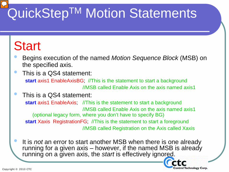
Start • Begins execution of the named Motion Sequence Block (MSB) on
the specified axis.• This is a QS4 statement:
start axis1 EnableAxisBG; //This is the statement to start a background //MSB called Enable Axis on the axis named axis1
• This is a QS4 statement:start axis1 EnableAxis; //This is the statement to start a background
//MSB called Enable Axis on the axis named axis1 (optional legacy form, where you don’t have to specify BG)
start Xaxis RegistrationFG; //This is the statement to start a foreground //MSB called Registration on the Axis called Xaxis
• It is not an error to start another MSB when there is one already running for a given axis – however, if the named MSB is already running on a given axis, the start is effectively ignored.
Presenter
Presentation Notes
The Quickstep4 Start command begins execution of the named MSB. For example, the first one listed on this slide is “start axis1 EnableAxisBG” For those of you already familiar with QuickBuilder, please note that you were not previously required to specify BG, and the program will still work without it. However, we recommend specifying BG, because then it’s explicit and obvious to anyone looking at the program (including you, when you look at the program again six months after you wrote it). Although you can have multiple MSBs running at the same time, you can only have one instance of any given MSB running at any one time. If you do command an MSB to start when it is already running on that axis, no fault will occur but the command will be ignored. Note that this is different than with tasks. You can have multiple instances of the same task running at the same time as discussed in the QuickBuilder Basic Module.
Stop Stops execution of foreground and background MSBs.
• stop axis1; //This is the statement to stop all MSBs on an axis from QS4
Presenter
Presentation Notes
Be very careful using the Stop command from Quickstep. This command stops ALL MSBs and disables the axes. If you’re just looking to stop motion, you stop it within the MSB for a controlled stop. You might use the Quickstep4 “Stop” statement when something has gone really wrong, but use this command with caution. This command is equivalent to when Perry White shouts “Stop the presses!” at The Daily Planet. Use this command with caution.
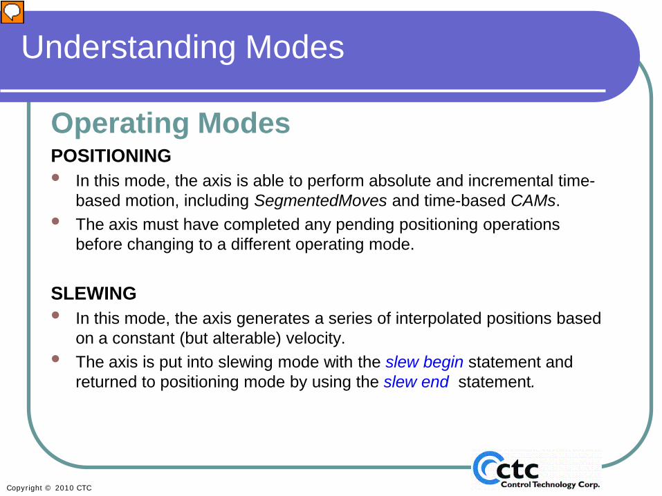
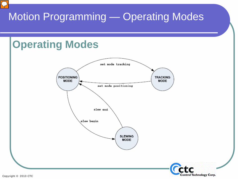
Operating ModesPOSITIONING• In this mode, the axis is able to perform absolute and incremental time-
based motion, including SegmentedMoves and time-based CAMs.• The axis must have completed any pending positioning operations
before changing to a different operating mode.
SLEWING• In this mode, the axis generates a series of interpolated positions based
on a constant (but alterable) velocity.• The axis is put into slewing mode with the slew begin statement and
returned to positioning mode by using the slew end statement.
Presenter
Presentation Notes
In QuickBuilder, there are three operating modes: positioning, slewing, and tracking. This section defines the modes for you. In the next section, we will go into the actual commands associated with each of these modes. Positioning mode allows you to do absolute and incremental time-based moves. Segmented moves and camming are also included in positioning mode. This is used for your typical point-to-point moves. Note that the axes must have completed any positioning moves before you can change to any other operating mode. Slewing is also known as jog mode or velocity mode. In slewing mode, you are able to specify the velocity at which you want the axis to move. An axis is put into or out of slewing mode using the “slew begin” and “slew end” commands, discussed further in this training module in Sections 2 and 6.
• The axis is able to perform position-tracking in this mode. This includes following and gearing.
• The axis must have completed all pending tracking operations before changing to a different operating mode.
Presenter
Presentation Notes
Tracking is also known as gearing or following mode. This allows one or more axes to follow a master axis and electronically gear to the master. For example, this is often used in large gantries where you have two motors mechanically linked for a gantry system and you need both motors to move at the same time. Another example is an in-feed conveyor, where you need to speed up the conveyor each time product enters the second conveyor to separate product.
In this overview of the three operating modes, you’ll notice that you can go from positioning mode directly to tracking or to slewing. But if you are in tracking mode, you first have to go back to positioning before you can go to slewing. Slew begin is not a valid command when you’re in tracking mode. These commands will be covered in depth in Section 2, Introduction to Motion Sequence Blocks.
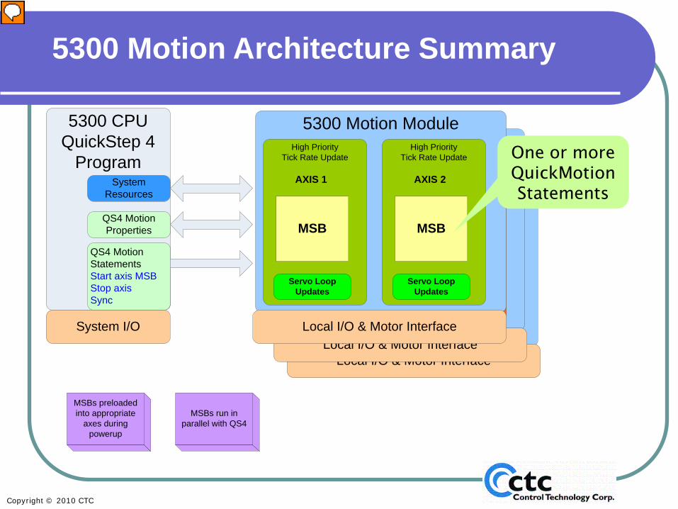
This slide offers a pictorial view of the Model 5300’s motion architecture: how the Controller and its CPU communicate with the Motion Module. This slide ends Section 1: Motion Programming Overview. Think about redrawing – maybe remove the little purple MSBs and leave them as notes; remove the sync; show the intercommunication between the controller and the motion card(s). Also somewhere add a slide that show the relationship between all the pieces of the QB suite – if that’s still the concept we’re working with – QuickBuilder and its components QuickStep4, QuickMotion, QuickView, QuickScope, etc???
This section covers statements that can be used within an MSB. These statements CANNOT be used in a QuickStep step!
• The MSB statement set was created to simplify the motion programming process and make powerful motion control applications accessible to a wide range of users.
• These statements are optimized for high-performance execution on the Model 5300 motion modules.
• In addition to the motion statement set, CTC provides over 100 pre-defined motion variables that can be used to simplify your application.
• Some important MSB variables are covered in a later slide.
Presenter
Presentation Notes
Section 2: Introduction to Motion Sequence Blocks (MSBs) Use this overview slide for all the MSB sections – e.g., camming, gearing In this section, we begin to talk about the statements that you use to program MSBs. For those of you who are already familiar with CTC controllers, keep in mind that MSBs cannot be used in Quickstep; QuickBuilder is currently only applicable for the CTC Model 5300. The MSB concept was developed to simplify motion programming and make more complex motion control applications accessible to a wider range of users. In addition to the motion statement set, CTC provides over 100 pre-defined motion variables that can be used to simplify your application. � Specific MSB variables will be covered in detail in later slides.
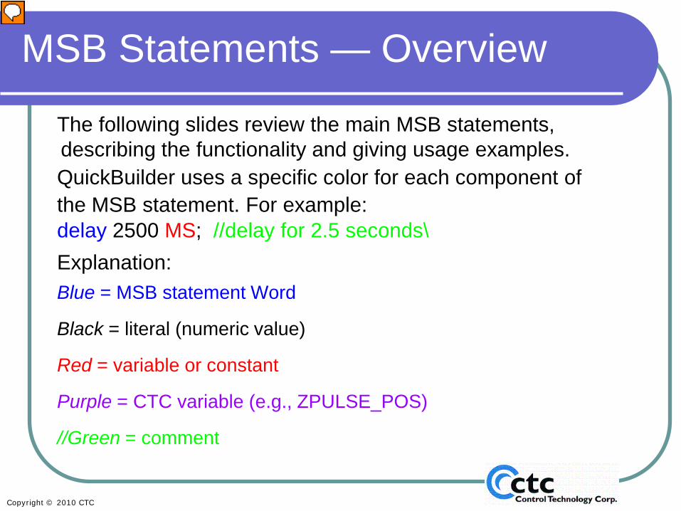
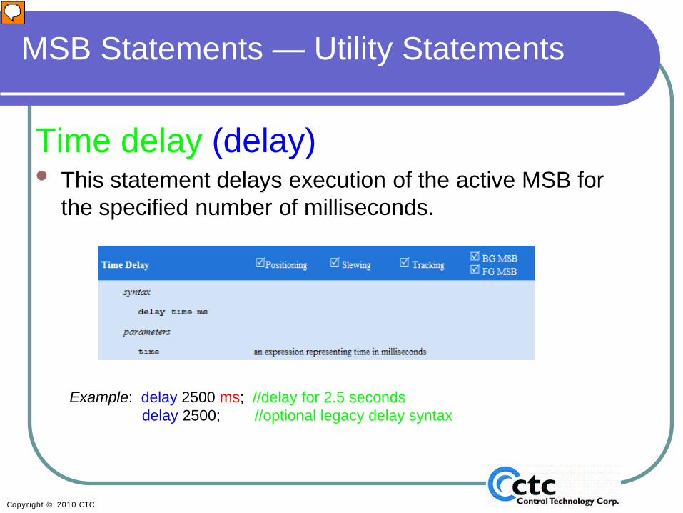
The following slides review the main MSB statements, describing the functionality and giving usage examples. QuickBuilder uses a specific color for each component of the MSB statement. For example:delay 2500 MS; //delay for 2.5 seconds\Explanation:Blue = MSB statement Word
Black = literal (numeric value)
Red = variable or constant
Purple = CTC variable (e.g., ZPULSE_POS)
//Green = comment
Presenter
Presentation Notes
The color coding you see in this slide is the same that you’ll see on the QuickBuilder screens. Just like in Quickstep4, commands, variables and constants are all case sensitive. Commands or MSB statements are always blue; Literals (numbers) are always black; Variables are colored red; CTC pre-defined variables are purple; and Comments are in green.
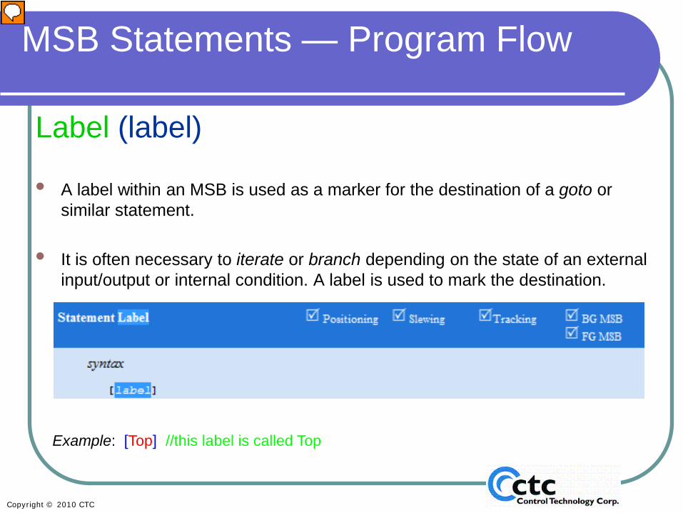
• A label within an MSB is used as a marker for the destination of a goto or similar statement.
• It is often necessary to iterate or branch depending on the state of an external input/output or internal condition. A label is used to mark the destination.
Example: [Top] //this label is called Top
Presenter
Presentation Notes
The first command we are looking at is “label.” A label is simply a destination, and this allows you to jump to different sections of an MSB. “Label” is always placed in square brackets and is the only command that is placed in square brackets. NOTE: All of the commands will indicate the mode they can be used in and if they can be used in a backgound (BG) or foreground (FG) MSB. You’ll notice a label can be used in all motion modes: positioning, slewing and tracking, and can be used in both BG and FG MSBs, since they are all checked.
• This statement causes program flow to jump/goto the specified label.
Example: goto Top; //jump to the MSB label called Top
Presenter
Presentation Notes
To get to a specific label (or section of your MSB), you use the “goto” command. In this example we’re telling the program to go to the top of the program, where “top” is the label we used in the last slide. NOTE: All the commands will indicate the mode they can be used in and if they can be used in a background (BG) or foreground (FG) MSB. You’ll notice the goto statement can be used in all motion modes: positioning, slewing and tracking, and can be used in both BG and FG MSBs, since they are all checked.
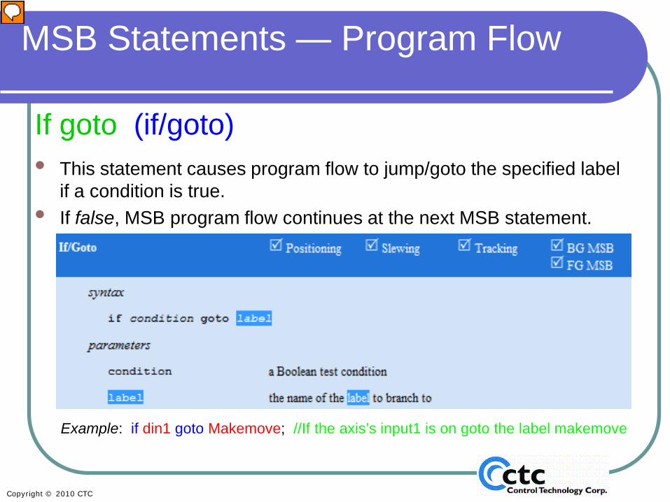
If goto (if/goto)• This statement causes program flow to jump/goto the specified label
if a condition is true. • If false, MSB program flow continues at the next MSB statement.
Example: if din1 goto Makemove; //If the axis’s input1 is on goto the label makemove
Presenter
Presentation Notes
“if/goto” is a conditional jump or goto statement. If the condition is true, the program will go to the specified label (or destination). If it is not true the MSB executes the next statement in the MSB. In this example, if digital input one (din1 is a predefined variable we will discuss in a later section) is on/true, the program will jump to the specified label/section of the statement. The label in this example is called “Makemove”.
Start (start)This statement activates another MSB.
• If the MSB is already active, this statement is effectively ignored.• Up to 4 foreground (FG) MSBs may be running simultaneously.• There is no logical limit to the number of active background (BG) MSBs.
Example: start PressCap FG; //start the MSB called PressCap and run as a foreground MSB
Presenter
Presentation Notes
The “start” command begins or activates another MSB on that same axis. In this example, we’re running an MSB on Axis 1. When you issue the start PressCAP FG command, the program will start the PressCap statement on axis 1 in the foreground. The discussion of foreground versus background MSBs can be found in Section 1, Motion Programming Overview.
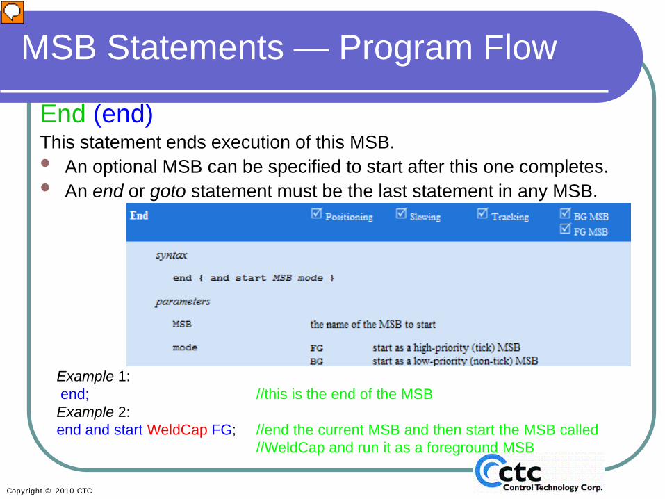
End (end)This statement ends execution of this MSB. • An optional MSB can be specified to start after this one completes.• An end or goto statement must be the last statement in any MSB.
Example 1:end; //this is the end of the MSBExample 2:end and start WeldCap FG; //end the current MSB and then start the MSB called
//WeldCap and run it as a foreground MSB
Presenter
Presentation Notes
The “end” command ends the execution of the MSB that issued that statement. In Example 1, we’re running the MSB called MakeMove. When the program sees the statement “end” it is stopped. There is also an optional command that allows you to end the currently running MSB and start a new one, called “end and start”. In Example 2, “end and start” stops the current MSB and starts a different MSB called “WeldCap” as a Foreground MSB. We recommend that in most cases you end an MSB, after it is complete. There are, however, a few cases where you will continuously run an MSB, for example, where you are using an asynchronous event to look for errors.
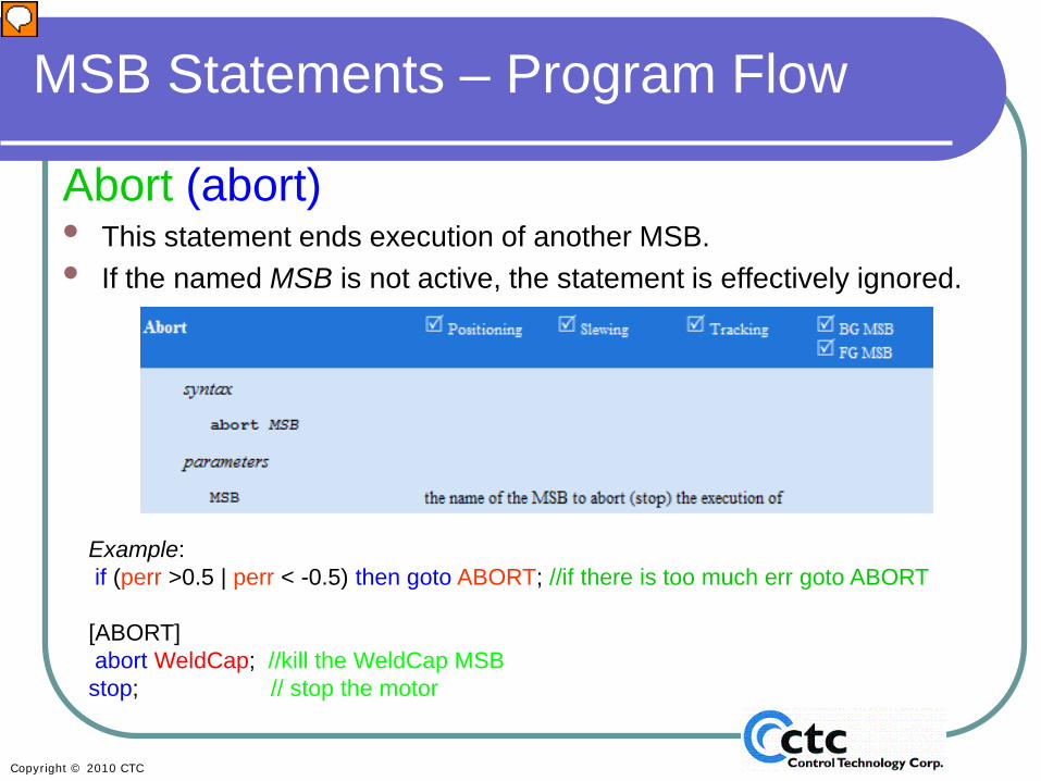
Abort (abort)• This statement ends execution of another MSB. • If the named MSB is not active, the statement is effectively ignored.
Example: if (perr >0.5 | perr < -0.5) then goto ABORT; //if there is too much err goto ABORT
[ABORT]abort WeldCap; //kill the WeldCap MSBstop; // stop the motor
Presenter
Presentation Notes
The abort statement ends the execution of a different MSB. While end allows you to stop the currently running MSB, you can also stop the execution of other MSBs running on the same axis using the abort command. This command would typically be used in MSBs that are looking for errors or faults. In the example, we are checking to see if the system variable “position error” (perr) exceeds +/- 0.5. If it does, we goto the ABORT label, abort the MSB called WeldCap, and stop motion on the motor.
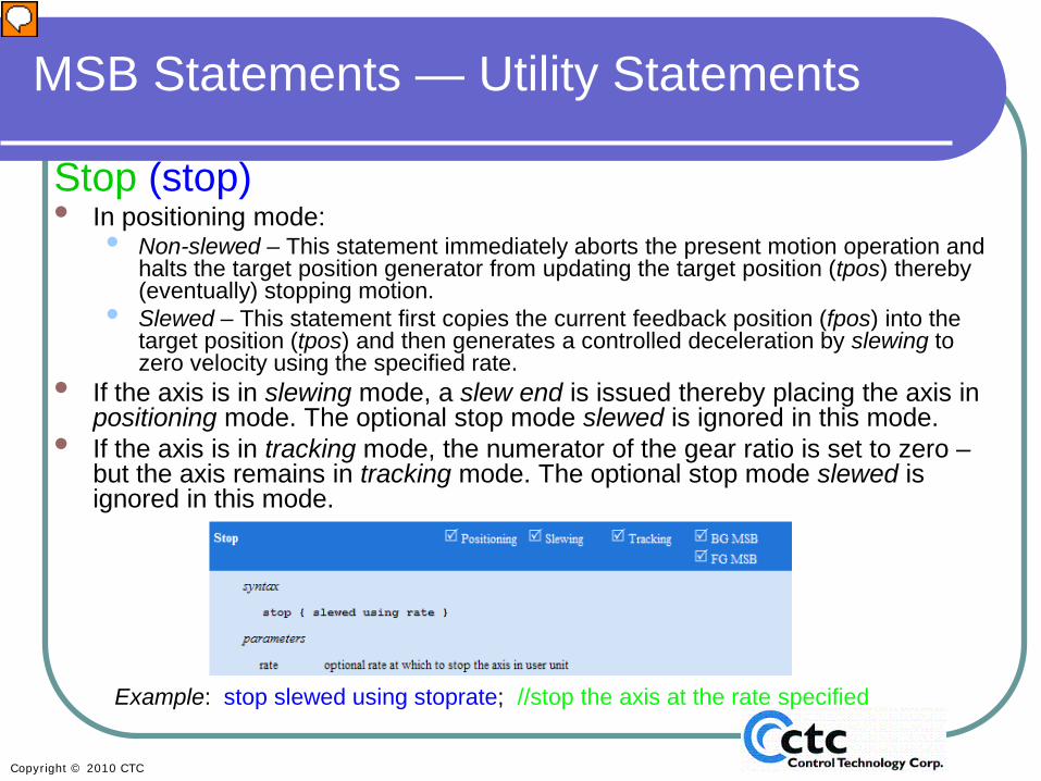
• Non-slewed – This statement immediately aborts the present motion operation and halts the target position generator from updating the target position (tpos) thereby (eventually) stopping motion.
• Slewed – This statement first copies the current feedback position (fpos) into the target position (tpos) and then generates a controlled deceleration by slewing to zero velocity using the specified rate.
• If the axis is in slewing mode, a slew end is issued thereby placing the axis in positioning mode. The optional stop mode slewed is ignored in this mode.
• If the axis is in tracking mode, the numerator of the gear ratio is set to zero –but the axis remains in tracking mode. The optional stop mode slewed is ignored in this mode.
Example: stop slewed using stoprate; //stop the axis at the rate specified
Presenter
Presentation Notes
The “stop” command performs different actions depending whether you are in positioning mode or slewing mode. Using the stop command in positioning mode: If you use the “stop” command, the target position generator stops the axis exactly in the position it was in when stop was issued. This usually builds in some position error, which may have adverse effects on your system. If you use the “stop slewed” command, you will stop the axis at a specified rate; this is also called a controlled or decelerated stop. Using the stop command in slewing mode (also known as jog mode): To stop motion on an axis in slewing mode, you typically use the commands “slew for”, “slew at 0” or “slew end” instead of “stop”, and we recommend that you use these command in slewing mode. A “stop” command in slewing mode acts as” slewend” and returns the axis to positioning mode. In tracking mode, the stop command causes the gear ratio to be set to zero, and the axis remains in tracking mode. Note: The optional “stop slewed using rate” command is only available in positioning mode and produces a standard stop in both slewing and tracking mode.
Enable/Disable Drive(drive enable) or (drive disable)
• Enables or disables the drive associated with the axis allowing motion to occur.
• Note: In some cases, the motor may slowly decelerate to zero velocity when disabling. This will be based on the drive/motor and how they are connected to the controller.
Example: drive enable; //enable the servo drive for this axis
Presenter
Presentation Notes
These commands allow you to enable or disable the drive. When a drive is enabled, the position loop and the target position are maintained using the programmed gains, meaning that holding torque will be maintained. If you have assigned an enable output via the property ‘drive enable’, that output will also be turned on when the “drive enable” statement is issued. “Drive disable” disables the drive, thereby removing holding torque from the motor and turning off the drive enable output if one is assigned. Whether you are using an output to enable your drive or not, you still need to use the drive enable command to maintain the holding torque and drive disable to release holding torque.
The three operating modes, positioning, slewing, and tracking, were defined in Session 1: Motion Programming Overview. We’ll now cover the commands for switching operating modes in greater depth.
Set Positioning Mode(set mode positioning)• Sets the operating mode of the axis to
positioning.• The axis must complete all pending
tracking operations before changing to a different operating mode.
Example: set mode positioning; //switch to positioning mode
Presenter
Presentation Notes
The “set mode positioning” command sets the operating mode of the axes to positioning mode and is used to move from tracking mode to positioning mode. By default the controller will power up with the axes in positioning mode. So this command is not required, except when returning from tracking or gearing mode. Note: This command is only allowed in tracking mode, and all tracking operations must be completed before changing modes.
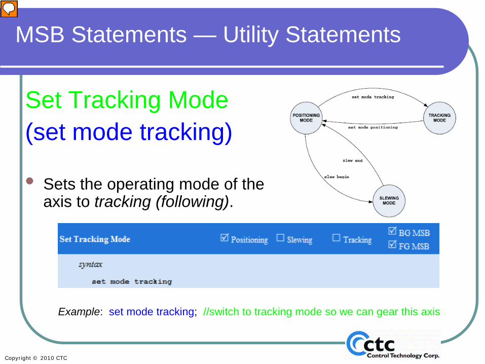
• Sets the operating mode of the axis to tracking (following).
Example: set mode tracking; //switch to tracking mode so we can gear this axis
Presenter
Presentation Notes
The “set mode tracking” is command allows you to put the system into tracking mode from positioning mode. The specific commands used in gearing mode will be covered in the QuickBuilder Gearing Module.
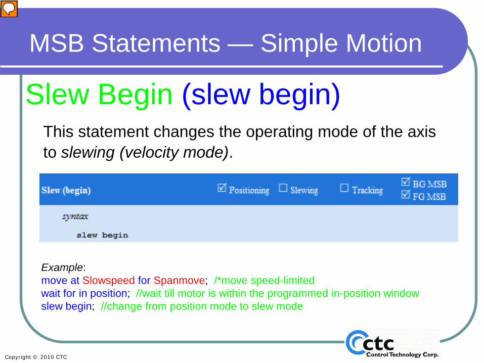
Slew Begin (slew begin)This statement changes the operating mode of the axis to slewing (velocity mode).
Example: slew begin; //change from position mode to slew mode
Presenter
Presentation Notes
“Slew begin” takes an axis from positioning mode into slewing (or jog) mode. The specific slew commands will be covered in the QuickBuilder Gearing Module.
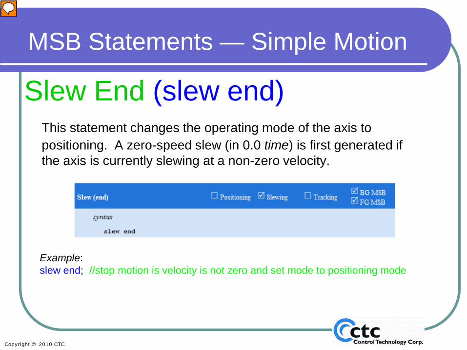
Slew End (slew end)This statement changes the operating mode of the axis to positioning. A zero-speed slew (in 0.0 time) is first generated if the axis is currently slewing at a non-zero velocity.
Example: slew end; //stop motion is velocity is not zero and set mode to positioning mode
Presenter
Presentation Notes
“Slew end” will immediately stop any motion on the axis and change the axis from slewing mode (or jog) mode to positioning mode. Note: this command is only allowed in Slewing mode. The specific slew commands will be covered in the QuickBuilder Gearing Module.
“Time delay” is used to delay execution of a command for a specified time frame. Any commands that follow a “delay” statement will be delayed. Note that the command “delay 2500 “is a legacy command, and while it works to accommodate older programs, we recommend that you use “delay 2500 ms” instead for clearer documentation and for the benefit of other users.
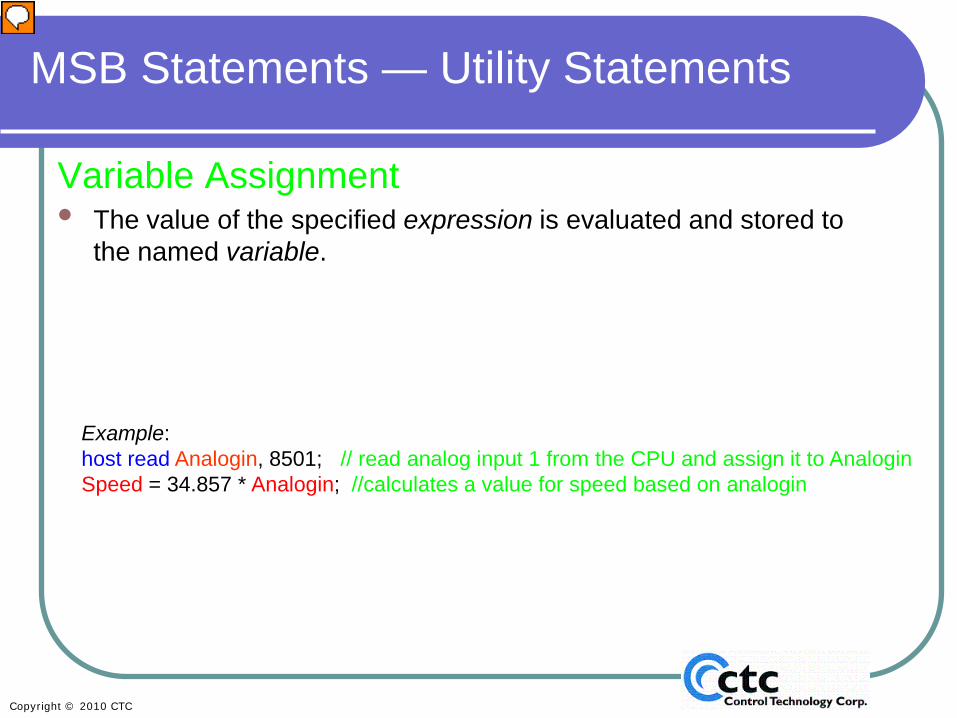
Variable Assignment• The value of the specified expression is evaluated and stored to
the named variable.
Example: host read Analogin, 8501; // read analog input 1 from the CPU and assign it to AnaloginSpeed = 34.857 * Analogin; //calculates a value for speed based on analogin
Presenter
Presentation Notes
Assignment is not a specific command, but rather a way to assign a new value to a variable, based on user input or a mathematical calculation . For example, you may have an analog input setting the speed of a servo motor. You will typically need to scale this analog input to relate to the speed output. In the example shown above, the variable “Speed” is being defined as the value obtained from an analog input and assigned to the variable “Analogin” and then multiplied by 34.857. Note: The host read command will be covered later in Section 3.
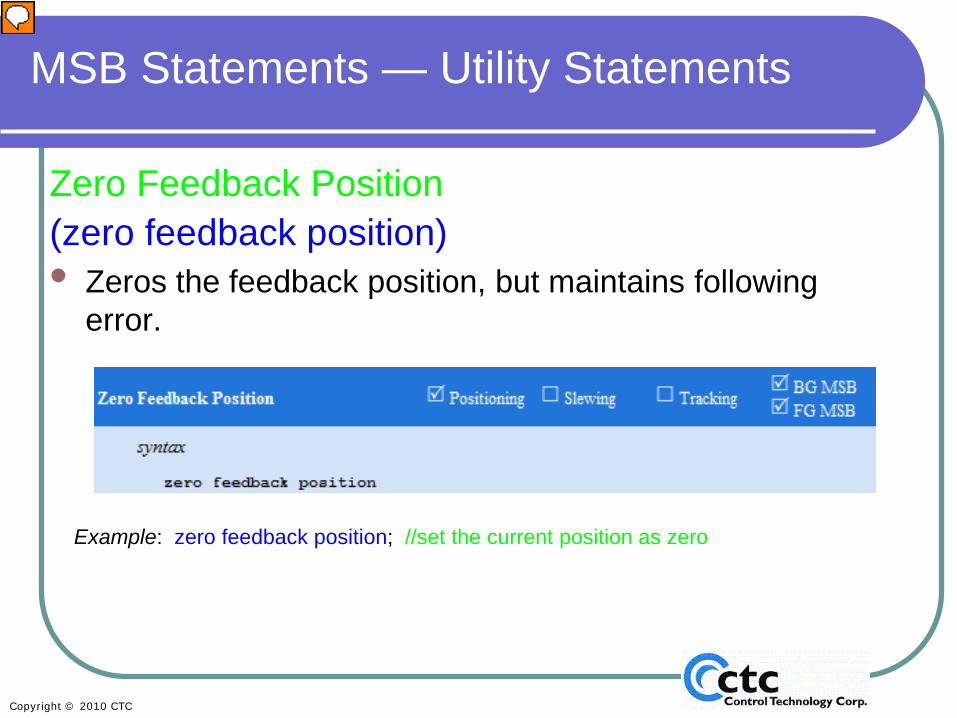
Zero Feedback Position (zero feedback position)• Zeros the feedback position, but maintains following
error.
Example: zero feedback position; //set the current position as zero
Presenter
Presentation Notes
The “zero feedback position” command will zero the current position of the motor and set it to zero. However, if there is any position error, that position error is maintained. Use the command “zero following error” (to be covered shortly) to eliminate the following error (which is simply the difference between your feedback position and the target position).
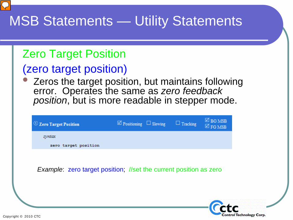
Zero Target Position(zero target position)• Zeros the target position, but maintains following
error. Operates the same as zero feedback position, but is more readable in stepper mode.
Example: zero target position; //set the current position as zero
Presenter
Presentation Notes
The “zero target position” statement operates the same way as “zero feedback”, but is typically used in stepper mode, since steppers don’t usually have feedback, they run open loop. “Zero target position” was created to make more sense for programming steppers.
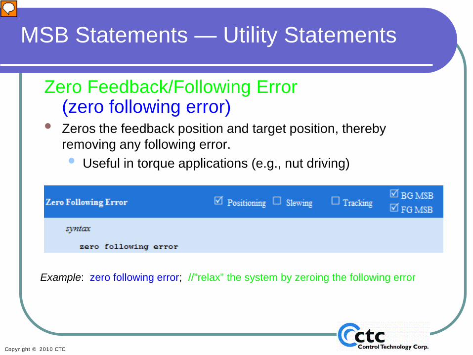
Zero Feedback/Following Error(zero following error)
• Zeros the feedback position and target position, thereby removing any following error.• Useful in torque applications (e.g., nut driving)
Example: zero following error; //”relax” the system by zeroing the following error
Presenter
Presentation Notes
The “zero following error” command allows you to wipe out or eliminate any accumulated position error (as opposed to the “zero feedback position” command, which doesn’t wipe out the error). This is useful if, for example, you are trying to torque a nut to a specific torque or you’re trying to “press” to a certain force, like snapping two parts together. Use these commands to eliminate the error that has built up.
• set target position & set feedback position set the position to a specific absolute value in user units.
• set target position counts & set feedback position counts set the position to a specific absolute value in counts.
• offset position & offset position counts modify the target and feedback positions simultaneously by adding the specified offset to both.
Note: Following error is maintained when these statements are executed.The axis must not be active (actively generating a target position by use of a move statement) when any of these statements are executed.
Set/Offset Target/Feedback Position (set/offset/target/feedback position)
Example: offset position counts 1100; // offsets both the target and feedback positions by 1100 counts
Presenter
Presentation Notes
This set of commands shown here allows you to set the offset or feedback position. These commands are typically used when you want to set your feedback or start position to a specific value. For example, you may home to a switch, but you may not want that home position to be considered zero. These commands allow you to set that position to a value that makes sense for your application. “set target position” (used for stepper applications) and “set feedback position” both set the target position to a specific value in user units, such as inches or centimeters. The “set target position counts” (again, used for steppers) and “set feedback position counts” do the same thing as “set target position” and “set feedback position”, but set them in encoder counts instead of user units. Similarly “offset position” modifies the position by adding an offset to the current position in user units, and “offset position counts” modifies the position by adding an offset to the current position in encoder counts. Following error is maintained in both these statements. CAUTION: Axes can’t be moving when these statements are used. Doing so will cause an axis fault.
You can check the fault status of any axis in the Control Status Window:
AFS:00 means that both axes do not have any faults.
The red AFS:F0 means there is a fault on the first axis.
Presenter
Presentation Notes
Now we’ll talk a bit about motion faults, before you proceed to do your first lab. QuickBuilder provides a Status/Control Window, where you can monitor each axis you have programmed and check for faults. In the lower right-hand corner of the Status/Control Window, the Axis Fault Status (AFS) is displayed. The top example on this slide shows a full Status/Control Window, with the Axis Fault Status in the lower right-hand corner — AFS:00. The number of digits indicates the number of axes (in this case, two) and 0 indicates there is no fault present. In this case, there are two axes and neither axis has a fault. If there were four axes and none of them had a fault, the Axis Fault Status would read AFS:0000. The second example shows only the bottom bar of the Status/Control Window. In this case the Axis Fault Status reads AFS:F0. This indicates that there are two axes, and that the first axis has a fault. Notice that the AFS indicator is displayed in red when a fault is present on one of the axes.
Clicking on the AFS (Axis fault Status) bring up any fault messages:
Clicking on <EXIT FAULT DISPLAY> gets you back to the standard Status/Control Window.
Presenter
Presentation Notes
If the AFS indicator is showing a fault, you can get more information by clicking directly on the AFS. This opens the Fault Display Screen, which contains information about any existing faults. In the example, AFS:0F00 there is a fault in the second axis, and it explains the fault: Following error limit reached. This particular error occurred because the target position – feedback position exceeds the perrlimit property set for axis 2. You can eliminate this from stopping your program by using on Asynchronous Event command to look for hard faults and setting up a fault routine to deal with too much position error. To return to the Status/Control Screen, click <EXIT FAULT DISPLAY>. Another useful tool for troubleshooting is the Watch Window, which is discussed in the next slide.
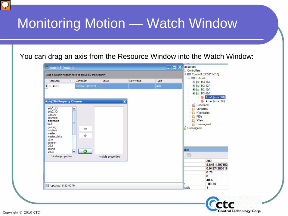
You can drag an axis from the Resource Window into the Watch Window:
Presenter
Presentation Notes
It’s always a good idea to monitor your program while it’s running — either in real time or when the program appears to have stopped. QuickBuilder allows you to monitor your servo parameters. A more detailed and basic discussion about the Watch Window can be found in the QuickBuilder Basic Module and as part of Lab. Exercise 1, where it’s covered in more detail. In the same way that QuickBuilder allows you to drag and drop any resource, you can drag an axis from the Resource Window into the Watch Window. In this slide, you see the Resource Window in the background. Our earlier example showed a problem with Axis 1. If you highlight Axis 1 and drag it into the Watch Window, the Property Window pops up. There you can choose which properties you wish to examine to further identify and isolate this fault.
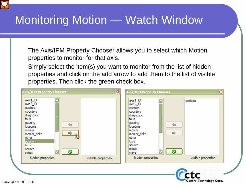
The Axis/IPM Property Chooser allows you to select which Motion properties to monitor for that axis.Simply select the item(s) you want to monitor from the list of hidden properties and click on the add arrow to add them to the list of visible properties. Then click the green check box.
Presenter
Presentation Notes
To choose the properties you wish to examine, you must change them from “hidden” to “visible.” To do so, highlight the property you want to add in the left pane and click the right arrow to select it for examination. You can highlight as many properties as are displayed, but you must highlight them one at a time, each time clicking the right arrow to make that property visible. To return a property in the right pane to “hidden,” highlight it and click the left arrow. When you have selected all the properties you wish to examine, click the green check mark. The next slide shows the result of those actions.
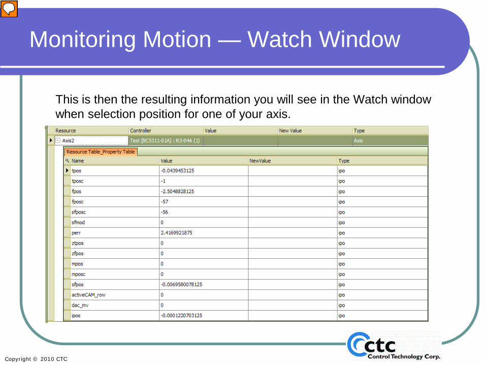
This is then the resulting information you will see in the Watch window when selection position for one of your axis.
Presenter
Presentation Notes
The Watch Window shows the parameters associated with each of the properties you made visible. It shows the property and its value. In this example, you are looking at the position properties. If the parameter is a read/write parameter, you may be able to change the value; if it’s a read-only parameter (for example, digital input 1) or a parameter that cannot be edited during run time, you will not be able to change the value in the Watch Window.
In Motion Lab 1, you will create a simple back-and-forth move to introduce the use of MSBs and Servo Tuning.
See Motion Lab 1 in the Motion Lab Manual.
Presenter
Presentation Notes
There’s no better way to learn than through direct, hands-on experience. Download the Motion Laboratory Workbook at XXXX. Proceed to Lab 1 to get some hands-on experience and a better understanding of how MSBs work. This lab also will help you become familiar with our servo tuning module and how to monitor servos. Helpful information on tuning is available in the online help. CAUTION: For your own safety, if at all possible, it is best to tune your motors while they’re not connected to a load.
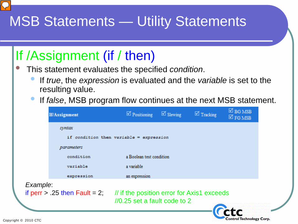
If /Assignment (if / then)• This statement evaluates the specified condition.
• If true, the expression is evaluated and the variable is set to the resulting value.
• If false, MSB program flow continues at the next MSB statement.
Example: if perr > .25 then Fault = 2; // if the position error for Axis1 exceeds
//0.25 set a fault code to 2
Presenter
Presentation Notes
Now that you have completed Motion Lab 1, you’re ready to return to Section 2 of this module to learn about additional MSB Utility Statements. In the beginning of this section , you learned about assignment, a way to assign a new value to a variable based on user input or a mathematical calculation. This was an unconditional assignment. With “if/assignment”, the assignment is only executed when a specific condition is met. In this example, we are setting a user variable called “fault” if the system variable “perr” (position error) is greater than .25.
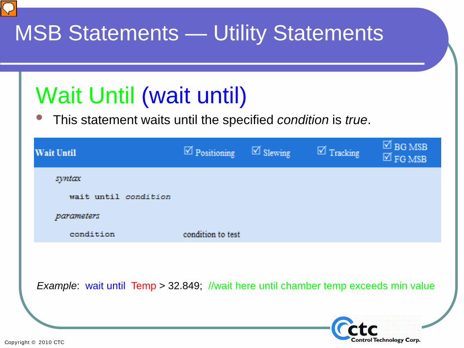
Wait Until (wait until)• This statement waits until the specified condition is true.
Example: wait until Temp > 32.849; //wait here until chamber temp exceeds min value
Presenter
Presentation Notes
The “wait until” statement suspends MSB operation until a specific condition is met. In other words, it causes the MSB to wait until the specified condition becomes true. This example shows a “wait until” statement that causes an MSB to begin only when the temperature exceeds 32.849. This slide ends Section 2: Introduction to MSBs. Section 3 focuses on how to use variables in MSBs.
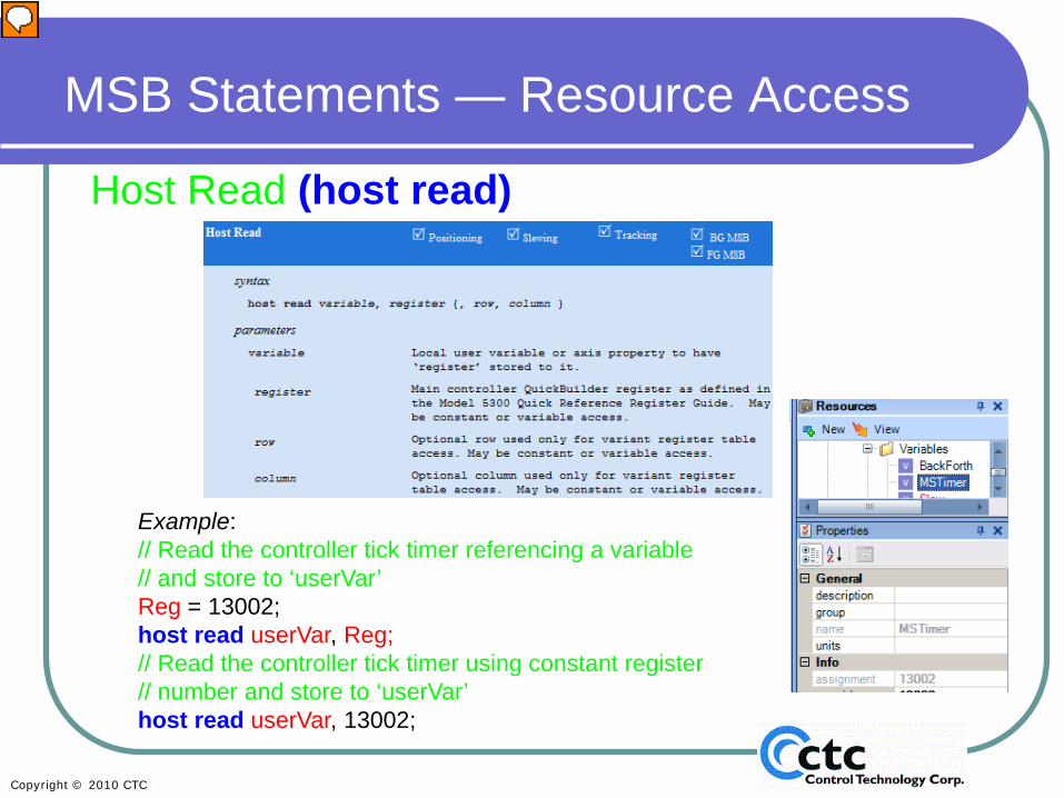
Host ReadPauses execution of the MSB while the contents of a QuickBuilder Register are retrieved from the main processor
• The register value is stored in the local “variable” or axis “property”.• The data type is automatically be converted to that of the local storage.• Integer-based registers, variant vectors, and tables are supported.• When reading a variant, one cell at a time in the table (if any) is read.• If no row or column is specified, 0 is assumed.
The next slide shows the syntax and an example of a host read statement.
Presenter
Presentation Notes
Section 3: Using Variables in Motion Sequence Blocks There are several ways to access the variables and resources used in the controller and on the servo card. In this section we’ll discuss the three methods you can use to communicate information between the processors on the controller and servo cards. Host read and write are typically the best way to handle data transfers. However, cbits are much faster and useful when you need to communicate between servo cards directly. We’ll discuss this further later. The “host read” command allows you to read any Quickstep4 variable or property in the Quickstep4 world from within an MSB. Basically the register value is stored as a local variable or axis property. This allows you to access any inputs, outputs, or variables that are assigned in the Quickstep4 world and read them into an MSB. You can access integer, float, or binary-based registers; you can also access vectors and tables.
Example:// Read the controller tick timer referencing a variable // and store to ‘userVar’Reg = 13002;host read userVar, Reg;// Read the controller tick timer using constant register // number and store to ‘userVar’host read userVar, 13002;
Presenter
Presentation Notes
In this example we are reading the Quickstep4 variable that has the assignment value 13002, and assigning that to a variable called “userVar”. The second example does the same thing as the first example, except we are using a literal (numeric value) to determine the variable we are reading from the Quickstep4 world. These are alternate but equivalent ways to use this command. This will go out and get the variable assigned to register 13002, in this case a millisecond timer. userVar will then be assigned to whatever the millisecond timer is at the moment that the host read command is executed. This is easy to test and try out. Since the timer values are always changing, you’ll easily see the results of this command.
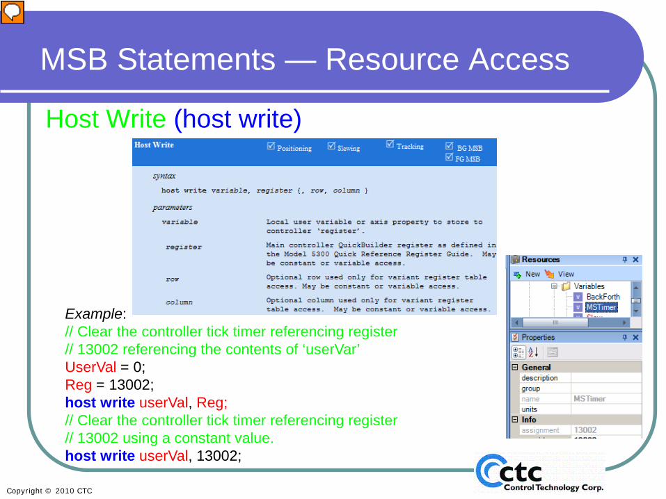
Host WritePauses execution of the MSB while a local “variable” or “axis property” is written to a QuickBuilder register on the main processor.
• The data type isautomatically be converted to that of the QuickBuilderregister, thus double will be converted to integer, etc.
• Integer-based registers, variant vectors, and tables are supported. • When reading a variant, one cell at a time in the table (if any) is read.• If no row or column is specified, 0 is assumed.
The next slide shows the syntax and an example of a host write statement.
Presenter
Presentation Notes
HostWrite allows an MSB to write information to the Quickstep4 world; it actually writes the values to a Quickstep4 variable or resource.
Example:// Clear the controller tick timer referencing register// 13002 referencing the contents of ‘userVar’UserVal = 0;Reg = 13002;host write userVal, Reg;// Clear the controller tick timer referencing register// 13002 using a constant value.host write userVal, 13002;
Presenter
Presentation Notes
In this example we are setting userVal to 0 and the register variable to 13002 (again, the millisecond timer). We are then setting the millisecond timer to 0 using the host write command and actually resetting the timer. It’s important to note that you cannot use a literal in the variable portion of the command. However, the register you are writing to on the controller can be either a literal or a variable as shown in the slide examples.
MSB Statements — VariablesUser Variables48 User Variables per axis
• double precision float• No need to define them• Accessible from both the MSBs for THAT axis and QS4.
QS4 example code: Axis1.x = DrillPosition; // set the variable X for Axis1 to DrillPositionAxis1.Speed = 5; // set the variable speed for Axis1 to 5start Axis1 MSB1; //start MSB1 on axis1
Axis1 MSB example code:Halfspd = Speed/2;move at Halfspd to x; /*Make a trap move to the DrillPosition specified
in the QS4 step at half speed */wait for inposition; //Wait for move to complete pulse 1 for 1000; // Turn the drill output on for 1 secmove at Speed to Home; // move to home at the speed specified above.
Presenter
Presentation Notes
Now we will examine variables more closely. In QuickBuilder, there are 48 user variables available per axis. They are all automatically double precision float (so you don’t need to define them like you do in Quickstep). When you type in variables, the compiler automatically defines them for you. These variables are accessible from both the MSB that is using it for that axis and from Quickstep. In the example code, you'll see that a variable called “x” in the MSB is being set for axis 1 to a variable called DrillPosition (a user-defined variable) and that the “speed” variable is set to 5. The variable “Half speed” is defined as “Speed/2. The effect of executing the Axis 1 MSB sample code is to move axis 1 at half speed (2.5) to drill position, wait for the axis to be in position, turn the drill output on for 1 second, and move to the home position at full speed (5). Now you’re ready for Motion Lab 2a.
Common Bits and VariablesCommon bits and common vars are used to communicate state
information and are much faster then standard variables:
a. between QuickMotion based modulesb. between QuickMotion and QuickStep 4c. between axes on a single module such as an M3-40A
• There are 256 common bits and 256 common vars. Common bits are Boolean, and common vars are bytes and, therefore, have values from 0 through 255.
• The common bits are shared globally among all QuickMotion modules as well as QuickStep 4. Any changes made to common bits are “seen” by all QuickMotion modules and the main CPU running QuickStep 4.
• The first 32 common vars are overlaid on top of the 256 common bits – changes made to a common var may alter up to 8 common bits.
• The remaining 224 common vars are module-local – changes are only seen local to the module. This is useful to communicate state information between axes on a two-axis QuickMotion module such as an M3-40A.
Presenter
Presentation Notes
Common bits (cbits) and variables (cvars) are much faster than standard variables and can be faster then host read and host write. The real advantage to common bits and vars is that you can communicate directly between two different servo cards without the need to send the information to the controller first. It’s important to note that cbits and the first 32 cvars are global to all axes and the controller, whereas axis variables are not. Common bits allow you to communicate directly between different cards on the same controller. When you are communicating to a standard variable, it can only be accessed or seen by Quickstep4 and only on the axis that is using that variable. So there is no way for another axis to see directly what those variables are set at. Common variables are only 8 bit and in most cases, common bits are going to be a quick way to give a status to another processor to say “I’ve faulted” or “I’m done moving.” Otherwise the Quickstep4 world has to read the variable and send it to another axis, which is often too slow for some applications. There are 250 common bits and common vars and they are common to Quickstep4 and all the axes. In other words, common bit 4 is the same on all axes in the system.
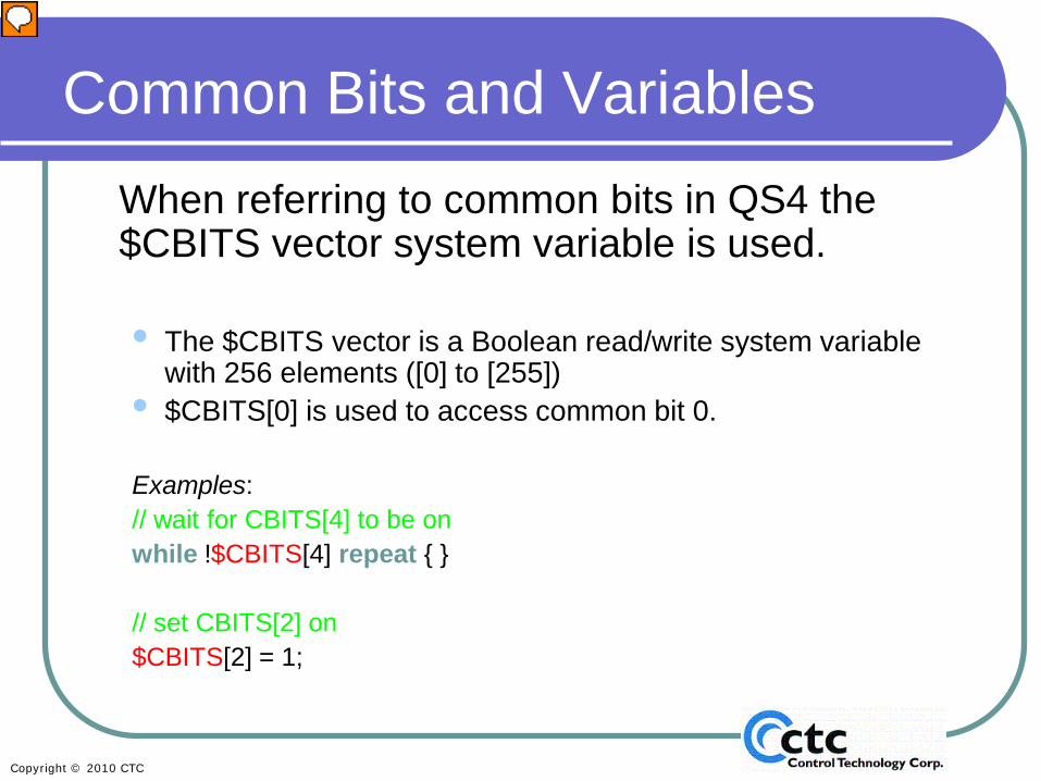
Common Bits and VariablesWhen referring to common bits in QS4 the $CBITS vector system variable is used.
• The $CBITS vector is a Boolean read/write system variable with 256 elements ([0] to [255])
• $CBITS[0] is used to access common bit 0.
Examples:// wait for CBITS[4] to be onwhile !$CBITS[4] repeat { }
// set CBITS[2] on$CBITS[2] = 1;
Presenter
Presentation Notes
If you’re referring to a common bit in the Quickstep4 world, you use the system variable called $CBITS and you pick which one of the common bits you want to access (0-255) and place that in the square brackets. In this example we are waiting for CBITS 4 to be “on”. Once it is on, we turn on CBITS 2 “on” (on=1=true)
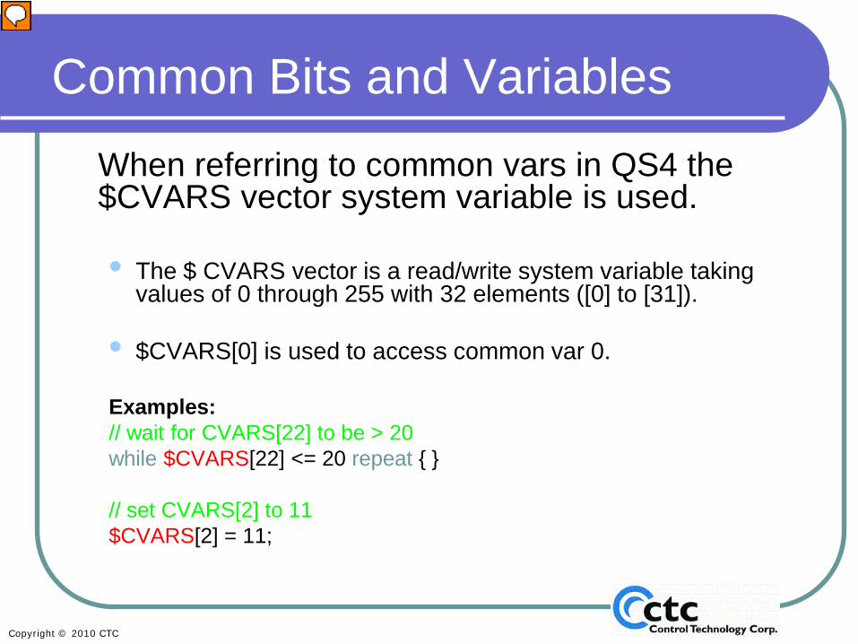
Common Bits and VariablesWhen referring to common vars in QS4 the $CVARS vector system variable is used.
• The $ CVARS vector is a read/write system variable taking values of 0 through 255 with 32 elements ([0] to [31]).
• $CVARS[0] is used to access common var 0.
Examples:// wait for CVARS[22] to be > 20while $CVARS[22] <= 20 repeat { }
// set CVARS[2] to 11$CVARS[2] = 11;
Presenter
Presentation Notes
When referring to common vars, the system variable is $CVARS and can have a value from 0 to 255, because it’s an 8-bit variable. There are up to 32 CVARS, and they are common to all the axes and Quickstep4 . In this example we are looking at CVAR 22 and waiting for it to be greater than 20; once that happens we set CVAR2 to a value of 11.
Set Common Bit (set common bit)Set Common Bit statement sets a common bit to a
specified state.
set common bit 45 true; //set common bit 45 to 1
Presenter
Presentation Notes
If you need to set a common bit in an MSB, you use the “set common bit” command. In this example we are setting CBIT 45 to 1 This command requires that you use “true” and “false” for the values 1 and 0 respectively.
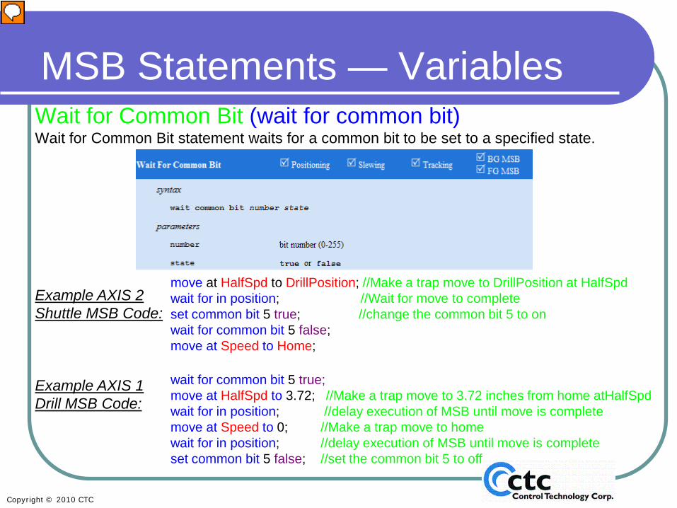
MSB Statements — VariablesWait for Common Bit (wait for common bit)Wait for Common Bit statement waits for a common bit to be set to a specified state.
move at HalfSpd to DrillPosition; //Make a trap move to DrillPosition at HalfSpdwait for in position; //Wait for move to completeset common bit 5 true; //change the common bit 5 to onwait for common bit 5 false;move at Speed to Home;
wait for common bit 5 true;move at HalfSpd to 3.72; //Make a trap move to 3.72 inches from home atHalfSpdwait for in position; //delay execution of MSB until move is completemove at Speed to 0; //Make a trap move to homewait for in position; //delay execution of MSB until move is complete set common bit 5 false; //set the common bit 5 to off
Example AXIS 2 Shuttle MSB Code:
Example AXIS 1 Drill MSB Code:
Presenter
Presentation Notes
If you are checking the status of a bit from within an MSB you use the “wait for common bit” command. In this example, we’re looking at the Axis 2 (shuttle) MSB code first. In the Axis 2 MSB the instruction is to move to a position and wait for that move to complete. When it’s completed, we set CBIT 5 to be true/1. Meanwhile the MSB code for Axis 1 (the drill), was waiting for Axis 2 to set common bit 5. When it does so, Axis 1 is instructed to move at half speed to its position, in order to drill a hole. The drill will then move back up, and as soon as that move is complete, it will set the common bit 5 back to false. This tells Axis 2, which has been waiting for Axis one to set common bit 5 to false, it can start up again. Without cbits, the Quickstep4 world would have to issue commands adding additional communication, which would take much longer.
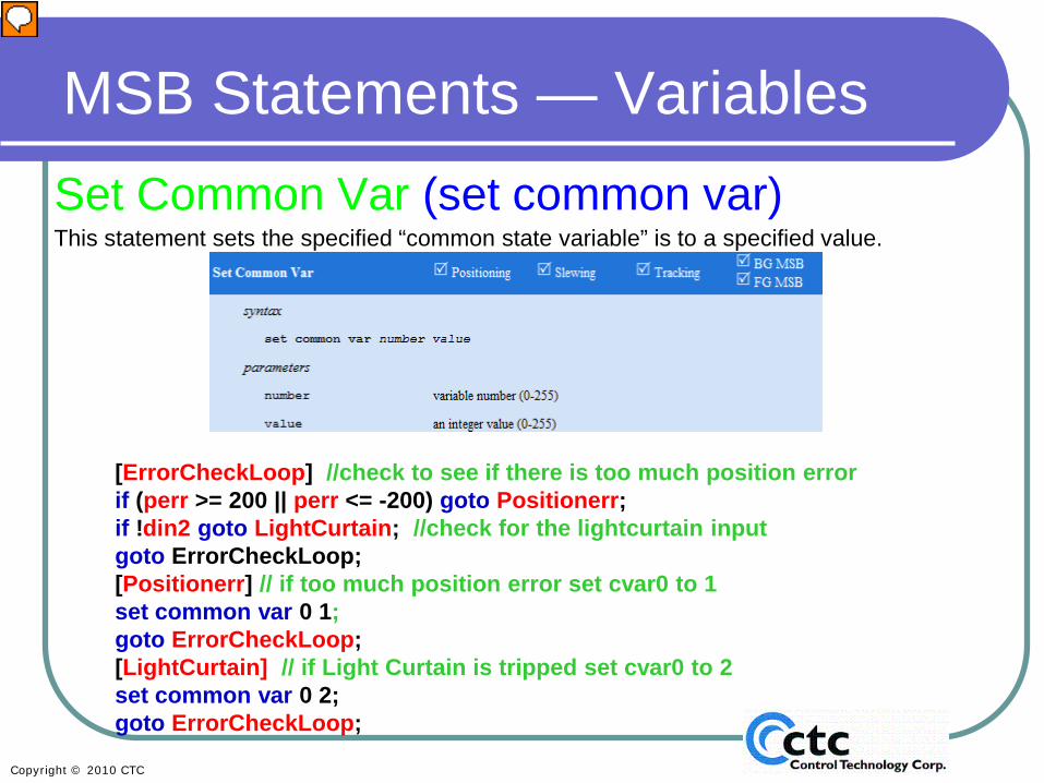
MSB Statements — VariablesSet Common Var (set common var)This statement sets the specified “common state variable” is to a specified value.
[ErrorCheckLoop] //check to see if there is too much position errorif (perr >= 200 || perr <= -200) goto Positionerr; if !din2 goto LightCurtain; //check for the lightcurtain inputgoto ErrorCheckLoop;[Positionerr] // if too much position error set cvar0 to 1set common var 0 1; goto ErrorCheckLoop;[LightCurtain] // if Light Curtain is tripped set cvar0 to 2set common var 0 2; goto ErrorCheckLoop;
Presenter
Presentation Notes
When you’re trying to set a common variable within an MSB, you use the “set common var” command. In this example an axis is running an MSB that does an error check for too much position error or a light curtain trip based on digital input 2 on the servo card. If too much position error is seen common var 0 (cvar0) is set to 1. If the light curtain is tripped it is set to 2. Any axis or the processor can then check the status of cvar0 to see if there is a problem on the axis running this MSB.
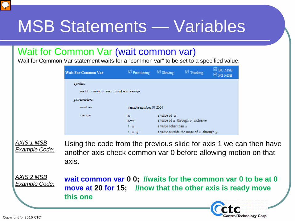
MSB Statements — VariablesWait for Common Var (wait common var)Wait for Common Var statement waits for a “common var” to be set to a specified value.
AXIS 1 MSB Example Code:
AXIS 2 MSB Example Code:
Using the code from the previous slide for axis 1 we can then have another axis check common var 0 before allowing motion on that axis.
wait common var 0 0; //waits for the common var 0 to be at 0move at 20 for 15; //now that the other axis is ready move this one
Presenter
Presentation Notes
The “wait for common var” command allows you to wait for a common var to be equal to a certain value before continuing execution of an MSB. In this example, we are assuming Axis 1 was using the code on the previous slide to check for errors. Axis 2 is then waiting for common var 0 to be equal to 0 (no errors), before the axis will move. This slide ends Section 3: Using Variables in Motion Sequence Blocks.
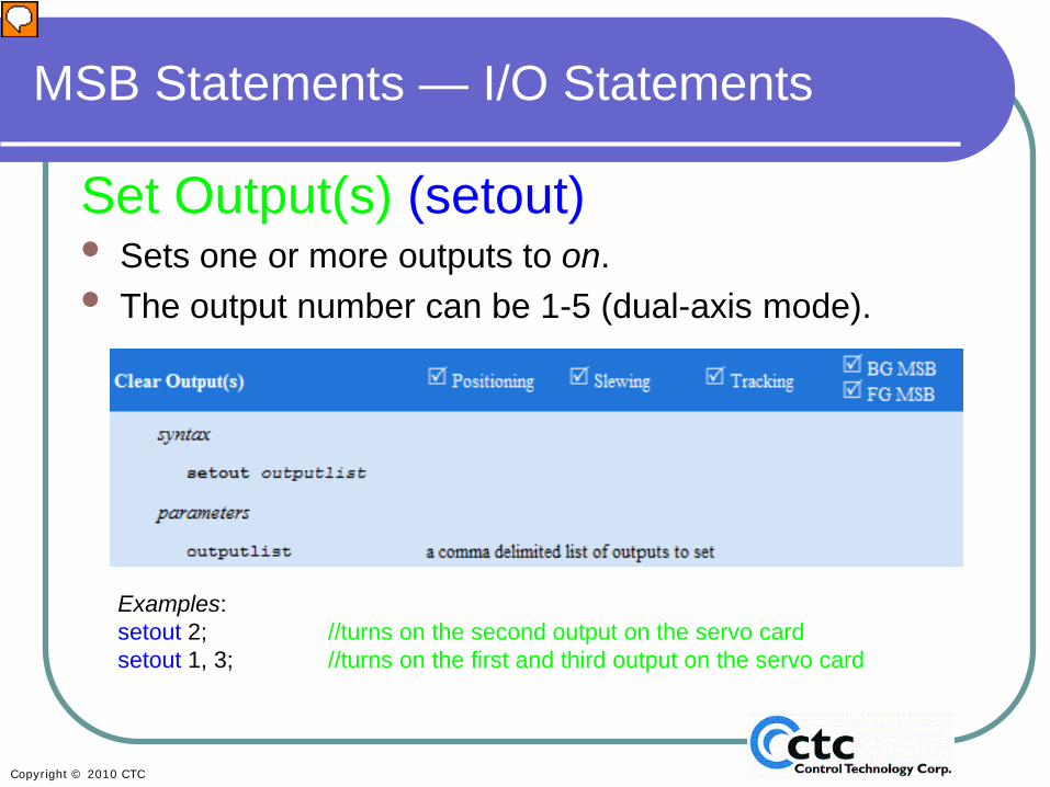
Set Output(s) (setout) • Sets one or more outputs to on.• The output number can be 1-5 (dual-axis mode).
Examples: setout 2; //turns on the second output on the servo cardsetout 1, 3; //turns on the first and third output on the servo card
Presenter
Presentation Notes
DAWN, KEVIN THE REFERENCE GUIDE HAS A MISTAKE IN THE TITLE HERE Section 4: I/O Statements This slide begins the section on Motion Sequence Block I/O statements. Here we will start with basic output statements, the first of which is the “set output” command. This command allows you to turn on the built-in outputs on your servo card. As you recall, each axis has five outputs associated with it. In the example, the “setout 2” command will turn on output 2. If you want to turn on multiple outputs, you can do that by comma delimiting the output numbers. The second example turns on outputs 1 and 3, by listing 1 and 3, separated by a comma.
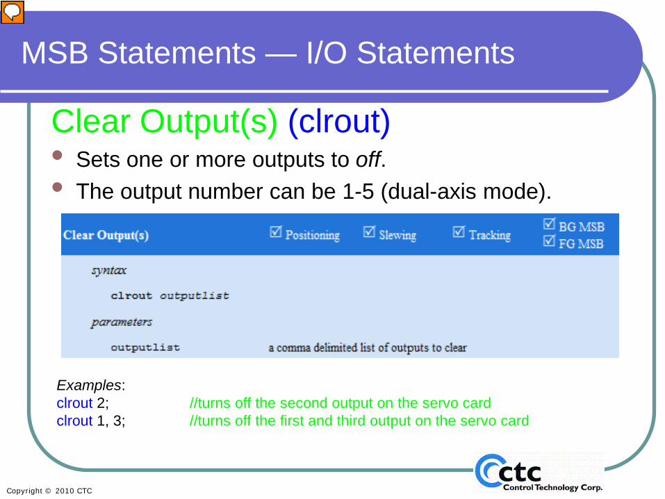
Clear Output(s) (clrout)• Sets one or more outputs to off.• The output number can be 1-5 (dual-axis mode).
Examples: clrout 2; //turns off the second output on the servo cardclrout 1, 3; //turns off the first and third output on the servo card
Presenter
Presentation Notes
The “clear outputs” command allows you to turn off any of the built-in servo outputs. In the example code, Clearout 2 turns off output 2 for that axis. Similar to setout, you can turn off multiple outputs by comma delimiting them. In the second example, the command turns off outputs 1 and 3 for that axis, again listing 1 and 3, separated by a comma.
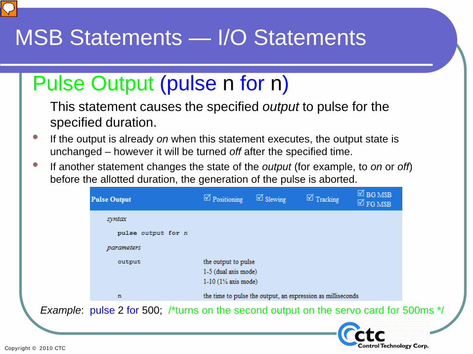
Pulse Output (pulse n for n)This statement causes the specified output to pulse for the specified duration.
• If the output is already on when this statement executes, the output state is unchanged – however it will be turned off after the specified time.
• If another statement changes the state of the output (for example, to on or off) before the allotted duration, the generation of the pulse is aborted.
Example: pulse 2 for 500; /*turns on the second output on the servo card for 500ms */
Presenter
Presentation Notes
The “pulse output” command allows you to turn an output on for a specified duration. This duration is specified in milliseconds. In this example, output 2 would be pulsed on for 500 milliseconds. The MSB would then proceed to the next command immediately. It would not wait 500 ms for the output to turn off (if you wanted it to wait you would have to use a delay command.) This is a very handy command for punch, labeling, and conveyor blow-off applications. This command allows you to pulse the output and then move on to take care of motion or deal with other inputs or outputs.
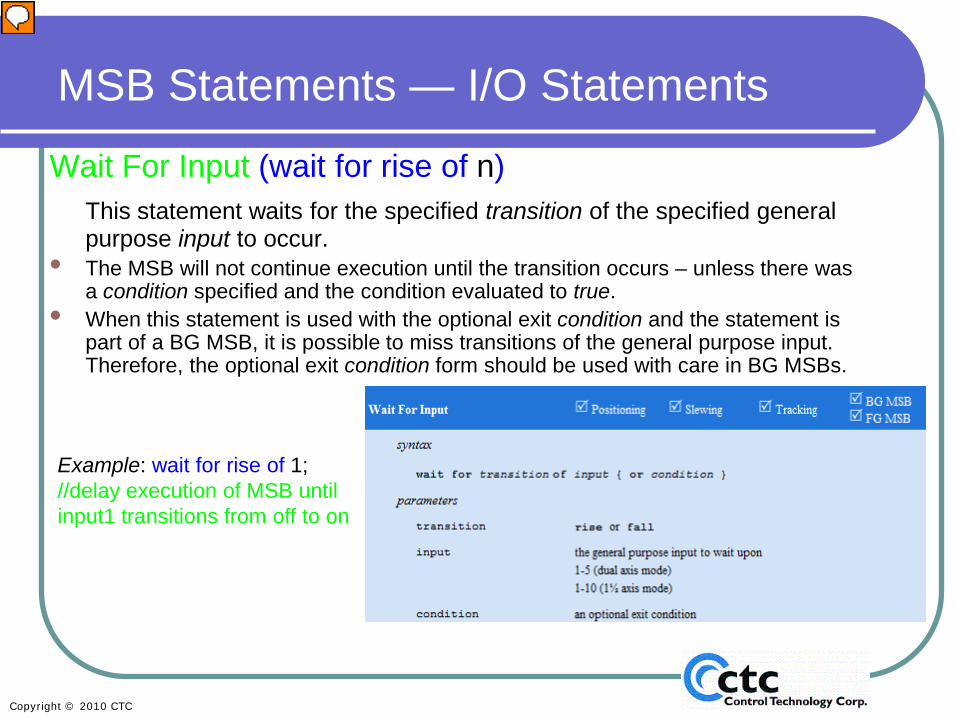
Wait For Input (wait for rise of n)This statement waits for the specified transition of the specified general purpose input to occur.
• The MSB will not continue execution until the transition occurs – unless there was a condition specified and the condition evaluated to true.
• When this statement is used with the optional exit condition and the statement is part of a BG MSB, it is possible to miss transitions of the general purpose input. Therefore, the optional exit condition form should be used with care in BG MSBs.
Example: wait for rise of 1; //delay execution of MSB until input1 transitions from off to on
Presenter
Presentation Notes
“Wait for Input” statements pause execution of an MSB until the appropriate state of an input occurs. You can wait for the “rise of” or the “fall of” a specified input. In this example we are waiting for the rise (transition from off to on) of input 1. This slide ends the discussion of basic output statements. Now you’re ready to work on Lab 3, Using Simple I/O.
In Motion Lab 3, you will modify Lab 2 to introduce the use of simple I/O.
See Lab 3 in the Motion Lab Manual.
Presenter
Presentation Notes
Refer to your Lab book to complete Motion Lab 3. This lab introduces you to the simple use of I/O. You can use Lab 2 and simply add the I/O usage to it. If you do not have an analog card, you can use variables in place of the analog input. Also, if you are doing this without a controller, skip the compile, download and debug sections.
Generate Pulses (generate output n rate n)This statement begins or ends generation of pulses using a specific output.If pulses are being generated on an output, then setout, clrout, and pulse output commands given to the same output have the following result:• setout - no pulse generation occurs; the output will be active• clrout - pulse generation occurs for non-zero freqs• pulse output - no pulse generation occurs until the pulse output completes
When a frequency of 0 is specified, no pulse generation occurs. This effectively turns the output back into a general-purpose output.The minimum frequency that can be generated is 1 Hz. The maximum frequency that can be generated is well over 500 kHz.
Now that we have covered basic I/O statements, we’ll discuss some advanced I/O starting with the command “generate pulses”. This command begins or ends the generation of pulses. So instead of just pulsing an output once, this command allows you to set up a pulse train. For example, this command would be useful to control a conveyor powered by an AC vector drive. It sets up a frequency of pulses to allow you to adjust the speed of the conveyor. The frequency range can be between 1Hz and 500 kHz. This is an inexpensive way to set the speed of the conveyor without the need to add a high-speed output or analog card. In this example we are setting Output 2 to generate a pulse rate of 500 Hz. Note: For safety - pay attention to the effect that “setout”, “clrout”, and “pulse output” have after this command has been executed.
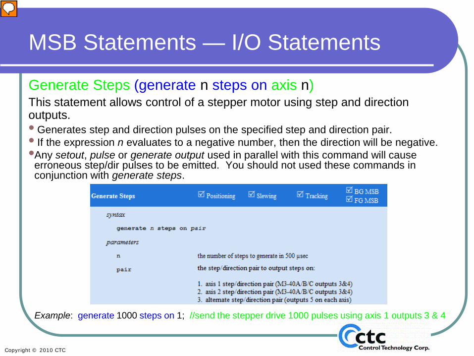
Generate Steps (generate n steps on axis n)This statement allows control of a stepper motor using step and direction outputs.• Generates step and direction pulses on the specified step and direction pair.• If the expression n evaluates to a negative number, then the direction will be negative.•Any setout, pulse or generate output used in parallel with this command will causeerroneous step/dir pulses to be emitted. You should not used these commands in conjunction with generate steps.
Example: generate 1000 steps on 1; //send the stepper drive 1000 pulses using axis 1 outputs 3 & 4
Presenter
Presentation Notes
The “generate steps” command allows you to control a stepper motor using step and direction outputs. You can choose which outputs are used for the 40A, 40B, or 40C cards by setting the pair. In the “step and direction pair” the “step” output defines how fast and how far the axis will move, and the “direction” output defines the direction in which the axis will move. How fast you send the “step” pulses determines the axis speed, and axis “direction” output determines if your motor moves clockwise or counterclockwise depending on the drive you are using. In this example, we will send 1000 steps to pair 1, which would be axis 1 outputs 3 and 4. NOTE: Take particular care using these commands of any place where you clear all the outputs as that will cause adverse effects to any generate step commands that are in process.
• On a M3-40A/B/C, (in stepper mode in the case of the M3-40A), the step and direction outputs are normally output on axis (TBx) pin pairs (15, 16).
• These cards also allow a third axis to be controlled by temporarily outputting step and direction pulses on TB1 pin 22 (step) and TB2 pin 22 (direction).
• To output on this alternate pair, issue the command generate alternate on. To output on the standard pair, issue the command generate alternate off.
• Be careful – only the destination of the step and direction signals change – to the axis that motion is being commanded on the primary axis (and thus updates it updates its idea of where the absolute stepper position is). Therefore, it is good practice to zero the target position (“zero target position”) before switching to or from this alternate mode.
Presenter
Presentation Notes
The “alternate stepper output” command allows you to access a third axis when one of the 2 axes on a M3-40A, B or C card are not in use. For step and direction, the M3-40A, B, and C cards have dedicated pins, usually pin pairs 15 and 16. As you may recall, these cards have a third or alternate axis, useful if you have an application with x/y axes and an independent z access that doesn’t run while the x/y are running. (for example a gantry or a drilling or punching application). The third axis can be controlled by temporarily outputting step and direction pulses on pin 22 of Terminal Block 1 (step) and pin 22 of Terminal Block 2 (direction). These outputs can only be used when one of the other axes is not generating pulses. The “generate alternate on” command is used to access these alternate step and direction outputs to control the third axis.
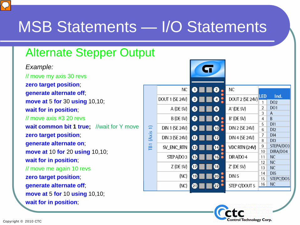
MSB Statements — I/O StatementsAlternate Stepper OutputExample:// move my axis 30 revszero target position;generate alternate off;move at 5 for 30 using 10,10;wait for in position;// move axis #3 20 revswait common bit 1 true; //wait for Y movezero target position;generate alternate on;move at 10 for 20 using 10,10;wait for in position;// move me again 10 revszero target position;generate alternate off;move at 5 for 10 using 10,10;wait for in position;
Presenter
Presentation Notes
In this example we are controlling axis (x) and the alternate axis (z). We are looking at an MSB in which the X axis is first making a move using the standard step and direction outputs, using pins 15 and 16. After that move is complete, the MSB zeroes the target position, turns the alternate step outputs on using pins 22 from both terminal block 1 and terminal block 2, and then makes a move on the third (Z) axis. Once that move is complete, the MSB zeroes the target position of both the axes (X and Z), turns the alternate step and direction outputs off, re-enabling the standard step and direction outputs again and makes a move on that axis. Note that the other axis (Y) could not be controlled by this MSB. This MSB is controlling X and Z. Chances are that the Y axis is doing a “start Y axis” and “make move” in another MSB. The code wait for common bit true would allow you to be certain that the Y axis had completed its move before allowing the Z axis to start its motion.
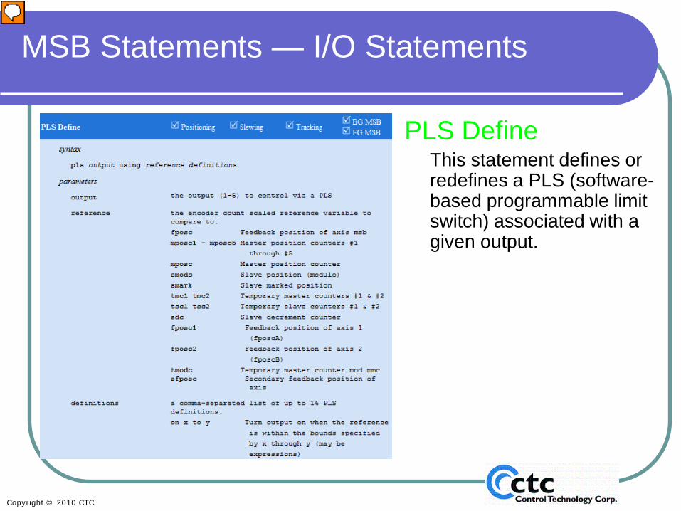
PLS DefineThis statement defines or redefines a PLS (software-based programmable limit switch) associated with a given output.
Presenter
Presentation Notes
Programmable Limit Switches: For those of you who are new to this, the “PLS Define” statement is basically a way to set up a software-based programmable limit switch . It allows you to quickly turn outputs on and off, based on a reference encoder. So it’s possible to have an output turn on specifically when an encoder is between the range of, for example, 200 and 1000 counts, and then turn on again for the range of 3000 and 3600 counts. The references from the encoder sources include the feedback from the axes that you’re using or feedback from another axis on the card or a master position. Other options are also listed on this slide.
This statement defines or redefines a PLS (software-based programmable limit switch) associated with a given output.
• A definition overwrites the previous definition for an output (if one was defined already)...
• When a PLS is defined/re-defined. it will be disabled and will not compute the state for the output.
• To enable a PLS after it is defined/re-defined, a pls on statement must be issued.
Presenter
Presentation Notes
When you use the PLS Define statement, you will override any previous PLS definitions that were entered. Note that a PLS statement must always be followed by an enable statement to turn it on, because the default is for the output to be disabled. An example is shown on the next slide.
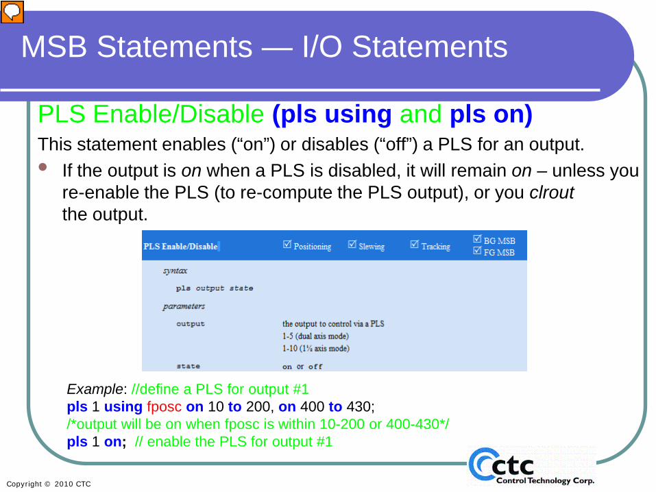
PLS Enable/Disable (pls using and pls on)This statement enables (“on”) or disables (“off”) a PLS for an output.• If the output is on when a PLS is disabled, it will remain on – unless you
re-enable the PLS (to re-compute the PLS output), or you clroutthe output.
Example: //define a PLS for output #1pls 1 using fposc on 10 to 200, on 400 to 430; /*output will be on when fposc is within 10-200 or 400-430*/pls 1 on; // enable the PLS for output #1
Presenter
Presentation Notes
In this example, we are defining a PLS for output 1 that turns on when the feedback position is between 10 and 200 counts and also when the feedback position is between 400 and 430 counts. Remember, once the PLS is defined, it must be enabled using the “pls on” statement. The “PLS off” statement will disable the PLS – or turn it off. However, disabling the PLS will NOT clear the output. So if the output is on when the PLS is disabled, it will remain ON. This is done for your convenience, but pay careful attention so that your program causes the actions you intend.
Counter Read Write/OffsetThese specialized forms of the assignment statement give read/write/offset access to the axis counters.
On the M3-40A, -40B and -40C, there are 8 counters/axes that accumulate off-to-on transitions of the following:
ctr[0] digital input #1ctr[1] digital input #2ctr[2] digital input #3ctr[3] digital input #4ctr[4] digital input #5ctr[5] ‘A’ channel input (non-quadrature)ctr[6] ‘B’ channel input (non-quadrature)ctr[7] ‘Z’ channel input (non-quadrature)
Presenter
Presentation Notes
This slide explains the first of the specialized input statements. You can set up to 5 high-speed counters per axis if you need encoder feedback (when you’re using a servo), or up to 8 high-speed counters if you don’t need encoder feedback. The inputs and the counter numbers associated with them are listed in the slide. The next slide shows how to use this command.
MSB Statements — I/O StatementsCounter Read Write/OffsetThese specialized forms of the assignment statement give read/write/offset
access to the axis counters.• The first form of the statement stores the current counter value in a variable.• The second form of the statement changes the current counter value.• The third form of the statement offsets the current counter value using +/- =.
Example: [top]// wait until input #1 riseswait for rise of 1; // get the current count value x = ctr[7];// accumulate Totalcounts = Totalcounts + x ;// offset so no counts are missedctr[7] -= x;goto top;
Presenter
Presentation Notes
Use the specialized forms of the assignment statement to access the axis counter. The first form of the statement, “ctr [n]” retrieves the current counter value and stores it in a variable. In this example, in the line “x=ctr7”, the MSB retrieves the current value on counter7 and stores it as variable x. The second form of the statement “ctr[n] = x” allows you to set the current counter value. In the example, counter 7 is re-set or set to a predetermined value “x”. This form is typically used to reset the counter. The third form allows you to offset the current counter value. In this example, total counts is offset by the variable “x”. You can offset the counter to the positive or negative. Overall this sample piece of code waits for input 1 to rise, then gets the current counter value, increments the total counts and offsets it by x, and then re-sets the counter. These statements allow you to accumulate counts and store them somewhere else, while still continuing to count.
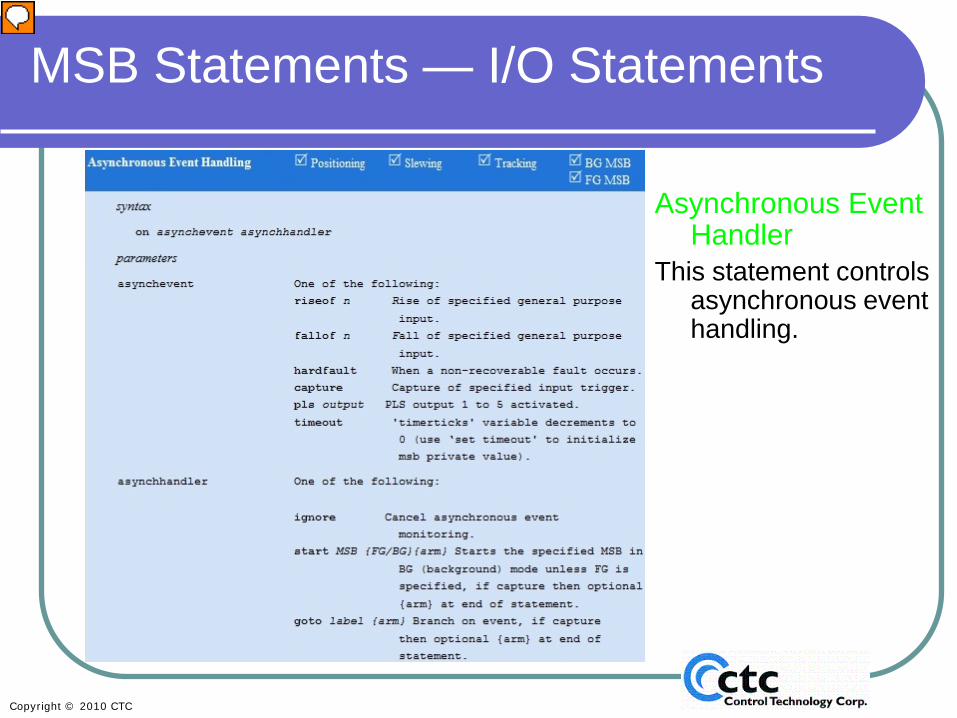
This statement controls asynchronous event handling.
Presenter
Presentation Notes
The asynchronous event handler allows you to handle events, whether they be inputs or hard faults. In this slide we are only discussing input events. In the Program Flow section we’ll discuss hard faults and other events such as programmable limit switch output and timeout options. Input events include the rise of an input, the fall of an input, or the capture of a specified input trigger. This command allows you to go to a specific label within the MSB (the same MSB in which the asynchronous event handler was enabled) or to start another MSB asynchronously, when any of the specified events occur. Once the asynchronous event is defined, it will watch for the event no matter what else is happening in that MSB for as long as the MSB is active (in other words, has not encountered an end statement). Once you set up an asynchronous event, you can cancel the event scan using an ignore statement.
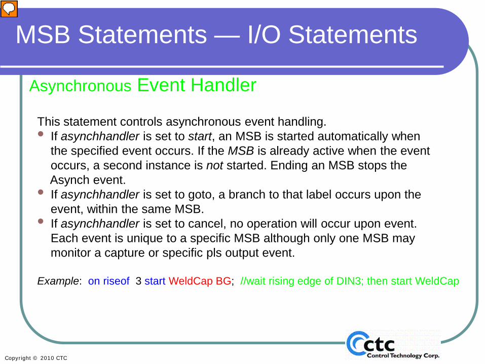
This statement controls asynchronous event handling.• If asynchhandler is set to start, an MSB is started automatically when
the specified event occurs. If the MSB is already active when the eventoccurs, a second instance is not started. Ending an MSB stops theAsynch event.
• If asynchhandler is set to goto, a branch to that label occurs upon theevent, within the same MSB.
• If asynchhandler is set to cancel, no operation will occur upon event.Each event is unique to a specific MSB although only one MSB maymonitor a capture or specific pls output event.
Example: on riseof 3 start WeldCap BG; //wait rising edge of DIN3; then start WeldCap
Presenter
Presentation Notes
If the Asynchronous Event Handler is set to start an MSB, the MSB is started whenever the event occurs. If that MSB is already active, a second instance is not started (it will be ignored). If the Asynchronous Event Handler is set to “goto”, the event will cause a branch to a label within that same MSB. If the MSB in which the Asynchronous Event Handler is coded is not active, the event handler also will not be active. Typically Asynchronous Event Handlers are used for error handling or to start a new MSB that initiates a movement or a cam. In this example, an Asynchronous Event Handler is set up to start an MSB called WeldCap as a background MSB, when input 3 transitions from off to on. If you start another MSB with this handler, the existing MSB will continue to run, whereas if you use a “goto” and create a branch it affects only that MSB and causes a jump to wherever the goto statement points. You would typically use a goto if you are using an Asynchronous Event Handler for error handling.
This statement controls asynchronous event handling.
Presenter
Presentation Notes
This slide begins Section 5: Program Flow. We will begin the discussion of Program Flow by continuing our look at the Asynchronous Event Handler. We‘ve already discussed using the Asynchronous Event Handler to cause a branch (with a “goto”) or start another MSB based on input events (rise of, fall of, or capture). We are now going to look at the other conditional events that can cause a branch or start another MSB. The Asynchronous Event Handler allows you to handle events, whether they be inputs or hard faults. Now we will discuss using the Asynchronous Event Handler in the event of hard faults and other items, such as PLS outputs and timeout options. The Asynchronous Event Handler can trigger a “start MSB” or “goto” when a hard fault occurs, when we see that a capture has occurred on a specified input trigger, when one of the PLS outputs are activated, or when a timeout occurs.
Asynchronous Event HandlerThis statement controls asynchronous event handling.• If asynchhandler is set to start, an MSB is started automatically when
the specified event occurs. If the MSB is already active when the eventoccurs, a second instance is not started. Ending an MSB stops theAsynch event.
• If asynchhandler is set to goto, a branch to that label occurs upon theevent, within the same MSB.
• If asynchhandler is set to cancel, no operation will occur upon event.Each event is unique to a specific MSB although only one MSB maymonitor a capture or specific pls output event.
• If asynchevent is set to timeout, the ‘set timeout <ticks>’ command mustbe set for down counting to begin (500uS/tick). Branching based upon atimeout will occur regardless of motor operations. It is up to the MSB toproperly recover and/or stop motors.
Example: on hardfault goto Error; //If a hardfault occurs goto the Error label in this MSB
Presenter
Presentation Notes
As already discussed in the I/O section, this command can be set up to start an MSB or cause a “goto”. If at any point you want to stop scanning for the event, whether it be a capture, a PLS output, a hard fault, or any other event, you can set the Asynchronous Event Handler to ignore. If the Asynchronous Event Handler is set to timeout you need to remember to set the timeout in 500 micro second ticks, before issuing the “ontimeout” command.
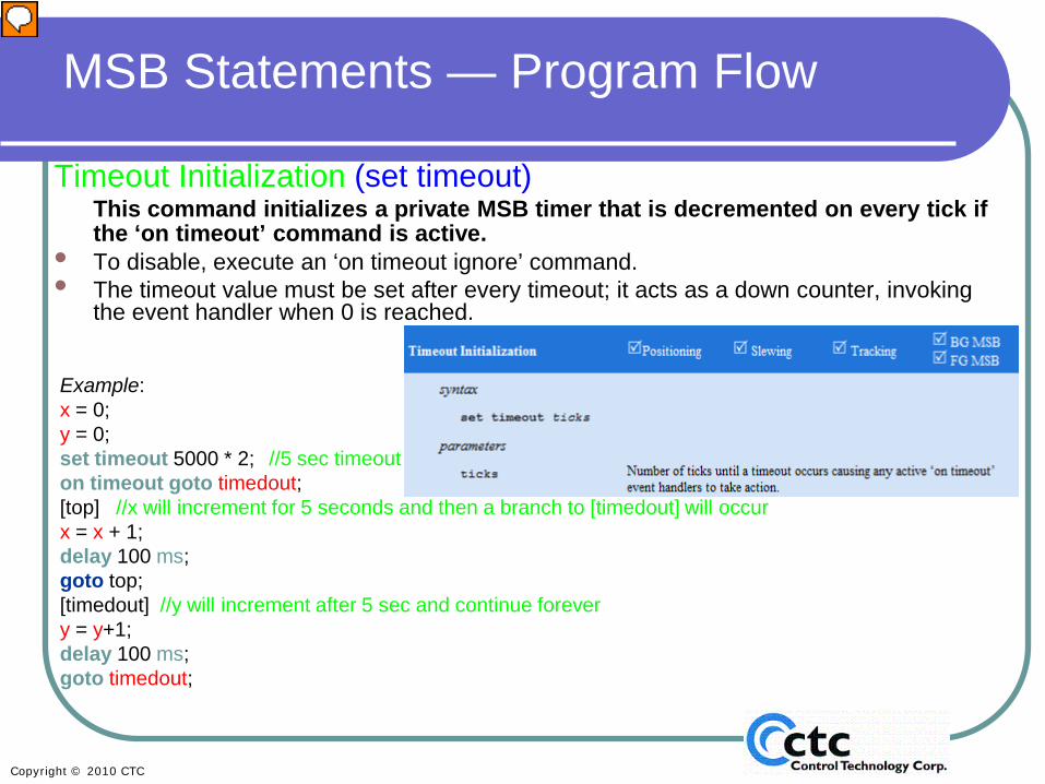
Timeout Initialization (set timeout)This command initializes a private MSB timer that is decremented on every tick if the ‘on timeout’ command is active.
• To disable, execute an ‘on timeout ignore’ command. • The timeout value must be set after every timeout; it acts as a down counter, invoking
the event handler when 0 is reached.
Example: x = 0;y = 0;set timeout 5000 * 2; //5 sec timeouton timeout goto timedout;[top] //x will increment for 5 seconds and then a branch to [timedout] will occurx = x + 1;delay 100 ms;goto top;[timedout] //y will increment after 5 sec and continue forevery = y+1;delay 100 ms;goto timedout;
Presenter
Presentation Notes
The Timeout command is used in conjunction with the Asynchronous Event Handler . This allows you to set a timeout period that will cause a branch (“goto”) or start another MSB. In this example, we are setting the timeout to 5 seconds. Note that the timeout is in 500 microsecond ticks. Using 5000 x 2 is a reminder that the program uses the 500 microsecond ticks. The set timeout command specifies the amount of time that will elapse before the jump or “start MSB” occurs. The command “on timeout” initiates the timer. The variable “timedout” is a label and is a branch within the MSB. In this example, x will increment once every millisecond after 5 seconds. After 5 seconds, that loop will stop. If the timedout event has occurred, it will jump to the timed out label at which point we will start to increment y. Note: While this is not a practical example, it is one you can physically see if you run it. Typically this command is used to check for errors and make sure that a move or other operation is complete. For example, you could set a timeout and then start a move. If the move is not complete after a given amount of time, you jump to a label that sets an alert and stops the servo, because something is wrong. This slide ends Section 5: Program Flow.
We will now cover simple motion statements including both absolute and incremental moves.
•Absolute and incremental moves will appear very similar.•Absolute moves will “move to” a specific position. •Incremental moves will “move for” a specific distance.
•All of the move commands can use either literals (numeric values) or variable to define the motion distances, speeds, and accelerations.
•S-Curve support is optionally available for the move commands, from a stopped position.
•jerk_a_req and jerk_d_req are typically set to 1 when S-curve accerlations are needed
Presenter
Presentation Notes
Section 6: Simple Motion This slide begins the section in which we introduce simple motion statements. The commands in the Simple Motion Section include both absolute and incremental motion commands. Absolute moves are moves that occur in reference to a known zero point, whereas incremental moves are moves that are based on the starting position, wherever that may be. Note that rates and distances can be specified using either literals or variables. If you want to make your moves programmable, the use of variables is necessary. By default, linear acceleration and deceleration is used. If you need S-curve acceleration and deceleration you will typically set jerk_a_req and jerk_d_req to 1. See the help menu if you need more specialized s-curve motion.
MSB Statements — Simple MotionMove Absolute, Triangular (move to)This statement generates a triangular move to the specified end position.• If the parameters acc and dec are omitted, then the default rates are used.• Linear acceleration and deceleration is used (as programmed in the axis acc and
dec properties) unless the property jerk is set to a non-zero value in which case an S-curve type profile is generated.
• The specified position may also be specified as ZPULSE_POS or ZPULSE_NEGmeaning the next encoder Z-pulse in the positive or negative directions, respectively.
Example1: move to Drillpos; /*move to the absolute position specified by the variable drillpos using default acceleration and deceleration rates. */
Example2: move to ZPULSE_POS; /*move in the positive direction until the Z pulse is seen using default acceleration and deceleration rates. */
Presenter
Presentation Notes
This move creates an absolute triangular move. The move will be in acceleration for half of the move and deceleration for the second half of the move. You have the option to specify parameters for acceleration and deceleration using “acc” and “dec” if you wish to override the default acceleration and deceleration settings. If you don’t use these, the defaults will be used. (Note that you set those defaults when setting up your axis properties.) In Example 1, we are doing a move to the absolute position defined by the variable Drillpos, using the default acceleration and deceleration rates. The second example initiates a move in the positive direction to the next known indexed pulse. Most absolute moves will allow you to set up a position as ZPULSE_POS or ZPULSE_NEG.
MSB Statements — Simple MotionMove Absolute, Speed-limited (move at n to n)Generates a trapezoidal move to the specified end position.• If it is not possible to reach the specified maximum velocity maxvelocity, then a
triangular move is generated. • If the parameters acc and dec are omitted, then the default rates are used.• Linear acceleration and deceleration is used (as programmed in the axis acc and dec
properties) unless the property jerk is set to a non-zero value in which case an S-curve type profile is generated.
• The specified position may also be specified as ZPULSE_POS or ZPULSE_NEGmeaning the next encoder Z-pulse in the positive or negative directions, respectively.
Example: move at Rapidrate to Drillpos; /*move to the absolute position specified by the variable drillpos using default acceleration and deceleration rates and the rapidrate variable for a max velocity. */
Presenter
Presentation Notes
This statement generates a trapezoidal move to a specified absolute position. If it is not possible to reach the specified maximum velocity because the move is too short for the speed and acceleration settings, a triangular move will be generated. If you don’t specify acceleration and deceleration parameters, the defaults will be used. As with most other absolute commands, you can command the position to be the next zpulse in the positive or negative position. In this example, we are setting up a move at a maximum velocity, specified by the variable called Rapidrate, to the absolute position specified by the variable Drillpos.
MSB Statements — Simple MotionMove Absolute, Trapezoidal (move trap to n using n)This statement generates a ⅓-⅓-⅓ trapezoidal move (⅓ of the time accelerating,
⅓ constant velocity, ⅓ decelerating) to the specified end position.• The acceleration and deceleration rate must be specified.• Linear acceleration and deceleration is used (as programmed in the axis acc and
dec properties) unless the property jerk is set to a non-zero value in which case an S-curve type profile is generated.
• The specified position may also be specified as ZPULSE_POS or ZPULSE_NEGmeaning the next encoder Z-pulse in the positive or negative directions, respectively.
Example: move trap to Drillpos using Rapidacc; /*move to the absolute positionspecified by the variable drillpos usingthe variable rapidacc to set accelerationand deceleration rates. The velocity used will be based on the calculationto achieve a trap move*/
Presenter
Presentation Notes
“move trap to n using n” is another trapezoidal move that uses the 1/3-1/3-1/3 formula. This means that the move will spend 1/3 of its time accelerating, 1/3 at speed, and 1/3 decelerating. You must specify the acceleration and deceleration rates. The default will not be used if you neglect to enter acceleration for this command; the program simply won’t compile. In this example, we are setting up a 1/3-1/3-1/3 trapezoidal move to the absolute position DrillPos using the acceleration rate based on the variable Rapidaccel. Caution: The velocity used in this command will be based on a calculation in order to achieve a trapezoidal move. Be careful when choosing your acceleration rates, so as not to over speed your motor, which will cause a fault.
Move Absolute, Time-limited (move in n to n)This statement generates a ⅓-⅓-⅓ trapezoidal move to the specified end
position in the specified time.• Linear acceleration and deceleration are used (as programmed in the axis acc and
dec properties) unless the property jerk is set to a non-zero value, in which case an S-curve-type profile is generated.
• The specified position may also be specified as ZPULSE_POS or ZPULSE_NEG meaning the next encoder Z-pulse in the positive or negative directions, respectively.
Example: move in Movetime to Drillpos; /*move to the absolute position specified by the variable drillpos setting the calculated velocity, accel and decel rates to make a trapezoidal move in the time specified by the variable movetime. */
Presenter
Presentation Notes
The “move in n to n” command causes a time-limited absolute move. The command generates a 1/3-1/3-1/3 trapezoidal move to a specified absolute position in a given amount of time. This command does not require you to set an acceleration or deceleration rate. The example simply tells the motor to move in the amount of time specified by the variable Movetime to the absolute position specified by the variable Drillpos using a 1/3-1/3-1/3 trapezoidal move profile. The same warning given in the previous slide about exceeding maximum speed on the motor applies here. Be aware when using this command that you could exceed your motor’s maximum speed, which will cause a fault.
Move Incremental, Triangular (move for n)This statement generates a triangular move for a specified displacement.
• If the parameters acc and dec are omitted, then the default rates are used.• Linear acceleration and deceleration are used (as programmed in the axis
acc and dec properties) unless the property jerk is set to a non-zero value in which case an S-curve type profile is generated.
Example: move for Spanmove; /*move an incremental distance specified by the variable spanmove using default acceleration and deceleration rates. */
Presenter
Presentation Notes
Now we will begin discussing incremental moves. With an incremental move, instead of moving to a specific position in reference to zero, we are telling the motor to move for a given displacement from the motor’s current position. This can be a positive or negative displacement. As you will see, the incremental move types mirror the absolute move types. The only difference is that we are moving for a specified distance instead of to a specified position. This slide covers the triangular incremental move. Using this command, a move is made for a specific distance with a triangular profile (half of the move is in acceleration and the other half of the move is in deceleration) . Also, just like absolute moves, most incremental moves allow you to specify an “override” acceleration and deceleration rate. Defaults are used when not specified. In the example, we are making a triangular move for a distance specified by the variable Spanmove.
MSB Statements — Simple MotionMove Incremental, Speed-limited (move at n for n)
This statement generates a trapezoidal move for a specified displacement.• If it is not possible to reach the specified maximum velocity maxvelocity, a triangular
move is generated.• If the parameters acc and dec are omitted, the default rates are used.• Linear acceleration and deceleration is used (as programmed in the axis acc and
dec properties) unless the property jerk is set to a non-zero value, in which case an S-curve-type profile is generated.
Example: move at Slowspeed for Spanmove; /*move an incremental distance specified by the variable spanmoveusing default acceleration and deceleration rates and using the variable slowspeed as a max velocity. */
Presenter
Presentation Notes
This is the incremental speed-limited move that generates a trapezoidal move. If a trapezoidal move is not possible, the move will have a triangular profile. In this example, we are moving at the maximum velocity specified by the variable SlowSpeed for an incremental distance specified by the variable Spanmove.
MSB Statements — Simple MotionMove Incremental, Trapezoidal (move trap for n using n)
This statement generates a ⅓-⅓-⅓ trapezoidal move (⅓ of the time accelerating, ⅓ constant velocity, ⅓ decelerating) for a specified displacement.
• The acceleration and deceleration rate must be specified.• Linear acceleration and deceleration are used (as programmed in the axis
acc and dec properties) unless the property jerk is set to a non-zero value in which case an S-curve type profile is generated.
Example: move trap for Offset using Rapidacc; /*move the incremental distance specified by the variable offset using the variable rapidacc to set acceleration and deceleration rates. The velocity used will be based on the calculation to achieve a trap move*/
Presenter
Presentation Notes
Like its absolute move partner, the “move trap for n using n” statement creates a 1/3-1/3-1/3 trapezoidal move, but for an incremental distance rather than an absolute position (see slide 82). In the example, we are telling the motor to move in a trapezoidal profile for the distance specified in the variable Offset using the variable Rapidacc to set the acceleration and deceleration rates. Unlike most motion commands, this one requires an acceleration/deceleration rate and will not use the default.
This statement generates a ⅓-⅓-⅓ trapezoidal move for a specified displacement in the specified time.
• Linear acceleration and deceleration are used (as programmed in the axis acc and dec properties) unless the property jerk is set to a non-zero value in which case an S-curve type profile is generated.
Example: move in Movetime for Offset; /*move the incremental distance specified by the variable offset setting the calculated velocity, accel and decel rates to make a trapezoidal move in the time specified by the variable movetime. */
Presenter
Presentation Notes
Similar to the absolute time-limited command, the incremental time-limited statement generates a 1/3-1/3-1/3 trapezoidal profile, but for a specified displacement rather than to an absolute position. In this example, we are moving in the time specified by the variable Movetime for the distance specified by the variable Offset. Velocities and accelerations are determined by how quickly you need to make the move, so defaults are ignored with this command.
Timebase is actually a predefined variable for any given axis and not a command statement.
• Used to override the natural time base of the target generator. When set to 1.0 (the default value), the target generator’s “time” is un-scaled.
• When set to a value between 0.0 and 1.0, the target generator’s “time” is slowed-down, effectively generating lower velocities. When set to 0.0 motion stops (allowing you to pause motion).
• Changing the timebase only effects commanded motions, it does not alter other commands such as delay.
Example: move in 2.0 for Offset; //move an incremental distance [loop]if din1 then timebase = .5; // if input1 is on run at half speed/accel/decelif din2 then timebase = 1.0; // if input 2 is on run at full speed/accel/decelgoto loop;
Presenter
Presentation Notes
Although “timebase” is a pre-defined variable and not truly a command statement, it is used very much like a command statement. Therefore it will be covered here and mentioned again in Section 7, when we discuss pre-defined variables. The variable “timebase” is used to override the natural time base of the target generator. When the timebase is set to 1 (the default), the system will run as expected and at normal speeds and accelerations. If you set it to anywhere between 0 and 1 the generator’s speed is slowed down, causing your velocities, accelerations, and decelerations to slow down . For example if you set timebase to .5, acceleration and deceleration run at half speed. If you set timebase to 0, it effectively stops motion, which is a way for you to pause motion as necessary. This will cause an instantaneous change in speed so use caution. The timebase command affects motion commands only and does not alter other commands, such as delays. In this example we are setting up an incremental move. If the system sees that digital input 1 for that axis is on, we run at half the speed. In other words, the move will take twice as long. If digital input 2 is on, the speed will be the normal or default speed. Because we are looping through the if statements to check the inputs, any change in the digital inputs from 1 to 2 will vary the speed. So, for example, a footpedal could be used during the move to speed up or slow down the motion.
MSB Statements — Simple MotionSet New End Position (new endposition relative n using n)
This statement modifies the end position for the active move command. If there is no active move, this statement is effectively ignored.
• The first form of this statement changes the end position to a new absolute position.• The second form of this statement changes the end position relative to the current position.• Using a displacement of 0 effectively stops motion here without generating a fault (unlike the stop
command).• A rate must be specified. Rate is used as the acceleration/deceleration rate for the modified profile.• DSP Linear acceleration and deceleration are used (as programmed in the axis acc and dec
properties) unless the property jerk is set to a non-zero value in which case an S-curve type profile is generated.
• ZPULSE_POS or ZPULSE_NEG should not be used with this motion command.
Example:move at 5 to 25; // start moving to 25 mmwait for rise of 1; //when din1 is activated during the move, new endposition relative 3 using 10; /*change the end position of the move to 3
from when the input seen */
Presenter
Presentation Notes
The “set new end position” statement modifies the end position of a move that is already active. If you use this command when there is no move, the statement will be ignored. There are two options available when using this command: absolute and relative. The first form of the statement changes the position to a new absolute position. The second form allows you to change the position to a position relative to the position when the command is issued. This example shows the relative option. Here we are setting up a move to move at the rate of 5 user units to the absolute position of 25. We wait for input 1 to turn on, at which point we move in the positive direction 3 millimeters, using the deceleration rate of 10. This is a simple way to set up a registration input. Note: We have capture commands available for more accurate registration. Capture commands will be covered in the advanced motion training module.
Wait for In Position (wait for in position)This statement temporarily stops the execution of the active MSB until the target generator has reached its final value and the position error, perr is within the programmed in-position window.
Example: move at Slowspeed for Spanmove; /*move speed-limitedwait for in position; //wait till motor is within the programmed in-position windowpulse 1 for 1000; //Turn on output 1 for 1 second
Presenter
Presentation Notes
The “wait for in position” command simply stops the execution of the MSB until the last commanded move is complete (when the position error is within the programmed in position window). The “in position” window is defined when you set up your axis parameters. In this example, we are moving at a rate of Slowspeed for a distance of Spanmove, waiting for that move to be complete, and then pulsing an output for one second. Since it’s important that you don’t command another move while a move is in progress, this command can be used to prevent that from happening.
Slew Begin (slew begin)This statement changes the operating mode of the axis to slewing (velocity mode).
Example: move at Slowspeed for Spanmove; /*move speed-limitedwait for in position; //wait till motor is within the programmed in-position windowslew begin; //change from position mode to slew mode
Presenter
Presentation Notes
The ”slew begin” statement is used to change your operating mode from positioning to slewing, also known as velocity mode. All other positioning moves must be completed before this command can be issued. This command changes the axis from positionng mode to slew mode. In this example, we are making a positioning move and waiting for it to be complete before switching to slew mode.
Slew At (slew at n in n)This statement alters the current slew velocity. The velocity is changed smoothly over the specified time. For an immediate speed change, specify 0.0 for time.
Example: slew begin; //change from position mode to slew modeslew at Feedrate in 0.5; //change from current speed to feedrate in 0.5 seconds
Presenter
Presentation Notes
“slew at” allows you to set or change the current slew velocity. The velocity is changed over the time specified in the command. If you need an immediate speed change, specify zero for the time. In the example, we are setting the action to slew mode and then setting the slew speed to ramp up to the velocity specified in the variable Feedrate in 0.5 seconds.
Slew For (slew for)This statement alters the current slew velocity over time (to a slew velocity of 0.0) such that some displacement is consumed.
• If the current slew velocity is 0.0, this statement is ignored.• The displacement should be unsigned, as the sign of the current slew
velocity is used to sign the displacement.
Example: slew begin; //change from position mode to slew modeslew at Feedrate in 2; //change from current speed to feedrate in 2 secondswait for rise of 3; //delay execution of MSB until input3 transitions from off to onslew for Registrationoffset; /*slew to a stop in the distance specified by the variable
registrationoffset */
Presenter
Presentation Notes
The command “slew for” basically changes the current slew velocity to zero over time until a given displacement is made. This causes the motor to come to a velocity of zero over a given incremental distance. If the slew velocity is already zero, this command is ignored. The displacement should always be a positive value. If your current slew velocity is negative, your displacement will continue in the negative direction. In other words you won’t change direction. In the example, we set the axis to slew mode; we come up to our slew rate in 2 seconds; we wait for input 3 to turn on; and then we come to a stop in the distance specified by the variable Registrationoffset.
The Homing Lab introduces the concept of a “Master” MSB to control other MSBs. The choice to use a “Master” MSB vs. starting MSBs from QS4 is a personal one. You may find that using a combination of a “Master” MSB to start some MSBs and starting a few MSBs from QS4 may work best for you.
This Lab also introduces the use of the On-board inputs and slewing to accomplish a few homing methods.
See Motion Lab 3 in the Motion Lab Manual.
Presenter
Presentation Notes
This is a good stopping point to pause for some hands-on experience. Refer to the lab manual and go to the Homing Lab. If you have equipment you can use, please be aware that you will need to tune your system ahead of time. Do not use the program in this lab without finishing your tuning! If you don’t have equipment to do the lab, you will still find it valuable to read through the lab manual. This ends Section 6: Simple Motion.
In addition to user-defined variables, there are a number of pre-defined variables for an axis in the QuickMotion language. Many of these variables correspond to properties in the QS4 world.
No more keeping track of cryptic register settings!
Presenter
Presentation Notes
Section 7: Basic Pre-defined Variables. In section 7, we’ll begin the discussion of pre-defined variables. We’ll start here with the basic pre-defined variables. Some pre-defined variables have already been covered in other areas of this training module. There are many predefined variables for each axis. Some are read-only status variables; others can be changed at runtime. The next slide begins our look at status variables.
inposHolds the state of in position.In Position is true when the target generator is inactive and when the position error (perr) is within bounds set by inposw.
overposSet to true when feedback position (fpos) exceeds poslim. Software limit.
overnegSet to true when feedback position (fpos) exceeds neglim. Software limit.
overtrqSet to true when the statemented torque trqc has been clamped to the torque limit (tlim).
rmstrqThe RMS of the statemented torque (Nm).
timeA settable, accurate (within 500usec) time counter (sec).
Presenter
Presentation Notes
Seven pre-defined status variables are listed on this slide. With the exception of “time,” last on this list, these pre-defined variables are all read-only variables. “enabled” holds the state of drive enable. This variable will read 1 when it’s enabled and 0 when it’s disabled. “inpos” tells you the state of inposition. inpos will read 1 when the position error is within the bounds set by the control variable inposw, a control variable, (which subject will be covered next). “overpos” tells you when you have exceeded the software limit set by poslim. Similary “overneg” will read 1 when the position feedback position exceeds your neglim setting. “overtrq” reads true (1) when the torque output has been clamped to the torque limit set by tlim. “rmstrq” tells you what the rms torque is, based on your tmax setting. “time” is the only status variable you can write to. This is a settable time counter accurate to within 500 microseconds. This time value always counts up. You can set it to zero at any time, and it will start counting up from there. This is useful for error checking, to test and debug your system, and see how long certain actions are taking.
Control mode – Determines the command signal the controller sends out. Set to [Torque], Velocity or Stepper.This is set using the property inspector (and thus cannot be changed in QM code) for the axis to one of the following values:
• Torque – Control loop outputs a torque statement (velocity loop is active).• Velocity – Control loop outputs a velocity statement to the drive (velocity loop is inactive).• Stepper - Control loop outputs step and direction pulses to the drive (velocity loop is inactive).
tmaxScale factor – maximum torque (Nm) that is generation at the motor when the control loop statements 10V to the drive.
• This is set using the property inspector and cannot be changed in QM code. • This property is valid when cmode is Torque.
vmaxScale factor – velocity generated when then control loop statements 10V to the drive. Scaled in RPM (rotational) or linear-units/min (linear).
• This is set using the property inspector and cannot be changed in QM code.• This property is valid when cmode is Velocity.
QuickMotion Pre-defined Variables
Presenter
Presentation Notes
The three control variables listed here are set up in the axis property window before startup. These variables cannot be changed at runtime. Cmode determines the command signal that the controller sends out. There are three options: Torque mode controls the output as a torque statement to a torque drive. In this mode the velocity loop is active. When set to Velocity mode, the control loop outputs a velocity command to the drive. In this case the velocity loop is deactivated, and the velocity drive you are connecting to closes that loop. Stepper mode causes the step & direction outputs to be used for the control loop. This is used when you’re connecting a stepper drive. In stepper mode, both the closed position loop and velocity loop are inactive. Tmax is a scale factor used only when the cmode is set to torque. This sets the maximum torque, typically in Newton meters (Nm). It scales your 10 volts to a value in Newton meters. Vmax mode is valid only when your cmode is set to velocity . This sets the maximum velocity (your 10 volts again) scaled in RPMs or in linear units per minute.
accDefault acceleration rate for absolute and incremental motionScaled in user-units/sec/sec
decDefault deceleration rate for absolute and incremental motionScaled in user-units/sec/sec.
QuickMotion Pre-defined Variables
Presenter
Presentation Notes
In contrast to cmode, tmax, and vmax, the three control variables, tlim, acc, and dec can all be dynamically changed at run time. “tlim” is the torque limit. This allows you to limit the torque to a percentage of your tmax, which, as you just learned on the last slide, is a fixed control variable you defined during parameter setup that can’t be changed at runtime. If you set tmax to 10 and set tlim is 5, you will limit your torque to 50% of maximum (5 Newton meters). “acc” is the default acceleration rate used for absolute and incremental motion. It is scaled in user units per second2. This is the acceleration default when the override option is not used in the simple motion commands. Similarly, “dec” is the default deceleration rate used for absolute and incremental motion. It is also scaled in user units per second2. This is the default deceleration rate when the override option is not used in the simple motion commands.
jerk_a_reqrequested acceleration jerk in units/sec3, read/write. Set to 1 for automatic calculation.
jerk_d_reqrequested deceleration jerk in units/sec3, read/write. Set to 1 for automatic calculation.
jerk_aacceleration actual jerk, read only
jerk_ddeceleration actual jerk, read only
QuickMotion Pre-defined Variables
Presenter
Presentation Notes
This slide discusses “jerk”. The first two variables are control variables and dynamically changeable, while the last two are actually the status variables associated with the first two. “jerk_a_req” allows you to set up an S curve acceleration. Setting it to one allows for automatic calculation. The minimum jerk that can be used is calculated by the formula (amax * amax)/vmax). “jerk_d_req” allows you to set up an S curve deceleration. Setting it to one allows for automatic calculation. The minimum jerk that can be used is calculated by the formula (amax * amax)/vmax). “jerk_a” gives you the actual current acceleration jerk values and is read only. “jerk_d” gives you the actual current deceleration jerk values and is also read only.
timebaseUsed to override the natural time base of the target generator.When set to 1.0 (the default value), the target generator’s “time” is un-scaled. When set to a value between 0.0 and 1.0, the target generator’s “time” is slowed-down, effectively generating lower velocities.
gtimebaseA global timebase variable that affects both axes. This variable in conjunction with the per-axis timebase sets the effective per-axis natural time base of the target generator.This parameter should only be set through a reference to the first axis on each card in an MSB or from a QS4 program.
QuickMotion Pre-defined Variables
Presenter
Presentation Notes
Continuing with dynamically changeable control variables, we move to “timebase”, which we covered earlier on the slide 88 in the Simple Motion section. But let’s review and expand upon it here. Timebase allows you to scale the target generator and essentially slow down your accelerations and velocities. “gtimebase” works much like timebase, except that it affects both axes, and is always used in conjunction with timebase. For example, if you set your timebase for axis 1 to .5 and your gtimebase to .5, axis 1 will run at .25 and axis 2 will ruin at .5. “gtimebase multiplies whatever rate you had set using timebase for each axis. Note that gtimebase can only be set by an MSB running on the first axis of each card or from the Quickstep4 program.
Velocity-loop factor (0.0-1.0).• When set to 1.0, the velocity loop is a classic PID structure.• When set to 0.0, the velocity loop is a classic PDF structure.• When set to a value in between, the velocity loop is a combination of both.
kvVelocity-loop proportional gain (P).• Scaled as Nm/RPM or Nm/(in r/s or linear-units/sec).
ki - Velocity-loop integral gain (I).• Scaled as Nm/RPM/sec or Nm/(in r/s or linear-units/sec)/sec.
kd - Velocity-loop derivative gain (D).• Scaled as Nm-sec/RPM or Nm-sec/(in r/s or linear-units/sec).
QuickMotion Pre-defined Variables
Presenter
Presentation Notes
Now let’s talk about tuning variables. If you have specific questions about tuning a motor, or if you’re not familiar with motor tuning parameters, please refer to the help screens. The majority of the tuning variables will typically be set using the tuning module, which was covered in Motion Lab 1. The main tuning settings (for example, bandwidth and dampening ) can be tuned using the sliding bars in the tuning module. However, if you find that you’re not getting the performance you need, you can manually tune your motor using these variables to adjust specific parameters. In other words, if your application requires fine tuning, you can accomplish that by manually setting the following variables. “kvf” refers to velocity-loop factor. This allows you to set how much of the velocity loop uses the classic PID (proportional, integral, and derivative) model and how much it uses the classic PDF (proportional, derivative, and feed-forward). Setting this to 1 gives you a pure PID structure. Setting it to zero, gives you a pure PDF structure. Anything in the middle will give you a weighted combination of both. For example .8 would be 80% PID. Typically a 70-80% PID will fit 80% of the applications encountered in the market. This parameter is controlled by the PDF/PID sliding bar in the tuning module. kv controls the velocity-loop proportional gain. ki sets the velocity-loop integral gain. kd sets the velocity-loop derivative gain.
affVelocity-loop acceleration feed-forward gain.• Scaled as Nm/RPM/sec or Nm/(in r/s or linear-units/sec)/sec
vffVelocity-loop velocity feed-forward gain.• Scaled as Nm/RPM or Nm/(in r/s or linear-units/sec)
ppgPosition-loop proportional gain• Scaled as 1000/min
pffPosition-loop velocity feed-forward gain (0.0 – 1.0)
pdeadPosition-loop dead-band (user-units)
QuickMotion Pre-defined Variables
Presenter
Presentation Notes
Additional tuning variables include the following: “aff” sets the velocity-loop acceleration feed-forward gain “vff” sets the velocity-loop feed-forward gain “ppg” sets the position-loop proportional gain. This is the main gain and is the top box you enter in the tuning module. It is not controlled by any of the slide bars. “pff” sets the position-loop velocity feed-forward gain. This is also a manual entry and is not available as a slide bar setting in the tuning module. “pdead” is the position-loop dead band. This must be set in the properties window or within an MSB and is NOT set anywhere in the tuning module. This sets the amount of following error that is allowed without the controller trying to make corrections for position error. The default is automatically set to 0. This is not to be confused with “inposw”. inposw defines when the motor is considered close enough to be in position. While the motor may be considered in position, the motion accelerator chip (or MAC) will continue to try to collapse the following error to whatever value the deadband is set to.
Feedback encoder counts per revolution (or per linear unit for linear feedback devices).sppr
Steps/rev to output when in stepper mode (cmode=stepper)mppr
Master encoder counts per revolution (or per linear unit for linear feedback devices).uun
User-units conversion factor (numerator).• Motion statements are multiplied by this value (then divided by uud) to scale user-units to
revolutions (or linear unit or linear feedback devices). uud
User-units conversion factor (denominator).• Motion statements are divided by this value (after multiplying by uun) to scale user-units to
revolutions (or linear unit or linear feedback devices).tpos
The target position scaled in user-units
tposcThe target position scaled in encoder counts
QuickMotion Pre-defined Variables
Presenter
Presentation Notes
Feedback variables include the following: “ppr” sets how many feedback encoder counts are considered in one revolution of a motor or per linear unit if you’re using a linear feedback device. “sppr” sets the number of steps per revolution you need to output when you have your cmode set to stepper. “mppr” sets the number of master encoder counts to be considered one revolution of the master or per linear unit if you’re using a linear feedback device. “uun” allows you to set user units to inches or millimeters or whatever unit you require. Your motion statements will be multiplied by this value and then divided by uud to scale user units to revolutions. So basically the formula is user units = (actual counts/ppr) * (uun/uud) This converts the encoder counts to user units. Again, user units = (actual counts/ppr) * (uun/uud). “tpos” sets the target position, scaled in user units. This will give the position that the target generator creates or the ideal position of the motor for the motion profile that you have defined. “tposc” is the same as “tpos” but is scaled in encoder counts instead of user units.
fposcThe feedback position scaled in encoder counts.
sfposcA secondary feedback position (scaled in counts).• A separately maintained feedback position similar to fposc with the exception that the
position will “wrap” (modulo) at 0 and at sfmod (unless sfmod is set to 0).
sfmodThe secondary position modulus.• Used to control when sfposc wraps around to 0.
perrThe position error (scaled in user-units).
QuickMotion Pre-defined Variables
Presenter
Presentation Notes
Here are some additional feedback variables: “fpos” is the actual feedback from the encoder, scaled in user units. “fposc” is the same as above (the actual feedback from the encoder), scaled in encoder counts. “sfposc” is the secondary feedback position. This allows you to monitor the feedback in encoder counts with a modulo, and lets you cycle the encoder counts at a given value (wrapping). It automatically resets at the value you specify in “sfmod”. No wrapping will occur if “sfmod” is set to zero. As stated, sfmod is the value you set when you want the secondary feedback position to wrap around to zero. “perr” refers to position error. This gives you the position error, which is the target position minus actual position (tpos-fpos). This value is scaled in user units.
vcmdstatemented velocity (in r/s or linear-units/sec).
velFeedback velocity (in r/s or linear-units/sec).
verrVelocity error (in r/s or linear-units/sec).
inposwIn Position window - Controls when the axis is deemed in position. Scaled in user-units.
poslimPositive over-travel limit, scaled in user-units.
neglimNegative over-travel limit, scaled in user-units
QuickMotion Pre-defined Variables
Presenter
Presentation Notes
More feedback variables: “trqc” is used when cmode is in torque mode. This variable gives you the commanded torque value. This represents in NewtonMeters what your analog output is sending to the motor, based on your tmax value. When cmode is set to velocity, “vcmd” gives you the commanded velocity. The variable “vel” is the feedback velocity based on the encoder feedback. This is based on your ppr setting, scaled in revs/sec. When cmode is set to velocity, “verr” will reflect the difference between vcmd and vel (vcmd-vel) In this case, instead of position error you’re getting velocity error – comparing the commanded velocity to the actual velocity. “inposw” defines when the axis is considered in position. It is scaled in user units and determines when a “wait for in position” command will allow the MSB to continue after a move has been made. “poslim” sets the software over-travel limit in the positive direction, and is scaled in user units. “neglim” sets the software over-travel limit in the negative direction, and is also scaled in user units.
Holds the last target position before it was modified by a “zerofeedback position” or “zero following error” statement
zfposHolds the last feedback position before it was modified by a“zero feedback position” or “zero following error” statement
invertfeedWhether to invert the way the feedback encoder counts:
0 = count normally1 = count inverted
invertmasterWhether to invert the way the master encoder counts:
0 = count normally1 = count inverted
QuickMotion Pre-defined Variables
Presenter
Presentation Notes
The variable “ztpos” holds the last target position, before it was modified by a zero feedback position or zero following error statement. This is useful, for example, in nut-driving applications, where you need to go back to the last position before you zero any following error. Similarly “zfpos” holds the last feedback position, before it was modified by a zero feedback position or zero following error statement. This is also useful in nut-driving applications. “invertfeed” allows you to invert the encoder feedback counts without having to change your wiring. So if you were to find that your encoder feedback is feeding back in the incorrect direction, this is a simple way to correct that. Similarly “invertmaster” allows you to invert the direction of counts that the master encoder is feeding in, and is also useful to make a correction without changing your wiring.
din1 – din5The state of digital inputs 1 through 5
dout1 – dout5The state of digital outputs 1 through 5
dinsThe state of digital inputs 1 through 5 as a single integer
doutsThe state of digital outputs 1 through 5 as a single integer
QuickMotion Pre-defined Variables
Presenter
Presentation Notes
Axis I/O variables are listed on this slide: “din1” – “din5” give you the independent digital state of inputs 1 – 5 to allow you to monitor if they are on or off. “dout1” – “dout5” represent the state of the digital outputs 1 – 5 and allow you to monitor them. “dins” will give you the state of all 5 digital inputs as a single decimal integer. For example if only input 1 is on this would read 1. If input 4 was on it would read 8. If inputs 1 and 4 were on it would read 9. These are the decimal equivalents of the binary values of digital inputs 1 – 5. “douts” will give you the state of all 5 digital outputs as a single decimal integer. For example if only output1 is on this would read 1. If output4 was on it would read 8. If outputs1 and 4 were on it would read 9. These are the decimal equivalents of the binary values of digital outputs1 – 5.
The digital input number to use for negative over-travel0 = disable negative over-travel checking
driveenableThe digital output number to use for “drive enable”
0 = use no output
runningThe digital output number to use for “an MSB active” (running)
0 = use no output
QuickMotion Pre-defined Variables
Presenter
Presentation Notes
Additional Axis I/O variables are listed on this slide: “reg1” – “reg2” gives you the state of registration inputs 1 and 2, respectively. “overposin” Set this value to the digital input number being used for that axis to be used for the positive over-travel limit. For example, setting this to 1 will assign din 1 on the axis card to the positive over-travel limit switch. Setting this to zero will disable over-travel positive checking. If your input is N.C. set the input number to a negative value instead of a positive value. “overnegin” Set this value to the digital input number being used for that axis to be used for the negative over-travel limit. For example, setting this to 1 will assign din 1 on the axis card to the negative over-travel limit switch. Setting this to zero will disable over-travel negative checking. If your input is N.C. set the input number to a negative value in stead of a positive value. “driveenable” assigns which output the axis will turn on when the driveenable command is issued in an MSB for the purpose on enabling your servo or stepper drive. “running” allows you to turn on an output when an MSB is active (or running). If set to zero there is no output. This slide ends Section 7, the final section of the QuickBuilder basic motion tutorial. Remember that the QuickBuilder application contains online help and a QuickStart guide. Technical support contact information is also available on the CTC website, www.ctc-control.com.