Embed Size (px)
Citation preview
Control systems to comply withASHRAE Standard 62-1989
Acceptable indoor air quality can be achieved by properly selecting/sizing air dampers and by using air flow sensors
By John L Levenhagen, P.E. Life Member ASHRAE
M uch has been writte. n about indoor air quality (IAQ) and the impact thal it has on the American worker in office
buildings. However, for many years, ASHRAE has recognized the need to be aware of the air quality in commercial as well as residential buildings, which are the livelihood of consulting engineers, contractors and the suppliers of equipment used in those buildings.
ASHRAE was involved in creating standards for proper ventilation many years ago. The first ASHRAE standard on the subject of proper ventilation was created by a committee back in 1973 and it was referenced in ASHRAE Standard 90-1975.
When that first standard was created, there was not much concern about the energy needed to supply buildings with comfortable environments. As an engineering community, we were more concerned about the comfort of the occupants of commercial buildings.
Then, along came the Arab oil embargo and the whole situation changed. In 1981, the standard was revised to reflect the concern for energy conservation and, as a result, some drastic changes were made in the amounts of ventilation air brought into buildings.
That standard also referenced the smoking and non-smoking areas of buildings as having different requirements for ventila
. tion air. The amount of ventilation air recommended was reduced in an effort to save energy.
When the IAQ issue reared its ugly head through the knowledge that was gained from the tight building syndrome as well as other problems in modern buildings, the
engineering community realized that something must be done with the standard.
So, in 1983, even though the standard was not due for the normal five-year review cycle, it was decided to revise it sooner. The document we have now, known as ASHRAE Standard 62-1989, will be discussed in this article. 1
ASHRAE Standard 62-1989, as well as its predecessor standards, have addressed the problems of indoor air quality with a view towards ensuring that the amount of ventilation air introduced into the building (either by natural means or by forced ventilation through the air handling units) is adequate to satisfy the biological and medical needs of the occupants.
In fact, the recent out-of-court settlement of a lawsuit in Los Angeles demonstrates that, had the building owners been able to prove that they were taking in the ventilation air that was recommended in the ASHRAE standard, the case would not have been decided against the defendants and in favor of the plaintiffs. 2
Because most ASHRAE engineers are not doctors, chemists or epidemiologists, they cannot determine the permissible level of pollutants in a building. Instead, engineers should be concerned with the quantity and quality of the ventilation air, and they should assume that the proper
About the author
John I. Levenhagen is an engineering consultant in Oceanside, California. He received a BSME from Purdue University. Levenhagen is a member of ASH RAE TC 1.4 (Control Theory and Application) and TC 6.2 (District Heating and Cooling).
amount will satisfy the requirements set forth by the scientists.
Accordingly, there will be no attempt to qualify or quantify the amounts of pollutants in the outdoor air in this article. It is also assumed that, when the outside air amounts are introduced in accordance with ASHRAE Standard 62-1989, that the quality of the air in the building will be adequate for the average occupant.
So, how does the standard affect the control companies and their efforts to comply with it? With ASHRAE's technical committee structure, engineers can be assured that all facets of our industry, including the controls manufacturers, were involved in creating the standard.
As far as the standard is concerned, there was either a member of the controls engineering community on the committee that created the standard, or there was a detailed peer review process that assured that the concerns of the controls manufacturers were addressed.
A reading of the standard will reveal a few places where its writers were concerned with the role of the controls companies and controls engineers. For example, in section 5.1 on page 5, there is a reference to providing "Flow Measurement" in the first sentence. In section 5.4, there is a definite reference to the control problems with VAV systems and the standard's effort to maintain acceptable IAQ.
Complying with Standard 62-1989 In the final analysis, the purpose of the
control systems that operate outside air, return air and exhaust air dampers is to control those dampers and introduce the correct quantity of ventilation air to meet
ASHRAE Journal September 1992
1he standard's requirements. In addition, the total stalic pressure drop across the 'al 'Jd. para,,,., I bl d d all commerc1 but mgs must be designed items near the damper (filters, ductwork, blaci . ··e a e ampers instead of opposed so char there is a slight positive static pres- etc.) is a reasonable drop rhac will allow som' ~dampers (as mentioned above) can sure in the building to prevent unwanted adequate control. con " -"rimes be justified even though the infiltration of outdoor air. So, the size of the dampers plays an dam. rol specifications call for modulating
Howe er, it shouJd be noted that, with important part in the control system's abil- will 1
""'rs. An ana lysis of the flow patterns today's eight buildings, what goes into a ity to bring in the amount of air specified bl al. ~ :h~w where opposed blade or parallel building must also get out of ii; chat is, in the standard. In other words, there must ,.._ ·• ampers are appropriate. after the required positive static pressure is be a proper pressure drop across a damper a C\:·
0.1ost concern are the false ideas that
taken into account. In other words, there for it to control properly. troi:·,~·:.~m level of ~~ntrol signal from a con-must be an analysis of the balance of the Stratification as a result of improper or ; '·or t~epos1t10n of the damper blade, supply systems and the exhaust systems. damper locations can also affect the IAQ . . 'e position of the damper motor's
Failure to do this will result in a building in cercain portions of the building. Using - ~~;~, : ~-arm ~re in.dica~ion.s ?f the percen-
~~ cith~ wo hl~ m wo~wmtk~~r::::::::::::::::~-n~f~o~u~b~~~e~a~rr~b~e~m~g~1~~~e~ct:e:d~in:t:o~th:eJ sure. The outside doors will either stand II open or they will be difficult to open.
The standard calls for a cenain percenmge of ventilation air to be introduced into t:he builrung, normally through the air-handling system. This can be done with constant volume systems through many control schemes such as sectionalized dampers for the outside air dampers or through the use of minimum position relays. Naturally, rhe controls must also involve any ocher dampers in the scheme including return air and exhaust air dampers.
One control concept chat has been used for many years is the economizer cycle. This cycle utilizes outdoor afr when the temperatures and total heat of the outdoor air are desirable to use. It is advantageous as ventilation air when it neither needs to be heated nor cooled; for example, using outdoor air with a temperature between 50°lo65°F(l0°to 18°C).
When the system is in the flushing mode taking in IOOOJo outdoor air or close to that, there is little concern for ventilation air to meet the standard's requirements. However, when the system returns to the minimum percentage of outside air, the standard and the control engineer must get involved. The key point here is not the types of cycles that are specified, but the way they are specified and installed.
Improper specification of damper types (parallel blade or opposed blade dampers) for a particular location is one example of the necessity for specifiers to understand that air through a damper is sometimes only bent and not controlled.
One typical mistake is to put the outside air damper rigbt behind the outside air louver. Tbe louver is designed for 500 fpm (2.5 mis) velocity. That is much too slow to control with a damper. At that velocity, the pressure drop across the damper will clearly be coo low to control the ventilation air.
The damper size must be based on a reasonable static pressure drop across the damper. It has been suggested that 250Jo of
ASHRAE Journal September 1992 (Circle No. so 41 1 Header Service Card)
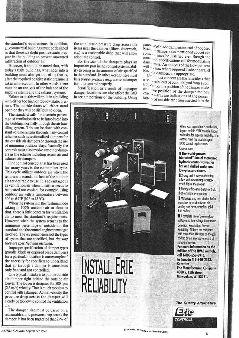
When your ceputotion is on the line depend on Erle HVAC controls. Kn~ worldwide for superior reliobiliry, Erie controls meet the most stringent HVAC control requiremenls. Oioose from: I The worfd-proven Motortrol® line of motorized hydronic control valves for hot and chilled water and low-pressure steam. 12-way ond 3-way modulating wives with new microprocessorbosed digilol lhermostot. I Energy-efficient rodiotor controls !hot eliminate overheating. I Motorized and n6n-alectric boiler operators to provide Worm oir zoning and draft con!Tol for solid fuel boilers. · "" . I A complete line of ocrurola lowvoltoge ond llne-volfoge !hermostots... Selection, Reputation. Sesvice. Reliability. All &om the company witfi more than 40 years on the job, bocksll by on impres.sjve tl)(ord of soles ond selVice. For more.information on the full line of Erie HVAC controls, 1 call 1-800-558-3916. In Canada 416-640·2363. Orwrltet
. Erie Manufacturing Company 4000 S. 13th Street · Milwaukee, WI 53221.
The Quality Altemative .
CONTROLS . ··.
41

42
ASHRAE Standard 62-1989
building. These are the biggest myths of all in the control world; they could not be further from the truth.
These three factors do not indicate the cfm flowing through the damper. The only way to accurately determine the amount of outside air coming into the building is by using flow measuring devices.
CAV versus VAV With the exception of lOOOJo outside air
units (such as in hospitals), the above concepts apply to most constant air volume (CAY) systems such as multizone units, single-zone units, dual-duct units and induction systems. The bottomline is that each and every system must be analyzed separately for the uniqueness that may apply to the dampers and their locations.
CAY systems are usually easy to control when care is taken in sizing the dampers. The locations of the units as well as the dampers are also important. Furthermore, a thorough understanding of the dynamics of the air flows around a building must be infused into the system design. This will prevent such situations as air flowing backwards through the outside air intake under certain conditions of wind and building orientation.
With VAY systems, it should be remembered that it's a different story altogether. For example, in Table l, we see that designing a CAY system taking in 20 cfm per person is easy. But, design becomes more complicated with aVAV system because it changes the total volume of air circulated.
There is no problem when the VAV system is in the economizer cycle because
; it's using 100% outside air. The problem occurs when the VAY system is in the minimum outdoor air cycle. Then, the total volume of air is reduced as the VAY boxes begin to reduce the air requirements in the spaces.
To compound this problem, VAY systems are typically specified with return air fans. This causes additional control problems, with the requirements changing to
include the control of both the supply and return fans to maintain the proper static pressure within the space.
Air control methods A few control methods used today are
popular. 3 Although a complete understanding of these methods is necessary for the proper operation of a VA V system, they are not always germane to introducing the proper amount of outside air to meet Standard 62-1989. The methods most commonly used are:
• Direct building static pressure control, • Fan capacity matching through
balancing, • Volumetric matching of fans, and • Return air duct static pressure control
(for labs, clean rooms, etc.). Each of these control methods has its
drawbacks and is preferred by different engineers for different reasons. Some are more complicated than others.
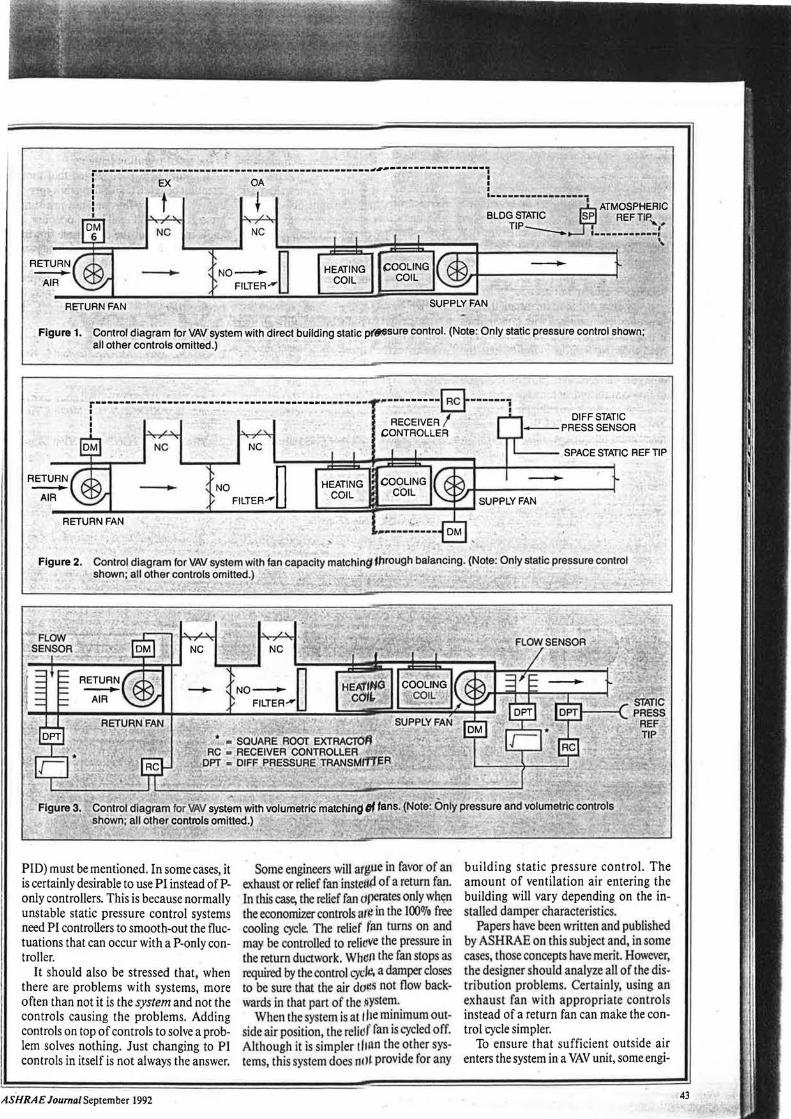
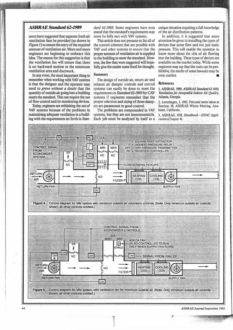
The one method preferred by this author is volumetric matching of fans. It is the only one of the four that will ensure that the desired amount of ventilation is being brought into the building. The first three control methods listed above are shown in Figures l, 2 and 3.
Figure 1 shows a system where the return air fan is controlled based on building static pressure. Here, positive building static pressure is maintained to be sure there is no infiltration caused by the build-ing's porosity. ·
This is the simplest method, but it is not always preferred because it depends on sensing a building's static pressure with the outside air as the reference static pressure. However, the outside air static pressure is not ever stable so that it can be depended on.
In Figure 2, the fans are again controlled by static pressure, but this time it is the static pressure in the ductwork. Here, the fans are adjusted so they always leadlag each other to maintain a difference in air flows (in cfm). This ensures that there is always a positive static pressure in the building. However, to make this system work, the balancing contractor must ensure that the two fans are matched properly.
In Figure 3, the fans are controlled so there is a positive static pressure in the building, but the controls also use flow sensor stations. These are much more reliable than statie pressure controls.
As indicated, the problem with VA V systems is when the VA V boxes are all in a reduced air volume mode and the 'supply fan as well as the return fans are throttled down to minimum air flow. In this case,
special arrangements with the control cycles may be needed. One example is to use a system of minimum outdoor volume control, as shown in Figure 4.
This type of control system can be utilized whenever the amount of air required for ventilation is greater than that required for building pressurization. Here, the minimum outside air damper is operated by a flow sensor. This maintains the required amount of ventilation air and overrides the economizer control, which otherwise would reduce the ventilation air below the Standard 62-1989 requirements. Figure 4 shows a system with a return fan, but there are other cycles that can be designed without the return fan system.
Another solution from a control standpoint is sizing the minimum damper or control system to introduce the ventilation air required when the fan is at its lowest volume flow condition. This solution may require additional energy for preheating the ventilation air under severe weather conditions. The energy saved with the reduction in horsepower at reduced flows may be partially offset by the needed energy to preheat the ventilation air.
However, there could be some tradeoffs in the design. It is possible to integrate the control systems mentioned and those that have been suggested into control systems that do not use a return fan and also those systems that use instead an exhaust fan.
In the final analysis, the controls of the outside air, return air and exhaust air dampers in a VA V system must be studied thoroughly. The designer must determine the entire air balance of the system including all the "what-ifs" that can occur.
Remember, when the VA V system reduces the air flow, the amount of ventilation air will also be reduced if the design is not proper. Of course, it is possible to design VA V systems where different types of VA V boxes are used to help keep the minimum air flow to a point where the ventilation air meets the standard.
A recent caveat for VA V systems involves morning warm-up control systems. In such VA V systems, people who are in the building during the warm-up cycle may complain about not receiving any ventilation air.
One solution is to reschedule the warmup cycle to an earlier time when there is no possibility of anyone working in the building. Another solution is to use ventilation air during the warm-up cycle just as in other times. However, this may require additional energy.
Also regarding controls for VA V systems, the types of controllers (P, PI or
ASH RAE Journal Septebmer 1992
NO- n FILTER...-u
HEATING COOLING COIL COIL
Figure 1. Control diagram for VAV system with direct building static pf§.Ssure control. (Note: Only static pressure control shown: all other controls omitted.)
;---:------------------------------------------ ----------~------1 • I I
RETURN FAN
RECEIVER/ CONTROLLER
DIFFSTATIC - PRESS SENSOR
...__ __ SPACE STATIC REF TIP
-Figure 2. Control diagram for VAV system with fan capacity matching Uirough balancing. (Note: 9n1y static pressure control
shown; all other controls omitted.) • . ~ ~
PID) must be mentioned. In some cases, it is certainly desirable to use PI instead of Ponly controllers. This is because normally unstable static pressure control systems need PI controllers to smooth-out the fluctuations that can occur with a P-only controller.
It should also be stressed that, when there are problems with systems, more often than not it is the system and not the controls causing the problems. Adding controls on top of controls to solve a problem solves nothing. Just changing to PI controls in itself is not always the answer.
ASH RAE Journal September 1992
NO_ n FILTER...-u
·~
Some engineers will arMue in favor of an exhaust or relief fan instell~ of a return fan. In this case, the relief fan dperates only wh~n the economizer controls are in the 100% free cooling cycle. The relid fim turns on and may be controlled to reliave the pressure in the return ductwork. Whdll the fan stops as required by the control cyck\ a damper closes to be sure that the air does not flow backwards in that part of the !iystem.
When the system is at j he minimum outside air position, the relief fan is cycled off. Although it is simpler tf1un the ocher systems, this system does n<H provide for any
building static pressure control. The amount of ventilation air entering the building will vary depending on the installed damper characteristics.
Papers have been written and published by ASHRAE on this subject and, in some cases, those concepts have merit. However, the designer should analyze all of the distribution problems. Certainly, using an exhaust fan with appropriate controls instead of a return fan can make the control cycle simpler.
To ensure that sufficient outside air enters the system in a VAV unit, some engi-
43
1 I I
I
44
ASHRAE Standanl 62-1989
neers have suggested that separate fresh air ventilation fans be provided (as shown in Figure 5) to ensure the entry of the required amount of ventilation air. More and more engineers are beginning to embrace this idea. The reason for this suggestion is that the ventilation fan will ensure that there is no backward motion to the minimum ventilation area and ductwork.
In any event, the most important thing to remember when working with VAV systems is that the designer and the operator may need to prove without a doubt that the quantity of outside air going into a building meets the standard. This can require the use of flow control and/or monitoring devices.
Today, engineers are rethinking the use of VAV systems because of the problems in maintaining adequate ventilation in a building with the requirements s~t 'forth in Stan-
dard 62-1989. Some engineers have even stated that the standard's requirements may never be fully met with VAV systems.
This article does not presume to list all of the control schemes that are possible with VAV and other systems to ensure that the proper aniount of ventilation air is supplied to the building to meet the standard. However, the few that were suggested will hopefully give the reader some food for thought.
Summary The design of outside air, return air and
exhaust air damper controls and control systems can easily be done to meet the requirements in Standard 62-1989 for CAV systems if engineers remember that the proper selection and sizing of those dampers are paramount to good control.
The problems are compounded in VAV systems, but they are not insunnountable. Each job must be analyzed by itself as a
unique situation requiring a full knowledge of the air distribution patterns.
In addition, it is suggested that more attention be given to installing the types of devices that sense flow and not just static pressure. This will enable the operator to know more about the cfm of air flowing into the building. These types of devices are available on the market today. While some engineers may say that the costs can be prohibitive, the results of some lawsuits may be even costlier. •
References I. ASHRAE. 1989. ASH RAE Standard 62-1989, Ventilatio11for Acceptable l11door Air Quality. Atlanta, Georgia. 2. Levenhagen, J. 1992. Personal notes taken at Seminar 18, ASHRAE Winter Meeting, Anaheim, California.
3. ASHRAE. 1991. Handbook-HVAC Applications.Chapter 41.
Figure 4. Control diagram for VAV system with minimum outside air volumetric controls. (Note: Only minimum outside air controls shown; all other controls omitted.)
CONTROL SIGNAL FROM ' ..--.......,.--'------ ECONOMIZER CONTROLS
O.A. MAX MIN
g MINOA FAN (ALSO CONTROLLED TO RUN ONLY WHEN SUPPLY FAN RUNS)
Figure 5. Control diagram for VAV system with ventilation fan for minimum·outside air. (Note: Only minimum outside air controls shown; all other controls omitted.)
ASHRAEJournalSeptember 1992


![SELECTED DECISIONS OF THE HUMAN RIGHTS · PDF fileHUMAN RIGHTS COMMITTEE under THE OPTIONAL PROTOCOL Volume 3 ... No. 360/1989* [36] ... 62 No. 181/1984](https://img.pdfslide.us/doc/110x75/5aa0eae17f8b9a8e178eaaa9/selected-decisions-of-the-human-rights-rights-committee-under-the-optional-protocol.jpg)


![[1003] 1) — 11-1 1989 t Pc Y a —53 y Y p —Pay 62, 72%) 35data.jci-net.or.jp/data_pdf/11/011-01-1003.pdf1)— 11-1 1989 t Pc Y a —53 y Y p —Pay 62, 72%) 35 Created Date 3/1/2004](https://img.pdfslide.us/doc/110x75/5ad4012a7f8b9a0f198e61b0/1003-1-11-1-1989-t-pc-y-a-53-y-y-p-pay-62-72-11-1-1989-t-pc.jpg)


![HIGH COURT OF AUSTRALIA - · PDF fileHIGH COURT OF AUSTRALIA CHAN v. MINISTER FOR IMMIGRATION AND ETHNIC AFFAIRS [1989] HCA 62; (1989) 169 CLR 379 F.C. 89/034 Immigration -](https://img.pdfslide.us/doc/110x75/5a9c95197f8b9a7f278b4ef2/high-court-of-australia-court-of-australia-chan-v-minister-for-immigration-and.jpg)