Embed Size (px)
Citation preview

Space Vehicle Control Systems
In This Chapter You’ll Learn to...
Describe the elements of and uses for control systems
Explain the elements of space vehicle attitude determination and control subsystems and describe various technologies currently in use (enrichment topic)
4.3.1
Outline
4.3.1-1 Control Systems
4.3.1-2 Attitude Control
Having the Right AttitudeAttitude Dynamics Disturbance TorquesSpacecraft Attitude SensorsSpacecraft Attitude
ActuatorsThe Controller

Space Mission Architecture. This chapterdeals with the Spacecraft segment of theSpace Mission Architecture.
magine you’re a one-person spacecraft, flying the mannedmaneuvering unit out of the Space Shuttle’s payload bay, as shown inFigure 4.3.1-1. Your mission is to fly to a crippled satellite and install a
new black box. You must somehow manipulate the joy sticks in yourhands to control your position, velocity, and orientation so you’re lined upwith the access panel on the spacecraft. How should you rotate? In whichdirection should you fire your thrusters? Do you speed up or slow down?Although this may sound like a fun scenario for a video game, we mustanswer these questions for nearly all spacecraft. In this chapter we’ll beginby examining the basics of any control system and then see how we canapply this process to rotate a spacecraft in space.
Figure 4.3.1-1. Space Vehicle Control. An astronaut flying the manned maneuvering unit(MMU) must carefully control rotation, position, and velocity to accomplish the mission (andnot get lost in space!). (Courtesy of NASA/Johnson Space Center)
I
4.3.1-395

Figure 4.3.1-3. A Simple Heating ControlSystem. With the simplest type of heatingcontrol system, we throw logs on the fire andwait for heat to come out, warming the room.Unfortunately, such a simple system is “open-looped,” so there is no guarantee we’ll get theright amount of the desired output.
4.3.1.1 Control Systems
In This Section You’ll Learn to...
A system is any collection of things that work together to producesomething. Systems have inputs (what goes in), outputs (what comes out),and some process in between that turns the inputs into outputs. Inelectronic systems, the inputs and outputs are called signals. The part ofthe system that performs the process is typically called the plant. The plantis usually an “equal-opportunity” processor that will respond to eitherprecisely calculated inputs or random environmental inputs or both.
To simplify our discussion of systems, we like to illustrate them usingblock diagrams, in which lines represent input and output signals andboxes represent the plant or other components. Figure 4.3.1-2 shows thesimplest type of system block diagram. For space-vehicle applications,the success or failure of the mission depends on the output of varioussubsystems. Therefore, we’re most interested in a specific class of systemscalled control systems. Control systems are everywhere. If you’ve everflushed a toilet, driven a car, or turned up the thermostat on a frigidwinter night, you’ve used a control system.
To understand how we use control systems, let’s look at a problemwe’re all familiar with—heating a house. In the old days, people heatedtheir homes only with fireplaces. They started with some desired result“It’s too cold in here, let’s warm things up!” and decided what action totake—“Throw some logs on the fire!” The logs burned, providing heat,and the house warmed up. We can draw a simple diagram for this wholeprocess, as shown in Figure 4.3.1-3. As you can see, the input (logs) gointo the fireplace and burn, which produces the output (heat).
Describe the elements of a system
Explain the difference between open-loop and closed-loop control systems and give examples of each
Describe the steps in the control process
Apply block diagrams to describe the functions of control systems
Figure 4.3.1-2. System Block Diagram. All systems take some input (or inputs), performsome process in the “plant,” to produce an output (or outputs). We illustrate the functions ofsystems using block diagrams, in which input and output signals are shown as arrows andthe plant, or other components, are shown as boxes.
4.3.1-396

Unfortunately, this simple control system has one major drawback. Ifyou put on too many logs, the room can get too hot. And, when you wentto sleep at night, there was no way to ensure the house would still bewarm in the morning. A system that can’t dynamically adjust the inputsbased on what’s actually happening is an open-loop control system. Ofcourse, people lived with this kind of heating system for thousands ofyears (and still do). But eventually we got tired of waking to a cold houseand invented the modern home-heating system. Let’s see what makes thismodern control system an improvement.
On cold winter nights, we turn up the dial on the thermostat to adesired temperature and wait for the heat. After some time, the furnacereaches its operating temperature, turns on its fan, and the room tempera-ture starts to rise. When the house reaches the desired temperature, thefurnace shuts off. Simple, right? But what’s really going on here?
As with any control system, we have some desired result—a house at20° C (75° F). This desire is what we tell the thermostat when we set thedial. For this example, the heating-control system has different jobs. First,it measures the current temperature in the house using a thermometer. Incontrol-system lingo, the thermometer is a sensor, because it measures theoutput of the system. Next, the control system decides what to do usingthe “brains” of the thermostat. The “brain” of the thermostat is called thecontroller, because it compares the sensor output to the desired output anddecides what type of input the system needs. If it’s cold outside, the“environmental inputs” will eventually reduce the temperature in thehouse to less than 20° C (75° F). When this happens, the controller knowsto turn on the furnace. Similarly, if the temperature is greater than 20° C(75° F), it knows to turn off the furnace. Finally, the furnace carries out thethermostat’s decision by providing heat. We call the furnace an actuator,because it takes commands from the controller and produces the requiredoutput for the system. Figure 4.3.1-4 illustrates the various pieces of thiscontrol system.
Figure 4.3.1-4. The Modern Home-heating System. A modern home-heating systemcontinually measures the temperature and decides when to turn the furnace on or off.
4.3.1-397

Figure 4.3.1-5. Block Diagram for aHeating-control System. It’s easier torepresent the elements of a control system
We call this type of system a feedback control system or a closed-loopcontrol system, because we have a thermometer (sensor), whichcontinually measures the current temperature and feeds this informationback to the thermostat (controller). With this information, the thermostatproduces the correct furnace (actuator) commands to maintain the houseat 20° C (75° F), despite environmental inputs (close the window please!).Again, we can draw a simple block diagram to illustrate what’s going onin this system, as shown in Figure 4.3.1-5.
In this simple example we’ve identified the four basic tasks all controlsystems must do
• Understand the system’s behavior—how the plant will react to inputs, including environmental inputs, to produce outputs. This is also known as the plant model.
• Observe the system’s current behavior—using sensors
• Decide what to do—the job of the controller
• Do it—using actuators
Closed-loop control systems, such as the heating system describedabove, are in cars, planes, spacecraft, and even the human body. They areextremely useful because, unlike open-loop systems, they can make asystem do what we want even in the face of random environmentalinputs.
On space vehicles, control systems are an integral part of virtually allpayloads and subsystems. For example, a remote-sensing payload mayneed to control
• Exposure
• Aperture settings
• Lens-cover mechanisms
• Imaging time and duration
To support the payload, each subsystem in the spacecraft bus needs tocontrol something as well
• Momentum (angular and linear)—the job of attitude and orbit control subsystem (AOCS)
• Data (bits and bytes)—the job of communication and data-handling subsystem (CDHS)
• Power (current, voltage, distribution)—controlled by the electrical power subsystem (EPS)
• Internal environment (temperature, air, water, food, waste)—the job of environmental control and life-support subsystem (ECLSS)
• Loads (bending, twisting, shaking)—handled by structures and mechanisms
• Rocket thrust (valves, pressure, temperature)—provided by the propulsion subsystem
4.3.1-398

output. Inputs and outputs are called est illustrate systems using block
tput. Unfortunately, open-loop
better ensure we get our desired sired outputs (what we want), and
s, including environmental inputs, to
stems to control
ems (AOCS)
(CDHS)
nmental control and life-support
In the rest of this chapter, we’ll focus our attention on momentumcontrol—angular and linear—the job of the attitude and orbit controlsubsystem (AOCS). This is the “steering” function we described for theschool bus in Chapter 11. As you can imagine, in operation the twofunctions of controlling angular and linear momentum often overlap. (Inpractice, it’s difficult to change just angular momentum without havingsome effect on linear momentum—try spinning a frisbee without movingit!) However, for purposes of discussion here, we’ll keep the two functions(angular and linear momentum control) separate. In Chapters 13 and 14we’ll return to the other subsystems to see their control systems in action.
Section Review
Key Concepts
All systems take some input and complete some process to produce ansignals, and the element doing the process is called the plant. We can bdiagrams.
The simplest type of control system is open-loop. Input produces an ousystems can’t dynamically adjust inputs to control outputs.
Feedback control systems, also called closed-loop control systems, canoutput because it can sense outputs (what we get), compare them to deadjust inputs as needed. Closed-loop control systems apply four steps
• Understand the system’s behavior—how the plant will react to inputproduce outputs. This is also known as the plant model.
• Observe the system’s current behavior—using sensors
• Decide what to do—the job of the controller
• Do it—using actuators
Virtually all spacecraft payloads and subsystems rely on closed-loop sy
• Imaging, communicating, and operating other missions—payloads
• Momentum (angular and linear)—attitude and orbit control subsyst
• Data (bits and bytes)—communication and data-handling subsystem
• Power (current, voltage, distribution)—electrical power subsystem
• Internal environment (temperature, air, water, food, waste)—envirosubsystem (ECLSS)
• Loads (bending, twisting, shaking)—structures and mechanisms
• Rocket thrust (valves, pressure, temperature)—propulsion subsystem
4.3.1-399

4.3.1.2 Attitude Control
In This Section You’ll Learn to...
We’ll begin our discussion of the space vehicle’s attitude and orbitcontrol subsystem (AOCS) by focusing on the attitude part of theproblem. Attitude defines a vehicle’s orientation in space. For example, ifwe want a spacecraft to take pictures of a particular spot on Earth, weneed to align the payload so it points at the spot. In this case, we’d needto control the spacecraft’s attitude so it points “down,” toward Earth. Inspace terms, we say, “down toward Earth” is the nadir direction. Theopposite direction, away from Earth toward space, is the zenith direction.
Similarly, launch vehicles need to control their attitude to steer into thecorrect orbit and keep forces aligned along the long axis where they arestrongest. However, in this section, we’ll focus mainly on the uniqueproblems for spacecraft. Because this function is so important, it issometimes given a separate name—attitude determination and controlsubsystem (ADCS). In this section, we’ll refer to it by that name.Regardless of the name given to the subsystem, its job is the same—keepits spacecraft pointed in the right direction.
In the last section, we learned that all closed-loop control systems havethe same basic components and functions, as shown in Figure 4.3.1-6. Inthis section, our “desired state” is the specific attitude a vehicle needs todo its mission. We start by defining this desired attitude. Then, we moveon to the first function of any control system—understanding systembehavior. We explore attitude dynamics to understand the basicprinciples that govern a vehicle’s angular momentum. We also see howvarious phenomena in the space environment affect a spacecraft’sattitude. After this introduction, we’ll turn our attention to attitudesensors to learn how we use instruments to “look out the window” todetermine a spacecraft’s orientation in space. Before looking at attitudecontrollers, we’ll first examine the types of attitude actuators available todesigners. With these in mind, we’ll finally consider the controller and seehow the entire subsystem fits together (Figure 4.3.1-6).
Having the Right AttitudeBefore we go too far, let’s review some basic terms used to describe
attitude. To describe attitude we must define a coordinate system andwe’re now interested in rotation rather than translation. For this reason,
Explain and apply important concepts in attitude dynamics to the problem of space vehicle control
Describe key elements and technologies used in a space vehicle’s attitude determination and control subsystems and explain them using block diagrams
4.3.1-400

Figure 4.3.1-7. Body Frame. We describeattitude in terms of rotations in degrees (orradians) around one or more of the body-centered axes from the body frame. Forairplanes and vehicles like the Space Shuttle,the -direction points out the nose, the -direction points out the left wing, and the -direction (out of the page) completes the right-hand rule. For box-shaped spacecraft without a“nose” or wings, designers pick convenient,preferred directions through the center of massto define the body frame.
X YZ
we define attitude in terms of angles instead of distances. Attitude isdescribed as an angular rotation with respect to a body-centeredcoordinate frame, called the body frame, where points out the nose, out the left wing, and out the top, as shown in Figure 4.3.1-7. It isusually given as roll, pitch, and yaw angles, where roll is a rotation aboutthe axis, pitch is a rotation about the axis, and yaw is a rotation aboutthe axis, as shown in Figure 4.3.1-8. Obviously, box-shaped spacecraftdon’t have noses or wings. Instead, designers define preferred directionsthrough the center of mass in a body-centered system and then theydefine roll, pitch, and yaw angles with respect to it.
Now that we showed how to describe a spacecraft’s attitude, how dowe determine whether it has the right attitude? We must first know whatattitude it needs. Typically, we describe attitude-control requirements interms of accuracy and rate of attitude change. To understand what wemean by attitude or pointing accuracy, let’s pretend we’re trying to pointa laser beam at a target, as shown in Figure 4.3.1-9. Our ability to keep thebeam on the target depends on the size of the target and the steadiness ofour hand. It should make sense that the smaller the target, the moresteady our hand must be to maintain the laser on it. Hopefully, even asour hand wavers, the beam will tend to stay within a cone, more or lesscentered on the target. The angular size of this cone defines pointing or
Figure 4.3.1-6. Closed-loop Control System. All closed-loop control systems have thesame basic elements. The desired state is one input to the controller. It compares this stateto the actual state from the sensors. By comparing the difference between these two inputsignals, it decides on specific commands to send to the actuators. Actuator changes, alongwith environmental inputs, affect the final output of the plant. System sensors detect andmeasure this output.
X YZ
X YZ
Figure 4.3.1-8. Describing Attitude. We describe space-vehicle attitude in terms of roll,pitch, and yaw angles around the axes of the body frame.
4.3.1-401

attitude accuracy, ψ. For a spacecraft trying to point an antenna at a groundstation on Earth, for example, the control system must be accurateenough to keep the radio beam focused over the receiver antenna.
To get a better feel for what we mean by attitude or pointing accuracy,let’s pretend the target in Figure 4.3.1-9 is about the size of a 25-cm (10-in.)dinner plate. We know the pointing accuracy, ψ, and the distance to thetarget, h. To find the apparent diameter of the target we can hit, D, we use
D = h ψ (4.3.1-1)
whereD = approximate diameter of target (m)h = distance to target (m)ψ = pointing accuracy (rad)
Table 4.3.1-1 shows the required pointing accuracy to stay focused onthe dinner plate at various distances.
Now let’s put this in space terms. A remote-sensing spacecraft passingdirectly overhead at an altitude of 500 km (310 mi.), for example, wouldneed about 0.003° of accuracy to point a laser range finder directly at ahouse (D = 26 m or 85 ft.). Fortunately, pointing a laser beam is a worst-casescenario because the narrow beam has a very narrow field of view. Remote-sensing missions using optical or infrared cameras typically have lenseswith fields of view of several degrees or more, depending on theapplication. To give the widest possible coverage, communication missions
Table 4.3.1-1. Pointing Accuracy.
To point at a target the size of a dinner plate (25 cm or 10 in. diameter) at this distance...
The pointing accuracy needs to be...
1.4 m (4.6 ft.) 10°
14 m (46 ft.) 1°
140 m (460 ft.) 0.1°
1400 m (0.87 mi.) 0.01°
Figure 4.3.1-9. Attitude Accuracy. In this example, the shooter is pointing a laser beam ata dinner-plate-sized target. As his hand wavers, the beam describes a cone, more or lesscentered on the target. The angular size of this cone, ψ, defines attitude or pointing accuracy.
4.3.1-402

Figure 4.3.1-10. Changing Mass Momentof Inertia. Figure skaters change theirmoments of inertia to vary their rate of spin. Forthe same total angular momentum, they willspin faster by bringing their arms in (lowermoment of inertia) and slower by extendingtheir arms (higher moment of inertia).
will often design antennas with very wide fields of view. The actualrequirement for spacecraft pointing, then, depends on the subject, thesensor’s field of view, and other factors, such as timing and viewing angles.
The rate of attitude change is also important to consider when definingattitude-control requirements. For example, a remote-sensing spacecraftmay need to shift its attention between various targets on the ground. Toshift attention means it must rapidly change its attitude to focus on a newpoint of interest. Slew rate is the angular speed (in degrees, or radians, persecond) describing how fast the spacecraft can change its attitude.
Now that we understand more about describing attitude, let’s start tosee how we control it by first trying to understand attitude dynamics.We’ll then turn our attention to environmental factors that affect attitudeand that spacecraft must deal with.
Attitude DynamicsAs we know, all spinning objects—tops, yoyos, ice skaters, and even
spacecraft—follow Newton’s Laws of Motion. Recall from Chapter 4 thata spinning mass has angular momentum, which is a function of its shape,mass distribution, and rate of spin. Notice, for example, that a compactobject with all the mass concentrated near the center of mass spins mucheasier than an object that has a lot of mass located far from the center ofmass. As Figure 4.3.1-10 shows, this is why figure skaters bring their armsin to spin faster and extend their arms to slow down. The distribution ofmass describes an object’s mass moment of inertia, I. By knowing the massmoment of inertia, I, and the object’s angular velocity, , we can find itsangular momentum, .
This is summarized by Equation (4.3.1-2)
(4.3.1-2)
where= angular momentum (kg · m2/s)
I = mass moment of inertia (kg · m2)= angular velocity (rad/s)
We also know from Section 4.1.3 that to change an object’s momentumwe must apply a force. When we kick a football or serve a volleyball, it’snot hard to see that applying a force to a mass changes its velocity. Buthow do we apply force to a rotating mass? If we push on spinning iceskaters they’ll start moving in a straight line across the ice whilecontinuing to spin. What if we want to change only their rate or directionof spin but not move them anywhere? Then we must apply a torque. Atorque is a twisting force that results when we try to rotate an object, such
Important Concept
An object’s angular momentum, , depends on both its moment of inertia, I, and its angular velocity,
ΩH
HΩ
H IΩ=
H
Ω
4.3.1-403

Figure 4.3.1-11. Torque. Turning a bolt witha wrench is a good example of applying atorque. You find the direction of torque usingthe right-hand rule. By wrapping the fingers ofyour right hand in the direction of spin, yourthumb points in the direction of the torquevector. In this case, the torque direction is intothe bolt, as we’d expect.
as when we use a wrench to turn a bolt. We apply a force some distanceaway from the bolt, producing a torque, as shown in Figure 4.3.1-11. Atorque in one direction tightens the bolt. A torque in the other directionloosens it.
If you point the fingers of your right hand in the direction of the twist,your thumb points in the torque-vector direction. In Figure 4.3.1-11, wehave a force applied to the end of a wrench. The torque vector, , pointsinto the bolt.
According to this relationship, we can get more torque with the sameforce by simply applying the force farther from the center of rotation.Aristotle knew of this effect when he bragged he could move the Earth ifgiven “a fulcrum, a long enough staff, and a place to stand.” We don’thave to move the Earth to see this effect. All we have to do is push open adoor. If we push at the edge of the door, far from the hinges, the doorswings right open. If we push on the door right next to the hinges, it’smuch harder to move.
Returning to Newton’s Second Law, we can now see how to relatetorque and angular momentum. Just as force equals the time rate ofchange of linear momentum, torque is the time rate of change of angularmomentum. In other words, if we apply a torque to an object, its angularmomentum will change. When torque is zero, angular momentum staysconstant. Later, we’ll see we can use this basic principle to give usaccurate attitude sensors, as well as efficient actuators to control attitude.For now let’s see how we can use it to analyze how attitude works.Remember that if we apply a force to an object, it will accelerate.Similarly, if we apply a torque to a free-floating object, it will start to spinfaster and faster. That is, it will experience angular acceleration, .
This concept is summarized in Equation (4.3.1-3)
(4.3.1-3)
where I = mass moment of inertia (kg · m2)
= angular acceleration (rads/s2)
Important Concept
The magnitude of an applied torque depends on the force and distance over which it is applied. The direction of torque is found using the right-hand rule.
Important Concept
If you apply a torque, , to an object with a given mass moment of inertia, I, the object will experience angular acceleration, , spinning faster and faster the longer the torque is applied.
T
α
Tα
T Iα=
α
4.3.1-404

Figure 4.3.1-13. Torque Applied to aSpinning Disk. Here, the angular momentumvector, , points to the left. As we apply a forcecouple to the spinning disk, into and out of thepage, it creates a torque, , that points down.
H
T
Figure 4.3.1-14. Precession of a SpinningDisk. When we apply a torque to the spinningdisk, it begins to precess by rotating around anaxis 90° from both the torque and angular-momentum axes. In general, tends to movetoward . Using the right-hand rule, curlingyour fingers from to allows you to predictthe direction of the precession axis with yourthumb.
HT
H T
As we know from our discussion of linear motion, as somethingaccelerates over time, it acquires velocity. If we drop a ball, it accelerates,gains velocity, and falls faster with time. Similarly, when an object hasangular acceleration over time, it gains angular velocity, . Thus, todetermine a spacecraft’s attitude, described by an angle θ (an amount thespacecraft rotated from its previous attitude), we must look at how long itaccelerates and how long it moves at some angular velocity. In otherwords, by applying a torque to a non-spinning, free-floating object (suchas a spacecraft), we create angular acceleration, leading to angularvelocity and hence a change in angular position. The model for thisaspect of spacecraft behavior is the block diagram in Figure 4.3.1-12.
When we apply a torque to a non-spinning spacecraft, predictable thingshappen. For example, when we turn a screw with a screwdriver, it rotatesin the way we’d expect. But if the spacecraft is spinning when we apply thetorque, the dynamics get more complicated. As we know, a spinning objecthas angular momentum. Applying a torque parallel to the angularmomentum direction, causes angular acceleration and angular velocitychanges. However, applying the torque in a direction other than parallel tothe angular momentum vector causes something quite different to happen.
In Figure 4.3.1-13, we have a spinning disk with a force couple (torque)applied to it. You might expect the mass to begin to rotate in the samedirection you’re torquing it, or clockwise as you look down on it. Butthat’s not what happens! The mass begins to rotate counter-clockwiseabout an axis that comes out of the page! This phenomenon is known asprecession.
For the disk shown in Figure 4.3.1-14, the vector will begin to move(or precess) toward the vector (things would behave differently if itwere a different shape). This precession occurs around a third vectorcalled the precession vector, , and is at right angles to both and . Fora constant torque, the precession rate is also constant; it doesn’taccelerate, as we’d expect! As we’ll see, knowing how a spacecraft gainsangular velocity and precesses helps us determine how to apply forces toadjust its attitude. Note that the direction of precession depends on howmass is distributed in the object—its mass moment of inertia. Analyzingwhy it precesses the way it does is beyond the scope of this book.
Ω
Figure 4.3.1-12. Block Diagram of Attitude Dynamics. A torque applied to a spacecraft(or any object for that matter) causes an angular acceleration. Over time, this accelerationincreases angular velocity, changing its attitude.
HT
ω H T
4.3.1-405
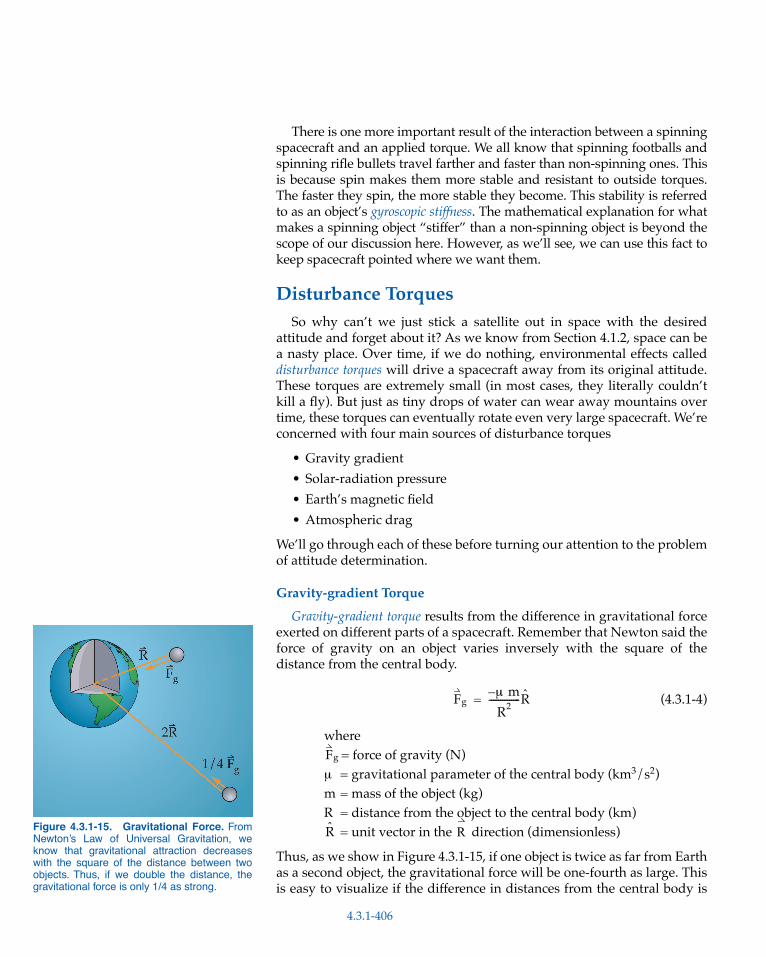
Figure 4.3.1-15. Gravitational Force. FromNewton’s Law of Universal Gravitation, weknow that gravitational attraction decreaseswith the square of the distance between twoobjects. Thus, if we double the distance, thegravitational force is only 1/4 as strong.
There is one more important result of the interaction between a spinningspacecraft and an applied torque. We all know that spinning footballs andspinning rifle bullets travel farther and faster than non-spinning ones. Thisis because spin makes them more stable and resistant to outside torques.The faster they spin, the more stable they become. This stability is referredto as an object’s gyroscopic stiffness. The mathematical explanation for whatmakes a spinning object “stiffer” than a non-spinning object is beyond thescope of our discussion here. However, as we’ll see, we can use this fact tokeep spacecraft pointed where we want them.
Disturbance TorquesSo why can’t we just stick a satellite out in space with the desired
attitude and forget about it? As we know from Section 4.1.2, space can bea nasty place. Over time, if we do nothing, environmental effects calleddisturbance torques will drive a spacecraft away from its original attitude.These torques are extremely small (in most cases, they literally couldn’tkill a fly). But just as tiny drops of water can wear away mountains overtime, these torques can eventually rotate even very large spacecraft. We’reconcerned with four main sources of disturbance torques
• Gravity gradient
• Solar-radiation pressure
• Earth’s magnetic field
• Atmospheric drag
We’ll go through each of these before turning our attention to the problemof attitude determination.
Gravity-gradient Torque
Gravity-gradient torque results from the difference in gravitational forceexerted on different parts of a spacecraft. Remember that Newton said theforce of gravity on an object varies inversely with the square of thedistance from the central body.
(4.3.1-4)
where= force of gravity (N)
µ = gravitational parameter of the central body (km3/s2)m = mass of the object (kg)R = distance from the object to the central body (km)
= unit vector in the direction (dimensionless)
Thus, as we show in Figure 4.3.1-15, if one object is twice as far from Earthas a second object, the gravitational force will be one-fourth as large. Thisis easy to visualize if the difference in distances from the central body is
Fgµ m –
R
2
--------------R =
Fg
R R
4.3.1-406

Figure 4.3.1-16. Gravity Gradient. In thissimplified, dumbbell-shaped spacecraft, weshow that the gravitational force on the lowerpart is slightly greater than the force on theupper part, . The same effect happensin more conventionally shaped spacecraft dueto differences in internal mass distribution.
F1 F2>
very great, but it works the same way for very small differences. Imaginewe have a dumbbell-shaped spacecraft in Earth orbit. If the dumbbell ishanging vertically, as in Figure 4.3.1-16, the lower mass (m1) will have aslightly greater gravitational force on it than the higher mass (m2).
If m2 is directly above m1, nothing interesting happens. However, if thedumbbell gets displaced off vertical, as in Figure 4.3.1-17, the slightdifference between the gravitational forces on the two masses will createa torque on the spacecraft that will tend to restore it to vertical. This is fineif you want it to be vertical, but if you don’t, your control system mustcontinually fight against this torque. We can estimate the magnitude ofthis torque using
(4.3.1-5)
where
Tg = gravity-gradient torque (Nm)
µ = gravitational constant (km3/s2) = 3.986 × 10⁵ km3/s2 for Earth
IZ = spacecraft moment of inertia about the axis (where we assume IX = IY and IZ >> IX) (kg m2)
IY = spacecraft moment of inertia about the axis (kg m2)
θ = angle between the body axis and the local vertical
This equation tells us three important things about the gravity-gradient effect
• It decreases with the cube of the distance—for example, by going from a 500-km-altitude orbit (R = 6878 km) to a 1000-km-altitude orbit (R = 7378 km) the torque reduces by almost 20%
• It depends on the difference between moments of inertia in the axis and – plane; thus, for a homogenous spacecraft with Ix = Iy = Iz the effect is zero
Tg3µ
2R3--------- IZ IY– 2θ( )sin=
Z
Y
Z
Figure 4.3.1-17. Gravity-gradient Torque. The slight difference in gravitational forcebetween the upper and lower part of a spacecraft will tend to rotate the spacecraft to vertical,with its long axis pointed to Earth.
ZX Y
4.3.1-407

• It depends on the angle between the axis and local vertical—the greater the angle from local vertical, the greater the torque
Later in this section we’ll see how we can turn this sometimes annoyingeffect to our advantage.
Solar-radiation Pressure
Another source of disturbance torque for spacecraft comes from theSun. The Sun exerts an ever-so-slight force called solar-radiation pressureon exposed surfaces. We’re used to being warmed by the Sun, tanned bythe Sun, and even burned by the Sun, but pushed by the Sun? Yes. Oneway to think about sunlight (or any light for that matter) is as tinybundles of energy called photons. In one of those seeming paradoxes ofmodern physics, we say these photons are massless (thus, they can travelat the speed of light), but they do have momentum. As photons strike anyexposed surface, they transfer this momentum to the surface. Why can’twe feel this force when we hold our hand up to the Sun? Because thisforce is very, very small. We can estimate the force using
(4.3.1-6)
whereF = force on a surface (N)Fs = solar constant = 1358 W/m2 at Earth’s orbit around the Sunc = speed of light = 3 × 10⁸ m/sAs= illuminated surface area (m2)r = surface reflectance (where r = 1 for a perfect reflector and 0 for
a perfect absorber) (unitless)I = incidence angle to the Sun (deg)
The force exerted on even a very large spacecraft with ten squaremeters of surface (assuming perfect reflectance) is only 9 x 10⁻⁵ N (2 x 10⁻⁵
lbf)! We assume this force acts at the center of pressure for the surface. Themoment arm is the distance from the center of pressure to the spacecraft’scenter of mass. We find the resulting torque by multiplying this forcetimes the moment arm (T = F × d). Even with a 1 m moment arm, theresulting solar pressure torque is only 9 × 10⁻⁵ Nm. So why worry aboutit? Over time, even this tiny force, acting unevenly over different parts ofthe spacecraft, especially large areas like solar panels, can cause problemsfor spacecraft needing precise pointing. In Section 4.2.1 we saw how weharnessed this small force to propel large solar sails.
Magnetic Torque
A third source of disturbance torque comes from Earth’s magneticfield. As we learned in Section 4.1.2, because of the impact of chargedparticles in space, the surface of a spacecraft can develop a charge of itsown giving it a distinct dipole—north/south ends, like a compass. Just as
Z
F Fsc
------ As 1 r+( ) Icos=
4.3.1-408

a compass needle rotates to align with Earth’s magnetic field, the dipole-charged spacecraft will similarly try to rotate as it passes through themagnetic field. The size of this magnetic torque depends on the spacecraft’seffective magnetic dipole and the local strength of Earth’s magnetic field.We estimate this from
T = D B (4.3.1-7)
where T = torque on a spacecraft (Nm)D = spacecraft dipole (amp-m2)B = local magnetic field’s strength (tesla), which varies with
altitude (R = distance to Earth’s center) and latitude. Earth’s magnetic moment, M, is about 7.99 × 10¹⁵ tesla-m3. At the poles, B = 2M/R3. At the equator, B = M/R3. (tesla = kg/amp-s2)
Magnetic torque is a big concern for operators of small satellites in low,polar orbit but hardly noticeable for large spacecraft in geostationary orbit.Later, we’ll see how we can create a large dipole on purpose to use thistorque as an attitude actuator.
Aerodynamic Drag
The last disturbance torque we have to worry about is drag. As we sawin Section 4.1.2, in low-Earth orbit the atmosphere applies a drag force toa vehicle, eventually causing it to re-enter the atmosphere and burn up. InSection 4.1.7 we introduced the drag force as
Fdrag = ρ V2 CD A (4.3.1-8)
whereFdrag= force of drag (N)ρ = atmospheric density (kg/m3)V = velocity (m/s)CD= drag coefficient (unitless)A = impacted area (m2)
Because parts of a spacecraft may have different drag coefficients (solarpanels, for example, act like big sails), drag forces on different parts of thespacecraft can also differ. This difference, along with the distancebetween the center of pressure (where the drag acts) and the center ofmass, causes a drag torque. A spacecraft designer can do little to preventthis torque (short of moving the spacecraft to a higher orbit), so again thecontrol system must be designed to deal with it.
Spacecraft Attitude SensorsAs we’ve seen, an essential element of closed-loop control systems is a
device that can watch what’s happening to the system and report this
12---
4.3.1-409
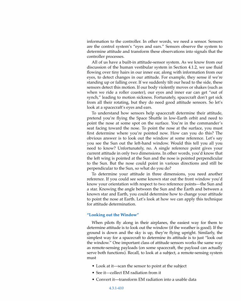
information to the controller. In other words, we need a sensor. Sensorsare the control system’s “eyes and ears.” Sensors observe the system todetermine attitude and transform these observations into signals that thecontroller processes.
All of us have a built-in attitude-sensor system. As we know from ourdiscussion of the human vestibular system in Section 4.1.2, we use fluidflowing over tiny hairs in our inner ear, along with information from oureyes, to detect changes in our attitude. For example, they sense if we’restanding up or falling over. If we suddenly tilt our head to the side, thesesensors detect this motion. If our body violently moves or shakes (such aswhen we ride a roller coaster), our eyes and inner ear can get “out ofsynch,” leading to motion sickness. Fortunately, spacecraft don’t get sickfrom all their rotating, but they do need good attitude sensors. So let’slook at a spacecraft’s eyes and ears.
To understand how sensors help spacecraft determine their attitude,pretend you’re flying the Space Shuttle in low-Earth orbit and need topoint the nose at some spot on the surface. You’re in the commander’sseat facing toward the nose. To point the nose at the surface, you mustfirst determine where you’re pointed now. How can you do this? Theobvious answer is to look out the window at some reference. Let’s sayyou see the Sun out the left-hand window. Would this tell you all youneed to know? Unfortunately, no. A single reference point gives yourcurrent attitude in only two dimensions. In other words, you’d know thatthe left wing is pointed at the Sun and the nose is pointed perpendicularto the Sun. But the nose could point in various directions and still beperpendicular to the Sun, so what do you do?
To determine your attitude in three dimensions, you need anotherreference. If you could see some known star out the front window you’dknow your orientation with respect to two reference points—the Sun anda star. Knowing the angle between the Sun and the Earth and between aknown star and Earth, you could determine how to change your attitudeto point the nose at Earth. Let’s look at how we can apply this techniquefor attitude determination.
“Looking out the Window”
When pilots fly along in their airplanes, the easiest way for them todetermine attitude is to look out the window (if the weather is good). If theground is down and the sky is up, they’re flying upright. Similarly, thesimplest way for a spacecraft to determine its attitude is to just “look outthe window.” One important class of attitude sensors works the same wayas remote-sensing payloads (on some spacecraft, the payload can actuallyserve both functions). Recall, to look at a subject, a remote-sensing systemmust
• Look at it—scan the sensor to point at the subject
• See it—collect EM radiation from it
• Convert it—transform EM radiation into a usable data
4.3.1-410

Figure 4.3.1-18. Earth Sensors. As theirname implies, Earth sensors use Earth as atarget for determining spacecraft attitude.Sensors focus either on the gross direction ofEarth or on narrower (and more accurate)parts of Earth, such as the horizon.
Figure 4.3.1-19. Sun Sensor. A Sun sensordetermines spacecraft attitude by finding thedirection of the Sun with respect to the bodyframe. Like Earth sensors, this sensor can onlygive a 2-dimensional fix on attitude withoutanother point of reference.
Figure 4.3.1-20. Star Sensor. A star sensordetermines a spacecraft’s attitude with respectto the known orientation of certain, bright stars.
• Process it—turn data into usable information
When it comes to remote sensing for attitude determination, threemain subjects are available for reference—Earth, the Sun, and the Stars.This gives us three classes of “out-the-window” sensors
• Earth sensors
• Sun sensors
• Star sensors
All these sensors work in pretty much the same way as other remote-sensing devices. Typically, they are attached to the spacecraft so thespacecraft must rotate to bring the subject into the sensor’s field of view orrely on “targets of opportunity” that will routinely go in and out of the fieldof view. Similar to a telescope or camera, EM radiation from the primarysubject enters through a lens and focuses on solid state detectors, such asthe charged-coupled devices. The sensor’s accuracy depends on howprecisely it can discriminate the target, or portion of the target, and howmuch onboard processing it can accomplish.
In low-Earth orbit, Earth fills a big portion of the sky. Earth sensors canroughly indicate the “down” direction by simply discriminating whereEarth is with respect to the rest of the sensor’s field of view. Atgeostationary altitude, the angular radius of Earth is about 10°, so asensor that can find Earth is at least accurate to within that amount. Touse Earth as a more accurate method of attitude determination, a sensormust focus only on one small part. Conveniently, sensors can detectEarth’s horizon by focusing on a narrow band of EM radiation emitted bycarbon dioxide, CO2, in the atmosphere, as shown in Figure 4.3.1-18.These Earth-horizon sensors can be as much as ten times more accuratethan a simple Earth detector.
Sun sensors, the most widely used for spacecraft attitude, are similar infunction to Earth sensors. As the name implies, a Sun sensor finds the Sunand determines its direction with respect to the spacecraft-body frame, asshown in Figure 4.3.1-19. By their nature, Earth and Sun sensors can giveaccurate information about attitude in only two dimensions. For example,this means an Earth or Sun sensor can measure pitch and roll relative to thehorizon, but not yaw; or pitch and yaw but not roll, etc.
A more accurate 2-axis reference is a star sensor. As Figure 4.3.1-20shows, star sensors measure a spacecraft’s attitude with respect to knownstar locations. Then they compare these measurements to accurate mapsof the brightest stars stored in the spacecraft’s memory. The anglebetween the known star’s position and a reference axis on the spacecraft,θ, then helps determine the spacecraft’s inertial attitude. By using two ormore star sensors located around a spacecraft (or by taking multiplemeasurements with the same sensor), the system can determine itsattitude in three dimensions.
As we mentioned, each of these sensors provides only a 2-D reference.To determine attitude in three dimensions, we often use two or moresensors together. For example, onboard computers can combine data
4.3.1-411
from an Earth sensor with Sun-sensor data to get a 3-D, accurate fix. Aswe’ll see, all of these sensors can also work with a spacecraft’s “ears”—gyroscopes and magnetometers.
Gyroscopes
Gyroscopes, like our inner ear, can determine attitude and changes inattitude, directly, without needing to look out the window. The simplesttype of gyroscope is a spinning mass. As we know, any spinning mass hasangular momentum that is conserved. By using this basic principle, wecan use the gyroscope to detect a spacecraft’s angular motion. Two basicprinciples of gyros make them useful as attitude sensors
• With no torques, their angular momentum is conserved—they always point in the same direction in inertial space
• With torque applied, they precess in a predictable direction and amount
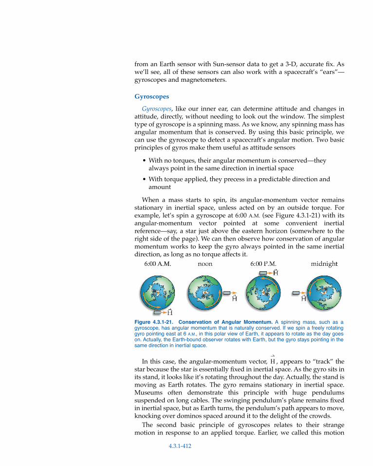
When a mass starts to spin, its angular-momentum vector remainsstationary in inertial space, unless acted on by an outside torque. Forexample, let’s spin a gyroscope at 6:00 A.M. (see Figure 4.3.1-21) with itsangular-momentum vector pointed at some convenient inertialreference—say, a star just above the eastern horizon (somewhere to theright side of the page). We can then observe how conservation of angularmomentum works to keep the gyro always pointed in the same inertialdirection, as long as no torque affects it.
In this case, the angular-momentum vector, , appears to “track” thestar because the star is essentially fixed in inertial space. As the gyro sits inits stand, it looks like it’s rotating throughout the day. Actually, the stand ismoving as Earth rotates. The gyro remains stationary in inertial space.Museums often demonstrate this principle with huge pendulumssuspended on long cables. The swinging pendulum’s plane remains fixedin inertial space, but as Earth turns, the pendulum’s path appears to move,knocking over dominos spaced around it to the delight of the crowds.
The second basic principle of gyroscopes relates to their strangemotion in response to an applied torque. Earlier, we called this motion
Figure 4.3.1-21. Conservation of Angular Momentum. A spinning mass, such as agyroscope, has angular momentum that is naturally conserved. If we spin a freely rotatinggyro pointing east at 6 A.M., in this polar view of Earth, it appears to rotate as the day goeson. Actually, the Earth-bound observer rotates with Earth, but the gyro stays pointing in thesame direction in inertial space.
H
4.3.1-412
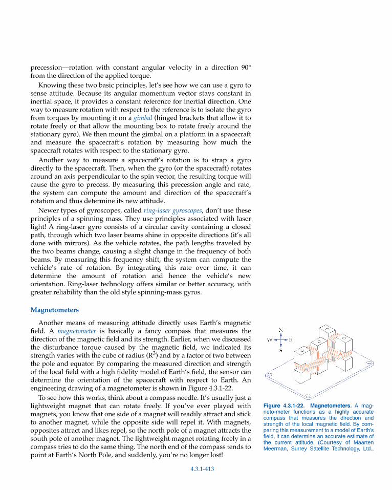
Figure 4.3.1-22. Magnetometers. A mag-neto-meter functions as a highly accuratecompass that measures the direction andstrength of the local magnetic field. By com-paring this measurement to a model of Earth’sfield, it can determine an accurate estimate ofthe current attitude. (Courtesy of MaartenMeerman, Surrey Satellite Technology, Ltd.,
precession—rotation with constant angular velocity in a direction 90°from the direction of the applied torque.
Knowing these two basic principles, let’s see how we can use a gyro tosense attitude. Because its angular momentum vector stays constant ininertial space, it provides a constant reference for inertial direction. Oneway to measure rotation with respect to the reference is to isolate the gyrofrom torques by mounting it on a gimbal (hinged brackets that allow it torotate freely or that allow the mounting box to rotate freely around thestationary gyro). We then mount the gimbal on a platform in a spacecraftand measure the spacecraft’s rotation by measuring how much thespacecraft rotates with respect to the stationary gyro.
Another way to measure a spacecraft’s rotation is to strap a gyrodirectly to the spacecraft. Then, when the gyro (or the spacecraft) rotatesaround an axis perpendicular to the spin vector, the resulting torque willcause the gyro to precess. By measuring this precession angle and rate,the system can compute the amount and direction of the spacecraft’srotation and thus determine its new attitude.
Newer types of gyroscopes, called ring-laser gyroscopes, don’t use theseprinciples of a spinning mass. They use principles associated with laserlight! A ring-laser gyro consists of a circular cavity containing a closedpath, through which two laser beams shine in opposite directions (it’s alldone with mirrors). As the vehicle rotates, the path lengths traveled bythe two beams change, causing a slight change in the frequency of bothbeams. By measuring this frequency shift, the system can compute thevehicle’s rate of rotation. By integrating this rate over time, it candetermine the amount of rotation and hence the vehicle’s neworientation. Ring-laser technology offers similar or better accuracy, withgreater reliability than the old style spinning-mass gyros.
Magnetometers
Another means of measuring attitude directly uses Earth’s magneticfield. A magnetometer is basically a fancy compass that measures thedirection of the magnetic field and its strength. Earlier, when we discussedthe disturbance torque caused by the magnetic field, we indicated itsstrength varies with the cube of radius (R3) and by a factor of two betweenthe pole and equator. By comparing the measured direction and strengthof the local field with a high fidelity model of Earth’s field, the sensor candetermine the orientation of the spacecraft with respect to Earth. Anengineering drawing of a magnetometer is shown in Figure 4.3.1-22.
To see how this works, think about a compass needle. It’s usually just alightweight magnet that can rotate freely. If you’ve ever played withmagnets, you know that one side of a magnet will readily attract and stickto another magnet, while the opposite side will repel it. With magnets,opposites attract and likes repel, so the north pole of a magnet attracts thesouth pole of another magnet. The lightweight magnet rotating freely in acompass tries to do the same thing. The north end of the compass tends topoint at Earth’s North Pole, and suddenly, you’re no longer lost!
4.3.1-413

Use of magnetometers is limited by the strength of the field, makingthem more useful in low-Earth orbit than at geostationary altitude. Thesensor accuracy depends on the accuracy of the field model. Even so, theyoffer a relatively inexpensive sensor that can deliver an independentreference from the other sensors we’ve discussed.
Global Positioning System (GPS)
The newest attitude sensor to emerge on the scene is the “differential”Global Positioning System (GPS). GPS is a constellation of 24 satellites inhigh Earth orbit (12-hour period) designed and deployed by the U.S. AirForce to provide world-wide position, velocity, and time information.Clever engineers figured that by placing two GPS receivers some distanceapart on a vehicle, and carefully measuring the difference between thetwo signals, they could determine a vehicle’s attitude. This attitude-determination technique may offer a relatively inexpensive, independentsystem for spacecraft in low-Earth orbits.
Spacecraft Attitude ActuatorsAfter we’ve determined what our spacecraft’s attitude is, we need to
know how to change it. For example, we may need to compensate fordisturbance torques or rotate the spacecraft to point at a new subject. Aswe’ve seen, applying a torque changes a vehicle’s attitude. That’s why weneed actuators. Actuators provide “torque on demand” to rotate a space-craft as needed to take pictures, downlink data, or meet other missionrequirements.
Many types of attitude actuators are available to spacecraft designers.Just as several different types of sensors often work together to accuratelymeasure attitude, typically two or more types of actuators combine toapply torque to achieve a desired attitude. For simplicity, we’ll discusseach type of actuator separately.
We can conceptually divide actuator types into two general classes,passive and active. Passive actuators operate more or less open loop. Inother words, after the spacecraft is in the desired attitude, passiveactuators will keep it there with little or no additional torques needed.Active actuators, on the other hand, require continuous feedback andadjustment. As you would expect, passive actuators typically can’t reachthe same level of accuracy as active ones; however, in many cases, they’regood enough. We’ll look at three types of passive actuators
• Gravity-gradient stabilization• Spin stabilization• Dampers
and three types of active actuators
• Thrusters• Magnetic torquers• Momentum-control devices
4.3.1-414

Figure 4.3.1-23. Gravity-gradient Stabiliza-tion. Some spacecraft take advantage of thegravity-gradient torque to keep them oriented ina local vertical, or “downward,” attitude. Usually,they maximize this effect by deploying a smallmass at the end of a very long boom. Thisartist’s conception of the PicoSAT spacecraftshows it to scale with a 6-m-long deployableboom and a small mass on the end. (Courtesyof Surrey Satellite Technology, Ltd., U.K.)
Figure 4.3.1-24. Spin Stabilization. Aspinning spacecraft keeps its angular-momentum vector fixed in inertial space.
Figure 4.3.1-25. Spin Stabilization Isn’tMuch Good for Earth Pointing. Because spinstabilized spacecraft have fixed pointing withrespect to inertial space, they aren’t a goodchoice for Earth-pointing missions. During partof the orbit, they may point toward Earth butduring other parts of the orbit, they’ll point away.
Gravity-gradient Stabilization
The first type of passive actuator takes advantage of the gravity-gradient disturbance torque discussed earlier. We can exploit this “free”torque to keep a spacecraft oriented in a local vertical, or “downward,”orientation. Fortunately, a spacecraft doesn’t have to be shaped like adumbbell to take advantage of this effect. For example, why do we seeonly one face of the Moon and never the mysterious “dark side?” Becauseof uneven distribution of mass within the Moon’s crust, it’s in a gravity-gradient-stabilized attitude with respect to Earth. However, to maximizethe effect of this cheap and reliable attitude actuator, spacecraft willusually deploy weighted booms to create a more dumbbell-like shape.Figure 4.3.1-23 shows an artist’s conception of the PicoSAT spacecraftusing a 6 m deployable boom.
Gravity-gradient attitude control offers a simple, reliable, inexhaustible(as long as there’s gravity) system with no moving parts. However, it hasa few drawbacks
• Control of only two axes—pitch and roll but not yaw• Limited accuracy—depending on the spacecraft’s moments of
inertia, downward pointing accuracy is only about ±10°• Only effective in low-Earth orbit—because gravity varies with the
square of the distance, it’s not very effective beyond LEO
Despite these disadvantages, gravity-gradient-controlled spacecraft havebeen used effectively on a variety of missions.
Spin Stabilization
Earlier we saw that a spinning mass has unique gyroscopic properties.A spin-stabilized spacecraft takes advantage of the conservation of angularmomentum to maintain a constant inertial orientation of one of its axes.Because the angular-momentum vector, , of a spinning mass is fixed ininertial space, the spacecraft tends to stay in the same inertial attitude, asshown in Figure 4.3.1-24.
Perhaps the best example of a spin-stabilized satellite is Earth. Thespinning Earth is essentially a giant gyroscope. Earth’s vector pointsout of the North Pole. This stays fixed in inertial space (except for aminor wobble), always pointed at the same place in the sky. When weobserve the motion of the stars at night, we see they all appear to rotatearound one star—the North Star. This occurs because Earth’s vectorpoints at the North Star!
Spin stabilization is useful, as long as we want our spacecraft to staypointed in the same inertial direction. However, usually we’re moreinterested in non-inertial pointing. For example, spin stabilization isn’tvery useful for pointing at Earth, as illustrated in Figure 4.3.1-25. Forthis reason, we mostly use it only during spacecraft deployment, whenthe natural gyroscopic stiffness we discussed earlier is useful to maintaina known orientation until the spacecraft is free from the launch vehicle.This spin is usually maintained through the first major maneuver,
H
HH
H
H
4.3.1-415

Figure 4.3.1-27. Dual-spin Communica-tion Spacecraft. Large geosynchronouscommunication spacecraft, such as the Satel-lite Business Systems spacecraft, shown here,make good use of dual-spin attitude control.(Courtesy of Hughes Space and Communica-tions Company)
providing a stiff, stable platform during a rocket firing. During high-thrust, orbit-insertion rocket firings, spin stabilization is often the onlytechnique that can efficiently keep the spacecraft stable.
One way to avoid Earth-pointing limitations of spin stabilization is touse a dual-spin system. Dual-spin systems also take advantage of theconstant angular momentum vector of a spinning mass. These systemsconsist of an inner cylinder called the “de-spun” section, surrounded by anouter cylinder that is spinning at a high rate. The outer cylinder providesoverall spacecraft stability. The word “de-spun” is actually a misnomer.In fact, the “de-spun” section does spin, but at a much slower rate thanthe outer section. To allow for antenna and sensor pointing, the “de-spun” section spins at a rate to keep them pointed at Earth. For example,if a spacecraft is in geostationary orbit, the de-spun section rotates at“orbit rate” or once every 24 hours, keeping antennas or other sensorsfocused on Earth, as shown in Figure 4.3.1-26.
Of course, the need for independently spinning sections makes dual-spin spacecraft much more complex. Electrical and other connectionsmust run from the spun to the “de-spun” sections. Highly reliablebearings must allow the two sections to spin at different rates with littlefriction. Even with these inherent technical challenges, dual-spin has beena popular control option for large, geosynchronous, communicationspacecraft, such as the one shown in Figure 4.3.1-27.
Dampers
As mentioned earlier, we seldom use a single type of attitude actuatoralone. A damper is another actuator usually used in combination withothers for a complete system. Generally speaking, a damper is a devicethat changes angular momentum by absorbing energy. We know
Figure 4.3.1-26. Dual-spin Spacecraft. A dual-spin spacecraft uses the inherent stiffnessof a spinning outer section with a “de-spun” inner section that can independently point atEarth. The de-spun section turns at the orbital rate to keep sensors and antenna pointed atEarth.
4.3.1-416

Figure 4.3.1-28. A Simple SpacecraftDamper. Dampers “absorb” unwanted angularmomentum by converting the energy into fric-tion, in much the same way as the brakes in acar turn linear momentum into heat throughfriction. A ball inside a circular tube filled with aviscous fluid is one type of damper. As thespacecraft rotates, the ball moves through thefluid. The resistance produces heat, dissipat-ing the angular motion.
Figure 4.3.1-29. Thrusters. Thrusters arerockets that apply a force some distance awayfrom the center of mass, causing a torque thatrotates the spacecraft.
momentum is constant only as long as energy stays constant. If we add ortake away energy, momentum changes. As a spacecraft attitude actuator,dampers absorb unwanted momentum. Where does it go? When we hitthe brakes in a car, the linear momentum “goes” into heat produced byfriction between the brake pads and the disks or drums. Similarly,attitude dampers use friction or other means to convert angular-momentum energy into other forms.
One simple type of momentum damper consists of a small ball in acircular tube filled with highly viscous fluid, as illustrated in Figure 4.3.1-28. As a spacecraft rotates, some of its momentum is contained in the ballthat moves inside the tube. Friction between the ball and the fluid in thetube converts some of the momentum into heat that slowly dissipatesthroughout the spacecraft. Over time, the spacecraft can use this simpletechnique to absorb mechanical energy, slowing it’s rotation. Dampers areusually designed and oriented to reduce rotation about a specific axis. Inthis way, designers often use them in spinning spacecraft to removeunwanted “wobbles” in the spin axis.
Thrusters
All of the actuators we’ve discussed so far are passive, in that, once putin motion, they can more or less function in an open-loop mode, withlittle or no additional inputs. Now we’ll turn our attention to activeactuators. Thrusters are perhaps the simplest type of active actuator tovisualize. Thrusters are simply rockets that rely on “brute force” to rotatea spacecraft. By applying a balanced force with a pair of rockets onopposite sides of a spacecraft, we can produce a torque, as shown inFigure 4.3.1-29. By varying which thruster pair we use and how muchforce we apply, we can rotate a spacecraft in any direction.
Placing thrusters as far from the satellite’s center of mass as possiblegives them a larger moment arm and allows them to exert a greatertorque for a given force. This is evident from the important concept wesaw earlier. The greater the distance over which a force is applied, themore torque is delivered from the same force. However, as we learnedearlier, because of precession, when a spacecraft is already spinning, anyapplied torque in a direction other than the spin axis causes the spacecraftto rotate at constant velocity about an axis perpendicular to the torquedirection.
The biggest advantage of using thrusters is that they can produce a welldefined “torque on demand,” allowing the spacecraft to slew quickly fromone attitude to another. Unfortunately, the amount of propellant aspacecraft can carry limits their use. For short missions, such as thoseflown by the Space Shuttle, this limit is no problem. For longer missions(months or years), designers use thrusters only as a backup and for otherpurposes we’ll discuss later. We’ll explore basic principles of rocket scienceand propulsion system technologies in greater detail in Section 4.2.1.
4.3.1-417

Figure 4.3.1-30. Magnetic Torquers. A mag-netic torquer is an active spacecraft-attitudeactuator that takes advantage of the naturaltorque caused by Earth’s magnetic fieldinteracting with a magnet; it’s the same effectthat rotates a compass needle. Onboard, thesystem switches electromagnets on and off asneeded, pushing ”against” the magnetic fieldand producing the necessary torque.
Magnetic Torquers
A magnetic torquer is another type of actuator that takes advantage of anaturally occurring torque in the space environment. Earlier we looked atthe magnetic disturbance torque caused by the interaction of thespacecraft’s magnetic field due to surface charging with Earth’s magneticfield. We can use this effect in an active mode by creating powerfulonboard magnets and switching them on and off as needed to rotate“against” Earth’s magnetic field. Magnetic torquers are simplyelectromagnets produced by running an electrical current through a loopof wire onboard. Like a compass needle, this electromagnet tries to alignwith Earth’s magnetic field, dragging the rest of the spacecraft with it, asseen in Figure 4.3.1-30.
Magnetic torquers offer a relatively cheap and simple way to control aspacecraft’s attitude. Furthermore, because they need only electricalpower to run, they’re inexhaustible—unlike thrusters. Unfortunately,their effectiveness depends directly on the strength of Earth’s magneticfield, so they become less useful in higher orbits. Also, because the fieldstrength varies by a factor of two between the equator and the poles, theyare most useful in highly inclined orbits. Even so, they are an importantsecondary means of attitude control used on many LEO spacecraft.
Momentum-control Devices
The most common actuator for spacecraft attitude control is a family ofsystems that all rely on angular momentum. These momentum-controldevices actively vary the angular momentum of small, rotating masseswithin a spacecraft to change its attitude. How can this work? If youstand on a turntable, holding a spinning bicycle wheel at arm’s length,you can cause yourself to rotate by tilting the bicycle wheel to the left orright. This works because total angular momentum of a system is alwaysconserved. As the bicycle wheel rotates one way, you rotate another tocompensate, keeping the total angular momentum constant, as you cansee in Figure 4.3.1-31.
Let’s look at where this attitude change comes from. From Equation(4.3.1-2), we know angular momentum is the product of an object’s massmoment of inertia, I, and its angular velocity, .
(4.3.1-2)
Note that a large mass (high I) spinning at a relatively slow speed (low )can have exactly the same angular momentum as a small mass (low I)spinning at a much higher rate (high ). If we consider a spacecraft andall mass inside it to be one system, we can control where the spacecraftpoints by changing the angular momentum (rate and direction of spin) ofa small spinning mass inside. Three approaches to momentum-controldevices are in wide use
• Biased momentum systems—“Momentum wheels” that typically rely on a single wheel with a large, fixed momentum to provide
Ω
H IΩ=
Ω
Ω
4.3.1-418

Figure 4.3.1-32. Biased Momentum Sys-tems. We use momentum wheels in biasedmomentum systems. They typically rely on asingle wheel with a large, fixed (“biased”)momentum to provide overall stiffness. Thewheel speed gradually increases to absorb dis-turbance torques. (Courtesy of Ball Aerospace& Technologies Corporation)
Figure 4.3.1-33. Reaction Wheels. Reactionwheels are part of a zero-bias system that usesthree independent wheels, one along eachaxis, normally with zero or nearly zeromomentum. To rotate the spacecraft or absorbdisturbance torques, one or more wheels beginto spin. Often, designers add a fourth wheel,skewed with respect to the other three, forredundancy.
overall stiffness. The wheel’s speed gradually increases to absorb disturbance torques.
• Zero-bias systems—“Reaction wheels” that rely on three or more wheels, normally with little or no initial momentum. Each wheel spins independently to rotate the spacecraft and absorb disturbance torques.
• Control-moment gyroscopes— rely on three or more wheels, each with a large, fixed momentum. The wheels are mounted on gimbals, rotating the wheels about their gimbals changes the spacecraft orientation.
Biased momentum systems are the simplest type of momentum controldevice. In operation, these systems use one or two continually spinningmomentum wheels, each with a large, fixed momentum. (They are “biased”toward having a particular, set momentum, hence the name). Becausethey are always spinning, they give the spacecraft a large angular-momentum vector, fixed in inertial space. This is exactly the same conceptused by spin-stabilized spacecraft, discussed earlier. Only, in this case, in-stead of spinning the whole spacecraft, we only spin a small wheel insidethe spacecraft to achieve the same effect, as illustrated in Figure 4.3.1-32.
In contrast, reaction wheels are a type of zero-bias system, because theirnormal momentum is at or near zero (no bias). Typically, an attitudecontrol system uses at least three separate reaction wheels, oriented atright angles to each other, as seen in Figure 4.3.1-33. Often, a fourth wheel
Figure 4.3.1-31. Bicycle Wheels in Space? You can do a simple experiment to see oneway spacecraft control their attitude. By standing on a turntable and holding a spinningbicycle wheel, as shown in the left-hand photograph, you can change direction (yourattitude). You’d simply apply a small torque to the wheel by slightly tilting the wheel to oneside, as shown in the right-hand photograph.
4.3.1-419

Figure 4.3.1-35. Reaction Wheels forAccurate Pointing. The Hubble SpaceTelescope observes many interstellar objectsat such long distances that it must point veryaccurately. To be this accurate, it relies on veryaccurate reaction wheels. (Courtesy ofNASA/Johnson Space Center)
is skewed to the other three for redundancy. When the spacecraft needs torotate to a new attitude, or to absorb a disturbance torque, the systemspins one or more of these wheels. To see how this works, let’s stepthrough what happens to the relationship between a reaction wheel andthe overall spacecraft momentum.
First of all, recognize that without any external torque, the totalangular momentum of the spacecraft (including the reaction wheels) isconserved (and usually maintained at or near zero). Thus, the angularmomentum of the spacecraft plus the angular momentum of the reactionwheels must add to a constant vector quantity. Now, imagine one of thereaction wheels begins to spin using a motor. As the wheel’s spin rateincreases, its angular momentum also increases. But the total angularmomentum of the wheel and spacecraft must always sum to a constantvalue. So what happens to the spacecraft?
Let’s look at a more specific example to get a better idea. We canexpress the total angular momentum of the spacecraft (including reactionwheels) as
(4.3.1-9)
where= total angular momentum of the spacecraft (kg m2/s)
= angular momentum of just the spacecraft (kg m2/s)
= angular momentum of the reaction wheels (kg m2/s)
[Note: This relationship is vector addition, so !]If a reaction wheel spins faster, its angular momentum increases by an
amount . Because the total angular momentum must stay constant,the spacecraft’s angular momentum must automatically decrease tocompensate by an amount . The vector increase in the reactionwheel’s momentum must exactly equal the decrease in the spacecraft’smomentum, or , to keep a constant total. Figure 4.3.1-34shows these relationships. To conserve momentum, the spacecraft musteither slow its rotation or start rotating in the opposite direction. In eithercase, the spacecraft’s attitude has changed simply by spinning a smallmass faster inside.
Three reaction wheels can deliver precise control of a spacecraft’sattitude in all three axes. Unfortunately, as with any mechanism withmoving parts, they can be complex, expensive, and have a limited opera-tional lifetime. Despite these limitations, they remain the primary choicefor attitude control on large, modern spacecraft requiring very accuratepointing, such as the Hubble Space Telescope shown in Figure 4.3.1-35.
The final type of momentum-control device is the control-momentgyroscope (CMG). A CMG consists of one or more spinning wheels, eachmounted on gimbals that allow them to rotate freely in all directions.Recall that reaction wheels change momentum by changing magnitudeonly (spinning faster or slower). CMGs change momentum by changingtheir magnitude and direction (physically rotating the spinning wheel).
HTOT HS C⁄ HRW+=
HTOT
HS C⁄
HRW
HTOT HS C⁄ HRW+≠
∆HRW
∆HS C⁄
∆HRW ∆– HS C⁄=
4.3.1-420

Figure 4.3.1-36. A Control Moment Gyro-scope (CMG) in Space. CMGs can vary themagnitude and direction of their angularmomentum, allowing for much higher slewrates and making possible efficient attitudecontrol on very large platforms, such as theSkylab Space Station shown here. (Courtesyof NASA/Johnson Space Center)
Again, because the total angular momentum of the system must beconserved, as the momentum of a CMG changes in one way, thespacecraft will rotate in the other to compensate. CMGs provide pointingaccuracy equivalent to reaction wheels but offer much higher slew ratesand are especially effective on very large platforms, such as the SkylabSpace Station shown in Figure 4.3.1-36.
One important limitation of all momentum control devices is thepractical limit on how fast a given wheel can spin. In operation, all ofthese systems must gradually spin faster and faster to rotate thespacecraft and absorb disturbance torques. Eventually, a wheel will bespinning as fast as it can, without damaging bearings or othermechanisms. At this point, the wheel is “saturated,” meaning it hasreached its design limit for rotational speed. When this happens, thewheels must “de-saturate” through a process known as “momentumdumping.” Momentum dumping is a technique for decreasing the angularmomentum of a wheel by applying a controlled torque to the spacecraft.The wheel can absorb this torque in a way that allows it to reduce its rateof spin. Of course, this means the spacecraft needs some independentmeans of applying an external torque. For this reason, on all spacecraftusing momentum control devices, designers use either magnetic torquersor thrusters (or both) to allow for momentum dumping.
The ControllerSo far, we’ve looked at the dynamics of rotating systems to understand
how torque affects a spacecraft’s angular momentum, including theenvironmental sources for disturbance torques. We then looked at thevarious types of sensors used to measure attitude. Finally, we discussedthe different types of actuators, passive and active, used to generatetorques that allow us to freely change a spacecraft’s attitude. Now we can
Figure 4.3.1-34. Reaction Wheels in Operation. The total angular momentum of aspacecraft system is the sum of the spacecraft’s momentum plus the momentum of eachreaction wheel. In this example, we start with a non-rotating spacecraft that has zero totalangular momentum. To rotate the spacecraft in one direction, a reaction wheel is spun up in theopposite direction, such that the total angular momentum of the system stays constant.
4.3.1-421

put the entire attitude determination and control subsystem together bylooking at the “brains” of the operation—the controller.
The controller’s job is to generate commands for the actuators to makethe spacecraft point in the right direction based on mission requirementsfor accuracy and slew rate. To use the information from sensors andcontinuously adjust actuator commands, the controller must be smart. Ithas to know what’s happening and decide what to do next. To do thisright, the controller has to keep track of
• What’s happening now
• What may happen in the future
• What happened in the past
Knowing what’s happening now is pretty easy—the controller simplyasks the sensors to find the current attitude. It then compares this to thedesired attitude. The difference between the measured and desiredattitude is the error signal. Based on this error signal, the controller steers inthe direction of the proper orientation. That is, if the attitude is 10° off, thecontroller commands a 10° change. This is known as proportional controland is used in some form in virtually all closed-loop control systems.
However, predicting what’s going to happen and remembering what’shappened in the past can be just as important. For example, if you need tostop at a stop sign, you need to know not only where you are, but alsohow fast you’re going, so you can hit the brakes in time. Similarly, to hitthe desired attitude, the spacecraft controller must monitor the attituderate, as well as the current attitude. For you calculus buffs, you mayrecognize this rate of change calculation as a derivative. In this case, byknowing the rate of change or “speed” of attitude, the controller can moreaccurately determine how to command the actuators to achieve betteraccuracy. This process is called derivative control.
Sometimes we can be more precise by keeping track of how close we’regetting to the desired result. One way to do this is for the controller tomonitor the angular difference between the measured and desiredattitude, ∆θ. When the spacecraft reaches the desired attitude, thisdifference, ∆θ, will be zero. If the system stops commanding the actuatorsat this point, the attitude will immediately begin to drift due todisturbance torques. A really smart controller, however, won’t just look atthe instantaneous ∆θ. Instead, it would keep a running tally, summing the∆θ over time. The result would always be some value other than zero andwould tell the controller how much torque to add in a “steady-state”mode to compensate for the disturbance torques. In calculus, this processis called integration, so we call this type of control integral control.Designers use it for highly accurate pointing.
Regardless of the exact scheme used, the controller combines itsmemory with its current measurements and an ability to predict futurebehavior to decide how to command the actuators. We can now completea block diagram of a spacecraft’s attitude-control system in Figure 4.3.1-37.
4.3.1-422

DCS (the attitude part of an AOCS) includes an or change spacecraft attitude in response to
st understand the model of system acecraft we must recognize that
direction of spin for a spinning and hence, change in angular
spinning object will cause city about an axis perpendicular to
t, over time, work to change its
pacecraft, determining attitude by ote-sensing payloads.
e changes in attitude because a
ttitude changes
Continued on next page
Figure 4.3.1-37. Attitude Determination and Control Subsystem (ADCS). A complete Acontroller, actuators, the spacecraft (“the plant”), and sensors that work together to maintaichanging mission requirements.
Section ReviewKey Concepts
To understand a spacecraft’s behavior or how it reacts to inputs, we mudynamics based on linear and rotational laws of motion. To rotate a sp• Angular momentum is always conserved• A torque describes the direction of a force couple applied to a system• A torque applied to a non-spinning object (or applied parallel to the
object) causes angular acceleration, which leads to angular velocity orientation
• A torque applied in a direction other than the direction of spin for a precession. This means it will begin to rotate at constant angular velothe torque direction.
A Spacecraft experiences many environmental disturbance torques thaattitude. These include
• Gravity gradient
• Magnetic
• Solar-radiation pressure
• Atmospheric drag
Sensors determine a spacecraft’s attitude
• Sun sensors, horizon sensors, and star sensors are the “eyes” of the s“looking out the window.” They work in much the same way as rem
• Gyroscopes are the “inner ears” of spacecraft. They can directly sensspinning mass has two important properties
–The angular momentum of a spinning mass is constant
–Torque applied to a spinning mass causes precession
• Ring-laser gyros measure the changing frequency of light to detect a
4.3.1-423

Section Review (Continu
References
Asimov, Isaac. Asimov’s Biographical ECompany, Inc., 1972.
Chetty, P.R.K. Satellite Power Systems: EWashington University Short Course
Chetty, P.R.K. Satellite Technology and McGraw-Hill, Inc., 1991.
Gere, James M., Stephen P. Timoshenko
Gonick, Larry and Art Huffman. The Ca
Gordon, J.E. Structures: Why Things Don
Holman, J.P. Thermodynamics. New York
Pitts, Donald R. and Leighton E. Sissom1977.
Wertz, James R. and Wiley J. Larson. SKluwer Academic Publishers, 1999.
Wertz, James R. [ed.] Spacecraft Attitude
Key Concepts (Continued)
• Magnetometers measure the dir
• Differential Global Positioning Sor more locations on a spacecra
Applying torques to the spacecraf
Passive attitude actuators include
• Gravity-gradient stabilization
• Spin stabilization
• Dampers
Active attitude actuators include
• Thrusters
• Magnetic torquers
• Momentum-control devices
–Zero-bias systems—momentum
–Bias momentum systems—rea
–Control moment gyros
The controller decides what commfrom sensors and an understandin
ed)
ncyclopedia of Science and Technology. Garden City, NJ: Doubleday and
nergy Conversion, Energy Storage, and Electronic Power Processing. George 1507. October, 1991.
Its Applications. THB Professional and Reference Books, New York, NY:
. Mechanics of Materials. Boston, MA: PWS Publishers, 1984.
rtoon Guide to Physics. New York, NY: Harper Perennial, 1991.
’t Fall Down. New York, NY: Da Capp Press, Inc., 1978.
, NY: McGraw-Hill Book Co., 1980.
. Heat Transfer. Schaum’s Outline Series. New York, NY: McGraw-Hill, Inc.,
pace Mission Analysis and Design. Third edition. Dordrecht, Netherlands:
Determination and Control. Netherlands: D. Reidel Publishing Co., Kluwer
ection and magnitude of Earth’s magnetic field to determine attitude
ystem (GPS) measures the difference between signals received at two ft to determine attitude
t requires spacecraft actuators. Actuators are either passive or active.
wheels
ction wheels
ands to send to active actuators based on current and historical data g of spacecraft rotational properties
4.3.1-424

Example 12-1
Problem Statement
Based on your experience in designing the FireSat payload, you’ve nowbeen put in charge of the attitude-control system. For the FireSatconstellation to provide continuous coverage, the center of the sensor’sFOV must not deviate from nadir by more than ±100 km. Determine thecorresponding attitude accuracy required. Given this accuracy, complete aconceptual design of the FireSat’s attitude-control subsystem using thesimplest available techniques. Draw a simple block diagram for yourresulting subsystem.
Problem Summary
Given: D = 100 kmh = 500 km (from Example 11-1)
Find: ψ, conceptual design of FireSat attitude control system
Conceptual Solution
1) Determine ψ, for the given D and h, using Equation (4.3.1-1)D = hψ
2) Complete a conceptual design of the FireSat’s attitude-control systemusing the simplest techniques.
3) Draw a simple block diagram for the subsystem.
Analytical Solution
1) Determine ψ, given D and h
ψ = 0.2 rad ψ = 11.459°
2) Complete a conceptual design of the FireSat’s attitude-control system,using the simplest techniques.
We could use almost an infinite number of possible control schemes toachieve modest pointing accuracy. Given that the spacecraft willoperate in LEO and must be mainly nadir pointing, the simplesttechnique would be gravity-gradient stabilization. The addition of a
ψDh----=
ψDh---- 100 km
500 km-------------------= =
4.3.1-425

short boom (2 m–3 m) with a small mass at the tip (~1 kg) shouldprovide enough gravity-gradient torque to keep the spacecraft nadirpointing. To ensure the payload is pointing “right side down,” a smallmagnetorquer could also be added. Three-axis attitude determinationcan be done using a simple sun sensor (2-axis) plus a magnetometer (3-axis).
3) Draw a simple block diagram for the subsystem.
Interpreting the Results
Given the computed attitude accuracy and the conceptual design of theFireSat’s attitude-control system, we can present the system blockdiagram, as shown above. As team players in the overall spacecraft design,we need to consider the corresponding requirements this particularsubsystem will have on other spacecraft subsystems. For example, using agravity-gradient boom will mean the structures and mechanisms must beable to accommodate its storage during launch and successful deploymenton orbit. Using a magnetorquer will place more demands on the electricalpower subsystem.
4.3.1-426

4.3.1-427