Embed Size (px)
Citation preview
International Journal of Science and Research (IJSR) ISSN (Online): 2319-7064
Index Copernicus Value (2013): 6.14 | Impact Factor (2013): 4.438
Volume 4 Issue 5, May 2015
www.ijsr.net Licensed Under Creative Commons Attribution CC BY
Control System and Automation of Smart Grid
Network
Punam Deotare1, Lalit Dole
2
Department of Computer Science &Engineering, G. H. Raisoni College of Engineering, Nagpur, Maharashtra, India
Abstract: Electrical system is the system that automates all several processes that were fall within the domain of Smart Grids and their
method. purpose of the Smart Grids are resource power i.e. distribution at a city or state level, that are to an extent autonomous in the sense
that they operate logically which reduce the manual operation in the scheme at small area. We figure a Smart electrical powerGrid that
mechanizes all the controlling operation include in power grid, using centralised server, we can divert the power supply to whichever area of
the city just with one tick of a knob. Also, we can divert power to fault creating area from a new source.With the Wide Area Network
interface we provide remote connectivity through attendant, term the World Wide Web on the internet. Thus we can control the grid with the
help of web browser and internet remote connectivity.
Keywords: electric smart grid, grid controlling scheme, energy management, central computer server, web page.
1. Introduction
Electricity being a very necessary part of life is found being
distributed over almost every part of country. The delivery of
electricity in come room over a „grid‟ known as the electric
power grid, which records each and all electric power line, and
distribution unit, right from the generating station to each and
every electric pole. This grid therefore is nothing but a mesh
reflecting the distribution of power over every area. To control
such a grid is a tedious job.
Controlling here includes witchings witches ON and OFF,
offering load shedding of shot period, super alteration method
in fault act location etc. of electricity in the mini delivery idea.
Process of Switching turning supply ON or OFF manually.
This is often required during maintenance work as well as
while re-establishing faults. As, fine power greedy country
like ours, load shedding is a shared wonder. This over consist
of switching. Diverting power is required when a major fault
occurs over a power line and hence electricity from another
grid or another part of the grid is drawn here i.e. diverted here
to continue supplying power to the consumers.
All such activities i.e. switching supply ON or OFF, as long as
load shedding is an difficult task may require the mechanical
switching in need site i.e. with the help of manually switch
power ON or OFF with the help of mechanical switches done
in electrical power contour. Equally diverting power is the
procedure which would demand a number of switching over
various two-way switches and this is certainly not a possible
way to do, regularly a need transpire. We plan to develop a
solution to automate these activity, where we can switch a
complete power grid, i.e. the complete power scheme of a city
by one federal attendant. We can switch on the power supply
ON or OFF just by one clicking button through the controlling
screen. We can redirect main power supply from another
distribution unit to whichever area we required. Here we work
on the function like online fault monitoring detection,
achieving load-shedding of whichever area, data record and
recovery, power diversion during major faults can be
performed from one central server only.
2. Block Diagram of Proposed System
The dominant server system that we plan to develop is a
comfort made schemes. It is alike to the UNIX ability comfort
and would effort on awareness. We plan to devolpe GUI for
leading and monitoring fault shelter using VB 6.0 software.
This attendant would be developed in „C‟. We were use „C‟ for
developing comfort is quite flexible when prepared in „C‟.
Besides, since this attendant would essential to communicate
with our hardware model through the serial port, we realized
that „C‟ is capable of providing a direct access and easy
programming with the serial ports RS232 during serial
communiqué. Thus it is discover that the all bulge are
wirelessly linked with server in planned system. In our system
we measured bulge that can be considered they are distribution
unit, feeder, substation, mini area and so on.
Figure 1: Block diagram of proposed system
So, we are going to develop the system that can demonstrate
capabilities like online remote fault detection, which will help
us in finding the exact location of any faults in the distribution
Paper ID: SUB153962 872
International Journal of Science and Research (IJSR) ISSN (Online): 2319-7064
Index Copernicus Value (2013): 6.14 | Impact Factor (2013): 4.438
Volume 4 Issue 5, May 2015
www.ijsr.net Licensed Under Creative Commons Attribution CC BY
power lines through feedback and relays for other features
which include diversion, providing load shedding and so on,
thus it can communicate with our server wirelessly and
controlled using merge server. Level of generating limitation
scheme logging, i.e. creating a Web page logging that can
communicate with the centralised server for frequent
parameters, like energy meter analysis, and frequent voltage
and current limitations will be achieve by our expedient. This
evidence will be connected wirelessly to our attendant, and a
permanent best ever will be made here for future position.
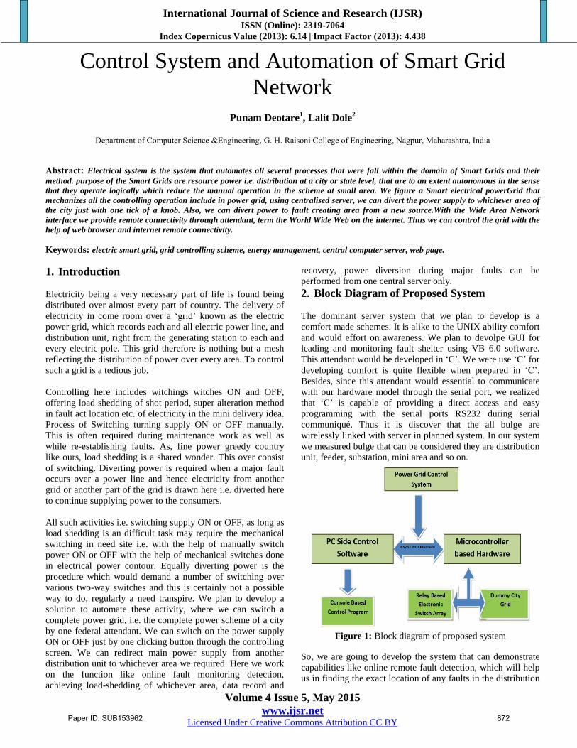
3. Architecture
3.1 Hardware Architecture
We intend to use 8051 microcontroller, which will act as the
brain of our project. We prefer microcontroller because it has
inbuilt UART for serial communiqué, four input/output ports,
intrinsic memory and timers. All these items used in our
project and will be employed via programming.
MAX 232 IC will be used to implement RS-232 protocol. It
acts as a medium of communiqué between the controller and
attendant or PC.
Relays work an important role in our project. They are
responsible for all the switching activities involved in our
project. Relays activate on 12v DC supply, which will be
attained straight from 12v adapter. Microcontroller 8051 and
other components work on 5v DC. For that it is essential to
transform 12v to 5v by mean of voltage regulator IC LM7805.
Figure 2: Hardware Architecture
3.2 Software Architecture
Here we are using the embedded “C” coding for controller
programming as it is simpler to code and easy to understand
using Kiel uVision4 and Flash magic is the software (for
burning the code into microcontroller board). For developing
the GUI i.e. fault monitoring screen and controlling screen we
use Visual basic 6.0 software and we resolve by mean of
Xpress PCB software for scheming the layout of main
controller board.
Paper ID: SUB153962 873
International Journal of Science and Research (IJSR) ISSN (Online): 2319-7064
Index Copernicus Value (2013): 6.14 | Impact Factor (2013): 4.438
Volume 4 Issue 5, May 2015
www.ijsr.net Licensed Under Creative Commons Attribution CC BY
4. Applications
Load shedding
High voltage grid control
Industrial automation
Electro, Hydraulic and pneumatic valve control
Robotic control and many more
Hotel power management
Street light management
Home automation.
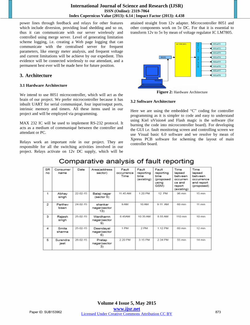
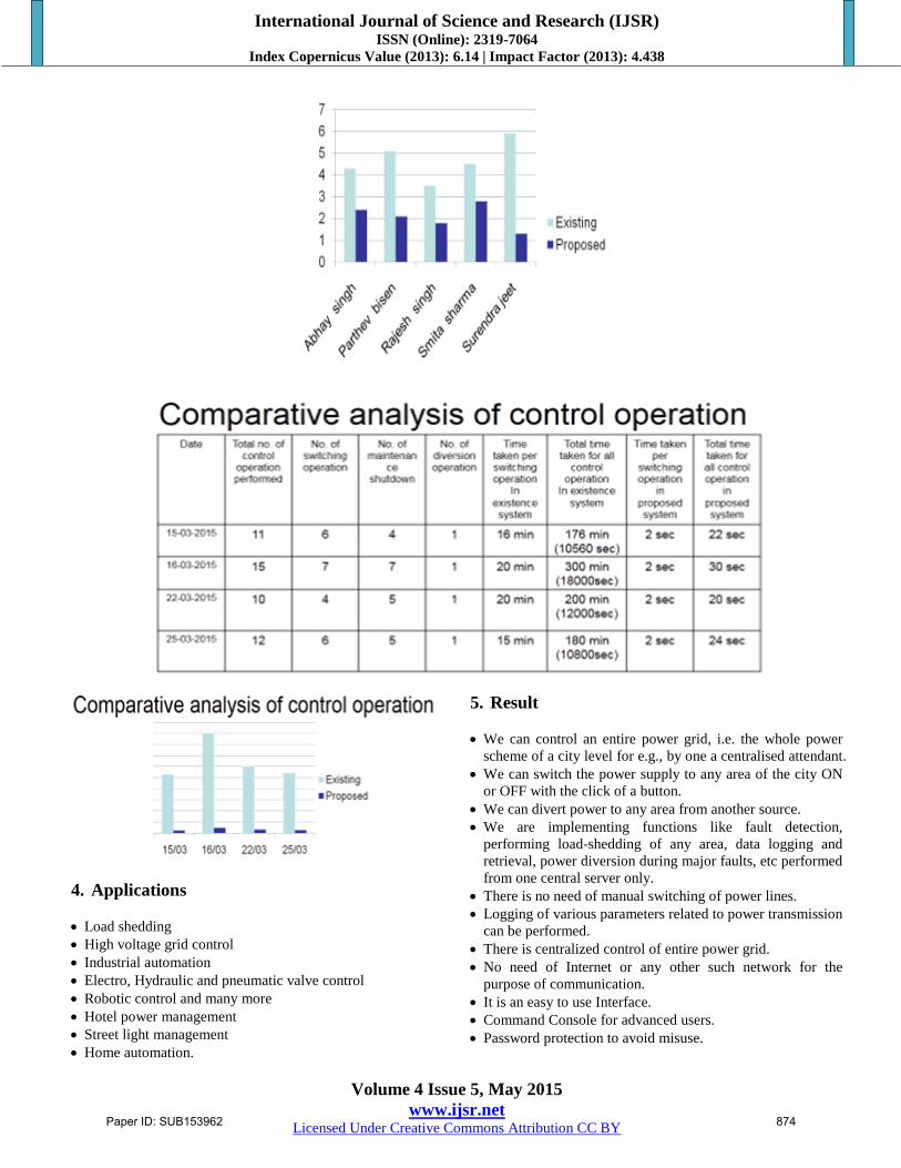
5. Result
We can control an entire power grid, i.e. the whole power
scheme of a city level for e.g., by one a centralised attendant.
We can switch the power supply to any area of the city ON
or OFF with the click of a button.
We can divert power to any area from another source.
We are implementing functions like fault detection,
performing load-shedding of any area, data logging and
retrieval, power diversion during major faults, etc performed
from one central server only.
There is no need of manual switching of power lines.
Logging of various parameters related to power transmission
can be performed.
There is centralized control of entire power grid.
No need of Internet or any other such network for the
purpose of communication.
It is an easy to use Interface.
Command Console for advanced users.
Password protection to avoid misuse.
Paper ID: SUB153962 874
International Journal of Science and Research (IJSR) ISSN (Online): 2319-7064
Index Copernicus Value (2013): 6.14 | Impact Factor (2013): 4.438
Volume 4 Issue 5, May 2015
www.ijsr.net Licensed Under Creative Commons Attribution CC BY
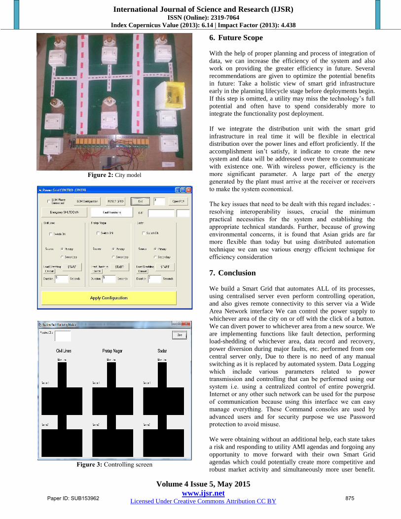
Figure 2: City model
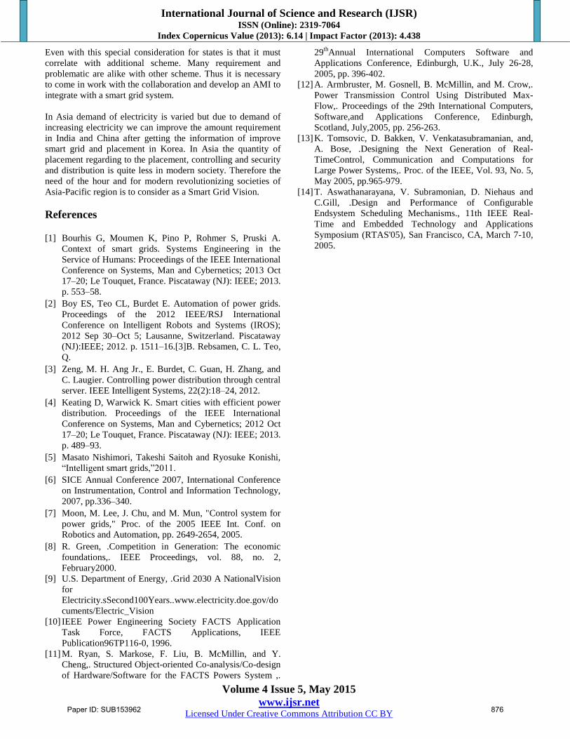
Figure 3: Controlling screen
6. Future Scope
With the help of proper planning and process of integration of
data, we can increase the efficiency of the system and also
work on providing the greater efficiency in future. Several
recommendations are given to optimize the potential benefits
in future: Take a holistic view of smart grid infrastructure
early in the planning lifecycle stage before deployments begin.
If this step is omitted, a utility may miss the technology‟s full
potential and often have to spend considerably more to
integrate the functionality post deployment.
If we integrate the distribution unit with the smart grid
infrastructure in real time it will be flexible in electrical
distribution over the power lines and effort proficiently. If the
accomplishment isn‟t satisfy, it indicate to create the new
system and data will be addressed over there to communicate
with existence one. With wireless power, efficiency is the
more significant parameter. A large part of the energy
generated by the plant must arrive at the receiver or receivers
to make the system economical.
The key issues that need to be dealt with this regard includes: -
resolving interoperability issues, crucial the minimum
practical necessities for the system and establishing the
appropriate technical standards. Further, because of growing
environmental concerns, it is found that Asian grids are far
more flexible than today but using distributed automation
technique we can use various energy efficient technique for
efficiency consideration
7. Conclusion
We build a Smart Grid that automates ALL of its processes,
using centralised server even perform controlling operation,
and also gives remote connectivity to this server via a Wide
Area Network interface We can control the power supply to
whichever area of the city on or off with the click of a button.
We can divert power to whichever area from a new source. We
are implementing functions like fault detection, performing
load-shedding of whichever area, data record and recovery,
power diversion during major faults, etc. performed from one
central server only, Due to there is no need of any manual
switching as it is replaced by automated system. Data Logging
which include various parameters related to power
transmission and controlling that can be performed using our
system i.e. using a centralized control of entire powergrid.
Internet or any other such network can be used for the purpose
of communication because using this interface we can easy
manage everything. These Command consoles are used by
advanced users and for security purpose we use Password
protection to avoid misuse.
We were obtaining without an additional help, each state takes
a risk and responding to utility AMI agendas and forgoing any
opportunity to move forward with their own Smart Grid
agendas which could potentially create more competitive and
robust market activity and simultaneously more user benefit.
Paper ID: SUB153962 875
International Journal of Science and Research (IJSR) ISSN (Online): 2319-7064
Index Copernicus Value (2013): 6.14 | Impact Factor (2013): 4.438
Volume 4 Issue 5, May 2015
www.ijsr.net Licensed Under Creative Commons Attribution CC BY
Even with this special consideration for states is that it must
correlate with additional scheme. Many requirement and
problematic are alike with other scheme. Thus it is necessary
to come in work with the collaboration and develop an AMI to
integrate with a smart grid system.
In Asia demand of electricity is varied but due to demand of
increasing electricity we can improve the amount requirement
in India and China after getting the information of improve
smart grid and placement in Korea. In Asia the quantity of
placement regarding to the placement, controlling and security
and distribution is quite less in modern society. Therefore the
need of the hour and for modern revolutionizing societies of
Asia-Pacific region is to consider as a Smart Grid Vision.
References
[1] Bourhis G, Moumen K, Pino P, Rohmer S, Pruski A.
Context of smart grids. Systems Engineering in the
Service of Humans: Proceedings of the IEEE International
Conference on Systems, Man and Cybernetics; 2013 Oct
17–20; Le Touquet, France. Piscataway (NJ): IEEE; 2013.
p. 553–58.
[2] Boy ES, Teo CL, Burdet E. Automation of power grids.
Proceedings of the 2012 IEEE/RSJ International
Conference on Intelligent Robots and Systems (IROS);
2012 Sep 30–Oct 5; Lausanne, Switzerland. Piscataway
(NJ):IEEE; 2012. p. 1511–16.[3]B. Rebsamen, C. L. Teo,
Q.
[3] Zeng, M. H. Ang Jr., E. Burdet, C. Guan, H. Zhang, and
C. Laugier. Controlling power distribution through central
server. IEEE Intelligent Systems, 22(2):18–24, 2012.
[4] Keating D, Warwick K. Smart cities with efficient power
distribution. Proceedings of the IEEE International
Conference on Systems, Man and Cybernetics; 2012 Oct
17–20; Le Touquet, France. Piscataway (NJ): IEEE; 2013.
p. 489–93.
[5] Masato Nishimori, Takeshi Saitoh and Ryosuke Konishi,
“Intelligent smart grids,”2011.
[6] SICE Annual Conference 2007, International Conference
on Instrumentation, Control and Information Technology,
2007, pp.336–340.
[7] Moon, M. Lee, J. Chu, and M. Mun, "Control system for
power grids," Proc. of the 2005 IEEE Int. Conf. on
Robotics and Automation, pp. 2649-2654, 2005.
[8] R. Green, .Competition in Generation: The economic
foundations,. IEEE Proceedings, vol. 88, no. 2,
February2000.
[9] U.S. Department of Energy, .Grid 2030 A NationalVision
for
Electricity.sSecond100Years..www.electricity.doe.gov/do
cuments/Electric_Vision
[10] IEEE Power Engineering Society FACTS Application
Task Force, FACTS Applications, IEEE
Publication96TP116-0, 1996.
[11] M. Ryan, S. Markose, F. Liu, B. McMillin, and Y.
Cheng,. Structured Object-oriented Co-analysis/Co-design
of Hardware/Software for the FACTS Powers System ,.
29th
Annual International Computers Software and
Applications Conference, Edinburgh, U.K., July 26-28,
2005, pp. 396-402.
[12] A. Armbruster, M. Gosnell, B. McMillin, and M. Crow,.
Power Transmission Control Using Distributed Max-
Flow,. Proceedings of the 29th International Computers,
Software,and Applications Conference, Edinburgh,
Scotland, July,2005, pp. 256-263.
[13] K. Tomsovic, D. Bakken, V. Venkatasubramanian, and,
A. Bose, .Designing the Next Generation of Real-
TimeControl, Communication and Computations for
Large Power Systems,. Proc. of the IEEE, Vol. 93, No. 5,
May 2005, pp.965-979.
[14] T. Aswathanarayana, V. Subramonian, D. Niehaus and
C.Gill, .Design and Performance of Configurable
Endsystem Scheduling Mechanisms., 11th IEEE Real-
Time and Embedded Technology and Applications
Symposium (RTAS'05), San Francisco, CA, March 7-10,
2005.
Paper ID: SUB153962 876