Embed Size (px)
Citation preview
Co
ntr
ol
& P
ow
er,
In
c.
-
1.8
77.8
35.5
274
-
ww
w.c
on
tro
lan
dp
ow
er.
co
m
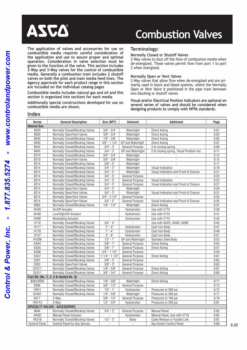
Combustion Valves4The application of valves and accessories for use oncombustible media requires careful consideration ofthe application and use to assure proper and optimaloperation. Consideration in valve selection must begiven to the function of the valve. This section includes2-Way and 3-Way valves for the control of combustiblemedia. Generally a combustion train includes 2 shutoffvalves on both the pilot and main media feed lines. TheAgency approvals for each product range in this sectionare included on the individual catalog pagesCombustible media includes natural gas and oil and thissection is organized into sections for each mediaAdditionally special constructions developed for use oncombustible media are shown.
Terminology:Normally Closed or Shutoff Valves 2-Way valves to shut off the flow of combustion media whende-energized. These valves permit flow from port 1 to port2 when energized.Normally Open or Vent Valves2-Way valves that allow flow when de-energized and are pri-marily used in block and bleed systems, where the NormallyOpen or Vent Valve is positioned in the pipe train betweentwo blocking or shutoff valves.Visual and/or Electrical Position Indicators are optional onseveral series of valves and should be considered whendesigning products to comply with NFPA standards.
Series General Description Size (NPT) Solenoid Additional Page Natural Gas
8030 Normally Closed/Blocking Valves 3/8" 3/4" Watertight Direct Acting 8.01
8030 Normally Open/Vent Valves 3/8" 3/4" Watertight Direct Acting 8.03
8040 Normally Closed/Blocking Valves 1/8" 3/8" Watertight Direct Acting 8.05
8040 Normally Closed/Blocking Valves 3/8" 1 1/4" GP and Watertight Direct Acting 8.07
8042 Normally Closed/Blocking Valves 3/4" 3" General Purpose 5 lb closing spring 8.09
8043 Normally Closed/Blocking Valves 3/4" 3" GP and Watertight 5 lb closing spring, Visual Position Ind. 8.11
8210 Normally Closed/Blocking Valves 3/8" 3/4" Watertight 8.13
8210 Normally Open/Vent Valves 3/8" 3/4" Watertight 8.15
8214 Normally Closed/Blocking Valves 3/8" 2" Watertight 8.17
8214 Normally Closed/Blocking Valves 3/4" 2" Watertight Visual Indication 8.19
8214 Normally Closed/Blocking Valves 3/4" 2" Watertight Visual Indication and Proof of Closure 8.21
8214 Normally Closed/Blocking Valves 3/4" 3" General Purpose 8.23
8214 Normally Closed/Blocking Valves 3/4" 3" General Purpose Visual Indication 8.25
8214 Normally Closed/Blocking Valves 3/4" 3" General Purpose Visual Indication and Proof of Closure 8.27
8214 Normally Open/Vent Valves 3/4" 2" Watertight 8.29
8214 Normally Open/Vent Valves 3/4" 2" Watertight Visual Indication and Proof of Closure 8.31
8214 Normally Open/Vent Valves 3/4" 2 1/2" General Purpose 8.33
8214 Normally Open/Vent Valves 3/4" 2" General Purpose Visual Indication and Proof of Closure 8.35
8262 Normally Closed/Blocking Valves 1/8" 1/4" Watertight Direct Acting 8.37
AH2D On/Off Actuator Hydramotor Use with V710 8.39
AH4D Low/High/Off Actuator Hydramotor Use with V710 8.41
AH8D Modulating Actuator Hydramotor Use with V710 8.43
V710 Normally Closed/Blocking Valves 3/4" 4" Use with AH2D, AH4D, AH8D 8.45
H117 Normally Closed/Blocking Valves 2" 4" Hydramotor Cast Iron Body 8.47
H118 Normally Closed/Blocking Valves 1" 4" Hydramotor Cast Iron Body 8.49
H137 Normally Closed/Blocking Valves 2" 6" Hydramotor Cast Iron Body 8.51
HV266 Normally Closed/Blocking Valves 1/2" 1" GP and Watertight Stainless Steel Body 8.53
K3A4 Normally Closed/Blocking Valves 3/8" 1" General Purpose Direct Acting 8.55
K3A5 Normally Closed/Blocking Valves 3/8" 1" General Purpose Direct Acting 8.57
K3A6 Normally Closed/Blocking Valves 3/4" 1 1/2" General Purpose 8.59
K3A7 Normally Closed/Blocking Valves 1 1/4" 1 1/2" General Purpose Direct Acting 8.61
S261 Normally Closed/Blocking Valves 3/8" 3" General Purpose 8.63
S262 Normally Open/Vent Valves 3/8" 3" General Purpose 8.65
SV311 Normally Closed/Blocking Valves 1/8" 3/8" General Purpose Direct Acting 8.67
SV311 Normally Closed/Blocking Valves 3/8" 3/4" General Purpose Direct Acting 8.69
Fuel OIL (No. 2, 4, 5 & Heated No. 6)8262/8263 Normally Closed/Blocking Valves 1/8" 3/8" Watertight Direct Acting 8.71
8266 Normally Closed/Blocking Valves 3/8" 1/2" General Purpose 8.73
HOV1 Normally Closed/Blocking Valves 1/2" 1" Hydramotor Pressures to 300 psi 8.75
SV401 Normally Closed/Blocking Valves 1/4" 3/8" Watertight Pressures to 300 psi 8.77
8377 3Way 3/8" 1/2" General Purpose Pressures to 100 psi 8.79
HOV13 3Way 1/2" 3/4" Hydramotor Pressures to 300 psi 8.81
SPECIALTY VALVES - ACCESSORIES8044 Normally Closed/Blocking Valves 3/4" 3" General Purpose Manual Reset 8.83
AH2D Manual Reset Actuator Hydramotor Manual Reset, Use with V710 8.85
HV216 Normally Closed/Blocking Valves 1/2" 3" None Cable Release or Fusible Link 8.87
Control Panel Control Panel for Gas Service Key Switch Control Panel 8.89
Index
8.00
Co
ntr
ol
& P
ow
er,
In
c.
-
1.8
77.8
35.5
274
-
ww
w.c
on
tro
lan
dp
ow
er.
co
m
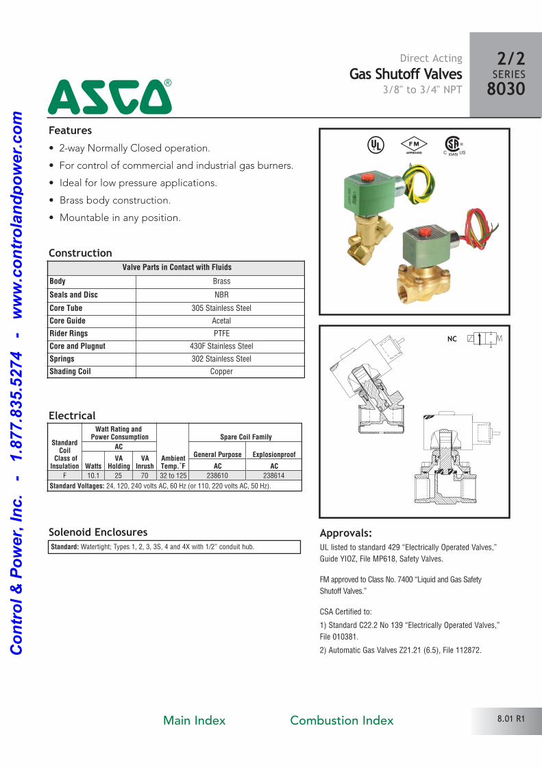
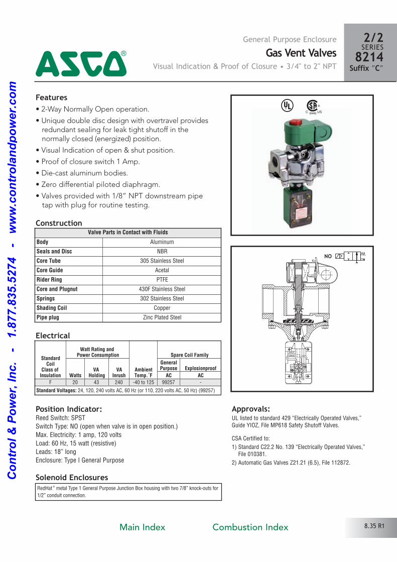
Features• 2way Normally Closed operation.
• For control of commercial and industrial gas burners.
• Ideal for low pressure applications.
• Brass body construction.
• Mountable in any position.
Solenoid Enclosures
Construction
Standard: Watertight; Types 1, 2, 3, 3S, 4 and 4X with 1/2” conduit hub.
Electrical
^ #
Approvals:UL listed to standard 429 “Electrically Operated Valves,”
Guide YIOZ, File MP618, Safety Valves.
FM approved to Class No. 7400 “Liquid and Gas Safety
Shutoff Valves.”
CSA Certified to:
1) Standard C22.2 No 139 “Electrically Operated Valves,”
File 010381.
2) Automatic Gas Valves Z21.21 (6.5), File 112872.
Valve Parts in Contact with Fluids
Body Brass
Seals and Disc NBR
Core Tube 305 Stainless Steel
Core Guide Acetal
Rider Rings PTFE
Core and Plugnut 430F Stainless Steel
Springs 302 Stainless Steel
Shading Coil Copper
NC
Direct ActingGas Shutoff Valves
3/8" to 3/4" NPT4
2/2SERIES8030
StandardCoil
Class ofInsulation
Watt Rating and Power Consumption
AmbientTemp.˚F
Spare Coil Family
ACGeneral Purpose Explosionproof
WattsVA
HoldingVA
Inrush AC ACF 10.1 25 70 32 to 125 238610 238614
Standard Voltages: 24, 120, 240 volts AC, 60 Hz (or 110, 220 volts AC, 50 Hz).
8.01 R1Main Index Combustion Index
Co
ntr
ol
& P
ow
er,
In
c.
-
1.8
77.8
35.5
274
-
ww
w.c
on
tro
lan
dp
ow
er.
co
m
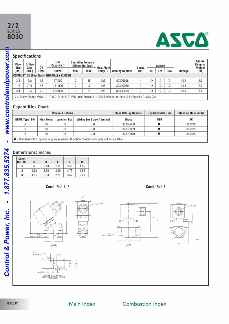
Solenoid Options Base Catalog Number Resilient Materials Standard Rebuild Kit
NEMA Type 3-9 High Temp. Junction Box Wiring Box Screw Terminal Brass NBR AC
EF HT JB JKF 8030G068 � 306628
EF HT JB JKF 8030G069 � 306629
EF HT JB JKF 8030G079 � 306630
PipeSize(ins.)
OrificeSize(ins.)
CVFlow
GasCapacity �
Operating PressureDifferential (psi)
Max. FluidTemp.˚F Catalog Number
Const.Ref.
Agnecy
Wattage
Approx.ShippingWeight(lbs)Btu/hr. Min. Max. UL FM CSA
COMBUSTION (Fuel Gas)- NORMALLY CLOSED
3/8 3/8 1.8 97,000 0 15 125 8030G068 1 � � � 10.1 2.3
1/2 7/16 2.8 151,000 0 8 125 8030G069 2 � � � 10.1 2.7
3/4 3/4 5.0 269,000 0 2 125 8030G079 3 � � � 10.1 3.4
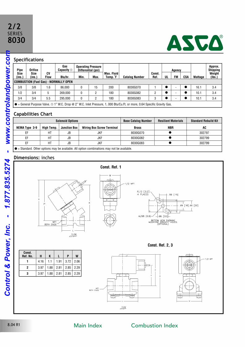
Specifications
Dimensions: inches
Const. Ref. 1, 2
� = Safety Shutoff Valve. � 1” W.C. Drop @ 2” W.C. Inlet Pressure, 1, 000 Btu/cu.ft. or more, 0.64 Specific Gravity Gas.
Const. Ref. 3
Const.Ref. No. H K L P W
1 4 3.14 1.91 3.55 1.95
2 4.32 3.39 2.28 3.77 1.95
3 4.21 2.54 2.81 3.52 2.28
2/2SERIES8030
4
Capabilities Chart
� = Standard. Other options may be available. All option combinations may not be available.
8.02 R1 Main Index Combustion Index
Co
ntr
ol
& P
ow
er,
In
c.
-
1.8
77.8
35.5
274
-
ww
w.c
on
tro
lan
dp
ow
er.
co
m
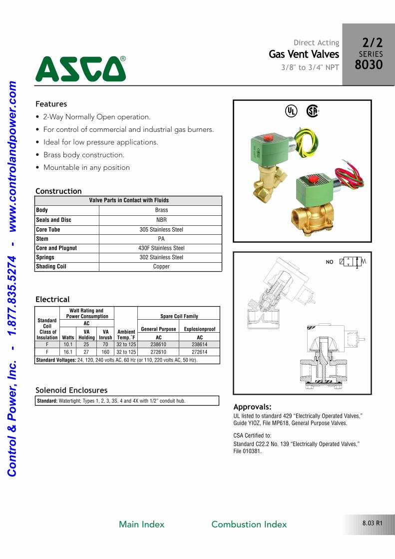
Features• 2Way Normally Open operation.
• For control of commercial and industrial gas burners.
• Ideal for low pressure applications.
• Brass body construction.
• Mountable in any position
Solenoid Enclosures
Construction
Standard: Watertight; Types 1, 2, 3, 3S, 4 and 4X with 1/2” conduit hub.
Electrical
^ %
Approvals:UL listed to standard 429 “Electrically Operated Valves,”Guide YIOZ, File MP618, General Purpose Valves.
CSA Certified to:
Standard C22.2 No. 139 “Electrically Operated Valves,” File 010381.
Valve Parts in Contact with Fluids
Body Brass
Seals and Disc NBR
Core Tube 305 Stainless Steel
Stem PA
Core and Plugnut 430F Stainless Steel
Springs 302 Stainless Steel
Shading Coil CopperNO
4
2/2SERIES8030
Direct ActingGas Vent Valves
3/8" to 3/4" NPT
StandardCoil
Class ofInsulation
Watt Rating and Power Consumption
AmbientTemp.˚F
Spare Coil Family
ACGeneral Purpose Explosionproof
WattsVA
HoldingVA
Inrush AC ACF 10.1 25 70 32 to 125 238610 238614
F 16.1 27 160 32 to 125 272610 272614
Standard Voltages: 24, 120, 240 volts AC, 60 Hz (or 110, 220 volts AC, 50 Hz).
8.03 R1Main Index Combustion Index
Co
ntr
ol
& P
ow
er,
In
c.
-
1.8
77.8
35.5
274
-
ww
w.c
on
tro
lan
dp
ow
er.
co
m
PipeSize(ins.)
OrificeSize(ins.)
CVFlow
GasCapacity �
Operating PressureDifferential (psi)
Max. FluidTemp.˚F Catalog Number
Const.Ref.
Agency
Wattage
Approx.ShippingWeight(lbs.)Btu/hr. Min. Max. UL FM CSA
COMBUSTION (Fuel Gas) - NORMALLY OPEN
3/8 3/8 1.6 86,000 0 15 200 8030G070 1 � � 16.1 3.4
1/2 3/4 5 269,000 0 2 180 8030G082 2 � � 10.1 3.4
3/4 3/4 5.5 295,000 0 2 180 8030G083 3 � � 10.1 3.4
Specifications
Dimensions: inchesConst. Ref. 1
� = General Purpose Valve. � 1” W.C. Drop @ 2” W.C. Inlet Pressure, 1, 000 Btu/Cu.Ft. or more, 0.64 Specific Gravity Gas.
Const. Ref. 2, 3
Const.Ref. No. H K L P W
1 4.16 1.1 1.91 3.72 2.06
2 3.97 1.88 2.81 2.85 2.29
3 3.97 1.88 2.81 2.85 2.29
4
2/2SERIES8030
8.04 R1
Solenoid Options Base Catalog Number Resilient Materials Standard Rebuild Kit
NEMA Type 3-9 High Temp. Junction Box Wiring Box Screw Terminal Brass NBR AC
EF HT JB JKF 8030G070 � 302797
EF HT JB JKF 8030G082 � 302799
EF HT JB JKF 8030G083 � 302799
Capabilities Chart
� = Standard. Other options may be available. All option combinations may not be available.
Main Index Combustion Index
Co
ntr
ol
& P
ow
er,
In
c.
-
1.8
77.8
35.5
274
-
ww
w.c
on
tro
lan
dp
ow
er.
co
m

Features• 2Way Normally Closed operation.
• For gas pilot control of commercial and industrial
gas burners.
• Direct lift with resilient soft seating for tight shutoff.
• Valves provided with 1/8” NPT downstream pipe tap
with plug for routine testing.
• Mountable in any position.
Solenoid Enclosures
Construction
Standard: Watertight; Types 1, 2, 3, 3S, 4, and 4X with 1/2” conduit hub.
Electrical
Approvals:UL listed to standard 429 “Electrically Operated Valves,”Guide YIOZ, File MP618 Safety Valves”.
FM Approved to Class 7400 “Liquid and Gas Safety ShutoffValves.”
CSA Certified to:
1) Standard C22.2 No. 139 “Electrically Operated Valves,” File 010381.
2) Automatic Gas Valves Z21.21 (6.5), File 112872.
3) Automatic Gas Safety Shutoff Valves C/I (3.9), File 112872.
^ #
Valve Parts in Contact with Fluids
Body Aluminum
Seals and Disc NBR
Core Tube 305 Stainless Steel
Core and Plugnut 430F Stainless Steel
Springs 177 PH
Shading Coil Copper
Pipe Plug Zinc Plated Steel
NC
Direct ActingPilot Gas Shutoff Valves
1/8" to 3/8" NPT
2/2SERIES8040
4
StandardCoil
Class ofInsulation
Watt Rating and Power Consumption
AmbientTemp.˚F
Spare Coil Family
ACGeneral Purpose Explosionproof
WattsVA
HoldingVA
Inrush AC ACF 6.1 16 40 40 to 125 238210 238214
Standard Voltages: 24, 120, 240 volts AC, 60 Hz (or 110, 220 volts AC, 50 Hz).
8.05 R1Main Index Combustion Index
Co
ntr
ol
& P
ow
er,
In
c.
-
1.8
77.8
35.5
274
-
ww
w.c
on
tro
lan
dp
ow
er.
co
m
PipeSize(ins.)
OrificeSize(ins.)
CVFlow
GasCapacity �
Operating PressureDifferential (psi) Max. Fluid
Temp.˚F Catalog NumberConst.Ref.
Agency Wattage
Approx.ShippingWeight(lbs)Btu/hr. Min. Max. UL FM CSA
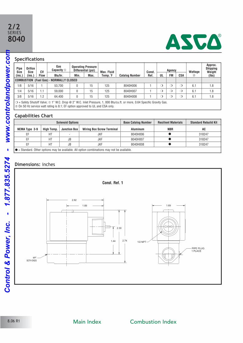
COMBUSTION (Fuel Gas) - NORMALLY CLOSED
1/8 5/16 1 53,700 0 15 125 8040H006 1 � � � 6.1 1.8
1/4 5/16 1.1 59,000 0 15 125 8040H007 1 � � � 6.1 1.8
3/8 5/16 1.2 64,400 0 15 125 8040H008 1 � � � 6.1 1.8
Specifications
Dimensions: inches
Const. Ref. 1
1/2 NPT
1.69
BOTH ENDSNPT
2.92
1.89
2.30
1.44 2.74
PIPE PLUG1 PLACE
2/2SERIES8040
4
� = Safety Shutoff Valve; � 1” W.C. Drop @ 2” W.C. Inlet Pressure, 1, 000 Btu/cu.ft. or more, 0.64 Specific Gravity Gas. On 50 Hz service watt rating is 8.1; EF option approved to UL and CSA only.
Capabilities ChartSolenoid Options Base Catalog Number Resilient Materials Standard Rebuild Kit
NEMA Type 3-9 High Temp. Junction Box Wiring Box Screw Terminal Aluminum NBR AC
EF HT JKF 8040H006 � 318247
EF HT JB JKF 8040H007 � 318247
EF HT JB JKF 8040H008 � 318247
8.06 R1
� = Standard. Other options may be available. All option combinations may not be available.
Main Index Combustion Index
Co
ntr
ol
& P
ow
er,
In
c.
-
1.8
77.8
35.5
274
-
ww
w.c
on
tro
lan
dp
ow
er.
co
m
Features• 2Way Normally Closed operation.
• For gas pilot or main control of commercial and
industrial gas burners.
• Valves provided with 1/8” NPT downstream pipe tap
with plug for routine testing.
• Mountable in any position.
Solenoid Enclosures
Construction
Valves with the letter “G” in their catalog numbers, e.g. 8040G21, have RedHat ® II
molded epoxy Types 1, 2, 3, 3S, 4, and 4X combinations General Purpose and
Watertight solenoid enclosures with 1/2” conduit hub as standard.
Valves with the letter “C” in their catalog numbers, e.g. 8040C4, have RedHat ® metal
Type 1 General Purpose enclosures with 7/8” hole for 1/2” conduit connection.
Electrical
^ #
Approvals:UL listed to standard 429 “Electrically Operated Valves,” Guide YIOZ, File MP618 Safety Valves.
FM Approved to Class 7400 “Liquid and Gas Safety ShutoffValves” (3/8“ thru 3/4” only).
CSA Certified to:
1) Standard C22.2 No. 139 “Electrically Operated Valves,” File 010381.
2) Automatic Gas Valves Z21.21 (6.5), File 112872.
3) Automatic Gas Safety Shutoff Valves C/I (3.9), File 112872.
Valve Parts in Contact with Fluids
Body Aluminum
Seals and Disc NBR
Core Tube 305 Stainless Steel
Core Guide Acetal
Rider Ring PTFE
Core and Plugnut 430F Stainless Steel
Springs 302 Stainless Steel
Shading Coil Copper
Pipe Plug ZincPlated Steel
NC
Direct ActingGas Shutoff Valves
3/8" to 1 1/4" NPT
2/2SERIES8040
4
StandardCoil
Class ofInsulation
Watt Rating and Power Consumption
AmbientTemp.˚F
Spare Coil Family
ACGeneral Purpose Explosionproof
WattsVA
HoldingVA
Inrush AC ACF 10.1 25 70 40 to 125 238610 238614
F 15.4 27 160 40 to 125 099257
Standard Voltages: 24, 120, 240 volts AC, 60 Hz (or 110, 220 volts AC, 50 Hz).
8.07 R1Main Index Combustion Index
Co
ntr
ol
& P
ow
er,
In
c.
-
1.8
77.8
35.5
274
-
ww
w.c
on
tro
lan
dp
ow
er.
co
m
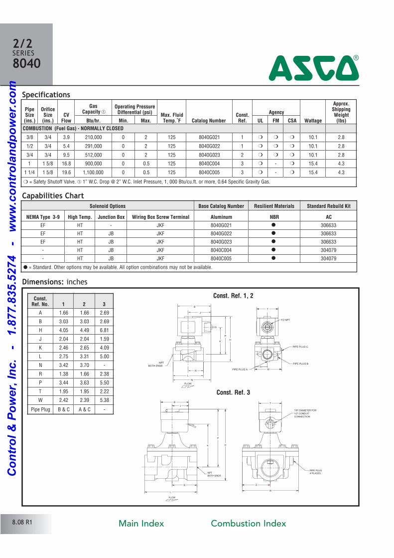
Specifications
Dimensions: inchesConst. Ref. 1, 2
PipeSize(ins.)
OrificeSize(ins.)
CVFlow
GasCapacity �
Operating PressureDifferential (psi) Max. Fluid
Temp.˚F Catalog NumberConst.Ref.
Agency
Wattage
Approx.ShippingWeight(lbs)Btu/hr. Min. Max. UL FM CSA
COMBUSTION (Fuel Gas) - NORMALLY CLOSED
3/8 3/4 3.9 210,000 0 2 125 8040G021 1 � � � 10.1 2.8
1/2 3/4 5.4 291,000 0 2 125 8040G022 1 � � � 10.1 2.8
3/4 3/4 9.5 512,000 0 2 125 8040G023 2 � � � 10.1 2.8
1 1 5/8 16.8 900,000 0 0.5 125 8040C004 3 � � 15.4 4.3
1 1/4 1 5/8 19.6 1,100,000 0 0.5 125 8040C005 3 � � 15.4 4.3
PIPE PLUG4 PLACES
7/8" DIAMETER FOR1/2" CONDUITCONNECTION
NPTBOTH ENDS
WL
K
P
H
BJ
T
AR
FLOW
Const.Ref. No. 1 2 3
A 1.66 1.66 2.69
B 3.03 3.03 2.69
H 4.05 4.49 6.81
J 2.04 2.04 1.59
K 2.46 2.65 4.09
L 2.75 3.31 5.00
N 3.42 3.70
R 1.38 1.66 2.38
P 3.44 3.63 5.50
T 1.95 1.95 2.22
W 2.42 2.39 5.38
Pipe Plug B & C A & C
1/2 NPT
NPTBOTH ENDS
W
HP
K
L
B
JT
N
R
PIPE PLUG C
PIPE PLUG B
PIPE PLUG A
FLOW
A
2/2SERIES8040
4
Const. Ref. 3
� = Safety Shutoff Valve. � 1” W.C. Drop @ 2” W.C. Inlet Pressure, 1, 000 Btu/cu.ft. or more, 0.64 Specific Gravity Gas.
Capabilities ChartSolenoid Options Base Catalog Number Resilient Materials Standard Rebuild Kit
NEMA Type 3-9 High Temp. Junction Box Wiring Box Screw Terminal Aluminum NBR AC
EF HT JKF 8040G021 � 306633
EF HT JB JKF 8040G022 � 306633
EF HT JB JKF 8040G023 � 306633
HT JB JKF 8040C004 � 304079
HT JB JKF 8040C005 � 304079
8.08 R1
� = Standard. Other options may be available. All option combinations may not be available.
Main Index Combustion Index
Co
ntr
ol
& P
ow
er,
In
c.
-
1.8
77.8
35.5
274
-
ww
w.c
on
tro
lan
dp
ow
er.
co
m
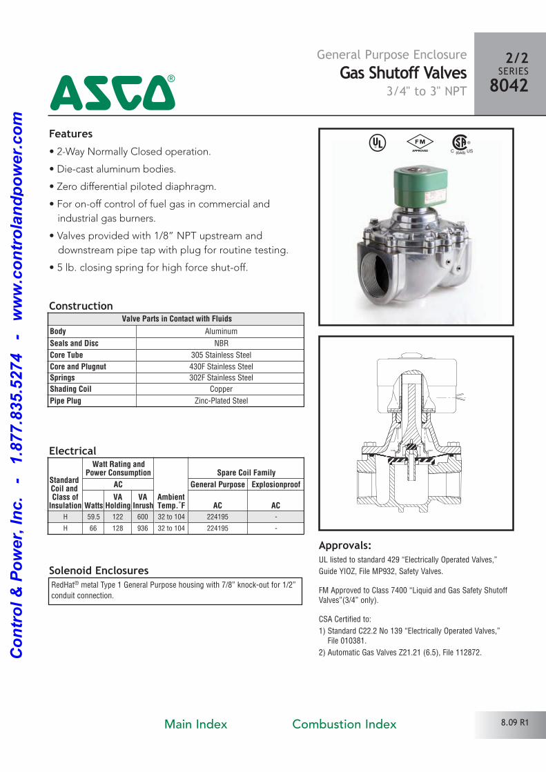
Features• 2Way Normally Closed operation.
• Diecast aluminum bodies.
• Zero differential piloted diaphragm.
• For onoff control of fuel gas in commercial and
industrial gas burners.
• Valves provided with 1/8” NPT upstream and
downstream pipe tap with plug for routine testing.
• 5 lb. closing spring for high force shutoff.
Solenoid Enclosures
Construction
RedHat® metal Type 1 General Purpose housing with 7/8” knockout for 1/2”
conduit connection.
Electrical
Approvals:UL listed to standard 429 “Electrically Operated Valves,”
Guide YIOZ, File MP932, Safety Valves.
FM Approved to Class 7400 “Liquid and Gas Safety ShutoffValves”(3/4” only).
CSA Certified to:
1) Standard C22.2 No 139 “Electrically Operated Valves,” File 010381.
2) Automatic Gas Valves Z21.21 (6.5), File 112872.
General Purpose EnclosureGas Shutoff Valves
3/4" to 3" NPT
2/2SERIES8042
4^ #
8.09 R1
Valve Parts in Contact with Fluids
Body Aluminum
Seals and Disc NBR
Core Tube 305 Stainless Steel
Core and Plugnut 430F Stainless Steel
Springs 302F Stainless Steel
Shading Coil Copper
Pipe Plug ZincPlated Steel
StandardCoil and Class ofInsulation
Watt Rating andPower Consumption
AmbientTemp.˚F
Spare Coil Family
AC General Purpose Explosionproof
WattsVA
HoldingVA
Inrush AC AC
H 59.5 122 600 32 to 104 224195
H 66 128 936 32 to 104 224195
Main Index Combustion Index
Co
ntr
ol
& P
ow
er,
In
c.
-
1.8
77.8
35.5
274
-
ww
w.c
on
tro
lan
dp
ow
er.
co
m
Solenoid Options Resilient Materials Base Catalog Number Standard Rebuild Kit
Rainproof Junction Box NBR Aluminum AC
R JB � 8042D035 304081
R JB � 8042C045 304081
R JB � 8042C055 304081
R JB � 8042C065 304081
R JB � 8042C075 304082
R JB � 8042C085 304083
R JB � 8042C095 304083
Specifications
Dimensions: inches
2/2SERIES8042
4
8.10 R1
Capabilities Chart
� = Standard. Other options may be available. All option combinations my not be available.
PipeSize(ins.)
OrificeSize(ins.)
CvFlow
OperatingPressure
Differential (psi)
Max. FluidTemp.˚F
Standard SolenoidEnclosure
Redhat - Type 1
Gas Capacity1" W.C. Drop @
2" E.C. Inlet Pressure
Approvals
Watt Rating/Class of CoilInsulation
1000 Btu/Cu. Ft. or More 0.64Sp. Gr. Gas
Min. Max.CatalogNumber
Const.Ref. Btu/Hr. UL FM CSA AC
3/4 1 5/8 12.2 0 20 104 8042D035 1 650,000 � � � 59.5/H
1 1 5/8 24 0 20 104 8042C045 2 1,290,000 � � 59.5/H
1 1/4 1 5/8 35 0 20 104 8042C055 2 1,900,000 � � 59.5/H
1 1/2 1 5/8 40 0 20 104 8042C065 2 2,145,000 � � 59.5/H
2 2 3/32 60 0 20 104 8042C075 3 3,241,000 � � 59.5/H
2 1/2 3 120 0 5 104 8042C085 4 6,467,500 � � 66/H
3 3 130 0 5 104 8042C095 4 7,002,500 � � 66/H
� = Safety Shutoff Valve; � 1” W.C. Drop @ 2” W.C. Inlet Pressure, 1, 000 Btu/cu.ft. or more, 0.64 Specific Gravity Gas.
B
F
E
C
A
Ø.875 HOLE FOR 1/2 CONDUIT
CONNECTION
2.16
2.12
3.81
3.31
G
Must be mounted with solenoid vertical and upright.
Const.Ref. A B C E F G
1 2.62 5 7.66 6.34 4.19 5.38
2 2.62 5 7.66 6.39 4.25 5.38
3 3.28 6.09 8.36 6.86 4.72 6.32
4 3.89 7.8 10.22 7.89 5.75 7.99
Main Index Combustion Index
Co
ntr
ol
& P
ow
er,
In
c.
-
1.8
77.8
35.5
274
-
ww
w.c
on
tro
lan
dp
ow
er.
co
m
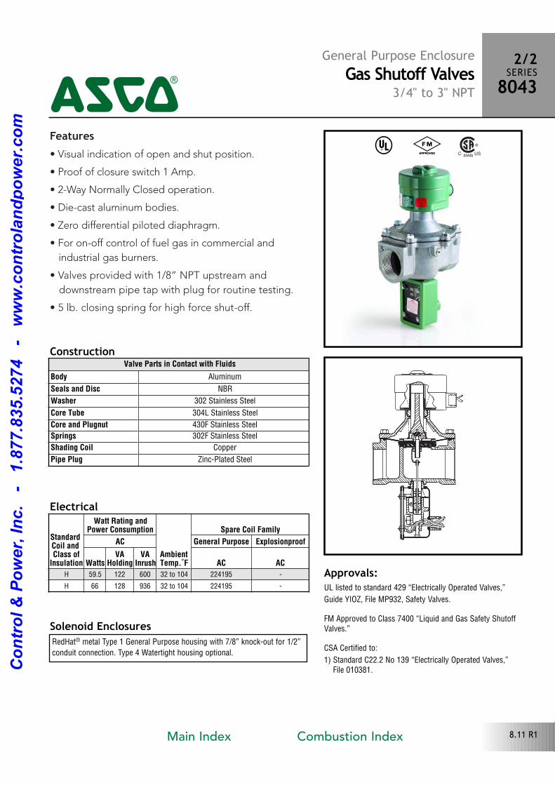
Features• Visual indication of open and shut position.
• Proof of closure switch 1 Amp.
• 2Way Normally Closed operation.
• Diecast aluminum bodies.
• Zero differential piloted diaphragm.
• For onoff control of fuel gas in commercial and
industrial gas burners.
• Valves provided with 1/8” NPT upstream and
downstream pipe tap with plug for routine testing.
• 5 lb. closing spring for high force shutoff.
Solenoid Enclosures
Construction
RedHat® metal Type 1 General Purpose housing with 7/8” knockout for 1/2”
conduit connection. Type 4 Watertight housing optional.
Electrical
Approvals:UL listed to standard 429 “Electrically Operated Valves,”
Guide YIOZ, File MP932, Safety Valves.
FM Approved to Class 7400 “Liquid and Gas Safety ShutoffValves.”
CSA Certified to:
1) Standard C22.2 No 139 “Electrically Operated Valves,” File 010381.
General Purpose EnclosureGas Shutoff Valves
3/4" to 3" NPT
2/2SERIES8043
4^ #
8.11 R1
Valve Parts in Contact with Fluids
Body Aluminum
Seals and Disc NBR
Washer 302 Stainless Steel
Core Tube 304L Stainless Steel
Core and Plugnut 430F Stainless Steel
Springs 302F Stainless Steel
Shading Coil Copper
Pipe Plug ZincPlated Steel
StandardCoil and Class ofInsulation
Watt Rating andPower Consumption
AmbientTemp.˚F
Spare Coil Family
AC General Purpose Explosionproof
WattsVA
HoldingVA
Inrush AC AC
H 59.5 122 600 32 to 104 224195
H 66 128 936 32 to 104 224195
Main Index Combustion Index
Co
ntr
ol
& P
ow
er,
In
c.
-
1.8
77.8
35.5
274
-
ww
w.c
on
tro
lan
dp
ow
er.
co
m
Solenoid Options Resilient MaterialsBase Catalog Number
Type 1Standard Rebuild Kit
Type 1Base Catalog Number
Type 4Standard Rebuild Kit
Type 4
Rainproof Junction Box NBR Aluminum AC Aluminum AC
R JB � 8043B037 304084 8043B038 206142
R JB � 8043A047 304085 8043A048 206143
R JB � 8043A057 304085 8043A058 206143
R JB � 8043A067 304085 8043A068 206143
R JB � 8043A077 304086 8043A078 206144
R JB � 8043A087 310835 8043A088 310836
R JB � 8043A097 310835 8043A098 310836
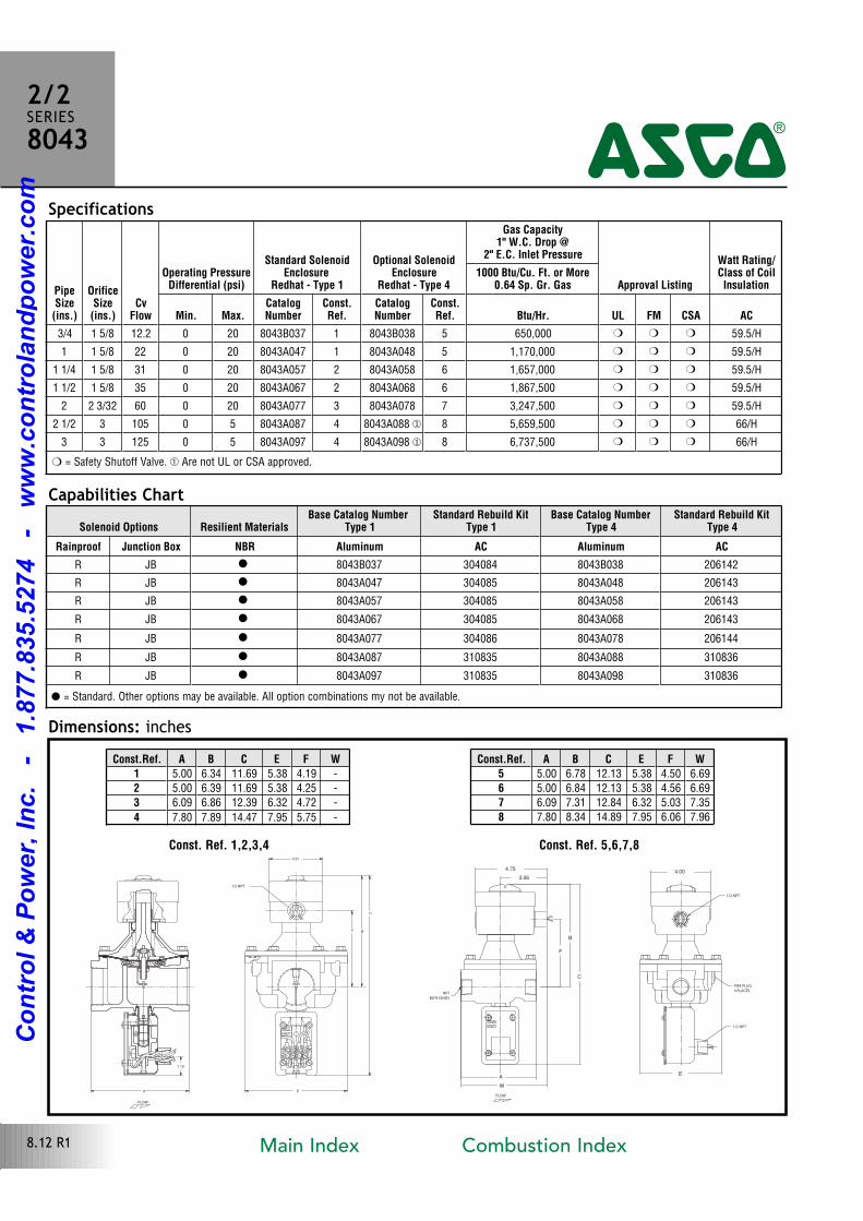
Specifications
Dimensions: inches
2/2SERIES8043
4
8.12 R1
PipeSize(ins.)
OrificeSize(ins.)
CvFlow
Operating PressureDifferential (psi)
Standard SolenoidEnclosure
Redhat - Type 1
Optional SolenoidEnclosure
Redhat - Type 4
Gas Capacity1" W.C. Drop @
2" E.C. Inlet Pressure
Approval Listing
Watt Rating/Class of CoilInsulation
1000 Btu/Cu. Ft. or More0.64 Sp. Gr. Gas
Min. Max.CatalogNumber
Const.Ref.
CatalogNumber
Const.Ref. Btu/Hr. UL FM CSA AC
3/4 1 5/8 12.2 0 20 8043B037 1 8043B038 5 650,000 � � � 59.5/H
1 1 5/8 22 0 20 8043A047 1 8043A048 5 1,170,000 � � � 59.5/H
1 1/4 1 5/8 31 0 20 8043A057 2 8043A058 6 1,657,000 � � � 59.5/H
1 1/2 1 5/8 35 0 20 8043A067 2 8043A068 6 1,867,500 � � � 59.5/H
2 2 3/32 60 0 20 8043A077 3 8043A078 7 3,247,500 � � � 59.5/H
2 1/2 3 105 0 5 8043A087 4 8043A088 � 8 5,659,500 � � � 66/H
3 3 125 0 5 8043A097 4 8043A098 � 8 6,737,500 � � � 66/H
� = Safety Shutoff Valve. � Are not UL or CSA approved.
Capabilities Chart
� = Standard. Other options may be available. All option combinations my not be available.
FLOW
1.19
A E
F B
C
3.31
1/2 NPT
OPEN
SHUT
Const. Ref. 1,2,3,4
NPT
BOTH ENDS
PIPE PLUG
4 PLACES
1/2 NPT
1/2 NPT
W
C
B
F
AE
FLOW
OPEN
SHUT
4.004.75
3.06
Const. Ref. 5,6,7,8
Const.Ref. A B C E F W1 5.00 6.34 11.69 5.38 4.19
2 5.00 6.39 11.69 5.38 4.25
3 6.09 6.86 12.39 6.32 4.72
4 7.80 7.89 14.47 7.95 5.75
Const.Ref. A B C E F W5 5.00 6.78 12.13 5.38 4.50 6.69
6 5.00 6.84 12.13 5.38 4.56 6.69
7 6.09 7.31 12.84 6.32 5.03 7.35
8 7.80 8.34 14.89 7.95 6.06 7.96
Main Index Combustion Index
Co
ntr
ol
& P
ow
er,
In
c.
-
1.8
77.8
35.5
274
-
ww
w.c
on
tro
lan
dp
ow
er.
co
m
Features• 2Way Normally Closed operation.
• For control of commercial and industrial gas burners.
• Ideal for high pressure applications.
• Brass body construction.
• Mountable in any position.
Solenoid Enclosures
Construction
Standard: Watertight, Types 1, 2, 3, 3S, 4 and 4X with 1/2” conduit hub.
Electrical
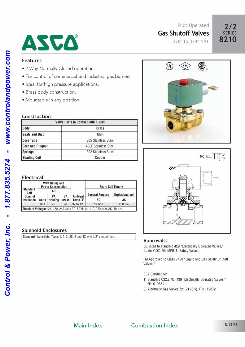
^ #
Approvals:UL listed to standard 429 “Electrically Operated Valves,”Guide YIOZ, File MP618, Safety Valves.
FM Approved to Class 7400 “Liquid and Gas Safety ShutoffValves.”
CSA Certified to:
1) Standard C22.2 No. 139 “Electrically Operated Valves,” File 010381
2) Automatic Gas Valves Z21.21 (6.5), File 112872.
Valve Parts in Contact with Fluids
Body Brass
Seals and Disc NBR
Core Tube 305 Stainless Steel
Core and Plugnut 430F Stainless Steel
Springs 302 Stainless Steel
Shading Coil Copper
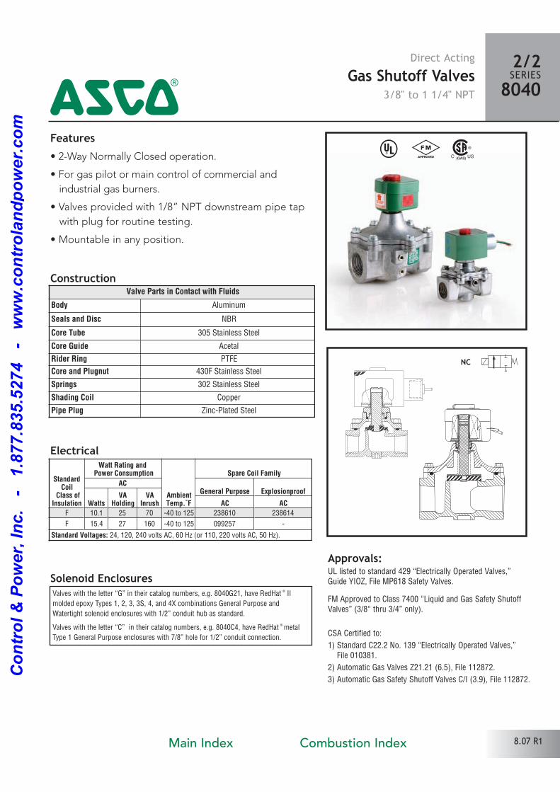
Pilot OperatedGas Shutoff Valves
3/8" to 3/4" NPT
2/2SERIES8210
4
StandardCoil
Class ofInsulation
Watt Rating and Power Consumption
AmbientTemp.˚F
Spare Coil Family
ACGeneral Purpose Explosionproof
WattsVA
HoldingVA
Inrush AC ACF 10.1 25 70 32 to 125 238610 238614
Standard Voltages: 24, 120, 240 volts AC, 60 Hz (or 110, 220 volts AC, 50 Hz).
8.13 R1Main Index Combustion Index
Co
ntr
ol
& P
ow
er,
In
c.
-
1.8
77.8
35.5
274
-
ww
w.c
on
tro
lan
dp
ow
er.
co
m
Specifications
Dimensions: inches
Const. Ref. 1, 2
FLOW
1/2 NPT
NPTBOTHENDS
L
K
PH
W
BJ T
N
A
PipeSize(ins.)
OrificeSize(ins.)
CVFlow
GasCapacity �
Operating PressureDifferential (psi) Max. Fluid
Temp.˚F Catalog NumberConst.Ref.
Agency
Wattage
Approx.ShippingWeight(lbs)Btu/hr. Min. Max. UL FM CSA
COMBUSTION (Fuel Gas) - NORMALLY CLOSED
3/8 5/8 2.8 150,000 0 50 125 8210G074 1 � � � 10.1 3.2
1/2 5/8 3.6 193,000 0 50 125 8210G075 1 � � � 10.1 3.2
3/4 3/4 5.0 295,000 0 50 125 8210G076 2 � � � 10.1 3.4
Const.Ref. No. A B H J K L N P T W
1 1.66 3.03 3.95 2.04 2.42 2.75 3.42 3.39 1.95 2.28
2 1.66 3.03 4.20 2.04 2.58 2.81 3.45 3.55 1.95 2.28
2/2SERIES8210
4
Capabilities Chart� = Safety Shutoff Valve. � 1” W.C. Drop @ 2” W.C. Inlet Pressure, 1, 000 Btu/cu.ft. or more, 0.64 Specific Gravity Gas.
Solenoid Options Base Catalog Number Resilient Materials Standard Rebuild Kit
NEMA Type 3-9 High Temp. Junction Box Wiring Box Screw Terminal Brass NBR AC
EF HT JB JKF 8210G074 � 304076
EF HT JB JKF 8210G075 � 304076
EF HT JB JKF 8210G076 � 304076
8.14 R1
� = Standard. Other options may be available. All option combinations may not be available.
Mountable in any position
Main Index Combustion Index
Co
ntr
ol
& P
ow
er,
In
c.
-
1.8
77.8
35.5
274
-
ww
w.c
on
tro
lan
dp
ow
er.
co
m
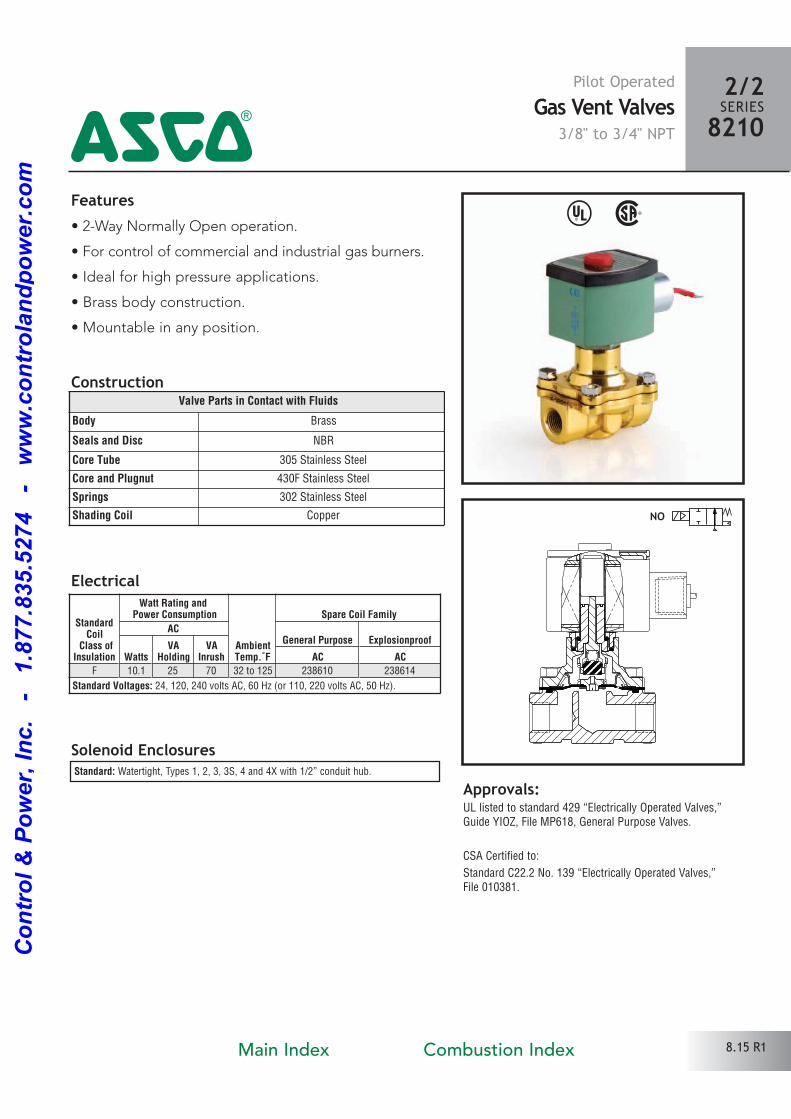
Features• 2Way Normally Open operation.
• For control of commercial and industrial gas burners.
• Ideal for high pressure applications.
• Brass body construction.
• Mountable in any position.
Solenoid Enclosures
Construction
Standard: Watertight, Types 1, 2, 3, 3S, 4 and 4X with 1/2” conduit hub.
Electrical
Approvals:UL listed to standard 429 “Electrically Operated Valves,”Guide YIOZ, File MP618, General Purpose Valves.
CSA Certified to:
Standard C22.2 No. 139 “Electrically Operated Valves,” File 010381.
Valve Parts in Contact with Fluids
Body Brass
Seals and Disc NBR
Core Tube 305 Stainless Steel
Core and Plugnut 430F Stainless Steel
Springs 302 Stainless Steel
Shading Coil Copper NO
2/2SERIES82104
Pilot OperatedGas Vent Valves
3/8" to 3/4" NPT
^ %
StandardCoil
Class ofInsulation
Watt Rating and Power Consumption
AmbientTemp.˚F
Spare Coil Family
ACGeneral Purpose Explosionproof
WattsVA
HoldingVA
Inrush AC ACF 10.1 25 70 32 to 125 238610 238614
Standard Voltages: 24, 120, 240 volts AC, 60 Hz (or 110, 220 volts AC, 50 Hz).
8.15 R1Main Index Combustion Index
Co
ntr
ol
& P
ow
er,
In
c.
-
1.8
77.8
35.5
274
-
ww
w.c
on
tro
lan
dp
ow
er.
co
m
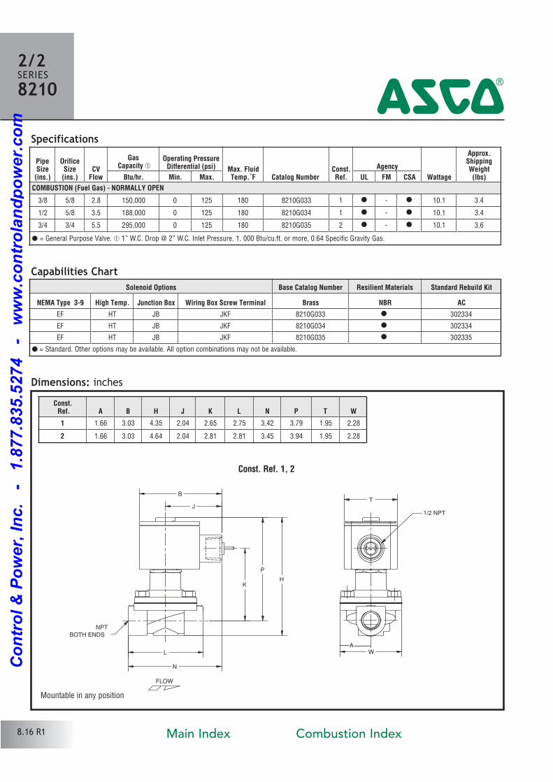
PipeSize(ins.)
OrificeSize(ins.)
CVFlow
GasCapacity �
Operating PressureDifferential (psi) Max. Fluid
Temp.˚F Catalog NumberConst.Ref.
Agency
Wattage
Approx.ShippingWeight(lbs)Btu/hr. Min. Max. UL FM CSA
COMBUSTION (Fuel Gas) - NORMALLY OPEN
3/8 5/8 2.8 150,000 0 125 180 8210G033 1 � � 10.1 3.4
1/2 5/8 3.5 188,000 0 125 180 8210G034 1 � � 10.1 3.4
3/4 3/4 5.5 295,000 0 125 180 8210G035 2 � � 10.1 3.6
Specifications
Dimensions: inches
Const. Ref. 1, 2
NPT
BOTH ENDS
1/2 NPT
W
K
P
H
L
J
BT
N
FLOW
A
Const. Ref. A B H J K L N P T W
1 1.66 3.03 4.35 2.04 2.65 2.75 3.42 3.79 1.95 2.28
2 1.66 3.03 4.64 2.04 2.81 2.81 3.45 3.94 1.95 2.28
2/2SERIES8210
4
Capabilities Chart
� = General Purpose Valve. � 1” W.C. Drop @ 2” W.C. Inlet Pressure, 1, 000 Btu/cu.ft. or more, 0.64 Specific Gravity Gas.
Solenoid Options Base Catalog Number Resilient Materials Standard Rebuild Kit
NEMA Type 3-9 High Temp. Junction Box Wiring Box Screw Terminal Brass NBR AC
EF HT JB JKF 8210G033 � 302334
EF HT JB JKF 8210G034 � 302334
EF HT JB JKF 8210G035 � 302335
8.16 R1
� = Standard. Other options may be available. All option combinations may not be available.
Mountable in any position
Main Index Combustion Index
Co
ntr
ol
& P
ow
er,
In
c.
-
1.8
77.8
35.5
274
-
ww
w.c
on
tro
lan
dp
ow
er.
co
m
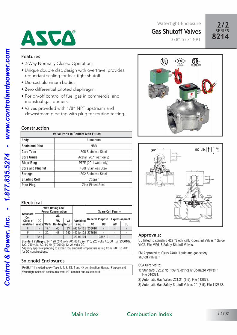
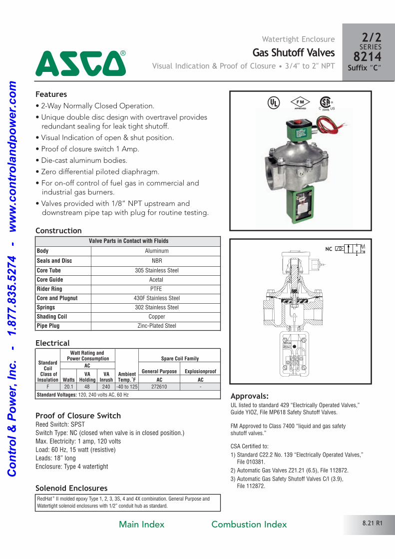
Features• 2Way Normally Closed Operation.
• Unique double disc design with overtravel providesredundant sealing for leak tight shutoff.
• Diecast aluminum bodies.
• Zero differential piloted diaphragm.
• For onoff control of fuel gas in commercial and industrial gas burners.
• Valves provided with 1/8” NPT upstream and downstream pipe tap with plug for routine testing.
Solenoid Enclosures
Construction
Electrical
^ #
Approvals:UL listed to standard 429 “Electrically Operated Valves,” GuideYIOZ, File MP618 Safety Shutoff Valves.
FM Approved to Class 7400 “liquid and gas safety shutoff valves.”
CSA Certified to:
1) Standard C22.2 No. 139 “Electrically Operated Valves,” File 010381.
2) Automatic Gas Valves Z21.21 (6.5), File 112872.
3) Automatic Gas Safety Shutoff Valves C/I (3.9), File 112872.
RedHat ® II molded epoxy Type 1, 2, 3, 3S, 4 and 4X combination. General Purpose and
Watertight solenoid enclosures with 1/2” conduit hub as standard.
Valve Parts in Contact with Fluids
Body Aluminum
Seals and Disc NBR
Core Tube 305 Stainless Steel
Core Guide Acetal (20.1 watt only)
Rider Ring PTFE (20.1 watt only)
Core and Plugnut 430F Stainless Steel
Springs 302 Stainless Steel
Shading Coil Copper
Pipe Plug ZincPlated Steel
NC
Watertight EnclosureGas Shutoff Valves
3/8" to 2" NPT
2/2SERIES82144
8.17 R1
StandardCoil
Class ofInsulation
Watt Rating and Power Consumption
*AmbientTemp.˚F
Spare Coil Family
DCWatts
ACGeneral Purpose Explosionproof
WattsVA
HoldingVA
Inrush AC DC AC DC
F 17.1 40 93 40 to 125 238610
F 20.1 48 240 40 to 125 272610
F 22.6 20 to 104 238710
Standard Voltages: 24, 120, 240 volts AC, 60 Hz (or 110, 220 volts AC, 50 Hz) (238610); 120, 240 volts AC, 60 Hz (272610); 12, 24 volts DC. *Agency approval pending to extend low ambient temperature rating from 20˚F to 40˚F for DC constructions.
Main Index Combustion Index
Co
ntr
ol
& P
ow
er,
In
c.
-
1.8
77.8
35.5
274
-
ww
w.c
on
tro
lan
dp
ow
er.
co
m
Solenoid Options Base Catalog Number Resilient Materials Standard Rebuild Kit
High Temp. Junction Box Aluminum NBR AC DC
HB JB 8214G010 � 316233 316790
HB JB 8214G020 � 316233 316790
HB JB 8214G030 � 316233 316790
HB JB 8214G036 � 322374
HB JB 8214G051 � 322374
HB JB 8214G061 � 322374
HB JB 8214G071 � 322374
HB JB 8214G081 � 322376
PipeSize
(ins.)
OrificeSize
(ins.)CV
Flow
GasCapacity �
Operating PressureDifferential (psi)
Max. FluidTemp.˚F
Catalog NumberConst.Ref.
Agency Wattage
Approx.ShippingWeight(lbs)Btu/hr. Min. Max. AC DC UL FM CSA AC DC
COMBUSTION (Fuel Gas) - NORMALLY CLOSED
3/8 3/4 3.4 183,000 0 5 125 104 8214G010 1 � � � 17.1 22.6 2
1/2 3/4 4.4 238,500 0 5 125 104 8214G020 1 � � � 17.1 22.6 2
3/4 3/4 5.1 247,500 0 5 125 104 8214G030 2 � � � 17.1 22.6 2
3/4 1 5/8 11 580,000 0 5 125 8214G036 3 � � � 20.1 4.3
1 1 5/8 21 1,119,000 0 5 125 8214G051 3 � � � 20.1 4.3
1 1/4 1 5/8 32 1,730,000 0 5 125 8214G061 4 � � � 20.1 4.3
1 1/2 1 5/8 35 1,900,000 0 5 125 8214G071 4 � � � 20.1 4.3
2 2 3/32 60 2,800,000 0 5 125 8214G081 5 � � � 20.1 6.3
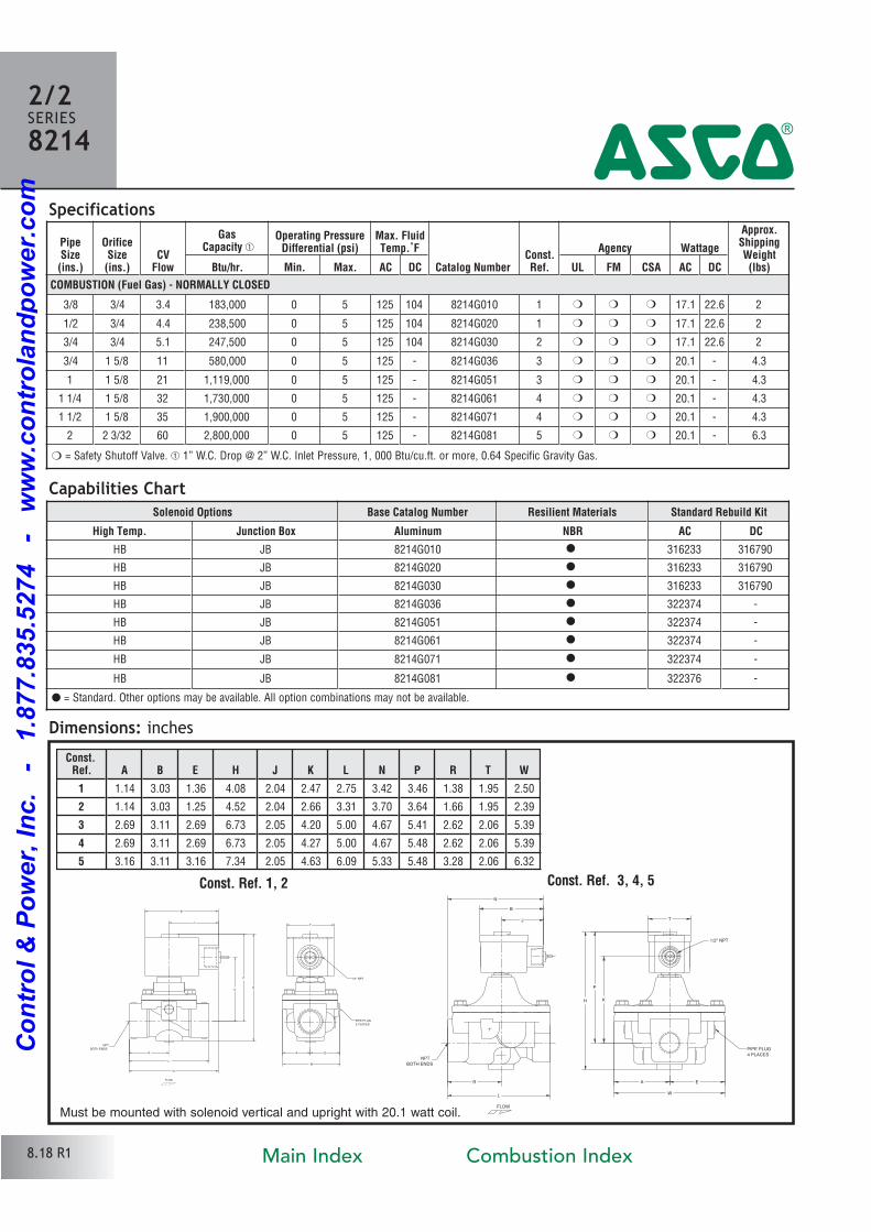
Specifications
Dimensions: inches
Const. Ref. 1, 2 Const. Ref. 3, 4, 5
1/2" NPT
PIPE PLUG
2 PLACES
NPT
BOTH ENDS
T
L
K
P
W
H
B
J
N
R A E
FLOW
PIPE PLUG
4 PLACESNPT
BOTH ENDS
1/2" NPT
T
LW
K
P
H
B
J
R
N
A E
FLOW
2/2SERIES8214
4
Capabilities Chart� = Safety Shutoff Valve. � 1” W.C. Drop @ 2” W.C. Inlet Pressure, 1, 000 Btu/cu.ft. or more, 0.64 Specific Gravity Gas.
Must be mounted with solenoid vertical and upright with 20.1 watt coil.
8.18 R1
� = Standard. Other options may be available. All option combinations may not be available.
Const.Ref. A B E H J K L N P R T W
1 1.14 3.03 1.36 4.08 2.04 2.47 2.75 3.42 3.46 1.38 1.95 2.50
2 1.14 3.03 1.25 4.52 2.04 2.66 3.31 3.70 3.64 1.66 1.95 2.39
3 2.69 3.11 2.69 6.73 2.05 4.20 5.00 4.67 5.41 2.62 2.06 5.39
4 2.69 3.11 2.69 6.73 2.05 4.27 5.00 4.67 5.48 2.62 2.06 5.39
5 3.16 3.11 3.16 7.34 2.05 4.63 6.09 5.33 5.48 3.28 2.06 6.32
Main Index Combustion Index
Co
ntr
ol
& P
ow
er,
In
c.
-
1.8
77.8
35.5
274
-
ww
w.c
on
tro
lan
dp
ow
er.
co
m
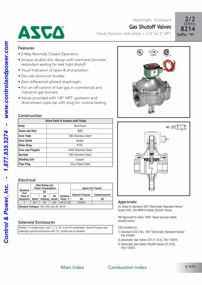
Features• 2Way Normally Closed Operation.
• Unique double disc design with overtravel providesredundant sealing for leak tight shutoff.
• Visual Indication of open & shut position.
• Diecast aluminum bodies.
• Zero differential piloted diaphragm.
• For onoff control of fuel gas in commercial and industrial gas burners.
• Valves provided with 1/8” NPT upstream and downstream pipe tap with plug for routine testing.
Solenoid Enclosures
Construction
Electrical
Approvals:UL listed to standard 429 “Electrically Operated Valves,”Guide YIOZ, File MP618 Safety Shutoff Valves.
FM Approved to Class 7400 “liquid and gas safety shutoff valves”.
CSA Certified to:
1) Standard C22.2 No. 139 “Electrically Operated Valves,” File 010381.
2) Automatic Gas Valves Z21.21 (6.5), File 112872.
3) Automatic Gas Safety Shutoff Valves C/I (3.9), File 112872.
NC
Watertight EnclosureGas Shutoff Valves
Visual Position Indication • 3/4" to 2" NPT
2/2SERIES8214
Suffix ”VI”4
8.19 R1
^ #
RedHat ® II molded epoxy Type 1, 2, 3, 3S, 4 and 4X combination. General Purpose and
watertight solenoid enclosures with 1/2” conduit hub as standard.
Valve Parts in Contact with Fluids
Body Aluminum
Seals and Disc NBR
Core Tube 305 Stainless Steel
Core Guide Acetal
Rider Ring PTFE
Core and Plugnut 430F Stainless Steel
Springs 302 Stainless Steel
Shading Coil Copper
Pipe Plug ZincPlated Steel
StandardCoil
Class ofInsulation
Watt Rating and Power Consumption
AmbientTemp.˚F
Spare Coil Family
ACGeneral Purpose Explosionproof
WattsVA
HoldingVA
Inrush AC ACF 20.1 48 240 40 to 125 272610
Standard Voltages: 120, 240 volts AC, 60 Hz
Main Index Combustion Index
Co
ntr
ol
& P
ow
er,
In
c.
-
1.8
77.8
35.5
274
-
ww
w.c
on
tro
lan
dp
ow
er.
co
m
Specifications
Dimensions: inches
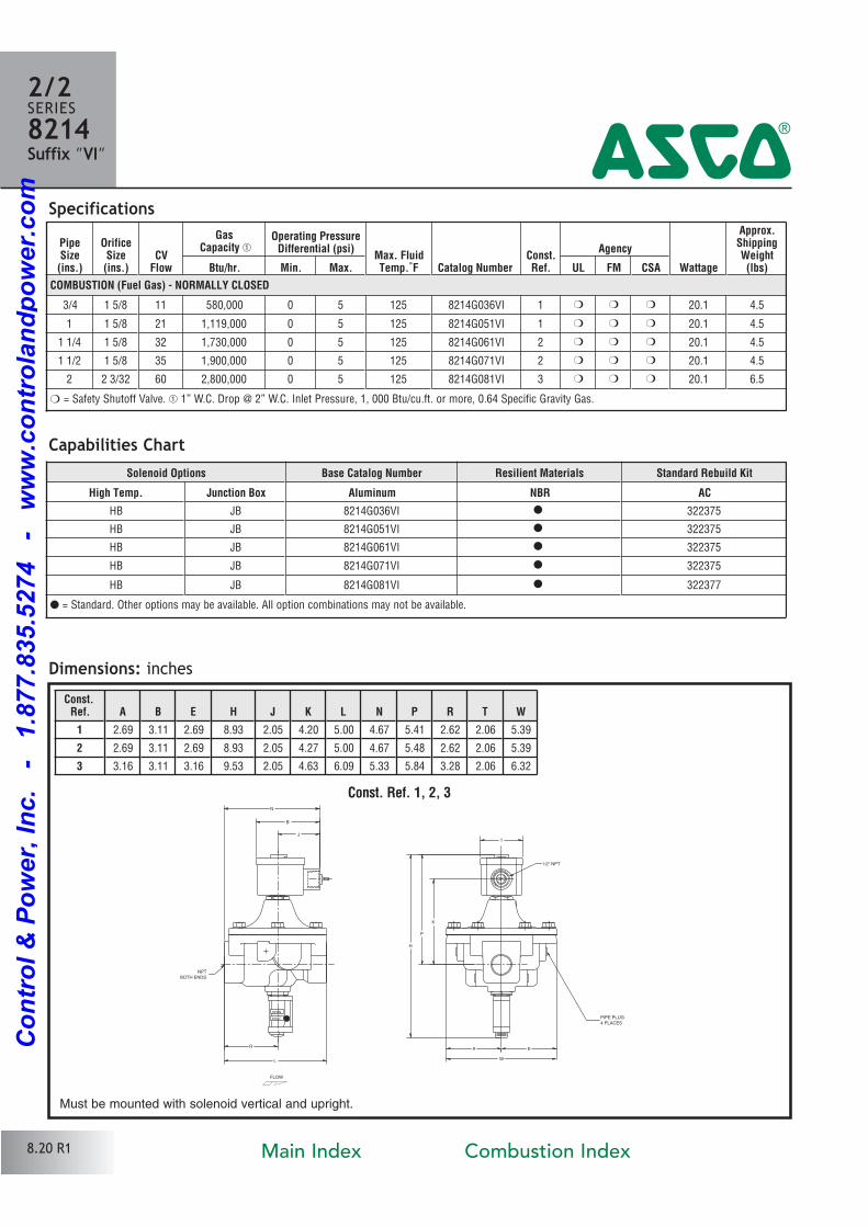
Const. Ref. 1, 2, 3
1/2" NPT
PIPE PLUG
4 PLACES
NPT
BOTH ENDS
W
T
K
P
H
L
B
J
R
N
A
FLOW
SHUT
OPEN
E
2/2SERIES8214Suffix ”VI” 4
Capabilities Chart
Must be mounted with solenoid vertical and upright.
8.20 R1
PipeSize(ins.)
OrificeSize(ins.)
CVFlow
GasCapacity �
Operating PressureDifferential (psi)
Max. FluidTemp.˚F Catalog Number
Const.Ref.
Agency
Wattage
Approx.ShippingWeight(lbs)Btu/hr. Min. Max. UL FM CSA
COMBUSTION (Fuel Gas) - NORMALLY CLOSED
3/4 1 5/8 11 580,000 0 5 125 8214G036VI 1 � � � 20.1 4.5
1 1 5/8 21 1,119,000 0 5 125 8214G051VI 1 � � � 20.1 4.5
1 1/4 1 5/8 32 1,730,000 0 5 125 8214G061VI 2 � � � 20.1 4.5
1 1/2 1 5/8 35 1,900,000 0 5 125 8214G071VI 2 � � � 20.1 4.5
2 2 3/32 60 2,800,000 0 5 125 8214G081VI 3 � � � 20.1 6.5
� = Safety Shutoff Valve. � 1” W.C. Drop @ 2” W.C. Inlet Pressure, 1, 000 Btu/cu.ft. or more, 0.64 Specific Gravity Gas.
Solenoid Options Base Catalog Number Resilient Materials Standard Rebuild Kit
High Temp. Junction Box Aluminum NBR AC
HB JB 8214G036VI � 322375
HB JB 8214G051VI � 322375
HB JB 8214G061VI � 322375
HB JB 8214G071VI � 322375
HB JB 8214G081VI � 322377
� = Standard. Other options may be available. All option combinations may not be available.
Const.Ref. A B E H J K L N P R T W
1 2.69 3.11 2.69 8.93 2.05 4.20 5.00 4.67 5.41 2.62 2.06 5.39
2 2.69 3.11 2.69 8.93 2.05 4.27 5.00 4.67 5.48 2.62 2.06 5.39
3 3.16 3.11 3.16 9.53 2.05 4.63 6.09 5.33 5.84 3.28 2.06 6.32
Main Index Combustion Index
Co
ntr
ol
& P
ow
er,
In
c.
-
1.8
77.8
35.5
274
-
ww
w.c
on
tro
lan
dp
ow
er.
co
m
Features• 2Way Normally Closed Operation.
• Unique double disc design with overtravel providesredundant sealing for leak tight shutoff.
• Visual Indication of open & shut position.
• Proof of closure switch 1 Amp.
• Diecast aluminum bodies.
• Zero differential piloted diaphragm.
• For onoff control of fuel gas in commercial and industrial gas burners.
• Valves provided with 1/8” NPT upstream and downstream pipe tap with plug for routine testing.
Solenoid Enclosures
Construction
Electrical
Approvals:UL listed to standard 429 “Electrically Operated Valves,”Guide YIOZ, File MP618 Safety Shutoff Valves.
FM Approved to Class 7400 “liquid and gas safety shutoff valves.”
CSA Certified to:
1) Standard C22.2 No. 139 “Electrically Operated Valves,” File 010381.
2) Automatic Gas Valves Z21.21 (6.5), File 112872.
3) Automatic Gas Safety Shutoff Valves C/I (3.9), File 112872.
NC
Watertight EnclosureGas Shutoff Valves
Visual Indication & Proof of Closure • 3/4" to 2" NPT
2/2SERIES8214
Suffix ”C”4
8.21 R1
^ #
RedHat ® II molded epoxy Type 1, 2, 3, 3S, 4 and 4X combination. General Purpose and
Watertight solenoid enclosures with 1/2” conduit hub as standard.
Proof of Closure SwitchReed Switch: SPST
Switch Type: NC (closed when valve is in closed position.)
Max. Electricity: 1 amp, 120 volts
Load: 60 Hz, 15 watt (resistive)
Leads: 18” long
Enclosure: Type 4 watertight
Valve Parts in Contact with Fluids
Body Aluminum
Seals and Disc NBR
Core Tube 305 Stainless Steel
Core Guide Acetal
Rider Ring PTFE
Core and Plugnut 430F Stainless Steel
Springs 302 Stainless Steel
Shading Coil Copper
Pipe Plug ZincPlated Steel
StandardCoil
Class ofInsulation
Watt Rating and Power Consumption
AmbientTemp.˚F
Spare Coil Family
ACGeneral Purpose Explosionproof
WattsVA
HoldingVA
Inrush AC ACF 20.1 48 240 40 to 125 272610
Standard Voltages: 120, 240 volts AC, 60 Hz
Main Index Combustion Index
Co
ntr
ol
& P
ow
er,
In
c.
-
1.8
77.8
35.5
274
-
ww
w.c
on
tro
lan
dp
ow
er.
co
m
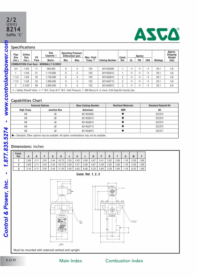
Specifications
Dimensions: inches
Const. Ref. 1, 2, 3
NPT
BOTH
ENDS
PIPE PLUG
4 PLACES
1/2" NPT
H
P
W
U
Y
F
K
T
L
B
J
G
R
N
A
FLOW
2/2SERIES8214Suffix ”C” 4
Capabilities Chart
Must be mounted with solenoid vertical and upright.
8.22 R1
PipeSize(ins.)
OrificeSize(ins.)
CVFlow
GasCapacity �
Operating PressureDifferential (psi)
Max. FluidTemp.˚F Catalog Number
Const.Ref.
Agency
Wattage
Approx.ShippingWeight(lbs)Btu/hr. Min. Max. UL FM CSA
COMBUSTION (Fuel Gas) - NORMALLY CLOSED
3/4 1 5/8 11 580,000 0 5 125 8214G036C 1 � � � 20.1 4.8
1 1 5/8 21 1,119,000 0 5 125 8214G051C 1 � � � 20.1 4.8
1 1/4 1 5/8 32 1,730,000 0 5 125 8214G061C 2 � � � 20.1 4.8
1 1/2 1 5/8 35 1,900,000 0 5 125 8214G071C 2 � � � 20.1 4.8
2 2 3/32 60 2,800,000 0 5 125 8214G081C 3 � � � 20.1 6.8
� = Safety Shutoff Valve. � 1” W.C. Drop @ 2” W.C. Inlet Pressure, 1, 000 Btu/cu.ft. or more, 0.64 Specific Gravity Gas.
Solenoid Options Base Catalog Number Resilient Materials Standard Rebuild Kit
High Temp. Junction Box Aluminum NBR AC
HB JB 8214G036C � 322375
HB JB 8214G051C � 322375
HB JB 8214G061C � 322375
HB JB 8214G071C � 322375
HB JB 8214G081C � 322377
� = Standard. Other options may be available. All option combinations may not be available.
Const.Ref. A B F G H J K L N P R T U W Y
1 2.69 3.11 2.91 2.44 10.72 2.05 4.20 5.00 4.67 5.41 2.62 2.06 1.18 5.39 1.69
2 2.69 3.11 2.91 2.44 10.72 2.05 4.27 5.00 4.67 5.48 2.62 2.06 1.18 5.39 1.69
3 3.16 3.11 2.91 2.44 11.33 2.05 4.63 6.09 5.33 5.84 3.28 2.06 1.18 6.32 1.69
Main Index Combustion Index
Co
ntr
ol
& P
ow
er,
In
c.
-
1.8
77.8
35.5
274
-
ww
w.c
on
tro
lan
dp
ow
er.
co
m

Features• 2Way Normally Closed Operation.
• Unique double disc design with overtravel providesredundant sealing for leak tight shutoff.
• Diecast aluminum bodies.
• Zero differential piloted diaphragm.
• For onoff control of fuel gas in commercial and industrial gas burners.
• Valves provided with 1/8” NPT upstream and downstream pipe tap with plug for routine testing.
Solenoid Enclosures
Construction
Electrical
^ #
Approvals:UL listed to standard 429 “Electrically Operated Valves,” GuideYIOZ, File MP618 Safety Shutoff Valves.
FM Approved “Process Control Valves.”
CSA Certified to:
1) Standard C22.2 No. 139 “Electrically Operated Valves,” File 010381.
2) Automatic Gas Valves Z21.21 (6.5), File 112872.
3) Automatic Gas Safety Shutoff Valves C/I (3.9), File 112872.
RedHat ® metal Type 1 General Purpose Junction Box housing with two 7/8” knockouts for
1/2” conduit connection.
Valve Parts in Contact with Fluids
Body Aluminum
Seals and Disc NBR
Core Tube 305 Stainless Steel
Core Guide Acetal (20 watt only)
Rider Ring PTFE (20 watt only)
Core and Plugnut 430F Stainless Steel
Springs 302 Stainless Steel
Shading Coil Copper
Pipe Plug ZincPlated Steel
NC
General Purpose EnclosureGas Shutoff Valves
3/4" to 3" NPT
2/2SERIES82144
StandardCoil
Class ofInsulation
Watt Rating and Power Consumption
*AmbientTemp.˚F
Spare Coil Family
DCWatts
ACGeneral Purpose Explosionproof
WattsVA
HoldingVA
Inrush AC DC AC DC
F 20 43 240 40 to 125 099257
F 28.2 50 385 40 to 125 206409
B 14.9 20 to 77 062691
Standard Voltages: 24, 120, 240 volts AC, 60 Hz (or 110, 220 volts AC, 50 Hz) 12, 24 volts DC.*Agency approval pending to extend low ambient temperature rating from 20˚F to 40˚F for DC constructions.
8.23 R1Main Index Combustion Index
Co
ntr
ol
& P
ow
er,
In
c.
-
1.8
77.8
35.5
274
-
ww
w.c
on
tro
lan
dp
ow
er.
co
m
Specifications
Dimensions: inches (Shown with optional Junction Box)
Const. Ref. 1, 2, 3 Const. Ref. 4
PipeSize
(ins.)
OrificeSize
(ins.)CV
Flow
GasCapacity �
Operating PressureDifferential (psi)
Max. FluidTemp.˚F
Catalog NumberConst.Ref.
Agency Wattage
Approx.ShippingWeight
(lbs)Btu/hr. Min. Max. AC DC UL FM CSA AC DC
COMBUSTION (Fuel Gas) - NORMALLY CLOSED
3/4 1 5/8 11 580,000 0 5 125 77 8214 035 1 � � 20 14.9 4.3
1 1 5/8 21 1,119,000 0 5 125 77 8214 050 1 � � 20 14.9 4.3
1 1/4 1 5/8 32 1,730,000 0 5 125 77 8214 060 2 � � 20 14.9 4.3
1 1/2 1 5/8 35 1,900,000 0 5 125 77 8214 070 2 � � 20 14.9 4.3
2 2 3/32 60 2,800,000 0 5 125 77 8214 080 3 � � 20 14.9 6.3
2 1/2 3 104 5,765,500 0 5 125 8214 090 4 � � 28.2 13.0
3 3 105 5,796,000 0 5 125 8214 040 4 � � 28.2 14.0
FLOW
A
T
C
R
N
B
J
M
W
L
HK
P
(BOTH SIDES)
1/2" CONDUIT CONNECTION
7/8" DIAMETER KNOCKOUT FOR
BOTH ENDS
NPT
4 PLACES
PIPE PLUG
NPT
BOTH ENDS
PIPE PLUG4 PLACES
7/8" DIAMETER KNOCKOUT FOR
1/2" CONDUIT CONNECTION(BOTH SIDES)
H
P
L W
K
BJ
M
R
T
C
N
A
FLOW
O TU
INSTRUCTION CARD
2/2SERIES8214
4
Const.Ref. A B C H J K L M N P R T W
1 2.69 4.59 1.88 6.78 3.53 4.06 5.00 2.50 6.15 5.46 2.62 2.20 5.39
2 2.69 4.59 1.88 6.78 3.53 4.13 5.00 2.50 6.15 5.53 2.62 2.20 5.39
3 3.16 4.59 1.88 7.39 3.53 4.49 6.09 2.50 6.81 5.89 3.28 2.20 6.32
4 4.13 5.72 1.88 10.20 4.07 5.71 7.80 3.07 7.96 7.87 3.89 3.31 7.95
Solenoid Options Base Catalog Number Resilient Materials Standard Rebuild Kit
Rainproof High Temp. Junction Box Wiring Box Screw Terminal Aluminum NBR AC DC
R HB JB JKP 8214 035 � 316429 316777
R HB JB JKP 8214 050 � 316429 316777
R HB JB JKP 8214 060 � 316429 316777
R HB JB JKP 8214 070 � 316429 316777
R HB JB JKP 8214 080 � 316430 316778
R HT JB JKF 8214 090 � 316828
R HT JB JKF 8214 040 � 316828
Capabilities Chart
� = Safety Shutoff Valve. � 1” W.C. Drop @ 2” W.C. Inlet Pressure, 1, 000 Btu/cu.ft. or more, 0.64 Specific Gravity Gas; FM approved “Process Control Valves”.
Must be mounted with solenoid vertical and upright.
8.24 R1
� = Standard. Other options may be available. All option combinations may not be available.
Main Index Combustion Index
Co
ntr
ol
& P
ow
er,
In
c.
-
1.8
77.8
35.5
274
-
ww
w.c
on
tro
lan
dp
ow
er.
co
m
Features• 2Way Normally Closed Operation.
• Unique double disc design with overtravel providesredundant sealing for leak tight shutoff.
• Visual Indication of open & shut position.
• Diecast aluminum bodies.
• Zero differential piloted diaphragm.
• For onoff control of fuel gas in commercial and industrial gas burners.
• Valves provided with 1/8” NPT upstream and downstream pipe tap with plug for routine testing.
Solenoid Enclosures
Construction
Electrical
^ #
Approvals:UL listed to standard 429 “Electrically Operated Valves,”Guide YIOZ, File MP618 Safety Shutoff Valves.
FM Approved to Class 7400 “liquid and gas safety shutoff valves.”
CSA Certified to:
1) Standard C22.2 No. 139 “Electrically Operated Valves,” File 010381.
2) Automatic Gas Valves Z21.21 (6.5), File 112872.
3) Automatic Gas Safety Shutoff Valves C/I (3.9), File 112872.
RedHat ® metal Type 1 General Purpose Junction Box housing with two 7/8” knockouts for
1/2” conduit connection.
NC
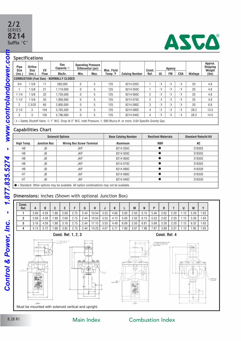
General Purpose EnclosureGas Shutoff Valves
Visual Position Indication • 3/4" to 3" NPT
2/2SERIES8214
Suffix ”VI”4
8.25 R1
Valve Parts in Contact with Fluids
Body Aluminum
Seals and Disc NBR
Core Tube 305 Stainless Steel
Core Guide Acetal (20 watt only)
Rider Ring PTFE (20 watt only)
Core and Plugnut 430F Stainless Steel
Springs 302 Stainless Steel
Shading Coil Copper
Pipe Plug ZincPlated Steel
StandardCoil
Class ofInsulation
Watt Rating and Power Consumption
AmbientTemp.˚F
Spare Coil Family
ACGeneral Purpose Explosionproof
WattsVA
HoldingVA
Inrush AC AC
F 20 43 240 40 to 125 99257
F 28.2 50 385 40 to 125 206409
Standard Voltages: 24, 120, 240 volts AC, 60 Hz (or 110, 220 volts AC, 50 Hz) (99257); 120, 240 volts AC, 60 Hz (or 110, 220 volts AC, 50 Hz) (206409).
Main Index Combustion Index
Co
ntr
ol
& P
ow
er,
In
c.
-
1.8
77.8
35.5
274
-
ww
w.c
on
tro
lan
dp
ow
er.
co
m
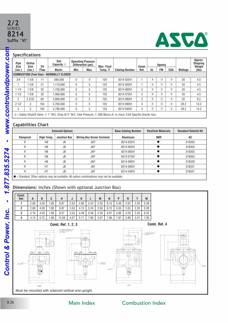
Solenoid Options Base Catalog Number Resilient Materials Standard Rebuild Kit
Rainproof High Temp. Junction Box Wiring Box Screw Terminal Aluminum NBR AC
R HB JB JKP 8214 035VI � 318303
R HB JB JKP 8214 050VI � 318303
R HB JB JKP 8214 060VI � 318303
R HB JB JKP 8214 070VI � 318303
R HB JB JKP 8214 080VI � 318328
R HT JB JKF 8214 090VI � 318331
R HT JB JKF 8214 040VI � 318331
Specifications
Dimensions: inches (Shown with optional Junction Box)
Const. Ref. 1, 2, 3 Const. Ref. 4
NPT
BOTH ENDS
PIPE PLUG
4 PLACES
7/8" DIAMETER KNOCKOUT FOR
1/2" CONDUIT CONNECTION
(BOTH SIDES)
N
H
W
T
P
K
B
J
M
R
C
L
A
FLOW
INSTRUCTION CARD
SHUT
OPEN
NPT
BOTH ENDS
PIPE PLUG
4 PLACES
7/8" DIAMETER KNOCKOUT FOR
1/2" CONDUIT CONNECTION
(BOTH SIDES)
K
W
T
L
H
P
R
CM
J
B
N
A E
FLOW
O TU
INSTRUCTION CARD
SHUT
OPEN
2/2SERIES8214Suffix ”VI” 4
Capabilities Chart
Must be mounted with solenoid vertical and upright.
8.26
� = Standard. Other options may be available. All option combinations may not be available.
PipeSize(ins.)
OrificeSize(ins.)
CVFlow
GasCapacity �
Operating PressureDifferential (psi)
Max. FluidTemp.˚F Catalog Number
Const.Ref.
Agency
Wattage
Approx.ShippingWeight(lbs)Btu/hr. Min. Max. UL FM CSA
COMBUSTION (Fuel Gas) - NORMALLY CLOSED
3/4 1 5/8 11 580,000 0 5 125 8214 035VI 1 � � � 20 4.5
1 1 5/8 21 1,119,000 0 5 125 8214 050VI 1 � � � 20 4.5
1 1/4 1 5/8 32 1,730,000 0 5 125 8214 060VI 2 � � � 20 4.5
1 1/2 1 5/8 35 1,900,000 0 5 125 8214 070VI 2 � � � 20 4.5
2 2 3/32 60 2,800,000 0 5 125 8214 080VI 3 � � � 20 6.5
2 1/2 3 104 5,765,500 0 5 125 8214 090VI 4 � � � 28.2 13.2
3 3 105 5,796,000 0 5 125 8214 040VI 4 � � � 28.2 14.2
� = Safety Shutoff Valve. � 1” W.C. Drop @ 2” W.C. Inlet Pressure, 1, 000 Btu/cu.ft. or more, 0.64 Specific Gravity Gas.
Const.Ref. A B C H J K L M N P R T W
1 2.69 4.59 1.88 8.97 3.53 4.06 5.24 2.50 6.15 5.46 2.62 2.20 5.39
2 2.69 4.59 1.88 8.97 3.53 4.13 5.24 2.50 6.15 5.53 2.62 2.20 5.39
3 3.16 4.59 1.88 9.57 3.53 4.49 6.56 2.50 6.81 5.89 3.28 2.20 6.32
4 4.13 5.72 1.88 12.59 4.07 5.71 7.80 3.07 7.96 7.87 3.89 3.31 7.95
Main Index Combustion Index
Co
ntr
ol
& P
ow
er,
In
c.
-
1.8
77.8
35.5
274
-
ww
w.c
on
tro
lan
dp
ow
er.
co
m
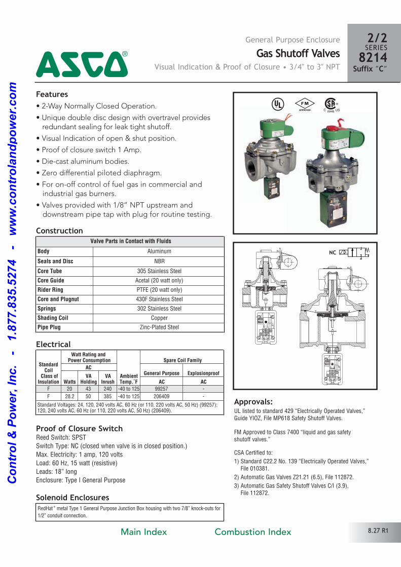
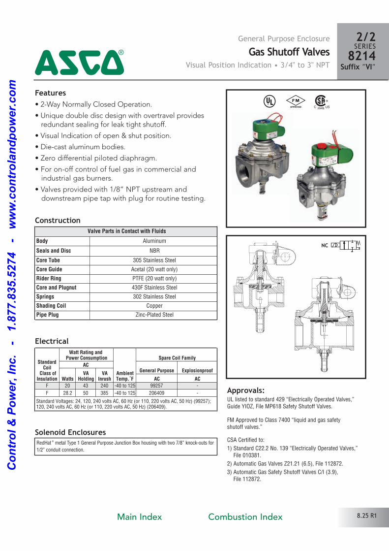
Features• 2Way Normally Closed Operation.
• Unique double disc design with overtravel providesredundant sealing for leak tight shutoff.
• Visual Indication of open & shut position.
• Proof of closure switch 1 Amp.
• Diecast aluminum bodies.
• Zero differential piloted diaphragm.
• For onoff control of fuel gas in commercial and industrial gas burners.
• Valves provided with 1/8” NPT upstream and downstream pipe tap with plug for routine testing.
Solenoid Enclosures
Construction
Electrical
Approvals:UL listed to standard 429 “Electrically Operated Valves,”Guide YIOZ, File MP618 Safety Shutoff Valves.
FM Approved to Class 7400 “liquid and gas safety shutoff valves.”
CSA Certified to:
1) Standard C22.2 No. 139 “Electrically Operated Valves,” File 010381.
2) Automatic Gas Valves Z21.21 (6.5), File 112872.
3) Automatic Gas Safety Shutoff Valves C/I (3.9), File 112872.
RedHat ® metal Type 1 General Purpose Junction Box housing with two 7/8” knockouts for
1/2” conduit connection.
NC
General Purpose EnclosureGas Shutoff Valves
Visual Indication & Proof of Closure • 3/4" to 3" NPT
2/2SERIES8214
Suffix ”C”4
8.27 R1
^ #
Proof of Closure SwitchReed Switch: SPST
Switch Type: NC (closed when valve is in closed position.)
Max. Electricity: 1 amp, 120 volts
Load: 60 Hz, 15 watt (resistive)
Leads: 18” long
Enclosure: Type I General Purpose
Valve Parts in Contact with Fluids
Body Aluminum
Seals and Disc NBR
Core Tube 305 Stainless Steel
Core Guide Acetal (20 watt only)
Rider Ring PTFE (20 watt only)
Core and Plugnut 430F Stainless Steel
Springs 302 Stainless Steel
Shading Coil Copper
Pipe Plug ZincPlated Steel
StandardCoil
Class ofInsulation
Watt Rating and Power Consumption
AmbientTemp.˚F
Spare Coil Family
ACGeneral Purpose Explosionproof
WattsVA
HoldingVA
Inrush AC AC
F 20 43 240 40 to 125 99257
F 28.2 50 385 40 to 125 206409
Standard Voltages: 24, 120, 240 volts AC, 60 Hz (or 110, 220 volts AC, 50 Hz) (99257); 120, 240 volts AC, 60 Hz (or 110, 220 volts AC, 50 Hz) (206409).
Main Index Combustion Index
Co
ntr
ol
& P
ow
er,
In
c.
-
1.8
77.8
35.5
274
-
ww
w.c
on
tro
lan
dp
ow
er.
co
m
Solenoid Options Base Catalog Number Resilient Materials Standard Rebuild Kit
High Temp. Junction Box Wiring Box Screw Terminal Aluminum NBR AC
HB JB JKP 8214 035C � 318303
HB JB JKP 8214 050C � 318303
HB JB JKP 8214 060C � 318303
HB JB JKP 8214 070C � 318303
HB JB JKP 8214 080C � 318328
HT JB JKF 8214 090C � 318330
HT JB JKF 8214 040C � 318330
PipeSize(ins.)
OrificeSize(ins.)
CVFlow
GasCapacity �
Operating PressureDifferential (psi)
Max. FluidTemp.˚F Catalog Number
Const.Ref.
Agency
Wattage
Approx.ShippingWeight(lbs)Btu/hr. Min. Max. UL FM CSA
COMBUSTION (Fuel Gas) - NORMALLY CLOSED
3/4 1 5/8 11 580,000 0 5 125 8214 035C 1 � � � 20 4.8
1 1 5/8 21 1,119,000 0 5 125 8214 050C 1 � � � 20 4.8
1 1/4 1 5/8 32 1,730,000 0 5 125 8214 060C 2 � � � 20 4.8
1 1/2 1 5/8 35 1,900,000 0 5 125 8214 070C 2 � � � 20 4.8
2 2 3/32 60 2,800,000 0 5 125 8214 080C 3 � � � 20 6.8
2 1/2 3 104 5,765,500 0 5 125 8214 090C 4 � � � 28.2 13.5
3 3 105 5,796,000 0 5 125 8214 040C 4 � � � 28.2 14.5
Specifications
Dimensions: inches (Shown with optional Junction Box)
Const. Ref. 1, 2, 3 Const. Ref. 4
NPT
BOTH ENDS
PIPE PLU
4 PLACE
7/8" DIAMETER KNOCKOUT FOR
1/2" CONDUIT CONNECTION
(BOTH SIDES)
H
W
U
F
Y
P
K
L
T
J
M
B
C
R
G
N
A E
FLOW
INSTRUCTION CARD
NPT
BOTH ENDS
PIPE PLUG
4 PLACES
7/8" DIAMETER KNOCKOUT FOR
1/2" CONDUIT CONNECTION
(BOTH SIDES)
H
K
W
Y
F
U
P
T
L
B
J
M
N
G
C
R
A E
FLOW
O TU
INSTRUCTION CARD
2/2SERIES8214Suffix ”C” 4
Capabilities Chart
Must be mounted with solenoid vertical and upright.
8.28 R1
� = Standard. Other options may be available. All option combinations may not be available.
� = Safety Shutoff Valve. � 1” W.C. Drop @ 2” W.C. Inlet Pressure, 1, 000 Btu/cu.ft. or more, 0.64 Specific Gravity Gas.
Const.Ref. A B C E F G H J K L M N P R T U W Y
1 2.69 4.59 1.88 2.69 2.75 2.44 10.54 3.53 4.06 5.00 2.50 6.15 5.46 2.62 2.20 1.12 5.39 1.63
2 2.69 4.59 1.88 2.69 2.75 2.44 10.54 3.53 4.13 5.00 2.50 6.15 5.53 2.62 2.20 1.12 5.39 1.63
3 3.16 4.59 1.88 3.16 2.75 2.44 11.15 3.53 4.49 6.09 2.50 6.81 5.89 3.28 2.20 1.12 6.32 1.63
4 4.13 5.72 1.88 3.82 2.75 2.44 14.25 4.07 5.71 7.80 3.07 7.96 7.87 3.89 3.31 1.12 7.95 1.63
Main Index Combustion Index
Co
ntr
ol
& P
ow
er,
In
c.
-
1.8
77.8
35.5
274
-
ww
w.c
on
tro
lan
dp
ow
er.
co
m
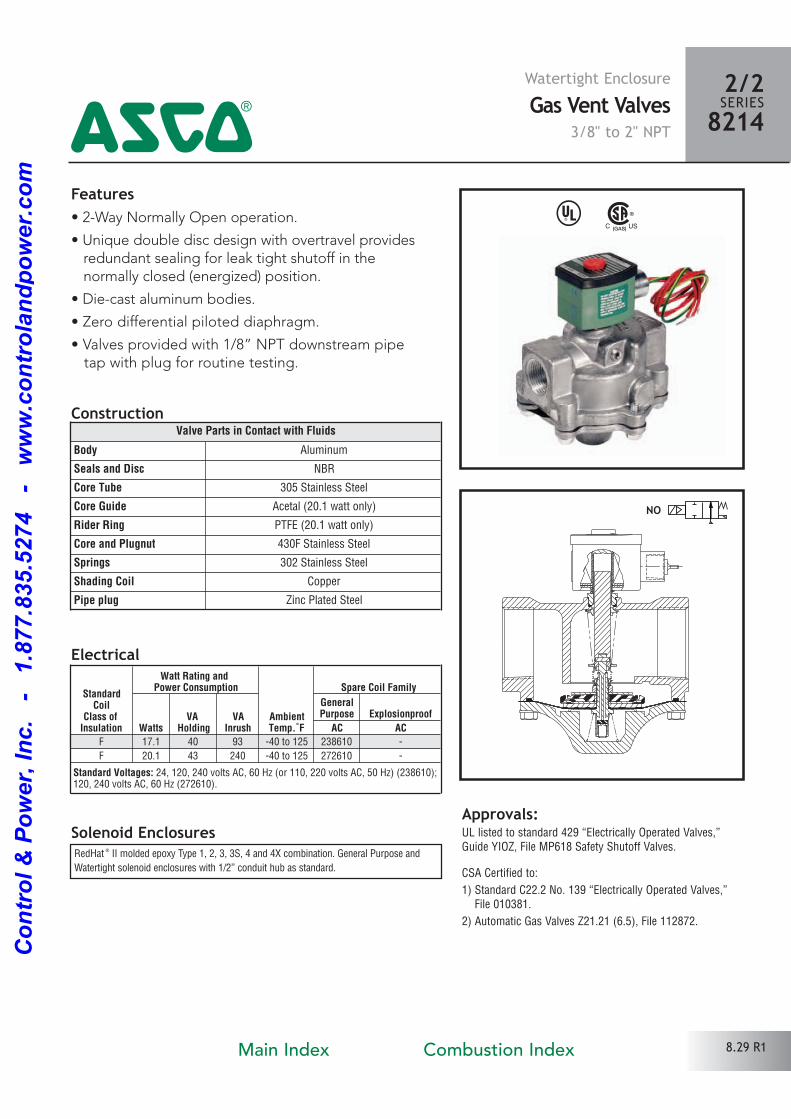
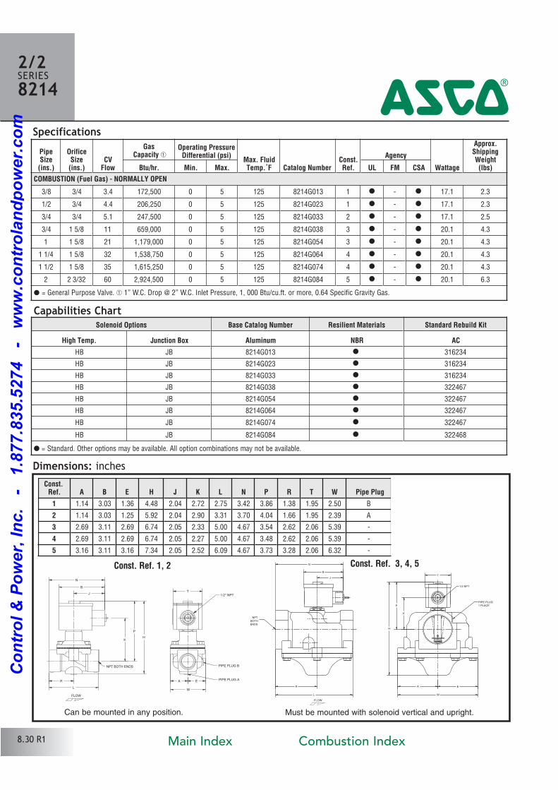
Watertight EnclosureGas Vent Valves
3/8" to 2" NPT
2/2SERIES82144
Features• 2Way Normally Open operation.
• Unique double disc design with overtravel providesredundant sealing for leak tight shutoff in the normally closed (energized) position.
• Diecast aluminum bodies.
• Zero differential piloted diaphragm.
• Valves provided with 1/8” NPT downstream pipe tap with plug for routine testing.
Solenoid Enclosures
Construction
Electrical
Approvals:UL listed to standard 429 “Electrically Operated Valves,”Guide YIOZ, File MP618 Safety Shutoff Valves.
CSA Certified to:
1) Standard C22.2 No. 139 “Electrically Operated Valves,” File 010381.
2) Automatic Gas Valves Z21.21 (6.5), File 112872.
NO
8.29 R1
RedHat ® II molded epoxy Type 1, 2, 3, 3S, 4 and 4X combination. General Purpose and
Watertight solenoid enclosures with 1/2” conduit hub as standard.
^
Valve Parts in Contact with Fluids
Body Aluminum
Seals and Disc NBR
Core Tube 305 Stainless Steel
Core Guide Acetal (20.1 watt only)
Rider Ring PTFE (20.1 watt only)
Core and Plugnut 430F Stainless Steel
Springs 302 Stainless Steel
Shading Coil Copper
Pipe plug Zinc Plated Steel
StandardCoil
Class of Insulation
Watt Rating and Power Consumption
AmbientTemp.˚F
Spare Coil Family
WattsVA
HoldingVA
Inrush
GeneralPurpose Explosionproof
AC ACF 17.1 40 93 40 to 125 238610
F 20.1 43 240 40 to 125 272610
Standard Voltages: 24, 120, 240 volts AC, 60 Hz (or 110, 220 volts AC, 50 Hz) (238610); 120, 240 volts AC, 60 Hz (272610).
Main Index Combustion Index
Co
ntr
ol
& P
ow
er,
In
c.
-
1.8
77.8
35.5
274
-
ww
w.c
on
tro
lan
dp
ow
er.
co
m
Solenoid Options Base Catalog Number Resilient Materials Standard Rebuild Kit
High Temp. Junction Box Aluminum NBR AC
HB JB 8214G013 � 316234
HB JB 8214G023 � 316234
HB JB 8214G033 � 316234
HB JB 8214G038 � 322467
HB JB 8214G054 � 322467
HB JB 8214G064 � 322467
HB JB 8214G074 � 322467
HB JB 8214G084 � 322468
PipeSize(ins.)
OrificeSize(ins.)
CVFlow
GasCapacity �
Operating PressureDifferential (psi)
Max. FluidTemp.˚F Catalog Number
Const.Ref.
Agency
Wattage
Approx.ShippingWeight(lbs)Btu/hr. Min. Max. UL FM CSA
COMBUSTION (Fuel Gas) - NORMALLY OPEN
3/8 3/4 3.4 172,500 0 5 125 8214G013 1 � � 17.1 2.3
1/2 3/4 4.4 206,250 0 5 125 8214G023 1 � � 17.1 2.3
3/4 3/4 5.1 247,500 0 5 125 8214G033 2 � � 17.1 2.5
3/4 1 5/8 11 659,000 0 5 125 8214G038 3 � � 20.1 4.3
1 1 5/8 21 1,179,000 0 5 125 8214G054 3 � � 20.1 4.3
1 1/4 1 5/8 32 1,538,750 0 5 125 8214G064 4 � � 20.1 4.3
1 1/2 1 5/8 35 1,615,250 0 5 125 8214G074 4 � � 20.1 4.3
2 2 3/32 60 2,924,500 0 5 125 8214G084 5 � � 20.1 6.3
Specifications
2/2SERIES8214
4
� = General Purpose Valve. � 1” W.C. Drop @ 2” W.C. Inlet Pressure, 1, 000 Btu/cu.ft. or more, 0.64 Specific Gravity Gas.
Capabilities Chart
� = Standard. Other options may be available. All option combinations may not be available.
1/2 NPT
J
B
N
R
L
A
W
T
K
P
H
E
NPT
BOTH
ENDS
PIPE PLUG
1 PLACE
FLOW
Dimensions: inches
8.30 R1
Must be mounted with solenoid vertical and upright.
Const. Ref. 1, 2 Const. Ref. 3, 4, 5
FLOW
L
T
HK
P
B
J
N
R A PIPE PLUG A
PIPE PLUG B
E
W
NPT BOTH ENDS
1/2" NPT
Can be mounted in any position.
Const.Ref. A B E H J K L N P R T W Pipe Plug
1 1.14 3.03 1.36 4.48 2.04 2.72 2.75 3.42 3.86 1.38 1.95 2.50 B
2 1.14 3.03 1.25 5.92 2.04 2.90 3.31 3.70 4.04 1.66 1.95 2.39 A
3 2.69 3.11 2.69 6.74 2.05 2.33 5.00 4.67 3.54 2.62 2.06 5.39
4 2.69 3.11 2.69 6.74 2.05 2.27 5.00 4.67 3.48 2.62 2.06 5.39
5 3.16 3.11 3.16 7.34 2.05 2.52 6.09 4.67 3.73 3.28 2.06 6.32
Main Index Combustion Index
Co
ntr
ol
& P
ow
er,
In
c.
-
1.8
77.8
35.5
274
-
ww
w.c
on
tro
lan
dp
ow
er.
co
m
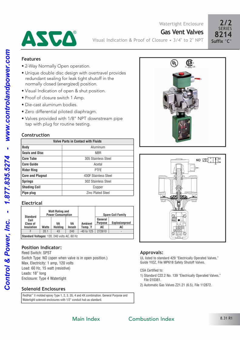
Watertight EnclosureGas Vent Valves
Visual Indication & Proof of Closure • 3/4" to 2" NPT
2/2SERIES8214
Suffix ”C”4Features• 2Way Normally Open operation.
• Unique double disc design with overtravel providesredundant sealing for leak tight shutoff in the normally closed (energized) position.
• Visual Indication of open & shut position.
• Proof of closure switch 1 Amp.
• Diecast aluminum bodies.
• Zero differential piloted diaphragm.
• Valves provided with 1/8” NPT downstream pipe tap with plug for routine testing.
Solenoid Enclosures
Construction
Electrical
Position Indicator:Reed Switch: SPST
Switch Type: NO (open when valve is in open position.)
Max. Electricity: 1 amp, 120 volts
Load: 60 Hz, 15 watt (resistive)
Leads: 18” long
Enclosure: Type 4 Watertight
Approvals:UL listed to standard 429 “Electrically Operated Valves,”Guide YIOZ, File MP618 Safety Shutoff Valves.
CSA Certified to:
1) Standard C22.2 No. 139 “Electrically Operated Valves,” File 010381.
2) Automatic Gas Valves Z21.21 (6.5), File 112872.
NO
8.31 R1
Valve Parts in Contact with Fluids
Body Aluminum
Seals and Disc NBR
Core Tube 305 Stainless Steel
Core Guide Acetal
Rider Ring PTFE
Core and Plugnut 430F Stainless Steel
Springs 302 Stainless Steel
Shading Coil Copper
Pipe plug Zinc Plated Steel
StandardCoil
Class of Insulation
Watt Rating and Power Consumption
AmbientTemp.˚F
Spare Coil Family
WattsVA
HoldingVA
Inrush
GeneralPurpose Explosionproof
AC ACF 20.1 43 240 40 to 125 272610
Standard Voltages: 120, 240 volts AC, 60 Hz
^
RedHat ® II molded epoxy Type 1, 2, 3, 3S, 4 and 4X combination. General Purpose and
Watertight solenoid enclosures with 1/2” conduit hub as standard.
Main Index Combustion Index
Co
ntr
ol
& P
ow
er,
In
c.
-
1.8
77.8
35.5
274
-
ww
w.c
on
tro
lan
dp
ow
er.
co
m
Solenoid Options Base Catalog Number Resilient Materials Standard Rebuild Kit
High Temp. Junction Box Aluminum NBR AC
HB JB 8214G038C � 322469
HB JB 8214G054C � 322469
HB JB 8214G064C � 322469
HB JB 8214G074C � 322469
HB JB 8214G084C � 322470
PipeSize(ins.)
OrificeSize(ins.)
CVFlow
GasCapacity �
Operating PressureDifferential (psi)
Max. FluidTemp.˚F Catalog Number
Const.Ref.
Agency
Wattage
Approx.ShippingWeight(lbs)Btu/hr. Min. Max. UL FM CSA
COMBUSTION (Fuel Gas) - NORMALLY OPEN
3/4 1 5/8 11 659,000 0 5 125 8214G038C 1 � � 20.1 4.8
1 1 5/8 21 1,179,000 0 5 125 8214G054C 1 � � 20.1 4.8
1 1/4 1 5/8 32 1,538,750 0 5 125 8214G064C 2 � � 20.1 4.8
1 1/2 1 5/8 35 1,615,250 0 5 125 8214G074C 2 � � 20.1 4.8
2 2 3/32 60 2,924,500 0 5 125 8214G084C 3 � � 20.1 6.8
Specifications
2/2SERIES8214Suffix ”C” 4
� = General Purpose Valve. � 1” W.C. Drop @ 2” W.C. Inlet Pressure, 1, 000 Btu/cu.ft. or more, 0.64 Specific Gravity Gas.
Capabilities Chart
� = Standard. Other options may be available. All option combinations may not be available.
PIPE PLUG1 PLACE
1/2" NPT
NPTBOTH ENDS
F
Y
W
U
K
P
H
L
J
B
R
GA
N
E
FLOW
Dimensions: inches
8.32 R1
Must be mounted with solenoid vertical and upright.
Const. Ref. 1, 2, 3
Const.Ref. A B F G H J K L N P R U W Y
1 2.69 3.11 3.07 2.32 10.54 2.05 4.06 5.00 4.67 5.46 2.62 1.18 5.39 1.69
2 2.69 3.11 3.07 2.32 10.54 2.05 4.13 5.00 4.67 5.53 2.62 1.18 5.39 1.69
3 3.16 3.11 3.07 2.32 11.33 2.05 4.62 6.09 5.33 5.84 3.28 1.18 6.32 1.69
Main Index Combustion Index
Co
ntr
ol
& P
ow
er,
In
c.
-
1.8
77.8
35.5
274
-
ww
w.c
on
tro
lan
dp
ow
er.
co
m
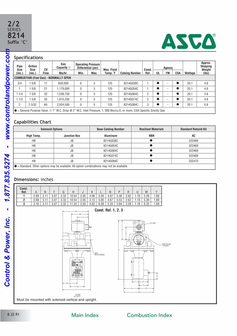
Features• 2Way Normally Open operation.
• Unique double disc design with overtravel providesredundant sealing for leak tight shutoff in the normally closed (energized) position.
• Diecast aluminum bodies.
• Zero differential piloted diaphragm.
• Valves provided with 1/8” NPT downstream pipe
tap with plug for routine testing.
Solenoid Enclosures
Construction
Electrical
^
Approvals:UL listed to standard 429 “Electrically Operated Valves,” Guide YIOZ, File MP618 General Purpose Valves.
CSA Certified to:
1) Standard C22.2 No. 139 “Electrically Operated Valves,” File 010381.
2) Automatic Gas Valves Z21.21 (6.5), File 112872.
Valve Parts in Contact with Fluids
Body Aluminum
Seals and Disc NBR
Core Tube 305 Stainless Steel
Core Guide Acetal (20 watt only)
Rider Ring PTFE (20 watt only)
Core and Plugnut 430F Stainless Steel
Springs 302 Stainless Steel
Shading Coil Copper
Pipe Plug Zinc plated steel
RedHat ® Metal Type 1 General Purpose Junction Box housing with two 7/8” knockouts for conduit connection.
NO
General Purpose EnclosureGas Vent Valves
3/4" to 2 1/2" NPT
2/2SERIES82144
StandardCoil
Class ofInsulation
Watt Rating and Power Consumption
AmbientTemp.˚F
Spare Coil Family
ACGeneral Purpose Explosionproof
WattsVA
HoldingVA
Inrush AC ACF 20 43 240 40 to 125 99257
F 28.2 50 385 40 to 125 206409
Standard Voltages: 24, 120, 240 volts AC, 60 Hz (or 110, 220 volts AC, 50 Hz) (99257); 120, 240 volts AC, 60 Hz (or 110, 220 volts AC, 50 Hz) (206409).
8.33 R1Main Index Combustion Index
Co
ntr
ol
& P
ow
er,
In
c.
-
1.8
77.8
35.5
274
-
ww
w.c
on
tro
lan
dp
ow
er.
co
m
Specifications
Dimensions: inches (Shown with optional Junction Box)
Const. Ref. 1, 2
PipeSize(ins.)
OrificeSize(ins.)
CVFlow
GasCapacity �
Operating PressureDifferential (psi)
Max. FluidTemp.˚F Catalog Number
Const.Ref.
Agency
Wattage
Approx.ShippingWeight(lbs)Btu/hr. Min. Max. UL FM CSA
COMBUSTION (Fuel Gas) - NORMALLY OPEN
3/4 1 5/8 11 659,000 0 5 125 8214 037 1 � � 20 4.3
1 1 5/8 21 1,179,000 0 5 125 8214 053 1 � � 20 4.3
1 1/4 1 5/8 32 1,538,750 0 5 125 8214 063 2 � � 20 4.3
1 1/2 1 5/8 35 1,615,250 0 5 125 8214 073 2 � � 20 4.3
2 2 3/32 60 2,924,500 0 5 125 8214 083 3 � � 20 6.3
2 1/2 3 109 6,022,750 0 5 125 8214 093 4 � � 28.2 13.0
NPT
BOTHENDS
PIPE PLUG1 PLACE
7/8" DIAMETER KNOCKOUT
FOR 1/2" CONDUIT
CONNECTION (BOTH SIDES)
W
H
P
K
L
TB
J
M
R
N
C
A E
FLOW
NPT
BOTHENDS
PIPE PLUG2 PLACES
K
T
N W
H
P
L
R
M
B
J
C
A E
FLOW
INSTRUCTION CARD
7/8" DIAMETER KNOCKOUT
FOR 1/2" CONDUIT
CONNECTION (BOTH SIDES)
Const. Ref. 3, 4
Const.Ref. A B C E H J K L M N P R T W
1 2.69 4.59 1.88 2.69 6.79 3.53 2.19 5.00 2.50 6.16 3.59 2.62 2.20 5.39
2 2.69 4.59 1.88 2.69 6.79 3.53 2.13 5.00 2.50 6.16 3.53 2.62 2.20 5.39
3 3.16 4.59 1.88 3.16 7.39 3.53 2.38 6.09 2.50 6.34 3.78 2.81 2.20 6.32
4 3.82 5.72 1.88 4.13 10.33 4.07 3.07 7.80 3.07 7.97 5.13 3.89 3.31 3.95
2/2SERIES8214 4
Capabilities Chart� = General Purpose Valve. � 1” W.C. Drop @ 2” W.C. Inlet Pressure, 1, 000 Btu/cu.ft. or more, 0.64 Specific Gravity Gas.
Solenoid Options Base Catalog Number Resilient Materials Standard Rebuild Kit
Rainproof High Temp. Junction Box Aluminum NBR AC
R HB JB 8214 037 � 316728
R HB JB 8214 053 � 316728
R HB JB 8214 063 � 316728
R HB JB 8214 073 � 316728
R HB JB 8214 083 � 316727
R HT JB 8214 093 � 316776
Must be mounted with solenoid vertical and upright.
8.34 R1
� = Standard. Other options may be available. All option combinations may not be available.
Main Index Combustion Index
Co
ntr
ol
& P
ow
er,
In
c.
-
1.8
77.8
35.5
274
-
ww
w.c
on
tro
lan
dp
ow
er.
co
m
General Purpose EnclosureGas Vent Valves
Visual Indication & Proof of Closure • 3/4" to 2" NPT
2/2SERIES8214
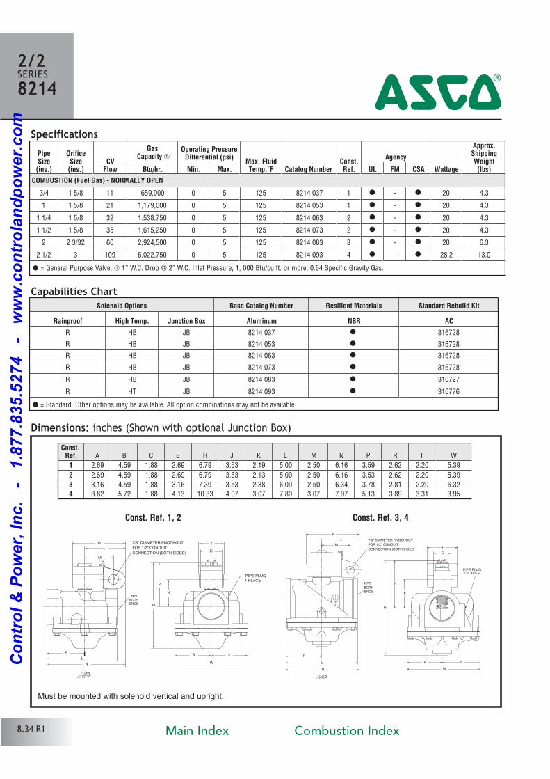
Suffix ”C”4Features• 2Way Normally Open operation.
• Unique double disc design with overtravel providesredundant sealing for leak tight shutoff in the normally closed (energized) position.
• Visual Indication of open & shut position.
• Proof of closure switch 1 Amp.
• Diecast aluminum bodies.
• Zero differential piloted diaphragm.
• Valves provided with 1/8” NPT downstream pipe tap with plug for routine testing.
Solenoid Enclosures
Construction
Electrical
RedHat ® metal Type 1 General Purpose Junction Box housing with two 7/8” knockouts for
1/2” conduit connection.
Position Indicator:Reed Switch: SPST
Switch Type: NO (open when valve is in open position.)
Max. Electricity: 1 amp, 120 volts
Load: 60 Hz, 15 watt (resistive)
Leads: 18” long
Enclosure: Type I General Purpose
Approvals:UL listed to standard 429 “Electrically Operated Valves,”Guide YIOZ, File MP618 Safety Shutoff Valves.
CSA Certified to:
1) Standard C22.2 No. 139 “Electrically Operated Valves,” File 010381.
2) Automatic Gas Valves Z21.21 (6.5), File 112872.
OPEN
SHUT
NO
Valve Parts in Contact with Fluids
Body Aluminum
Seals and Disc NBR
Core Tube 305 Stainless Steel
Core Guide Acetal
Rider Ring PTFE
Core and Plugnut 430F Stainless Steel
Springs 302 Stainless Steel
Shading Coil Copper
Pipe plug Zinc Plated Steel
StandardCoil
Class of Insulation
Watt Rating and Power Consumption
AmbientTemp.˚F
Spare Coil Family
WattsVA
HoldingVA
Inrush
GeneralPurpose Explosionproof
AC ACF 20 43 240 40 to 125 99257
Standard Voltages: 24, 120, 240 volts AC, 60 Hz (or 110, 220 volts AC, 50 Hz) (99257)
8.35 R1
^
Main Index Combustion Index
Co
ntr
ol
& P
ow
er,
In
c.
-
1.8
77.8
35.5
274
-
ww
w.c
on
tro
lan
dp
ow
er.
co
m
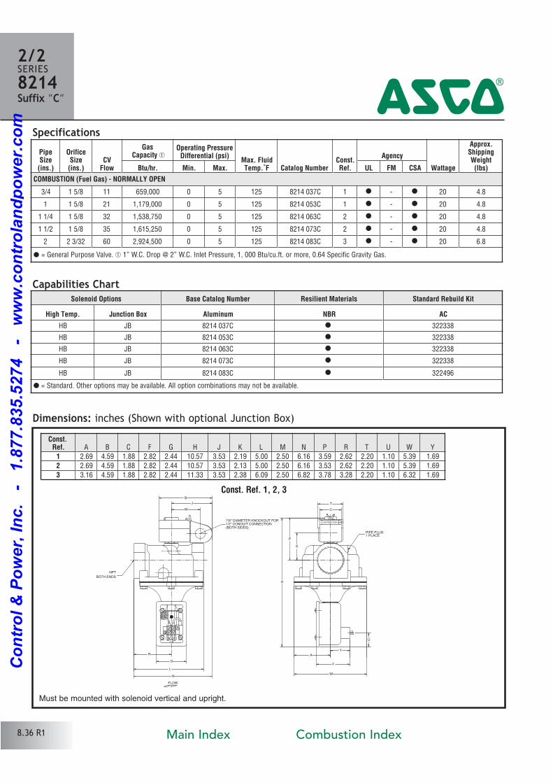
PipeSize(ins.)
OrificeSize(ins.)
CVFlow
GasCapacity �
Operating PressureDifferential (psi)
Max. FluidTemp.˚F Catalog Number
Const.Ref.
Agency
Wattage
Approx.ShippingWeight(lbs)Btu/hr. Min. Max. UL FM CSA
COMBUSTION (Fuel Gas) - NORMALLY OPEN
3/4 1 5/8 11 659,000 0 5 125 8214 037C 1 � � 20 4.8
1 1 5/8 21 1,179,000 0 5 125 8214 053C 1 � � 20 4.8
1 1/4 1 5/8 32 1,538,750 0 5 125 8214 063C 2 � � 20 4.8
1 1/2 1 5/8 35 1,615,250 0 5 125 8214 073C 2 � � 20 4.8
2 2 3/32 60 2,924,500 0 5 125 8214 083C 3 � � 20 6.8
Solenoid Options Base Catalog Number Resilient Materials Standard Rebuild Kit
High Temp. Junction Box Aluminum NBR AC
HB JB 8214 037C � 322338
HB JB 8214 053C � 322338
HB JB 8214 063C � 322338
HB JB 8214 073C � 322338
HB JB 8214 083C � 322496
Specifications
2/2SERIES8214Suffix ”C” 4
� = General Purpose Valve. � 1” W.C. Drop @ 2” W.C. Inlet Pressure, 1, 000 Btu/cu.ft. or more, 0.64 Specific Gravity Gas.
Capabilities Chart
� = Standard. Other options may be available. All option combinations may not be available.
NPT
BOTH ENDS
PIPE PLUG1 PLACE
7/8" DIAMETER KNOCKOUT FOR1/2" CONDUIT CONNECTION(BOTH SIDES)
T
L
K
P
H
W
U
F
Y
M
J
B
R
G
C
N
A
FLOW
INSTRUCTION CARD
Dimensions: inches (Shown with optional Junction Box)
8.36 R1
Const.Ref. A B C F G H J K L M N P R T U W Y
1 2.69 4.59 1.88 2.82 2.44 10.57 3.53 2.19 5.00 2.50 6.16 3.59 2.62 2.20 1.10 5.39 1.69
2 2.69 4.59 1.88 2.82 2.44 10.57 3.53 2.13 5.00 2.50 6.16 3.53 2.62 2.20 1.10 5.39 1.69
3 3.16 4.59 1.88 2.82 2.44 11.33 3.53 2.38 6.09 2.50 6.82 3.78 3.28 2.20 1.10 6.32 1.69
Must be mounted with solenoid vertical and upright.
Const. Ref. 1, 2, 3
Main Index Combustion Index
Co
ntr
ol
& P
ow
er,
In
c.
-
1.8
77.8
35.5
274
-
ww
w.c
on
tro
lan
dp
ow
er.
co
m
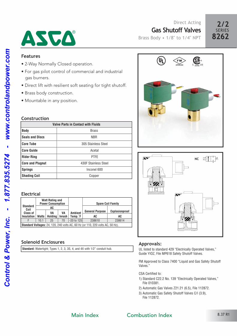
Direct ActingGas Shutoff Valves
Brass Body • 1/8" to 1/4" NPT
^ #Features• 2Way Normally Closed operation.
• For gas pilot control of commercial and industrial
gas burners.
• Direct lift with resilient soft seating for tight shutoff.
• Brass body construction.
• Mountable in any position.
Solenoid Enclosures
Electrical
Construction
Standard: Watertight; Types 1, 2, 3, 3S, 4, and 4X with 1/2” conduit hub.
Valve Parts in Contact with Fluids
Body Brass
Seals and Discs NBR
Core Tube 305 Stainless Steel
Core Guide Acetal
Rider Ring PTFE
Core and Plugnut 430F Stainless Steel
Springs Inconel 600
Shading Coil Copper
Approvals:UL listed to standard 429 “Electrically Operated Valves,”Guide YIOZ, File MP618 Safety Shutoff Valves.
FM Approved to Class 7400 “Liquid and Gas Safety ShutoffValves.”
CSA Certified to:
1) Standard C22.2 No. 139 “Electrically Operated Valves,” File 010381.
2) Automatic Gas Valves Z21.21 (6.5), File 112872.
3) Automatic Gas Safety Shutoff Valves C/I (3.9), File 112872.
2/2SERIES82624
StandardCoil
Class ofInsulation
Watt Rating and Power Consumption
AmbientTemp.˚F
Spare Coil Family
ACGeneral Purpose Explosionproof
WattsVA
HoldingVA
Inrush AC ACF 10.1 25 70 20 to 125 238610 238614
Standard Voltages: 24, 120, 240 volts AC, 60 Hz (or 110, 220 volts AC, 50 Hz).
8.37 R1Main Index Combustion Index
Co
ntr
ol
& P
ow
er,
In
c.
-
1.8
77.8
35.5
274
-
ww
w.c
on
tro
lan
dp
ow
er.
co
m
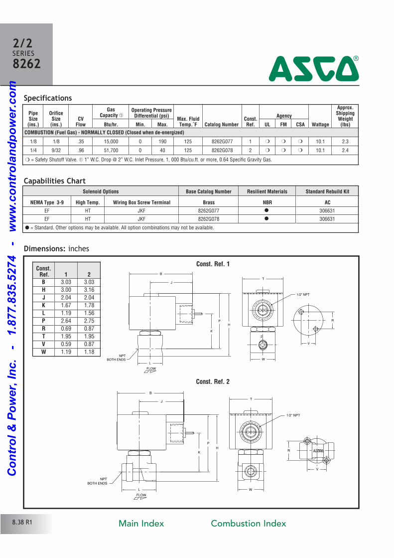
Dimensions: inches
NPTBOTH ENDS
1/2" NPT
T
L
K
PH
W
B
J
V
R
FLOW
2
Const. Ref. 1
Specifications
Const. Ref. 2
NPT
BOTH ENDS
1/2" NPT
T
B
J
R
V
K
P
H
L W
FLOW
Const. Ref. 1 2
B 3.03 3.03
H 3.00 3.16
J 2.04 2.04
K 1.67 1.78
L 1.19 1.56
P 2.64 2.75
R 0.69 0.87
T 1.95 1.95
V 0.59 0.87
W 1.19 1.18
2/2SERIES8262
4
PipeSize(ins.)
OrificeSize(ins.)
CVFlow
GasCapacity �
Operating PressureDifferential (psi)
Max. FluidTemp.˚F Catalog Number
Const.Ref.
Agency
Wattage
Approx.ShippingWeight(lbs)Btu/hr. Min. Max. UL FM CSA
COMBUSTION (Fuel Gas) - NORMALLY CLOSED (Closed when de-energized)
1/8 1/8 .35 15,000 0 190 125 8262G077 1 � � � 10.1 2.3
1/4 9/32 .96 51,700 0 40 125 8262G078 2 � � � 10.1 2.4
� = Safety Shutoff Valve. � 1” W.C. Drop @ 2” W.C. Inlet Pressure, 1, 000 Btu/cu.ft. or more, 0.64 Specific Gravity Gas.
Capabilities ChartSolenoid Options Base Catalog Number Resilient Materials Standard Rebuild Kit
NEMA Type 3-9 High Temp. Wiring Box Screw Terminal Brass NBR AC
EF HT JKF 8262G077 � 306631
EF HT JKF 8262G078 � 306631
8.38 R1
� = Standard. Other options may be available. All option combinations may not be available.
Main Index Combustion Index
Co
ntr
ol
& P
ow
er,
In
c.
-
1.8
77.8
35.5
274
-
ww
w.c
on
tro
lan
dp
ow
er.
co
m
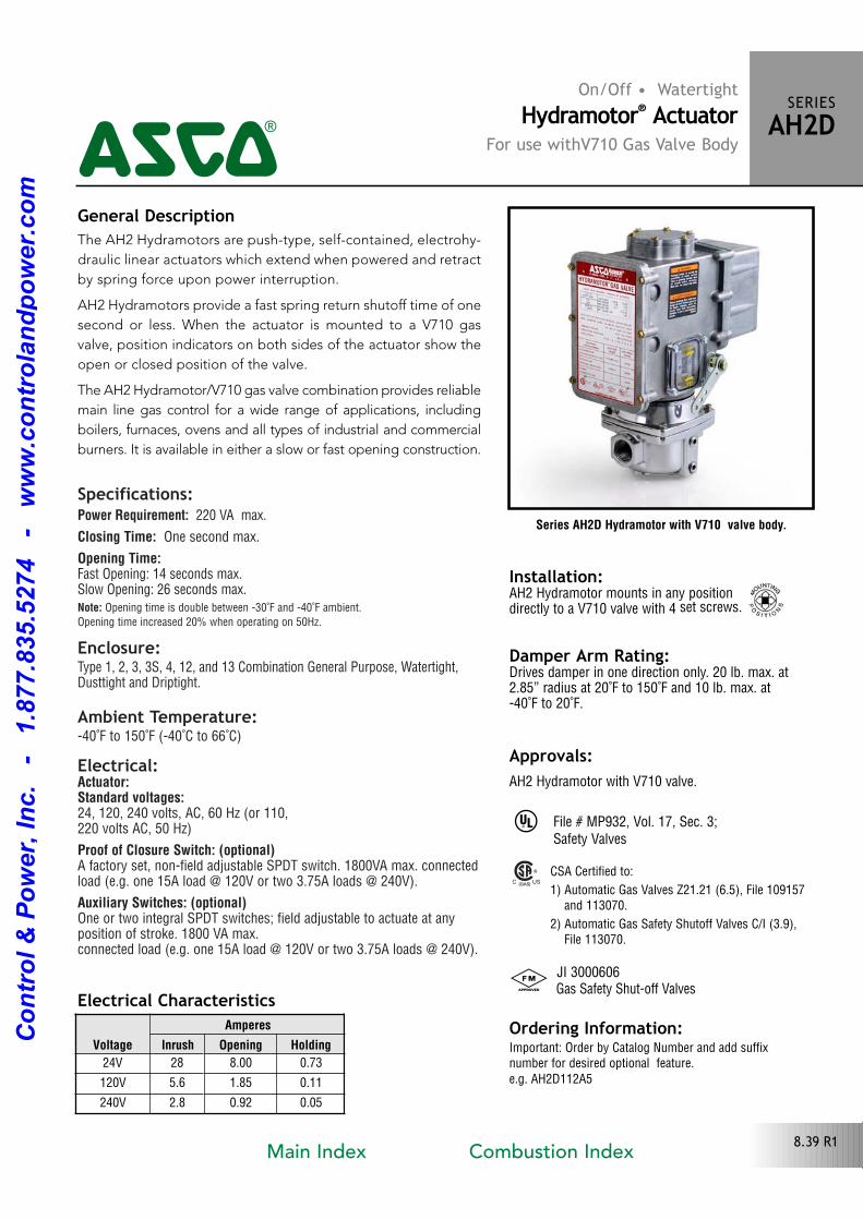
Specifications:Power Requirement: 220 VA max.
Closing Time: One second max.
Opening Time:Fast Opening: 14 seconds max.Slow Opening: 26 seconds max.Note: Opening time is double between 30˚F and 40˚F ambient.
Opening time increased 20% when operating on 50Hz.
Enclosure:Type 1, 2, 3, 3S, 4, 12, and 13 Combination General Purpose, Watertight, Dusttight and Driptight.
Ambient Temperature:40˚F to 150˚F (40˚C to 66˚C)
Electrical:Actuator:Standard voltages:24, 120, 240 volts, AC, 60 Hz (or 110, 220 volts AC, 50 Hz)
Proof of Closure Switch: (optional)A factory set, nonfield adjustable SPDT switch. 1800VA max. connectedload (e.g. one 15A load @ 120V or two 3.75A loads @ 240V).
Auxiliary Switches: (optional)One or two integral SPDT switches; field adjustable to actuate at any position of stroke. 1800 VA max. connected load (e.g. one 15A load @ 120V or two 3.75A loads @ 240V).
Series AH2D Hydramotor with V710 valve body.
Electrical Characteristics
Installation: AH2 Hydramotor mounts in any position directly to a V710 valve with 4 set screws.
Damper Arm Rating:Drives damper in one direction only. 20 lb. max. at2.85” radius at 20˚F to 150˚F and 10 lb. max. at 40˚F to 20˚F.
On/Off • WatertightHydramotor® Actuator
For use withV710 Gas Valve Body
SERIESAH2D4The AH2 Hydramotors are pushtype, selfcontained, electrohy
draulic linear actuators which extend when powered and retract
by spring force upon power interruption.
AH2 Hydramotors provide a fast spring return shutoff time of one
second or less. When the actuator is mounted to a V710 gas
valve, position indicators on both sides of the actuator show the
open or closed position of the valve.
The AH2 Hydramotor/V710 gas valve combination provides reliable
main line gas control for a wide range of applications, including
boilers, furnaces, ovens and all types of industrial and commercial
burners. It is available in either a slow or fast opening construction.
Voltage
Amperes
Inrush Opening Holding
24V 28 8.00 0.73
120V 5.6 1.85 0.11
240V 2.8 0.92 0.05
General Description
Approvals:AH2 Hydramotor with V710 valve.
^
# JI 3000606 Gas Safety Shutoff Valves
Ordering Information:Important: Order by Catalog Number and add suffixnumber for desired optional feature.e.g. AH2D112A5
CSA Certified to:
1) Automatic Gas Valves Z21.21 (6.5), File 109157 and 113070.
2) Automatic Gas Safety Shutoff Valves C/I (3.9), File 113070.
File # MP932, Vol. 17, Sec. 3;Safety Valves
8.39 R1Main Index Combustion Index
Co
ntr
ol
& P
ow
er,
In
c.
-
1.8
77.8
35.5
274
-
ww
w.c
on
tro
lan
dp
ow
er.
co
m
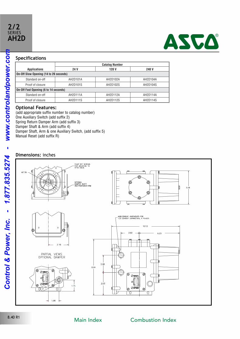
Specifications
Optional Features:(add appropriate suffix number to catalog number)One Auxiliary Switch (add suffix 2)Spring Return Damper Arm (add suffix 3)Damper Shaft & Arm (add suffix 4)Damper Shaft, Arm & one Auxiliary Switch, (add suffix 5)Manual Reset (add suffix R)
Dimensions: inches
2/2SERIESAH2D
4
8.40 R1
Applications
Catalog Number
24 V 120 V 240 V
On-Off Slow Opening (14 to 26 seconds)
Standard onoff AH2D101A AH2D102A AH2D104A
Proof of closure AH2D101S AH2D102S AH2D104S
On-Off Fast Opening (6 to 14 seconds)
Standard onoff AH2D111A AH2D112A AH2D114A
Proof of closure AH2D111S AH2D112S AH2D114S
Main Index Combustion Index
Co
ntr
ol
& P
ow
er,
In
c.
-
1.8
77.8
35.5
274
-
ww
w.c
on
tro
lan
dp
ow
er.
co
m
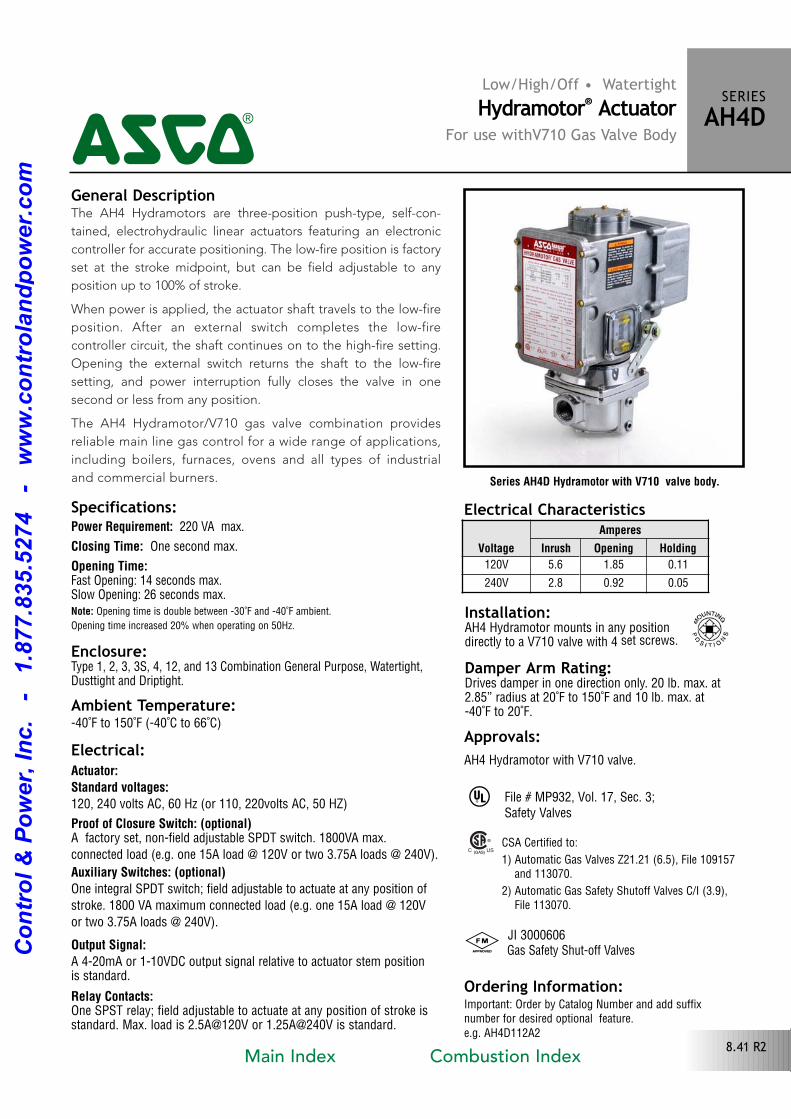
The AH4 Hydramotors are threeposition pushtype, selfcon
tained, electrohydraulic linear actuators featuring an electronic
controller for accurate positioning. The lowfire position is factory
set at the stroke midpoint, but can be field adjustable to any
position up to 100% of stroke.
When power is applied, the actuator shaft travels to the lowfire
position. After an external switch completes the lowfire
controller circuit, the shaft continues on to the highfire setting.
Opening the external switch returns the shaft to the lowfire
setting, and power interruption fully closes the valve in one
second or less from any position.
The AH4 Hydramotor/V710 gas valve combination provides
reliable main line gas control for a wide range of applications,
including boilers, furnaces, ovens and all types of industrial
and commercial burners. Series AH4D Hydramotor with V710 valve body.
Low/High/Off • WatertightHydramotor® Actuator
For use withV710 Gas Valve Body
SERIESAH4D4
Specifications:Power Requirement: 220 VA max.
Closing Time: One second max.
Opening Time:Fast Opening: 14 seconds max.Slow Opening: 26 seconds max.Note: Opening time is double between 30˚F and 40˚F ambient.
Opening time increased 20% when operating on 50Hz.
Enclosure:Type 1, 2, 3, 3S, 4, 12, and 13 Combination General Purpose, Watertight,Dusttight and Driptight.
Ambient Temperature:40˚F to 150˚F (40˚C to 66˚C)
Electrical:Actuator:Standard voltages: 120, 240 volts AC, 60 Hz (or 110, 220volts AC, 50 HZ)
Proof of Closure Switch: (optional)A factory set, nonfield adjustable SPDT switch. 1800VA max.
connected load (e.g. one 15A load @ 120V or two 3.75A loads @ 240V).
Auxiliary Switches: (optional)One integral SPDT switch; field adjustable to actuate at any position of
stroke. 1800 VA maximum connected load (e.g. one 15A load @ 120V
or two 3.75A loads @ 240V).
Output Signal:A 420mA or 110VDC output signal relative to actuator stem position is standard.
Relay Contacts:One SPST relay; field adjustable to actuate at any position of stroke is standard. Max. load is 2.5A@120V or 1.25A@240V is standard.
General Description
Installation: AH4 Hydramotor mounts in any position directly to a V710 valve with 4 set screws.
Damper Arm Rating:Drives damper in one direction only. 20 lb. max. at2.85” radius at 20˚F to 150˚F and 10 lb. max. at 40˚F to 20˚F.
Approvals:AH4 Hydramotor with V710 valve.
^
# JI 3000606 Gas Safety Shutoff Valves
Ordering Information:Important: Order by Catalog Number and add suffixnumber for desired optional feature.e.g. AH4D112A2
CSA Certified to:
1) Automatic Gas Valves Z21.21 (6.5), File 109157 and 113070.
2) Automatic Gas Safety Shutoff Valves C/I (3.9), File 113070.
File # MP932, Vol. 17, Sec. 3;Safety Valves
Electrical CharacteristicsVoltage
Amperes
Inrush Opening Holding
120V 5.6 1.85 0.11
240V 2.8 0.92 0.05
8.41 R2Main Index Combustion Index
Co
ntr
ol
& P
ow
er,
In
c.
-
1.8
77.8
35.5
274
-
ww
w.c
on
tro
lan
dp
ow
er.
co
m
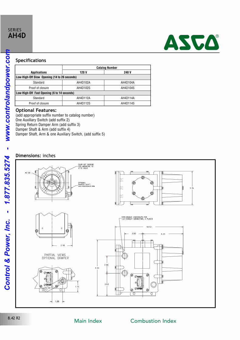
Optional Features:(add appropriate suffix number to catalog number)One Auxiliary Switch (add suffix 2)Spring Return Damper Arm (add suffix 3)Damper Shaft & Arm (add suffix 4)Damper Shaft, Arm & one Auxiliary Switch, (add suffix 5)
8.42 R2
Specifications
SERIESAH4D4
Dimensions: inches
Applications
Catalog Number
120 V 240 V
Low-High-Off Slow Opening (14 to 26 seconds)
Standard AH4D102A AH4D104A
Proof of closure AH4D102S AH4D104S
Low-High-Off Fast Opening (6 to 14 seconds)
Standard AH4D112A AH4D114A
Proof of closure AH4D112S AH4D114S
Main Index Combustion Index
Co
ntr
ol
& P
ow
er,
In
c.
-
1.8
77.8
35.5
274
-
ww
w.c
on
tro
lan
dp
ow
er.
co
m
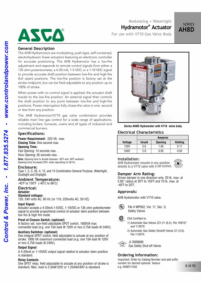
Installation: AH8 Hydramotor mounts in any position directly to a V710 valve with 4 set screws.
Series AH8D Hydramotor with V710 valve body.
Specifications:Power Requirement: 220 VA max.Closing Time: One second max.Opening Time:Fast Opening: 14 seconds max.Slow Opening: 26 seconds max.Note: Opening time is double between 30˚F and 40˚F ambient.Opening time increased 20% when operating on 50 Hz.
Enclosure:Type 1, 2, 3, 3S, 4, 12, and 13 Combination General Purpose, Watertight,Dusttight and Driptight.
Ambient Temperature:40˚F to 150˚F (40˚C to 66˚C)
Electrical:Actuator:Standard voltages: 120, 240 volts AC, 60 Hz (or 110, 220volts AC, 50 HZ)
Input Signal:Actuator accepts a 420mA,15VDC, 110VDC or 135 ohm potentiometersignal to provide proportional control of actuator stem position betweenlow fire & high fire mode.
Proof of Closure Switch: (optional)A factory set, nonfield adjustable SPDT switch. 1800VA max.connected load (e.g. one 15A load @ 120V or two 3.75A loads @ 240V).
Auxiliary Switches: (optional)One integral SPDT switch; field adjustable to actuate at any position ofstroke. 1800 VA maximum connected load (e.g. one 15A load @ 120V or two 3.75A loads @ 240V).
Output Signal: A 420mA or 110VDC output signal relative to actuator stem position is standard.
Relay Contacts: One SPST relay; field adjustable to actuate at any position of stroke is standard. Max. load is 2.5A@120V or 1.25A@240V is standard.
Modulating • WatertightHydramotor® Actuator
For use with V710 Gas Valve Body
SERIESAH8D4The AH8 Hydramotors are modulating, pushtype, selfcontained,
electrohydraulic linear actuators featuring an electronic controller
for accurate positioning. The AH8 Hydramotor has a lowfire
adjustment and responds to remote control signals from either a
135 ohm potentiometer, a 420 mA, 15 VDC or a 110 VDC signal
to provide accurate shaft position between lowfire and highfire
(full open) positions. The lowfire position is factory set at the
stroke midpoint, but can be field adjustable to any position up to
100% of stroke.
When power with no control signal is applied, the actuator shaft
travels to the lowfire position. An external signal then controls
the shaft position to any point between lowfire and highfire
positions. Power interruption fully closes the valve in one second
or less from any position.
The AH8 Hydramotor/V710 gas valve combination provides
reliable main line gas control for a wide range of applications,
including boilers, furnaces, ovens and all types of industrial and
commercial burners.
General Description
Damper Arm Rating:Drives damper in one direction only. 20 lb. max. at2.85” radius at 20˚F to 150˚F and 10 lb. max. at 40˚F to 20˚F.
Electrical Characteristics
Voltage
Amperes
Inrush Opening Holding
120V 5.6 1.85 0.11
240V 2.8 0.92 0.05
8.43 R2
Approvals:AH8 Hydramotor with V710 valve.
^
# JI 3000606 Gas Safety Shutoff Valves
Ordering Information:Important: Order by Catalog Number and add suffixnumber for desired optional feature. e.g. AH8D112A2
CSA Certified to:
1) Automatic Gas Valves Z21.21 (6.5), File 109157 and 113070.
2) Automatic Gas Safety Shutoff Valves C/I (3.9), File 113070.
File # MP932, Vol. 17, Sec. 3;Safety Valves
Co
ntr
ol
& P
ow
er,
In
c.
-
1.8
77.8
35.5
274
-
ww
w.c
on
tro
lan
dp
ow
er.
co
m
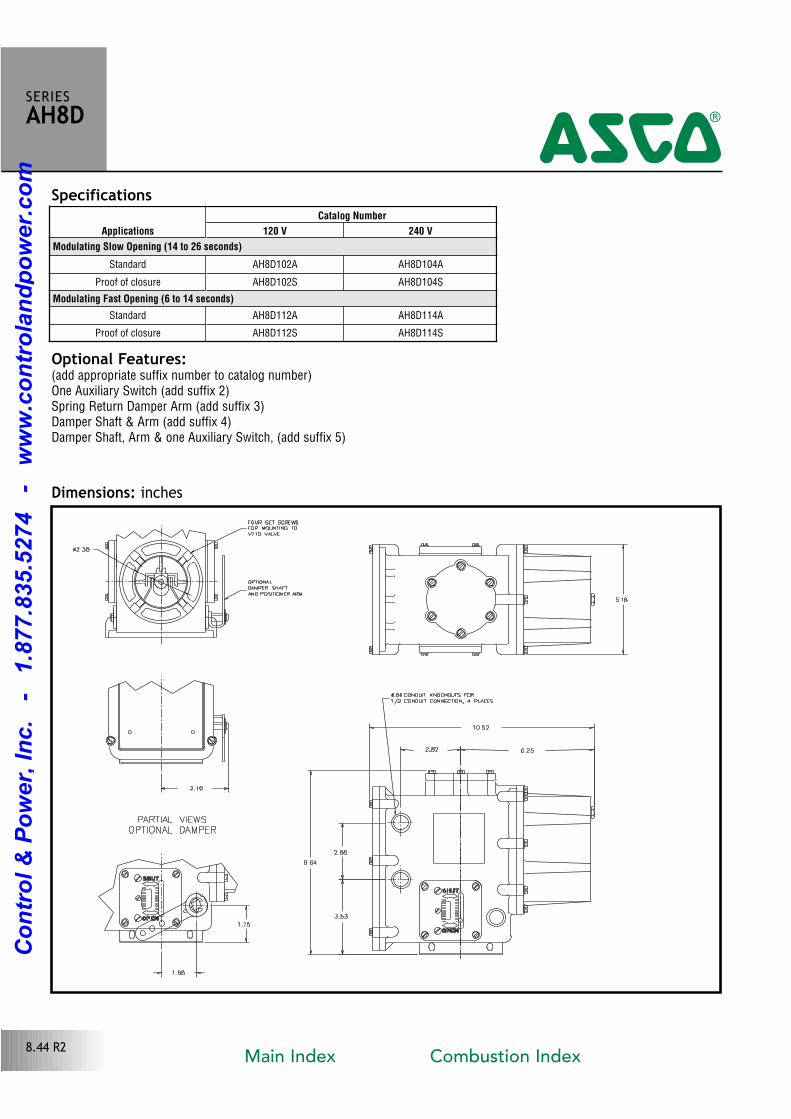
Optional Features:(add appropriate suffix number to catalog number)One Auxiliary Switch (add suffix 2)Spring Return Damper Arm (add suffix 3)Damper Shaft & Arm (add suffix 4)Damper Shaft, Arm & one Auxiliary Switch, (add suffix 5)
Dimensions: inches
SERIESAH8D4
8.44 R2
SpecificationsApplications
Catalog Number
120 V 240 V
Modulating Slow Opening (14 to 26 seconds)
Standard AH8D102A AH8D104A
Proof of closure AH8D102S AH8D104S
Modulating Fast Opening (6 to 14 seconds)
Standard AH8D112A AH8D114A
Proof of closure AH8D112S AH8D114S
Main Index Combustion Index
Co
ntr
ol
& P
ow
er,
In
c.
-
1.8
77.8
35.5
274
-
ww
w.c
on
tro
lan
dp
ow
er.
co
m
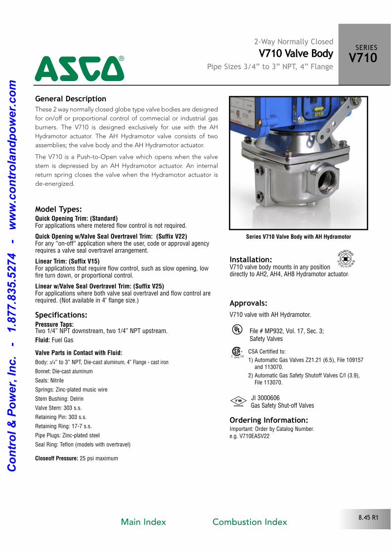
These 2 way normally closed globe type valve bodies are designed
for on/off or proportional control of commecial or industrial gas
burners. The V710 is designed exclusively for use with the AH
Hydramotor actuator. The AH Hydramotor valve consists of two
assemblies; the valve body and the AH Hydramotor actuator.
The V710 is a PushtoOpen valve which opens when the valve
stem is depressed by an AH Hydramotor actuator. An internal
return spring closes the valve when the Hydramotor actuator is
deenergized.
Series V710 Valve Body with AH Hydramotor
Model Types:Quick Opening Trim: (Standard)For applications where metered flow control is not required.
Quick Opening w/Valve Seal Overtravel Trim: (Suffix V22)For any “onoff“ application where the user, code or approval agencyrequires a valve seal overtravel arrangement.
Linear Trim: (Suffix V15)For applications that require flow control, such as slow opening, lowfire turn down, or proportional control.
Linear w/Valve Seal Overtravel Trim: (Suffix V25)For applications where both valve seal overtravel and flow control arerequired. (Not available in 4" flange size.)
Specifications:Pressure Taps: Two 1/4” NPT downstream, two 1/4” NPT upstream.
Fluid: Fuel Gas
Valve Parts in Contact with Fluid:
Body: 3/4” to 3” NPT, Diecast aluminum, 4” Flange cast iron
Bonnet: Diecast aluminum
Seals: Nitrile
Springs: Zincplated music wire
Stem Bushing: Delrin
Valve Stem: 303 s.s.
Retaining Pin: 303 s.s.
Retaining Ring: 177 s.s.
Pipe Plugs: Zincplated steel
Seal Ring: Teflon (models with overtravel)
Closeoff Pressure: 25 psi maximum
2-Way Normally ClosedV710 Valve Body
Pipe Sizes 3/4” to 3” NPT, 4” Flange
SERIESV7104General Description
Installation: V710 valve body mounts in any position directly to AH2, AH4, AH8 Hydramotor actuator.
Approvals:V710 valve with AH Hydramotor.
^
# JI 3000606 Gas Safety Shutoff Valves
Ordering Information:Important: Order by Catalog Number. e.g. V710EASV22
CSA Certified to:
1) Automatic Gas Valves Z21.21 (6.5), File 109157 and 113070.
2) Automatic Gas Safety Shutoff Valves C/I (3.9), File 113070.
File # MP932, Vol. 17, Sec. 3;Safety Valves
8.45 R1Main Index Combustion Index
Co
ntr
ol
& P
ow
er,
In
c.
-
1.8
77.8
35.5
274
-
ww
w.c
on
tro
lan
dp
ow
er.
co
m
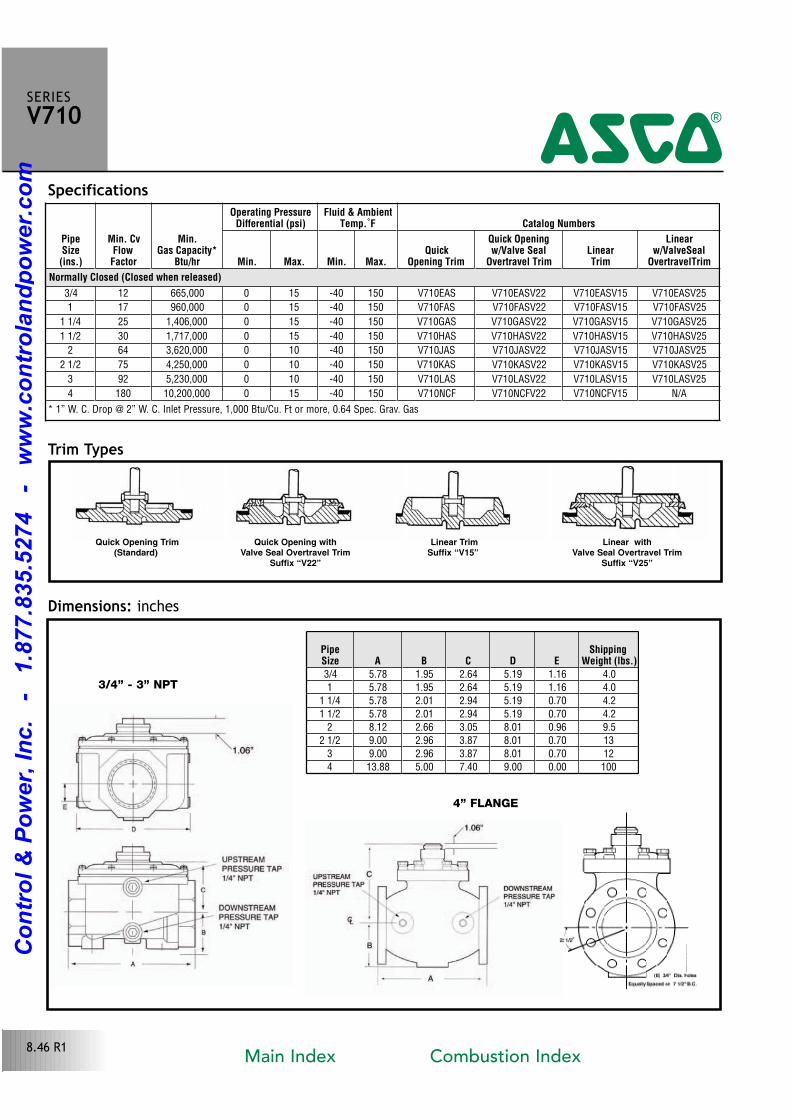
PipeSize(ins.)
Min. CvFlowFactor
Min.Gas Capacity*
Btu/hr
Operating PressureDifferential (psi)
Fluid & AmbientTemp.˚F Catalog Numbers
Min. Max. Min. Max.Quick
Opening Trim
Quick Openingw/Valve Seal
Overtravel TrimLinearTrim
Linearw/ValveSeal
OvertravelTrim
Normally Closed (Closed when released)
3/4 12 665,000 0 15 40 150 V710EAS V710EASV22 V710EASV15 V710EASV25
1 17 960,000 0 15 40 150 V710FAS V710FASV22 V710FASV15 V710FASV25
1 1/4 25 1,406,000 0 15 40 150 V710GAS V710GASV22 V710GASV15 V710GASV25
1 1/2 30 1,717,000 0 15 40 150 V710HAS V710HASV22 V710HASV15 V710HASV25
2 64 3,620,000 0 10 40 150 V710JAS V710JASV22 V710JASV15 V710JASV25
2 1/2 75 4,250,000 0 10 40 150 V710KAS V710KASV22 V710KASV15 V710KASV25
3 92 5,230,000 0 10 40 150 V710LAS V710LASV22 V710LASV15 V710LASV25
4 180 10,200,000 0 15 40 150 V710NCF V710NCFV22 V710NCFV15 N/A
Quick Opening Trim(Standard)
Quick Opening with Valve Seal Overtravel Trim
Suffix “V22”
Linear TrimSuffix “V15”
Linear withValve Seal Overtravel Trim
Suffix “V25”
3/4” - 3” NPT
4” FLANGE
Dimensions: inches
Trim Types
SERIESV7104
* 1” W. C. Drop @ 2” W. C. Inlet Pressure, 1,000 Btu/Cu. Ft or more, 0.64 Spec. Grav. Gas
8.46 R1
PipeSize A B C D E
ShippingWeight (lbs.)
3/4 5.78 1.95 2.64 5.19 1.16 4.0
1 5.78 1.95 2.64 5.19 1.16 4.0
1 1/4 5.78 2.01 2.94 5.19 0.70 4.2
1 1/2 5.78 2.01 2.94 5.19 0.70 4.2
2 8.12 2.66 3.05 8.01 0.96 9.5
2 1/2 9.00 2.96 3.87 8.01 0.70 13
3 9.00 2.96 3.87 8.01 0.70 12
4 13.88 5.00 7.40 9.00 0.00 100
Specifications
Main Index Combustion Index
Co
ntr
ol
& P
ow
er,
In
c.
-
1.8
77.8
35.5
274
-
ww
w.c
on
tro
lan
dp
ow
er.
co
m
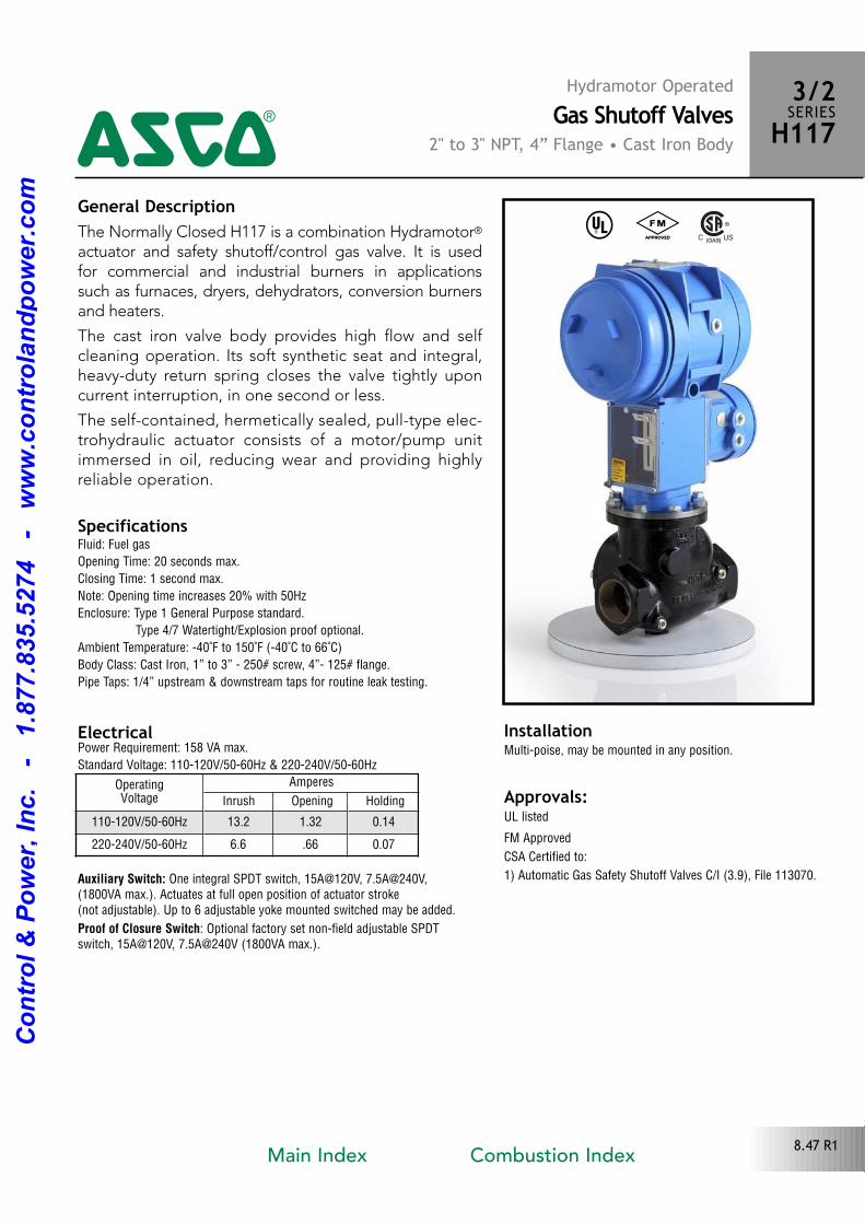
General DescriptionThe Normally Closed H117 is a combination Hydramotor®
actuator and safety shutoff/control gas valve. It is used for commercial and industrial burners in applications such as furnaces, dryers, dehydrators, conversion burnersand heaters.
The cast iron valve body provides high flow and selfcleaning operation. Its soft synthetic seat and integral,heavyduty return spring closes the valve tightly uponcurrent interruption, in one second or less.
The selfcontained, hermetically sealed, pulltype electrohydraulic actuator consists of a motor/pump unitimmersed in oil, reducing wear and providing highlyreliable operation.
Electrical
^ #
Approvals: UL listed
FM Approved
CSA Certified to:
1) Automatic Gas Safety Shutoff Valves C/I (3.9), File 113070.
Hydramotor OperatedGas Shutoff Valves
2" to 3" NPT, 4” Flange • Cast Iron Body
3/2SERIESH1174
8.47 R1
SpecificationsFluid: Fuel gas
Opening Time: 20 seconds max.
Closing Time: 1 second max.
Note: Opening time increases 20% with 50Hz
Enclosure: Type 1 General Purpose standard.
Type 4/7 Watertight/Explosion proof optional.
Ambient Temperature: 40˚F to 150˚F (40˚C to 66˚C)
Body Class: Cast Iron, 1” to 3” 250# screw, 4” 125# flange.
Pipe Taps: 1/4” upstream & downstream taps for routine leak testing.
Power Requirement: 158 VA max.
Standard Voltage: 110120V/5060Hz & 220240V/5060Hz
Auxiliary Switch: One integral SPDT switch, 15A@120V, 7.5A@240V,(1800VA max.). Actuates at full open position of actuator stroke (not adjustable). Up to 6 adjustable yoke mounted switched may be added.
Proof of Closure Switch: Optional factory set nonfield adjustable SPDTswitch, 15A@120V, 7.5A@240V (1800VA max.).
InstallationMultipoise, may be mounted in any position.
OperatingVoltage
Amperes
Inrush Opening Holding
110120V/5060Hz 13.2 1.32 0.14
220240V/5060Hz 6.6 .66 0.07
Main Index Combustion Index
Co
ntr
ol
& P
ow
er,
In
c.
-
1.8
77.8
35.5
274
-
ww
w.c
on
tro
lan
dp
ow
er.
co
m
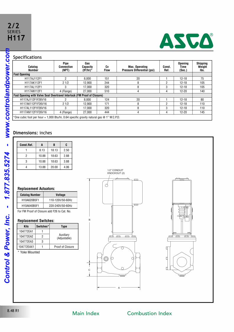
Specifications
B
C
A
OPEN
SHUT
1/2" CONDUIT
KNOCKOUT (2)
Dimensions: inches
2/2SERIESH117
4
8.48 R1
Replacement Actuators:
CatalogNumber
PipeConnection
(NPT)
GasCapacity(ft3/hr)*
CvFlow
Max. Operating Pressure Differential (psi)
Const.Ref.
OpeningTime(Sec.)
ShippingWeight
lbs.
Fast Opening
H117AJ112F1 2 8,000 151 20 1 1218 75
H117AK112F1 2 1/2 12,900 244 8 2 1218 105
H117AL112F1 3 17,000 320 8 3 1218 105
H117AN112F1 4 (Flange) 27,000 510 4 4 1220 140
Fast Opening with Valve Seal Overtravel Interlock (FM Proof of Closure)
H117AJ112F1F26V16 2 8,000 124 20 1 1218 80
H117AK112F1F26V16 2 1/2 12,900 171 8 2 1218 110
H117AL112F1F26V16 3 17,000 320 8 3 1218 110
H117AN112F1F26V16 4 (Flange) 27,000 444 4 4 1220 145
Const.Ref. A B C
1 8.13 18.13 2.50
2 10.88 18.63 2.88
3 10.88 18.63 3.88
4 13.88 20.00 4.06
Catalog Number Voltage
H10A620B5F1 110120V/5060Hz
H10A640B5F1 220240V/5060Hz
Replacement Switches:
Kits Switches* Type
104772EA1 1Auxiliary
(Adjustable)104772EA2 2
104772EA3 3
104772EAX1 1 Proof of Closure
* Yoke Mounted
*One cubic foot per hour = 1,000 Btu/hr, 0.64 specific gravity natural gas @ 1” W.C.P.D.
For FM Proof of Closure add F26 to Cat. No.
Main Index Combustion Index
Co
ntr
ol
& P
ow
er,
In
c.
-
1.8
77.8
35.5
274
-
ww
w.c
on
tro
lan
dp
ow
er.
co
m
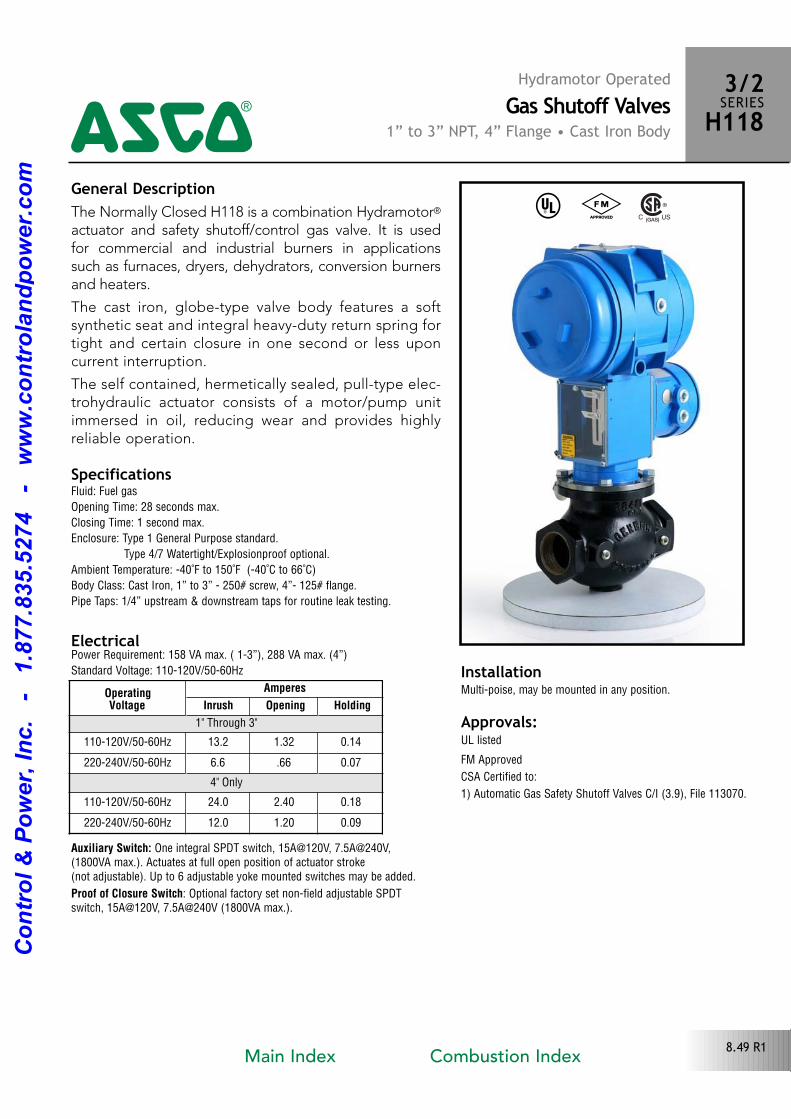
General DescriptionThe Normally Closed H118 is a combination Hydramotor®
actuator and safety shutoff/control gas valve. It is used for commercial and industrial burners in applications such as furnaces, dryers, dehydrators, conversion burnersand heaters.
The cast iron, globetype valve body features a softsynthetic seat and integral heavyduty return spring fortight and certain closure in one second or less uponcurrent interruption.
The self contained, hermetically sealed, pulltype electrohydraulic actuator consists of a motor/pump unitimmersed in oil, reducing wear and provides highly reliable operation.
Electrical
^ #
Approvals: UL listed
FM Approved
CSA Certified to:
1) Automatic Gas Safety Shutoff Valves C/I (3.9), File 113070.
Hydramotor OperatedGas Shutoff Valves
1” to 3” NPT, 4” Flange • Cast Iron Body
3/2SERIESH1184
8.49 R1
SpecificationsFluid: Fuel gas
Opening Time: 28 seconds max.
Closing Time: 1 second max.
Enclosure: Type 1 General Purpose standard.
Type 4/7 Watertight/Explosionproof optional.
Ambient Temperature: 40˚F to 150˚F (40˚C to 66˚C)
Body Class: Cast Iron, 1” to 3” 250# screw, 4” 125# flange.
Pipe Taps: 1/4” upstream & downstream taps for routine leak testing.
Power Requirement: 158 VA max. ( 13”), 288 VA max. (4”)
Standard Voltage: 110120V/5060Hz
Auxiliary Switch: One integral SPDT switch, 15A@120V, 7.5A@240V,(1800VA max.). Actuates at full open position of actuator stroke (not adjustable). Up to 6 adjustable yoke mounted switches may be added.
Proof of Closure Switch: Optional factory set nonfield adjustable SPDTswitch, 15A@120V, 7.5A@240V (1800VA max.).
InstallationMultipoise, may be mounted in any position.Operating
Voltage
Amperes
Inrush Opening Holding
1" Through 3"
110120V/5060Hz 13.2 1.32 0.14
220240V/5060Hz 6.6 .66 0.07
4" Only
110120V/5060Hz 24.0 2.40 0.18
220240V/5060Hz 12.0 1.20 0.09
Main Index Combustion Index
Co
ntr
ol
& P
ow
er,
In
c.
-
1.8
77.8
35.5
274
-
ww
w.c
on
tro
lan
dp
ow
er.
co
m
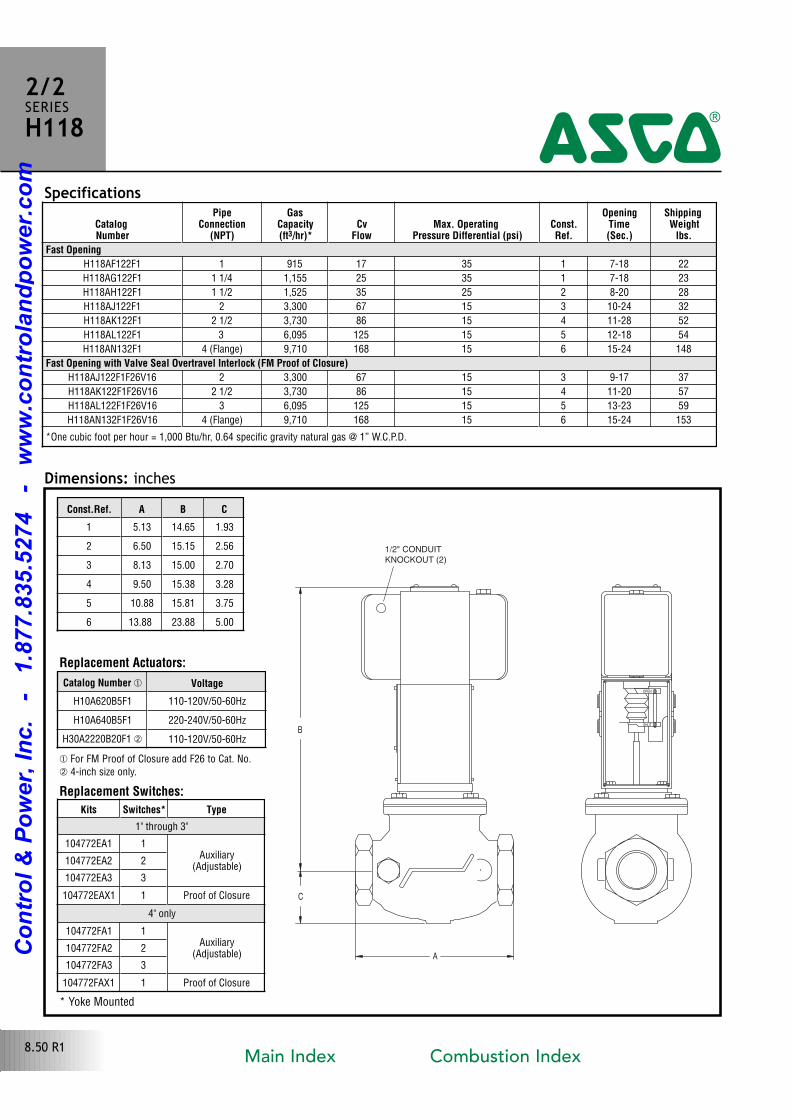
CatalogNumber
PipeConnection
(NPT)
GasCapacity(ft3/hr)*
CvFlow
Max. Operating Pressure Differential (psi)
Const.Ref.
OpeningTime(Sec.)
ShippingWeight
lbs.
Fast Opening
H118AF122F1 1 915 17 35 1 718 22
H118AG122F1 1 1/4 1,155 25 35 1 718 23
H118AH122F1 1 1/2 1,525 35 25 2 820 28
H118AJ122F1 2 3,300 67 15 3 1024 32
H118AK122F1 2 1/2 3,730 86 15 4 1128 52
H118AL122F1 3 6,095 125 15 5 1218 54
H118AN132F1 4 (Flange) 9,710 168 15 6 1524 148
Fast Opening with Valve Seal Overtravel Interlock (FM Proof of Closure)
H118AJ122F1F26V16 2 3,300 67 15 3 917 37
H118AK122F1F26V16 2 1/2 3,730 86 15 4 1120 57
H118AL122F1F26V16 3 6,095 125 15 5 1323 59
H118AN132F1F26V16 4 (Flange) 9,710 168 15 6 1524 153
Specifications
B
C
A
SHUT
OPEN
1/2" CONDUIT
KNOCKOUT (2)
Dimensions: inches
2/2SERIESH118
4
8.50 R1
Replacement Actuators:
*One cubic foot per hour = 1,000 Btu/hr, 0.64 specific gravity natural gas @ 1” W.C.P.D.
� For FM Proof of Closure add F26 to Cat. No. 4inch size only.
Replacement Switches:
Const.Ref. A B C
1 5.13 14.65 1.93
2 6.50 15.15 2.56
3 8.13 15.00 2.70
4 9.50 15.38 3.28
5 10.88 15.81 3.75
6 13.88 23.88 5.00
Catalog Number � Voltage
H10A620B5F1 110120V/5060Hz
H10A640B5F1 220240V/5060Hz
H30A2220B20F1 110120V/5060Hz
Kits Switches* Type
1" through 3"
104772EA1 1Auxiliary
(Adjustable)104772EA2 2
104772EA3 3
104772EAX1 1 Proof of Closure
4" only
104772FA1 1Auxiliary
(Adjustable)104772FA2 2
104772FA3 3
104772FAX1 1 Proof of Closure
* Yoke Mounted
Main Index Combustion Index
Co
ntr
ol
& P
ow
er,
In
c.
-
1.8
77.8
35.5
274
-
ww
w.c
on
tro
lan
dp
ow
er.
co
m
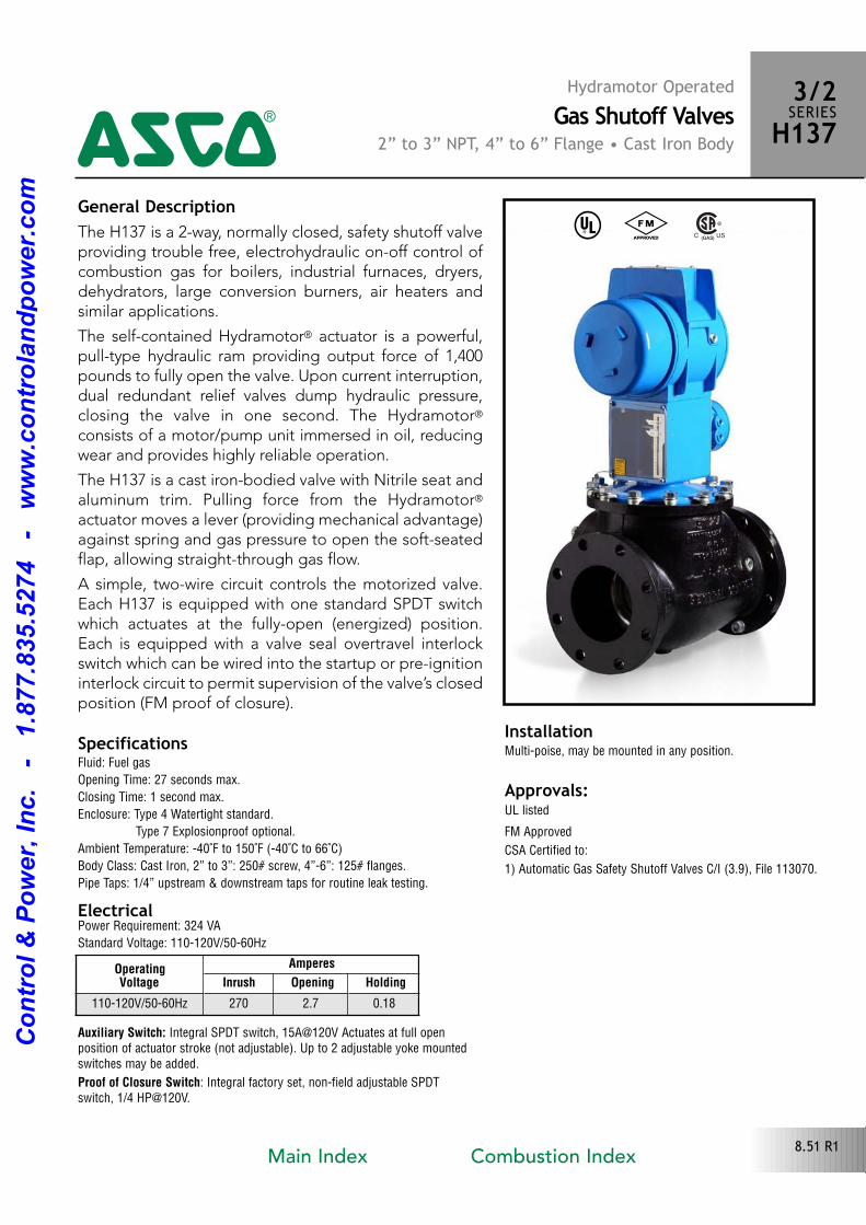
General DescriptionThe H137 is a 2way, normally closed, safety shutoff valveproviding trouble free, electrohydraulic onoff control ofcombustion gas for boilers, industrial furnaces, dryers,dehydrators, large conversion burners, air heaters andsimilar applications.
The selfcontained Hydramotor® actuator is a powerful,pulltype hydraulic ram providing output force of 1,400pounds to fully open the valve. Upon current interruption,dual redundant relief valves dump hydraulic pressure,closing the valve in one second. The Hydramotor®
consists of a motor/pump unit immersed in oil, reducingwear and provides highly reliable operation.
The H137 is a cast ironbodied valve with Nitrile seat andaluminum trim. Pulling force from the Hydramotor®
actuator moves a lever (providing mechanical advantage)against spring and gas pressure to open the softseatedflap, allowing straightthrough gas flow.
A simple, twowire circuit controls the motorized valve.Each H137 is equipped with one standard SPDT switchwhich actuates at the fullyopen (energized) position.Each is equipped with a valve seal overtravel interlockswitch which can be wired into the startup or preignitioninterlock circuit to permit supervision of the valve’s closedposition (FM proof of closure).
Electrical
^ #
Approvals: UL listed
FM Approved
CSA Certified to:
1) Automatic Gas Safety Shutoff Valves C/I (3.9), File 113070.
Hydramotor OperatedGas Shutoff Valves
2” to 3” NPT, 4” to 6” Flange • Cast Iron Body
3/2SERIESH1374
8.51 R1
SpecificationsFluid: Fuel gas
Opening Time: 27 seconds max.
Closing Time: 1 second max.
Enclosure: Type 4 Watertight standard.
Type 7 Explosionproof optional.
Ambient Temperature: 40˚F to 150˚F (40˚C to 66˚C)
Body Class: Cast Iron, 2” to 3”: 250# screw, 4”6”: 125# flanges.
Pipe Taps: 1/4” upstream & downstream taps for routine leak testing.
Power Requirement: 324 VA
Standard Voltage: 110120V/5060Hz
Auxiliary Switch: Integral SPDT switch, 15A@120V Actuates at full openposition of actuator stroke (not adjustable). Up to 2 adjustable yoke mountedswitches may be added.
Proof of Closure Switch: Integral factory set, nonfield adjustable SPDTswitch, 1/4 HP@120V.
InstallationMultipoise, may be mounted in any position.
OperatingVoltage
Amperes
Inrush Opening Holding
110120V/5060Hz 270 2.7 0.18
Main Index Combustion Index
Co
ntr
ol
& P
ow
er,
In
c.
-
1.8
77.8
35.5
274
-
ww
w.c
on
tro
lan
dp
ow
er.
co
m
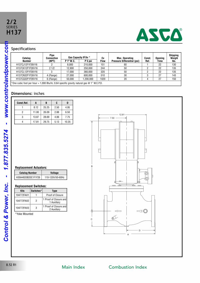
Specifications
D
7.50
B
C
A
12.81
Dimensions: inches
2/2SERIESH137
4
8.52 R1
Replacement Actuators:
Replacement Switches:
CatalogNumber
PipeConnection
(NPT)
Gas Capacity ft3/hr * CvFlow
Max. Operating Pressure Differential (psi)
Const.Ref.
OpeningTime
ShippingWeight
lbs. P 1" W.C. P 5 psi
H137CJ12F1F26V16 2 8,000 210,000 151 60 1 22 130
H137CK12F1F26V16 2 1/2 12,900 250,000 244 50 2 22 135
H137CL12F1F26V16 3 17,000 360,000 320 50 2 22 135
H137CN32F1F26V16 4 (Flange) 27,000 600,000 510 30 3 27 143
H137CQ32F1F26V16 6 (Flange) 50,000 1,200,000 1020 20 4 27 150
Const.Ref. A B C D
1 8.12 25.25 2.50 4.95
2 11.00 26.09 2.88 6.50
3 13.87 28.69 4.06 7.75
4 17.81 29.75 5.13 10.35
Catalog Number Voltage
H30A4820B20C1F1F26 110120V/5060Hz
Kits Switches* Type
104772FAX1 1 Proof of Closure
104772FAX2 21 Proof of Closure and
1 Auxiliary
104772FAX3 31 Proof of Closure and
2 Auxiliary
*Yoke Mounted
*One cubic foot per hour = 1,000 Btu/hr, 0.64 specific gravity natural gas @ 1” W.C.P.D.
Main Index Combustion Index
Co
ntr
ol
& P
ow
er,
In
c.
-
1.8
77.8
35.5
274
-
ww
w.c
on
tro
lan
dp
ow
er.
co
m
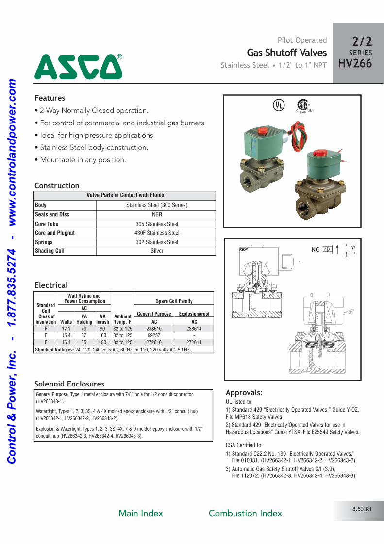
Features• 2Way Normally Closed operation.
• For control of commercial and industrial gas burners.
• Ideal for high pressure applications.
• Stainless Steel body construction.
• Mountable in any position.
Solenoid Enclosures
Construction
General Purpose, Type 1 metal enclosure with 7/8” hole for 1/2 conduit connector
(HV2663431).
Watertight, Types 1, 2, 3, 3S, 4 & 4X molded epoxy enclosure with 1/2” conduit hub
(HV2663421, HV2663422, HV2663432).
Explosion & Watertight, Types 1, 2, 3, 3S, 4X, 7 & 9 molded epoxy enclosure with 1/2”
conduit hub (HV2663423, HV2663424, HV2663433).
Electrical
^
Approvals:UL listed to:
1) Standard 429 “Electrically Operated Valves,” Guide YIOZ,File MP618 Safety Valves.
2) Standard 429 “Electrically Operated Valves for use inHazardous Locations” Guide YTSX, File E25549 Safety Valves.
CSA Certified to:
1) Standard C22.2 No. 139 “Electrically Operated Valves,” File 010381. (HV2663421, HV2663422, HV2663432)
3) Automatic Gas Safety Shutoff Valves C/I (3.9), File 112872. (HV2663423, HV2663424, HV2663433)
Valve Parts in Contact with Fluids
Body Stainless Steel (300 Series)
Seals and Disc NBR
Core Tube 305 Stainless Steel
Core and Plugnut 430F Stainless Steel
Springs 302 Stainless Steel
Shading Coil Silver
Pilot OperatedGas Shutoff Valves
Stainless Steel • 1/2" to 1" NPT4
2/2SERIES
HV266
StandardCoil
Class ofInsulation
Watt Rating and Power Consumption
AmbientTemp.˚F
Spare Coil Family
ACGeneral Purpose Explosionproof
WattsVA
HoldingVA
Inrush AC ACF 17.1 40 90 32 to 125 238610 238614
F 15.4 27 160 32 to 125 99257
F 16.1 35 180 32 to 125 272610 272614
Standard Voltages: 24, 120, 240 volts AC, 60 Hz (or 110, 220 volts AC, 50 Hz).
8.53 R1Main Index Combustion Index
Co
ntr
ol
& P
ow
er,
In
c.
-
1.8
77.8
35.5
274
-
ww
w.c
on
tro
lan
dp
ow
er.
co
m
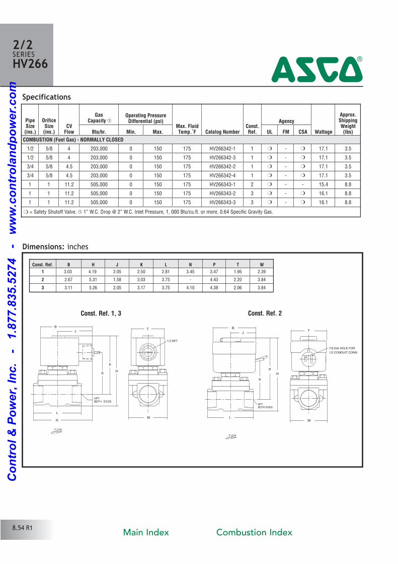
Specifications
Dimensions: inches
Const. Ref. 1, 3
P
H
L
W
K
N
J
BT
1/2 NPT
PipeSize(ins.)
OrificeSize(ins.)
CVFlow
GasCapacity �
Operating PressureDifferential (psi)
Max. FluidTemp.˚F Catalog Number
Const.Ref.
Agency
Wattage
Approx.ShippingWeight(lbs)Btu/hr. Min. Max. UL FM CSA
COMBUSTION (Fuel Gas) - NORMALLY CLOSED
1/2 5/8 4 203,000 0 150 175 HV2663421 1 � � 17.1 3.5
1/2 5/8 4 203,000 0 150 175 HV2663423 1 � � 17.1 3.5
3/4 5/8 4.5 203,000 0 150 175 HV2663422 1 � � 17.1 3.5
3/4 5/8 4.5 203,000 0 150 175 HV2663424 1 � � 17.1 3.5
1 1 11.2 505,000 0 150 175 HV2663431 2 � 15.4 8.8
1 1 11.2 505,000 0 150 175 HV2663432 3 � � 16.1 8.8
1 1 11.2 505,000 0 150 175 HV2663433 3 � � 16.1 8.8
P
H
LW
K
B
JT
7/8 DIA HOLE FOR
1/2 CONDUIT CONN.
NPTBOTH ENDS
Const. Ref. 2
2/2SERIESHV266
4
Const. Ref. B H J K L N P T W
1 3.03 4.19 2.05 2.50 2.81 3.45 3.47 1.95 2.39
2 2.67 5.31 1.58 3.03 3.75 4.43 2.20 3.84
3 3.11 5.26 2.05 3.17 3.75 4.10 4.38 2.06 3.84
� = Safety Shutoff Valve. � 1” W.C. Drop @ 2” W.C. Inlet Pressure, 1, 000 Btu/cu.ft. or more, 0.64 Specific Gravity Gas.
8.54 R1Main Index Combustion Index
Co
ntr
ol
& P
ow
er,
In
c.
-
1.8
77.8
35.5
274
-
ww
w.c
on
tro
lan
dp
ow
er.
co
m
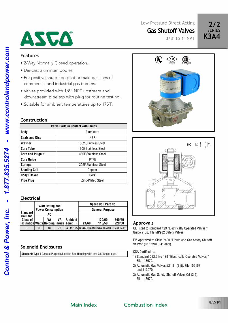
Features• 2Way Normally Closed operation.
• Diecast aluminum bodies.
• For positive shutoff on pilot or main gas lines of
commercial and industrial gas burners.
• Valves provided with 1/8” NPT upstream and
downstream pipe tap with plug for routine testing.
• Suitable for ambient temperatures up to 175˚F.
Solenoid Enclosures
Construction
Standard: Type 1 General Purpose Junction Box Housing with two 7/8” knockouts.
Electrical
^ #
Valve Parts in Contact with Fluids
Body Aluminum
Seals and Disc NBR
Washer 302 Stainless Steel
Core Tube 305 Stainless Steel
Core and Plugnut 430F Stainless Steel
Core Guide PTFE
Springs 302F Stainless Steel
Shading Coil Copper
Body Gasket Cork
Pipe Plug ZincPlated Steel
ApprovalsUL listed to standard 429 “Electrically Operated Valves,”Guide YIOZ, File MP932 Safety Valves.
FM Approved to Class 7400 “Liquid and Gas Safety ShutoffValves” (3/8” thru 3/4” only).
CSA Certified to:
1) Standard C22.2 No 139 “Electrically Operated Valves,” File 113070.
2) Automatic Gas Valves Z21.21 (6.5), File 109157 and 113070.
3) Automatic Gas Safety Shutoff Valves C/I (3.9),File 113070.
NC
2/2SERIESK3A44
Low Pressure Direct ActingGas Shutoff Valves
3/8" to 1" NPT
StandardCoil and Class of
Insulation
Watt Rating andPower Consumption
AmbientTemp.˚F
Spare Coil Part No.
General Purpose
AC
24/60120/60110/50
240/60220/50Watts
VAHolding
VAInrush
F 10 18 77 40 to 175 CS4AF01A18 CS4AF02A18 CS4AF04A18
8.55 R1Main Index Combustion Index
Co
ntr
ol
& P
ow
er,
In
c.
-
1.8
77.8
35.5
274
-
ww
w.c
on
tro
lan
dp
ow
er.
co
m
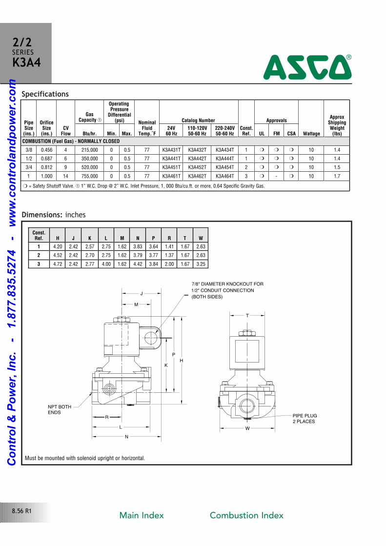
Specifications
Dimensions: inches
PipeSize(ins.)
OrificeSize(ins.)
CVFlow
GasCapacity �
OperatingPressure
Differential(psi) Nominal
FluidTemp.˚F
Catalog Number
Const.Ref.
Approvals
Wattage
ApproxShippingWeight(lbs)Btu/hr. Min. Max.
24V60 Hz
110-120V50-60 Hz
220-240V50-60 Hz UL FM CSA
COMBUSTION (Fuel Gas) - NORMALLY CLOSED
3/8 0.456 4 215,000 0 0.5 77 K3A431T K3A432T K3A434T 1 � � � 10 1.4
1/2 0.687 6 350,000 0 0.5 77 K3A441T K3A442T K3A444T 1 � � � 10 1.4
3/4 0.812 9 520,000 0 0.5 77 K3A451T K3A452T K3A454T 2 � � � 10 1.5
1 1.000 14 755,000 0 0.5 77 K3A461T K3A462T K3A464T 3 � � 10 1.7
Const.Ref. H J K L M N P R T W
1 4.20 2.42 2.57 2.75 1.62 3.83 3.64 1.41 1.67 2.63
2 4.52 2.42 2.70 2.75 1.62 3.79 3.77 1.37 1.67 2.63
3 4.72 2.42 2.77 4.00 1.62 4.42 3.84 2.00 1.67 3.25
NPT BOTH
ENDS
2 PLACES
PIPE PLUG
(BOTH SIDES)
1/2" CONDUIT CONNECTION
7/8" DIAMETER KNOCKOUT FOR
K
P
N
H
R
L W
J
M
T
2/2SERIESK3A4
4
� = Safety Shutoff Valve. � 1” W.C. Drop @ 2” W.C. Inlet Pressure, 1, 000 Btu/cu.ft. or more, 0.64 Specific Gravity Gas.
Must be mounted with solenoid upright or horizontal.
8.56 R1Main Index Combustion Index
Co
ntr
ol
& P
ow
er,
In
c.
-
1.8
77.8
35.5
274
-
ww
w.c
on
tro
lan
dp
ow
er.
co
m
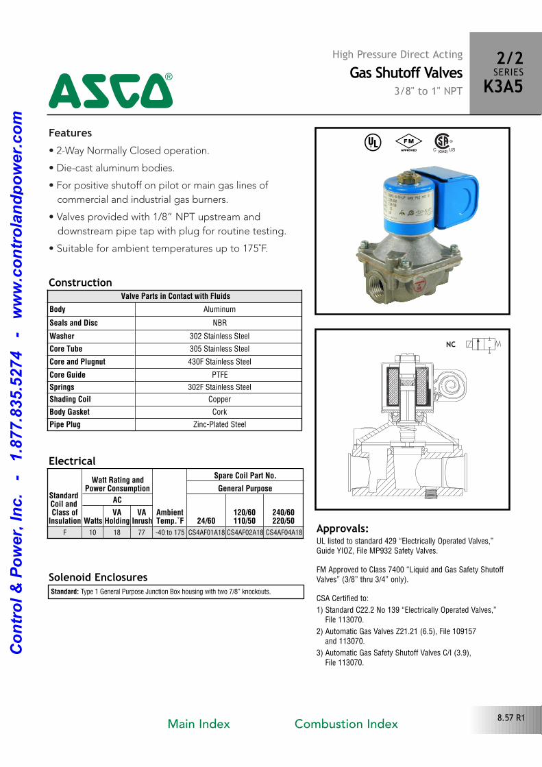
Features• 2Way Normally Closed operation.
• Diecast aluminum bodies.
• For positive shutoff on pilot or main gas lines of
commercial and industrial gas burners.
• Valves provided with 1/8” NPT upstream and
downstream pipe tap with plug for routine testing.
• Suitable for ambient temperatures up to 175˚F.
Solenoid Enclosures
Construction
Standard: Type 1 General Purpose Junction Box housing with two 7/8” knockouts.
Electrical
Approvals:UL listed to standard 429 “Electrically Operated Valves,”Guide YIOZ, File MP932 Safety Valves.
FM Approved to Class 7400 “Liquid and Gas Safety ShutoffValves” (3/8” thru 3/4” only).
CSA Certified to:
1) Standard C22.2 No 139 “Electrically Operated Valves,” File 113070.
2) Automatic Gas Valves Z21.21 (6.5), File 109157 and 113070.
3) Automatic Gas Safety Shutoff Valves C/I (3.9),File 113070.
Valve Parts in Contact with Fluids
Body Aluminum
Seals and Disc NBR
Washer 302 Stainless Steel
Core Tube 305 Stainless Steel
Core and Plugnut 430F Stainless Steel
Core Guide PTFE
Springs 302F Stainless Steel
Shading Coil Copper
Body Gasket Cork
Pipe Plug ZincPlated Steel
StandardCoil and Class of
Insulation
Watt Rating andPower Consumption
AmbientTemp.˚F
Spare Coil Part No.
General Purpose
AC
24/60120/60110/50
240/60220/50Watts
VAHolding
VAInrush
F 10 18 77 40 to 175 CS4AF01A18 CS4AF02A18 CS4AF04A18
NC
High Pressure Direct ActingGas Shutoff Valves
i3/8" to 1" NPT
2/2SERIESK3A54
^ #
8.57 R1Main Index Combustion Index
Co
ntr
ol
& P
ow
er,
In
c.
-
1.8
77.8
35.5
274
-
ww
w.c
on
tro
lan
dp
ow
er.
co
m
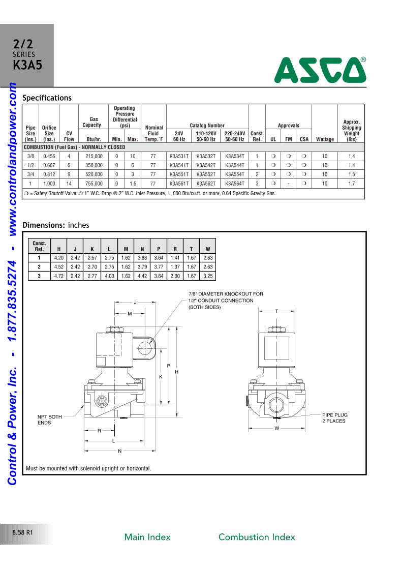
PipeSize(ins.)
OrificeSize(ins.)
CVFlow
GasCapacity
OperatingPressure
Differential(psi)
FluidTemp.˚F
Catalog Number
Const.Ref.
Approvals
Wattage
Approx.ShippingWeight(lbs)Btu/hr. Min. Max.
24V60 Hz
110-120V50-60 Hz
220-240V50-60 Hz UL FM CSA
COMBUSTION (Fuel Gas) - NORMALLY CLOSED
3/8 0.456 4 215,000 0 10 77 K3A531T K3A532T K3A534T 1 � � � 10 1.4
1/2 0.687 6 350,000 0 6 77 K3A541T K3A542T K3A544T 1 � � � 10 1.4
3/4 0.812 9 520,000 0 3 77 K3A551T K3A552T K3A554T 2 � � � 10 1.5
1 1.000 14 755,000 0 1.5 77 K3A561T K3A562T K3A564T 3 � � 10 1.7
Nominal
Specifications
Dimensions: inchesConst.Ref. H J K L M N P R T W
1 4.20 2.42 2.57 2.75 1.62 3.83 3.64 1.41 1.67 2.63
2 4.52 2.42 2.70 2.75 1.62 3.79 3.77 1.37 1.67 2.63
3 4.72 2.42 2.77 4.00 1.62 4.42 3.84 2.00 1.67 3.25
NPT BOTH
ENDS 2 PLACES
PIPE PLUG
(BOTH SIDES)
1/2" CONDUIT CONNECTION
7/8" DIAMETER KNOCKOUT FOR
K
P
N
H
R
L
W
J
MT
2/2SERIESK3A5
4
� = Safety Shutoff Valve. � 1” W.C. Drop @ 2” W.C. Inlet Pressure, 1, 000 Btu/cu.ft. or more, 0.64 Specific Gravity Gas.
Must be mounted with solenoid upright or horizontal.
8.58 R1Main Index Combustion Index
Co
ntr
ol
& P
ow
er,
In
c.
-
1.8
77.8
35.5
274
-
ww
w.c
on
tro
lan
dp
ow
er.
co
m
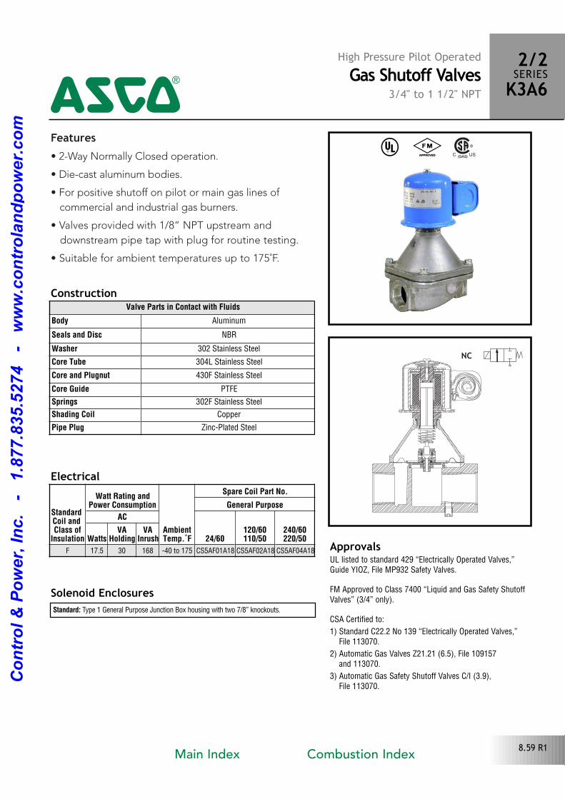
Features• 2Way Normally Closed operation.
• Diecast aluminum bodies.
• For positive shutoff on pilot or main gas lines of
commercial and industrial gas burners.
• Valves provided with 1/8” NPT upstream and
downstream pipe tap with plug for routine testing.
• Suitable for ambient temperatures up to 175˚F.
Solenoid Enclosures
Construction
Standard: Type 1 General Purpose Junction Box housing with two 7/8” knockouts.
Electrical
ApprovalsUL listed to standard 429 “Electrically Operated Valves,”Guide YIOZ, File MP932 Safety Valves.
FM Approved to Class 7400 “Liquid and Gas Safety ShutoffValves” (3/4” only).
CSA Certified to:
1) Standard C22.2 No 139 “Electrically Operated Valves,” File 113070.
2) Automatic Gas Valves Z21.21 (6.5), File 109157 and 113070.
3) Automatic Gas Safety Shutoff Valves C/I (3.9),File 113070.
Valve Parts in Contact with Fluids
Body Aluminum
Seals and Disc NBR
Washer 302 Stainless Steel
Core Tube 304L Stainless Steel
Core and Plugnut 430F Stainless Steel
Core Guide PTFE
Springs 302F Stainless Steel
Shading Coil Copper
Pipe Plug ZincPlated Steel
StandardCoil and Class of
Insulation
Watt Rating andPower Consumption
AmbientTemp.˚F
Spare Coil Part No.
General Purpose
AC
24/60120/60110/50
240/60220/50Watts
VAHolding
VAInrush
F 17.5 30 168 40 to 175 CS5AF01A18 CS5AF02A18 CS5AF04A18
NC
High Pressure Pilot OperatedGas Shutoff Valves
3/4" to 1 1/2" NPT
^ #
4
2/2SERIESK3A6
8.59 R1Main Index Combustion Index
Co
ntr
ol
& P
ow
er,
In
c.
-
1.8
77.8
35.5
274
-
ww
w.c
on
tro
lan
dp
ow
er.
co
m
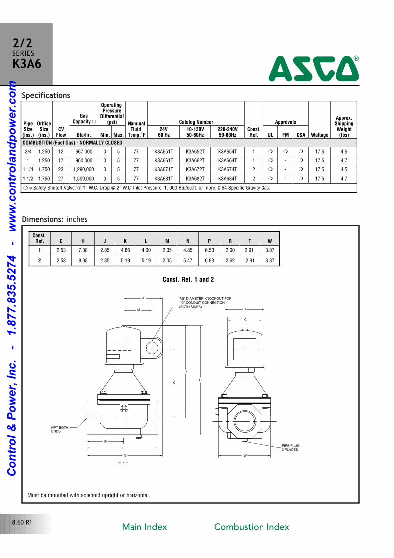
Specifications
Dimensions: inches
PipeSize(ins.)
OrificeSize(ins.)
CVFlow
GasCapacity �
OperatingPressure
Differential(psi) Nominal
FluidTemp.˚F
Catalog Number
Const.Ref.
Approvals
Wattage
Approx.ShippingWeight(lbs)Btu/hr. Min. Max.
24V60 Hz
10-120V50-60Hz
220-240V50-60Hz UL FM CSA
COMBUSTION (Fuel Gas) - NORMALLY CLOSED
3/4 1.250 12 667,000 0 5 77 K3A651T K3A652T K3A654T 1 � � � 17.5 4.5
1 1.250 17 960,000 0 5 77 K3A661T K3A662T K3A664T 1 � � 17.5 4.7
1 1/4 1.750 23 1,290,000 0 5 77 K3A671T K3A672T K3A674T 2 � � 17.5 4.5
1 1/2 1.750 27 1,509,000 0 5 77 K3A681T K3A682T K3A684T 2 � � 17.5 4.7
Const. Ref. 1 and 2
K
P
H
W
C
TM
J 7/8" DIAMETER KNOCKOUT FOR
(BOTH SIDES)
1/2" CONDUIT CONNECTION
NPT BOTH ENDS
PIPE PLUG2 PLACES
R
L
N
FLOW
Const.Ref. C H J K L M N P R T W
1 2.53 7.38 2.85 4.86 4.00 2.05 4.85 6.50 2.00 2.91 3.87
2 2.53 8.08 2.85 5.19 5.19 2.05 5.47 6.83 2.62 2.91 3.87
2/2SERIESK3A6
4
� = Safety Shutoff Valve. � 1” W.C. Drop @ 2” W.C. Inlet Pressure, 1, 000 Btu/cu.ft. or more, 0.64 Specific Gravity Gas.
Must be mounted with solenoid upright or horizontal.
8.60 R1Main Index Combustion Index
Co
ntr
ol
& P
ow
er,
In
c.
-
1.8
77.8
35.5
274
-
ww
w.c
on
tro
lan
dp
ow
er.
co
m
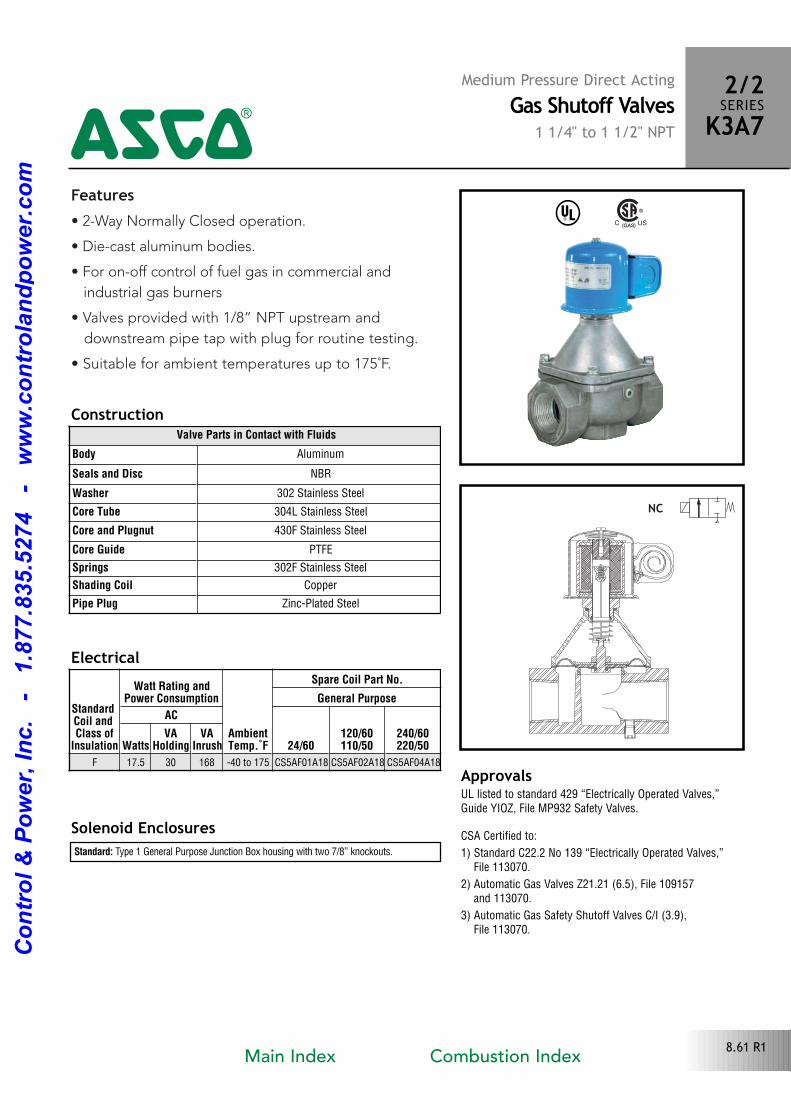
Features• 2Way Normally Closed operation.
• Diecast aluminum bodies.
• For onoff control of fuel gas in commercial and
industrial gas burners
• Valves provided with 1/8” NPT upstream and
downstream pipe tap with plug for routine testing.
• Suitable for ambient temperatures up to 175˚F.
Solenoid Enclosures
Construction
Standard: Type 1 General Purpose Junction Box housing with two 7/8” knockouts.
Electrical
^
ApprovalsUL listed to standard 429 “Electrically Operated Valves,”Guide YIOZ, File MP932 Safety Valves.
CSA Certified to:
1) Standard C22.2 No 139 “Electrically Operated Valves,” File 113070.
2) Automatic Gas Valves Z21.21 (6.5), File 109157 and 113070.
3) Automatic Gas Safety Shutoff Valves C/I (3.9),File 113070.
Valve Parts in Contact with Fluids
Body Aluminum
Seals and Disc NBR
Washer 302 Stainless Steel
Core Tube 304L Stainless Steel
Core and Plugnut 430F Stainless Steel
Core Guide PTFE
Springs 302F Stainless Steel
Shading Coil Copper
Pipe Plug ZincPlated Steel
NC
Medium Pressure Direct ActingGas Shutoff Valves
1 1/4" to 1 1/2" NPT
2/2SERIESK3A74
StandardCoil and Class of
Insulation
Watt Rating andPower Consumption
AmbientTemp.˚F
Spare Coil Part No.
General Purpose
AC
24/60120/60110/50
240/60220/50Watts
VAHolding
VAInrush
F 17.5 30 168 40 to 175 CS5AF01A18 CS5AF02A18 CS5AF04A18
8.61 R1Main Index Combustion Index
Co
ntr
ol
& P
ow
er,
In
c.
-
1.8
77.8
35.5
274
-
ww
w.c
on
tro
lan
dp
ow
er.
co
m
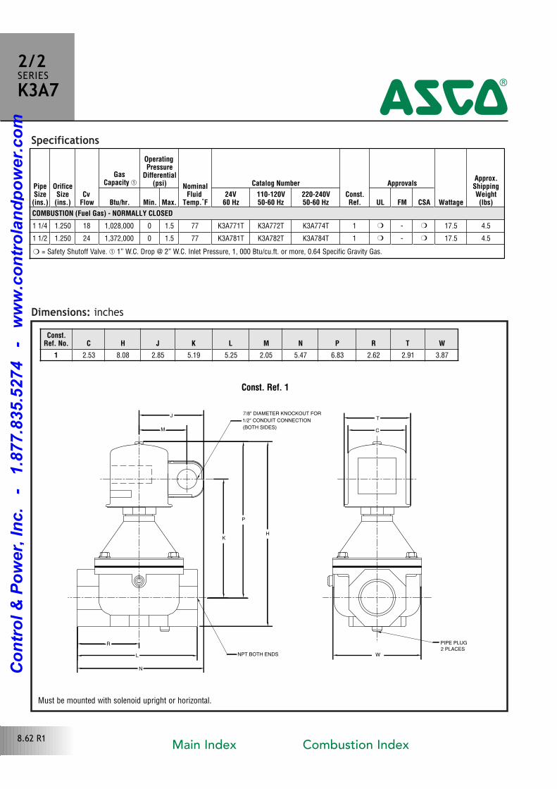
Specifications
Dimensions: inches
PipeSize(ins.)
OrificeSize(ins.)
CvFlow
GasCapacity �
OperatingPressure
Differential(psi) Nominal
FluidTemp.˚F
Catalog Number
Const.Ref.
Approvals
Wattage
Approx.ShippingWeight(lbs)Btu/hr. Min. Max.
24V60 Hz
110-120V50-60 Hz
220-240V50-60 Hz UL FM CSA
COMBUSTION (Fuel Gas) - NORMALLY CLOSED
1 1/4 1.250 18 1,028,000 0 1.5 77 K3A771T K3A772T K3A774T 1 � � 17.5 4.5
1 1/2 1.250 24 1,372,000 0 1.5 77 K3A781T K3A782T K3A784T 1 � � 17.5 4.5
Const. Ref. 1
7/8" DIAMETER KNOCKOUT FOR
(BOTH SIDES)
1/2" CONDUIT CONNECTION
PIPE PLUG
2 PLACESNPT BOTH ENDS
K
P
H
W
J
C
T
R
L
N
M
Const.Ref. No. C H J K L M N P R T W
1 2.53 8.08 2.85 5.19 5.25 2.05 5.47 6.83 2.62 2.91 3.87
2/2SERIESK3A7
4
� = Safety Shutoff Valve. � 1” W.C. Drop @ 2” W.C. Inlet Pressure, 1, 000 Btu/cu.ft. or more, 0.64 Specific Gravity Gas.
Must be mounted with solenoid upright or horizontal.
8.62 R1Main Index Combustion Index
Co
ntr
ol
& P
ow
er,
In
c.
-
1.8
77.8
35.5
274
-
ww
w.c
on
tro
lan
dp
ow
er.
co
m
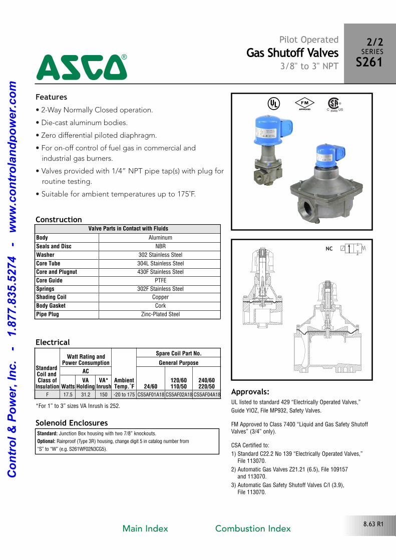
Features• 2Way Normally Closed operation.
• Diecast aluminum bodies.
• Zero differential piloted diaphragm.
• For onoff control of fuel gas in commercial and
industrial gas burners.
• Valves provided with 1/4” NPT pipe tap(s) with plug for
routine testing.
• Suitable for ambient temperatures up to 175˚F.
Solenoid Enclosures
Construction
Standard: Junction Box housing with two 7/8” knockouts.
Optional: Rainproof (Type 3R) housing, change digit 5 in catalog number from
“S” to “W” (e.g. S261WF02N3CG5).
Electrical
NC
Approvals:UL listed to standard 429 “Electrically Operated Valves,”
Guide YIOZ, File MP932, Safety Valves.
FM Approved to Class 7400 “Liquid and Gas Safety ShutoffValves” (3/4” only).
CSA Certified to:
1) Standard C22.2 No 139 “Electrically Operated Valves,” File 113070.
2) Automatic Gas Valves Z21.21 (6.5), File 109157 and 113070.
3) Automatic Gas Safety Shutoff Valves C/I (3.9),File 113070.
Valve Parts in Contact with Fluids
Body Aluminum
Seals and Disc NBR
Washer 302 Stainless Steel
Core Tube 304L Stainless Steel
Core and Plugnut 430F Stainless Steel
Core Guide PTFE
Springs 302F Stainless Steel
Shading Coil Copper
Body Gasket Cork
Pipe Plug ZincPlated Steel
Pilot OperatedGas Shutoff Valves
3/8" to 3" NPT
2/2SERIESS261
4^ #
StandardCoil and Class of
Insulation
Watt Rating andPower Consumption
AmbientTemp.˚F
Spare Coil Part No.
General Purpose
AC
24/60120/60110/50
240/60220/50Watts
VAHolding
VA*Inrush
F 17.5 31.2 150 20 to 175 CS5AF01A18 CS5AF02A18 CS5AF04A18
8.63 R1
*For 1” to 3” sizes VA Inrush is 252.
Main Index Combustion Index
Co
ntr
ol
& P
ow
er,
In
c.
-
1.8
77.8
35.5
274
-
ww
w.c
on
tro
lan
dp
ow
er.
co
m
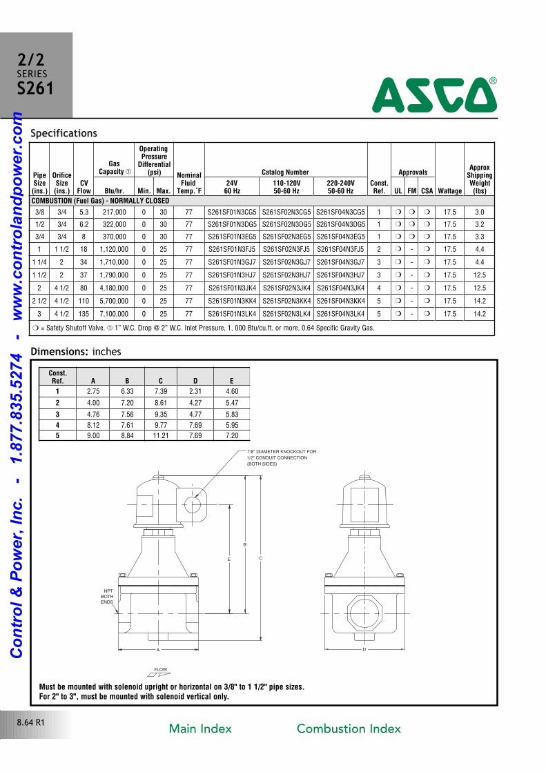
Specifications
FLOW
B
E C
A
NPT
BOTH
ENDS
7/8" DIAMETER KNOCKOUT FOR
1/2" CONDUIT CONNECTION
(BOTH SIDES)
D
Dimensions: inches
PipeSize(ins.)
OrificeSize(ins.)
CVFlow
GasCapacity �
OperatingPressure
Differential(psi) Nominal
FluidTemp.˚F
Catalog Number
Const.Ref.
Approvals
Wattage
ApproxShippingWeight(lbs)Btu/hr. Min. Max.
24V60 Hz
110-120V50-60 Hz
220-240V50-60 Hz UL FM CSA
COMBUSTION (Fuel Gas) - NORMALLY CLOSED
3/8 3/4 5.3 217,000 0 30 77 S261SF01N3CG5 S261SF02N3CG5 S261SF04N3CG5 1 � � � 17.5 3.0
1/2 3/4 6.2 322,000 0 30 77 S261SF01N3DG5 S261SF02N3DG5 S261SF04N3DG5 1 � � � 17.5 3.2
3/4 3/4 8 370,000 0 30 77 S261SF01N3EG5 S261SF02N3EG5 S261SF04N3EG5 1 � � � 17.5 3.3
1 1 1/2 18 1,120,000 0 25 77 S261SF01N3FJ5 S261SF02N3FJ5 S261SF04N3FJ5 2 � � 17.5 4.4
1 1/4 2 34 1,710,000 0 25 77 S261SF01N3GJ7 S261SF02N3GJ7 S261SF04N3GJ7 3 � � 17.5 4.4
1 1/2 2 37 1,790,000 0 25 77 S261SF01N3HJ7 S261SF02N3HJ7 S261SF04N3HJ7 3 � � 17.5 12.5
2 4 1/2 80 4,180,000 0 25 77 S261SF01N3JK4 S261SF02N3JK4 S261SF04N3JK4 4 � � 17.5 12.5
2 1/2 4 1/2 110 5,700,000 0 25 77 S261SF01N3KK4 S261SF02N3KK4 S261SF04N3KK4 5 � � 17.5 14.2
3 4 1/2 135 7,100,000 0 25 77 S261SF01N3LK4 S261SF02N3LK4 S261SF04N3LK4 5 � � 17.5 14.2
2/2SERIESS261
4
Const.Ref. A B C D E
1 2.75 6.33 7.39 2.31 4.60
2 4.00 7.20 8.61 4.27 5.47
3 4.76 7.56 9.35 4.77 5.83
4 8.12 7.61 9.77 7.69 5.95
5 9.00 8.84 11.21 7.69 7.20
8.64 R1
� = Safety Shutoff Valve. � 1” W.C. Drop @ 2” W.C. Inlet Pressure, 1, 000 Btu/cu.ft. or more, 0.64 Specific Gravity Gas.
Must be mounted with solenoid upright or horizontal on 3/8" to 1 1/2" pipe sizes. For 2" to 3", must be mounted with solenoid vertical only.
Main Index Combustion Index
Co
ntr
ol
& P
ow
er,
In
c.
-
1.8
77.8
35.5
274
-
ww
w.c
on
tro
lan
dp
ow
er.
co
m
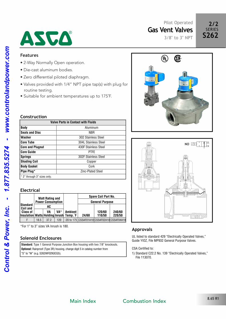
Features• 2Way Normally Open operation.
• Diecast aluminum bodies.
• Zero differential piloted diaphragm.
• Valves provided with 1/4” NPT pipe tap(s) with plug for
routine testing.
• Suitable for ambient temperatures up to 175˚F.
Solenoid Enclosures
Construction
Standard: Type 1 General Purpose Junction Box housing with two 7/8” knockouts.
Optional: Rainproof (Type 3R) housing, change digit 5 in catalog number from
“S” to “W” (e.g. S262WF02N3CG5).
Electrical
^ %
ApprovalsUL listed to standard 429 “Electrically Operated Valves,”Guide YIOZ, File MP932 General Purpose Valves.
CSA Certified to:
1) Standard C22.2 No. 139 “Electrically Operated Valves,” File 113070.
Valve Parts in Contact with Fluids
Body Aluminum
Seals and Disc NBR
Washer 302 Stainless Steel
Core Tube 304L Stainless Steel
Core and Plugnut 430F Stainless Steel
Core Guide PTFE
Springs 302F Stainless Steel
Shading Coil Copper
Body Gasket Cork
Pipe Plug* ZincPlated Steel
* 2” through 3” sizes only.
StandardCoil and Class of
Insulation
Watt Rating andPower Consumption
AmbientTemp.˚F
Spare Coil Part No.
General Purpose
AC
24/60120/60110/50
240/60220/50Watts
VAHolding
VA*Inrush
F 18.5 37.2 120 20 to 175 CS5AF01A18 CS5AF02A18 CS5AF04A18
Pilot OperatedGas Vent Valves
3/8" to 3" NPT
2/2SERIESS262
4
8.65 R1
*For 1” to 3” sizes VA Inrush is 180.
Main Index Combustion Index
Co
ntr
ol
& P
ow
er,
In
c.
-
1.8
77.8
35.5
274
-
ww
w.c
on
tro
lan
dp
ow
er.
co
m
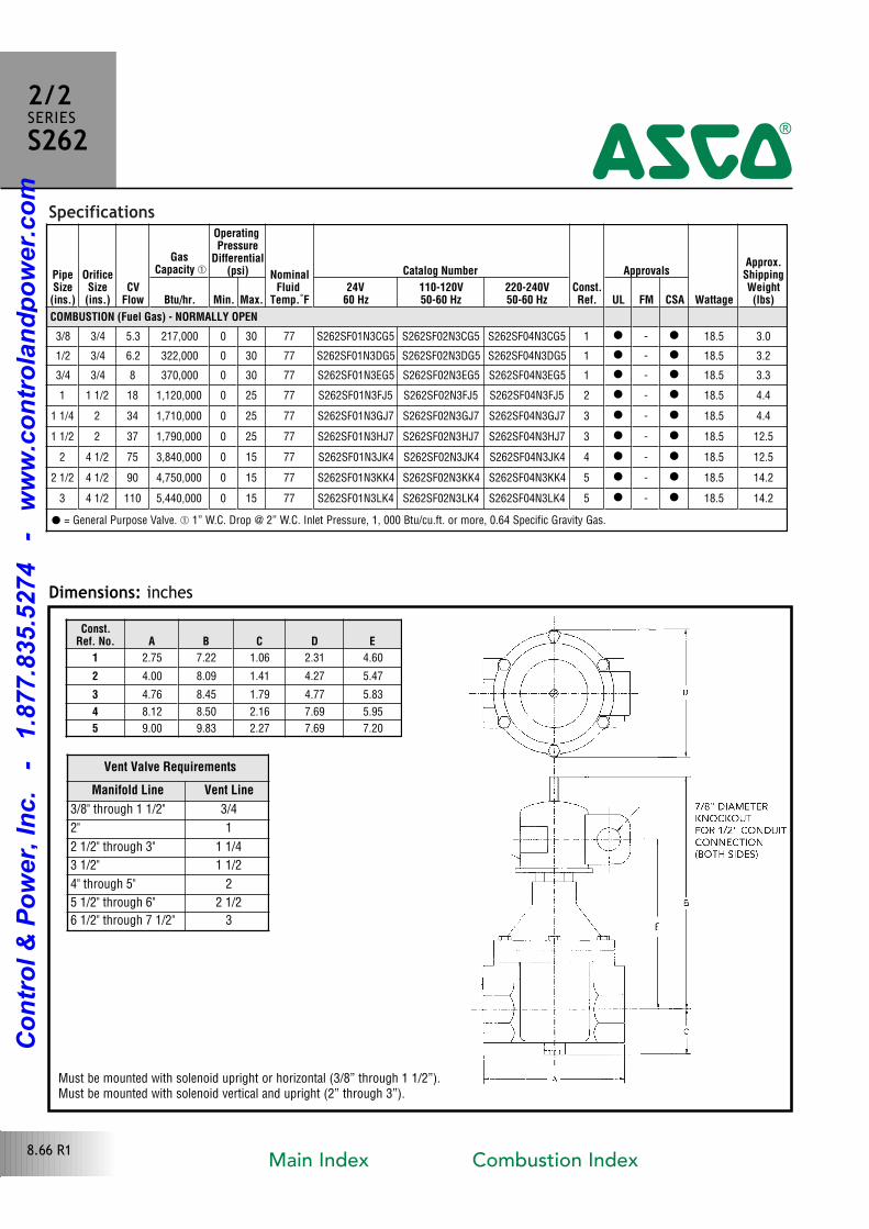
Specifications
Dimensions: inches
PipeSize(ins.)
OrificeSize(ins.)
CVFlow
GasCapacity �
OperatingPressure
Differential(psi) Nominal
FluidTemp.˚F
Catalog Number
Const.Ref.
Approvals
Wattage
Approx.ShippingWeight(lbs)Btu/hr. Min. Max.
24V60 Hz
110-120V50-60 Hz
220-240V50-60 Hz UL FM CSA
COMBUSTION (Fuel Gas) - NORMALLY OPEN
3/8 3/4 5.3 217,000 0 30 77 S262SF01N3CG5 S262SF02N3CG5 S262SF04N3CG5 1 � � 18.5 3.0
1/2 3/4 6.2 322,000 0 30 77 S262SF01N3DG5 S262SF02N3DG5 S262SF04N3DG5 1 � � 18.5 3.2
3/4 3/4 8 370,000 0 30 77 S262SF01N3EG5 S262SF02N3EG5 S262SF04N3EG5 1 � � 18.5 3.3
1 1 1/2 18 1,120,000 0 25 77 S262SF01N3FJ5 S262SF02N3FJ5 S262SF04N3FJ5 2 � � 18.5 4.4
1 1/4 2 34 1,710,000 0 25 77 S262SF01N3GJ7 S262SF02N3GJ7 S262SF04N3GJ7 3 � � 18.5 4.4
1 1/2 2 37 1,790,000 0 25 77 S262SF01N3HJ7 S262SF02N3HJ7 S262SF04N3HJ7 3 � � 18.5 12.5
2 4 1/2 75 3,840,000 0 15 77 S262SF01N3JK4 S262SF02N3JK4 S262SF04N3JK4 4 � � 18.5 12.5
2 1/2 4 1/2 90 4,750,000 0 15 77 S262SF01N3KK4 S262SF02N3KK4 S262SF04N3KK4 5 � � 18.5 14.2
3 4 1/2 110 5,440,000 0 15 77 S262SF01N3LK4 S262SF02N3LK4 S262SF04N3LK4 5 � � 18.5 14.2
Const.Ref. No. A B C D E
1 2.75 7.22 1.06 2.31 4.60
2 4.00 8.09 1.41 4.27 5.47
3 4.76 8.45 1.79 4.77 5.83
4 8.12 8.50 2.16 7.69 5.95
5 9.00 9.83 2.27 7.69 7.20
Vent Valve Requirements
Manifold Line Vent Line
3/8" through 1 1/2" 3/4
2" 1
2 1/2" through 3" 1 1/4
3 1/2" 1 1/2
4" through 5" 2
5 1/2" through 6" 2 1/2
6 1/2" through 7 1/2" 3
2/2SERIESS262
4
� = General Purpose Valve. � 1” W.C. Drop @ 2” W.C. Inlet Pressure, 1, 000 Btu/cu.ft. or more, 0.64 Specific Gravity Gas.
Must be mounted with solenoid upright or horizontal (3/8” through 1 1/2”).Must be mounted with solenoid vertical and upright (2” through 3”).
8.66 R1Main Index Combustion Index
Co
ntr
ol
& P
ow
er,
In
c.
-
1.8
77.8
35.5
274
-
ww
w.c
on
tro
lan
dp
ow
er.
co
m
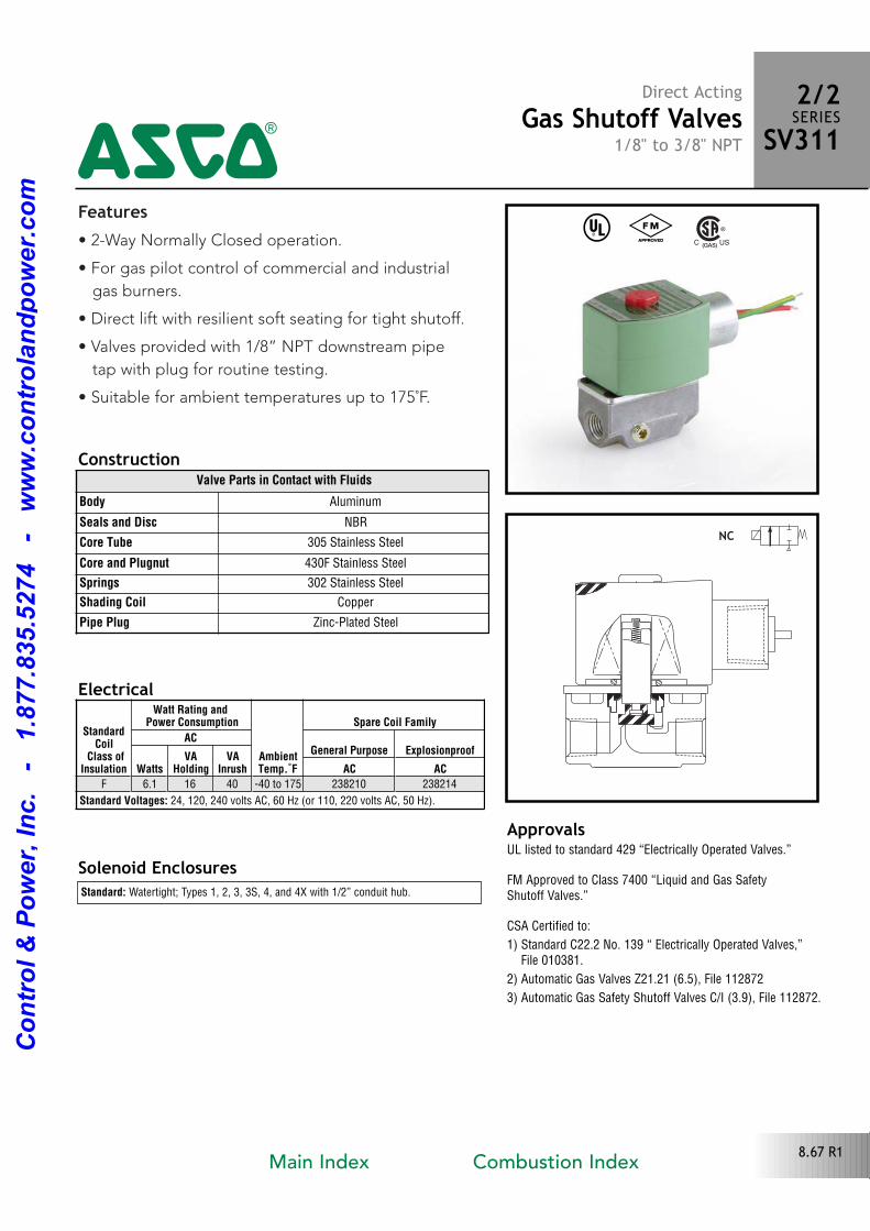
Features• 2Way Normally Closed operation.
• For gas pilot control of commercial and industrial
gas burners.
• Direct lift with resilient soft seating for tight shutoff.
• Valves provided with 1/8” NPT downstream pipe
tap with plug for routine testing.
• Suitable for ambient temperatures up to 175˚F.
Solenoid Enclosures
Construction
Standard: Watertight; Types 1, 2, 3, 3S, 4, and 4X with 1/2” conduit hub.
Electrical
ApprovalsUL listed to standard 429 “Electrically Operated Valves.”
FM Approved to Class 7400 “Liquid and Gas Safety Shutoff Valves.”
CSA Certified to:
1) Standard C22.2 No. 139 “ Electrically Operated Valves,”File 010381.
2) Automatic Gas Valves Z21.21 (6.5), File 112872
3) Automatic Gas Safety Shutoff Valves C/I (3.9), File 112872.
^ #
Valve Parts in Contact with Fluids
Body Aluminum
Seals and Disc NBR
Core Tube 305 Stainless Steel
Core and Plugnut 430F Stainless Steel
Springs 302 Stainless Steel
Shading Coil Copper
Pipe Plug ZincPlated Steel
NC
Direct ActingGas Shutoff Valves
1/8" to 3/8" NPT
2/2SERIESSV311
4
StandardCoil
Class ofInsulation
Watt Rating and Power Consumption
AmbientTemp.˚F
Spare Coil Family
ACGeneral Purpose Explosionproof
WattsVA
HoldingVA
Inrush AC ACF 6.1 16 40 40 to 175 238210 238214
Standard Voltages: 24, 120, 240 volts AC, 60 Hz (or 110, 220 volts AC, 50 Hz).
8.67 R1Main Index Combustion Index
Co
ntr
ol
& P
ow
er,
In
c.
-
1.8
77.8
35.5
274
-
ww
w.c
on
tro
lan
dp
ow
er.
co
m
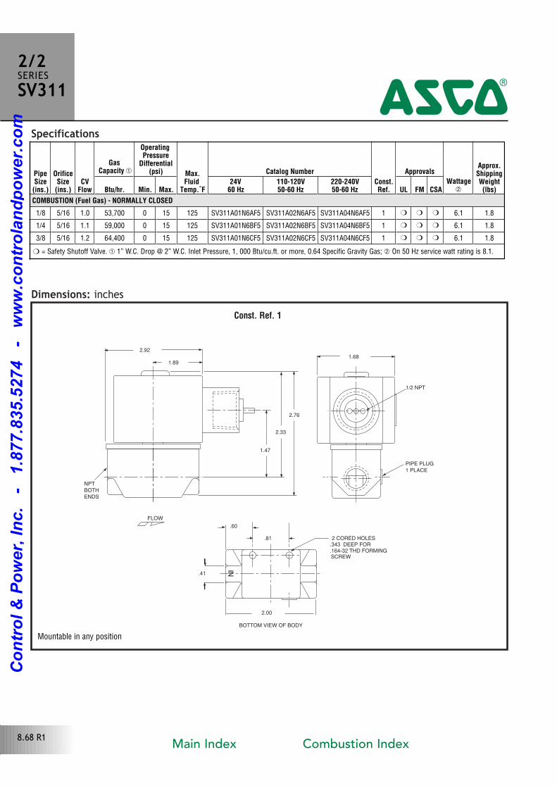
Specifications
Dimensions: inchesConst. Ref. 1
BOTTOM VIEW OF BODY
FLOW
NI
.16432 THD FORMING
.343 DEEP FOR2 CORED HOLES
SCREW
PIPE PLUG
1 PLACE
1/2 NPT
NPT
BOTH
ENDS
2.92
1.89
1.47
2.33
2.76
1.68
.60
.81
.41
2.00
PipeSize(ins.)
OrificeSize(ins.)
CVFlow
GasCapacity �
OperatingPressure
Differential(psi) Max.
FluidTemp.˚F
Catalog Number
Const.Ref.
Approvals
Wattage
Approx.ShippingWeight(lbs)Btu/hr. Min. Max.
24V60 Hz
110-120V50-60 Hz
220-240V50-60 Hz UL FM CSA
COMBUSTION (Fuel Gas) - NORMALLY CLOSED
1/8 5/16 1.0 53,700 0 15 125 SV311A01N6AF5 SV311A02N6AF5 SV311A04N6AF5 1 � � � 6.1 1.8
1/4 5/16 1.1 59,000 0 15 125 SV311A01N6BF5 SV311A02N6BF5 SV311A04N6BF5 1 � � � 6.1 1.8
3/8 5/16 1.2 64,400 0 15 125 SV311A01N6CF5 SV311A02N6CF5 SV311A04N6CF5 1 � � � 6.1 1.8
2/2SERIESSV311
4
� = Safety Shutoff Valve. � 1” W.C. Drop @ 2” W.C. Inlet Pressure, 1, 000 Btu/cu.ft. or more, 0.64 Specific Gravity Gas; On 50 Hz service watt rating is 8.1.
8.68 R1
Mountable in any position
Main Index Combustion Index
Co
ntr
ol
& P
ow
er,
In
c.
-
1.8
77.8
35.5
274
-
ww
w.c
on
tro
lan
dp
ow
er.
co
m
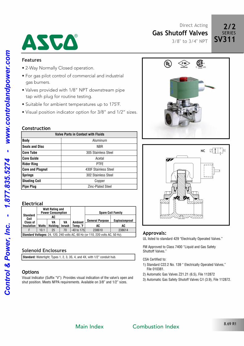
Features• 2Way Normally Closed operation.
• For gas pilot control of commercial and industrial
gas burners.
• Valves provided with 1/8” NPT downstream pipe
tap with plug for routine testing.
• Suitable for ambient temperatures up to 175˚F.
• Visual position indicator option for 3/8” and 1/2” sizes.
Solenoid Enclosures
Construction
Standard: Watertight; Types 1, 2, 3, 3S, 4, and 4X, with 1/2” conduit hub.
Electrical
Valve Parts in Contact with Fluids
Body Aluminum
Seals and Disc NBR
Core Tube 305 Stainless Steel
Core Guide Acetal
Rider Ring PTFE
Core and Plugnut 430F Stainless Steel
Springs 302 Stainless Steel
Shading Coil Copper
Pipe Plug ZincPlated Steel
Approvals:UL listed to standard 429 “Electrically Operated Valves.”
FM Approved to Class 7400 “Liquid and Gas Safety Shuttoff Valves.”
CSA Certified to:
1) Standard C22.2 No. 139 “ Electrically Operated Valves,”File 010381.
2) Automatic Gas Valves Z21.21 (6.5), File 112872
3) Automatic Gas Safety Shutoff Valves C/I (3.9), File 112872.
NC
Direct ActingGas Shutoff Valves
3/8" to 3/4" NPT
2/2SERIESSV311
4^ #
StandardCoil
Class ofInsulation
Watt Rating and Power Consumption
AmbientTemp.˚F
Spare Coil Family
ACGeneral Purpose Explosionproof
WattsVA
HoldingVA
Inrush AC ACF 10.1 25 70 40 to 175 238610 238614
Standard Voltages: 24, 120, 240 volts AC, 60 Hz (or 110, 220 volts AC, 50 Hz).
OptionsVisual Indicator (Suffix “V”): Provides visual indication of the valve’s open andshut position. Meets NFPA requirements. Available on 3/8” and 1/2” sizes.
8.69 R1Main Index Combustion Index
Co
ntr
ol
& P
ow
er,
In
c.
-
1.8
77.8
35.5
274
-
ww
w.c
on
tro
lan
dp
ow
er.
co
m
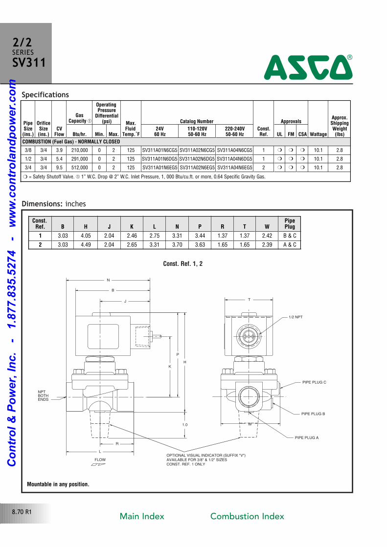
Specifications
Dimensions: inches
Const. Ref. 1, 2
FLOW
ENDS
NPTBOTH
R
H
B
N
J
L
K
P
1/2 NPT
PIPE PLUG C
PIPE PLUG B
W
T
PIPE PLUG A
1.0
OPTIONAL VISUAL INDICATOR (SUFFIX "V")AVAILABLE FOR 3/8" & 1/2" SIZESCONST. REF. 1 ONLY
Const.Ref. B H J K L N P R T W
PipePlug
1 3.03 4.05 2.04 2.46 2.75 3.31 3.44 1.37 1.37 2.42 B & C
2 3.03 4.49 2.04 2.65 3.31 3.70 3.63 1.65 1.65 2.39 A & C
PipeSize(ins.)
OrificeSize(ins.)
CVFlow
GasCapacity �
OperatingPressure
Differential(psi) Max.
FluidTemp.˚F
Catalog Number
Const.Ref.
Approvals
Wattage
Approx.ShippingWeight(lbs)Btu/hr. Min. Max.
24V60 Hz
110-120V50-60 Hz
220-240V50-60 Hz UL FM CSA
COMBUSTION (Fuel Gas) - NORMALLY CLOSED
3/8 3/4 3.9 210,000 0 2 125 SV311A01N6CG5 SV311A02N6CG5 SV311A04N6CG5 1 � � � 10.1 2.8
1/2 3/4 5.4 291,000 0 2 125 SV311A01N6DG5 SV311A02N6DG5 SV311A04N6DG5 1 � � � 10.1 2.8
3/4 3/4 9.5 512,000 0 2 125 SV311A01N6EG5 SV311A02N6EG5 SV311A04N6EG5 2 � � � 10.1 2.8
2/2SERIESSV311
4
� = Safety Shutoff Valve. � 1” W.C. Drop @ 2” W.C. Inlet Pressure, 1, 000 Btu/cu.ft. or more, 0.64 Specific Gravity Gas.
8.70 R1
Mountable in any position.
Main Index Combustion Index
Co
ntr
ol
& P
ow
er,
In
c.
-
1.8
77.8
35.5
274
-
ww
w.c
on
tro
lan
dp
ow
er.
co
m
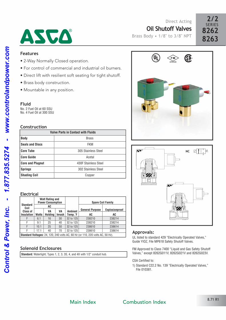
Direct ActingOil Shutoff Valves
Brass Body • 1/8" to 3/8" NPT
^ # %Features• 2Way Normally Closed operation.
• For control of commercial and industrial oil burners.
• Direct lift with resilient soft seating for tight shutoff.
• Brass body construction.
• Mountable in any position.
Solenoid Enclosures
Electrical
Construction
Standard: Watertight; Types 1, 2, 3, 3S, 4, and 4X with 1/2” conduit hub.
Approvals:UL listed to standard 429 “Electrically Operated Valves,”Guide YIOZ, File MP618 Safety Shutoff Valves.
FM Approved to Class 7400 “Liquid and Gas Safety ShutoffValves,” except 8262G011V, 8262G021V and 8262G023V.
CSA Certified to:
1) Standard C22.2 No. 139 “Electrically Operated Valves,” File 010381.
2/2SERIES826282634
8.71 R1
Valve Parts in Contact with Fluids
Body Brass
Seals and Discs FKM
Core Tube 305 Stainless Steel
Core Guide Acetal
Core and Plugnut 430F Stainless Steel
Springs 302 Stainless Steel
Shading Coil Copper
StandardCoil
Class ofInsulation
Watt Rating and Power Consumption
AmbientTemp.˚F
Spare Coil Family
ACGeneral Purpose Explosionproof
WattsVA
HoldingVA
Inrush AC ACF 6.1 16 30 32 to 125 238210 238214
F 9.1 25 40 32 to 125 238210 238214
F 10.1 25 50 32 to 125 238610 238614
F 17.1 40 70 32 to 125 238610 238614
Standard Voltages: 24, 120, 240 volts AC, 60 Hz (or 110, 220 volts AC, 50 Hz).
FluidNo. 2 Fuel Oil at 60 SSU No. 4 Fuel Oil at 300 SSU
Main Index Combustion Index
Co
ntr
ol
& P
ow
er,
In
c.
-
1.8
77.8
35.5
274
-
ww
w.c
on
tro
lan
dp
ow
er.
co
m
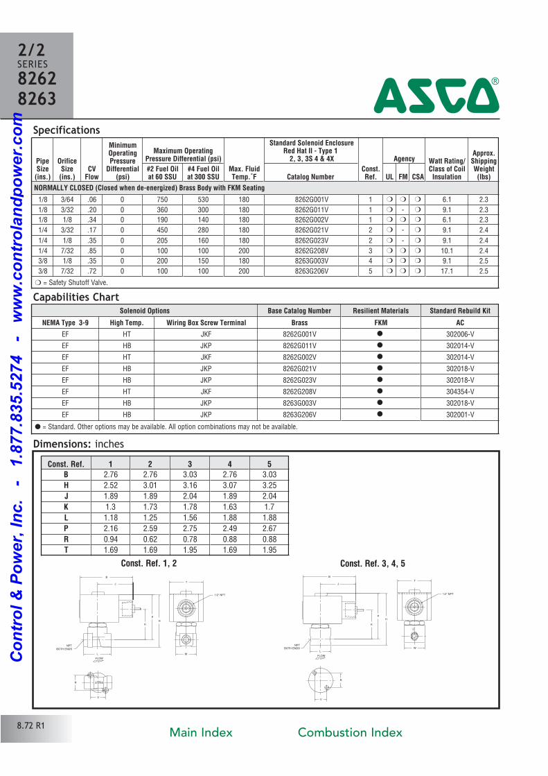
PipeSize(ins.)
OrificeSize(ins.)
CVFlow
MinimumOperatingPressure
Differential(psi)
Maximum OperatingPressure Differential (psi)
Max. FluidTemp.˚F
Standard Solenoid EnclosureRed Hat II - Type 1
2, 3, 3S 4 & 4X
Const.Ref.
Agency Watt Rating/Class of CoilInsulation
Approx.ShippingWeight(lbs)
#2 Fuel Oilat 60 SSU
#4 Fuel Oilat 300 SSU Catalog Number UL FM CSA
NORMALLY CLOSED (Closed when de-energized) Brass Body with FKM Seating
1/8 3/64 .06 0 750 530 180 8262G001V 1 � � � 6.1 2.3
1/8 3/32 .20 0 360 300 180 8262G011V 1 � � 9.1 2.3
1/8 1/8 .34 0 190 140 180 8262G002V 1 � � � 6.1 2.3
1/4 3/32 .17 0 450 280 180 8262G021V 2 � � 9.1 2.4
1/4 1/8 .35 0 205 160 180 8262G023V 2 � � 9.1 2.4
1/4 7/32 .85 0 100 100 200 8262G208V 3 � � � 10.1 2.4
3/8 1/8 .35 0 200 150 180 8263G003V 4 � � � 9.1 2.5
3/8 7/32 .72 0 100 100 200 8263G206V 5 � � � 17.1 2.5
Dimensions: inches
NPT
BOTH ENDS
1/2" NPT
T
B
J
R
V
K
P
H
L W
FLOW
Const. Ref. 1, 2
Specifications
Const. Ref. 3, 4, 5
NPTBOTH ENDS
1/2" NPT
T
L
K
PH
W
B
J
V
R
FLOW
2
2/2SERIES82628263 4
� = Safety Shutoff Valve.
Capabilities Chart
Const. Ref. 1 2 3 4 5B 2.76 2.76 3.03 2.76 3.03
H 2.52 3.01 3.16 3.07 3.25
J 1.89 1.89 2.04 1.89 2.04
K 1.3 1.73 1.78 1.63 1.7
L 1.18 1.25 1.56 1.88 1.88
P 2.16 2.59 2.75 2.49 2.67
R 0.94 0.62 0.78 0.88 0.88
T 1.69 1.69 1.95 1.69 1.95
Solenoid Options Base Catalog Number Resilient Materials Standard Rebuild Kit
NEMA Type 3-9 High Temp. Wiring Box Screw Terminal Brass FKM AC
EF HT JKF 8262G001V � 302006V
EF HB JKP 8262G011V � 302014V
EF HT JKF 8262G002V � 302014V
EF HB JKP 8262G021V � 302018V
EF HB JKP 8262G023V � 302018V
EF HT JKF 8262G208V � 304354V
EF HB JKP 8263G003V � 302018V
EF HB JKP 8263G206V � 302001V
� = Standard. Other options may be available. All option combinations may not be available.
8.72 R1Main Index Combustion Index
Co
ntr
ol
& P
ow
er,
In
c.
-
1.8
77.8
35.5
274
-
ww
w.c
on
tro
lan
dp
ow
er.
co
m
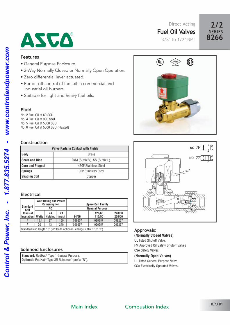
Features• General Purpose Enclosure.
• 2Way Normally Closed or Normally Open Operation.
• Zero differential lever actuated.
• For onoff control of fuel oil in commercial and industrial oil burners.
• Suitable for light and heavy fuel oils.
Solenoid Enclosures
Construction
Electrical
^ # %
Approvals: (Normally Closed Valves)UL listed Shutoff Valve.
FM Approved Oil Safety Shutoff Valves
CSA Safety Valves
(Normally Open Valves)UL listed General Purpose Valve.
CSA Electrically Operated Valves
NC
NO
Direct ActingFuel Oil Valves3/8" to 1/2" NPT
8.73 R1
FluidNo. 2 Fuel Oil at 60 SSUNo. 4 Fuel Oil at 300 SSUNo. 5 Fuel Oil at 5000 SSUNo. 6 Fuel Oil at 5000 SSU (Heated)
Standard: RedHat ® Type 1 General Purpose.Optional: RedHat ® Type 3R Rainproof (prefix “R”).
Valve Parts in Contact with Fluids
Body Brass
Seals and Disc FKM (Suffix V), SS (Suffix L)
Core and Plugnut 430F Stainless Steel
Springs 302 Stainless Steel
Shading Coil Copper
StandardCoil
Class ofInsulation
Watt Rating and PowerComsumption Spare Coil Family
AC General Purpose
WattsVA
HoldingVA
Inrush 24/60120/60110/50
240/60220/50
F 15.4 27 160 099257 099257 099257
F 20 43 240 099257 099257 099257
Standard lead length 18" (72" leads optional change suffix "D" to "K")
4
2/2SERIES8266
Main Index Combustion Index
Co
ntr
ol
& P
ow
er,
In
c.
-
1.8
77.8
35.5
274
-
ww
w.c
on
tro
lan
dp
ow
er.
co
m
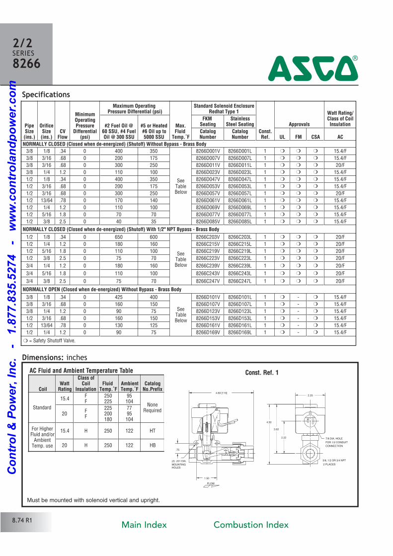
Specifications
Dimensions: inchesConst. Ref. 1
2/2SERIES8266
4
Must be mounted with solenoid vertical and upright.
8.74 R1
PipeSize(ins.)
OrificeSize(ins.)
CVFlow
MinimumOperatingPressure
Differential(psi)
Maximum Operating Pressure Differential (psi)
Max.Fluid
Temp.˚F
Standard Solenoid EnclosureRedhat Type 1
Const.Ref.
Approvals
Watt Rating/Class of CoilInsulation#2 Fuel Oil @
60 SSU, #4 FuelOil @ 300 SSU
#5 or Heated#6 Oil up to5000 SSU
FKM
SeatingStainless
Steel Seating
CatalogNumber
CatalogNumber UL FM CSA AC
NORMALLY CLOSED (Closed when de-energized) (Shutoff) Without Bypass - Brass Body
3/8 1/8 .34 0 400 350
SeeTableBelow
8266D001V 8266D001L 1 � � � 15.4/F
3/8 3/16 .68 0 200 175 8266D007V 8266D007L 1 � � � 15.4/F
3/8 3/16 .68 0 300 250 8266D011V 8266D011L 1 � � � 20/F
3/8 1/4 1.2 0 110 100 8266D023V 8266D023L 1 � � � 15.4/F
1/2 1/8 .34 0 400 350 8266D047V 8266D047L 1 � � � 15.4/F
1/2 3/16 .68 0 200 175 8266D053V 8266D053L 1 � � � 15.4/F
1/2 3/16 .68 0 300 250 8266D057V 8266D057L 1 � � � 20/F
1/2 13/64 .78 0 170 140 8266D061V 8266D061L 1 � � � 15.4/F
1/2 1/4 1.2 0 110 100 8266D069V 8266D069L 1 � � � 15.4/F
1/2 5/16 1.8 0 70 70 8266D077V 8266D077L 1 � � � 15.4/F
1/2 3/8 2.5 0 40 35 8266D085V 8266D085L 1 � � � 15.4/F
NORMALLY CLOSED (Closed when de-energized) (Shutoff) With 1/2" NPT Bypass - Brass Body
1/2 1/8 .34 0 650 600
SeeTableBelow
8266C203V 8266C203L 1 � � � 20/F
1/2 1/4 1.2 0 180 160 8266C215V 8266C215L 1 � � � 20/F
1/2 5/16 1.8 0 110 100 8266C219V 8266C219L 1 � � � 20/F
1/2 3/8 2.5 0 75 70 8266C223V 8266C223L 1 � � � 20/F
3/4 1/4 1.2 0 180 160 8266C239V 8266C239L 1 � � � 20/F
3/4 5/16 1.8 0 110 100 8266C243V 8266C243L 1 � � � 20/F
3/4 3/8 2.5 0 75 70 8266C247V 8266C247L 1 � � � 20/F
NORMALLY OPEN (Closed when de-energized) Without Bypass - Brass Body
3/8 1/8 .34 0 425 400
SeeTableBelow
8266D101V 8266D101L 1 � � 15.4/F
3/8 3/16 .68 0 160 150 8266D107V 8266D107L 1 � � 15.4/F
3/8 1/4 1.2 0 90 75 8266D123V 8266D123L 1 � � 15.4/F
1/2 3/16 .68 0 160 150 8266D153V 8266D153L 1 � � 15.4/F
1/2 13/64 .78 0 130 125 8266D161V 8266D161L 1 � � 15.4/F
1/2 1/4 1.2 0 90 75 8266D169V 8266D169L 1 � � 15.4/F
� = Safety Shutoff Valve.
CoilWatt
Rating
Class ofCoil
InsulationFluid
Temp.˚FAmbientTemp.˚F
CatalogNo.Prefix
Standard
15.4FF
250225
95104
NoneRequired
20FF
225200180
7795
104
For HigherFluid and/or
AmbientTemp. use
15.4 H 250 122 HT
20 H 250 122 HB
AC Fluid and Ambient Temperature Table
4.50
3.62
2.20
2.22
(2) .201 DIA.
MOUNTINGHOLES
.75
1.50
4.69 [119]
FLOW
7/8 DIA. HOLE
3/8, 1/2 OR 3/4 NPT
2 PLACES
FOR 1/2 CONDUIT
CONNECTION
Main Index Combustion Index
Co
ntr
ol
& P
ow
er,
In
c.
-
1.8
77.8
35.5
274
-
ww
w.c
on
tro
lan
dp
ow
er.
co
m
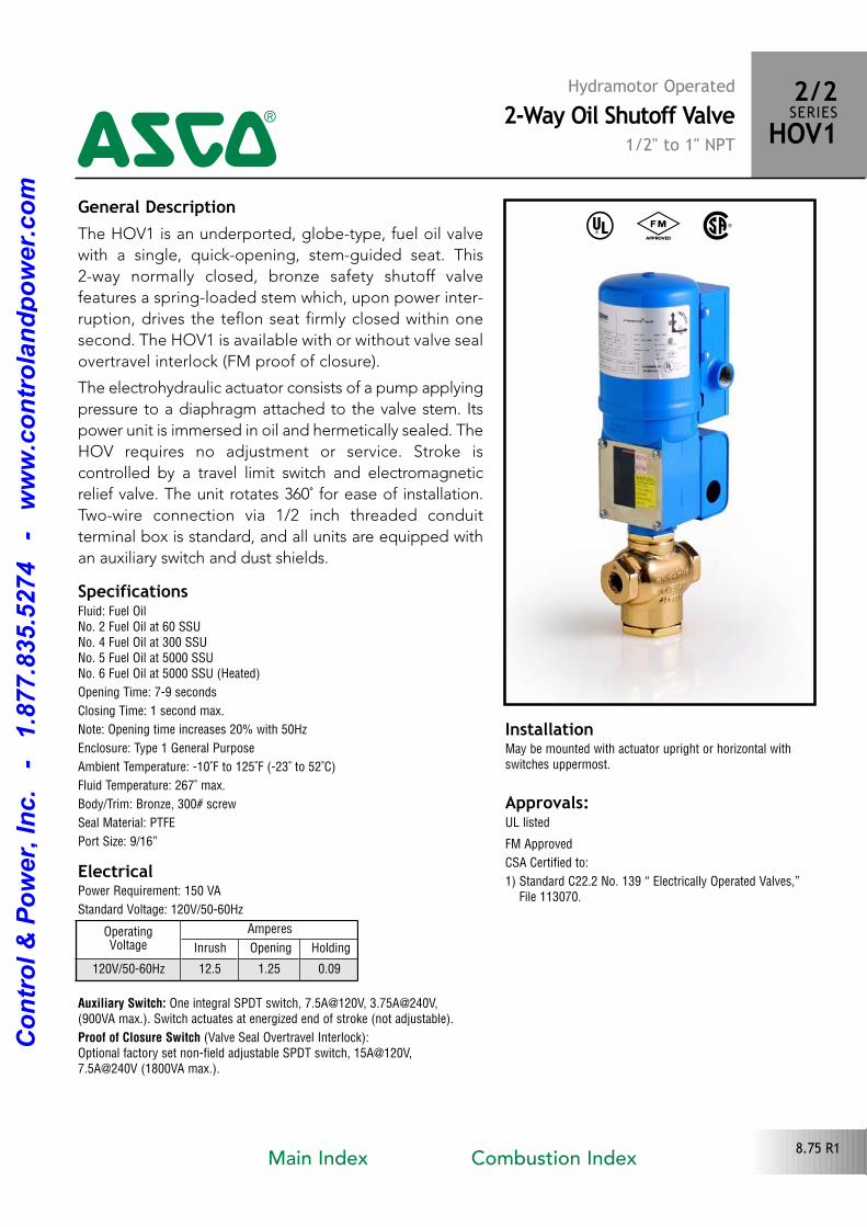
General DescriptionThe HOV1 is an underported, globetype, fuel oil valve
with a single, quickopening, stemguided seat. This
2way normally closed, bronze safety shutoff valve
features a springloaded stem which, upon power inter
ruption, drives the teflon seat firmly closed within one
second. The HOV1 is available with or without valve seal
overtravel interlock (FM proof of closure).
The electrohydraulic actuator consists of a pump applying
pressure to a diaphragm attached to the valve stem. Its
power unit is immersed in oil and hermetically sealed. The
HOV requires no adjustment or service. Stroke is
controlled by a travel limit switch and electromagnetic
relief valve. The unit rotates 360˚ for ease of installation.
Twowire connection via 1/2 inch threaded conduit
terminal box is standard, and all units are equipped with
an auxiliary switch and dust shields.
Electrical
^ # %
Approvals: UL listed
FM Approved
CSA Certified to:
1) Standard C22.2 No. 139 “ Electrically Operated Valves,”File 113070.
Hydramotor Operated2-Way Oil Shutoff Valve
1/2" to 1" NPT
2/2SERIESHOV14
8.75 R1
SpecificationsFluid: Fuel OilNo. 2 Fuel Oil at 60 SSUNo. 4 Fuel Oil at 300 SSUNo. 5 Fuel Oil at 5000 SSUNo. 6 Fuel Oil at 5000 SSU (Heated)
Opening Time: 79 seconds
Closing Time: 1 second max.
Note: Opening time increases 20% with 50Hz
Enclosure: Type 1 General Purpose
Ambient Temperature: 10˚F to 125˚F (23˚ to 52˚C)
Fluid Temperature: 267˚ max.
Body/Trim: Bronze, 300# screw
Seal Material: PTFE
Port Size: 9/16”
Power Requirement: 150 VA
Standard Voltage: 120V/5060Hz
OperatingVoltage
Amperes
Inrush Opening Holding
120V/5060Hz 12.5 1.25 0.09
Auxiliary Switch: One integral SPDT switch, 7.5A@120V, 3.75A@240V,(900VA max.). Switch actuates at energized end of stroke (not adjustable).
Proof of Closure Switch (Valve Seal Overtravel Interlock):Optional factory set nonfield adjustable SPDT switch, 15A@120V,7.5A@240V (1800VA max.).
InstallationMay be mounted with actuator upright or horizontal withswitches uppermost.
Main Index Combustion Index
Co
ntr
ol
& P
ow
er,
In
c.
-
1.8
77.8
35.5
274
-
ww
w.c
on
tro
lan
dp
ow
er.
co
m
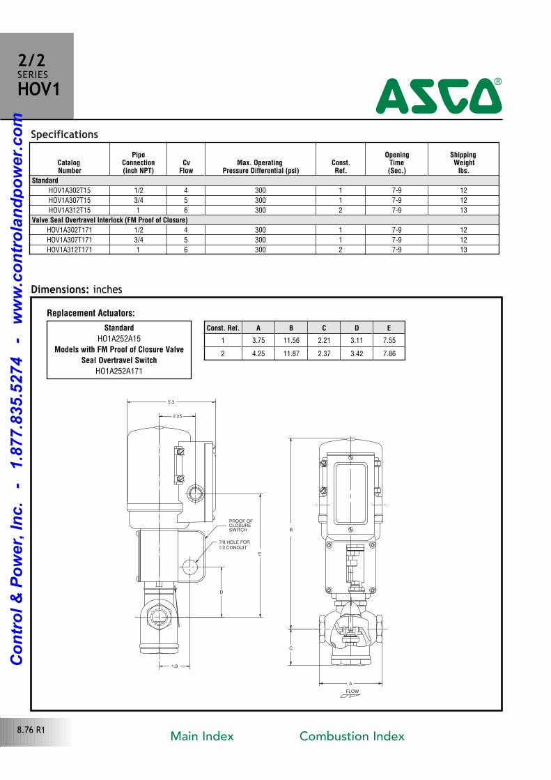
Specifications
B
5.3
E
2.25
C
D
1.8
A
FLOW
7/8 HOLE FOR
1/2 CONDUIT
PROOF OFCLOSURESWITCH
Dimensions: inches
2/2SERIESHOV1
4
8.76 R1
CatalogNumber
PipeConnection(inch NPT)
CvFlow
Max. Operating Pressure Differential (psi)
Const.Ref.
OpeningTime(Sec.)
ShippingWeight
lbs.
Standard
HOV1A302T15 1/2 4 300 1 79 12
HOV1A307T15 3/4 5 300 1 79 12
HOV1A312T15 1 6 300 2 79 13
Valve Seal Overtravel Interlock (FM Proof of Closure)
HOV1A302T171 1/2 4 300 1 79 12
HOV1A307T171 3/4 5 300 1 79 12
HOV1A312T171 1 6 300 2 79 13
Const. Ref. A B C D E
1 3.75 11.56 2.21 3.11 7.55
2 4.25 11.87 2.37 3.42 7.86
Standard
HO1A252A15
Models with FM Proof of Closure Valve
Seal Overtravel Switch
HO1A252A171
Replacement Actuators:
Main Index Combustion Index
Co
ntr
ol
& P
ow
er,
In
c.
-
1.8
77.8
35.5
274
-
ww
w.c
on
tro
lan
dp
ow
er.
co
m
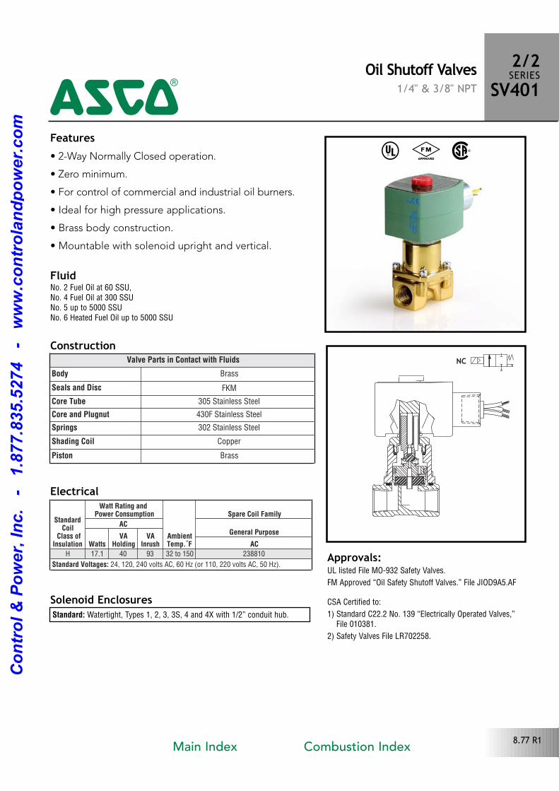
Features• 2Way Normally Closed operation.
• Zero minimum.
• For control of commercial and industrial oil burners.
• Ideal for high pressure applications.
• Brass body construction.
• Mountable with solenoid upright and vertical.
Solenoid Enclosures
Construction
Standard: Watertight, Types 1, 2, 3, 3S, 4 and 4X with 1/2” conduit hub.
Electrical
^ # %
Approvals:UL listed File MO932 Safety Valves.
FM Approved “Oil Safety Shutoff Valves.” File JIOD9A5.AF
CSA Certified to:
1) Standard C22.2 No. 139 “Electrically Operated Valves,” File 010381.
2) Safety Valves File LR702258.
Oil Shutoff Valves1/4" & 3/8" NPT
2/2SERIESSV401
4
8.77 R1
FluidNo. 2 Fuel Oil at 60 SSU, No. 4 Fuel Oil at 300 SSUNo. 5 up to 5000 SSUNo. 6 Heated Fuel Oil up to 5000 SSU
Valve Parts in Contact with Fluids
Body Brass
Seals and Disc FKM
Core Tube 305 Stainless Steel
Core and Plugnut 430F Stainless Steel
Springs 302 Stainless Steel
Shading Coil Copper
Piston Brass
StandardCoil
Class ofInsulation
Watt Rating and Power Consumption
AmbientTemp.˚F
Spare Coil Family
ACGeneral Purpose
WattsVA
HoldingVA
Inrush ACH 17.1 40 93 32 to 150 238810
Standard Voltages: 24, 120, 240 volts AC, 60 Hz (or 110, 220 volts AC, 50 Hz).
Main Index Combustion Index
Co
ntr
ol
& P
ow
er,
In
c.
-
1.8
77.8
35.5
274
-
ww
w.c
on
tro
lan
dp
ow
er.
co
m
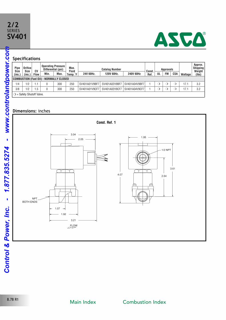
PipeSize(ins.)
OrificeSize(ins.)
CVFlow
Operating PressureDifferential (psi) Max.
FluidTemp.˚F
Catalog NumberConst.Ref.
Approvals
Wattage
Approx.ShippingWeight(lbs)Min. Max. 24V 60Hz. 120V 60Hz. 240V 60Hz UL FM CSA
COMBUSTION (Fuel Oil) - NORMALLY CLOSED
1/4 1/2 1.1 0 300 250 SV401A01V9BF7 SV401A02V9BF7 SV401A04V9BF7 1 � � � 17.1 3.2
3/8 1/2 1.5 0 300 250 SV401A01V9CF7 SV401A02V9CF7 SV401A04V9CF7 1 � � � 17.1 3.2
Specifications
Dimensions: inches
Const. Ref. 1
1/2 NPT
FLOW
NPT
BOTH ENDS
1.92
1.07
2.05
3.04
3.21
2.64
3.61
4.07
1.95
2/2SERIESSV401
4
� = Safety Shutoff Valve.
8.78 R1Main Index Combustion Index
Co
ntr
ol
& P
ow
er,
In
c.
-
1.8
77.8
35.5
274
-
ww
w.c
on
tro
lan
dp
ow
er.
co
m
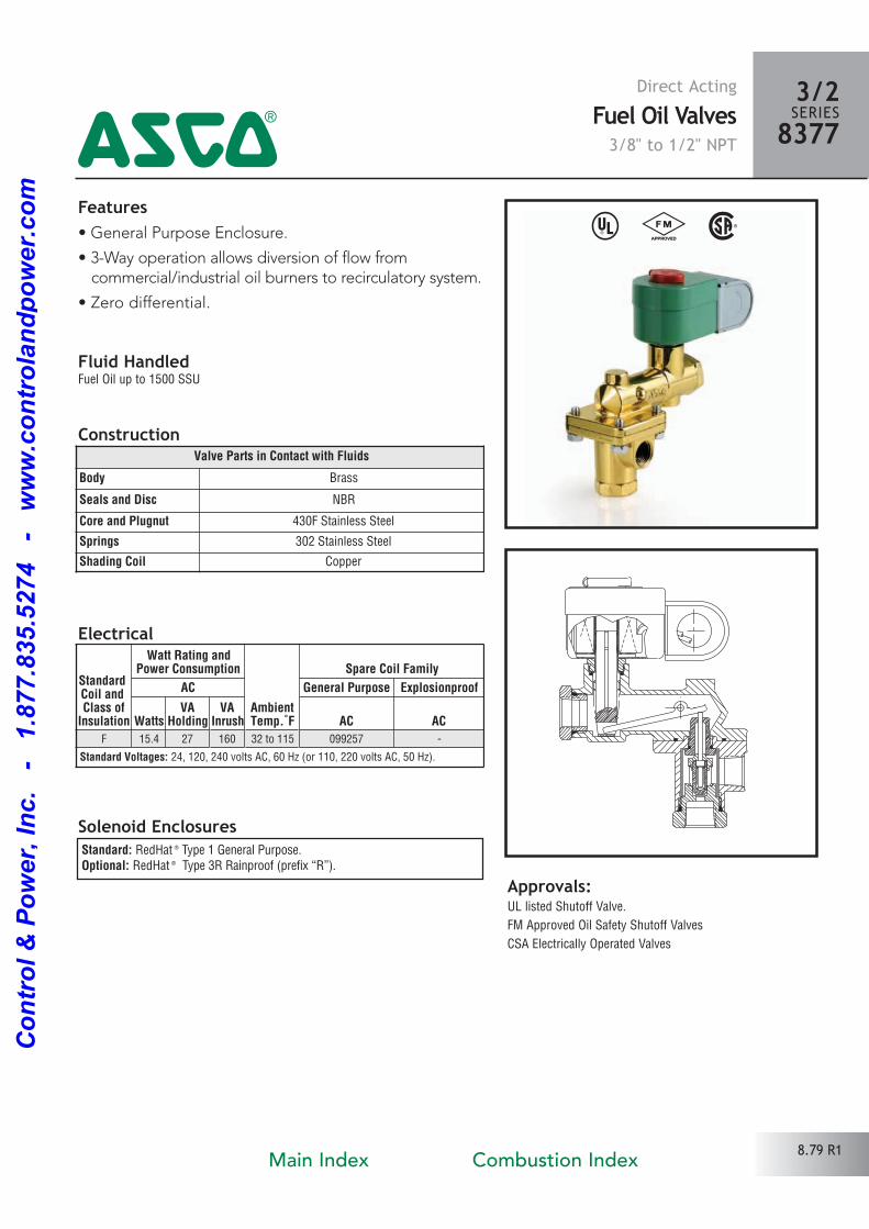
Features• General Purpose Enclosure.
• 3Way operation allows diversion of flow from commercial/industrial oil burners to recirculatory system.
• Zero differential.
Solenoid Enclosures
Construction
Electrical
^ # %
Approvals: UL listed Shutoff Valve.
FM Approved Oil Safety Shutoff Valves
CSA Electrically Operated Valves
Direct ActingFuel Oil Valves3/8" to 1/2" NPT
3/2SERIES83774
8.79 R1
Fluid HandledFuel Oil up to 1500 SSU
Standard: RedHat ® Type 1 General Purpose.Optional: RedHat ® Type 3R Rainproof (prefix “R”).
Valve Parts in Contact with Fluids
Body Brass
Seals and Disc NBR
Core and Plugnut 430F Stainless Steel
Springs 302 Stainless Steel
Shading Coil Copper
StandardCoil and Class of
Insulation
Watt Rating andPower Consumption
AmbientTemp.˚F
Spare Coil Family
AC General Purpose Explosionproof
WattsVA
HoldingVA
Inrush AC AC
F 15.4 27 160 32 to 115 099257
Standard Voltages: 24, 120, 240 volts AC, 60 Hz (or 110, 220 volts AC, 50 Hz).
Main Index Combustion Index
Co
ntr
ol
& P
ow
er,
In
c.
-
1.8
77.8
35.5
274
-
ww
w.c
on
tro
lan
dp
ow
er.
co
m
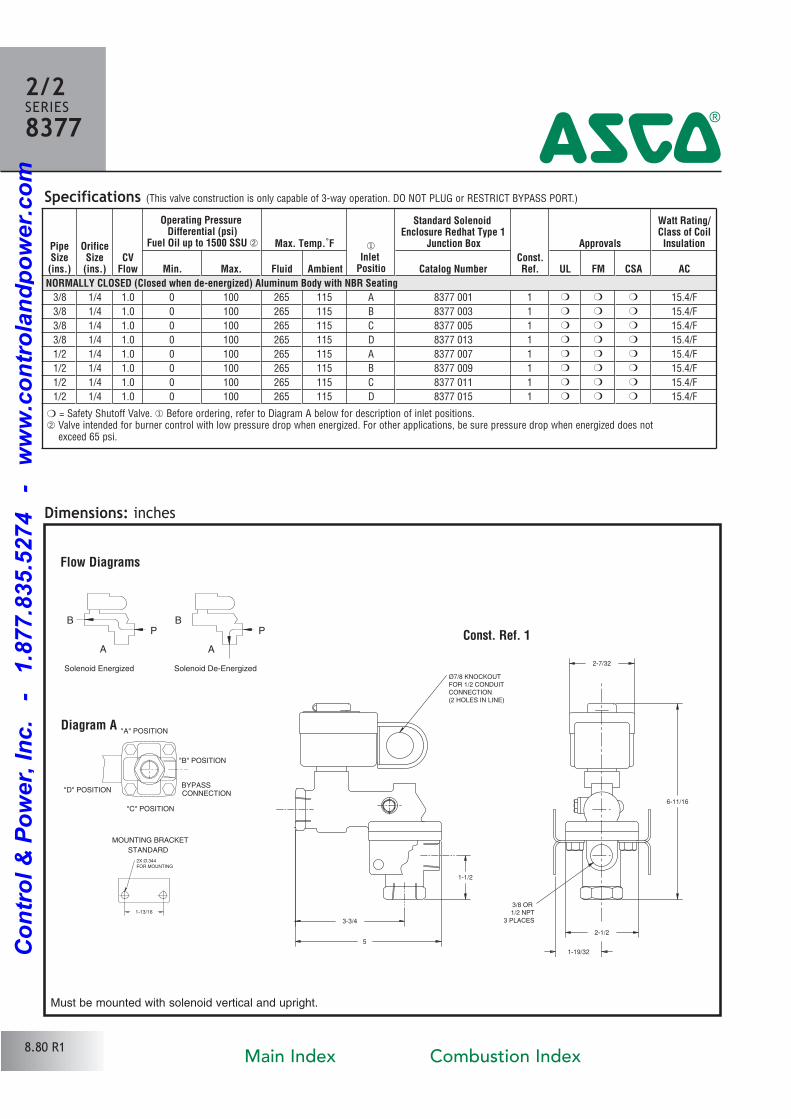
Specifications (This valve construction is only capable of 3way operation. DO NOT PLUG or RESTRICT BYPASS PORT.)
Ø7/8 KNOCKOUT
FOR 1/2 CONDUIT
CONNECTION
(2 HOLES IN LINE)
27/32
611/16
3/8 OR
1/2 NPT
3 PLACES
119/32
21/2
5
33/4
11/2
Dimensions: inches
Const. Ref. 1
2/2SERIES8377
4
Must be mounted with solenoid vertical and upright.
8.80 R1
PipeSize(ins.)
OrificeSize(ins.)
CVFlow
Operating Pressure Differential (psi)
Fuel Oil up to 1500 SSU Max. Temp.˚F �Inlet
Positio
Standard Solenoid Enclosure Redhat Type 1
Junction Box
Const.Ref.
Approvals
Watt Rating/Class of CoilInsulation
Min. Max. Fluid Ambient Catalog Number UL FM CSA AC
NORMALLY CLOSED (Closed when de-energized) Aluminum Body with NBR Seating
3/8 1/4 1.0 0 100 265 115 A 8377 001 1 � � � 15.4/F
3/8 1/4 1.0 0 100 265 115 B 8377 003 1 � � � 15.4/F
3/8 1/4 1.0 0 100 265 115 C 8377 005 1 � � � 15.4/F
3/8 1/4 1.0 0 100 265 115 D 8377 013 1 � � � 15.4/F
1/2 1/4 1.0 0 100 265 115 A 8377 007 1 � � � 15.4/F
1/2 1/4 1.0 0 100 265 115 B 8377 009 1 � � � 15.4/F
1/2 1/4 1.0 0 100 265 115 C 8377 011 1 � � � 15.4/F
1/2 1/4 1.0 0 100 265 115 D 8377 015 1 � � � 15.4/F
� = Safety Shutoff Valve. � Before ordering, refer to Diagram A below for description of inlet positions. Valve intended for burner control with low pressure drop when energized. For other applications, be sure pressure drop when energized does not
exceed 65 psi.
113/16
2X Ø.344
FOR MOUNTING
B
A
PB
A
P
Solenoid Energized Solenoid DeEnergized
MOUNTING BRACKET
STANDARD
"A" POSITION
"C" POSITION
"D" POSITION
"B" POSITION
BYPASSCONNECTION
Flow Diagrams
Diagram A
Main Index Combustion Index
Co
ntr
ol
& P
ow
er,
In
c.
-
1.8
77.8
35.5
274
-
ww
w.c
on
tro
lan
dp
ow
er.
co
m
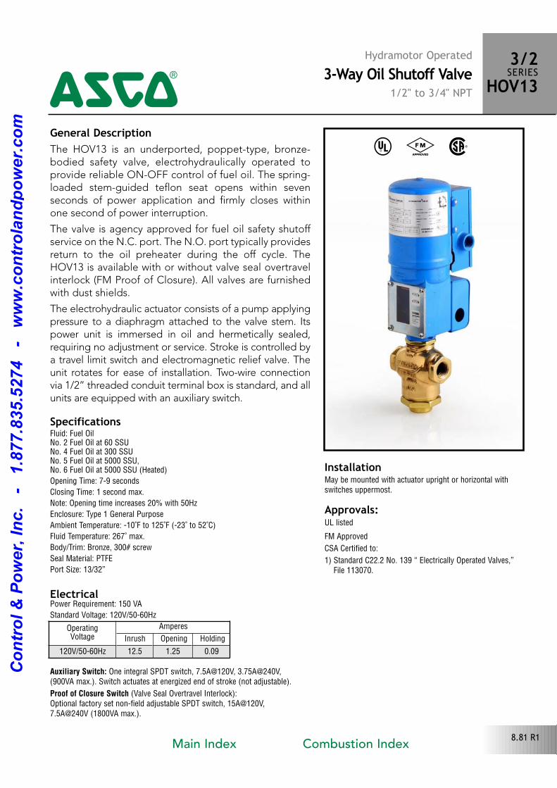
General DescriptionThe HOV13 is an underported, poppettype, bronzebodied safety valve, electrohydraulically operated toprovide reliable ONOFF control of fuel oil. The springloaded stemguided teflon seat opens within seven seconds of power application and firmly closes withinone second of power interruption.
The valve is agency approved for fuel oil safety shutoff service on the N.C. port. The N.O. port typically providesreturn to the oil preheater during the off cycle. TheHOV13 is available with or without valve seal overtravelinterlock (FM Proof of Closure). All valves are furnishedwith dust shields.
The electrohydraulic actuator consists of a pump applyingpressure to a diaphragm attached to the valve stem. Itspower unit is immersed in oil and hermetically sealed,requiring no adjustment or service. Stroke is controlled bya travel limit switch and electromagnetic relief valve. Theunit rotates for ease of installation. Twowire connectionvia 1/2” threaded conduit terminal box is standard, and allunits are equipped with an auxiliary switch.
Electrical
Approvals: UL listed
FM Approved
CSA Certified to:
1) Standard C22.2 No. 139 “ Electrically Operated Valves,”File 113070.
Hydramotor Operated3-Way Oil Shutoff Valve
1/2" to 3/4" NPT
3/2SERIESHOV134
8.81 R1
SpecificationsFluid: Fuel OilNo. 2 Fuel Oil at 60 SSU No. 4 Fuel Oil at 300 SSUNo. 5 Fuel Oil at 5000 SSU,No. 6 Fuel Oil at 5000 SSU (Heated)
Opening Time: 79 seconds
Closing Time: 1 second max.
Note: Opening time increases 20% with 50Hz
Enclosure: Type 1 General Purpose
Ambient Temperature: 10˚F to 125˚F (23˚ to 52˚C)
Fluid Temperature: 267˚ max.
Body/Trim: Bronze, 300# screw
Seal Material: PTFE
Port Size: 13/32”
Power Requirement: 150 VA
Standard Voltage: 120V/5060Hz
Auxiliary Switch: One integral SPDT switch, 7.5A@120V, 3.75A@240V,(900VA max.). Switch actuates at energized end of stroke (not adjustable).
Proof of Closure Switch (Valve Seal Overtravel Interlock):Optional factory set nonfield adjustable SPDT switch, 15A@120V,7.5A@240V (1800VA max.).
InstallationMay be mounted with actuator upright or horizontal withswitches uppermost.
OperatingVoltage
Amperes
Inrush Opening Holding
120V/5060Hz 12.5 1.25 0.09
^ # %
Main Index Combustion Index
Co
ntr
ol
& P
ow
er,
In
c.
-
1.8
77.8
35.5
274
-
ww
w.c
on
tro
lan
dp
ow
er.
co
m
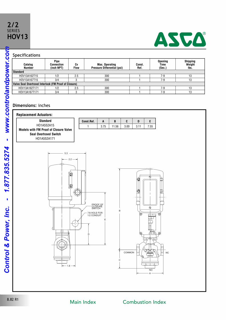
Specifications
1.8
E
B
C
D
7/8 HOLE FOR1/2 CONDUIT
PROOF OFCLOSURESWITCH
COMMON NC
NO
2.2
5.3
A
Dimensions: inches
2/2SERIESHOV13
4
8.82 R1
Standard
HO1A552A15
Models with FM Proof of Closure Valve
Seal Overtravel Switch
HO1A552A171
Replacement Actuators:
Const.Ref. A B C D E
1 3.75 11.56 3.00 3.11 7.55
CatalogNumber
PipeConnection(inch NPT)
CvFlow
Max. Operating Pressure Differential (psi)
Const.Ref.
OpeningTime(Sec.)
ShippingWeight
lbs.
Standard
HOV13A162T15 1/2 2.5 300 1 79 13
HOV13A167T15 3/4 3 300 1 79 13
Valve Seal Overtravel Interlock (FM Proof of Closure)
HOV13A162T171 1/2 2.5 300 1 79 13
HOV13A167T171 3/4 3 300 1 79 13
Main Index Combustion Index
Co
ntr
ol
& P
ow
er,
In
c.
-
1.8
77.8
35.5
274
-
ww
w.c
on
tro
lan
dp
ow
er.
co
m
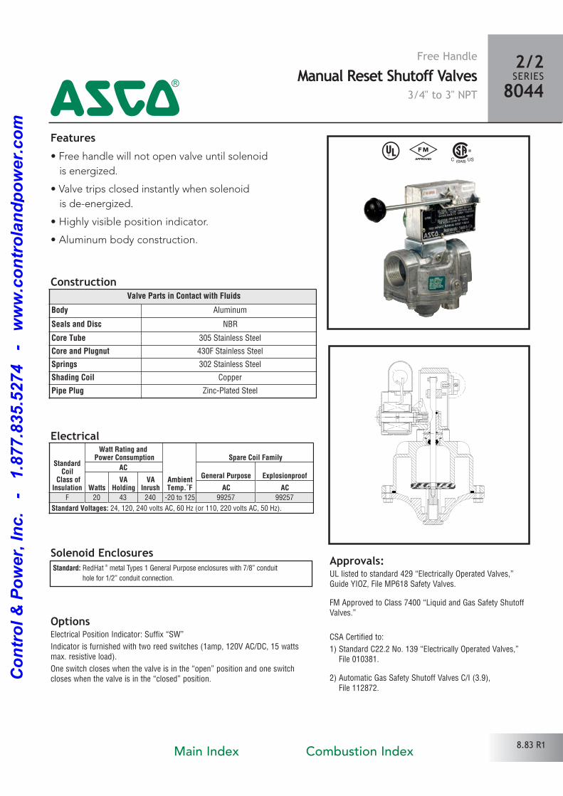
Features• Free handle will not open valve until solenoid
is energized.
• Valve trips closed instantly when solenoid
is deenergized.
• Highly visible position indicator.
• Aluminum body construction.
Solenoid Enclosures
Construction
Standard: RedHat ® metal Types 1 General Purpose enclosures with 7/8” conduit
hole for 1/2” conduit connection.
Electrical
^ #
Approvals:UL listed to standard 429 “Electrically Operated Valves,”Guide YIOZ, File MP618 Safety Valves.
FM Approved to Class 7400 “Liquid and Gas Safety ShutoffValves.”
CSA Certified to:
1) Standard C22.2 No. 139 “Electrically Operated Valves,”File 010381.
2) Automatic Gas Safety Shutoff Valves C/I (3.9), File 112872.
Valve Parts in Contact with Fluids
Body Aluminum
Seals and Disc NBR
Core Tube 305 Stainless Steel
Core and Plugnut 430F Stainless Steel
Springs 302 Stainless Steel
Shading Coil Copper
Pipe Plug ZincPlated Steel
Free HandleManual Reset Shutoff Valves
3/4" to 3" NPT
2/2SERIES8044
4
StandardCoil
Class ofInsulation
Watt Rating and Power Consumption
AmbientTemp.˚F
Spare Coil Family
ACGeneral Purpose Explosionproof
WattsVA
HoldingVA
Inrush AC ACF 20 43 240 20 to 125 99257 99257
Standard Voltages: 24, 120, 240 volts AC, 60 Hz (or 110, 220 volts AC, 50 Hz).
OptionsElectrical Position Indicator: Suffix “SW”
Indicator is furnished with two reed switches (1amp, 120V AC/DC, 15 wattsmax. resistive load).
One switch closes when the valve is in the “open” position and one switchcloses when the valve is in the “closed” position.
8.83 R1Main Index Combustion Index
Co
ntr
ol
& P
ow
er,
In
c.
-
1.8
77.8
35.5
274
-
ww
w.c
on
tro
lan
dp
ow
er.
co
m
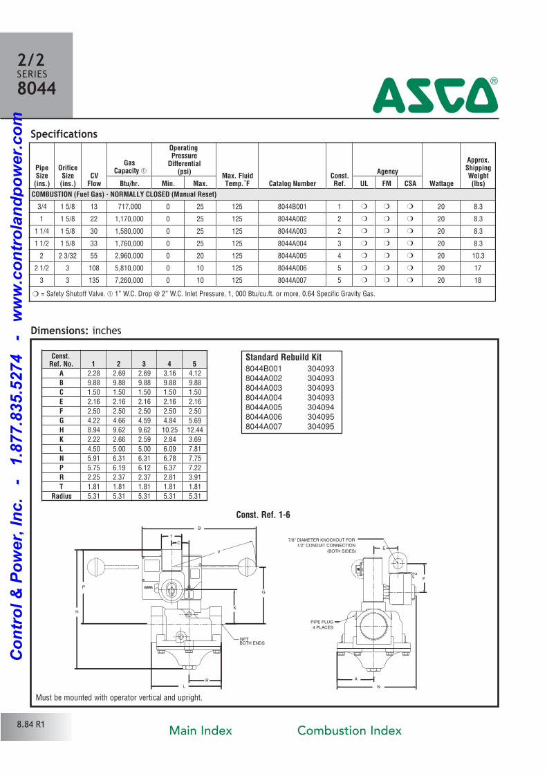
PipeSize(ins.)
OrificeSize(ins.)
CVFlow
GasCapacity �
OperatingPressure
Differential(psi)
Max. FluidTemp.˚F Catalog Number
Const.Ref.
Agency
Wattage
Approx.ShippingWeight(lbs)Btu/hr. Min. Max. UL FM CSA
COMBUSTION (Fuel Gas) - NORMALLY CLOSED (Manual Reset)
3/4 1 5/8 13 717,000 0 25 125 8044B001 1 � � � 20 8.3
1 1 5/8 22 1,170,000 0 25 125 8044A002 2 � � � 20 8.3
1 1/4 1 5/8 30 1,580,000 0 25 125 8044A003 2 � � � 20 8.3
1 1/2 1 5/8 33 1,760,000 0 25 125 8044A004 3 � � � 20 8.3
2 2 3/32 55 2,960,000 0 20 125 8044A005 4 � � � 20 10.3
2 1/2 3 108 5,810,000 0 10 125 8044A006 5 � � � 20 17
3 3 135 7,260,000 0 10 125 8044A007 5 � � � 20 18
Specifications
Dimensions: inches
L
R
H
P
B
K
G
T
C
V
N
A
F
E
NPTBOTH ENDS
PIPE PLUG
4 PLACES
(BOTH SIDES)
7/8" DIAMETER KNOCKOUT FOR
1/2" CONDUIT CONNECTION
Const.Ref. No. 1 2 3 4 5
A 2.28 2.69 2.69 3.16 4.12
B 9.88 9.88 9.88 9.88 9.88
C 1.50 1.50 1.50 1.50 1.50
E 2.16 2.16 2.16 2.16 2.16
F 2.50 2.50 2.50 2.50 2.50
G 4.22 4.66 4.59 4.84 5.69
H 8.94 9.62 9.62 10.25 12.44
K 2.22 2.66 2.59 2.84 3.69
L 4.50 5.00 5.00 6.09 7.81
N 5.91 6.31 6.31 6.78 7.75
P 5.75 6.19 6.12 6.37 7.22
R 2.25 2.37 2.37 2.81 3.91
T 1.81 1.81 1.81 1.81 1.81
Radius 5.31 5.31 5.31 5.31 5.31
2/2SERIES8044
4
� = Safety Shutoff Valve. � 1” W.C. Drop @ 2” W.C. Inlet Pressure, 1, 000 Btu/cu.ft. or more, 0.64 Specific Gravity Gas.
Must be mounted with operator vertical and upright.
Standard Rebuild Kit8044B001 3040938044A002 3040938044A003 3040938044A004 3040938044A005 3040948044A006 3040958044A007 304095
Const. Ref. 1-6
8.84 R1Main Index Combustion Index
Co
ntr
ol
& P
ow
er,
In
c.
-
1.8
77.8
35.5
274
-
ww
w.c
on
tro
lan
dp
ow
er.
co
m
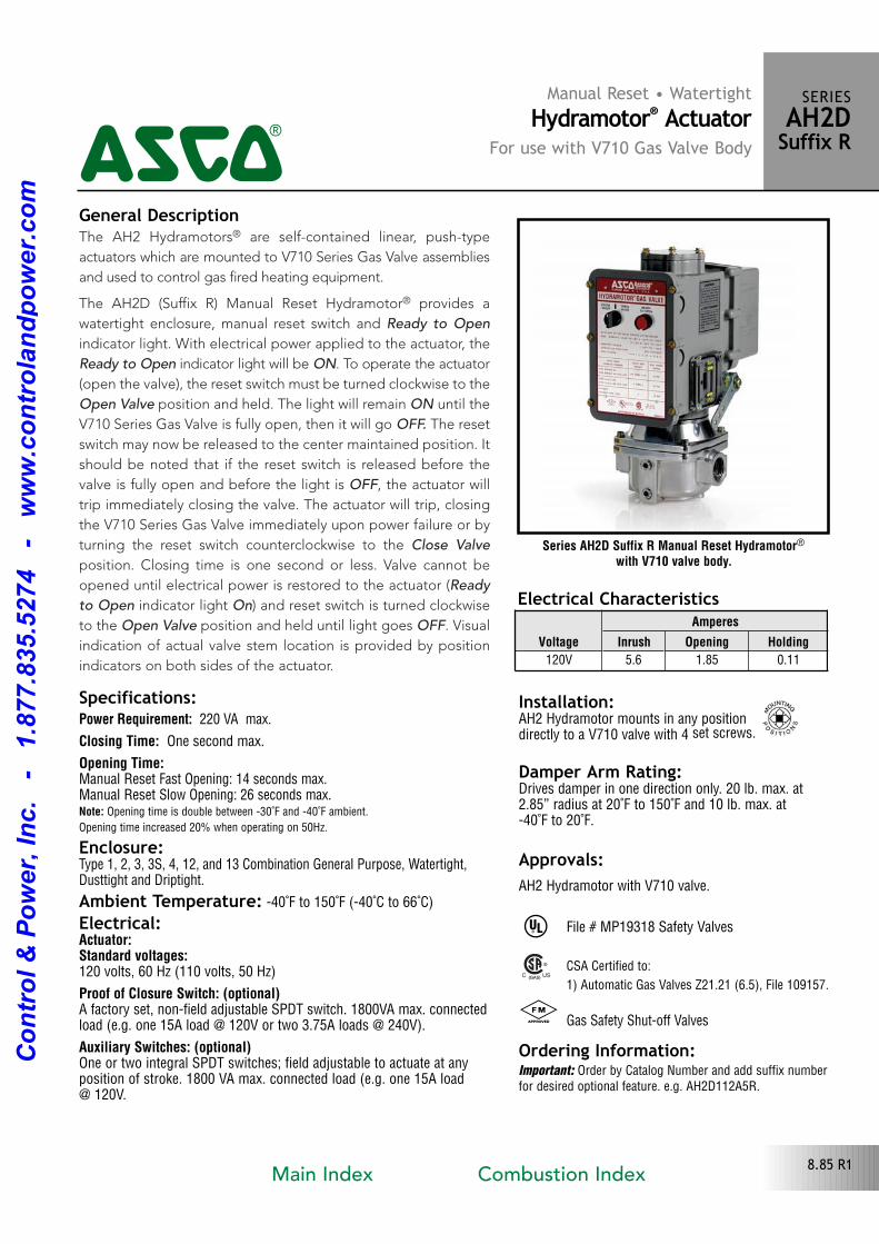
The AH2 Hydramotors® are selfcontained linear, pushtype
actuators which are mounted to V710 Series Gas Valve assemblies
and used to control gas fired heating equipment.
The AH2D (Suffix R) Manual Reset Hydramotor® provides a
watertight enclosure, manual reset switch and Ready to Open
indicator light. With electrical power applied to the actuator, the
Ready to Open indicator light will be ON. To operate the actuator
(open the valve), the reset switch must be turned clockwise to the
Open Valve position and held. The light will remain ON until the
V710 Series Gas Valve is fully open, then it will go OFF. The reset
switch may now be released to the center maintained position. It
should be noted that if the reset switch is released before the
valve is fully open and before the light is OFF, the actuator will
trip immediately closing the valve. The actuator will trip, closing
the V710 Series Gas Valve immediately upon power failure or by
turning the reset switch counterclockwise to the Close Valve
position. Closing time is one second or less. Valve cannot be
opened until electrical power is restored to the actuator (Ready
to Open indicator light On) and reset switch is turned clockwise
to the Open Valve position and held until light goes OFF. Visual
indication of actual valve stem location is provided by position
indicators on both sides of the actuator.
Series AH2D Suffix R Manual Reset Hydramotor®
with V710 valve body.
Manual Reset • Watertight Hydramotor® Actuator
For use with V710 Gas Valve Body
SERIESAH2DSuffix R
4
Specifications:Power Requirement: 220 VA max.
Closing Time: One second max.
Opening Time:Manual Reset Fast Opening: 14 seconds max.Manual Reset Slow Opening: 26 seconds max.Note: Opening time is double between 30˚F and 40˚F ambient.
Opening time increased 20% when operating on 50Hz.
Enclosure:Type 1, 2, 3, 3S, 4, 12, and 13 Combination General Purpose, Watertight,Dusttight and Driptight.
Ambient Temperature: 40˚F to 150˚F (40˚C to 66˚C)
Electrical:Actuator:Standard voltages:120 volts, 60 Hz (110 volts, 50 Hz)
Proof of Closure Switch: (optional)A factory set, nonfield adjustable SPDT switch. 1800VA max. connectedload (e.g. one 15A load @ 120V or two 3.75A loads @ 240V).
Auxiliary Switches: (optional)One or two integral SPDT switches; field adjustable to actuate at any position of stroke. 1800 VA max. connected load (e.g. one 15A load @ 120V.
General Description
Installation: AH2 Hydramotor mounts in any position directly to a V710 valve with 4 set screws.
Approvals:AH2 Hydramotor with V710 valve.
^
# Gas Safety Shutoff Valves
Ordering Information:Important: Order by Catalog Number and add suffix numberfor desired optional feature. e.g. AH2D112A5R.
File # MP19318 Safety Valves
Electrical CharacteristicsVoltage
Amperes
Inrush Opening Holding
120V 5.6 1.85 0.11
8.85 R1
Damper Arm Rating:Drives damper in one direction only. 20 lb. max. at2.85” radius at 20˚F to 150˚F and 10 lb. max. at 40˚F to 20˚F.
CSA Certified to:
1) Automatic Gas Valves Z21.21 (6.5), File 109157.
Main Index Combustion Index
Co
ntr
ol
& P
ow
er,
In
c.
-
1.8
77.8
35.5
274
-
ww
w.c
on
tro
lan
dp
ow
er.
co
m
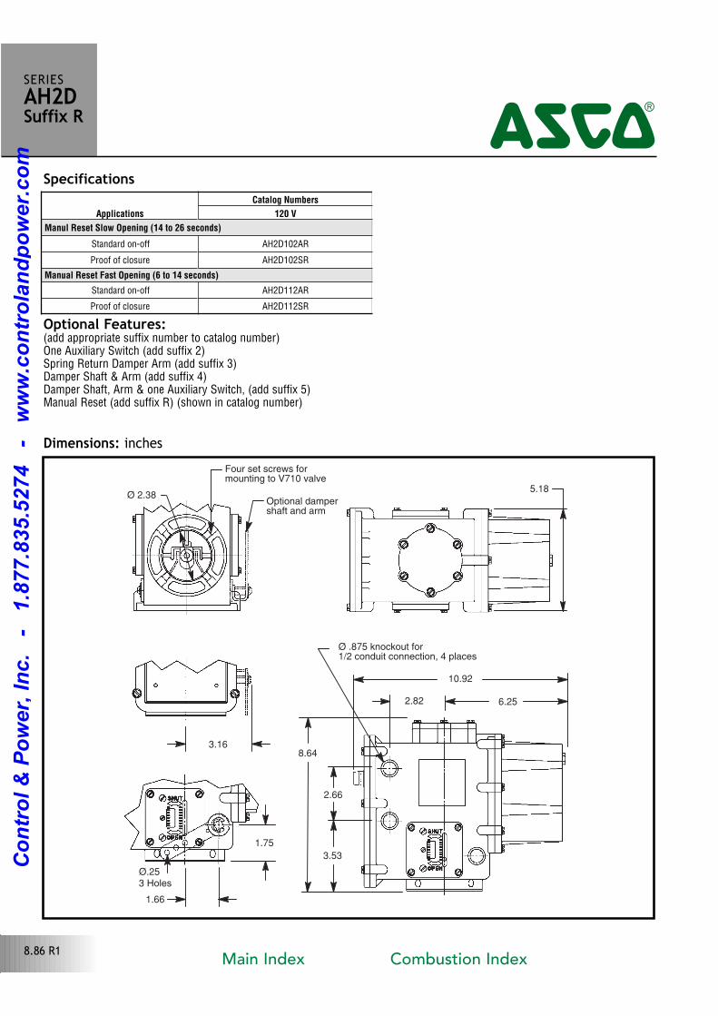
1.66
Ø.253 Holes
1.75
3.16
Ø 2.38
Four set screws for mounting to V710 valve
Optional dampershaft and arm
5.18
Ø .875 knockout for 1/2 conduit connection, 4 places
10.92
2.82 6.25
8.64
2.66
3.53
Optional Features: (add appropriate suffix number to catalog number)One Auxiliary Switch (add suffix 2)Spring Return Damper Arm (add suffix 3)Damper Shaft & Arm (add suffix 4)Damper Shaft, Arm & one Auxiliary Switch, (add suffix 5)Manual Reset (add suffix R) (shown in catalog number)
SERIESAH2DSuffix R
4
Dimensions: inches
8.86 R1
SpecificationsApplications
Catalog Numbers
120 V
Manul Reset Slow Opening (14 to 26 seconds)
Standard onoff AH2D102AR
Proof of closure AH2D102SR
Manual Reset Fast Opening (6 to 14 seconds)
Standard onoff AH2D112AR
Proof of closure AH2D112SR
Main Index Combustion Index
Co
ntr
ol
& P
ow
er,
In
c.
-
1.8
77.8
35.5
274
-
ww
w.c
on
tro
lan
dp
ow
er.
co
m
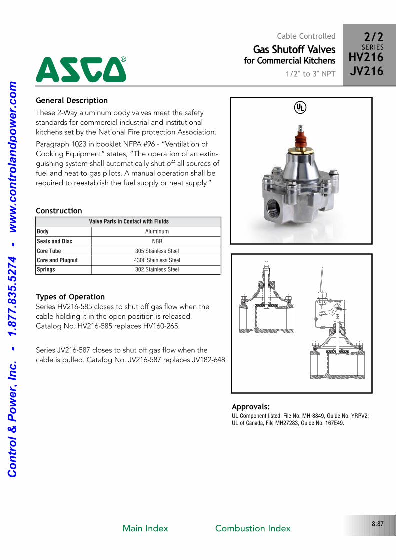
General DescriptionThese 2Way aluminum body valves meet the safety
standards for commercial industrial and institutional
kitchens set by the National Fire protection Association.
Paragraph 1023 in booklet NFPA #96 “Ventilation of
Cooking Equipment” states, “The operation of an extin
guishing system shall automatically shut off all sources of
fuel and heat to gas pilots. A manual operation shall be
required to reestablish the fuel supply or heat supply.”
Construction
^
Approvals:UL Component listed, File No. MH8849, Guide No. YRPV2;UL of Canada, File MH27283, Guide No. 167E49.
Cable ControlledGas Shutoff Valves
for Commercial Kitchens1/2" to 3" NPT4
8.87
Types of OperationSeries HV216585 closes to shut off gas flow when the
cable holding it in the open position is released.
Catalog No. HV216585 replaces HV160265.
Series JV216587 closes to shut off gas flow when the
cable is pulled. Catalog No. JV216587 replaces JV182648
Valve Parts in Contact with Fluids
Body Aluminum
Seals and Disc NBR
Core Tube 305 Stainless Steel
Core and Plugnut 430F Stainless Steel
Springs 302 Stainless Steel
2/2SERIESHV216
JV216
Main Index Combustion Index
Co
ntr
ol
& P
ow
er,
In
c.
-
1.8
77.8
35.5
274
-
ww
w.c
on
tro
lan
dp
ow
er.
co
m
Specifications
Dimensions: inches
2/2SERIESHV216JV216 4
Note: Max is the full open position. Do not exceed as distortion of internal parts may result.
8.88
PipeSize
(ins.)
OrificeSize
(ins.)CV
Flow
Fluid & AmbientTemp.˚F
Operating PressureDifferential (psi)
Catalog NumbersCable Operation Agency
Min Max. Min. Max. Release to Close Pull to Close UL
NORMALLY CLOSED (Closed when de-energized)
1/2 3/4 5.2 32 132 0 5 HV2165858 JV2165871 �3/4 3/4 6.5 32 132 0 5 HV2165851 JV2165872 �1 1 5/8 24 32 132 0 5 HV2165852 JV2165873 �
1 1/4 1 5/8 34 32 132 0 5 HV2165853 JV2165874 �1 1/2 1 5/8 38 32 132 0 5 HV2165854 JV2165875 �
2 2 3/32 54 32 132 0 5 HV2165855 JV2165876 �2 1/2 3 110 32 132 0 5 HV2165856 JV2165877 �
3 3 138 32 132 0 5 HV2165857 JV2165878 �� = Safety Shutoff Valve. Safe working pressure 50 psig.
Catalog No. B G H L P W
JV2165871 1 3/8 1 9/64 6 9/16 2 3/4 6 2 23/64
JV2165872 1 21/32 1 5/32 7 3 5/16 6 3/16 2 11/32
JV2165873 2 3/8 2 11/16 8 13/16 5 7 1/2 5 3/8
JV2165874 2 3/8 2 11/16 8 13/16 5 7 1/2 5 3/8
JV2165875 2 3/8 2 11/16 8 13/16 5 7 9/16 5 3/8
JV2165876 2 13/16 3 5/32 9 17/32 6 3/32 8 1/32 6 5/16
JV2165877 3 29/32 4 1/8 11 25/64 7 51/64 9 1/16 7 61/64
JV2165878 3 57/64 4 1/8 11 25/64 7 25/32 9 1/16 7 61/64
Catalog No. B F G H L P W
HV2165858 1 3/8 3/16 1 9/64 4 3/8 2 3/4 3 13/16 2 29/64
HV2165851 1 21/32 3/16 1 9/64 4 13/16 3 5/16 4 2 29/64
HV2165852 2 3/8 17/32 2 11/16 7 5/32 5 5 27/32 5 3/8
HV2165853 2 3/8 17/32 2 11/16 7 5/32 5 5 27/32 5 3/8
HV2165854 2 3/8 17/32 2 11/16 7 5/32 5 5 51/64 5 3/8
HV2165855 2 13/16 39/64 3 5/32 7 3/4 6 3/32 6 1/4 6 5/16
HV2165856 3 29/32 29/32 4 1/8 9 61/64 7 51/64 7 5/8 7 61/64
HV2165857 3 57/64 29/32 4 1/8 9 61/64 7 25/32 7 5/8 7 61/64
H
P
L
B G
W
L
B
H
P
G
W
F MAX.
SEE NOTE
Main Index Combustion Index
Co
ntr
ol
& P
ow
er,
In
c.
-
1.8
77.8
35.5
274
-
ww
w.c
on
tro
lan
dp
ow
er.
co
m
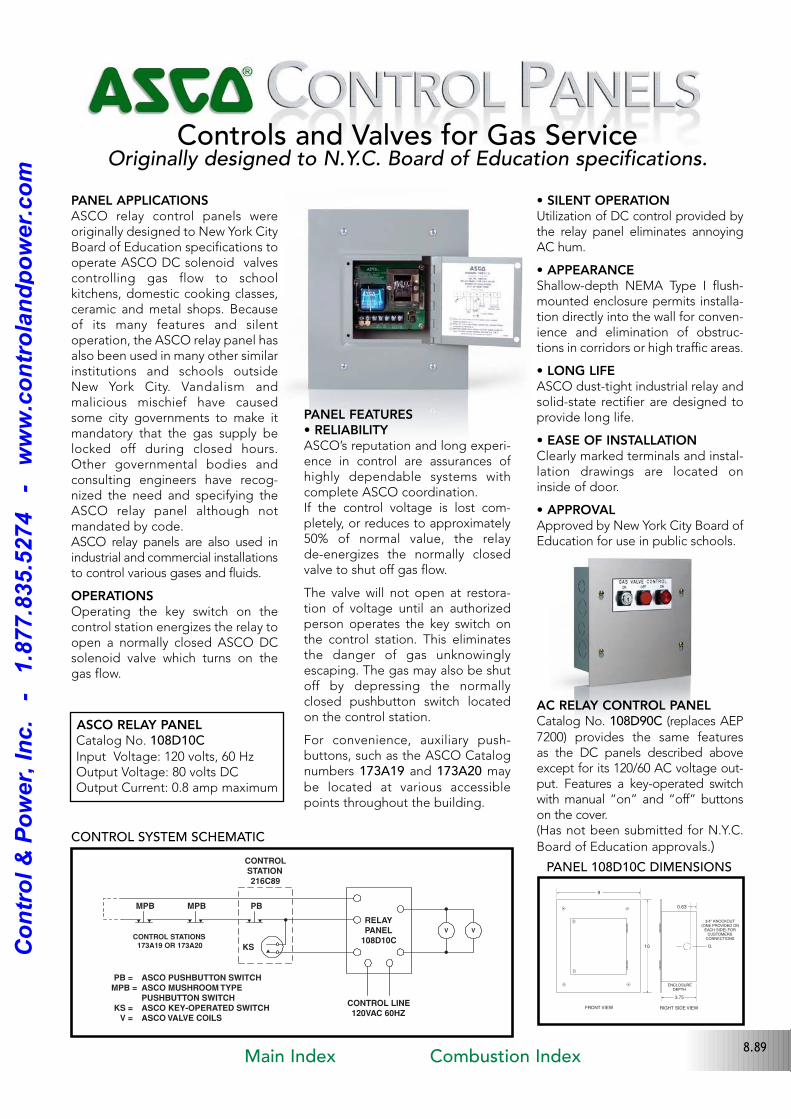
Controls and Valves for Gas ServiceOriginally designed to N.Y.C. Board of Education specifications.
PANEL APPLICATIONSASCO relay control panels wereoriginally designed to New York CityBoard of Education specifications tooperate ASCO DC solenoid valvescontrolling gas flow to schoolkitchens, domestic cooking classes,ceramic and metal shops. Becauseof its many features and silent operation, the ASCO relay panel hasalso been used in many other similarinstitutions and schools outsideNew York City. Vandalism andmalicious mischief have causedsome city governments to make itmandatory that the gas supply belocked off during closed hours.Other governmental bodies andconsulting engineers have recognized the need and specifying theASCO relay panel although notmandated by code.ASCO relay panels are also used inindustrial and commercial installationsto control various gases and fluids.
OPERATIONSOperating the key switch on thecontrol station energizes the relay toopen a normally closed ASCO DCsolenoid valve which turns on thegas flow.
PANEL FEATURES• RELIABILITYASCO’s reputation and long experience in control are assurances ofhighly dependable systems withcomplete ASCO coordination.If the control voltage is lost completely, or reduces to approximately50% of normal value, the relay deenergizes the normally closedvalve to shut off gas flow.
The valve will not open at restoration of voltage until an authorizedperson operates the key switch onthe control station. This eliminatesthe danger of gas unknowinglyescaping. The gas may also be shutoff by depressing the normallyclosed pushbutton switch locatedon the control station.
For convenience, auxiliary pushbuttons, such as the ASCO Catalognumbers 173A19 and 173A20 maybe located at various accessiblepoints throughout the building.
• SILENT OPERATIONUtilization of DC control provided bythe relay panel eliminates annoyingAC hum.
• APPEARANCEShallowdepth NEMA Type I flushmounted enclosure permits installation directly into the wall for convenience and elimination of obstructions in corridors or high traffic areas.
• LONG LIFEASCO dusttight industrial relay andsolidstate rectifier are designed toprovide long life.
• EASE OF INSTALLATIONClearly marked terminals and installation drawings are located oninside of door.
• APPROVALApproved by New York City Board ofEducation for use in public schools.
AC RELAY CONTROL PANELCatalog No. 108D90C (replaces AEP7200) provides the same features as the DC panels described aboveexcept for its 120/60 AC voltage output. Features a keyoperated switchwith manual “on” and “off” buttonson the cover. (Has not been submitted for N.Y.C.
Board of Education approvals.)
ASCO RELAY PANEL Catalog No. 108D10CInput Voltage: 120 volts, 60 HzOutput Voltage: 80 volts DCOutput Current: 0.8 amp maximum
RELAY
PANEL
108D10C
V V
KS
PBMPBMPB
CONTROL STATIONS
173A19 OR 173A20
PB = ASCO PUSHBUTTON SWITCH
MPB = ASCO MUSHROOM TYPE
PUSHBUTTON SWITCH
KS = ASCO KEY-OPERATED SWITCH
V = ASCO VALVE COILS
CONTROL LINE
120VAC 60HZ
CONTROL
STATION
216C89
.
.
9
10
.
.
3.75
0.63
FRONT VIEW RIGHT SIDE VIEW
ENCLOSUREDEPTH
CL
3/4" KNOCKOUT(ONE PROVIDED ON
EACH SIDE) FORCUSTOMERS
CONNECTIONS
PANEL 108D10C DIMENSIONS
CONTROL SYSTEM SCHEMATIC
8.89Main Index Combustion Index
Co
ntr
ol
& P
ow
er,
In
c.
-
1.8
77.8
35.5
274
-
ww
w.c
on
tro
lan
dp
ow
er.
co
m
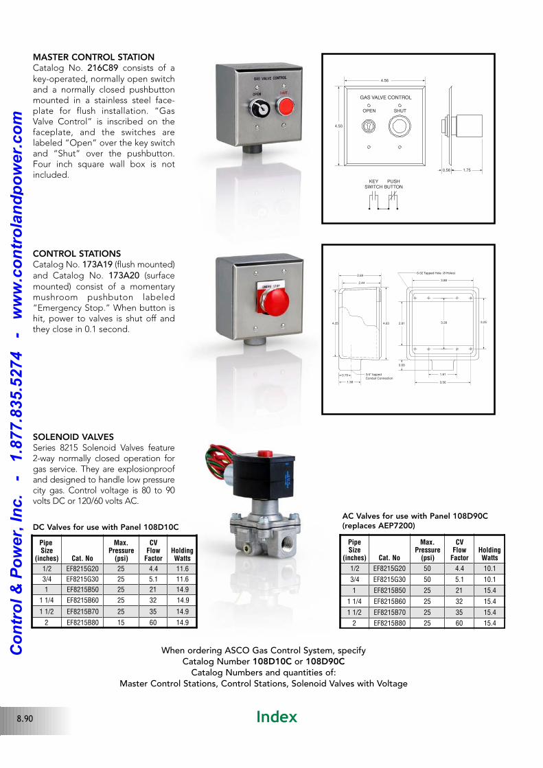
MASTER CONTROL STATIONCatalog No. 216C89 consists of akeyoperated, normally open switchand a normally closed pushbuttonmounted in a stainless steel faceplate for flush installation. “GasValve Control” is inscribed on thefaceplate, and the switches arelabeled “Open” over the key switchand “Shut” over the pushbutton.Four inch square wall box is notincluded.
CONTROL STATIONSCatalog No. 173A19 (flush mounted)and Catalog No. 173A20 (surfacemounted) consist of a momentarymushroom pushbuton labeled“Emergency Stop.” When button ishit, power to valves is shut off andthey close in 0.1 second.
4.50
4.56
GAS VALVE CONTROL
OPEN SHUT
0.56 1.75
KEY
SWITCH
PUSH
BUTTON
2.81 3.28
3.56
1.81
3.25
0.69
3.88
632 Tapped Hole (8 Holes)
4.63
2.69
4.25
2.44
0.75
1.38
3/4" tapped
Conduit Connection
SOLENOID VALVESSeries 8215 Solenoid Valves feature2way normally closed operation forgas service. They are explosionproofand designed to handle low pressurecity gas. Control voltage is 80 to 90volts DC or 120/60 volts AC.
PipeSize
(inches) Cat. No
Max.Pressure
(psi)
CVFlow
FactorHoldingWatts
1/2 EF8215G20 25 4.4 11.6
3/4 EF8215G30 25 5.1 11.6
1 EF8215B50 25 21 14.9
1 1/4 EF8215B60 25 32 14.9
1 1/2 EF8215B70 25 35 14.9
2 EF8215B80 15 60 14.9
When ordering ASCO Gas Control System, specifyCatalog Number 108D10C or 108D90C
Catalog Numbers and quantities of: Master Control Stations, Control Stations, Solenoid Valves with Voltage
DC Valves for use with Panel 108D10C
AC Valves for use with Panel 108D90C(replaces AEP7200)
PipeSize
(inches) Cat. No
Max.Pressure
(psi)
CVFlow
FactorHoldingWatts
1/2 EF8215G20 50 4.4 10.1
3/4 EF8215G30 50 5.1 10.1
1 EF8215B50 25 21 15.4
1 1/4 EF8215B60 25 32 15.4
1 1/2 EF8215B70 25 35 15.4
2 EF8215B80 25 60 15.4
8.90 Index
Co
ntr
ol
& P
ow
er,
In
c.
-
1.8
77.8
35.5
274
-
ww
w.c
on
tro
lan
dp
ow
er.
co
m