Embed Size (px)
Citation preview

Int. J. Nav. Archit. Ocean Eng. (2015) 7:770~783 http://dx.doi.org/10.1515/ijnaoe-2015-0054
pISSN: 2092-6782, eISSN: 2092-6790
ⓒSNAK, 2015
Control of surface defects on plasma-MIG hybrid welds in cryogenic aluminum alloys
Hee-Keun Lee1, Kwang-San Chun1, Sang-Hyeon Park2 and Chung-Yun Kang2,3
1Welding Engineering R&D Group, Daewoo Shipbuilding & Marine Engineering Co., Ltd, Geoje, Korea 2Hybrid Materials Solution National Core Research Center, Pusan National University, Busan, Korea
3Department of Material Science and Engineering, Pusan National University, Busan, Korea
Received 17 January 2015; Revised 24 March 2015; Accepted 4 June 2015
ABSTRACT: Lately, high production rate welding processes for Al alloys, which are used as LNG FPSO cargo con-tainment system material, have been developed to overcome the limit of installation and high rework rates. In particular, plasma-metal inert gas (MIG) hybrid (PMH) welding can be used to obtain a higher deposition rate and lower porosity, while facilitating a cleaning effect by preheating and post heating the wire and the base metal. However, an asymmetric undercut and a black-colored deposit are created on the surface of PMH weld in Al alloys. For controlling the surface defect formation, the wire feeding speed and nozzle diameter in the PMH weld was investigated through arc phenomena with high-speed imaging and metallurgical analysis.
KEY WORDS: Plasma-MIG hybrid welding; Undercut; Smut; Aluminum welding; Wire feeding speed; Nozzle diameter.
INTRODUCTION
In the current global energy market (ExxonMobil, 2014), the interest and demand for Liquefied Natural Gas (LNG) as a green energy source has continuously increased, while the development and supply of cryogenic material containing such energy is very limited.
Furthermore, the necessity for developing independent-type LNG tanks is important because of their robustness and struc-tural flexibility, even though the current membrane-type LNG Cargo Containment System (CCS) has good characteristics for system stability as well as good track record in marine LNG fields. Based on cryogenic material properties, new International Maritime Organization (IMO) type B tanks for LNG Floating Production, Storage, and Offloading (FPSO) systems have been recently developed with aluminum alloys, nickel alloy steels (9% Ni steel or 36% Ni steel), and 304 stainless steel, as Lee et al. (2013) stated.
Aluminum alloys have been employed as cryogenic materials in Kvaerner-Moss (Moss) and self-supporting prismatic-shaped IMO B (SPB) cargo containment systems in LNG carriers since the Conch independent aluminum cargo tanks were utilized in the Methane Princess in 1964. Its excellent mechanical properties at cryogenic and ambient temperatures, combined with its superior corrosion resistance, make it attractive for applications such as LNG tankers or storage tanks. For LNG ship
Corresponding author: Chung-yun Kang, e-mail: [email protected] This is an Open-Access article distributed under the terms of the Creative Commons Attribution Non-Commercial License (http://creativecommons.org/licenses/by-nc/3.0) which permits unrestricted non-commercial use, distribution, and reproduction in any medium, provided the original work is properly cited.
Int. J. Nav. Archit. Ocean Eng. (2015) 7:770~783 771
construction, aluminum has the additional advantage of higher strength and ductility at cryogenic temperatures. The Al 5083 alloy with a thickness of 25-100 mm has been applied in CCS in LNG carriers. Moreover, AC Tungsten Inert
Gas (TIG), all-position Metal Inert Gas (MIG) butt welding, auto-carriage MIG fillet welding, and high-current MIG welding in the flat position have been applied to CCS constructed with Al 5083.
Welding defects in Al welds include porosity, cracks, lack of fusion, and distortion. As Young and Han (1994) stated, Porosity is caused by the difference in the hydrogen solubility between the liquid (0.7 cc/100 g) and solid (0.036 cc/100 g) phases at the melting point of the Al alloy. Porosity is also influenced by temperature distribution in the Al weld pool induced by the electromagnetic force. Cracks are caused by liquidation of the grain boundary during welding and by high shrinkage stress induced by the high expansion coefficient of Al alloys. Lack of fusion is caused by the higher thermal conductivity of Al alloys and by the oxide layer on the Al alloys that has a high melting point (2060 ℃). Therefore, a larger amount of heat is needed in a short time to fuse aluminum alloys compared to steel, or a solid-state joining process is needed to avoid producing a weld pool.
For the purpose of welding defect control and welding productivity improvement, laser-MIG hybrid welding and friction stir welding have been developed as high production rate welding processes for Al alloys as Ferraris and Volpone (2005) and Paik (2009) stated. However, it is difficult to expand these processes to large structures because of their high installation price and applicable thickness limitations.
One alternative is coaxial Plasma-MIG hybrid Welding (PMHW), developed in the 1970s by Essers and Liefkens (1972). The welding process can be defined as a combination of Plasma Arc Welding (PAW) and MIG welding within a single torch, where a filler wire is fed through the plasma nozzle orifice. The PMHW arc is composed of an MIG arc (inner arc) surrounded by a plasma arc (outer arc). The plasma arc also surrounds the MIG wire and weld pool, thus preheating and post-heating the wire and the base metal. Hence, PMHW can obtain a higher deposition rate and lower porosity, and produce a cleaning effect in the Al weld as Mudde (1980) demonstrated.
Regarding the deposition rate, Kim et al. (2012) argued that for a 1.6 mm-diameter wire, the melting rate afforded by plasma- gas metal arc (GMA) hybrid welding was almost three times that afforded by GMA welding. Regarding the porosity, Mudde (1980) argued that hydrogen solubility in the PMH weld was lower than that in the MIG weld because of the lower droplet temperature at the same MIG welding current. Regarding the cleaning effect, Ono et al. (2009) showed the plasma arc produced a physical cleaning effect of oxide film on the aluminum surface.
However, Lee et al. (2014) reported that two kinds of surface defects (asymmetric undercut and smut) are created on the surface of PMH weld in Al 5083. The asymmetric undercut is created near the fusion line of PMH welds by the electromagnetic stirring force induced by high plasma currents over 200 A. The smut is a black-colored deposit on the surface of an MIG weld with Al alloys. Smut contains high vapor pressure elements such as Mg, Zn, and Li from the arc generated between the wire and the edge of the weld pool after short circuit transfer as well as from droplet explosion transfer, which depends on the MIG current. However, two types of smut appeared in the PMH welding bead: Smut Spots (SS) on the welding bead and Smut Inside the welding Bead (SIB). The amount of smut formed on the PMH weld is less than that of the MIG weld. Moreover, SS on the PMH weld is formed by the combination of graphite layers remaining on the droplet and the weld pool, while SIB is generated by combination of asymmetric undercut and metal vapor from a droplet explosion transfer under strong plasma stream and circulation flow induced by the plasma arc with plasma currents over 200 A. Consequently, the plasma current in PMHW produced an asymmetric undercut and could not completely control the smut phenomena.
The main variables of PMHW include the Wire Feeding Speed (WFS) of the MIG power source as well as the plasma current and nozzle diameter of the PAW power source. In the case of MIG welding, WFS influences the MIG welding current and arc length by the self-adjusting effect. Arc length is reduced with increasing WFS. As the arc length decreases, the welding current increases. The welding current increases the temperature and electromagnetic force of MIG arc because electromagnetic force is proportional to welding current density. As the arc temperature increases, droplet transfer changes from globular transfer to explosion transfer in Al 5183, noted by Woods (1980). Consequently, WFS increases the temperature and electro-magnetic force of the MIG arc. In the case of PAW, the nozzle diameter also influences the temperature and electromagnetic force (current density) of the plasma arc by the constricted arc effect (Nishiguchi, 1971; Marconi and Marconi, 2005). Since the temperature and electromagnetic force of the MIG arc and plasma arc in PMHW arc affect the weld pool flow and droplet explosion transfer, the asymmetric undercut and smut phenomena are expected to depend on WFS and nozzle diameter in the

772 Int. J. Nav. Archit. Ocean Eng. (2015) 7:770~783
PMHW. However, there have been few studies about the effect of WFS and the nozzle diameter on the asymmetric undercut and smut phenomena of PMHW.
For the purpose of controlling surface defects, in this study, the effect of WFS and nozzle diameter on the asymmetric undercut and smut formation of Al PMH welds was investigated by arc phenomena with high-speed imaging and metallurgical analysis.
EXPERIMENTAL SETUP
In this study, Al 5083 plates and Al 5183 wire were employed as the base metal and as a welding consumable, respectively. Table 1 shows the chemical composition of the materials used. Brushing and acetone cleaning were performed on the surface of the base metal before welding to remove the effects of oil and dirt on smut formation.
Table 1 Chemical composition of the base metal and filler metal.
Element (wt-%) Si Fe Cu Mn Mg Zn Cr Ti Al
Al 5083 (Thickness : 25 mm) 0.08 0.22 0.07 0.65 4.6 0.01 0.8 0.02 Bal.
Al 5183 (Diameter : 1.2 mm) 0.05 0.09 0.01 0.55 4.7 0.01 0.06 0.01 Bal.
Fig. 1 shows schematic diagram of welding processes used. The PAW and PMHW welding were performed using the
synergy mode of a hybrid welding machine that consisted of a PAW power source (maximum power of 400 A with positive electrode polarity) and an MIG welding power source (maximum power of 400 A with positive electrode polarity). The MIG welding was performed using the DC inverter MIG welding power source (maximum power of 400 A with positive electrode polarity). Bead-on-Plate (BOP) welding was conducted using an automatic carriage with variable plasma current (50-250 A), wire feeding speed (5-20 m/min), and nozzle diameter (9-12 mm) without using a pulse current to remove the pulse effect on smut formation. However, the MIG welding voltage (28 V), welding speed (10 mm/s), shield cap-to-work distance (8 mm), and torch angle (90˚) are fixed.
(a) MIG welding. (b) Plasma arc welding (c) Plasma-MIG Hybrid Welding
(without wire feeding) (with wire feeding) Fig. 1 Schematic diagram of welding process used.
Argon gas was used in all of the welding processes. In the MIG welding process, the flow rate of the shielding gas was 20
L/min. In PAW, the flow rate of the plasma gas and shielding gas was 10 L/min and 15 L/min, respectively In the PMH welding process, the flow rate of MIG gas, plasma gas, and shielding gas was 10 L/min, 10 L/min, and 15 L/min, respectively. The arc phenomena during welding are analyzed using a charge-coupled device (CCD) camera (30 frames/s) and a high-speed camera (10,000 frames/s). As shown in Fig. 2, the front view of the arc phenomena was observed using the CCD camera located parallel to the welding direction for investigating the right and left movement of the arc. The side view of arc phenomena was observed with a high-speed camera located perpendicular to the welding direction for investigating the front and rear movement of the arc. A cross-section of the weld and smut was analyzed using a stereoscope (SM) and an Optical Microscope (OM).

Int. J. Nav. Archit. Ocean Eng. (2015) 7:770~783 773
Fig. 2 Installation location of CCD camera and High-speed camera.
RESULTS AND DISCUSSION
Effect of wire feeding speed on surface defects
Fig. 3 and 4 show the bead surface and transverse cross-sections of the PMH welds with respect to changes in WFS at the constant plasma current of 150 A and 250 A, respectively, with a nozzle diameter of 9 mm. When the plasma current was 150 A, a small size of asymmetric undercut was created near the left fusion line of PMH weld at a WFS of 5 m/min. But the asymmetric undercut was not created as the WFS increased. However, reinforce of welding bead was biased to the right at all of WFS condition. Malinowski-brodnicka et al. (1990) and Lee et al. (2014) argued that these phenomena created by the electro-magnetic stirring force that is induced by the plasma arc, which surrounds the MIG arc in the PMHW arc.
Fig. 3 Bead surface and transverse cross-section of Plasma-MIG Hybrid Weld with increasing wire feeding speed
(plasma current of PMHW: 150 A, nozzle diameter: 9 mm)). (a), (e): Bead surface and transverse cross-section at Wire feeding speed 5 m/min (MIG output current 64 A); (b), (f): Bead surface and transverse cross-section at Wire feeding speed 10 m/min (MIG output current 109 A); (c), (g): Bead surface and transverse cross-section at Wire feeding speed 15 m/min (MIG output current 159 A); (d), (h): Bead surface and transverse cross-section at Wire feeding speed 20 m/min (MIG output current 206 A).
Fig. 4 Bead surface and transverse cross-section of Plasma-MIG Hybrid Weld with increasing wire feeding speed
(plasma current of PMHW: 250 A, nozzle diameter: 9 mm)). (a), (e): Bead surface and transverse cross-section at Wire feeding speed 5 m/min (MIG output current 48 A); (b), (f): Bead surface and transverse cross-section at Wire feeding speed 10 m/min (MIG output current 88 A); (c), (g): Bead surface and transverse cross-section at Wire feeding speed 15 m/min (MIG output current 133 A); (d), (h): Bead surface and transverse cross-section at Wire feeding speed 20 m/min (MIG output current 158 A).

774 Int. J. Nav. Archit. Ocean Eng. (2015) 7:770~783
Smut was created on the left side of the Base Metal (BM) and the Weld Metal (WM) of the PMHW bead at a WFS of 5 m/min, as shown in Fig. 3(a). At a WFS of 10 m/min and 15 m/min (Fig. 3 (b) and (c), respectively), smut spots existed on the PMH weld. Finally, at a WFS of 20 m/min (Fig. 3(d)), smut was created on the right side of the BM.
When the plasma current was 250 A (Fig. 4), there was an asymmetric undercut of the PMH welds accompanied by shape asymmetry of the welding bead. The size of the undercut also decreases as the WFS increases because the amount of welding wire in the welding pool increased. Smut was created on the undercut near the left side of the fusion line at all WFSs. The amount and formation area of smut tends to decrease as the WFS increased.
Based on Figs. 3 and 4, smut is classified into three types. The first type is Smut Outside the welding Bead (SOB) as shown in Fig. 3(a). The second type is smut spot on the welding bead (SS), as shown in Fig. 3(b) and (c). The third type is smut inside the welding bead (SIB), as shown in Fig. 4(a) to (d). The smut created under each welding condition is described in Table 2. The SOB was created when the plasma current is below 200 A. On the other hand, SIB was formed when the plasma current is over 200 A. SS was created when the plasma current ranges 100 A to 200 A at WFS of 10 m/min and 15 m/min.
Table 2 Classification of smut on the Al 5083 bead under different PMH and MIG welding conditions (Nozzle Diameter:
9 mm).
Wire feeding speed (m/min)
Plasma current (A)
0 (MIG) 50 100 150 200 250
5 SOB (5.7 m/min) SOB SOB SOB SOB / SIB SIB
10 SOB (10.9 m/min) SOB SS SS SS / SIB SIB
15 SOB (13.5 m/min) SOB SOB / SS SOB / SS SIB SIB
20 SOB (17.3 m/min) SOB SOB SOB SIB SIB
Arc phenomena analysis of smut formation during metal transfer
Figs. 5, 6 and 7 show successive high-speed camera images of metal transfer during PMHW at a WFS of 5 m/min, 15 m/min and 20 m/min of the sample shown in Figs. 3(a), (c) and (d), respectively.
Fig. 5 Successive high speed camera image of metal transfer during plasma-MIG hybrid welding
at wire feeding speed 5 m/min (Plasma current: 150 A, MIG output current: 64 A).
Fig. 6 Successive high speed camera image of metal transfer during plasma-MIG hybrid welding
at wire feeding speed 15 m/min (Plasma current: 150 A, MIG output current: 159 A).

Int. J. Nav. Archit. Ocean Eng. (2015) 7:770~783 775
Fig. 7 Successive high speed camera image of metal transfer during plasma-MIG hybrid welding
at wire feeding speed 20 m/min (Plasma current: 150 A, MIG output current: 206 A). At a WFS of 5 m/min for SOB formation shown in Fig. 5(a), there are two kinds of arcs in PMHW arc. The inner arc is the
MIG welding arc (MIG arc) and the outer arc is the PAW arc (Plasma arc). The color is different due to the difference of the element contained in the arcs. Ton (1975) found that the inner arc contained the elements from MIG welding wire, but the outer arc are contained only argon through optical spectroscopy analysis. Moreover, the temperature of the plasma arc (13000℃) is 2 times higher than one of the MIG arc (6500 ℃) in the PMHW arc.
At a WFS of 5 m/min for SOB formation shown Fig. 5, in-flight explosion accompanied by spattering occurred near the shield cap. Moreover, the size of MIG arc is similar to one of the plasma arc as shown in Figs. 5(b) to (d). As noted by Kim et al. (2010) and Osaka University (2012), metal vapor and spatter from the in-flight explosion are applied by the plasma stream in the PMHW arc. In addition, there is circulation flow near the plasma arc. According to Tanaka and Tsujimura’s (2012) study, some metal elements with high vapor pressure, such as Al and Mg, can get across the plasma stream and then can be carried on the circulation flow toward the electrode. Therefore, a part of metal vapor can be carried on this circulation flow toward the electrode and then metal vapor can exist in the arc plasma. Consequently, the magnetic pinch force and plasma stream of plasma arc is less strong because of the lower plasma current. The plasma arc did not sufficiently cover the metal vapor from in-flight explosion. Thus, some of the metal vapor is emitted out of the plasma arc, and changes to smut by the reaction of residue oxygen in shielding gas. A part of the smut gets into the plasma by the circulation flow. And the part of smut is stuck in the small asymmetric undercut on the left side near the fusion line as shown in Fig. 3(a). Therefore, the SOB in Fig. 3(a) was created on the left side of the BM and WM.
At a WFS of 15 m/min under the conditions of SS formation in Fig. 6, a stable globular transfer occurs without any spattering. As noted by Lee (2014), the carbon lubricant remaining on the droplet combined with the weld pool and formed the smut spot. In general, the oil free carbon lubricant is used to improve Al wire feedabililty (Anderson and Alcotec, 1990).
At a WFS of 20 m/min for SOB formation shown in Fig. 7, a short circuit transfer occurred that was accompanied by spattering and stable globular transfer. The short circuit transfer is thought to be caused by insufficient plasma arc preheating, compared to high WFS. Therefore, the SOB in Fig. 3(d) is created by spatter and metal vapor from the short circuit transfer.
To determine the location of SOB in Fig. 7, the front view of the PAW and PMHW arc, which is acquired by a CCD camera located parallel to the welding direction, was observed, as shown in Fig. 8. Fig. 8(a) to (c) show CCD images of the PAW arc without wire feeding. At a plasma current of 50 A (Fig. 8(a)), the PAW arc is deflected to the right. As the plasma current increased, the arc deflection decreased, and arc stiffness appeared as shown in Fig. 8(b) to (c). However, the arc is asymmetrically shaped and biased to the right side. According to Lancaster (1986), it is thought that the arc deflection pheno-menon was caused by magnetic arc blowing. Because the electric ground of the PAW power source in PMHW machine is placed on the left side of the base metal, as shown in Fig. 8(j), the electromagnetic field associated with the current flow deflects the arc to the right side of the base metal.
Fig. 8(d) to (f) and (g) to (i) show CCD images of the PMHW arc at a WFS of 10 m/min and 20 m/min, respectively. Under a plasma current of 100 A as shown in Fig. 8(d) and (e), both the PAW and MIG arcs are deflected to the right. That means the direction of the outer plasma arc in PMHW influences the direction of the MIG arc. When the WFS was 20 m/min at plasma currents of 100 A and 150 A as shown in Fig. 8(h) and (i), MIG arcs are deflected to the right. In addition, the spatter emitted out to the right. The direction of spatter and metal vapor is influenced by the direction of the plasma and MIG arcs. Therefore, it is clear that SOB is created on the right side because metal vapor generated by short circuit transfer is affected by the deflection of the plasma and MIG arcs.

776 Int. J. Nav. Archit. Ocean Eng. (2015) 7:770~783
Fig. 8 Front view of PAW and PMHW arc phenomena with increasing plasma current and wire feeding speed using CCD camera. (a), (b), (c): PAW arc of plasma current 50 A, 100 A and 150 A at wire feeding speed 0 m/min; (d), (e), (f): PMHW arc of plasma current 50 A, 100 A and 150 A at wire feeding speed 10 m/min; (g), (h), (i): PMHW arc of plasma current 50 A, 100 A and 150 A at wire feeding speed 20 m/min; (j): Location of electric ground of PAW and MIG power source in PMHW machine
Consequently, at a constant plasma current of 150 A, the type of smut changed from SOB to SS and finally to SOB as the
WFS increased. At 5 m/min, SOB is generated by combination of in-flight explosion near the shield cap and insufficient magnetic pinch force and plasma stream of the plasma arc in the PMHW. However, over 10 m/min, SOB is generated by short circuit transfer.
Based on Table 2 and Fig. 4, SIB is created in the PMH weld over plasma currents of 200 A. As the WFS increased, the amount of smut decreased. To determine the reason for this, changes in the arc phenomena were investigated with increasing WFS. Fig. 9 to 11 show successive high-speed camera images of the metal transfer phenomenon at a constant plasma current of 250 A. When the WFS was 5 m/min, as shown in Fig. 9, in-flight explosion occurred, whereas when WFS was 15 m/min and 20 m/min, as shown in Fig. 10 and 11, pendant explosion and streaming transfer occurred accompanied by pendant explosion.
Fig. 9 Successive high speed camera image of metal transfer during plasma-MIG hybrid welding
at wire feeding speed 5 m/min (Plasma current: 250 A, MIG output current: 48 A).
Fig. 10 Successive high speed camera image of metal transfer during plasma-MIG hybrid welding
at wire feeding speed 15 m/min (Plasma current: 250 A, MIG output current: 133 A).

Int. J. Nav. Archit. Ocean Eng. (2015) 7:770~783 777
Fig. 11 Successive high speed camera image of metal transfer during plasma-MIG hybrid welding
at wire feeding speed 20 m/min (Plasma current: 250 A, MIG output current: 158 A). To investigate the effect of the explosion type on smut formation, the explosion rate was calculated by dividing the total
number of droplets transferred by the number of explosion transfers. The result is presented in Fig. 12. As the WFS increased, the in-flight explosion rate decreased. The pendant explosion rate tended to remain constant after increasing until the WFS reached 10 m/min.
Fig. 12 Variation of explosion rate as increasing wire feeding speed at constant plasma current 250 A.
Based on these results, we found that the decrease in smut formation was due to the decreasing in-flight explosion rate as
the WFS increased. It seems that the decrease in the in-flight explosion rate was caused by the short droplet exposure time in the PMHW arc. Woods (1980) argued that the explosion transfer of MIG welding with Al 5183 wire occurs above a droplet temperature of 1560 °C during transfer, and heat input from the MIG arc influences the droplet temperature. In the PMHW case, the plasma arc as well as the MIG arc influenced the droplet temperature. Indeed, the droplet temperature increases if the ex-posure time to the plasma and MIG arcs in the PMHW arc is long. Fig. 9 and 11 show that the droplet transfer time for the WFS of 5 m/min and 20 m/min were about 15 ms and 7 ms, respectively. Consequently, the in-flight explosion rate decreased due to the reduced droplet exposure time in the PMHW arc as the WFS increased.
The pendant explosion rate tended to remain constant after initially increasing until WFS reached 10 m/min. It seems that the pendant explosion rate has a relationship with the location of liquid column between the droplet and the welding wire in the PMHW arc. The wire liquid column is formed by the temperature of the PMHW arc. Woods (1980) argued that pendant explosion is caused by instability of the liquid column from the temperature and the force induced by the MIG arc. In PMHW, the liquid column is affected by the magnetic pinch force and the plasma stream from the plasma arc as well as the MIG arc. Moreover, Schnick et al. (2006) and Marconi and Marconi. (2005) argued that the forces induced by the plasma arc are strong below the nozzle. Except in the case when the WFS was 5 m/min, the liquid column was located below the plasma nozzle, as shown in Fig. 9. Therefore, the forces to the liquid column with a WFS over 10 m/min were stronger than that required at WFS
778 Int. J. Nav. Archit. Ocean Eng. (2015) 7:770~783
of 5 m/min. After 10 m/min, the force was similar because the plasma current was the same. Due to this reason, it seems that the pendant explosion rate showed a tendency to remain constant after increasing initially until WFS reached 10 m/min.
Comparison of welding condition area between smut formation and metal transfer
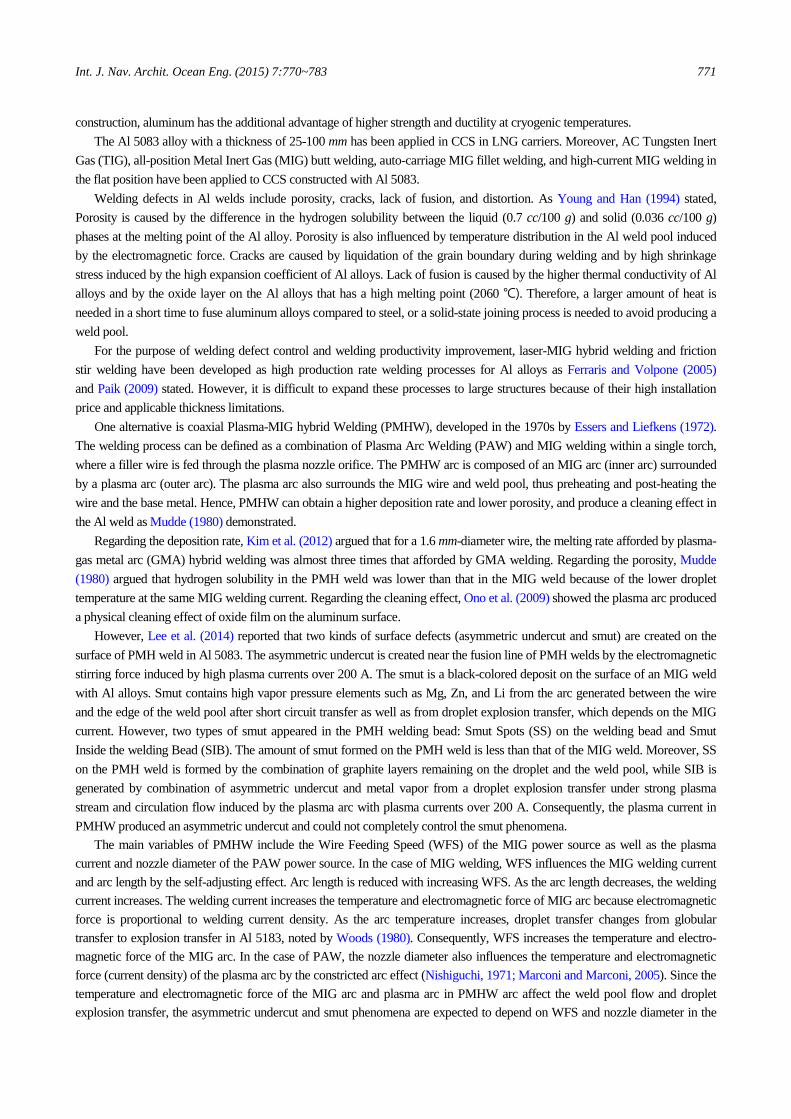
Fig. 13 shows a comparison of the welding condition areas between the smut type and metal transfer mode based on the results of this study. Compared to MIG and PMH welding as WFS increases, metal transfer mode changes from short-circuit transfer to globular explosion transfer in the case of MIG welding. However, in the case of PMH welding, metal transfer mode changes in the following order: explosion transfer, globular transfer, short-circuit transfer. To determine the reason for this, MIG output current, voltage and arc length of MIG and PMH welding were analyzed. Fig. 14 shows comparison of welding condition and droplet transfer mode as increasing wire feeding speed at constant plasma current 150 A. As shown in Fig. 14(a), MIG output current of MIG and PMH welding increases as WFS increase. In MIG welding, as WFS increases, both of MIG output current (a) and voltage (b) increase without change of arc length (c). Therefore, heat input to a droplet is increased, and a droplet starts to explode over WFS 10 m/min. However, in PMH welding, as WFS increases, MIG output current increase, whereas MIG output voltage and arc length decrease. Therefore, as WFS increases, a droplet is not sufficient to be heated up to the temperature of droplet explosion due to the lower MIG heat input and shorter arc length than MIG welding. However, all of MIG output current in PMHW is lower than one of MIG welding. Oliveira and Dutra (2007) reported that MIG output current in PMHW decreases as temperature of welding wire increase by preheat effect of plasma arc. As the temperature of the metal wire increases, the electrical resistivity of it increases. Therefore, MIG output current in PMHW is decreased by Ohm’s law.
Fig. 13 Comparison of welding condition by type of smut and mode of metal transfer.
Fig. 14 Comparison of MIG output result by MIG and PMH welding process with
changing wire feeding speed at constant plasma current 150 A.

Int. J. Nav. Archit. Ocean Eng. (2015) 7:770~783 779
The SOB is generated by in-flight explosion at 5 m/min and short circuit transfer over 10 m/min, while SIB was created by droplet explosion at plasma currents over 200 A in all WFS conditions. The SS was generated in the stable globular transfer condition without short circuit and explosion transfer. However, SS was not formed in high plasma currents and WFS con-ditions because of the removal of the carbon lubricant. As shown in Fig. 15, the SS was reduced by evaporation of the carbon lubricant on the droplet during transfer. Carbon lubricants from the welding wire gather in the center of the droplet as shown in Fig. 15(a). The size of the lubricant shrinks over time. Based on this result, even in the case where WFS was 5 m/min with a low MIG welding current, the duration of droplet transfer was long, and the droplet was sufficiently heated by the plasma arc. Thus, as the plasma current increased, the temperature of the droplet increased, and the carbon lubricant on the droplet was reduced by evaporation. On the other hand, when WFS was 20 m/min, the droplet transfer time occurred so quickly that the droplet was not sufficiently heated by the plasma arc. Instead, the temperature of the MIG arc increased as the MIG current increased through the self-adjusting effect (Lancaster, 1986). Therefore, SS was not formed in high plasma currents and WFS conditions because of the removal of the carbon lubricant.
Fig. 15 Evaporation of carbon lubricant on a droplet of PMHW using successive high
speed camera image at plasma current 200 A and WFS 15 m/min.
Effect of nozzle diameter on surface defects
Based on Fig. 13, to completely control smut formation, no droplet explosion and no carbon lubricant on the droplet can occur. To prevent droplet explosion, it is necessary to the lower droplet temperature by reducing the temperature of the PMHW arc. To prevent carbon lubricant on the droplet, it is necessary to increase the arc exposure time of the droplet in the PMHW arc. In other words, the droplet rate should be decreased by control of the magnetic pinch force and plasma stream in PMHW arc. The droplet rate is the total number of droplets transferred per second (Lancaster, 1986). According to Nishiguchi and Tashiro’s study (1970), the temperature and current density of the plasma arc decrease as the nozzle diameter increased. Moreover, the magnetic pinch force and plasma stream is proportional to the current density of the arc. It is expected that the low droplet temperature and droplet rate could be obtained by controlling the nozzle diameter. Therefore, the effect of nozzle diameter on surface defects of Al PMH welds was investigated.
Fig. 16 and 17 show the bead surface and transverse cross-sections of PMH welds using a nozzle diameter of 12 mm as the plasma current changed at constant WFS of 10 m/min and 20 m/min, respectively. The asymmetric undercut was not created under any welding conditions because of the low electromagnetic stirring force induced by the low plasma current density as the nozzle diameter increased. Consequently, the asymmetric undercut can be controlled by the nozzle diameter.
In the case where the WFS was 10 m/min, SOB and SS were created on the right side of the base metal and on the welding bead at plasma current of 100 A-250 A as shown in Fig. 16(a) to (c). In the case where the WFS was 20 m/min as shown in Fig. 17, only SOB was created on the left side of the base metal at a plasma current of 100 A. At plasma currents of 200 A and 250 A, smut was not created on the welding bead.
Smut created under each welding condition with a nozzle diameter of 12 mm is described in Table 3. Compared to Table 2, which showed the case where the nozzle diameter was 9 mm, SIB was not created because the in-flight explosion and asym-metric undercut did not occur under any welding condition. That means the temperature of a droplet in the PMHW with nozzle diameter of 12 mm is below the droplet temperature of 1560°C during the transfer. Moreover, smut was not created when the plasma current was 150 A to 250 A at a WFS of 15 m/min and 20 m/min.

780 Int. J. Nav. Archit. Ocean Eng. (2015) 7:770~783
Fig. 16 Bead surface and transverse cross-section of Plasma-MIG hybrid welding with increasing plasma current
(wire feeding speed: 10 m/min, Nozzle diameter: 12 mm). (a), (d): Bead surface and transverse cross-section at plasma current 100 A; (b), (e): Bead surface and transverse cross-section at plasma current 200 A; (c), (f): Bead surface and transverse cross-section at plasma current 250 A.
Fig. 17 Bead surface and transverse cross-section of Plasma-MIG hybrid welding with increasing plasma current
(wire feeding speed: 20 m/min, Nozzle diameter: 12 mm). (a), (d): Bead surface and transverse cross-section at plasma current 100 A; (b), (e): Bead surface and transverse cross-section at plasma current 200 A; (c), (f): Bead surface and transverse cross-section at plasma current 250 A.
Table 3 Classification of Smut on Al 5083 bead of PMH welding conditions (Nozzle Dia.: 12 mm).
Wire feeding speed (m/min)
Plasma current (A)
50 100 150 200 250
5 SOB SOB SOB SOB SOB / SS
10 SOB SOB / SS SOB / SS SOB / SS SOB / SS
15 SOB SOB / SS SOB / SS No formation No formation
20 SOB SOB / SS No formation No formation No formation
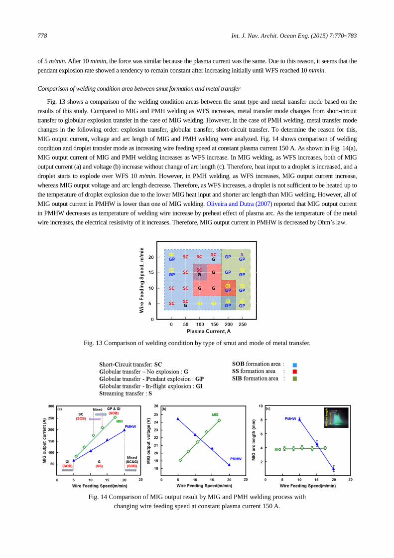
Fig. 18 shows comparison of droplet rate with 9 mm and 12 mm nozzle diameters. The droplet rate was lower when the
nozzle diameter was 12 mm than when the nozzle diameter was 9 mm. Therefore, in the PMHW arc, a long droplet exposure time was obtained by using 12 mm nozzle diameter.
Int. J. Nav. Archit. Ocean Eng. (2015) 7:770~783 781
(a) Time of droplet transfer into weld pool at plasma current 200 A and WFS 15 m/min.
(b) Droplet rate as a function of (c) Droplet rate as a function of wire plasma current (WFS: 15 m/min). feeding speed (Plasma current: 150 A).
Fig. 18 Comparison of droplet rate with changing the nozzle of Dia. 9 mm and 12 mm.
CONCLUSION
For controlling the surface defect formation, the effect of the wire feeding speed and nozzle diameter on surface defects of Al PMH welds was investigated using the arc phenomena with high-speed imaging and metallurgical analysis. The results are summarized as follows: 1) As the WFS increased, the size of the undercut also decreases because the amount of the welding wire in the welding pool
increased. Moreover, the WFS increase tends to reduce the amount and formation area of smut. 2) At the constant plasma current of 150 A, as the wire feeding speed increased, two types of smut were created on the PMH
weld: SOB and SS on the welding bead. At 5 m/min, SOB is generated by a combination of the in-flight explosion near the plasma nozzle, the insufficient magnetic pinch force, and the plasma stream of the PMHW arc. However, SOB is generated by a short circuit transfer over 10 m/min.
3) The SS on the PMH weld is formed by the carbon lubricant on the droplet and by the weld pool at a stable globular transfer without any spattering. However, as the plasma current or wire feeding speed increased, the carbon lubricant on the droplet reduced enough for SS formation to occur through carbon lubricant evaporation.
4) At the constant plasma current of 250 A, as the wire feeding speed increased, one type of smut was created on the PMH weld: SIB. Moreover, the amount of SIB decreases due to the decreasing in-flight explosion rate.
5) As the nozzle diameter increased, the asymmetric undercut was not created in any of welding conditions using low electromagnetic stirring force induced low plasma current density. Moreover, smut was not formed in high plasma currents and WFS conditions because no in-flight explosion occurred and because of the lower droplet rate than the case where the nozzle diameter was 9 mm.
6) Consequently, surface defects can be completely controlled by controlling the nozzle diameter.

782 Int. J. Nav. Archit. Ocean Eng. (2015) 7:770~783
ACKNOWLEDGMENT
This research was supported by the Global Frontier Program through the Global Frontier Hybrid Interface Materials (GFHIM) of the National Research Foundation of Korea (NRF) funded by the Ministry of Science, ICT & Future Planning (2013M3A6B1078874).
REFERENCES
Anderson, B.E. and Alcotec, 1990. Lubricated aluminum weld wire and process for spooling it. U.S. Pat. 4913927. ExxonMobil, 2014. 2014 outlook for energy a view to 2040. Available at: < http://corporate.exxonmobil.com/en/energy/
energy-outlook > [Accessed 12 August 2014]. Essers, W.G. and Liefkens, A.C., 1972. Plasma-MIG welding developed by Philips. Machinery and Production Engineer-
ing, 1, pp.632-633. Ferraris, S. and Volpone, L.M., 2005. Aluminium alloys in third millennium shipbuilding: materials, technologies, perspec-
tives. The Fifth International Forum on Aluminum Ships, Tokyo, Japan, 11-13 October 2005, pp.1-11. Kazuyuki, M., 1973. Problems about thick plate welding of aluminium in LNG carrier(in Japanese). Bulletin of the Society
of Naval Architects of Japan, 530, pp.414-424. Kim, C.H., Ahn, Y.N. and Lee, K.B., 2012. Droplet transfer during conventional gas metal arc and plasma-gas metal arc
hybrid welding Al 5183 filler metal. Current applied Physics, 12, pp.S178-S183. Kim, C.H., Ahn, Y.N., Choi, J.K. and Rhee, S.H., 2010. Process evaluation of plasma-GMA welding for Al 5052 and 6061
Alloy (in Korean). Journal of KWJS, 28(6), pp.58-62. Lancaster, J.F., 1986. The physics of welding. 2nd ed. Oxford: Oxford Pergamon. Lee, H.K., Park, S.H., Chun, K.S., Kim, J.Y., Chung, H.T. and Kang, C.Y., 2014. Mechanism of smut reduction in welding
Al-Mg alloys using Plasma-MIG hybrid welding. proceedings of the 3rd International Symposium on Visualization in Joining & Welding Science through Advanced Measurements and Simulation (Visual-JW 2014), Joining and Welding Research Institute, Osaka, Japan, 26-28 November 2014, pp.50.
Lee, J.S., You, W.H., Yoo, C.H., Kim, K.S. and Kim, Y.I., 2013. An experimental study on fatigue performance of cryogenic metallic materials for IMO type B tank. International Journal of Naval Architecture Ocean Engineering, 5(4), pp.580-597.
Marconi, M. and Marconi, B., 2005. Powder plasma arc welding on thick walled pipes. Welding in the world, 49, pp.249-264.
Malinowski-brodnicka, M., Ouden, G.D. and Vink, W.J.P., 1990. Effect of electromagnetic stirring on GTA welds in austenitic stainless steel. Welding Journal, February, p52-s-59-s.
Mudde, A., 1980. Plasma-mig offers benefits for welding aluminum. Welding and Metal Fabrication, October 1980, pp. 521-526.
Nishiguchi, K., 1971. Plasma arc welding. Journal of the Japan Welding Society, 40(12), pp.1206-1219. Nishiguchi, K. and Tashiro, K., 1970. Series arcing in plasma arc welding. Journal of Japan Welding Society, 39(4), pp.
206-279. Ono, K., Liu, Z., Era, T., Uezono, T., Ueyama, T., Tanaka, M. and Nakata, K., 2009. Development of a plasma MIG weld-
ing system for aluminium. Welding International, 23(11), pp.805-809. Osaka University, 2012. Ar-MIG welding with ionizing plasma, project (in Japanese), brochure of NEDO project, R&D
project on fundamental technology for steel materials with enhanced strength and functionality. Japan International Welding Show 2012, Osaka, 13 April 2012, pp.1-4.
Oliveira, M.A., and Dutra, J.C., 2007, Electrical model for the plasma-MIG hybrid welding process. Welding and cutting, 6, pp.324-328.
Paik, J.K., 2009. Mechanical properties of friction stir welded aluminum alloys 5083 and 5383. International Journal of Naval Architecture Ocean Engineering, 1(1), pp.39-49.

Int. J. Nav. Archit. Ocean Eng. (2015) 7:770~783 783
Schnick, M., Füssel, U. and Zschetzsche, J., 2006. Simulation of plasma and shielding gas flows in welding and cutting arcs with ansys CFX. International Scientific Colloquium on ‘Modelling for Material Processing’, Riga, Latvia, 8-9 June 2006, pp.143-148.
Tanaka, M. and Tsujimura, Y., 2012. Visualization of metal vapor behavior in TIG welding: Visualization of phenomena of welding arc by imaging spectroscopy. Quarterly Journal of the Japan Welding Society, 30(2), pp.164-170.
Ton, H., 1975. Physical properties of the plasma-MIG welding arc. Journal of Physics D: Applied Physics, 8, pp.922-933.
Woods, R.A., 1980. Metal transfer in aluminum alloys. Welding Journal, February, pp.59-s-66-s. Youn, K.H. and Han, Y.S., 1994. Gas metal arc welding of aluminum alloy (in Korean). Journal of KJWS, 12(1), pp.
16-27.


![Platelet-rich plasma for the treatment of bone defects: … reported to enhance osteoblastic activity and favour im-plant integration [ 9, 10]. Platelet-rich plasma (PRP) is emerging](https://img.pdfslide.us/doc/110x75/5b0810917f8b9a992a8bc0d8/platelet-rich-plasma-for-the-treatment-of-bone-defects-reported-to-enhance-osteoblastic.jpg)