Embed Size (px)
Citation preview
Control of Separation on the Flap of a Three-Element
High-Lift Configuration
B. Gunther∗ and Frank Thiele†
Berlin University of Technology, D–10623 Berlin, Germany
R. Petz‡ and W. Nitsche §
Berlin University of Technology, D–10587 Berlin, Germany
J. Sahner¶ , T. Weinkauf‖ and H.-C. Hege∗∗
Zuse Institute Berlin, D–14195 Berlin, Germany
This paper describes a joint experimental and numerical investigation of the controlof the flow over the flap of a three-element high-lift configuration by means of periodicexcitation. At Reynolds numbers between 0.3 × 10⁶ and 1 × 10⁶ the flow is influenced byperiodic blowing or periodic blowing/suction through slots near the flap leading edge. Thedelay of flow separation by periodic vertical excitation could be identified in the experimentsas well as numerical simulations based on the Unsteady Reynolds-averaged Navier-Stokesequations (URANS). As a result, the mean aerodynamic lift of this practically relevantwing configuration could be significantly enhanced. By investigating different excitationfrequencies and intensities optimum control parameters could be found. The behaviour ofthe aerodynamic forces with varying flap deflection angle are measured on a finite sweptwing. Scientific visualisation of the numerical simulations of an infinite swept wing allowsa detailed analysis of the structures in this complex flow field and the effect of flow controlon these.
Nomenclature
c, ck clean chord length, flap length (ck = 0.254c)cL, cLmax lift coefficient, maximum lift coefficient
Cµ momentum coefficient Cµ = 2Hc
(ua
u∞
)2
f , F+ frequency of periodic excitation, non-dimensional excitation frequency F+ = f ck/u∞H slot width (H = 0.00186ck)Rec Reynolds number based on chord lengthSt Strouhal number based on flap lengthu∞ inflow velocityua, uexc amplitude velocity of the perturbation in the slot, excitation velocityα, δf , δs angle of attack of the main airfoil, flap deflection angle, slat deflection angle∆t time step sizeΦ sweep angle
∗Research Associate, Institute of Fluid Mechanics and Engineering Acoustics, Muller–Breslau–Straße 8,[email protected], +49-30-314-23146, AIAA Student Member.
†Professor, [email protected], AIAA Member.‡Research Associate, Institute of Aeronautics and Astronautics, Marchstraße 12, [email protected], AIAA StudentMember.
§Professor, [email protected] , AIAA Member.¶Research Associate, Department Visualization and Data Analysis, Takustraße 7, [email protected].‖Research Associate, Department Visualization and Data Analysis, Takustraße 7, [email protected].∗∗Professor, [email protected].
1 of 15
American Institute of Aeronautics and Astronautics
45th AIAA Aerospace Sciences Meeting and Exhibit8 - 11 January 2007, Reno, Nevada
AIAA 2007-265
Copyright © 2007 by Bert Günther, Frank Thiele, Ralf Petz, Wolfgang Nitsche, Jan Sahner, Tino Weinkauf, Hans-Christian Hege. Published by the American Institute of Aeronautics and Astronautics, Inc., with permission.
I. Introduction
The wings of commercial aircrafts must generate a tremendous amount of lift during take-off and landingin order to reduce ground speeds and runway lengths. Instead of incorporating complex, heavy and expensivemulti-element high lift devices, single flaps without slats are desirable. Such flaps can however only be appliedif flow separation at high flap angles can be avoided. Experimental investigations1 as well as numericalsimulations2 have shown that flap separation can be significantly delayed by periodic excitation near the flapleading edge in the case of low and high Reynolds numbers3 and the lift can be enhanced.
In the past a large number of experimental and numerical studies showed the general effectiveness offlow control for single airfoils (e.g.4–7). In most of them, leading edge suction is applied either for transitiondelay8 or to affect the separation.9,10 Other studies employ jet flaps for lift increase and manoeuvring.11
Unfortunately, most of the earlier control techniques considered have shown little effectiveness.
In further investigations oscillatory suction and blowing was found to be much more efficient with respectto lift than steady blowing. The process becomes very efficient if the excitation frequencies correspond to themost unstable frequencies of the free shear layer, generating arrays of spanwise vortices that are convecteddownstream and continue to mix across the shear layer. Suction and blowing can be applied tangential tothe airfoil surface,12 perpendicular13,14 or with cyclic vortical oscillation. In order to create an effective andefficient control method previous studies have been primarily focused on the parameters of the excitationapparatus itself. Overviews are given by Wygnanski and Gad-el-Hak.15,16
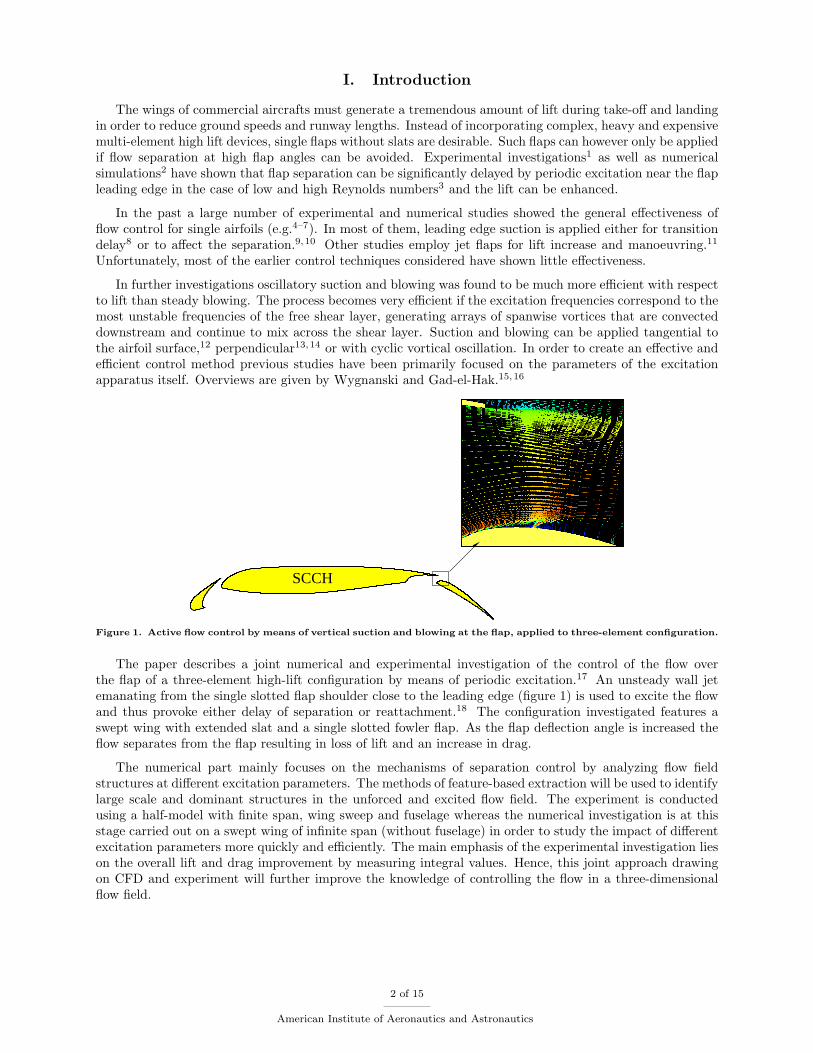
SCCH
Figure 1. Active flow control by means of vertical suction and blowing at the flap, applied to three-element configuration.
The paper describes a joint numerical and experimental investigation of the control of the flow overthe flap of a three-element high-lift configuration by means of periodic excitation.17 An unsteady wall jetemanating from the single slotted flap shoulder close to the leading edge (figure 1) is used to excite the flowand thus provoke either delay of separation or reattachment.18 The configuration investigated features aswept wing with extended slat and a single slotted fowler flap. As the flap deflection angle is increased theflow separates from the flap resulting in loss of lift and an increase in drag.
The numerical part mainly focuses on the mechanisms of separation control by analyzing flow fieldstructures at different excitation parameters. The methods of feature-based extraction will be used to identifylarge scale and dominant structures in the unforced and excited flow field. The experiment is conductedusing a half-model with finite span, wing sweep and fuselage whereas the numerical investigation is at thisstage carried out on a swept wing of infinite span (without fuselage) in order to study the impact of differentexcitation parameters more quickly and efficiently. The main emphasis of the experimental investigation lieson the overall lift and drag improvement by measuring integral values. Hence, this joint approach drawingon CFD and experiment will further improve the knowledge of controlling the flow in a three-dimensionalflow field.
2 of 15
American Institute of Aeronautics and Astronautics
II. Numerical Method
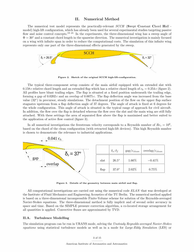
The numerical test model represents the practically-relevant SCCH (Swept Constant Chord Half -model) high-lift configuration, which has already been used for several experimental studies targeting passiveflow and noise control concepts.19–21 In the experiments, the three-dimensional wing has a sweep angle ofΦ = 30◦ and a constant chord length in the spanwise direction. The numerical investigation is mainly focusedon a wing with infinite span in order to reduce the computational costs. The simulation of this infinite wingrepresents only one part of the three-dimensional effects generated by the sweep.
Sδ = 26.5° δ = 32°F
SCCH
Figure 2. Sketch of the original SCCH high-lift-configuration.
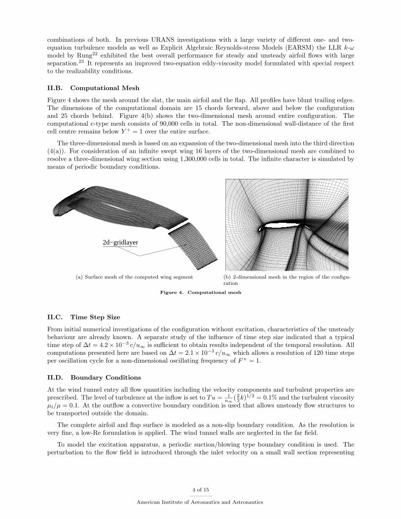
The typical three-component setup consists of the main airfoil equipped with an extended slat with0.158 c relative chord length and an extended flap which has a relative chord length of ck = 0.254 c (figure 2).All profiles have blunt trailing edges. The flap is situated at a fixed position underneath the trailing edge,forming a gap of 0.0202 c and an overlap of 0.0075 c. The flap deflection angle was increased from the basevalue (32◦) in precursor, steady simulations. The detachment position of the flow on the upper flap surfacestagnates upstream from a flap deflection angle of 37 degrees. The angle of attack is fixed at 6 degrees forthe whole configuration. This angle of attack is situated in the typical range of approach for civil aircraft.In addition, the flow over the flap is detached whereas the flow over the slat and the main wing are still fullyattached. With these settings the area of separated flow above the flap is maximised and better suited tothe application of active flow control (figure 3).
In all numerical investigations the freestream velocity corresponds to a Reynolds number of Rec = 106,based on the chord of the clean configuration (with retracted high-lift devices). This high Reynolds numberis chosen to demonstrate the relevance to industrial applications.
δ = 37°F
k0.041 c
overlap
gap
δs; δf gap/cclean overlap/cclean
slat 26.5◦ 1.66% −0.41%
flap 37.0◦ 2.02% 0.75%
Figure 3. Details of the geometry between main airfoil and flap.
All computational investigations are carried out using the numerical code ELAN that was developed atthe Institute of Fluid Mechanics and Engineering Acoustics of the TU Berlin. The numerical method appliedis based on a three-dimensional incompressible Finite-Volume scheme for solution of the Reynolds-averagedNavier-Stokes equations. The three-dimensional method is fully implicit and of second order accuracy inspace and time. Based on the SIMPLE pressure correction algorithm, a co-located storage arrangement forall quantities is applied. Convective fluxes are approximated by TVD.
II.A. Turbulence Modelling
The simulation program can be run in URANS mode, solving the Unsteady Reynolds-averaged Navier-Stokesequations using statistical turbulence models as well as in a mode for Large-Eddy Simulation (LES) or
3 of 15
American Institute of Aeronautics and Astronautics
combinations of both. In previous URANS investigations with a large variety of different one- and two-equation turbulence models as well as Explicit Algebraic Reynolds-stress Models (EARSM) the LLR k-ωmodel by Rung22 exhibited the best overall performance for steady and unsteady airfoil flows with largeseparation.23 It represents an improved two-equation eddy-viscosity model formulated with special respectto the realizability conditions.
II.B. Computational Mesh
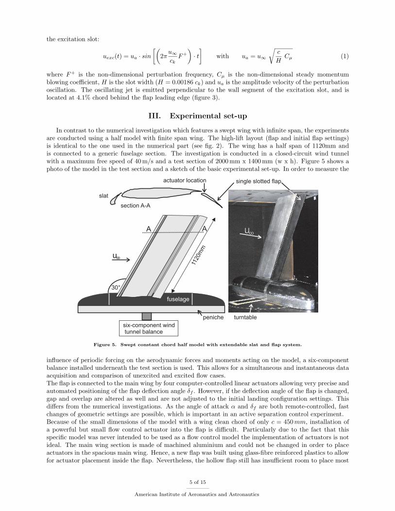
Figure 4 shows the mesh around the slat, the main airfoil and the flap. All profiles have blunt trailing edges.The dimensions of the computational domain are 15 chords forward, above and below the configurationand 25 chords behind. Figure 4(b) shows the two-dimensional mesh around entire configuration. Thecomputational c-type mesh consists of 90,000 cells in total. The non-dimensional wall-distance of the firstcell centre remains below Y + = 1 over the entire surface.
The three-dimensional mesh is based on an expansion of the two-dimensional mesh into the third direction(4(a)). For consideration of an infinite swept wing 16 layers of the two-dimensional mesh are combined toresolve a three-dimensional wing section using 1,300,000 cells in total. The infinite character is simulated bymeans of periodic boundary conditions.
2d−gridlayer
(a) Surface mesh of the computed wing segment (b) 2-dimensional mesh in the region of the configu-ration
Figure 4. Computational mesh
II.C. Time Step Size
From initial numerical investigations of the configuration without excitation, characteristics of the unsteadybehaviour are already known. A separate study of the influence of time step size indicated that a typicaltime step of ∆t = 4.2× 10⁻³ c/u∞ is sufficient to obtain results independent of the temporal resolution. Allcomputations presented here are based on ∆t = 2.1× 10⁻³ c/u∞ which allows a resolution of 120 time stepsper oscillation cycle for a non-dimensional oscillating frequency of F+ = 1.
II.D. Boundary Conditions
At the wind tunnel entry all flow quantities including the velocity components and turbulent properties areprescribed. The level of turbulence at the inflow is set to Tu = 1
u∞( 23k)1/2 = 0.1% and the turbulent viscosity
µt/µ = 0.1. At the outflow a convective boundary condition is used that allows unsteady flow structures tobe transported outside the domain.
The complete airfoil and flap surface is modeled as a non-slip boundary condition. As the resolution isvery fine, a low-Re formulation is applied. The wind tunnel walls are neglected in the far field.
To model the excitation apparatus, a periodic suction/blowing type boundary condition is used. Theperturbation to the flow field is introduced through the inlet velocity on a small wall section representing
4 of 15
American Institute of Aeronautics and Astronautics
the excitation slot:
uexc(t) = ua · sin[(
2πu∞ck
F+
)· t
]with ua = u∞
√c
HCµ (1)
where F+ is the non-dimensional perturbation frequency, Cµ is the non-dimensional steady momentumblowing coefficient, H is the slot width (H = 0.00186 ck) and ua is the amplitude velocity of the perturbationoscillation. The oscillating jet is emitted perpendicular to the wall segment of the excitation slot, and islocated at 4.1% chord behind the flap leading edge (figure 3).
III. Experimental set-up
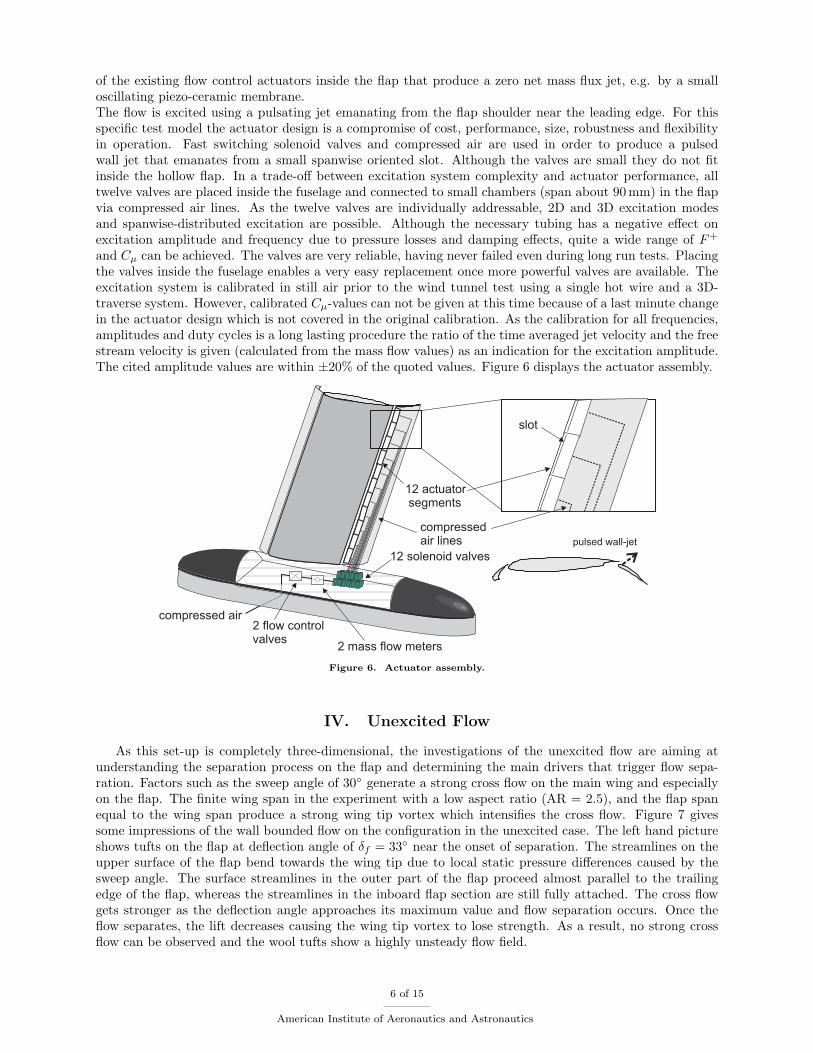
In contrast to the numerical investigation which features a swept wing with infinite span, the experimentsare conducted using a half model with finite span wing. The high-lift layout (flap and initial flap settings)is identical to the one used in the numerical part (see fig. 2). The wing has a half span of 1120mm andis connected to a generic fuselage section. The investigation is conducted in a closed-circuit wind tunnelwith a maximum free speed of 40 m/s and a test section of 2000mm x 1400 mm (w x h). Figure 5 shows aphoto of the model in the test section and a sketch of the basic experimental set-up. In order to measure the
Figure 5. Swept constant chord half model with extendable slat and flap system.
influence of periodic forcing on the aerodynamic forces and moments acting on the model, a six-componentbalance installed underneath the test section is used. This allows for a simultaneous and instantaneous dataacquisition and comparison of unexcited and excited flow cases.The flap is connected to the main wing by four computer-controlled linear actuators allowing very precise andautomated positioning of the flap deflection angle δf . However, if the deflection angle of the flap is changed,gap and overlap are altered as well and are not adjusted to the initial landing configuration settings. Thisdiffers from the numerical investigations. As the angle of attack α and δf are both remote-controlled, fastchanges of geometric settings are possible, which is important in an active separation control experiment.Because of the small dimensions of the model with a wing clean chord of only c = 450mm, installation ofa powerful but small flow control actuator into the flap is difficult. Particularly due to the fact that thisspecific model was never intended to be used as a flow control model the implementation of actuators is notideal. The main wing section is made of machined aluminium and could not be changed in order to placeactuators in the spacious main wing. Hence, a new flap was built using glass-fibre reinforced plastics to allowfor actuator placement inside the flap. Nevertheless, the hollow flap still has insufficient room to place most
5 of 15
American Institute of Aeronautics and Astronautics
of the existing flow control actuators inside the flap that produce a zero net mass flux jet, e.g. by a smalloscillating piezo-ceramic membrane.The flow is excited using a pulsating jet emanating from the flap shoulder near the leading edge. For thisspecific test model the actuator design is a compromise of cost, performance, size, robustness and flexibilityin operation. Fast switching solenoid valves and compressed air are used in order to produce a pulsedwall jet that emanates from a small spanwise oriented slot. Although the valves are small they do not fitinside the hollow flap. In a trade-off between excitation system complexity and actuator performance, alltwelve valves are placed inside the fuselage and connected to small chambers (span about 90 mm) in the flapvia compressed air lines. As the twelve valves are individually addressable, 2D and 3D excitation modesand spanwise-distributed excitation are possible. Although the necessary tubing has a negative effect onexcitation amplitude and frequency due to pressure losses and damping effects, quite a wide range of F+
and Cµ can be achieved. The valves are very reliable, having never failed even during long run tests. Placingthe valves inside the fuselage enables a very easy replacement once more powerful valves are available. Theexcitation system is calibrated in still air prior to the wind tunnel test using a single hot wire and a 3D-traverse system. However, calibrated Cµ-values can not be given at this time because of a last minute changein the actuator design which is not covered in the original calibration. As the calibration for all frequencies,amplitudes and duty cycles is a long lasting procedure the ratio of the time averaged jet velocity and the freestream velocity is given (calculated from the mass flow values) as an indication for the excitation amplitude.The cited amplitude values are within ±20% of the quoted values. Figure 6 displays the actuator assembly.
Figure 6. Actuator assembly.
IV. Unexcited Flow
As this set-up is completely three-dimensional, the investigations of the unexcited flow are aiming atunderstanding the separation process on the flap and determining the main drivers that trigger flow sepa-ration. Factors such as the sweep angle of 30◦ generate a strong cross flow on the main wing and especiallyon the flap. The finite wing span in the experiment with a low aspect ratio (AR = 2.5), and the flap spanequal to the wing span produce a strong wing tip vortex which intensifies the cross flow. Figure 7 givessome impressions of the wall bounded flow on the configuration in the unexcited case. The left hand pictureshows tufts on the flap at deflection angle of δf = 33◦ near the onset of separation. The streamlines on theupper surface of the flap bend towards the wing tip due to local static pressure differences caused by thesweep angle. The surface streamlines in the outer part of the flap proceed almost parallel to the trailingedge of the flap, whereas the streamlines in the inboard flap section are still fully attached. The cross flowgets stronger as the deflection angle approaches its maximum value and flow separation occurs. Once theflow separates, the lift decreases causing the wing tip vortex to lose strength. As a result, no strong crossflow can be observed and the wool tufts show a highly unsteady flow field.
6 of 15
American Institute of Aeronautics and Astronautics
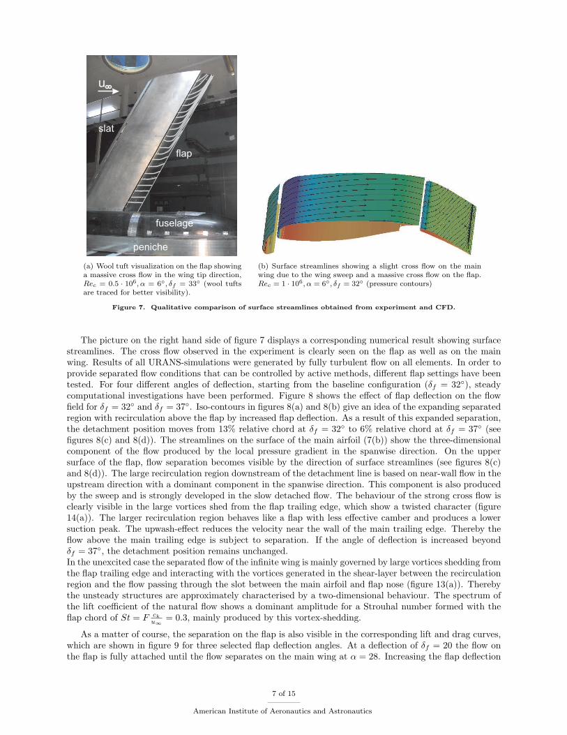
(a) Wool tuft visualization on the flap showinga massive cross flow in the wing tip direction,Rec = 0.5 · 106, α = 6◦, δf = 33◦ (wool tuftsare traced for better visibility).
(b) Surface streamlines showing a slight cross flow on the mainwing due to the wing sweep and a massive cross flow on the flap.Rec = 1 · 106, α = 6◦, δf = 32◦ (pressure contours)
Figure 7. Qualitative comparison of surface streamlines obtained from experiment and CFD.
The picture on the right hand side of figure 7 displays a corresponding numerical result showing surfacestreamlines. The cross flow observed in the experiment is clearly seen on the flap as well as on the mainwing. Results of all URANS-simulations were generated by fully turbulent flow on all elements. In order toprovide separated flow conditions that can be controlled by active methods, different flap settings have beentested. For four different angles of deflection, starting from the baseline configuration (δf = 32◦), steadycomputational investigations have been performed. Figure 8 shows the effect of flap deflection on the flowfield for δf = 32◦ and δf = 37◦. Iso-contours in figures 8(a) and 8(b) give an idea of the expanding separatedregion with recirculation above the flap by increased flap deflection. As a result of this expanded separation,the detachment position moves from 13% relative chord at δf = 32◦ to 6% relative chord at δf = 37◦ (seefigures 8(c) and 8(d)). The streamlines on the surface of the main airfoil (7(b)) show the three-dimensionalcomponent of the flow produced by the local pressure gradient in the spanwise direction. On the uppersurface of the flap, flow separation becomes visible by the direction of surface streamlines (see figures 8(c)and 8(d)). The large recirculation region downstream of the detachment line is based on near-wall flow in theupstream direction with a dominant component in the spanwise direction. This component is also producedby the sweep and is strongly developed in the slow detached flow. The behaviour of the strong cross flow isclearly visible in the large vortices shed from the flap trailing edge, which show a twisted character (figure14(a)). The larger recirculation region behaves like a flap with less effective camber and produces a lowersuction peak. The upwash-effect reduces the velocity near the wall of the main trailing edge. Thereby theflow above the main trailing edge is subject to separation. If the angle of deflection is increased beyondδf = 37◦, the detachment position remains unchanged.In the unexcited case the separated flow of the infinite wing is mainly governed by large vortices shedding fromthe flap trailing edge and interacting with the vortices generated in the shear-layer between the recirculationregion and the flow passing through the slot between the main airfoil and flap nose (figure 13(a)). Therebythe unsteady structures are approximately characterised by a two-dimensional behaviour. The spectrum ofthe lift coefficient of the natural flow shows a dominant amplitude for a Strouhal number formed with theflap chord of St = F ck
u∞= 0.3, mainly produced by this vortex-shedding.
As a matter of course, the separation on the flap is also visible in the corresponding lift and drag curves,which are shown in figure 9 for three selected flap deflection angles. At a deflection of δf = 20 the flow onthe flap is fully attached until the flow separates on the main wing at α = 28. Increasing the flap deflection
7 of 15
American Institute of Aeronautics and Astronautics
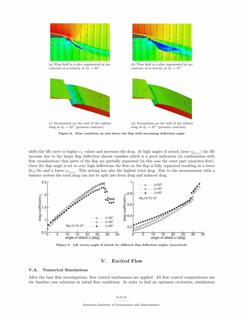
(a) Flow field in a slice represented by iso-contours of u-velocity at δF = 32◦
(b) Flow field in a slice represented by iso-contours of u-velocity at δF = 37◦
(c) Streamlines on the wall of the infinitewing at δF = 32◦ (pressure contours)
(d) Streamlines on the wall of the infinitewing at δF = 37◦ (pressure contours)
Figure 8. Flow condition on and above the flap with increasing deflection angle
shifts the lift curve to higher cL values and increases the drag. At high angles of attack (near cLmax) the lift
increase due to the larger flap deflection almost vanishes which is a good indication (in combination withflow visualization) that parts of the flap are partially separated (in this case the outer part separates first).Once the flap angle is set to very high deflections the flow on the flap is fully separated resulting in a lower∂cL/∂α and a lower cLmax . This setting has also the highest total drag. Due to the measurement with abalance system the total drag can not be split into form drag and induced drag.
Figure 9. Lift versus angle of attack for different flap deflection angles (unexcited)
V. Excited Flow
V.A. Numerical Simulations
After the base flow investigations, flow control mechanisms are applied. All flow control computations usethe baseline case solutions as initial flow conditions. In order to find an optimum excitation, simulations
8 of 15
American Institute of Aeronautics and Astronautics
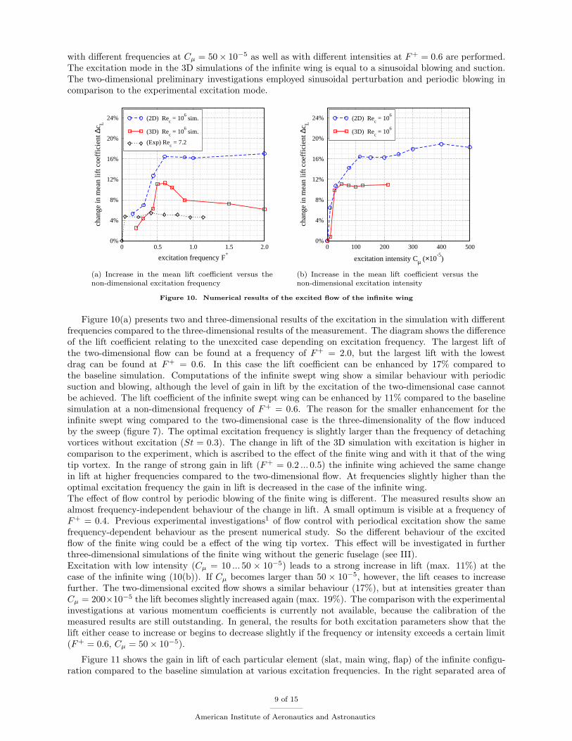
with different frequencies at Cµ = 50× 10−5 as well as with different intensities at F+ = 0.6 are performed.The excitation mode in the 3D simulations of the infinite wing is equal to a sinusoidal blowing and suction.The two-dimensional preliminary investigations employed sinusoidal perturbation and periodic blowing incomparison to the experimental excitation mode.
0 0.5 1.0 1.5 2.0
excitation frequency F+
0%
4%
8%
12%
16%
20%
24%
chan
ge in
mea
n lif
t coe
ffic
ient
∆c L
(2D) Rec = 10
6 sim.
(3D) Rec = 10
6 sim.
(Exp) Rec = 7.2
(a) Increase in the mean lift coefficient versus thenon-dimensional excitation frequency
0 100 200 300 400 500
excitation intensity Cµ (×10-5
)
0%
4%
8%
12%
16%
20%
24%
chan
ge in
mea
n lif
t coe
ffic
ient
∆c L
(2D) Rec = 10
6
(3D) Rec = 10
6
(b) Increase in the mean lift coefficient versus thenon-dimensional excitation intensity
Figure 10. Numerical results of the excited flow of the infinite wing
Figure 10(a) presents two and three-dimensional results of the excitation in the simulation with differentfrequencies compared to the three-dimensional results of the measurement. The diagram shows the differenceof the lift coefficient relating to the unexcited case depending on excitation frequency. The largest lift ofthe two-dimensional flow can be found at a frequency of F+ = 2.0, but the largest lift with the lowestdrag can be found at F+ = 0.6. In this case the lift coefficient can be enhanced by 17% compared tothe baseline simulation. Computations of the infinite swept wing show a similar behaviour with periodicsuction and blowing, although the level of gain in lift by the excitation of the two-dimensional case cannotbe achieved. The lift coefficient of the infinite swept wing can be enhanced by 11% compared to the baselinesimulation at a non-dimensional frequency of F+ = 0.6. The reason for the smaller enhancement for theinfinite swept wing compared to the two-dimensional case is the three-dimensionality of the flow inducedby the sweep (figure 7). The optimal excitation frequency is slightly larger than the frequency of detachingvortices without excitation (St = 0.3). The change in lift of the 3D simulation with excitation is higher incomparison to the experiment, which is ascribed to the effect of the finite wing and with it that of the wingtip vortex. In the range of strong gain in lift (F+ = 0.2 ... 0.5) the infinite wing achieved the same changein lift at higher frequencies compared to the two-dimensional flow. At frequencies slightly higher than theoptimal excitation frequency the gain in lift is decreased in the case of the infinite wing.The effect of flow control by periodic blowing of the finite wing is different. The measured results show analmost frequency-independent behaviour of the change in lift. A small optimum is visible at a frequency ofF+ = 0.4. Previous experimental investigations1 of flow control with periodical excitation show the samefrequency-dependent behaviour as the present numerical study. So the different behaviour of the excitedflow of the finite wing could be a effect of the wing tip vortex. This effect will be investigated in furtherthree-dimensional simulations of the finite wing without the generic fuselage (see III).Excitation with low intensity (Cµ = 10 ... 50 × 10−5) leads to a strong increase in lift (max. 11%) at thecase of the infinite wing (10(b)). If Cµ becomes larger than 50 × 10−5, however, the lift ceases to increasefurther. The two-dimensional excited flow shows a similar behaviour (17%), but at intensities greater thanCµ = 200×10−5 the lift becomes slightly increased again (max. 19%). The comparison with the experimentalinvestigations at various momentum coefficients is currently not available, because the calibration of themeasured results are still outstanding. In general, the results for both excitation parameters show that thelift either cease to increase or begins to decrease slightly if the frequency or intensity exceeds a certain limit(F+ = 0.6, Cµ = 50× 10−5).
Figure 11 shows the gain in lift of each particular element (slat, main wing, flap) of the infinite configu-ration compared to the baseline simulation at various excitation frequencies. In the right separated area of
9 of 15
American Institute of Aeronautics and Astronautics
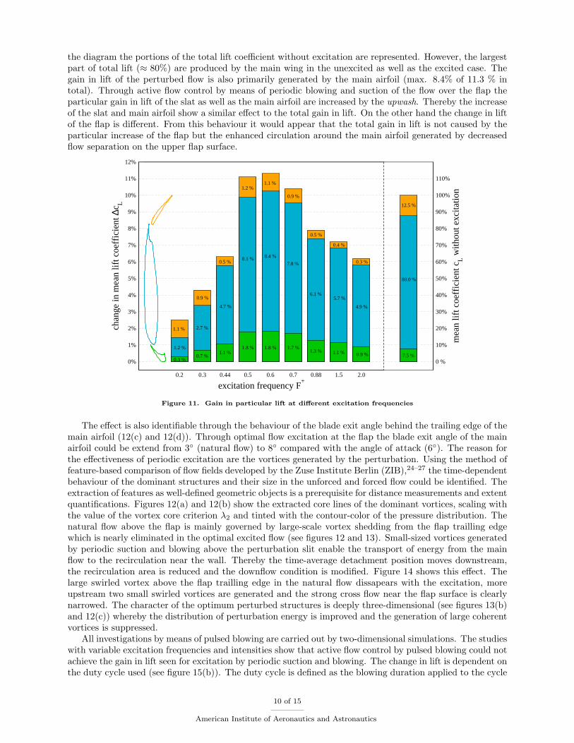
the diagram the portions of the total lift coefficient without excitation are represented. However, the largestpart of total lift (≈ 80%) are produced by the main wing in the unexcited as well as the excited case. Thegain in lift of the perturbed flow is also primarily generated by the main airfoil (max. 8.4% of 11.3 % intotal). Through active flow control by means of periodic blowing and suction of the flow over the flap theparticular gain in lift of the slat as well as the main airfoil are increased by the upwash. Thereby the increaseof the slat and main airfoil show a similar effect to the total gain in lift. On the other hand the change in liftof the flap is different. From this behaviour it would appear that the total gain in lift is not caused by theparticular increase of the flap but the enhanced circulation around the main airfoil generated by decreasedflow separation on the upper flap surface.
0.2 0.3 0.44 0.5 0.6 0.7 0.88 1.5 2.0
excitation frequency F+
0%
1%
2%
3%
4%
5%
6%
7%
8%
9%
10%
11%
12%
chan
ge in
mea
n lif
t coe
ffic
ient
∆c L
0 %
10%
20%
30%
40%
50%
60%
70%
80%
90%
100%
110%
mea
n lif
t coe
ffic
ient
cL w
ithou
t exc
itatio
n
1.1 %
80.0 %
0.9 %
0.5 %
1.2 %1.1 %
0.9 %
0.5 %
0.4 %
0.3 %
12.5 %
7.5 %
1.2 %
2.7 %
4.7 %
8.1 % 8.4 %
7.8 %
6.1 %5.7 %
4.9 %
0.3 %0.7 %
1.1 %1.8 % 1.8 % 1.7 %
1.3 % 1.1 % 0.9 %
Figure 11. Gain in particular lift at different excitation frequencies
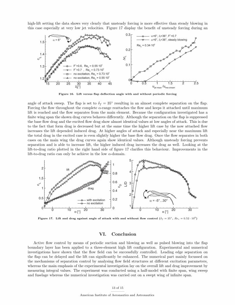
The effect is also identifiable through the behaviour of the blade exit angle behind the trailing edge of themain airfoil (12(c) and 12(d)). Through optimal flow excitation at the flap the blade exit angle of the mainairfoil could be extend from 3◦ (natural flow) to 8◦ compared with the angle of attack (6◦). The reason forthe effectiveness of periodic excitation are the vortices generated by the perturbation. Using the method offeature-based comparison of flow fields developed by the Zuse Institute Berlin (ZIB),24–27 the time-dependentbehaviour of the dominant structures and their size in the unforced and forced flow could be identified. Theextraction of features as well-defined geometric objects is a prerequisite for distance measurements and extentquantifications. Figures 12(a) and 12(b) show the extracted core lines of the dominant vortices, scaling withthe value of the vortex core criterion λ2 and tinted with the contour-color of the pressure distribution. Thenatural flow above the flap is mainly governed by large-scale vortex shedding from the flap trailling edgewhich is nearly eliminated in the optimal excited flow (see figures 12 and 13). Small-sized vortices generatedby periodic suction and blowing above the perturbation slit enable the transport of energy from the mainflow to the recirculation near the wall. Thereby the time-average detachment position moves downstream,the recirculation area is reduced and the downflow condition is modified. Figure 14 shows this effect. Thelarge swirled vortex above the flap trailling edge in the natural flow dissapears with the excitation, moreupstream two small swirled vortices are generated and the strong cross flow near the flap surface is clearlynarrowed. The character of the optimum perturbed structures is deeply three-dimensional (see figures 13(b)and 12(c)) whereby the distribution of perturbation energy is improved and the generation of large coherentvortices is suppressed.
All investigations by means of pulsed blowing are carried out by two-dimensional simulations. The studieswith variable excitation frequencies and intensities show that active flow control by pulsed blowing could notachieve the gain in lift seen for excitation by periodic suction and blowing. The change in lift is dependent onthe duty cycle used (see figure 15(b)). The duty cycle is defined as the blowing duration applied to the cycle
10 of 15
American Institute of Aeronautics and Astronautics
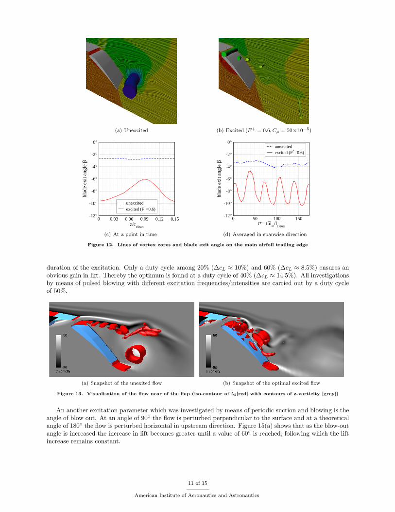
(a) Unexcited (b) Excited (F+ = 0.6, Cµ = 50×10−5)
0 0.03 0.06 0.09 0.12 0.15z/c
clean
-12°
-10°
-8°
-6°
-4°
-2°
0°
blad
e ex
it an
gle β
unexcitedexcited (F
+=0.6)
(c) At a point in time
0 50 100 150t*= t⋅u∞/l
clean
-12°
-10°
-8°
-6°
-4°
-2°
0°
blad
e ex
it an
gle β
unexcitedexcited (F
+=0.6)
(d) Averaged in spanwise direction
Figure 12. Lines of vortex cores and blade exit angle on the main airfoil trailing edge
duration of the excitation. Only a duty cycle among 20% (∆cL ≈ 10%) and 60% (∆cL ≈ 8.5%) ensures anobvious gain in lift. Thereby the optimum is found at a duty cycle of 40% (∆cL ≈ 14.5%). All investigationsby means of pulsed blowing with different excitation frequencies/intensities are carried out by a duty cycleof 50%.
(a) Snapshot of the unexited flow (b) Snapshot of the optimal excited flow
Figure 13. Visualisation of the flow near of the flap (iso-contour of λ2[red] with contours of z-vorticity [grey])
An another excitation parameter which was investigated by means of periodic suction and blowing is theangle of blow out. At an angle of 90◦ the flow is perturbed perpendicular to the surface and at a theoreticalangle of 180◦ the flow is perturbed horizontal in upstream direction. Figure 15(a) shows that as the blow-outangle is increased the increase in lift becomes greater until a value of 60◦ is reached, following which the liftincrease remains constant.
11 of 15
American Institute of Aeronautics and Astronautics

(a) Unexcited flow (b) Excited flow (F+ = 0.6, Cµ = 50 × 10−5)
Figure 14. Illuminated streamlines showing the 3d character of the flow above the flap of the infinite wing
0 20 40 60 80 100 120 140 160 180
angle of blow out βa
0%
2%
4%
6%
8%
10%
12%
14%
16%
chan
ge in
mea
n lif
t coe
ffic
ient
∆c L
(2D) F+= 0.6 Cµ= 114⋅10
-5
(a) Increase in the mean lift coefficient versus theangle of exit
0% 20% 40% 60% 80% 100%
duty cycle τ
0%
2%
4%
6%
8%
10%
12%
14%
16%
chan
ge in
mea
n lif
t coe
ffic
ient
∆c L
(2D) F+= 0.6 Cµ= 114 ⋅10
-5
(b) Increase in the mean lift coefficient versus theduty cycle of pulsed blowing
Figure 15. Effect another excitation parameters at the 2D flow field
V.B. Experiments
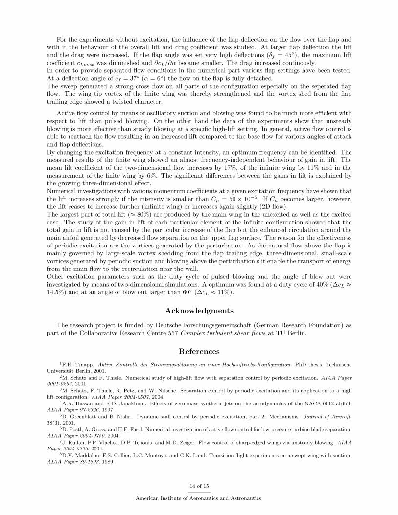
The experimental results have been conducted at various Reynolds numbers reaching from very low (Rec =0.3 · 106, u∞ = 10m/s) to a maximum of about Rec = 0.85 · 106 (u∞ = 29m/s). Most of the resultspresented in this manuscript were gathered at a Reynolds number of around 0.7 · 106 (u∞ = 25m/s) whichis close to the Reynolds number used in the numerical investigation. Besides investigations of excitationfrequency, amplitude, duty cycle and various different excitation modes covered in the numerical part, themain interest in the experiment is the influence of periodic forcing on the aerodynamic forces (primarily liftand drag) for different high-lift settings and Reynolds numbers. Figure 16 displays exemplary lift curveswith and without forcing. The angle of attack is fixed at α = 6◦ while only the flap deflection is increasedin one degree steps from δf = 14◦ to δf = 45◦. The base flow lift curve (line with square symbols, left handside diagram) shows a constant or slightly decreasing lift once the flap deflection is higher than δf = 30◦.At higher angles above δf = 40◦ the lift drops clearly indicating a separated flow on the flap. Once activeflow control is turned on, separation is prevented shifting the curve to the left and to higher lift values. Theincrease in lift even at very low flap deflection is due to the separated flow behind the flap tracks (coveredby fairings) that is suppressed by active flow control. But even at higher deflection angle where the flowstarts to separate from the complete flap, unsteady forcing is able to keep the flow attached resulting in anincreased lift compared to the base flow without forcing. There are a lot of parameters influencing the resultthat depend on the initial condition of slot location and wall jet direction. As compressed air and valves areused to exite the flow, unsteady excitation is easily compared to steady blowing by opening the valves. Theright hand side diagram shows a selected result taken at a low Reynolds number of Rec = 0.34 · 106 becauseat higher Reynolds numbers the ratio of mean jet velocity and free stream velocity decreases. One reason isthe necessary tube length between valve and slot location that causes severe pressure losses. For a specific
12 of 15
American Institute of Aeronautics and Astronautics
high-lift setting the data shows very clearly that unsteady forcing is more effective than steady blowing inthis case especially at very low jet velocities. Figure 17 display the benefit of unsteady forcing during an
Figure 16. Lift versus flap deflection angle with and without periodic forcing
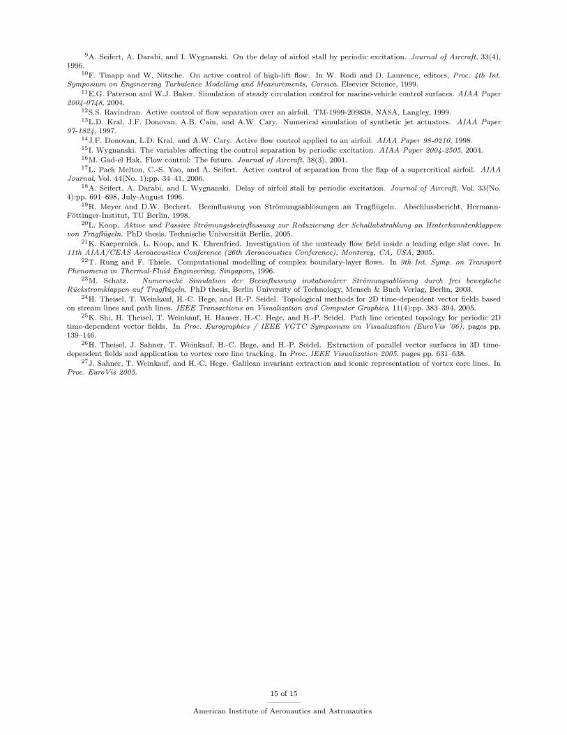
angle of attack sweep. The flap is set to δf = 35◦ resulting in an almost complete separation on the flap.Forcing the flow throughout the complete α-range reattaches the flow and keeps it attached until maximumlift is reached and the flow separates from the main element. Because the configuration investigated has afinite wing span the shown drag curves behaves differently. Although the separation on the flap is suppressedthe base flow drag and the excited flow drag show almost identical values at low angles of attack. This is dueto the fact that form drag is decreased but at the same time the higher lift case by the now attached flowincreases the lift depended induced drag. At higher angles of attack and especially near the maximum liftthe total drag in the excited case is even slightly higher the base flow drag. Once the flow separates in bothcases on the main wing the drag curves again show identical values. Although unsteady forcing preventsseparation and is able to increase lift, the higher induced drag increases the drag as well. Looking at thelift-to-drag ratio plotted in the right hand side of figure 17 clarifies this behaviour. Improvements in thelift-to-drag ratio can only be achieve in the low α-domain.
Figure 17. Lift and drag against angle of attack with and without flow control (δf = 35◦, Rec = 0.52 · 106)
VI. Conclusion
Active flow control by means of periodic suction and blowing as well as pulsed blowing into the flapboundary layer has been applied to a three-element high lift configuration. Experimental and numericalinvestigations have shown that the flow field can be successfully controlled. Leading edge separation onthe flap can be delayed and the lift can significantly be enhanced. The numerical part mainly focussed onthe mechanisms of separation control by analysing flow field structures at different excitation parameters,whereas the main emphasis of the experimental investigation lay on the overall lift and drag improvement bymeasuring integral values. The experiment was conducted using a half-model with finite span, wing sweepand fuselage whereas the numerical investigation was carried out on a swept wing of infinite span.
13 of 15
American Institute of Aeronautics and Astronautics
For the experiments without excitation, the influence of the flap deflection on the flow over the flap andwith it the behaviour of the overall lift and drag coefficient was studied. At larger flap deflection the liftand the drag were increased. If the flap angle was set very high deflections (δf = 45◦), the maximum liftcoefficient cLmax was diminished and ∂cL/∂α became smaller. The drag increased continously.In order to provide separated flow conditions in the numerical part various flap settings have been tested.At a deflection angle of δf = 37◦ (α = 6◦) the flow on the flap is fully detached.The sweep generated a strong cross flow on all parts of the configuration especially on the seperated flapflow. The wing tip vortex of the finite wing was thereby strengthened and the vortex shed from the flaptrailing edge showed a twisted character.
Active flow control by means of oscillatory suction and blowing was found to be much more efficient withrespect to lift than pulsed blowing. On the other hand the data of the experiments show that unsteadyblowing is more effective than steady blowing at a specific high-lift setting. In general, active flow control isable to reattach the flow resulting in an inereased lift compared to the base flow for various angles of attackand flap deflections.By changing the excitation frequency at a constant intensity, an optimum frequency can be identified. Themeasured results of the finite wing showed an almost frequency-independent behaviour of gain in lift. Themean lift coefficient of the two-dimensional flow increases by 17%, of the infinite wing by 11% and in themeasurement of the finite wing by 6%. The significant differences between the gains in lift is explained bythe growing three-dimensional effect.Numerical investigations with various momentum coefficients at a given excitation frequency have shown thatthe lift increases strongly if the intensity is smaller than Cµ = 50 × 10−5. If Cµ becomes larger, however,the lift ceases to increase further (infinite wing) or increases again slightly (2D flow).The largest part of total lift (≈ 80%) are produced by the main wing in the unexcited as well as the excitedcase. The study of the gain in lift of each particular element of the infinite configuration showed that thetotal gain in lift is not caused by the particular increase of the flap but the enhanced circulation around themain airfoil generated by decreased flow separation on the upper flap surface. The reason for the effectivenessof periodic excitation are the vortices generated by the perturbation. As the natural flow above the flap ismainly governed by large-scale vortex shedding from the flap trailing edge, three-dimensional, small-scalevortices generated by periodic suction and blowing above the perturbation slit enable the transport of energyfrom the main flow to the recirculation near the wall.Other excitation parameters such as the duty cycle of pulsed blowing and the angle of blow out wereinvestigated by means of two-dimensional simulations. A optimum was found at a duty cycle of 40% (∆cL ≈14.5%) and at an angle of blow out larger than 60◦ (∆cL ≈ 11%).
Acknowledgments
The research project is funded by Deutsche Forschungsgemeinschaft (German Research Foundation) aspart of the Collaborative Research Centre 557 Complex turbulent shear flows at TU Berlin.
References
1F.H. Tinapp. Aktive Kontrolle der Stromungsablosung an einer Hochauftriebs-Konfiguration. PhD thesis, TechnischeUniversitat Berlin, 2001.
2M. Schatz and F. Thiele. Numerical study of high-lift flow with separation control by periodic excitation. AIAA Paper2001-0296, 2001.
3M. Schatz, F. Thiele, R. Petz, and W. Nitsche. Separation control by periodic excitation and its application to a highlift configuration. AIAA Paper 2004-2507, 2004.
4A.A. Hassan and R.D. Janakiram. Effects of zero-mass synthetic jets on the aerodynamics of the NACA-0012 airfoil.AIAA Paper 97-2326, 1997.
5D. Greenblatt and B. Nishri. Dynamic stall control by periodic excitation, part 2: Mechanisms. Journal of Aircraft,38(3), 2001.
6D. Postl, A. Gross, and H.F. Fasel. Numerical investigation of active flow control for low-pressure turbine blade separation.AIAA Paper 2004-0750, 2004.
7J. Rullan, P.P. Vlachos, D.P. Telionis, and M.D. Zeiger. Flow control of sharp-edged wings via unsteady blowing. AIAAPaper 2004-0226, 2004.
8D.V. Maddalon, F.S. Collier, L.C. Montoya, and C.K. Land. Transition flight experiments on a swept wing with suction.AIAA Paper 89-1893, 1989.
14 of 15
American Institute of Aeronautics and Astronautics
9A. Seifert, A. Darabi, and I. Wygnanski. On the delay of airfoil stall by periodic excitation. Journal of Aircraft, 33(4),1996.
10F. Tinapp and W. Nitsche. On active control of high-lift flow. In W. Rodi and D. Laurence, editors, Proc. 4th Int.Symposium on Engineering Turbulence Modelling and Measurements, Corsica. Elsevier Science, 1999.
11E.G. Paterson and W.J. Baker. Simulation of steady circulation control for marine-vehicle control surfaces. AIAA Paper2004-0748, 2004.
12S.S. Ravindran. Active control of flow separation over an airfoil. TM-1999-209838, NASA, Langley, 1999.13L.D. Kral, J.F. Donovan, A.B. Cain, and A.W. Cary. Numerical simulation of synthetic jet actuators. AIAA Paper
97-1824, 1997.14J.F. Donovan, L.D. Kral, and A.W. Cary. Active flow control applied to an airfoil. AIAA Paper 98-0210, 1998.15I. Wygnanski. The variables affecting the control separation by periodic excitation. AIAA Paper 2004-2505, 2004.16M. Gad-el Hak. Flow control: The future. Journal of Aircraft, 38(3), 2001.17L. Pack Melton, C.-S. Yao, and A. Seifert. Active control of separation from the flap of a supercritical airfoil. AIAA
Journal, Vol. 44(No. 1):pp. 34–41, 2006.18A. Seifert, A. Darabi, and I. Wygnanski. Delay of airfoil stall by periodic excitation. Journal of Aircraft, Vol. 33(No.
4):pp. 691–698, July-August 1996.19R. Meyer and D.W. Bechert. Beeinflussung von Stromungsablosungen an Tragflugeln. Abschlussbericht, Hermann-
Fottinger-Institut, TU Berlin, 1998.20L. Koop. Aktive und Passive Stromungsbeeinflussung zur Reduzierung der Schallabstrahlung an Hinterkanntenklappen
von Tragflugeln. PhD thesis, Technische Universitat Berlin, 2005.21K. Kaepernick, L. Koop, and K. Ehrenfried. Investigation of the unsteady flow field inside a leading edge slat cove. In
11th AIAA/CEAS Aeroacoustics Conference (26th Aeroacoustics Conference), Monterey, CA, USA, 2005.22T. Rung and F. Thiele. Computational modelling of complex boundary-layer flows. In 9th Int. Symp. on Transport
Phenomena in Thermal-Fluid Engineering, Singapore, 1996.23M. Schatz. Numerische Simulation der Beeinflussung instationarer Stromungsablosung durch frei bewegliche
Ruckstromklappen auf Tragflugeln. PhD thesis, Berlin University of Technology, Mensch & Buch Verlag, Berlin, 2003.24H. Theisel, T. Weinkauf, H.-C. Hege, and H.-P. Seidel. Topological methods for 2D time-dependent vector fields based
on stream lines and path lines. IEEE Transactions on Visualization and Computer Graphics, 11(4):pp. 383–394, 2005.25K. Shi, H. Theisel, T. Weinkauf, H. Hauser, H.-C. Hege, and H.-P. Seidel. Path line oriented topology for periodic 2D
time-dependent vector fields. In Proc. Eurographics / IEEE VGTC Symposium on Visualization (EuroVis ’06), pages pp.139–146.
26H. Theisel, J. Sahner, T. Weinkauf, H.-C. Hege, and H.-P. Seidel. Extraction of parallel vector surfaces in 3D time-dependent fields and application to vortex core line tracking. In Proc. IEEE Visualization 2005, pages pp. 631–638.
27J. Sahner, T. Weinkauf, and H.-C. Hege. Galilean invariant extraction and iconic representation of vortex core lines. InProc. EuroVis 2005.
15 of 15
American Institute of Aeronautics and Astronautics