Embed Size (px)
Citation preview
Indian Journal of Textile Research
Vol. 9. De<;ember 1984, pp. 123-129
Control of Jute Yarn Tension during Preparatory Processes
P K BHATTACHARYYA & B L BANERJEE
Indian Jute Industries' Research Association, Calcutta 700088
Receil'ed 2 March 1984; accepted 3 May 1984
//1.he nature and magnitude of tension variation during preparatory processes for jute yarn has been studied under actual
production conditions with a view to minimizing the tension variation within a weaver's beam. It is found that the tension
varies wiih the different diameters and locations of the spools during warping. Proper adjustments of the tensioning device atthe creel during warping and of braking force on the warper's beam during sizing minimize tension variation. and as a result
there are fewer warp breaks and an improvement of yarn and fabric properti~
To achieve the desired weaving performance andfabric quality, it is of utmost importance to have agood-quality weaver's beam. Among the factors which
determine the quality of a beam, uniformity in yarntension is perhaps the most important one. Hence, thewarp sheet should be wound at a uniform tensionthroughout the building of weaver's beam, and the
variation in tension among individual yarns should beas minimum as possible. During warping, i.e. prebeaming process, the yarn tension varies because of the
varying diameters and locations of spools at the creel,unequal angle of yarn deflection at the guide bars anddividing reeds, design and loading system of yarntensioners, etc.1 -5. During slashing, i.e. beamingprocess, the uniformity in yarn tension depends mainlyon the braking moment applied on the head of thewarper's beam, which has to be altered with the
diminution in the yarn content of war per's beam6 -12.Although detailed studies on yarn tensiOn variation
. during preparatory processes have been made withcotton and other yarns 1-12, no systematic andquantitative study has been made so far with jute yarn,the processing technology of which is fairly old andinvolves subjective adjustments of machines forcontrolling the yarn tension.
The factors influencing the unwinding tension ofjute yarns from spinning bobbin and spool have beeninvestigated earlier by Bhattacharyya et al.13 on aprototype machine developed for the purpose. Therelationships between yarn tension during unwindingand each of the variables like yarn speed, grist, balloonheight, package position and dimension, and disctensioner have been established.
The aim of the present study was to estimate thenature and magnitude of tension variation duringpreparatory processes under the existing systemsfollowed by jute mills and to determine its effect on the
warp breakage rate, and yarn and fabric properties.Attempts have also been made to minimize the tensionvariation in each stage of the preparatory processes
and hence improve the warp beam quality, warpbreakage rate, and yarn and fabric properties.
Experimental ProcedureTo control the yarn tension variation, it is essential
to know the causes of such variation. Since during prebeaming with jute yarn, the tension variations due to
different locations and sizes of the packages on thecreel were not known, we felt it necessary to study theseaspects before starting the main experimental work.
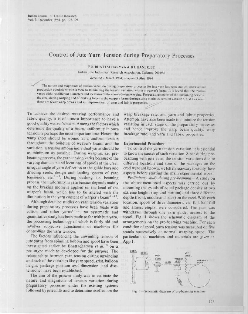
Preliminary study during pre-beaming-A study onthe above-mentioned aspects wl!-s carried out bymounting the spools of equal package density at twoextreme heights (top and bottom) and three differentdepths (front, middle and back) on the creeL With eachlocation, spools of three diameters, viz. full, half-fulland almost empty, were considered. The yarn waswithdrawn through one yarn guide, nearest to thespooL Fig. I shows the schematic diagram of thearrangements on the pre-beaming machine. For eachcondition of spool, yarn tension was measured on fivespools successively at normal warping speed. Theparticulars of machines and materials are given inApp.l.
Fig. I-Schematic diagram of pre-beaming machine
123
INDIAN 1. TEXT. RES .. VOL. 9. DECEMBER 1984
s
w
The i"esults of the experiment (Table 1) show that the
yarn tension increases both with the depletion of thespool and with increase in distance of the spool fromthe head-stock of the machine, which is in agreementwith the finding of Klaueser!4. The effect of distance
is, however, more significant with the almost emptyspool. The height of the spool on the creel has nosignificant effect on yarn tension. The standarddeviation (a) and CV% of yarn tension also show asimilar trend of variation as for yarn tension.
Study conditions (genera~- The entire study wasconducted in a jute mill under actual manufacturingconditions on the same machines for a given quality offabric. The mechanical conditions of all the machines
were good and kept unaltered throughout the study.The tensions of 50 randomly selected warp ends weremeasured just'after the measuring roller during pre
beamin~ and just before the size bath and the dividingreed during beaming. Care was taken to maintain
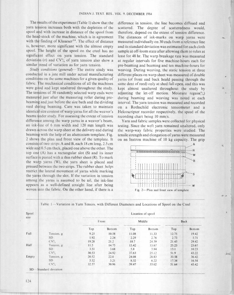
identical size content of warp yarns for all the weaver'sbeams under study. For assessing the extent of tensiondifference among the warp yarns in a weaver's beam,an ink-line of 6 mm width and 120 mm length wasdrawn across the warp sheet at the delivery end during
beaming with the help of an aluminium template. Fig.2 shows the plan and front view of the template. Itconsist~ of two strips A and B, each 18 cm long, 2.5 cmwide and 0.5 cm thick, placed one above the other. Thetop one (A) has a rectangular slot (S) and its innersurface is pasted with a thin rubber sheet (R). To markthe warp yarns (W), the yarn sheet is placed andpressed between the two strips. The rubber sheet helpsrestrict the lateral movement of yarns while markingthe yarns through the slot. If the variation in tensionamong the yarns is assumed to be nil, the ink-lineappears as a well-defined straight line after beingwoven into the fabric. On the other hand, if there is a
difference in tension, the line becomes diffused and
scattered. The degree of scatteredness would,therefore, depend on the extent of tension difference.
The distances of ink-marks on warp yarns weremeasured individually on 30 ends from a reference lineand its standard deviation was estimated for each cloth
sample at off-loom state after allowing them to relax at
least for 48 hr. The warp breakage rate was measuredat regular intervals for five machine-hours each forpre-beaming and beaming and ten machine-hours forweaving. During weaving, the static tension at three
different places on warp sheet was measured of doubleyarns (of front and back heald passing through thesame dent of reed) only at shed full open, and this waskept almost unaltered throughout the study byadjusting the let-off motion. Moisture regain(%)during beaming and weaving was noted at eachinterval. The yarn tension was measured and recordedon a Rothschild electronic tensiometer and a
Helcoscripter recorder respectively, the speed of therecording chart being 10 mm/s ..
Yarn and fabric samples were collected for physicaltesting. Since the weft yarn remained unaltered, onlythe warp-way fabric properties were studied. Thetensile strength and elongation of yarns were measuredon an Instron machine of 10 kg capacity. The grip
A
f"";,"!'i6'm<lWIffW({({"!'i(f~(f""~~I : I •
I I : I B
rllWWlJ 11111/1111 i :I I It 1 , I I II I I I I I I I I
~rnrrrnr I , I I ' I I II J t I r I ,'1 I
IIIII1II
Fig. 2- Plan and front view of template
Table I~Variation in Yarn TensiOi. with Different Diameters and Locations of Spool on the Creel
Full
Half
Empty
Spoolsize
Tension, gSOCY/oTension, gSO
CY%
Tension, gSOCY%
SO-Standard deviation
Location of spool--Fron!MiddleBack
---TopBottomTopBottomTopBottom
9.25
10.5811.0811.3312.7519.42
1.92
2.242.292.762.735.7119.28
21.218.724.3921.4529.4211.5
14.7515.4215.6725.2523.673.51
3.685.83.9413.110.2330.53
24.9237.6325.1251.943.2220.52
22.024.0828.8333.5836.425.52
3.218.326.2217.3416.5432.57
30.9639.4733.0251.6445.42
124
BHATTACHARYYA & BANERJEE: CONTROL OF JUTE YARN TENSION
Fig. 3-Modified braking system
KNUCKLE JOINT
BEAM HEAD
Required springbalance readingfor keeping yarntension constant
at 105.82
kg
30
20
10
STEEL STRAP
LEATHER STRAP
SPRING BALANCE
105.82
142.58234.07
Tension
of singleyarn
g
540
321.64
219.12
Weight ofbeam with
yarnkg
50.15
32.00
18.00
Radius of
warper's beamwith yarn
cm
Results and· Discussion
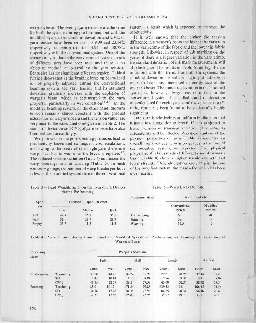
The details of machines and fabric are given in App.1. The calculated values of yarn tension at differentdecreasing radii of warper's beam and the brakingforces required to obtain the minimum and uniformtensions throughout are given in Table 2. Table 3shows the different dead weights on the disc-typetensioning devices of the pre-beaming machine forcontrolling the variation in yarn tension. The deadweights were selected by trial and error, keeping inview the operational simplicity and the experimentalresults as reported under 'Preliminary study duringpre-beaming'. Table 4 shows the yarn tension duringboth the conventional and modified systems of prebeaming and beaming at three decreasing sizes of
Table 2- Theoretical Values of Yarn Tension and SpringBalance Readings for Different Braking Moments
length, breaking period, cross-head speed and chartspeed were kept at 61 em, 20 ±5 s, 5 cm/min and 10cm/min respectively. In all, 150 yarn samples weretested. The tensile strength and elongation of fabricswere measured on an Instron machine of 100 kgcapacity. The fabric strip dimension and breakingperiod were kept at 20 x 5 cm and 10± 5 s respectivelyand both cross-head and chart speeds at 30 cm/min.The warp crimp of fabrics was measured on a Shirleycrimp tester of 80 g load. In all, 20 fabric samples weretested.
Study conditions (special)- The study was carriedout under the existing as well as modified conditions.
Under existing condition: At each stage of prebeaming, beaming and weaving, the yarn tension wasmeasured and the end breakage rate of warp yarn wasnoted with the normal processing system followed bythe jute mills. This system has been referred to asconventional system in the discussion section.
Under modified condition: To minimize the tensionvariation, full spools were taken on the creel formaking warper's beams and the dead weights of thetensioning devices at the creel were adjusted on thebasis of the experimental results reported under'Preliminary study during pre-beaming' to suit thelocation and diameter of the spool. Yarn tension andend breakage rate were then noted during theoperation of the machine.
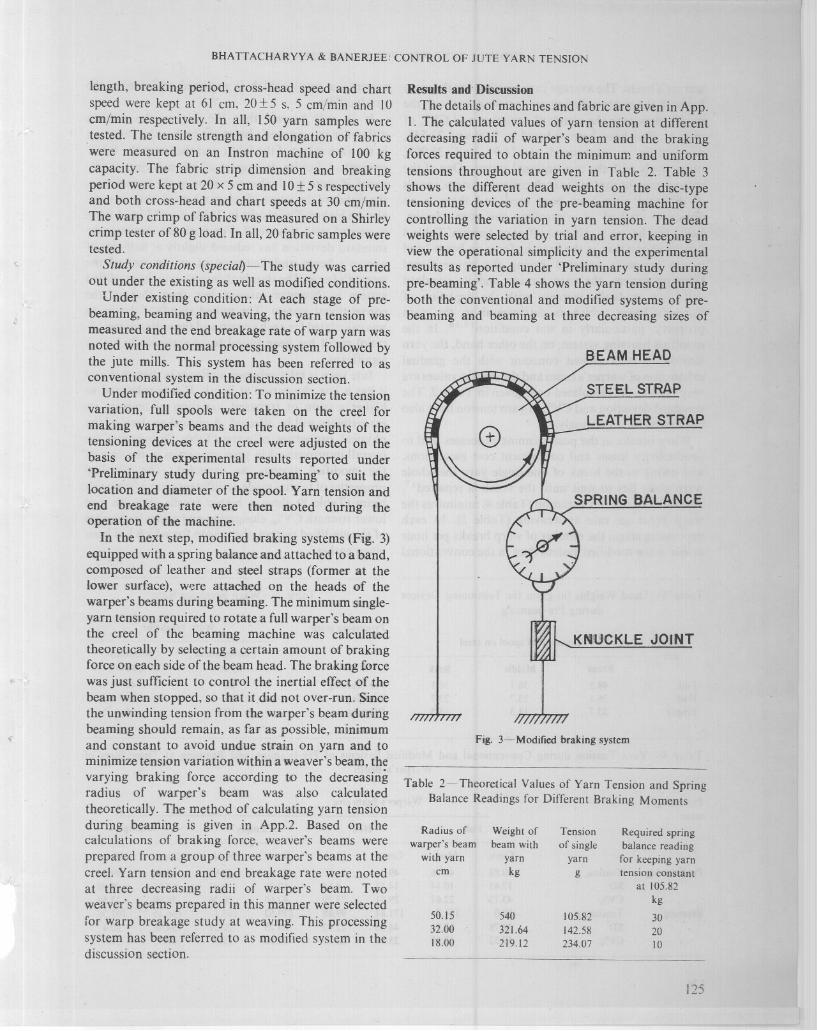
In the next step, modified braking systems (Fig. 3)equipped with a spring balance and attached to a band,composed of leather and steel straps (former at thelower surface), were attached on the heads of thewarper's beams during beaming. The minimum singleyarn tension required to rotate a full warper's beam onthe creel of the beaming machine was calculatedtheoretically by selecting a certain amount of brakingforce on each side of the beam head. The braking forcewas just sufficient to control the inertial effect of thebeam when stopped, so that it.did not over-run. 'Sincethe unwinding tension from the warper's beam duringbeaming should remain, as far as possible, minimumand constant to avoid undue strain on yarn and tominimize tension variation within a weaver's beam, thevarying braking force according to the decreasingradius of warper's beam was also calculatedtheoretically. The method of calculating yarn tensionduring beaming is given in App.2. Based on thecalculations of braking force, weaver's beams wereprepared from a group of three warper's beams at thecreel. Yarn tension and end breakage rate were notedat three decreasing radii of warper's beam. Twoweaver's beams prepared in this manner were selectedfor warp breakage study at weaving. This processingsystem has been referred to as modified system in thediscussion section.
125
INDIAN J. TEXT. RES .. VOL. 9, DECEMBER 1984
warper's beam. The average yarn tensions are the samefor botlh the systems during pre-beaming, but with themodifi~d system, the standard deviation and CV% ofyarn tension have been reduced to 9.09 and 23.54%.
respectively as compared to 14.91 and 38.98%respectively with the conventional system. One of thereasons may be that in the conventional system, spoolsof diffJerent sizes have been used and there is noobjective method of controlling the yarn tension.Beam size has no significant effect on tension. Table 4
furthe~ shows that as the braking force on beam-headis not properly adjusted during the conventionalbeaming system, the yarn tension and its standarddeviatibn gradually increase with the depletion ofwarpeJ;'s beam, which is detrimental to the yarnproper,ty, particularly in wet condition1s,16. In themodified beaming system, on the other hand, the yarntension remains almost constant with the gradualexhaustion of warper's beam and the tension values arevery near to the calculated ones given in Table 2. The
standard deviation and CV% of yarn tension have also'been reduced accordingly.
Warp breaks in the post-spinning processes lead toproduetivity losses and consequent cost escalations,and owing to the break of one single yarn the wholewarp sheet has to wait until the break is repaired 17.
The reduced tension variation (Table 4) minimizes thewarp breakage rate at weaving (Table 5). In ea.chprocessing stage, the number of warp breaks per houris less in the modified system than in the conventional
Table 3-Dead Weights(in g) on the Tensioning Devicesduring Pre-beaming
system-a result which is expected to increase theproductivity.
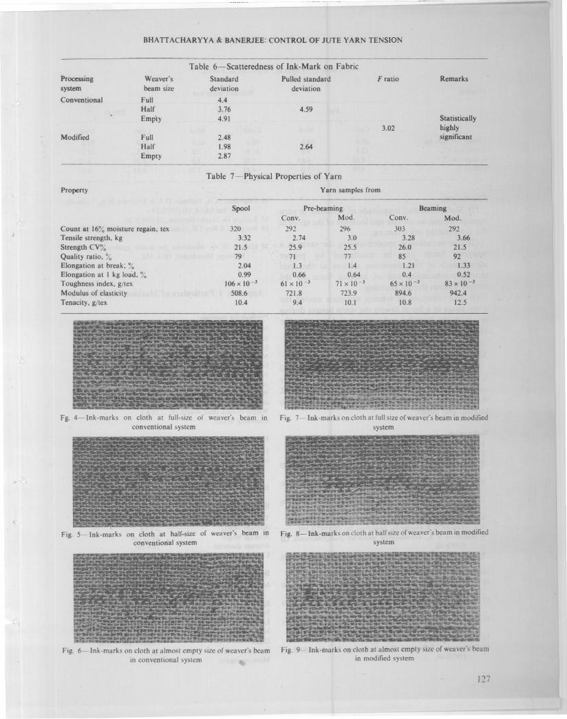
It is well known that the higher the tensiondifference in a weaver's beam the higher the variationin the yarn crimp of the fabric and the lower the'fabricstrength. Likewise, in respect of ink marking on theyarns, if there is a higher variation in the yarn crimp,the standard deviation of ink mark measurements will
also be higher. The results in Table 6 and Figs 4-9 arein accord with this trend. For both the systems, thestandard deviation has reduced slightly at half-size ofweaver's beam and increased at empty size of theweaver's beam. The standard deviation in the modifiedsystem is, however, always less than that in theconventional system. The pulled standard deviationwas calculated for each system and the variance test (Fratio) result has been found to be statistically highlysignificant.
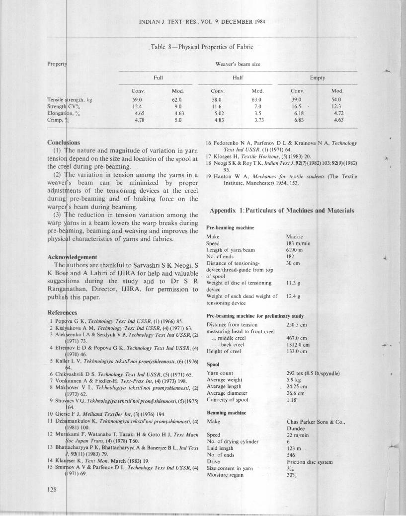
Jute yarn is relatively non-uniform in diameter andit has a low elongation at break. If it is subjected tohigher tension or transient variation of tension, itsextensibility will be affected. A critical analysis of thephysical properties of yarn (Table 7) indicates anoverall improvement in yarn properties in the case ofthe modified system, as expected. The physicalproperties offabrics made at different sizes of weaver'sbeam (Table 8) show a higher tensile strength andlower strength CV%, elongation and crimp in the caseof the modified system, the reason for which has beengiven earlier.
Table 5--Warp Breakage Rate
Processing stage Warp breaks/hr
Spool Location of spool on creelsize Front
MiddleBack
Full
48.536.136.1
Half
36.123.723.7
Empty
23.711.311.3
Pre-beaming
Beaming
Weaving
Conventional
system
6126
10.5
Modified
system
4814
5
Table 4- Yarn Tension during Conventional and Modified Systemsof Pre-beamingand Beaming at Three Sizes ofWarper's Beam
Processing
stage
Pre-beaming
Beaming
126
Tension, gSD
CV%Tension, gSDCV%
Warper"s beam size
Full
HalfEmptyAverage_._--
--------Conv.
Mod.Conv.Mod.Conv.Mod.Conv.Mod.
39.88
44.7649.2431.9229.240.9239.4439.217.45
10.1414.538.8112.768.3314.919.09
43.75
22.6729.5L27.5943.6920.3638.9823.54
88.0
101.7171.8499.88239.52103.1166.45101.5634.78
17.9644.3522.9284.2520.3154.4620.4
39.52
17.6625.8122.9535.1719.733.520.1
I'=I"~""'I
BHATTACHARYYA & BANERJEE: CONTROL OF JUTE YARN TENSION
Processingsystem
Conventional
Modified
Property
Table 6-Scatteredness of Ink-Mark on Fabric
Weaver's
StandardPulled standardF ratioRemarksbeam size
deviationdeviation
Full
4.4Half
3.764.59
Empty
4.91 Statistically3.02
highlyFull
2.48 significantHalf
1.982.64
Empty
2.87
Table 7-Physical Properties of Yarn
Yarn samples from
SpoolPre-beaming BeamingConv.
Mod.Conv.Mod.
Count at 16% moisture regain, tex
320292296303292Tensile strength, kg
3.322.743.03.283.66
Strength CV%21.525.925.526.021.5
Quality ratio, %7971778592
Elongation at break; %2.041.31.41.211.33
Elongation at I kg loa'd, %0.990.660.640.40.52
Toughness index, g/tex
106x 10-361 x 10-371 x 10-365 x 10-383 x 10-3
Modulus of elasticity
508.6721.8723.9894.6942.4
Tenacity, g/tex
10.49.410.110.812.5
Fg. 4-lnk-marks on cloth at full-size of weaver's beam inconventional system
Fig. 5-lnk-marks on cloth at half-size of weaver"s beam inconventional system
Fig. 6-lnk-marks on cloth at almost empty size of weaver's beamin conventional system
Fig. 7-lnk-marks on cloth at full size of weaver's beam in modifiedsystem
Fig. 8- Ink-marks on cloth at half sizeof weaver's beam in modifiedsystem
Fig. 9-lnk-marks on cloth at almost empty size of weaver's beamin modified system
127
INDIAN 1. TEXT. RES., VOL. 9, DECEMBER 1984
Table 8-Physical Properties of Fabric
Property Weaver's beam size
Full Half Empty
Tensile strength, kg
Strengt~ CV%Elongation, %
Crimp, %
Cony.
59.0
12.4
4.65
4.78
Mod.
62.0
9.04.63
5.0
Cony.
58.0
11.6
5.02
4.83
Mod.
63.0
7.0
3.5
3.73
Cony.
39.0
16.5
6.18
6.83
Mod.
54.0
12.3
4.72
4.63
Appendix 1: Particulars of Machines and Materials
16 Fedorenko N A, Parfenov D L & Krainova N A, TechnologyTextlnd USSR, (I) (1971) 64.
17 Klosges H, Textile Horizons, (5) (1983) 20.18 Neogi S K & Roy T K,Indian Text J, 92(7)(l982) 103; 92(9) (I 982)
95.
19 Hanlon W A, Mechanics for textile students (The TextileInstitute, Manchester) 1954, 153.
Conclusions
(1) The nature and magnitude of variation in yarn!tension depend on the size and location of the spool atthe creel during pre-beaming.
(2) The variation in tension among the yarns in aweaveIi's beam can be minimized by properadjustments of the tensioning devices at the creelduringi pre-beaming and of braking force on thewarpe~'s beam during beaming.
(3) The reduction in tension variation among thewarp )larns in a beam lowers the warp breaks duringpre-beaming, beaming and weaving and improves thephysical characteristics of yarns and fabrics.
AcknowledgementThe authors are thankful to Sarvashri S K Neogi, S
K Bose and A Lahiri of IJIRA for help and valuablesuggestions during the study and to Dr S R
Rangahathan, Director, IJIRA, for permission topublish this paper.
Pre-beaming machine
Make
SpeedLength of yarn/beamNo. of ends
Distance of tensioning
device/thread-guide from top
of spoolWeight of disc of tensioningdevice
Weight of each dead weight of
tensioning device
Mackie
183 m/min6190 m
182
30 cm
1\.3 g
12.4 g
Chas Parker Sons & Co.,
Dundee
22 m/min6
123 m
546
Friction disc system3%
30%
292 tex (8.5 Ib/spyndle)5.9 kg24.25 cm
26.6 cm1.18'
467.0 cm1312.0 cm
133.0 cm
Beaming machine
Make
Speed
No. of drying cylinder
Laid lengthNo. of endsDrive
Size content in yarn
Moisture regain
Pre-beaming machine for preliminary study
Distance from tension 250.5 cm
measuring head to front creel... middle creel
..... back creel
Height of creel
Spool
Yarn count
A verage weight
A verage length
A verage diameter
Conocity of spool
References
I Popova G K, Technology Textlnd USSR, (I) (1966) 85.
2 Kislyakova A M, Technology Text Ind USSR, (4) (1971) 63.
3 Alekseenko I A & Serdyuk V P, Technology Textlnd USSR, (2)
~1971) 73.4 Efremov E D & Popova G K, Technology Textlnd USSR, (4)
~1970) 46.5 Kaller L V, Tekhnologiya tekstifnoi promyshlennosti, (6) (1976)
64.
6 Chik'vashvili D S, Technology Textlnd USSR, (5) (1971) 65.7 Von~annen A & Fiedler.H, Text-Prax Int, (4) (1973) 198.
8 Makhover V L, Tekhnologiya tekstifnoi promyshlennosti, (2)
(1973) 62.9 Shuvaev V G, Tekhnologiya tekstifnoi promyshlennosti, (5)(1975)
164.
10 Gierse F 1, Melliand TextBer Int, (3) (1976) 194.
II Dzhamankulov K, Tekhnologiya tekstifnoi promyshlennosti, (4)
/1981) 100.12 Murhami F, Watanabe T, Tazaki H & Goto H J, Text Mach,~oc Japan Trans, (4) (1978) T60.
13 Bhattacharyya P K, Bhattacharyya A & Banerj;:e B L, Ind TextJ, 93(11)(1983) 79.
14 Klau,eser K, Text Mon, March (1983) 19.
15 Smirnov A V & Parfenov D L, Technology Textlnd USSR, (4)
~1971) 69.
128
Loom and fabric
Make of loom
Type of loom
Loom speed
Reed spaceShed dwell
Take-up motionNo. of heald shaftsLet-off mechanism
Static warp tensionWeave
Ends/dm
Picks/dm
Warp countWeft count
Denting pattern
Leasing patternWidth of cloth
Fabric weight/m2
Cloth quality
Moisture regain
BHATTACHARYYA & BANERJEE: CONTROL OF JUTE YARN TENSION
T
Urquhart Lindsay & Co. Ltd.
Plain, overpick shuttle loom
without temples140 rpm133.4 cm
130', about 1/3 of a pick cycle5 Wheels
Two, with cotton cord healds
Negative, with rope and screw
290±'50 g
1/1, Plain46.75
47.6
292.4 lex (8.5 Ib/spyndle)
309.6 tex (9 Ib/spyndle)
2 in a dent for body, 4 in a
dent for selvedgeI up I down114.3 em
238 gHessian
13%
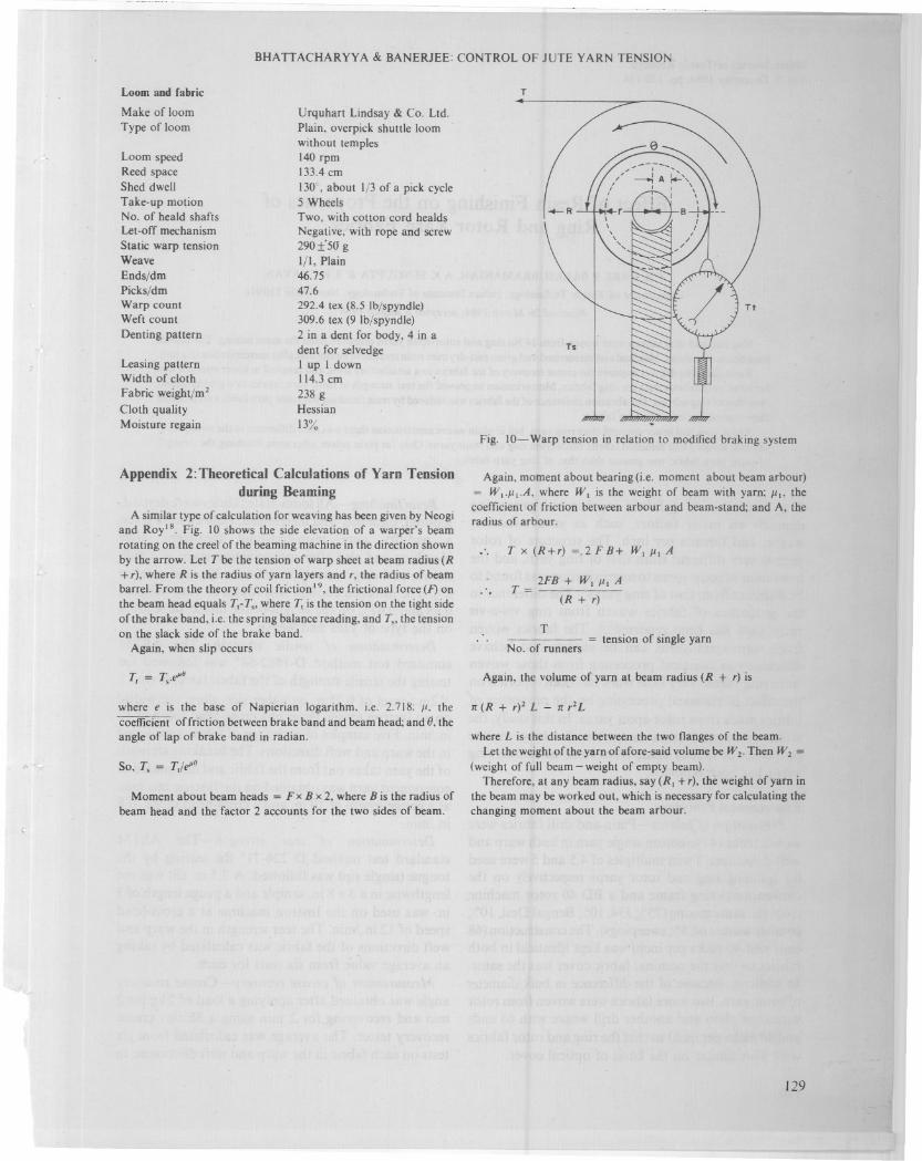
Fig. IO-Warp tension in relation to modified braking system
T x (R+r) =.2 F B+ WI III A
2FB + WI III AT=-----(R + r)
Again, moment about bearing (i.e. moment about beam arbour)
= W1'I'I.A, where WI is the weight of beam with yarn; Ill' thecoefficient of friction between arbour and beam-stand; and A, theradius of arbour.
Appendix 2:Theoretical Calculations of Yarn Tensionduring Beaming
A similar type of calculation for weaving has been given by Neogi
and Royls. Fig. 10 shows the side elevation of a warper's beam
rotating on the creel of the beaming machine in the direction shown
by the arrow. Let T be the tension of warp sheet at beam radius (R+r), where R is the radius of yarn layers and r, the radius of beambarrel. From the theory of coil friction 19, the frictional force (F) onthe beam head equals Tl-T" where Tl is the tension on the tight side
of the brake band, i.e. the spring balance reading, and T" the tensionon the slack side of the brake band.
Again, when slip occurs
T
No. of runnerstension of single yarn
where e is the base of Napicrian logarithm, i.e. 2.718: 1', the'coefficient offriction between brake band and beam head; and 0, the
angle of lap of brake band in radian.
Moment about beam heads = F x B x 2, where B is the radius of
beam head and the factor 2 accounts for the two sides of beam.
Again, the volume of yarn at beam radius (R + r) is
1C (R + r)2 L - 1C r2 L
where L is the distance between the two flanges of the beam.
Let the weight of the yarn of afore-said volume be W2• Then W2 =(weight offull beam - weight of empty beam).
Therefore, at any beam radius, say (RI + r), the weight of yarn inthe beam may be worked out, which is necessary for calculating the
changing moment about the beam arbour.
]29