Embed Size (px)
Citation preview

General rights Copyright and moral rights for the publications made accessible in the public portal are retained by the authors and/or other copyright owners and it is a condition of accessing publications that users recognise and abide by the legal requirements associated with these rights.
Users may download and print one copy of any publication from the public portal for the purpose of private study or research.
You may not further distribute the material or use it for any profit-making activity or commercial gain
You may freely distribute the URL identifying the publication in the public portal If you believe that this document breaches copyright please contact us providing details, and we will remove access to the work immediately and investigate your claim.
Downloaded from orbit.dtu.dk on: Mar 25, 2020
Study on VSC HVDC Modeling and Control Strategies for Wind Power Integration
Korompili, Asimenia; Wu, Qiuwei
Publication date:2013
Document VersionPublisher's PDF, also known as Version of record
Link back to DTU Orbit
Citation (APA):Korompili, A., & Wu, Q. (2013). Study on VSC HVDC Modeling and Control Strategies for Wind PowerIntegration. Technical University of Denmark, Department of Electrical Engineering.

Asimenia Korompili, Qiuwei Wu
Study on VSC-HVDCModelling and Control Strategies
for Wind Power Integration
Research report, October 2013


Asimenia Korompili, Qiuwei Wu
Study on VSC-HVDCModelling and Control Strategies
for Wind Power Integration
Research report, October 2013


Study on VSC-HVDC Modelling and Control Strategies for Wind Power Integration
This report was prepared byAsimenia Korompili, Qiuwei Wu
Release date: October the 20th, 2013Category: 1 (public)Edition: FirstRights: ©Complete or partial reproduction of this publication is autho-
rized provided the source, 2013
Department of Electrical EngineeringCentre for Electric Technology (CET)Technical University of DenmarkElektrovej building 325DK-2800 Kgs. LyngbyDenmark
www.elektro.dtu.dk/cetTel: (+45) 45 25 35 00Fax: (+45) 45 88 61 11E-mail: [email protected]

Preface
This report was carried out during research assistance in a period from 19th ofAugust, 2013 to 20th of October, 2013. The study has been performed at the Centrefor Electric Power and Energy (CEE) at the Electrical Engineering Department ofthe Technical University of Denmark. The work was supervised by Qiuwei Wu.
Asimenia Korompili,
Lyngby,
Sunday, October the 20th, 2013
i/viii


Executive Summary
Recently, more and more offshore wind farms have been integrated to the powersystems. In the next years, these offshore power plants are going to be rated athigher capacities and located in larger distances from the coast. This results ingreater interest in the transmission technologies, which are available for the gridconnection of the offshore wind farms. In this report various transmission systemsare presented. Precisely, the HVAC systems, which have dominated up until nowin the power transfer sector, are briefly analysed, by providing their advantages, aswell as the bottlenecks that occur in their applications. The main focus is givenin the HVDC transmission systems, since they do not exhibit these disadvantages,whereas they additionally present beneficial attributes. This is the reason for whichthe applications of HVDC systems have been increased in the latest years. A briefdescription of different application cases is provided in the introduction of thisreport, while the rest chapters deal with the use of the HVDC technology for thegrid connection of offshore wind farms.
The main structure of the HVDC system is analysed, by describing the role andoperation of its main components. Especially the converter configurations, the de-vices for reactive power compensation, the filter systems and the DC breakers arepresented in details. The presence of different components, with different charac-teristics, leads to alternative system structures. Therefore, a comparison betweenthe different structures is performed, regarding power losses, costs, equipment as-pects and control capabilities. It is concluded that the VSC-HVDC system exhibitsthe most advantageous features for the grid connection of offshore wind farms. Inaddition, various topologies of the HVDC converter stations are analysed.
Furthermore, the control schemes and strategies of the VSC are described in details.The capabilities of the VSC-HVDC technology, provided by its control system, areanalysed. These attributes give the opportunity to the VSC-HVDC transmissionsystem to provide grid support. They imply also benefits for the design of the windturbines, as well as for the operation of the TSOs.
Special focus is given on control strategies for fulfilling requirements concerningLVRT and frequency regulation. The corresponding technical rules, included ingrid codes, are provided and the relevant structures and methods are described.
Finally, more specific requirements are given for the grid connection of offshore windfarms through HVDC systems. These rules derived from the combination of grid
iii/viii

codes for the integration of offshore wind farms and grid codes for the operation ofHVDC transmission systems, connecting power plants to the AC network.
iv/viii

Contents
Contents v
1 Introduction 1
1.1 Background . . . . . . . . . . . . . . . . . . . . . . . . . . . . . . . . 1
1.2 Offshore wind energy . . . . . . . . . . . . . . . . . . . . . . . . . . . 1
1.3 High voltage grid connection of offshore wind farms . . . . . . . . . . 2
1.4 HVAC vs. HVDC transmission technology . . . . . . . . . . . . . . . 4
1.4.1 Dominance of HVAC transmission systems . . . . . . . . . . 4
1.4.2 Disadvantages of HVAC transmission systems . . . . . . . . . 5
1.4.3 Development of HVDC transmission systems . . . . . . . . . 6
1.4.4 Advantages of HVDC transmission systems . . . . . . . . . . 7
1.4.5 Applications of HVDC transmission systems . . . . . . . . . 10
2 HVDC transmission systems 15
2.1 Classic HVDC transmission system . . . . . . . . . . . . . . . . . . . 15
2.1.1 Converter . . . . . . . . . . . . . . . . . . . . . . . . . . . . . 15
2.1.2 Transformers . . . . . . . . . . . . . . . . . . . . . . . . . . . 17
2.1.3 Reactive power supplies . . . . . . . . . . . . . . . . . . . . . 18
2.1.4 Passive harmonic filters . . . . . . . . . . . . . . . . . . . . . 26
2.1.5 Active harmonic filters . . . . . . . . . . . . . . . . . . . . . . 27
2.1.6 Transmission circuit . . . . . . . . . . . . . . . . . . . . . . . 29
2.1.7 Smoothing reactors . . . . . . . . . . . . . . . . . . . . . . . . 30
2.1.8 Surge arresters . . . . . . . . . . . . . . . . . . . . . . . . . . 31
2.2 VSC-HVDC transmission system . . . . . . . . . . . . . . . . . . . . 31
v/viii

2.2.1 Converter . . . . . . . . . . . . . . . . . . . . . . . . . . . . . 31
2.2.2 Transformers . . . . . . . . . . . . . . . . . . . . . . . . . . . 36
2.2.3 Phase reactors . . . . . . . . . . . . . . . . . . . . . . . . . . 36
2.2.4 AC filters . . . . . . . . . . . . . . . . . . . . . . . . . . . . . 36
2.2.5 Transmission circuit . . . . . . . . . . . . . . . . . . . . . . . 36
2.2.6 DC capacitors . . . . . . . . . . . . . . . . . . . . . . . . . . . 37
2.3 VSC-HVDC transmission system for grid connection of offshore windfarms . . . . . . . . . . . . . . . . . . . . . . . . . . . . . . . . . . . 38
2.4 Suitability of transmission systems for grid connection of offshorewind farms . . . . . . . . . . . . . . . . . . . . . . . . . . . . . . . . 38
2.4.1 Power losses . . . . . . . . . . . . . . . . . . . . . . . . . . . . 39
2.4.2 Ratings of cables and converters . . . . . . . . . . . . . . . . 40
2.4.3 Size of the offshore substation . . . . . . . . . . . . . . . . . . 40
2.4.4 Environmental issues . . . . . . . . . . . . . . . . . . . . . . . 41
2.4.5 Feasibility of each transmission system according to windfarm capacity and distance from the shore . . . . . . . . . . . 41
2.5 HVDC system topologies . . . . . . . . . . . . . . . . . . . . . . . . 42
2.5.1 Monopolar HVDC systems . . . . . . . . . . . . . . . . . . . 43
2.5.2 Back-to-back HVDC systems . . . . . . . . . . . . . . . . . . 44
2.5.3 Bipolar HVDC systems . . . . . . . . . . . . . . . . . . . . . 44
2.5.4 Multi-terminal HVDC systems . . . . . . . . . . . . . . . . . 45
2.6 HVDC grids with multi-terminal systems . . . . . . . . . . . . . . . 46
2.6.1 Handling of faults at the DC side of the transmission system 46
2.6.2 VSC-HVDC multi-terminal system topologies . . . . . . . . . 46
2.6.3 Comparison of topologies . . . . . . . . . . . . . . . . . . . . 49
3 Converter control schemes in a VSC-HVDC transmission system 51
3.1 Converter control schemes . . . . . . . . . . . . . . . . . . . . . . . . 51
3.1.1 Inner current controller . . . . . . . . . . . . . . . . . . . . . 53
3.1.2 Outer controllers . . . . . . . . . . . . . . . . . . . . . . . . . 56
3.1.3 Comparison of converter control schemes . . . . . . . . . . . 61
3.2 Capabilities of VSC-HVDC transmission systems . . . . . . . . . . . 62
3.2.1 Controllability . . . . . . . . . . . . . . . . . . . . . . . . . . 62
3.2.2 Active power control and frequency response capability . . . 62
vi/viii

3.2.3 Reactive power control and voltage support capability . . . . 63
3.2.4 Fast response to disturbances . . . . . . . . . . . . . . . . . . 64
3.2.5 Decoupling AC systems . . . . . . . . . . . . . . . . . . . . . 65
3.2.6 Black start capability . . . . . . . . . . . . . . . . . . . . . . 65
3.3 Benefits for wind turbines . . . . . . . . . . . . . . . . . . . . . . . . 66
3.4 Benefits for TSO . . . . . . . . . . . . . . . . . . . . . . . . . . . . . 67
4 LVRT methods at VSC-HVDC grid-connected wind farms 69
4.1 LVRT requirements in E.ON. grid code . . . . . . . . . . . . . . . . 69
4.2 Dealing with faults in the AC grid . . . . . . . . . . . . . . . . . . . 71
4.3 Control structures and methods in VSC-HVDC transmission systemsfor LVRT requirements . . . . . . . . . . . . . . . . . . . . . . . . . . 71
4.3.1 DC chopper . . . . . . . . . . . . . . . . . . . . . . . . . . . . 71
4.3.2 Use of fast data communication . . . . . . . . . . . . . . . . . 73
4.3.3 Frequency control at the wind farm network . . . . . . . . . . 73
4.3.4 Other methods for reducing the active power output of theturbines in the wind farm . . . . . . . . . . . . . . . . . . . . 74
4.3.5 DC voltage control switch-over between converters at the twosides of the transmission system . . . . . . . . . . . . . . . . 74
4.3.6 AC voltage control at the wind farm network . . . . . . . . . 75
4.3.7 Blocking of the converter . . . . . . . . . . . . . . . . . . . . 77
4.4 Dealing with faults in the wind farm network . . . . . . . . . . . . . 77
5 Frequency regulation by VSC-HVDC grid-connected wind farms 79
5.1 Frequency regulation by wind farms . . . . . . . . . . . . . . . . . . 79
5.2 Frequency regulation requirements in the Danish grid code . . . . . 79
5.3 Frequency regulation strategies in VSC-HVDCtransmission systems . . . . . . . . . . . . . . . . . . . . . . . . . . . 80
5.3.1 Use of DC voltage . . . . . . . . . . . . . . . . . . . . . . . . 80
5.3.2 Communication of the onshore grid frequency to the offshoreHVDC converter . . . . . . . . . . . . . . . . . . . . . . . . . 81
5.3.3 Communication of the onshore grid frequency to the turbineconverters . . . . . . . . . . . . . . . . . . . . . . . . . . . . . 81
5.4 Frequency regulation strategies in multi-terminal VSC-HVDC trans-mission systems . . . . . . . . . . . . . . . . . . . . . . . . . . . . . . 81
vii/viii

6 Requirements for the grid connection of wind farms through HVDCsystems 85
6.1 Frequency range . . . . . . . . . . . . . . . . . . . . . . . . . . . . . 85
6.2 Active power controllability . . . . . . . . . . . . . . . . . . . . . . . 87
6.3 Frequency sensitive mode . . . . . . . . . . . . . . . . . . . . . . . . 87
6.3.1 Active power reduction during over-frequency . . . . . . . . . 88
6.3.2 Active power increase during under-frequency . . . . . . . . . 88
6.4 Voltage range . . . . . . . . . . . . . . . . . . . . . . . . . . . . . . . 88
6.5 Reactive power exchange and voltage stability . . . . . . . . . . . . . 89
6.6 Required reactive current during grid faults . . . . . . . . . . . . . . 92
Bibliography 95
Appendix 103
viii/viii

Chapter 1
Introduction
1.1 Background
Nowadays, global climate change is no longer questionable and concerns about itssignificant impact on planet’s life are increasing. For this reason, the EU has putspecific targets to reducing the greenhouse effect and limiting the global warming.Furthermore, exhaustion of fossil fuels, higher energy prices, increasing demand ofpower and energy dependence between countries create huge challenges for gov-ernments all over the world. This situation implies changes in the current energysupply sector, leading to different shares between the various energy resources. Theuse of conventional primary energy types, such as oil and gas, has restricted; onthe other hand, renewable energy resources with zero greenhouse gas emissions, likewind and solar energy, have gained worldwide attention in the recent years [1, 2].
Due to the wide distribution of potential large-scale wind resources all over theworld, wind energy is the most exploited source among the renewable energy types.In 2007 wind was the second energy resource in the EU, with a share of 30 % of theinstalled power capacity. Its global average annual growth rate has reached to be30 % in the last decade. This trend will hardly change in the next years, consideringthe aim of EU to produce 12 − 14 % of electricity from wind by 2020 [2–4].
1.2 Offshore wind energy
A key technology for achieving the aforementioned energy goal of the EU is thelarge offshore wind farms, with capacity of several hundred megawatts. Althoughthe majority of the wind power is nowadays produced by onshore wind turbines,the offshore market is going to be of high interest for the energy policies in the nearfuture [2, 4].
The most important advantage of the offshore location of the wind farms is thehuge wind resources available, giving a high potential for power production. Theseresources are still unexploited; on the contrary, profitable onshore locations in Eu-
1/103

1.3. High voltage grid connection of offshore wind farms
rope have been already used. Moreover, the wind conditions are better in offshoreareas, since the wind speeds are higher and more predictable and the wind fluc-tuations are lower. This implies a higher capacity factor of offshore wind farmscompared to that of the onshore installations. In addition, offshore wind turbinesare less obtrusive than these on land and therefore projects for offshore wind farmsexperience less public resistance [4, 5].
At the moment, wind farms in offshore locations are still more expensive than thoseon land. Two factors characterise mostly their cost: the turbine foundation and thewind farm’s distance from the shore. The foundation cost usually grows up rapidlywith increasing water depth and wave height. The transmission distance stronglyaffects the grid connection costs. In addition, costs of repair and maintenance aresignificantly higher for offshore turbines. For these reasons, up until now, sites closeto the shore, with shallow waters, were preferred for offshore wind farms [4].
However, there is still stimulus for locating the wind farms even further offshore.Often, near-shore sites are subject to various interests, like maritime traffic, coastalfishing, recreational or military activities. In contrast, in offshore areas such re-strictions do not exist. Moreover, visibility, noise disturbance and environmentalconcerns regarding the impact on marine flora and fauna are mitigated [3, 4].
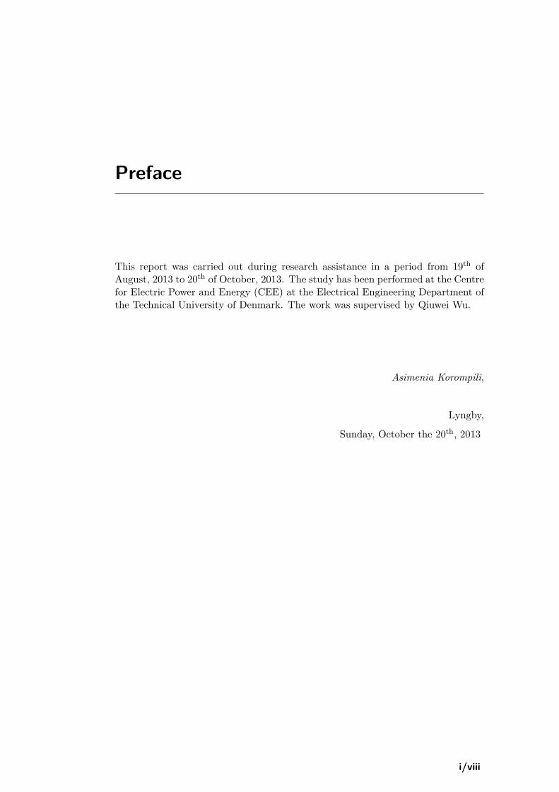
In Europe, an increasing number of offshore wind farms have been constructedor proposed, especially in the areas of North and Baltic Seas, where wind energyresources are rich and widely distributed. Figures 1.1a-1.1b present the growth ofwind power capacity installed and energy produced by wind in the EU, for bothonshore and offshore locations, from 1990 and projected till 2030. As it can beobserved, by 2030 the total wind power capacity will be 400 GW, out of which150 GW will be installed in offshore sites. However, due to higher capacity factor ofthe offshore wind farms, the latter will produce half of the total energy [1, 3, 6, 7].Moreover, Figure 1.2 illustrates the worldwide trend of future offshore wind farmsfor being of higher power capacity, as well as in increased distances from the shore[4, 5].
Therefore, there exists a clear need to further develop the power transmission tech-nology for connecting large wind farms, located in a long distance from the shore,to the nearby on-land network. Various transmission options should be analysedand investigated in terms of cost, as well as of stability and security of the powersystem [1, 2, 5].
1.3 High voltage grid connection of offshore wind farms
The transmission of high power over long distances creates challenges for the net-work operator and the wind farm developer.
As it is known, the electric power is the product of current times voltage. For agiven amount of power, low voltage requires high current and vice versa, i.e. highvoltage requires low current. When transmitting power through metal wires, a smallamount of power is lost as heat in the wires. This power loss is given by Joule’sfirst law and it is proportional to the square of the current. Thus, for a specificamount of power, the power loss will be greater in systems with high current (and
2/103
1.3. High voltage grid connection of offshore wind farms
(a) Installed wind power capacity (cumulative figure) [6]
(b) Wind energy production [3]
Figure 1.1: Growth of wind power capacity and energy production in EU
Figure 1.2: Trend of future offshore wind farm:installed capacity vs distance from shore [5]
3/103

1.4. HVAC vs. HVDC transmission technology
low voltage) than in the systems with low current (and high voltage). As a result,for reducing power losses in transmission systems, and considering the constraintsof practical conductor size, high voltage is used [8, 9].
There are two alternative methods, both in high voltage, for connecting offshorewind farms to the grid: high voltage AC (HVAC) and high voltage DC (HVDC)systems. The selection of the suitable transmission type should be done by takinginto consideration power efficiency as well as economical aspects [2, 10].
1.4 HVAC vs. HVDC transmission technology
In this section the two alternative transmission systems are going to be compared.The advantages of the HVAC transmission method, which are analysed in 1.4.1, ex-plain its dominance in the power system up until now. However, its disadvantages,which are given in 1.4.2, led engineers to developing new transmission technolo-gies based on DC links. The resulted higher technical and economical feasibility ofHVDC connections give reason for their increasing use in the future. Their advan-tages are analytically presented in 1.4.4, which enable the applications of HVDCsystems described in 1.4.5.
1.4.1 Dominance of HVAC transmission systems
In the late 19th century, during the initial years of electricity usage, transmissionand distribution of electric energy were achieved through DC systems. However,they were found to be inefficient due to power losses in conductors. The voltagedrop in the resistance of conductors was so high that power plants should be locatedwithin a mile from the load. In addition, converting DC from one voltage level toanother required a large converter, which was expensive, inefficient and neededmaintenance. As a result, higher voltage levels could not so easily be used, sincethere was no low-cost technology that would allow reduction of a high transmissionvoltage to a low utilisation voltage [8, 11].
The power losses in conductors and the difficulty in voltage conversion in DC sys-tems were the key factors to the success of the AC systems and their dominance inthe transmission and distribution of electric power. In AC systems, power could betransmitted more efficiently over long distances with far less power losses. Simpleand efficient transformers, which have no rotating parts and therefore require verylittle maintenance, were used to down step high transmission voltage to low distri-bution voltage. These practically mean that fewer and larger power plants couldserve the load in a wider area. Hence, AC technology was accepted as the onlyfeasible method for transmission and distribution of electrical power [8, 11–13].
As a result of the dominance of AC power, HVAC transmission systems offer, upuntil now, a simple and cost-efficient solution for bulk power transmission andreliable integration of large-scale renewable energy sources. Most of the presentlarge offshore wind farms are grid-connected through HVAC transmission systems.For example, "Thanet offshore wind farm", the largest offshore wind farm to datewith total capacity of 300 MVA, is grid-connected via HVAC cables. The "HornsRev I" offshore wind farm (160 MW) in the North Sea is connected to the nearest
4/103

1.4. HVAC vs. HVDC transmission technology
suitable 150 kV on-land substation through a 57 km long, 150 kV AC cable (21 kmof submarine cable and 36 km of onshore cable). The "Horns Rev II" offshore windfarm (209 MW) is grid-connected utilising an almost 100 km long, 150 kV AC cablesystem, consisting of submarine and on-land cable sections [3, 5, 7].
1.4.2 Disadvantages of HVAC transmission systems
As explained above, important equipment aspects have been the key factors indeciding the use of an AC system up until now. Nevertheless, an AC system hasits own associated bottlenecks, concerning mainly reactive power requirements andlimitations of the cable transmission distance [5].
The reason of the restricted transmission length is the power losses in the cables orlines used. When AC systems are applied in cables, additional current should flowthrough the cable to charge its capacitance. This extra current flow increases thetemperature of cable conductors, resulting in energy losses as heat. The reactivecurrent generation increases with the rated voltage and the length of the cable. Thiscapacitive effect of underground or undersea cables applies also to overhead lines,although to a shorter extent. However, in long AC overhead transmission lines theneeded current for the capacitance charge could be significant. In any case, theentire current-carrying ability of the conductor could be needed only to supply thecharging current. This practically means that the capacitive effect limits the power-carrying ability of AC cables and long lines [4, 8, 9, 13–15]. In cases where overheadlines are used, the useful current-carrying capability of the transmission system isfurthermore reduced due to the skin effect: line conductor presents high resistanceto alternating current, which causes a non-uniform distribution of the current overthe cross-sectional area of the conductor. This issue is of practicable significancein the case of large conductors carrying thousands of amperes [3, 4, 8, 9, 13]. Inaddition to losses, the AC cable costs also increase rapidly with the transmissiondistance [2].
Consequently, the reactive current, drawn by the cable capacitance, forces reactivepower compensation measurements. As mentioned above, the reactive power gen-eration of HVAC cables increases with both voltage level and cable length and leadsto sub-optimal utilisation of their inherent current-carrying capability. In general,long HVAC lines exhibit a wide variation in reactive power flow from peak loadto light load conditions and, if the system is weak, this can result in operationalproblems. Such long lines can be the cause for voltage collapse situations and "low-voltage fault ride-through" requirements, derived from the grid codes, are difficult tobe achieved. Thus, reactive power control devices may be required at both sendingand receiving ends of the HVAC link, depending on the relative strength of the ACsystem at the connection point, for regulating reactive power and therefore avoid-ing voltage stability problems. In some cases, additional dynamic reactive powercontrol devices, such as SVCs or STATCOMs, may be necessary [2–4, 7, 10, 16].
In conclusion, the usage of HVAC systems for bulk power transfer over long dis-tances is not preferable. As far as the grid connection of renewable energy sourcesis concerned, the current offshore wind farms, which are located in relatively shortdistances from the coast, acquire HVAC transmission technology, but for longerdistances the suitability of HVAC transmission is questionable [5].
5/103

1.4. HVAC vs. HVDC transmission technology
1.4.3 Development of HVDC transmission systems
The aforementioned drawbacks of HVAC transmission systems led engineers todeveloping HVDC transmission methods as a supplement to the current HVAClinks. In recent years, the rapid development of power electronics gives to theHVDC technology the opportunity to overcome its former bottlenecks and becometechnically and economically feasible for power transmission over long distances[1, 11]. Indeed, the invention of power electronic devices such as thyristor valves andrectifier improved reliability and efficiency of conversion between AC and DC. Thus,the design and development of current-source converters (CSC) became practicallypossible. In the next years HVDC transmission systems based on thyristors, whichare called classic HVDC systems, have been proved to be feasible on an industrialscale [1, 5, 8, 11, 17]. The world’s first commercial HVDC transmission link wasbuilt in 1954, connecting the island of Gotland in the Baltic Sea to the Swedishmainland via a submarine 20 MW cable. Ever since, the classic HVDC transmissiontechnology has been developing to become mature and well-proven [1, 4, 11, 14, 15].
Recently the next-generation type of HVDC transmission systems has become avail-able. It is based on the more advanced semiconductors technology, namely the in-sulated gate bipolar transistors (IGBTs). The invention of IGBTs has acceleratedthe development of voltage-source converters (VSC), which have come into use inthe last years in HVDC applications in lower power ranges [1, 5, 11, 13–15, 17].Since its first commercial application in 1999 in an undersea 50 MW, 80 kV link, theVSC-HVDC technology has been developed regarding losses reduction and voltageand power ratings increase. The evolution of IGBTs has reduced switching andconduction losses through more optimised components and schemes. In addition toswitching patterns, development in converter topologies also reduce power losses.The evolution of losses and capacity in voltage-source converters can be seen inFigure 1.3. Apart from the converter development, cable technologies have alsoadvanced, through research in extrusion methods and cable accessories (joints, ter-minations), resulting in higher link capacities. This has enabled HVDC applicationsto expand in voltage and power levels, supporting the grid in increased demand ofsecurity [18].
Figure 1.3: Evolution of station losses and power capacity in VSCs [18]
6/103

1.4. HVAC vs. HVDC transmission technology
1.4.4 Advantages of HVDC transmission systems
For power transfer over long distances, the prospect of DC systems is consideredvery attractive due to the limitations of AC cable systems, as described in 1.4.2.Indeed, in DC technology there is no additional reactive current required for charg-ing the cable capacitance; the capacitance is charged only when the cable is firstenergized or if the voltage level changes; during the static condition the cable actsas a resistor. Thus, the power-carrying capability of the DC cables and long linesis not restricted by the capacitive effect. This also means that there is no needfor reactive power compensation for absorbing the excessive reactive current in thecable or line. Moreover, the line conductors operating with DC do not suffer fromthe constraint of the skin effect, as AC lines do. As a result, cables and overheadlines can carry more current to the load when operating with DC than AC, sincethe power losses per transferred MW over the transmission distance are less. [19]mentions that HVDC systems can carry 2-5 times the capacity of an AC line oper-ating at the same voltage. This implies that DC transmission systems can increasethe capacity of an existing power network, which is important especially in situa-tions where additional wires are difficult or expensive to be installed. In additionto the increased power-transfer capability, the reliability of HVDC links at electri-cal disturbances is found to be enhanced, compared to that of HVAC connections[2–6, 9–11, 13–16, 20].
However, in HVDC systems the power losses in the converter should also be takeninto account. On the contrary, in HVAC systems the only components which couldcontribute to power losses are the transformers and the compensating reactors;nevertheless, the major amount of power is lost in the transmission cables, so thatthe losses in the other modules could be assumed as negligible [5, 6, 9, 11].
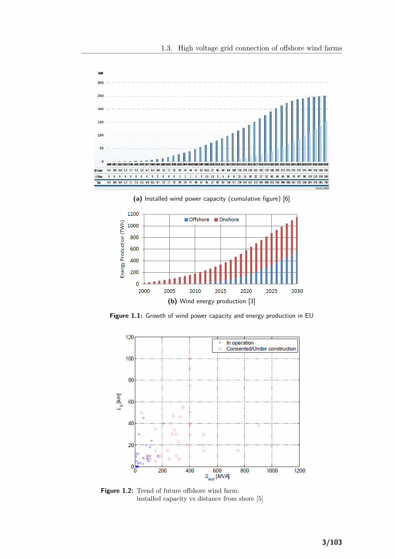
In Figure 1.4 a comparison of power losses in HVAC and HVDC systems withincreasing transmission distance is illustrated. At zero transmission distance, thepower losses occur only in the other equipment apart from the cables. Thus, thelosses in the converter of HVDC systems dominate. However, in HVAC systemspower losses increase more rapidly with increasing transmission distance than inHVDC systems (higher slope of curve in Figure 1.4). As a result, above a certaindistance, the "break-even" distance, the HVDC alternative presents always lowerpower losses and below this specific distance HVAC technology has lower losses[6]. [5] concludes that, for medium-scaled power transfer, the HVAC technologyprovides more efficient solution for distances below 90 km, while HVDC systemsare more preferable for longer distances, above 110 km. In case of higher amountsof power (> 500 MVA), [5] expects that HVDC systems will provide an even furtherefficient transmission solution, since they will present less power losses than HVACsystems at shorter distances.
Although total system power losses is one of the major factors, the process ofdecision between HVAC or HVDC transmission systems should also include manyother factors, such as investment costs and operation and maintenance costs. Theterminal stations are more expensive in the HVDC case due to the conversionequipment. However, HVDC transmission lines and cables cost less than in HVACsystems for the same capacity over long distances. This relies upon two factors:firstly, HVDC systems need fewer conductors, since there is no need for three wiresto support three phases, but only for two for the two polarities; secondly, thinner
7/103
1.4. HVAC vs. HVDC transmission technology
Figure 1.4: Power losses with transmission distance in AC and DC systems[6]
conductors can be used, since they do not suffer from the skin effect as AC lines.These can lead to large savings in transmission system costs. In addition, landacquisition/right-of-way costs, as well as operation and maintenance costs, are alsolower in the HVDC case. Short schedules for manufacturing, transportation andinstallation minimise also the financial cost. Generally speaking, the relative cost ofHVDC transmission systems is going to be further reduced, since their componentsbecome cheaper due to continuing innovative technological developments in thefield of power electronics [2–6, 9–11, 13–16, 21].
In Figure 1.5 a cost comparison between HVAC and HVDC lines with increasingtransmission distance is presented. At zero transmission distance the terminal cost(converter equipment cost) dominates, making HVAC systems more cost-efficient.The curve of DC costs is not so steep as the curve for the AC costs, since linecosts per kilometre are lower in HVDC systems. The total costs in both cases areeven higher if capitalised value of losses is taken into account. For long AC lines,the cost of losses is quite high due to reactive power compensation costs whichshould be included. Thus, above the "break-even" distance the total cost is higherfor the HVAC technology, making HVDC transmission systems more preferable.The "break-even" distance is in the range of 500 − 800 km, usually around 600 km,and it depends on cost of right-of-ways, loss evaluation, interest rates for financing,country-specific cost aspects and other factors [6, 11, 13]. In the case of subma-rine cables, HVDC systems provide an even more cost-effective solution, since the"break-even" distance is much smaller (less than 100 km, typically about 50 km)[11].
Hence, by taking into account the increase in power losses and cost with increasingdistance in the two alternative transmission systems, HVDC solution is found tobe more attractive for the transmission of bulk power over long distances. Fur-thermore, HVDC technology may also be selected because of additional technicalbenefits which can provide to the power system.
HVDC transmission systems do not contribute to the short circuit current of theinterconnected AC system and therefore do not increase fault levels, contributingto the stabilisation of the power system [9, 11, 16, 22].
Moreover, HVDC systems can transfer power between separate AC networks, which
8/103

1.4. HVAC vs. HVDC transmission technology
Figure 1.5: Cost with transmission distance in AC and DC systems [13]
are difficult to be connected due to stability reasons or even operation at differentnominal frequencies (50 and 60 Hz). Since power transfer can occur in both di-rections, it increases the stability of both networks, by allowing them to exchangepower with each other in emergencies and failures. Disturbances in one networkwould not affect the DC link and therefore the HVDC connection system preventscascading failures from one AC system to the other. This ability implies AC/ACdecoupling between the two power systems, so that transient conditions in one net-work do not affect the stability of the other. In other words, DC links insulate oneAC network from the others. However, they offer the opportunity of adjusted powerexchange, so that connected AC systems would contribute to the stabilisation ofone failure-affected AC network [2–6, 9–11, 13–15, 22].
This ability of DC links becomes possible due to the fundamental advantage ofHVDC transmission systems, i.e. their controllability: HVDC converters can con-trol easily the active power flow through the link [5, 11, 14, 15]. In cases wherepower exchange has been agreed between two AC networks, HVDC systems cancontrol the power flow through the tie links at all times, by automatically keepingthe arranged pre-set value of power flow, i.e. the transmitted power is not dictatedby the phase angle differences between the two AC networks. Even in a contin-gency event at one of the AC networks, the HVDC connection can be forced toadapt the power flow, which can support the troubled grid. Moreover, the trans-mission link becomes never overloaded, so that it is not led to disconnection andthe fault condition does not spread to a wide area [16, 20, 22]. This also meansthat HVDC connections can be rated only for scheduled power transactions andagreed emergency support; therefore, they are more economically attractive thanthe HVAC links, whose capacity should be many times higher than the capacityneeded for scheduled power transfers in the steady state [16]. The control systemof the HVDC converter, as well as the capabilities that offers to the transmissionsystem, will be described in Chapter 3.
The power exchange between interconnected AC networks could lead also to reducedpollution levels and increased fuel economy, since expensive and polluting peak-power generation in one network can be replaced by cheap and renewable-basedpower from another network [12].
9/103

1.4. HVAC vs. HVDC transmission technology
1.4.5 Applications of HVDC transmission systems
Up until now, HVDC systems have been widely used for point-to-point power trans-mission over long distances or connection between two AC grids [9, 14–16, 19, 21–23]. For instance, in the mid 80’s Quebec was interconnected with the powernetworks in New England and New York via four HVDC stations and one trans-mission line [14–16]. DirectLink in Australia connects the regional electricity mar-kets of Queensland and New South Wales through a 60 km, 180 MVA HVDC cable.Similar to this, Murraylink connects the electricity markets of Victoria, New SouthWales and south Australia and operates as a generator by participating in the spotmarket [20]. Several HVDC links are also in operation or in schedule, connectingthe AC networks of countries in Scandinavia and continental Europe; therefore,a new HVDC grid for power exchange has been formed, as shown in Figure 1.6[9, 23]. These interconnections through HVDC links improve effectively the trans-fer capability between regional networks. This was found to be of great importanceespecially in the latest years, since the AC tie lines are frequently fully loaded,restricting the economic power transfer between adjacent regions [19]. They en-hance also the stability of the interconnected networks, by preventing outages orlimiting the consequences of major disturbances, as explained in 1.4.4. An exampleof this capability of HVDC links occurred in the Scandinavian network, where theAC grids of Sweden and Norway are connected to the grid of Denmark throughthe Skagerrak link. On a contingency occasion, two 1000 MW nuclear stations inSweden were disconnected and the frequency dropped to 48.5 Hz. At the time ofthe event the Skagerrak link was exporting its rated power (500 MW) from Norwayto Denmark. When the frequency drop was detected, the power direction reversedand 500 MW were injected into the norwegian/swedish grid (a net contribution of1000 MW) [22].
For transferring large amounts of power, up to 6000 MW, over very long distances,above 1000 km, ultra-HVDC links, i.e. systems at voltages above the highest in use(600 kV), have also been developed, since they are found to be economically moreattractive. With few structure changes and proper control, protection and auxiliarysystems, the reliability and availability of such links could be better than these ofsystems at lower voltages [24, 25]. Such a transmission system has recently been gotinto operation in the 800 kV, 6400MW, 2000 km Xiangjiaba-Shanghai connectionin China, designed and installed by ABB [14, 15, 25].
In some connections combination of a DC link in parallel with an AC network canalso be used, as described in [14, 15, 25]. In these cases the bulk power is transferredvia the HVDC system and the power needed from AC networks along the route isfed by the HVAC system. This hybrid transmission system is found to be the mostcost-effective and flexible option for dealing with the drawback of HVDC systemsthat power tapping along the line is expensive [25]. In addition, the power in DClinks can be controlled and automatically adapted to protect the parallel AC linesfrom being overloaded [14, 15, 22]. An example of such a hybrid system is theparallel operation of the Pacific HVDC Intertie and the AC network between theareas of Oregon and Los Angeles in the western USA [22].
In the opposite direction of AC networks interconnection, HVDC technology can beapplied for decomposing large power systems into smaller, asynchronously operatedsections, interconnected exclusively by DC links. In such DC segmented grids,
10/103

1.4. HVAC vs. HVDC transmission technology
Figure 1.6: HVDC links in Europe [9]Red: existing links, Green: links under construction,Blue: proposed links
risks that exist in large AC networks, such as cascading of disturbances, transfercapability limitations and expansion restrictions, do not any more occur. In thisway the reliability of the power system is enhanced [14, 15, 19, 22]. An exampleof such a HVDC grid is the North American Power Transmission Network: itis subdivided into five asynchronous regions that are connected through HVDCtransmission links and stations. In total there are eight HVDC links and twelveHVDC stations for connecting the north-american regions. Some of the HVDClinks are operating entirely within one region, in parallel with the conventional AClines, while others connect two asynchronous networks [16].
DC links can also be used for directly feeding large urban areas, where there are highload densities, whereas simultaneously strict requirements for reliability and powerquality have to be met. Apart from point-to-point systems, where power is directlydelivered to in-city loads, there could be multi-terminal HVDC networks embeddedin a city grid. Figure 1.7 presents such a DC network, where power is importedradially from outside sources and distributed through a DC ring to the inverterstations located at different load positions. Instead of multi-terminal systems witha DC ring topology, another scheme can be developed, with a closed loop at theAC circuit, for not increasing the short circuit power [19, 21]. These multi-terminaltopologies are described in details in 2.6.2. For avoiding the difficulties to obtainright-of-way permit for new overhead lines in large and dense urban areas, there isthe possibility of upgrading an AC line to a HVDC one. The conversion could bedone in many ways, depending on the configuration of the existing line. So far, thisprocedure has been implemented in a few cases, but it is attracting considerableinterest, while several applications are being studied [16]. Anyway, even if thisconversion is not applicable, laying underground DC cables is a much easier, quicker
11/103

1.4. HVAC vs. HVDC transmission technology
Figure 1.7: DC grid feeding city network [19]
and cheaper procedure than for building overhead AC lines. Cables rarely meetpublic opposition, since they do not change the landscape and their electromagneticfield is lower and static. Thus, HVDC systems are ideally suited for poweringmetropolitan areas [12, 20].
On the other side, HVDC transmission systems are also useful for connecting re-mote loads, such as islands, mining areas, gas and oil fields or drilling platforms. Inthis way, building a local power plant based on fossil fuels is avoided. This approachleads to costs reduction, higher operation efficiency and GHG emissions minimi-sation [12, 14, 15, 18, 21]. The first installation powering an offshore platformcomprised of a 70 km subsea HVDC link, for power transfer from hydro resourcesin Norway to two compressors at the Troll A oil and gas platform in the North Sea[14, 15, 18].
Today, an emerging application area for the HVDC transmission technology is therenewable energy resources integration to the power system. A large part of theseresources is located in remote areas (at sea, in desert or in unpopulated areas) andthe utilisation of their huge power potential is to a considerable extent a matterof power transmission technology. Their use often requires the construction of newpower networks affecting the existing grids of several regions [14, 15]. For instance,Itaipu HVDC link in Brazil transmits power (6300MW) from remote hydroelectricplants to the Itaipu region for more than 20 years. Two other HVDC links inBrazil connect hydroelectric power plants in the Amazon area to country’s mainload centres in Rio Madeira and Belo Monte, respectively, both located more than2000 km away [26]. Several projects have also been proposed or already constructedfor transferring power from offshore wind farms in North and Baltic Seas, hydropower plants in Scandinavia and solar power plants in northern Africa through adeveloping HVDC grid to large load centres in the central Europe.
In the specific case of the grid connection of large offshore wind farms located in longdistances from the coast, HVDC systems are commonly considered as the optimalmethod and their increasing use in many new projects worldwide has challengedthe market dominance of HVAC transmission technology. One of the world’s mostremote wind farms in the North Sea, "BARD offshore 1", with total installed ca-pacity of 400MW, is connected through a 200 km VSC-HVDC cable to the coastal
12/103

1.4. HVAC vs. HVDC transmission technology
network in Germany. The wind farm is commissioned in 2012 and is scheduled tobe in operation during 2013 [5, 14, 15, 18, 19]. Several other HVDC links are un-der development for the grid connection of large offshore wind farms in the NorthSea, like BorWin-II, DolWin-I and DolWin-II, HelWin-I. Similar projects are alsodeveloped in many countries worldwide, such as in UK, Canada, USA and China[1, 3, 4, 7, 17, 18]. For example, the Atlantic Wind Connection in the mid-atlanticregion of USA consists of an offshore HVDC transmission system, of 7000MWcapacity, with multiple delivery points on the mainland grid [18].
13/103

1.4. HVAC vs. HVDC transmission technology
14/103
Chapter 2
HVDC transmission systems
The first HVDC system came into operation 50 years ago. Since then many HVDCtransmission schemes have been developed. In this chapter the development ofthese systems is described. The system structure is given and its components areanalysed. Research activities for new technologies are also presented. The mostmodern transmission method, i.e. VSC-HVDC, is applied in the grid connection ofoffshore wind farms. Finally, various system configurations and topologies for thistransmission scheme are provided.
2.1 Classic HVDC transmission system
The HVDC system is made up of a number of equipment. In Figure 2.1 the maincomponents of the classic HVDC transmission system are depicted. The stationrequires considerable big area of land, since transformers, filters and auxiliary ca-pacitors are located outdoors. The valves converter and the control equipmentare placed in a closed air-conditioned and air-heated building. However, it shouldbe borne in mind that the enclosed systems require high spatial distribution andtherefore a large building, which is too expensive [11].
In the followings the main modules are described, concerning their role in the wholesystem, their structure and operation, as well as the latest trends in their technicaldevelopment.
2.1.1 Converter
The converter is the most important module, since it performs the conversion fromAC to DC (rectification) at the sending end and from DC to AC (inversion) atthe receiving end of the DC link. The converter of classic HVDC systems is basedon thyristor valves. Thyristors require connection with an external AC circuit toturn on and off. This means that, in conventional HVDC transmission systems,the connected AC power system provides the means of commutating the current tothe valves in the converter. This is the reason for which converters in the classic
15/103

2.1. Classic HVDC transmission system
Figure 2.1: Classic HVDC transmission system [27]
HVDC systems are known as line-commutated converters (LCC). Such convertersrequire rotating synchronous machines in the connected AC system and thereforecannot be connected to passive loads [9, 17, 19, 28].
Due to high voltages in HVDC systems, which far exceed the breakdown voltageof the thyristors, large numbers of them are usually connected in series, buildingone unit. For ensuring the even share of voltage between the thyristors of such aunit, each thyristor is connected in parallel with additional passive components,such as grading capacitors and resistors. The complete switching unit, consistingof series-connected thyristors with their auxiliary circuits, is referred to as a valveand each thyristor with its grading circuits and the other auxiliary equipment isknown as valve branch or thyristor level [9, 13].
The basic converter configuration for classic HVDC systems uses a three-phasebridge, also called 6-pulse bridge, since it contains six valves, each connecting oneof the three phases to one of the two DC rails. This converter unit is illustrated inFigure 2.2a. However, this arrangement produces considerable harmonic distortionat AC and DC sides, since the phase changes only every 60◦. For enhancing thisarrangement, a 12-pulse system, shown in Figure 2.2b, has become standard on mostLCC-HVDC systems. A 12-pulse circuit is a serial connection of two 6-pulse bridgeswhich are connected separately to the AC network through two transformers. Oneof these is configured to have a star secondary (Y-Y winding structure), while theother a delta secondary (Y-∆ winding structure). In this way, a phase difference of30◦ is established, cancelling the six-pulse harmonics and reducing the distortion:fifth and seventh harmonics at the AC side are eliminated, reducing significantly thecost of harmonic filters; sixth and eighteenth harmonics are eliminated at the DCside, reducing the DC voltage ripple. Converters with more than two bridges arealso possible (three-bridge or 18-pulse converter, four-bridge or 24-pulse converter),leading to even less harmonic distortion. Nevertheless, the required transformerconnections are getting more complex and therefore it is more practical to use a12-pulse converter and provide the necessary harmonic filters [9, 11, 13, 17, 28, 29].
HVDC systems with a single 12-pulse converter per pole are in commercial op-eration in several projects demonstrating excellent performance. Based on this
16/103

2.1. Classic HVDC transmission system
(a) Six-pulse bridge [17]
(b) Twelve-pulse bridge [13]1: Valve, 2: Double valve,
3: Valve tower, 4: Six-pulse bridge
Figure 2.2: Converter bridges
experience, such configurations could be used in applications of 3000-4000MW at800 kV. For higher power ratings, above 4500MW, at 800 kV two series-connectedor parallel-connected 12-pulse converters per pole should be used, as shown in Fig-ure 2.3. These configurations, with the two converter groups per pole, increasereliability and availability of the transmission system, since in an outage of oneconverter only one quarter of power is lost. In addition, the division of converterinto more groups helps the transportation of converter transformers, consideringtheir size and weight [25, 26, 30].
Figure 2.3: Series/Parallel-connected twelve-pulse converters [25]
In LCCs, the DC current cannot usually change direction. At the AC side, theconverter behaves as current source, injecting current to the AC network. Hence,such converters are also known as current-source converters (CSC) [9].
2.1.2 Transformers
The converter transformers, often three physically separated single-phase trans-formers, transform the voltage of the AC busbar to the required entry voltage ofthe converter. In this way, they isolate the converter station from the AC system,
17/103

2.1. Classic HVDC transmission system
providing a local earth, and ensure the voltage insulation, to make possible theconnection of converter bridges in series at the DC side. The main insulation ofthe transformer in the valve-side winding is subject to the combined load stress ofboth AC and DC voltage. For ensuring the correct valve voltage, the transformersare equipped with tap-changers [9, 13].
The transformers in LCC-HVDC systems are quite specialised, due to high levelof harmonic currents flowing through them. The design of the insulating structureinside the tank is also affected, since the valve-side winding experiences a permanentDC current, requiring more solid insulation. In addition, the transformers in thesetransmission schemes should provide the 30◦ phase shift for the cancellation ofharmonics [9, 13].
2.1.3 Reactive power supplies
In LCC-HVDC systems the converter inherently consumes reactive power. Indepen-dent of the direction of the active power flow, the current flowing into the converterfrom the AC system lags behind the AC voltage, meaning that the converter al-ways absorbs reactive power. The amount of reactive power absorbed is at least50% of the active power transmitted in steady-state conditions. Under transientconditions, the amount of reactive power needed can be much higher. Faults inthe AC network at the inverter side of the transmission system will cause the cableto discharge, resulting in voltage collapse in the AC network. The inverter shouldcounteract the increased transient current by increasing each own terminal voltage.This implies increased need for reactive power. Therefore, reactive power sourcesare required close to the converters. When the converter station is connected di-rectly to power stations, an amount of the reactive power can be provided by thegenerators themselves. In most cases, however, other reactive power compensationdevices should be applied to the HVDC system. These devices can be connectedto the network in series or in shunt connection. Shunt compensation devices areapplied for voltage control, whereas series compensation is employed to control thelongitudinal behaviour of the power system. Any surplus or deficit in reactive powerfrom these local supplies should be accommodated by the AC network. The unbal-ance in reactive power should be kept within a given range, in order to maintainthe AC voltage in a desired tolerance. This implies that the weaker the AC systemis, the tighter the reactive power exchange should be, for keeping the voltage withinthe required band [9, 28, 29, 31, 32].
2.1.3.1 Shunt reactive power compensation
The most common reactive power compensation devices are in the form of shuntcapacitor banks connected at the AC terminals of the converter. They can beconnected directly to the grid voltage or to a lower voltage through a tertiarywinding of the converter transformer. The shunt capacitors are usually grouped inswitchable banks (typically four per converter), so that the appropriate amount ofreactive power is supplied to the system, according to active power transferred (thereactive power consumed by the converter depends on the active power transmittedby the system). In this way, a surplus of reactive power is prevented in cases of lowpower transmission [9, 29].
18/103
2.1. Classic HVDC transmission system
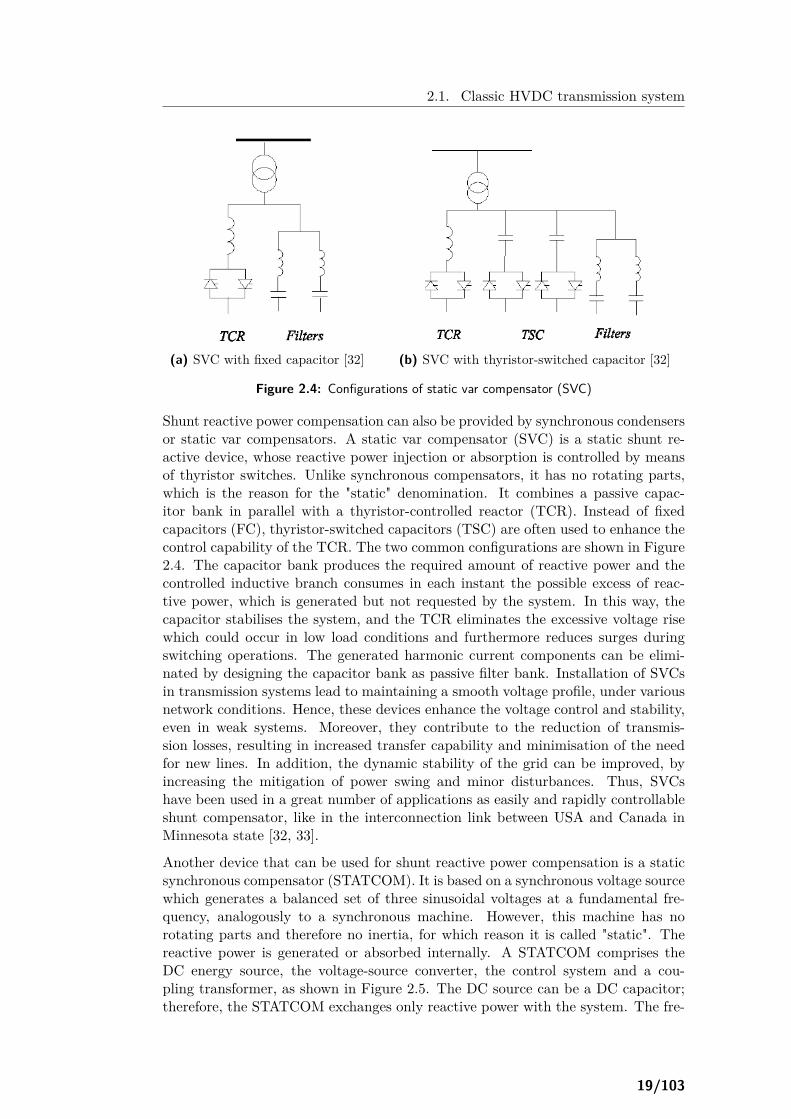
(a) SVC with fixed capacitor [32]
(b) SVC with thyristor-switched capacitor [32]
Figure 2.4: Configurations of static var compensator (SVC)
Shunt reactive power compensation can also be provided by synchronous condensersor static var compensators. A static var compensator (SVC) is a static shunt re-active device, whose reactive power injection or absorption is controlled by meansof thyristor switches. Unlike synchronous compensators, it has no rotating parts,which is the reason for the "static" denomination. It combines a passive capac-itor bank in parallel with a thyristor-controlled reactor (TCR). Instead of fixedcapacitors (FC), thyristor-switched capacitors (TSC) are often used to enhance thecontrol capability of the TCR. The two common configurations are shown in Figure2.4. The capacitor bank produces the required amount of reactive power and thecontrolled inductive branch consumes in each instant the possible excess of reac-tive power, which is generated but not requested by the system. In this way, thecapacitor stabilises the system, and the TCR eliminates the excessive voltage risewhich could occur in low load conditions and furthermore reduces surges duringswitching operations. The generated harmonic current components can be elimi-nated by designing the capacitor bank as passive filter bank. Installation of SVCsin transmission systems lead to maintaining a smooth voltage profile, under variousnetwork conditions. Hence, these devices enhance the voltage control and stability,even in weak systems. Moreover, they contribute to the reduction of transmis-sion losses, resulting in increased transfer capability and minimisation of the needfor new lines. In addition, the dynamic stability of the grid can be improved, byincreasing the mitigation of power swing and minor disturbances. Thus, SVCshave been used in a great number of applications as easily and rapidly controllableshunt compensator, like in the interconnection link between USA and Canada inMinnesota state [32, 33].
Another device that can be used for shunt reactive power compensation is a staticsynchronous compensator (STATCOM). It is based on a synchronous voltage sourcewhich generates a balanced set of three sinusoidal voltages at a fundamental fre-quency, analogously to a synchronous machine. However, this machine has norotating parts and therefore no inertia, for which reason it is called "static". Thereactive power is generated or absorbed internally. A STATCOM comprises theDC energy source, the voltage-source converter, the control system and a cou-pling transformer, as shown in Figure 2.5. The DC source can be a DC capacitor;therefore, the STATCOM exchanges only reactive power with the system. The fre-
19/103

2.1. Classic HVDC transmission system
Figure 2.5: Static compensator [32]
quency, amplitude and phase of the AC voltage (converter output), and thereforethe reactive output of the converter, can be properly controlled. If the convertervoltage is higher than the voltage at the coupling point, the STATCOM injectsreactive power to the AC system; if the converter voltage is lower than the voltageat the coupling point, the STATCOM absorbs reactive power. Hence, by propercontrol STATCOMs can contribute to voltage variations reduction, enhancing dy-namic voltage stabilisation and steady-state voltage support. In this way, powertransfer capability increases and power system damping is also improved, meaningincreased transient stability and dynamic load balancing. In general, the overallpower quality is enhanced [32].
In the latest years a new generation of SVC has been developed, consisting of aSTATCOM with an IGBT voltage-source converter, as illustrated in Figure 2.6.The basic operation principle of the VSC-based SVC is the generation of a three-phase symmetric voltage with desired frequency. The control concept is the sameas in a STATCOM device, as depicted in Figure 2.6. If the VSC voltage is phased-advanced from the network voltage, active power is injected by the converter tothe network; if the VSC voltage is phase-delayed concerning the network voltage,then active power flows from the network towards the converter. In this way theDC voltage can be controlled: when the DC voltage is below its setpoint, the VSCvoltage is controlled to be phase-delayed, for creating active power flow towardsthe converter; when the DC voltage exceeds its desired level, the VSC voltage iscontrolled to be phase-advanced, for transferring active power from the converterto the network. The voltage amplitude is also controlled to regulate the reactivepower flow: if the VSC voltage has higher amplitude than the network voltage,the compensator delivers the needed reactive power to the network; if its voltageamplitude is lower than the amplitude of the voltage at the connection point, theconverter will consume reactive power, acting as inductor [33]. The VSC operationis determined by the maximum voltage on the converter terminals and the maximumconverter current; by taking into account these two limits, under-voltage and over-voltage conditions can be dealt with. Moreover, the DC link in a SVC systemis not connected externally and hence the DC voltage level can be freely selectedat an optimal value regarding VSC’s economies. Another advantage is the shortresponse time: the semiconductor valves can respond almost instantaneously andtherefore the only limiting factors for the response speed are the time for processingvoltage measurements and control procedures. A response time shorter than a
20/103

2.1. Classic HVDC transmission system
Figure 2.6: Configuration and control principle of VSC-based SVC [33]
quarter of a cycle is nowadays achievable. In addition, the transmission systemcan be designed without harmonic filters. The high switching frequency resultsin an inherent capability of producing voltages at high frequencies. By injectingharmonic currents into the network with proper phase and amplitude, this propertycan be used for counteracting and therefore filtering harmonic voltages alreadypresent in the power system. The reduction of equipment needed leads also to amore compact layout, decreasing thus the converter station costs. Up until now,ratings of around 100Mvar per converter are available; when higher reactive poweris required, an assembly of more than one converter can be used or additionaldevices, such as fixed capacitors or thyristor-switched capacitors, can be applied[32, 33]. The introduction of IGBT-based SVCs for reactive power compensationin the classic LCC-HVDC transmission system led to the development of a newconfiguration of transmission systems (Figure 2.7), based on VSCs (VSC-HVDC),which enables an advantageous system operation; this transmission system, as wellas its enhanced capabilities is described in the next section.
Figure 2.7: Development of VSC-HVDC transmission system [34]
2.1.3.2 Series-connected reactive power compensation
The introduction of synchronous condensers or switching reactive shunt banks in-creases the technical complexity, as well as investment and maintenance costs [31].As a result, the development of another configuration of the HVDC transmissionsystem was desirable. In the new design, capacitors are connected in series to thevalves. The choice of their location requires special study in each particular case,
21/103

2.1. Classic HVDC transmission system
Figure 2.8: Converter with series-connected capacitors [36]
taking into consideration the overall economy and system reliability. They are of-ten located in the line side of the converter transformer and switched as part ofthe lines [32]. However, [31, 35] propose their location to be between the convertertransformers and the valve bridge, in parallel with varistors for their over-voltageprotection (Figure 2.8). The main reason for selecting this position is that theoperating voltage across the capacitors is controlled by the converter. Hence, thecapacitor stresses are much lower. Furthermore, the transformer inductance limitsthe current in a fault case, meaning lower stresses for the varistor. Besides, if the ca-pacitors were located along the lines, there would be the risk of their asymmetricalcharging at AC system faults [31, 35].
There are several advantages of the configuration with series-connected reactivepower compensation, concerning the design of the transformer and valves. Firstof all, the phase-to-phase voltage at the valve side of the transformer is reduced,leading to reduced reactive power flow through the transformer. Thus, its ratingscould be decreased. Moreover, the total secondary-side impedance increases (byinserting the impedance of the series-connected capacitor), reducing transformerand valve currents during short circuits at the DC side. These lower current stressesallow the optimised design of transformer and valve, although implying higher valvevoltage ratings. The main benefit of the new configuration regarding the converteroperation is the leading phase shift that the series-connected capacitor introducesbetween the transformer secondary and the valves. This compensates the inherentlylagging characteristic of the converter; thus, the converter’s power factor can be keptto unity or even become leading [31, 35, 37].
Series-connected capacitors improve voltage control and reactive power balance,since reactive power generation in series-connected compensation increases withthe transferred power. Thus, the reactive power requirement becomes very lowand flat. Therefore, the need for capacitive shunt banks, switching in steps, iseliminated, leading to less cost of the transmission system. Low shunt compensa-tion leads to even larger transient advantages, i.e. lower over-voltages upon loadrejection. Another benefit regarding dynamic stability is associated with the factthat the commutation voltage results in positive inverter impedance characteristics.This means that when the DC current increases, the DC voltage at the inverterside of the classic HVDC system decreases due to a reduction in the AC networkvoltage, whereas in this new scheme it raises due to the capacitor voltage, whichoffsets the drop in the AC voltage. This helps in mitigating faults and implies alarge improvement in the inverter dynamic stability. This factor implies also stableoperation with low short-circuit ratios and better commutation failure immunity.
22/103

2.1. Classic HVDC transmission system
The latter is explained by the fact that the series capacitors act as an extra voltagesource for the commutation of the valves, in addition to the synchronous machinesof the AC system. This is the reason for which this design is denominated ascapacitor-commutated converter (CCC). Thus, the transmission system is able towithstand an AC voltage drop of 15-20%, while still preserving a sufficient com-mutation margin for stable operation and thereby maintaining constant DC powerflow during disturbances in the AC network. This advantageous behaviour can beobserved in Figure 2.9, where the response of the CCC-HVDC system in a remoteAC fault is compared to this of the conventional LCC-HVDC system. This meansimprovement in commutation performance and therefore minimisation of the riskof commutation failures. In general, the transient performance is found to be betterthan this of the conventional scheme, demonstrating a better damping characteris-tic. In addition, as a result of the increase in the transient stability limit, the powertransfer capability also increases [9, 28, 31–36, 38–41].
Figure 2.9: Behaviour of LCC-HVDC and CCC-HVDC systemsat a remote AC fault [34]
It should be mentioned, though, that voltage contribution of CCCs in the sys-tem can lead to increased harmonic production. The voltage from capacitors willsupport the commutation of the direct current from one valve to the other. Thisimplies that the overlap angle will be reduced, resulting in a somewhat higher ACharmonic currents. This, in combination with higher extinction voltage steps, leadsto increased harmonics at the DC side. The increased harmonic distortion can beof the order of 20% and can be dealt with by high performance filters at both ACand DC sides. This requirement is, however, offset by the smaller size of shunt-connected LC branches, due to less reactive power requirements [40]. In addition,although steady-state results determine CCC-HVDC superiority compared to LCC-HVDC, transient analysis concluded in non-uniformly favourable performance in along cable HVDC transmission system compared to the conventional scheme. Un-der balanced remote- and close-in faults the new scheme is found to be superior;however, with unbalanced disturbances the conventional system demonstrates bet-ter performance. This behaviour could be explained by the additional dynamicsdue to the energy storage in the series-connected capacitors of the CCC-HVDC sys-
23/103

2.1. Classic HVDC transmission system
tem: in cases of unbalanced faults, the voltage of each of these capacitors impactsthe system operation in a different extent. The performance of the CCC-HVDCtechnology under unbalanced contingencies should be therefore further investigated[41].
In recent years, the technology of series-connected compensation has undergonedramatic development, regarding the reliability of capacitors, as well as the controlsystems of the converter. For instance, the evolution in the control scheme ofCCC-HVDC is described in [42], where ordinary and advanced control systems arecompared. The new control scheme regulates the DC voltage, by keeping the ACvoltage constant at the connection point. In this way, not only the active powerflow is controlled through the converter, but also the reactive power exchange withthe network is managed for regulating the AC voltage at the connection point. Thisimplies that the inverter emulates the operation of a voltage-source converter. Thestudy results have shown that the connection of the inverter to a very weak ACnetwork becomes possible with the new control method: the HVDC transmissionexhibits very good recovery from faults in the system, without the risk of voltageor power instabilities, whereas it is unstable, when operating with the traditionalcontrol system [42].
Today, CCC technology has become well proved. In general, CCC-HVDC systemsare found to be a technically and economically beneficial solution, particularlyin cases of connection to weak AC networks, with low short-circuit capacity, or incases of very long transmission cables. Several HVDC transmission systems all overthe world operate according to CCC technology, like the Garabi interconnectionbetween Argentina and Brazil [32, 37].
With the development of thyristors, the usefulness of series-connected compensa-tion has been further augmented. The evolution of controllable series-connectedcompensation is depicted in Figure 2.10. Mechanically-switched series-connectedcapacitors (MSSC) offer flexibility of power flow control. However, the introductionof thyristors in thyristor-switched series-connected capacitors (TSSC) or thyristor-controlled series-connected capacitors (TCSC) brings the concept of this compen-sation concept even further [31, 32].
Figure 2.10: Evolution of controllable series-connected compensation [32]
24/103
2.1. Classic HVDC transmission system
The ratings of the TCSCs in the converter configuration are determined by severalfactors. The Mvar ratings depend on the overload requirements of the converter.The impedance of each TCSC depends on the requirement to maintain a constantimpedance as seen by the converter. TCSC converter has the same configuration asCCC, with the main difference of the location of the thyristor-controlled capacitor.In the case of CCCs, the capacitor is placed at the valve side of the transformer,as described above, since its placement along the AC line could lead to ferro-resonance problems. However, this issue does not occur with the thyristor controlof the capacitor. Thus, the position of the TCSCs is at the AC system side of theconverter transformer [31, 32]. In [31], different TCSCs positions are described,regarding additionally the location of the filters.
TCSCs offer many possibilities of control in the AC system. Supplementary to thetap changer of the transformer, TCSCs can contribute to controlling the steadystate DC voltage, the firing angles of the converter and the reactive power. Oneother potential benefit is the power balancing along the AC lines between the con-verter and the AC system. Apart from power flow control, TCSCs provide dampingof active power oscillations: the introduction of a time varying capacitive elementin series with the inductive line reactance offers the possibility of modulating intime the overall reactance to counter active power oscillations along the AC line.This benefit is significantly important, since these power oscillations limit the powertransmission capability of HVDC links. A crucial feature of the TCSC is its in-herent mitigation of sub-synchronous ferro-resonance oscillations due to the controlof the capacitors by thyristor valves. This inherent characteristic of TCSCs hasbeen investigated in research activities for a long time resulting in practicable solu-tions. With the sub-synchronous ferro-resonance oscillations not being an obstacleany more, the usefulness of series-connected compensation will be appreciated evenmore and the technology is going to be put to a more widespread use. Nevertheless,the significantly increased costs due to additional valve equipment should be takeninto consideration [31, 32].
Another possibility of series reactive compensation is the connection of a VSC inseries with the line through a booster transformer. If the VSC does not have anyactive power exchange with its DC side, its impact on the network resembles thatof a series-connected reactance, which maybe inductive or capacitive. This arrange-ment is called static synchronous series-connected compensator (SSSC). If another,shunt-connected, VSC is used to energise the DC side of the series-connected con-verter, the control of several parameters is possible, e.g. active power flow and thevoltage in the transmission line. The two VSCs constitute then a unified power flowcontroller (UPFC). This configuration can also be used to mitigate variations in thevoltage that feeds an important industrial load. A possible voltage collapse can becompensated by the voltage of the series-connected VSC and the voltage profile inthe sensitive load can appear to be almost undisturbed. This application is nameddynamic voltage restorer (DVR). Protection of the series-connected VSC againstover-currents and over-voltages should be taken into consideration, since the VSChas limited current handling capability. In the case of a short-circuit, a fast actingbypass switch is necessary to be connected across the primary or secondary of thebooster transformer, for avoiding the surge current passing through the VSC [33].
25/103

2.1. Classic HVDC transmission system
2.1.4 Passive harmonic filters
Harmonic voltages and currents are generated by the electronics-based converterat both AC and DC sides, even under ideal conditions, i.e. ideal smoothing ofDC current, symmetrical AC voltages, ideal transformer impedance and firing an-gles in the converter. The characteristic harmonic components are those with thehighest level, however, other, non-characteristic, components are important, suchas the third harmonic, which is mainly produced by the negative-sequence compo-nent of the AC system. The harmonic components of voltages and currents cancause overheating of capacitors, as well as generators which are located in close dis-tance. They can also lead to interference issues with telecommunication systems.Therefore, filters are applied at both AC and DC sides in the converter station[13, 29].
The 6-pulse bridge of an LCC-HVDC transmission system produces very high levelsof harmonic distortion by injecting harmonic currents of low order (6th order) intothe AC system and generating harmonic voltages of the same order superimposedon the DC voltage. The suppression of such harmonics by filters is very expensive.This is the main reason for applying the variant configuration of the 12-pulse bridge.With this arrangement harmonics are still produced but only at higher orders (12thorder and higher). Hence, suppressing such harmonics is much more manageable,though still challenging [9].
2.1.4.1 AC harmonic filters
The aim of the filter is to provide sufficiently low impedances for the harmonic com-ponents, for reducing the harmonic voltages to an acceptable level. The distortionlevel on the AC bus depends on grid and filter impedances, which are connected inparallel. The design process of AC harmonic filters is complex and computationallyintensive regarding the modelling of the grid impedance. With both network andfilter impedances known, the highest harmonic voltage (the highest voltage distor-tion) can be determined and compared to acceptance criteria. The criteria dependon local conditions and regulations. Another challenge in the design procedure isthe risk of resonance between the filters and other components elsewhere in the ACsystem [9, 13].
An additional duty of the filters at the AC side is to contribute to the reactivepower compensation. This will determine the size and number of filters. The restof the reactive power demand should be covered by the devices described above[13, 17].
2.1.4.2 DC harmonic filters
Harmonic distortion in DC voltage does not imply problematic issues by itself, sinceloads are not connected directly to DC terminals. However, harmonic componentsin the DC voltage (ripple) cause currents which are superimposed on the current inthe DC transmission link. These current components of higher frequencies can causeinterference in neighbouring telecommunication systems. DC filters, connected inparallel to the station poles, can contribute to combating this problem. Usually,there is no need for DC filters in applications with cable transmission systems; onlyin cases of overhead HVDC lines DC filter installation is necessary [9, 13, 17]. It
26/103

2.1. Classic HVDC transmission system
should also be mentioned that nowadays, with the development of digital mobiletelecommunication systems, the acceptance criteria for harmonic distortion are ir-relevant, since digital telephone systems are insensitive to harmonic interference[9, 13].
2.1.5 Active harmonic filters
The development of HVDC transmission systems has led to an increased strin-gency in filtering requirements. This has resulted in more shunt filter branches (inratings of full pole voltage) or even in series-connected reactors (in ratings of fullpole current). AC and DC filters have occupied more than 40-60% of the con-verter station area. In addition, inordinate amount of insulators between pole andground, with lower probability of flash-over per insulator, have been needed, whichhas had detrimental effects on the reliability of converter stations. These trendshave been proving to be too costly for the utilities. The decrease in the converterstation area, with the consequent decrease in the station cost, has been a stimulusfor the development of more efficient filters, able to achieve very high levels of har-monic reduction, without increasing the number of circuit components. Two newtechnologies have recently come into operation, continuously tuned AC filters andactive DC filters [34, 39, 40, 43].
2.1.5.1 Continuously tuned AC filters
The size of the AC filter can be decreased, provided that there is the possibil-ity of its sharp tuning. Continuously tuned (ConTune) filters are used for thispurpose. ConTune filters are on the borderline of passive and active filters: theyhave passive components, but the tuning frequency is supervised and controlledactively. Through the years many different designs have been suggested. A solu-tion attempted in the past used mechanically adjustable reactors, but it could notmatch reliability requirements [34, 38, 43]. In recent HVDC projects a design witha variable-inductance reactor has been used. The variable inductance is achievedby a structure of an iron core, coiled with a winding; this structure is placed insidethe reactor. The control system feeds the winding with the corrective DC currentand thereby tunes the total magnetic flux in the reactor, changing therefore itsinductance. The varying inductance tunes the filter to the correct frequency ofthe harmonic. The control system is given in Figure 2.11. The system detectsthe phase shift between the harmonic voltage in the AC bus and the harmoniccurrent in the filter and a PI-controller adjusts the DC current of the winding ap-propriately. A small 6-pulse controlled rectifier is used as amplifier. In this way, thereactor inductance is controlled [34, 39, 40, 43]. While designing the ConTune filter,its bandwidth should be taken into consideration: it should have a certain value,so that filter detuning risk is eliminated. Detuning can be caused by frequencyexcursions or component variations, e.g. capacitance changes due to temperaturedifferences [40].
Following frequency and component variations with ConTune filter offers manybenefits to the system. Automatic tuning of the filter ensures the elimination ofresonance and current amplification phenomena. This implies the reduction in theratings of the filter components [34, 40]. Due to these advantages, this type offilters have been used in several applications, e.g. in the Pacific Intertie HVDC
27/103

2.1. Classic HVDC transmission system
Figure 2.11: Continuously tuned AC filter [34]
Transmission, in the Swe-Pol link, in the Garabi I and II connections (combinedwith a CCC-HVDC transmission scheme) [43].
Up until now, in the current HVDC projects there is no need for explicitly active ACfilters. There are certainly more strict requirements for the filter design than in thepast, but conventional passive or ConTune filters provide still the most technicallyand economically beneficial solution. The main reason for this trend is that thedevices for reactive power compensation can also provide sufficient filtering. Inclassic HVDC systems, with high reactive power deficit, the number and size ofcompensators, in addition to conventional passive filters, is sufficient for harmonicfiltering; in CCC-HVDC systems, with lower reactive power deficit, ConTune filtersare used [43].
2.1.5.2 Active DC filters
The development of pulse width modulated (PWM) amplifiers of high power and theimprovement of digital signal processors (DSP), enabling signal processing at a highrate, made active DC filters attractive from both technical and economical points ofview [43]. There are several possible configurations of active DC filters. They canbe connected in series or in parallel with the load, directly or through a couplingconnection e.t.c. All the present active DC filter schemes in HVDC transmissionsystems are hybrid filters: their active part (amplifier) is connected to the HVDClink through a passive part (a conventional shunt filter). This arrangement resultsin reduction of the voltage level and transient stresses on the active part, andtherefore in comparatively low equipment ratings. A typical configuration of anactive DC filter is depicted in Figure 2.12. The active part consists of the measuringsystem, the control system, the amplifier, the transformer, protective devices andbypass disconnectors. The design of the measuring system is essential, since itsresolution determines the limit of the system’s dynamics. The measuring systemcommunicates with the control system via a fibre optic link. The control systemis a DSP operating at a high sample rate. Its aim is to convert measured levels tosignals appropriate for amplifier inputs. It is a rather complex system, since it mustalso cope with changes in the main circuit configuration and handle recovery fromcontingencies in the network. The amplifier is a PWM voltage-source converter.The control system adjusts the output current of the amplifier, so that it has thesame magnitude but opposite phase with the current in line, coming from theconverter through the smoothing reactor. Thus, by adding the amplifier’s currentwith the line current, the latter is cancelled. The cancellation level depends onthe measuring system resolution. This means that complete cancellation does not
28/103

2.1. Classic HVDC transmission system
Figure 2.12: Active DC filter [43]
occur never in practice, but the obtainable levels are more than sufficient for anypractical purpose. The protection system provides to the amplifier protection fromover-voltages and over-currents in the system. The aim of the transformer is toprovide a galvanic separation between the amplifier and the HVDC system andto raise the amplifier’s output voltage to a level suitable for the system, usually araise from 0.3 or 1.0 kV to 3 kV. The bypass disconnector allows the disconnectionof the active part of the filter from the HVDC system, while the conventional LCbranch (passive part of the filter) remains in service, tuned to the fundamentalfrequency of the system. This can enable the reduction of the required ratingsof the amplifier [13, 34, 39, 40, 43]. The successful performance of an active DCfilter can be concluded via Figure 2.13, where it can be observed that the harmoniccontent of the current in a typical DC line is reduced with the addition of the activefilter.
In the future, the guidelines for active DC filter design should be revised to reflectexpected changes in telecommunications, with the development of digital systems.However, there are still occasions where active DC filters can be an alternativesystem. Examples of such situations could be the refurbishment of an existing DCfilter scheme with unsatisfactory performance, the change or rebuilding of the DC-side configuration of the transmission system (e.g. addition of a new pole), like inSkagerrak 3 project, the existence of short overhead lines followed by cables, as inthe Baltic Cable, and occasions with very stringent performance requirements orwith critical switchyard areas [43].
2.1.6 Transmission circuit
The DC transmission system consists of the DC links, the high-speed DC switchesand the earth electrode. The DC links could be overhead lines or cables. DC lines
29/103

2.1. Classic HVDC transmission system
Figure 2.13: Harmonic current content on a typical DC linewith and without an active DC filter [40]
are similar to AC lines. The main differences are the number and configuration ofconductors, the electric field requirements, the insulation design and space required.For transmission systems over long distances DC cables are preferred. Also in casesof submarine power transfer, cables are the only suitable solution. [13] presents thedifferent types of HVDC submarine cables, which are currently available or underdevelopment. The different types of DC switches are also mentioned in [13] andtheir duties are briefly described. Regarding electrodes, most DC links use earth asneutral conductor; if there is need for restricting the current flow through earth, ametallic return conductor should be provided [29]. [13] provides information aboutthe design of several kinds of earth electrodes.
The whole transmission system includes also AC circuit breakers, which are usedfor fault clearing in the transformer or for breaking the DC link out of service. Itshould be mentioned that they are not applied in cases of AC fault clearing, sincethis can be performed more rapidly by the control system of the converter [29].
2.1.7 Smoothing reactors
Smoothing reactors are large reactors with inductance in the range of 100 to 300mH.They are usually connected in series with the DC line of each pole of the converter.There are two types of reactor design: the air-insulated dry-type reactors and theoil-insulated reactors in a tank. The selection between the two alternatives shouldbe made by taking into consideration several aspects, such as their inductance, theircosts, their maintenance as well as seismic requirements. These aspects are brieflyanalysed in [13] for the two types of reactors. In the HVDC transmission systems,smoothing reactors serve a series of purposes. First of all, they prevent the currentinterruption at low load conditions, which could cause high over-voltages in thetransformer. Furthermore, they limit the fault current and its rate of rise duringshort-circuit on the DC link. In this way, they prevent commutation failures ininverters. In addition, they are used to avoid resonance in the DC circuit at loworder harmonic frequencies. Thus, the amplification effect of harmonics from the
30/103
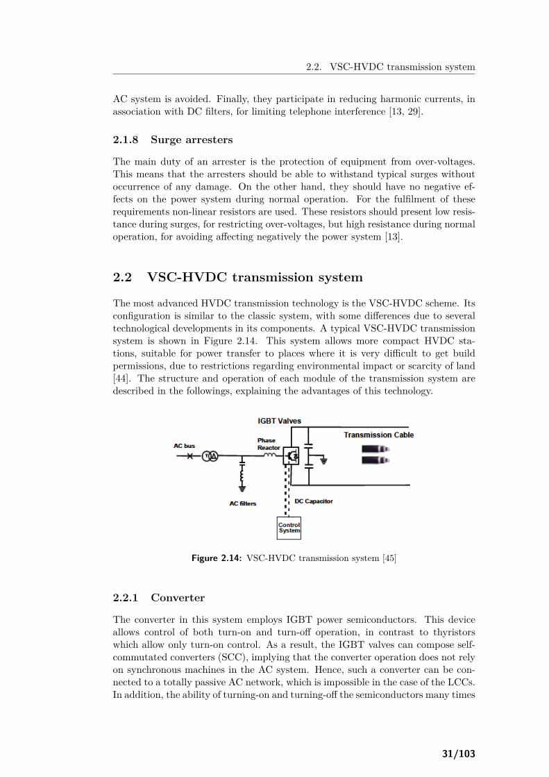
2.2. VSC-HVDC transmission system
AC system is avoided. Finally, they participate in reducing harmonic currents, inassociation with DC filters, for limiting telephone interference [13, 29].
2.1.8 Surge arresters
The main duty of an arrester is the protection of equipment from over-voltages.This means that the arresters should be able to withstand typical surges withoutoccurrence of any damage. On the other hand, they should have no negative ef-fects on the power system during normal operation. For the fulfilment of theserequirements non-linear resistors are used. These resistors should present low resis-tance during surges, for restricting over-voltages, but high resistance during normaloperation, for avoiding affecting negatively the power system [13].
2.2 VSC-HVDC transmission system
The most advanced HVDC transmission technology is the VSC-HVDC scheme. Itsconfiguration is similar to the classic system, with some differences due to severaltechnological developments in its components. A typical VSC-HVDC transmissionsystem is shown in Figure 2.14. This system allows more compact HVDC sta-tions, suitable for power transfer to places where it is very difficult to get buildpermissions, due to restrictions regarding environmental impact or scarcity of land[44]. The structure and operation of each module of the transmission system aredescribed in the followings, explaining the advantages of this technology.
Figure 2.14: VSC-HVDC transmission system [45]
2.2.1 Converter
The converter in this system employs IGBT power semiconductors. This deviceallows control of both turn-on and turn-off operation, in contrast to thyristorswhich allow only turn-on control. As a result, the IGBT valves can compose self-commutated converters (SCC), implying that the converter operation does not relyon synchronous machines in the AC system. Hence, such a converter can be con-nected to a totally passive AC network, which is impossible in the case of the LCCs.In addition, the ability of turning-on and turning-off the semiconductors many times
31/103

2.2. VSC-HVDC transmission system
per cycle leads to improvement of the harmonic performance of the converter. Lessharmonic distortion means that VSC-HVDC systems do not have to use necessarilythe 12-pulse configuration and they normally use the 6-pulse bridge (unless this isforced for other purposes explained in the followings). The converter enables theconversion of the three phases of the AC system to a symmetrical DC voltage,which is considered constant, with fixed polarity. This explains the denominationof converters of this type as voltage-source converters. Furthermore, the converterdoes not consume reactive power from the AC network, but instead it can controlthe reactive power exchange with the system, meaning no need for reactive powercompensation [9, 32].
Each valve consists of a number of series-connected IGBTs, determined by the DCvoltage level. Across each IGBT a gate unit and voltage divider are connected, toensure even voltage distribution between the series-connected IGBTs of the valve.The proper voltage sharing within the valve is performed not only during normalswitching conditions, but also during system disturbances.
Each valve includes redundant devices for enabling the continue of operation incase of failure of an IGBT. The faulty component should not create an open cir-cuit, since the current along the valve will continue flowing and the source voltageis very high and stiff. On the contrary, the IGBT should enter into its short-circuitcondition and remain in this situation until the operation is stopped for scheduledmaintenance. This capability is very crucial, especially for series-connected IG-BTs. Thus, a reliable mode of short-circuit failure should be determined for eachindividual IGBT and verified by long-term tests.
IBGTs are switched on and off with frequencies defined by pulse-width modula-tion (PWM) algorithms. In this way, PWM enables the creation of any desiredvoltage waveform, meaning any phase angle and magnitude of the fundamentalfrequency component. The PWM switching frequencies range typically between1-2 kHz, depending on converter’s topology, system frequency and specific applica-tion [9, 17, 32, 33]. Research continues developing new more efficient modulationmethods, for achieving reduced switching frequency and therefore reduced switch-ing losses. For this purpose, several other modulation methods have been proposed,such as space vector modulation (SVM) [46] and tolerance band modulation [47].
The currently available IGBTs present limited voltage and current handling capac-ity and therefore they can not individually follow the entire voltage and power re-quirements. Series-connected valves are arranged in either a two-level or three-levelbridge, resulting in larger converter ratings. The two-level bridge is the simplestconfiguration for a three-phase converter. As shown in Figure 2.15a, it is a 6-pulsebridge, in which the thyristors have been replaced by IGBTs with inverse-paralleldiodes and the DC smoothing reactors by DC smoothing capacitors. The outletsof each phase can be connected to the positive or negative DC terminal, generatinga discrete, two-level output voltage (+Ud/2,−Ud/2, where Ud is the DC voltage),as shown in Figure 2.15b. The output voltage can be modulated by PWM algo-rithms for mitigating harmonic distortion. For keeping the current ripple relativelylow, the switching frequency must be chosen comparatively high, resulting in highswitching losses. This configuration has been used at a wide range of power lev-els, in many applications, although it presents the highest harmonics content andhighest converter losses of all the VSC configurations, mainly due to its simplicity
32/103

2.2. VSC-HVDC transmission system
(a) Configuration [17]
(b) Voltage waveforms [48]
Figure 2.15: Two-level VSC
[4, 5, 9, 17, 33].
Another possible converter topology is the three-level converter, which has similarconfiguration as the conventional two-level device, with the addition of a clampingdiode or flying capacitor, for clamping the neutral point of the DC link. In this way,three different levels of the voltage output are possible at each phase, i.e. positiveDC voltage, zero voltage and negative DC voltage (+Ud/2, 0,−Ud/2, where Ud isthe DC voltage), as illustrated in Figure 2.16b. The resulted voltage resembles muchmore the ideal sinusoidal waveform than the output of the two-level converter. Thisimplies less harmonic distortion and therefore less filtering required. The topologyof a diode-clamped three-level converter, with four valves in one arm is illustratedin Figure 2.16a [4, 5, 17].
(a) Configuration [17]
(b) Voltage waveform [49]
Figure 2.16: Three-level VSC
For increasing the number of voltage levels and thus generating a better waveform(closer to sinusoidal), an extension of diode- or capacitor-clamped converters isnecessary. This will lead to increased number of devices and therefore increasedcomplexity. As a result, a strictly modular construction is needed, by cascadingthe same hardware, namely the same module. A typical solution is the cascadedH-bridge, which however requires an isolated DC power supply for each module[4]. Other cascaded converter topologies have been also suggested, with two-levelmodules (Figure 2.17) [50, 51] or five-level cross-connected modules combined withhalf-bridge modules [52]. The development of more advanced multi-level VSCs
33/103

2.2. VSC-HVDC transmission system
Figure 2.17: Cascaded two-level converter [51]
Figure 2.18: VSC and LCC losses in HVDC applications [33]
can lead to lower losses, like these that occur in conventional HVDC transmissionsystems, as can be concluded from Figure 2.18.
A new multi-level converter topology has been recently developed, called modularmulti-level converter (MMC). In this configuration each phase leg consists of twoarms; the total voltage of the two arms of each phase equals the DC voltage. Eacharm consists of n submodules. Each submodule includes two IGBTs, two diodesand a capacitor, comprising a two-terminal structure. This configuration has acommon DC link, but no common DC capacitor and filter. Figure 2.19a depictsthe MMC topology. The operation principle is that the switching devices of eachsubmodule either bypass the capacitor or connect it into the circuit, dependingon the state of the two switches. When T1 is on and T2 is off, the submodule isturned-on and the capacitor voltage is applied to the terminals of the structure.Current can either flow through D1 and charge the capacitor or through T1 anddischarge the capacitor; this depends upon the direction of the current flow. On thecontrary, when T1 is off and T2 is on, the submodule is turned-off and the capacitorvoltage is not applied to the terminals, remaining unchanged. The state in whichboth switches are turned-off should not be applicable in normal operation, since allsubmodules will identically follow this state and the converter will be blocked.
The per phase AC voltage of the converter can be controlled by turning on a numberof submodules in upper and lower arms of the same phase. Thus, by adjusting theratio of arm voltages in each phase, the desired sinusoidal waveform is achieved.The switching frequency applied to the devices of each submodule can be reduced,resulting in reduced switching losses; however, the effective frequency of the finalwaveform is very high due to the large number of submodules connected in series. Inthis way, the valve is able to synthesise a stepped voltage, with more-in-number but
34/103

2.2. VSC-HVDC transmission system
lower-in-size voltage steps, as shown in Figure 2.19b. This means reduced voltagegradients, leading to very low harmonic distortion and low high-frequency noise; thislow rate of voltage rise makes the system more robust. A result of low harmoniccontent of the voltage is the reduction in the number of tuned filters, which aremandatory in a two-level or three-level converter, due to the high and steep stepsof their voltage output; on the other hand, a drawback of MMC configuration is thedouble number of switches compared to the two-level converter. In addition, dueto sinus-shaped voltage, standard types of AC transformers can be applied in thetransmission system. From the perspective of the DC circuit, the DC voltage can beadjusted independently and therefore there is no need for isolated DC power supplyin each submodule, as in the case of the cascaded H-bridge. In general, MMCsystems present easy scalability, leading to high power ratings, up to 1000MW.This, in association to the high modularity of the topology, allows more flexibleand economical solutions for the transmission systems [3–5, 9, 48, 53].
(a) Configuration [5]
(b) Voltage waveform [49]
Figure 2.19: Modular multi-level VSC
35/103
2.2. VSC-HVDC transmission system
2.2.2 Transformers
The VSC is coupled to the AC bus via a power transformer. Its role is the sameas described in 2.1.2 for the LCC-HVDC systems. However, in the VSC-HVDCscheme, its design is usually simpler and more conventional, due to lower harmoniccontent of current [9, 17].
2.2.3 Phase reactors
These are standard single-phase air-cooled reactors. Their aim is to control activeand reactive power flow, by regulating currents through them. They are used alsoas AC filters, for reducing high-frequency harmonics of the AC current, caused bythe switching operation of the VSC. In addition, they reduce the inrush currentsupon energisation from the AC system [17, 32].
2.2.4 AC filters
Due to the switching process of IGBTs, AC output currents and voltages are notsinusoidal, i.e. the spectrum of their waveforms contains not only the fundamentalfrequency component f1, but also higher-order harmonics. This harmonic con-tent consists of components around the carrier frequency fc of the PWM and itsmultiples. The higher the number of IGBT commutations per second, the higherthe frequency of the lowest-order harmonics produced, meaning reduced harmoniclosses. On the other side, the higher the number of commutations per second,the higher the switching losses. Therefore, the frequency modulation ratio in thePWM process should be selected accordingly, to keep a balance between switch-ing and harmonic losses. These high-order harmonics have to be mitigated, forpreventing their emission into the AC system, since they could cause malfunctionof AC equipment or radio and telecommunication disturbances. For this purpose,passive high-pass filters are installed in the transmission system, providing the ACsystem with almost sinusoidal currents and voltages. In VSC-HVDC systems, theharmonic distortion is lower than in LCC-HVDC systems, since the harmonic spec-trum is shifted to higher frequencies; this, in association with the fact that noreactive power compensation is required, allows the smaller size and simpler typeof the filters required [9, 17, 32].
2.2.5 Transmission circuit
The transmission circuit is similar to that of the classic configuration. New tech-nologies have been developed regarding the DC cable types, since the current under-ground cables were found to be heavy, difficult to install and prone to faults; manyof them used oil, requiring oil pressure plants; even the cable joints were cumber-some, demanding heavy concrete constructions and requiring frequent maintenance.A first new type of DC cables, applied in the Cross Sound Cable project, was asolid dielectric submarine cable. Apart from the absence of oil, its main advantagewas its fast installation. In recent VSC-HVDC systems, a new kind of cable isused, with insulation from extruded polymer, which presents particular resistanceto the DC voltage. It employs aluminium conductor, which is more economic andlightweight than copper conductors. Moreover, it exhibits lower power losses and
36/103

2.2. VSC-HVDC transmission system
thus its design can be smaller in weight and diameter. Polymeric cables offer me-chanical strength, flexibility and low weight, and they are therefore preferable forinstallations in rural areas, where there is limited load-bearing capacity. Their ad-vantages led to more applications, as submarine cables or overhead cables; in thecase of submarine links, the cable can be laid in very deep waters and on roughbottoms. For instance, this type of cable is used in the Murraylink project and hasproven to be very reliable. Up until now, this cable has been installed in systemsup to 150 kV and 400MW; its next generation is going to be applied in systems of1100MW at 320 kV. A new type of cable, the mass impregnated cable, has startedbeing applied in systems of higher power capacity and at higher voltages, since itexhibits higher voltage capabilities [17, 51, 54–58].
In the recent VSC-HVDC grids, there are two options for the DC breaker: a me-chanical and an electronic type. Existing mechanical DC switches, e.g. activeresonance breakers, are capable of interrupting DC currents within several tens ofmilliseconds, around 60ms, duration which is considered to be too long to fulfilrequirements for a reliable DC grid. The electronic DC breaker is an IGBT-basedswitch and therefore is much faster. However, it is more expensive and, most im-portantly, exhibits relatively high losses, typically around 30% of the losses in VSCstation. For overcoming this drawback, a new generation of DC breakers has re-cently been proposed, known as hybrid DC breakers (Figure 2.20). In this new typeof DC switches, the main breaker preserves the capability of fast interrupting thefull-load short-circuit current, while the by-pass path carries the load during normaloperation, so that transfer power losses are reduced to negligible levels. Thus, thehybrid DC breaker is fast, efficient and reliable, as well as modular, meaning thatit is easily adapted to actual voltage and current ratings [59–62].
Figure 2.20: Hybrid DC breaker [60]
2.2.6 DC capacitors
The PWM switching process in the IGBTs of the VSC causes harmonics in thecurrent flowing the DC side. This results in a ripple in the DC voltage. Forproviding a low inductive path for the current, and therefore for reducing this DCvoltage ripple, two DC capacitor stacks of the same size are introduced to thesystem, each connected to one pole to ground. These capacitors are also used forkeeping the power balance during transients, by providing an energy storage. Thedesign of the DC capacitors is an important procedure during the development of
37/103

2.3. VSC-HVDC transmission system for grid connection of offshore wind farms
the whole transmission system. Their size depends on the required DC voltage.The main design factor is the capacitor’s time constant, which determines the timeneeded to charge the capacitor to the rated voltage. This value should be selectedto be sufficient for satisfying the voltage ripple and transient over-voltages. Onthe other hand, a relatively small time constant allows fast control of active andreactive power flow [17, 32, 63]. In addition to DC capacitors, DC filters andzero-sequence blocking reactors could also exist on the DC side of the transmissionsystem for mitigating interference on metallic telephone circuits, which could runadjacent to the DC links. The low harmonic content of currents and voltages inVSC-HVDC systems, allow these filters and reactors to be smaller and simpler thanin LCC-HVDC systems [45].
2.3 VSC-HVDC transmission systemfor grid connection of offshore wind farms
The aforementioned advantages of VSC-HVDC transmission systems, regarding thedesign and operation of their components, led to their wider application in the gridconnection of large offshore wind farms. The system configuration of such a VSC-HVDC connection is illustrated in Figure 2.21. The scheme consists of the offshorewind power plant (WPP) with its collector system, the offshore substation withthe relevant transformers and converters, the DC link and the onshore substationconnected to the AC grid [5]. In some cases, paralleling the DC links may beadvantageous. An appropriate power dispatch between the links can minimise thepower losses. In addition, the loss of one DC tie could result in lower power lossesthan in the case of independent DC links. However, this is found to be valid onlyin cases with large number of parallel links. The risk of cascaded tie losses shouldbe taken into account: given the loss of one link, the remaining ties should sharethe additional load, but this could lead to serious overload problems, which couldcause a cascading loss of all of them. This process could be extremely fast, so thatbreakers could not handle it. Power curtailments can become necessary, which isextremely expensive. The decision of paralleling the DC ties or not depends uponseveral factors, such as the wind turbine generator types and the control schemesof the HVDC converters (which affect the transient behaviour of the HVDC links),the dispatch constraints from regulation and market environments, the costs ofspace and weight for the equipment installed on the offshore platform, etc. [64]investigates all these aspects regarding the parallel DC links, concluding that newoperating principles have to be developed.
2.4 Suitability of transmission systemsfor grid connection of offshore wind farms
Bearing in mind the configuration and operation aspects analysed above for thedifferent transmission systems, a brief comparison could be performed, regardingtheir suitability for the grid connection of offshore wind farms. The three transmis-sion schemes (HVAC, LCC-HVDC, VSC-HVDC) are compared considering power
38/103

2.4. Suitability of transmission systems for grid connection of offshore wind farms
Figure 2.21: Grid connection of offshore wind farmthrough VSC-HVDC transmission system [5]
losses, current ratings of cables and converters, the size of the offshore substationand environmental issues. These technical aspects affect investment and operatingcosts. By taking into consideration this analysis, the feasibility of each transmissionscheme for the grid connection of offshore wind farms can be concluded, accordingto the wind farm capacity and its distance from the shore.
2.4.1 Power losses
As described in 1.4.2, in HVAC systems, power losses increase significantly withwind farm size and distance from the coast. If HVAC systems apply to highervoltage ratings, the power losses will increase. In addition, losses depend on thecharacteristics of the AC cable. On the contrary, HVDC schemes present only verylimited correlation with the transmission distance, as explained in 1.4.4. Powerlosses in HVDC systems depend more on the efficiency of the converter. In LCC-HVDC transmission technology, the total conversion efficiency lies in the range of97-98%, depending on the design of the converter. Higher efficiency implies, how-ever, higher investment cost of the converter. Comparatively low losses (2-3% for a500MW power transfer over 100 km, including losses in both converter stations) isthe main advantage of LCC-HVDC systems. Nevertheless, it should be taken intoaccount that this percentage does not include losses in the auxiliary devices at theoffshore station, for providing commutation to thyristor valves, as well as for re-active power compensation. VSC-HVDC systems present lower efficiency, 90-95%including both converter stations. This occurs due to higher losses per converterstation, around 2%, depending upon the switching frequency, as mentioned in 2.2.1.By reducing the switching frequency, lower switching losses in the converter can beachieved. On the other hand, high switching frequency means lower harmonic con-tent of voltages and currents and therefore less need for filters. Fewer filters meanlower losses in filters, smaller size of the station and lower investment cost. Hence,a balance between lower switching losses and less equipment should be managed[65]. Multi-level converters can contribute to this attempt, as described in 2.2.1.
39/103
2.4. Suitability of transmission systems for grid connection of offshore wind farms
As a result, converter losses depend significantly on its design.
2.4.2 Ratings of cables and converters
Up until now, the rating of AC cables is limited to 200MW per three-phase cableat voltages of 150-170 kV, with reactive power compensation at both ends of thelink and maximum transmission length of 200 km. This implies that, for the gridconnection of larger wind farms, more cables will be needed, apart from possibleadditional requirements for redundancy. For shorter distances, higher voltage rat-ings, up to 245 kV, are possible, and as a result the power ratings will increaseto 350-400MW. Even higher voltage levels, up to 400 kV, are under development;these applications will allow power transfer of up to 1200MVA over a distance of100 km. However, it should be borne in mind that higher voltage levels will re-sult in higher power losses, as well as in larger and more expensive transformersand submarine cables. Consequently, an increase in voltage ratings is often onlyacceptable if an increase in power capacity is required. In LCC-HVDC systems,converter and cable ratings are not limiting factors for maximum power transferin the current offshore wind farm projects (< 1000MW). On the contrary, thepresent technologies of cables in VSC-HVDC systems can transfer only 600MWat voltage level of 150 kV. In addition, only converter stations of maximum rat-ing of 300-350MW are in operation; converter stations of higher capacity, up to500MW, have been announced to become available. This means that more thanone converter stations should be constructed for utilising the full capacity of thecurrent cables. For even higher power transfer of more than 600MW more cableswill be needed. It should be also taken into consideration that links in VSC-HVDCsystems are not usually connected to ground, meaning that two conductors arealways needed, instead of one single cable in the case of LCC-HVDC systems. Ingeneral, for the grid connection of large offshore wind farms, the smallest numberof cables is required when LCC-HVDC systems are applied and the largest numberof cables is needed in the case of HVAC systems. The number of cables affectstotal investment costs. Nevertheless, the overall system reliability might increase,if more cables are used. To maximise reliability benefits, different cables shouldfollow different routes; however, this might be not always feasible [65].
2.4.3 Size of the offshore substation
HVAC systems require reactive power compensation, as explained in 1.4.2. As aresult, reactive power suppliers should be placed at both ends of the cable. Thisleads to larger offshore substations. Moreover, the application of higher voltageratings results also in larger substation, due to larger transformers that required.However, the size of an AC offshore substation is much smaller than that in theHVDC schemes, around one third of their size, mainly due to the significant spacewhich is required by the converter station. Converter stations in LCC-HVDC sys-tems need considerably more space than in VSC-HVDC systems, due to auxiliarydevices required for the commutation of the converter valves. This equipment isusually comprised by some diesel generators, which should be able to keep a strongAC system at the offshore converter, for enabling the commutation of LCCs evenduring periods of now or very little wind. Another possibility is the existence ofSTATCOMs, which could provide the necessary commutation voltage. In addition,
40/103

2.4. Suitability of transmission systems for grid connection of offshore wind farms
converter stations in LCC-HVDC systems include reactive power compensation de-vices, which are not needed in VSC-HVDC systems, as explained in 2.1.3 and 2.2.1.This leads to even larger size of the offshore substations. Nevertheless, when STAT-COMs are applied for providing the commutation voltage, the same device can beused for reactive power compensation, reducing the station equipment and there-fore the size of the substation. Furthermore, LCC-HVDC systems need more filtersthan VSC-HVDC systems, due to higher harmonic distortion of currents and volt-ages. In general, in offshore substations of LCC-HVDC systems, more equipment isrequired than in those of VSC-HVDC systems, leading to higher investment costs.This implies the reduced likelihood of applying LCC-HVDC transmission systemsfor the grid connection of small or medium wind farms, rated less than 300MW. Upuntil this capacity, VSC-HVDC systems will be preferred for the grid connectionof offshore wind farms. For higher capacities (larger offshore wind farms), mul-tiple VSC stations are required, resulting in larger offshore substations, since thepresent maximum capacity of a VSC is 300MVA. Therefore, for very large capacitydemands, the advantages of VSC-HVDC systems over the LCC-HVDC solutions,concerning space requirements, might be significantly reduced [65].
2.4.4 Environmental issues
Submarine cables installed for the grid connection of offshore wind farms usuallypass through environmentally sensitive areas, a fact that causes difficulties in ob-taining construction permits. Authorities prefer solutions with the lowest environ-mental impact. The effect of submarine cables on the environment depends ontwo factors, namely their magnetic field and their number. The solution with thelowest influence on the environment is the combination of the minimum number oflinks with the lower magnetic field of these cables. This combination is not alwayspossible, since AC cables have generally lower magnetic field than DC cables, butHVAC systems need usually more cables than HVDC schemes. Moreover, the re-quired diesel generators installed on the offshore platforms of LCC-HVDC systems,as well as diesel storage capacity, should also be taken into account, since they causeenvironmental concerns. In conclusion, the best transmission technology, from anenvironmental point of view, is very much case-dependent [65].
2.4.5 Feasibility of each transmission systemaccording to wind farm capacity and distance from the shore
Taking into consideration the aforementioned issues, some general conclusions canbe risen, regarding the suitability of each transmission system for the grid connec-tion of a wind farm, according to its capacity and distance from the shore. Thefeasibility of each option is determined by taking into account the total system cost,consisting of the investment and operating costs, including converter and transmis-sion losses. Investment costs depend on equipment ratings, whereas operating costschange with the distance from the connection point. A diagram presenting the mostfeasible transmission option for each level of wind farm capacity and at each dis-tance from the coast is illustrated in Figure 2.22. For short distances, less than100 km, where investment costs dominate over operating costs, HVDC systems arenot suitable due to high converter cost. However, this is valid only for small capaci-ties, up to 200MW, since for transferring larger amount of power requires more AC
41/103

2.5. HVDC system topologies
Figure 2.22: Transmission technology options according towind farm capacity and distance from the shore [65]
cables, leading to higher transmission losses and therefore higher operating costs.Thus, for capacities larger than 200MW, the HVDC system may be an economi-cally competitive solution, even for short distances. Increased transmission lossesin HVAC systems justify also the dominance of HVDC systems in longer distances.For capacities up to 600MW, in cases where HVDC systems are more suitable,the VSC configuration is preferable, mainly due to the lower platform equipment(absence of auxiliary devices) and therefore the lower investment cost. For ca-pacities larger than 600MW, the presently low ratings of VSC-HVDC technology(both of cable and converter) are obstacles for the application of this transmissionscheme. For transferring such amounts of power, more VSC stations are requiredon the offshore platform and more cables should be installed, leading to highercosts. Therefore, the LCC-HVDC concept is found to be more economically attrac-tive. Nevertheless, reliability issues may force the use of more cables, for avoidinglosing the whole amount of power in the case of one cable is lost. In this cases,VSC-HVDC systems will be the best solution. Besides, VSCs and cables of largerratings have been developed fast and are applied during the latest years. Apartfrom aspects regarding configurations and their corresponding costs, the enhancedcontrol capabilities of the VSC-HVDC technology should be taken into considera-tion. The ability of this transmission scheme to provide grid support, through e.g.active and reactive power control, voltage regulation, black-start capability, makesit even more advantageous for the grid connection of large offshore wind farms [65].
2.5 HVDC system topologies
HVDC converters, rectifier and inverter, can be connected through DC links in anumber of topologies. The main system topologies are shown in Figure 2.23 anddescribed in the followings.
42/103

2.5. HVDC system topologies
Figure 2.23: HVDC system topologies [28]
2.5.1 Monopolar HVDC systems
These systems are the simplest and least expensive for transferring moderate amountof power. In this topology, two converters are connected by a single pole link, at apositive or negative high voltage. The link can be insulated cable or line conductor.Most monopolar systems are designed for being expanded to bipolar topologies inthe future: there are two transmission conductors, but initially only one is used forthe monopolar system, whereas the other is either unused, used as electrode line orconnected in parallel with the main transmission conductor (like in the case of theBaltic Cable project) [9, 17, 28, 66].
2.5.1.1 Monopole with ground return
In this arrangement, the return current flows in the ground or sea at two earthelectrodes. The electrodes are located some kilometres from the stations and theirdesign depends on whether they are placed on land or at sea. The return current iscarried to the earth electrodes through medium- or low-voltage electrode lines. Thiscurrent is unidirectional, implying a complex design for the anode electrode, but asimple one for the cathode electrode. Monopoles with ground return are consider-ably cheap for power transmission over long distances. However, they could lead toproblems, like electrochemical corrosion of the buried metal objects, influences onwater chemistry or magnetic navigation compasses in case of unbalanced currents[9, 28, 66].
2.5.1.2 Monopole with metallic return
For eliminating these effects, a metallic return conductor can be installed betweenthe two ends of the monopolar transmission link. Since the converter terminalis connected to earth, the return conductor does not need insulation for the full
43/103

2.5. HVDC system topologies
transmission voltage, meaning that it costs less than the high-voltage conductor.The selection or not of a metallic return conductor relies upon technical, economicaland environmental factors. In cases of congested areas or areas with high earthresistivity the monopolar topologies with metallic return are suggested [9, 28, 66].
2.5.1.3 Monopole with grounded midpoint
This topology is an economic alternative to monopole with metallic return, since itdoes not use conductors at full transmission voltage. In this topology, the midpointof the converter is connected to earth, directly or via an impedance, to providea reference to the DC voltage. This means that the conductors operate at halfDC voltage, one positive and the other negative. The converter can be arrangedonly in 12-pulse configuration, so that there is never any stray earth current. Thistopology, known also as symmetrical monopole, is very common with VSCs whencables are used [9, 28, 66].
2.5.2 Back-to-back HVDC systems
In these systems, two converter stations are located at the same site, so that thelength of the transmission line or cable is kept as short as possible. Due to theshort conductor length, the DC voltage can be selected as low as possible, so that asmall valve hall, with a reduced number of series-connected thyristors, can be built.These systems are used to connect two adjacent asynchronous AC networks, evenat different nominal frequencies and/or no fixed phase relationship. It should bementioned that the power transfer is limited by the relative capacities of the ACsystems at the point of connection [9, 17, 28].
2.5.3 Bipolar HVDC systems
2.5.3.1 Bipole
This is the most common topology for modern HVDC transmission systems. Inthis arrangement, a single 12-pulse converter is used for each pole at each terminal.The two terminals are connected by two conductors as positive and negative poles.If both neutrals are grounded, the two poles can operate independently, creatingtwo independent DC circuits of half capacity. Under normal balanced conditions,the currents flowing at both poles are identical and therefore no earth currentflows. This results in reduced earth return losses and environmental effects. Duringoutages in one pole line, monopolar earth-return operation can be performed, byallowing the flow of half of the rated power, using the earth electrodes as returnpath. In this operation mode, losses could increase, if ground electrodes and linesare not designed for the extra current [9, 17, 28, 66].
2.5.3.2 Bipole with metallic return
For avoiding the aforementioned problem during outages at one pole, the oppositepole line can be used as metallic return, increasing the reliability of the system.For this purpose, pole/converter bypass switches should be installed at each endof the line, as shown in Figure 2.23, so that line segments can be switched off orparallelised. The usage of the line as metallic return requires also a metallic-return
44/103

2.5. HVDC system topologies
transfer breaker in the electrode line at one of the DC terminals, for commutatingthe current from the relatively low resistance of the earth into that of the DCconductor. This operation is effective during converter outages, but also in cases ofline insulation failures, if the remaining insulation is adequately strong to withstandthe low resistive voltage drop in the metallic return path [9, 17, 28].
2.5.3.3 Bipole with series-connected converters
As mentioned in 2.1.1, for HVDC transmission of very high power and at very highvoltages, 600 kV or 800 kV, series-connected converters can be used. This topologyallows reduction in energy unavailability in cases of individual converter outages orpartial line insulation failures. For instance, in a bipolar system with two series-connected converters per pole, only one quarter of the transmission capacity is lost,in the case of a single converter outage or of a degraded line insulation, able tosupport only half of the DC voltage. In addition, with this arrangement there isnot a need to change the operation mode to monopole with metallic return forlimiting the duration of emergency earth return [28].
2.5.4 Multi-terminal HVDC systems
In this topology, three or more HVDC converter stations are connected throughHVDC lines or cables, in series, parallel or hybrid (combination of series and parallelconnections) configurations. Parallel systems, in which all converters are connectedto the same voltage, are used in large capacity stations, whereas series systems, inwhich converter stations are connected in series in one or both poles, are usuallyapplied in lower capacity stations [9, 17].
Multi-terminal systems are difficult to be realised with the LCC-HVDC technology,since power reversal is achieved by reversing the polarity of the DC voltage, whichaffects all converters connected to the system. On the contrary, VSC-HVDC sys-tems do not present this problem, since the power direction is changed by changingthe current direction, whereas the polarity of DC voltage is fixed. Hence, severalVSC stations (multi-terminal systems) can be connected to DC buses with fixedpolarity, creating therefore DC grids, similar to AC networks [19, 67].
These VSC-HVDC grids, consisting of multi-terminal systems, are very attractivefor the integration of renewable energy sources, such as offshore wind farms, and forthe reinforcement of interconnected AC networks [19, 67]. Many projects investi-gate the potential benefits and cost-effectiveness of the multi-terminal configuration,such as [68]. The number of power systems with two or more HVDC links feedingpower to different points of the same AC network area is increasing. As a result,a greater interest in studying the performance of such DC links has been risen.There are a number of technical aspects that should be considered, regarding thestrength of the system compared to the amount of power transferred by the multi-ple DC links. Basic issues, such as voltage and power stability, frequency stability,over-voltages and harmonic instability due to resonances, commutation failure in-teraction between different converters, are analysed in several research activities[69–71]. In addition, the need of coordination of power modulation, as well as ofthe recovery control during faults, is also investigated in many studies [23, 69, 70].
45/103

2.6. HVDC grids with multi-terminal systems
2.6 HVDC grids with multi-terminal systems
One of the most important issues during the operation of the HVDC grids is thefault handling. In this section the procedure for properly handling a fault in a DCsystem is described. In addition, various topologies of multi-terminal systems forthe grid connection of offshore wind farms are given and compared regarding theirreliability during DC faults.
2.6.1 Handling of faults at the DC side of the transmission system
The HVDC system should react in faults in a way that the fault does not putthe entire system on risk. The faulty part should be switched out of the networkand, immediately after the fault clearance, the remaining healthy parts of the gridshould undertake again the system’s operation. The main components for the faulthandling are the AC and DC switches of the system, which can isolate the faultypart. Faults at the AC side of the system will not affect the DC side, apart from apossible power loss. In such cases, the fault handling may not necessarily includeactivation of the DC switches; instead, the converters themselves can handle typesof faults momentarily through their control systems. However, a fault at the DCside will affect the whole system. The first step for the fault handling is the tripof the AC breakers at the AC side of the converters. Thereafter, the relevant DCbreakers open to isolate the faulty section of the DC network. Finally, the ACbreakers are reclosed and the remaining healthy parts of the system can continueto operate. After clearing the fault, the converter stations and DC links can bereconnected and the system will be brought to its pre-fault state. In the case aninterruption can be accepted by the system operator, the DC switches can be slow;on the other hand, if only short interruption is acceptable, the DC switches shouldbe of high speed type, managing to bring the system back to operation in 0.5seconds after the fault. For immediate fault clearance, a detection system is alsorequired, so that it localises the fault and gives order for disconnecting only thefaulty parts [59].
2.6.2 VSC-HVDC multi-terminal system topologies
There are several different VSC-HVDC multi-terminal topologies for transferringpower from large offshore wind farms to the AC grid. In the followings the mainconfigurations are described and their operation under converter or DC link faultsis discussed.
2.6.2.1 Point-to-point topology (PPT)
This topology consists of multiple point-to-point links, each one connecting onewind farm to the grid, as shown in Figure 2.24a. In the case of a converter failureor a fault in a DC link, the AC breakers at the grid side of the converter open andthe faulted part is disconnected by the AC network. DC breakers are not neededand each line is rated for the power of a single substation. The turbines of thecorresponding wind farm are let to trip off and their power is lost. Hence, thistopology lacks flexibility [72].
46/103

2.6. HVDC grids with multi-terminal systems
(a) Point-to-point topology
(b) General ring topology
(c) Star topology
(d) Star with central switching ring topology
(e) Wind farms ring topology
(f) Substations ring topology
Figure 2.24: Multi-terminal topologies
47/103

2.6. HVDC grids with multi-terminal systems
2.6.2.2 General ring topology (GRT)
In this multi-terminal HVDC system, the lines connect all the nodes of the networkcomprising a ring, as illustrated in Figure 2.24b. Under normal conditions, thering operates in a closed loop, with all the circuit breakers and isolators closed.Nevertheless, the ring can operate also in an open loop, having a breaker or isolatoropened due to a fault. When a fault occurs in a DC line, the breakers at the endsof this line open, disconnecting the corresponding wind farm. However, the restof the circuit can continue operating. After the fault current reaching zero, theisolator between the faulty line and the disconnected wind farm opens, allowingthe breaker of the wind farm to close again and the wind farm to be connected tothe rest of the system. At the end, the DC grid works in an open loop circuit. Byreplacing the isolators with DC breakers, the wind farm will not be disconnectedat any moment, but the cost will be increased. Some lines should be rated for thewhole power of the system, since they transfer the power from all wind farms duringthe open-loop operation. The open-loop mode offers flexibility to the topology, atthe cost of NW F + NSS breakers, as well as lines, some of which should be of fullpower ratings (NW F is the number of the wind farms of the network and NSS isthe number of the onshore substations) [72].
2.6.2.3 Star topology (ST)
In this multi-terminal configuration (Figure 2.24c), each line from a wind farm ora substation is connected to a star node. A possible converter or DC link fault ishandled by opening the DC breaker and therefore disconnecting the correspondingline. Thus, the lines are rated according to the ratings of the connected VSC. Thetopology needs the same number of breakers and lines as the ring topology, butadditionally an offshore platform for the central node. Furthermore, its flexibility isnot as good as of the ring configuration, since a permanent fault in a line, connectinga wind farm to the central node, will cause the permanent loss of the power fromthis plant. Besides, a fault at the central node will lead the entire system to gooffline. Hence, this topology is not feasible for connecting wind farms to the grid[72].
2.6.2.4 Star with central switching ring topology (SGRT)
This topology is depicted in Figure 2.24d. It is a combination of the star and ringtopologies, forming a star configuration with a central node of ring configuration(which is placed on an offshore platform). A fault in a line is handled in a sameway as in star topology, by disconnecting the corresponding part. This implies,however, that the same problem in the case of permanent line fault occurs also inthis circuit arrangement, as in the star topology. The lines connecting each windfarm or substation to the central node should be rated according to the relevantVSC. Nevertheless, the central node lines should be rated to the total capacity ofthe entire system, as in the general ring topology. This configuration offers thecombined advantages of ring and star topologies, at the cost of the same numberof breakers and lines [72].
48/103
2.6. HVDC grids with multi-terminal systems
2.6.2.5 Wind farms ring topology (WFRT)
This topology consists of a wind farm ring, which additionally has links connectingeach wind farm to an onshore substation, as shown in Figure 2.24e. In the eventof a fault in a line, connecting a wind farm and a substation, the DC breakers willopen, disconnecting the wind farm from the substation, as well as from the windfarm ring. Therefore, the ring operates temporarily in the open-loop mode and thepower from the corresponding wind farm is lost. Once the current in the faultyline becomes zero, the isolator opens. Then, the breakers close again to connectthe wind farm to another substation. This operation requires that each line to asubstation should be rated according to the capacity of the corresponding station,whereas each line of the wind farm ring should have capacity equal to the sum ofthe capacities of the two wind farms at the line’s ends. The topology offers anexcellent flexibility, since it copes with line faults without a permanent loss of thepower of a wind farm. This feature is achieved at a cost of the same number oflines as the aforementioned topologies (NW F + NSS), but of a minimised numberof breakers (NW F ) [72].
2.6.2.6 Substations ring topology (SSRT)
In a similar way to the previous topology, a ring of the onshore substations isformed in this configuration, as illustrated in Figure 2.24f. This topology operatessimilarly to WFRT during a fault in DC link, with the difference that the converterin the wind farm is brought to isolation, instead of the converter of the onshoresubstation. This implies that, at the same cost of breakers and lines, this topologyoffers more flexibility in the main grid side, but less flexibility in the wind farmside than the WFRT. As a result it is more convenient to use the WFRT in mostapplications, as it allows the extraction of power from all wind farms [72].
2.6.2.7 Other topologies
At the cost of adding more breakers and lines, more complex configurations can beformed for higher performance. Examples of such topologies are a combination ofHVAC and HVDC links, a combination of a WFRT and a SSRT, a double GRT,a double ST with different central nodes, a combination of a GRT and ST bysuperposing one topology to the other, etc [72].
2.6.3 Comparison of topologies
Taking into consideration the discussion regarding the aforementioned topologies,a comparison according to several factors can be performed between the variousconfigurations. As far as the number of breakers is concerned, PPT does not needany DC switches, whereas GRT, ST and SGRT need the largest number, i.e. onefor each converter unit (NW F + NSS). The partial ring topologies, WFRT andSSRT, need DC breakers only for the converters of the ring, i.e. NW F and NSS
respectively [72].
Regarding the ratings of the DC links, in PPT, ST and SGRT lines can be ratedat the capacity of the converter to which they are connected. In WFRT and SSRT,the lines of offshore to onshore circuits should be rated to the capacity of a singlestation, whereas the lines of the ring circuit should be rated to the double of the
49/103
2.6. HVDC grids with multi-terminal systems
capacity of a station. The worst case, concerning this factor, is the GRT, wherelines have to be rated to the power capacity of the whole system, which makes thistopology economically unattractive. However, studies have reached the conclusionthat lines with the highest ratings have the lowest utilisation, whereas lines with thelowest ratings operate at full utilisation. This can be explained by the additionalredundancy that higher-rated lines provide. [72].
Flexibility of the system during a fault event is a crucial factor. All multi-terminalsystems are supposed to present flexibility under fault cases, meaning that theyshould allow redirection of the power flow in an event of a fault. In this sense, PPTis not considered as a multi-terminal topology, since the single wind farm is lostpermanently, when a fault occurs in its connection line. In GRT, the faulted part,line or converter, can be disconnected and isolated, and the rest of the system cancontinue operating in an open ring. In ST and SGRT, only a fault in a line canbe handled properly, by disconnection of one converter. On the contrary, a faultin the central node will lead the whole system to go offline. In WFRT, a faultin a line from offshore to onshore station will lead to disconnection of an onshoresubstation and the opened ring can be in service, for handling possible faults in thering. Similarly, in SSRT, a fault in a line from offshore to onshore circuits results inthe disconnection of a wind farm, while the open ring will remain under operation,able to handle faults in the ring [72].
Considering additional equipment or constructions, GRT, WFRT and SSRT requirefast communication devices to coordinate protections. On the other hand, ST andSGRT need an offshore platform for the central switching node or ring [72].
In general, the selection of the optimum topology for a given application depends onoperation and robustness requirements, as well as on the geographical location of thesubstations and the wind farms. An essential factor is the cost of the DC breakersand lines. Taken into account the recent cost of DC breakers, the most appropriatetopology is found to be the WFRT, since it is able to meet the required flexibilitywith the least number of breakers and without needing an offshore platform. Ifshorter line lengths are required, GRT can also be attractive, but it requires higherratings of some lines. Since distances between nodes, cable and breakers costsand availability of communication systems vary with the specific project, detailedanalysis is required for selecting the best topology for a given application [72].
50/103

Chapter 3Converter control schemes in a
VSC-HVDC transmission system
As mentioned in 2.4.5, the benefits, that the VSC-HVDC technology offers to thegrid, make it more attractive than other transmission systems for power transferover long distances, e.g. for the grid connection of large offshore wind farms. Thegrid support is the result of several capabilities that VSC-HVDC systems present,enabled by their control systems. These control schemes and the capabilities thatprovide are described in this chapter.
3.1 Converter control schemes
In a VSC, the switching process of the IGBTs is controlled by a PWM scheme.Therefore, with constant DC voltage, simultaneous adjustment of the magnitudeand the phase of the AC voltage output of the converter can be achieved. Thisimplies the capability for power control, since the active power is regulated bychanging the phase of the AC converter voltage, whereas the reactive power iscontrolled by adjusting the magnitude of the AC converter voltage. By adjustingthese two quantities of the AC converter voltage, operation in all four quadrants ispossible. This enables the operation of the converter close to unity power factor,and thus the maintenance of dynamic reactive power reserves, for voltage supportin contingencies, similar to a SVC. The independent control of the magnitude andthe phase of the AC converter voltage allows the separate active and reactive powercontrol. This means that the active power can be adjusted rapidly, without changingthe reactive power exchange of the converter with the AC network [28, 45].
The active and reactive power control loops take place at both sides of the DClink (rectifier and inverter). The active power control loop can be set to regulatethe active power flow according to the DC voltage, the frequency variation or anactive power reference value. The reactive power control loop can be set to controlthe reactive power flow according to the AC voltage or a reactive power referencevalue. However, not all control strategies can be used simultaneously. The selection
51/103

3.1. Converter control schemes
of different control functions depends on the application. For instance, in the caseof a passive load, the VSC should control frequency and AC voltage, whereas inthe case of an established AC system, the VSC should regulate AC voltage andactive power flow. Nevertheless, the DC voltage control is necessary for achievingactive power balance in the DC link. Therefore, one terminal of the DC link mustundertake the DC voltage control, while the other should be set to control theactive power or frequency. Concerning the reactive power regulation, either of thetwo control strategies can be selected independently at either terminal of the DClink, as presented in Figure 3.1 [17, 28, 45, 73].
Figure 3.1: Control strategies in VSC-HVDC transmission systems [17]
Hence, the control functions of a VSC include AC voltage control or reactive powercontrol, as well as DC voltage or active power control, as shown in Figure 3.2, inwhich a VSC control system is illustrated. The control system recognises also theconverter current limitations, as determined in the inner current control function[73]. The system is a cascaded control system, which consists of the inner loop,namely a fast vector controller for converter current control, and the relativelyslower outer loop, including the DC voltage controller, the AC voltage controller, theactive power controller, the reactive power controller and, possibly, the frequencycontroller [17].
Figure 3.2: Control system of VSC-HVDC transmission technology [45]
52/103

3.1. Converter control schemes
3.1.1 Inner current controller
The aim of the converter current controller is to take current reference values fromthe outer controllers, to apply current limits to these values, according to the PQcharacteristics of the converter, and finally to determine voltage reference valuesfor the VSC modulation unit. This control loop operates in a dq rotating referenceframe, synchronised by a PLL (phase locked loop) to the AC voltage at the pointof connection. The d-axis value of the reference current is generated by the outercontrollers of either the active power, the DC voltage or the grid frequency. Theq-axis value of the reference current comes out from the outer controllers of eitherthe AC voltage or the reactive power. Therefore, the d-axis current controls theactive power, whereas the q-axis current controls the reactive power. These currentreference values are used to determine reference values for the terminal voltage. Inthis way, the power exchange of the VSC is determined by the converter terminalvoltage with respect to reference voltage values [5].
The inner current control can be implemented by a PI-controller, as described in[17]. The gain factors of this controller should be defined according to stability re-quirements. Specifically, [17] concludes that the gain of the P-part of the controllershould not present high value, since this leads to instability.
3.1.1.1 Limitations
As it is known, converters do not present any overload capability, like synchronousgenerators. Therefore, a current limit should be introduced in the control system,for avoiding stress or damage of the converter valves, in the case of large transientcurrents due to disturbances. In addition, the voltage reference values produced bythe inner controller should be limited, so that the actual converter voltage will belimited according to the voltage capability of the converter [5, 17].
These current and voltage limits of the converter determine its PQ characteristics,i.e. its capability for active and reactive power transfer. In Figure 3.3 various PQcapability curves are illustrated. The upper flat part of each curve is determinedby the converter’s voltage limit, whereas the rest part of the curve is determined bythe converter’s current limit. In some cases, an under voltage limit is also required,so that the reactive power is restricted above -1 p.u., for allowing adequate ACvoltage to transmit the active power. The magnitude of the AC voltage at thepoint of connection affects the PQ characteristics of the converter: increase in ACvoltage magnitude results in decrease in reactive power exchange capability andin increase in active power exchange capability, as it is depicted in Figure 3.3 forvarious AC voltage magnitudes [5].
For following the current limits, the reference current, consisting of the active andreactive reference currents (d-axis and q-axis reference currents), is compared to thecurrent limit. If the limit is exceeded, both reference currents should be decreased.The decision of the way to limit both reference currents depends on the application.When the converter is connected to a strong grid, higher priority will be given to theactive reference current, for producing more active power. On the contrary, whenthe converter is connected to a weak power system or used to supply an industrialplant, high priority will be given to the reactive reference current, for keeping upthe AC voltage, and the rest of the power transfer capability is left available for
53/103

3.1. Converter control schemes
Figure 3.3: P-Q characteristics of grid-side VSC [5]
active power transmission [17].
3.1.1.2 Negative-sequence current
In case of unbalanced voltage conditions, i.e. asymmetrical voltages, a negativesequence of quantities should be taken into account for describing the operation ofthe VSC (the zero-sequence components can be assumed zero). Small imbalancesin three-phase voltages (imbalance factor un/up<5 %) are usually caused by un-balanced loads, uneven impedances in transmission lines, etc. Larger imbalances inthree-phase voltages are generally caused by asymmetrical faults, e.g. single-line-to-ground (SLGF) faults. Unbalanced voltages mean ripple in the DC voltage andactive power profiles. The peak-to-peak magnitude of the DC voltage ripple de-pends on the amplitude of the negative-sequence voltage and the capacitance of theDC link. From the converter prospective, it is important to preserve the stability ofthe system under unbalanced voltage conditions, by eliminating high peak-to-peakDC voltage oscillations. In addition, the compensation of the imbalance in thethree-phase voltages may be advantageous also for the host power system, sincein many cases the DC link is connected to a part of the grid with industrial loadssensitive to voltage and power deviations. As a result, VSC-HVDC transmissionsystems should include control schemes for regulating negative-sequence currents.In this way, the negative-sequence current can be controlled, for avoiding exceed-ing the limits and causing triggering of the over-current protection equipment andthus the trip of the DC link. Therefore, the inner current control loop is dividedinto a positive- and a negative-sequence current controller and reference values, ind-axis and q-axis, should be provided for both positive- and negative-sequence cur-rents. The reference values for the positive-sequence current are determined by theouter controllers, as described above. However, the reference currents for negativesequence cannot be generated in a similar way. One approach is to define zeroreference values for the negative-sequence currents, meaning that the three-phasecurrents are forced to remain balanced, regardless of the imbalance of the grid volt-age. With this current controller, the DC voltage presents oscillations, but lowerthan these in the case of the original controller. Therefore, it provides a perfectsolution, when there is no room for negative-sequence current control, i.e. when
54/103

3.1. Converter control schemes
the amount of the active power transferred through the VSC-HVDC system is veryclose to the rated value. Another improved approach is to produce non-negative,limited or unlimited, reference values for the negative-sequence currents. In thisway, the current is unbalanced, but its imbalance counters the voltage imbalance,for exchanging non-oscillating active power. As it can be observed in Figure 3.4,the DC voltage presents the lowest oscillations when the controller with limited,non-negative reference values is used [5, 17].
Figure 3.4: DC voltage during SLGF in VS-HVDC systems with andwithout negative-sequence current control [17]
[5] proposes two other control strategies for providing the reference values of thenegative-sequence currents. The first is the negative-sequence voltage compensa-tion scheme, which aims to produce the appropriate negative-sequence currentsfor eliminating the negative-sequence voltages. In that sense, the reference valuesof negative-sequence currents can be derived from the inner current controller, bysetting the reference values of negative-sequence voltage (output of inner currentcontroller) equal to zero. This open-loop control scheme provides simple controldesign, but restricts the level of voltage compensation, since the negative-sequencevoltage is maintained constant at zero. For improving and broadening the perfor-mance of this controller, a combination of open-loop control with feed-back control(implemented by a PI-controller) is also proposed. In the case that the connectionpoint is far away from the terminal, the feed-back control of the negative-sequencevoltage will provide better accuracy. This control strategy provides a very goodcompensation of the negative-sequence component of the AC voltage at the pointof connection. Nevertheless, this is achieved at the cost of higher negative-sequencecurrent and higher DC voltage and active power oscillations [5].
The last control strategy is performed by controlling the negative-sequence reactivecurrent, while the reference value of the negative-sequence active current is set tobe zero. The control is implemented through a proportional gain applied to thenegative-sequence voltage error e=uref
n −un. This gain depends on the capacity ofthe converter and the tolerance limits of the DC voltage oscillations. This controlscheme is suitable for compensating large voltage imbalances during asymmetricalfaults [5].
The aforementioned control schemes premise enough room for controlling appropri-ately the value of the negative-sequence current. In general, the room for negative-sequence current control can be increased under the following conditions [5]:
55/103
3.1. Converter control schemes
• The transmitted active power is lower than the rated, leaving room for negative-sequence current. For instance, this could occur when the wind farm produceslower power than the rated, due to lower available wind speed.
• The current rating of the converter is increased, giving space to negative-sequence current. This option might be not enough economic advantageous,especially for large wind farms, and therefore is open to further investigation.
• The injection of active power is reduced, to leave space for negative-sequencecurrent.
In the case of small imbalance factor, the required negative-sequence current is alsolow, so that the current capability of the converter can be sufficient to produce it.On the contrary, if the imbalance factor is high, the reduction of the active powerexport might become necessary to create room for the negative-sequence current.However, during a fault event, reference values for negative-sequence currents areassigned the lowest priority, to leave room for active and reactive power. In thecase of rated active power, the situation is similar as applying zero reference valueto negative-sequence current [5].
3.1.2 Outer controllers
The outer controllers are assumed to be slower than the inner current controller,so that the AC current is considered to be equal to its reference value, when it istaken into account in the outer control loop [5, 17].
3.1.2.1 DC voltage controller
One of the main targets of the grid-side converter of a HVDC transmission systemis to regulate the DC voltage at a pre-defined value. The main principle of the DCvoltage controller is to keep the energy balance over the capacitor of the converter.In this way, active power control is achieved, meaning that the appropriate exchangeof active power between converter and grid is ensured and the system balance ismaintained [5].
In Figure 3.5 a simple diagram of the DC voltage outer controller feeding theinner current controller is illustrated. The "*" quantities imply reference values.The reference value of the DC voltage can be determined according to the gridfrequency. The difference between the DC voltage reference value and the DCvoltage measured in the DC capacitor defines an error input to the PI-controller,which provides the d-axis of the reference current. This reference value should belimited according to converter current limits described in 3.1.1.1 and compared tothe actual active current, providing the difference as input to the PI-controller ofthe inner current control loop. Finally, the output of the PI-controller, as wellas the d-axis component of the AC voltage at the point of connection and thetotal reactance (transformer, AC filter and phase reactor), determine the d-axiscomponent of the AC output voltage at the grid-side converter terminal [1, 6].
3.1.2.2 AC voltage controller
As mentioned in 3.1.1, the reactive current reference value can be determined byan AC voltage controller. The control function can be distinguished depending onthe operation conditions. Under normal operation, a combination of a feed-forward
56/103

3.1. Converter control schemes
Figure 3.5: DC voltage and inner current controllers [6]
and a PI-controller is activated, enabling the voltage control mode. In the case of afault, the PI-controller is by-passed and only the feed-forward section is activated,enabling the LVRT mode. The feed-forward part of the controller comprises only aproportional gain and therefore the stability of the control scheme can be ensuredrelatively easily for the entire range of possible voltage dips [5]. A simpler controlsystem is proposed in [1, 6], in which the AC voltage controller is implementedonly by a PI-controller. Hence, its diagram is similar to the DC voltage controller,with the difference that the outer controller provides the q-axis component of thereference current and the inner current controller provides the q-axis component ofthe AC voltage at the converter terminal [1].
3.1.2.3 Active power controller
Instead of using a DC voltage controller to determine the d-axis of the referencecurrent, which is required by the inner current controller, an active power controllercan be implemented. A simple method for active power control is an open-loopcontroller, i.e. a reference value. For a more accurate control of the active power,a feedback loop can be implemented through a PI-controller, which regulates thedifference of the actual active power from its reference value, in order to determinethe reference value of the active current [1, 6]. This implementation is shown inFigure 3.6.
Figure 3.6: Active power and inner current controllers [6]
3.1.2.4 Reactive power controller
In a similar way as in the active power controller, a reactive power controller canbe used to determine the q-axis of the reference value of the current. The reac-tive power can be regulated by its reference value or by a PI-controller, which isillustrated in Figure 3.7 [1, 6].
57/103

3.1. Converter control schemes
Figure 3.7: Reactive power and inner current controllers [6]
3.1.2.5 Frequency controller
Another control possibility in the offshore-side converter is achieved by a frequencycontroller. [17] describes four different types of frequency controllers, which arebriefly described in the followings.
Frequency controller I controls the frequency at a fixed reference value, equal tothe nominal frequency. This frequency value is provided directly to the AC voltageof the converter. It should be mentioned that this type of frequency controller canonly be used in a system without other sources of frequency control [17].
Another fixed frequency controller is the frequency controller II, in which the newfrequency is determined by the voltage dynamics in the DC link and a gain. Thus,this controller is of proportional type.
Frequency controller III is based on the relationship between active power andfrequency in a power system. The principle is to introduce a PI-controller fortransforming a possible deviation in offshore frequency to a change in the activepower of the VSC. The changed active power of the converter is then introducedto the dynamic model of the offshore system for calculating the mismatch betweengeneration and consumption in this system. Finally, using the transfer function ofthe system the new frequency is determined, as shown in Figure 3.8. The transferfunction of the system is defined by the equivalent inertia constant Hsys, a dampingcoefficient D and an active damping term Ba for better rejection of disturbances.The inertia constant of the system includes the inertia constant of synchronousmachines, wind turbines and gear boxes, as well as the inertia constant of inductionmachines and their mechanical loads [17]. Although it is difficult to obtain anaccurate value for the inertia constant of the system, due to large changes dependingon the trip of synchronous machines of the system, [17] notes that the estimationof this value is crucial, since it can significantly affect the system behaviour. Anoverestimation of the system’s inertia constant is suggested, for keeping a greaterstability margin.
Instead of using a PI-controller, frequency controller IV proposes the introductionof a droop function, associating the frequency deviation with a change in the activepower of the converter, as depicted in Figure 3.9. This type of frequency controllercan be applied in cases when the system is able to tolerate small frequency devia-tions in steady state conditions or when there are other sources of frequency controlin the system [17].
58/103

3.1. Converter control schemes
Figure 3.8: Frequency controller III [17]
Figure 3.9: Frequency controller IV [17]
59/103

3.1. Converter control schemes
3.1.2.6 DC voltage droop controller for multi-terminal VSC-HVDCsystems
An extension of control strategies regarding active power and DC voltage can beapplied in the multi-terminal VSC-HVDC systems. In this case, one terminal reg-ulates the DC voltage, whereas each of the other terminals regulates its own powerflow. This control approach is known as master-slave control. However, the maindisadvantage is the lack of reliability during large disturbances, such as failure ordisconnection of master terminal. Under these conditions, the DC voltage regu-lation is lost and the DC grid experiences over-voltages or under-voltages. Forovertaking this obstacle, a modified version of master-slave control has been sug-gested, known as voltage margin control. Nevertheless, models of multi-terminalsystems with this control scheme become too complicated, due to the large numberof reference values that are required [74].
For achieving higher reliability of the system, while keeping the control structuresimple, another approach has been recently developed, the DC voltage droop con-trol: all the terminals participate in DC voltage control and therefore share theduty of power balancing in the DC grid, rather than trying to keep their activepower references. This implies that the system can deal with the outage of one ormore converters, by distributing the resulting power imbalance among the remain-ing stations. The power share of each terminal is determined by its droop constant.This DC voltage droop constant is defined as the percentage of change in the DCvoltage for 100% change in the power of the converter. Equal droop factors resultin equal power sharing among the converter terminals. In the case of unequal droopconstants, the converter stations with the higher values of droop will participatemore in the DC voltage control and therefore their power share will be smaller.The DC voltage droop controller is shown in Figure 3.10, with the correspondingdroop curve. In Figure 3.10, two controller systems are provided, depending on theconverter side at which the power is controlled. When the power control is desiredat the DC side of the converter, a negative sign block should be introduced, dueto the opposite sign conventions of the power measurements at the two convertersides [6, 74, 75].
The main idea of the DC voltage droop control is to use the DC voltage as auniversal indicator of DC grid loading, as the frequency is used in AC systems.In AC systems, active power-frequency droop is used in the governor control loop,for avoiding conflicts in reference values of frequency. In a similar way, in the DCgrids, the active power-DC voltage droop can be used to modify the reference valuesof the DC voltage, for avoiding conflicting DC voltage set values at the terminals[75]. For a more precise control scheme, the steady-state power deviations at theterminals should be taken into consideration during the calculation of the initialreference values (before their modification according to droop factor). One possiblesource of power deviations from the desired levels are the DC line voltage drops. Inthe majority of cases, the DC grid consists of significant line resistances and thusthe DC bus voltage at different terminals will present differences due to voltagedrops. Only in DC systems with very short DC links, the line resistances are smallenough to be assumed negligible, so that the steady-state DC voltage (referencevalue) can be considered the same at all DC buses. Power flow deviations can alsobe produced due to power losses in DC links and converters. [74] proposes the use
60/103

3.1. Converter control schemes
(a) Power measured at AC side
(b) Power measured at DC side
Figure 3.10: DC voltage droop controller [74]
of DC load flow analysis and converter loss estimation, for determining referencevalues for the converter power and the DC voltage. These values can be computedoffline by a central dispatcher and sent to each terminal of the DC grid. Thisapproach could enable better control of power flow in the DC grid. However, moreresearch is required on this field [74].
In a fixed droop scheme, the droop factor at each terminal is calculated accordingto the corresponding converter ratings. However, under particular operating con-ditions, not all the converters are equally loaded and therefore some of them mightnot be able to participate equitably in power sharing. Hence, it is desirable that theconverters participate in power sharing according not only to their ratings, but alsoto their spare capacity (headroom), i.e. the difference between the rated capacityand present loading. For dealing with this issue, [75] suggests a modification of theDC voltage droop controller. In the new control scheme, the droop factor is notfixed, but a function of the available headroom of each converter. The proposedfunction gives higher droop factors for lower available headrooms. In this way, con-verters which operate very close to their operational limit (low available headroom)will not share the burden of an outage to the extent that converters with higherspare capacity will do. This approach with the variable droop factor would be alsouseful in the future, when the multi-terminal HVDC grids enter the power mar-ket. It will allow the owners of the converter stations to share the power mismatchappropriately, so that they could use spare capacity also as ancillary service [75].
3.1.3 Comparison of converter control schemes
The typical converter control strategies for the grid connection of an offshore windfarm are the following [1]:
• active and reactive power control in the converter at the wind farm side - DCvoltage control and reactive power control in the converter at the grid side(Scheme 1)
61/103
3.2. Capabilities of VSC-HVDC transmission systems
• active power and AC voltage control in the converter at the wind farm side- DC voltage control and reactive power control in the converter at the gridside (Scheme 2)
[1] compares these two control schemes in the cases of a short-circuit groundedfault at the wind farm side or at the grid side, when DFIG or PMSG turbines areused. In all these four cases, the control Scheme 2 is found to be more suitable,causing oscillations of less strength in the profiles of active and reactive power andAC voltage at the non-fault side. Therefore, the AC voltage control, instead ofreactive power control, at the wind farm side is preferable for the grid connectionof offshore wind farms.
3.2 Capabilities of VSC-HVDC transmission systems
The aforementioned control systems of a VSC enable several capabilities of the VSC-HVDC transmission technology. The most advantageous of the provided attributesare described in this section.
3.2.1 Controllability
As it is mentioned in 3.1, due to the self-commutated properties of the IGBT valves,the converter can be controlled through PWM methods to create AC voltage withdesired magnitude, phase angle and frequency. This means that control signalsto the converter can change the AC output voltage and current to the networkalmost instantaneously. By varying the magnitude and phase of the grid-side ACvoltage, active and reactive power exchange between the converter and the grid canbe controlled. In this way, operation can take place in all four quadrants of active-reactive power plane, i.e. active power transfer in any direction can be combinedwith reactive power exchange in any direction (injection or absorption) [65, 76].
3.2.2 Active power control and frequency response capability
Converters can be controlled to transmit active power to the grid, equal to theproduced power from the wind farms, disregarding losses, by maintaining constantDC voltage. In addition, the converter provides the capability to follow the poweroutput fluctuations from wind power generation and therefore to even out, within acertain limit, short dips in power generation. This allows the support of frequencycontrol in the grid [65, 76].
Instead of just exporting to the grid the active power produced by the wind farm,the wind plant converter can also adjust the frequency of the wind farm networkand thereby send signals to turbines to modify their production. In this way, thecapability of turbines for power modulation is enhanced, allowing the adjustmentof their production according to the on-line load, as many grid codes require. Itshould be mentioned, though, that active power production can only be reduced,unless the turbines operate in advance with a reserve [76].
During temporary emergencies of very low frequency, the grid-side VSC can avoidregulating the DC voltage for power balance; instead, it can reduce the active power
62/103

3.2. Capabilities of VSC-HVDC transmission systems
injection to the grid or even start absorbing active power from the network. Thisallows considerably faster power damping control and thus faster frequency responsethan an AC-connected wind farm can achieve, since turbines cannot change theirproduction faster than 0.1 p.u./ms. In this case, the excess active power in the DClink, which is not transmitted to the grid, is dissipated in a DC chopper. Still,the active power production of the wind farm should be reduced, for reducing theduration of the DC chopper operation. However, the rate of change of power doesnot have to be high for following grid code requirements, since the latter can befulfilled by the fast frequency response of the VSC [76].
The capability of power modulation can also be applied in cases of AC and DCparallel transmission lines. The power in the DC link can be controlled to reducethe power swing of parallel AC lines in an event of system disturbance. This meansthat the power order to VSC-HVDC system varies continuously to counteract poweroscillations in the AC line, as shown in Figure 3.11. This feature eliminates therisk of system collapse and therefore it can contribute to system stabilisation [16].
Figure 3.11: Stabilisation of AC transmission with parallel DC link [16]
3.2.3 Reactive power control and voltage support capability
The control of reactive power flow between the converter and the grid can be usedfor compensating the needs of the network in reactive power. This can be achievedwithin the ratings of the converter (current ratings of switching devices), but italso depends on the DC voltage ratings, the allowed tap-changer interval of thetransformer and the AC voltage ratings. The ratings of the converter are basedon maximum current and voltage and can be determined by a P-Q diagram, asexplained in 3.1.1. This implies that reactive power capabilities of a converter aretraded off for its active power capabilities [65, 76].
The reactive power control capability of the converter is used to regulate the AC
63/103

3.2. Capabilities of VSC-HVDC transmission systems
voltage of the connected network. The converter adjusts its reactive current, so thatthe set voltage at the bus is retained. In addition, the fast switching capability ofthe converter and its intelligent control systems enable the transmission system tosustain any fault in the AC network. Even during low or no wind power production,when the converter is switched to stand-by mode for reducing no-load losses, it canbe rapidly (within milliseconds) switched back to operation during a fault, in orderto control its reactive power production and therefore contribute to voltage support.The contribution to AC voltage control can be applied at both grid and wind farmsides [65, 76, 77]. [78] analyses in details the voltage support that the VSC canprovide, regarding the grid configuration of its connection with the AC system(connection of the VSC and the AC system in series, in parallel or VSC-HVDCconnection between asynchronous systems).
[79] investigates the contribution of VSC-HVDC systems to the short-circuit currentduring a fault in the network. The influence of various factors, such as the controlmode, the fault location and type, is analysed. The fault location is found to beirrelevant to the level of the short-circuit current, whereas the fault type slightlyaffects the value of the current, namely it is smaller for an one-phase fault thanfor a three-phase fault, under same load and operation condition. Regarding thecontrol mode, it is concluded that, with AC voltage control mode, the short-circuitcurrent contribution is increased, since reactive current generation is automaticallyincreased, when the AC voltage decreases. Therefore, with this control mode, theVSC-HVDC system can improve the voltage stability, by minimising the dip ofbus voltage during faults. In contrast, with reactive power control mode, there isthe risk of voltage instability or even voltage collapse, if the AC system is weakand no protection action has been taken. This can be explained by taking intoconsideration that the current order limit is decreased with a decrease in voltage,meaning that the short-circuit current also decreases. Hence, its contribution duringfaults will be negligible [79].
3.2.4 Fast response to disturbances
Fast control of the converter’s active and reactive power improves the dynamic per-formance of the system under disturbances. Indeed, the time range of converter’sresponse to a voltage change is approximately 50 ms. With such a response speed,the VSC is able to control transients and flicker and keep the AC bus voltage con-stant. Transient phenomena are difficult to be mitigated by normal synchronousgenerators, since they regulate voltage too slow. In addition, asynchronous gener-ators affect the voltage profile during AC faults, due to synchronised flicker contri-butions. These problematic situations can be dealt with by the fast voltage controlscheme of the VSC-HVDC transmission system, enhancing the transient stabilityof the system.
Furthermore, through fast active and reactive power modulation, VSCs providealso effective damping for mitigation of electromechanical oscillations [19, 65, 77,78, 80, 81]. For achieving this, the VSC-HVDC transmission system can operate inany of the following strategies [78]:
• Modulation of active power, while keeping AC voltage as constant as possible• Modulation of active and reactive power
64/103

3.2. Capabilities of VSC-HVDC transmission systems
• Modulation of reactive power, while keeping active power constant[81] presents specific research results regarding the improvement of subsynchronoustorsional damping by VSC-HVDC systems, concluding that the choice of activepower control mode, instead of DC voltage control, is more beneficial for the damp-ing function. [78, 82] suggests the combination of active and reactive power controlmodes for even better damping characteristics, as illustrated in Figure 3.12.
Figure 3.12: Rotor oscillations during AC fault for three control strategiesin VSC-HVDC transmission system [82]
3.2.5 Decoupling AC systems
Since the converters of the VSC-HVDC transmission system decouple the grid sideand wind farm side, AC disturbances at one network will not be transferred to theother side. Indeed, despite some transients in the DC voltage at both DC terminals,the AC voltage at the wind farm side is not influenced by any disturbance in thegrid, and vice versa. In addition, voltage flicker is not also transferred from the oneside to the other. Moreover, the transients caused during wind farm’s energisationare isolated from the grid. Therefore, the power quality characteristics at bothsides are improved [76].
3.2.6 Black start capability
In a traditional scheme, small-sized diesel generators should have been reservedand installed in the wind farm system, specifically for starting the wind farm andrestoring the network after a blackout. On the contrary, in VSC-HVDC systems,active and reactive power can be controlled by the VSC. Thus, the small islandnetwork of the wind farm can have sufficient strength in voltage and frequency,independent of the system’s size. This means that the VSC-HVDC transmissionsystem can provide an AC source for the energisation of the wind farm.
In general, in the case of a blackout, the VSC can instantaneously switch over to itsown internal voltage and frequency reference (PWM-based self-commutation) and
65/103
3.3. Benefits for wind turbines
therefore operate in frequency control mode as an idling "static" generator (withoutmoving parts), able to supply and energise a "black" system, i.e. a passive islandednetwork without its own generation. VSC-HVDC systems present several advan-tages regarding black start and grid restoration after blackouts. First of all, theycan control the voltage, easily and fast, avoiding harmful voltage dips associatedwith the energisation of large machines, as well as harmful over-voltages associatedwith the self-excitation phenomenon during energisation of long HVAC lines. More-over, VSC-HVDC technology can control fast the frequency of the network, keepingit within acceptable values, without requiring the network plants to participate infrequency control. Indeed, during the black start and the restoration of the ACgrid after a blackout, generation does not have to match consumption, since theVSCs of the transmission system are able to compensate for frequency and volt-age imbalances, by injecting or absorbing active and reactive power. Furthermore,possible unsuccessful energisation of transformers can also be avoided: the largeinrush current, due to the energisation of un-loaded transformers, will not causetripping problems to the converters, since they are rated at higher power capacitythan the transformers. Finally, the voltage in lines and transformers is ramped upsmoothly, minimising the risk of high transient inrush current and high transientvoltage and harmonics. Therefore, transient voltage and current stresses at equip-ment are avoided and the restoration process speeds up. Concluding, VSC-HVDCtransmission systems are found to be an ideal stand-by facility for black start andrestoration of the AC grid [10, 76, 82–85].
3.3 Benefits for wind turbines
The aforementioned capabilities imply several benefits in the design and operationof the wind turbines. These advantages are basically caused by the decoupling ofthe wind farm from the grid. The main of these benefits are the following [7, 76]:
• Wind farm is not responsible for the grid code compliance, since this is aduty of the VSC-HVDC transmission system. This allows the wind turbinedevelopers to put more effort on cost reduction issues, on the standardisationof the wind turbine design, as well as on efficiency and reliability.
• Wind turbines with an electrical coupling between stator and grid will expe-rience less mechanical stresses, since the turbine is isolated from disturbancesin the main grid. Ride-through operation will occur less frequently and phaseimbalances will be lower. As a result, the mechanical drive trains of the tur-bine will not be subjected to torque oscillations of 100 Hz. In addition, issueslike harmonic resonance and transient over-voltages can be avoided.
• The proper connection to a weak system becomes duty of the VSC-HVDCtransmission system. Hence, simpler breakers and protection design can beimplemented in the wind farm.
• Since the VSC-HVDC transmission system presents reactive power controlcapabilities, the wind farm is not responsible of reactive power control ina wide range. Therefore, the reactive power setpoint can be adjusted tominimise losses within the wind farm. Furthermore, the grid-side VSC candeliver reactive power directly to the connected network, which enhances
66/103

3.4. Benefits for TSO
power system stability. Moreover, the reactive current contribution does notdepend on the number of turbines that are on-line. Thus, this capabilityoffers higher predictability of the reactive power offered to the system.
• The control of the frequency at the wind farm side can be achieved by thecorresponding VSC according to the wind speed. This will allow the increaseof wind farm’s efficiency.
3.4 Benefits for TSO
The higher integration of renewable energy sources brings new challenges for TSOsto maintain power quality and reliability of the power system. The main respon-sibility is to identify necessary grid reinforcements, for maintaining short-circuitcurrents to acceptable levels and avoiding grid "bottlenecks", achieving, thereby,voltage stability. Regarding these issues, VSC-HVDC transmission systems are aviable alternative for the following reasons [76]:
• First of all, the fast, continuous and wide-ranged reactive power control capa-bility of the VSC-HVDC systems enhances the voltage stability. Furthermore,the control of reactive power at both sides of the DC link makes the HVDCtransmission system to behave like a series-connected compensator, whichcould enable the connection to a weak AC network.
• The short-circuit current contribution can also be controlled to the desiredvalue within the ratings of the converter. In addition, it becomes independentof the size of the wind farm.
• Uncontrolled active power or unsuitable grid connection points can causegrid "bottlenecks" and undesirable load-flow paths. Active power control inVSC-HVDC transmission systems can contribute to avoiding these problems.Moreover, due to underground cables and the compact design of the converterstation, VSC-HVDC systems can be connected at any desirable connectionpoint, e.g. to an area with large consumption.
• The most important for the TSO is that a wind farm which is grid-connectedthrough a VSC-HVDC transmission system becomes comparable to a normalpower plant. The grid-side converter can be connected directly to a control orpower dispatch center. This direct access gives the opportunity to the TSOto dispatch active and reactive power and control emergency power and ACvoltage in a straight-forward way. Hence, time delays for the communicationbetween SCADA systems and the wind turbines are no longer a problem.
67/103

3.4. Benefits for TSO
68/103

Chapter 4LVRT methods at VSC-HVDC
grid-connected wind farms
In association with the capabilities described in Chapter 3, control systems in VSC-HVDC technology enable wind farms to fulfil LVRT requirements, as they refer ingrid codes. The control methods, that are used to achieve this, are presented inthis chapter, i.e. the way in which the converter’s control systems are triggered toprovide voltage support, for meeting LVRT requirements.
4.1 LVRT requirements in E.ON. grid code
When a wind farm is connected to a grid, it is required that it fulfils various ordersfrom the power system operators, as these are described in grid codes. Theserequirements are essential for the stability of the power system and therefore verystrict. One of the major requirements is that the wind farm should stay connectedto the grid during a fault, at least temporarily or for a specified period of time.According to E.ON. Netz grid code [3, 86], in the event of a fault, large powerplants, with capacity 100 MW or higher, must stay connected and provide voltagesupport to the power system for a period of up to 150 ms after the fault occurrence,as illustrated in Figure 4.1. The power unit must remain connected as long asthe operating point is above the limit line 2. A disconnection could be allowed ifthe operating point lies between the limit lines 1 and 2. Moreover, the power unitshould provide voltage support during grid disturbances. A reactive current shouldbe exchanged, when the voltage level lies outside the ± 10 % dead-band, at a rateof 2 p.u. per p.u. voltage change, as shown in Figure 4.2. Specifically for offshorewind farms, this dead-band is ± 5 % referring to the voltage at the offshore pointof common connection [3, 87].
69/103

4.1. LVRT requirements in E.ON. grid code
Figure 4.1: LVRT requirement of E.ON. Netz grid code [3]
Figure 4.2: E.ON. Netz requirement for reactive current exchangeduring grid disturbances [3]
70/103

4.2. Dealing with faults in the AC grid
4.2 Dealing with faults in the AC grid
When a fault occurs in the host power system, the AC voltage at the point ofcommon connection is reduced. Therefore, the grid-side converter detects a voltagedip, whose level depends on the nature of the fault and the electrical distance ofthe faulty point from the converter. The converter will then respond by injectingmore active power into the grid, for balancing the DC voltage and thus the energy.This means that, if the voltage drop is large, the converter should inject a highactive current. Nevertheless, the active power capability of the converter is limited,due to the converter current limits. Besides, the injection of reactive current takesthe highest priority over the injection of active current, for compensating to thevoltage dip. This further reduces the active power exchange capability. As theactive power which is transferred from the grid-side converter to the host powersystem is reduced or limited, if the wind farm continues having the same powerproduction as in the pre-fault condition, the excess power is accumulated in thecapacitance of the HVDC transmission system and thereby the DC voltage startsrising. The rate of the rise of the DC voltage is determined by the active powerproduced by the wind farm, the power delivered to the AC system by the grid-side converter and the capacitors in the HVDC system. In order to prevent theDC voltage from reaching its upper limit, a reduction of the wind farm productionis necessary. However, the wind farm is not able to respond directly (withoutany external influence) to the changes in the grid, due to the AC/AC decouplingbetween the wind farm network and the host power system. Subsequently, if noaction is taken, the HVDC system will trip off and therefore LVRT requirementsare not met. In order to deal with this issue, additional control structures andschemes are necessary [3, 5, 88].
4.3 Control structures and methods in VSC-HVDCtransmission systems for LVRT requirements
4.3.1 DC chopper
A DC chopper is a power electronic switch device, usually an IGBT, which controlsenergy burning in a resistor. Typically, a full-power rated DC chopper is connectedin the DC link close to the grid-side converter. The DC chopper is activated whenthe rise in the DC voltage, which occurs after a fault in the grid, exceeds a thresh-old value. At this moment the DC chopper starts burning the excess energy inthe DC link, mitigating therefore the rise of the DC voltage. The frequency ofoperation during DC over-voltages should be determined by the size of the resistorand the amount of active power. For controlling the operation of the DC chopper,a hysteresis control or a PWM control method can be applied. When the faultis cleared, the grid-side converter is able to restore the active power back to thepre-fault value, which allows also the DC voltage recovery [3, 5, 88, 89].
It should be mentioned that the DC voltage does not recover instantaneously. Aslight delay occurs, caused by the recovery time of the grid-side converter controllerand mainly by the ramp rate or power gradient limit applied during the power re-covery process. Typically, the minimum permissible power ramp rate is determined
71/103

4.3. Control structures and methods in VSC-HVDC transmission systems forLVRT requirements
(a) No active power ramp applied
(b) Active power ramp applied
Figure 4.3: Active power recovery process [5]
by the grid code requirements of the host power system, for achieving short recoveryperiod. On the other hand, special concerns are risen in the case of a weak grid,since a very fast power recovery can result in an overshoot in the recovering ACvoltage and consequently in significant voltage back-swings. This can be observedin Figure 4.3, where the power recovery process is illustrated in a relatively weakgrid, with and without power ramp rate or power gradient limits applied. Withoutramp rate limits, the fast recovery causes voltage overshoot and significant back-swing, as shown in the zoomed parts of Figure 4.3. Generally, the voltage presentsmore swings as the strength of the grid decreases, which might trigger consecutiveFRTs. However, a slower power recovery period implies the utilisation of the DCchopper for a longer time period, as depicted in Figure 4.3 [5].
The major advantage of this LVRT method is that the DC chopper can be imple-mented to any HVDC system connecting an offshore wind farm, irrespectively of thetype of turbines used. Moreover, the power production of the wind farm is totallyuninterrupted during any disturbance at the grid side. Hence, mechanical stressesin the turbines are also significantly reduced. Furthermore, in a case of unbalancedfault, during the time period when the DC chopper is activated, the control ofnegative-sequence currents is not necessary, for eliminating the DC voltage ripple,since the DC voltage oscillations are suppressed by the chopper. Therefore, moreroom is left for active and reactive power, for voltage support and fault handling.In addition, the usage of DC chopper can be advantageous in cases when a fastpower regulation is required at the grid side. In a short period of time, the activepower transferred to the grid can be reduced or even its direction can be reversed,by burning the power excess in the resistor of the DC chopper. In this way, a veryfast power damping is achieved [5].
Nevertheless, the DC chopper solution presents also some major disadvantages: the
72/103
4.3. Control structures and methods in VSC-HVDC transmission systems forLVRT requirements
additional cost of the chopper components and the amount of heat that should beremoved during the fault. The heat removing capacity of the resistor is determinedby its surface area. This means that the higher the power to be dissipated, thebigger the required surface area. Thus, in many cases, an enormous physical sizeof the resistor is required, which is practically impossible [5].
4.3.2 Use of fast data communication
If a DC chopper is not desired, lowering the power production of the wind farmis the other possible solution to achieve LVRT. Since the host power system andthe wind farm network are AC/AC decoupled, information about conditions at thegrid should be transferred to the wind farm side through data signals. Usually, theinformation is in the form of active power reference, directly delivered to the controlsystem of each individual turbine. The new power reference should be written overthe reference value generated locally by the controller of the turbine. Alternatively,the voltage magnitude at the grid side can be communicated to the converter atthe wind farm side. In this way, the voltage conditions at the grid side are directlymirrored at the wind farm side. This means that the wind turbines must be ableto detect and mitigate the voltage dip by themselves, which implies that turbinesare required to have LVRT capabilities [3, 5, 89].
The speed of responding to the fault is determined by the time which the grid-side control system needs for measuring data and calculating the reference signalplus the time for the transmission of the signal over the DC cable plus the timerequired by the control system at the wind farm side for the execution of thecommand. As a result of this time delay, a peak transient DC voltage occurs. Whenthe communication time delay increases, the DC over-voltage also increases. It isessential to ensure that this time period is less than the time the DC voltage needsto rise above the maximum allowable limit at rated active power transmission.The time duration of the process is related to the energy that can be stored inthe DC link, and thus to the DC capacitance of the DC cable. By increasingthe DC capacitance, more energy can be stored and therefore the reaction timeof the system can be effectively decreased. However, even a large increase in DCcapacitance gives only a very small decrease in reaction time. This implies that sucha solution, although simple, is not reliable in long HVDC transmission systems, likethese used for the grid connection of offshore wind farms. Besides, the increase ofthe DC capacitance is not practical in applications of high power and voltage [3, 5].
4.3.3 Frequency control at the wind farm network
During steady-state operation, the offshore control system regulates frequency andvoltage to reference values, set by the control system of the wind farm, in orderto optimise the wind power production. Nevertheless, during faults, the controlsystem of the offshore converter can be assigned to regulate the frequency, whichis determined as function of the DC voltage, while still keeping a constant nominalAC voltage magnitude. Thus, as DC voltage rises, the wind turbines detect a fastincrease in frequency and ramp down their power reference, by control means similarto the droop factor of conventional plants. This implies that the time for achievingthe decrease in power output depends on the time that PLL in turbines needs to
73/103

4.3. Control structures and methods in VSC-HVDC transmission systems forLVRT requirements
detect the frequency rise and the time that the turbine controllers need for reducingthe power production. The turbines are assumed to be equipped with fully-ratedconverters and therefore capable for fast power reduction. This method causeslarge and persistent DC over-voltages, since there is no means to evacuate powerand therefore to decrease the DC voltage, unless the grid is restored. When the faultis cleared and the DC voltage is recovered, the frequency control is restored to itsoperation under normal conditions, as described above. Therefore, the productionof turbines is again optimised. However, the recovery of the power production atthe wind farm is found to be slow [3, 5, 89].
4.3.4 Other methods for reducing the active power output of theturbines in the wind farm
Instead of detecting the increase in the frequency of the wind farm network, deter-mined as function of the increase in the DC voltage, another technique for forcingthe turbines to decrease their production, is to apply to the turbine converter adroop controller, acting on the DC voltage. Below a certain threshold of the DCvoltage, a droop gain is 1; above this upper limit, the droop factor decreases lin-early to zero. The droop gain is then multiplied by the torque demand, determinedby the maximum power extraction curve of the turbine, as shown in Figure 4.4.In this way, the generator torque is rapidly reduced, which results in an increaseof the rotor speed; however, this is not a major concern, owing to the turbine ca-pability for variable-speed operation. Instead of the generator torque, the gain ofthe de-loading droop controller can be multiplied to the output of the active powercontroller of the offshore HVDC converter. Thus, for a DC voltage value higherthan the threshold, the output of the power controller is multiplied with a valuelower than 1, leading to reducing the active power. A third technique to achievethe decrease in power output of the turbines is to send a signal of power reference,which is temporarily written over the system’s power order, as described in 4.3.2.In this case, the frequency and voltage of the wind farm network remains at itsnominal value [5, 10, 88].
Figure 4.4: De-loading droop control applied in generator torque [88]
4.3.5 DC voltage control switch-over between convertersat the two sides of the transmission system
When a fault occurs at the grid side of the system, the grid-side converter is nolonger able to control the DC voltage. Due to power imbalance in the DC link,
74/103

4.3. Control structures and methods in VSC-HVDC transmission systems forLVRT requirements
the DC voltage will increase. If this increase in the DC voltage is recorded at bothsides of the transmission system, a switch-over of the DC voltage control can beapplied between the two converters. The grid-side converter relinquishes the DCvoltage control and its role is to limit the current. On the other hand, the converterat the wind farm side can be set to take over the DC voltage control when the DCvoltage exceeds a pre-defined threshold. In this way, a smooth transition duringthe exchange of DC voltage control between the two converters is ensured. Thereduction of the power production of the wind farm can be achieved as describedin 4.3.3 and 4.3.4 [5, 10, 88].
When the fault is cleared, the AC voltage at the grid recovers rapidly; therefore, thereactive current export starts decreasing, allowing the increase of the active powerinjection from the onshore converter to the grid and consequently the decrease of theDC voltage. The DC voltage decrease is monitored by the converters, which switchtheir control modes back to the pre-fault situation, as soon as the DC voltage jumpsback to the rated value. The power reference signal is removed when the controlmodes change back. In the case of frequency dependence on the DC voltage, afterDC voltage recovery, the power recovery is achieved as described in 4.3.3 [5, 10, 88].
In order to undertake the DC voltage control, the offshore converter detects if theDC voltage at its side has exceeded a certain threshold value. However, the value ofDC voltage also at the grid side should be taken into consideration, to ensure thatit does not exceed any critical upper limit. If no data communication is used, theDC voltage at the grid side should be predicted by the offshore converter. Duringsteady-state operation, this is an easy process, since the DC voltage at the grid sidecan be calculated by the known cable resistance and the DC current at the windfarm side. However, this procedure cannot be applied in the case of a fault, since theDC current at the wind farm side cannot be used to predict precisely the dynamicsof the grid-side DC voltage. Hence, the predicted value of the grid-side DC voltagewill be different from its actual value. For this reason, the upper threshold limit atthe wind farm side should be chosen carefully. It should be borne in mind that, ifit is set too small, it may trigger a false FRT mode during other events, causing anunnecessary switch-over of the DC voltage control between the two converters [5].
4.3.6 AC voltage control at the wind farm network
Instead of regulating the frequency according to DC voltage, the offshore convertercan control the AC voltage regarding the DC voltage. The detection of the DCvoltage, instead of the AC voltage at the grid-side converter, implies that no com-munication signals are needed. The DC voltage rise is monitored by the offshoreconverter, which in response ramps down fast the AC voltage. The controller forachieving this procedure is illustrated in Figure 4.5. A de-loading droop gain actson the DC voltage value for determining a factor introduced into the PWM of theoffshore converter, for adjusting properly the amplitude modulation index. Hence,when the DC voltage increases due to a fault in the AC system, the de-loading droopcontroller reduces the amplitude modulation index and therefore the AC voltageat the offshore converter terminal. In this way, a fault in the offshore networkimitates the actual fault in the onshore network. This implies that an offshoreconverter with high current ratings is required. Short-circuit currents with highDC components can occur, caused by an abrupt voltage reduction, leading to high
75/103
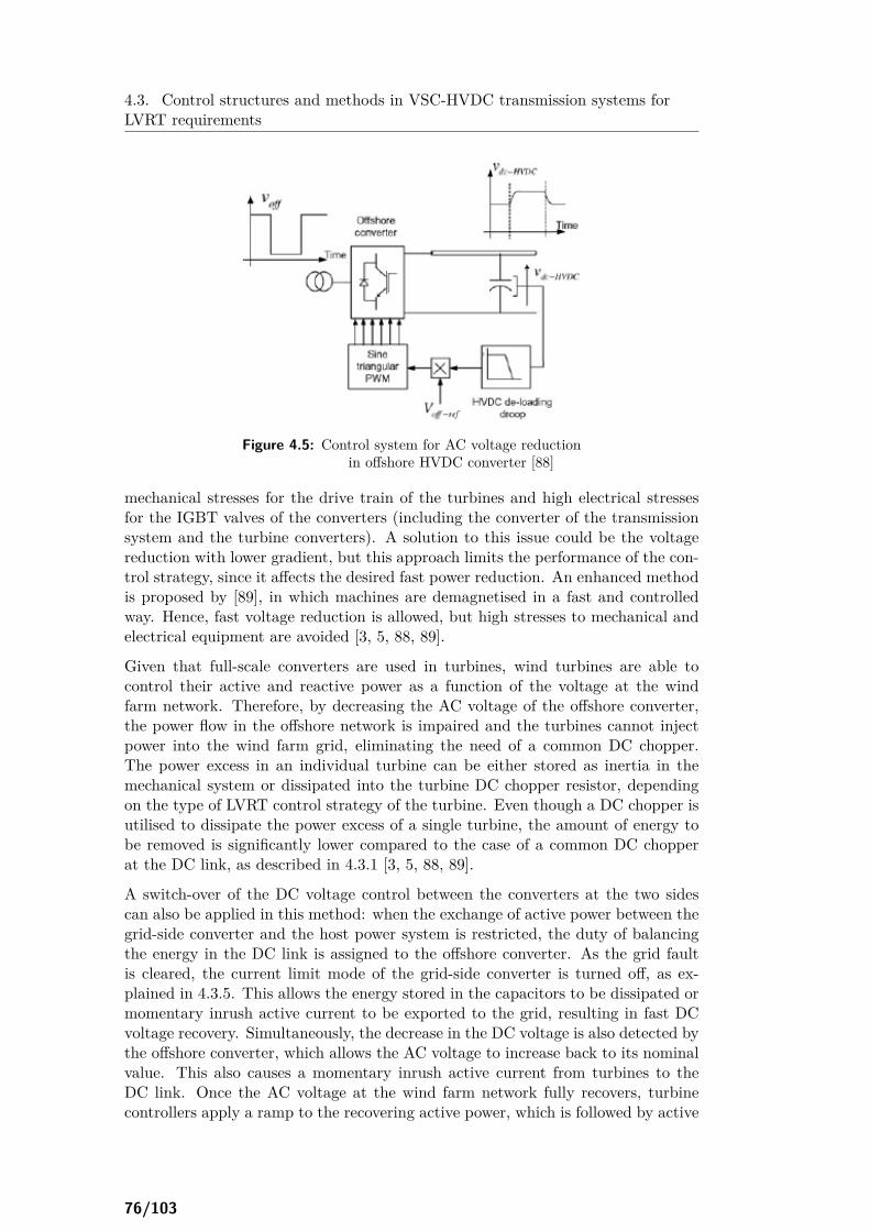
4.3. Control structures and methods in VSC-HVDC transmission systems forLVRT requirements
Figure 4.5: Control system for AC voltage reductionin offshore HVDC converter [88]
mechanical stresses for the drive train of the turbines and high electrical stressesfor the IGBT valves of the converters (including the converter of the transmissionsystem and the turbine converters). A solution to this issue could be the voltagereduction with lower gradient, but this approach limits the performance of the con-trol strategy, since it affects the desired fast power reduction. An enhanced methodis proposed by [89], in which machines are demagnetised in a fast and controlledway. Hence, fast voltage reduction is allowed, but high stresses to mechanical andelectrical equipment are avoided [3, 5, 88, 89].
Given that full-scale converters are used in turbines, wind turbines are able tocontrol their active and reactive power as a function of the voltage at the windfarm network. Therefore, by decreasing the AC voltage of the offshore converter,the power flow in the offshore network is impaired and the turbines cannot injectpower into the wind farm grid, eliminating the need of a common DC chopper.The power excess in an individual turbine can be either stored as inertia in themechanical system or dissipated into the turbine DC chopper resistor, dependingon the type of LVRT control strategy of the turbine. Even though a DC chopper isutilised to dissipate the power excess of a single turbine, the amount of energy tobe removed is significantly lower compared to the case of a common DC chopperat the DC link, as described in 4.3.1 [3, 5, 88, 89].
A switch-over of the DC voltage control between the converters at the two sidescan also be applied in this method: when the exchange of active power between thegrid-side converter and the host power system is restricted, the duty of balancingthe energy in the DC link is assigned to the offshore converter. As the grid faultis cleared, the current limit mode of the grid-side converter is turned off, as ex-plained in 4.3.5. This allows the energy stored in the capacitors to be dissipated ormomentary inrush active current to be exported to the grid, resulting in fast DCvoltage recovery. Simultaneously, the decrease in the DC voltage is also detected bythe offshore converter, which allows the AC voltage to increase back to its nominalvalue. This also causes a momentary inrush active current from turbines to theDC link. Once the AC voltage at the wind farm network fully recovers, turbinecontrollers apply a ramp to the recovering active power, which is followed by active
76/103

4.4. Dealing with faults in the wind farm network
power damping control. Therefore, the smooth exchange of DC voltage controlbetween the two converters is ensured. With this method, the DC over-voltages arelimited. In addition, the power flow to the terminal decreases rapidly and the powerrecovery after the fault clearance is faster than in the frequency control method.This occurs due to the full-scale converters of the turbines, which respond fast tothe change in the voltage, like current sources [3, 5, 88, 89].
4.3.7 Blocking of the converter
Another approach for limiting the current in the converter is the blocking of theconverter valves. The blocking process takes place for a temporary, pre-definedperiod, which is equal for all types of faults. In this way, over-currents in the con-verter are avoided. In addition, the wind turbines are allowed to remain connectedduring and after the fault, which is a grid code requirement [90].
In many fault conditions this strategy achieves a satisfactory reduction of over-currents. But in cases of more severe faults it is found to be not effective enough.In these cases, over-currents are higher and therefore longer blocking periods arerequired. If the applied blocking period is not long enough, over-currents are nottotally avoided, causing damages to cables and electronic devices of the converter,leading to turbine trip-off and power quality problems at the AC host power system.On the contrary, in the case of less severe faults, a longer blocking period thanrequired can cause additional fluctuations at the connected power system [90].
For dealing with this issue, [90] proposes a variable blocking period, as function ofthe severity of each type of fault. Moreover, a special controller is suggested, whichis activated after the de-blocking of the valves, for alleviating the oscillations at thepower system caused by the blocking process. The suggested control strategy isfound to provide optimal confrontation of faults, by totally avoiding over-currentsand the tripping of the turbines. Thus, it helps the system to reach a steady statequickly [90].
4.4 Dealing with faults in the wind farm network
In the case of offshore wind farms, where submarine cables are used, faults in thewind farm area are quite rare. However, most of the faults in a stand-alone windfarm will be difficult to clear. Following a severe fault, the system will trip off, untilmaintenance takes place [5].
Nevertheless, in most cases, faults can be localised to an individual turbine or asingle feeder connecting a group of turbines. In the case that there are more thanone park transformers, each allocated to a certain number of feeders, the faultycircuit can be isolated from the wind farm and a normal operation can be resumedafter a temporary disturbance. In this case, the offshore converter will either beblocked temporarily, and energy will not be exported from the wind farm, or itwill go into current limit operation. In the latter control method, turbines willrespond to the voltage dip and limit the active current injection. This is one of theadvantages of the AC voltage control mode at the wind farm side.
77/103

4.4. Dealing with faults in the wind farm network
However, for making the control system of the offshore converter simpler, the innercurrent controller is not usually implemented. Therefore, the offshore convertercan be over-loaded by the fault current. To prevent this issue, an indirect currentcontrol is applied. In this technique, the fault current can be limited, by limitingthe voltage at the wind farm network. When the current through the offshore con-verter exceeds a pre-defined upper threshold, the AC voltage limit is applied. TheAC voltage at the converter terminal is reduced to a level such that the currentthrough the converter is restricted within its maximum limit. There is always aminimum voltage, based on the equivalent system impedance, which ensures thatthe current does not exceed safe limits. When the fault is cleared by the corre-sponding circuit breaker, the fault current will stop and the nominal AC voltagewill be re-established. This control approach during faults in the wind farm areaimplies that there is no need to implement two different detection and control sys-tems for faults in the main grid or in the offshore network. In both cases of faultlocation, wind turbines respond to the change in the AC voltage of the wind farmnetwork [5, 10].
One important aspect is that the host power system remains unaffected, since theDC voltage is maintained to its set value by the onshore converter. Only a powerloss occurs, due to the limited or totally cut-off of the active power injection fromthe wind farm [5, 10].
In the case of a fault in the transmission cable, it is not possible usually to ride-through the disturbance and the shut-down of the transmission system is necessary.However, like disturbances in the wind farm area, such faults are very rare [5].
78/103

Chapter 5Frequency regulation
by VSC-HVDC grid-connectedwind farms
Nowadays, with the increase in wind power integration into the power system,operators set regulations for the contribution of wind farms to frequency regulation.In this chapter this capability of wind farms, which are grid-connected throughVSC-HVDC transmission systems, is analysed.
5.1 Frequency regulation by wind farms
Power plants should provide capabilities of frequency control, as specified by gridcodes. An over-frequency implies an excess of power production compared to theload demand. Therefore, power plants should reduce their production. In the caseof wind farms, this can be achieved by controlling the pitch angle and the tip speedratio. On the other hand, dealing with under-frequency conditions requires theincrease of power production. However, this is not easily applicable in the caseof wind farms. If turbines operate already under maximum power point trackingregime, they are not able to ramp up further their production. As a solution, de-rated operation has been proposed, i.e. production of less than maximum availablewind power. Hence, a margin for possible frequency support in under-frequencycases is provided. However, a de-rated operation implies undue loss of energy andrevenue in normal frequency conditions [3].
5.2 Frequency regulation requirements in the Danishgrid code
Figure 5.1 illustrates the requirement for frequency regulation derived from theDanish grid code [3, 91]. There are two frequency control curves: according to
79/103

5.3. Frequency regulation strategies in VSC-HVDCtransmission systems
Figure 5.1: Frequency control curves with and without marginfor upward regulation [3]
the first, only downward regulation is allowed, during over-frequency conditions;according to the second curve, both upward and downward frequency regulationis provided. In the case that a wind farm operates according to the first curve, itproduces the maximum available wind power under normal frequency conditionsand therefore it cannot contribute to upward regulation in under-frequency cases,but only to downward regulation when over-frequency occurs. On the contrary,if the wind farm operates according to the second frequency regulation curve, itproduces a de-rated amount of power, as given by the set-point value, under normalconditions, and thus it can participate in both upward and downward frequencyregulation [3].
5.3 Frequency regulation strategies in VSC-HVDCtransmission systems
Since the frequency of the offshore network is decoupled from the onshore gridfrequency, the contribution of the wind farm to frequency regulation can only beachieved if the onshore grid frequency is communicated to the offshore network. Inthis way, the wind farm can adjust its production according to the onshore gridfrequency. There are three control schemes for accomplishing this task, which aredescribed in the followings.
5.3.1 Use of DC voltage
The reference value of the onshore DC voltage changes in proportion to the onshoregrid frequency, i.e. if the onshore grid frequency increases, the reference value ofthe onshore DC voltage also increases. Consequently, the DC voltage value atthe offshore VSC-HVDC terminal increases too. The DC voltage at the offshoreterminal is measured and adjusted to compensate the voltage drop across the DClink. Therefore the DC voltage at the onshore terminal is estimated and then
80/103

5.4. Frequency regulation strategies in multi-terminal VSC-HVDC transmissionsystems
compared to the nominal value. The error derived from the comparison is used toadjust the frequency reference of the offshore network. In this way, if there is anincrease in the onshore grid frequency, the DC voltage rises and consequently theoffshore network frequency is raised. The turbine converters detect this frequencyincrease and decrease their generation according to the droop characteristics oftheir frequency regulation curves [3].
5.3.2 Communication of the onshore grid frequency to the offshoreHVDC converter
In this method, the onshore grid frequency is directly communicated to the off-shore converter of the VSC-HVDC transmission system. Then, the offshore HVDCconverter changes accordingly the frequency of the offshore network, which is mon-itored by the turbine converters for adjusting their production. In this way, theonshore grid frequency is directly replicated in the offshore network and, hence,change in the DC voltage is not needed [3].
5.3.3 Communication of the onshore grid frequency to the turbineconverters
In this technique, the onshore grid frequency is communicated directly to the tur-bine converters, for regulating accordingly their production. Therefore, no changein the DC voltage or the offshore network frequency are required. This is the mostsuitable method, as the only delay is caused by the communication process, with-out delays for calculations. It requires, of course, a reliable communication frameavailable, as the previous strategy [3].
5.4 Frequency regulation strategies in multi-terminalVSC-HVDC transmission systems
Appropriate control schemes should be developed in the multi-terminal VSC-HVDCtransmission systems for reducing frequency deviations in the connected AC grids.These frequency deviations can be caused by disturbances in the AC power system,e.g. by a loss of infeed power, as well as in the DC grid, e.g. by a loss of a converter[92].
In a case of a converter loss, without appropriate control systems, the entire bur-den of the change in power flow would be undertaken by the slack converter. Thesudden change in power import/export of the slack converter will lead to frequencydeviations in the AC system which is connected to this converter. The droop con-trol scheme which is described in 3.1.2.6 deals with this problem. The controlsystem is given again in Figure 5.2a. The voltage reference is modified according tothe droop coefficient βj of the jth converter and is introduced to the PI-controller,which derives the d-axis current reference Idj for the inner current controller of thecorresponding converter. Normally, squared values of half reference and measuredDC voltages are used. Since local voltage feedback leads to a non-unique powerflow solution for the multi-terminal HVDC grid, a common voltage VDcomm atany converter station is communicated as feedback signal to the control system of
81/103

5.4. Frequency regulation strategies in multi-terminal VSC-HVDC transmissionsystems
(a) Autonomous power sharing
(b) Power sharing and frequency supportof adjacent AC system
Figure 5.2: DC voltage droop control in the jth converter of multi-terminalVSC-HVDC grid [92]
the converters. With this control structure, power sharing between the remainingconverter stations is achieved and therefore none of them undertakes the entire bur-den. This reduces the change in power import/export from the converter stationsto the connected AC systems; consequently, the frequency deviation is distributedamongst different AC networks connected to different converters [92].
However, this autonomous droop control still leads to inappropriate frequency de-viations in different AC systems due to the following reasons [92]:
• In the case of a disturbance in an AC system, the frequency of that powersystem changes according to the equivalent governor droop function. Thismeans that the autonomous power sharing control system does not participatein reducing the frequency deviation, since there is no change in the net powerexchange with the concerned AC system.
• Following a converter loss, the power deviation is distributed appropriatelyamongst different converter stations. However, this power sharing might re-sult in higher frequency deviations in some AC power systems, dependingon the number of stations that are connected to each AC system and thegovernor droop coefficients of different AC grids.
• The autonomous power sharing takes place only between the converters in theaffected pole, i.e. in the pole where the lost converter was connected. Theconverters in the other pole will keep on operating at their pre-contingencyconditions and therefore do not participate in power sharing. This meansthat frequency deviation in some AC power systems could be large.
• With autonomous power sharing control, the frequency support cannot beappropriately shared among the AC grids interconnected through the multi-terminal VSC-HVDC transmission systems.
For dealing with these issues, the standard autonomous power sharing controlscheme is modified with the introduction of a frequency droop control loop. Indeed,the power reference of the converter is adjusted by a supplementary frequency droopcontrol, as illustrated in Figure 5.2b. The frequency fj of the AC power system,which is connected to the jth converter, is used as a feedback signal, to produce afrequency error, which is then multiplied by the frequency droop coefficient βf j , toregulate the power reference. Pj
∗ is considered positive for converter operation asinverter. In the case of frequency decrease (increase), the active power injected to
82/103

5.4. Frequency regulation strategies in multi-terminal VSC-HVDC transmissionsystems
the AC system should be increased (decreased), by changing the power referenceaccordingly. It should be noted that, with the modified control scheme, convertersat both poles participate in frequency support. The improved control scheme inthe multi-terminal VSC-HVDC transmission systems is found to be effective in re-ducing the frequency deviation in the connected AC systems following disturbancesat both AC and DC grids [92].
83/103

5.4. Frequency regulation strategies in multi-terminal VSC-HVDC transmissionsystems
84/103

Chapter 6Requirements for the
grid connection of wind farmsthrough HVDC systems
In chapters 4-5 grid code requirements regarding LVRT and frequency regulation forthe grid connection of power plants were provided. In this chapter more specific gridcode requirements for the integration of offshore wind farms into the power systemare given. These requirements, [93], are supplementary to the general grid coderules provided in [86]. In addition, they are enhanced by technical rules applied topower plants connected to the grid through HVDC transmission systems, as definedin [94]. The two grid codes should be combined in the case of offshore wind farmsgrid-connected through HVDC systems, so that technical restrictions of wind farmsare taken into consideration but without limiting the capabilities provided by theHVDC connection system.
6.1 Frequency range
The nominal frequency for the offshore network is 50 Hz. In contrast to the fre-quency range as specified in [86], an extended range is applicable, as shown inFigure 6.1:
• For an uninterrupted continuous operation within a limited duration of 10minutes: 47.5 − 51.5 Hz.
• For operation within a limited duration up to 10 seconds: 46.5 − 53.5 Hz.The following emergency control actions should be implemented in the wind farmsystem:
• The offshore wind farm must be disconnected from the grid, when the fre-quency at the offshore network reaches a level of less than 46.5 Hz or greaterthan 53.5 Hz and after a time delay of 300 ms.
85/103

6.1. Frequency range
Figure 6.1: Duration of operation of an offshore wind farmin different frequency ranges [93]
• The offshore wind farm must be disconnected from the grid, when the fre-quency at the offshore network reaches a level of less than 47.5 Hz or greaterthan 51.5 Hz and after a time delay of 10 s.
The aforementioned system protection functions are associated with the basic re-quirements for the duration of the wind farm’s operation, as illustrated in Figure6.1. There are no requirements until the maximum time values of the respectivefrequency regions are reached. Nevertheless, the maximum possible active power isassumed to be available for delivery.
However, for power plants connected to the grid through HVDC links, the frequencyranges and the maximum duration of operation could be defined according to Table6.1. Wider frequency ranges or longer time periods for operation can be agreedbetween the relevant TSO and the owner of the power plant, to allow the best useof the technical capabilities of DC-connected power plant for preserving or restoringthe system security. Nevertheless, the DC-connected power plant should be able forautomatic disconnection at specified frequencies, if required by the relevant TSO.In addition, the DC-connected power plant should be able to operate at rates offrequency change up to 2 Hz/s based on a measurement of frequency over a 500 mswindow value.
Table 6.1: Time periods for operation of DC-connected power plantfor different frequency ranges
Frequency range Time period for operation
47.0 − 47.5 Hz 15 minutes47.5 − 49.0 Hz 90 minutes49.0 − 51.0 Hz Unlimited51.0 − 51.5 Hz 90 minutes51.5 − 52.0 Hz 15 minutes
86/103

6.2. Active power controllability
6.2 Active power controllability
With regard to the capability for controlling the transmitted active power, theHVDC system should be able to adjust the transmitted active power in both di-rections within its maximum capacity. The relevant TSO has the right to define aminimum active power transmission capability for both directions and a maximumdelay within which the HVDC system should adjust the active power upon receiptof request from the TSO. In case of disturbance in one of the connected AC net-works, the HVDC system should be able to modify the transmitted active power inaccordance with pre-defined regulation sequences with an initial delay of maximum1 s after receiving the triggering signal; time delays greater than this should bejustified by the relevant TSO.
In addition, the relevant TSO has the right to require from the HVDC system fastactive power reversal, from the maximum capacity in one direction to the maximumcapacity in the other direction, within 2 s; responses to this request after longer timeperiod than 2 s must be justified by the TSO.
In general, the TSO has the right to require that the control functions of theHVDC system are able to take automatic remedial actions for active power controland frequency regulation, when system’s reserve capacity is exhausted or reducedunder a critical level, defined by the TSO.
6.3 Frequency sensitive mode
The HVDC system should be able to operate in frequency sensitive mode, mean-ing that it should be capable for adjustment of the active power transmission, forresponding to frequency deviations, as indicated in Figure 6.2, with frequency re-sponse dead-band of 0−500 mHz and a minimum droop s1 of 0.1 %. In a frequencystep change, the HVDC system should start adjusting its active power output afteran initial delay of 0.5 s and achieve within 30 s full activation up to the limit ofactive power range requested by the TSO.
Figure 6.2: Active power frequency response capabilityof a HVDC connection system [94]
87/103

6.4. Voltage range
6.3.1 Active power reduction during over-frequency
In a frequency range of 47.5−50.2 Hz, the wind farm should be able to unrestrictedlyfeed active power into the grid. Under the frequency of 47.5 Hz, the active powersupply may be shortened due to founded technical restrictions. Over the frequencyof 50.2 Hz, a frequency dependent active power reduction is required. The reductionof active power should be 40 % of the currently available power per Hz, as shownin Figure 6.3. A maximum rate of the speed of power variation equal to 25 % ofthe currently available power is permitted.
Figure 6.3: Basic requirement for the active power outputof an offshore wind farm regarding the frequency [93]
Moreover, a HVDC system should have the capability for power reduction whenthe frequency is above a threshold. The frequency threshold for activation of poweradjustment is laid between 50.2 − 50.5 Hz and is defined by the TSO. The droopsettings for the power reduction are also defined by the TSO, but they should beat least 0.1 % regarding the maximum transmission capacity of the HVDC system.
6.3.2 Active power increase during under-frequency
Although grid codes for wind farms do not provide specific requirements for activepower increase as response to under-frequency cases, the grid codes for power plantsconnected through DC links require the active power adjustment of the HVDCsystem in such occasions. The HVDC system should be able to increase its powertransmission when the frequency falls under a threshold. The frequency thresholdis determined by the TSO and is laid in the range of 49.5 − 49.8 Hz. The powerincrease should be achieved according to a droop factor of at least 0.1 %.
6.4 Voltage range
The nominal voltage at the grid connection point of an offshore wind farm (the endof the connection cable at the side of the wind farm) is usually specified at 155 kV,but other levels of nominal voltage are acceptable in single cases, after agreementwith the TSO.
In the case of power plants connected to the grid through HVDC systems, thevoltage ranges and the corresponding time durations of operation are given in Tables
88/103

6.5. Reactive power exchange and voltage stability
6.2 and 6.3, for nominal voltage values below 300 kV and between 300 − 400 kV,respectively. Wider voltage ranges or longer time periods for operation can beagreed between the relevant TSO and the owner of the power plant, to allow thebest use of the technical capabilities of DC-connected power plant for preserving orrestoring the system security. In addition, the TSO has the right to specify voltagevalues at the connection point, at which the HVDC system should be capable forautomatic disconnection.
Table 6.2: Time periods for operation of DC-connected power plantfor different voltage ranges (nominal voltage below 300 kV)
Synchronous area Voltage range Time period for operation
Continental Europe0.85 − 1.118 p.u. Unlimited
1.118 − 1.15 p.u. Decided by TSO(not less than 20 minutes)
Nordic 0.90 − 1.05 p.u. Unlimited1.05 − 1.10 p.u. 60 minutes
Great Britain 0.90 − 1.10 p.u. UnlimitedIreland 0.90 − 1.118 p.u. Unlimited
Baltic 0.85 − 1.12 p.u. Unlimited1.12 − 1.15 p.u. 20 minutes
Table 6.3: Time periods for operation of DC-connected power plantfor different voltage ranges (nominal voltage between 300−400 kV)
Synchronous area Voltage range Time period for operation
Continental Europe
0.85 − 1.05 p.u. Unlimited
1.05 − 1.0875 p.u. Decided by TSO(not less than 60 minutes)
1.0875 − 1.10 p.u. 60 minutes
Nordic 0.90 − 1.05 p.u. Unlimited1.05 − 1.10 p.u. 60 minutes
Great Britain 0.90 − 1.05 p.u. Unlimited1.05 − 1.10 p.u. 15 minutes
Ireland 0.90 − 1.05 p.u. Unlimited
Baltic 0.88 − 1.10 p.u. Unlimited1.10 − 1.15 p.u. 20 minutes
6.5 Reactive power exchange and voltage stability
In contrast to the voltage operating range given in [86], the allowed voltage oper-ating levels at the grid connection point of an offshore wind farm, in dependencyto the power factor (at maximum capacity), are given by Figure 6.4.
89/103

6.5. Reactive power exchange and voltage stability
Figure 6.4: Voltage operating range of an offshore wind farmaccording to power factor (with unrestricted active power) [93]
Figure 6.5: P/Q operation range of an offshore wind farmwithin the voltage range of ± 5 % UN [93]
90/103

6.5. Reactive power exchange and voltage stability
Figure 6.5 presents the minimum requirements regarding the reactive power supplycapability of the offshore wind farm. Capability for reactive power supply beyondthe range of these requirements is allowed, but is not defined or quantified in thepresent grid code requirements. The wind park is expected to set any operatingpoint inside the boundary limits within maximum 30 s. In a frequency range of47.5 − 51.5 Hz, the reactive power supply must be unrestrictedly possible. Beyondthis frequency range, the reactive power supply may be shortened, due to foundedtechnical restrictions at the wind farm. The P/Q operation range as illustratedin Figure 6.5 applies for the static operation of the respective offshore wind farm.The requirement is valid for voltage variation range of ± 5 % of the nominal voltage.The active power, reactive power and voltage values of the requirement refer to theunder-voltage side of the transformer. Beyond the aforementioned voltage variationrange, shortening of the required levels of the reactive power supply is allowed,in case of founded technical restrictions at the wind park. If the reactive powerdelivery through the wind farm can not be totally fulfilled for a power generationrange above 90 % of the nominal power, the necessity of external complementaryreactive power sources or an extension of the requirement according to Figure 6.5is to be decided in agreement with the TSO for each project specifically.
In the case of DC-connected power plants, the relevant TSO should define theboundaries of a U-Q/Pmax profile, within which the HVDC system should providereactive power at its maximum capacity. This profile should not exceed the Q/Pmaxinner envelope, lying within the limits of the outer envelope, as illustrated in Figure6.6. The dimensions of the profile, Q/Pmax range and voltage range, are determinedfor various synchronous areas in Table 6.4. If the profile is not rectangular, thevoltage range values represent the highest and lowest voltage points.
Figure 6.6: Boundaries of U-Q/Pmax profile of a HVDC systemat the connection point [94]
If the HVDC system operates at active power output below its maximum capacity,it should be able to operate in every possible operating point in the P-Q/Pmaxcapability diagram defined by the TSO for various per unit voltages at the connec-tion point. These voltage values should be within the inner envelope of the voltagerange defined in Table 6.4 and within the fixed outer envelope of Figure 6.6.
91/103

6.6. Required reactive current during grid faults
Table 6.4: Parameters of U-Q/Pmax profile of a HVDC systemat the connection point
Synchronous areaMaximum range of Maximum range of
Q/Pmax steady-state voltagein p.u.
Continental Europe 0.95 0.225Nordic 0.95 0.150Great Britain 0.95 0.100Ireland 1.08 0.218Baltic 1.0 0.220
6.6 Required reactive current during grid faults
The following characteristics of the wind farm’s operation should be applied:• The voltage support of the wind farm is to be activated when a voltage
dip/rise of over 5 % of the RMS value of the generator voltage occurs, asillustrated in Figure 6.7. The voltage support must start within 20 ms afterfault detection and the reactive current droop can be of 2 − 10 p.u..
• Within the dead-band, the wind farm should operate with constant powerfactor, constant reactive power or constant voltage, as defined in [86], inaccordance with the follow-on contract.
Figure 6.7: Voltage support through an offshore wind farmduring grid faults [93]
Regarding HVDC connection systems, the converter station should be able toachieve 90 % of the required change in reactive power output within a time pe-
92/103
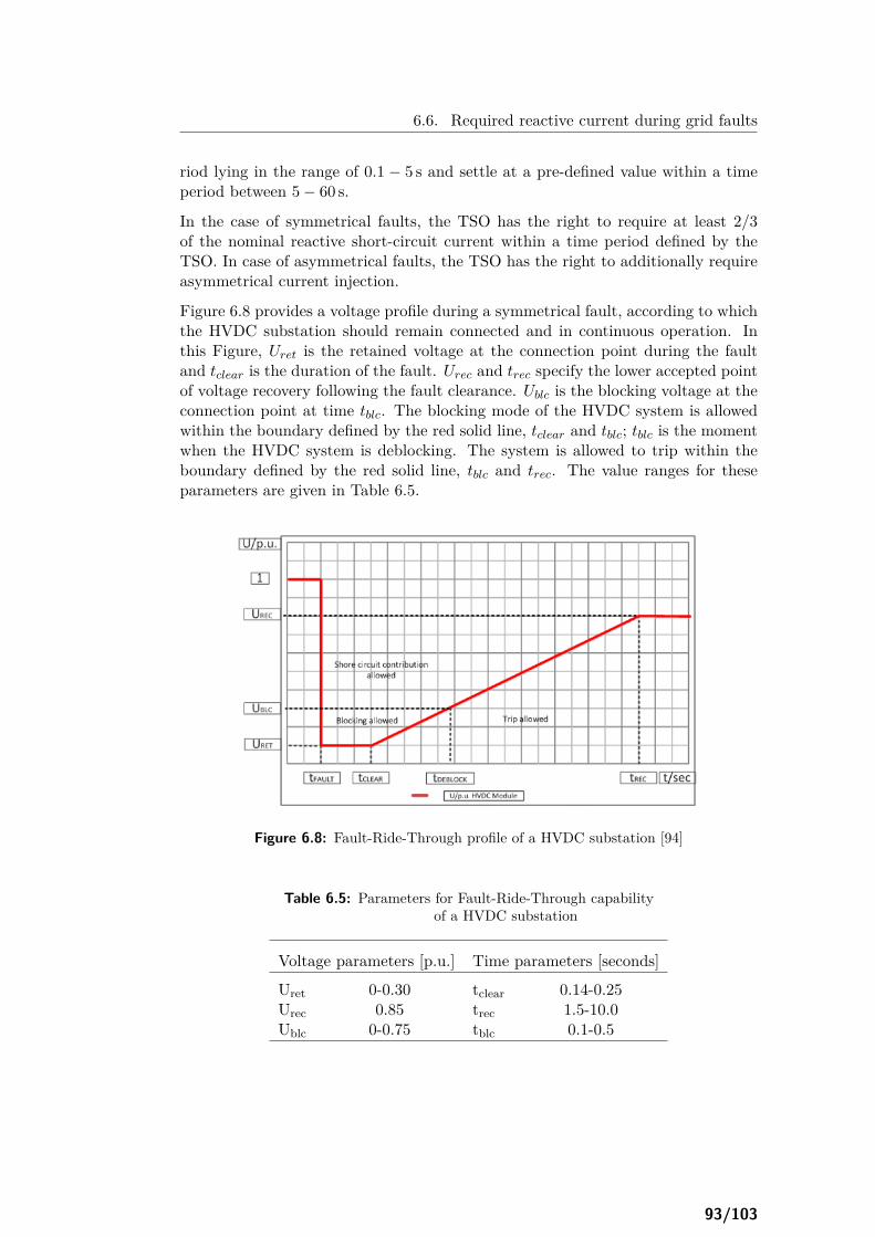
6.6. Required reactive current during grid faults
riod lying in the range of 0.1 − 5 s and settle at a pre-defined value within a timeperiod between 5 − 60 s.
In the case of symmetrical faults, the TSO has the right to require at least 2/3of the nominal reactive short-circuit current within a time period defined by theTSO. In case of asymmetrical faults, the TSO has the right to additionally requireasymmetrical current injection.
Figure 6.8 provides a voltage profile during a symmetrical fault, according to whichthe HVDC substation should remain connected and in continuous operation. Inthis Figure, Uret is the retained voltage at the connection point during the faultand tclear is the duration of the fault. Urec and trec specify the lower accepted pointof voltage recovery following the fault clearance. Ublc is the blocking voltage at theconnection point at time tblc. The blocking mode of the HVDC system is allowedwithin the boundary defined by the red solid line, tclear and tblc; tblc is the momentwhen the HVDC system is deblocking. The system is allowed to trip within theboundary defined by the red solid line, tblc and trec. The value ranges for theseparameters are given in Table 6.5.
Figure 6.8: Fault-Ride-Through profile of a HVDC substation [94]
Table 6.5: Parameters for Fault-Ride-Through capabilityof a HVDC substation
Voltage parameters [p.u.] Time parameters [seconds]
Uret 0-0.30 tclear 0.14-0.25Urec 0.85 trec 1.5-10.0Ublc 0-0.75 tblc 0.1-0.5
93/103

Bibliography
[1] D. Kong, “Advanced HVDC systems for renewable energy integration andpower transmission: modelling and control for power system transient sta-bility,” Ph.D. dissertation, University of Birmingham, School of Electronic,Electrical and Computer Engineering, June 2013.
[2] A. Agap and C. M. Dragan, “Multi-terminal DC connection for offshore windfarms,” MSc thesis, Aalborg University, Institute of Energy Technology, June2009.
[3] S. K. Chaudhary, “Control and protection of wind power plants with VSC-HVDC connection,” Ph.D. dissertation, Aalborg University, Department ofEnergy Technology, September 2011.
[4] S. Meier, “System aspects and modulation strategies of an HVDC-based con-verter system for wind farms,” Ph.D. dissertation, Royal Institute of Technol-ogy, School of Electrical Engineering, Department of Electrical Energy Con-version, 2009.
[5] R. Sharma, “Electrical structure of future off-shore wind power plant with ahigh voltage direct current power transmission,” Ph.D. dissertation, TechnicalUniversity of Denmark, Department of Electrical Engineering, October 2011.
[6] M. B. Uría, “Operation and control of multi-terminal DC (MTDC) grids,”MSc thesis, Aalborg University, June 2013.
[7] Y. Xue and V. Akhmatov, “Grid-connection of large offshore windfarms utiliz-ing VSC-HVDC: modeling and grid impact,” Wind Engineering, vol. 33, no. 5,pp. 417–432, 2009.
[8] D. G. Fink and H. W. Beaty, Standard handbook for electrical engineers,14th ed. McGraw-Hill, Inc., 1999.
[9] J. Arrillaga, High voltage direct current transmission, 2nd ed. Institution ofElectrical Engineers, 1998.
[10] L. Xu and B. R. Andersen, “Grid connection of large offshore wind farms usingHVDC,” Wind Energy, vol. 9, no. 4, pp. 371–382, 2006.
95/103

Bibliography
[11] D. M. Larruskain, I. Zamora, A. J. Mazón, O. Abarrategui, and J. Monasterio,“Transmission and distribution networks: AC versus DC,” Available online at:http://www.solarec-egypt.com.
[12] L. Weimers, “HVDC LIGHT - a new technology for a better environment,”IEEE Power Engineering Review, vol. 18, no. 8, pp. 19–20, 1998.
[13] Siemens AG, Energy Sector, Power Transmission Division, “High voltage directcurrent transmission - proven technology for power exchange,” Available onlineat: www.siemens.com/energy/hvdc.
[14] O. Heyman, L. Weimers, and M.-L. Bohl, “HVDC - a key solution in futuretransmission systems,” Available online at: www.abb.com/hvdc.
[15] O. Saksvik, “HVDC technology and smart grid,” in Proceedings of 9th IETInternational Conference on Frontier Computing, Hong Kong, 18-21 November2012.
[16] G. Flisberg, C.-G. Carlsson, R. Moni, and A. B. Boveri, “Global trends in bulkpower transmission,” Available online at: www.abb.com/hvdc.
[17] C. Du, “VSC-HVDC for industrial power systems,” Ph.D. dissertation,Chalmers University of Technology, Department of Energy and Environment,Division of Electric Power Engineering, April 2007.
[18] E. M. Callavik, P. Lundberg, M. P. Bahrman, and R. P. Rosenqvist, “HVDCtechnologies for the future onshore and offshore grid,” in Proceedings of CigréSymposium "Grid of the future", October 2012.
[19] J. Pan, R. Nuqui, K. Srivastava, T. Jonsson, P. Holmberg, and Y.-J. Hafner,“AC grid with embedded VSC-HVDC for secure and efficient power delivery,”in Proceedings of IEEE Energy 2030 Conference, Atlanda, USA, 17-18 Novem-ber 2008.
[20] M. Wyckmans, “Innovation in the market: HVDC LIGHT, the new technol-ogy,” in Proceedings of 7th International Transmission and Distribution Con-ference and Exhibition.
[21] S. Bittencourt, A. B. Boveri, K. Eriksson, and G. Biledt, “HVDC LIGHT forelectric power transmission in a deregulated market,” in Proceedings of XVEXPO-SNTPEE Conference, Foz do Iguaçu, Paraná, Brazil, October 1999.
[22] L. Carlsson, “HVDC, a "firewall" against disturbances in high-voltage grids,”Available online at: http://www.abb.com/hvdc.
[23] R. Eriksson, “Coordinated control of HVDC links in transmission systems,”Ph.D. dissertation, Royal Institute of Technology, School of Electrical Engi-neering, Department of Electric Power Systems, 2011.
[24] G. Asplund, U. Åström, and D. Wu, “Advantage of HVDC transmission at800 kV,” in Proceedings of 14th ISH, Beijing, China, 25-28 August 2005.
[25] G. Asplund, “800 kV HVDC - alternative scenarios for long distance bulk powertransmission,” in Proceedings of CESPI, Macau, China, 27th October 2008.
96/103

Bibliography
[26] J. F. Graham, A. Persson, and G. Biledt, “The integration of remote hy-droelectric plants into the Brazilian network using HVDC transmission,” inProceedings of CIGRE 2006, 2006.
[27] G. Asplund, “Sustainable energy systems with HVDC transmission,” Availableonline at: http://www.abb.com/hvdc.
[28] M. P. Bahrman and B. K. Johnson, “The ABCs of HVDC transmission tech-nology,” IEEE Power & Energy Magazine, vol. 5, no. 2, 2007.
[29] P. Kundur, Power system stability and control. McGraw-Hill, Inc., 1994.
[30] U. Åström, L. Weimers, V. Lescale, and G. Asplund, “Power transmission withHVDC at voltages above 600 kV,” Available online at: www.abb.com/hvdc.
[31] T. Jonsson, P. Holmberg, and T. Tulkiewicz, “Evaluation of classical, CCCand TCSC converter schemes for long cable projects,” in Proceedings of Epe99,Lausanne, Switzerland, September 1999.
[32] R. Grünbaum, B. Halvarsson, and A. Wilk-Wilczynski, “Facts and HVDCLIGHT for power system interconnections,” in Proceedings of Power DeliveryConference, September 1999.
[33] R. Chokhawala, B. Danielsson, and L. Ängquist, “Power semiconductors intransmission and distribution applications,” in Proceedings of 13th Interna-tional Symposium on Power Semiconductor Devices & ICs. IPSD ’01, 2001.
[34] V. F. Lescale, “Modern HVDC: state of the art and development trends,” inProceedings of POWERCON ’98, International Conference on Power SystemTechnology, 1998.
[35] ABB, “CCC - capacitor commutated converters,” Available online at:http://www.abb.com/hvdc.
[36] G. Balzer and H. Müller, “Capacitor commutated converters for high powerHVDC transmission,” in Proceedings of AC-DC Power Transmission Confer-ence, 28-30 November 2001.
[37] J. Graham, B. Jonsson, and R. S. Moni, “The Garabi 2000 MW interconnec-tion back-to-back HVDC to connect weak AC systems,” Available online at:http://www.abb.com/hvdc.
[38] N. Ottosson and L. Kjellin, “Modular back-to-back HVDC, withcapacitor commutated converters (CCC),” Available online at:http://www.abb.com/hvdc.
[39] L. Carlsson, G. Flisberg, and L. Weimers, “Recent evolution in classic HVDC,”in Proceedings of 4th International Conference on Power Transmission & Dis-tribution Technology, Changsha, PR China, 2003.
[40] A. Persson, L. Carlsson, and M. Åberg, “New technologies in HVDC converterdesign,” Available online at: http://www.abb.com/hvdc.
97/103

Bibliography
[41] M. Meisingset and A. M. Golé, “A comparison of conventional and capacitorcommutated converters based on steady-state and dynamic considerations,” inProceedings of AC-DC Power Transmission Conference, 28-30 November 2001.
[42] P. Fischer, L. Ängquist, and H. P. Nee, “A new control scheme for an HVDCtransmission link with capacitor-commutated converters having the inverteroperating with constant alternating voltage,” in Proceedings of CIGRE 2012,2012.
[43] S. Gunnarsson, L. Jiang, and A. Petersson, “Active filters in HVDC transmis-sions,” Available online at: http://www.abb.com/hvdc.
[44] G. Asplund, “HVDC using voltage source converters - a new way to buildhighly controllable and compact HVDC substations,” in Proceedings of CIGRESC 23 Symposium, Paris, France, 27 August - 2 September 2000.
[45] M. P. Bahrman, J. G. Johansson, and B. A. Nilsson, “Voltage source convertertransmission technologies - the right fit for the application,” Available onlineat: http://www.abb.com/hvdc.
[46] A. Lesnicar and R. Marquardt, “An innovative modular multilevel convertertopology suitable for a wide power range,” in Proceedings of 2003 IEEEBologna PowerTech Conference, Bologna, Italy, 23-26 June 2003.
[47] A. Hassanpoor, K. Ilves, S. Norrga, L. Ängquist, and H.-P. Nee, “Toleranceband modulation methods for modular multilevel converters,” in Proceedingsof EPE, Lille, France, 3 September 2013.
[48] M. Davies, M. Dommaschk, J. Dorn, J. Lang, D. Retzmann, and D. So-erangr, “HVDC PLUS - basics and principle of operation,” Available onlineat: www.siemens.com/energy/hvdc.
[49] E. W. Kimbark, Direct current transmission. Wiley Interscience, 1971.
[50] B. Jacobson, P. Karlsson, G. Asplund, L. Harnefors, and T. Jonsson, “VSC-HVDC transmission with cascaded two-level converters,” in Proceedings of CI-GRE 2010, 2010.
[51] N. Mahimkar, G. Persson, and C. Westerlind, “HVDC technology for largescale offshore wind connections,” in Proceedings of Smartelec, Vadodara, India,16 April 2013.
[52] A. Nami, L. Wang, F. Dijkhuizen, and A. Shukla, “Five level cross connectedcell for cascaded converters,” in Proceedings of EPE, Lille, France, 3 September2013.
[53] F. Dijkhuizen, “Multilevel converters: review, form, function and motivation,”in Proceedings of EVER 2012, Monaco, 10-13 October 2012.
[54] S. Dodds, B. Railing, K. Akman, B. Jacobson, T. Worzyk, and B. Nilsson,“HVDC VSC (HVDC LIGHT) transmission - operating experiences,” in Pro-ceedings of CIGRE 2010, 2010.
98/103

Bibliography
[55] K. Eriksson, “HVDC LIGHT and development of voltage source converters,”Available online at: http://www.abb.com/hvdc.
[56] B. Jacobson, Y. Jiang-Häfner, P. Rey, G. Asplund, M. Jeroense, A. Gustafsson,and M. Bergkvist, “HVDC with voltage source converters and extruded cablesfor up to ± 300 kV and 1000 MW,” in Proceedings of CIGRE 2006, 2006.
[57] G. Asplund, K. Eriksson, and O. Tollerz, “Land and sea cable interconnec-tions with HVDC LIGHT,” in Proceedings of CESPI 2000 Conference, Manila,Philippines, 23-27 October 2000.
[58] K. Johannesson, A. Gustafsson, J. Karlstrand, and M. Jeroense, “HVDCLIGHT cables for long distance grid connection,” in Proceedings of EuropeanOffshore Wind Conference, Stockholm, Sweden, 14-16 September 2009.
[59] E. Koldby and M. Hyttinen, “Challenges on the road to an offshore HVDCgrid,” in Proceedings of Nordic Wind Power Conference 2009, Bornholm, Den-mark, 10-11 September 2009.
[60] J. Häfner and B. Jacobson, “Proactive hybrid HVDC breakers - a key innova-tion for reliable HVDC grids,” in Proceedings of "The electric power system ofthe future - Integrating supergrids and microgrids" International Symposium,Bologna, Italy, 13-15 September 2011.
[61] M. Callavik, “HVDC grids for offshore and onshore transmission,” in Proceed-ings of EWEA Offshore Wind Conference, Amsterdam, The Netherlands, 29November - 1 December 2011.
[62] M. Callavik, A. Blomberg, J. Häfner, and B. Jacobson, “Breakthrough! ABB’shybrid HVDC breaker, an innovation breakthrough enabling reliable HVDCgrids,” Available online at: http://www.abb.com/hvdc.
[63] G. Asplund, K. Eriksson, and K. Svensson, “DC transmission based on voltagesource converters,” in Proceedings of CIGRE SC14 Colloquium, South Africa,1997.
[64] V. F. Lescale, P. Holmberg, R. Ottersten, and Y. J. Häfner, “Parallellingoffshore wind farms HVDC ties on offshore side,” in Proceedings of CIGRE2012, 2012.
[65] T. Ackermann, Wind power in power systems. John Wiley & Sons, Ltd, 2005.
[66] R. Sellick and M. Åkerberg, “Comparison of HVDC LIGHT (VSC) andHVDC CLASSIC (LCC) site aspects, for a 500MW 400kV HVDC transmissionscheme,” in Proceedings of IET ACDC 2012 conference, Birmingham, UK, 4-5December 2012.
[67] N. Hörle, K. Eriksson, A. Maeland, and T. Nestli, “Electrical supply for off-shore installations made possible by use of VSC technology,” in Proceedings ofCIGRE 2002 Conference, Paris, France, August 2002.
[68] K. M. Saxena, R. P. Bhatele, Channakeshava, A. S. R. Murty, M. Prasad,C.-G. Carlsson, and R. S. Moni, “HVDC multi-terminal interconnections - aviable and optimal solution for India,” in Proceedings of Cigre 2000 Conference,Paris, France, August/September 2000.
99/103

Bibliography
[69] P. Fischer de Toledo, G. Asplund, and E. Jansson, “Aspects on in-feed of multiple HVDC into one AC network,” Available online at:http://www.abb.com/hvdc.
[70] G. Andersson, P. Fischer de Toledo, and G. Liss, “HVDC multi-infeed perfor-mance,” Available online at: http://www.abb.com/hvdc.
[71] P. Fischer de Toledo, B. Bergdahl, and G. Asplund, “Multiple infeed short cir-cuit ratio - aspects related to multiple HVDC into one AC network,” Availableonline at: http://www.abb.com/hvdc.
[72] O. Gomis-Bellmunt, J. Liang, J. Ekanayake, R. King, and N. Jenkins, “Topolo-gies of multi-terminal HVDC-VSC transmission for large offshore wind farms,”Electric Power Systems Research, vol. 81, no. 2, pp. 271–281, 2011.
[73] J. Pan, R. Nuqui, L. Tang, and P. Holmberg, “VSC-HVDC control and appli-cation in meshed AC networks,” in Proceedings of IEEE-PES General Meeting,Pittsburg, Pennsylvania, 20-24 July 2008.
[74] T. M. Haileselassie and K. Uhlen, “Precise control of power flow in multi-terminal VSC-HVDCs using DC voltage droop control,” in Proceedings ofIEEE Power and Energy Society General Meeting, 2012.
[75] N. R. Chaudhuri and B. Chaudhuri, “Adaptive droop control for effectivepower sharing in multi-terminal DC (MTDC) grids,” IEEE Transactions onPower systems, vol. 28, no. 1, pp. 21–29, 2013.
[76] Y. Jiang-Häfner and R. Ottersten, “HVDC with voltage source converters - adesirable solution for connecting renewable energies,” in Proceedings of "Large-scale integration of wind power into power systems" Conference, Bremen, Ger-many, 14-15 October 2009.
[77] L. Zhang, L. Harnefors, and P. Rey, “Power system reliability and transfercapability improvement by VSC-HVDC (HVDC LIGHT),” in Proceedings ofCIGRE Regional Meeting in Security and Reliability of Electric Power Systems,Tallinn, Estonia, 18-20 June 2007.
[78] S. G. Johansson, G. Asplund, E. Jansson, and R. Rudervall, “Power systemstability benefits with VSC DC-transmission systems,” in Proceedings of CI-GRE Session 2004, 2004.
[79] Y. Jiang-Häfner, M. Hyttinen, and B. Pääjärvi, “On the short circuit currentcontribution of HVDC LIGHT,” Available online at: www.abb.com/hvdc.
[80] K. Eriksson, C. Liljegren, and K. Sobrink, “HVDC LIGHT experiences appli-cable for power transmission from offshore wind power parks,” Available onlineat: http://www.abb.com/hvdc.
[81] Y. Jiang-Häfner, H. Duchén, K. Lindén, M. Hyttinen, P. Fischer deToledo, T. Tulkiewicz, A.-K. Skytt, and H. Björklund, “Improvement ofsubsynchronous torsional damping using VSC HVDC,” Available online at:www.abb.com/hvdc.
100/103

[82] C. Papadopoulos, P. Papageorgiou, L. Stendius, J. Åström, M. Hyttinen, andS. Johansson, “Interconnection of Greek islands with dispersed generation viaHVDC LIGHT technology,” Available online at: http://www.abb.com/hvdc.
[83] Y. Jiang-Hafner, H. Duchen, L. Karlsson, M. Ronstrom, and B. Abrahams-son, “HVDC with voltage source converters - a powerful standby black startfacility,” in Proceedings of IEEE PES T&D Conference, Chicago, USA, 21-24April 2008.
[84] O. Vestergaard, B. Westman, G. McKay, P. Jones, J. Fitzgerald, andB. Williams, “HVDC - enabling the transition to an energy system based onrenewables,” in Proceedings of 9th IET International Conference on AC andDC Power Transmission (ACDC 2010), 2010.
[85] P. Sandeberg and L. Stendius, “Large scale offshore wind power energy evac-uation by HVDC LIGHT,” in Proceedings of EWEC 2008, Brussels, Belgium,31 March - 3 April 2008.
[86] E.ON Netz GmbH, “Grid connection regulations for high and extra high volt-age,” E.ON Netz grid code, 1 April 2006.
[87] ——, “Requirements for offshore grid connections in the E.ON Netz network,”E.ON Netz grid code, 1 April 2008.
[88] G. Ramtharan, A. Arulampalam, J. Ekanayake, F. Hughes, and N. Jenkins,“Fault ride through of fully rated converter wind turbines with AC and DCtransmission systems,” IET Renewable Power Generation, vol. 3, no. 4, pp.426–438, 2009.
[89] C. Feltes, H. Wrede, F. W. Koch, and I. Erlich, “Enhanced fault ride-throughmethod for wind farms connected to the grid through VSC-based HVDC trans-mission,” IEEE Transactions on Power Systems, vol. 24, no. 3, pp. 1537–1546,2009.
[90] T. D. Vrionis, X. I. Koutiva, N. A. Vovos, and G. B. Giannakopoulos, “Controlof an HVdc link connecting a wind farm to the grid for fault ride-throughenhancement,” IEEE Transactions on Power Systems, vol. 22, no. 4, pp. 2039–2047, 2007.
[91] Eltra/Elkraft, “Wind turbines connected to grids with voltages above 100 kV,”Regulation TF 3.2.5, 2004.
[92] N. R. Chaudhuri, R. Majumder, and B. Chaudhuri, “System frequency sup-port through multi-terminal DC (MTDC) grids,” IEEE Transactions on PowerSystems, vol. 28, no. 1, pp. 347–356, 2013.
[93] TenneT TSO GmbH, “Requirements for offshore grid connections in the gridof TenneT TSO GmbH,” TenneT TSO grid code, 5 October 2010.
[94] ENTSO-E, “ENTSO-E draft network code on HVDC connections and DC-connected power park modules,” ENTSO-E draft grid code, 2 September 2013.
101/103


www.elektro.dtu.dkDepartment of Electrical EngineeringCentre for Electric Technology (CET)Technical University of DenmarkElektrovej building 325DK-2800 Kgs. LyngbyDenmarkTel: (+45) 45 25 38 00Fax: (+45) 45 93 16 34Email: [email protected]