Embed Size (px)
Citation preview

Control of a flexible, surface-piercing hydrofoilfor high-speed, small-scale applications
The MIT Faculty has made this article openly available. Please share how this access benefits you. Your story matters.
Citation G. D. Bousquet, M. S. Triantafyllou and J. E. Slotine, "Control ofa flexible, surface-piercing hydrofoil for high-speed, small-scaleapplications," 2017 IEEE/RSJ International Conference on IntelligentRobots and Systems (IROS), Vancouver, BC, 2017, pp. 4203-4208.
As Published http://dx.doi.org/10.1109/iros.2017.8206282
Publisher IEEE
Version Author's final manuscript
Citable link https://hdl.handle.net/1721.1/123873
Terms of Use Creative Commons Attribution-Noncommercial-Share Alike
Detailed Terms http://creativecommons.org/licenses/by-nc-sa/4.0/
Control of a flexible, surface-piercing hydrofoil for high-speed,small-scale applications
Gabriel D. Bousquet, Michael S. Triantafyllou and Jean-Jacques E. Slotine
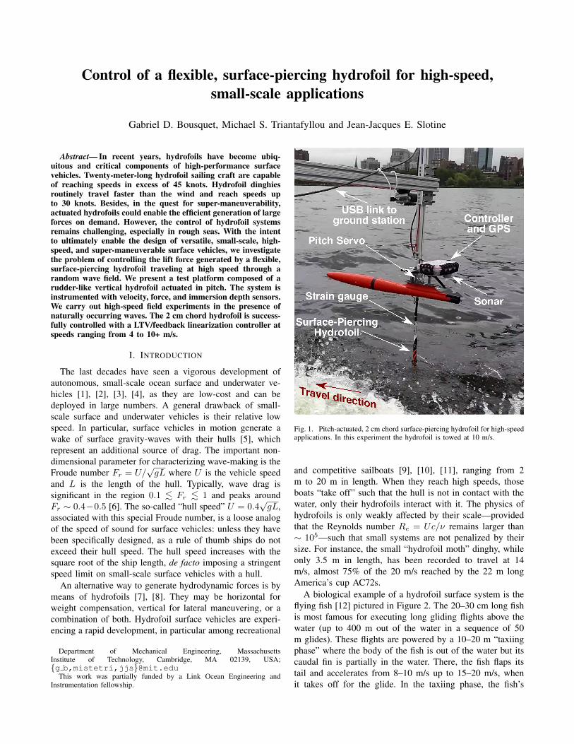
Abstract— In recent years, hydrofoils have become ubiq-uitous and critical components of high-performance surfacevehicles. Twenty-meter-long hydrofoil sailing craft are capableof reaching speeds in excess of 45 knots. Hydrofoil dinghiesroutinely travel faster than the wind and reach speeds upto 30 knots. Besides, in the quest for super-maneuverability,actuated hydrofoils could enable the efficient generation of largeforces on demand. However, the control of hydrofoil systemsremains challenging, especially in rough seas. With the intentto ultimately enable the design of versatile, small-scale, high-speed, and super-maneuverable surface vehicles, we investigatethe problem of controlling the lift force generated by a flexible,surface-piercing hydrofoil traveling at high speed through arandom wave field. We present a test platform composed of arudder-like vertical hydrofoil actuated in pitch. The system isinstrumented with velocity, force, and immersion depth sensors.We carry out high-speed field experiments in the presence ofnaturally occurring waves. The 2 cm chord hydrofoil is success-fully controlled with a LTV/feedback linearization controller atspeeds ranging from 4 to 10+ m/s.
I. INTRODUCTION
The last decades have seen a vigorous development ofautonomous, small-scale ocean surface and underwater ve-hicles [1], [2], [3], [4], as they are low-cost and can bedeployed in large numbers. A general drawback of small-scale surface and underwater vehicles is their relative lowspeed. In particular, surface vehicles in motion generate awake of surface gravity-waves with their hulls [5], whichrepresent an additional source of drag. The important non-dimensional parameter for characterizing wave-making is theFroude number Fr = U/
√gL where U is the vehicle speed
and L is the length of the hull. Typically, wave drag issignificant in the region 0.1 . Fr . 1 and peaks aroundFr ∼ 0.4−0.5 [6]. The so-called “hull speed” U = 0.4
√gL,
associated with this special Froude number, is a loose analogof the speed of sound for surface vehicles: unless they havebeen specifically designed, as a rule of thumb ships do notexceed their hull speed. The hull speed increases with thesquare root of the ship length, de facto imposing a stringentspeed limit on small-scale surface vehicles with a hull.
An alternative way to generate hydrodynamic forces is bymeans of hydrofoils [7], [8]. They may be horizontal forweight compensation, vertical for lateral maneuvering, or acombination of both. Hydrofoil surface vehicles are experi-encing a rapid development, in particular among recreational
Department of Mechanical Engineering, MassachusettsInstitute of Technology, Cambridge, MA 02139, USA;{g b,mistetri,jjs}@mit.edu
This work was partially funded by a Link Ocean Engineering andInstrumentation fellowship.
Fig. 1. Pitch-actuated, 2 cm chord surface-piercing hydrofoil for high-speedapplications. In this experiment the hydrofoil is towed at 10 m/s.
and competitive sailboats [9], [10], [11], ranging from 2m to 20 m in length. When they reach high speeds, thoseboats “take off” such that the hull is not in contact with thewater, only their hydrofoils interact with it. The physics ofhydrofoils is only weakly affected by their scale—providedthat the Reynolds number Re = Uc/ν remains larger than∼ 105—such that small systems are not penalized by theirsize. For instance, the small “hydrofoil moth” dinghy, whileonly 3.5 m in length, has been recorded to travel at 14m/s, almost 75% of the 20 m/s reached by the 22 m longAmerica’s cup AC72s.
A biological example of a hydrofoil surface system is theflying fish [12] pictured in Figure 2. The 20–30 cm long fishis most famous for executing long gliding flights above thewater (up to 400 m out of the water in a sequence of 50m glides). These flights are powered by a 10–20 m “taxiingphase” where the body of the fish is out of the water but itscaudal fin is partially in the water. There, the fish flaps itstail and accelerates from 8–10 m/s up to 15–20 m/s, whenit takes off for the glide. In the taxiing phase, the fish’s

Fr =Upgl
⇠ 0.4
Credit: Ezra Shaw
Credit: f-one
Credit: Hendrik Louw
Credit: Virginia Veal
Credit: Beneteau
Fig. 2. Comparison between hull speed and hydrofoil-based surfacevehicles across scales.
only connection to the water is the caudal fin i.e. a flapping,vertical, surface-piercing hydrofoil used for propulsion. Thismakes the flying fish in taxi phase a hydrofoil surface craft.Overall, hydrofoils appear to be features of choice for small-scale, high-speed surface vehicles, and more generally forbio-inspired and super-maneuverable ocean robots.
In general, the hydrodynamics of surface-piercing hydro-foils is a complex topic of active research [7], [8], [13],as it may concurrently involve free-surface effects (wave-making), ventilation (air from the surface is entrained intothe suction side of the hydrofoil, resulting in a sudden lossof lift and increase in drag, see [14], [13] and Figure 8), andcavitation (at high speed, water may boil in regions of lowpressure). Active control of hydrofoils has mostly focused onfully submerged systems and remains challenging, especiallyin rough seas [15].
Small-scale surface-piercing hydrofoils, designed to gen-erate lift forces O(10 N) at velocities O(10 m/s), presentunique characteristics and challenges that remain largelyunexplored. Due to their small size, even the smallest wavehas a proportionally big effect on their wetted area, leadingto fast and large amplitude forcing, and a highly time-varyingdynamics. This can be mitigated somehow by utilizing long,slender hydrofoils, but these are inherently flexible.
In this paper, we investigate the control of the lift force(more precisely, the measured torque, thereafter lumpedunder the generic term “loading”), generated by a vertical,rectangular surface-piercing hydrofoil actuated in pitch. Wederive a general model of the hydrofoil dynamics and pro-pose a linear time-varying (LTV) controller. The controlleris validated on a 2 cm chord hydrofoil, immersed by 0–20cm. The hydrofoil is sized for a design lift of 5 N at a travelspeed of 10 m/s. Tests are carried at speeds 4–10+ m/s in anoutdoor basin with naturally occurring waves.
II. EXPERIMENTAL SETUP
The experimental setup (Figure 1) was designed for a2×20 cm hydrofoil (“foil” for short) that was towed with a 40
hp whaler boat capable of speeds up to 12 m/s. Experimentswere carried on the Charles River basin near MIT, duringSummer 2016. Given the size of the basin (2 km) and safetyrequirements, the test runs were typically 60–100 secondlong. As shown in Figure 1, the natural water surface onwhich the experiment were carried out had some waves oftypical height ∼ 5 cm and wavelength ∼ 2 m, due to windsand the wakes of other craft. Besides, the natural pitching andheaving motion of the boat was also ∼ 5 cm at a frequency∼ 1/3 Hz, as it was traveling at high speed and forced bywaves.
A. Hydrofoil system
The hydrofoil system, shown in Figure 1, a componentfor a future high-speed surface autonomous vehicle, is acarbon fiber composite, off-the-shelf helicopter blade (Zeal210 mm). It has a nearly constant chord, and an unknownprofile. When loaded at the tip, the hydrofoil has a strengthof approximately 15 N and a stiffness of 13 Nm/rad.
The hydrofoil is pitch-actuated in direct drive mode by ahigh-speed model helicopter servo (MKS HV93i) through arigid shaft. The custom-engineered shaft-foil connector is in-strumented with strain gauges in a full-bridge configuration,in order to measure and control the loading generated by thehydrofoil.
The system’s velocity is measured at 10 Hz by GPS (u-blox M8) and the hydrofoil depth of immersion is mea-sured at 40 Hz by a downward-facing ultrasonic rangefinder(MaxBotix 7047).
The sensing, control, communication and logging areperformed with a Lisa-MX/Paparazzi autopilot [16], [17].The GPS and sonar communicate with the autopilot via Serialand I2C. The strain gauge signal is pre-amplified with acustom-engineered amplification stage and read by the 12bit ADC of the microcontroller. The amplification gain isset up such that the resolution of the load measurement isapproximately 300 ADC counts for 1 Nm. The autopilot isconnected by USB to a laptop on the boat for real-time datalogging. The autopilot is also commanded via a hobbyist 2.4GHz RC-controller.
B. Test rig
A custom-engineered rig is secured to the whaler boat(Figure 3). The hydrofoil system is located at the end of a∼ 2 m cantilever beam, which can be manually positionedaway from the boat wake and adjusted in pitch. A push-pullrope system allows for a manual adjustment of the hydrofoilimmersion depth. Because the rig is a cantilever beam, smallamplitude but lightly damped vibration modes exist at ∼ 3Hz in heave and ∼ 1.5 Hz in surge, respectively.
III. MODELIZATION AND PARAMETERIZATION
We consider the surface-piercing hydrofoil of Figure 1,whose base is traveling at speed U (perhaps slowly varying)along −ex (without waves, the flow would be coming at thevehicle at +Uex). The small-angle foil pitch is θ. Its beamand chord are b, c, respectively. The foil flexibility is modeled

Fig. 3. Test rig and hydrofoil system, secured on the whaler boat. Left:the apparatus is being configured at the dock. Right: Ongoing hydrofoilexperiment. As the arrows show, the rig allows for manual positioning ofthe hydrofoil in three directions: the beam itself can be translated awayfrom the boat wake and pivoted in pitch. Furthermore, the hydrofoil can helowered or lifted in real-time by push-pulling the red and blue lines.
✓
�
~L
~U
Front View
kO
✓
~L
~U
h
Side View
O
H
exey
ez
H
Top View
~L
✓
~Uex
eyez
e1
e2
Fig. 4. Hydrofoil model and parameterization. The hydrofoil flexibilityis modeled by a torsional spring of stiffness k. Its immersion depth h istime-varying due to surface waves (not drawn).
by a hinge at its base, of stiffness k and negligible damping.The foil is immersed at a depth h(t) ≤ b. Its bending isparameterized by the small hinge angle φ. We assume thatthe bending is measured (in the present experiments, straingauges were installed on the hydrofoil).
The foil dynamics is
Jφ =Mhinge +Ma.m. +ML (1)
where J is the foil’s inertia measured at the hinge and theterms on the right-hand side are the moment due to the hingestiffness Mhinge = −kφ, hydrodynamic added mass, and lift,respectively.
A. Sea state and hydrodynamic relative velocities
We assume the presence of a wave field of small orbitalvelocity u(x, t) = (ux, uy, uz). The relative hydrodynamicspeed of a point M at the quarter-chord of the hydrofoil, ata height z above the tip, is
Vrel = Uex + u− d
dtOM with OM =
−φ(b− z) sin θφ(b− z) cos θ−(b− z))
from which the relative velocity magnitude and direction canbe computed. To the dominant order, the relative velocitymagnitude is V 2
rel ≈ U2 + 2Uux, and the relative direction(angle of the flow) is αflow ≈ uy
U −(b−z)φU . In the following,
we define the hydrodynamic pressure q = 12ρV
2rel where ρ is
the density of water.
B. Added mass
The added mass forces are computed using slender bodytheory along the z-axis [5]. For a thin airfoil, the crosssection area is small, and the only significant added mass co-efficient or interest is m22 ≈ πc2/4. Under those hypotheses,the element of force perpendicular to the hydrofoil (directionof vector e2, see Figure 4) is
dF2 = −m22d
dt(Vrel.e2)dz
≈ m22(Uθ − uy + (b− z)φ)dz.(2)
Within this approximation, the moment on the foil due toadded mass is
Ma.m.,flat = −∫ h
0
(b− z)dF2
dzdz
= m22h(λ(uy − Uθ)− σφ
) (3)
with λ = b−h/2 and σ = λ2+h2/12 (both time-dependentif h is). Note that for h/b . 1/2, σ ≈ λ2.
Furthermore, there is an extra added mass term in thepresence of waves, due to their diffraction and radiation.While a full treatment of the small forces incurred is beyondthe scope of this paper, the following approximation can beused:
Ma.m.,wave ≈ −m22
2huy(h− b). (4)
Finally, the total moment due to added mass effects ismodeled as Ma.m. =Ma.m.,flat +Ma.m.,wave.
C. Lift
Consider only the immersed part or the hydrofoil, and Hthe point of the foil that is at the water surface at time t. Thelocal angle of attack at that point is αH = θ + (φ(b− h) +uy)/U . The force and moment at point H on the hydrofoildue to hydrodynamic lift are
L = qch(CL,ααH + CL,p′ φh/(2U))
MH = qch2(Cl,ααH + Cl,p′ φh/(2U))(5)
where CL,α and CL,p′ are the force coefficients due to angleof attack and roll rate, respectively, and Cl,α and Cl,p′ arethe moment coefficients due to angle of attack and roll rate,respectively [18]. In general, the hydrodynamic coefficientsare non-trivial. Due to surface wave-making effects they arestrongly dependent on the Froude number Fr = U/
√gc [19],
[20]. In practice, for Fr . 0.1 or Fr & 1, the dependenceis weak, and the coefficients are mostly sensitive to theimmersed aspect ratioA = h/c. For Fr →∞, the flow canbe solved with the method of images where the horizontalsurface plane is anti-symmetric [5], and the coefficients maybe computed with a panel method such as AVL [21]. In thepresent study, the hydrodynamic coefficients were computedand fitted with a third order polynomial (Figure 5). Finally,the moment due to lift at the hinge is ML = (b−h)L+MH ,which can be rewritten as

X c0 c1 c2 c3CL,α 5.71 −12.9 14.5 −6.15Cl,α 2.91 −6.39 7.09 −2.97CL,p′ 5.82 −12.8 14.2 −5.94Cl,p′ 3.71 −8.85 10.4 −4.51
Fig. 5. Hydrodynamic coefficients obtained with AVL as a function ofthe aspect ratioA = h/c, fitted with a third order polynomial of the formX = c0 + c1/A+ c2/A2 + c3/A3 in the range 1 ≤A ≤ 10. Note inthe plots the analytic limit for A→∞.
ML = qch2CM,θ(θ + uy/U) +qch3
UCM,φφ (6)
with
CM,θ = ~CL,α + Cl,α
CM,φ = ~2CL,α + ~Cl,α + ~CL,p′ + Cl,p′(7)
and ~ = (b/h− 1).
D. Other hydrodynamic forces
The lift coefficients are valid if there is no ventilation. Inthe presence of stable and full ventilation, it is also possibleto compute coefficients, different from those of Figure 5.Drag forces (including a small spray drag), may be presentbut they have a negligible effect on the foil bending as theyare parallel to the flow. Finally, at high speeds (U & 20 m/s),cavitation may also alter lift and drag.
E. Dynamics
Collecting all terms, the hydrofoil dynamics is
aφφ+ aφφ+ aφφ = bθθ + bθ θ + r(t) (8)
where the coefficients
aφ = J +m22hσ, aφ =qch3
UCM,φ, aφ = k
bθ = qch2CM,θ, bθ = −m22hλU(9)
are time-varying, and
r(t) = m22hλuy −m22(h− b)huy/2 + qch2CM,θuy/U
can be considered as high-frequency noise.
IV. CONTROL
A. Control objectives
The control objectives consist of 1) maintaining at alltimes the loading of the hydrofoil below its strength limit,2) performing robust following of a commanded loadingkφm(t) despite fast and order-of-magnitude variations ofthe plant due to variations in U and h, and 3) performingnoise rejection while maintaining the error within acceptablelimits. For instance, assuming that the roll ϕ of the vehicleon which the hydrofoil is to be mounted has a knownlinear dynamics of the form ϕ = H(s)kφ where kφ is theloading error, a bound on the allowed error in the vehicleroll constrains the allowable spectrum of the loading error.This particular hydrofoil system is designed for a vehiclewhose roll dynamics is dominated by damping such thatH(s) = 0.03/s with a maximum allowable roll |ϕ| ≤ 2◦.
B. Simplified foil equations for control
In coefficient aφ, the added mass term m22hσ typicallydominates the material inertia J by over one order ofmagnitude. Therefore, aφ/aφ ∼ bθ/bθ ∼ U/c. For small-scale, high-speed applications, the ratios may be in the500s to 1000s rad/s, much faster than e.g. unmodeled pitchactuator dynamics. Therefore, it is a sensible approximationto ignore, for control, the terms aφφ and bθ θ, such that agood approximation for the hydrofoil system is simply
aφ(t)φ+ aφ(t)φ = bθ(t)θ (10)
which is a first-order LTV system. Note that the plant “pole”aφ/aφ may vary by one order of magnitude over the courseof an experiment and the “gain” bθ/aφ may vary by twoorders of magnitude, as the hydrofoil’s immersion h variesbetween 0 and 20 cm, and the velocity U ranges from 4 to10 m/s.
C. Controller
We use a LTV/feedback linearization controller, as itallows to address the fast-changing but well-modeled prop-erties of the plant, without sacrificing simplicity:
h =1(
s2/psonar +√2s/psonar + 1
)2hsonar (11a)
U =1
s/pU + 1UGPS (11b)
aφ, aφ, bθ formed from h, U and Eq. (9) (11c)
φm =1
(s/λ+ 1)2φr (11d)
φ = φ− φm (11e)
I = φ (c.f. Fig. 6) (11f)
θ =ηaφ
bθφ+
aφ
bθ
(φm − 2βφ− β2I
)(11g)
The controller is implemented by Euler integration at 512 Hz.In equations (11a) and (11b), the estimates for the immersiondepth and vehicle velocity h and U are obtained by filteringthe noisy sonar and GPS velocity measurements and used

Immersion
Retraction
In-water control�r = �RC
I = �
⌘ =1
1 + s/p⌘
Out-of-water control�r = �
I = �pII
⌘ =0
1 + s/p⌘
h < 0 and |�| < �c
h > hc or |�| > �c
Fig. 6. Out-of-water and in-water modes. Transitions between the modesare computed with respect to depth immersion and load criteria. hc = 2cm is a small depth immersion threshold and φc corresponds to a safetyloading above which control should be applied independently of the depthreadings.
to compute the time-varying coefficients of Equation (10).The sonar is operated at 40 Hz with psonar = 12 s−1, andthe GPS at 10 Hz with pU = 1 s−1. When the hydrofoilis immersed, the reference loading φr in Equation (11d)is directly read from manual remote controller stick inputφRC. In equations (11e-g), the error signals are computedand the control law is formed. In the absence of waves, thecontrol system is stable by design. Indeed in that case thesystem reduces to (s + β)2
∫φ = 0 because η = 1 and
ai = ai, bθ = bθ. Besides, the stability is robust in thesense that in the presence of small waves (small error inEquation (9)), it is straightforward to show with a Lyapunovlinear-quadratic method that stability is maintained. Movingforward, sliding or adaptive control may improve the perfor-mance and robustness of the controller.
Note the integral aspect of the controller is importantas due to misalignments of the rig, θ has a significantunknown bias. Besides the noise due to wave forcing, anotherimportant dynamics not modeled in Eq. (10) is the servo,which can be approximated as a rate-limited, critically-damped second-order system of poorly known cutoff ratepservo in the 20-60 s−1 range. It was determined that β = 10s−1 offered a good performance/robustness trade-off (8 dBgain margin and 50◦ phase margin for aφ/aφ = 15 s−1 andpservo = 40 s−1).
D. Hydrofoil immersion and retraction
Because of waves, vehicle dynamics and/or vehicle recon-figuration, it is expected that the hydrofoil should transitionfrequently between immersed and fully out-of-water phases.This is a potential issue since if the hydrofoil enters the waterwith a large pitch, large transient forces occur. Furthermore,large pitch, especially upon entry, is conducive to ventilation[14], an undesirable phenomenon since it is associated withdecreased lift and increased drag. Besides, ventilation isdifficult to model. In particular, it is often bi-stable (in a givenconfiguration, both the ventilated and non-ventilated statesmay occur), and the inception of ventilation has a much fasterdynamics than its closure. In order to ensure that the angleof attack upon entry is small, foil immersion and retractionwas monitored with the sonar and the state machine logicof Figure 6 was applied. It ensured smooth control during
transitions in and out of the water. When the foil is in-water,η → 1 and the reference command φr follows the operatorinput φRC. When the foil is out-of-water, it returns to neutralposition θ → 0 since I, η → 0 and φr = φ in Equation (11).
V. EXPERIMENTAL RESULTS
In this paper we present two experiments. The first ex-periment, displayed in figures 7a and 7b, is performed atthe design speed of 10 m/s. At this speed, the hydrofoilgenerates the target moment loading of 1 Nm (lift of 6.6 N)with an angle of attack of 1.0◦. As is shown in the figure,the experiment starts at a velocity of 7 m/s. The hydrofoilis lowered into the water and upon immersion, a loadingcommand is issued to the system for about 80 seconds.Over the course of the run, the towing boat accelerates upto 10 m/s. Despite large variations in hydrofoil immersionheight from ∼ 3 to 20 cm on a wide range or timescales,the commanded loading is followed, with an overall relativestandard deviation error of 0.22. Generally, the load ismaintained between 0.7 and 1.3 Nm and never exceeds 2 Nm.Overall, the control strategy is adequate for the objectives ofinterest.
The second experiment, carried out at low speed (4 to6 m/s) is reported on Figure 7c. At 4 m/s, the 10 cmimmersed hydrofoil would generate the 1 Nm target momentat an angle of attack of 6.5◦. As is shown in the figure,the experiment is composed of two immersion events. Bothtimes, the reference moment is well followed for some time,until a sudden loss of lift occurs (near 39 and 98 s). Visualinspection of the video recordings (Figure 8) shows thatloss of lift is caused by a rapid inception of ventilation(note that if the absolute yaw of the vehicle is unknown,inferring whether the foil is ventilated of not is not easya priori). When ventilation occurs, the controller increasesthe pitch of the foil and is successful at maintaining thedesired load, albeit at a much higher angle of attack (it isqualitatively consistent with the fact that the lift slope forventilated foils is 1/4 that of fully wetted foils). However,even though it is stable, this state of operation is not desirableas ventilation is associated with a large drag. Ventilationinception is favored by large angles of attack and flowseparation. At low speeds, fulfilling the demanded loadingrequires such large angles of attack. In both occurrences,after the development of ventilation reducing the commandedloading to 0 or negative values helps closing the cavity—consistent with the hysteresis behavior of ventilation. At lowspeeds, limiting the demanded angle of attack may mitigatethe likelihood of ventilation inception.
VI. CONCLUSIONS
Surface-piercing hydrofoils constitute an attractive actu-ator for high-speed, small-scale, and super-maneuverablesurface vehicles, as they allow for the efficient generationof large forces. However, they come with unique challenges.Because of their small size and need to operate in waves,the hydrofoils must be slender and flexibility dominates theirdynamics, while rapid changes in immersion height (similar

0
1
2
Mom
ent
(ϕ, N
m)
Measured moment ϕ Commanded moment ϕm
0
20
Imm
ersio
n (h
, cm
)
Raw measurement hsonar Filtered measurement h
−2.50.02.5
Pitc
h co
mm
and
(θ, d
eg)
Pitch command θ "In-water control"
0 10 20 30 40 50 60 70 80 90Time (s)
7.5
10.0
Velo
city
(U0,
m/s
)
(a) (b) (c)
Fig. 7. (a) High-speed experiment. Despite significant speed variations between 8 and 10 m/s, and immersion height variation between ∼ 3 and 20cm, and high-frequency wave forcing, the proposed controller is successful at maintaining the commanded loading. (b) Zoomed-in view of Figure 7a. (c)Low-speed experiment. As in Figure 7a, despite significant variations in speed and immersion height, command following is satisfactory. Two ventilationevents are indicated with red background. Those events start with a loss of lift that is compensated by a large increase in hydrofoil pitch. Note that, becauseventilation “opens” the water, during those events the sonar is unable to detect the water surface.
Fig. 8. Top-view of the hydrofoil in the low-speed experiment of Figure 7c.In the two instances, the lift generated is approximately the same. At t =36 s the hydrofoil is fully wetted. At t = 46 s, after ventilation inception, astable cavity has appeared. Ventilated flows are associated with large drag.
to a rapid change of the effective span, as in e.g. wing morph-ing) make for a highly time-varying plant. Finally, surface-piercing hydrofoils are potentially subject to ventilation –a phenomenon where atmospheric air is suddenly entrainedinto the suction side of the foil, provoking a loss of lift andincrease in drag.
We designed and tested experimentally a LTV/feedbacklinearization load controller for a pitch-actuated, vertical,surface-piercing hydrofoil. The controller models lift forceswith a panel method and utilizes speed and immersion depthmeasurements. It was successfully tested over a wide rangeof travel speeds and immersion depths. At low speed, whenthe commanded angle of attack is large, the system is proneto ventilation, limiting the amount of force that can beefficiently generated.
ACKNOWLEDGEMENTS
We thank Michael Novitzky, Hugh Dougherty and MichaelBenjamin from the LAMSS, as well as Stewart Craig fromthe MIT Sailing Pavilion for their help with the experiments.We thank the reviewers for constructive remarks.
REFERENCES
[1] C. C. Eriksen, T. J. Osse, R. D. Light, T. Wen, T. W. Lehman, P. L.Sabin, J. W. Ballard, and A. M. Chiodi, “Seaglider: A long-rangeautonomous underwater vehicle for oceanographic research,” IEEEJournal of Oceanic Engineering, vol. 26, no. 4, pp. 424–436, 2001.
[2] R. P. Stokey, A. Roup, C. Von Alt, B. Allen, N. Forrester, T. Austin,R. Goldsborough, M. Purcell, F. Jaffre, G. Packard, and A. Kukulya,“Development of the REMUS 600 autonomous underwater vehicle,”in OCEANS. Washington, DC: IEEE, 2005.
[3] J. Manley and S. Willcox, “The wave glider: A persistent platform forocean science,” in OCEANS. Sidney, Australia: IEEE, 2010.
[4] C. Meinig, N. Lawrence-Slavas, R. Jenkins, and H. M. Tabisola,“The Use of Saildrones to Examine Spring Conditions in the BeringSea: Vehicle Specification and Mission Performance,” in OCEANS.Washington, DC: IEEE, 2015.
[5] J. N. Newman, Marine hydrodynamics. MIT press, 1977.[6] S. F. Hoerner, Fluid-Dynamic Drag. Published by the author, 1965.[7] A. J. Acosta, “Hydrofoils and hydrofoil craft,” Annual Review of Fluid
Mechanics, vol. 5, 1973.[8] O. M. Faltinsen, Hydrodynamics of High Speed Marine Vehicles.
Cambridge University Press, 2005.[9] T. Barden and J. Binns, “On the Road to Establishing Ventilation Prob-
ability for Moth Sailing Dinghies,” 18th Australasian Fluid MechanicsConference, no. December, 2012.
[10] D. P. J. Hull, “Speed Sailing Design & Velocity Prediction Program,”Naval Engineers Journal, vol. 127, no. 1, pp. 37–48, 2015.
[11] P. Conti and F. Rocchibi, “A Real-Time Simulator of Foiling Catama-rans,” pp. 57–70, 2014.
[12] J. Davenport, “How and why do flying fish fly?” Reviews in FishBiology and Fisheries, vol. 4, no. 2, pp. 184–214, 1994.
[13] Y. L. Young, C. M. Harwood, F. Miguel Montero, J. C. Ward, andS. L. Ceccio, “Ventilation of Lifting Bodies: Review of the Physics andDiscussion of Scaling Effects,” Applied Mechanics Reviews, vol. 69,2017.
[14] P. D. Swales, a. J. Wright, R. C. McGregor, and R. Rothblum, “Themechanism of ventilation inception on surface piercing foils,” Journalof Mechanical Engineering Science, vol. 16, no. 1, pp. 18–24, 1974.
[15] S.-h. Kim and H. Yamato, “On the design of a longitudinal motioncontrol system of a fully-submerged hydrofoil craft based on theoptimal preview servo system,” Ocean, vol. 31, pp. 1637–1653, 2004.
[16] P. Brisset, A. Drouin, M. Gorraz, P.-s. Huard, and J. Tyler, “ThePaparazzi Solution,” in MAV 2006, 2nd US-European Competition andWorkshop on Micro Air Vehicles, 2006.
[17] G. Hattenberger, M. Bronz, and M. Gorraz, “Using the Paparazzi UAVSystem for Scientific Research,” IMAV 2014, International Micro AirVehicle Conference and Competition 2014, pp. 247–252, 2014.
[18] M. Drela, Flight Vehicle Aerodynamics. MIT press, 2014.[19] H. Xu, “Potential flow solution for a yawed surface-piercing plate,”
Journal of Fluid Mechanics, vol. 226, pp. 291–317, 1991.[20] Y. L. Young and S. Brizzolara, “Numerical and Physical Investigation
of a Surface-Piercing Hydrofoil,” in International Symposium onMarine Propulsors, no. May, Lanceston, Tasmania, Australia, 2013,pp. 1–8.
[21] M. Drela and H. Youngren, “AVL (Athena Vortex Lattice),” 2007.