Embed Size (px)
DESCRIPTION
The objective of this report is to provide an experimental database on the riveting process using an aluminium self-piercing rivet. Then the interaction between the pre-straining and natural aging is studied. Comparison of the mechanical behaviour of self-piercing riveted and resistance spot welded aluminium sheets is also carried out. Finally, the possibility of using conventional rivet and die for self piercing rivets is demonstrated.
Citation preview
Abstract:
The development of the self-piercing riveting (SPR) technology in recent years has broadened the application of the technology in the automobile industry. However, the SPR process currently utilises high-strength steel rivets; and the combination between steel rivets with an aluminium car body makes recycling a challenge. The objective of this report is to provide an experimental database on the riveting process using an aluminium self-piercing rivet. Then the interaction between the pre-straining and natural aging is studied. Comparison of the mechanical behaviour of self-piercing riveted and resistance spot welded aluminium sheets is also carried out. Finally, the possibility of using conventional rivet and die for self piercing rivets is demonstrated.
Introduction:
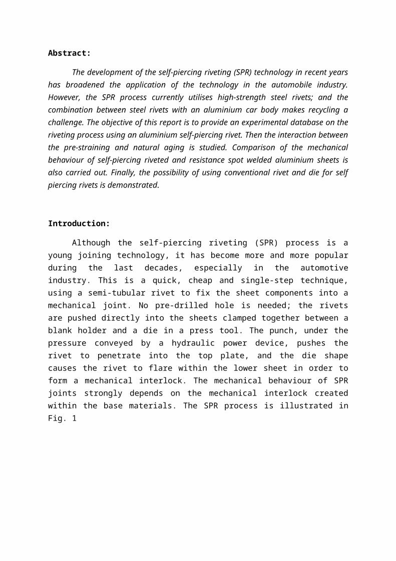
Although the self-piercing riveting (SPR) process is a young joining technology, it has become more and more popular during the last decades, especially in the automotive industry. This is a quick, cheap and single-step technique, using a semi-tubular rivet to fix the sheet components into a mechanical joint. No pre-drilled hole is needed; the rivets are pushed directly into the sheets clamped together between a blank holder and a die in a press tool. The punch, under the pressure conveyed by a hydraulic power device, pushes the rivet to penetrate into the top plate, and the die shape causes the rivet to flare within the lower sheet in order to form a mechanical interlock. The mechanical behaviour of SPR joints strongly depends on the mechanical interlock created within the base materials. The SPR process is illustrated in Fig. 1
Fig. 1 SPR process.
Optimum joining conditions have been obtained for a conventional rivet and die used for joining these materials. The optimisation of the riveting process has been conducted both through experimental tests in the laboratory and numerical simulations. The latter has taken a big step forward in recent years, leading to significant improvement in process design as well as cost reduction
The mechanical behaviour of self-piercing riveted connections using an aluminium rivet was investigated. Two U-shaped specimens in alloy AA6063-W, obtained by a solution heat treatment of the alloy in temper T4, were joined using an aluminium self-pierce rivet in alloy AA7278-T6. The mechanical behaviour of these connections was tested after 3 and 30 days of natural aging of the riveted specimens. Test results showed that the strength of the aluminium riveted joints tended to stabilize after three days of natural aging.
A limitation of this technology is still the heavy experimental procedure needed for joint optimisation. In this paper, an experimental activity on Al6082-T4 sheet metal samples has been conducted to achieve a better understanding of the process. The joining process and the tensile tests have then been simulated using a FE code to predict deformed shape, failure mechanism (e.g. crack propagation, rivet pull-out) and shear resistance of the joint. Results show how this procedure can be a powerful tool for joint optimisation.
The increased application of lightweight materials, such as aluminium has initiated many investigations into new joining techniques for aluminium alloys. The resistance spot welding (RSW) concept for aluminium has always attracted many researchers from different organizations. Self-piercing riveting (SPR) is the major production process used to join aluminium sheet body structures for the automotive industry. The research team has investigated these two major joining technologies for aluminium assembly. The paper reported here gives an in depth comparison of the mechanical behaviour for each joint type under different loading conditions
Methodology:
Self-piercing riveting connections using aluminium rivets:
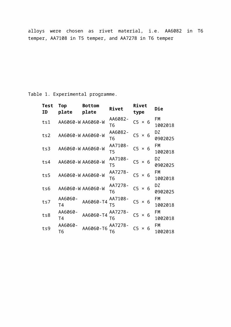
An extensive test programme was established in order to investigate the SPR of two 2 mm thick aluminium sheets using an aluminium self-piercing rivet, and is presented in Table 1. Plates to be joined were cut from extrusion of aluminium alloy 6060 in two different tempers, i.e. temper T6 and temper T4. However, the temper W was also tested, and was obtained by heat treatment of sheets in T4 temper followed by an immediate quenching in cool water. The rivets were of the Boellhoff type, and were machined using a lathe from the central part of an extruded cylindrical rod made of three aluminium alloys, i.e. 6082 in temper T6, 7108 in temper T5, and 7278 in temper T6. In addition, two conventional dies according to the Boellhoff standards were used in order to study the influence of the die shape. The geometries of the rivet and the die are given in Fig. 2 and Table 2. Nine combinations of the riveted specimens were finally selected in the test programme.
Aluminium alloy AA6060 in three different tempers, i.e. temper W, temper T4, and temper T6 was chosen as plate material in the present study. Three commercial aluminium alloys were chosen as rivet material, i.e. AA6082 in T6 temper, AA7108 in T5 temper, and AA7278 in T6 temper
Table 1. Experimental programme.
Test ID Top plate Bottom plate Rivet Rivet type Die
ts1 AA6060-W AA6060-W AA6082-T6 C5 × 6 FM 1002018
ts2 AA6060-W AA6060-W AA6082-T6 C5 × 6 DZ 0902025ts3 AA6060-W AA6060-W AA7108-T5 C5 × 6 FM 1002018ts4 AA6060-W AA6060-W AA7108-T5 C5 × 6 DZ 0902025ts5 AA6060-W AA6060-W AA7278-T6 C5 × 6 FM 1002018ts6 AA6060-W AA6060-W AA7278-T6 C5 × 6 DZ 0902025ts7 AA6060-T4 AA6060-T4 AA7108-T5 C5 × 6 FM 1002018ts8 AA6060-T4 AA6060-T4 AA7278-T6 C5 × 6 FM 1002018ts9 AA6060-T6 AA6060-T6 AA7278-T6 C5 × 6 FM 1002018
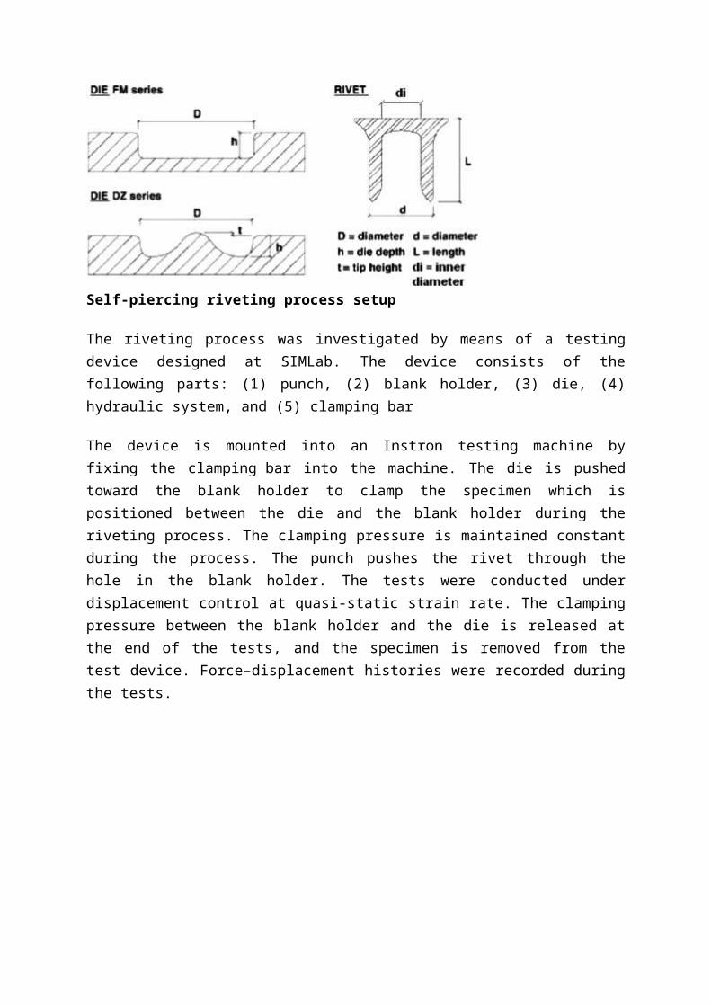
Self-piercing riveting process setup
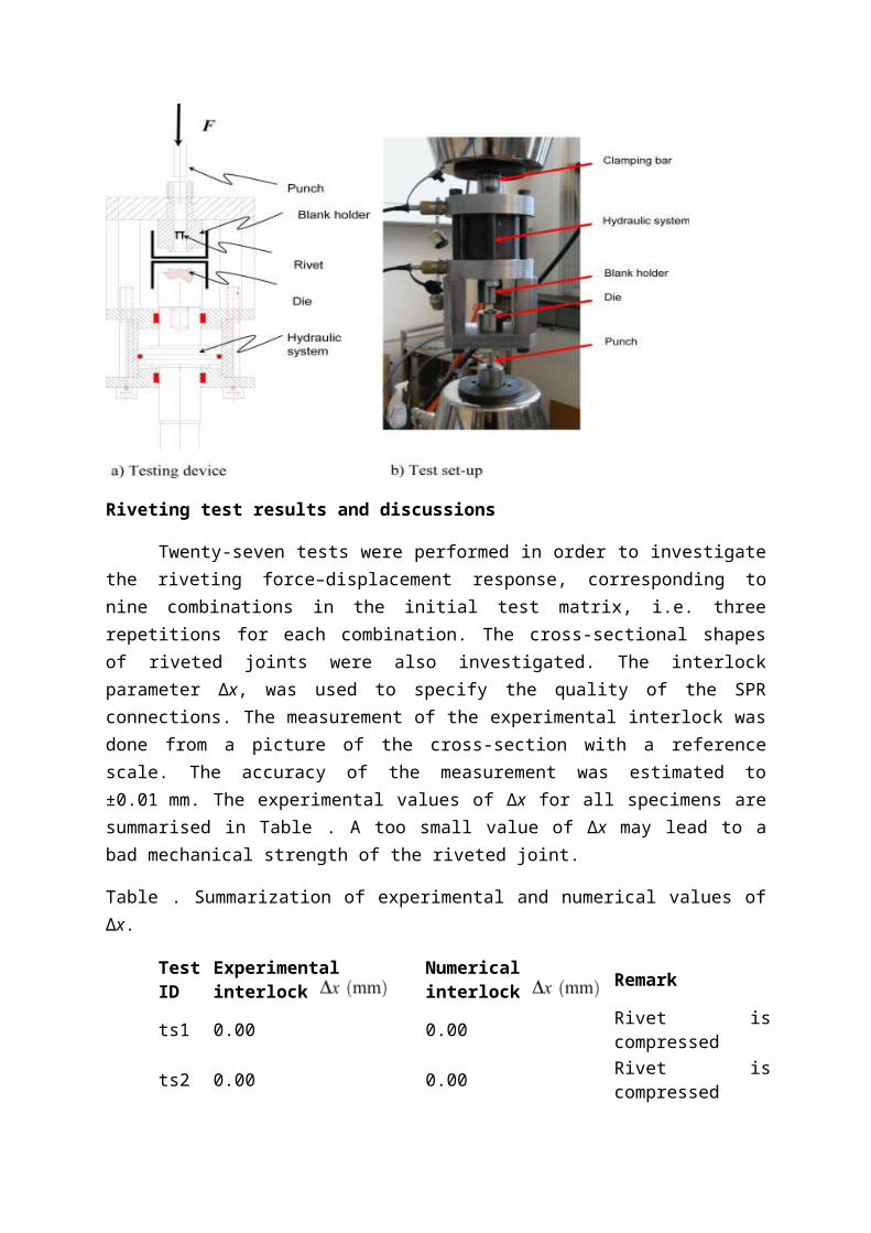
The riveting process was investigated by means of a testing device designed at SIMLab. The device consists of the following parts: (1) punch, (2) blank holder, (3) die, (4) hydraulic system, and (5) clamping bar
The device is mounted into an Instron testing machine by fixing the clamping bar into the machine. The die is pushed toward the blank holder to clamp the specimen which is positioned between the die and the blank holder during the riveting process. The clamping pressure is maintained constant during the process. The punch pushes the rivet through the hole in the blank holder. The tests were conducted under displacement control at quasi-static strain rate. The clamping pressure between the blank holder and the die is released at the end of the tests, and the specimen is removed from the test device. Force–displacement histories were recorded during the tests.
Riveting test results and discussions
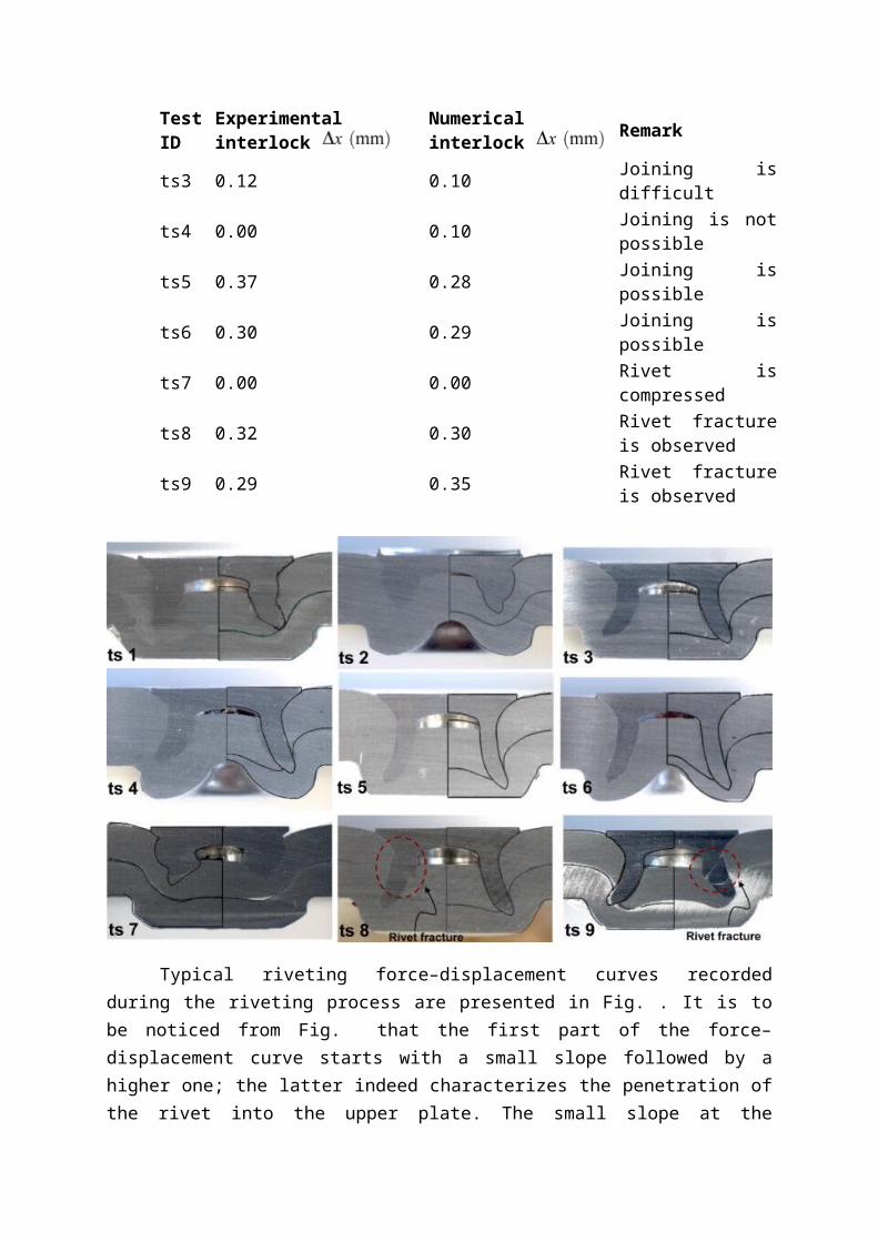
Twenty-seven tests were performed in order to investigate the riveting force–displacement response, corresponding to nine combinations in the initial test matrix, i.e. three repetitions for each combination. The cross-sectional shapes of riveted joints were also investigated. The interlock parameter Δx, was used to specify the quality of the SPR connections. The measurement of the experimental interlock was done from a picture of the cross-section with a reference scale. The accuracy of the measurement was estimated to ±0.01 mm. The experimental values of Δx for all specimens are summarised in Table . A too small value of Δx may lead to a bad mechanical strength of the riveted joint.
Table . Summarization of experimental and numerical values of Δx.
Test ID
Experimental interlock Numerical interlock Remark
ts1 0.00 0.00 Rivet is compressedts2 0.00 0.00 Rivet is compressedts3 0.12 0.10 Joining is difficultts4 0.00 0.10 Joining is not possiblets5 0.37 0.28 Joining is possiblets6 0.30 0.29 Joining is possiblets7 0.00 0.00 Rivet is compressed
ts8 0.32 0.30Rivet fracture is observed
ts9 0.29 0.35Rivet fracture is observed
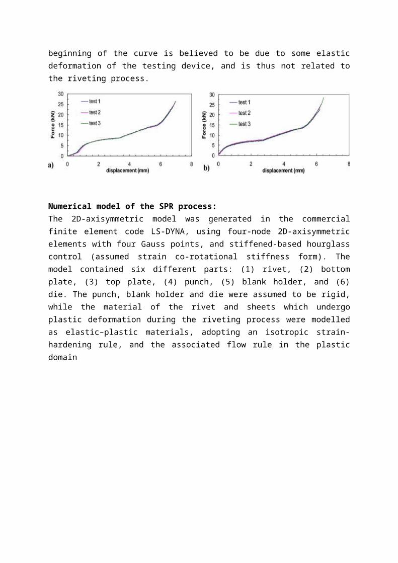
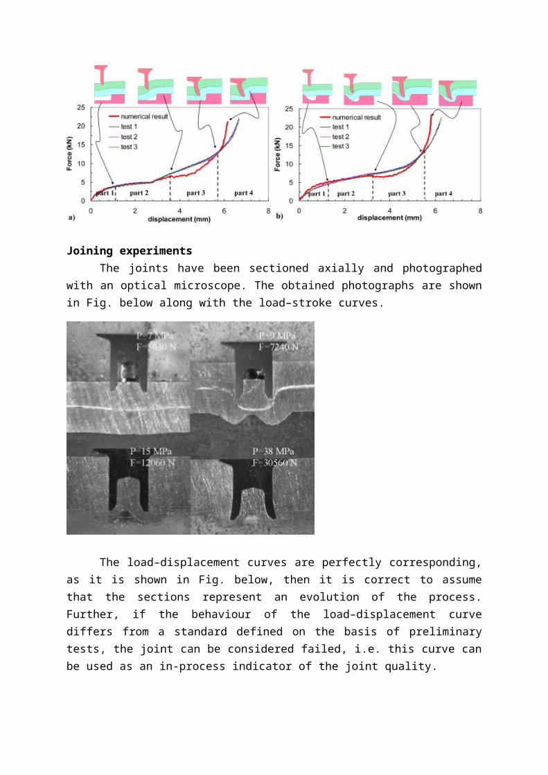
Typical riveting force–displacement curves recorded during the riveting process are presented in Fig. . It is to be noticed from Fig. that the first part of the force–displacement curve starts with a small slope followed by a higher one; the latter indeed characterizes the penetration of the rivet into the upper plate. The small slope at the beginning of the curve is believed to be due to some elastic deformation of the testing device, and is thus not related to the riveting process.
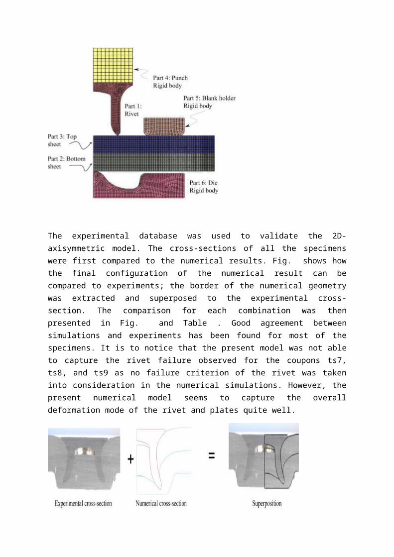
Numerical model of the SPR process:The 2D-axisymmetric model was generated in the commercial finite element code LS-DYNA, using four-node 2D-axisymmetric elements with four Gauss points, and stiffened-based hourglass control (assumed strain co-rotational stiffness form). The model contained six different parts: (1) rivet, (2) bottom plate, (3) top plate, (4) punch, (5) blank holder, and (6) die. The punch, blank holder and die were assumed to be rigid, while the material of the rivet and sheets which undergo plastic deformation during the riveting process were modelled as elastic–plastic materials, adopting an isotropic strain-hardening rule, and the associated flow rule in the plastic domain
The experimental database was used to validate the 2D-axisymmetric model. The cross-sections of all the specimens were first compared to the numerical results. Fig. shows how the final configuration of the numerical result can be compared to experiments; the border of the numerical geometry was extracted and superposed to the experimental cross-section. The comparison for each combination was then presented in Fig. and Table . Good agreement between simulations and experiments has been found for most of the specimens. It is to notice that the present model was not able to capture the rivet failure observed for the coupons ts7, ts8, and ts9 as no failure criterion of the rivet was taken into consideration in the numerical simulations. However, the present numerical model seems to capture the overall deformation mode of the rivet and plates quite well.
Joining experimentsThe joints have been sectioned axially and photographed with an optical microscope.
The obtained photographs are shown in Fig. below along with the load–stroke curves.
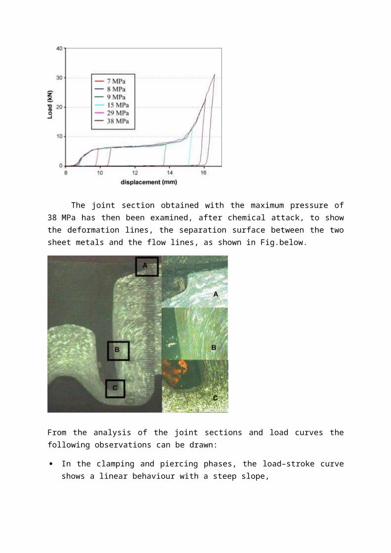
The load–displacement curves are perfectly corresponding, as it is shown in Fig. below, then it is correct to assume that the sections represent an evolution of the process. Further, if the behaviour of the load–displacement curve differs from a standard defined on the basis of preliminary tests, the joint can be considered failed, i.e. this curve can be used as an in-process indicator of the joint quality.
The joint section obtained with the maximum pressure of 38 MPa has then been examined, after chemical attack, to show the deformation lines, the separation surface between the two sheet metals and the flow lines, as shown in Fig.below.
From the analysis of the joint sections and load curves the following observations can be drawn:
In the clamping and piercing phases, the load–stroke curve shows a linear behaviour with a steep slope,
In a second moment the rivet pierces the top sheet and the lower sheet flows into the die. This corresponds to the second part of the stroke–displacement curve, with a lesser slope,
In the flaring phase, the curve rises with a higher gradient,
As the rivet head compresses the upper sheet surfaces, the curve slope increases and, as the die cavity is filled, the gradient of the load curve corresponds to the stiffness of the tool-sheet-press system.
The process is completed in about 0.9 s and the average strain rate is in the order of 2.6 s−1.
Symmetrical stacks – analysis of T-peel results
The SPR joints generally achieved higher or similar T-peel strengths than the RSW samples in the three symmetrical stacks tested. This is attributed to the interlock feature of an SPR type joint. In these tests two different failure modes were observed. Rivet pull-out failure, as shown in the example Fig. 7a, occurred when the rivet interlocked into the bottom sheet was pulled out during the test. This type of failure indicates that the interlock dominates the joint strength. All (1 + 1) samples failed by the rivet pull-out indicating a weak interlock. For the thicker gauge stacks, there is more material present and it is easier to obtain a good interlock strength, which can exceed the tearing resistance of the parent sheet. Consequently, the failure mode can change to sheet pull out as the head of the rivet is pulled through the sheet. This failure mode was observed for some rivet and die combinations for (2 + 2) and (3 + 3) stacks, as shown in Fig. 7b. For RSW samples failure occurred as the sheet material was peeled away along the Heat affected zone (HAZ) leaving a plug of material containing the untouched nugget, as shown in Fig. 7c. This failure mode suggests that the RSW T-peel strength is governed by the tearing r esistance of the sheet material (providing the nugget is sufficient strong to sustain the load or else shear/interfacial failure occurs). Although the peel strength increased with nugget diameter, the increment was not as significant as that seen for shear strength.
Conclusions:
A proper joint can be obtained when using a rivet in alloy 7278-T6 to join two plates in alloy 6060-W.
Aluminium SPR joints can provide a good static strength in comparison with the steel ones. A difference in strength of approximately 10% was reported.
An optimised die shape leads to a riveted joint with a better quality.
The simulation results were in good agreement with the experiments, both with respect to the force–displacement curves as well as the cross-sectional shapes of the rivet and plates.
After 3 days of natural aging, the strength of the aluminium riveted connections trend to stabilize
SPR joints generally achieved similar or higher peel strengths than the RSW samples.
References:
[1]N.-H. Hoang, R. Porcaro, M. Langseth, A.-G. Hanssen, "Self-piercing riveting connections using aluminium rivets", Int. J. Solids and Structures, Volume 47, Issues 3–4, February 2010
[2]Y. Abe, T. Kato, K. Mori, "Self-piercing riveting of high tensile strength steel and aluminium alloy sheets using conventional rivet and die ", J. Materials Processing Technology, Volume 209, Issue 8, 21 April 2009
[3]N.-H. Hoang, M. Langseth, R. Porcaro, A.-G. Hanssen, "The effect of the riveting process and aging on the mechanical behaviour of an aluminium self-piercing riveted connection" , European J. of Mechanics and Solids, Volume 30, Issue 5, September–October 2011
[4]E. Atzeni, R. Ippolito, L. Settineri, Experimental and numerical appraisal of self-piercing riveting, CIRP Annals - Manufacturing Technology, Volume 58, Issue 1, 2009
[5]L. Han, M. Thornton, M. Shergold, A comparison of the mechanical behaviour of self-piercing riveted and resistance spot welded aluminium sheets for the automotive industry, Materials & Design, Volume 31, Issue 3, March 2010
[6]Giuseppe Di Franco, Livan Fratini, Antonino Pasta, Influence of the distance between rivets in self-piercing riveting bonded joints made of carbon fiber panels and AA2024 blanks, Materials & Design, Volume 35, March 2012
[7]P.K.C. Wood, C.A. Schley, M.A. Williams, A. Rusinek, A model to describe the high rate performance of self-piercing riveted joints in sheet aluminium, Materials & Design, Volume 32, Issue 4, April 2011
[8]Dong XIAO, Xiao-li PAN, Yong YUAN, Zhi-zhong MAO, Fu-li WANG, Modeling and Optimization for Piercing Energy Consumption, Journal of Iron and Steel Research, International, Volume 16, Issue 2, March 2009
[9]D. Li, L. Han, M. Thornton, M. Shergold, Influence of edge distance on quality and static behaviour of self-piercing riveted aluminium joints, Materials & Design, Volume 34, February 2012
[10] A.G. Hanssen, L. Olovsson, R. Porcaro, M. Langseth, A large-scale finite element point-connector model for self-piercing rivet connections, European Journal of Mechanics - A/Solids, Volume 29, Issue 4, July–August 2010