Embed Size (px)
Citation preview

Control and stability analysis of VSC-HVDC based transmission system connected to
offshore wind farm
Ali Haghi1, Mohsen Rahimi
2
1,2 Department of Electrical and Computer Engineering, University of Kashan, Kashan, Iran
1,2 P. O. Box: 87317-53153, Phone: +9831 55913469, Mobile: 09127057737
Email: [email protected],
Abstract
Offshore wind farms (WFs) with significant capacities have been installed recently all over the world. In order to transmit the WF
power to the onshore grid, high voltage direct current (HVDC) transmission system is appropriate technology. This paper
analytically studies the impact of system parameters, controllers and operating conditions on the dynamic behavior of HVDC
transmission systems based on three-level neutral point clamped voltage source converters (VSC). Also, it investigates modeling,
control and stability analysis of VSC-HVDC system connected to the offshore wind farms. The VSC-HVDC system comprises
offshore and onshore converters and high voltage dc transmission lines. The paper extracts VSC-HVDC system dynamics at the
dc-side and argues the interaction between onshore converter control and HVDC transmission line dynamics. Moreover, the
paper presents controller design for the dc-link voltage regulation by the onshore converter and examines the impacts of HVDC
line length and dc voltage control bandwidth (BW) on the system stability by the modal analysis and time domain simulations.
Keywords: Integration of wind power generation, voltage source converters (VSC), high-voltage direct-current (HVDC) lines, offshore wind
farms, DC-link voltage regulation.
1. Introduction
Offshore wind farms have many advantages over traditional onshore wind farms. Namely, the availability of
higher wind speed, simplicity of high wind power transmission, and limited available inland locations to install new
wind farms in some countries make offshore wind farms a promising alternative [1]. Hence, offshore wind farms had
significant growth in recent years. 3.148 GW of offshore wind power capacity was connected to the grid during 2017
in Europe. This corresponds to 560 new offshore wind turbines across 17 wind farms [2]. Also, 1.558 GW of new
offshore wind power capacity was connected to the grid during 2016 in Europe and this is a 48.4% decrease
compared to 2015 [3].
In order to facilitate the transfer of large electrical power generated by offshore wind farms to the grid, HVDC
system plays an important role. Multilevel voltage source converter (MVSC) topologies have received raised
attention in recent years for the connection of offshore wind power to the local grid [4]. HVDC system with fast and
flexible power flow control provides electrical grid reliability and security. In addition, offshore wind farms are
usually located far from the local grid. Therefore, the power produced by offshore wind farms needs long

2 A. Haghi, M. Rahimi: Control and stability analysis of wind farm connected to VSC-HVDC transmission system
2
transmission lines to transmit the generated electricity to the consumers. For such offshore grid, application of high-
voltage alternating current (HVAC) technology is not possible, because with the increase in transmission distance,
the reactive power flow will be higher due to line capacitances, which will result in large line losses [5-7]. Therefore,
HVDC transmission line is considered a key technology for this purpose. The main feature of transmission system
based on VSC-HVDC is its ability for independent control of active and reactive power flow in each of the AC grids
as addressed in [8-12].
In last few years, HVDC transmission systems were based on current source converters (CSCs). CSC uses line-
commutated switching device which has some limitations. For example, it needs reactive power compensation
devices resulting in a bulk converter station. Modern HVDC transmission systems employ VSCs which use self-
commutated devices. This means that in VSC, the current can lead or lag the ac voltage, so the converter can
consume or supply reactive power to the connected ac grid eliminating the reactive power compensation devices [13,
14]. Furthermore, higher switching frequency of pulse-width modulation (PWM) reduces the filtering requirements
and power flow can be reversed without the need to reverse the dc-link voltage. All these advantages show that the
VSC is an appropriate option for HVDC transmission systems.
Several papers have dealt with the modeling, control and performance analysis of the VSC-HVDC systems
connected to offshore wind farms. Paper [15] deals with the operation and control of an offshore wind farm
connected to an HVDC system, and adopts a fuzzy logic controller for the offshore VSC station. In this paper,
stability of the HVDC system under developed control schemes is dynamically and transiently investigated. In [16],
modal and stability analysis of a VSC-HVDC based offshore wind farm is presented to study the nature of different
oscillatory modes that are present in the wind farm system. However, [15-16] do not examine the impact of HVDC
system parameters on system stability. [17] deals with the coordinated control of VSC-HVDC system in order to
inertia support of the main grid. The inertia support is performed through utilization of wind turbine inertia together
with the HVDC system capacitors. In this article, studies are carried out for a wind farm connected to an HVDC
considering sudden load variations to compare and demonstrate the effectiveness of the control strategies. The
stability of the HVDC system and the factors affecting it have not been investigated in this paper. Also, [18] deals
with the integration of a DFIG based offshore wind farm to a weak onshore grid through VSC-HVDC transmission
system by using a new approach, known as power-synchronization method. In this paper, onshore and offshore faults
are considered and the fault-ride through techniques are presented, but the impact of grid short-circuit power on the
dc-link dynamic stability of the system has not been discussed. In [19], a new configuration for the voltage source
converter of the VSC-HVDC system is proposed to enhance the low voltage ride-through capability and smooth
power injection to the grid. This article does not investigate the impact of grid short-circuit power and VSC-HVDC
system parameters on VSC-HVDC system stability. In [20], a flywheel energy storage system is implemented for
LVRT support of grid connected VSC-HVDC based offshore wind farms. The purpose of this Ref. is to provide a
reliable VSC-HVDC transmission system architecture between offshore wind farms and onshore grids.
Hence, according to the reviewed papers related to the VSC-HVDC based wind farms, less analytical researches
have been published regarding the system parameters and variables affecting the DC side stability. This paper deals
with the modeling, control and stability analysis of VSC-HVDC system connected to offshore wind farms. The
system under study comprises two 90 MW wind farms connected to onshore grid via VSC-HVDC transmission
system, where each wind farm includes forty five 2 MW PMSG based wind turbines. In this way, the paper first
deals with the control of the offshore and onshore converters and then mathematical modeling of the VSC-HVDC
system and dc-link dynamics is presented. The offshore converter provides three-phase voltage with constant voltage
and frequency and transmits the wind farm delivered power to the VSC-HVDC system. The onshore converter
regulates the dc-link voltage and exchanges reactive power with the onshore grid.
Next, the paper examines the impacts of HVDC transmission line length and dc-voltage control bandwidth on the
system stability by the modal analysis and time domain simulations. Also, the paper investigates the impact of
onshore grid short circuit power on the dc-link dynamic stability.
Hence, the main purpose of this article is to study the stability of the dc-link dynamics in VSC-HVDC system and
examine the impacts of the HVDC transmission line length and dc-voltage control bandwidth on the dc side stability

3
3
by the modal analysis and time domain simulations.
2. Under study system Layout
Fig. 1 shows the layout of the study system that includes onshore grid, transformers, converters, dc cables and
wind farms. In the system under study of Fig. 1, two wind farms with a capacity of each 90 MW power generation
are separately connected to VSC-HVDC transmission system. The HVDC transmission line parameters for this
system are given in Appendix A (Table A1). Each wind farm includes forty five 2 MW full scale converter wind
turbines with 690 V rated voltage. Onshore grid is a 230 kV, 2000 MVA and 50 Hz AC system modeled by an ideal
voltage source in series with R-L impedance, where the grid impedance angle at 50 Hz is equal to 80o.
There are several possible converter arrangements in an HVDC transmission system, which based on the number
of converters used at each terminal, can be divided into monopole and bipolar configurations. In monopole
configuration, only one converter is used at each end of the network. Because of this characteristic, this method is
more cost effective, while the bipolar configuration employs two converters at each terminal. On the AC side they
are powered either by two different transformers, or by a transformer with two secondary windings. Monopolar
configurations are divided into symmetric monopole, asymmetric monopole with metallic return and asymmetric
monopole with ground return configurations [21, 22]. The under study system in this paper is based on symmetric
monopole HVDC line configuration.
Among the different types of voltage source converters (VSCs) such as two-level, three-level and modular
multilevel converter (MMC), the three-level VSCs with switching frequency of 1350 Hz are used as the offshore and
onshore converters. A 20kV
/100kV
transformer is used between the wind farm grid and offshore converter, and a
100kV
/230kV
transformer is used between the onshore converter and onshore grid. At the ac sides of both onshore and
offshore converters, phase reactors with the size of 0.15 pu (0.0477 H) are used. In most cases like this, cross-linked
polyethylene (XLPE) cables are used in VSC-HVDC transmission systems. XLPE has many benefits such as strong
mechanical strength, flexibility and low weight. The XLPE cable is mainly composed of conductor, insulation, water
barrier, armouring and outer sheath [23].
3. Offshore and onshore converters control
Generally, there are two main converters in the wind farm VSC-HVDC system known as offshore and onshore
converters. By offshore converter, AC voltage with fixed amplitude and frequency will be provided for the wind
farm offshore grid. The offshore converter absorbs power produced by offshore wind farms installed in the sea and
transmits it into HVDC transmission system. At the end of HVDC line, active power will be transferred to the ac
onshore grid by the onshore converter.
3.1. Offshore converter controller
There are several ways to control the offshore converter. A simple method is direct control of AC voltage
magnitude that is used in [24] and [25]. Fig. 2 shows a block diagram of offshore converter control. In this figure,
there is an AC voltage direct control loop keeping the amplitude and frequency of the AC bus voltage constant,
through modulation index (M).
This control method has some restrictions, such as [26]: (1) there is no current loop control, thus limiting the
converter current is difficult (2) the controller parameters have a great impact on the behavior of the offshore
converter, and in the event that the controller is not adjusted properly, there will be some transients at system
response. In order to overcome these limitations, this article uses cascaded controllers including inner current control
loop and outer voltage control loop. By the outer voltage control loop, the reference current for the inner current
control loop is provided. The inner current control loop determines the converter output voltage in a manner that
provides voltage with suitable frequency and amplitude for offshore AC grid. These controllers are PI type and are

4 A. Haghi, M. Rahimi: Control and stability analysis of wind farm connected to VSC-HVDC transmission system
4
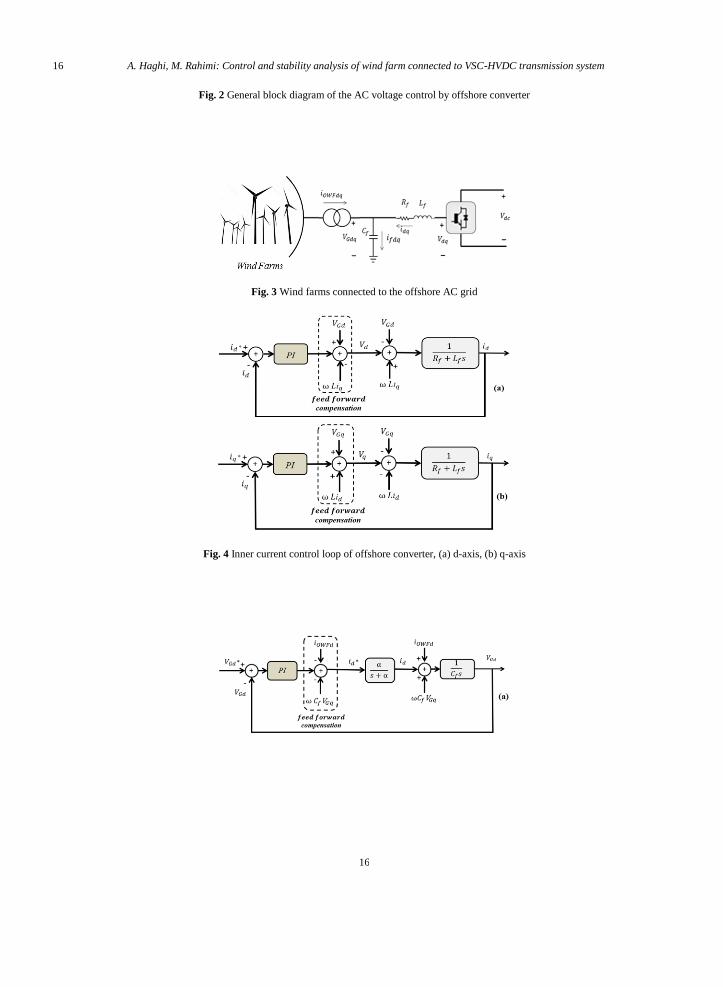
implemented in the dq synchronous reference frame. Fig. 3 shows the offshore converter and wind farm connected
to the offshore AC grid.
Dynamic equations of the offshore converter in the dq- reference frame are given as follows:
f Gd OWFd d f Gq
d
dtC v i i C v (1)
f Gq OWFq q f Gd
d
dtC v i i C v (2)
f fd d Gd qd
dfdtiRi v v iL L (3)
f fq q Gq dq
dfdtiRi v v iL L (4)
where vGd and vGq represent the dq components of the offshore grid voltage, iOWFd and iOWFq denote the dq
components of the offshore wind farm current, id and iq are the dq components of offshore converter output current,
vd and vq represent the dq components of the offshore converter output voltage, ω is the fundamental frequency of
the offshore converter, and Cf and Lf represent the capacitance and inductance of the converter interface LC filter. In
the following, the inner current and outer voltage control loops of the offshore converter are presented. Figures 4(a)
and 4(b) show the inner dq current control loops of the offshore converter, where vd and vq as the offshore converter
output voltages are given by:
* *
1 1( ) ( )
fd Gd q p d d i d dv v i k i i k i iL (5)
* *
1 1( ) ( )
fq Gq d p q q i q qv v i k i i k i iL (6)
where ki1 and kp1 are the PI controller parameters.
It is noted that in Figs. 4(a) and 4(b), the terms Gdv ,
qLi and Gqv and
dLi act as disturbances, and thus to
improve the dynamics of the current control loops, they are compensated by the feedforward terms.
Also, Figs. 5(a) and 5(b) depict the outer dq voltage control loops of the offshore where α/(s+α) is the closed loop
transfer function (TF) of the inner current loop. Hence, is the closed loop bandwidth of the converter inner
current control loop. is a design parameter and is roughly selected as sw , where
sw denotes the conveter
switching frequency. For the system under study, is selected equal to 2 100 rad/sec or 100 Hz.
The dq voltage controllers provide the reference currents id* and iq* as given below:
* * *
2 2( ) ( )
d OWFd f Gq p Gd Gd i Gd Gdi i C v k v v k v v (7)
* * *
3 3( ) ( )
q OWFq f Gd p Gq Gq i Gq Gqi i C v k v v k v v (8)
where ki2, ki3, kp2 and kp3 are PI controllers parameters.
In the control loops of Figs. 5(a) and 5(b), the terms OWFDi ,
f GqC v and OWFQi and f GdC v act as disturbances,
and similar to Fig. 4, they are compensated by the feedforward terms.
More details for the design of the inner and outer loop controllers are available in [27]. Figure 6 depicts the
overall control block diagram of the offshore converter.

5
5
3.2. Onshore converter controller
Under normal operating conditions, the purpose of the onshore converter control is the dc-link voltage regulation
that enables power transmission from the wind farm to the grid. Onshore converter can also exchange reactive power
with the onshore grid. Figure 7 shows the onshore converter connected to the onshore grid through the interface Rg-
Lg filter.
The dynamic model of the onshore converter in the dq synchronous reference frame is given as:
( )gd
g gq g g gdd Gd
d
dt
iU U L i L R i (9)
( )gq
g gd g g gqq Gq
d
dt
iU U L i L R i (10)
where Uq and Ud are the converter output voltages, UGd and UGq are onshore grid voltages, igd and igq
are converter output currents, Lg and Rg represent the interface filter inductance and resistance, and ω is the onshore
grid frequency. To facilitate the controller design, the d-axis is adapted to the onshore grid AC voltage and q-axis is
90° ahead of the d-axis, and thus, UGd=UG and UGq=0 and task of igd is the DC-link voltage
regulation, and task of igq is regulation of reactive power injected to the onshore grid. Similar to the offshore
converter, the onshore converter is controlled by the cascaded control approach comprising the inner current control
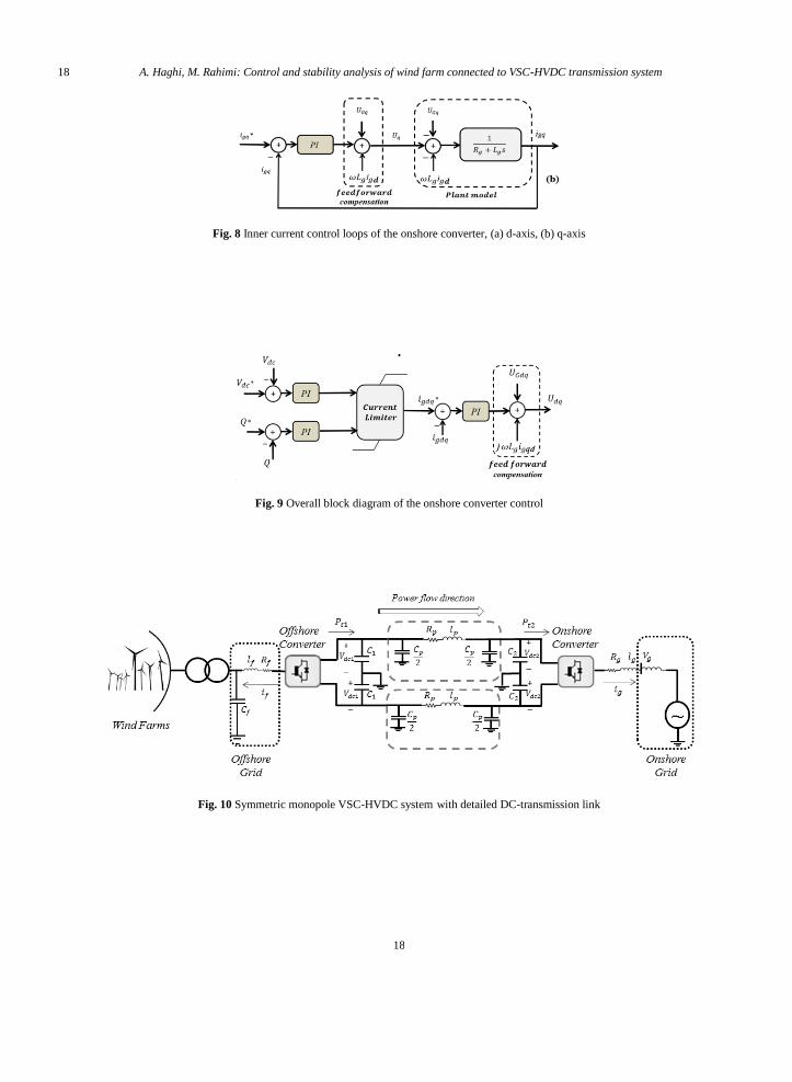
loops, and outer DC-link and reactive power control loops. Figures 8(a) and 8(b) show the onshore converter inner
current control loops. Also, Fig. 9 depicts the overall control scheme of the onshore converter comprising the outer
DC-link voltage and reactive power loops.
Considering Fig. 9, the dq reference currents igd* and igq* are given as:
* * *
1 1( ) ( )
gd pdc dc dc idc dc dci k v v k v v (11)
* * *
2 2( ) ( )
gq pdc idcQ Q Q Qi k k (12)
where kpdc1, kpdc2, kidc1 and kidc2 are the PI controllers parameters.
4. Stability analysis of VSC-HVDC grid and onshore converter controller
This section deals with the stability analysis of the system at the DC-side and DC-link voltage controller design
for the onshore converter. Since controller parameters affect on the DC grid dynamics of the HVDC system, after
controller design, dynamic analysis of the DC grid is also performed. In this way, state equations of the HVDC
system are extracted and impacts of the DC-link control bandwidth, length of HVDC transmission line and short
circuit power of the onshore AC grid on the stability and performance of the HVDC system are examined.
Figure 10 shows the structure of the VSC-HVDC system used in the system under study of Fig. 1, which is a
symmetrical monopole VSC-HVDC system. For analysis and modeling of the DC-side dynamics, the equivalent
model shown in Fig. 11 can be used that is an asymmetric monopole model with the ground return. In Fig. 10, cables
of the HVDC transmission system are modeled by the π model. Each onshore or offshore converter has C1 and C2
capacitors in the DC-side. Onshore converter through the inductive filter with Lg inductance and Rg resistance is
connected to the AC grid. Also offshore converter is connected to the wind farm through LC filter. In Fig. 11,
P1=Pt1 / 2, P2=Pt2 / 2, where according to Fig. 10, Pt1 and Pt2 are the offshore grid output power and onshore grid
input power, respectively.

6 A. Haghi, M. Rahimi: Control and stability analysis of wind farm connected to VSC-HVDC transmission system
6
4.1. State equations of the open loop VSC-HVDC system
In order to extract state equations and modal analysis of the HVDC system, the equivalent model of the DC-
transmission link given in Fig. 11 is considered. Considering Fig. 11, simplified model of the VSC-HVDC system of
Fig. 11 is obtained as depicted in Fig. 12. where Ct1=C1+Cp/2, Ct2=C2+Cp/2. According to the Fig. 12, state equations of the DC-side are given by:
1
1 1
dc
t dcdt
dVC i i
1 2
dc
p p dc dc dcdt
dii V VL R (13)
2
2 2
dc
t dcdt
dVC i i
where in (13) 1
1
1dc
Pi
V and 2
2
2dc
Pi
V . By Linearizing Eq. (13) around operating point, we have:
1
1 1
dc
t dcdt
d VC i i
1 2
dc
p p dc dc dcdt
d ii V VL R
(14)
2
2 2
dc
t dcdt
d VC i i
where Δ denotes the small deviation around the operating point. In (14), Δi1 and Δi2 are given as
101121
10 20
dc
dc dc
VPPi
V V
and 202
222
20 20
dc
dc dc
VPPi
V V
. Replacing Δi1 and Δi2 with the corresponding expressions, the state
equations of Eq. (14) can be given as:
1 101
21 1
10 10
dc
t dc dc
dc dcdt
d V PPC V i
v v
1 2
dc
p p dc dc dcdt
d ii V VL R
(15)
2 202
22 2
20 20
dc
t dc dc
dc dcdt
d V PPC i V
V V
From Eq. (15), the equivalent small signal model of the VSC-HVDC system is obtained as depicted in Fig. 13,
where in Fig. 13, 2
20
10
10
0dcVR
P and
2
20
20
20
0dcVR
P .
Dynamic equations of Eq. (15) can be written in the form of ,x A x B u y C x , where A is a 3×3 matrix and
1 2[ ]T
dc dc dcx V i V , 1 2[ ]Tu P P and 2dcy V .
7
7
In the mentioned state equations of Eq. (15), ΔP2 is the control input used to regulate Vdc2 at the desired value and
ΔP1, also acts as the disturbance. From Eq. (15), the open loop transfer function G(s) from -ΔP2 to ΔVdc2 is given by:
1 1 2
2,0 1 4 3 1 42
3 2
2 1 2 4 3 1 4 1 2 2 4 1 3 2 3 1 2 4
[ ( ) ( )]( )
( ) [2 ] ( )
t dcdcC V s sV
G sP s s s
(16)
Transfer function of Eq. (16) can be represented as depicted in Fig. 14:
Similarly, the transfer function from ΔP1 to ΔVdc2 can be written as follows:
1 1
3 2,02
3 2
1 1 2 4 3 1 4 1 2 2 4 1 3 2 3 1 2 4
( )( ) [2 ] ( )
t dcdcC VV
D sP s s s
(17)
In Eq. (16) and Eq. (17),1
10
1
tC R ,
2
20
1,
tC R
3
1
p tL C and 4
p
p
R
L . Considering Fig. 10 and neglecting the
onshore converter losses, the power injected to the onshore grid is given by
2
3
2t gd gdP V i (18)
In Fig. 11, P2 = Pt2 / 2 and thus we have
2
1 3
2 2gd gdP V i (19)
To obtain ΔP2 in Eq. (19), it is assumed that the onshore grid is sufficiently stiff and ΔVgd ≈0. According to Eq.
(16) and Eq. (19) and Fig. 14, the closed loop control system of the DC-link voltage at the onshore side is obtained
as depicted in Fig. 15.
The transfer function G(s) in Fig. 15 is the one presented in Eq. (16). If the impacts of the HVDC transmission
line dynamics on the DC-link dynamics of the onshore converter is ignored, the transfer function G(s) will be
changed to the simple form of Eq. (20).
21
2 20
( ) 1( )
( )
dc
t dc
V sG s
P s CV s
(20)
4.2. DC-link voltage control design
As previously mentioned, the task of the onshore converter is regulation of the DC-link voltage in the reference
value and transferring the wind farms power to the onshore AC grid. There are two approaches for selection of the
DC-link controller parameters:
a) Considering the simple transfer function of Eq. (20) without taking the HVDC transmission line dynamics
into account.
b) Considering the whole system dynamics and using the transfer function of Eq. (16).
Since the first approach is easier, in this section DC-link controller is designed based on the simple transfer
function of Eq. (20). Fig. 16 shows the closed loop block diagram of the DC-link voltage control at the onshore
converter side using the simple transfer function.

8 A. Haghi, M. Rahimi: Control and stability analysis of wind farm connected to VSC-HVDC transmission system
8
After selection of the DC-link controller parameters, stability and performance of the whole HVDC-side
dynamics are investigated for the mentioned controller.
In Fig. 16, since the inner current control dynamics is much faster than the outer DC-link voltage control, the
term α/(s+α) can be replaced with 1. Consequently, the closed loop transfer function of Fig. 16 can be described by
2
2
* 2 2
2
2
2
dc n n
dc n n
V s
V s s
(21)
where
2
20
20
3
4
32
4
n gd idc
t dc
n gd pdc
t dc
v kC v
v kC v
(22)
where kpdc and kidc are the PI controller parameters. By selecting 0.7 and 85 / secn rad , the controller
parameters 2
20 208 4,
3 3
n t dc n t dcpdc idc
gd gd
C v C vk k
v v
, for the system under study with parameters of Appendix A (Table A1)
and 100 km HVDC transmission line, are obtained as kpdc= 0.011 and kidc=0.69.
4.3. Small signal stability analysis of the VSC-HVDC system
At this section, impact of DC-link controller and DC transmission line length on the HVDC system stability is
investigated. State equations of the HVDC side dynamics considering the outer DC-link voltage controller and inner
d-axis current dynamics are given by:
1 1 11
10 10
1 2
2 2 22
20 20
*
*
2 2
dc dct dc
dc
dcp p dc dc dc
dc dct dc
dc
gd
gd gd
dc dc dc
d V P VC i
dt V R
d iL R i V V
dt
d V P VC i
dt V R
d ii i
dt
x V V
(23)
where
2
* * *
2 2 2 2
3
4
( ) ( )
gd gd
gd pdc dc dc idc dc dc
P V i
i k V V k V V dt
(24)
By substituting (24) in (23), we have

9
9
1 1 11
10 10
1 2
02 22
20 20
*
2 2
*
2 2
3
4
dc dct dc
dc
dcp p dc dc dc
gddc dct dc gd
dc
gd
gd pdc dc pdc dc idc dc
dcdc dc
d V P VC i
dt V R
d iL R i V V
dt
Vd V VC i i
dt V R
d ii k V k V k x
dt
d xV V
dt
(25)
where xdc is the state variable related to the DC-link controller and α is the closed loop bandwidth of the inner
current control loop. State equations of Eq. (25) are in the form of x A x B u where A is a 5 × 5 state matrix and
the state vector (Δx) and input (Δu) are as *
1 2 1 2[ ] , [ ]T T
dc dc dc gd dc dcx V i V i x u P V .
Modal analysis shows that the dc-link control bandwidth and HVDC transmission line affect the system
dynamics. Modal analysis results for the different DC-link control bandwidths and HVDC transmission line lengths
briefly are presented in Table 1.
It is clear that at the line length equal to 100 km, the DC-link voltage of the system is stable at all DC-link control
bandwidths from 10 to 50 Hz. The results of the analysis show that the stability of the system is more affected at the
lower bandwidths. Also, modal analysis shows that increasing the line length while keeping the dc-link control
bandwidth constant, results in the modes with lower stability margin. Fig. 17 shows the bode diagram of the DC-link
control loop gain at 150 km transmission line length and for DC-link control bandwidths of 10 and 20 Hz.
According to Fig. 17, at 150 km line length and for DC-link control bandwidths of 10 and 20 Hz, the phase margin is
negative and the closed loop DC-link dynamics is unstable.
5. Simulation results
This section deals with the time domain simulation of the system under study of Fig. 1. The effects of the HVDC
transmission line length and DC-link control closed loop bandwidth on the stability and performance of the HVDC
system and the impact of short circuit power of the onshore AC grid on the DC-link voltage dynamics are examined
by simulation results.
5.1 Effects of the HVDC transmission line length and DC-link control closed loop bandwidth on the HVDC
system
Figs. 18 and 19 show the offshore and onshore converter responses at Vw=12 m/s, transmission line length of 100
km and DC-link control bandwidth of 50 Hz. Fig. 18 shows the output real power of the offshore converter
(transferred to the onshore converter), reactive power exchanged by offshore converter and DC-link voltage of the
offshore converter Vdc1. According to Fig. 18(a), 145 MW active power is transferred to the HVDC system by the
offshore converter. Fig. 18(b) specifies that the reactive power exchanged between the converter and offshore AC
grid is close to zero. DC-link voltage of offshore converter compared to the neutral point that is fixed on 1 pu is
shown in Fig. 18(c).
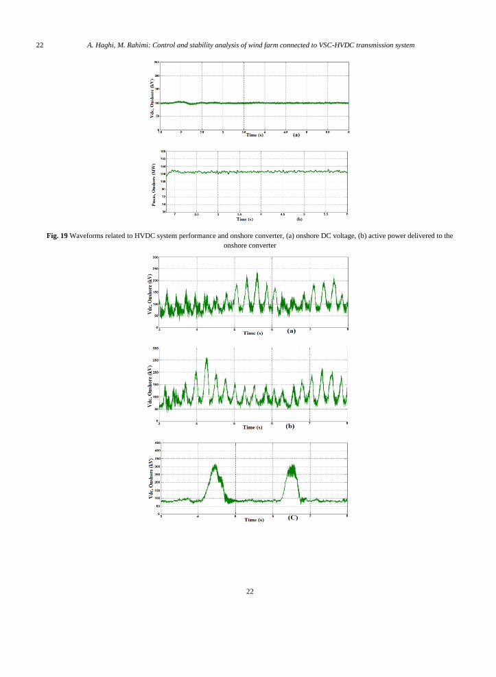
Fig. 19 shows DC-link voltage of the onshore converter Vdc2 and output active power of the onshore converter
injected to the grid. According to Fig. 19(b), 130 MW active power is delivered to the onshore converter, and thus
there is 15 MW power loss in the HVDC transmission line. Considering Fig. 19(a), the DC-link voltage in the

10 A. Haghi, M. Rahimi: Control and stability analysis of wind farm connected to VSC-HVDC transmission system
10
onshore converter is stable and has been set to its reference value. According to Figs. 18 and 19, the system response
is stable and this is in agreement with the modal analysis results.
Figure 20 shows the DC-link voltage of the onshore side for different values of DC-link voltage control
bandwidths and at transmission line length of 150 km. It is clear that for the DC-link bandwidths of 10 Hz and 20
Hz, the system is unstable as mentioned in the modal analysis.
5.2 Effects of onshore grid short circuit power on the DC link voltage dynamics
In the simulation results of Figs. 18-20, the short circuit power (Ssc) of the onshore grid was considered equal to
2000 MVA. In this section, the HVDC line length is considered 100 Km and the DC-link control bandwidth is
selected equal to 50 Hz, and then effect of onshore grid short circuit power (Ssc) on the DC-link stability is
examined. Figure 21 shows the DC-link voltage at the onshore side under four different values of onshore grid short
circuit power, i.e. 2000 MVA, 1000 MVA, 500 MVA and 200 MVA.
As depicted in Fig. 21, by weakening the AC onshore grid, the DC-link dynamics moves toward the unstable
state. According to Fig. 21, at Ssc=500 and 200 MVA, the DC-link voltage response is oscillatory and unstable.
6. Conclusion
This paper deals with the study, modeling and control of VSC-HVDC system connected to offshore wind farms
and addresses some issues regarding the factors affecting the stability of the system under study. In this way,
theoretical and mathematical expressions regarding the control and modeling of the VSC-HVDC connected wind
farm is presented. Then, by the modal and frequency response analysis and time domain simulations, the impacts of
the DC-link control bandwidth, the HVDC line length and the onshore grid short circuit power on the system
stability examined. Consequently, by increasing the HVDC line length and reducing the DC-link voltage bandwidth,
the system modes and responses moved toward the unstable state. Also, at the 150 Km HVDC line length, the
system responses were unstable at DC-link control bandwidths of 10 Hz and 20 Hz. In the case of weak ac onshore
grid, the DC-link dynamics may become unstable. In this paper, the effect of grid short-circuit power on the DC-link
voltage response was studied. It was shown that the response of the under study system is unstable when the short
circuit power of the onshore grid is 500 MVA or less.
Appendix A
Table A1 Parameters related to the system under study shown in Fig. 1
Section Parameter Amount Unit
Wind farms
Number of Wind Farms 2 …
Total Number of Turbines 90 …
Rated Voltage (each turbine) 690 V
Rated Frequency 50 Hz
Onshore Grid
Short Circuit Power 2000 MVA
Base Voltage (rms, line-line) 230 kV
Grid Impedance Angle 80 degree
Phase reactors Inductance 0.0239 H
Resistance 0.0750 Ohm
HVDC System Line to Line dc voltage 200 kV DC
Power Rating 180 MW
HVDC Cable Cable Length 100 km
11
11
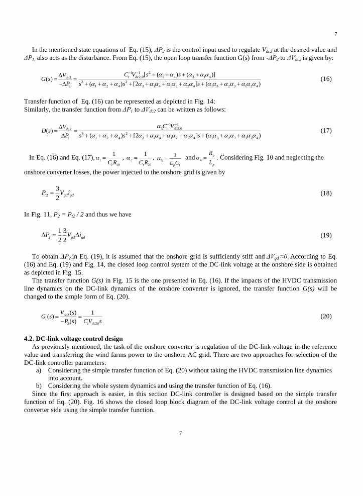
Resistance 3e-2 Ohm/km
Inductance 2e-4 H/km
Capacitance 2.31e-7 F/km
Cdc1, Cdc2 70 μF
PMSG wind
turbine parameters
Rated Voltage 690 V
Rated Frequency 50 Hz
Stator resistance (Rs) 0.0087 pu
dq components of the stator inductances
(Ld and Lq) 0.135 pu
Stator flux linkage due to rotor
permanent magnet pm 0.95 pu
References
[1] Egea-Alvarez, A., Bianchi, F., Junyent-Ferré, A. et al, “Voltage control of multiterminal VSC-HVDC transmission systems for offshore wind
power plants: Design and implementation in a scaled platform”, IEEE Transactions on Industrial Electronics, 60(6), pp. 2381-2391
(2013).
[2] 2017 European Statistics. EWEA Std. [Online]. Available: http://www.ewea.org/Statistics. Accessed 15 February 2018.
[3] The European Offshore Wind Industry–Key Trends and Statistics 2016 (2017) https://windeurope.org/about-
wind/statistics/offshore/european-offshore-wind-industry-key-trends-and-statistics-2016. Accessed 26 January 2017.
[4] Raza, A., Dianguo, X., Xunwen, S. et al, “A Novel Multiterminal VSC-HVdc Transmission Topology for Offshore Wind
Farms”, IEEE Transactions on Industry Applications, 53(2), pp. 1316-1325 (2017).
[5] Haileselassie, T. M. “Control, dynamics and operation of multi-terminal VSC-HVDC transmission systems”, Doctoral thesis, (2012).
[6] Prabhu, N. A., Latha, R., Sankaran, K. et al, “Impact of knowledge management on offshore software development: An exploratory study”, In
Advanced Computing (ICoAC), 2011 Third International Conference on, pp. 121-128, IEEE (2011).
[7] Li, Q. and Wang, H. “Two-stage simulation optimization for optimal development of offshore wind farm under wind uncertainty”, In
Proceedings of the 2016 Winter Simulation Conference, pp. 2891-2902, IEEE Press (2016).
[8] Chodura, P., Gibescu, M., Kling, W.L. et al, “Investigation of the impact of embedded VSC-HVDC active and reactive power control on
power system stability”, In PowerTech, 2015 IEEE Eindhoven, pp. 1-6, IEEE (Jun., 2015).
[9] Erlich, I., Shewarega, F. and Winter, W. “A method for incorporating VSC-HVDC into the overall grid voltage-reactive power control task”,
In Power Systems Computation Conference (PSCC), pp. 1-7, IEEE (Jun., 2016).
[10] Liu, Y. and Chen, Z. “Voltage sensitivity based reactive power control on VSC-HVDC in a wind farm connected hybrid multi-infeed HVDC
system”, In PowerTech (POWERTECH), 2013 IEEE Grenoble, pp. 1-6, IEEE (Jun., 2013).
[11] Wei, C.Z., Mou, M., An, W. et al, “Optimization of reactive power and voltage for hybrid AC/VSC-HVDC system”, 12th IET
International Conference on AC and DC Power Transmission (ACDC 2016) (2016).
[12] Perveen, R., Kishor, N. and Mohanty, S.R. “Off-shore wind farm development: Present status and challenges”, Renewable and
Sustainable Energy Reviews, 29, pp. 780-792 (2014).
[13] Bahrman, M.P. and Johnson, B.K. “The ABCs of HVDC transmission technologies”, IEEE power and energy magazine, 5(2), pp. 32-
44 (2007).
[14] Müller, H.K., Torbaghan, S.S., Gibescu, M. et al, “The need for a common standard for voltage levels of HVDC VSC technology”, Energy
Policy, 63, pp. 244-251 (2013).
[15] Muyeen, S.M., Takahashi, R. and Tamura, J. “Operation and control of HVDC-connected offshore wind farm”, IEEE Transactions on
Sustainable Energy, 1(1), pp. 30-37 (2010).
[16] Kunjumuhammed, L.P., Pal, B.C., Gupta, R. et al, “Stability analysis of a PMSG-based large offshore wind farm connected to a VSC-
HVDC”, IEEE Transactions on Energy Conversion, 32(3), pp.1166-1176 (2017).
[17] Li, Y., Xu, Z., Østergaard, J. and Hill, D.J. “Coordinated control strategies for offshore wind farm integration via VSC-HVDC for system
frequency support”, IEEE Transactions on Energy Conversion, 32(3), pp. 843-856 (2017).
[18] Mitra, P., Zhang, L. and Harnefors, L. “Offshore wind integration to a weak grid by VSC-HVDC links using power-synchronization control:
A case study”, IEEE Transactions on Power Delivery, 29(1), pp.453-461 (2014).

12 A. Haghi, M. Rahimi: Control and stability analysis of wind farm connected to VSC-HVDC transmission system
12
[19] Moawwad, A., El Moursi, M.S. and Xiao, W. “Advanced fault ride-through management scheme for VSC-HVDC connecting offshore wind
farms”, IEEE Transactions on Power Systems, 31(6), pp. 4923-4934 (2016).
[20] Daoud, M.I., Massoud, A.M., Abdel-Khalik, A.S. et al, “A flywheel energy storage system for fault ride through support of grid-connected
VSC HVDC-based offshore wind farms”, IEEE Transactions on Power Systems, 31(3), pp.1671-1680 (2016).
[21] De Boeck, S., Tielens, P., Leterme, W. et al, “Configurations and earthing of HVDC grids”, In Power and Energy Society General Meeting
(PES), pp. 1-5 (Jul., 2013).
[22] Pinto, R.T. and La Seta, P. “Dynamics and Control of VSC-based HVDC Systems: A practical approach to modeling and simulation. LAP
Lambert Academic Publishing”, (2012).
[23] Vrana, T.K. and Energi, S. “Review of HVDC component ratings: XLPE cables and VSC converters”, In Energy Conference
(ENERGYCON), 2016 IEEE International, pp. 1-6 (Apr., 2016).
[24] Xu, L. and Andersen, B.R. “Grid connection of large offshore wind farms using HVDC”, Wind Energy, 9(4), pp. 371-382 (2006).
[25] Xiang, D., Ran, L., Bumby, J.R. et al, “Coordinated control of an HVDC link and doubly fed induction generators in a large offshore wind
farm”, IEEE transactions on power delivery, 21(1), pp.463-471 (2006).
[26] Olguin, R.E.T. “Grid integration of offshore wind farms using hybrid hvdc transmission: Control and operational characteristics”, Doctoral
thesis (2013).
[27] Chinchilla, M., Arnaltes, S. and Burgos, J.C. “Control of permanent-magnet generators applied to variable-speed wind-energy systems
connected to the grid”, IEEE Transactions on energy conversion, 21(1), pp.130-135 (2006).
Ali Haghi received the B.Sc. and M.Sc. degrees from University of Kashan, Kashan, Iran, both in electrical
engineering in 2013 and 2017, respectively. His current research interests include modeling and control of power
system dynamics, power electronics and its applications in power systems and renewable energy systems.
Mohsen Rahimi received his B.Sc. degree in electrical engineering in 2001 from Isfahan University of Technology,
Isfhan, Iran. He obtained both his M.Sc. and Ph.D. degrees in Electrical Engineering from Sharif University of
Technology (SUT), Tehran, Iran, in 2003 and 2011, respectively. He joined the Department of Electrical and
Computer Engineering at University of Kashan, Kashan, Iran, as an Assistant Professor, in 2011. Currently, he is an
Associate Professor at University of Kashan, and his major research interests include modeling and control of
renewable energy sources, wind turbines and microgrids.

13
13
Figures captions:
Fig. 1 Under study system Layout
Fig. 2 General block diagram of the AC voltage control by offshore converter
Fig. 3 Wind farms connected to the offshore AC grid
Fig. 4 Inner current control loop of offshore converter, (a) d-axis, (b) q-axis
Fig. 5 Outer voltage control loops of the offshore converter, (a) d-axis, (b) q-axis
Fig. 6 Overall control block diagram of the offshore converter
Fig. 7 Onshore converter circuit model connected to the onshore AC grid
Fig. 8 Inner current control loops of the onshore converter, (a) d-axis, (b) q-axis
Fig. 9 Overall block diagram of the onshore converter control
Fig. 10 Symmetric monopole VSC-HVDC system with detailed DC-transmission link
Fig. 11 Asymmetric equivalent model of the VSC-HVDC system given in Fig. 10
Fig. 12 Simplified equivalent model of the VSC-HVDC system
Fig. 13 Small signal model of the VSC-HVDC system
Fig. 14 Open loop transfer function of the VSC-HVDC system
Fig. 15 Closed loop control system of the DC-link voltage
Fig. 16 Simplified block diagram of the DC-link voltage control by the onshore side converter
Fig. 17 Bode diagram of the under study system with 150 km line length for two different DC-link control bandwidths, (a) 10 Hz, (b) 20 Hz
Fig. 18 Waveforms related to HVDC system performance and offshore converter, (a) offshore converter output
active power, (b) reactive power exchanged between the converter and offshore AC grid, (c) DC-link voltage of
offshore converter compared to the neutral point
14 A. Haghi, M. Rahimi: Control and stability analysis of wind farm connected to VSC-HVDC transmission system
14
Fig. 19 Waveforms related to HVDC system performance and onshore converter, (a) onshore DC voltage, (b) active
power delivered to the onshore converter
Fig. 20 Effects of controller coefficients variations with bandwidth changes on the DC-link voltage, (a) 10 Hz, (b)
20 Hz, (c) 30 Hz, (d) 40 Hz, (e) 50 Hz
Fig. 21 Effects of onshore grid short circuit power (Ssc) on DC-link voltage response, (a) 2000 MVA, (b) 1000
MVA, (c) 500 MVA, (d) 200 MVA
Tables captions:
Table 1 Modal analysis for different DC-link controller bandwidth and HVDC transmission line lengths

15
15
Figures and Tables:
Pc
A B C
A B C
Wind Farm 1
Wind Farm 2
20 kV 100 kV
Medium
Voltage
Collector
Phase
ReactorPwF Pcg
±100 kV, 150 km
HVDC Cable
Offshore
Converter
Onshore
Converter
Phase
Reactor
AC filters
40 Mvar
AC filters
40 Mvar
100 kV230 kV
230 kV, 50 Hz
2000 MVA
equivalent
Onshore Grid
Phi=80 (deg) at
1st & 3
rd harm.
Three- phase
Parallel RL Branch
AC System
Fig. 1 Under study system Layout
16 A. Haghi, M. Rahimi: Control and stability analysis of wind farm connected to VSC-HVDC transmission system
16
Fig. 2 General block diagram of the AC voltage control by offshore converter
Fig. 3 Wind farms connected to the offshore AC grid
Fig. 4 Inner current control loop of offshore converter, (a) d-axis, (b) q-axis

17
17
Fig. 5 Outer voltage control loops of the offshore converter, (a) d-axis, (b) q-axis
Fig. 6 Overall control block diagram of the offshore converter
Fig. 7 Onshore converter circuit model connected to the onshore AC grid
18 A. Haghi, M. Rahimi: Control and stability analysis of wind farm connected to VSC-HVDC transmission system
18
Fig. 8 Inner current control loops of the onshore converter, (a) d-axis, (b) q-axis
Fig. 9 Overall block diagram of the onshore converter control
Fig. 10 Symmetric monopole VSC-HVDC system with detailed DC-transmission link

19
19
Fig. 11 Asymmetric equivalent model of the VSC-HVDC system given in Fig. 10
Fig. 12 Simplified equivalent model of the VSC-HVDC system
Fig. 13 Small signal model of the VSC-HVDC system
Fig. 14 Open loop transfer function of the VSC-HVDC system

20 A. Haghi, M. Rahimi: Control and stability analysis of wind farm connected to VSC-HVDC transmission system
20
Fig. 15 Closed loop control system of the DC-link voltage
Fig. 16 Simplified block diagram of the DC-link voltage control by the onshore side converter
(a)
(b)
Fig. 17 Bode diagram of the under study system with 150 km line length for two different DC-link control bandwidths, (a) 10 Hz, (b) 20 Hz

21
21
Fig. 18 Waveforms related to HVDC system performance and offshore converter, (a) offshore converter output active power, (b) reactive power
exchanged between the converter and offshore AC grid, (c) DC-link voltage of offshore converter compared to the neutral point
22 A. Haghi, M. Rahimi: Control and stability analysis of wind farm connected to VSC-HVDC transmission system
22
Fig. 19 Waveforms related to HVDC system performance and onshore converter, (a) onshore DC voltage, (b) active power delivered to the
onshore converter

23
23
Fig. 20 Effects of controller coefficients variations with bandwidth changes on the DC-link voltage, (a) 10 Hz, (b) 20 Hz, (c) 30 Hz, (d) 40 Hz, (e)
50 Hz
Fig. 21 Effects of onshore grid short circuit power (Ssc) on DC-link voltage response, (a) 2000 MVA, (b) 1000 MVA, (c) 500 MVA, (d) 200
MVA

24 A. Haghi, M. Rahimi: Control and stability analysis of wind farm connected to VSC-HVDC transmission system
24
Table 1. Modal analysis for different DC-link controller bandwidth and HVDC transmission line lengths
Bandwidth Line length eigenvalues (100×) PM (deg) GM (db) Stability
10 Hz
100 km
-0.0995 ± 3.4738i;
-0.0039 ± 0.0013i;
-1.2566
89.4 88.4 Stable
150 km
-0.1002 ± 2.7489i;
0.0005 ± 0.0041i;
-1.2566
-0.334 4.05 Unstable
20 Hz
100 km
-0.0995 ± 3.4738i;
-0.0039 ± 0.0072i;
-2.5132
83.6 84.5 Stable
150 km
-0.1002 ± 2.7489i;
0.0005 ± 0.0083i;
-2.5132
0.0175 -1.75 Unstable
30 Hz
100 km
-0.0995 + 3.4738i; -0.0995 - 3.4738i
-0.0039 + 0.0116i; -0.0039 - 0.0116i
-3.7698
53.6 75.9 Stable
150 km
-0.1001 + 2.8222i; -0.1001 - 2.8222i
-0.0001 + 0.0124i; -0.0001 - 0.0124i
-3.7698
0.335 73.1 Stable
40 Hz
100 km
-0.0995 ± 3.4739i;
-0.0039 ± 0.0158i;
-5.0264
39.8 70.1 Stable
150 km
-0.1001 ± 2.8222i;
-0.0002 ± 0.0166i;
-5.0264
0.598 67.6 Stable

25
25
50 Hz
100 km
-0.0995 ± 3.4739i;
-0.0039 ± 0.0200i;
-6.2830
31.9 65.9 Stable
150 km
-0.1001 ± 2.8222i;
-0.0003 ± 0.0207i;
-6.2830
0.832 63.4 Stable