Embed Size (px)
Citation preview

Control and Control and Monitoring of Monitoring of Front-end and Front-end and
Readout Readout Electronics in Electronics in
ALICEALICEPeter ChochulaPeter Chochula
Peter Chochula – ALICE DCS DCS Workshop – March 2004, Geneva
OutlineOutline Front-End and ReadOut electronics (FERO) Front-End and ReadOut electronics (FERO)
access strategy will be described using SPD access strategy will be described using SPD as an exampleas an example
Live demonstration of a prototype solutionLive demonstration of a prototype solution Discussion of related problemsDiscussion of related problems
This is not a first presentation on FERO This is not a first presentation on FERO problematics. Proposed solution should problematics. Proposed solution should
now be adopted as ALICE standard – your now be adopted as ALICE standard – your feedback is therefore essential.feedback is therefore essential.
Peter Chochula – ALICE DCS DCS Workshop – March 2004, Geneva
Basic Interaction Between Basic Interaction Between FERO and DCSFERO and DCS
FERO controls ranges from downloading of FERO controls ranges from downloading of parameters to high-level tasks such as parameters to high-level tasks such as calibrationcalibration
Monitoring includes direct reading of Monitoring includes direct reading of parameters provided by the electronics or parameters provided by the electronics or indirect surveillance using associated indirect surveillance using associated equipment (power supplies etc.)equipment (power supplies etc.)
Corrective actions are expected from the Corrective actions are expected from the control system in case of anomalous values control system in case of anomalous values (errors, excessive readings etc.)(errors, excessive readings etc.)
Peter Chochula – ALICE DCS DCS Workshop – March 2004, Geneva
The Front-end Device The Front-end Device (FED)(FED)
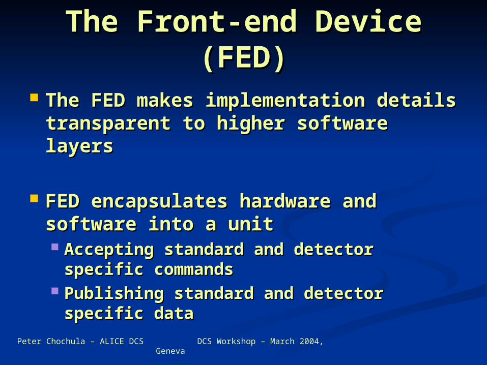
The FED makes implementation The FED makes implementation details transparent to higher details transparent to higher software layerssoftware layers
FED encapsulates hardware and FED encapsulates hardware and software into a unitsoftware into a unit Accepting standard and detector Accepting standard and detector
specific commandsspecific commands Publishing standard and detector Publishing standard and detector
specific dataspecific data
Peter Chochula – ALICE DCS DCS Workshop – March 2004, Geneva
FERO
• FERO configuration is implemented via DDLFERO configuration is implemented via DDL• Monitoring is based on different technologiesMonitoring is based on different technologies
DDL
Configuration Monitoring
Class A
Configuration Monitoring
FERO
• FERO configuration can be performed via FERO configuration can be performed via DDL and optionally using alternative techno-DDL and optionally using alternative techno-logy (Profibus, Ethernet, etc.)logy (Profibus, Ethernet, etc.)
DDL
Class B
Non-DDLtechnology
FERO Control and FERO Control and Monitoring Strategies in Monitoring Strategies in
ALICEALICE
Configuration Monitoring
FERO
• alternative technology such as Profibus, alternative technology such as Profibus, Ethernet, Easynet etc. is used to configure Ethernet, Easynet etc. is used to configure FEROFERO
Class C
Non-DDLtechnology
Configuration Monitoring
FERO
• Configuration and Monitoring are sharing Configuration and Monitoring are sharing the same access path to FEROthe same access path to FERO
Class D
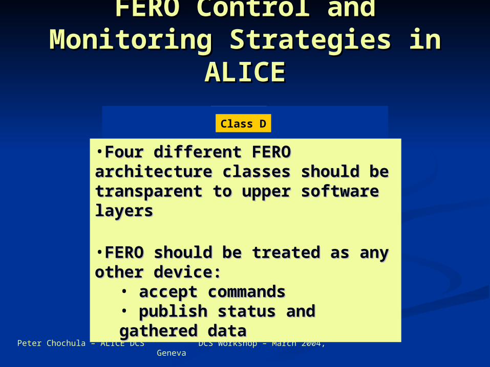
•Four different FERO Four different FERO architecture classes should be architecture classes should be transparent to upper software transparent to upper software layerslayers
•FERO should be treated as any FERO should be treated as any other device:other device:
• accept commandsaccept commands• publish status and gathered publish status and gathered datadata
Peter Chochula – ALICE DCS DCS Workshop – March 2004, Geneva
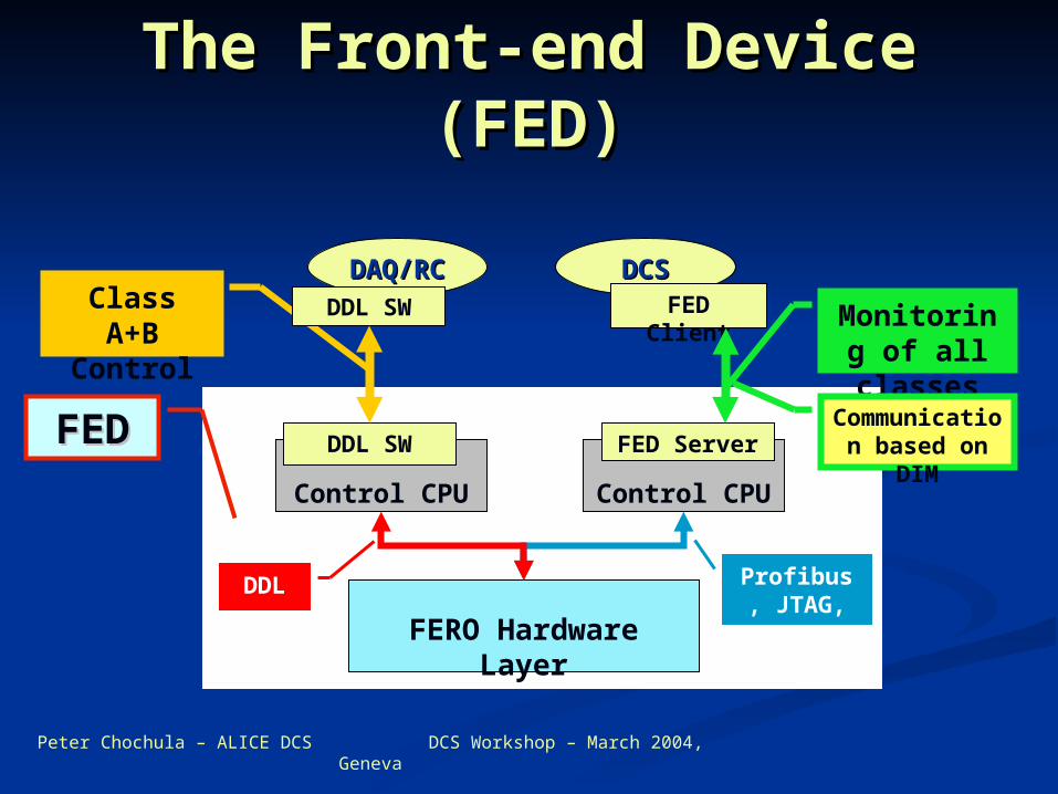
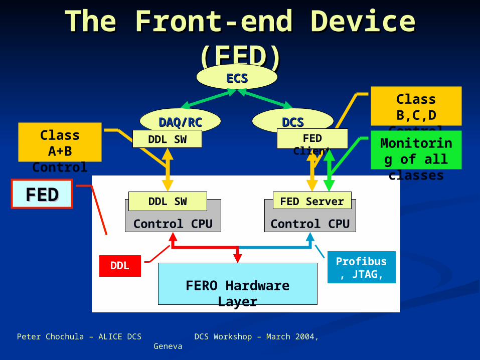
Class A+B Control
The Front-end Device The Front-end Device (FED)(FED)
DAQ/RCDAQ/RC DCSDCS
Control CPU
FERO Hardware Layer
FED Server
FED Client
Profibus, JTAG, etc.
Control CPU
DDL SW
DDL SW
FEDFED
DDL
Monitoring of all classes
Communication based on DIM
Peter Chochula – ALICE DCS DCS Workshop – March 2004, Geneva
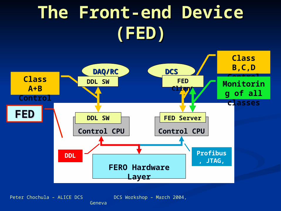
Class B,C,D Control
Class A+B Control
The Front-end Device The Front-end Device (FED)(FED)
DAQ/RCDAQ/RC DCSDCS
Control CPU
FERO Hardware Layer
FED Server
FED Client
Profibus, JTAG, etc.
Control CPU
DDL SW
DDL SW
FEDFED
DDL
Monitoring of all classes
Peter Chochula – ALICE DCS DCS Workshop – March 2004, Geneva
Class B,C,D Control
Class A+B Control
The Front-end Device The Front-end Device (FED)(FED)
ECSECS
DAQ/RCDAQ/RC DCSDCS
Control CPU
FERO Hardware Layer
FED Server
FED Client
Profibus, JTAG, etc.
Control CPU
DDL SW
DDL SW
FEDFED
DDL
Monitoring of all classes
Peter Chochula – ALICE DCS DCS Workshop – March 2004, Geneva
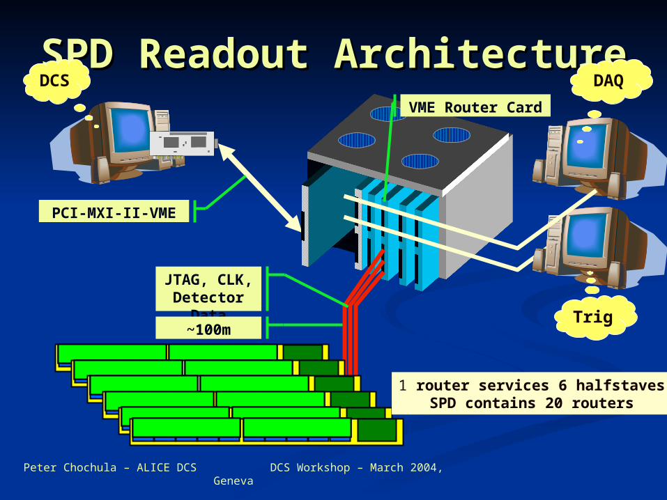
SPD Readout SPD Readout ArchitectureArchitectureDC
S
Trig
DAQ
JTAG, CLK, Detector Data
~100m
PCI-MXI-II-VME
VME Router Card
1 router services 6 halfstavesSPD contains 20 routers
Peter Chochula – ALICE DCS DCS Workshop – March 2004, Geneva
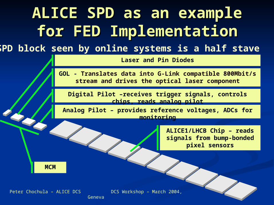
ALICE SPD as an example ALICE SPD as an example for FED Implementationfor FED Implementation
Basic SPD block seen by online systems is a half staveLaser and Pin Diodes
GOL - Translates data into G-Link compatible 800Mbit/s stream and drives the optical laser component
Digital Pilot –receives trigger signals, controls chips, reads analog pilot
Analog Pilot – provides reference voltages, ADCs for monitoring
ALICE1/LHCB Chip – reads signals from bump-bonded pixel sensors
MCM
Peter Chochula – ALICE DCS DCS Workshop – March 2004, Geneva
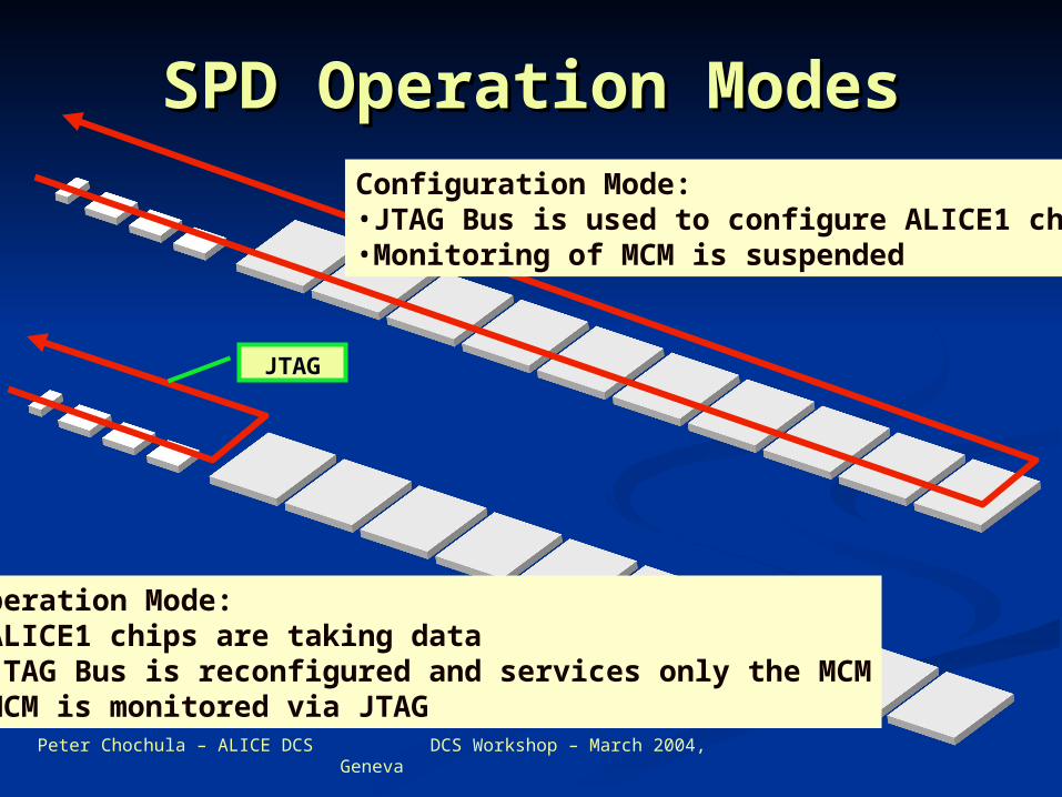
SPD Operation ModesSPD Operation ModesConfiguration Mode:•JTAG Bus is used to configure ALICE1 chips•Monitoring of MCM is suspended
Operation Mode:•ALICE1 chips are taking data•JTAG Bus is reconfigured and services only the MCM•MCM is monitored via JTAG
JTAG
Peter Chochula – ALICE DCS DCS Workshop – March 2004, Geneva
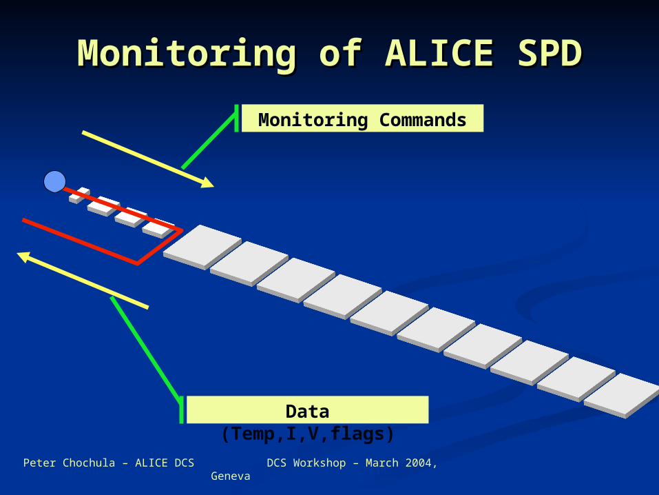
Monitoring of ALICE SPDMonitoring of ALICE SPD
Monitoring Commands
Data (Temp,I,V,flags)
Peter Chochula – ALICE DCS DCS Workshop – March 2004, Geneva
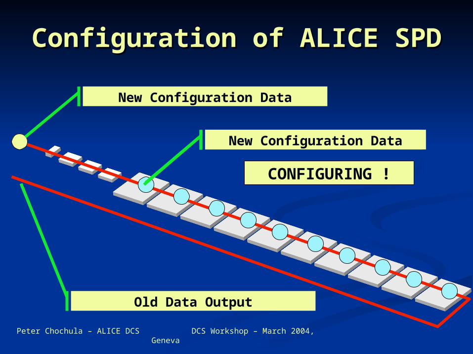
Configuration of ALICE SPDConfiguration of ALICE SPD
New Configuration Data
Current Configuration Data
CONFIGURING !
New Configuration Data
Old Data Output
Peter Chochula – ALICE DCS DCS Workshop – March 2004, Geneva
Implementation of SPD Implementation of SPD FERO ControlFERO Control
Application called “SPD FED Server Application called “SPD FED Server “ written in C++ (WXP)“ written in C++ (WXP)
Various tasks implemented as Various tasks implemented as threadsthreads ConfigurationConfiguration MonitoringMonitoring Readout tests, etc…Readout tests, etc…
Operation of threads is synchronized Operation of threads is synchronized by the main applicationby the main application
The threads are called AGENTS The threads are called AGENTS

Peter Chochula – ALICE DCS DCS Workshop – March 2004, Geneva
SPD AgentsSPD Agents
Monitoring Agent(MA)
Control Agent(CA)
Monitoring Agent continuously reads the MCM parameters
During the execution of control task the operation of MA must be suspended
The MA is allowed to resume its operation
SPD FED SERVER
Peter Chochula – ALICE DCS DCS Workshop – March 2004, Geneva
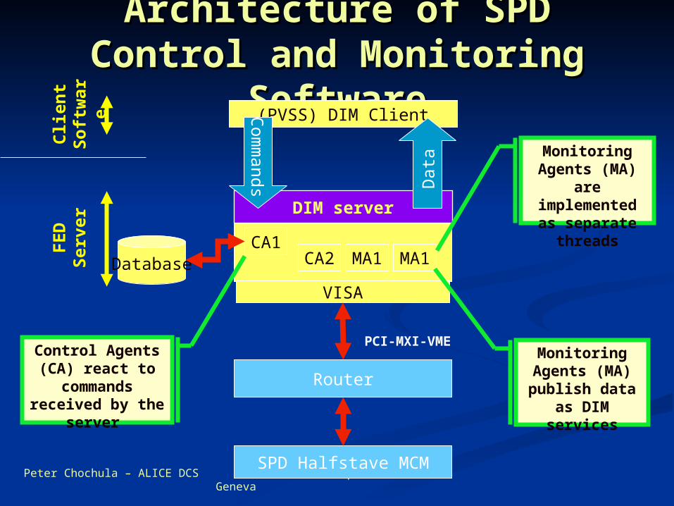
Architecture of SPD Control Architecture of SPD Control and Monitoring Softwareand Monitoring Software
(PVSS) DIM Client
CA1CA2 MA1 MA1
SPD Halfstave MCM
Router
VISA
PCI-MXI-VME
Database
DIM server
Dat
a Monitoring Agents (MA) are implemented as separate threads
Control Agents (CA) react to commands
received by the server
Monitoring Agents (MA)
publish data as DIM services
FE
DSe
rver
Cli
ent
Soft
war
e
Com
mands
Peter Chochula – ALICE DCS DCS Workshop – March 2004, Geneva
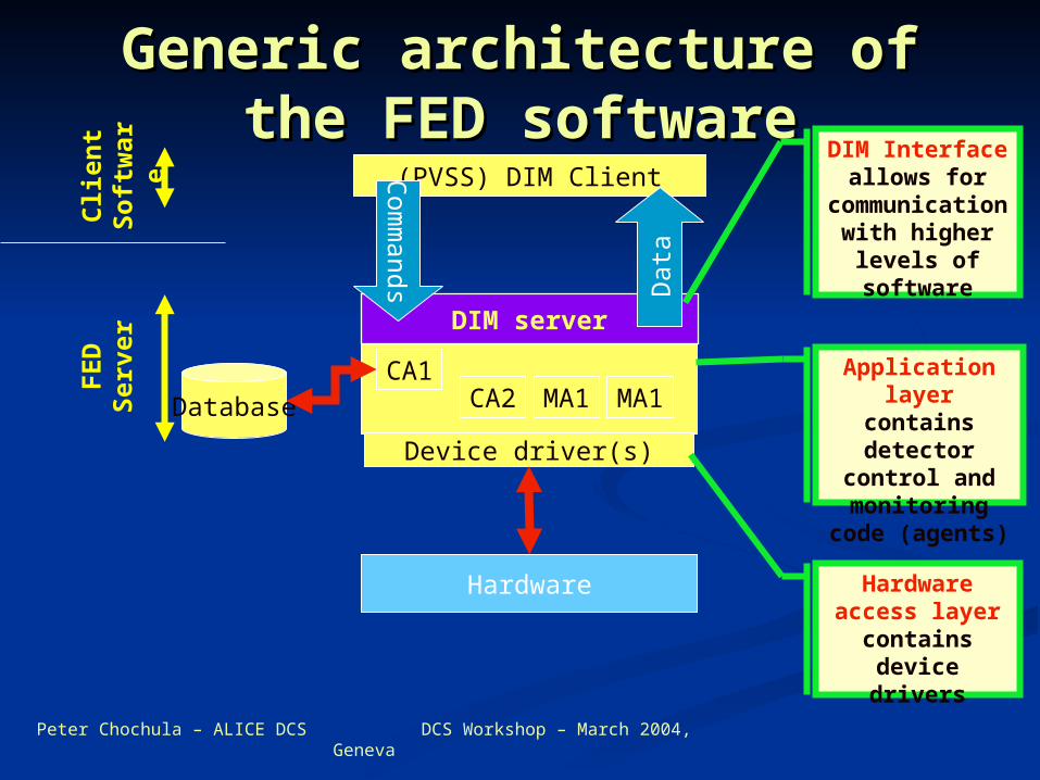
Generic architecture of the Generic architecture of the FED softwareFED software
(PVSS) DIM Client
CA1CA2 MA1 MA1
Hardware
Device driver(s)
Database
DIM server
Dat
a
DIM Interface allows for
communication with higher levels
of software
Hardware access layer contains device drivers
FE
DSe
rver
Cli
ent
Soft
war
e
Com
mands
Application layer contains detector
control and monitoring code
(agents)
Peter Chochula – ALICE DCS DCS Workshop – March 2004, Geneva
SPD FED ServerSPD FED Server SPD FED Server is one and only access SPD FED Server is one and only access
point to the hardware point to the hardware
FED server accepts commands and executes FED server accepts commands and executes themthem It arbitrates access to the hardwareIt arbitrates access to the hardware Synchronizes internal execution of agentsSynchronizes internal execution of agents
Main (DCS) role of the server is monitoring Main (DCS) role of the server is monitoring of sensitive detector parametersof sensitive detector parameters Acquired data is published as serviceAcquired data is published as service

Peter Chochula – ALICE DCS DCS Workshop – March 2004, Geneva
FED Server commands and FED Server commands and servicesservices
The communication can be divided The communication can be divided into standard and sub-detector into standard and sub-detector specific parts.specific parts.
Standard commands include setup Standard commands include setup and monitoring of the FED servers and monitoring of the FED servers itself, initialization and actions itself, initialization and actions common for all architecturescommon for all architectures
SPD specific part includes SPD specific part includes procedures used only by SPDprocedures used only by SPD

Peter Chochula – ALICE DCS DCS Workshop – March 2004, Geneva
DIM Interface of the SPD DIM Interface of the SPD C/M ServerC/M Server
Recognized commandsRecognized commands
General:General: InitializeInitialize Re-initializeRe-initialize CalibrateCalibrate Modify Running parametersModify Running parameters Publish Active SettingsPublish Active Settings
SPD SpecificSPD Specific Test ReadoutTest Readout Test JTAGTest JTAG Test SEUTest SEU Start/Stop AgentsStart/Stop Agents
Published servicesPublished services
General:General: Server StatusServer Status Agent StatusAgent Status MessagesMessages
Detector data:Detector data: TempTemp I, VI, V Status and error Status and error
flagsflags
Peter Chochula – ALICE DCS DCS Workshop – March 2004, Geneva
FED Server operationFED Server operation
The server needs to be first configured The server needs to be first configured (there are standard built-in settings). (there are standard built-in settings). This includes:This includes: Setting of logging methodSetting of logging method Setting of readout frequencies for the agentsSetting of readout frequencies for the agents Setting of deadbands for the agentsSetting of deadbands for the agents
On request the agents start their On request the agents start their operation. States of individual agents operation. States of individual agents are visible to all server components and are visible to all server components and are used for internal synchronizationare used for internal synchronization
Monitoring agents typically read data in Monitoring agents typically read data in predefined intervals (auto-triggering). predefined intervals (auto-triggering). External triggers are possibleExternal triggers are possible
Peter Chochula – ALICE DCS DCS Workshop – March 2004, Geneva
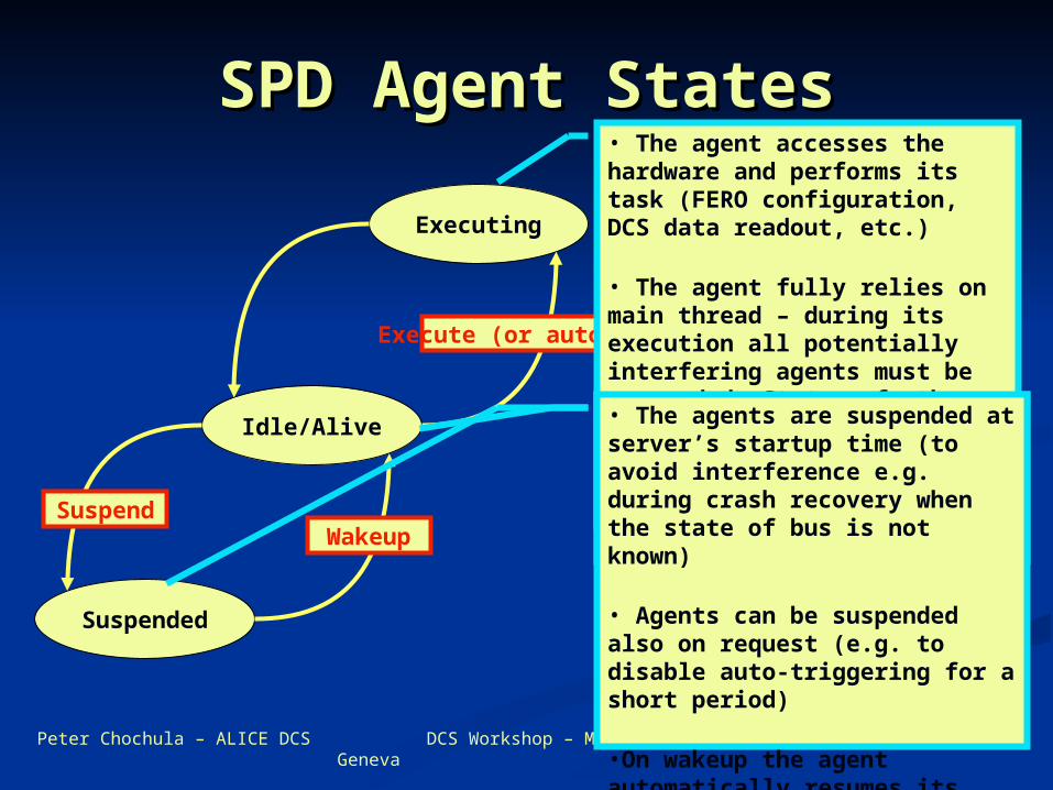
SPD Agent StatesSPD Agent States
Idle/Alive
Executing
Suspended
SuspendWakeup
Execute (or auto-trigger)
• The agent is ready and waits for command or auto-trigger
•Idle agent sends heartbeat to the main thread
• The agent accesses the hardware and performs its task (FERO configuration, DCS data readout, etc.)
• The agent fully relies on main thread – during its execution all potentially interfering agents must be suspended. Status of other threads is signaled to individual agents.
• Execution of complex agents can be interrupted by external command (e.g. calibration run can be stopped and FERO can be reloaded)
• The agents are suspended at server’s startup time (to avoid interference e.g. during crash recovery when the state of bus is not known)
• Agents can be suspended also on request (e.g. to disable auto-triggering for a short period)
•On wakeup the agent automatically resumes its previous task
Live Live demonstrationdemonstration

Peter Chochula – ALICE DCS DCS Workshop – March 2004, Geneva
FED Server Setup FED Server Setup Debugging Level
Control
Server Operation Parameters
Debugging Output Control
Internal Agent Status Monitoring
Settings
The Server Setup Panel allows tuning of server operation and debugging• sets monitoring limits and refresh rates• controls complexity of published messages• controls publishing of debugging informatio

Peter Chochula – ALICE DCS DCS Workshop – March 2004, Geneva
FED Server ControlFED Server Control
Agent Status Info:•Suspended•Executing•Idle
Server Status Info:•Operational•Initializing•Calibrating•Checking JTAG•…..
Server Commands
The Server Control Panel allows sending commands to the FED
On receipt of command C/M Server:•Suspends monitoring agents (if needed)•Performs requested task•Resumes agent operation
Peter Chochula – ALICE DCS DCS Workshop – March 2004, Geneva
Messenger Service and Messenger Service and Message ViewerMessage Viewer
Detector
Caller
Mesage Severity
Time & Date
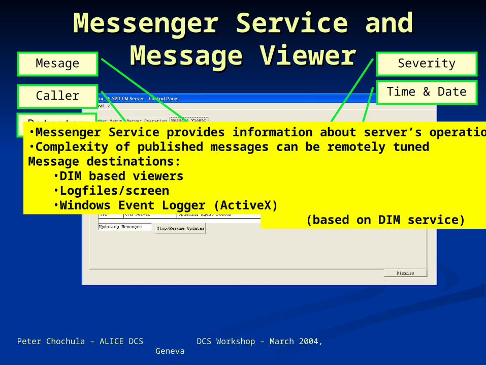
Example of PVSSII Message Viewer (based on DIM service)
•Messenger Service provides information about server’s operation•Complexity of published messages can be remotely tunedMessage destinations:
•DIM based viewers•Logfiles/screen•Windows Event Logger (ActiveX)
Peter Chochula – ALICE DCS DCS Workshop – March 2004, Geneva
Detector Data SubscriberDetector Data Subscriber
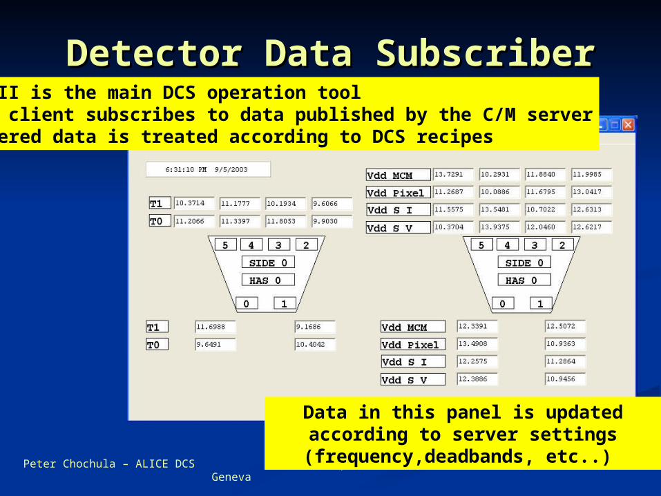
Data in this panel is updated according to server settings (frequency,deadbands, etc..)
PVSSII is the main DCS operation toolPVSS client subscribes to data published by the C/M serverGathered data is treated according to DCS recipes
Peter Chochula – ALICE DCS DCS Workshop – March 2004, Geneva
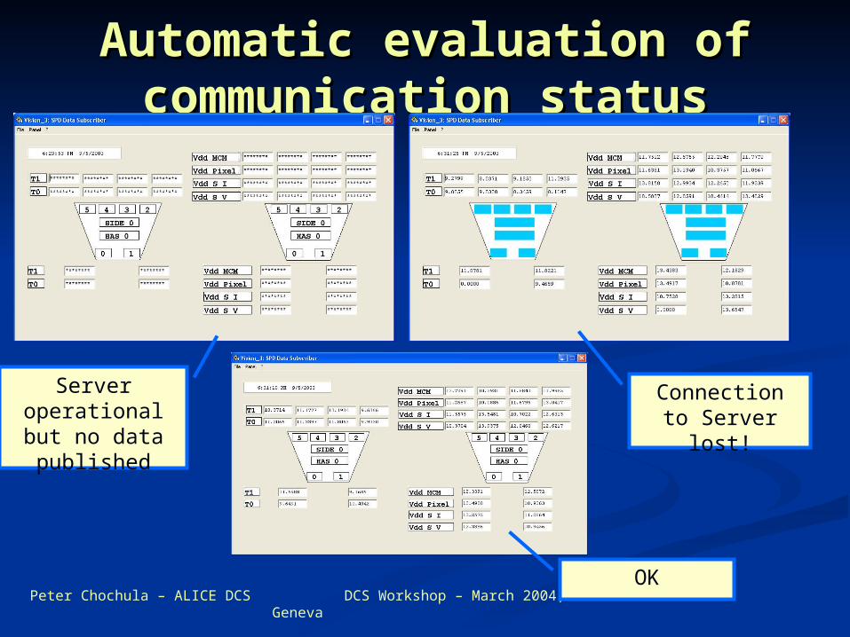
Automatic evaluation of Automatic evaluation of communication statuscommunication status
Server operational but no data published
Connection to Server lost!
OK
End of End of demonstrationdemonstration
Peter Chochula – ALICE DCS DCS Workshop – March 2004, Geneva
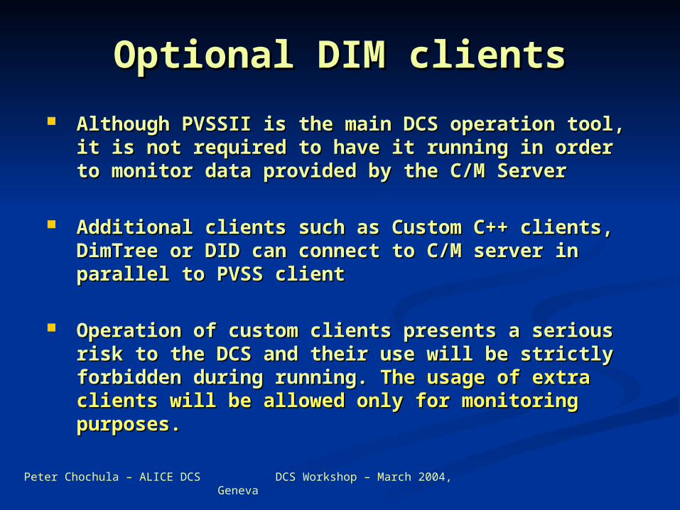
Optional DIM clientsOptional DIM clients
Although PVSSII is the main DCS operation tool, Although PVSSII is the main DCS operation tool, it is not required to have it running in order to it is not required to have it running in order to monitor data provided by the C/M Servermonitor data provided by the C/M Server
Additional clients such as Custom C++ clients, Additional clients such as Custom C++ clients, DimTree or DID can connect to C/M server in DimTree or DID can connect to C/M server in parallel to PVSS clientparallel to PVSS client
Operation of custom clients presents a serious Operation of custom clients presents a serious risk to the DCS and their use will be strictly risk to the DCS and their use will be strictly forbidden during running. forbidden during running. The usage of extra The usage of extra clients will be allowed only for monitoring clients will be allowed only for monitoring purposes.purposes.
Live Live demonstration of demonstration of
optional DIM optional DIM clientsclients
Peter Chochula – ALICE DCS DCS Workshop – March 2004, Geneva
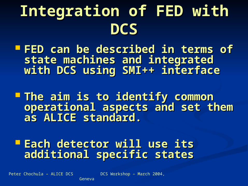
Integration of FED with Integration of FED with DCSDCS
FED can be described in terms of FED can be described in terms of state machines and integrated state machines and integrated with DCS using SMI++ interfacewith DCS using SMI++ interface
The aim is to identify common The aim is to identify common operational aspects and set them operational aspects and set them as ALICE standard.as ALICE standard.
Each detector will use its Each detector will use its additional specific statesadditional specific states
Peter Chochula – ALICE DCS DCS Workshop – March 2004, Geneva
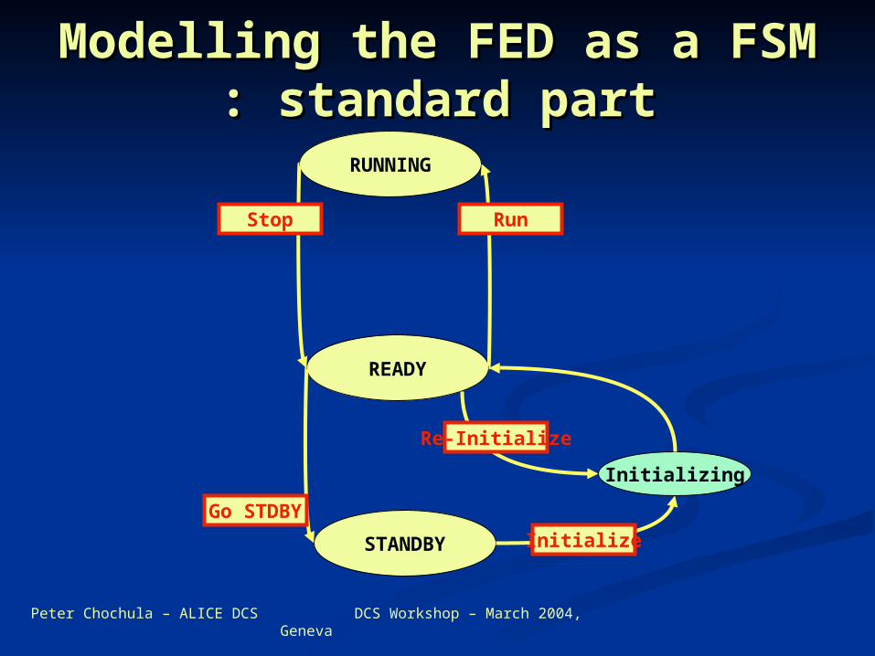
Modelling the FED as a Modelling the FED as a FSM : standard partFSM : standard part
READY
RUNNING
STANDBY
Go STDBY
Initialize
Initializing
Re-Initialize
RunStop
Peter Chochula – ALICE DCS DCS Workshop – March 2004, Geneva
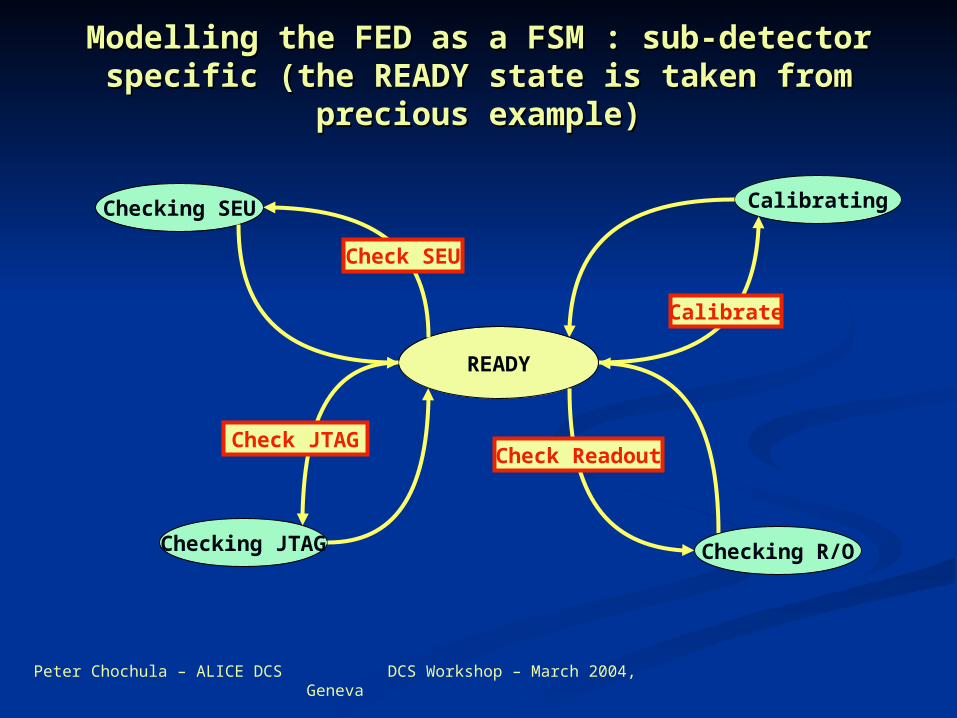
Modelling the FED as a FSM : sub-detector Modelling the FED as a FSM : sub-detector specific (the READY state is taken from specific (the READY state is taken from
precious example)precious example)
Calibrating
READY
Checking SEU
Checking JTAG Checking R/O
Check SEU
Check JTAG
Calibrate
Check Readout
Peter Chochula – ALICE DCS DCS Workshop – March 2004, Geneva
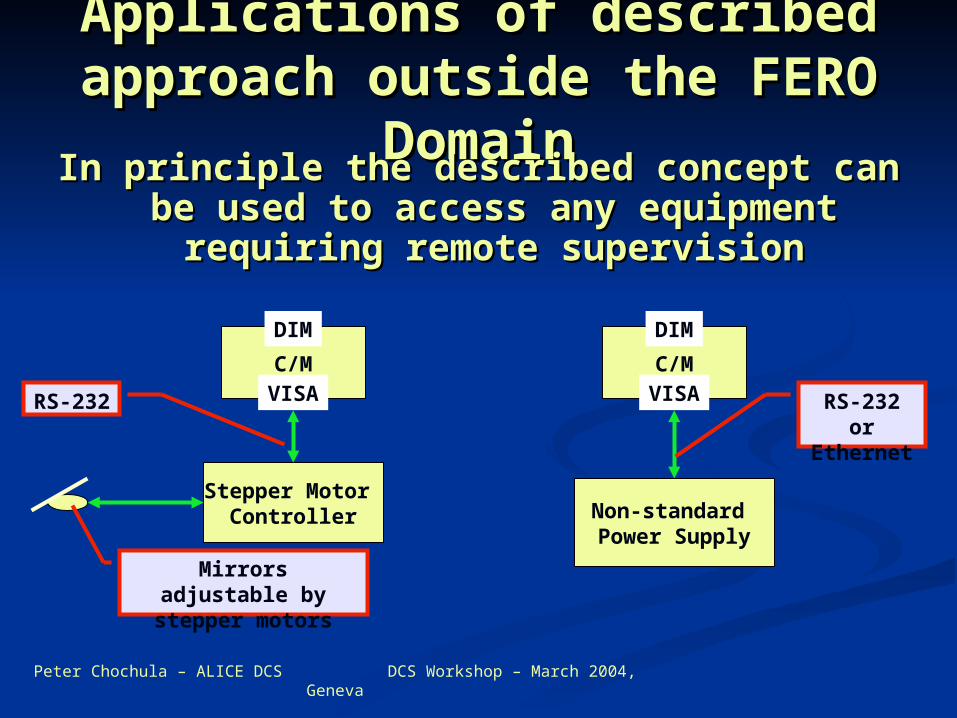
Applications of described Applications of described approach outside the FERO approach outside the FERO
DomainDomainIn principle the described concept can In principle the described concept can
be used to access any equipment be used to access any equipment requiring remote supervisionrequiring remote supervision
C/M
DIM
VISA
Stepper Motor Controller
C/M
DIM
VISARS-232
Non-standard Power Supply
RS-232 or Ethernet
Mirrors adjustable by stepper motors
Peter Chochula – ALICE DCS DCS Workshop – March 2004, Geneva
Partial ConclusionsPartial Conclusions
Described model allows for monitoring Described model allows for monitoring and control of non-standard devices in and control of non-standard devices in ALICE – not only FEROALICE – not only FERO
The FERO is treated as a device. The The FERO is treated as a device. The developed software makes all hardware developed software makes all hardware details transparent to higher software details transparent to higher software layerslayers
We need your feedback in order to be We need your feedback in order to be able to standardize the commandsable to standardize the commands
Peter Chochula – ALICE DCS DCS Workshop – March 2004, Geneva
A working FED server is A working FED server is just the beginning of the just the beginning of the
story…story… Implementation of FERO software is a Implementation of FERO software is a
very complicated task requiring a lot of very complicated task requiring a lot of expertise – however it is still the easier expertise – however it is still the easier partpart
Tuning of the software will require Tuning of the software will require much more time and experiencemuch more time and experience
DCS team is happy to discuss and help DCS team is happy to discuss and help at least to transfer the knowledge at least to transfer the knowledge between different groups. (Maybe between different groups. (Maybe someone already solved a problem someone already solved a problem which you are dealing with…)which you are dealing with…)
Peter Chochula – ALICE DCS DCS Workshop – March 2004, Geneva
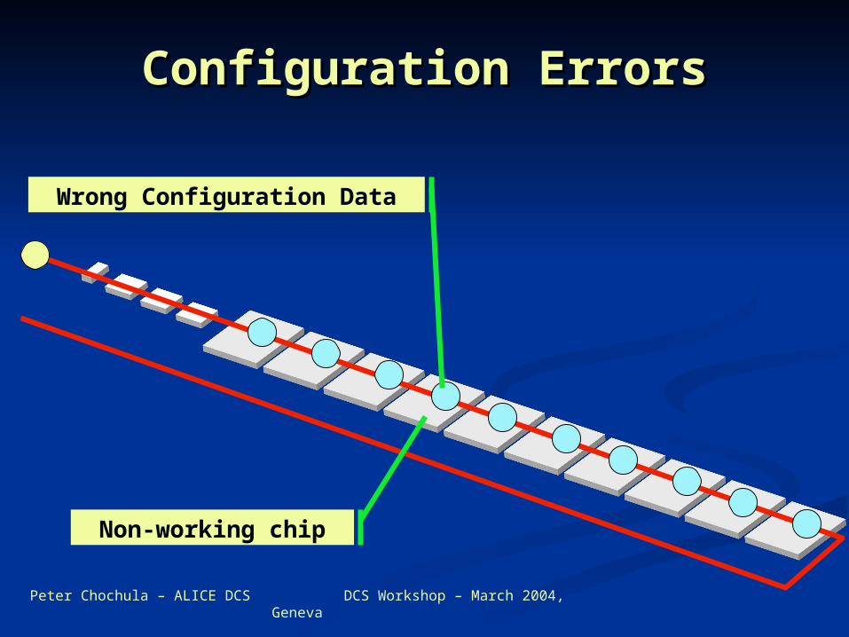
Configuration ErrorsConfiguration Errors
Wrong Configuration Data
Non-working chip
Peter Chochula – ALICE DCS DCS Workshop – March 2004, Geneva
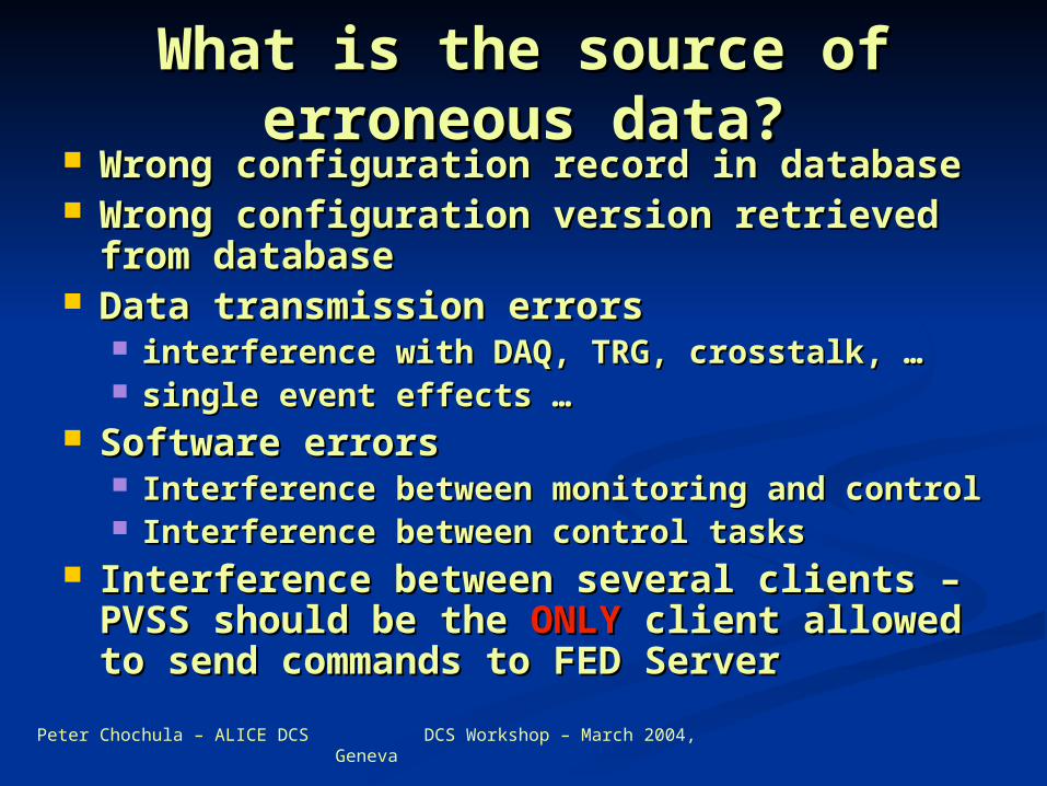
What is the source of What is the source of erroneous data?erroneous data?
Wrong configuration record in databaseWrong configuration record in database Wrong configuration version retrieved Wrong configuration version retrieved
from databasefrom database Data transmission errorsData transmission errors
interference with DAQ, TRG, crosstalk, …interference with DAQ, TRG, crosstalk, … single event effects …single event effects …
Software errorsSoftware errors Interference between monitoring and controlInterference between monitoring and control Interference between control tasksInterference between control tasks
Interference between several clients – Interference between several clients – PVSS should be the PVSS should be the ONLYONLY client allowed client allowed to send commands to FED Serverto send commands to FED Server
Peter Chochula – ALICE DCS DCS Workshop – March 2004, Geneva
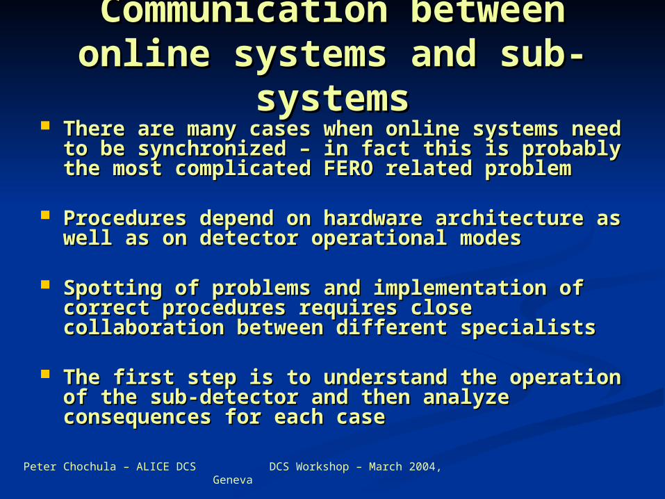
Communication between Communication between online systems and sub-online systems and sub-
systemssystems There are many cases when online systems There are many cases when online systems
need to be synchronized – in fact this is need to be synchronized – in fact this is probably the most complicated FERO related probably the most complicated FERO related problemproblem
Procedures depend on hardware architecture Procedures depend on hardware architecture as well as on detector operational modesas well as on detector operational modes
Spotting of problems and implementation of Spotting of problems and implementation of correct procedures requires close collaboration correct procedures requires close collaboration between different specialistsbetween different specialists
The first step is to understand the operation of The first step is to understand the operation of the sub-detector and then analyze the sub-detector and then analyze consequences for each caseconsequences for each case
Peter Chochula – ALICE DCS DCS Workshop – March 2004, Geneva
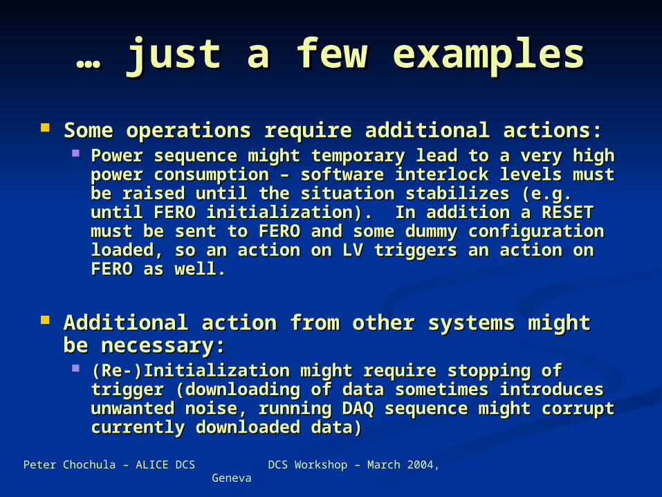
… … just a few examplesjust a few examples
Some operations require additional actions:Some operations require additional actions: Power sequence might temporary lead to a very high Power sequence might temporary lead to a very high
power consumption – software interlock levels must power consumption – software interlock levels must be raised until the situation stabilizes (e.g. until be raised until the situation stabilizes (e.g. until FERO initialization). In addition a RESET must be FERO initialization). In addition a RESET must be sent to FERO and some dummy configuration loaded, sent to FERO and some dummy configuration loaded, so an action on LV triggers an action on FERO as so an action on LV triggers an action on FERO as well.well.
Additional action from other systems might be Additional action from other systems might be necessary:necessary: (Re-)Initialization might require stopping of trigger (Re-)Initialization might require stopping of trigger
(downloading of data sometimes introduces (downloading of data sometimes introduces unwanted noise, running DAQ sequence might unwanted noise, running DAQ sequence might corrupt currently downloaded data)corrupt currently downloaded data)
Peter Chochula – ALICE DCS DCS Workshop – March 2004, Geneva
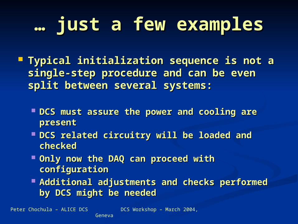
… … just a few examplesjust a few examples
Typical initialization sequence is not a Typical initialization sequence is not a single-step procedure and can be even single-step procedure and can be even split between several systems:split between several systems:
DCS must assure the power and cooling are DCS must assure the power and cooling are presentpresent
DCS related circuitry will be loaded and DCS related circuitry will be loaded and checkedchecked
Only now the DAQ can proceed with Only now the DAQ can proceed with configurationconfiguration
Additional adjustments and checks performed Additional adjustments and checks performed by DCS might be neededby DCS might be needed
Peter Chochula – ALICE DCS DCS Workshop – March 2004, Geneva
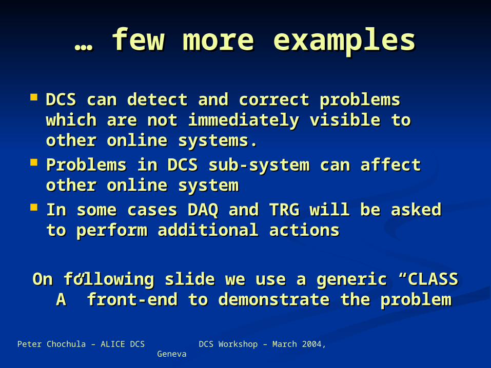
… … few more examplesfew more examples
DCS can detect and correct problems DCS can detect and correct problems which are not immediately visible to other which are not immediately visible to other online systems. online systems.
Problems in DCS sub-system can affect Problems in DCS sub-system can affect other online systemother online system
In some cases DAQ and TRG will be asked In some cases DAQ and TRG will be asked to perform additional actionsto perform additional actions
On following slide we use a generic “CLASS On following slide we use a generic “CLASS A” front-end to demonstrate the problemA” front-end to demonstrate the problem
Peter Chochula – ALICE DCS DCS Workshop – March 2004, Geneva
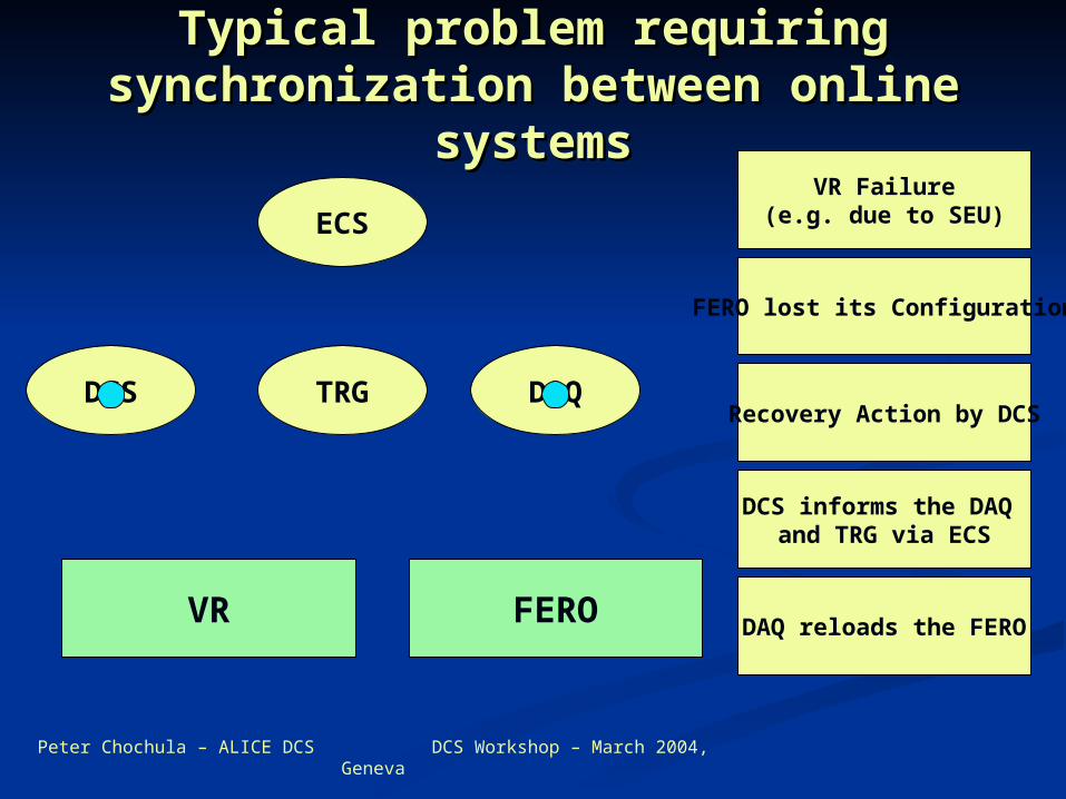
Typical problem requiring Typical problem requiring synchronization between online synchronization between online
systemssystems
DCS DAQTRG
FEROVR
ECSVR Failure
(e.g. due to SEU)
Recovery Action by DCS
FERO lost its Configuration
DCS informs the DAQ and TRG via ECS
DAQ reloads the FERO
Peter Chochula – ALICE DCS DCS Workshop – March 2004, Geneva
Propagation of hardware Propagation of hardware related problemsrelated problems
Problems can propagate between sub-Problems can propagate between sub-systems and affect different parts of the systems and affect different parts of the detector:detector: E.g. recovery of a VR failure could lead to E.g. recovery of a VR failure could lead to
corruption of configuration in neighboring sector corruption of configuration in neighboring sector (spikes, etc.).(spikes, etc.).
Such problems can remain hidden (e.g. Such problems can remain hidden (e.g. change in threshold settings) and will be change in threshold settings) and will be discovered only by offlinediscovered only by offline
If we are aware of potential problems we If we are aware of potential problems we could maybe use a simple procedure to could maybe use a simple procedure to correct them before they badly affect the correct them before they badly affect the data data
Peter Chochula – ALICE DCS DCS Workshop – March 2004, Geneva
Things to be understoodThings to be understood
In principle every single chip can be acessed In principle every single chip can be acessed individually. Allowing for such access would individually. Allowing for such access would lead to complications for some architectureslead to complications for some architectures Example: rather than creating a service for each Example: rather than creating a service for each
individual temperature sensor we could create individual temperature sensor we could create groups for sub-detector modules and publish all groups for sub-detector modules and publish all data togetherdata together
This requires balancing between number of This requires balancing between number of services and update rates (we should not update services and update rates (we should not update a service with 1000 values if only one value a service with 1000 values if only one value changes, but we also do not want to have 1000 changes, but we also do not want to have 1000 individual services instead) individual services instead)
Partitioning of sub-detectors should be done Partitioning of sub-detectors should be done very carefully (taking into account both very carefully (taking into account both control and monitoring aspects)control and monitoring aspects)
Peter Chochula – ALICE DCS DCS Workshop – March 2004, Geneva
A few more things to be A few more things to be understoodunderstood
What should be the structure of DIM What should be the structure of DIM commands?commands? Command structure should include the target and Command structure should include the target and
data to be transferred. data to be transferred. Should we define standards for payload or set Should we define standards for payload or set
weak rules? The segmentation and naming differs weak rules? The segmentation and naming differs between sub-detectors, definition of common between sub-detectors, definition of common standard would not be intuitive and therefore will standard would not be intuitive and therefore will lead to errors.lead to errors.
It is essential to create a naming convention It is essential to create a naming convention for each detector and understand its for each detector and understand its segmentation in terms of control, DAQ segmentation in terms of control, DAQ readout and monitoring.readout and monitoring.
Peter Chochula – ALICE DCS DCS Workshop – March 2004, Geneva
Still some question Still some question marksmarks
What is the amount of data to be What is the amount of data to be exchanged between DCS and FERO exchanged between DCS and FERO and at what frequencies?and at what frequencies?
What is the structure of this dataWhat is the structure of this data Example: temperatures for given sector Example: temperatures for given sector
can be sent as an array containing can be sent as an array containing values for each probe. Another approach values for each probe. Another approach would be to send data structure would be to send data structure containing only values which have containing only values which have changed and decode this information in changed and decode this information in PVSSIIPVSSII
Peter Chochula – ALICE DCS DCS Workshop – March 2004, Geneva
……yet another oneyet another one
What should be the granularity of agents?What should be the granularity of agents? Should we set common deadbands for all values Should we set common deadbands for all values
acquired by the individual agent? (e.g. update acquired by the individual agent? (e.g. update temperature readings if any of them changes by temperature readings if any of them changes by more that 0.5C) – PVSSII will of course provide more that 0.5C) – PVSSII will of course provide another level of filtering of these values another level of filtering of these values
Should be the deadbands set more precise? Should be the deadbands set more precise? (e.g. allowing for masking of faulty sensor at (e.g. allowing for masking of faulty sensor at the level of FED server)the level of FED server)
All answers depend on individual All answers depend on individual architectures.architectures.
Peter Chochula – ALICE DCS DCS Workshop – March 2004, Geneva
How to proceed?How to proceed? Working and stable FED server is the Working and stable FED server is the
starting point. It can be developed in starting point. It can be developed in advance – using emulators in the advance – using emulators in the hardware access layerhardware access layer
Once the hardware arrives, one could Once the hardware arrives, one could fully concentrate on operational fully concentrate on operational aspects. New procedures will be aspects. New procedures will be discoverred with time and can be discoverred with time and can be implemented in softwareimplemented in software
Communication with other sub-Communication with other sub-detectors is essential. DCS team is detectors is essential. DCS team is happy to assist you in this point.happy to assist you in this point.