Embed Size (px)
Citation preview
Control Algorithm Modeling GuidelinesUsing MATLAB®, Simulink®, and Stateflow®
Version 5.0
MathWorks Advisory Board (MAB)
1
History Date RevisionFebruary 2001 Initial document Release, Version 1.00April 2007 Version 2.00, Update releaseJuly 2011 Version 2.20, Update releaseAugust 2012 Version 3.0, Update releaseMarch 2020 Version 5.0, MAAB guidelines revised and reintroduced as
the MathWorks Advisory Board (MAB) Modeling Guidelines
Trademarks MATLAB, Simulink, and Stateflow are registered trademarks of The MathWorks, Inc. See www.mathworks.com/trademarks for a list of additional trademarks. Other product or brand names may be trademarks or registered trademarks of their respective holders.
2
Table of Contents
1. Introduction............................................................................................................8
1.1. Purpose of the guidelines.............................................................................................................8
1.2. Guideline template........................................................................................................................8Rule ID 9Sub ID Recommendations 9MATLAB® Versions 9Sub ID 9Title 9Description 9Custom Parameters 10Rational 10See Also 10
2. Naming Conventions...........................................................................................11
2.1. General Conventions.................................................................................................................. 11ar_0001: Usable characters for file names 11ar_0002: Usable characters for folder names 12jc_0241: Length restriction for model file names 13jc_0242: Length restriction for folder names 13
2.2. Content Conventions.................................................................................................................. 14jc_0201: Usable characters for subsystem names 14jc_0231: Usable characters for block names 15jc_0211: Usable characters for Inport block and Outport block 17jc_0243: Length restriction for subsystem names 19jc_0247: Length restriction for block names 19jc_0244: Length restriction for Inport and Outport names 19jc_0222: Usable characters for signal/bus names 20jc_0232: Usable characters for parameter names 20jc_0245: Length restriction for signal and bus names 21jc_0246: Length restriction for parameter names 22jc_0795: Usable characters for Stateflow data names 22jc_0796: Length restriction for Stateflow data names 23jc_0791: Duplicate data name definitions 23jc_0792: Unused data 24jc_0700: Unused data in Stateflow block 24na_0019: Restricted Variable Names 25
3. Simulink................................................................................................................26
3.1. Configuration Parameters...........................................................................................................26jc_0011: Optimization parameters for Boolean data types 26jc_0642: Integer rounding mode setting 26jc_0806: Detecting incorrect calculation results 27jc_0021: Model diagnostic settings 28
3.2. Diagram appearance................................................................................................................... 28na_0004: Simulink model appearance settings 28db_0043: Model font and font size 30jm_0002: Block resizing 30db_0142: Position of block names 31
3
jc_0061: Display of block names 32db_0140: Display of block parameters 33jc_0603: Model description 34jc_0604: Using Block Shadow 35db_0081: Unconnected signals / blocks 36db_0032: Signal line connections 37db_0141: Signal flow in Simulink models 38jc_0110: Direction of block 41jc_0171: Clarification of connections between structural subsystems 42jc_0602: Consistency in model element names 44jc_0281: Trigger signal names 46db_0143: Usable block types in model hierarchy 49db_0144: Use of subsystems 50jc_0653: Delay block layout in feedback loops 52hd_0001: Prohibited Simulink sinks 53
3.3. Signal............................................................................................................................................ 54na_0010: Usage of vector and bus signals 54jc_0008: Definition of signal names 54jc_0009: Signal name propagation 55db_0097: Position of labels for signals and busses 61na_0008: Display of labels on signals 62na_0009: Entry versus propagation of signal labels 63db_0110: Block parameters 64db_0112: Usage of index 64jc_0645: Parameter definition for calibration 68jc_0641: Sample time setting 69jc_0643: Fixed-point setting 69jc_0644: Type setting 70
3.4. Conditional subsystem relations...............................................................................................71db_0146: Block layout in conditional subsystems 71jc_0640: Initial value settings for Outport blocks in conditional subsystems 72jc_0659: Usage restrictions of signal lines input to Merge blocks 74na_0003: Usage of If blocks 75jc_0656: Usage of Conditional Control blocks 76jc_0657: Retention of output value based on conditional control flow blocks and Merge blocks 77
3.5. Operation blocks......................................................................................................................... 81na_0002: Appropriate usage of basic logical and numerical operations 81jc_0121: Usage of add and subtraction blocks 84jc_0610: Operator order for multiplication and division blocks 86jc_0611: Input sign for multiplication and division blocks 88jc_0794: Division in Simulink 88jc_0805: Numerical operation block inputs 89jc_0622: Usage of Fcn blocks 96jc_0621: Usage of Logical Operator blocks 96jc_0131: Usage of Relational Operator blocks 97jc_0800: Comparing floating-point types in Simulink 98jc_0626: Usage of Lookup Table blocks 98jc_0623: Usage of continuous-time Delay blocks and discrete-time Delay blocks 99jc_0624: Usage of Tapped Delay blocks/Delay blocks 100jc_0627: Usage of Discrete-Time Integrator blocks 101jc_0628: Usage of Saturation blocks 104jc_0651: Implementing a type conversion 104
3.6. Other blocks............................................................................................................................... 105db_0042: Usage of Inport and Outport blocks 105jc_0081: Inport/Outport block icon display 108na_0011: Scope of Goto/From blocks 109
4
jc_0161: Definition of Data Store Memory blocks 109jc_0141: Usage of Switch blocks 109jc_0650: Block input/output data type with switching function 110jc_0630: Usage of Multiport Switch blocks 111na_0020: Number of inputs to variant subsystems 113na_0036: Default variant 114na_0037: Use of single variable for variant condition 115
4. Stateflow.............................................................................................................116
4.1. Stateflow blocks/data/events....................................................................................................116db_0122: Stateflow and Simulink interface signals and parameters 116db_0123: Stateflow port names 117db_0125: Stateflow local data 118db_0126: Defining Stateflow events 122jc_0701: Usable number for first index 124jc_0712: Execution timing for default transition path 126jc_0722: Local data definition in parallel states 127
4.2. Stateflow diagram...................................................................................................................... 128jc_0797: Unconnected transitions / states / connective junctions 128db_0137: States in state machines 130jc_0721: Usage of parallel states 131db_0129: Stateflow transition appearance 132jc_0531: Default transition 135jc_0723: Prohibited direct transition from external state to child state 142jc_0751: Backtracking prevention in state transition 144jc_0760: Starting point of internal transition 145jc_0763: Usage of multiple internal transitions 147jc_0762: Prohibition of state action and flow chart combination 150db_0132: Transitions in flow charts 152jc_0773: Unconditional transition of a flow chart 154jc_0775: Terminating junctions in flow charts 157jc_0738: Usage of Stateflow comments 158
4.3. Conditional transition / Action.................................................................................................160jc_0790: Action language of Chart block 160jc_0702: Use of named Stateflow parameters/constants 161jm_0011: Pointers in Stateflow 162jc_0491: Reuse of Stateflow data 163jm_0012: Usage restrictions of events and broadcasting events 165jc_0733: Order of state action types 169jc_0734: Number of state action types 170jc_0740: Limitation on use of exit state action 171jc_0741: Timing to update data used in state chart transition conditions 172jc_0772: Execution order and transition conditions of transition lines 173jc_0753: Condition actions and transition actions in Stateflow 175jc_0711: Division in Stateflow 177db_0127: Limitation on MATLAB commands in Stateflow blocks 180jc_0481: Use of hard equality comparisons for floating point numbers in Stateflow 182na_0001: Standard usage of Stateflow operators 183jc_0655: Prohibition of logical value comparison in Stateflow 186jc_0451: Use of unary minus on unsigned integers 187jc_0802: Prohibited use of implicit type casting in Stateflow 188jc_0803: Passing values to library functions 190
4.4. Label description....................................................................................................................... 192jc_0732: Distinction between state names, data names, and event names 192jc_0730: Unique state name in Stateflow blocks 193
5
jc_0731: State name format 194jc_0501: Line breaks in state labels 194jc_0736: Uniform indentations in Stateflow blocks 195jc_0739: Describing text inside states 197jc_0770: Position of transition label 199jc_0771: Comment position in transition labels 201jc_0752: Condition action in transition label 204jc_0774: Comments for through transition 204
4.5. Miscellaneous............................................................................................................................ 205jc_0511: Return values from a graphical function 205jc_0804: Prohibited use of recursive calls with graphical functions 206na_0042: Usage of Simulink functions 208na_0039: Limitation on Simulink functions in Chart blocks 209
5. MATLAB..............................................................................................................210
5.1. MATLAB Appearance................................................................................................................210na_0018: Number of nested if/else and case statements 210na_0025: MATLAB Function headers 210
5.2. MATLAB Data and Operations.................................................................................................211na_0024: Shared data in MATLAB functions 211na_0031: Definition of default enumerated value 213na_0034: MATLAB Function block input/output settings 214
5.3. MATLAB Usage.......................................................................................................................... 214na_0016: Source lines of MATALAB Functions 214na_0017: Number of called function levels 214na_0021: Strings in MATLAB functions 215na_0022: Recommended patters for Switch/Case statements 216jc_0801: Prohibited use of the /* and */ comment symbols 217
6. Glossary.............................................................................................................219
7. Determining Guideline Operation Rules..........................................................221
7.1. Process Definition and Development Environment...............................................................221
7.2. MATLAB/Simulink Version.......................................................................................................221
7.3. MATLAB/Simulink Settings......................................................................................................221
7.4. Usable Blocks............................................................................................................................ 221
7.5. Using Optimization and Configuration Parameters................................................................222Optimization parameters 222Configuration Parameters 222
7.6. Applying Guidelines for a Project............................................................................................222Using the model analysis process when applying guidelines 222Adoption of the guideline rule and process settings 223Setting the guideline rule application field and the clarifying the exclusion condition 223Parameter recommendations in the guidelines 223Verifying adherence to the guidelines 223Modifying adherence to a guideline 223
6
8. Model Architecture Explanation.......................................................................225
8.1. Roles of Simulink and Stateflow..............................................................................................225
8.2. Hierarchical Structure of a Controller Model..........................................................................226Types of Hierarchies 226Top Layer 226Function Layers and Sub-Function Layers 227Schedule Layers 228Control Flow Layers 229Selection Layers 230Data Flow Layers 231
8.3. Relationship between Simulink Models and Embedded Implementation.............................231
9. Appendices........................................................................................................236
9.1. Simulink Functions................................................................................................................... 236
9.2. Stateflow Functions.................................................................................................................. 239
9.3. Initialization................................................................................................................................ 245
9.4. Miscellaneous............................................................................................................................ 249
9.5. Modeling Knowledge / Usage Patterns....................................................................................251Appendix 1: Simulink Patterns for If, elseif, else Constructs 251Appendix 2: Simulink Patterns for Case Constructs 251Appendix 3: Simulink Patterns for Logical Constructs 252Appendix 4: Simulink Patterns for Vector Signals 253Appendix 5: Using Switch and if-then-else Action Subsystems 255Appendix 6: Use of if, elseif, else Action Subsystem to Replace Multiple Switches 256Appendix 7: Usage Rules for Action Subsystems Using Conditional Control Flow 260Appendix 8: Tests for Information From Errors 263Appendix 9: Flow Chart Patterns for Conditions 264Appendix 10: Flow Chart Patterns for Condition Actions 265Appendix 11: Flow Chart Patterns for if Constructs 266Appendix 12: Flow Chart Patterns for Case Constructs 268Appendix 13: Flow Chart Patterns for Loop Constructs 268Appendix 14: State Machine Patterns for Conditions 270Appendix 15: State Machine Patterns for Transition Actions 270Appendix 16: Limiting State Layering 271Appendix 17: Number of States per Stateflow Container 271Appendix 18: Function Call from Stateflow 272Appendix 19: Function Types Available in Stateflow 272
7
1. Introduction
1.1. Purpose of the guidelinesMathWorks Advisory Board (MAB) guidelines stipulate important basic rules for modeling in Simulink
and Stateflow. The overall purpose of these modeling guidelines is to allow for a simple, common understanding by modelers and consumers of control system models.
The main objectives of these guidelines are: Readability
Improve graphical understandability Improve readability of functional analysis Prevent connection mistakes Comments, etc.
Simulation and verification Mechanism to enable simulation Testability
Code Generation Improve the efficiency of code generation (ROM, RAM efficiency) Ensure the robustness of generated code
Model runtime errors and recommendations that cannot be implemented are outside of the scope of these rules.
The chapters of this document provide the following information: Chapter 1 ― Intent of these guidelines and an overview of the guideline template.Chapters 2 through 5 ― Guideline rulesChapter 6 ― Glossary Chapter 7 ― Process for evaluating and implementing guidelines for your projectChapters 8 ― Model architecture and operations that are required for advanced users.Chapter 9 ― Additional explanation and modelling information for Simulink/Stateflow functions, including
modeling patterns.
1.2. Guideline templateGuidelines are documented by using a standard template. Use of this template is recommended when
creating original guidelines.
Note: This template specifies the minimum requirements that are needed to understand a guideline. New items can be added to the template as long as they do not duplicate existing information.
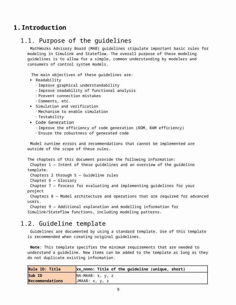
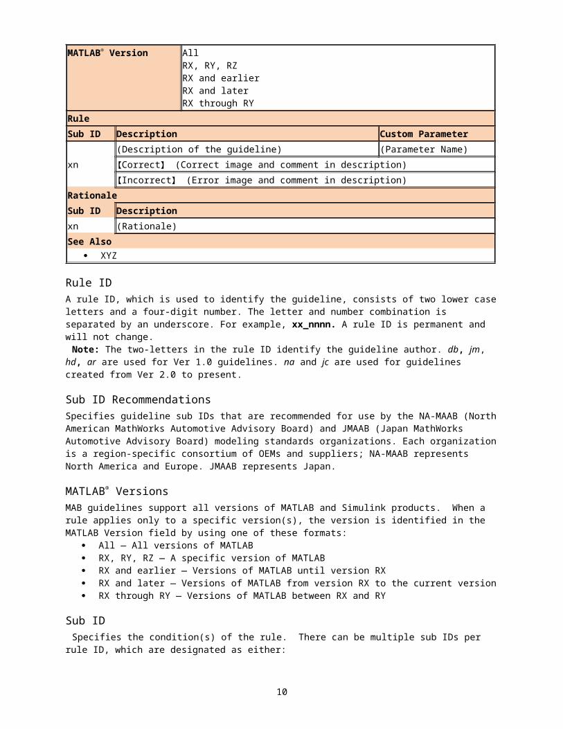
Rule ID: Title xx_nnnn: Title of the guideline (unique, short)Sub ID Recommendations
NA-MAAB: x, y, zJMAAB: x, y, z
MATLAB® Version AllRX, RY, RZRX and earlierRX and laterRX through RY
RuleSub ID Description Custom Parameter
xn
(Description of the guideline) (Parameter Name)【Correct】 (Correct image and comment in description)
【Incorrect】 (Error image and comment in description)Rationale
8
Sub ID Descriptionxn (Rationale)See Also
XYZ
Rule IDA rule ID, which is used to identify the guideline, consists of two lower case letters and a four-digit number. The letter and number combination is separated by an underscore. For example, xx_nnnn. A rule ID is permanent and will not change.
Note: The two-letters in the rule ID identify the guideline author. db, jm, hd, ar are used for Ver 1.0 guidelines. na and jc are used for guidelines created from Ver 2.0 to present.
Sub ID RecommendationsSpecifies guideline sub IDs that are recommended for use by the NA-MAAB (North American MathWorks Automotive Advisory Board) and JMAAB (Japan MathWorks Automotive Advisory Board) modeling standards organizations. Each organization is a region-specific consortium of OEMs and suppliers; NA-MAAB represents North America and Europe. JMAAB represents Japan.
MATLAB® VersionsMAB guidelines support all versions of MATLAB and Simulink products. When a rule applies only to a specific version(s), the version is identified in the MATLAB Version field by using one of these formats:
All — All versions of MATLAB RX, RY, RZ — A specific version of MATLAB RX and earlier — Versions of MATLAB until version RX RX and later — Versions of MATLAB from version RX to the current version RX through RY — Versions of MATLAB between RX and RY
Sub IDSpecifies the condition(s) of the rule. There can be multiple sub IDs per rule ID, which are designated as
either: Selectable ― Consist of one lower-case letter (alphabetical order). The choice of whether to
adopt a selectable sub ID is left to the user. Mutually Exclusive ― Consist of one lower case letter (alphabetical order) and a single-digit
number. When choosing to accept or reject a mutually exclusive sub ID, only one option can be selected.
Example xy_0000 → xy_0000a Selectable (user’s choice) → xy_0000b1 Mutually Exclusive (if using, choose from xy_0000b1 or xy_0000b2) → xy_0000b2 Mutually Exclusive (if using, choose from xy_0000b1 or xy_0000b2)
TitleThe title is unique and provides a brief description of the guidelines.
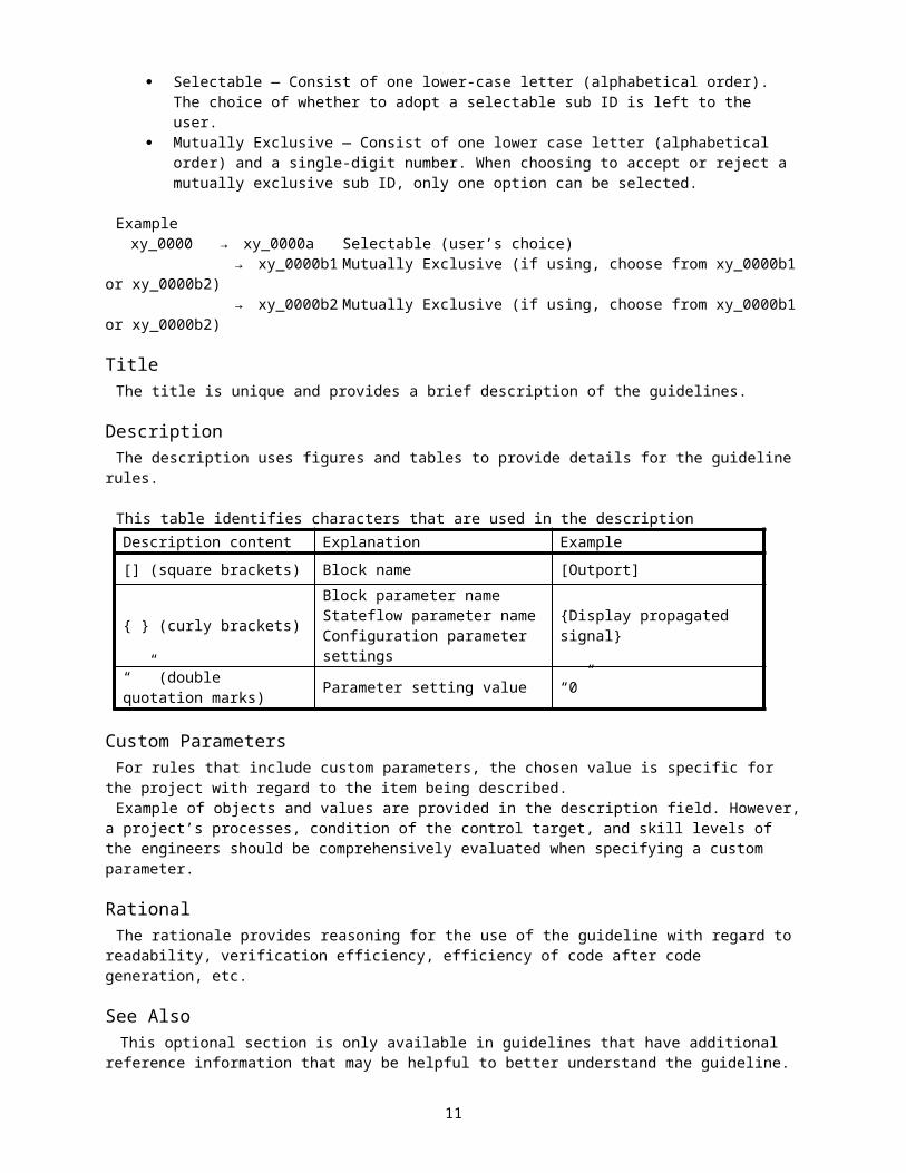
DescriptionThe description uses figures and tables to provide details for the guideline rules.
This table identifies characters that are used in the descriptionDescription content Explanation Example
[] (square brackets) Block name [Outport]
{ } (curly brackets)Block parameter nameStateflow parameter nameConfiguration parameter settings
{Display propagated signal}
“ ” (double quotation marks) Parameter setting value “0”
9
Custom ParametersFor rules that include custom parameters, the chosen value is specific for the project with regard to the
item being described.Example of objects and values are provided in the description field. However, a project’s processes,
condition of the control target, and skill levels of the engineers should be comprehensively evaluated when specifying a custom parameter.
RationalThe rationale provides reasoning for the use of the guideline with regard to readability, verification
efficiency, efficiency of code after code generation, etc.
See AlsoThis optional section is only available in guidelines that have additional reference information that may
be helpful to better understand the guideline.
10
2. Naming Conventions
2.1. General Conventions
ar_0001: Usable characters for file namesRule ID: Title ar_0001: Usable characters for file namesSub ID Recommendations
NA-MAAB: a, b, c, d, e, f, gJMAAB: a, b, c, d, e, f, g
MATLAB® Version AllRuleSub ID Description Custom Parameter
a Only these character types shall be used in file names: single-byte alphanumeric characters (a-z, A-Z, 0-9) single-byte underscore (_)
Line breaks, single-byte spaces, double-byte characters, and control characters shall not be used.
File types that are checked for model and MATLAB files shall be set in the project settings.
File (extension)
【Incorrect】MAB Model.slx Single-byte spaces are used.JMAAB設定.m Double-byte characters are used.NA-MAABModel.pJMAAB(Model).mdl Symbol characters are used.
b The file name shall not use numbers at the beginning. File (extension)【Incorrect】
001_JMAABModel.slxc The file name shall not use underscores at the
beginning.File (extension)
【Incorrect】_JMAABModel.slx
d The file name shall not use an underscore at the end. File (extension)【Incorrect】
MABModel_.slxe The file name shall not use consecutive underscores. File (extension)
【Incorrect】JMAAB__Model.slx
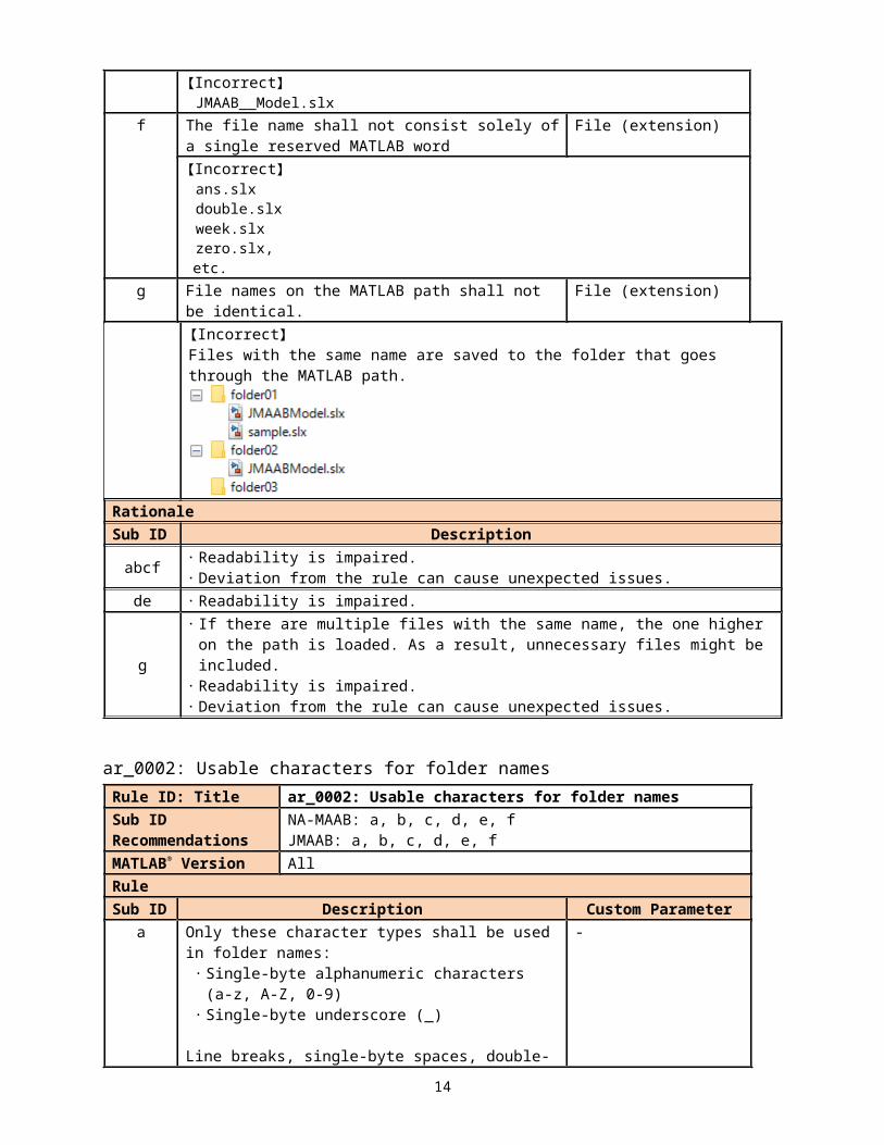
f The file name shall not consist solely of a single reserved MATLAB word
File (extension)
【Incorrect】ans.slxdouble.slxweek.slxzero.slx, etc.
g File names on the MATLAB path shall not be identical. File (extension)【Incorrect】Files with the same name are saved to the folder that goes through the MATLAB path.
11

RationaleSub ID Description
abcf Readability is impaired. Deviation from the rule can cause unexpected issues.
de Readability is impaired.
g
If there are multiple files with the same name, the one higher on the path is loaded. As a result, unnecessary files might be included.
Readability is impaired. Deviation from the rule can cause unexpected issues.
ar_0002: Usable characters for folder namesRule ID: Title ar_0002: Usable characters for folder namesSub ID Recommendations
NA-MAAB: a, b, c, d, e, fJMAAB: a, b, c, d, e, f
MATLAB® Version AllRuleSub ID Description Custom Parameter
a Only these character types shall be used in folder names: Single-byte alphanumeric characters (a-z, A-Z, 0-9) Single-byte underscore (_)
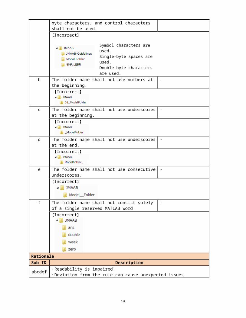
Line breaks, single-byte spaces, double-byte characters, and control characters shall not be used.
-
【Incorrect】
Symbol characters are used.Single-byte spaces are used.Double-byte characters are used.
b The folder name shall not use numbers at the beginning.
-
【Incorrect】
c The folder name shall not use underscores at the beginning.
-
【Incorrect】
d The folder name shall not use underscores at the end. - 【Incorrect】
e The folder name shall not use consecutive -
12

underscores.【Incorrect】
f The folder name shall not consist solely of a single reserved MATLAB word.
-
【Incorrect】
RationaleSub ID Description
abcdef Readability is impaired. Deviation from the rule can cause unexpected issues.
jc_0241: Length restriction for model file namesRule ID: Title jc_0241: Length restriction for model file namesSub ID Recommendations
NA-MAAB: aJMAAB: a
MATLAB® Version AllRuleSub ID Description Custom Parameter
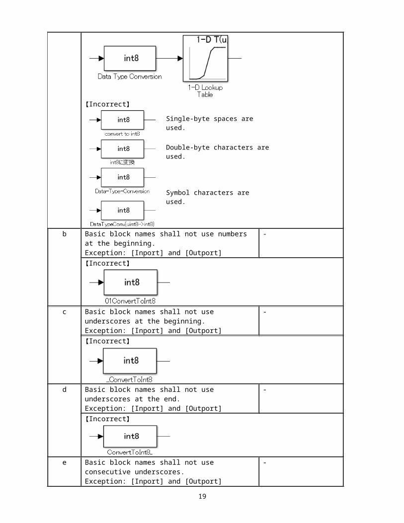
a Model file name length shall be a maximum of 63 characters (not including dots and extension).
Maximum model file name length
RationaleSub ID Description
a Possible that a long file name cannot be referred to in the model reference.
jc_0242: Length restriction for folder namesRule ID: Title jc_0242: Length restriction for folder namesSub ID Recommendations
NA-MAAB: aJMAAB: a
MATLAB® Version AllRuleSub ID Description Custom Parameter
a Folder name length shall be a maximum of 63 characters.
Maximum folder name length
RationaleSub ID Description
a Possible that the full path name cannot be display in the user interface.
13
2.2. Content Conventions
jc_0201: Usable characters for subsystem namesRule ID: Title jc_0201: Usable characters for subsystem namesSub ID Recommendations NA-MAAB: a, b, c, d, e, f
JMAAB: a, b, c, d, e, fMATLAB® Version AllRuleSub ID Description Custom Parameter
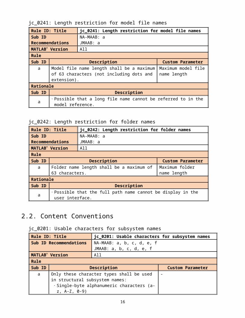
a Only these character types shall be used in structural subsystem names: Single-byte alphanumeric characters (a-z, A-Z, 0-9) Single-byte underscore (_)
Line breaks, single-byte spaces, double-byte characters, and control characters shall not be used.
-
【Incorrect】
Uses single-byte spaces.
Uses double-byte characters.
Uses symbol characters.
b A structural subsystem name shall not use numbers at the beginning.
-
【Incorrect 】
c A structural subsystem name shall not use an underscore at the beginning.
-
【Incorrect 】
d A structural subsystem name shall not use an underscore at the end.
-
【Incorrect】
14
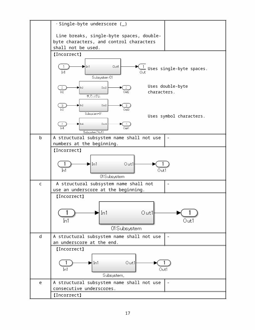
e A structural subsystem name shall not use consecutive underscores.
-
【Incorrect】
f A structural subsystem name shall not consist solely of a single reserved MATLAB word.
-
【Incorrect 】
RationaleSub ID Description
abf Cannot generate code using the configured structural subsystem name.cde May not be able to generate code using the configured structural subsystem name.
jc_0231: Usable characters for block namesRule ID: Title jc_0231: Usable characters for block namesSub ID Recommendations
NA-MAAB: a, b, c, d, e, fJMAAB: a, b, c, d, e, f
MATLAB® Version AllRuleSub ID Description Custom Parameter
a Only these character types shall be used for basic block names: Single-byte alphanumeric characters (a-z, A-Z, 0-9) Single-byte underscore (_)
Exception: [Inport] and [Outport]
Line breaks and single-byte spaces shall not be permitted when adding a new block name. However, they shall be permitted when used initially as a block name that is saved in the Simulink library.
Double-byte characters and control characters shall not be used.
-
15
【Correct】Block names registered in the Simulink library.
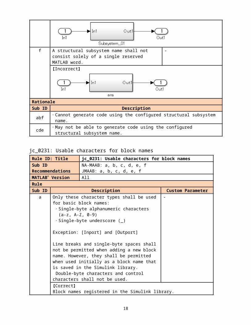
【Incorrect】
Single-byte spaces are used.
Double-byte characters are used.
Symbol characters are used.
b Basic block names shall not use numbers at the beginning.Exception: [Inport] and [Outport]
-
【Incorrect】
c Basic block names shall not use underscores at the beginning.Exception: [Inport] and [Outport]
-
【Incorrect】
d Basic block names shall not use underscores at the end.Exception: [Inport] and [Outport]
-
【Incorrect】
e Basic block names shall not use consecutive underscores.Exception: [Inport] and [Outport]
-
【Incorrect】
16
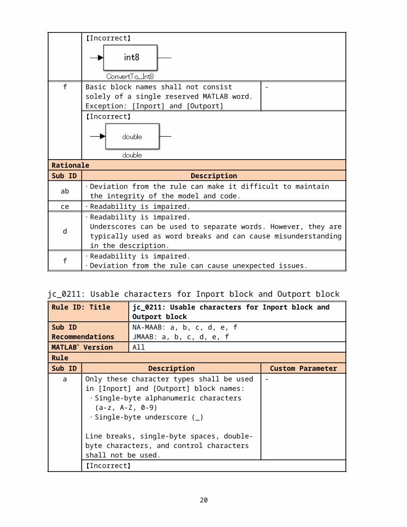
f Basic block names shall not consist solely of a single reserved MATLAB word.Exception: [Inport] and [Outport]
-
【Incorrect】
RationaleSub ID Description
ab Deviation from the rule can make it difficult to maintain the integrity of the model and code.
ce Readability is impaired.
d Readability is impaired.
Underscores can be used to separate words. However, they are typically used as word breaks and can cause misunderstanding in the description.
f Readability is impaired. Deviation from the rule can cause unexpected issues.
jc_0211: Usable characters for Inport block and Outport blockRule ID: Title jc_0211: Usable characters for Inport block and Outport blockSub ID Recommendations
NA-MAAB: a, b, c, d, e, fJMAAB: a, b, c, d, e, f
MATLAB® Version AllRuleSub ID Description Custom Parameter
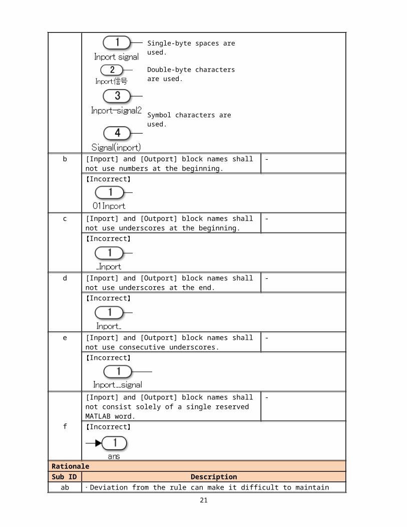
a Only these character types shall be used in [Inport] and [Outport] block names: Single-byte alphanumeric characters (a-z, A-Z, 0-9) Single-byte underscore (_)
Line breaks, single-byte spaces, double-byte characters, and control characters shall not be used.
-
【Incorrect】
Single-byte spaces are used.
Double-byte characters are used.
17
Symbol characters are used.
b [Inport] and [Outport] block names shall not use numbers at the beginning.
-
【Incorrect】
c [Inport] and [Outport] block names shall not use underscores at the beginning.
-
【Incorrect 】
d [Inport] and [Outport] block names shall not use underscores at the end.
-
【Incorrect】
e [Inport] and [Outport] block names shall not use consecutive underscores.
-
【Incorrect】
f
[Inport] and [Outport] block names shall not consist solely of a single reserved MATLAB word.
-
【Incorrect】
RationaleSub ID Description
ab Deviation from the rule can make it difficult to maintain the integrity of the model and code.
ce Readability is impaired.
d Readability is impaired. Underscores can be used to separate words. However, they are typically used as
word breaks and can cause misunderstanding in the description.
f Readability is impaired. Deviation from the rule can cause unexpected issues.
18
jc_0243: Length restriction for subsystem namesRule ID: Title jc_0243: Length restriction for subsystem namesSub ID Recommendations
NA-MAAB: aJMAAB: a
MATLAB® Version AllRuleSub ID Description Custom Parameter
a Structural subsystem name length shall be a maximum of 63 characters.
Maximum subsystem name length
RationaleSub ID Description
a Code generation may not be possible.
jc_0247: Length restriction for block namesRule ID: Title jc_0247: Length restriction for block namesSub ID Recommendations
NA-MAAB: aJMAAB: a
MATLAB® Version AllRuleSub ID Description Custom Parameter
a Basic block name length shall be a maximum of 63 characters.Exception: [Inport] and [Outport]
Maximum block name length
RationaleSub ID Description
a Code generation may not be possible.
jc_0244: Length restriction for Inport and Outport namesRule ID: Title jc_0244: Length restriction for Inport and Outport namesSub ID Recommendations
NA-MAAB: aJMAAB: a
MATLAB® Version AllRuleSub ID Description Custom Parameter
a [Inport] and [Outport] name length shall be a maximum of 63 characters.
Maximum Inport block name lengthMaximum Outport block name length
RationaleSub ID Description
a Code generation may not be possible.
jc_0222: Usable characters for signal/bus namesRule ID: Title jc_0222: Usable characters for signal/bus namesSub ID Recommendations
NA-MAAB: a, b, c, d, e, fJMAAB: a, b, c, d, e, f
MATLAB® Version AllRule
19
Sub ID Description Custom Parametera Only these character types shall be used in signal and
bus names: Single-byte alphanumeric characters (a-z, A-Z, 0-9) Single-byte underscore (_)
Line breaks, single-byte spaces, double-byte characters, and control characters shall not be used.
-
b Signal and bus names shall not use numbers at the beginning.
-
c The signal or bus name shall not use underscores at the beginning.
-
d Signal and bus names shall not use underscores at the end.
-
e Signal and bus names shall not use consecutive underscores.
-
f Signal and bus names shall not consist solely of a single reserved MATLAB word.
-
RationaleSub ID Description
ab Deviation from the rule can make it difficult to maintain the integrity of the model and code.
ce Readability is impaired.
d Readability is impaired.
Underscores can be used to separate words. However, they are typically used as word breaks and can cause misunderstanding in the description..
f Readability is impaired. Deviation from the rule can cause unexpected issues.
jc_0232: Usable characters for parameter namesRule ID: Title jc_0232: Usable characters for parameter namesSub ID Recommendations
NA-MAAB: d, eJMAAB: a, b, c, d, e, f
MATLAB® Version AllRuleSub ID Description Custom Parameter
a Only these character types shall be used in parameter names: Single-byte alphanumeric characters (a-z, A-Z, 0-9) Single-byte underscore (_)
Line break, single-byte space, double-byte characters, and control characters shall not be used.
-
b The parameter name shall not use numbers at the beginning.
-
c The parameter name shall not use underscores at the beginning.
-
d The parameter name shall not use underscores at the end.
-
e The parameter name shall not use consecutive underscores.
-
f The parameter name shall not consist solely of a single -
20
reserved MATLAB word.RationaleSub ID Description
ab Deviation from the rule can make it difficult to maintain the integrity of the model and code.
ce Readability is impaired.
d Readability is impaired.
Underscores can be used to separate words. However, they are typically used as word breaks and can cause misunderstanding in the description.
f Readability is impaired. Deviation from the rule can cause unexpected issues.
jc_0245: Length restriction for signal and bus namesRule ID: Title jc_0245: Length restriction for signal and bus namesSub ID Recommendations
NA-MAAB: aJMAAB: a
MATLAB® Version AllRuleSub ID Description Custom Parameter
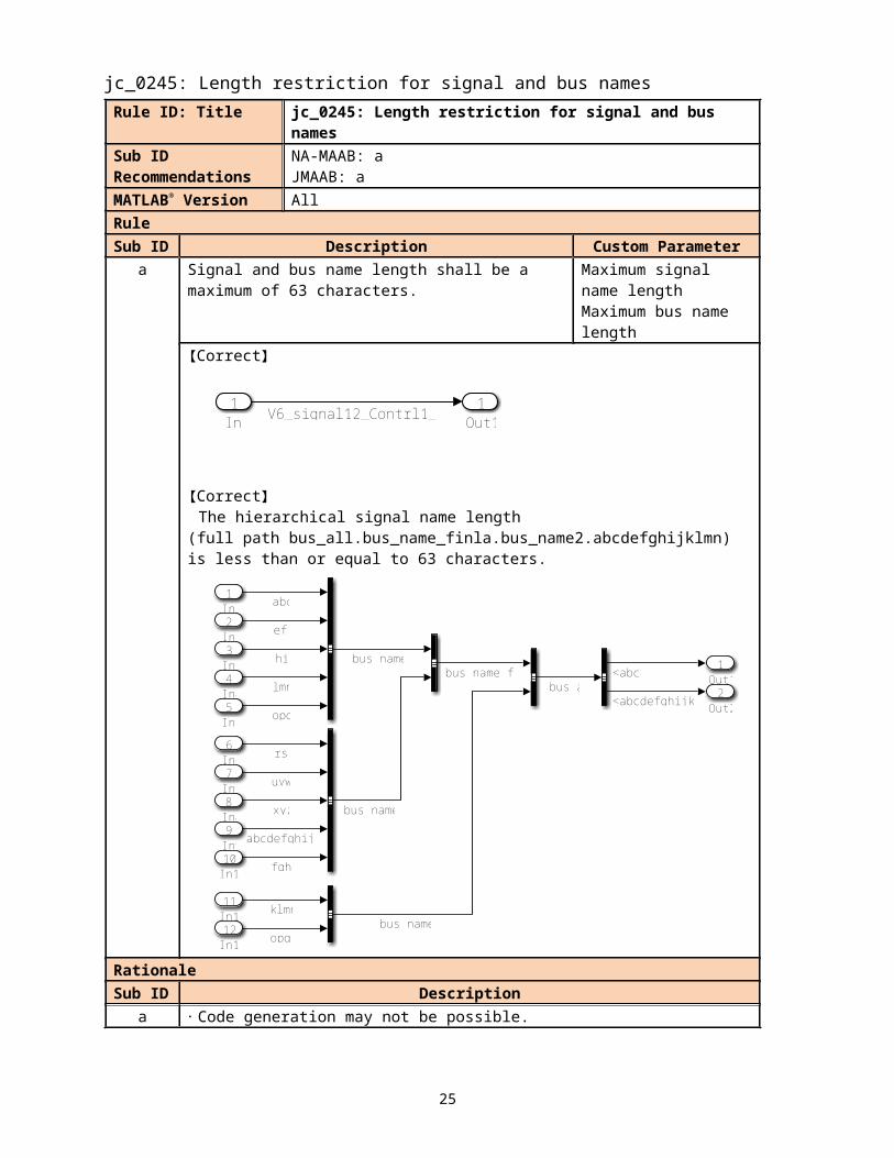
a Signal and bus name length shall be a maximum of 63 characters.
Maximum signal name lengthMaximum bus name length
【Correct】
1Out1
1In1 V6_signal12_Contrl1_EgRpm1
【Correct】The hierarchical signal name length
(full path bus_all.bus_name_finla.bus_name2.abcdefghijklmn) is less than or equal to 63 characters.
21
2Out2
1Out1
12In12
11In11
10In10
9In9
8In8
7In7
6In6
5In5
4In4
3In3
2In2
1In1 abc
efg
hij
lmn
opq
rst
uvw
xyz
abcdefghijklmn
fghij
klmn
opqr
bus_name1
bus_name2
bus_name_finla
bus_name3
bus_all<abc>
<abcdefghijklmn>
RationaleSub ID Description
a Code generation may not be possible.
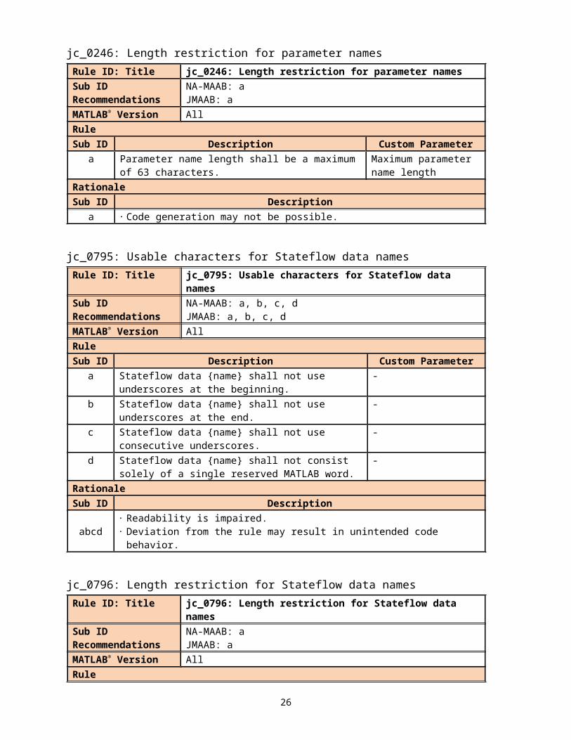
jc_0246: Length restriction for parameter namesRule ID: Title jc_0246: Length restriction for parameter namesSub ID Recommendations
NA-MAAB: aJMAAB: a
MATLAB® Version AllRuleSub ID Description Custom Parameter
a Parameter name length shall be a maximum of 63 characters.
Maximum parameter name length
RationaleSub ID Description
a Code generation may not be possible.
jc_0795: Usable characters for Stateflow data namesRule ID: Title jc_0795: Usable characters for Stateflow data namesSub ID Recommendations
NA-MAAB: a, b, c, dJMAAB: a, b, c, d
MATLAB® Version AllRuleSub ID Description Custom Parameter
a Stateflow data {name} shall not use underscores at the beginning.
-
b Stateflow data {name} shall not use underscores at the end.
-
c Stateflow data {name} shall not use consecutive -
22
underscores.d Stateflow data {name} shall not consist solely of a
single reserved MATLAB word.-
RationaleSub ID Description
abcd Readability is impaired. Deviation from the rule may result in unintended code behavior.
jc_0796: Length restriction for Stateflow data namesRule ID: Title jc_0796: Length restriction for Stateflow data namesSub ID Recommendations
NA-MAAB: aJMAAB: a
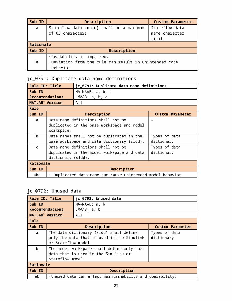
MATLAB® Version AllRuleSub ID Description Custom Parameter
a Stateflow data {name} shall be a maximum of 63 characters.
Stateflow data name character limit
RationaleSub ID Description
a Readability is impaired. Deviation from the rule can result in unintended code behavior
jc_0791: Duplicate data name definitionsRule ID: Title jc_0791: Duplicate data name definitionsSub ID Recommendations
NA-MAAB: a, b, cJMAAB: a, b, c
MATLAB® Version AllRuleSub ID Description Custom Parameter
a Data name definitions shall not be duplicated in the base workspace and model workspace.
-
b Data names shall not be duplicated in the base workspace and data dictionary (sldd).
Types of data dictionary
c Data name definitions shall not be duplicated in the model workspace and data dictionary (sldd).
Types of data dictionary
RationaleSub ID Description
abc Duplicated data name can cause unintended model behavior.
jc_0792: Unused dataRule ID: Title jc_0792: Unused dataSub ID Recommendations
NA-MAAB: a, bJMAAB: a, b
MATLAB® Version AllRuleSub ID Description Custom Parameter
a The data dictionary (sldd) shall define only the data that is used in the Simulink or Stateflow model.
Types of data dictionary
b The model workspace shall define only the data that is used in the Simulink or Stateflow model.
-
23
RationaleSub ID Description
ab Unused data can affect maintainability and operability.
jc_0700: Unused data in Stateflow blockRule ID: Title jc_0700: Unused data in Stateflow blockSub ID Recommendations
NA-MAAB: aJMAAB: a
MATLAB® Version AllRuleSub ID Description Custom Parameter
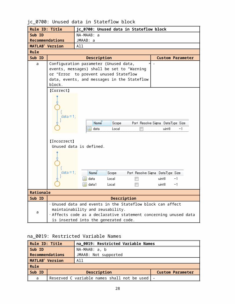
a Configuration parameter {Unused data, events, messages} shall be set to “Warning” or “Error” to prevent unused Stateflow data, events, and messages in the Stateflow block.
-
【Correct】
【Incorrect】
Unused data is defined.
RationaleSub ID Description
a
Unused data and events in the Stateflow block can affect maintainability and reusability.
Affects code as a declarative statement concerning unused data is inserted into the generated code.
na_0019: Restricted Variable NamesRule ID: Title na_0019: Restricted Variable NamesSub ID Recommendations
NA-MAAB: a, bJMAAB: Not supported
MATLAB® Version AllRuleSub ID Description Custom Parameter
a Reserved C variable names shall not be used as variable names in MATLAB code. For example, avoid using const, TRUE, FALSE, infinity, nil, double, single, or enum in MATLAB
-
24
code. b Variable names that conflict with MATLAB Functions,
such as conv, shall not be used.-
RationaleSub ID Description
ab Improves readability of the code. Code generation may not be possible.
25
3. Simulink
3.1. Configuration Parameters
jc_0011: Optimization parameters for Boolean data typesRule ID: Title jc_0011: Optimization parameters for Boolean data typesSub ID Recommendations
NA-MAAB: aJMAAB: a
MATLAB® Version AllRuleSub ID Description Custom Parameter
a Configuration parameter {Implement logic signals as Boolean data (vs. double)} shall be selected so that optimization parameters are activated for logic signals.
-
RationaleSub ID Description
a Using Boolean data can reduce RAM capacity when using C code.
jc_0642: Integer rounding mode settingRule ID: Title jc_0642: Integer rounding mode settingSub ID Recommendations
NA-MAAB: aJMAAB: a
MATLAB® Version AllRuleSub ID Description Custom Parameter
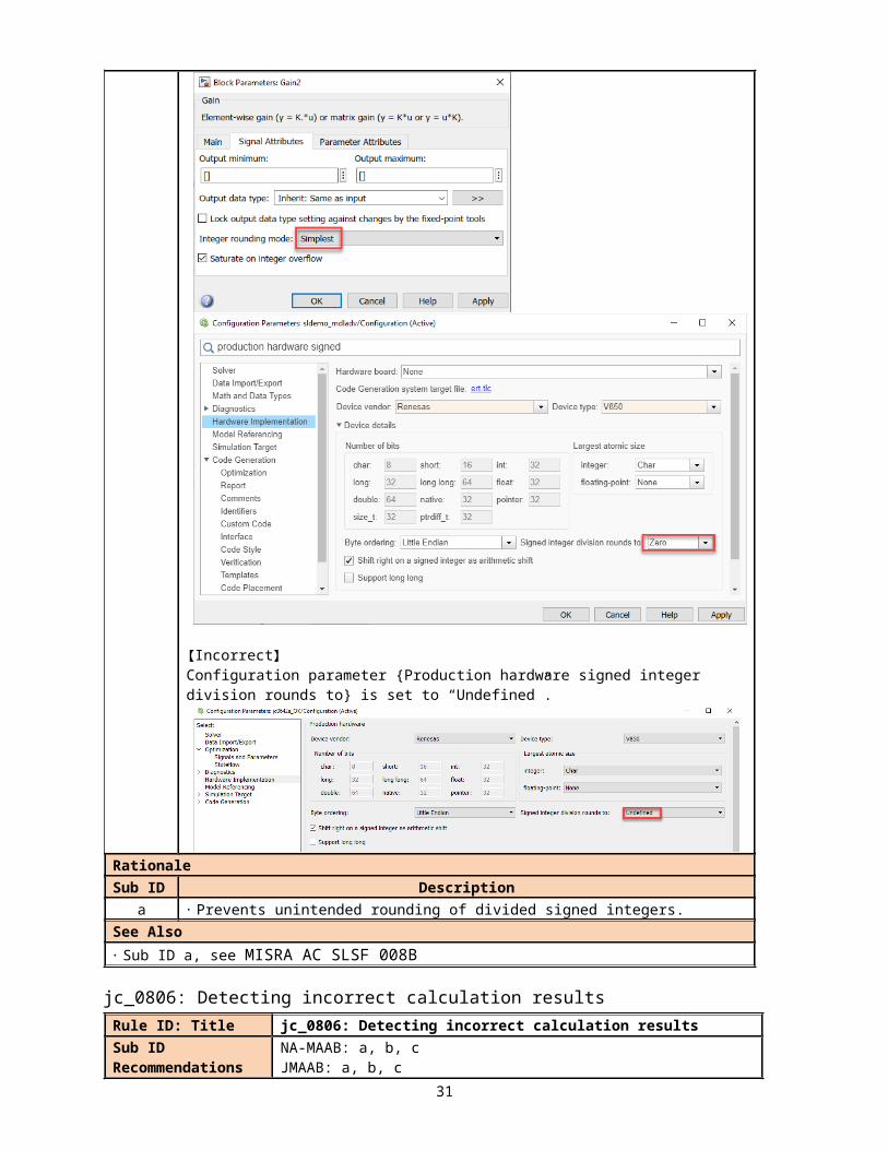
a When block signal attribute parameter {Integer rounding mode} is set to “Simplest”, configuration parameter {Production hardware signed integer division rounds to} shall be set to “Floor” or “Zero”.
-
【Correct】{Production hardware signed integer division rounds to} is set to “Zero”.
26
【Incorrect】Configuration parameter {Production hardware signed integer division rounds to} is set to “Undefined”.
RationaleSub ID Description
a Prevents unintended rounding of divided signed integers.See Also Sub ID a, see MISRA AC SLSF 008B
jc_0806: Detecting incorrect calculation resultsRule ID: Title jc_0806: Detecting incorrect calculation resultsSub ID Recommendations
NA-MAAB: a, b, cJMAAB: a, b, c
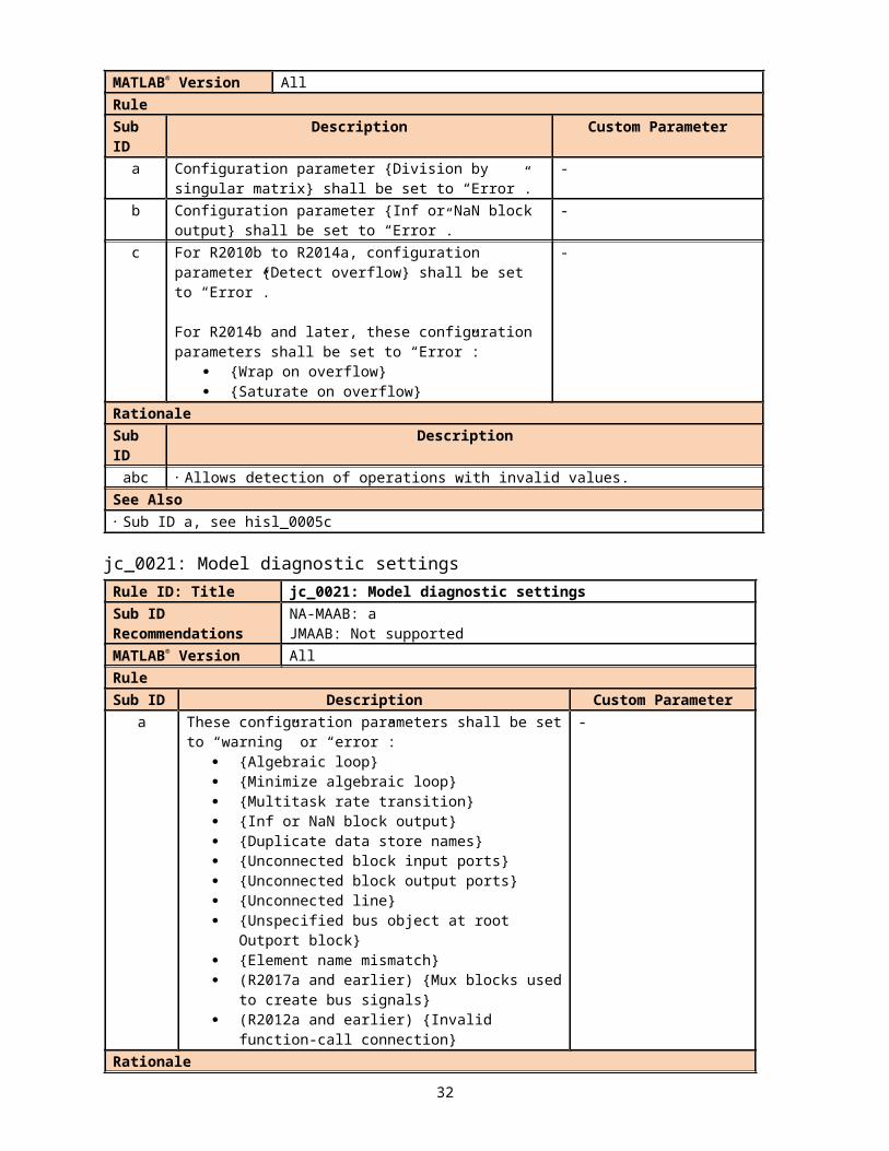
MATLAB® Version AllRuleSub ID Description Custom Parameter
a Configuration parameter {Division by singular matrix} shall be set to “Error”.
-
b Configuration parameter {Inf or NaN block output} shall be set to “Error”.
-
c For R2010b to R2014a, configuration parameter {Detect overflow} shall be set to “Error”.
For R2014b and later, these configuration parameters shall be set to “Error”:
{Wrap on overflow} {Saturate on overflow}
-
Rationale
27
Sub ID Descriptionabc Allows detection of operations with invalid values.
See Also Sub ID a, see hisl_0005c
jc_0021: Model diagnostic settingsRule ID: Title jc_0021: Model diagnostic settingsSub ID Recommendations
NA-MAAB: aJMAAB: Not supported
MATLAB® Version AllRuleSub ID Description Custom Parameter
a These configuration parameters shall be set to “warning” or “error”:
{Algebraic loop} {Minimize algebraic loop} {Multitask rate transition} {Inf or NaN block output} {Duplicate data store names} {Unconnected block input ports} {Unconnected block output ports} {Unconnected line} {Unspecified bus object at root Outport block} {Element name mismatch} (R2017a and earlier) {Mux blocks used to create
bus signals} (R2012a and earlier) {Invalid function-call
connection}
-
RationaleSub ID Description
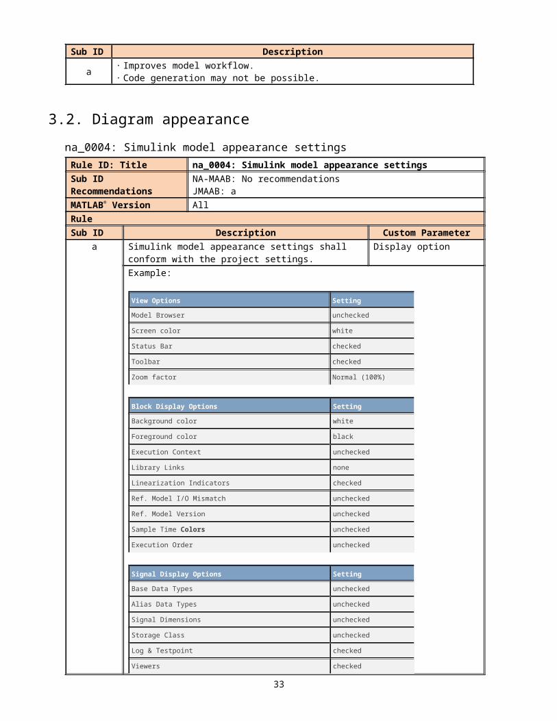
a Improves model workflow. Code generation may not be possible.
3.2. Diagram appearance
na_0004: Simulink model appearance settingsRule ID: Title na_0004: Simulink model appearance settingsSub ID Recommendations
NA-MAAB: No recommendationsJMAAB: a
MATLAB® Version AllRuleSub ID Description Custom Parameter
a Simulink model appearance settings shall conform with the project settings.
Display option
Example:
View Options Setting
Model Browser unchecked
Screen color white
Status Bar checked
Toolbar checked
28
Zoom factor Normal (100%)
Block Display Options Setting
Background color white
Foreground color black
Execution Context unchecked
Library Links none
Linearization Indicators checked
Ref. Model I/O Mismatch unchecked
Ref. Model Version unchecked
Sample Time Colors unchecked
Execution Order unchecked
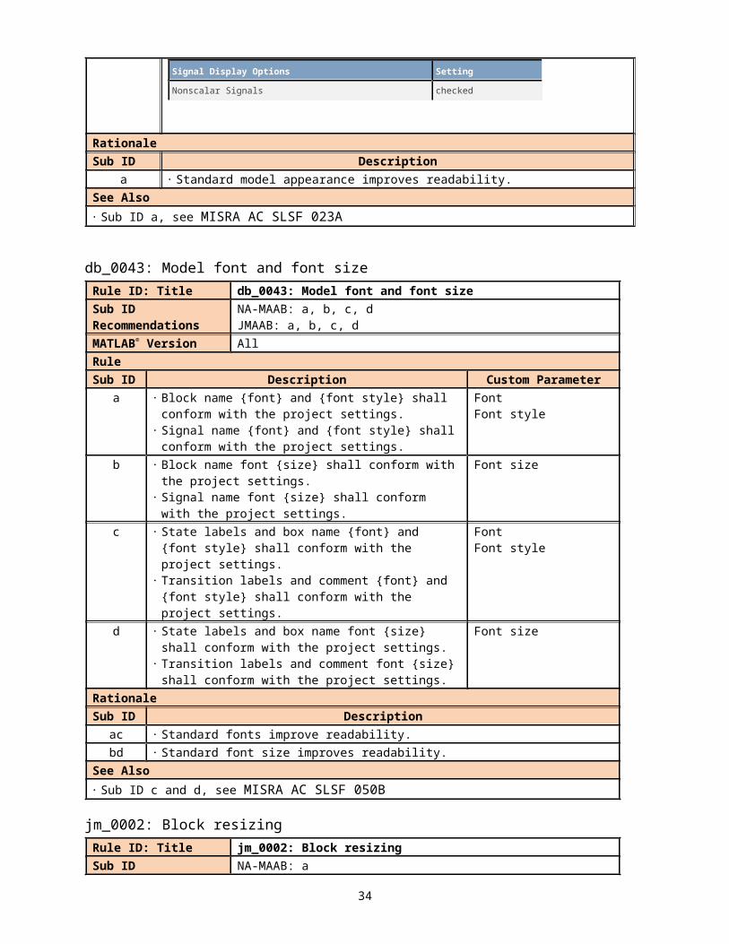
Signal Display Options Setting
Base Data Types unchecked
Alias Data Types unchecked
Signal Dimensions unchecked
Storage Class unchecked
Log & Testpoint checked
Viewers checked
Nonscalar Signals checked
RationaleSub ID Description
a Standard model appearance improves readability.See Also Sub ID a, see MISRA AC SLSF 023A
db_0043: Model font and font sizeRule ID: Title db_0043: Model font and font sizeSub ID Recommendations
NA-MAAB: a, b, c, dJMAAB: a, b, c, d
MATLAB® Version AllRuleSub ID Description Custom Parameter
a Block name {font} and {font style} shall conform with the project settings.
Signal name {font} and {font style} shall conform with the project settings.
FontFont style
b Block name font {size} shall conform with the project settings.
Signal name font {size} shall conform with the project settings.
Font size
c State labels and box name {font} and {font style} shall conform with the project settings.
Transition labels and comment {font} and {font style}
FontFont style
29
shall conform with the project settings.d State labels and box name font {size} shall conform with
the project settings. Transition labels and comment font {size} shall conform
with the project settings.
Font size
RationaleSub ID Description
ac Standard fonts improve readability.bd Standard font size improves readability.
See Also Sub ID c and d, see MISRA AC SLSF 050B
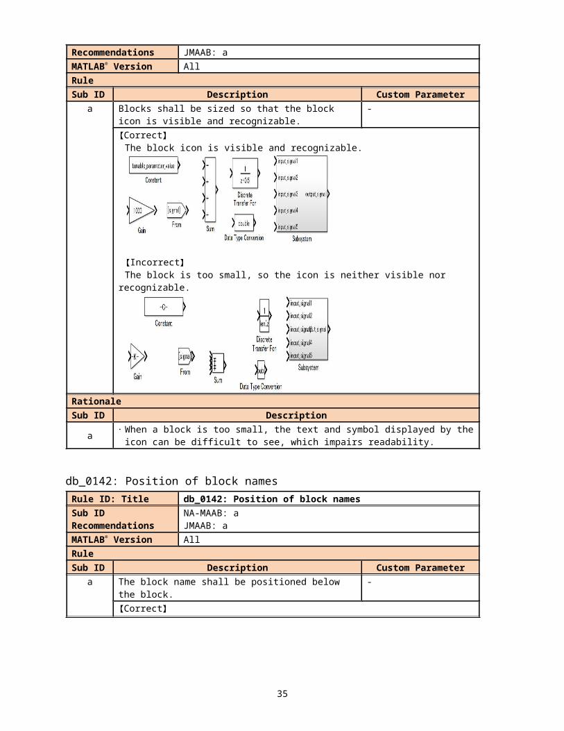
jm_0002: Block resizingRule ID: Title jm_0002: Block resizingSub ID Recommendations
NA-MAAB: aJMAAB: a
MATLAB® Version AllRuleSub ID Description Custom Parameter
a Blocks shall be sized so that the block icon is visible and recognizable.
-
【Correct】The block icon is visible and recognizable.
【Incorrect】The block is too small, so the icon is neither visible nor recognizable.
RationaleSub ID Description
a When a block is too small, the text and symbol displayed by the icon can be difficult to see, which impairs readability.
db_0142: Position of block namesRule ID: Title db_0142: Position of block namesSub ID Recommendations
NA-MAAB: aJMAAB: a
MATLAB® Version AllRule
30
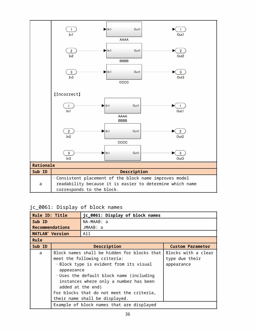
Sub ID Description Custom Parametera The block name shall be positioned below the block. -
【Correct】
【Incorrect】
RationaleSub ID Description
a Consistent placement of the block name improves model readability because it is easier to determine which name corresponds to the block.
jc_0061: Display of block namesRule ID: Title jc_0061: Display of block namesSub ID Recommendations
NA-MAAB: aJMAAB: a
MATLAB® Version AllRuleSub ID Description Custom Parameter
a Block names shall be hidden for blocks that meet the following criteria: Block type is evident from its visual appearance Uses the default block name (including instances
where only a number has been added at the end)For blocks that do not meet the criteria, their name shall be displayed.
Blocks with a clear type due their appearance
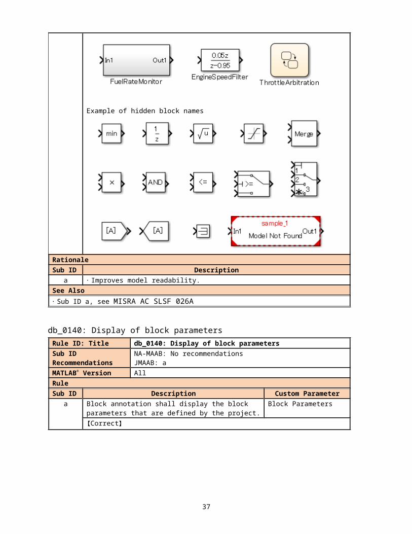
Example of block names that are displayed
31
Example of hidden block names
RationaleSub ID Description
a Improves model readability.See Also Sub ID a, see MISRA AC SLSF 026A
db_0140: Display of block parametersRule ID: Title db_0140: Display of block parametersSub ID Recommendations
NA-MAAB: No recommendationsJMAAB: a
MATLAB® Version AllRuleSub ID Description Custom Parameter
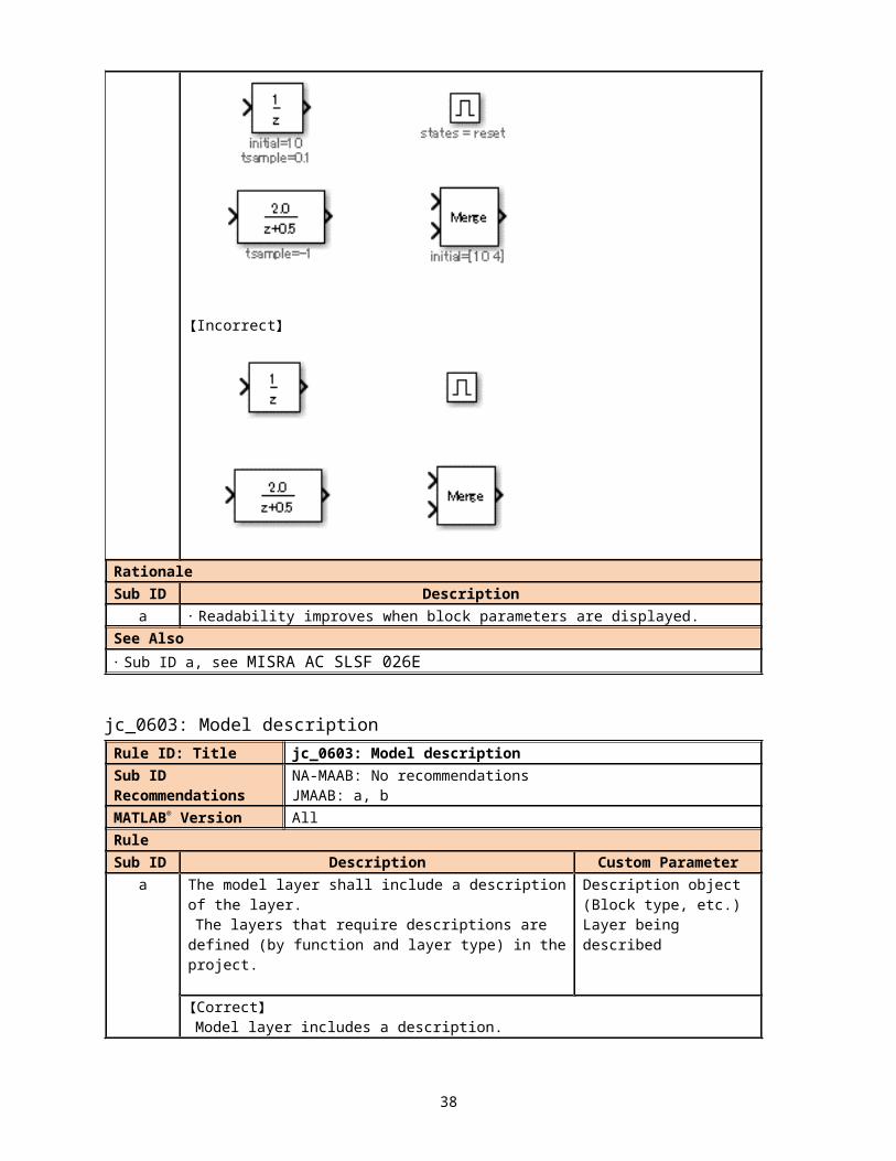
a Block annotation shall display the block parameters that are defined by the project.
Block Parameters
【Correct】
32
【Incorrect】
RationaleSub ID Description
a Readability improves when block parameters are displayed.See Also Sub ID a, see MISRA AC SLSF 026E
jc_0603: Model descriptionRule ID: Title jc_0603: Model descriptionSub ID Recommendations
NA-MAAB: No recommendationsJMAAB: a, b
MATLAB® Version AllRuleSub ID Description Custom Parameter
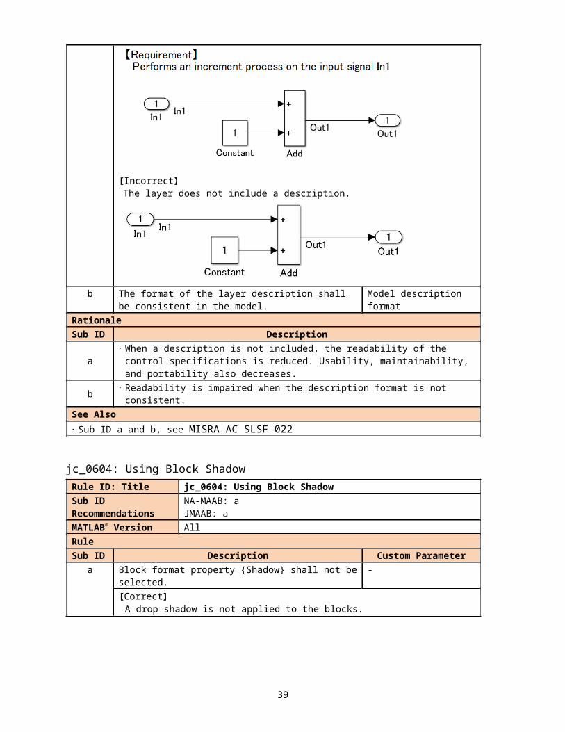
a The model layer shall include a description of the layer.The layers that require descriptions are defined (by
function and layer type) in the project.
Description object(Block type, etc.)Layer being described
【Correct】Model layer includes a description.
33
【Incorrect】The layer does not include a description.
b The format of the layer description shall be consistent in the model.
Model description format
RationaleSub ID Description
a When a description is not included, the readability of the control specifications is reduced. Usability, maintainability, and portability also decreases.
b Readability is impaired when the description format is not consistent.See Also Sub ID a and b, see MISRA AC SLSF 022
jc_0604: Using Block ShadowRule ID: Title jc_0604: Using Block ShadowSub ID Recommendations
NA-MAAB: aJMAAB: a
MATLAB® Version AllRuleSub ID Description Custom Parameter
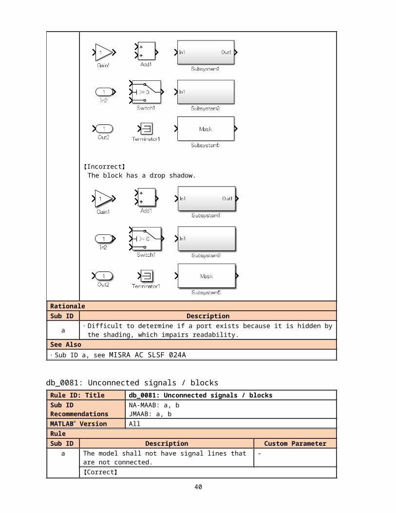
a Block format property {Shadow} shall not be selected. -【Correct】
A drop shadow is not applied to the blocks.
34
【Incorrect】The block has a drop shadow.
RationaleSub ID Description
a Difficult to determine if a port exists because it is hidden by the shading, which impairs readability.
See Also Sub ID a, see MISRA AC SLSF 024A
db_0081: Unconnected signals / blocksRule ID: Title db_0081: Unconnected signals / blocksSub ID Recommendations
NA-MAAB: a, bJMAAB: a, b
MATLAB® Version AllRuleSub ID Description Custom Parameter
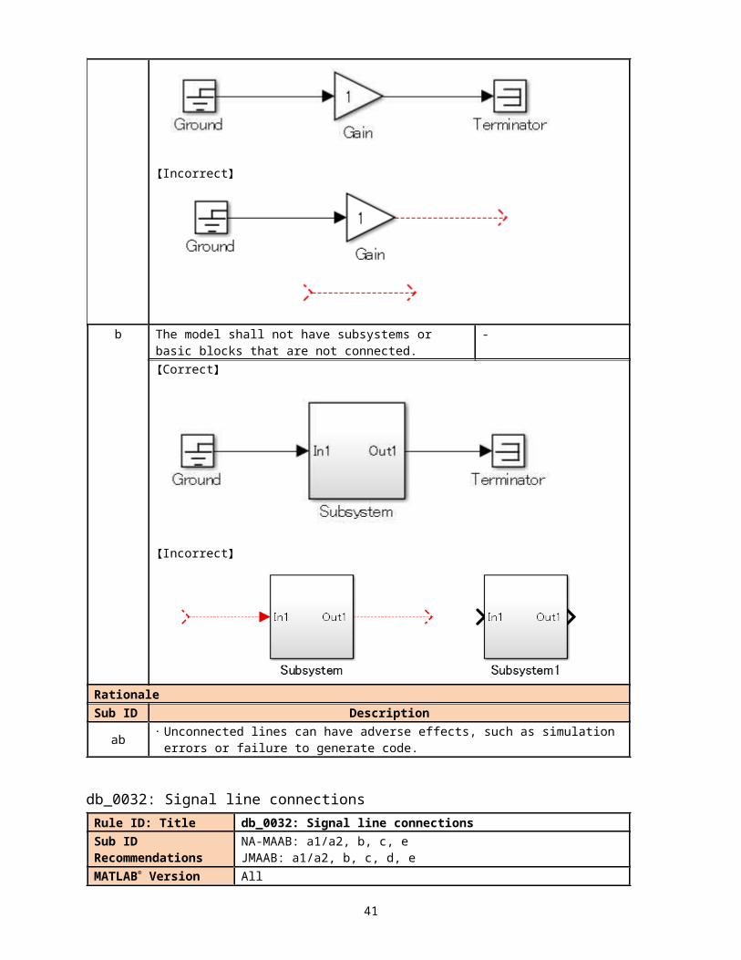
a The model shall not have signal lines that are not connected.
-
【Correct】
35
【Incorrect】
b The model shall not have subsystems or basic blocks that are not connected.
-
【Correct】
【Incorrect】
RationaleSub ID Description
ab Unconnected lines can have adverse effects, such as simulation errors or failure to generate code.
db_0032: Signal line connectionsRule ID: Title db_0032: Signal line connectionsSub ID Recommendations
NA-MAAB: a1/a2, b, c, eJMAAB: a1/a2, b, c, d, e
MATLAB® Version AllRuleSub ID Description Custom Parameter
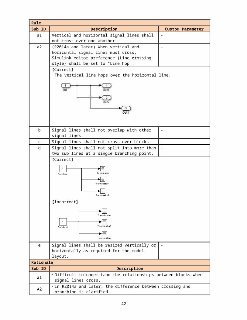
a1 Vertical and horizontal signal lines shall not cross over -
36
one another.a2 (R2014a and later) When vertical and horizontal signal
lines must cross, Simulink editor preference {Line crossing style} shall be set to “Line hop”.
-
【Correct】The vertical line hops over the horizontal line.
b Signal lines shall not overlap with other signal lines. -c Signal lines shall not cross over blocks. -d Signal lines shall not split into more than two sub lines at
a single branching point.-
【Correct】
【Incorrect】
e Signal lines shall be resized vertically or horizontally as required for the model layout.
-
RationaleSub ID Description
a1 Difficult to understand the relationships between blocks when signal lines cross.A2 In R2014a and later, the difference between crossing and branching is clarified.B Difficult to understand the relationships between blocks when signal lines overlap..C Difficult to understand the relationships between blocks when signal lines cross.D Difficult to understand the relationships between blocks.E Consistent application of signal lines improves readability.
db_0141: Signal flow in Simulink modelsRule ID: Title db_0141: Signal flow in Simulink modelsSub ID Recommendations
NA-MAAB: No recommendationsJMAAB: a, b, c
MATLAB® Version AllRule
37
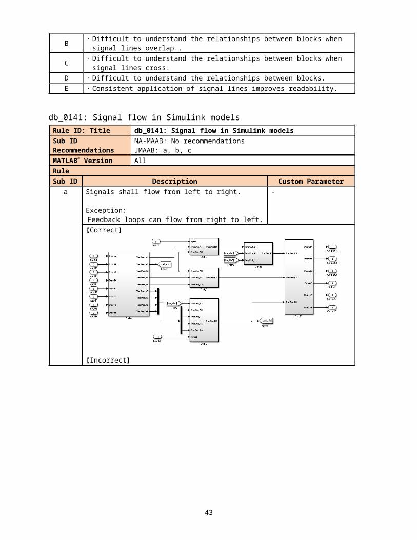
Sub ID Description Custom Parametera Signals shall flow from left to right.
Exception:Feedback loops can flow from right to left.
-
【Correct】
【Incorrect】
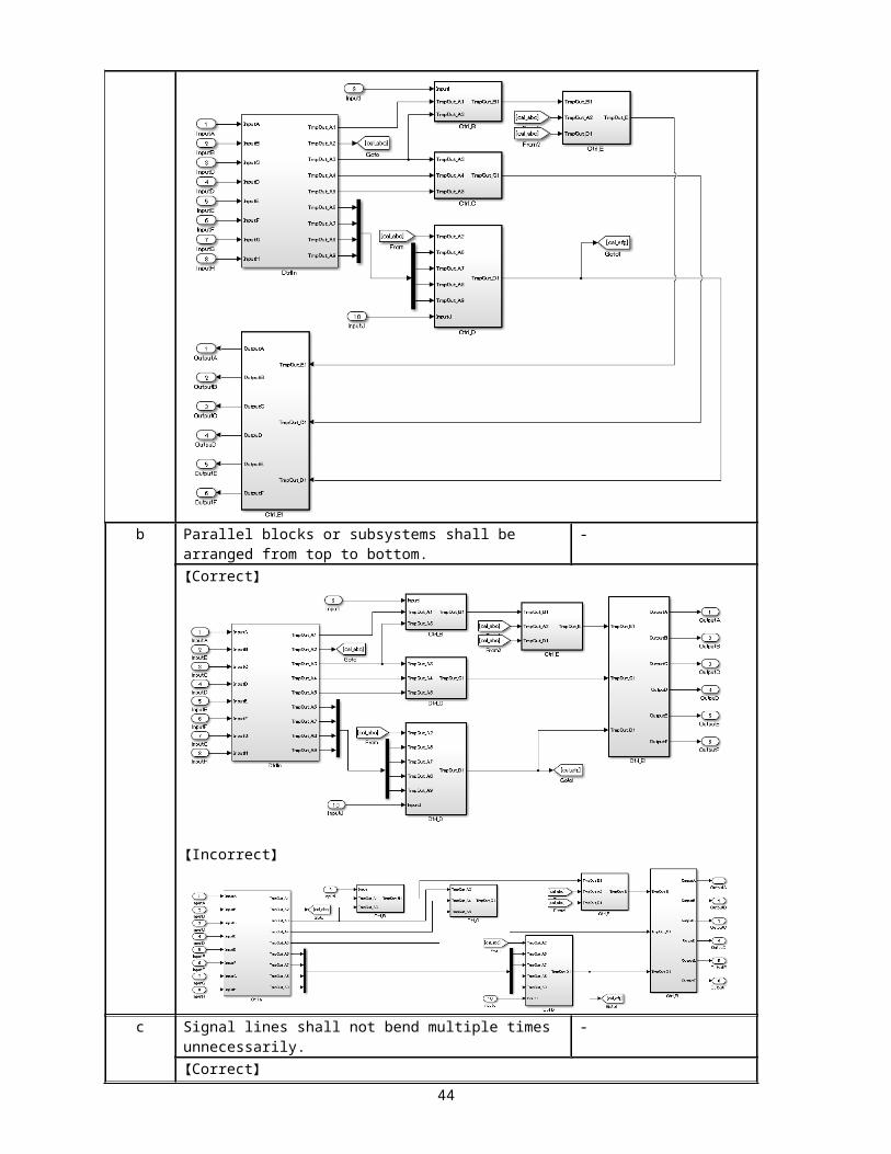
b Parallel blocks or subsystems shall be arranged from top to bottom.
-
【Correct】
38
【Incorrect】
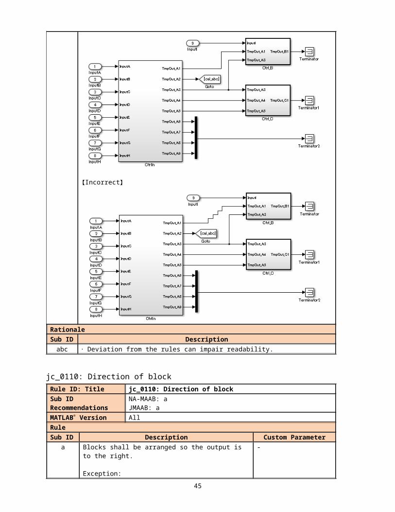
c Signal lines shall not bend multiple times unnecessarily. -【Correct】
【Incorrect】
39
RationaleSub ID Description
abc Deviation from the rules can impair readability.
jc_0110: Direction of blockRule ID: Title jc_0110: Direction of blockSub ID Recommendations
NA-MAAB: aJMAAB: a
MATLAB® Version AllRuleSub ID Description Custom Parameter
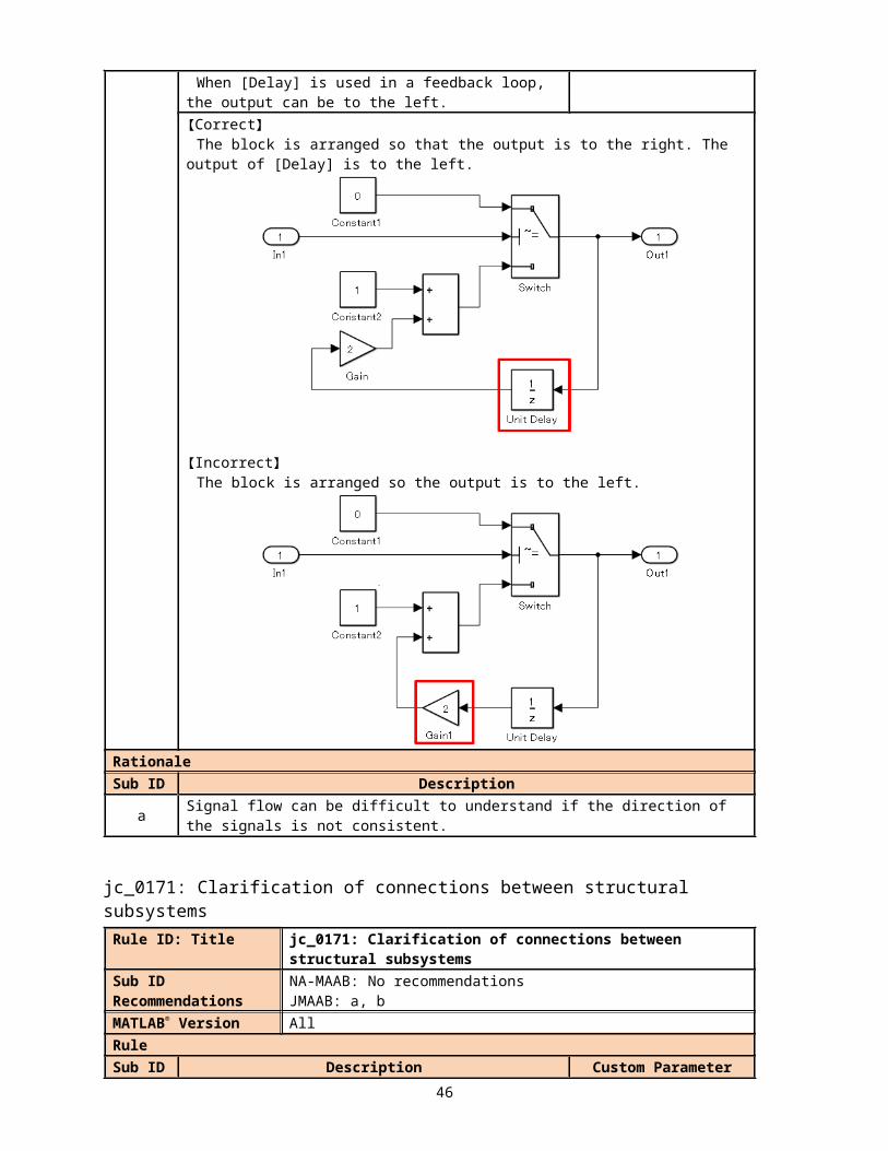
a Blocks shall be arranged so the output is to the right.
Exception:When [Delay] is used in a feedback loop, the output can
be to the left.
-
【Correct】The block is arranged so that the output is to the right. The output of [Delay] is to the
left.
【Incorrect】The block is arranged so the output is to the left.
40
RationaleSub ID Description
a Signal flow can be difficult to understand if the direction of the signals is not consistent.
jc_0171: Clarification of connections between structural subsystemsRule ID: Title jc_0171: Clarification of connections between structural
subsystemsSub ID Recommendations
NA-MAAB: No recommendationsJMAAB: a, b
MATLAB® Version AllRuleSub ID Description Custom Parameter
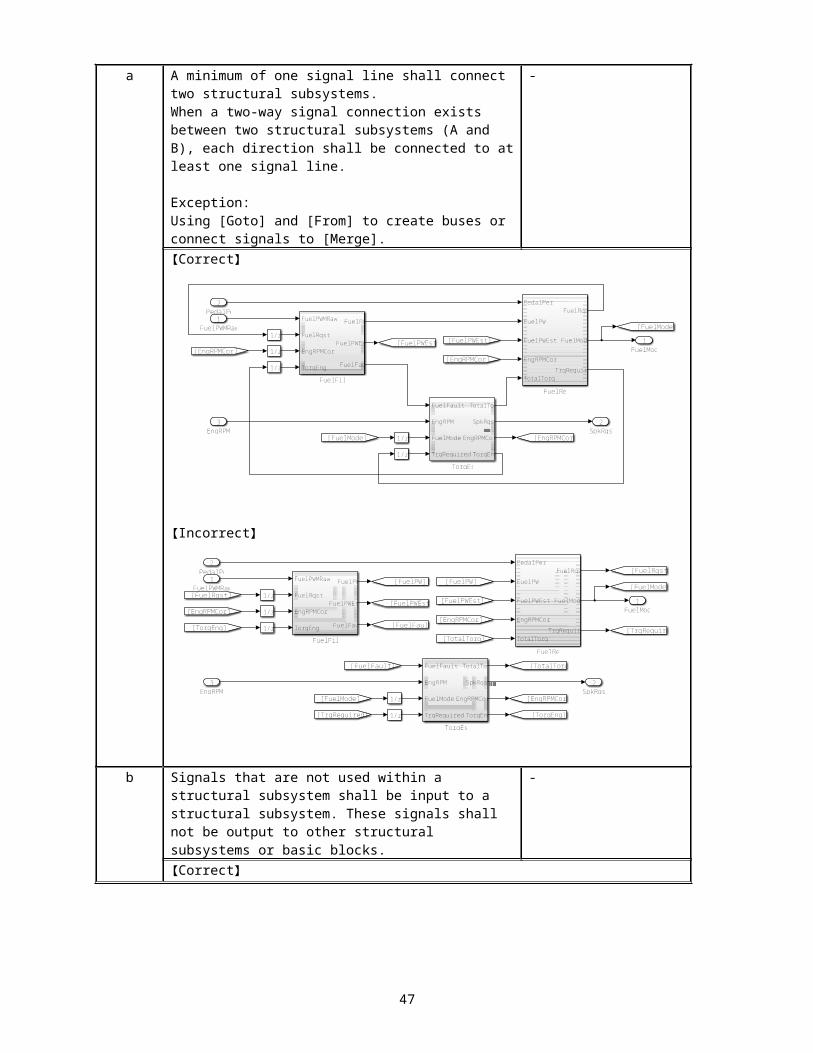
a A minimum of one signal line shall connect two structural subsystems.When a two-way signal connection exists between two structural subsystems (A and B), each direction shall be connected to at least one signal line.
Exception:Using [Goto] and [From] to create buses or connect signals to [Merge].
-
41
【Correct】
FuelPWMRaw
FuelRqst
EngRPMCor
TorqEng
FuelPW
FuelPWEst
FuelFault
FuelFilter
PedalPer
FuelPW
FuelPWEst
EngRPMCor
TotalTorq
FuelRqst
FuelMode
TrqRequired
FuelReq
FuelFault
EngRPM
FuelMode
TrqRequired
TotalTorq
SpkRqst
EngRPMCor
TorqEng
TorqEst
1FuelPWMRaw
2PedalPer
3EngRPM
1FuelMode
2SpkRqst
[FuelMode]
[FuelPWEst]
[EngRPMCor]
[EngRPMCor]
1/z
1/z
1/z
1/z
[EngRPMCor]
[FuelPWEst]
[FuelMode]1/z
【Incorrect】
FuelPWMRaw
FuelRqst
EngRPMCor
TorqEng
FuelPW
FuelPWEst
FuelFault
FuelFilter
PedalPer
FuelPW
FuelPWEst
EngRPMCor
TotalTorq
FuelRqst
FuelMode
TrqRequired
FuelReq
FuelFault
EngRPM
FuelMode
TrqRequired
TotalTorq
SpkRqst
EngRPMCor
TorqEng
TorqEst
1FuelPWMRaw
2PedalPer
3EngRPM
1FuelMode
2SpkRqst
[FuelMode]
[FuelPWEst]
[EngRPMCor]
[EngRPMCor]
1/z
1/z
1/z
1/z
[EngRPMCor]
[FuelPWEst]
[FuelMode][FuelPW] [FuelPW]
[FuelFault]
[FuelRqst]
[TrqRequired]
[FuelFault]
[TorqEng]
[TorqEng][TrqRequired]
[FuelRqst] 1/z
[TotalTorq]
[TotalTorq]
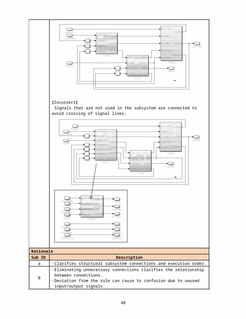
b Signals that are not used within a structural subsystem shall be input to a structural subsystem. These signals shall not be output to other structural subsystems or basic blocks.
-
【Correct】
FuelPWMRaw
FuelRqst
EngRPMCor
TorqEng
FuelPW
FuelPWEst
FuelFault
FuelFilter
PedalPer
FuelPW
FuelPWEst
TotalTorq
EngRPMCor
FuelRqst
FuelMode
TrqRequired
FuelReq
FuelFault
EngRPM
FuelMode
TrqRequired
TotalTorq
EngRPMCor
SpkRqst
TorqEng
TorqEst
1FuelPWMRaw
2PedalPer
3EngRPM
1FuelMode
2SpkRqst
1/z
1/z
1/z
1/z
1/z
【Incorrect】Signals that are not used in the subsystem are connected to avoid crossing of signal
lines.
42
FuelPWMRaw
FuelRqst
EngRPM_in
FuelMode_in
TrqRequired_in
EngRPMCor
TorqEng
FuelPW
FuelPWEst
FuelFault
EngRPM
FuelMode
TrqRequired
FuelFilter
PedalPer
FuelPW
FuelPWEst
TotalTorq
EngRPMCor
FuelRqst
FuelMode
TrqRequired
FuelReqFuelFault
EngRPM
FuelMode
TrqRequired
TotalTorq
EngRPMCor
SpkRqst
TorqEng
TorqEst
1FuelPWMRaw
2PedalPer
3EngRPM
1FuelMode
2SpkRqst
1/z
1/z
1/z
1/z
1/z
1FuelPWMRaw
2FuelRqst
6EngRPMCor
7TorqEng
1FuelPW
2FuelPWEst
3FuelFault
FuelPWMRaw
FuelRqst
EngRPMCor
TorqEng
FuelPW
FuelPWEst
FuelFault
FuelFilter
3EngRPM_in
4FuelMode_in
5TrqRequired_in
4EngRPM
5FuelMode
6TrqRequired
RationaleSub ID Description
a Clarifies structural subsystem connections and execution order.
B Eliminating unnecessary connections clarifies the relationship between connections. Deviation from the rule can cause to confusion due to unused input/output signals.
jc_0602: Consistency in model element namesRule ID: Title jc_0602: Consistency in model element namesSub ID Recommendations
NA-MAAB: No recommendationsJMAAB: a
MATLAB® Version AllRuleSub ID Description Custom Parameter
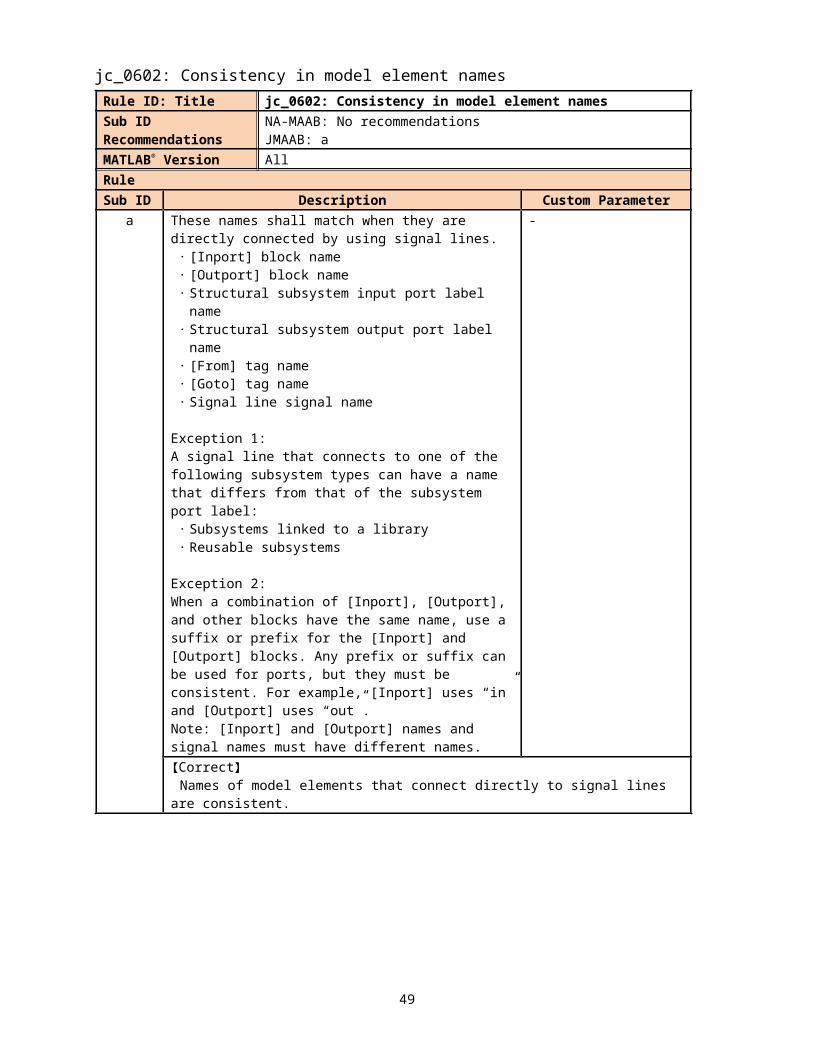
a These names shall match when they are directly connected by using signal lines. [Inport] block name [Outport] block name Structural subsystem input port label name Structural subsystem output port label name [From] tag name [Goto] tag name Signal line signal name
Exception 1:A signal line that connects to one of the following subsystem types can have a name that differs from that of the subsystem port label: Subsystems linked to a library
-
43
Reusable subsystems
Exception 2:When a combination of [Inport], [Outport], and other blocks have the same name, use a suffix or prefix for the [Inport] and [Outport] blocks. Any prefix or suffix can be used for ports, but they must be consistent. For example, [Inport] uses “in” and [Outport] uses “out”. Note: [Inport] and [Outport] names and signal names must have different names.【Correct】
Names of model elements that connect directly to signal lines are consistent.
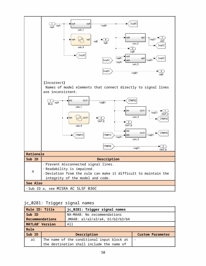
【Incorrect】Names of model elements that connect directly to signal lines are inconsistent.
RationaleSub ID Description
a
Prevent misconnected signal lines. Readability is impaired. Deviation from the rule can make it difficult to maintain the integrity of the model and
code.See Also Sub ID a, see MISRA AC SLSF 036C
jc_0281: Trigger signal namesRule ID: Title jc_0281: Trigger signal namesSub ID NA-MAAB: No recommendations
44
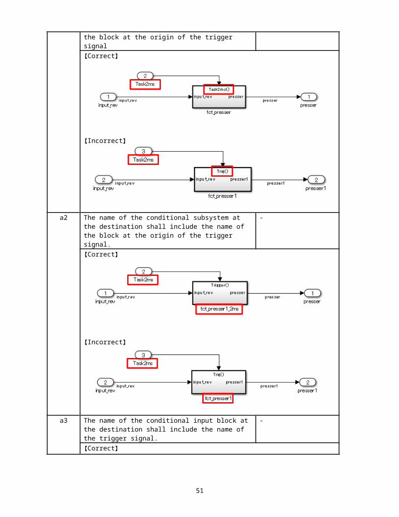
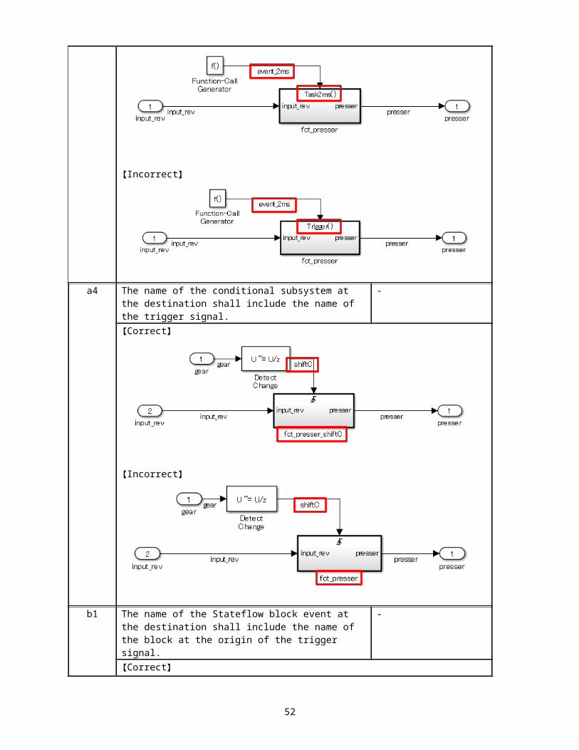
Recommendations JMAAB: a1/a2/a3/a4, b1/b2/b3/b4MATLAB® Version AllRuleSub ID Description Custom Parameter
a1 The name of the conditional input block at the destination shall include the name of the block at the origin of the trigger signal
-
【Correct】
【Incorrect】
a2 The name of the conditional subsystem at the destination shall include the name of the block at the origin of the trigger signal.
-
【Correct】
【Incorrect】
a3 The name of the conditional input block at the destination shall include the name of the trigger signal.
-
【Correct】
45
【Incorrect】
a4 The name of the conditional subsystem at the destination shall include the name of the trigger signal.
-
【Correct】
【Incorrect】
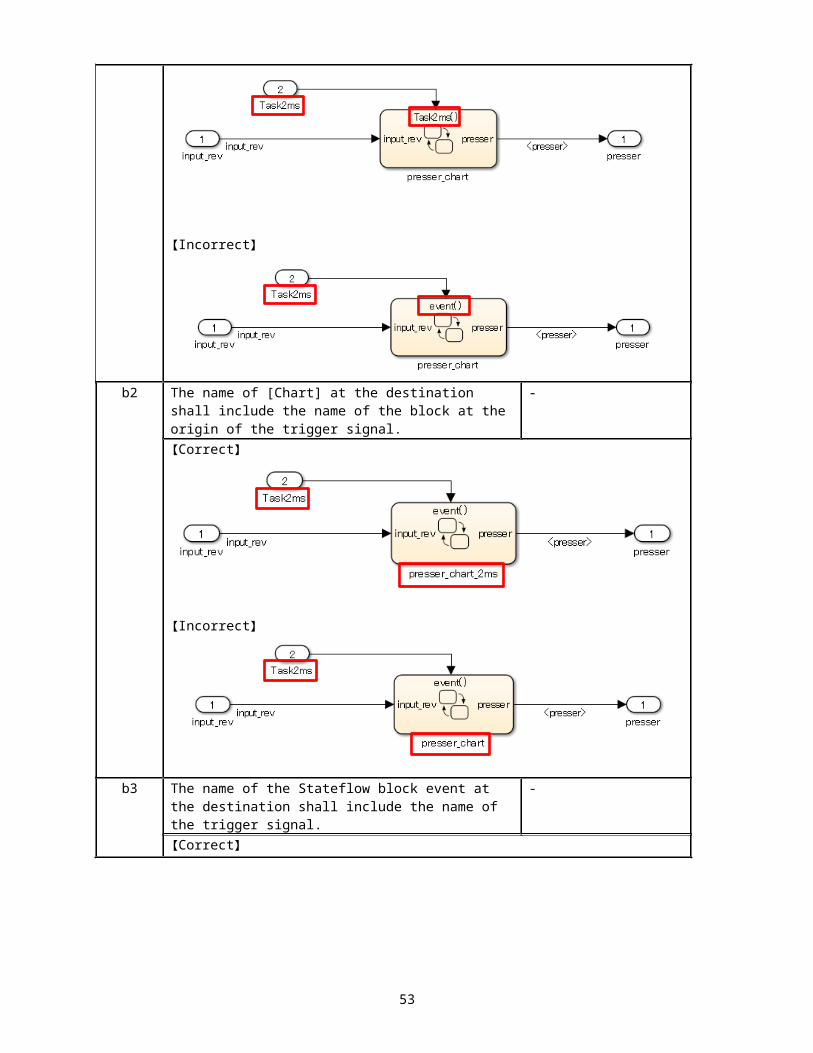
b1 The name of the Stateflow block event at the destination shall include the name of the block at the origin of the trigger signal.
-
【Correct】
46
【Incorrect】
b2 The name of [Chart] at the destination shall include the name of the block at the origin of the trigger signal.
-
【Correct】
【Incorrect】
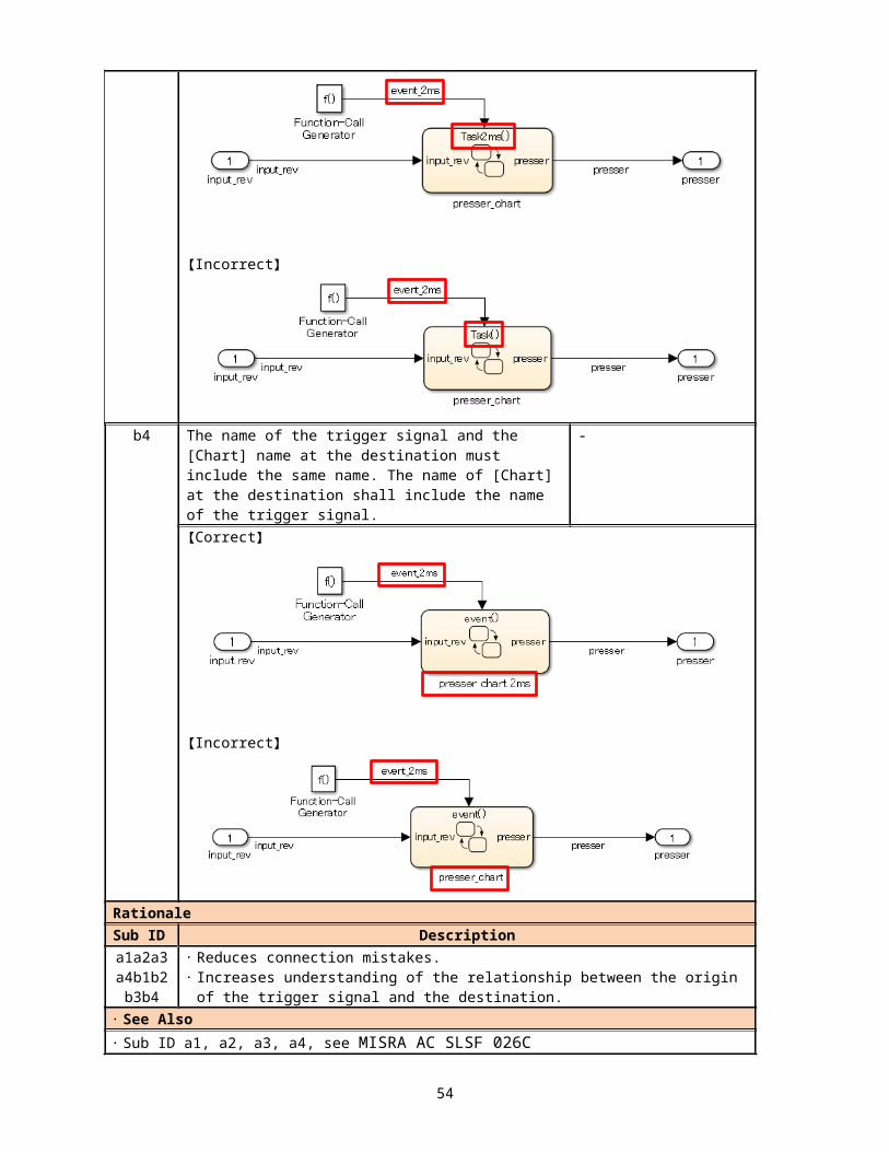
b3 The name of the Stateflow block event at the destination shall include the name of the trigger signal.
-
【Correct】
【Incorrect】
47
b4 The name of the trigger signal and the [Chart] name at the destination must include the same name. The name of [Chart] at the destination shall include the name of the trigger signal.
-
【Correct】
【Incorrect】
RationaleSub ID Descriptiona1a2a3a4b1b2b3
b4
Reduces connection mistakes. Increases understanding of the relationship between the origin of the trigger signal
and the destination. See Also Sub ID a1, a2, a3, a4, see MISRA AC SLSF 026C
db_0143: Usable block types in model hierarchyRule ID: Title db_0143: Usable block types in model hierarchySub ID Recommendations
NA-MAAB: aJMAAB: a
MATLAB® Version AllRuleSub ID Description Custom Parameter
a Model levels shall use only the block types that are defined for the layer type.
For information on layer types, see Appendix 8.2 - Hierarchical Structure of a Controller Model. Clearly defined layer types restrict the number of blocks that can
Layer typeBlock type
48
be used.
Block restrictions: (R2011a and earlier) [Enable] cannot be used at the
root level of the model. Action ports are not permitted at the root level of a
model.Layer restrictions: Data flow layers that are used for basic blocks only. Other than data flow layers, layers can include blocks that are used for structural
subsystems and all other layers.
Blocks that can be used for all layers include: [Inport] [Outport] [Mux] [Demux] [Bus Selector] [Bus Creator] [Selector] [Ground] [Terminator] [From] [Goto] [Merge] [Unit Delay] [Rate Transition] [Data Type Conversion] [Data Store Memory] [If] [Switch Case] [Function-Call Generator] [Function-Call Split]
RationaleSub ID Description
a Readability is impaired when subsystems and basic blocks are used in the same layer.
db_0144: Use of subsystemsRule ID: Title db_0144: Use of subsystemsSub ID Recommendations
NA-MAAB: a, bJMAAB: a, b
MATLAB® Version AllRuleSub ID Description Custom Parameter
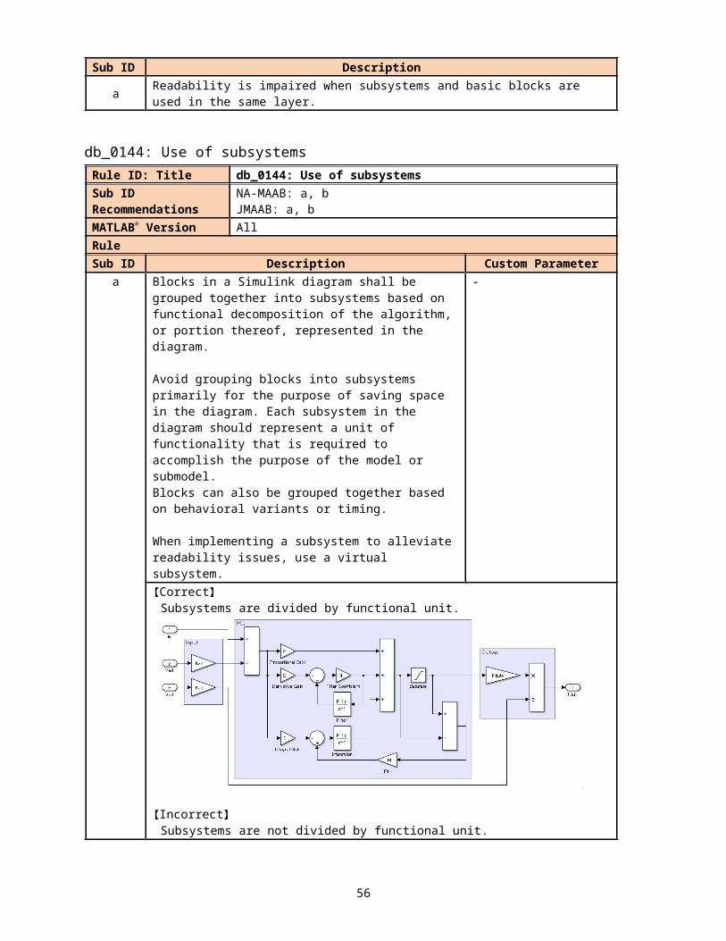
a Blocks in a Simulink diagram shall be grouped together into subsystems based on functional decomposition of the algorithm, or portion thereof, represented in the diagram.
Avoid grouping blocks into subsystems primarily for the purpose of saving space in the diagram. Each subsystem in the diagram should represent a unit of functionality that is required to accomplish the purpose of the model or submodel. Blocks can also be grouped together based on behavioral variants or timing.
-
49
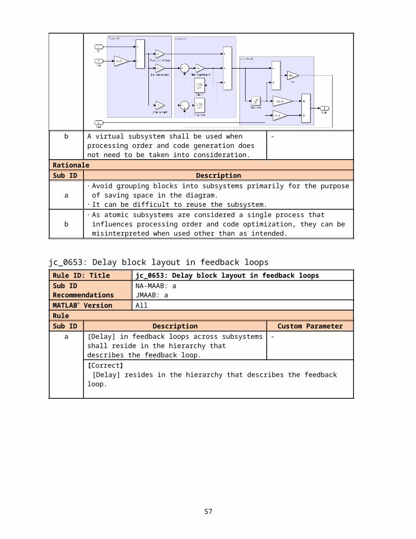
When implementing a subsystem to alleviate readability issues, use a virtual subsystem.【Correct】
Subsystems are divided by functional unit.
【Incorrect】Subsystems are not divided by functional unit.
b A virtual subsystem shall be used when processing order and code generation does not need to be taken into consideration.
-
RationaleSub ID Description
a Avoid grouping blocks into subsystems primarily for the purpose of saving space in
the diagram. It can be difficult to reuse the subsystem.
b As atomic subsystems are considered a single process that influences processing
order and code optimization, they can be misinterpreted when used other than as intended.
jc_0653: Delay block layout in feedback loopsRule ID: Title jc_0653: Delay block layout in feedback loopsSub ID Recommendations
NA-MAAB: aJMAAB: a
MATLAB® Version AllRuleSub ID Description Custom Parameter
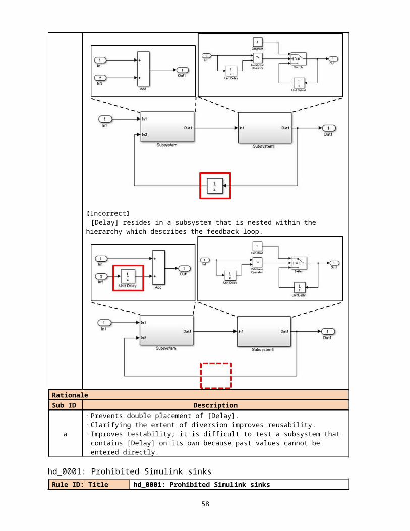
a [Delay] in feedback loops across subsystems shall reside in the hierarchy that describes the feedback loop.
-
【Correct】[Delay] resides in the hierarchy that describes the feedback loop.
50
【Incorrect】[Delay] resides in a subsystem that is nested within the hierarchy which describes the
feedback loop.
RationaleSub ID Description
a
Prevents double placement of [Delay]. Clarifying the extent of diversion improves reusability. Improves testability; it is difficult to test a subsystem that contains [Delay] on its own
because past values cannot be entered directly.
hd_0001: Prohibited Simulink sinksRule ID: Title hd_0001: Prohibited Simulink sinksSub ID Recommendations
NA-MAAB: aJMAAB: Not supported
MATLAB® Version AllRule
51
Sub ID Description Custom Parametera Control algorithm models shall be designed from discrete
blocks. [Scope] and [Display] can be used in the model diagram. These sink blocks shall not be used:
[To File] [To Workspace] [Stop Simulation]
Consider using signal logging and the Signal and Scope Manager for data logging and viewing requirements. (R2019b and later) To log and manage the signal, click the Simulation tab and, under the Prepare gallery, select the appropriate tool.
-
RationaleSub ID Description
a Improves readability and model simulation. Code generation may not be possible.
3.3. Signal
na_0010: Usage of vector and bus signalsRule ID: Title na_0010: Usage of vector and bus signalsSub ID Recommendations
NA-MAAB: a, b, c, dJMAAB: a, b, c, d
MATLAB® Version AllRuleSub ID Description Custom Parameter
a [Mux] and [Demux] blocks shall be used when generating and decomposing vectors.
-
b [Mux] inputs shall be scalars and vectors. -c [BusCreator] and [BusSelector] shall be used when
generating and decomposing busses.-
d Busses shall connect to blocks that support busses. -RationaleSub ID Description
abcd Prevents issues that are caused by combining vector and bus signals.See “Preventing the mixing of busses and Mux” for additional information.
See Also Sub ID a, b, c, d, see MISRA AC SLSF 015A,B
jc_0008: Definition of signal namesRule ID: Title jc_0008: Definition of signal namesSub ID Recommendations
NA-MAAB: No recommendationsJMAAB: a
MATLAB® Version AllRuleSub ID Description Custom Parameter
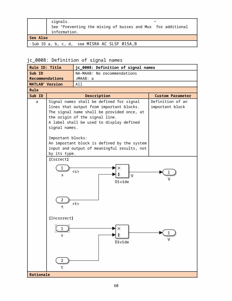
a Signal names shall be defined for signal lines that output from important blocks. The signal name shall be provided once, at the origin of the signal line.A label shall be used to display defined signal names.
Definition of an important block
52
Important blocks:An important block is defined by the system input and output of meaningful results, not by its type.【Correct】
【Incorrect】
RationaleSub ID Description
a Defining the signal name and displaying the label for the output of meaningful results from important blocks improves the readability of the model.
jc_0009: Signal name propagationRule ID: Title jc_0009: Signal name propagationSub ID Recommendations
NA-MAAB: No recommendationsJMAAB: a, b
MATLAB® Version AllRuleSub ID
Description Custom Parameter
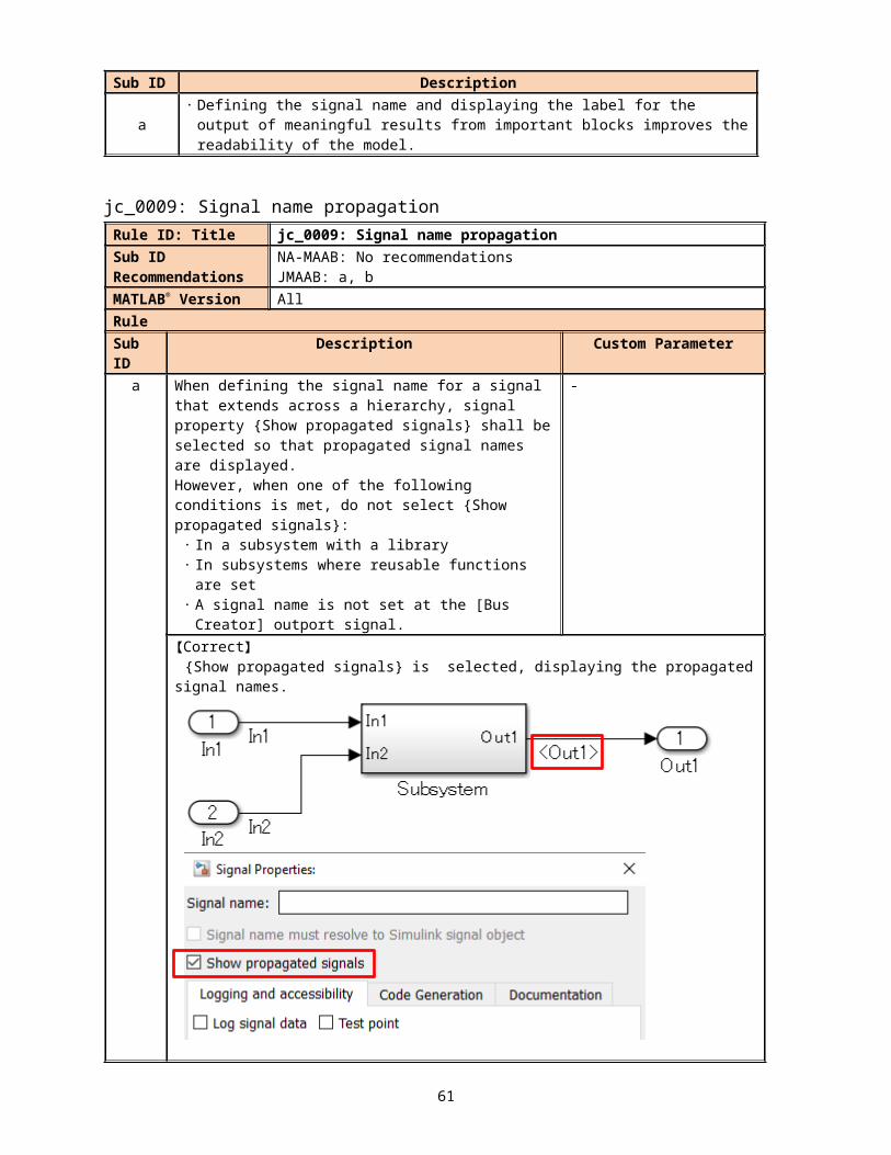
a When defining the signal name for a signal that extends across a hierarchy, signal property {Show propagated signals} shall be selected so that propagated signal names are displayed.However, when one of the following conditions is met, do not select {Show propagated signals}: In a subsystem with a library In subsystems where reusable functions are set A signal name is not set at the [Bus Creator] outport
signal.
-
【Correct】{Show propagated signals} is selected, displaying the propagated signal names.
53
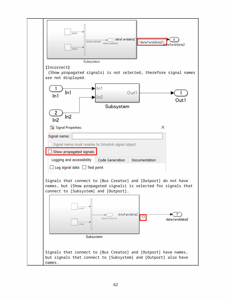
【Incorrect】{Show propagated signals} is not selected, therefore signal names are not displayed.
Signals that connect to [Bus Creator] and [Outport] do not have names, but {Show propagated signals} is selected for signals that connect to [Subsystem] and [Outport].
54
Signals that connect to [Bus Creator] and [Outport] have names, but signals that connect to [Subsystem] and [Outport] also have names.
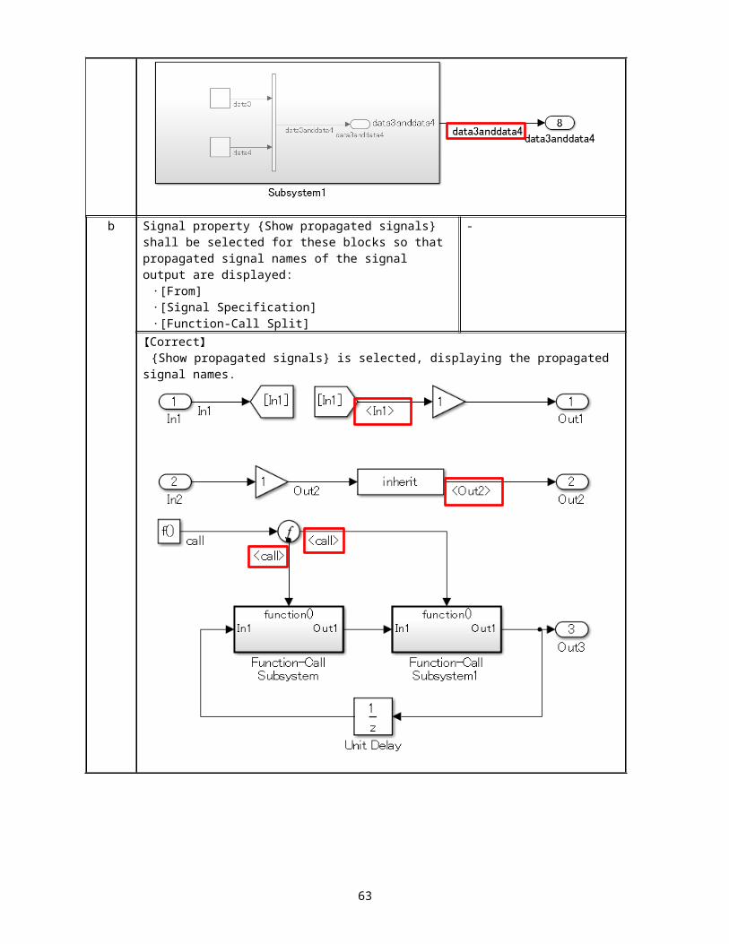
b Signal property {Show propagated signals} shall be selected for these blocks so that propagated signal names of the signal output are displayed:
[From] [Signal Specification] [Function-Call Split]
-
【Correct】{Show propagated signals} is selected, displaying the propagated signal names.
55
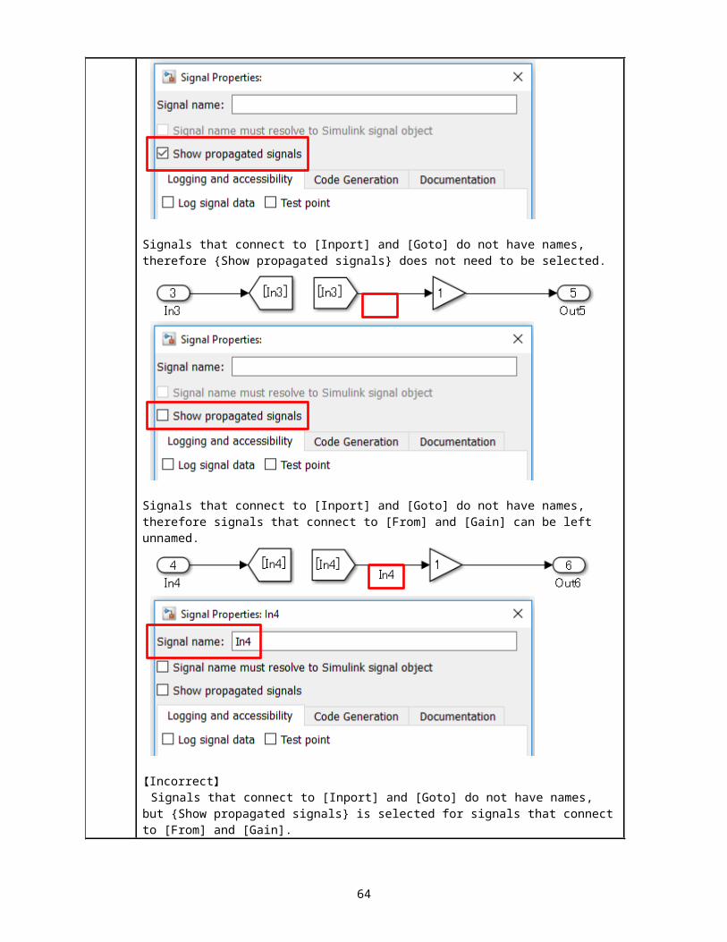
Signals that connect to [Inport] and [Goto] do not have names, therefore {Show propagated signals} does not need to be selected.
Signals that connect to [Inport] and [Goto] do not have names, therefore signals that connect to [From] and [Gain] can be left unnamed.
56
【Incorrect】Signals that connect to [Inport] and [Goto] do not have names, but {Show propagated
signals} is selected for signals that connect to [From] and [Gain].
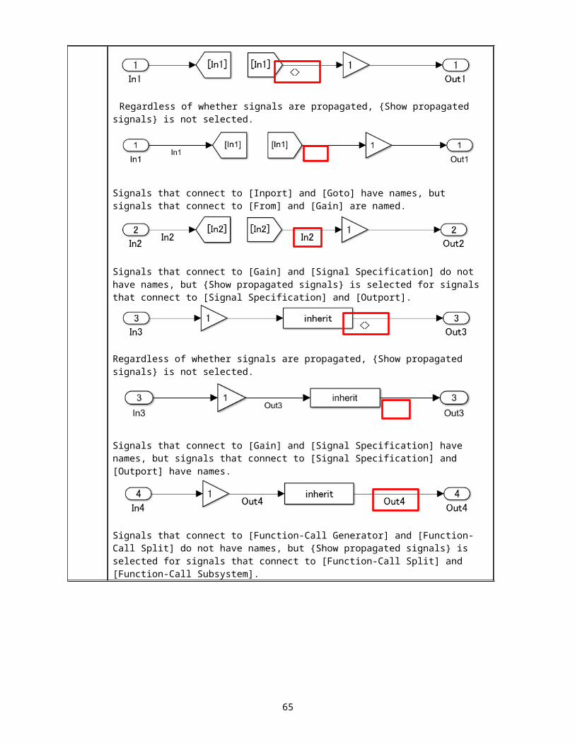
Regardless of whether signals are propagated, {Show propagated signals} is not selected.
Signals that connect to [Inport] and [Goto] have names, but signals that connect to [From] and [Gain] are named.
Signals that connect to [Gain] and [Signal Specification] do not have names, but {Show propagated signals} is selected for signals that connect to [Signal Specification] and [Outport].
Regardless of whether signals are propagated, {Show propagated signals} is not selected.
Signals that connect to [Gain] and [Signal Specification] have names, but signals that connect to [Signal Specification] and [Outport] have names.
Signals that connect to [Function-Call Generator] and [Function-Call Split] do not have names, but {Show propagated signals} is selected for signals that connect to [Function-Call Split] and [Function-Call Subsystem].
57
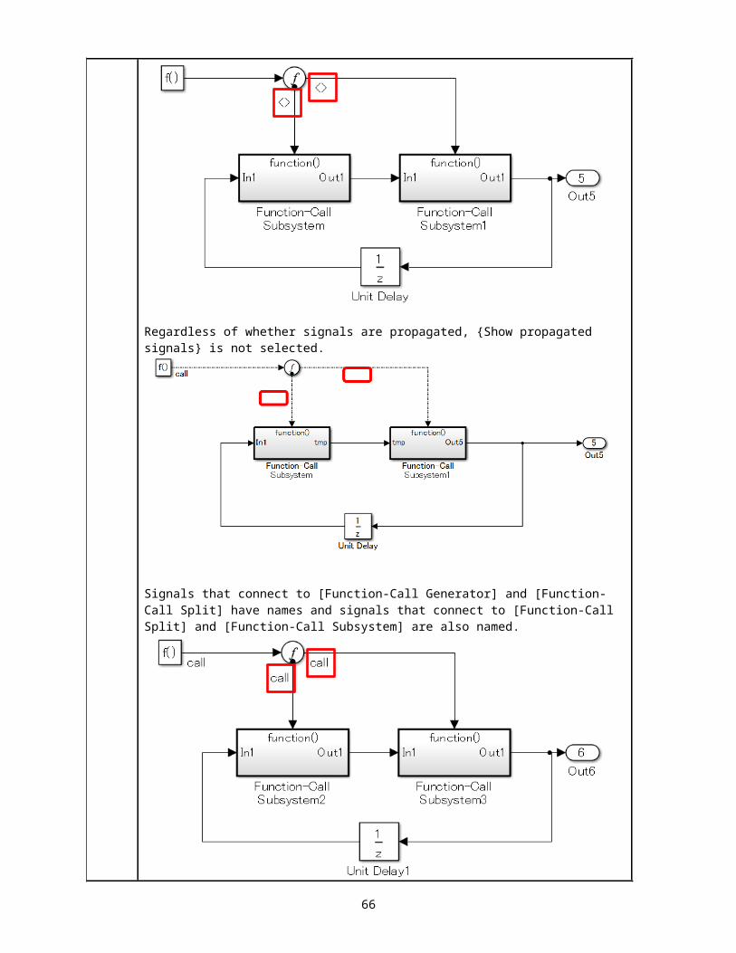
Regardless of whether signals are propagated, {Show propagated signals} is not selected.
Signals that connect to [Function-Call Generator] and [Function-Call Split] have names and signals that connect to [Function-Call Split] and [Function-Call Subsystem] are also named.
Rationale
58
Sub ID
Description
ab Prevents signal line connection mistakes. Prevents signal line name mistakes.
db_0097: Position of labels for signals and bussesRule ID: Title db_0097: Position of labels for signals and bussesSub ID Recommendations
NA-MAAB: a, b, cJMAAB: a, b, c
MATLAB® Version AllRuleSub ID Description Custom Parameter
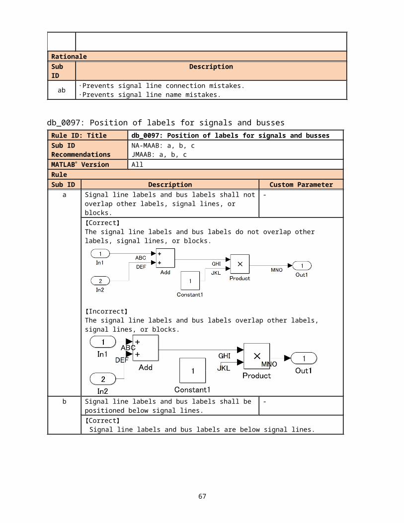
a Signal line labels and bus labels shall not overlap other labels, signal lines, or blocks.
-
【Correct】The signal line labels and bus labels do not overlap other labels, signal lines, or blocks.
【Incorrect】The signal line labels and bus labels overlap other labels, signal lines, or blocks.
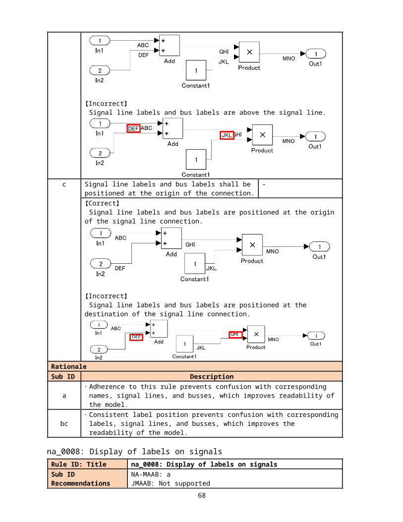
b Signal line labels and bus labels shall be positioned below signal lines.
-
【Correct】Signal line labels and bus labels are below signal lines.
【Incorrect】Signal line labels and bus labels are above the signal line.
59
c Signal line labels and bus labels shall be positioned at the origin of the connection.
-
【Correct】Signal line labels and bus labels are positioned at the origin of the signal line
connection.
【Incorrect】Signal line labels and bus labels are positioned at the destination of the signal line
connection.
RationaleSub ID Description
a Adherence to this rule prevents confusion with corresponding names, signal lines, and busses, which improves readability of the model.
bc Consistent label position prevents confusion with corresponding labels, signal lines, and busses, which improves the readability of the model.
na_0008: Display of labels on signalsRule ID: Title na_0008: Display of labels on signalsSub ID Recommendations
NA-MAAB: aJMAAB: Not supported
MATLAB® Version AllRuleSub ID Description Custom Parameter
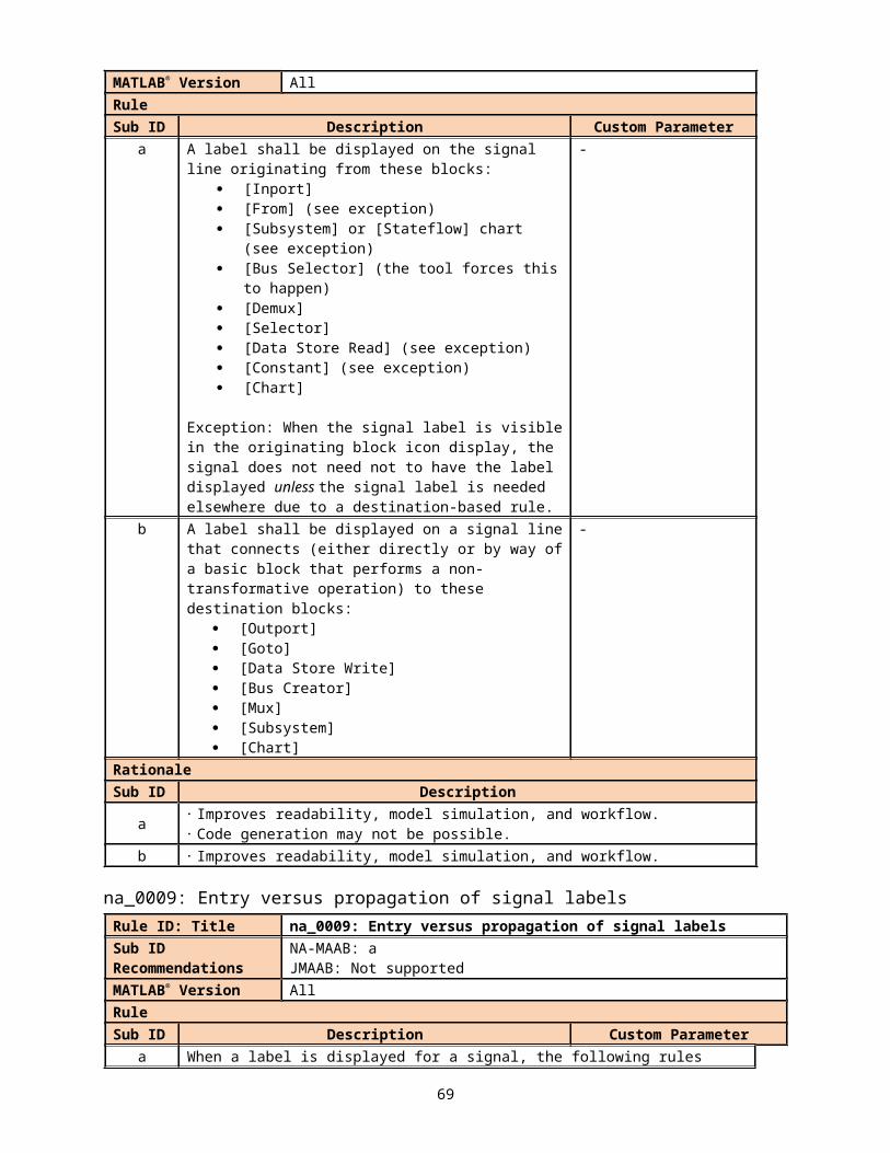
a A label shall be displayed on the signal line originating from these blocks:
[Inport] [From] (see exception) [Subsystem] or [Stateflow] chart (see exception) [Bus Selector] (the tool forces this to happen) [Demux] [Selector] [Data Store Read] (see exception) [Constant] (see exception) [Chart]
Exception: When the signal label is visible in the originating block icon display, the signal does not need not to have the label displayed unless the signal label is needed elsewhere due to a destination-based rule.
-
b A label shall be displayed on a signal line that connects (either directly or by way of a basic block that performs a non-transformative operation) to these destination blocks:
[Outport] [Goto]
-
60
[Data Store Write] [Bus Creator] [Mux] [Subsystem] [Chart]
RationaleSub ID Description
a Improves readability, model simulation, and workflow. Code generation may not be possible.
b Improves readability, model simulation, and workflow.
na_0009: Entry versus propagation of signal labelsRule ID: Title na_0009: Entry versus propagation of signal labelsSub ID Recommendations
NA-MAAB: aJMAAB: Not supported
MATLAB® Version AllRuleSub ID Description Custom Parameter
a
When a label is displayed for a signal, the following rules define whether that label is created there (entered directly on the signal) or propagated from its true source (inherited from elsewhere in the model by using the ‘<’ character).
Signal labels shall be entered for signals that originate from: [Inport] at the root (top) level of a model Basic blocks that perform a transformative operation (For the purpose of
interpreting this rule only, the [Bus Creator], [Mux], and [Selector] are included among the blocks that perform transformative operations.)
Signal labels shall be propagated for signals that originate from: [Inport] in a nested subsystem
Exception: When the nested subsystem is a library subsystem, a label can be entered on the signal coming from [Inport] to accommodate reuse of the library block.
Basic blocks that perform a non-transformative operation [Subsystem] or Stateflow [Chart]
Exception: When the connection originates from the output of a library subsystem block, a new label can be entered on the signal to accommodate readability.
The result of executing a MATLAB command is reflected in the code, which makes consistency between the model and code difficult to maintain.
db_0110: Block parametersRule ID: Title db_0110: Block parametersSub ID Recommendations
NA-MAAB: No recommendations JMAAB: a
MATLAB® Version AllRuleSub ID Description Custom Parameter
a Block parameters shall not be used to describe: Operation expressions Data type conversion Selection of rows or columns MATLAB commands
-
RationaleSub ID Description
a Operation expressions, data type conversion, or row or column selection become a
61
magic number in generated code, which makes consistency between the model and code difficult to maintain. Adjusting parameters also becomes difficult.
Describing the calculation formula within the block decreases readability. The result of executing a MATLAB command is reflected in the code, which makes
consistency between the model and code difficult to maintain.
db_0112: Usage of indexRule ID: Title db_0112: Usage of indexSub ID Recommendations
NA-MAAB: a1/a2JMAAB: a1/a2
MATLAB® Version AllRuleSub ID Description Custom Parameter
a1 A vector signal shall use a 1-based index mode. -【Correct】
A uniform 0-based index mode is used.
【Incorrect】A uniform index mode is not used.
62
a2 A vector signal shall use a 1-based index mode. -【Correct】
A uniform 1-based index mode is used.
63
【Incorrect】A uniform index mode is not used. (Same as db_0112, Sub ID_a1).
64
RationaleSub ID Description
a1a2 Logic is easier to understand when using a uniform index mode.
jc_0645: Parameter definition for calibrationRule ID: Title jc_0645: Parameter definition for calibrationSub ID Recommendations
NA-MAAB: No recommendationsJMAAB: a
MATLAB® Version AllRuleSub ID Description Custom Parameter
a Block parameters that are targets of calibration shall be defined as named constants
Examples of parameters that are outside of the calibration target include: Initial value parameter 0 Increment, decrement 1
-
【Correct】
65
【Incorrect】
RationaleSub ID Description
a A literal constant in the model will propagate as a literal constant in the generated code, making calibration impossible.
jc_0641: Sample time settingRule ID: Title jc_0641: Sample time settingSub ID Recommendations
NA-MAAB: No recommendationsJMAAB: a
MATLAB® Version AllRuleSub ID Description Custom Parameter
a Block parameter {Sample time} shall be set to “-1” (inherited).
Exceptions include: [Inport] [Outport] Atomic subsystem Blocks with state variables, such as [Unit Delay] and
[Memory] Signal conversion blocks, such as [Data Type
Conversion] and [Rate Transition] Blocks that do not have external inputs, such as
[Constant] [Chart]
-
RationaleSub ID Description
a
Discrepancies can occur in the processing of the model because of different simulation times.
Maintainability of the model deteriorates when a specific sample time is set for each block individually.
jc_0643: Fixed-point settingRule ID: Title jc_0643: Fixed-point settingSub ID Recommendations
NA-MAAB: No recommendationsJMAAB: a
MATLAB® Version AllRuleSub ID Description Custom Parameter
a When block parameters {Data type} is a fixed-point (fixdt) setting and {Scaling} is “Slope and bias”, parameter {Bias} shall be set to “0”.
-
RationaleSub ID Description
66
a
When the bias in a model is not uniform: Behavior of the model is impossible to determine by its appearance. Unintended overflows and underflows occur. Results in wasteful operation and deterioration of code efficiency/computing load.
jc_0644: Type settingRule ID: Title jc_0644: Type settingSub ID Recommendations
NA-MAAB: No recommendationsJMAAB: a
MATLAB® Version AllRuleSub ID Description Custom Parameter
a When the data type is set by a data object, a block or Stateflow data dictionary shall not be used to set the data type.
Exceptions (see rationale for more information): Inside a reusable function [Data Type Conversion] Data types set by using “fixdt” Boolean type, double type
-
【Correct】0611, not by the block.
RationaleSub ID Description
a When the data type is set in a block and it differs from the type setting in the data object, it can be difficult to determine which setting is correct. This can impair readability.
When the type is set in the block, —maintainability is affected when the signal line type changes.
Exceptions: Inside a reusable function
When all block structures are identical, differences between input/output data type
67
can result in different C source code that is not reusable. For reusable functions, data types of input/output blocks should be specified at the subsystem level.
[Data Type Conversion]This block is used to explicitly set the data type.
Data types set by using “fixdt”When fixed-point is selected, data type must be set individually because each block can have different data points. In this scenario, it is impossible to use only the data object to set the data type.
Boolean type, double typeSome block types must be set to Boolean.Double type is generally used in plant models and for Rapid Control Prototyping
(RCP), therefore it is not within scope of this rule.Embedded software uses double type in specific situations. Use caution when
configuring the settings on these blocks to minimize the use of double type.
3.4. Conditional subsystem relations
db_0146: Block layout in conditional subsystemsRule ID: Title db_0146: Block layout in conditional subsystemsSub ID Recommendations
NA-MAAB: a, bJMAAB: a, b
MATLAB® Version AllRuleSub ID Description Custom Parameter
a Conditional input blocks shall be positioned at the top of the subsystem.
-
【Correct】
【Incorrect】
68
b The position of these blocks shall be defined by the project: [For Each] [For Iterator] [While Iterator]
Location layout
RationaleSub ID Description
ab Unifying the internal and external layout of the conditional subsystem improves readability of the model.
jc_0640: Initial value settings for Outport blocks in conditional subsystemsRule ID: Title jc_0640: Initial value settings for Outport blocks in conditional
subsystemsSub ID Recommendations
NA-MAAB: No recommendationsJMAAB: a
MATLAB® Version AllRuleSub ID Description Custom Parameter
a When both conditions are met for a conditional subsystem:- Includes a block with initial conditions (i.e.
[Constant] and [Delay])- Connects to [Outport]
The initial condition shall be defined on [Outport].
However, when the output signal from a conditional subsystem is connected to [Merge], the initial condition shall be defined on [Merge].
-
【Correct】The initial condition is defined.
69
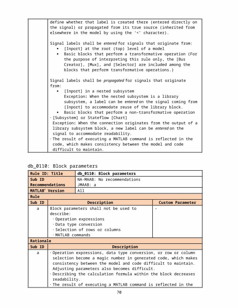
【Incorrect】The initial condition is undefined.
70
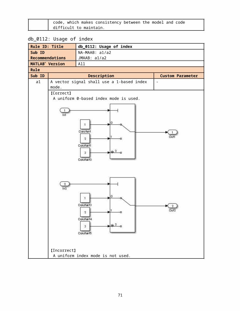
RationaleSub ID Description
a The model may not behave as intended when the initial condition is unclear.
jc_0659: Usage restrictions of signal lines input to Merge blocksRule ID: Title jc_0659: Usage restrictions of signal lines input to Merge blocksSub ID Recommendations
NA-MAAB: No recommendationsJMAAB: a
MATLAB® Version AllRuleSub ID Description Custom Parameter
a Only conditional subsystem output signals shall input to [Merge].
-
【Correct】Conditional subsystem output signal is input to [Merge].
71
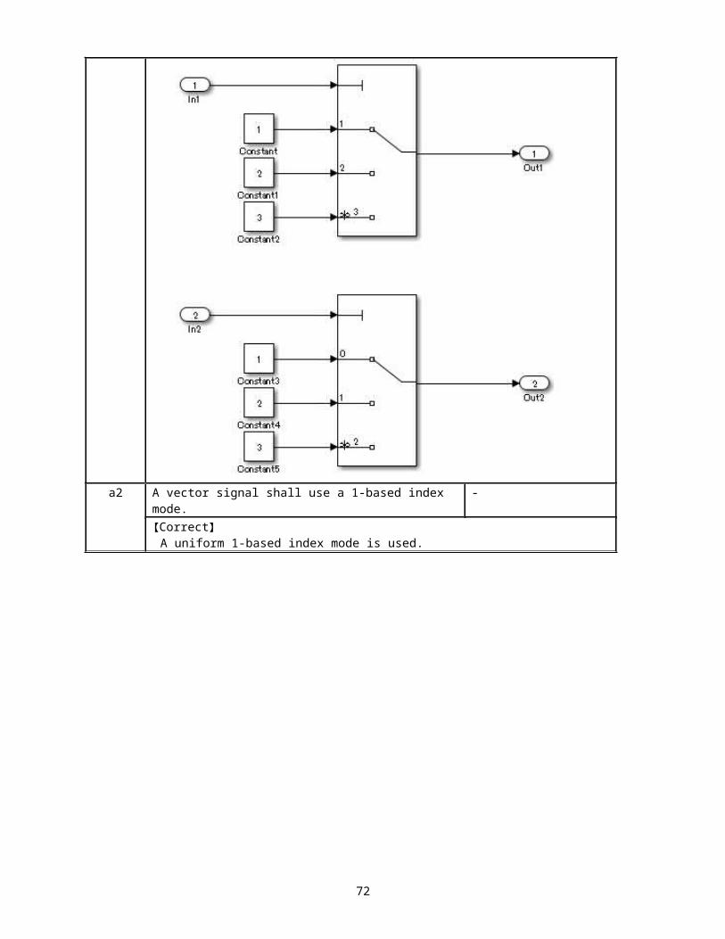
【Incorrect】0
RationaleSub ID Description
a Prevents the simulation from proceeding as intended.
na_0003: Usage of If blocksRule ID: Title na_0003: Usage of If blocksSub ID Recommendations
NA-MAAB: No recommendationsJMAAB: a
MATLAB® Version AllRuleSub ID Description Custom Parameter
a For [If], the {If expression} and {Elseif expression} shall be used only to define input signals.
-
【Correct】The {If expression} only defines the input variables.
72
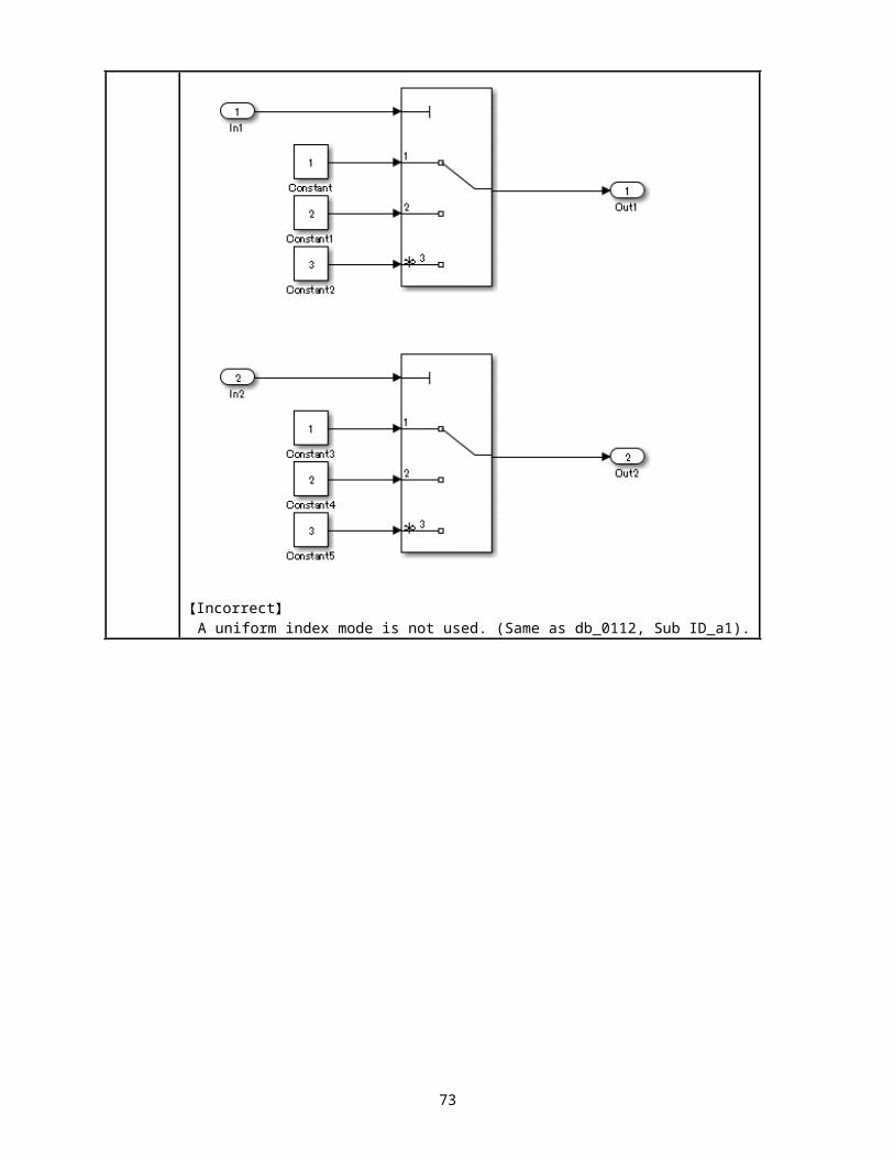
【Incorrect】The {If expression} defines a comparison operation.
RationaleSub ID Description
a
Visual comprehension of control conditions is easier when logical operations are described outside of [If].
Describing logical operations outside of [If] allows verification to focus on the logical operation.
jc_0656: Usage of Conditional Control blocksRule ID: Title jc_0656: Usage of Conditional Control blocksSub ID Recommendations
NA-MAAB: No recommendationsJMAAB: a
MATLAB® Version AllRuleSub ID Description Custom Parameter
a These block parameters shall be used to make all actions in the conditions explicit: For [If], select {Show else condition} For [Switch Case], select {Show default case}
-
【Correct】Default behavior
73
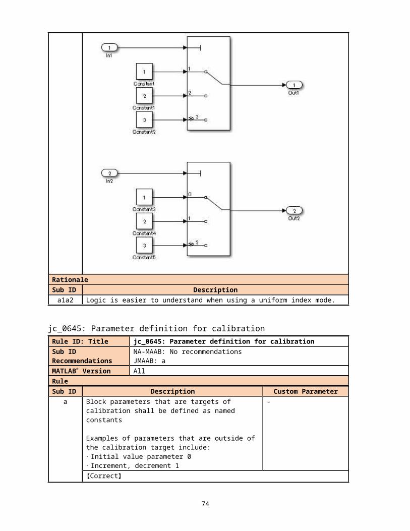
【Incorrect】No default behavior
RationaleSub ID Description
aDetermining whether there is pointless processing or if something is missing from the design (such as a missing description) is easier when the processing of exceptions (else, default) is explicitly set in the model .
jc_0657: Retention of output value based on conditional control flow blocks and Merge blocks
Rule ID: Title jc_0657: Retention of output value based on Conditional Control Flow blocks and Merge blocks
Sub ID Recommendations
NA-MAAB: a2JMAAB: a1/a2
MATLAB® Version AllRuleSub ID Description Custom Parameter
a1 Unused action ports shall connect to [Terminator] when these conditions are met:
- Past value is retained- [Merge] and a conditional flow block, such as [If]
or [Switch Case], are used to switch functions.
-
【Correct】
74
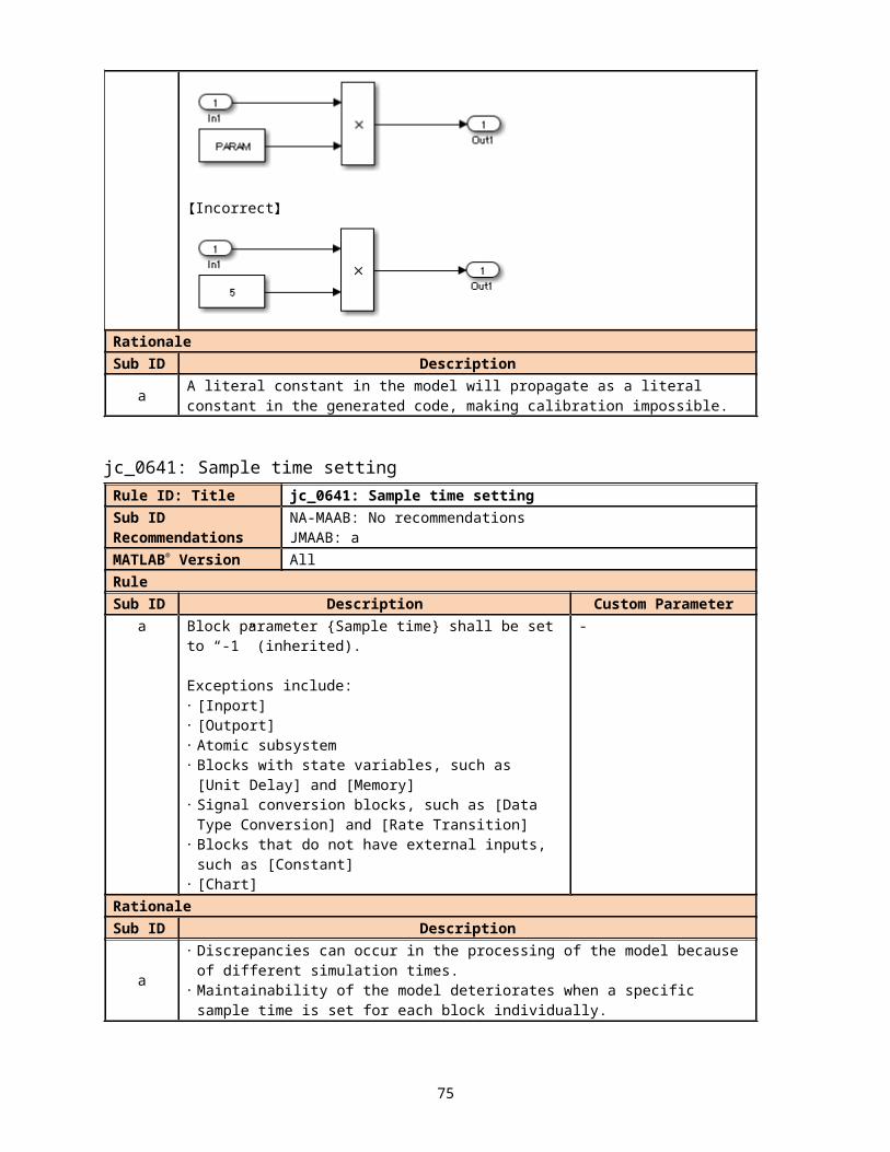
[If] example
[Switch Case] example
【Incorrect】[If] example
75
[Switch Case] example
a2 A feedback loop using [Delay] shall be implemented when these conditions are met:
- Past value is retained- [Merge] and a conditional flow block, such as [If]
or [Switch Case], are used to switch functions.
-
【Correct】[if] example
76
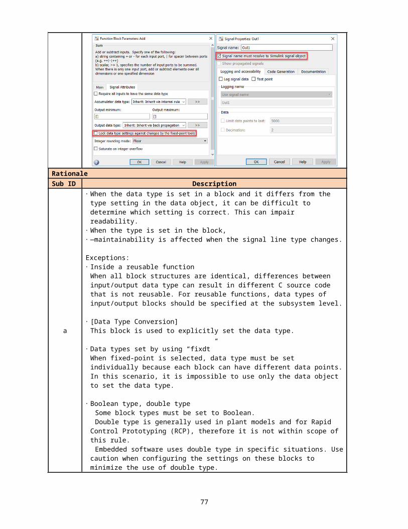
[Switch Case] example
【Incorrect】[If] example
77
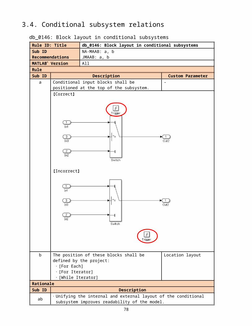
[Switch Case] example
RationaleSub ID Description
a1 Improves code efficiency. Connections to [Terminator] can be used when past values are held other than by the
default (else).a2 Retaining past values is explicit.
3.5. Operation blocks
na_0002: Appropriate usage of basic logical and numerical operationsRule ID: Title na_0002: Appropriate usage of basic logical and numerical
operationsSub ID Recommendations
NA-MAAB: a, bJMAAB: a, b
MATLAB® Version AllRuleSub ID Description Custom Parameter
a Logical signals shall not connect to blocks that operate on Blocks receiving
78
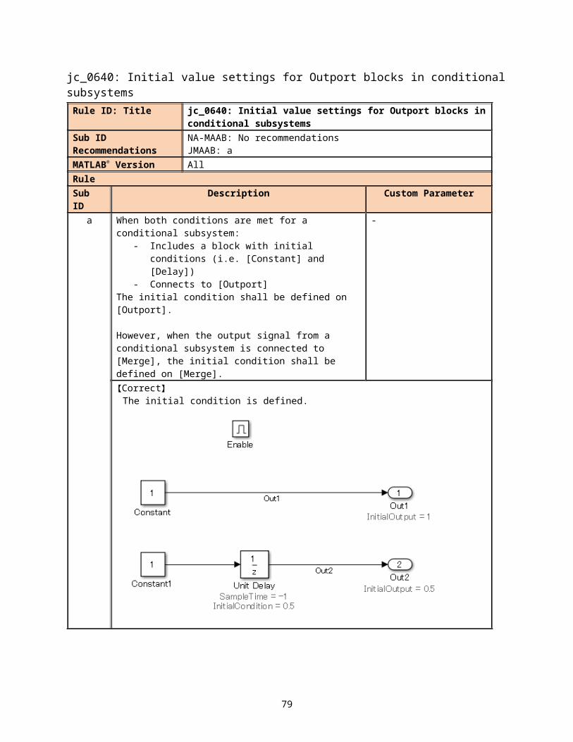
numerical signals. numerical signals【Correct】
Numerical values are compared to determine if they are equal.
【Incorrect】A logical output is connected directly to the input of blocks that process numerical
inputs.
A logical signal is compared with a numerical value.
b Numerical signals shall not connect to blocks that operate on logical signals.
Blocks receiving logical signals
【Correct】
79
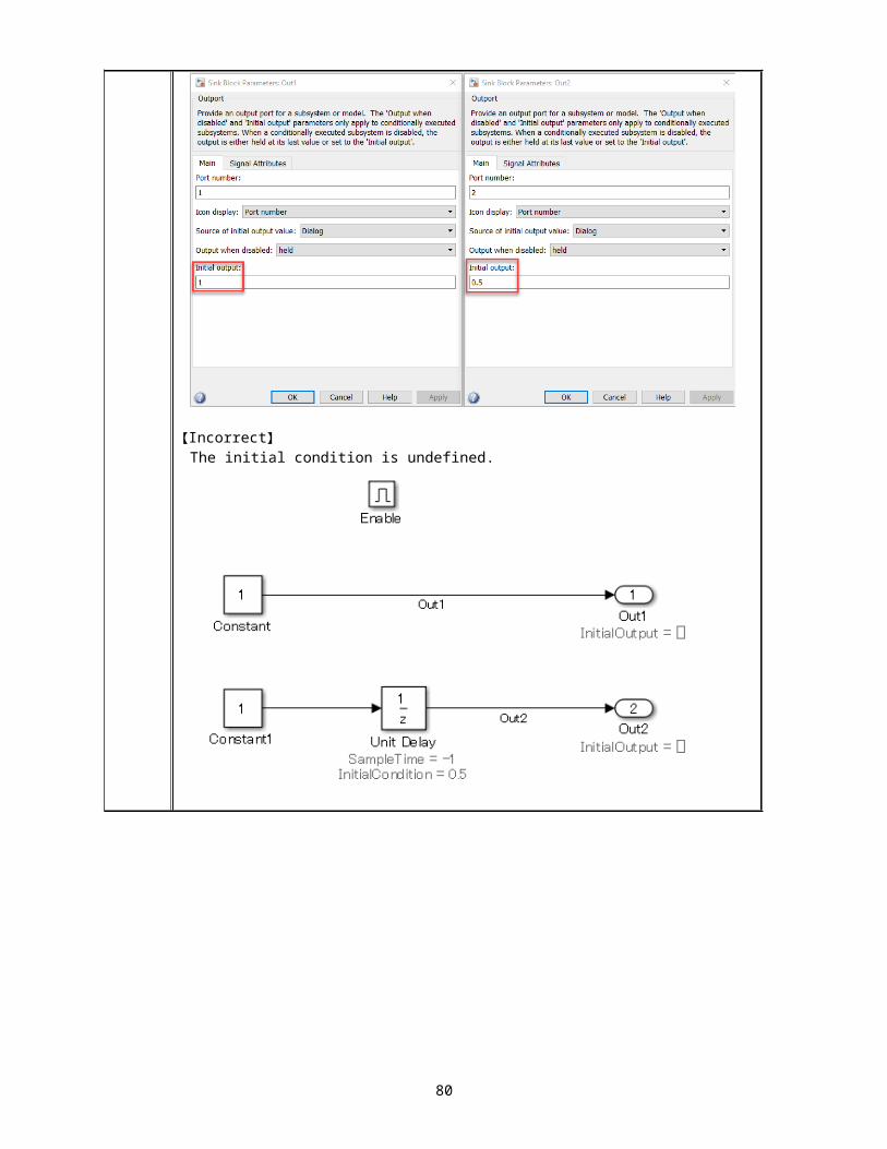
Logical signal is inverted by using a logical operation.
Logical signal is evaluated by using a logical operation.
【Incorrect】 A block that is used to perform logical operations is being used to perform numerical
operations. A numerical output is connected to the input of blocks that process logical inputs.
A block that is used to perform numerical operations is being used to perform logical operations.
Inputs other than logical values can be provided to the block. However, [Enable Port] can receive only logical signals that have On/Off.
[Product] performs logical operations when it connects the numerical operations
80
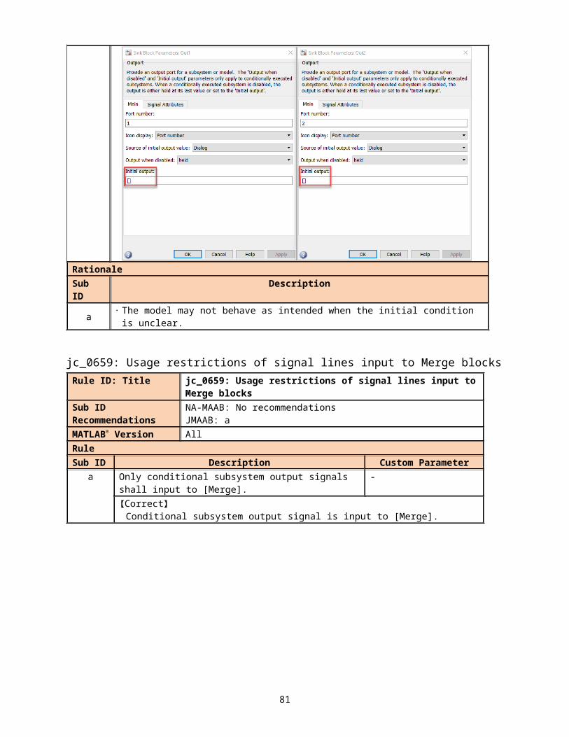
result to a block that receives the logical value [Enable Port].
RationaleSub ID Description
ab When numerical and logical values are treated the same, the original intention
becomes unclear and the next operation in the model can be incorrectly interpreted, further compounding the error.
jc_0121: Usage of add and subtraction blocksRule ID: Title jc_0121: Usage of add and subtraction blocksSub ID Recommendations
NA-MAAB: aJMAAB: a, b, c
MATLAB® Version AllRuleSub ID Description Custom Parameter
a The {icon shape} of the add and subtraction [Sum] block shall be “rectangular”.When used in a feedback loop, the {icon shape} can be “round”.
-
【Correct】The {icon shape} for the add and subtraction [Sum] block is “rectangular”.
1In1 1
Out12In2
Sum
In1Out1
In2
The second input to the add and subtraction [Sum] block is a feedback loop, so the {icon shape} is “round”.
【Incorrect】This is not a feedback loop, but the {icon shape} of the add and subtraction [Sum]
block is “round”.
81
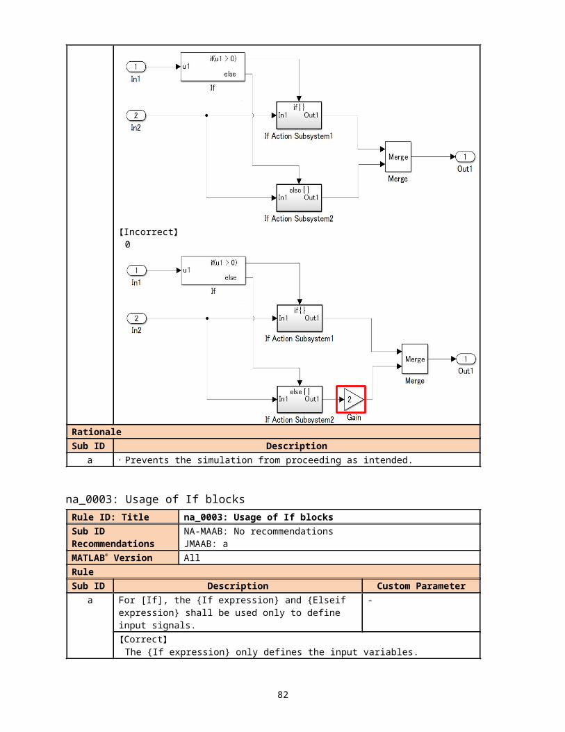
b The “+” mark shall be used for the first input to the add and subtraction [Sum] block.For a feedback loop, the first input can be set by using the “-” mark.
-
【Correct】The “+” mark is used for the first input to the add and subtraction [Sum] block.
1In1 1
Out12In2
Sum
In1
In2Out1
The second input to the add and subtraction [Sum] block is a feedback loop, so the “-” mark is used.
1In1
1Out1
K
z1
Out1
Out1_old
In1【Incorrect】
The sign for the first input to the add and subtraction [Sum] block is the “-” mark.
c The add and subtraction [Sum] block shall not have more than two inputs.
-
【Correct】The add and subtraction [Sum] block has no more than two inputs.
82
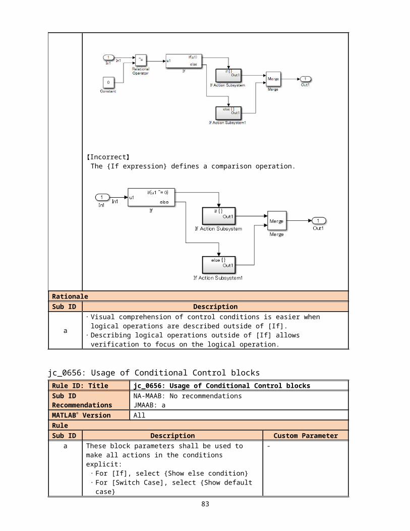
1In1 1
Out12In2
Sum
In1
In2Out1
【Incorrect】The add and subtraction [Sum] block has three inputs.
RationaleSub ID Description
a Adherence to the guideline improves readability of the model.
b Readability of the control specification improves when the sign for the first input is consistent.
c The order of operations is clearly defined.
jc_0610: Operator order for multiplication and division blocksRule ID: Title jc_0610: Operator order for multiplication and division blocksSub ID Recommendations
NA-MAAB: No recommendationsJMAAB: a, b, c
MATLAB® Version AllRuleSub ID Description Custom Parameter
a The “*” mark shall be used for the first input to a multiplication and division [Product] block.
-
【Correct 】The “*” mark is used for the first input to the multiplication and division [Product]
block.
83
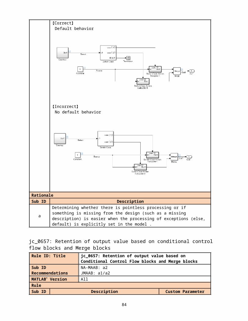
【Incorrect】 The “/” mark is used for the first input to the multiplication and division [Product]
block.
b The multiplication and division [Product] block shall have
no more than two inputs.-
【Correct 】The block has two inputs.
【Incorrect】 The block has three inputs.
RationaleSub ID Description
a
When checking the block, the input order of the expression and block is reversed, which impairs readability.
For floating point numbers, the code is generated according to the operation order in the block ((1÷1st input)) × 2nd input). However, if division is performed later, the number of operations can be reduced.
b The order of operations is clearly defined.
jc_0611: Input sign for multiplication and division blocksRule ID: Title jc_0611: Input sign for multiplication and division blocksSub ID Recommendations
NA-MAAB: aJMAAB: a
MATLAB® Version AllRuleSub ID Description Custom Parameter
84
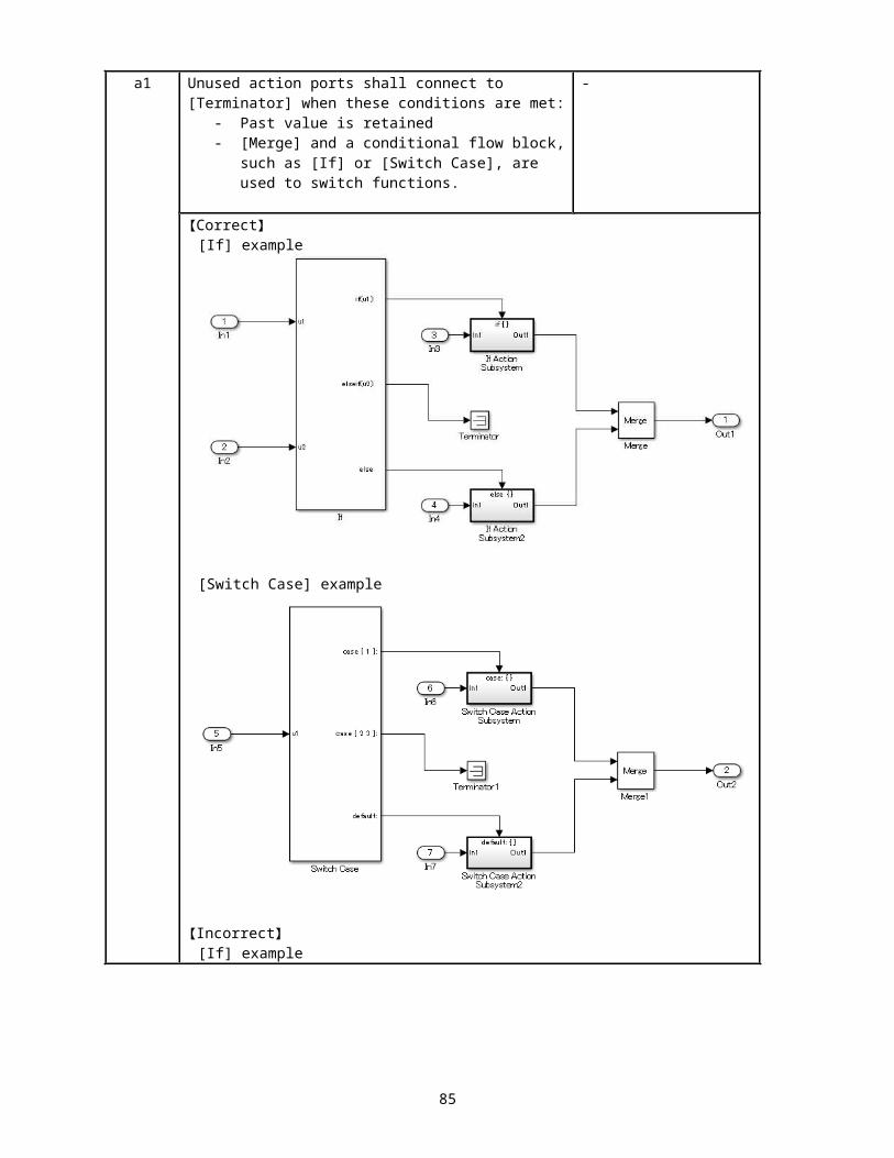
a When using fixed-point values as the input to the multiplication and division [Product] block, the sign of the data type shall be the same for all input signals.
-
RationaleSub ID Description
a A utility function is created for each least significant bit (LSB) when fixed-point code is generated. Unification of data type signs can reduce the number of utility functions.
jc_0794: Division in SimulinkRule ID: Title jc_0794: Division in SimulinkSub ID Recommendations
NA-MAAB: aJMAAB: a
MATLAB® Version AllRuleSub ID Description Custom Parameter
a When using division, implementation of the algorithm shall avoid division by zero.
-
RationaleSub ID Description
a Deviation from the rule can cause unintended operation and code generation results.
jc_0805: Numerical operation block inputsRule ID: Title jc_0805: Numerical operation block inputsSub ID Recommendations
NA-MAAB: a1/a2, b, c1/c2, d, e, f1/f2, g, h, i, jJMAAB: a1/a2, b, c1/c2, d, e, f1/f2, g, h, i, j
MATLAB® Version AllRuleSub ID Description Custom Parameter
a1 When using [Abs] with signed integer types, the input shall not be the most negative value.
-
【Correct】
【Incorrect】
a2 [Abs] block parameter {Saturation on Integer Overflow} shall be selected.
-
【Correct】
85
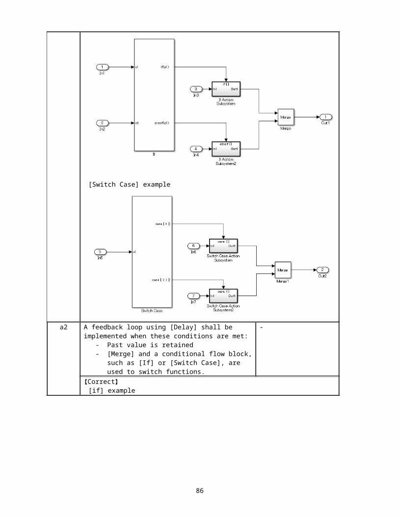
【Incorrect】
b Input to [Abs] shall not be unsigned integer types or fixed-point types.
-
【Correct】
【Incorrect】
c1 Input to [Sqrt] shall not be a negative value. -【Correct】
Negative number is saturated with 0.
Simulation result
86
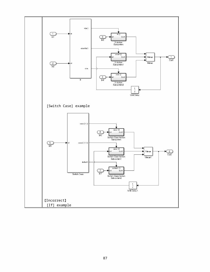
【Incorrect】
c2 [Sqrt] block parameter {Output Signal Type} shall be set to “complex”.
-
【Correct】
【Incorrect】
d Input to [Reciprocal Sqrt] shall not be less than zero. -【Correct】
Less than eps saturated with eps
Simulation result: Plot as Y=log10(Z)
87
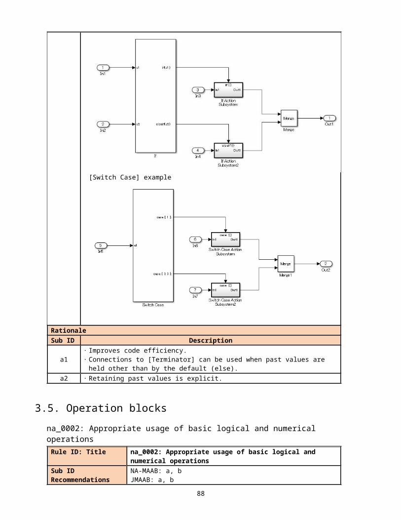
【Incorrect】
e When using [Math Function] and block parameter {Function} is set to “log” or “log10”, the input to the block shall not be zero.
-
【Correct】Replace within ±eps with ±eps
Simulation result: Plot as Y = |Z|
【Incorrect】
f1 When using [Math Function] and block parameter -
88
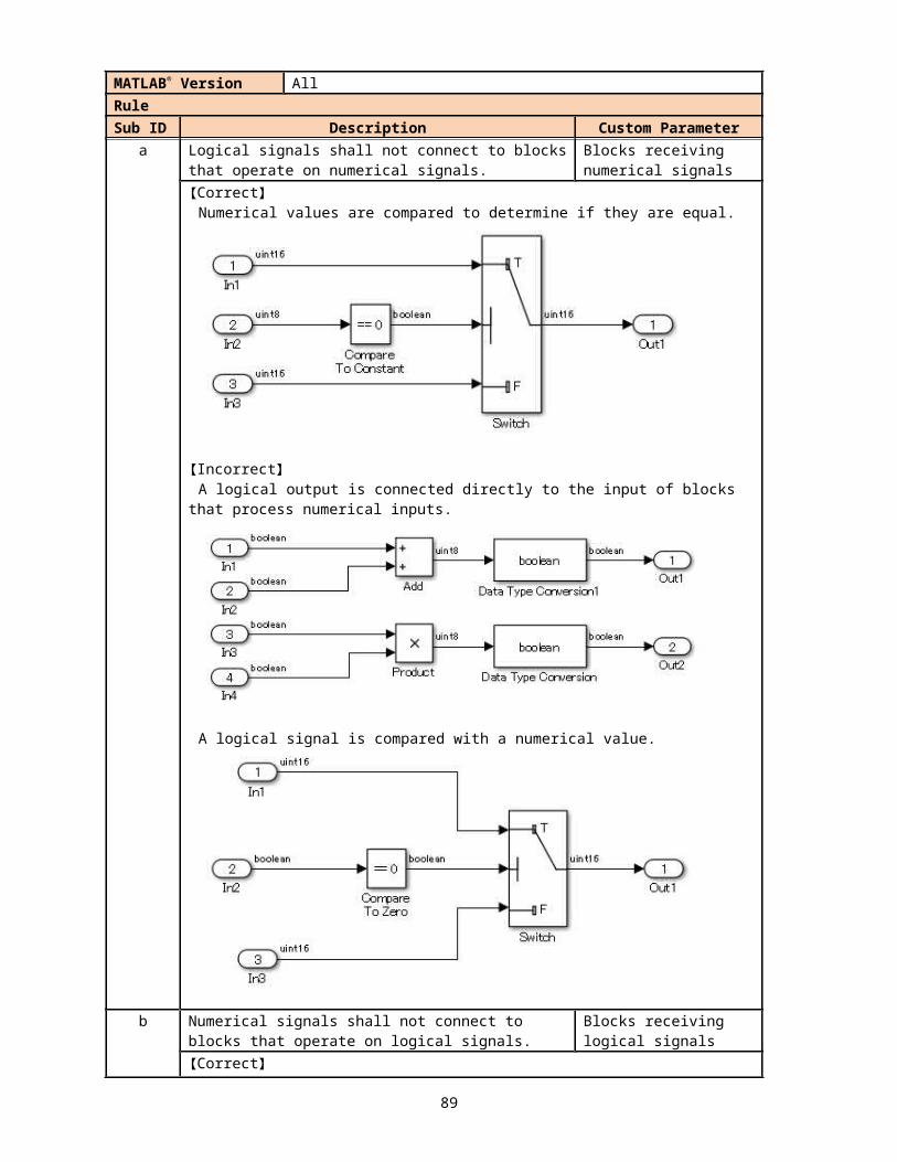
{Function} is set to “log” or “log10”, the input to the block shall not be a negative number.【Correct】
When the input is less than eps, the value is saturated to eps. Less than eps saturated with eps.
Simulation result
【Incorrect】
f2 When using [Math Function] and block parameter {Function} is set to “log” or “log10”, block parameter {Output Signal Type} shall be set to “complex”.
-
【Correct】
【Incorrect】
g When using [Math Function] and block parameter {Function} is set -
89
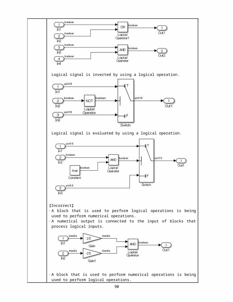
to “mod” or “rem”, the second argument input shall not be zero.【Correct】
【Incorrect】
h When using [Math Function] and block parameter {Function} is set to “reciprocal”, the input to the block shall not be zero.
-
【Correct】Replace within ±eps with ±eps
Simulation result: Simulation results is not inf, but since it is close to zero, the change in the output value is significant.
90
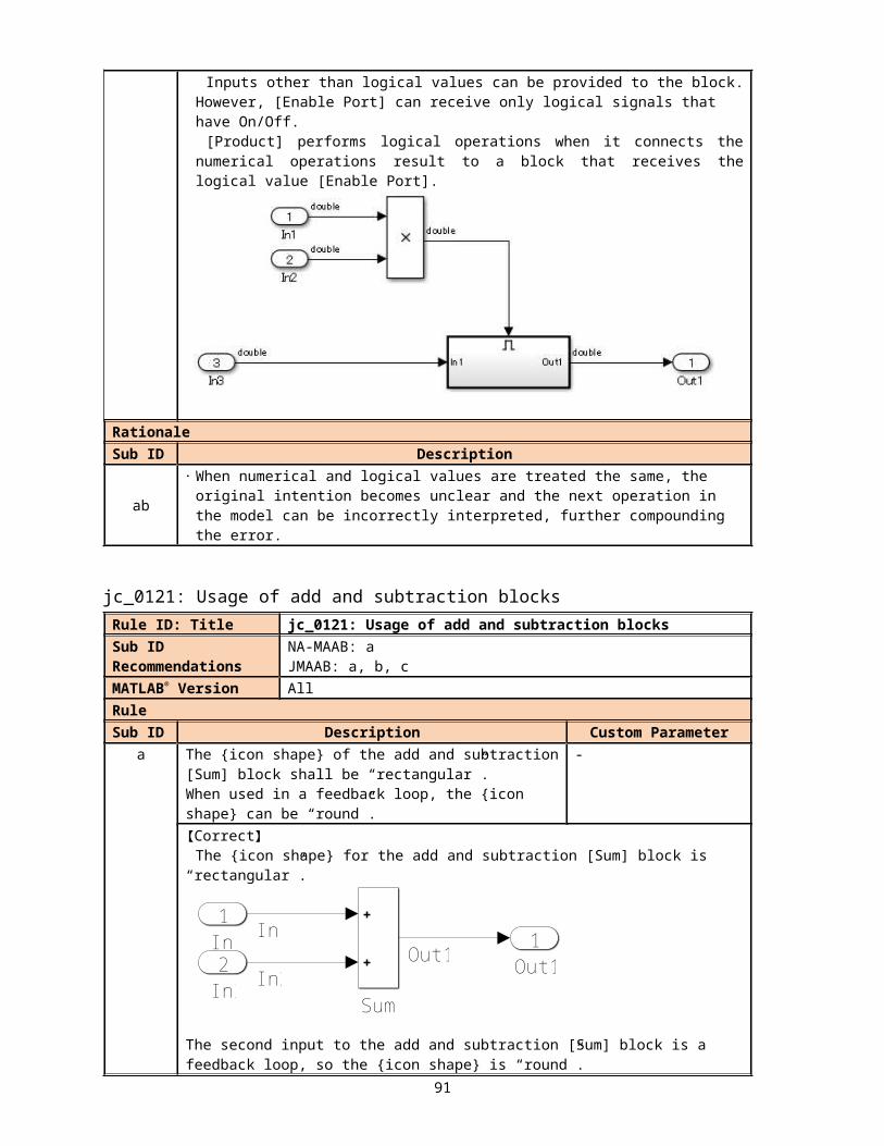
【Incorrect】
i When [Product] block parameter {Multiplication} is set to “Element-wise(.*)”, the divisor input shall not be zero.Note: To specify a divisor input, set [Product] block parameter {Number of inputs} to “*/”.)
-
【Correct】
【Incorrect】
j When [Product] block parameter {Multiplication} is set to “Matrix(*)”, the divisor input shall not be set to a singular matrix.Note: To specify a divisor input, set [Product] block parameter {Number of inputs} to “*/”.)
-
【Correct】
【Incorrect】
RationaleSub ID Descriptiona1c1def The result of entering an invalid value is implementation dependent. Deviation from the
91
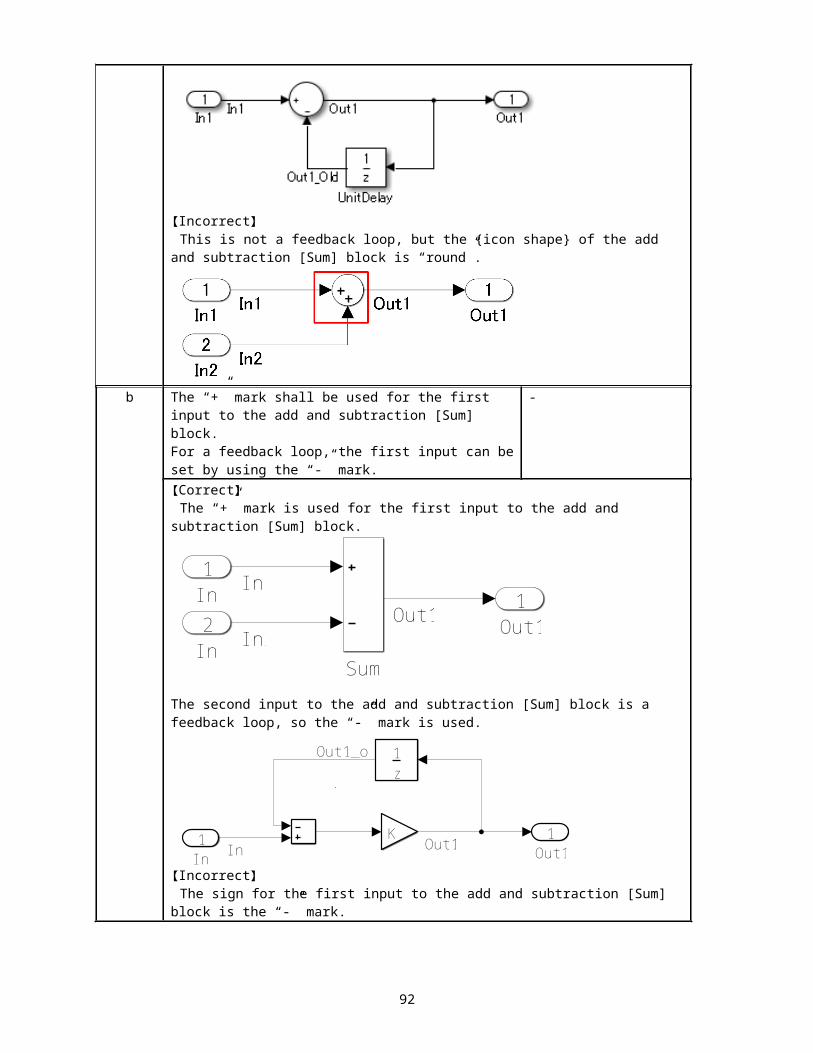
1ghij rules can result in unintended behavior.a2 Correct settings prevent unintended behavior that can result from using invalid values.
b The block can become optimized out of the generated code, resulting in a block that you cannot trace to the generated code.
c2f2 Correct settings prevent unintended behavior that can result from using negative values.
jc_0622: Usage of Fcn blocksRule ID: Title jc_0622: Usage of Fcn blocksSub ID Recommendations
NA-MAAB: No recommendationsJMAAB: a
MATLAB® Version AllRuleSub ID Description Custom Parameter
a When [Fcn] has operators with different priorities, parentheses shall be used to specify the priority order.
-
RationaleSub ID Description
aWhen operators have different priorities and the computation order is not clearly specified by using parentheses, readability is impaired and can be misinterpreted. This can result in unintended behavior.
jc_0621: Usage of Logical Operator blocksRule ID: Title jc_0621: Usage of Logical Operator blocksSub ID Recommendations
NA-MAAB: aJMAAB: a
MATLAB® Version AllRuleSub ID Description Custom Parameter
a The {icon shape} for [Logical Operator] shall be set to “rectangular”.
-
【Correct】The icon shape for [Logical Operator] is set to “rectangular”.
【Incorrect】Some of the icon shapes for [Logical Operator] are not “rectangular”.
92
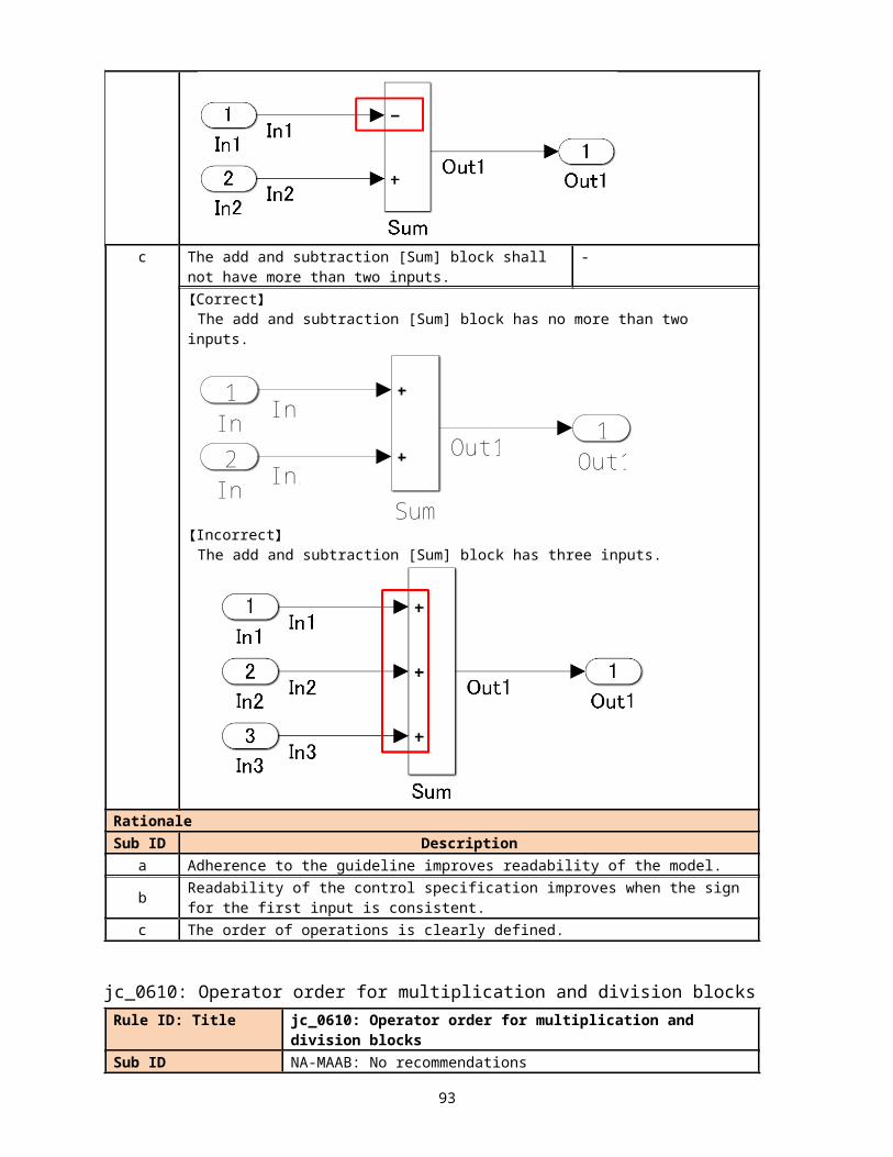
RationaleSub ID Description
aWhen describing the same function, using a consistent expression improves readability. Since “Characteristics” shapes are similar, the risk of misinterpretation is greater than with “rectangular” shapes.
jc_0131: Usage of Relational Operator blocksRule ID: Title jc_0131: Usage of Relational Operator blocksSub ID Recommendations
NA-MAAB: aJMAAB: a
MATLAB® Version AllRuleSub ID Description Custom Parameter
a When using [Relational Operator] for comparison of signals and constants, the second (bottom) input shall be used as the constant input.
-
【Correct】
【Incorrect】
RationaleSub ID Description
a Using constant values and the same comparison method reduces misinterpretation of the model.
93
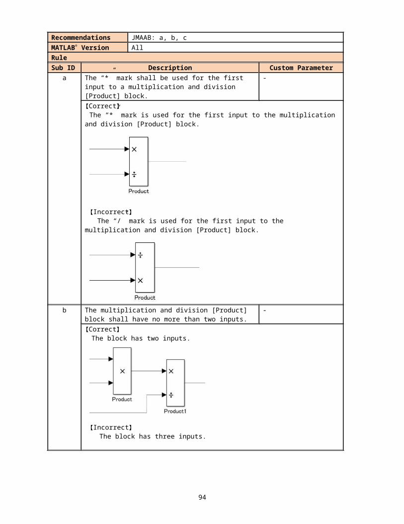
jc_0800: Comparing floating-point types in SimulinkRule ID: Title jc_0800: Comparing floating-point types in SimulinkSub ID Recommendations
NA-MAAB: aJMAAB: a
MATLAB® Version AllRuleSub ID Description Custom Parameter
a Equivalence comparison operators (==, ~=) shall not be used on floating-point data types.
-
【Correct】
【Incorrect】Uses floating-point type equivalence comparison operations (==, ~=).
RationaleSub ID Description
aDue to the characteristics of the floating-point, since the error is included in the value, the result of the equivalence comparison operation may be false when it was expected to be true.
jc_0626: Usage of Lookup Table blocksRule ID: Title jc_0626: Usage of Lookup Table blocksSub ID Recommendations
NA-MAAB: a, bJMAAB: a, b
MATLAB® Version AllRuleSub ID Description Custom Parameter
a [Lookup Table Dynamic] block parameter {Lookup Method} shall be set to “Interpolation – Use End Values”.
-
b These [n-D Lookup Table] block parameters shall be set:- Set {Interpolation Method} to “Linear point-slope”
or “Linear Lagrange”- Set {Extrapolation Method} to “Clip”
-
94
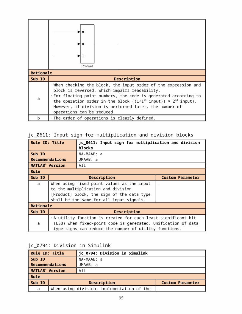
Select {Use last table value for inputs at or above last breakpoint}.
RationaleSub ID Description
abWhen an unexpected value is entered for [Lookup Table], the output is determined by using the extrapolation method and can become an impossible value or cause the [Lookup Table] output to overflow.
jc_0623: Usage of continuous-time Delay blocks and discrete-time Delay blocksRule ID: Title jc_0623: Usage of continuous-time Delay blocks and discrete-
time Delay blocksSub ID Recommendations NA-MAAB: a
JMAAB: aMATLAB® Version AllRuleSub ID Description Custom Parameter
a [Unit Delay] or [Delay] shall be used in a discrete model or subsystem. [Memory] shall be used in a continuous type model or subsystem.
-
【Correct】 [Unit Delay] is used in the discrete type model or subsystem.
【Incorrect】 [Memory] is used in the discrete type model or subsystem.
95
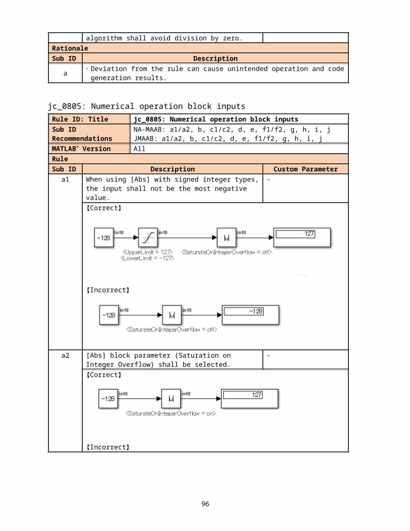
RationaleSub ID Description
a Adherence to the rule improves readability of the model.
jc_0624: Usage of Tapped Delay blocks/Delay blocksRule ID: Title jc_0624: Usage of Tapped Delay blocks/Delay blocksSub ID Recommendations
NA-MAAB: No recommendationsJMAAB: a, b
MATLAB® Version AllRuleSub ID Description Custom Parameter
a When holding previous past values, [Tapped Delay] shall be used to create a vector signal from all held values.
-
【Correct】[Tapped Delay] is used.
【Incorrect】[Tapped Delay] is not used.
96
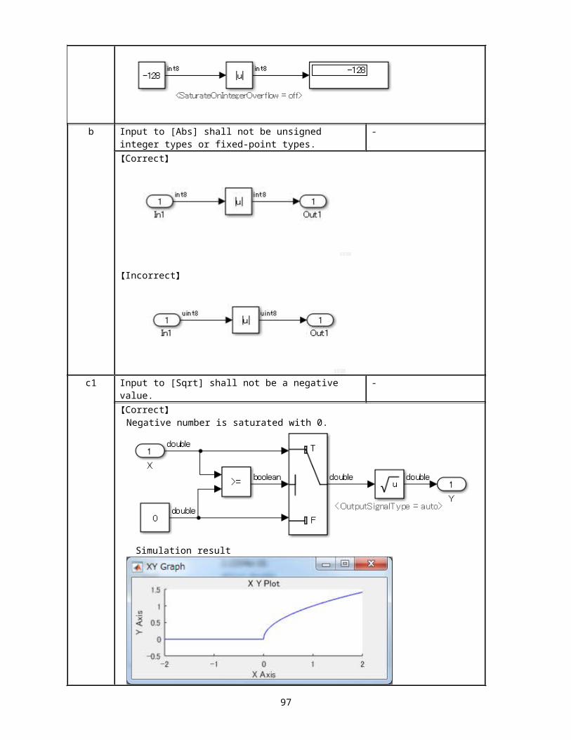
b When holding past values, [Delay] shall be used to obtain the oldest value only.
-
【Correct】[Delay] is used.
【Incorrect】[Delay] is not used.
RationaleSub ID Description
a [Tapped Delay] is set with arrays that hold past values, which improves code readability to assist code efficiency.
B Improves model readability and code efficiency.
jc_0627: Usage of Discrete-Time Integrator blocksRule ID: Title jc_0627: Discrete-Time Integrator blocksSub ID Recommendations
NA-MAAB: aJMAAB: a, b
MATLAB® Version AllRuleSub ID Description Custom Parameter
a [Discrete-Time Integrator] block parameters {Upper saturation limit} and {Lower saturation limit} shall be defined.
-
【Correct】Block parameters {Upper saturation limit} and {Lower saturation limit} are defined.
97
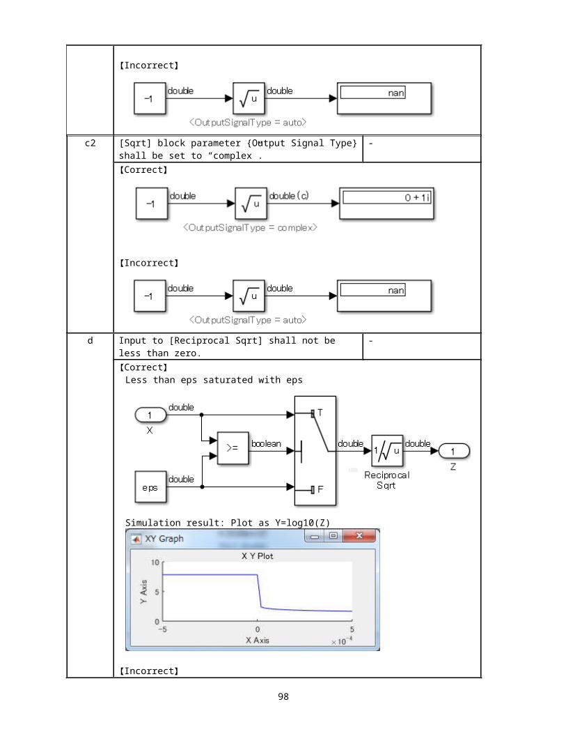
【Incorrect】Block parameters {Upper saturation limit} and {Lower saturation limit} are not defined.
Jc_0627b When [Discrete-Time Integrator] block parameters {Upper
saturation limit} and {Lower saturation limit} are defined as Simulink.Parameter, parameter {Data type} shall be set to “auto”.
-
【Correct】{Data type} is set to “auto”.
98
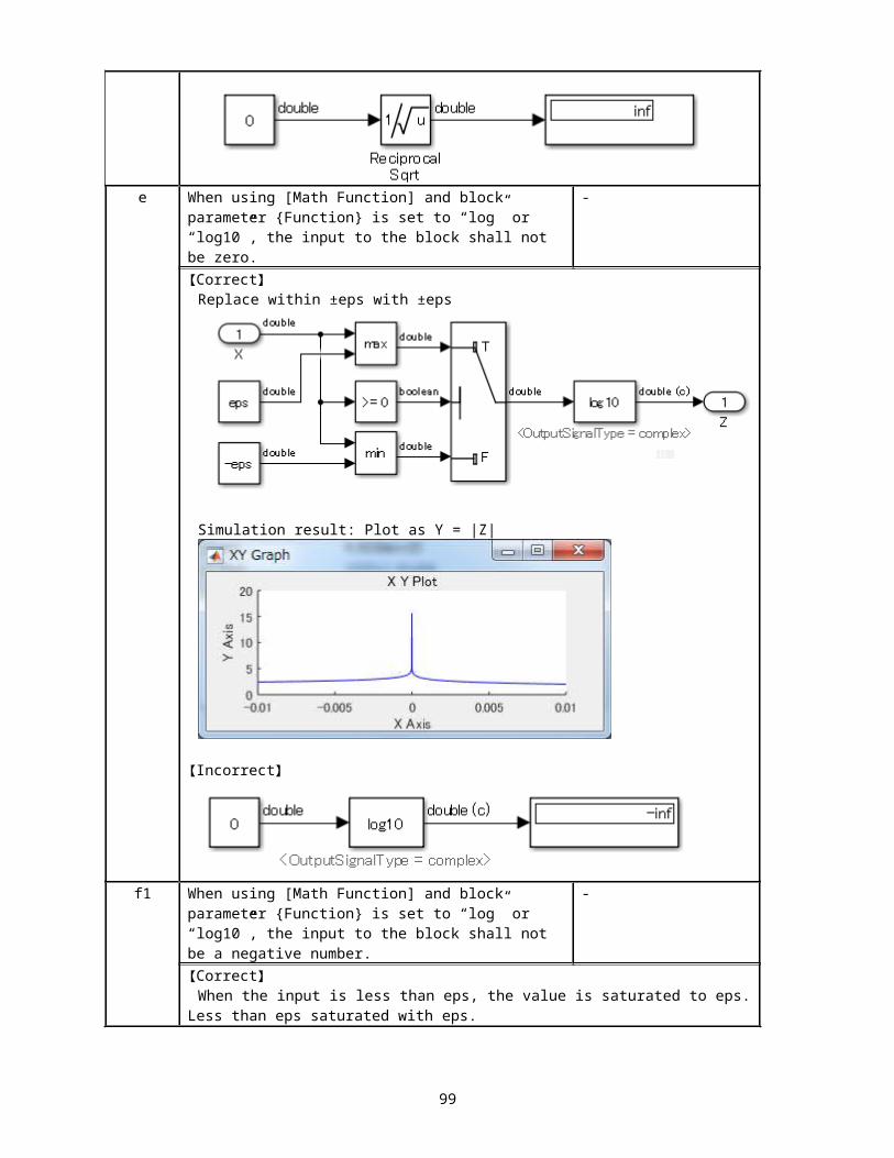
【Incorrect】{Data type} is not set to “auto”.
RationaleSub ID Description
a Avoids block output overflow and prevents other computation blocks that use the output of this block from producing unexpected results.
B Simulation errors occur when {Data type} is set to a value other than “auto”, “single”, or “double”.
99
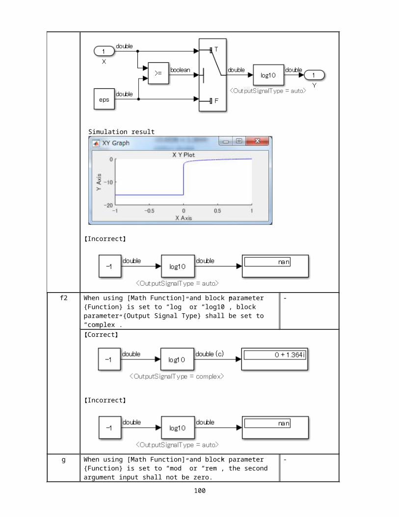
jc_0628: Usage of Saturation blocksRule ID: Title jc_0628: Usage of Saturation blocksSub ID Recommendations
NA-MAAB: aJMAAB: a
MATLAB® Version AllRuleSub ID Description Custom Parameter
a [Saturation] and [Saturation Dynamic] shall be used to limit physical quantity. Type conversion shall not be used. The upper and lower limits for the data type maximum and minimum values shall not be set.
-
【Correct】[Saturation Dynamic] is used to limit physical quantity. Type conversion is not being
used.
【Incorrect】[Saturation Dynamic] is not being used to limit physical quantity. Type conversion is
being used. The upper and lower limits for the data type maximum and minimum values are set.
RationaleSub ID Description
a Consistent use of [Saturation] improves maintainability of the model.
jc_0651: Implementing a type conversionRule ID: Title jc_0651: Implementing a type conversionSub ID Recommendations
NA-MAAB: No recommendationsJMAAB: a
MATLAB® Version All
100
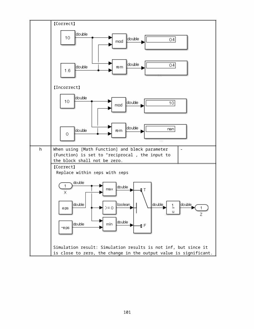
RuleSub ID Description Custom Parameter
a [Data Type Conversion] shall be used when changing the data type of the block output signal.
-
【Correct】[Data Type Conversion] is used to convert the data type of the [Divide] output signal.
【Incorrect】[Data Type Conversion] is not used to convert the data type of the [Divide] output
signal.
RationaleSub ID Description
a Dividing the math operations and type cast can help to clarify the order of execution and data type for each expression.
3.6. Other blocks
db_0042: Usage of Inport and Outport blocksRule ID: Title db_0042: Usage of Inport and Outport blocksSub ID Recommendations
NA-MAAB: a, bJMAAB: a, b, c
MATLAB® Version AllRuleSub ID Description Custom Parameter
a [Inport] shall be positioned on the left side of the diagram, but can be moved to prevent the crossing of signals.
-
【Correct】[Inport] is positioned on the left side of the diagram.
101
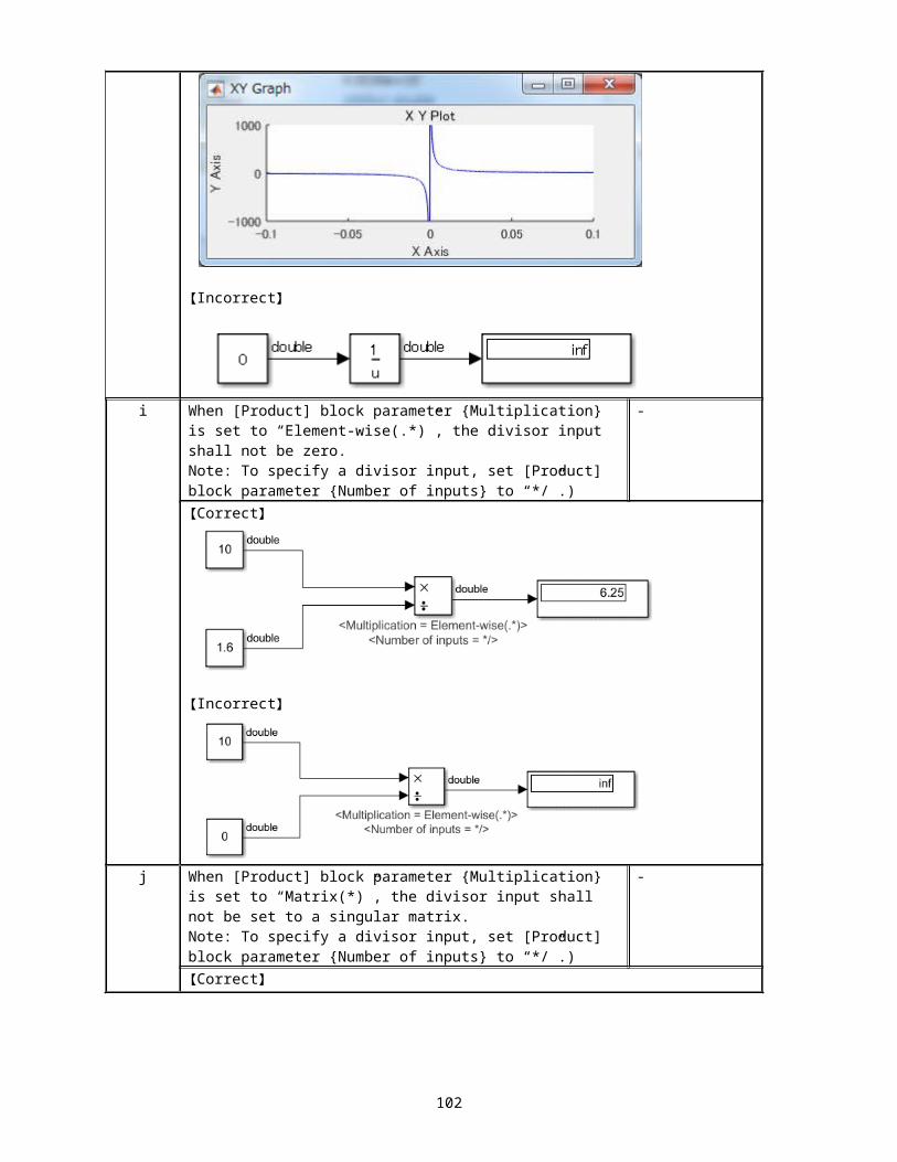
【Incorrect】[Inport] is not positioned on the left side of the diagram.
b [Outport] shall be positioned on the right side of the diagram, but can be moved to prevent the crossing of signals.
-
【Correct】[Outport] is positioned on the right side of the diagram.
102
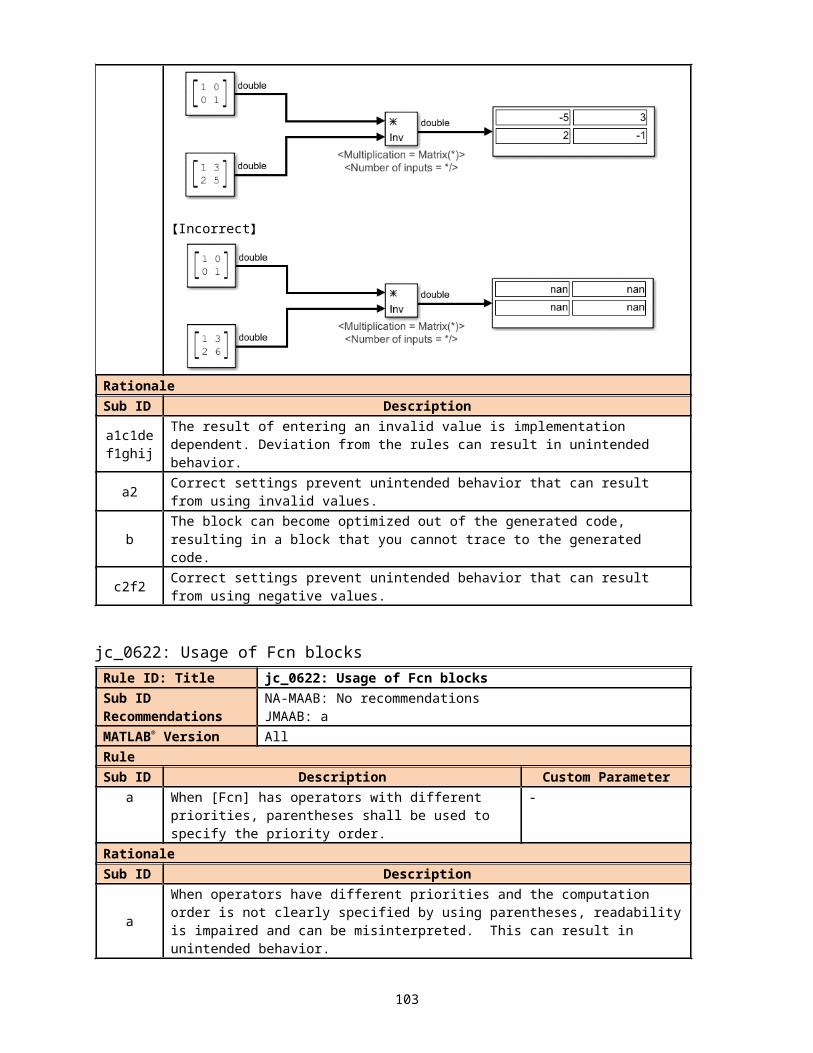
【Incorrect】[Outport] is not positioned on the right side of the diagram.
c Duplicate [Inport] shall be prohibited. -【Correct】
One [Inport] is used..
【Incorrect】 [Inport] is duplicated.
103
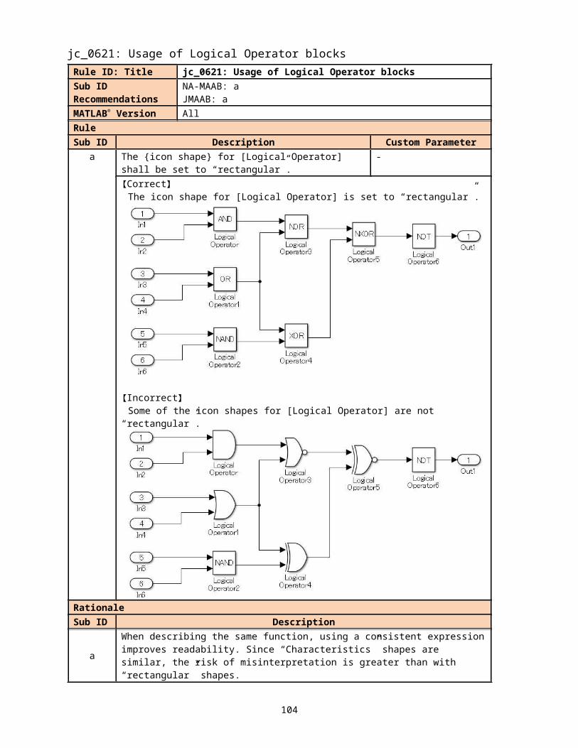
RationaleSub ID Description
abc Defined operation rules improve readability.
jc_0081: Inport/Outport block icon displayRule ID: Title jc_0081: Inport/Outport block icon displaySub ID Recommendations
NA-MAAB: aJMAAB: a
MATLAB® Version AllRuleSub ID Description Custom Parameter
a For [Inport] and [Outport], block parameter {Icon Display} shall be set to "Port number".
-
【Correct】The {icon display} for [Inport] and [Outport] is "Port number".
【Incorrect】The {icon display} for [Inport] and [Outport] is not "Port number".
RationaleSub ID Description
a Improves readability by displaying the port number of [Inport] and [Outport].
104
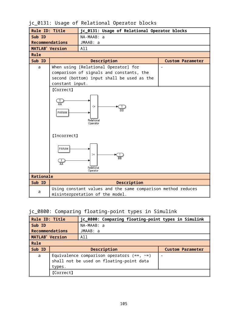
Allows for easy identification of port numbers that are within a subsystem. Prevents misconnections to hierarchized subsystems by displaying the block names
and making the names of signal lines to the [Inport] or [Outport] the same as the block names.
na_0011: Scope of Goto/From blocksRule ID: Title na_0011: Scope of Goto/From blocksSub ID Recommendations
NA-MAAB: aJMAAB: a
MATLAB® Version AllRuleSub ID Description Custom Parameter
a [Goto] block parameter {tag visibility} shall be set to “Local”.
-
RationaleSub ID Description
a
When hierarchies of [Goto] and corresponding [From] are different, the connection relationships can be difficult to understand.
Simulation errors can occur when hierarchies of [Goto] and corresponding [From] are different and a virtual subsystem changes to an Atomic subsystem.
jc_0161: Definition of Data Store Memory blocksRule ID: Title jc_0161: Definition of Data Store Memory blocksSub ID Recommendations
NA-MAAB: No recommendationsJMAAB: a, b
MATLAB® Version AllRuleSub ID Description Custom Parameter
a The smallest scope level shall be used to define [Data Store Memory].
-
b Only data required for execution and code generation shall be defined in [Data Store Memory].
-
RationaleSub ID Description
a Readability improves when usage is limited.b Unused [Data Store Memory] data can affect maintenance and operability.
jc_0141: Usage of Switch blocksRule ID: Title jc_0141: Usage of Switch blocksSub ID Recommendations
NA-MAAB: aJMAAB: a
MATLAB® Version AllRuleSub ID Description Custom Parameter
a The second [Switch] input condition shall be a logical type. [Switch] block parameter {Criteria for passing first input} shall be set to “u2~=0”.
-
RationaleSub ID Description
a It is easier to understand specifications when the configuration is applied by using
105
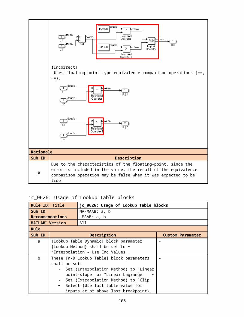
Simulink blocks rather than by writing operation expressions in blocks.
jc_0650: Block input/output data type with switching functionRule ID: Title jc_0650: Block input/output data type with switching functionSub ID Recommendations
NA-MAAB: aJMAAB: a
MATLAB® Version AllRuleSub ID Description Custom Parameter
a For blocks with switching functions ([Switch], [Multiport Switch], and [Index Vector]), the same data type shall be used for data ports and output ports.
-
【Correct】The data type for the data port and output port is the same.
【Incorrect】The data port and output port have different data types.
106
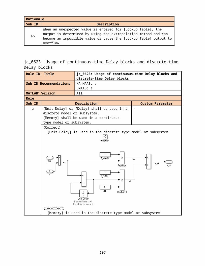
RationaleSub ID Description
a Prevents implicit data conversion.
jc_0630: Usage of Multiport Switch blocksRule ID: Title jc_0630: Usage of Multiport Switch blocksSub ID Recommendations
NA-MAAB: a, cJMAAB: a, b, c
MATLAB® Version AllRuleSub ID Description Custom Parameter
a [Multiport Switch] block parameter {Number of data ports} shall be two or more.
-
b The input to the [Multiport Switch] control port shall be an unsigned integer.
-
c When [Multiport Switch] block parameter {data port order}is set to "Specify indices", these block parameters shall be set: {Data port for default case} to “Additional data port”. {Diagnostic for default case} to “None”.
-
【Correct】
107
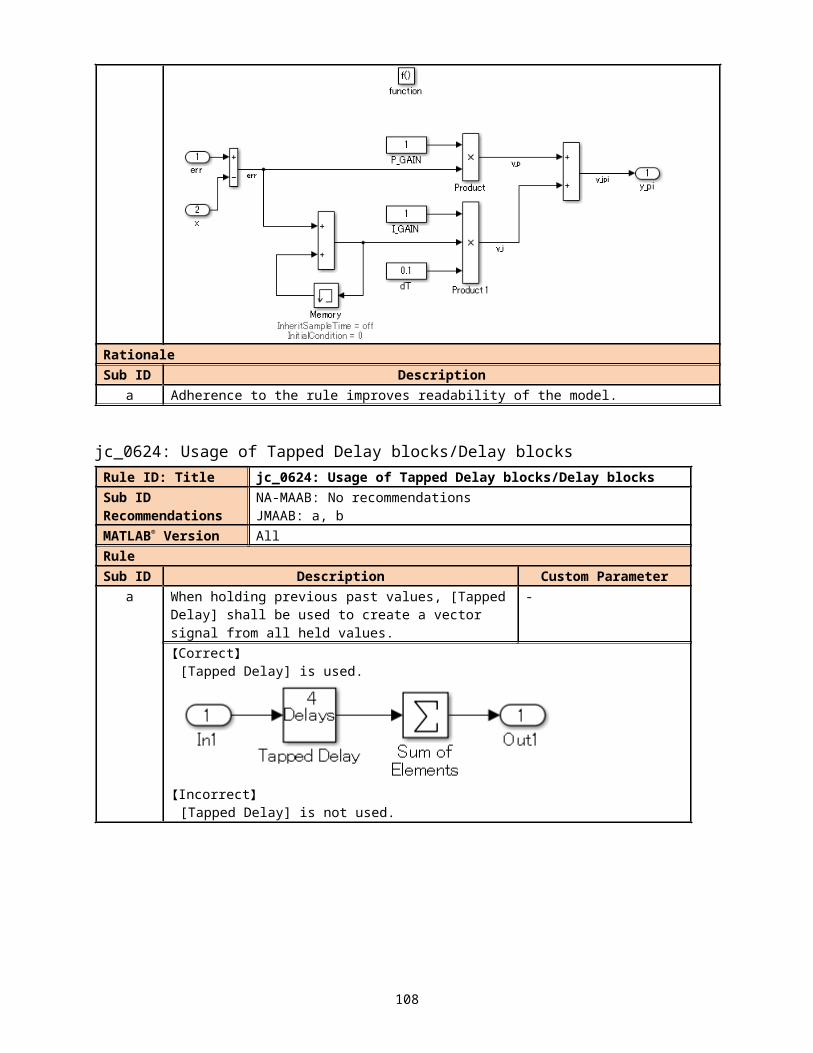
【Incorrect】
RationaleSub ID Description
a Unintended output can occur when there is only one data port because the block changes to extract scalars from vectors.
b
The control port is an input range that expects an integer value of zero or greater. When a signed or non-integer signal is connected to the control port, it can appear as a misconnection.
There is a possibility of data ports being unintentionally selected when negative or non-integer values are input.
c
When block parameter {Data port order} is set to “Specify indices”, any value that is input to [Multiport Switch], other than the index specified for the control port, is treated the same as the last value of the specified index. As a result, an unintended data port can be selected.
na_0020: Number of inputs to variant subsystemsRule ID: Title na_0020: Number of inputs to variant subsystemsSub ID Recommendations
NA-MAAB: aJMAAB: a, b
108
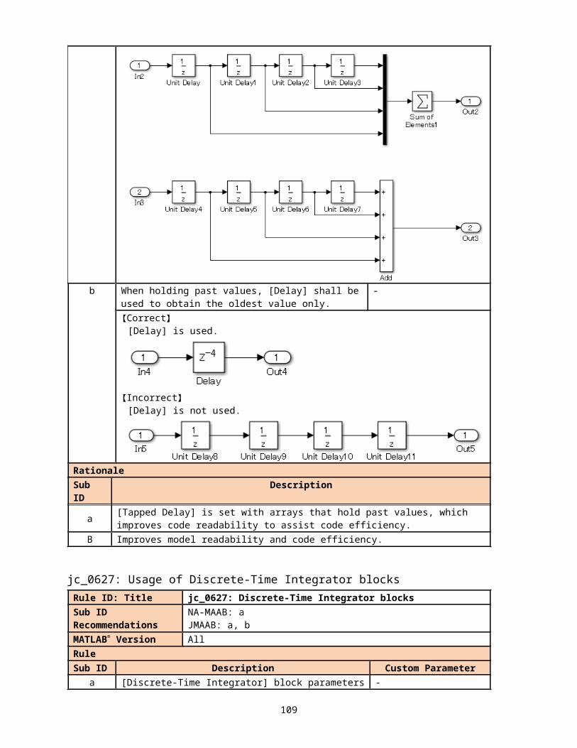
MATLAB® Version AllRuleSub ID Description Custom Parameter
a The number of inputs/outputs of a [Variant Subsystem] and its child subsystem or [Model Reference] shall be the same.
-
【Correct】The number of inputs to the child subsystem is the same.
【Incorrect】The number of inputs to the child subsystem is different.
b The number of inputs/outputs for [Model Variants] shall be that same as its referenced model.
-
【Correct】The number of inputs to the referenced model is the same as for [Model Variants] .
109
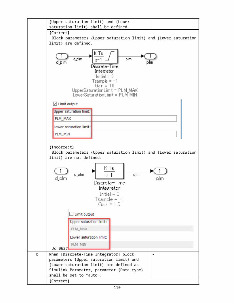
【Incorrect】The number of inputs to the referenced model is different than the inputs to [Model
Variants].
RationaleSub ID Description
ab Unconnected signals can be unintentionally overlooked when the number of inputs/outputs is different.
na_0036: Default variantRule ID: Title na_0036: Default variantSub ID Recommendations
NA-MAAB: a, bJMAAB: a, b
MATLAB® Version AllRuleSub ID Description Custom Parameter
a Variant subsystems shall be configured so that one subsystem is always selected. This is achieved by using one of these methods: Use the default variant for the variant. Define conditions that exhaustively cover all possible
values of the conditional variables. For example, define conditions for true and false values of a Boolean.
-
【Correct】A default variant is used.
【Correct】FUNC is a logical type.
110
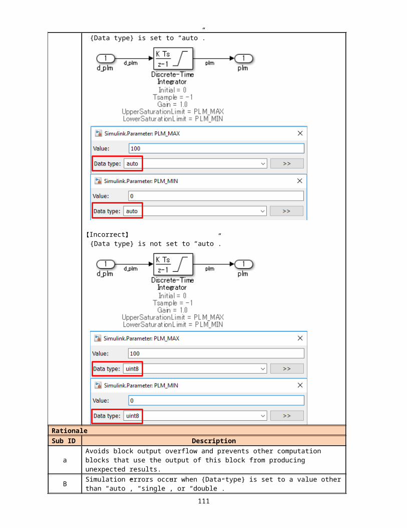
【Incorrect】An active subsystem will not exist when FUNC is not 1 or 2.
b Model variant conditions shall be set so that all values which can be applied to conditional variable signals are configured so that one subsystem is always selected. For example, a condition is prepared for the variable signal value being true, as well as false.
-
【Correct】The condition is set so that all values for the conditional variable are covered.
【Incorrect】An active subsystem will not exist when FUNC is not 1 or 2.
RationaleSub ID Description
ab Prevents the omission of conditions. There may not be an active subsystem when conditions are omitted.
na_0037: Use of single variable for variant conditionRule ID: Title na_0037: Use of single variable for variant conditionSub ID Recommendations
NA-MAAB: aJMAAB: a
MATLAB® Version AllRuleSub ID Description Custom Parameter
a Variant conditions shall be used to prohibit compound conditions that are formed from multiple variables.
Exception:When using default variants, conditional expressions
that are formed from multiple variables can be used.
-
【Correct】The variant condition is set by a single condition that is formed from multiple
variables.
111
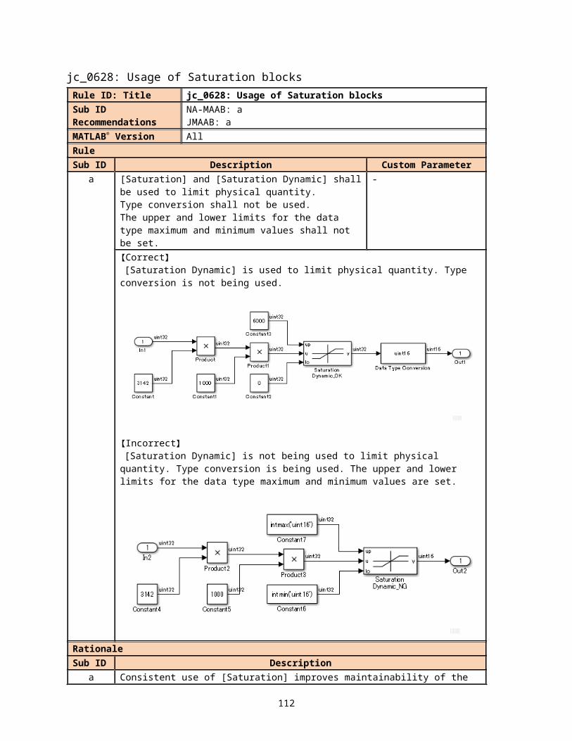
The usage of enumerated type variables is recommended in a condition equation. This example uses numerical values to improve readability.
【Incorrect】The variant condition is set by a compound condition that is formed from multiple
variables.
RationaleSub ID Description
a
Complicates the conditions, which makes it difficult to determine which subsystem will become active. This can result in conditions being omitted.
When conditions are omitted, there is a risk that there may not be an active subsystem.
4. Stateflow
4.1. Stateflow blocks/data/events
db_0122: Stateflow and Simulink interface signals and parametersRule ID: Title db_0122: Stateflow and Simulink interface signals and parametersSub ID Recommendations
NA-MAAB: aJMAAB: a
MATLAB® Version AllRuleSub ID Description Custom Parameter
a [Chart] parameter {Use Strong Data Typing with Simulink I/O} shall be selected so that strong data typing between a Stateflow chart and Simulink is permitted. Note: {Use Strong Data Typing with Simulink I/O} is available only when [Chart] property {Action Language} is set to “C”.
-
【Correct】Parameter {Use Strong Data Typing with Simulink I/O} is selected, so the input and
output are set to “uint8” type.
【Incorrect】Parameter {Use Strong Data Typing with Simulink I/O} is not selected, so the input
112
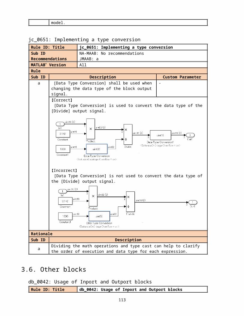
and output are set to “double” type.
RationaleSub ID Description
a
When {Use Strong Data Typing with Simulink I/O} is not selected, the Simulink signal data type that can input and output to [Chart] is set to “double” type. As a result, type conversion is required prior to input and after output, which increases the number of blocks and decreases readability.
When {Use Strong Data Typing with Simulink I/O} is not selected, the Simulink signal data type that can input and output to [Chart] is set to “double” type. However, input data of any type in [Chart] can connect directly with that signal.When these two signals have different data types, an implicit data type conversion occurs. By selecting {Use Strong Data Typing with Simulink I/O}, the implicit data type conversion does not take place and a data type inconsistency error is generated. This prevents misunderstandings due to differences in data type, thus improving readability.
db_0123: Stateflow port namesRule ID: Title db_0123: Stateflow port namesSub ID Recommendations
NA-MAAB: aJMAAB: Not supported
MATLAB® Version AllRuleSub ID Description Custom Parameter
a The name of a Stateflow input/output shall be the same as the corresponding signal.
Exception: Reusable Stateflow blocks can have different port names.
-
RationaleSub ID Description
a Improves readability. Code generation may not be possible.
db_0125: Stateflow local dataRule ID: Title db_0125: Stateflow local dataSub ID Recommendations
NA-MAAB: a, b, c, dJMAAB: a, b, c, d
MATLAB® Version AllRuleSub ID Description Custom Parameter
a Scope shall not define “Local” local data at the machine level.
-
【Correct】
113
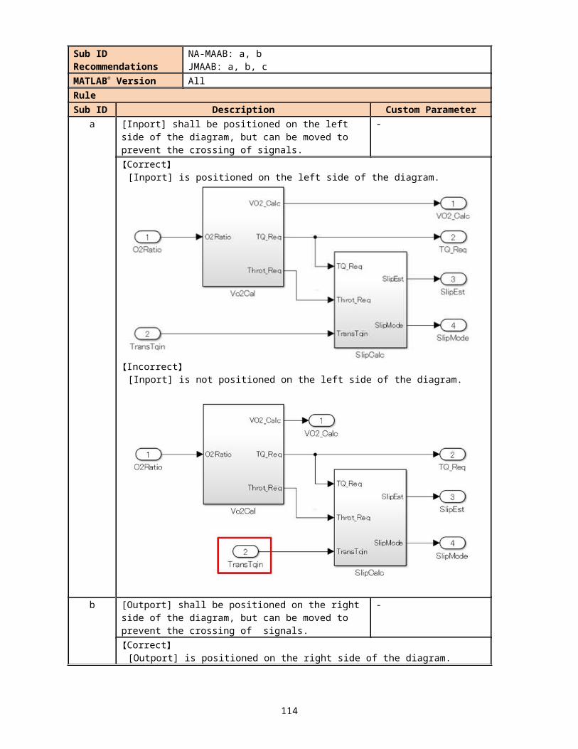
【Incorrect】Scope has set “Local” local data at the machine level.
b Scope shall not define “Constant” local data at the machine level.
-
【Correct】
114
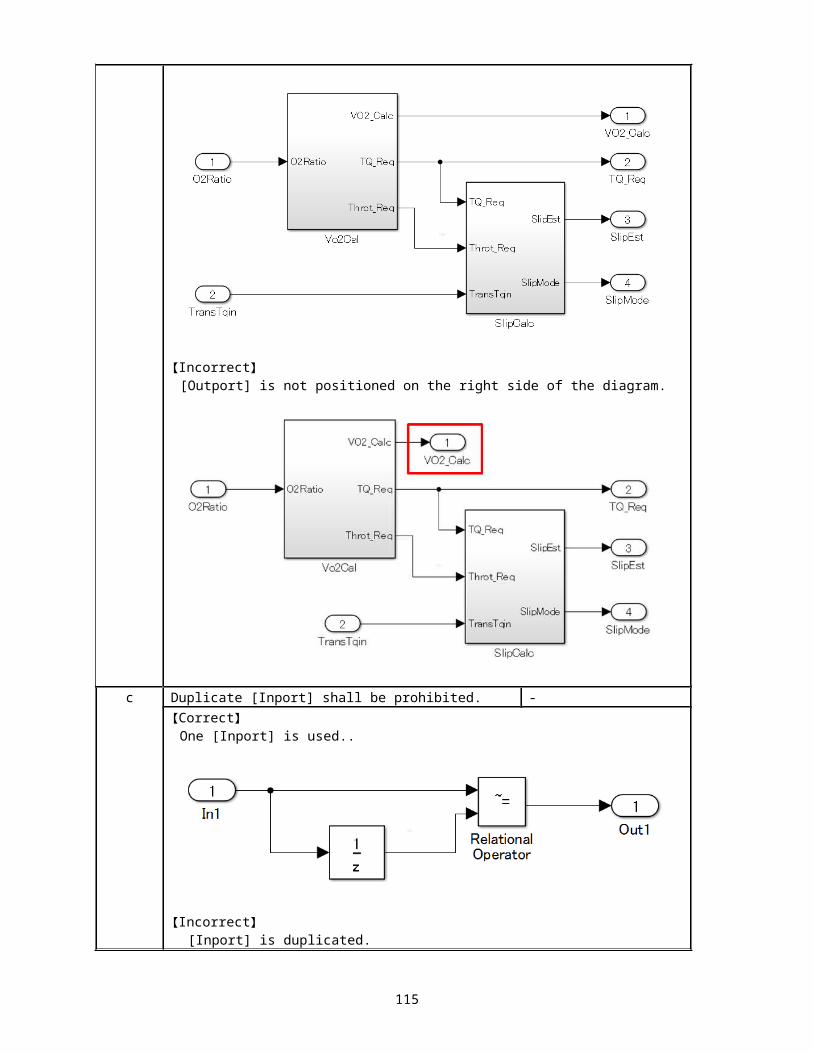
【Incorrect】Scope has set “Constant” local data at the machine level.
c Scope shall not define “Parameter” local data at the machine level.
-
【Correct】
115
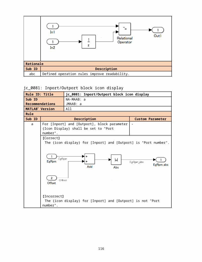
【Incorrect】Scope has set “Parameter” local data at the machine level.
d A Stateflow block with parent-child relationships shall not include local data with the same name.
-
【Correct】
116
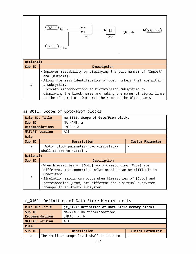
【Incorrect】A Stateflow block with parent-child relationships has local data with the same name.
RationaleSub ID Description
a When local data is defined at the machine level, it is shared with all blocks in the
model. The data will not behave like a local variable and can be influenced by any operation.
abc Adherence to the rules prevent the definition from disappearing when copying a Stateflow block to another model.
d When a Stateflow block with parent-child relationships includes local data with the
same name, readability decreases due to lack of clarity with regard to the influence of the local data.
db_0126: Defining Stateflow eventsRule ID: Title db_0126: Defining Stateflow eventsSub ID Recommendations
NA-MAAB: aJMAAB: a
MATLAB® Version AllRuleSub ID Description Custom Parameter
a Stateflow events shall be defined by the smallest scope -
117
level in the Stateflow block being used.
【Correct】
【Incorrect】
RationaleSub ID Description
a Limiting use locations increases reliability.
118
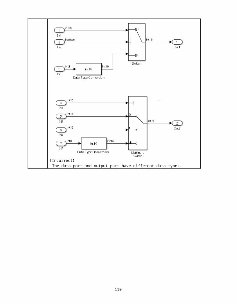
jc_0701: Usable number for first indexRule ID: Title jc_0701: Usable number for first indexSub ID Recommendations
NA-MAAB: a1/a2JMAAB: a1/a2
MATLAB® Version AllRuleSub ID Description Custom Parameter
a1 When [Chart] property {Action Language} is set to “C”, Stateflow data property {First index} shall be set to “0”.
-
【Correct】{First index} is set to “0”.
【Incorrect】{First index} is set to a combination of “0”, “1”, and “2”.
119
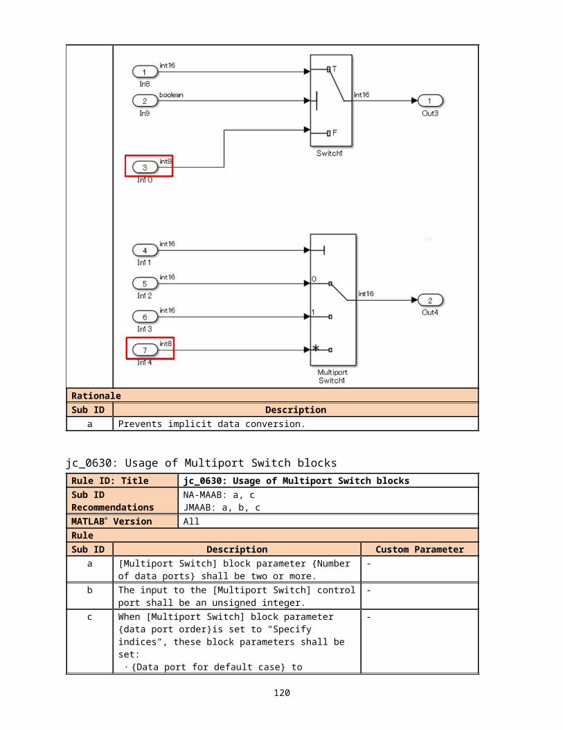
a2 When [Chart] property {Action Language} is set to “C”,
Stateflow data property {First index} shall be set to “1”.-
【Correct】The {First index} is set to “1”.
【Incorrect】
120
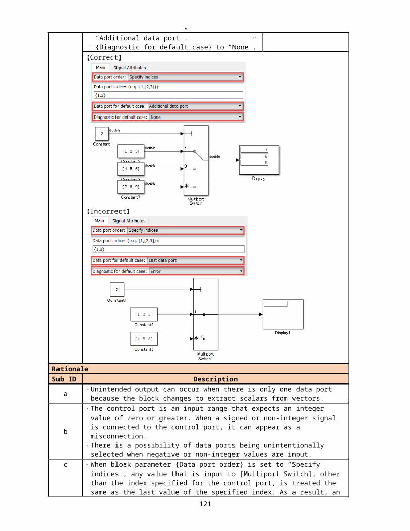
The {First index} is set to a combination of “0”, “1”, and “2”.
RationaleSub ID Description
a1 Logic becomes easier to understand when {First index} is uniform.
a2 Logic becomes easier to understand when {First index} is uniform. However, C
language is 0-based, which decreases the readability of the code as the index calculation process is 1-based. This is reflected in the generated code.
jc_0712: Execution timing for default transition pathRule ID: Title jc_0712: Execution timing for default transition pathSub ID Recommendations
NA-MAAB: aJMAAB: a
MATLAB® Version AllRuleSub ID Description Custom Parameter
a [Chart] property {Execute (enter) Chart At Initialization} shall not be selected.
-
RationaleSub ID Description
a
Using the same settings for each [Chart] prevents the model from being misinterpreted. Use caution when referencing an input signal using the default transition line when property {Execute (enter) Chart At Initialization} is selected. (See manual for further details)
121
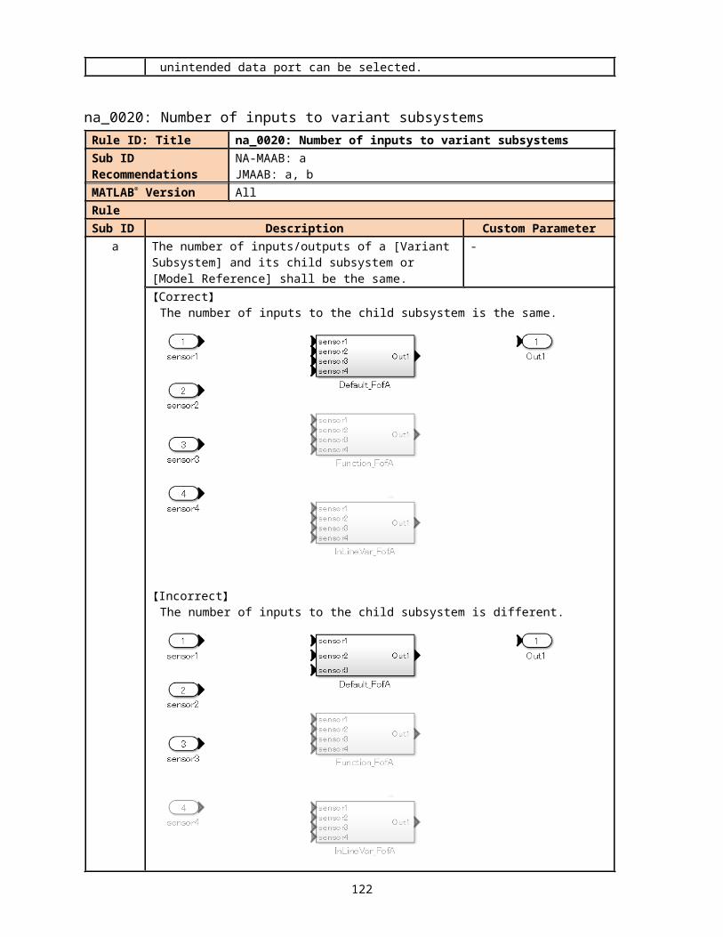
jc_0722: Local data definition in parallel statesRule ID: Title jc_0722: Local data definition in parallel statesSub ID Recommendations
NA-MAAB: aJMAAB: a
MATLAB® Version AllRuleSub ID Description Custom Parameter
a Local variables that are completed in one state shall be defined in that state.
-
【Correct】Local variables are defined in the state being used.
【Incorrect】
Local variables are not defined in the state being used.
122
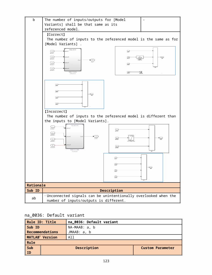
RationaleSub ID Description
a Readability and maintainability can be improved by explicitly limiting the valid range of the variables, thereby avoiding unintended references and changes.
4.2. Stateflow diagram
jc_0797: Unconnected transitions / states / connective junctionsRule ID: Title jc_0797: Unconnected transitions / states / connective junctionsSub ID Recommendations
NA-MAAB: a, bJMAAB: a, b
MATLAB® Version AllRuleSub ID Description Custom Parameter
a [Chart] shall not have unconnected transitions. -【Correct】
[Chart] does not have unconnected transitions.
【Incorrect】[Chart] has unconnected transitions.
123
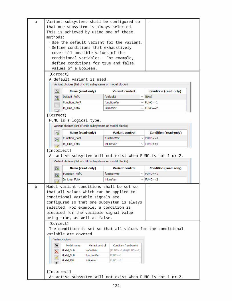
b [Chart] shall not have unconnected exclusive (OR) states and connective junctions without a transition source.
-
【Correct】[Chart] does not have unconnected exclusive (OR) states or connective junctions
without a transition source.
【Incorrect】[Chart] has unconnected exclusive (OR) states and connective junctions without a
transition source.
RationaleSub ID Description
124
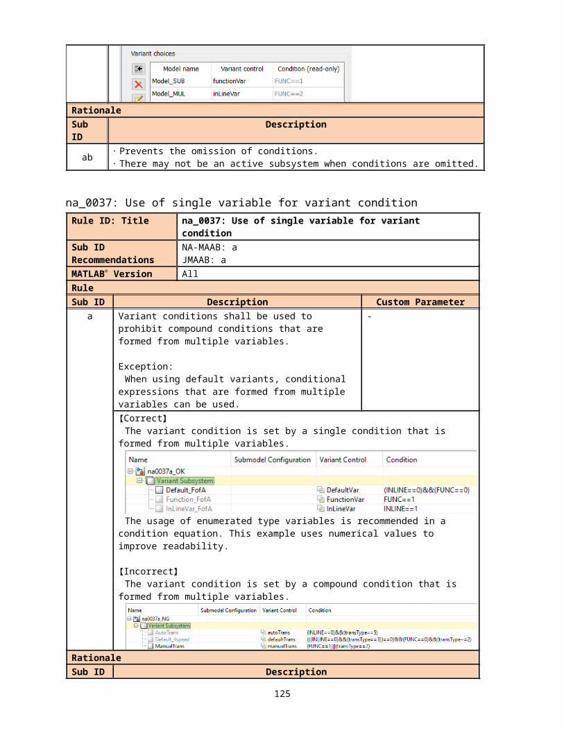
ab Unconnected transitions can result in adverse effects, such as misinterpretation of simulation results or failure to generate code.
db_0137: States in state machinesRule ID: Title db_0137: States in state machinesSub ID Recommendations
NA-MAAB: aJMAAB: a
MATLAB® Version AllRuleSub ID Description Custom Parameter
a When the {Decomposition} of the [Chart] or State is set to “OR (Exclusive)”, there shall be at least two states in the hierarchy.
-
【Incorrect】{Decomposition} of the [Chart] and State A is set to “OR(exclusive)”, but the hierarchy
contains only one state.
RationaleSub ID Description
a Redundant descriptions impair readability. Generated code includes unnecessary state variables.
jc_0721: Usage of parallel statesRule ID: Title jc_0721: Usage of parallel statesSub ID Recommendations
NA-MAAB: aJMAAB: a
MATLAB® Version AllRuleSub ID Description Custom Parameter
a Substates of parallel states shall not be parallel states. -【Correct】
125
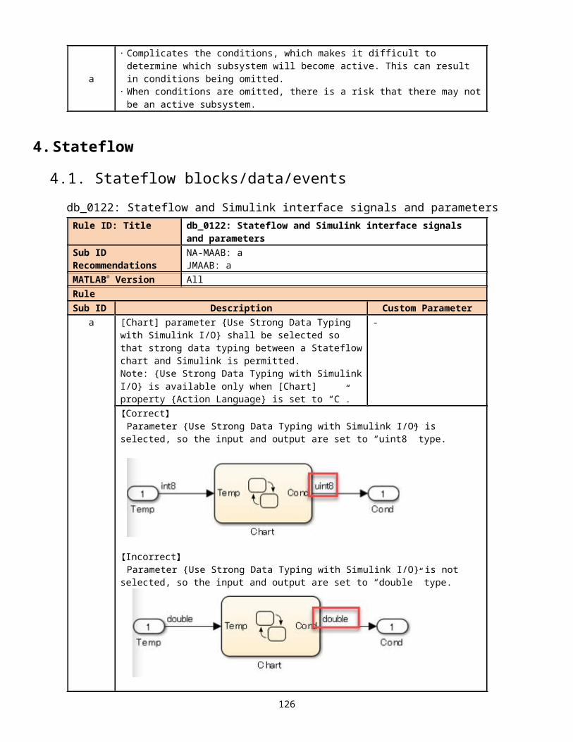
【Incorrect】Substates of parallel states are parallel states.
RationaleSub ID Description
a Behavior is not affected by nesting parallel states in a parent superstate. Hierarchization of the parallel state decreases readability.
db_0129: Stateflow transition appearanceRule ID: Title db_0129: Stateflow transition appearanceSub ID Recommendations
NA-MAAB: a, b, c, d, eJMAAB: a, b, c, d, e
MATLAB® Version AllRuleSub ID Description Custom Parameter
126
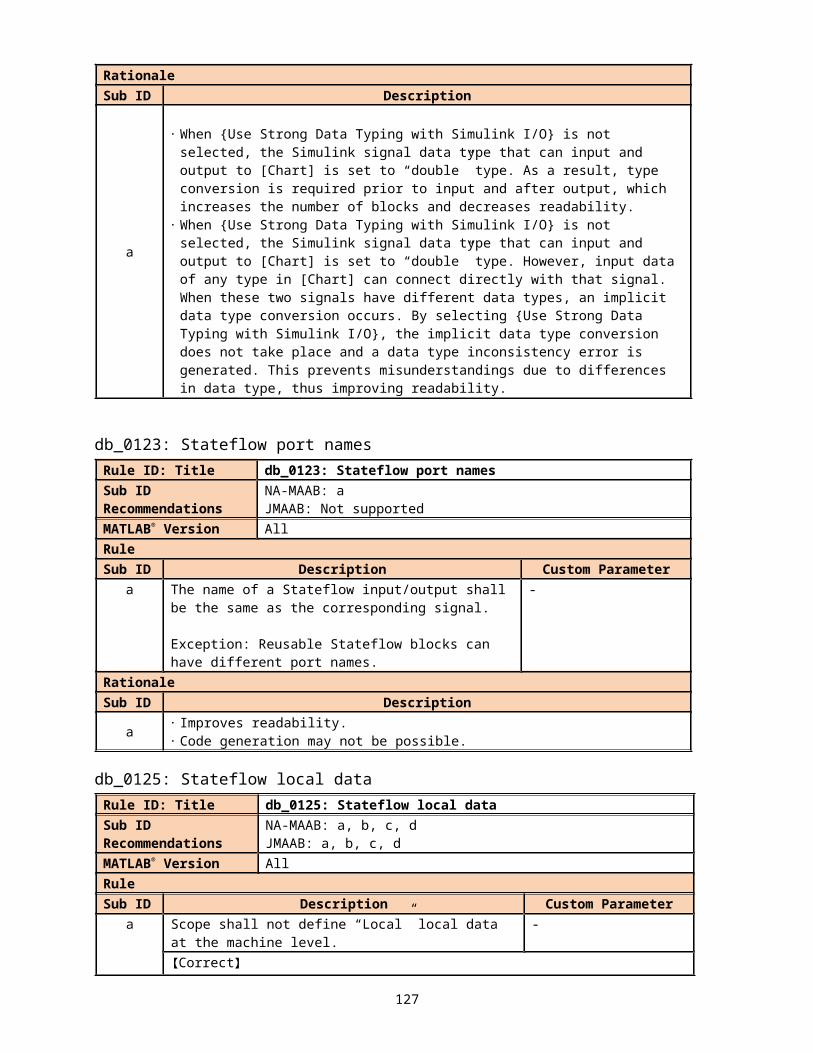
a Transition lines shall not cross over one another. -【Correct】
Transition lines do not cross.State003
State002State001
2
1
1
State004
{ action1;}
{ action2;}
2
[condition]1
2
【Incorrect】Transition lines cross.
b Transition lines shall not overlap other transition lines. -【Correct】
Transition lines do not overlap other transition lines.
【Incorrect】Transition lines overlap.
127
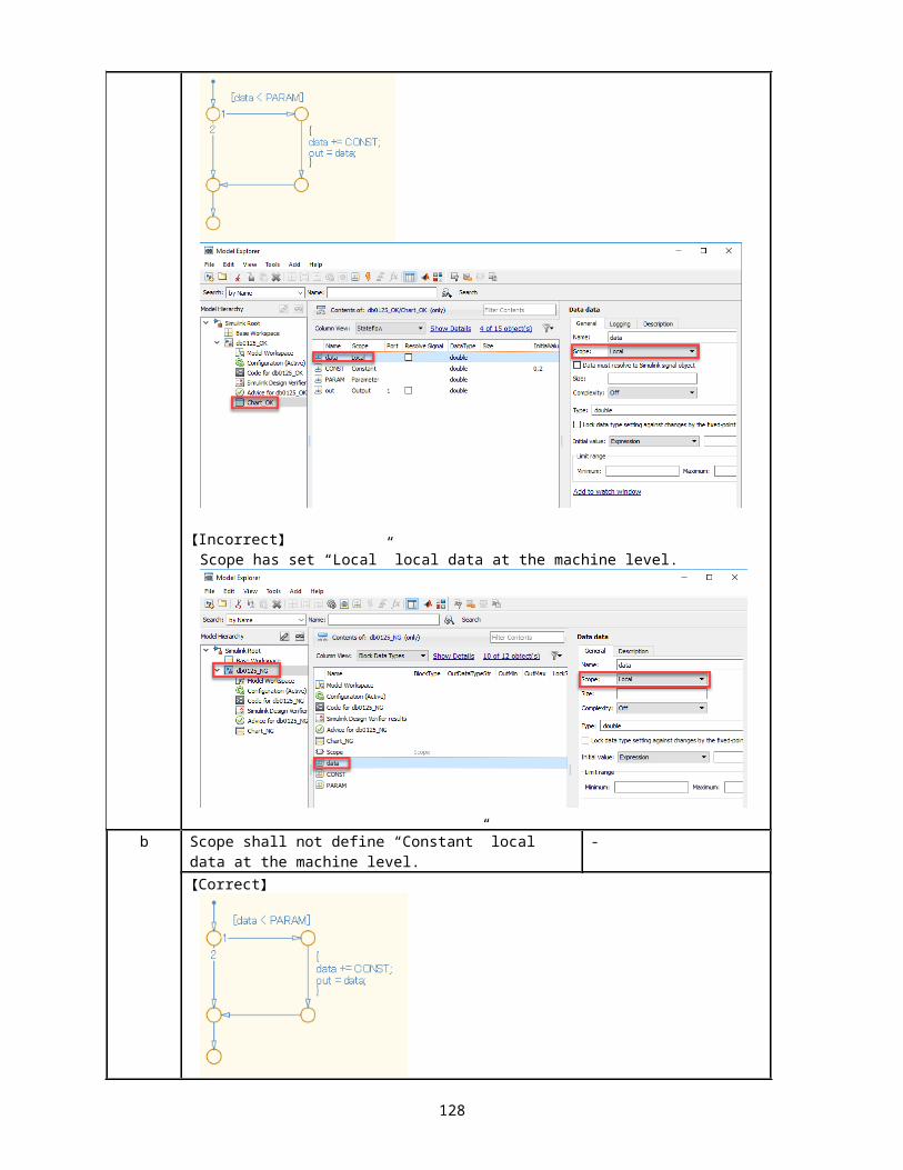
c Transition lines shall not cross over states. -【Correct】
Transition lines do not cross over states.
【Incorrect】Transition lines cross over states.
d Transition lines shall be drawn vertically or horizontally.Diagonal lines can be used for flow charts.
-
【Correct】Transition lines are drawn vertically or horizontally. Diagonal lines are used for flow
charts.
【Incorrect】Transition lines are not drawn vertically or horizontally.
128
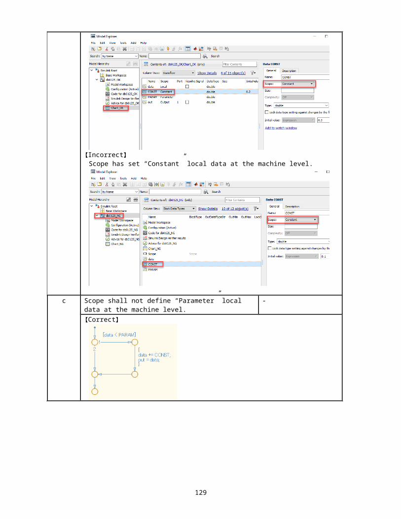
e Unnecessary connective junctions shall not be used. -【Correct】
Unnecessary connective junctions are not used.
【Incorrect】Unnecessary connective junctions are used.
RationaleSub ID Description
a Difficult to understand the relationship between states when transition lines cross.b Difficult to understand the relationship between states when transition lines overlap.
c Difficult to understand the relationship between states when transition lines cross over states.
d Consistent application of transition lines improves readability.
e Transitions can be difficult to understand when unnecessary connective junctions are used.
jc_0531: Default transitionRule ID: Title jc_0531: Default transitionSub ID NA-MAAB: a, b, c, d, e, f, g
129
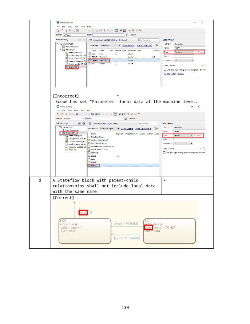
Recommendations JMAAB: a, b, c, d, e, f, gMATLAB® Version AllRuleSub ID Description Custom Parameter
a When {Decomposition} of [Chart] is “Exclusive (OR)”, the default transition shall connect at the top of the [Chart] block.
When {Decomposition} of the state is “Exclusive (OR)”, the default transition shall connect immediately beneath the state.
-
【Correct】The default transition line is connected at the top.
【Incorrect】The default transition line is not connected.
b When {Decomposition} is set to “Parallel (AND)”, the default transition line shall not be connected.
-
【Correct】{Decomposition} of the parent object for states AA and AB is set to “Parallel (AND)”,
which makes states AA and AB parallel states. The default transition line is not connected for these parallel states.
130
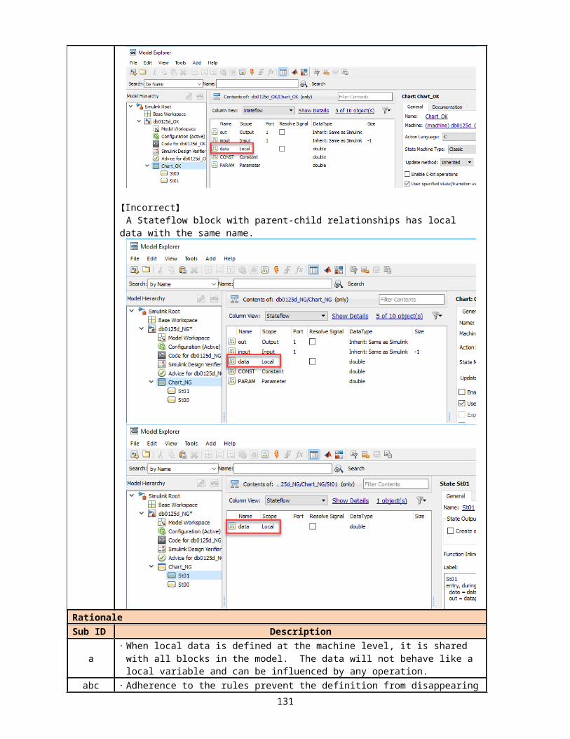
【Incorrect】A default transition line is connected for parallel state AA.
c A level shall not have multiple default transitions. -【Correct】The level does not have multiple default transitions.
【Incorrect】Multiple default transitions are included in the same level of state A.
131
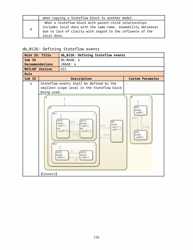
d Default transitions shall be connected directly and positioned vertically to the upper part of the state or connective junction.
-
【Correct】The default transition is connected vertically to the upper part of the state.
【Incorrect】The default transition of state A is not connected vertically to the upper part of the
state.
132
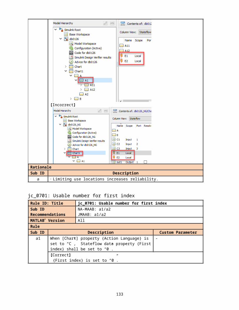
e The destination state or destination connective junction for the default transition shall be positioned to the top left in the same level.
-
【Correct】The default transition is positioned to the top left in the same level.
【Incorrect】The default transition of state AB is not positioned to the top left in the same level.
133
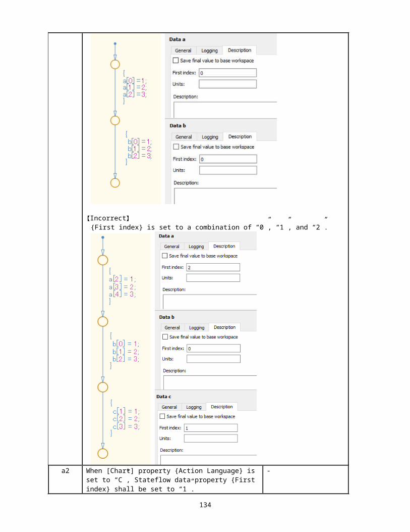
f Default transitions shall not extend beyond the boundaries of the state.
-
【Correct】The default transition is within the boundaries of the state.
【Incorrect】The default transition extends beyond the boundaries of the state.
134
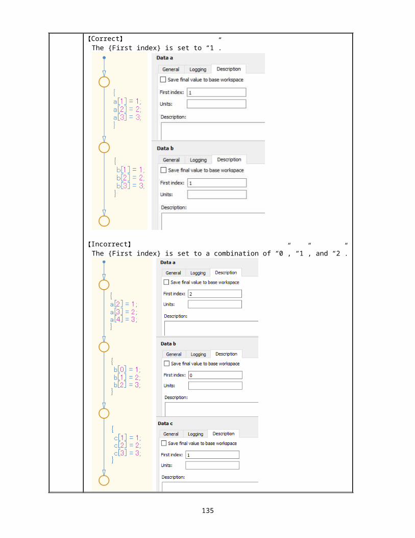
g Configuration parameter {No unconditional default transitions} shall be set to “Error” to ensure that in the transition path for the default transition, the path with the lowest priority is an unconditional transition.
-
【Correct】The path with the lowest priority in the transition path for the default transition is an
unconditional transition.
【Incorrect】The path with the lowest priority in the transition path for the default transition is not
an unconditional transition.
135
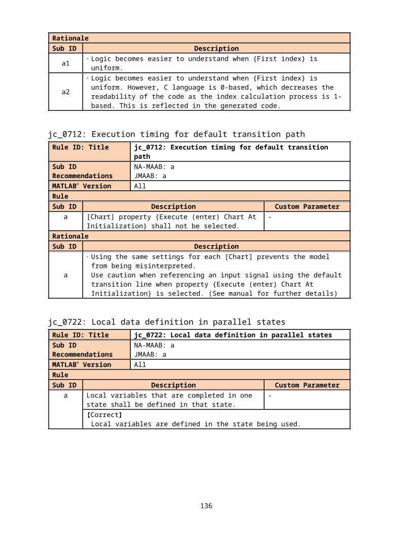
RationaleSub ID Description
a
Simulation errors can occur when a state chart does not include default transition lines.
When default transitions are included in a flow chart, it is impossible to determine whether this is intentional or through failure to insert them.
b Readability improves when there are no unnecessary default transitions.
c The state may not function as intended and produce a warning when multiple default transitions are included in the same level.
d Readability decreases when there are curves or variations in the angle or position of default transitions.
e Readability decreases when there are variations in the position of the transition destination state or transition destination connective junction for the default transition.
f Readability decreases when a default transition extends beyond the boundary of a state and intersects with state boundaries and expressions.
g When there is not an unconditional transition in the transition path of the default
transition, the transition destination disappears if all conditions of the transition path are not met. This can result in unintended behavior.
jc_0723: Prohibited direct transition from external state to child stateRule ID: Title jc_0723: Prohibited direct transition from external state to child
stateSub ID Recommendations
NA-MAAB: No recommendationsJMAAB: a
MATLAB® Version AllRuleSub ID Description Custom Parameter
a Transitions from one state directly to an external child state shall be prohibited.
-
【Correct】Transition from parent state to parent state.
136
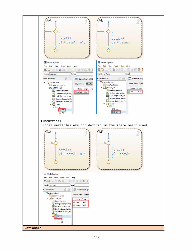
Transition from child state to another parent state.
【Incorrect】Direct transition from an external state to a child state in a different state.
137
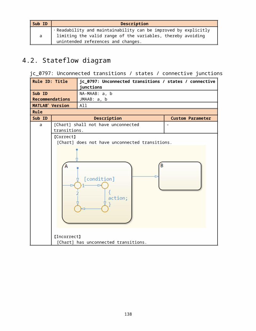
Direct transition from an external child state to a child state in a different state.
RationaleSub ID Description
a Direct transitions between child states can complicate the states and decrease readability.
jc_0751: Backtracking prevention in state transitionRule ID: Title jc_0751: Backtracking prevention in state transitionSub ID Recommendations
NA-MAAB: aJMAAB: a
MATLAB® Version AllRuleSub ID Description Custom Parameter
a Connective junctions shall not be used to separate complex conditions.
-
138
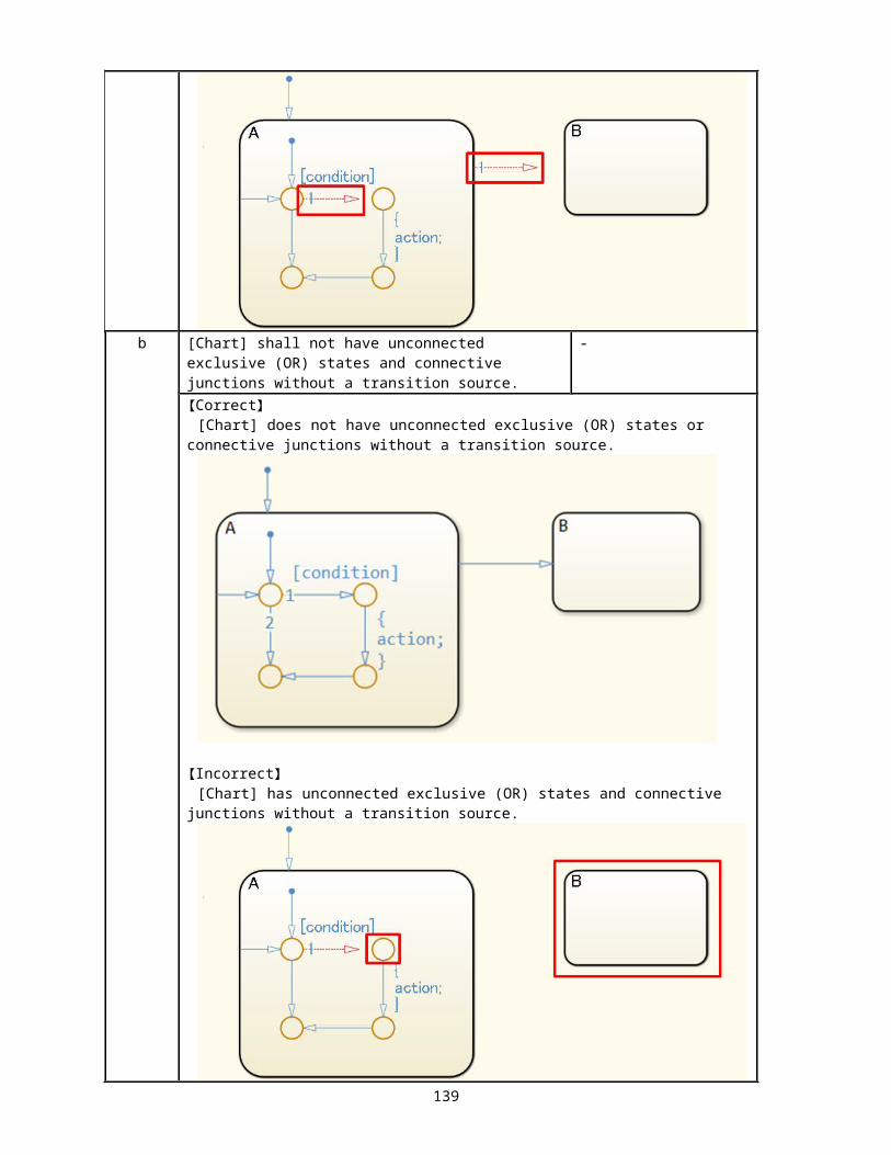
【Correct】Connective junctions are not used to separate complex conditions.
Aen,du: out = uint8(10);
Ben,du: out = uint8(20);[(!flg1) && (!flg2)]
[flg1 && flg2]
【Incorrect】Connective junctions are used to separate complex conditions.
RationaleSub ID Description
a Deviation from the rule can cause backtracking, which results in unintended behavior.
jc_0760: Starting point of internal transitionRule ID: Title jc_0760: Starting point of internal transitionSub ID Recommendations
NA-MAAB: aJMAAB: a
MATLAB® Version AllRuleSub ID Description Custom Parameter
a Internal transition lines shall start from the left edge of the state.
-
【Correct】The internal transition line begins at the left edge of the state.
139
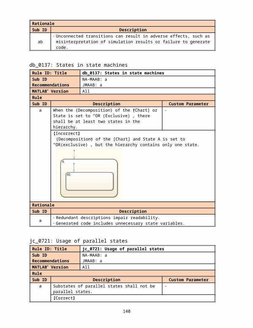
【Incorrect】The internal transition line does not begin at the left edge of the state.
140
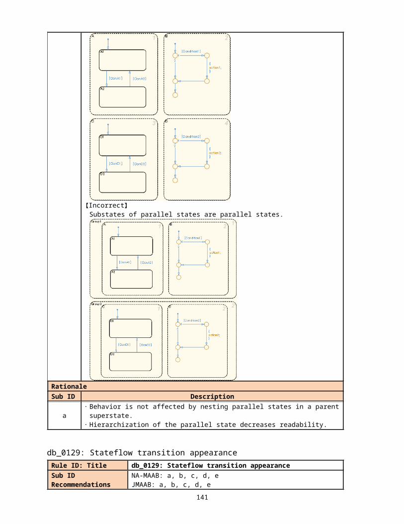
RationaleSub ID Description
a Adherence to the rule improves readability.
jc_0763: Usage of multiple internal transitionsRule ID: Title jc_0763: Usage of multiple internal transitionsSub ID Recommendations
NA-MAAB: a1/a2JMAAB: a1/a2
MATLAB® Version AllRuleSub ID Description Custom Parameter
a1 Multiple internal transitions shall not be used in a single state.
-
【Correct】
141
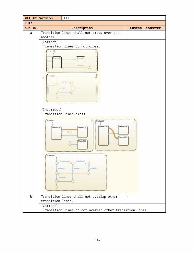
【Incorrect】
142
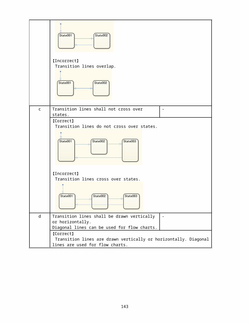
a2 When multiple internal transitions are used in a single state, they shall be listed from top to bottom in the order of execution.
-
【Correct】
143
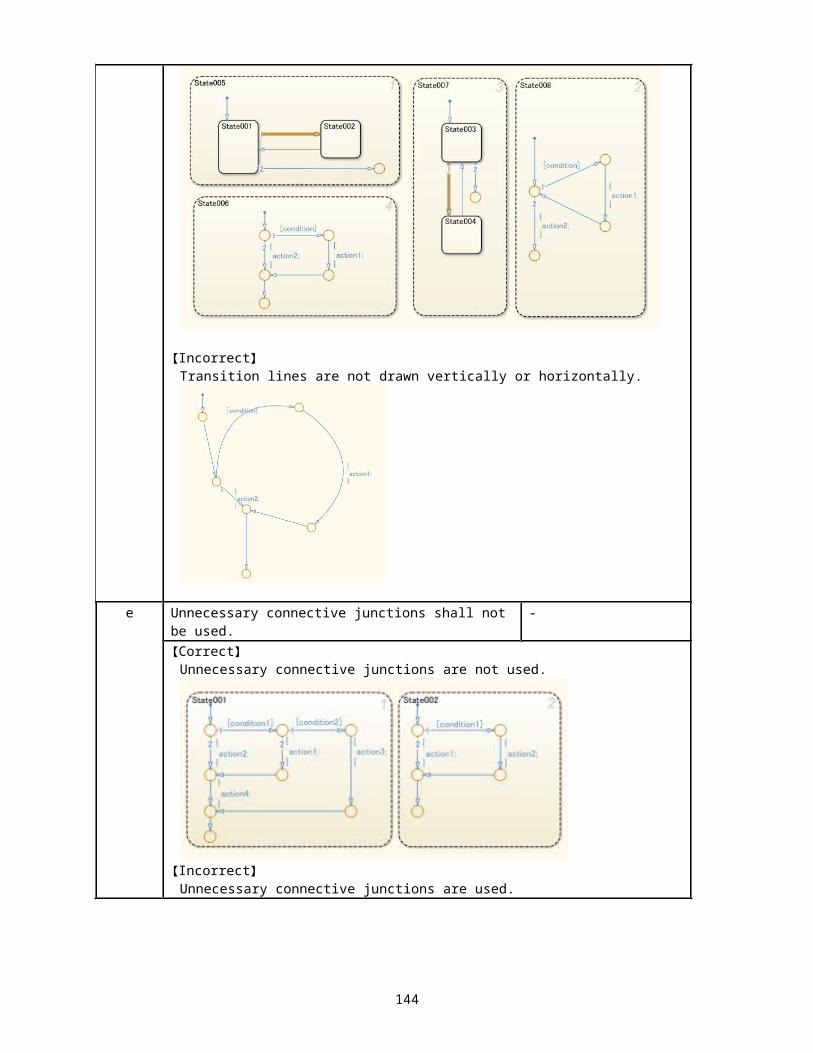
【Incorrect】
RationaleSub ID Description
a1 The number of transition conditions is unclear when multiple internal transitions are
used. By limiting the use of internal transitions to a single use, transitions are clearer and readability improves.
a2 Using multiple internal transitions can prevent transition lines from crossing and
simplifies state transitions. Arranging internal transitions in execution order improves readability.
jc_0762: Prohibition of state action and flow chart combinationRule ID: Title jc_0762: Prohibition of state action and flow chart combinationSub ID Recommendations
NA-MAAB: aJMAAB: a
MATLAB® Version All
144
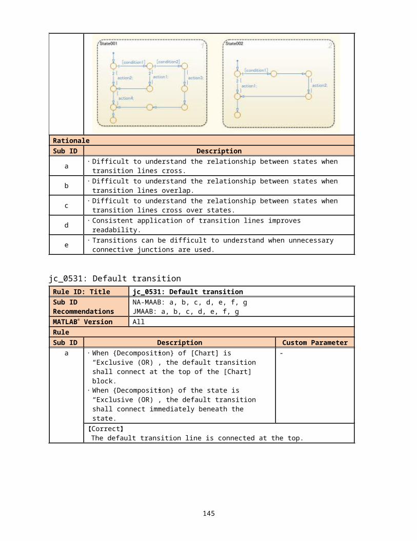
RuleSub ID Description Custom Parameter
a A state shall not include state actions (entry, during, or exit) and flow charts.
-
【Correct】Within the state, only one of either a State action or a flow chart is described.
【Incorrect】The state has both a state action and a flow chart.
145
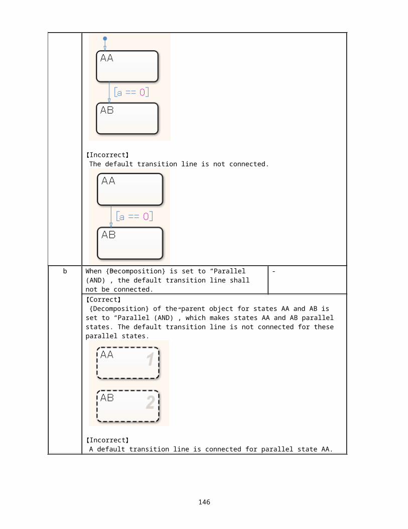
RationaleSub ID Description
a The execution order becomes difficult to understand, which decreases readability.
db_0132: Transitions in flow chartsRule ID: Title db_0132: Transitions in flow chartsSub ID Recommendations
NA-MAAB: a, bJMAAB: a, b
MATLAB® Version AllRuleSub ID Description Custom Parameter
a Transition actions shall not be used in flow charts. -【Correct】
Transition actions are not used.
146
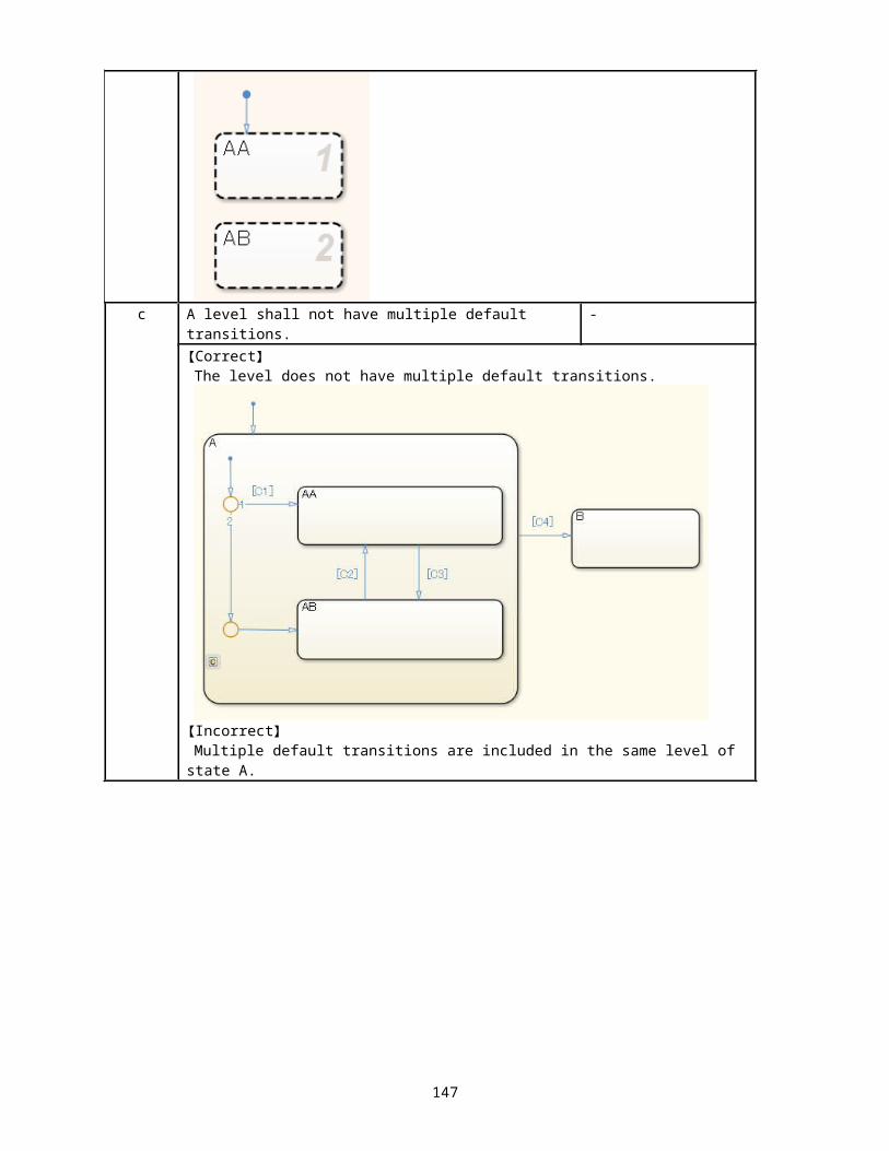
【Incorrect】Transition actions are used.
b In a flow chart, the condition shall be positioned on a horizontal transition line and the condition action shall be positioned on a vertical transition line.
Exception:Diagonal transition lines in loop constructs.
-
【Correct】The condition is positioned on a horizontal transition line and the condition action is
on a vertical transition line.
147
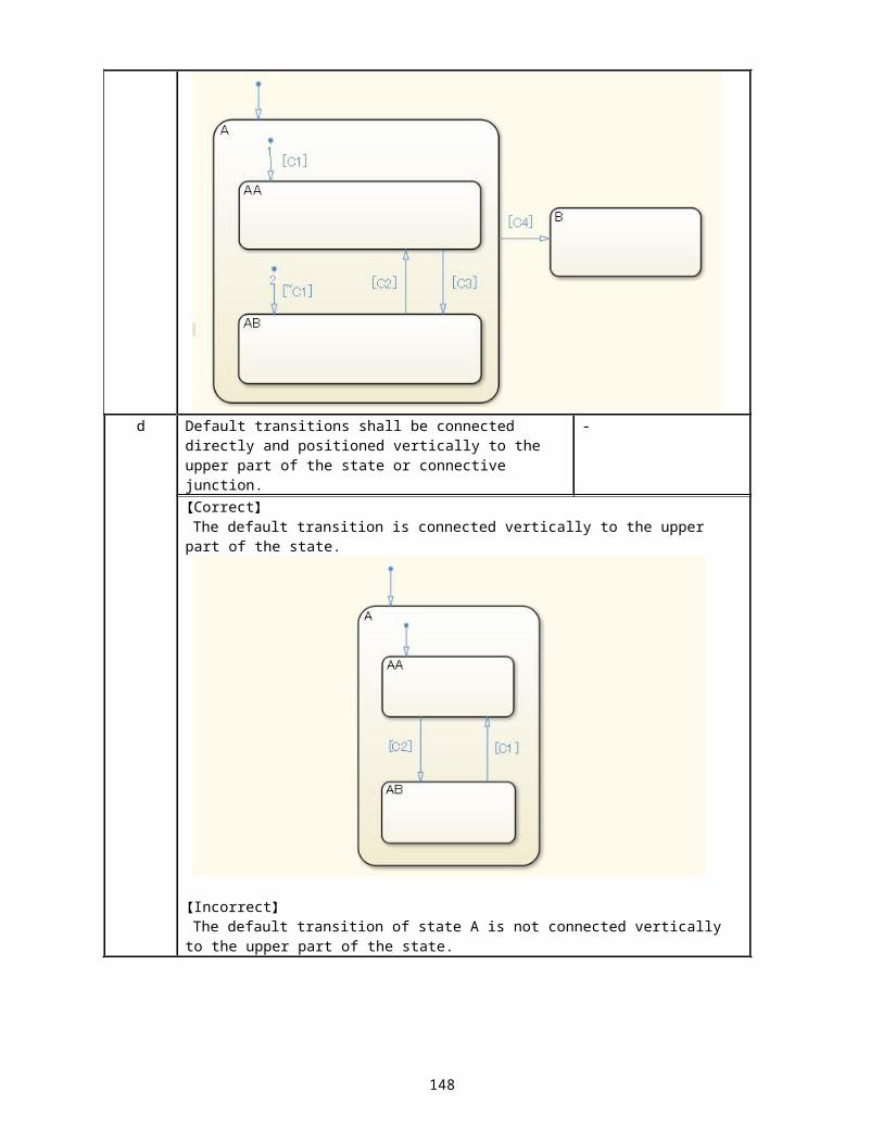
【Incorrect】The condition is positioned on a vertical transition line and the condition action is on a
horizontal transition line.
RationaleSub ID Description
a The transition action in a flow chart is not executed.b Consistent positioning of conditions and condition actions improves readability.
jc_0773: Unconditional transition of a flow chartRule ID: Title jc_0773: Unconditional transition of a flow chartSub ID Recommendations
NA-MAAB: a, bJMAAB: a, b
MATLAB® Version AllRuleSub ID Description Custom Parameter
a When a transition line with a transition condition originates from a connective junction, t unconditional transition line shall also begin from that junction.
-
【Correct】
148
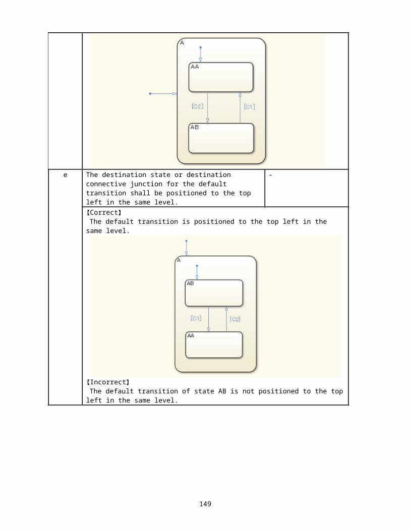
【Incorrect】0762
b The {execution order} for unconditional transitions shall be set to the last value.
-
【Correct】
149
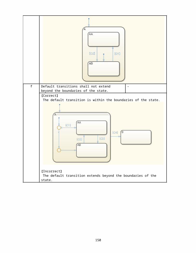
【Incorrect】The {execution order} for the unconditional transition line is not the last value.
RationaleSub ID Description
a Prevents unintended behavior that results from backtracking.
Setting an unconditional transition explicitly defines the behavior for when the condition is not met.
b Setting the unconditional transition to take precedence can prevent unintended behavior.
jc_0775: Terminating junctions in flow chartsRule ID: Title jc_0775: Terminating junctions in flow charts
150
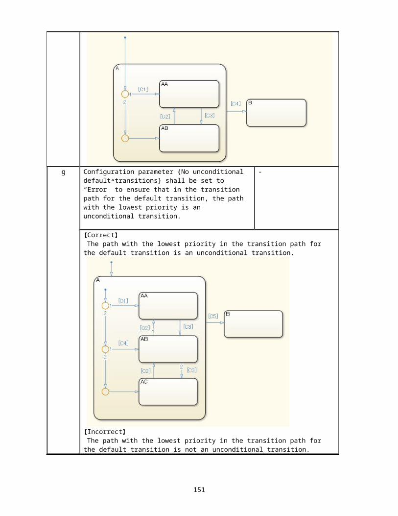
Sub ID Recommendations
NA-MAAB: a1/a2JMAAB: a1/a2
MATLAB® Version AllRuleSub ID Description Custom Parameter
a1 Only one terminating junction shall be used. -【Correct】
【Incorrect】There is more than one terminating junction.
a2 One terminating junction with a single unconditional transition as the input shall be used.
-
【Correct】
【Incorrect】There is more than one terminating junction and input.
151
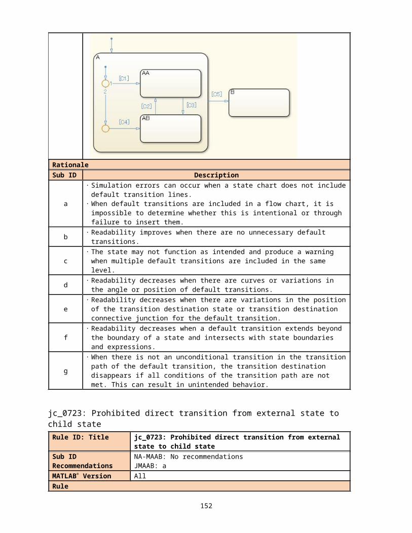
RationaleSub ID Description
a1a2 One terminating junction improves understanding of the logic end point. Using a consistent style for terminating junction improves readability.
jc_0738: Usage of Stateflow commentsRule ID: Title jc_0738: Usage of Stateflow commentsSub ID Recommendations
NA-MAAB: aJMAAB: a, b
MATLAB® Version AllRuleSub ID Description Custom Parameter
a When [Chart] parameter {Action Language} is set to “C”, /*...*/ comment nesting shall not be used.
-
【Correct】
【Incorrect】
b When [Chart] parameter {Action Language} is set to “C”, new line characters for comments /* */ shall not be used in the middle of a single comment.
-
【Correct】
152
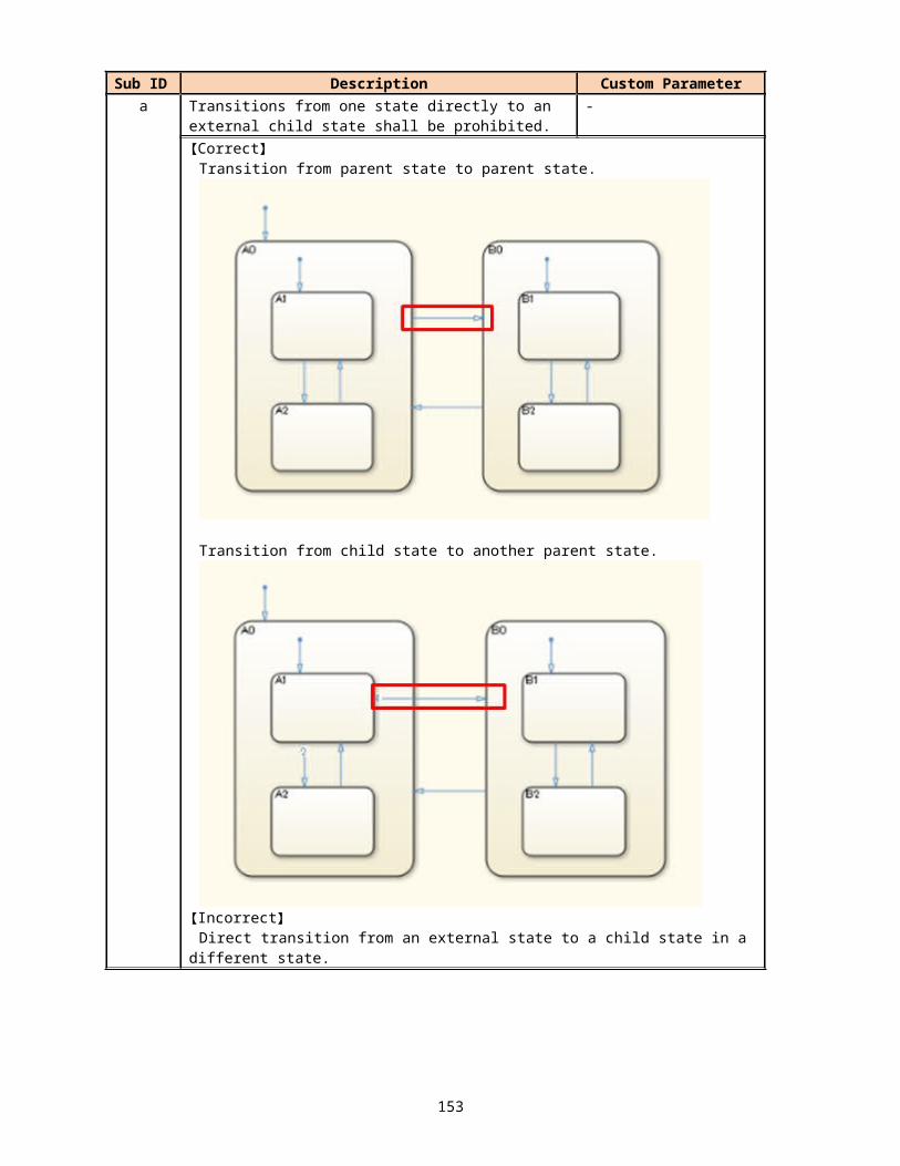
【Incorrect】
RationaleSub ID Description
a The compiler can misinterpret the comments as a program.
b
A line break in the middle of a comment makes it difficult to determine whether the part being edited is in the comment. There is also a possibility that the comment is nested.
When [Chart] property {Action Language} is set to “MATLAB”, comments must use %.
4.3. Conditional transition / Action
jc_0790: Action language of Chart blockRule ID: Title jc_0790: Action language of Chart blockSub ID Recommendations
NA-MAAB: No recommendationsJMAAB: a
MATLAB® Version AllRuleSub ID Description Custom Parameter
a [Chart] property {Action Language} shall be set to “C”. -【Correct】
{Action Language} is set to “C”.
153
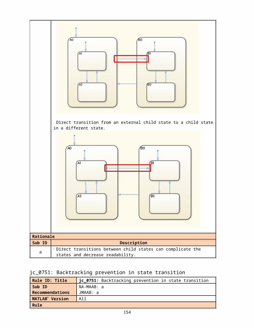
【Incorrect】{Action Language} is set to “MATLAB”.
RationaleSub ID Description
a
Using a consistent action language improves readability because there is not a difference in syntax.
Easier to maintain consistency between the model and the generated code when using C as the action language as compared to MATLAB.
Easier to understand the model for users who are familiar with the C programming language.
jc_0702: Use of named Stateflow parameters/constantsRule ID: Title jc_0702: Use of named Stateflow parameters/constantsSub ID Recommendations
NA-MAAB: aJMAAB: a
MATLAB® Version AllRuleSub ID Description Custom Parameter
154
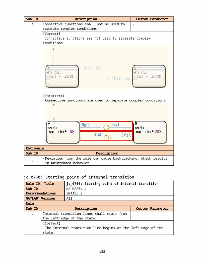
a [Stateflow] shall not use numeric literal.
Exceptions: Initial value is 0 Increment, decrement 1
-
【Correct】Numeric literals are not used.
【Incorrect】0711
RationaleSub ID Description
a
Only the modeler will understand the purpose of the value when numeric literals are used to write constants, which decreases readability.
Constants that are intended for calibration are generated in the code using numeric literals.
jm_0011: Pointers in StateflowRule ID: Title jm_0011: Pointers in StateflowSub ID Recommendations
NA-MAAB: aJMAAB: a
MATLAB® Version AllRuleSub ID Description Custom Parameter
a [Stateflow] shall not use pointer variables. -【Correct】
Pointer variables are not used.
155
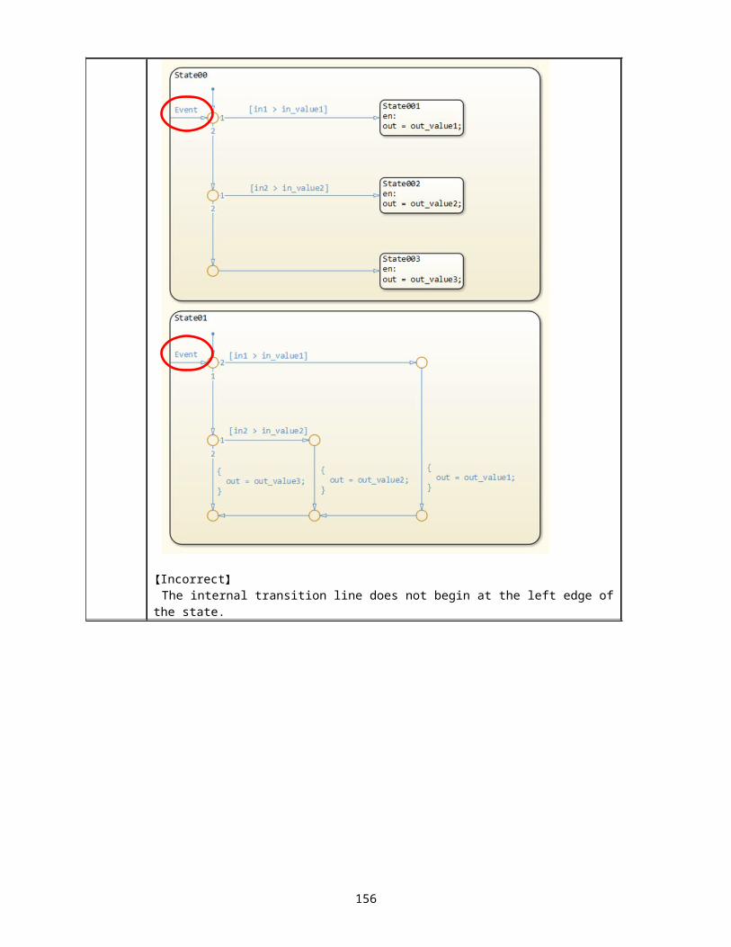
【Incorrect】Pointer variables are used.
RationaleSub ID Description
a Readability is impaired when pointer variables are used. Code generation may not be possible.
jc_0491: Reuse of Stateflow dataRule ID: Title jc_0491: Reuse of Stateflow dataSub ID Recommendations
NA-MAAB: aJMAAB: a
MATLAB® Version All
156
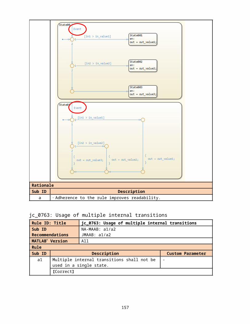
RuleSub ID Description Custom Parameter
a A variable shall not have multiple meanings (usages) in a single [Chart].
-
【Correct】A variable does not have multiple meanings (usages).
【Incorrect】Variables k and kk have multiple meanings (usages) in a single [Chart].
157
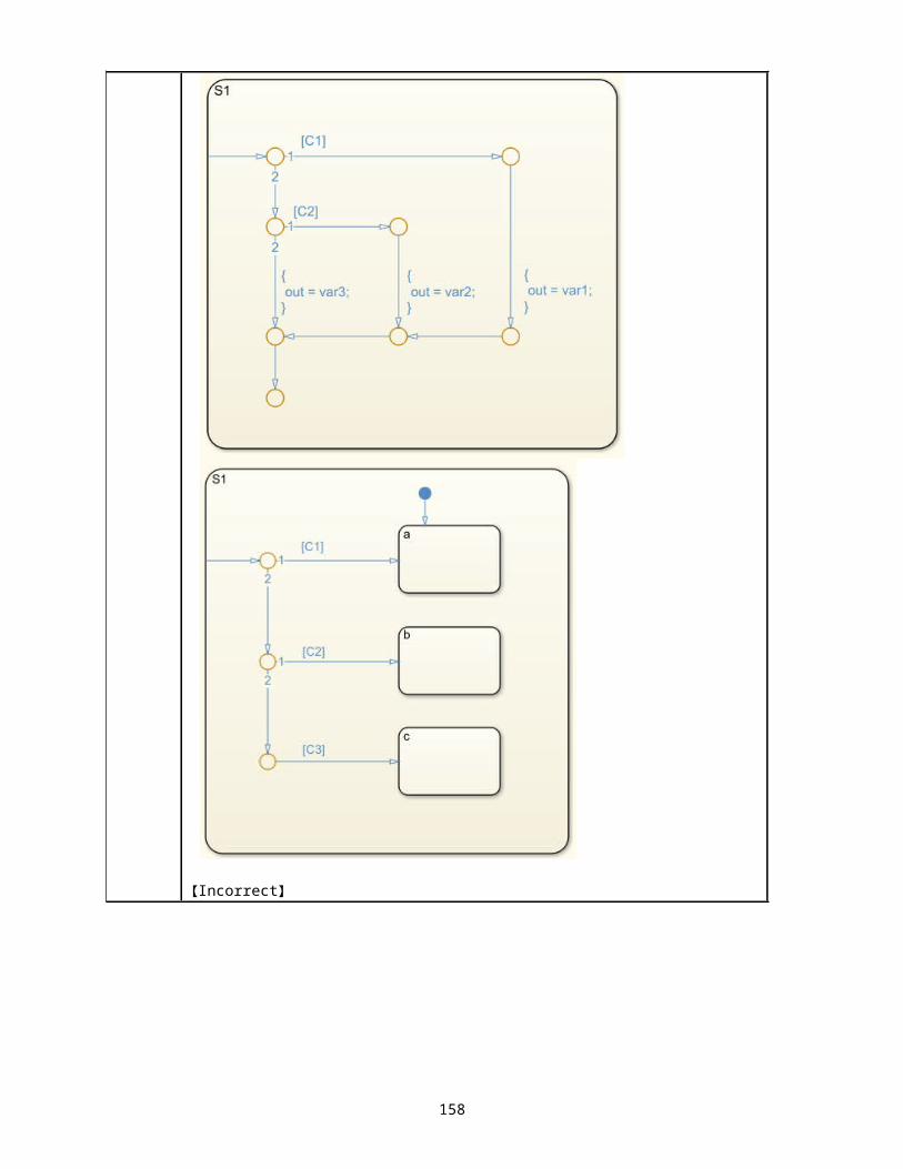
RationaleSub ID Description
a Variables can be misinterpreted when the variable name is different than the meaning of the numerical value that is assigned to the variable.
jm_0012: Usage restrictions of events and broadcasting eventsRule ID: Title jm_0012: Usage restrictions of events and broadcasting eventsSub ID Recommendations
NA-MAAB: No recommendationsJMAAB: a1/a2/a3
MATLAB® Version AllRule
158
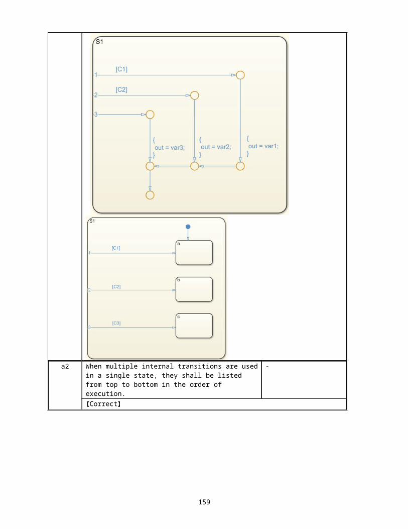
Sub ID Description Custom Parametera1 Stateflow events shall be used only in [Stateflow] output. -
【Correct】Event is used only in the [Stateflow] output.
【Incorrect】
Event is used other than in the [Stateflow] output.
a2 Send syntax send(event_name, state_name)shall be used to broadcast Stateflow events.
-
【Correct】Event is broadcast using the send syntax.
159
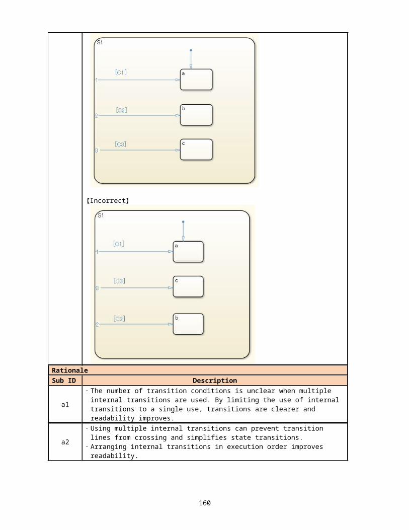
【Incorrect】The state that receives the broadcast has not been defined in the send syntax.
a3 Send syntax send(state_name.event_name)with the qualified event name shall be used to broadcast Stateflow events.
-
【Correct】The qualified event name is used in the event being broadcast.
160
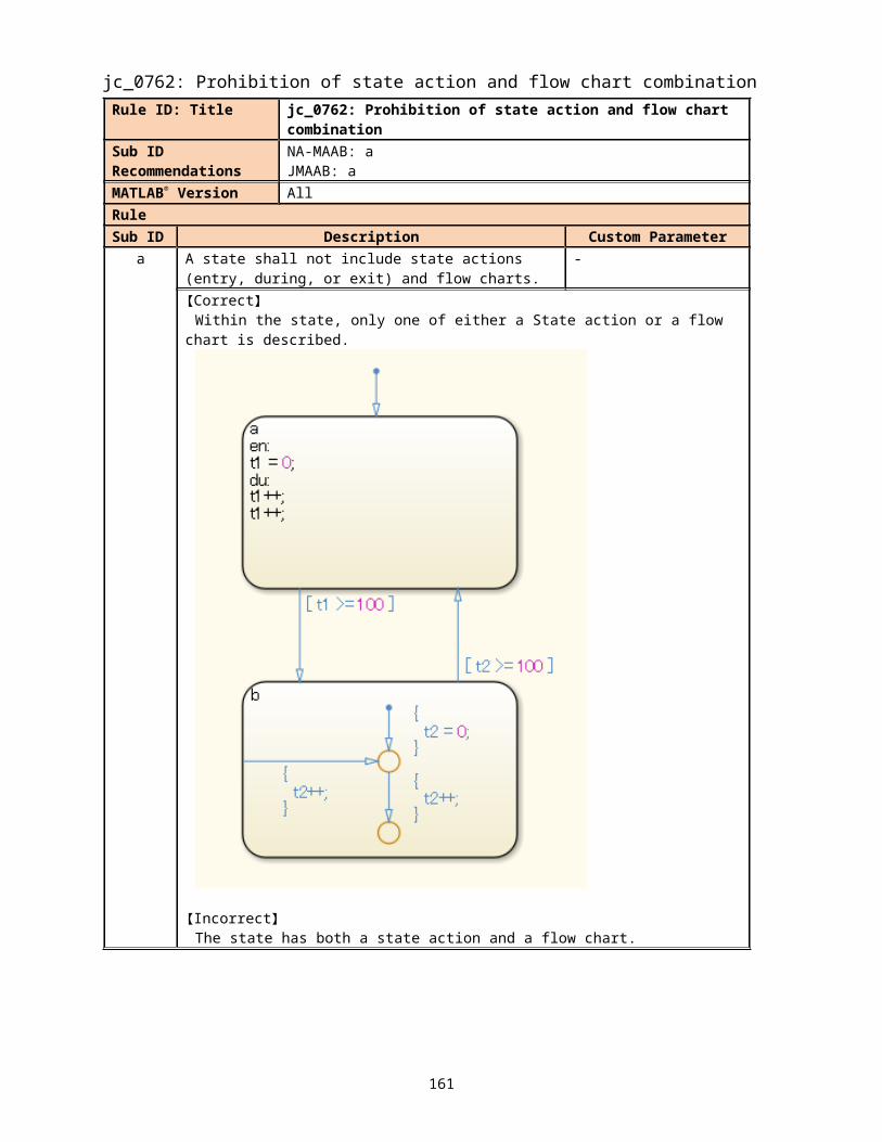
【Incorrect】The state that receives the broadcast has not been described in the send syntax.
RationaleSub ID Description
a1 Recursive processing in a chart is prevented by using Stateflow events in [Stateflow] output only.
a2a3 Improves readability because transitions that are triggered by events are clearly identified.
161
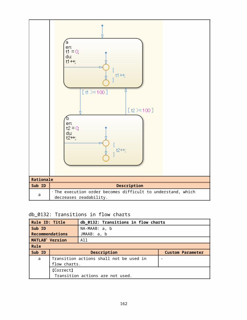
jc_0733: Order of state action typesRule ID: Title jc_0733: Order of state action typesSub ID Recommendations
NA-MAAB: a, bJMAAB: a, b
MATLAB® Version AllRuleSub ID Description Custom Parameter
a Basic state action types shall be stated in this order: entry (en)during (du)exit (ex)
-
【Correct 】 【Incorrect】 Order is en, du, ex. Not in en, du, ex order.
b Combined state action types shall be stated in this order:
entry (en)during (du) exit (ex)
-
【Correct 】 【Incorrect】Order is en, du, ex. Not in en, du, ex order.
162
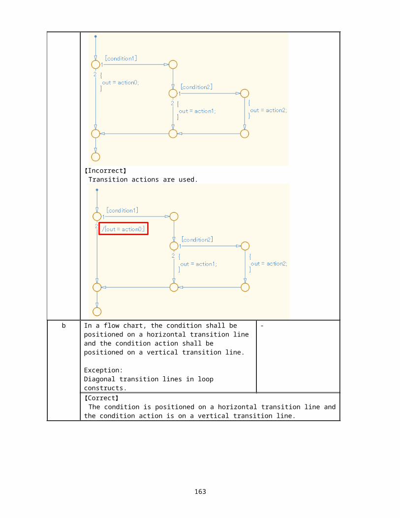
RationaleSub ID Description
ab Consistent modelling improves readability and maintainability.
jc_0734: Number of state action typesRule ID: Title jc_0734: Number of state action typesSub ID Recommendations
NA-MAAB: aJMAAB: a
MATLAB® Version AllRuleSub ID Description Custom Parameter
a State action types shall not describe the same thing more than twice.
-
【Correct 】 【Incorrect】
163
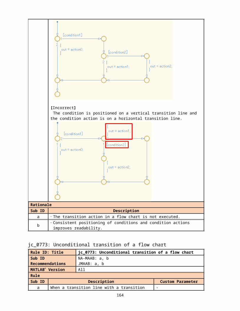
RationaleSub ID Description
a The execution order will differ depending on the order in which they are described. Execution order can be difficult to understand when the action type is described
multiple times.
jc_0740: Limitation on use of exit state actionRule ID: Title jc_0740: Limitation on use of exit state actionSub ID Recommendations
NA-MAAB: No recommendationsJMAAB: a
MATLAB® Version AllRuleSub ID Description Custom Parameter
a State action type exit(ex) shall not be used. -【Correct】
【Incorrect】This example illustrates how the model behavior in [Chart] is misinterpreted. It
appears that TBD is output when state action type exit(ex) is used, but it is in fact being overwritten by the state action type entry of the transition destination state. It is not outputted by [Chart].
RationaleSub ID Description
a Execution timing can be difficult to understand when state action type exit(ex) is used
in combination with a conditional action, a transition action, or state action type entry(en). This can result in misinterpretation of the model behavior.
jc_0741: Timing to update data used in state chart transition conditionsRule ID: Title jc_0741: Timing to update data used in state chart transition
conditionsSub ID Recommendations
NA-MAAB: No recommendationsJMAAB: a
MATLAB® Version AllRuleSub ID Description Custom Parameter
a Variables that are used in a state transition condition shall not use “during” to perform an update.
-
【Correct】The update is not performed by using “during”.
164
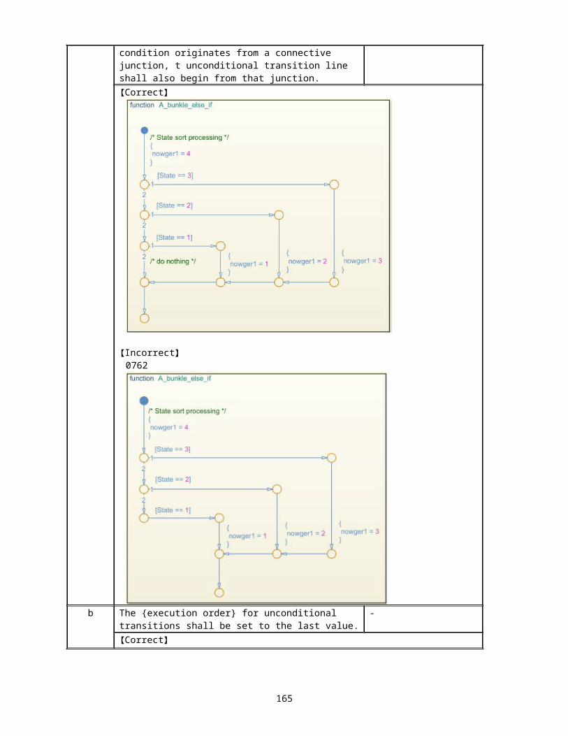
【Incorrect】The update is performed by using “during”.
RationaleSub ID Description
a The execution order of the transition condition and implement of “during” can be difficult to understand, which increases the risk of errors.
jc_0772: Execution order and transition conditions of transition linesRule ID: Title jc_0772: Execution order and transition conditions of transition
linesSub ID Recommendations
NA-MAAB: aJMAAB: a
MATLAB® Version All
165
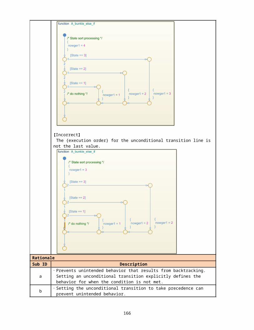
RuleSub ID Description Custom Parameter
a All transition paths shall be executable.
(R2011b to R2016a) Configuration parameter {Transition shadowing} shall be set to “error”.
(R2016b and later) Configuration parameter {Unreachable execution path] shall be set to “error”.
-
【Correct】
【Incorrect】Execution order 1 is an unconditional transition and conditional expression [C1] is
described in execution condition 2.
【Correct】Includes a state transition.
166
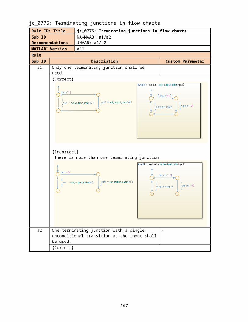
【Incorrect】Includes state transition. The unconditional transition line is higher in the execution order than the conditional transition line.
RationaleSub ID Description
a An unconditional transition that is in any position other than the last in the execution
order causes the subsequent transition to be a dead path, which results in unintended simulation behavior.
jc_0753: Condition actions and transition actions in StateflowRule ID: Title jc_0753: Condition actions and transition actions in StateflowSub ID Recommendations
NA-MAAB: a1/a2JMAAB: a1/a2
MATLAB® Version AllRuleSub ID Description Custom Parameter
a1 Transition actions shall not be used in a state chart. -【Correct】
167
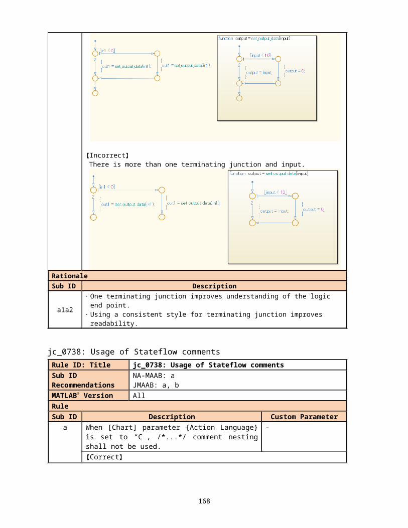
Only a condition action is used in the state chart.
【Incorrect】A transition action is used in the state chart.
a2 Condition actions and transition actions shall not be combined in the same [Chart].
-
【Correct】Either a condition action or a transition action can be used in a [Chart].(The following diagram illustrates a transition action.)
168
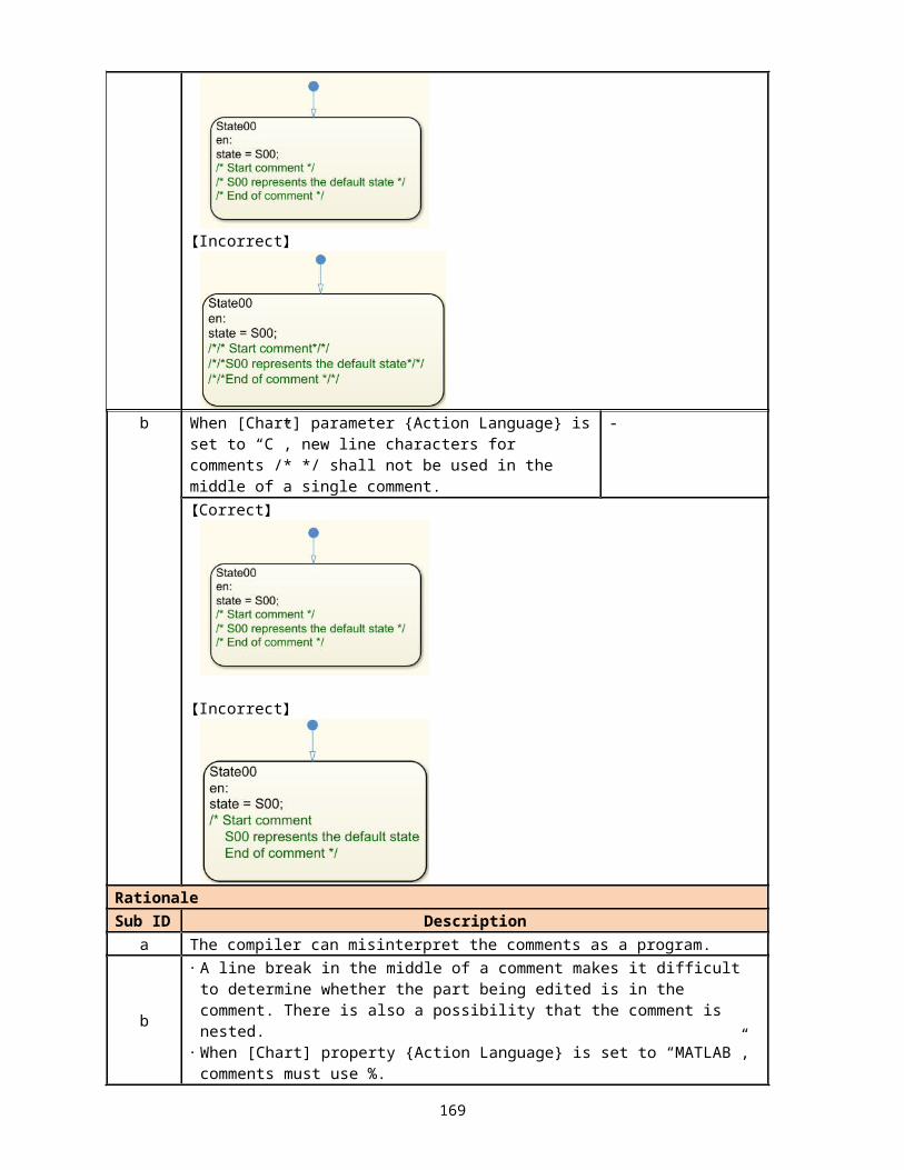
【Incorrect】[Chart] 0774
RationaleSub ID Description
a1 Prevents confusion with a condition action, thus improving readability.
a2 A condition action executes upon entering a transition. A transition action executes
after determining whether it can transition to the next state. Adherence to the rule prevents confusion between a conditional action and a transition action.
jc_0711: Division in StateflowRule ID: Title jc_0711: Division in StateflowSub ID Recommendations
NA-MAAB: No recommendationsJMAAB: a1/a2
MATLAB® Version AllRuleSub ID Description Custom Parameter
a1 Variables, constants, or parameters in a Stateflow block shall not be used to perform division operations.
-
【Correct】
169
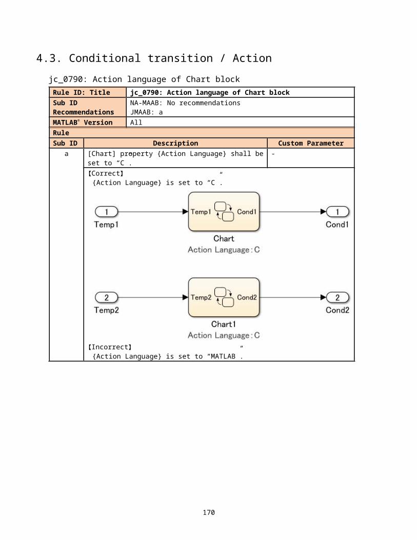
Division is performed outside of [Chart].
【Incorrect】Division occurs within [Chart].
170
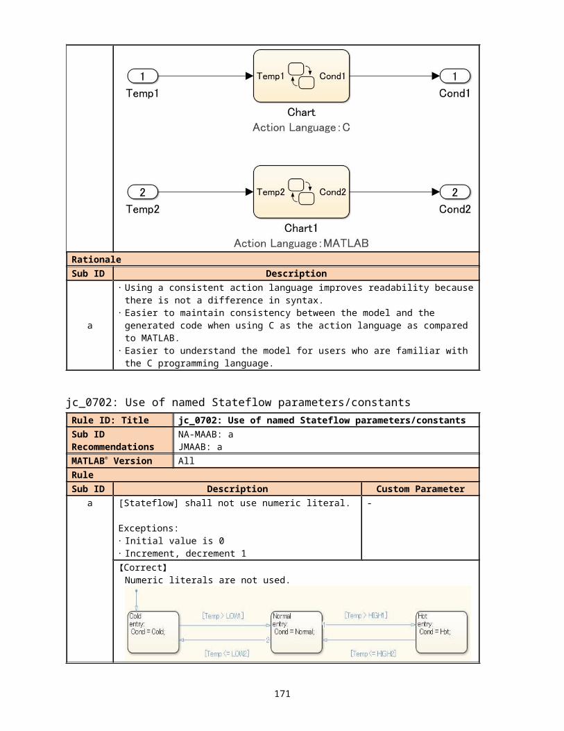
a2 When division occurs in a Stateflow block, the process shall prevent division by zero.
-
【Correct】The process is defined to prevent division by zero.
【Incorrect】The process does not prevent division by zero.
171
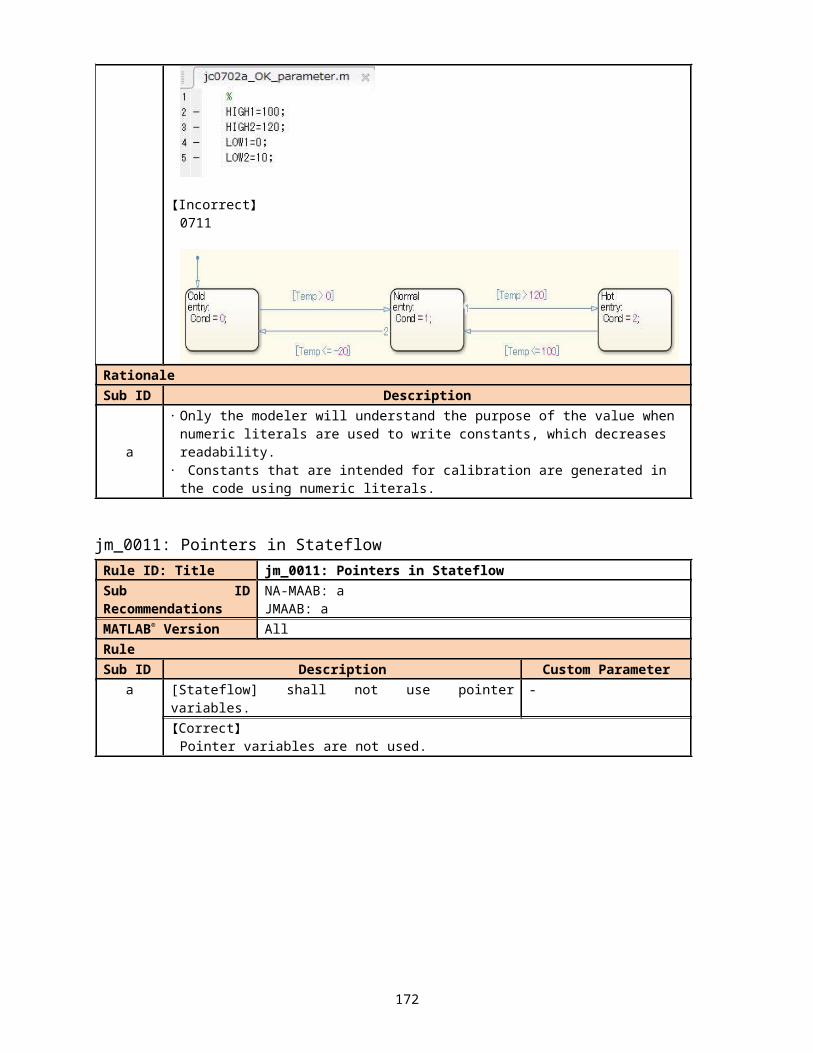
RationaleSub ID Description
a1a2 Deviation from the rule can cause unintended operation and code generation results.
db_0127: Limitation on MATLAB commands in Stateflow blocksRule ID: Title db_0127: Limitation on MATLAB commands in Stateflow blocksSub ID Recommendations
NA-MAAB: a1/a2JMAAB: a1/a2
MATLAB® Version AllRuleSub ID Description Custom Parameter
a1 MATLAB commands shall not be used in Stateflow blocks. -【Correct】
MATLAB commands are not used in Stateflow blocks.
172
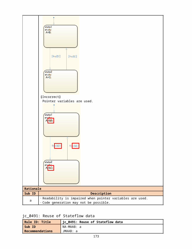
【Incorrect】A MATLAB command is used in Stateflow blocks.
a2 When a MATLAB command is used in Stateflow blocks, it shall be accessed only by using [MATLAB Function].
-
【Correct】The MATLAB command is accessed by using [MATLAB Function].
173
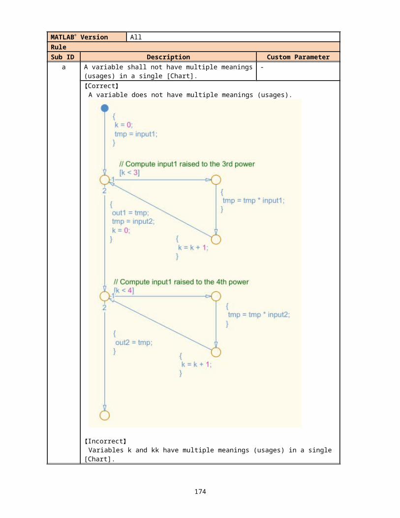
【Incorrect】 [MATLAB Function] is not used for a MATLAB command.
RationaleSub ID Description
a1 Not all MATLAB commands are supported for code generation. As a result, code may not be generated for these unsupported MATLAB commands.
a2
Not all MATLAB commands are supported for code generation. As a result, code may not be generated for these unsupported MATLAB commands.
Readability improves when C and MATLAB action languages are described separately.
jc_0481: Use of hard equality comparisons for floating point numbers in StateflowRule ID: Title jc_0481: Use of hard equality comparisons for floating point
numbers in StateflowSub ID Recommendations
NA-MAAB: aJMAAB: a
174
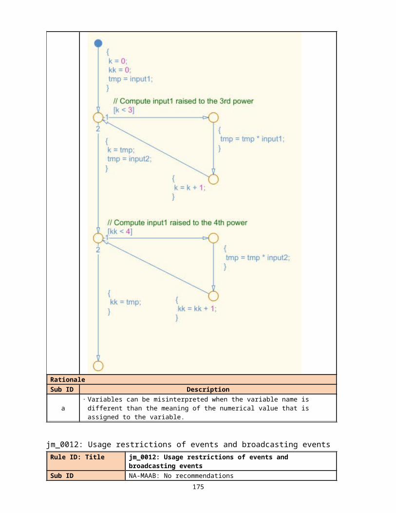
MATLAB® Version AllRuleSub ID Description Custom Parameter
a These equality comparison operators shall not be used in floating-point operands:
“==” “!=” “~=”
-
【Correct】Equality comparison operators are not used in floating-point operands.
【Incorrect】Equality comparison operator “==” is used in floating-point operands.
RationaleSub ID Description
a Due to the nature of the floating-point data type, as it contains an error, the result of the equivalence comparison operation may be false when it was expected to be true.
na_0001: Standard usage of Stateflow operatorsRule ID: Title na_0001: Standard usage of Stateflow operatorsSub ID Recommendations
NA-MAAB: No recommendationsJMAAB: a, b1/b2/b3, c
MATLAB® Version AllRuleSub ID Description Custom Parameter
a When [Chart] property {Action Language} is set to “C”, operators (“&”, “|”, “^”, “~”) shall be used only for bit operations.
-
【Correct】Operators (“&”, “|”, “^”, “~”) are used for bit operations.
175
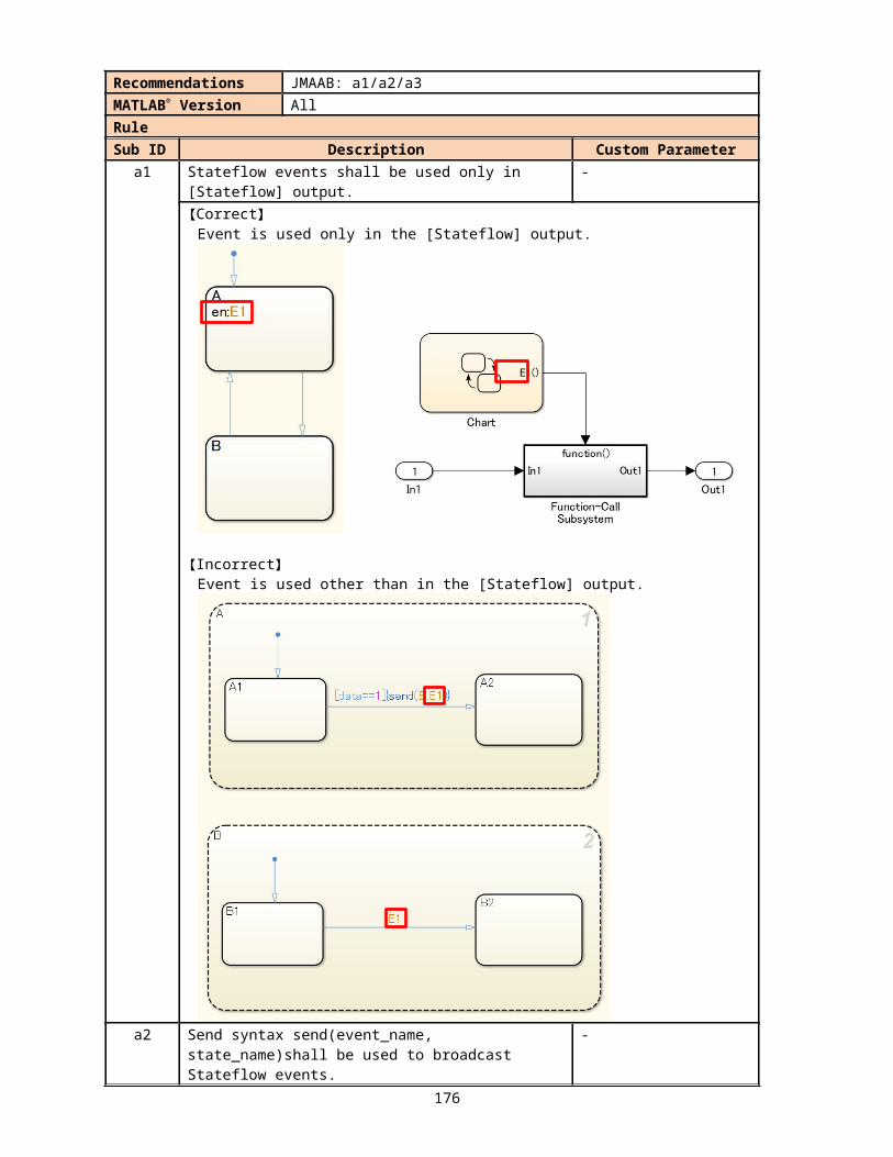
【Incorrect】Operators “&”, “|”, “^”, “~” are not used for bit operations.
b1 When [Chart] property {Action Language} is set to “C”, operator “~=” shall be used for inequality operations.
-
【Correct】Operator “~=” is used for inequality operations.
b2 When [Chart] property {Action Language} is set to “C”., operator “!=” shall be used for inequality operations.
-
【Correct】Operator “!=” is used for inequality operations.
176
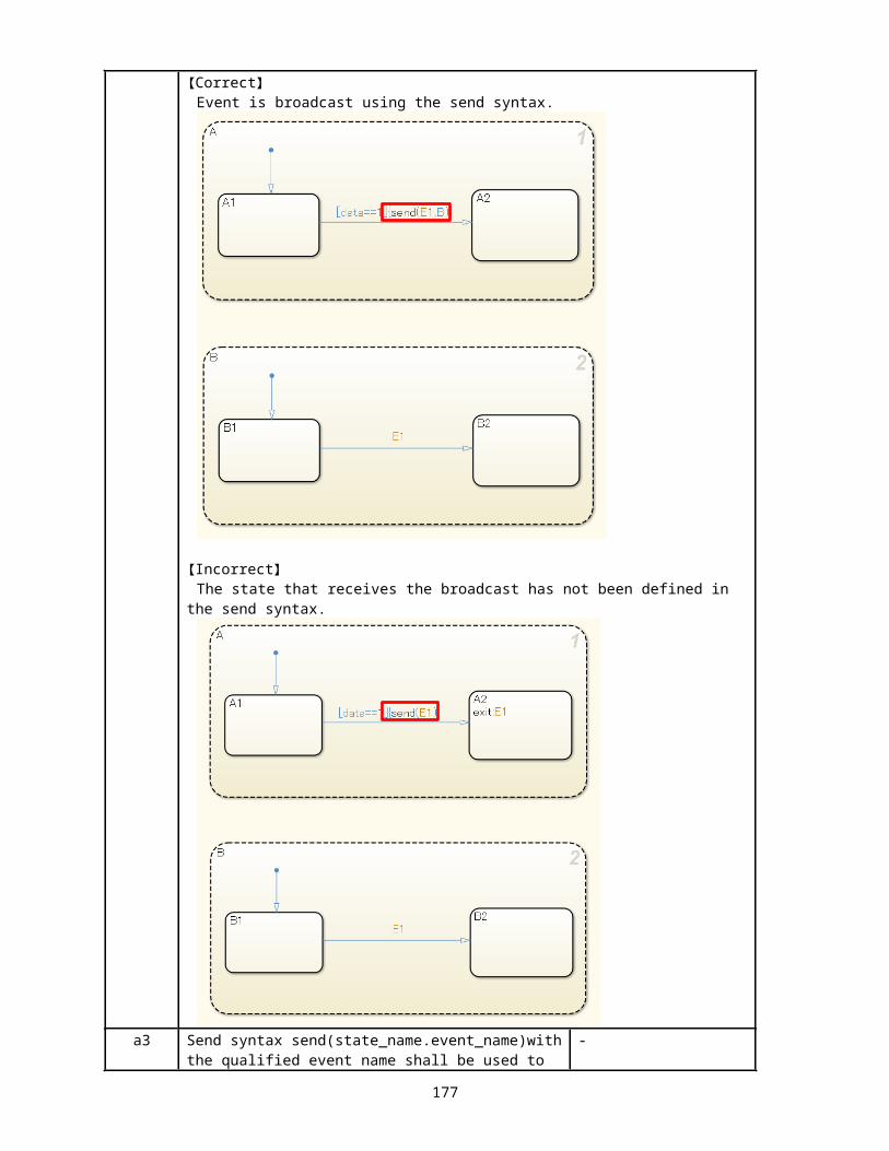
b3 When [Chart] property {Action Language} is set to “C”, operator “<>” shall be used for inequality operations.
-
【Correct】Operator “<>” is used for inequality operations.
c When [Chart] property {Action Language} is set to “C”, operation “!” shall be used for logical negation.
-
【Correct】Operator “!” is used for logical negation.
【Incorrect】An operator other than “!” should be used for logical negation.
“!” is used
177
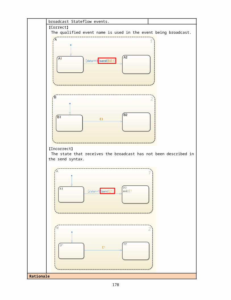
RationaleSub ID Description
a
When either of these [Chart] properties are set as follows: {Action Language} is set to “MATLAB” {Action Language} is set to “C” and {Enable C-bit operations} is selected,
“&&” and “&”, “||” and “|”, have the same calculation function. However, when “&&” and “&” or “||” and “|” are combined in the same chart, it can be difficult to determine whether these are separate calculation functions or the same calculation function.
b1b2b3 Consistent use of equality operators improves readability.
c
Consistent use of logical negation operators improves readability. When [Chart] property {C-bit operations are enabled} is selected, the function of the
“!” operator remains the same and is not affected by logic changes that result from changing the setting.
jc_0655: Prohibition of logical value comparison in StateflowRule ID: Title jc_0655: Prohibition of logical value comparison in StateflowSub ID Recommendations
NA-MAAB: No recommendationsJMAAB: a
MATLAB® Version AllRuleSub ID Description Custom Parameter
a Logical constants shall not be compared to each other. -【Correct】
Logical constants are not compared to each other.
“!” other than “!” should be used.
178
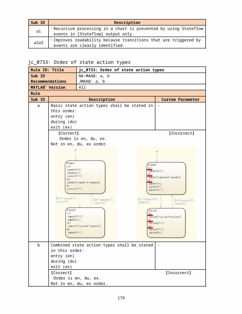
【Incorrect】Logical constants are compared to each other.
RationaleSub ID Description
a
Readability improves with consistent use of “boolean-valued signal==true(boolean type constant)” or “(boolean-valued signal)” for logical signal condition expressions.
Prevents redundancy in the model. Deviation from the rule can cause unexpected issues.
jc_0451: Use of unary minus on unsigned integersRule ID: Title jc_0451: Use of unary minus on unsigned integersSub ID Recommendations
NA-MAAB: aJMAAB: a
MATLAB® Version AllRuleSub ID Description Custom Parameter
a Unary minus shall not be used on unsigned integers. -
179
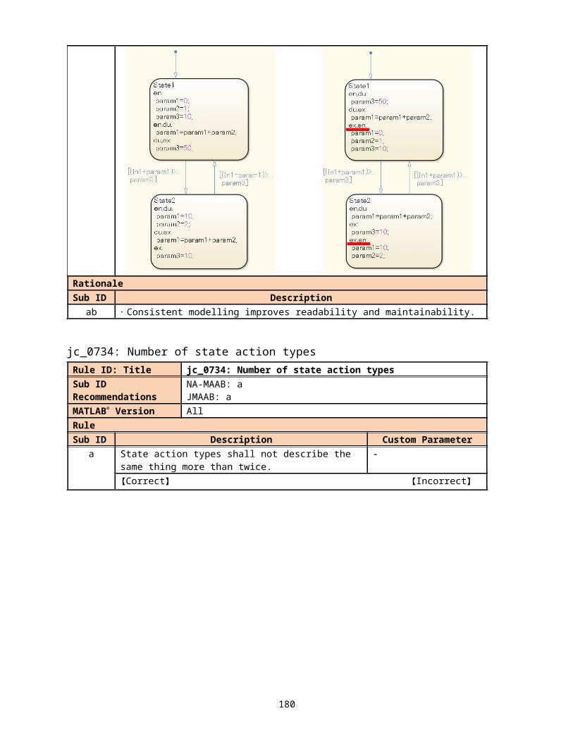
【Correct】
【Incorrect】Negative values cannot be input into 16-bit environments.(Negative values can be input into 32-bit environments)
RationaleSub ID Description
a As the results are depend on the execution environment, unintended results can occur.
jc_0802: Prohibited use of implicit type casting in StateflowRule ID: Title jc_0802: Prohibited use of implicit type casting in StateflowSub ID Recommendations
NA-MAAB: aJMAAB: a
MATLAB® Version AllRuleSub ID Description Custom Parameter
a All operations, including substitution, comparison, arithmetic, etc., shall be performed between variables of the same data type. The data type of the actual arguments and the formal arguments in a function call shall be the same.
-
【Correct】 Variables use the same data type for calculations.
Example: Comparison operation
Example: Arithmetic operations and assignment operations (compound expressions)
180
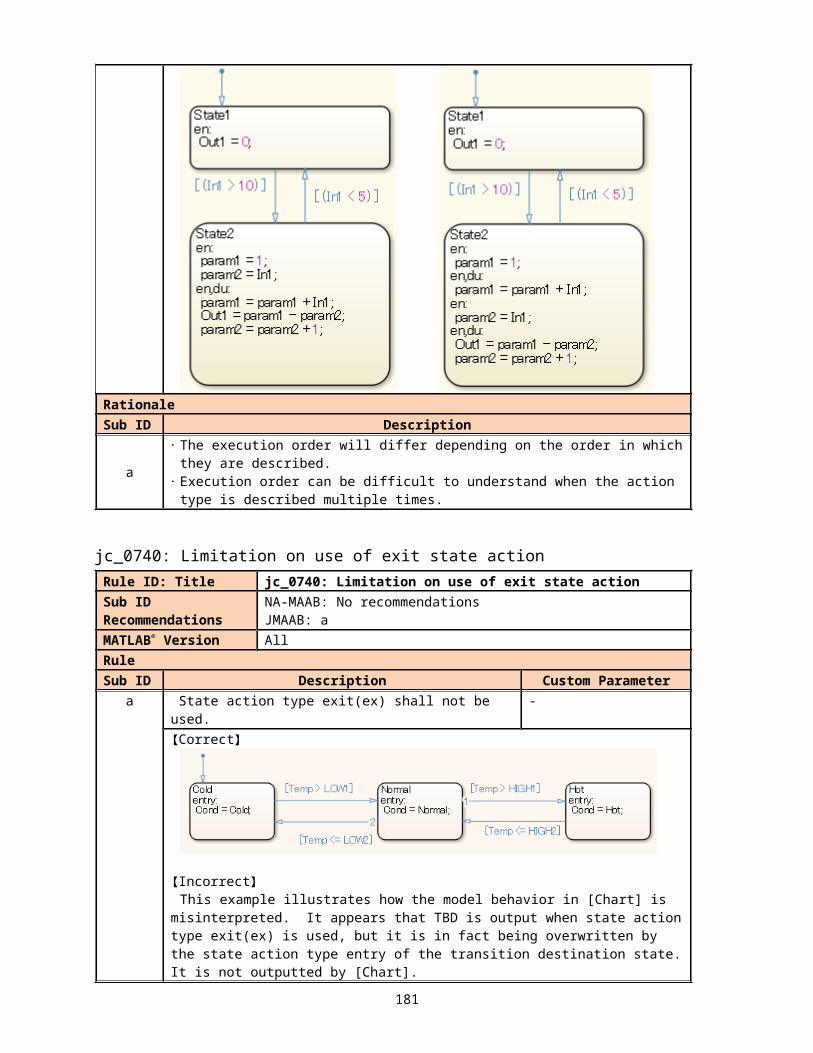
Variables have different data types but are explicitly typecast before calculation.Example: Comparison operation
Example: Arithmetic operations and assignment operations (compound expressions)
The data type of actual arguments and formal arguments in the function call are the same.
【Incorrect】 Variables use different data types for calculations.
Example: Comparison operation
Example: Arithmetic operations and assignment operations (compound expressions)
Calculations are performed between unsigned integer type variables and signed integers.
181
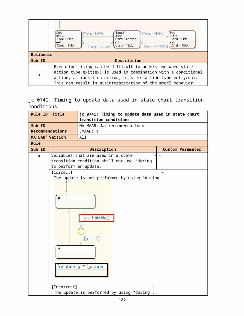
The data type of actual arguments and formal arguments in the function call are different.
RationaleSub ID Description
a Implicit data type conversion can produce unexpected results.
jc_0803: Passing values to library functionsRule ID: Title jc_0803: Passing values to library functionsSub ID Recommendations NA-MAAB: 1/a2, b1/b2, c1/c2, d1/d2
JMAAB: 1/a2, b1/b2, c1/c2, d1/d2MATLAB® Version AllRuleSub ID Description Custom Parameter
a1 A minimum value for the signed integer type shall not be provided when using the abs library function.
-
【Correct】
【Incorrect】
a2 The abs library function shall not be used. -b1 A negative number shall not be entered when using the
sqrt library function. -
【Correct】
182
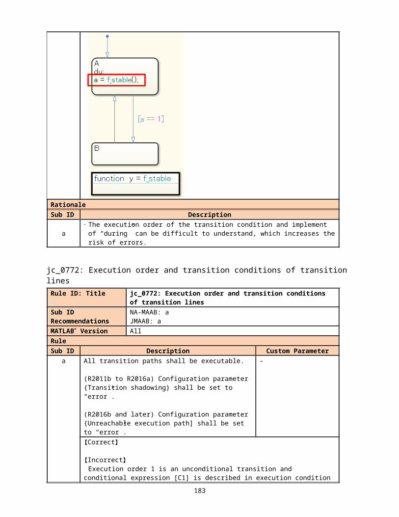
【Incorrect】
b2 The sqrt library function shall not be used. -c1 A negative number shall not be entered when using the
log and log10 library functions. -
【Correct】
【Incorrect】
c2 The log or log10 library functions shall not be used. -d1 Zero shall not be entered for the second argument when
using the fmod library function. -
【Correct】
【Incorrect】
183
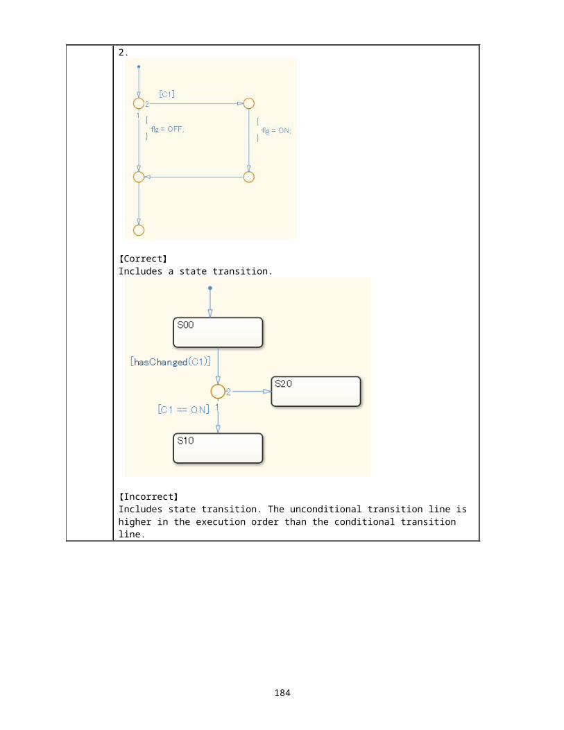
d2 The fmod library function shall not be used. -RationaleSub ID Description
a1b1c1d1 The behavior of a library function when an invalid value has been passed is dependent on the processing system and may result in unintended behavior.
a2b2c2d2
To avoid duplicate modelling of the same guard process in Simulink and Stateflow, use Simulink to perform arithmetic operations.
4.4. Label description
jc_0732: Distinction between state names, data names, and event namesRule ID: Title jc_0732: Distinction between state names, data names, and event
namesSub ID Recommendations
NA-MAAB: aJMAAB: a
MATLAB® Version AllRuleSub ID Description Custom Parameter
a An identical name shall not be used for state, data (inputs and outputs, local data, constants, parameters, data store memory), or event names in a single [Chart].
-
【Correct】Names are not duplicated.
OnB
OffB
[b == B2][b == B1]
ModelB
OffA
OnA
[a == A2][a == A1]
ModelA
[condition == C2]
[condition == C1]
【Incorrect】Names are duplicated.
184
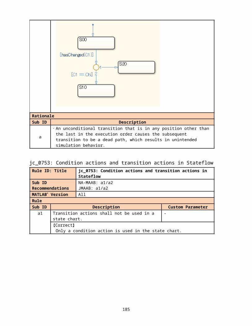
RationaleSub ID Description
a Using unique names prevent misunderstanding.
jc_0730: Unique state name in Stateflow blocksRule ID: Title jc_0730: Unique state name in Stateflow blocksSub ID Recommendations
NA-MAAB: aJMAAB: a
MATLAB® Version AllRuleSub ID Description Custom Parameter
a State names in [Chart] shall be unique.The content of linked atomic sub-charts can be treated as another [Chart].
-
RationaleSub ID Description
a Readability is impaired. Deviation from the rule can cause unintended code behavior.
jc_0731: State name formatRule ID: Title jc_0731: State name formatSub ID Recommendations
NA-MAAB: aJMAAB: a
MATLAB® Version AllRuleSub ID Description Custom Parameter
a The state name shall be followed by a new line that does not include a slash (/).
-
【Correct】
185
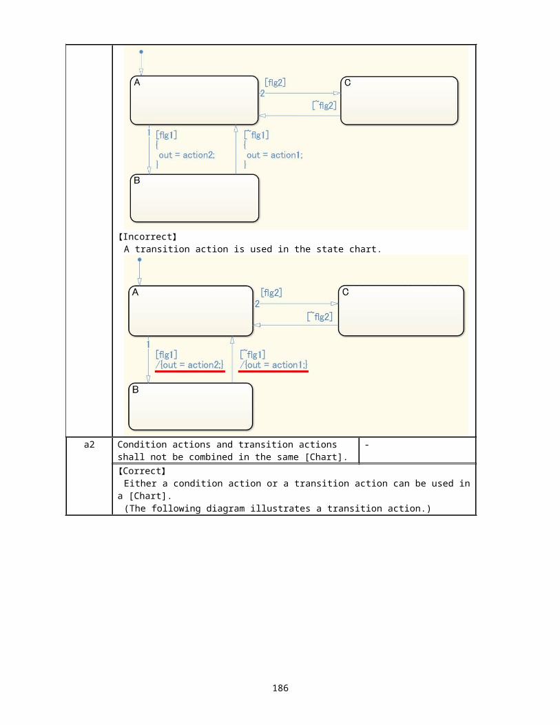
【Incorrect】
RationaleSub ID Description
a Readability improves when state names are described consistently.
jc_0501: Line breaks in state labelsRule ID: Title jc_0501: Line breaks in state labelsSub ID Recommendations
NA-MAAB: aJMAAB: a
MATLAB® Version AllRuleSub ID Description Custom Parameter
a A state action statement shall not be written on the same line as a state action type.
-
【Correct】
【Incorrect】
RationaleSub ID Description
a Readability is impaired.
186
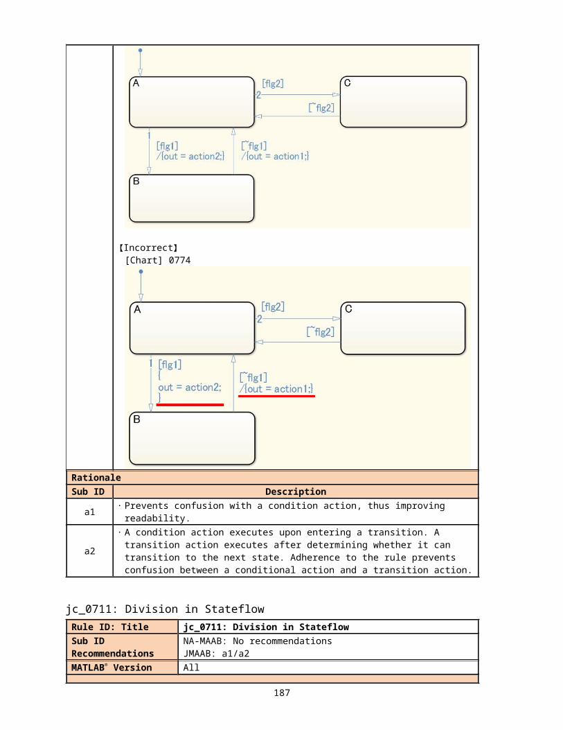
jc_0736: Uniform indentations in Stateflow blocksRule ID: Title jc_0736: Uniform indentations in Stateflow blocksSub ID Recommendations
NA-MAAB: No recommendationsJMAAB: a, b, c
MATLAB® Version AllRuleSub ID Description Custom Parameter
a State action types shall not have blank spaces at the start of a line.Executable statements shall have one single-byte space at the start of the line.
Number of single-byte spaces
【Correct】Executable statements use one single-byte space at the start of the line.
【Incorrect】Executable statements do not have a single-byte space at the start of the line.
b A blank space shall not be entered before the following: “[“ of a transition condition “{“ of a condition action “/” of a transition action
-
【Correct】A blank space is not entered before the “[“ and “{“ of the transition label condition,
condition action, and transition action.
187
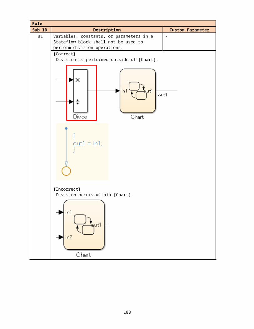
【Incorrect】A blank space is entered before the “[“ and “{“ of the transition label condition,
condition action, and transition action.
c At least one single-byte space shall be entered after the “/” of a transition action.
Number of single-byte spaces
【Correct】Single-byte spaces are entered after the “/” of the transition action.
【Incorrect】There are no single-byte spaces after the “/” of the transition action.
Rationale
188
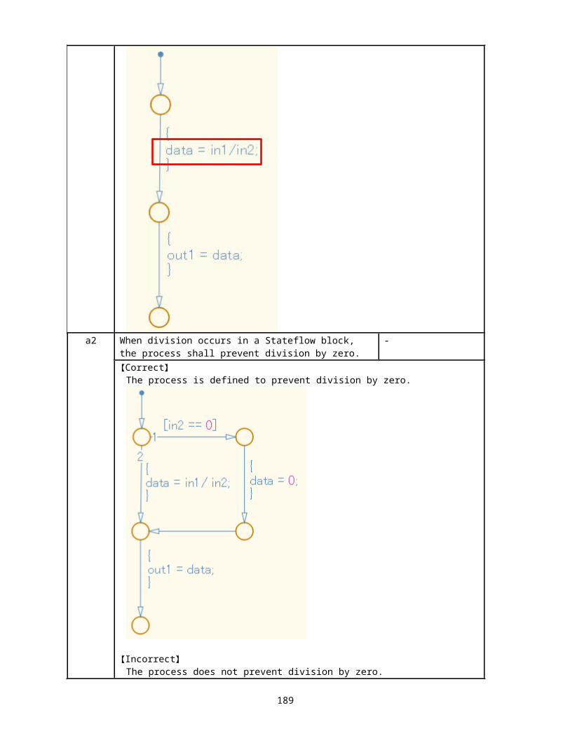
Sub ID Description
a Using uniform indents before the executable statement clarifies the link between
the state action type of a state label and the execution statement, improving readability.
b Using uniform indents for transition conditions, condition actions, and transition actions improves readability.
c Consistent use of blank spaces improves readability.
jc_0739: Describing text inside statesRule ID: Title jc_0739: Describing text inside statesSub ID Recommendations
NA-MAAB: aJMAAB: a
MATLAB® Version AllRuleSub ID Description Custom Parameter
a Text inside a state shall not extend beyond the boundaries of the state.
-
【Incorrect】
189
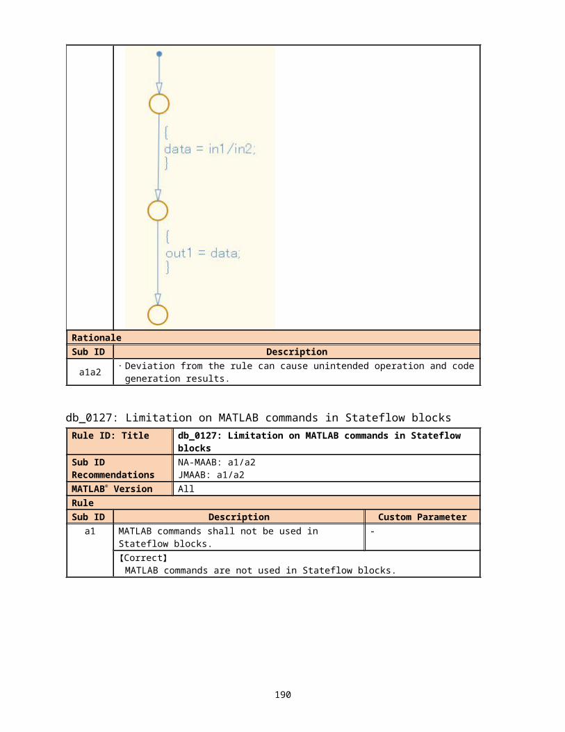
RationaleSub ID Description
a When the text inside a state extends beyond its boundaries, it can be difficult to determine which state the text belongs.
jc_0770: Position of transition labelRule ID: Title jc_0770: Position of transition labelSub ID Recommendations
NA-MAAB: No recommendationsJMAAB: a1/a2
MATLAB® Version AllRuleSub ID Description Custom Parameter
a1 Transition labels are positioned at the transition line point of origin.
-
190
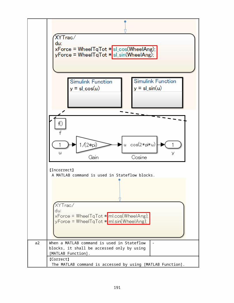
【Correct】Transition labels are positioned at the point of origin.
【Incorrect】The positioning of transition labels is inconsistent and do not correspond to the
transition line.
a2 Transition labels are positioned near the center of the transition line.
-
【Correct】Transition labels are positioned near the center of the transition line.
191
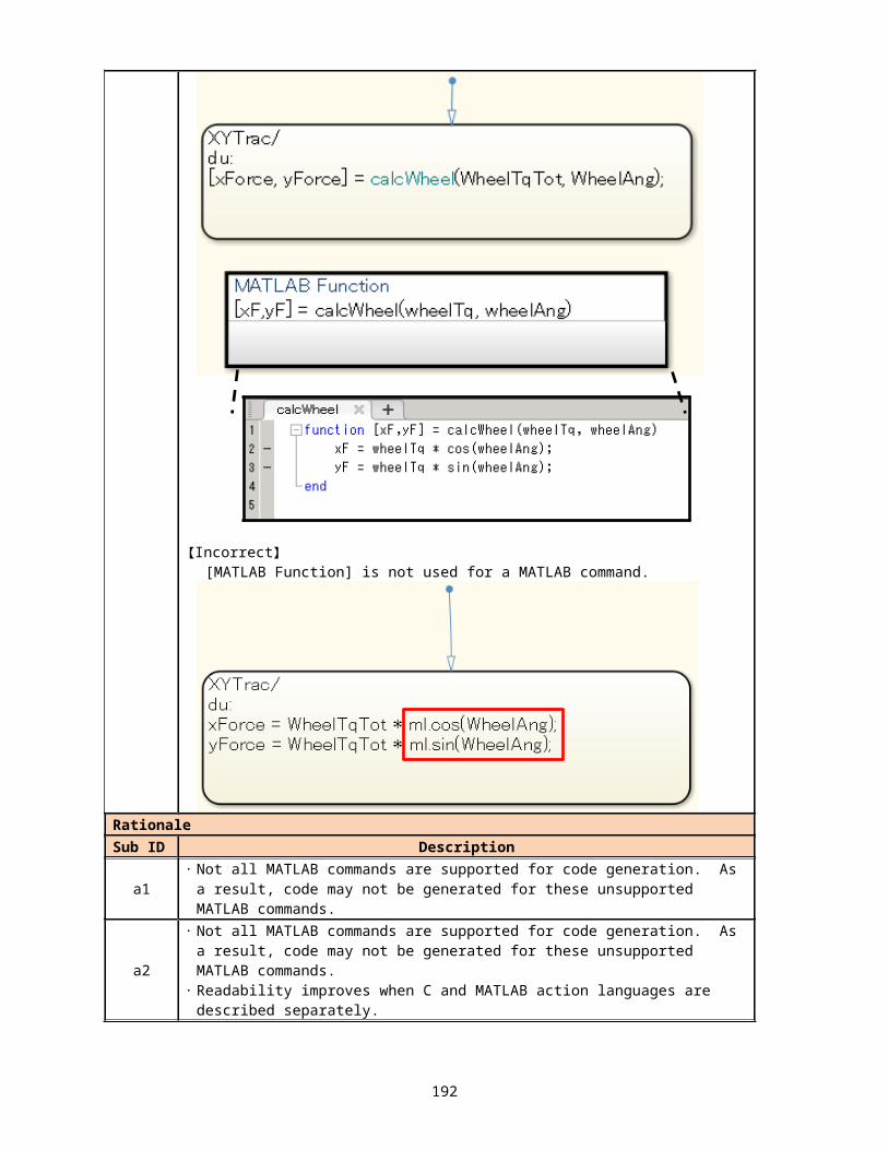
【Incorrect】The positioning of transition labels is inconsistent and do not correspond to the
transition line.
RationaleSub ID Description
a1a2 Consistent positioning of transition labels makes the correspondence between label and line easier to understand.
jc_0771: Comment position in transition labelsRule ID: Title jc_0771: Comment position in transition labelsSub ID Recommendations
NA-MAAB: a1/a2JMAAB: a1/a2
MATLAB® Version AllRuleSub ID Description Custom Parameter
a1 Comments in transition labels shall be positioned above transition conditions, condition actions, transition actions, and Stateflow events.
-
【Correct】The position of the comments in the transition labels is uniform.
192
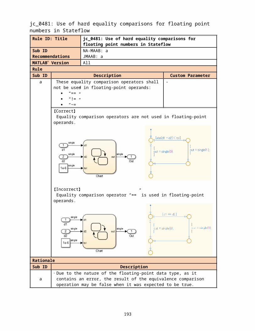
【Incorrect】The position of the comments in the transition labels is inconsistent.
a2 Comments in transition labels shall be positioned below transition conditions, condition actions, transition actions, and Stateflow events.
-
【Correct】The position of the comments in the transition labels is uniform.
193
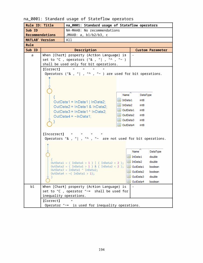
【Incorrect】The position of the comments in the transition labels is inconsistent.
RationaleSub ID Description
a1a2 Uniform positioning of comments in transition labels clarifies to which transition condition, condition action, transition action, or Stateflow event the label corresponds.
jc_0752: Condition action in transition labelRule ID: Title jc_0752: Condition action in transition labelSub ID NA-MAAB: No recommendations
194
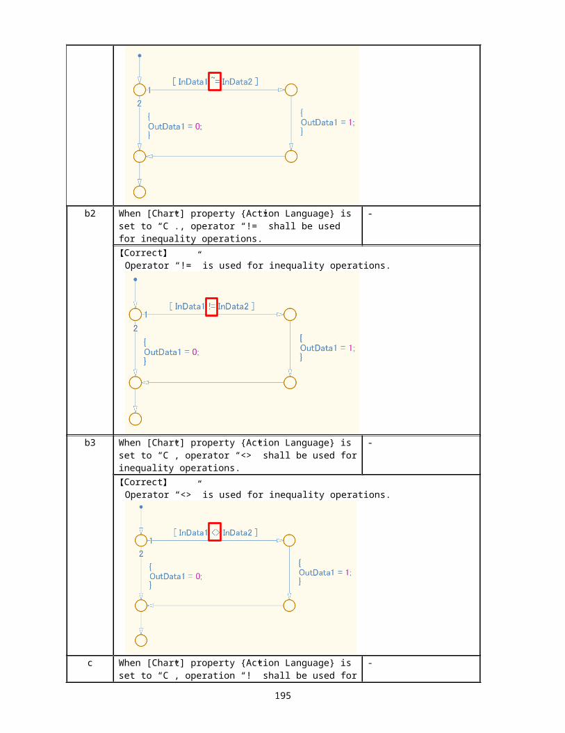
Recommendations JMAAB: aMATLAB® Version AllRuleSub ID Description Custom Parameter
a Parentheses in condition actions shall use only curly brackets on a single line.(A new line shall start before and after curly brackets.)
-
【Correct】Note: The example is for a flow chart, but the rule also applies to state transitions.
Incorrect
RationaleSub ID Description
a Clarifying condition actions improves readability.
jc_0774: Comments for through transitionRule ID: Title jc_0774: Comments for through transitionSub ID Recommendations
NA-MAAB: aJMAAB: a
MATLAB® Version AllRuleSub ID Description Custom Parameter
a When there is no processing in an unconditional transition, a clarifying comment shall be written on the transition label.
-
【Correct】A clarifying comment is provided.
195
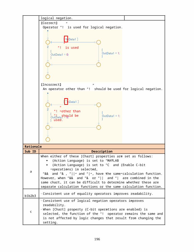
【Incorrect】A clarifying comment is not provided on the condition path, so it is difficult to
determine whether the lack of action is intentional.
RationaleSub ID Description
a Clarifies that the processing is deliberately excluded. The comment that is added to a transition label is also included in the generated
code.
4.5. Miscellaneous
jc_0511: Return values from a graphical functionRule ID: Title jc_0511: Return values from a graphical functionSub ID Recommendations
NA-MAAB: No recommendationsJMAAB: a
196
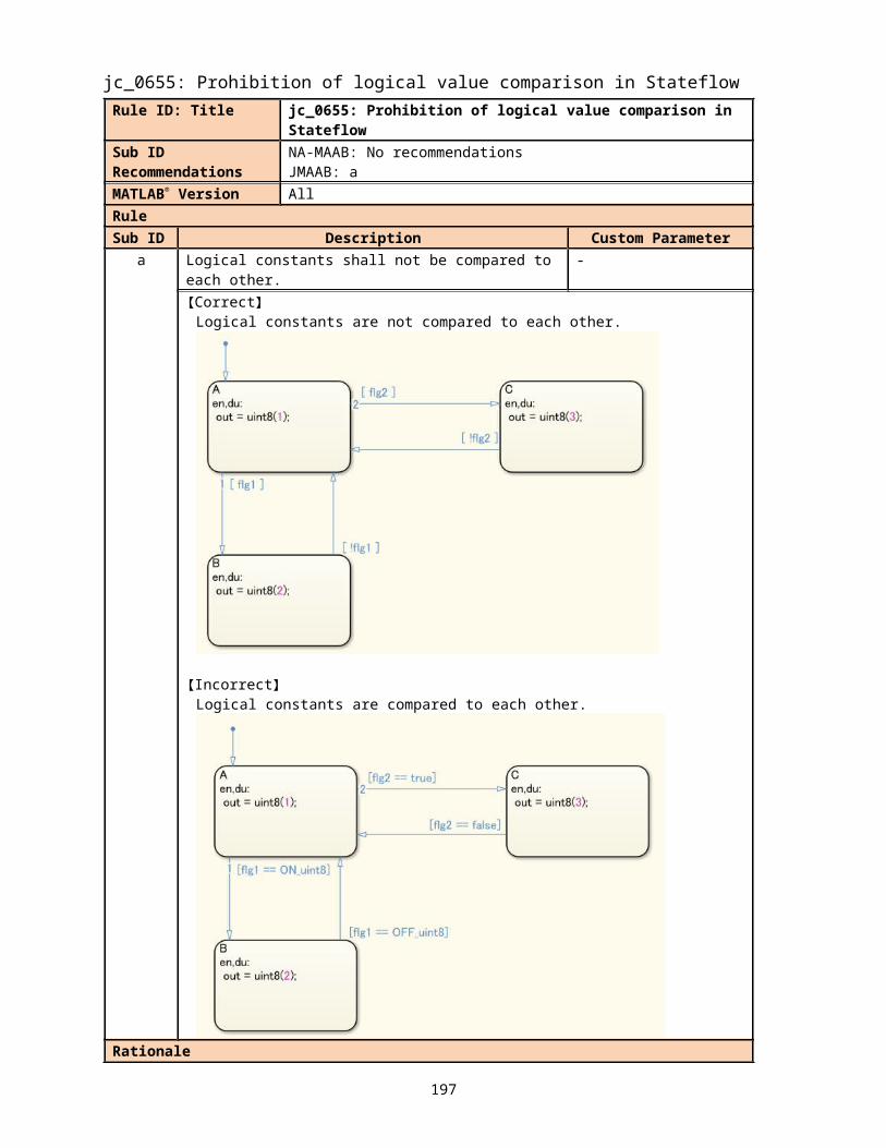
MATLAB® Version AllRuleSub ID Description Custom Parameter
a The return value for graphical functions shall be set in one place only.
-
【Correct】
【Incorrect】
RationaleSub ID Description
a Modifications to the output name is limited to prevent the changes from being missed or overlooked.
jc_0804: Prohibited use of recursive calls with graphical functionsRule ID: Title jc_0804: Prohibited use of recursive calls with graphical functionsSub ID Recommendations
NA-MAAB: aJMAAB: a
MATLAB® Version AllRuleSub ID Description Custom Parameter
a Calls from a graphical function to itself and calls between -
197
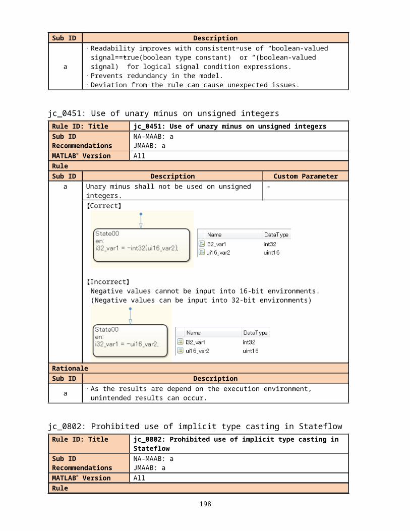
graphical functions shall be prohibited.【Correct】
Processing is performed within the graphical function.
【Incorrect】The graphical function is calling itself.
Graphical functions are calling each other.
RationaleSub ID Description
a Readability decreases. Deviation from the rule can cause unintended overflows and infinite loops.
na_0042: Usage of Simulink functionsRule ID: Title na_0042: Usage of Simulink functionsSub ID Recommendations
NA-MAAB: aJMAAB: a
MATLAB® Version AllRule
198
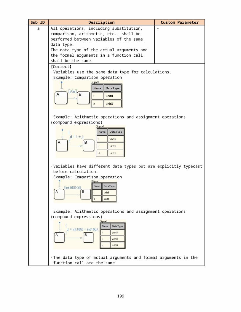
Sub ID Description Custom Parametera When using [Simulink Function] in [Chart], one or more of
the following conditions shall be met. Input/output variables shall use only local [Chart] data
in the [Simulink Function]. Input/output variables shall use only local [Chart] data
and input data in the [Simulink Function]. [Simulink Function] shall be called from multiple
places in [Chart]. [Simulink Function] shall not be called at every time
step.
-
【Correct】[Simulink Function] lookup1D is not called from every time step and, therefore, can be
used.
【Incorrect】[Simulink Function] lookup1D is called from every time step and, therefore, cannot be
used. (out is the Stateflow output data)
RationaleSub ID Description
a To improve model readability, the use of [Simulink Functions] should be used with caution in charts.
na_0039: Limitation on Simulink functions in Chart blocksRule ID: Title na_0039: Limitation on Simulink functions in Chart blocksSub ID Recommendations
NA-MAAB: aJMAAB: a
MATLAB® Version AllRuleSub ID Description Custom Parameter
199
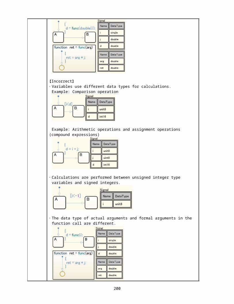
a Stateflow blocks shall not be used in [Simulink Functions] that are included in Stateflow [Chart].
-
【Incorrect】
RationaleSub ID Description
a Readability decreases and can result in design errors.
200
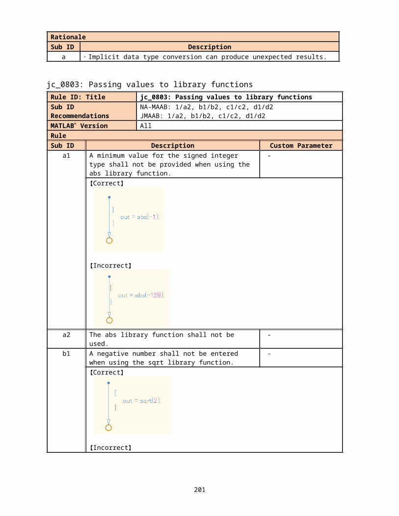
5. MATLAB
5.1. MATLAB Appearance
na_0018: Number of nested if/else and case statementsRule ID: Title na_0018: Number of nested if/else and case statementsSub ID Recommendations
NA-MAAB: aJMAAB: Not supported
MATLAB® Version AllRuleSub ID Description Custom Parameter
a The number of levels of nested if /else and case statements shall be limited, typically to three levels.
Maximum nested levels
RationaleSub ID Description
a Improves readability Code generation may not be possible.
na_0025: MATLAB Function headersRule ID: Title na_0025: MATLAB Function headersSub ID Recommendations NA-MAAB: a
JMAAB: Not supportedMATLAB® Version AllRuleSub ID Description Custom Parameter
a [MATLAB Functions] shall have a descriptive header.
Information in the header can include, but is not limited to: Function name Description of function Assumptions and limitations Description of changes from previous versions Lists of inputs and outputs
Example:
-
201
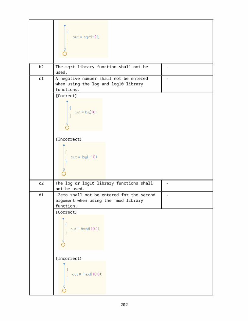
RationaleSub ID Description
a Improves readability, model simulation, testability, and workflow Code generation may not be possible.
5.2. MATLAB Data and Operations
na_0024: Shared data in MATLAB functionsRule ID: Title na_0024: Shared data in MATLAB functionsSub ID Recommendations
NA-MAAB: aJMAAB: a
MATLAB® Version AllRuleSub ID Description Custom Parameter
a Signal lines shall be used to connect data that is shared between MATLAB functions.
-
【Correct】
202
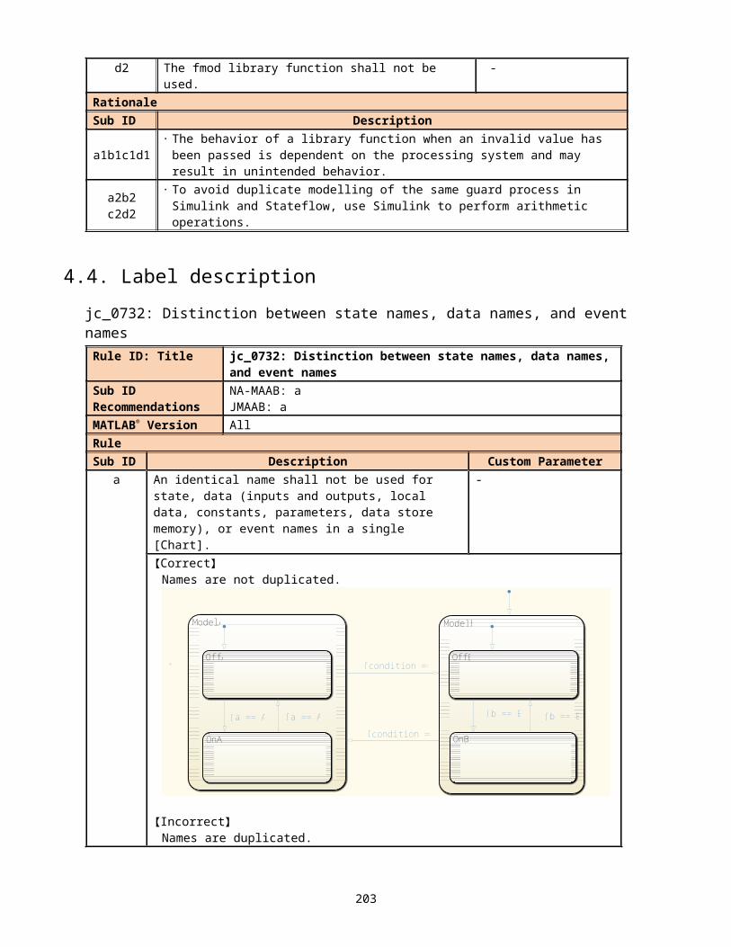
【Incorrect】This type of pattern cannot be used when the rule is applied.
function ErrorFlag = EngineFaultEvaluation(EngineData,ErrorFlag_In)%#codegen RPM_HIGH = 10000; RPM_LOW = 10; HIGHRPMFAULT = 2^1; LOWRPMFAULT = 2^2; ErrorFlag = ErrorFlag_In; if EngineData > RPM_HIGH ErrorFlag = bitor(ErrorFlag,HIGHRPMFAULT); end if EngineData < RPM_LOW ErrorFlag = bitor(ErrorFlag,LOWRPMFAULT); endendfunction ErrorFlag = WheelFaultEvaluation(WheelData,ErrorFlag_In)%#codegen SLIP_HIGH = 1000; WHEELSLIP = 2^3; ErrorFlag = ErrorFlag_In; if WheelData > SLIP_HIGH ErrorFlag = bitor(ErrorFlag,WHEELSLIP); end
function EngineFaultEvaluation(EngineData)%#codegen global ErrorFlag_DataStore RPM_HIGH = 10000; RPM_LOW = 10; HIGHRPMFAULT = 2^1; LOWRPMFAULT = 2^2; if EngineData > RPM_HIGH ErrorFlag_DataStore = bitor(ErrorFlag_DataStore,HIGHRPMFAULT); end if EngineData < RPM_LOW ErrorFlag_DataStore = bitor(ErrorFlag_DataStore,LOWRPMFAULT); end
203
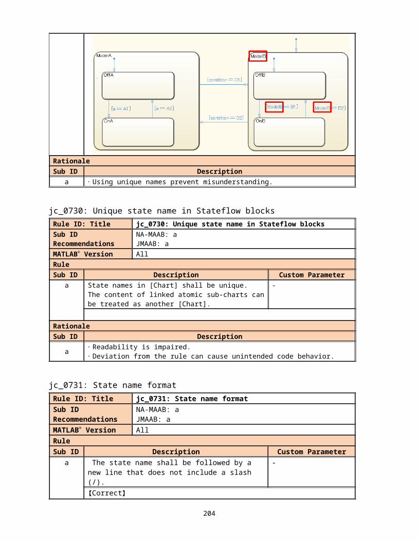
RationaleSub ID Description
a When a data store is used, the readability of the data flow decreases and can lead to errors in the update reference timing.
na_0031: Definition of default enumerated valueRule ID: Title na_0031: Definition of default enumerated valueSub ID Recommendations
NA-MAAB: aJMAAB: a
MATLAB® Version AllRuleSub ID Description Custom Parameter
a Method getDefaultValue shall be used to explicitly define the default value of an enumeration.
-
【Correct】
【Incorrect】
RationaleSub ID Description
a When an enumerated type does not have a clearly defined a default value, the first
enumeration string that is described will be defined as the default, which may not be as intended.
function WheelFaultEvaluation(WheelData)%#codegen global ErrorFlag_DataStore SLIP_HIGH = 1000; WHEELSLIP = 2^3; if WheelData > SLIP_HIGH ErrorFlag_DataStore = bitor(ErrorFlag_DataStore,WHEELSLIP); end
204
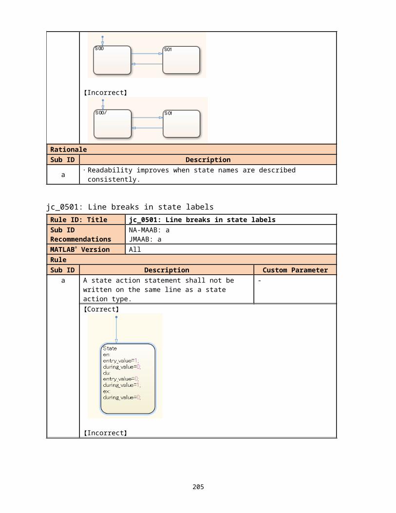
na_0034: MATLAB Function block input/output settingsRule ID: Title na_0034: MATLAB Function block input/output settingsSub ID Recommendations
NA-MAAB: aJMAAB: a
MATLAB® Version AllRuleSub ID Description Custom Parameter
a The data type in the model explorer shall be defined for all input and output to [MATLAB Function].
-
RationaleSub ID Description
a Defining the data type for all input and output to [MATLAB Function] helps prevent simulation errors and unexpected behavior.
5.3. MATLAB Usage
na_0016: Source lines of MATALAB FunctionsRule ID: Title na_0016: Source lines of MATALAB FunctionsSub ID Recommendations
NA-MAAB: aJMAAB: Not supported
MATLAB® Version AllRuleSub ID Description Custom Parameter
a The length of MATLAB functions shall be limited. This restriction applies to MATLAB Functions that reside in the Simulink block diagram and external MATLAB files with a .m extension.
The recommended limit is 60 lines of code. Subfunctions may use an additional 60 lines of code.
Maximum effective lines of code per function
RationaleSub ID Description
a Improves readability and workflow Code generation may not be possible.
na_0017: Number of called function levelsRule ID: Title na_0017: Number of called function levelsSub ID Recommendations
NA-MAAB: aJMAAB: Not supported
MATLAB® Version AllRuleSub ID Description Custom Parameter
a The number of sub-function levels shall be limited, typically to three levels.
MATLAB function blocks that resides at the Simulink block diagram level counts as the first level, unless it is simply a wrapper for an external MATLAB file with a .m extension.
This includes functions that are defined within the MATLAB block and those in separate .m files.
Standard utility functions, such as built in functions like
Maximum function call levels
205
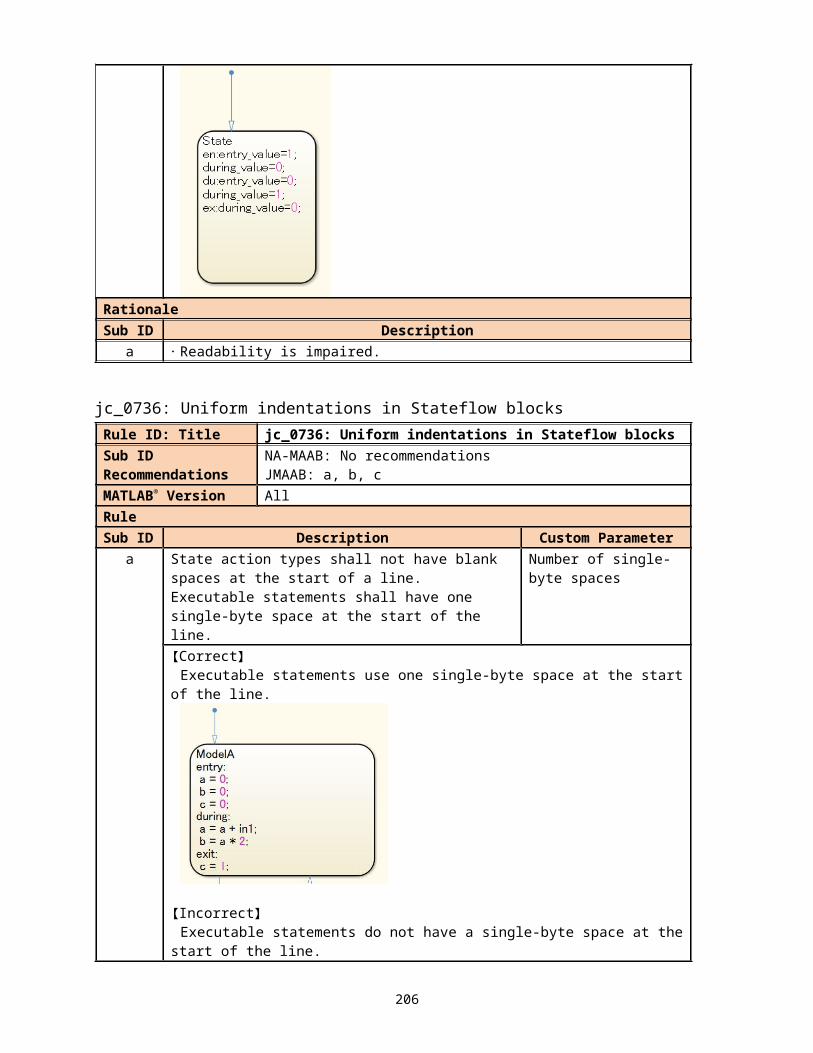
sqrt or log, are not included in the number of levels. Likewise, commonly used custom utility functions can be excluded from the number of levels.
RationaleSub ID Description
a Improves readability and testability
na_0021: Strings in MATLAB functionsRule ID: Title na_0021: Strings in MATLAB functionsSub ID Recommendations
NA-MAAB: aJMAAB: a
MATLAB® Version AllRuleSub ID Description Custom Parameter
a Assignment statements for strings shall not be used in MATLAB functions.
-
【Incorrect】An assignment statement for strings is being used in the MATLAB function.
RationaleSub ID Description
a
MATLAB functions store strings as character arrays.As a result, storing strings of different lengths in the same variable does not support dynamic memory allocation, which prevents the strings from being stored.(Consider using enumerated types when a string is used in [Switch Case])
na_0022: Recommended patters for Switch/Case statementsRule ID: Title na_0022: Recommended patters for Switch/Case statements
206
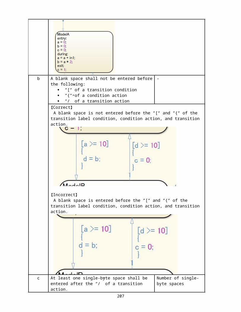
Sub ID Recommendations NA-MAAB: aJMAAB: Not supported
MATLAB® Version AllRuleSub ID
Description Custom Parameter
a Switch / Case statements shall use constant values for the “Case” arguments. Input variables shall not be used in the “Case” arguments.
【Correct】
【Incorrect】
-
RationaleSub ID
Description
a Improves model simulation and testability. Code generation may not be possible.
jc_0801: Prohibited use of the /* and */ comment symbolsRule ID: Title jc_0801: Prohibited use of the /* and */ comment symbolsSub ID Recommendations
NA-MAAB: aJMAAB: a
MATLAB® Version AllRuleSub ID Description Custom Parameter
a As comment symbols /* and */ are automatically assigned -
207
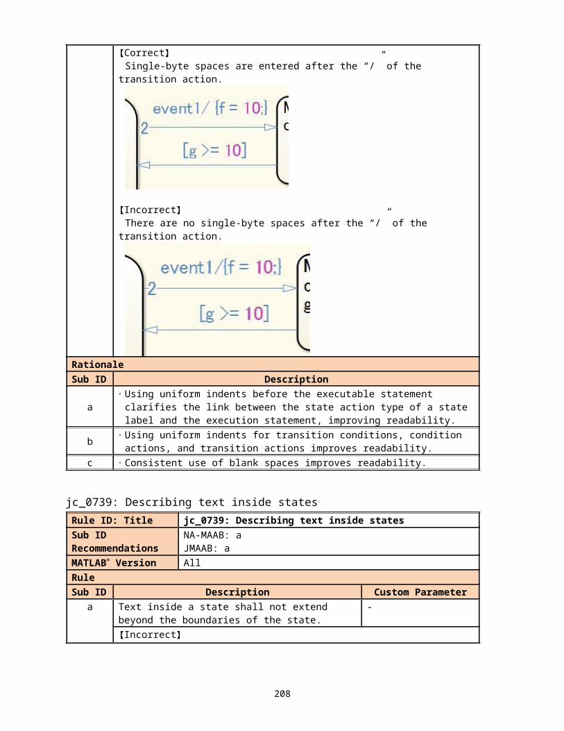
in the generated code, the symbol shall not be used in: cgt file mpt Signal description mpt parameter description
【Incorrect】In a cgt file.
【Incorrect】mpt Signal description (the same also applies to mpt.Parameter).
0011RationaleSub ID Description
208
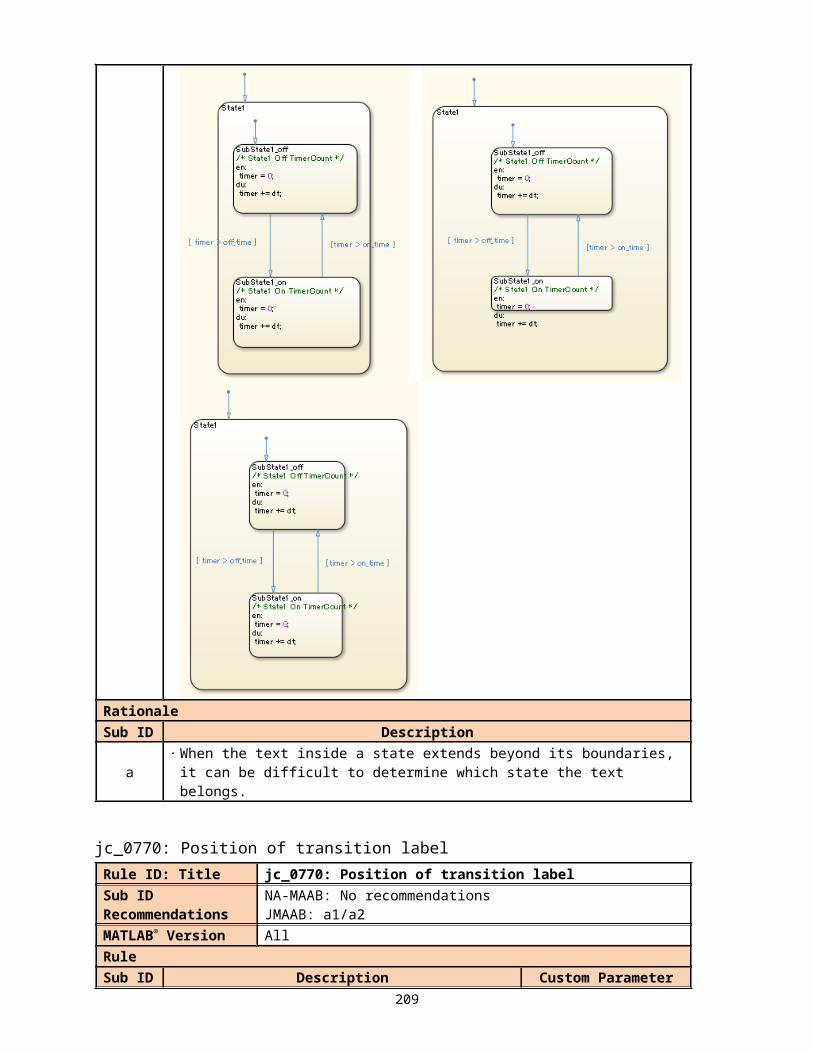
a Since comment symbols /* and */ are automatically assigned in the generated code, comments can be unintentionally nested and behave differently than expected.
209
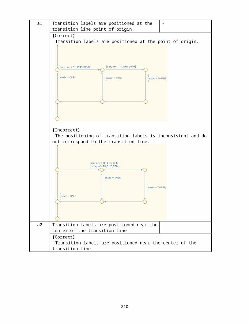
6. GlossaryThis section provides clarification of terms that are used in the guidelines.
Terms Definition
Parameters When modifications have not been made, this term refers to constants that are defined in the base workspace/model workspace.
Built-in MATLAB functions
MATLAB functions and scripts.
Reserved MATLAB words
Block
All blocks (Type=Block), including: Subsystems Models charts (unless otherwise stated).
Standard Simulink library blocks are divided into two categories: Basic blocks Structural subsystems.
Basic Blocks
Built-in blocks in the standard Simulink library.Blocks with undefined internal processing, such as subsystems, are not considered basic blocks.
Basic blocks can include:
1Out1 Terminator
~= 0
Switch
Scope
Saturation
<=
RelationalOperator
Product
AND
LogicalOperator
Ground
1
Gain
K Tsz-1
Discrete-TimeIntegrator
1
Constant
1In1
Z-1
DelaySaturation1z1
Unit Delay
Structural subsystem
[Subsystems], [models], [charts], and [MATLAB functions] are frameworks for defining the structure, blocks with user-defined internal processing.
Subsystem
A subsystem that can be internally modeled by using Simulink basic projection.Even if {BlockType} is "subsystem", [Chart], [MATLAB Function], etc. blocks that describe the inside (other than Simulink basic projection) are not included.[Model] is not included.
Conditional subsystem
A subsystem with conditional input ports.
Atomic subsystem
A {BlockType} that is a “subsystem” and executes the structural subsystem as a single unit.Conditional subsystems, [Chart], and [MATLAB Function] are considered atomic subsystems.
Port label name
The input/output port labels of a structural subsystem.The names of [Inport] and [Outport] blocks are placed in a subsystem by default. Names of Stateflow input/output data are displayed by default. The display option can be changed when masking a subsystem.
210
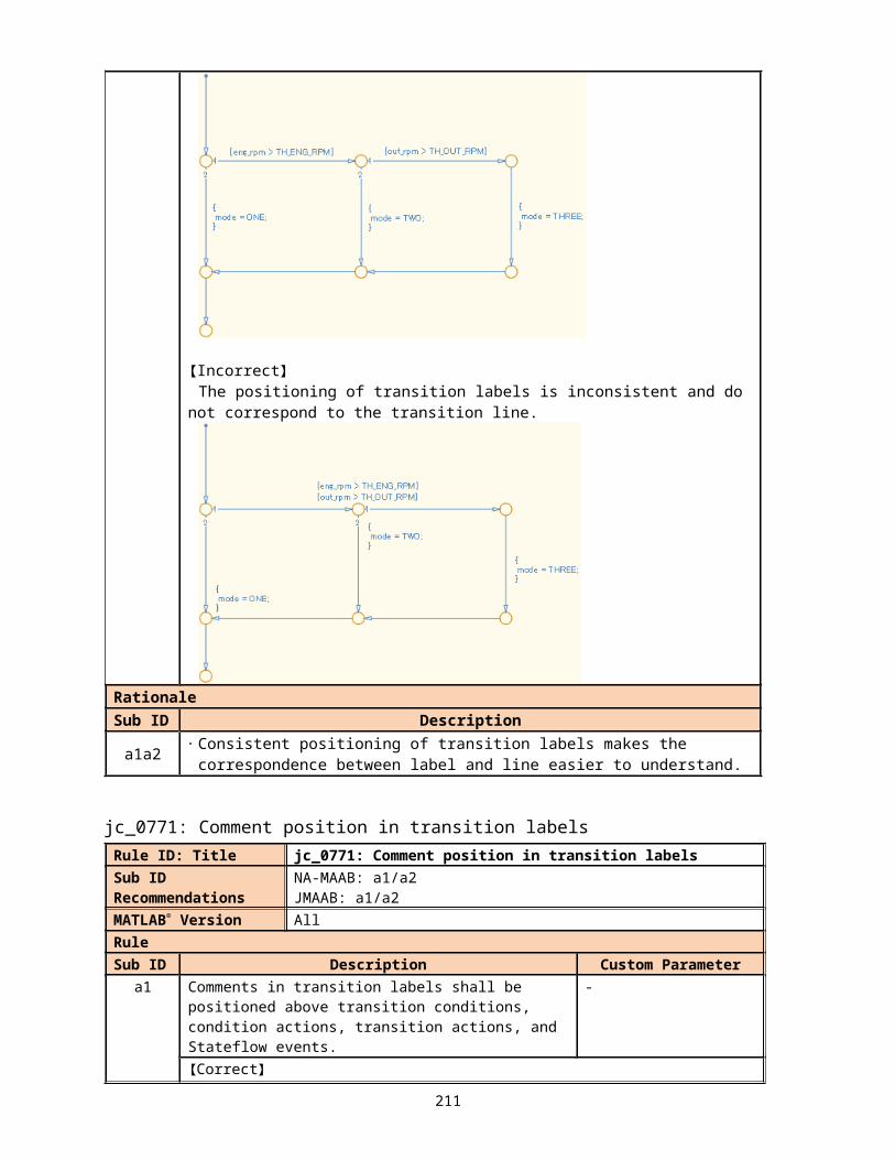
Conditional input block
Includes [Trigger], [Enable], [Function Call], and [Reset].
Delay block
Two meanings:1. The previous value reference block that is placed in the loop
route to specify the execution order in an algebraic loop (circular reference). Uses [Unit Delay] and [Memory]. (As of R201b at later) [Delay] blocks can also be used
2. A block that retains past values. Uses [Unit Delay], [Memory], [Delay], and [Tapped Delay].
Calculation block Blocks with “Sum” {BlockType} that carry out addition and subtraction operations. Includes [Sum], [Add], [Subtract], and [Sum of Elements].
Multiplication and division block
Blocks with “Product” {BlockType} that carry out division and multiplication operations. Includes [Product], [Divide] and [Product of Elements].
Stateflow block Includes [Chart], [State Transition Table], and [Truth Table].Machine level .
Flow chart
The part of a model that describes the action for the transition condition by using transition conditions and condition actions. The start point is the default transition line or internal transition line. The end point is the connective junction. Does not include states that are between the start and end points.Graphical functions and the inside of states can be modelled as flow charts.
State action type Basic state action types and combined state action types.Basic state action type
Types include entry(en), during(du), and exit(ex).
Combined state action type
A combination of two or more of these basic state action types: entry(en), during(du) during(du), exit(ex) entry(en), exit(ex) entry(en), during(du), exit(ex)
State An atomic subchart is considered a state.
211
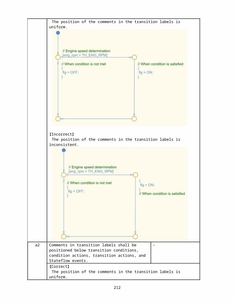
7. Determining Guideline Operation RulesThis section provides general information about identifying which guidelines to adopt and the application
of these guidelines to your project.
7.1. Process Definition and Development EnvironmentThe model base development that utilizes simulation is suitable for developing a safe product. However,
this does not mean that a system is safe simply because the design can be simulated. While high quality control and functions is necessary, the process definition and development environment being used is equally important. The foundation for a safe system is determined at the start of the project, long before development begins.
7.2. MATLAB/Simulink VersionThe version of MATLAB/Simulink used at each development stage is determined at the start of the
project. That version must be used by everyone during that development stage. Different MATLAB versions can be used for different stages in the development process. For example, you can generate and verify the code in R2017b and then use Simulink Design Verifier to develop test cases R2020a.
It is necessary to regularly check the bug report published by MathWorks (https://www.mathworks.com/support/bugreports). Depending on the bug, a version change may be required; a decision that can be reversed if necessary. During this evaluation, it is important to consider
risk from both: Malfunctions that result from a bug Result from upgrading the version.
It is necessary to always have a process that allows adaptation to the latest version and to appropriately evaluate and judge what is the safest option.
7.3. MATLAB/Simulink SettingsMATLAB/Simulink settings shall adhere to the project. It is important that Simulink settings that affect
appearance are applied consistently across the project.
Options to be unified are listed below. Simulink environment settings
o New model standard font settings (block, line, annotation) Mask (Edit mask)
o Icons and Ports Information display
o Library linkso Sample Timeo (Block) Sorted execution ordero (Signals and ports) Wide Non-scalar Lineso (Signals and ports) Port data types
See guidelines: na_0004 and db_0043
7.4. Usable BlocksThere are many blocks in Simulink, however, not all are suitable for all aspects of a project. For
example, only some blocks are suitable for generating production-quality code. Or, depending on the block, a function using a combination of basic blocks can be represented by using one block. Usable blocks and design should be defined and limited to the requirements and specifications of the project.
212
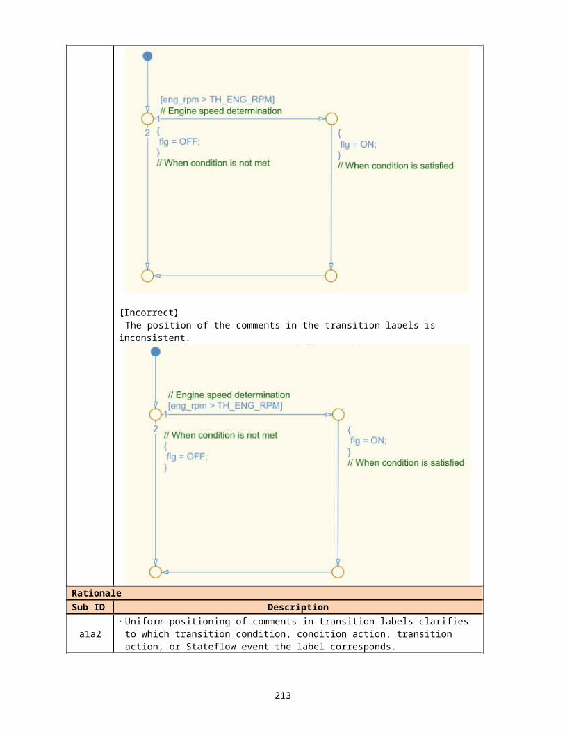
Note: Significantly limiting the number of available blocks can cause adverse effects, such decreased readability due to variation within the descriptions for the same function, decreased code efficiency, and increased user libraries.
Note: You must register custom blocks in the project’s user library.
See guideline db_0143 for defining usable blocks
7.5. Using Optimization and Configuration Parameters
Optimization parametersOptimization options significantly affect generated code. Closely evaluate and apply the optimization
options with regards to how they impact the security and safety considerations for your project or product.
An example of how optimization parameters can impact a process:For embedded automotive products, it is critical that processing time is fast and RAM/ROM
requirement are minimal. To accommodate these requirements, optimization parameters are applied on the “Conditional Input Branch Execution” pane. These optimization parameters improve the computation rate by executing only where the condition holds during execution of the conditional branch by using [Switch].
In contrast, for the aviation industry, this pane is disabled because stabilizing the execution speed is key. Calculation on both sides is preferred in order to maintain a stable computation time, even if calculation is needed only on the side where the condition holds.
Configuration Parameters Hardware implementation settings
Describes model system hardware characteristics, including products and test hardware configuration setup for simulation and code generation.
Configure these parameters so they are compatible with the microcomputer that the project uses. Unintended utility functions can be inserted if signed integer division rounding is undefined.
Model reference settingsSpecified when using model references.Refers to options to include other models in this model, options to include this model in another
model, and build options of simulation and code generation targets.
Simulation target settingConfigures a simulation target of a model with [MATLAB Function], [Stateflow], or [Truth Table].
High-integrity configuration SettingsPlease refer to the MathWorks High-Integrity System Modeling Guidelines (hisl) for additional information the configuration settings.
Code Generation Configuration SettingsPlease refer to the MathWorks Code Generation Modeling Guidelines (cgsl) for additional information the configuration settings
7.6. Applying Guidelines for a Project
Using the model analysis process when applying guidelinesModel design specification should be defined prior to reviewing the guidelines. Doing so makes the
process of determining which guidelines to apply and the implementation of the guidelines more efficient. For example, the analysis of a simple model can use [SLDiagnostics] to investigate how often a
specific block is used. Adjust the operation rules list by specifying blocks that are frequently used and those that aren’t.
Furthermore, reusability at a later stage is improved by adding rules that: Unify description styles
213
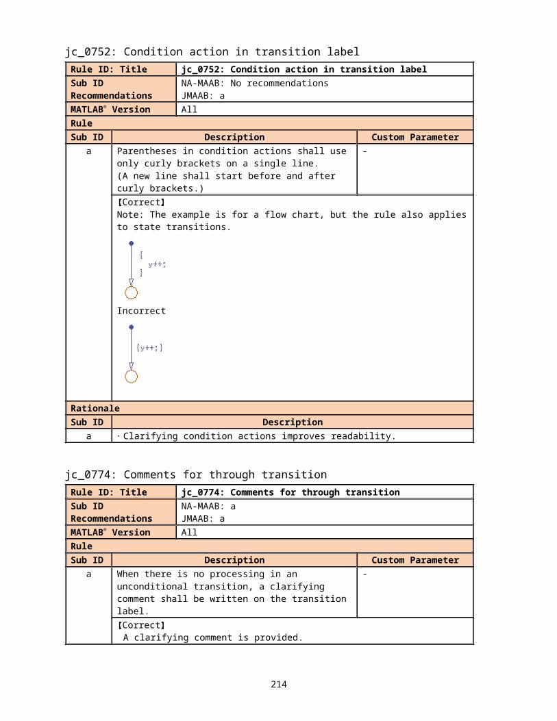
Anticipate in advance the man-hours needed to correct models Measuring tendencies, such as where to place blocks that have feedback status variables ([Unit
Delay]), whether [Unit Delay] should be inside or outside the subsystem, or whether [Abs] should be set on the output side of the subsystem, and if it should process at the input side after receiving a signal.
Adoption of the guideline rule and process settingsAt the start of the project, it should be determined which guidelines apply to each development
process. The guidelines should be evaluated and applied so that they correspond with the development process. Considerations may include questions such as:
Will the guideline be applied only at the code generation stage? Will the adopted guideline rule change for each process stage?
Setting the guideline rule application field and the clarifying the exclusion conditionThe field to which the guidelines apply must be determined. For example, guidelines can be: Limited to a model that represents the AUTOSAR field of application Applied to a general software field, such as where models implement interrupts (add processes
that prohibit interruption during calculation). Specific to fields where general engineers edit the models. The intention of these rules is to
ensure that the models are easily understandable in those fields. Note: Specialized fields can be excluded from the constraints of these guidelines by limiting the scope and applying unique set of guidelines that are specific in this environment.
Specialized fields, such as those where modelers design custom library blocks, are not fields that are typically targeted by these guidelines.
Furthermore, when having a control model that is operated with Rapid Control Prototyping (RCP), the entire model should not be set as a target; instead, the field needs to be limited. It is necessary to generate the code and review the areas that are implemented in the built-in microcomputer as well as the areas that are not. These guidelines do not apply to control models such as those scheduler models that are made solely for RCP and are not implemented, or for interface sections with blocks that correspond to drivers such as CAN and PWM signals for operating actual machines.
Parameter recommendations in the guidelinesGuidelines should not be adopted as they are written without further evaluation. Implementation of guideline rules and parameter recommendations should be evaluated to determine
the impact on the project and the development processes being used. In addition, consideration needs to be taken as to the effect on other guidelines and how applying custom parameters can affect simulation or code generation.
Verifying adherence to the guidelines At the beginning of a project, it is important to determine how and when the project will be evaluated to
ensure adherence to the guidelines. The decision whether to use an automated checking mechanism (third part or internal) or perform
manual checks is very important. Also, the stage at which the checks occur, as well as developing a system for revising the check rule criteria, is important.
Automated checking can significantly reduce the time required for review. It is recommended that an additional, manual review also be performed by a skilled person, even if everything can be checked automatically.
Modifying adherence to a guidelineThe decision to apply a guideline or a rule can change. When doing so, it is important to specify a
process and procedure for determine the root cause of the request and evaluate the potential impact the change can have on the project and the organization.
When evaluating the change request, first listen to the needs of the modeler and determine the root cause of the request. When the request is based on the user not understanding block usage or a guideline rule, training should occur instead of revising the rule.
214
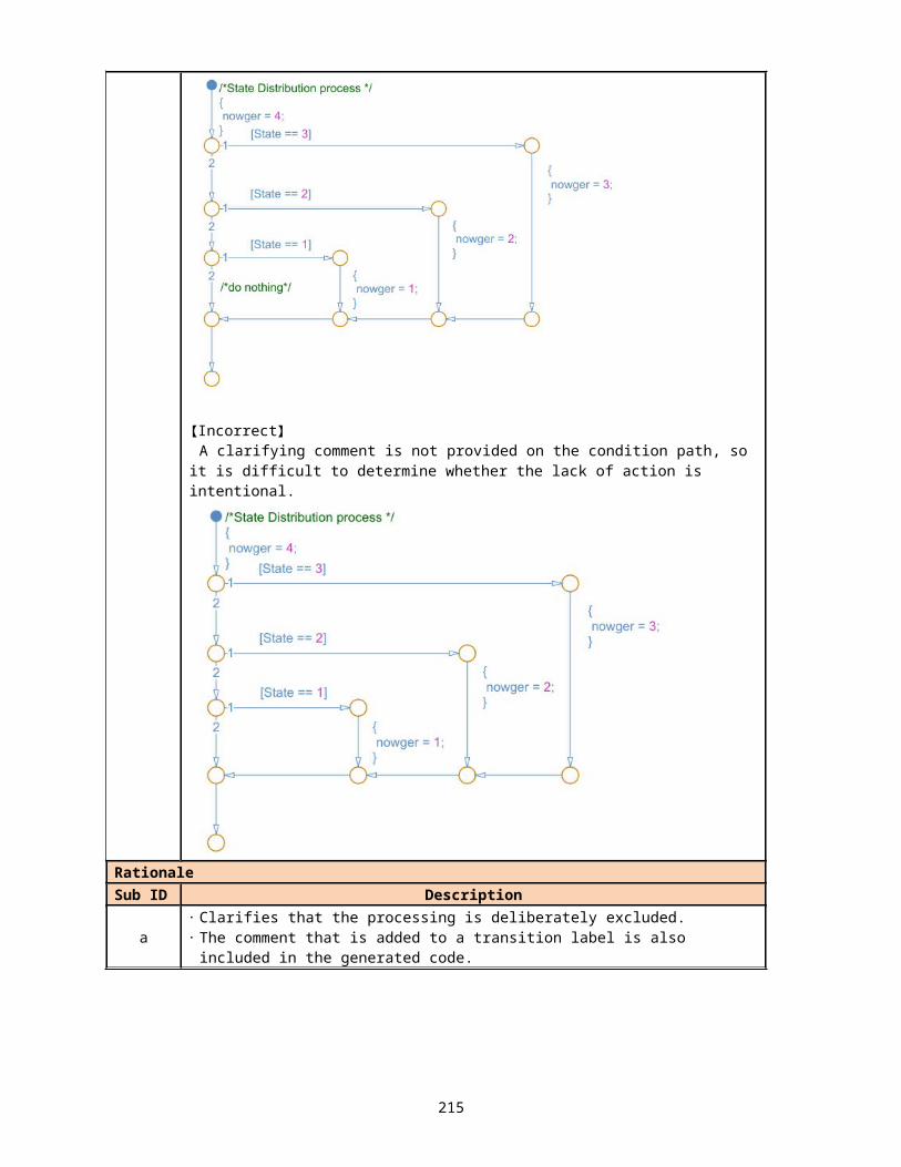
The procedure to relax the rules as needed should be implemented when there are restrictions due to company objectives and control specifications or hardware (such as microcomputers).
215
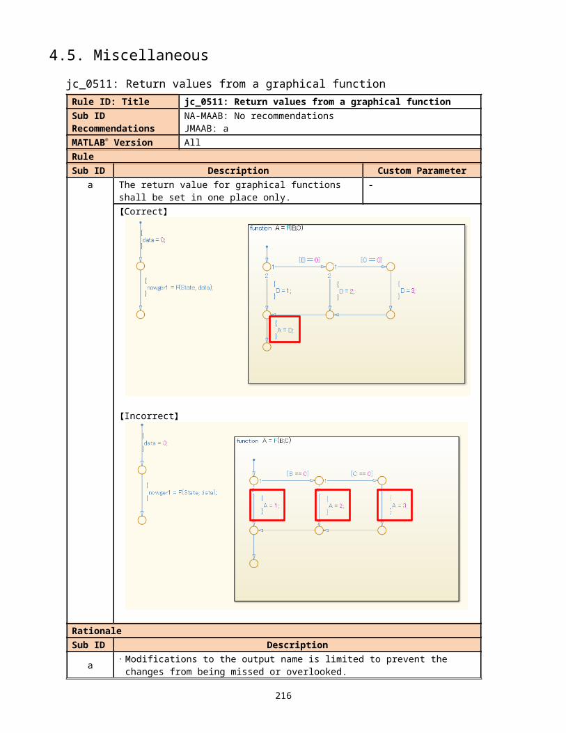
8. Model Architecture ExplanationThis section provides a high-level overview of model architecture that is suitable for model-based
development without specifying specific rules.
8.1. Roles of Simulink and StateflowWhen using Stateflow, Simulink is required for inputs, outputs, and structuring. Stateflow alone can
perform a variety of formula processing. When using Simulink, complex state variables can be realized through methods such as [Switch Case].
Either Simulink or Stateflow can be used to model specific parts of control, however, the application of either product in the development workflow is based on the user’s understanding of the underlying algorithms and, ultimately, comes down to the organization to determine which tool is best suited for their needs. Determining whether Simulink or Stateflow should be used for design should be determined by a group of people in accordance with the task. Whether implementation in Stateflow is done by using state transitions or with flow charts should also be specified.
In most cases, Stateflow is less efficient with regards to RAM. Therefore, Simulink has an advantage in computations that use simple formulas. In addition, Simulink is more advantageous for situations where state variables are operated with simple flip-flops and [Relay]. When evaluating whether to use Simulink or Stateflow in a project, these topics should be taken into consideration: Increasing RAM: There must always be a RAM available for visualization of Stateflow inputs, outputs
and internal variables. Equation error handling: When general computational formulas are used internally, the user designs
ways to prevent overflow. Splitting and separating functions: When performing calculations that use Simulink outside of
Stateflow, there is a possibility that they may split, thus reducing readability. There are also times where readability may improve. This can be difficult to judge.
There are cases where Stateflow has more efficient code than Simulink for optimum expressions that are close to code, but most of these result in a model that is difficult to understand. If code already exists, it is more advantageous to use S-functions instead of Stateflow modelling. Stateflow can note computations where specific arrangements are specified, or computations using for-loops, more efficiently than Simulink, but in recent years it has also become convenient to use MATLAB language for descriptions. If needed, consider using MATLAB language for modelling.
For Stateflow models, when dealing with states as described below, readability improves by describing them as state transitions:
Different output values are output for identical inputs. Multiple states exist (as a guide, three or more). States with meaningful names instead of just numbers. Inside a state, initialization (first time) and differentiation during execution (after the second time) is
required.For instance, in flip-flop circuits, different values are outputted for inputs. State variables are limited to 0
and 1. However, a meaningful name cannot be added to each state simply by retaining Boolean type numbers. There is also no distinction between initialization and execution within the state. Thus, only one flip-flop applies out of the four above, so Simulink can be said to be more beneficial.
In Stateflow, situations that can be represented as states are implemented as state transitions and conditional branches that are not states are implemented as flow charts. Truth tables are classified as a conditional branch implementation method.
When designing states as state transitions by using Stateflow, “Classic” should be selected as the state machine type so that it is implemented as software into the control system’s embedded micro controller.
HDL Coder is supported by Stateflow. If using HDL Coder, Mealy or Moore must be selected., Moore mode is more appropriate when protection is required against internal electric leaks.
Note: HDL Coder use cases are not described in these guidelines.
216
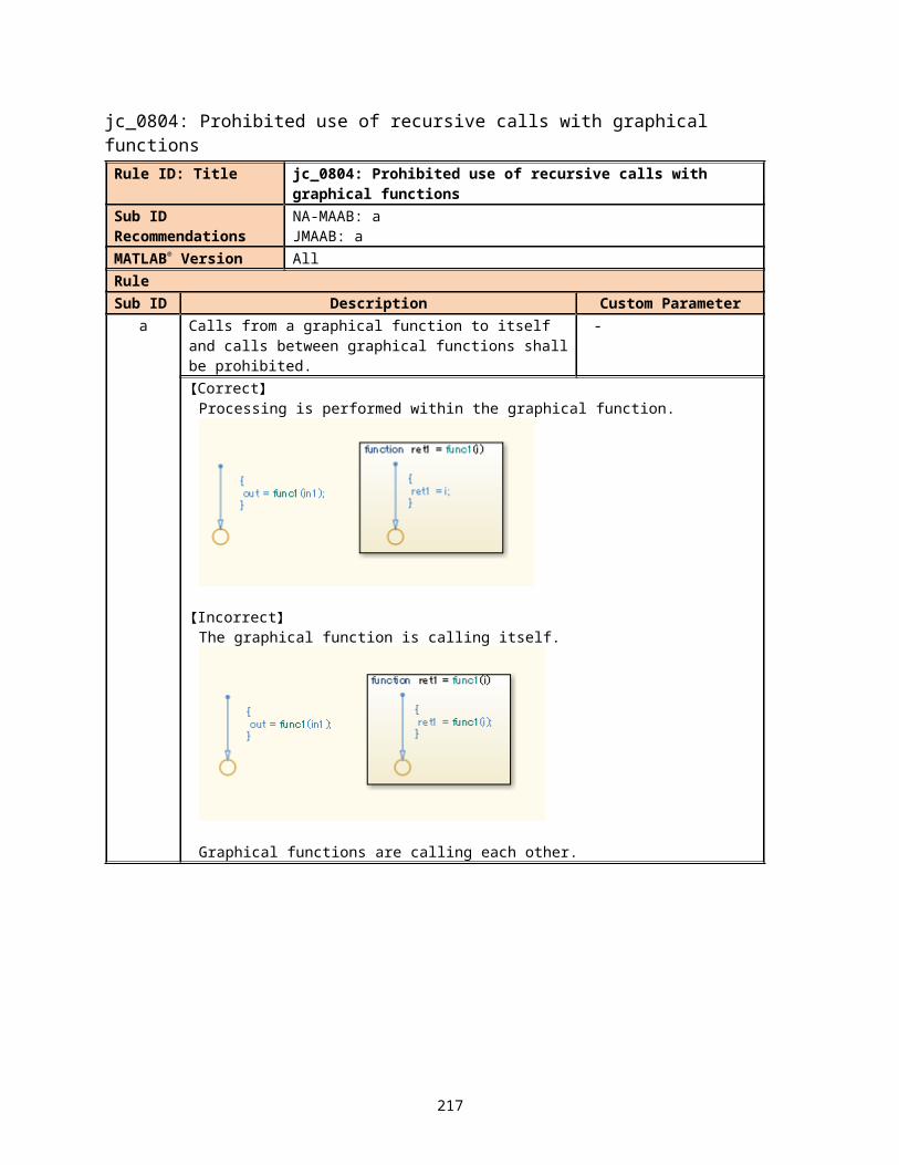
8.2. Hierarchical Structure of a Controller ModelThis section provides a high-level overview of the hierarchical structuring in a basic model, using a
controller model as an example.
Types of Hierarchies
This table defines the layer concepts in a hierarchy.Layer concept Layer purpose
TopLayer
Function layer Broad functional divisionSchedule layer Expression of execution timing (sampling, order)
BottomLayer
Sub function layer Detailed function divisionControl flow layer Division according to processing order (input →
judgment → output, etc.)Selection layer Division (select output with Merge) into a format
that switches and activates the active subsystemData flow layer Layer that performs one calculation that cannot
be divided
When applying layer concepts: Layer concepts shall be assigned to layers and subsystems shall be divided accordingly. When a layer concepts is not needed, it does not need to be allocated to a layer. Multiple layer concepts can be allocated to one layer.
When building hierarchies, division into subsystems for the purpose of saving space within the layer shall be avoided.
Top LayerLayout methods for the top layer include: Simple control model — Represents both the function layer and schedule layer in the same layer.
Here, function = execution unit. For example, a control model has only one sampling cycle and all functions are arranged in execution order
Complex control model Type α — The schedule layer is positioned at the top. This method makes integration with the code easy, but functions are divided, and the readability of the model is impaired.
Complex control model Type β — Function layers are arranged at the top and schedule layers are positioned below the individual function layers.
217
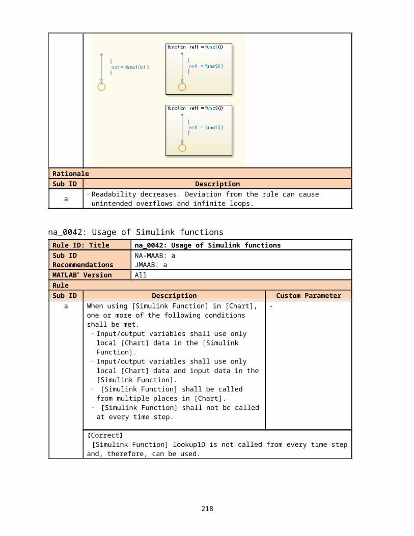
Schedule layer
Function layer
Schedule layer
Schedule layer
Function layer Function layer
S1C1
S2
C2
S1
S2
C1
C2
ExampleType α
ExampleType β
Subsystem for low speed operation
Subsystem for high speed operation
Sensing function subsystem Control function subsystem
Function Layers and Sub-Function LayersWhen modeling function and sub-function layers:
Subsystems shall be divided by function, with the respective subsystems representing one function.
‟One functionˮ is not always an execution unit so, for that reason, the respective subsystem is not necessarily an atomic subsystem. In the type β example below, it is more appropriate for a function layer subsystem to be a virtual subsystem. Algebraic loops are created when these change into atomic subsystems.
Individual functional units shall be described. When the model includes multiple large functions, consider using model references for each function
to partition the model.
The thick frame is an Atomic setting
218
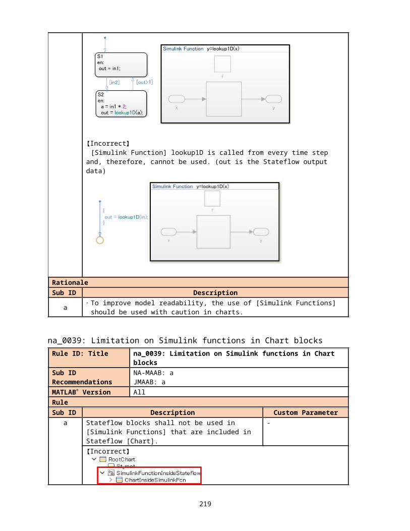
Schedule layer
Function layer
Schedule layer
Schedule layer
Function layer Function layer
S1C1
S2
C2
S1
S2
C1
C2
ExampleType α
ExampleType β
Subsystem for low speed operation
Subsystem for high speed operation
Sensing function subsystem Control function subsystem
Schedule LayersWhen scheduling layers:
System sampling intervals and execution priority shall be set. Use caution when setting multiple sampling intervals. In connected systems with varying sampling intervals, ensure that the system is split for each sampling interval. This minimizes the RAM needed to store previous values in the situation where the processing of signals values differs for fast cycles and slow cycles.
Priority ranking shall be set. This is important when designing multiple, independent functions. When possible, computation sequence for all subsystems should be based on subsystem connections.
Two different types of priority rankings shall be set, one for different sampling intervals and the other for identical sampling rates.
There are two types of methods that can be used for setting sampling intervals and priority rankings: For subsystems and blocks, set the block parameter {sample time} and block properties
{priority}. When using conditional subsystems, set independent priority rankings to match the scheduler.
Patterns exist for many different conditions, such as the configuration parameters for custom sampling intervals, atomic subsystem settings, and the use of model references. The use of a specific pattern is closely linked to the code implementation method and varies significantly depending on the status of the project. Models that are typically affected include:
Models that have multiple sampling intervals Models that have multiple independent functions Usage of model references Number of models (and whether there is more than one set of generated code)
For the generated code, affected factors include: o Applicability of a real-time OSo Consistency of usable sampling intervals and computation cycles to be implementedo Applicable area (application domain or basic software)o Source code type: AUTOSAR compliant - not compliant - not supported.o RAM, ROM margins (specifically RAM)
219
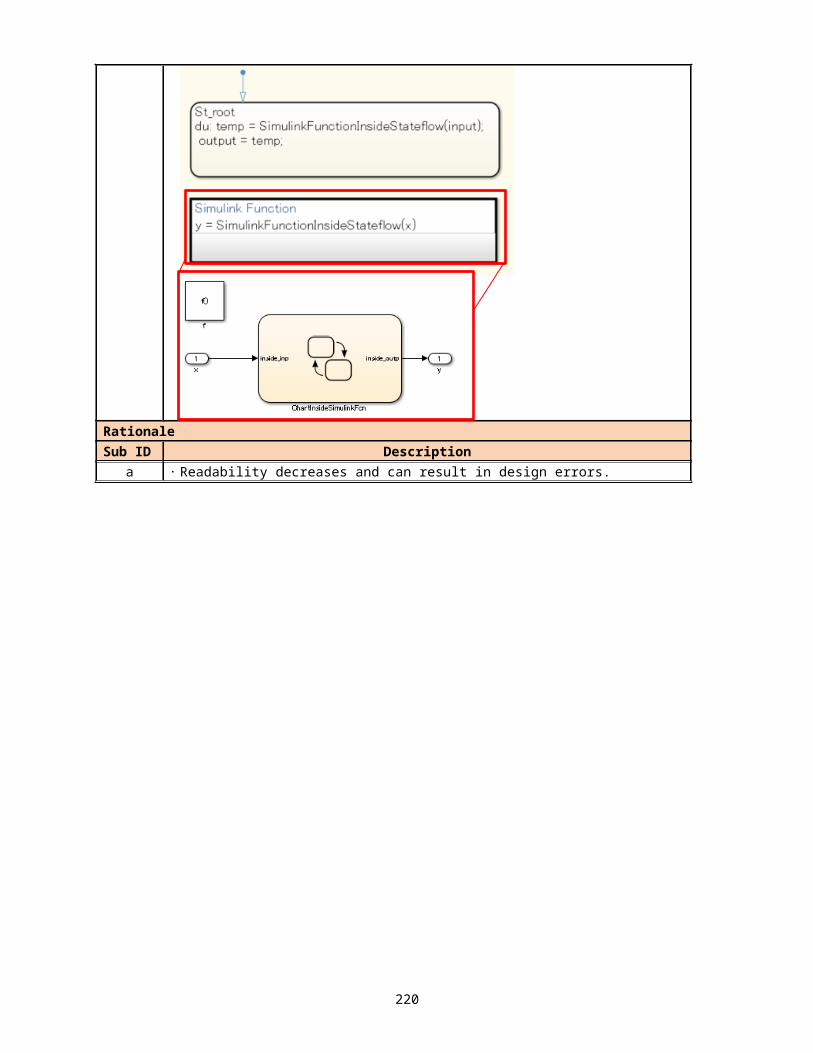
Control Flow LayersIn the hierarchy, the control layer expresses all input processing, intermediate processing, and output
processing by using one function. The arrangement of blocks and subsystems is important in this layer. Multiple, mixed small functions should be grouped by dividing them between the three largest stages of input processing, intermediate processing and output processing, which forms the conceptual basis of control. The general configuration occurs close to the data flow layer and is represented in the horizontal line. The difference in a data flow layer is its construction from multiple subsystems and blocks.
In control flow layers, the horizontal direction indicates processing with different significance; blocks with the same significance are arranged vertically.
Block groups are arranged horizontally and are given a provisional meaning. Red borders, which signify the delimiter for processing that is not visible, correspond to objects called virtual objects. Using annotations to mark the delimiters makes it easier to understand.
Control flow layers can co-exist with blocks that have a function. They are positioned between the sub-function layer and the data flow layer.
Control flow layers are used when:- The number of blocks becomes too large
Input processing
Intermediate processing
Output processing
Input processing
Intermediate processing
Output processing
220
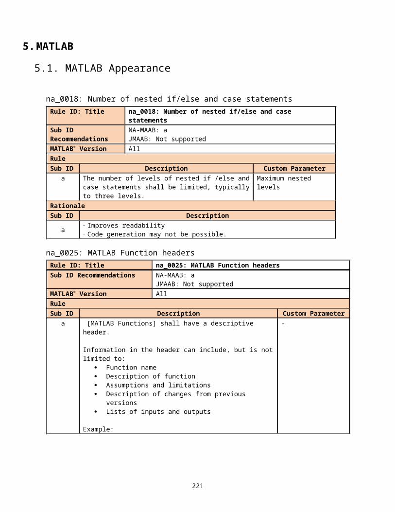
- All is described in the data flow layer - Units that can be given a minimum partial meaning are made into subsystems
Placement in the hierarchy organizes the internal layer configuration and makes it easier to understand. It also improves maintainability by avoiding the creation of unnecessary layers.
When the model consists solely of blocks and does not include a mix of subsystems, if the horizontal layout can be split into input/intermediate/output processing, it is considered a control flow layer.
Selection LayersWhen modeling selection layers: Selection layers should be written vertically or side-by-side. There is no significance to which
orientation is chosen. Selection layers shall mix with control flow layers.
When a subsystem has switch functions that allow only one subsystem to run depending on the conditional control flow inside the red border, it is referred to as a selection layer. It is also described as a control flow layer because it structures input processing/intermediate processing (conditional control flow)/output processing.
In the control flow layer, the horizontal direction indicates processing with different significance. Parallel processing with the same significance is structured vertically. In selection layers, no significance is attached to the horizontal or vertical direction, but they show layers where only one subsystem can run.
For example: Switching coupled functions to run upwards or downwards, changing chronological order Switching the setting where the computation type switches after the first time (immediately after
reset) and the second time Switching between destination A and destination B
The horizontal sequencecontrol flow layer
Layer with a conditional control flow layer description is represented as a selection layer.
221
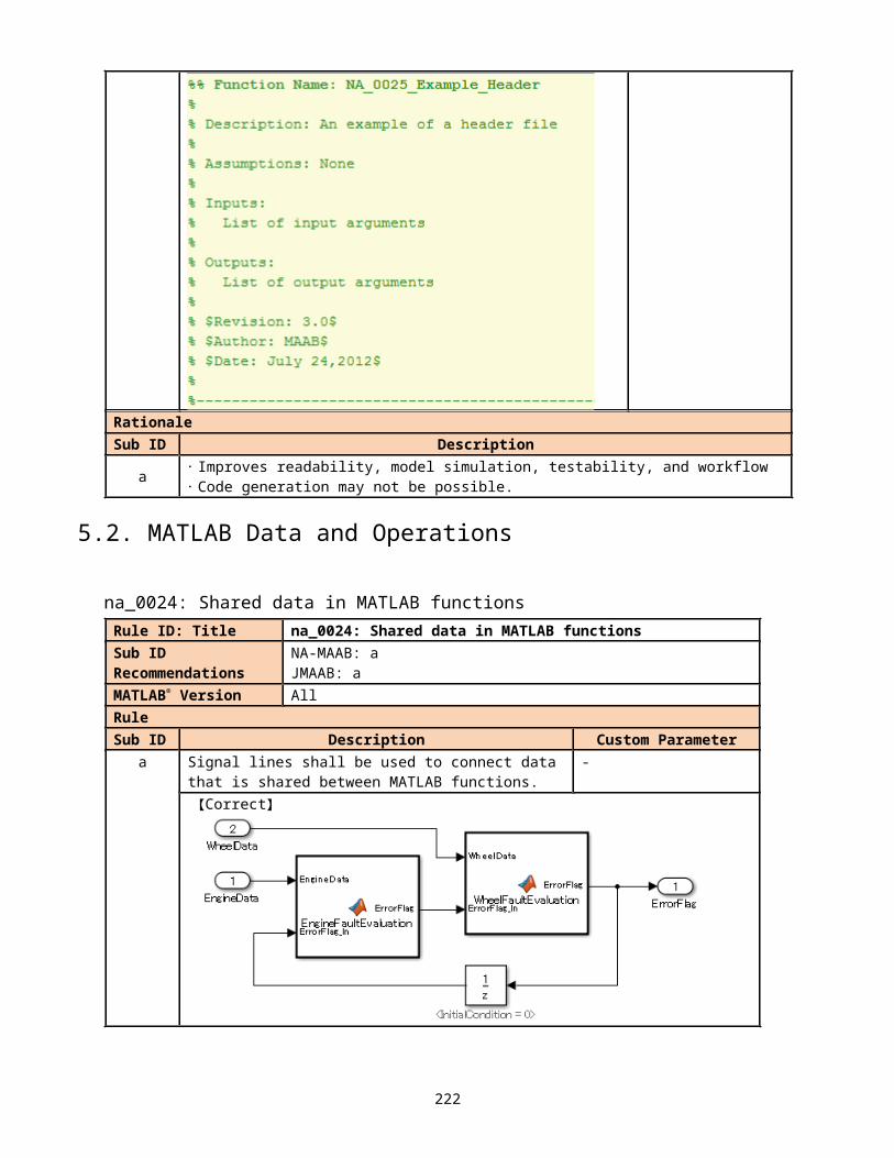
Data Flow LayersA data flow layer is the layer below the control flow layer and selection layer.A data flow layer represents one function as a whole; input processing, intermediate processing and
output processing are not divided. For instance, systems that perform one continuous computation that cannot be split.
Data flow layers cannot co-exist with subsystems apart from those where exclusion conditions apply. Exclusion conditions include: Subsystems where reusable functions are set Masked subsystems that are registered in the Simulink standard library Masked subsystems that are registered in a library by the user
Example of a simple data flow layer
Example of a complex data flow layer
When input processing and intermediate processing cannot be clearly divided as described above, they are represented as a data flow layer.
A data flow layer becomes complicated when both the feed forward reply and feedback reply from the same signal are computed at the same time. Even when the number of blocks in this type of cases is large, the creation of a subsystem should not be included in the design when the functions cannot be clearly divided. When meaning is attached through division, it should be designed as a control flow layer.
8.3. Relationship between Simulink Models and Embedded Implementation
Running an actual micro controller requires embedding the code that is generated from the Simulink model into the micro controller. This requirement affects the configuration Simulink model and is dependent on:
The extent to which the Simulink model will model the functions How the generated code is embedded The schedule settings on the embedded micro controller
The configuration is affected significantly when the tasks of the embedded micro controller differs from those modeled by Simulink.
222
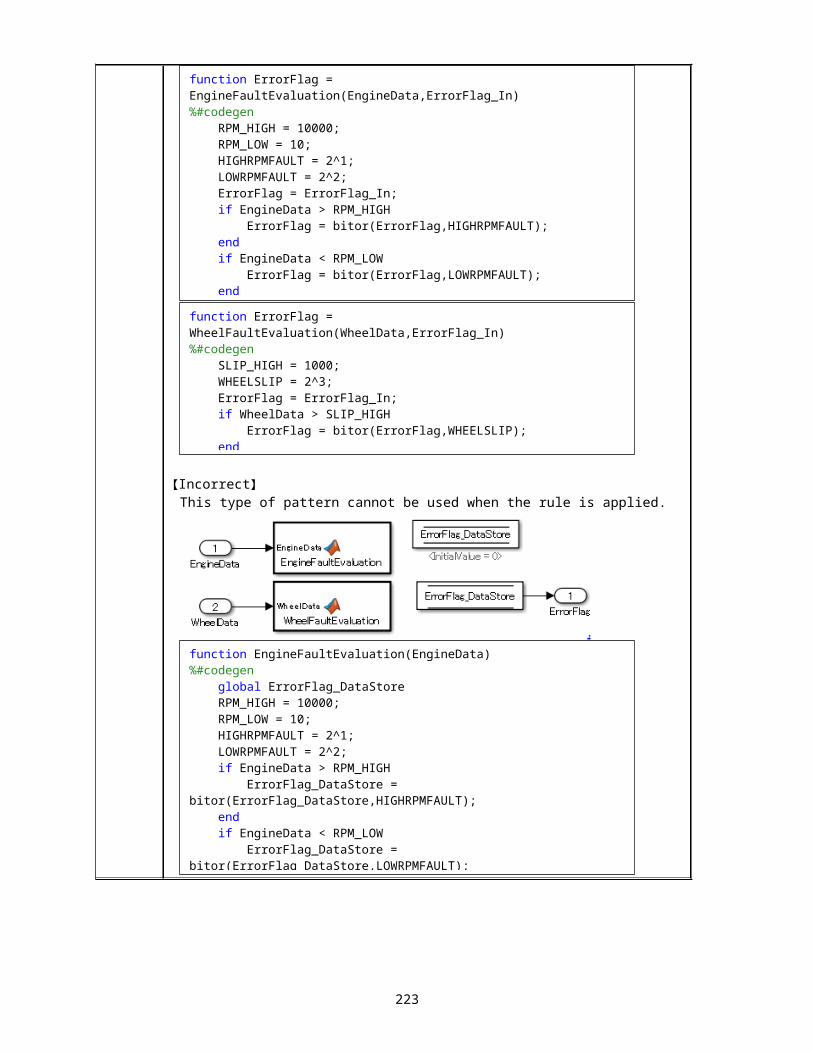
2msec
8msec
10msec
Function 1
Function 2-1 -2 -3 -4Function 3-1 -2 -3 -4 -5
All computations must be contained within the 2 msec cycle.
8.3.1.1. Scheduler Settings in Embedded SoftwareThe scheduler in embedded software has single-task and multi-task settings.
Single-task schedule settingsA single-task scheduler performs all processing by using basic sampling. Therefore, when processing
of longer sampling is needed, the function is split so the CPU load is as evenly distributed as possible, and then processed using basic sampling. However, as equal splitting is not always possible, functions may not be able to be allocated to all cycles.
For example, basic sampling is 2 msec, and sampling rates of 2 msec, 8 msec and 10 msec exist within the model. An 8 msec function is executed once for every four 2 msec cycles, and a 10 msec function is executed once for every five. The number of executions is counted every 2 msec and the sampling function specified by this frequency is executed. Attention needs to be paid to the fact that the 2 msec, 8 msec and 10 msec cycles are all computed with the same 2 msec. Because all computations need to be completed within 2 msec, the 8 msec and 10 msec functions are split into several and adjusted so that all 2 msec computations are of an almost equal volume.
The following diagram shows the 10 msec function split into 5, and the 8 msec function split into 4.
Functions Fundamental frequency
Offset
8msec 0msec2-2 8msec 2msec2-3 8msec 4msec2-4 8msec 6msec
Functions Fundamental frequency
Offset
3-1 10msec 0msec3-2 10msec 2msec3-3 10msec 4msec3-4 10msec 6msec3-5 10msec 8msec
To set frequency-divided tasking:1. Set configuration parameter {Tasking mode for periodic sample times} to “Single Tasking” for
Simulink task setting.
223
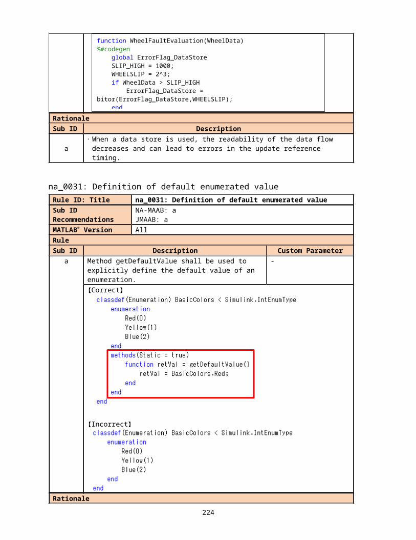
Function 3
2msec
8msec
10msec
Function 1
Function 2
2. Enter sampling period, offset” values in the subsystem block {Sample Time}” field. A subsystem for which a sampling period can be specified is an atomic subsystem.
Multi-task scheduler settingsMulti-task sampling is executed by using a real-time OS that supports multi-task sampling. In single-
task sampling, equalizing the CPU load is not done automatically, but a person divides the functions and allocates them to the appointed task. In multi-task sampling, the CPU performs the computations automatically in line with the current status; there is no need to set detailed settings. Computations are performed and results are output starting from the task with the highest priority, but the task priorities are user-specified. Typically, fast tasks are assigned highest priority. The execution order for this task is user-specified.
It is important that computations are completed within the cycle, including slow tasks. When the processing of a high priority computation finishes and the CPU is available, the computation for the system with the next priority ranking begins. A high priority computation process can interrupt a low priority computation, which is then aborted so the high priority computation process can execute first.
224
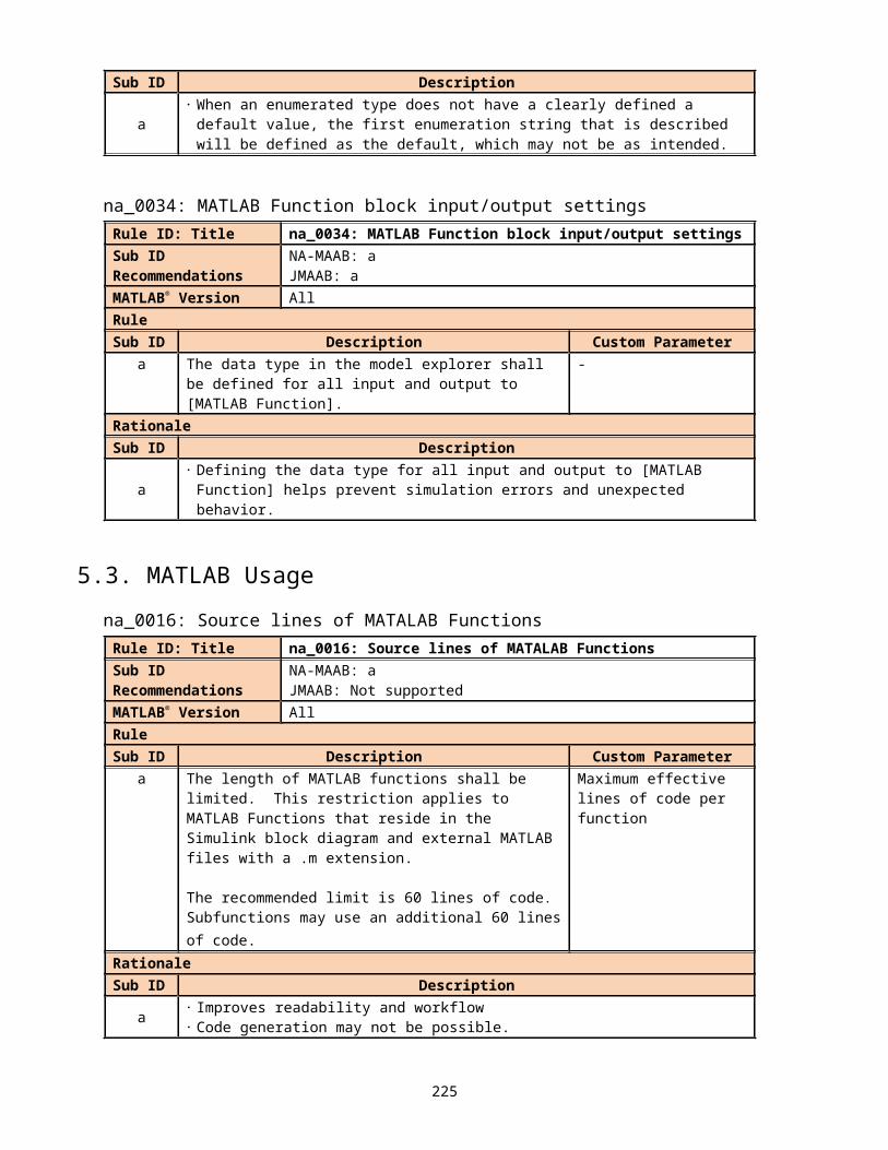
A different RAM should be allocated for signal values with a different rate.
If Function 2 uses computation results of Function 1, computation results for Function 1 do not change during computation for Functions 2-1, 2-2, 2-3, but there is a possibility that Functions 2-1, 2-2, 2-3 use different values that have been computed on the respective different time axes.
8.3.1.2. Effect of Connecting Subsystems with Sampling DifferencesIf subsystem B with a 20 msec sampling interval uses the output of subsystem A with a 10 msec
sampling interval, the output result of subsystem A can change while subsystem B is computing. If the values change partway through, the results of subsystem B’s computation may not be as expected. For example, a comparison is made in subsystem B’s first computation with the subsystem A output, and the result is computed with the conditional judgment based on this output. At this point, the comparison result is true. It is then compared again at the end of subsystem B; if the output from A is different, then the result of the comparison can be false. Generally, in this type of function development it may happen that the logic created with true, true has become true, false, and an unexpected computation result is generated. To avoid this type of malfunction, when there is a change in task, output results from subsystem A are fixed immediately before they are used by subsystem B as they are used in a different RAM from that used by the subsystem A output signals. In other words, even if subsystem A values change during the process, the values that subsystem B are looking at is in a different RAM, so no effect is apparent.
When a model is created in Simulink and a subsystem is connected that has a different sampling interval in Simulink, Simulink automatically reserves the required RAM.
However, if input values are obtained with a different sampling interval through integration with hand-coded code, the engineer who does the embedding work should design these settings. For example, in the RTW concept using AUTOSAR, different RAMs are all defined at the receiving and exporting side.
Single-task scheduler settingsSignal values are the same within the same 2 msec cycle, but when there are different 2 msec cycles,
the computation value differs from the preceding one. When Function 2-1 and 2-2 uses signal A of Function 1, be aware that 2-1 and 2-2 uses results from different times.
Multi-task scheduler settingsFor multi-task, you cannot specify at what point to use the computation result to use. With multi-task,
always store signals for different tasks in new RAM.Before new computations are performed within the task, all values are copied.
2msec
8msec
10msec
Function 1
Function 2 -1 -2 -3 -4
Function 3 -1 -2 -3 -4 -5
225
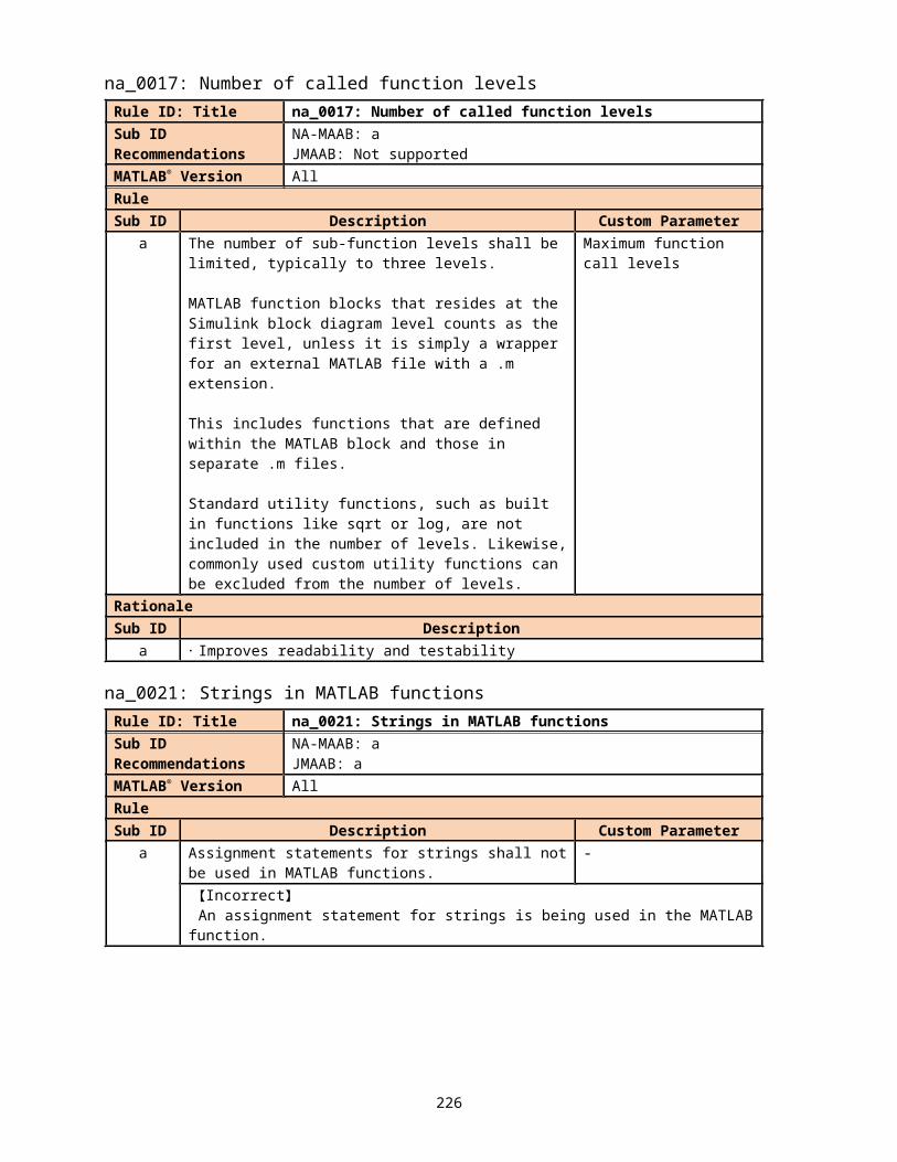
Function 3
If Function 2 uses computation results of Function 1, it is possible that computation results from Function 1 will replace them while Function 2 is computing.For that reason, computation results that vary at the point when computation starts for each sampling are generally stored in a different RAM.The value should be held at the
beginning of the task.
Do not immediately use values that are being updated.
2msec
8msec
10msec
Function 1
Function 2
226
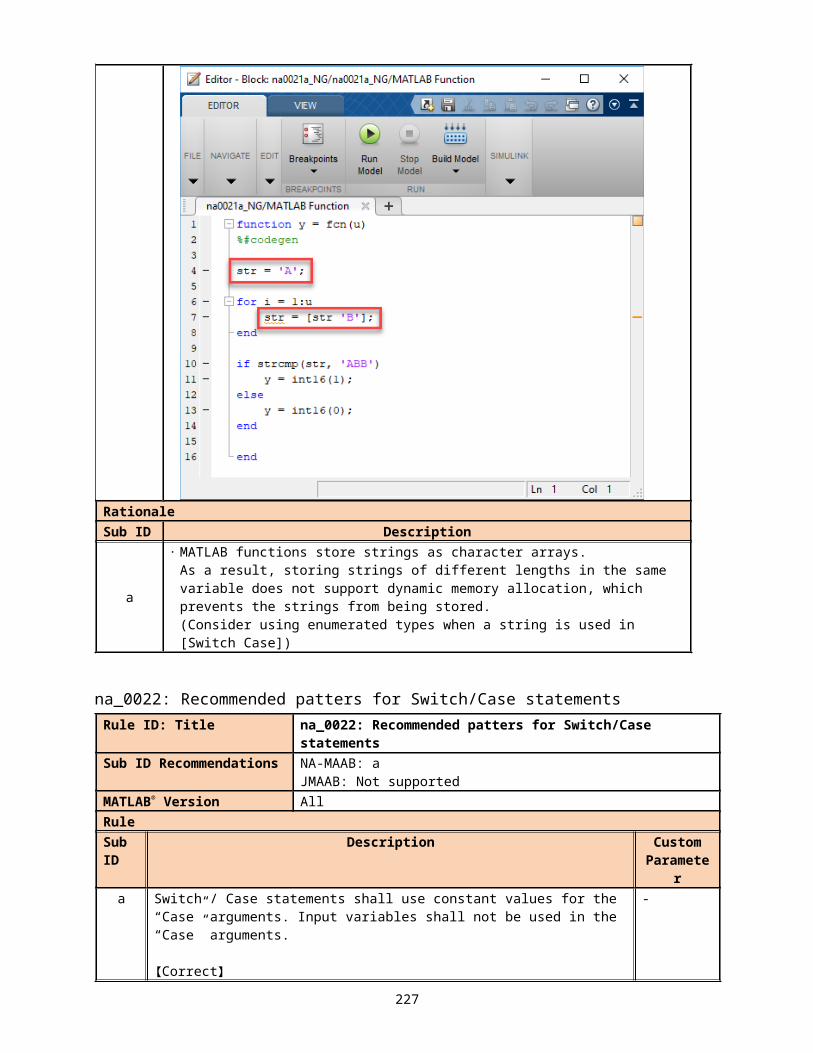
9. Appendices
9.1. Simulink Functions
9.1.1.1. Blocks with State VariablesBlocks with state variables are primarily grouped into Simulink and discrete types.For most of these blocks, the user can set the state attributes and initial values by using the block
parameters. A conditional subsystem can have state variables, depending on the structure pattern.
In this example, [Unit Delay] has State Attributes.
In this example, [Tapped Delay] does not have State Attributes.
227
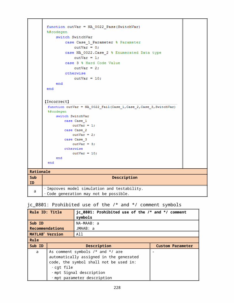
See guideline: jc_0640
9.1.1.2. Branch Syntax with State Variables[Switch] and conditional subsystems behave differently when state variables are used.Depending on the configuration setting, when any state variable exists, [Switch] generally executes
subsystem A when the condition of the control port is satisfied. If the condition is not satisfied, it executes only subsystem B without calculating subsystem A. However, when the subsystem A contains a state variable, calculation for the state variable within the subsystem A is processed even when the conditions of the control port are not satisfied.
~= 0
Switch
1In1
A
A
B
B
1Out1
In the conditional subsystem, subsystem A is calculated when the condition is satisfied. When is not satisfied, subsystem B is calculated instead of subsystem A, regardless of the existence of any state variables in subsystem A.
1In1
1Out1
u1if(u1 ~= 0)
else
If
A
A
B
B
Merge
Merge
The reset action in a recalculation can be specified by using the {Action Port} setting.
The behavior of subsystem A when using [Switch] and a conditional control flow is listed in the following tables. Familiarize yourself with these behaviors to determine which structure, [Switch], or conditional subsystem is most suitable for the intended purpose.
Behavior of subsystem AControl port condition
(in subsystem A)State variables
Switch Conditional subsystem
Hold No Executed ExecutedYes
Not hold No Not executed Not executedYes Minimally-processed
*Executed calculations related to the state variables
Initialization timing of subsystem AActionPort Initialize
Switch - First time only
228
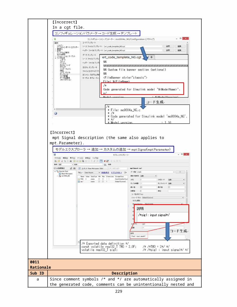
Conditional subsystem Hold First time onlyReset At returned by condition
See guidelines: jc_0656 and jc_0657
9.1.1.3. SubsystemA subsystem is used for compiling various blocks and subsystems.
Subsystems can also be used for other purposes. Usage methods that are not functional subsystems include: Mask display of the subsystem is used to describe the outline or display fixed form documents,
such as "classified" The open functions (callback functions in the block properties) of the subsystem is used for
running several tools or displaying explanatory text separate from the model Subsystems whose setting have changed to a mask subsystem (a subsystem that was simply
set to NoReadOrWrite) by a user with administrative rights to make a change, but other users cannot see the content.
These non-typical subsystems are outside of the scope of the guidelines and, if excluded, should be put on an exclusion list managed within the project.
See guidelines: jc_0201, jc_0243, db_0143, db_0144, db_0141, jc_0653, jc_0171, jc_0602, jc_0081, db_0081
9.1.1.4. Signal NameSignals can be named and are referred to as signal names. When a signal is named, that signal
name is displayed as a label. Updates to labels are reflected in the signal name and are also displayed.
The signal name can be propagated to a signal line via a branched signal line or port block and displayed as a signal name.
See guidelines: jc_0222 and jc_0245
Code can be generated by associating a signal name with a signal object (Simulink object or mpt object). Type setting is configured through the data dictionary, setting of the storage class is optional. The recommended data type settings for these blocks include: For [Inport], set the {Data type} to ”auto” For [Outport], set the {Data type} to ”auto” For [Sum], set the output {Data type} to ”Inherit via back propagation”
See guideline: jc_0644
9.1.1.5. Vector Signals/Path SignalIndividual scholar signals that compose a vector shall have common functions, data type, and units.
Signals that do not fulfill the conditions as a vector can only be grouped as a bus signal. [Bus Selector] shall be used only with bus signal inputs. It shall not be used to extract a scholar signal from a vector signal.
ExampleThe following is an example of a vector signal:
Types of vector Size
Row vector [1 n]
Column vector [n 1]
Wheel speed subsystem [1 wheel number]
229

Types of vector Size
Cylinder vector [1 cylinder number]
Location vector based on a 2-dimensional coordination
points
[1 2]
Location vector based on 3-dimensional coordination
points
[1 3]
The following is an example of a bus signal:Bus type Factor
Sensor bus Force vectors
Location
Wheel speed vector [Θlf, Θrf, Θlr, Θrr]
Acceleration
Pressure
Controller bus Sensor bus
Actuator bus
Serial data bus Circulating water temperature
Engine speed, front passenger seat door open
See guidelines: na_0010, jc_0222, jc_0245, db_0097, jc_0630, and jc_0659
9.1.1.6. Enumerated Types"Enumerated type data refers to data that is restricted to a determined numerical value.The type of blocks that can be used in an enumerated type in Simulink is limited.To use an enumerated type, you must define the enumerate type by using .m file on MATLAB. For
additional information about defining enumeration data types, refer to the Simulink user help “Use Enumerated Data in Simulink Models.
9.2. Stateflow Functions
9.2.1.1. Operators Available for StateflowFor additional information about the Stateflow operators, see “ Supported Operations for Chart Data”
in the Stateflow user help. Related ID: na_0001, jc_0655
9.2.1.2. Differences Between State Transition and Flow ChartStateflow can represent both a state transition and a flow chart.
Stateflow allows a flow chart to be designed within a state transition diagram.An entry action is represented as a flow chart in a state, which starts from a default transition and
moves to junctions through transition lines, as illustrated below. Starting from an internal transition line allows a during action to be represented in the flow chart.
A flow chart cannot maintain its active state between updates. As a result, a flow chart always ends at a “terminating junction” (a connective junction that has no valid outgoing transitions).
In contrast, a state transition diagram stores its current state in memory to preserve local data and active state between updates. As a result, state transition diagrams can begin executing where they left off in the previous time step. This means that state transitions are suitable for modeling reactive or supervisory systems that depend on history.
230
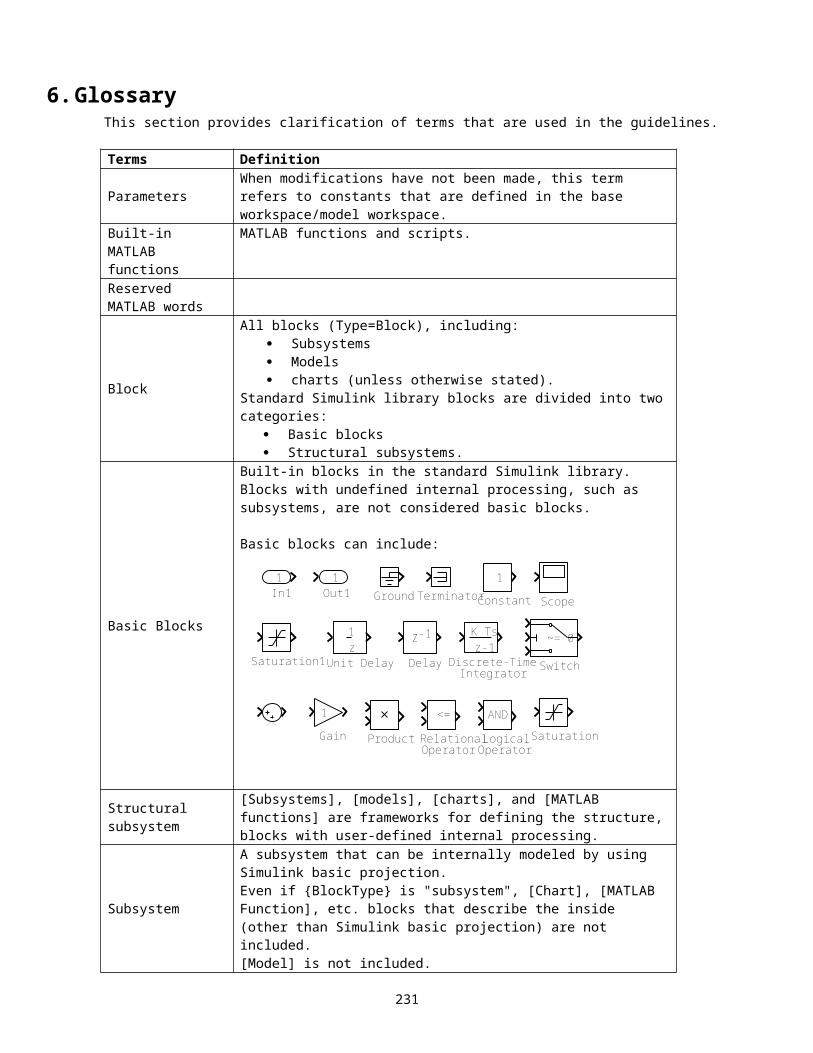
Flow chart and state transition diagramStart point End point
Flow chart Default transitionOr,
All terminations from the state are connected to the connective junction.
State transition diagram
Default transitionOr,
Either termination should be connected to the state
Difference between a general flow chart and state transition diagram
Flow Chart
Flow chart outside a state Flow chart inside a state
State Transition Diagram
State transition outside a state State transition inside a state
Mixture of flow charts and state transition diagrams with self-transition has more strict constraints.
Example of flow chart with self-transitionState Transition Diagram
Self transition outside a state Self transition inside a state
231
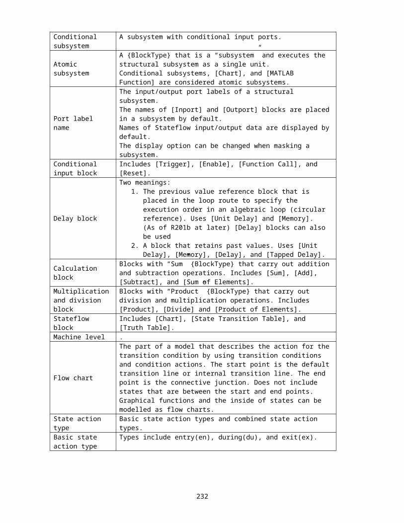
State transition diagram
A self transition is formed outside a state and then reset after execution.
A self transition is formed inside a state and then reset using a during action.
See guidelines: db_0132 and jc_0752
9.2.1.3. BacktrackThis example shows the behavior of transitions with junctions that force backtracking behavior in flow
charts. The chart uses implicit ordering of outgoing transitions.
Initially, state A is active and transition conditions c1, c2, and c3 are true and c4 is false:1. The chart root checks to see if there is a valid transition from state A.
There is a valid transition segment marked with the transition condition c1 from state A to a connective junction.
2. Transition condition c1 is true, so action a1 executes.3. Transition condition c3 is true, so action a3 executes.4. Transition condition c4 is not true and, therefore, the control flow backtracks to state A.5. The chart root checks to see if there is another valid transition from state A.
There is a valid transition segment marked with the transition condition c2 from state A to a connective junction.
6. Transition condition c2 is true, so action a2 executes.7. Transition condition c3 is true, so action a3 executes.8. Transition condition c4 is not true and, therefore, the control flow backtracks to state A.9. The chart goes to sleep.
To resolve this issue, consider adding unconditional transition lines to terminating junctions.The terminating junctions allow flow to end if either c3 or c4 is not true. This design leaves state A
active without executing unnecessary actions.
232

See guidelines: jc_0751 and jc_0773
9.2.1.4. Flow Chart Outside the StateA flow chart associated with a state can be written inside or outside of the state; however, be
attentive to the execution order and backtracking.The following flow chart, which evaluates transition from a to b after executing the flow chart outside
the state, appears to execute the transition within the same period as that of a newer calculation.However, the transition line to b is not evaluated if the termination point is reached by calculating the
transition outside the state. This is a state transition diagram which always stays at a.
a
b
{ nowger = 2;}
2
[State == 2]1
[State == 1]1
{ nowger = 3;}
2
{ nowger = 1;}
[State == 3]1
{ nowger = 4;}
1
/* */何もしない2
[nowger == 3]2
Done correctly, as with the line below, embed a transition condition that is intentionally not positioned at the termination of the external flow chart; it should be described so that the transition line from a to b is evaluated after the flow chart has been executed.
This enables the external flow chart to execute before the transition, and to be evaluated using the most recent value at the instant of the transition. Note that this chart contains a dead path where the transition condition will never hold, which can cause an error when the specification is changed in the future. Use this chart structure with caution.
233
In contrast, the following flow chart is inside a state, which means that the internal flow chart is always calculated when executing state a and can be described as an easily comprehensible structure without dead paths.
However, it should be noted that, as a performance characteristic, when state a is executed, the transition from a to b is evaluated in the cycle following that in which the internal flow chart is calculated.
Due to this characteristic, the timing of the execution of calculations and transitions for the external flow chart may be off. Use with caution.
{ nowger = 1;}
[State == 1]1
{ nowger = 4;}
{ nowger = 2;}
[State == 2]1
{ nowger = 3;}
2
2
[State == 3]1
{ nowger = 4;}
/* */何もしない2
a
b
内部遷移で実行させると、外部遷移評価後に実行されるので、1周期遅れて遷移する
[nowger==3]
See guidelines: jc_0751 and jc_0773
234
9.2.1.5. Pointer VariablesDescribe using the example model sf_custom.
gMyStructVar is not defined in Stateflow.Loading of C source code is set on the Code Generation pane of Configuration Parameter.Normally, functions of my_function are called from C source for use in Stateflow.However, direct reference to global variables exposed by the C source is also available from
Stateflow.
---------my_header.h--------------#include "tmwtypes.h"
extern real_T my_function(real_T x);
/* Definition of custom type */typedef struct {real_T a;int8_T b[10];}MyStruct;
/* External declaration of a global struct variable */extern MyStruct gMyStructVar;extern MyStruct *gMyStructPointerVar;
---------------my_function.c--------------#include "my_header.h"#include <stdio.h>
/* Definition of global struct var */MyStruct gMyStructVar;MyStruct *gMyStructPointerVar=NULL;
real_T my_function(real_T x){real_T y;
y=2*x;
return(y);}
------------------------Inside of Stateflow -----------------------------
235
9.3. Initialization
9.3.1.1. Initial Value Setting in InitializationWhen a signal needs to be initialized, the initial values shall be set correctly.When initial values are set inside a block, use an initial value list that includes annotations so you can visually confirm the initial values input.
Cases that require initial values include: When state variables are defined AND blocks that have state variables are used.
o Use the internal block settings.o Use the external input values.
When state variables are defined AND initial values are enabled for a block when a specific configuration is performed.
o Set initial values in Merge blocks.o Use signals registered in the data dictionary.
When signal settings (with RAM) have been defined that can be referenced from the outside.o Use signals registered in the data dictionary.
9.3.1.2. Initial Values of Signals Registered in the Data DictionarySet initial values for signals registered in the data dictionary.
Discrete block groups, such as [Unit Delay] and [Data Store Memory] have state variables.In the case of automatic code generation, the signal name, type, and initial value can be set for state variables by matching it to the signal in the data dictionary (associated with Simulink signal objects). When using a signal defined in the data dictionary for a state variable, the respective initial values should conform to the same value.
When using a signal defined in the data dictionary for a state variableFor discrete blocks, such as a [Unit Delay] and [Data Store Memory], settings are performed not when using signals defined in the data dictionary for the block output line, but for the state variables inside the block. Even when the signal name of the data dictionary is assigned to the signal line, RAM is reserved in duplicate, which is a waste of RAM.
【Correct 】 When the signal is defined for the state variables inside the block.
【Incorrect 】 When the signal is defined for the output signal of the block that has state variables.
236
x0
uZ-2
Delayx0
uZ-1
Resettable Delay
z1
Unit Delaydouble
1In1
double
Add
double1
Out1
y_k_1_Signal
Signal line properties setting
Unit Delay properties setting
z1
Unit Delaydouble
1In1
double
Add
double 1Out1
y_k_1_Signal
Signal line properties setting
Unit Delay properties setting
Signal objects that are defined in the Workspace can be automatically associated with signal objects and signal names of the same name by using disableimplicitsignalresolution (model name. However, for state variables inside the block, they are associated with the state variables inside the block and the signal name of the same name. If a globally set signal is associated with two variables at the same time, it is better to perform settings so that the state variables inside a block and the signal label on the signal line have different names, otherwise the model cannot be simulated.
9.3.1.3. Block Whose External Input Value is the Initial Value
When setting the initial value during initialization, the init function is called to set the signal to either the value inside of the block or to the initial value that is defined in the data dictionary.
Next, the step function (the data flow executive function) is executed. Here, the external input value is set as the initial value.
When modelling, be attentive to the execution functions and execution timing for initialization.
237
Initialization explanation
init functionSet the specified initialvalue to the signal
step function
Set the external input value only for the first time
step function
1 sampling
Differences in code behavior
step function
Required computation to compute external input value
Do not executeafter the second time
function
function Functions
9.3.1.4. Initial Value Settings in a System Configuration that Would Enable Initialization Parameters
There are system configurations where, depending on their settings, initialization parameters are enabled for combinations of conditional subsystems and [Merge]. When initial values are required in theses combinations, either of the following modeling methods is performed: Set in [Outport] Set in [Merge] If an mpt signal is defined behind [Merge], set in mpt signal
Exception: When there are successive blocks with initial values and the settings for each block are not needed
to clearly show the signal’s initial value.
【Correct 】 Initial value set in [Merge]
238
【Correct 】 Initial value set in mpt object
【Incorrect 】 Despite the requirement for an initial value setting, it is not shown anywhere.
239
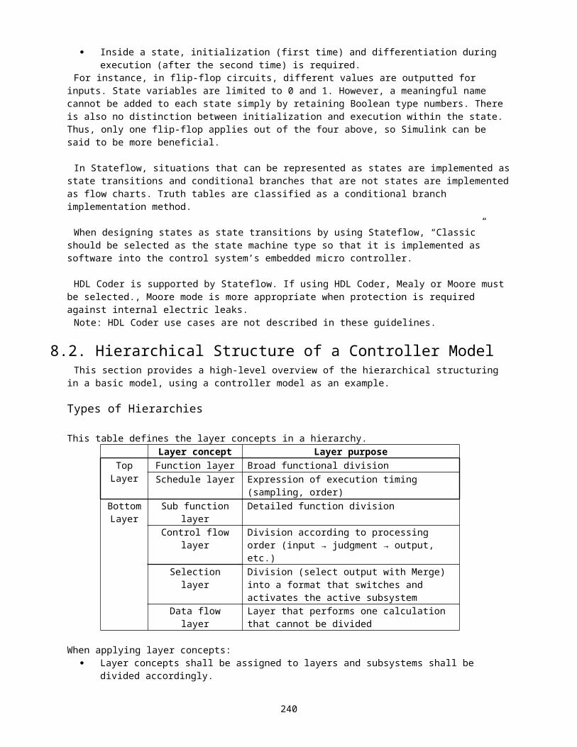
9.4. Miscellaneous
9.4.1.1. Atomic Subsystems and Virtual SubsystemsThere are two types of subsystems, Virtual subsystem and Atomic subsystems. The primary
difference between these subsystems is whether the subsystem is treated as a single execution unit. The virtual subsystem is the default subsystem block.
In a model, the border for a Virtual subsystem is thin as compared the border for the Atomic subsystem, which is thick and bold.
In1 Out1
Atomic Subsystem
In1 Out1
Virtual Subsystem
For additional information, in the Simulink user help see: Subsystems Explanation of algebraic loops
Virtual SubsystemA block that provides a visual representation is known as a "virtual block. ". For example, [Mux] that compiles several signal lines, [From] that hands out the signal, and [Goto] blocks all correspond to a virtual block. Since the subsystem block in the default setting only constitutes a visual hierarchical structure, these blocks are considered virtual blocks. The subsystem is referred to as a virtual subsystem.
Consider a subsystem that consults an external calculation result within a subsystem, as shown in the following example. This system is calculated from these four equations.temp1= in1 + in2temp2= in3 + in4out1= in1 + in2 + temp2
240
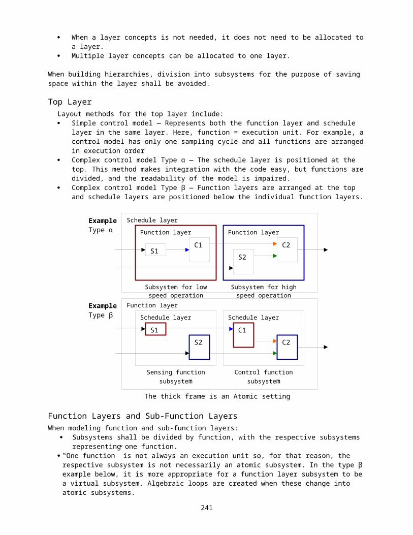
out2= temp1 + in3 + in4
101
2
3
4
10
1
2
3
4
z1
Unit Delay
z1
Unit Delay1
in1
in2
in3
in4
temp1
temp2
out1
out2
temp1
in5
in4
in2
out2
in1out1
temp2
in6
in3
Atomic SubsystemAn atomic subsystem is detached from the external system and is not subject to cross-border
optimization. Atomic subsystems do not use the results of the internal calculations of each subsystem. Therefore, interim output value will use a calculation result that is delayed by a session.temp1= in1 + in2temp2= in4 + in5out1= in1+ in2 + in3out2= in4+ in5 + in6in3= temp2in6= temp1
Atomic subsystems prohibit the direct referencing of the interim calculation results to other subsystems.
101
2
3
4
10
1
2
3
4
z1
Unit Delay
z1
Unit Delay1
in1
in2
in3
in4
temp1
temp2
out1
out2
temp1
in5
in4
in2
out2
in1out1
temp2
in6
in3
Notes on atomic subsystems Atomic subsystems can select C-source function settings. As explained above, the internal section of an atomic subsystem will become encapsulated
(objectified).
Atomic subsystem
Cross-referencing is not possible, so delays need to be inserted on the lines connecting subsystems.
With virtual subsystem, it is possible to consult the values within other subsystems.
Virtual subsystem
Since mutual consultation is possible, no delay occurs even when it is turned into a subsystem
241
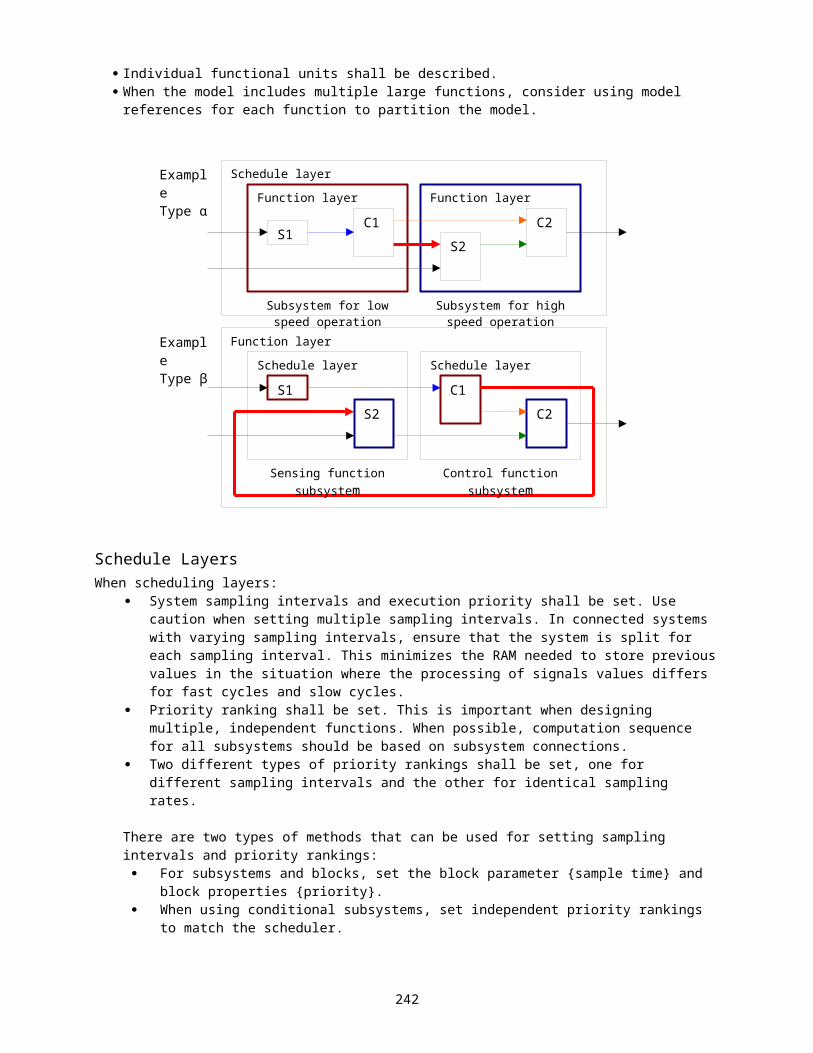
Depending on the relationship before and after, a static RAM section should be secured inside the subsystem for the output signal.
Atomic subsystems (including the addition of function settings) should be used with caution. Factor setting will not simply have a factor name inserted within a C code. It should be acknowledged that it is described as a mathematically independent system and the conditions under which an atomic subsystem can be used should be reviewed.
Include the relationship with the structure layer; it is necessary to determine an operation rule per project and to determine its relationship with the guideline rules.
9.5. Modeling Knowledge / Usage Patterns
Appendix 1: Simulink Patterns for If, elseif, else ConstructsThese patterns shall be used for if, elseif, else constructs.
Function Simulink pattern[Switch] is used. If, elseif, else construct
if (If_Condition){output_signal = If_Value;
}else if (Else_If_Condition){output_signal = Else_If_Value;
}else{output_signal = Else_Value;
}If, elseif, else construct using Action Subsystem
if (Fault_1_Active & Fault_2_Active){ErrMsg = SaftyCrit;
}else if (Fault_1_Active | Fault_2_Active){ErrMsg = DriverWarn;
}else{ErrMsg = NoFaults;
}
Appendix 2: Simulink Patterns for Case ConstructsThese patterns shall be used for case constructs.
Function Simulink patternCase construct using if Action Subsystem
switch (PRNDL_Enum){case 1
242
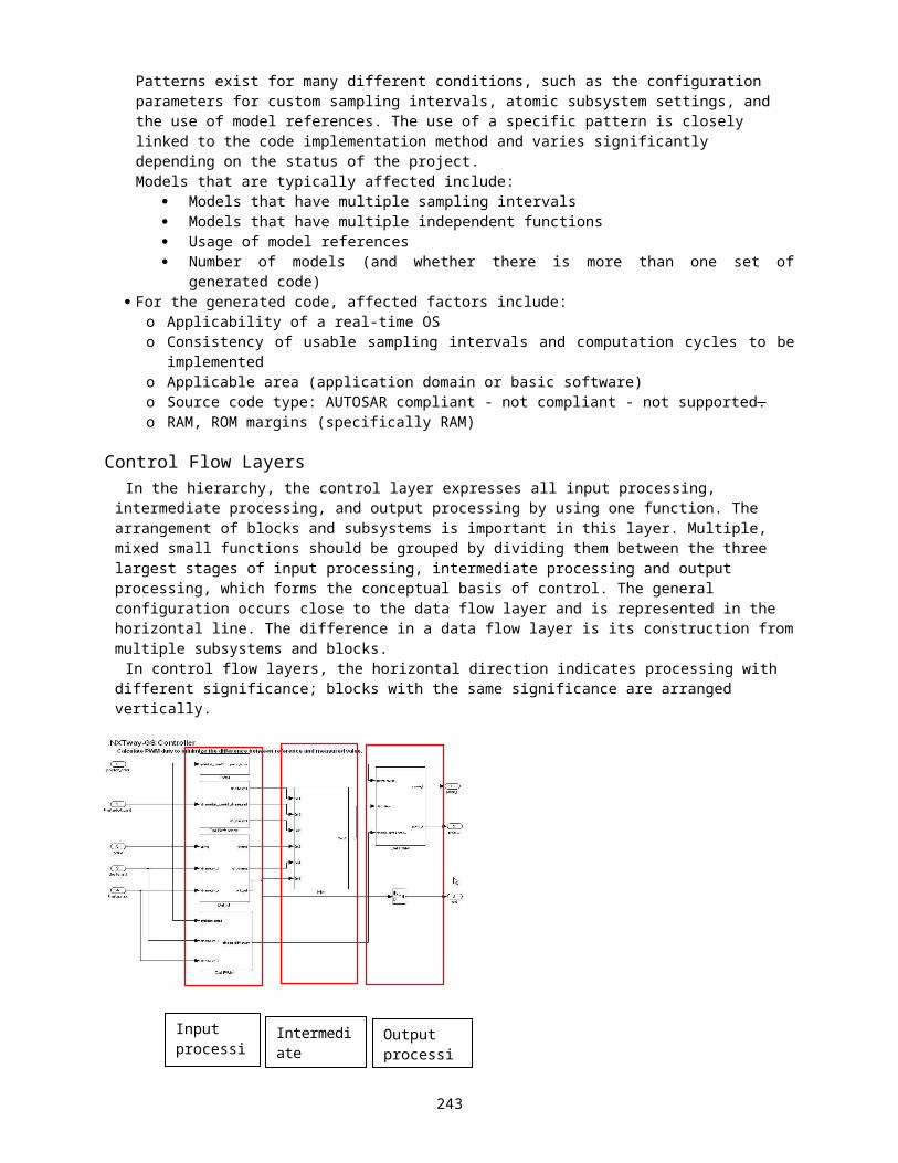
TqEstimate = ParkV;break;
case 2TqEstimate = RevV;break;
default TqEstimate = NeutralV;break;
}
Case construct using Multiport Switch
switch (Selection){case 1:output_signal =look1_binlxpw(In2,y1,x1,3U);
break;case 2:output_signal =look1_binlxpw(In3,y2,x2,3U);
break;case 3:output_signal =look1_binlxpw(In4,y3,x3,3U);
break;default:output_signal =look1_binlxpw(In5,y4,x4,3U);
break;}
Appendix 3: Simulink Patterns for Logical ConstructsThese patterns shall be used for Simulink logical constructs.
Conjunctive normal form
243
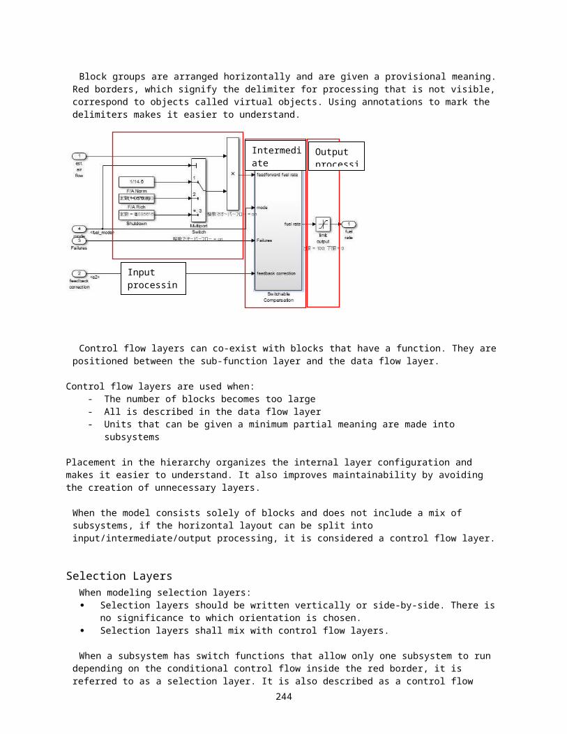
Disjunctive normal form
Appendix 4: Simulink Patterns for Vector SignalsThese patterns shall be used for vector signals.
Function Simulink patternVector signal and parameter (scalar) multiplicationfor (i=0; i>input_vector_size; i++) {output_vector[i] = input_vector[i] *tunable_parameter_value;
}
(Reference: generated code of R2013b)for (i = 0; i < input_vectorDim; i++) {
244
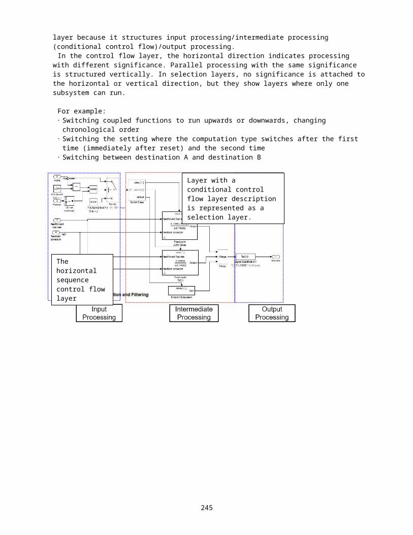
output_vector[i] =tunable_parameter_value *input_vector[i];
}
(As the code is generated using a variable number of dimensions, the upper limit of the normal loop is a direct value.)Multiplication of vector signals and parameters (vectors)
for (i=0; i>input_vector_size; i++) {output_vector[i] = input_vector[i] *tunable_parameter_vector[i];
}Vector signal element multiplication
output_signal = 1;for (i=0; i>input_vector_size; i++) {output_signal = output_signal *input_vector[i];
}Vector signal element division
output_signal = 1;for (i=0; i>input_vector_size; i++) {output_signal = output_signal /input_vector[i];
}Vector signal and parameter (scalar) addition
for (i=0; i>input_vector_size; i++) {output_vector[i] = input_vector[i] +tunable_parameter_value;
}Vector signal and parameter (vector) addition
for (i=0; i>input_vector_size; i++) {output_vector[i] = input_vector[i] +tunable_parameter_vector[i];
}Vector signal and parameter (vector) addition
for (i=0; i>input_vector_size; i++) {output_vector[i] = input_vector[i] +tunable_parameter_vector[i];
}Vector signal element subtraction
output_signal = 0;for (i=0; i>input_vector_size; i++) {output_signal = output_signal –input_vector[i];
}
245
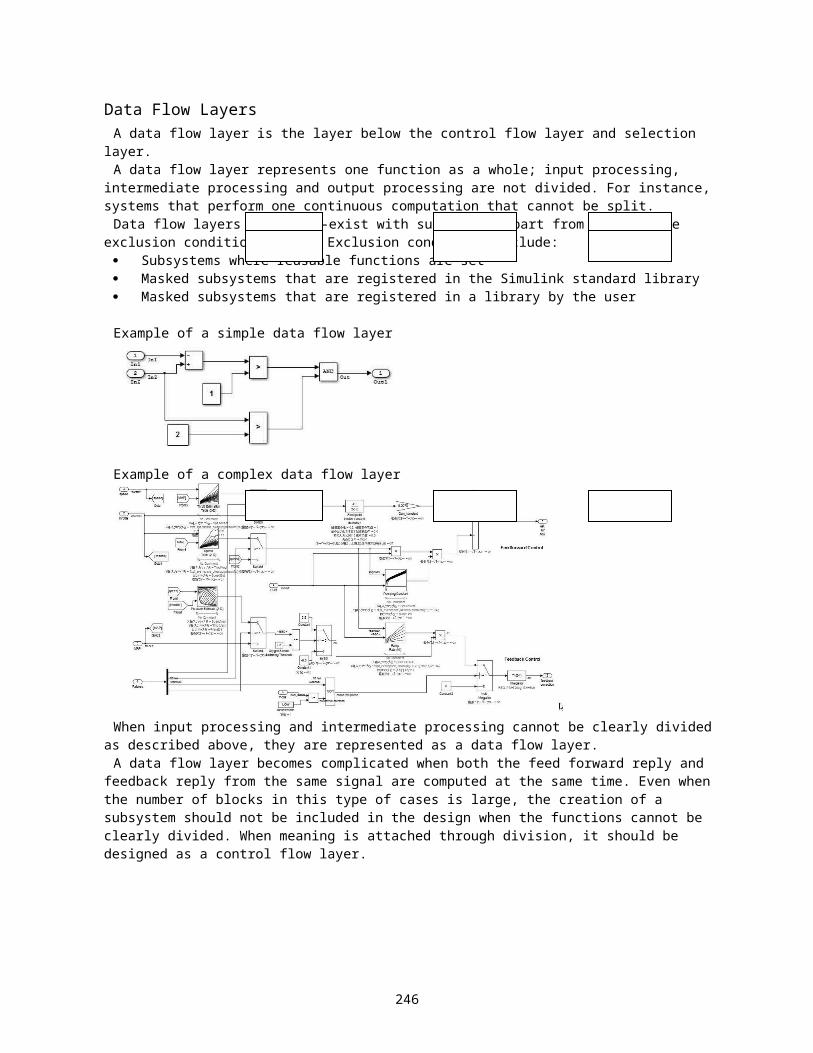
Retention of minimum value/maximum value
Appendix 5: Using Switch and if-then-else Action Subsystems [Switch] shall be used for modeling simple if, elseif, else structures when the associated elseif and else
actions involve only the assignment of constant values.
Recommended: For a simple if, elseif, else structure, use [Switch].
Not recommended: Using [If], [If Action Subsystem] for a simple if, elseif, else structure.
Recommended: For a complex if, elseif, else structure, use [If], [If Action Subsystem].
246
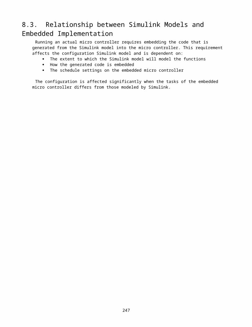
Not recommended: Using [Switch] for a complex if, elseif, else structure.
Appendix 6: Use of if, elseif, else Action Subsystem to Replace Multiple SwitchesFrequent use of [Switch] for condition bifurcation shall be avoided. Instead, the {upper limit target} shall be used (such as up to three levels). When the target value is exceeded, a conditional control flow using the if, elseif, else Action Subsystem shall be used.
Not recommended: Four levels of nesting.
247
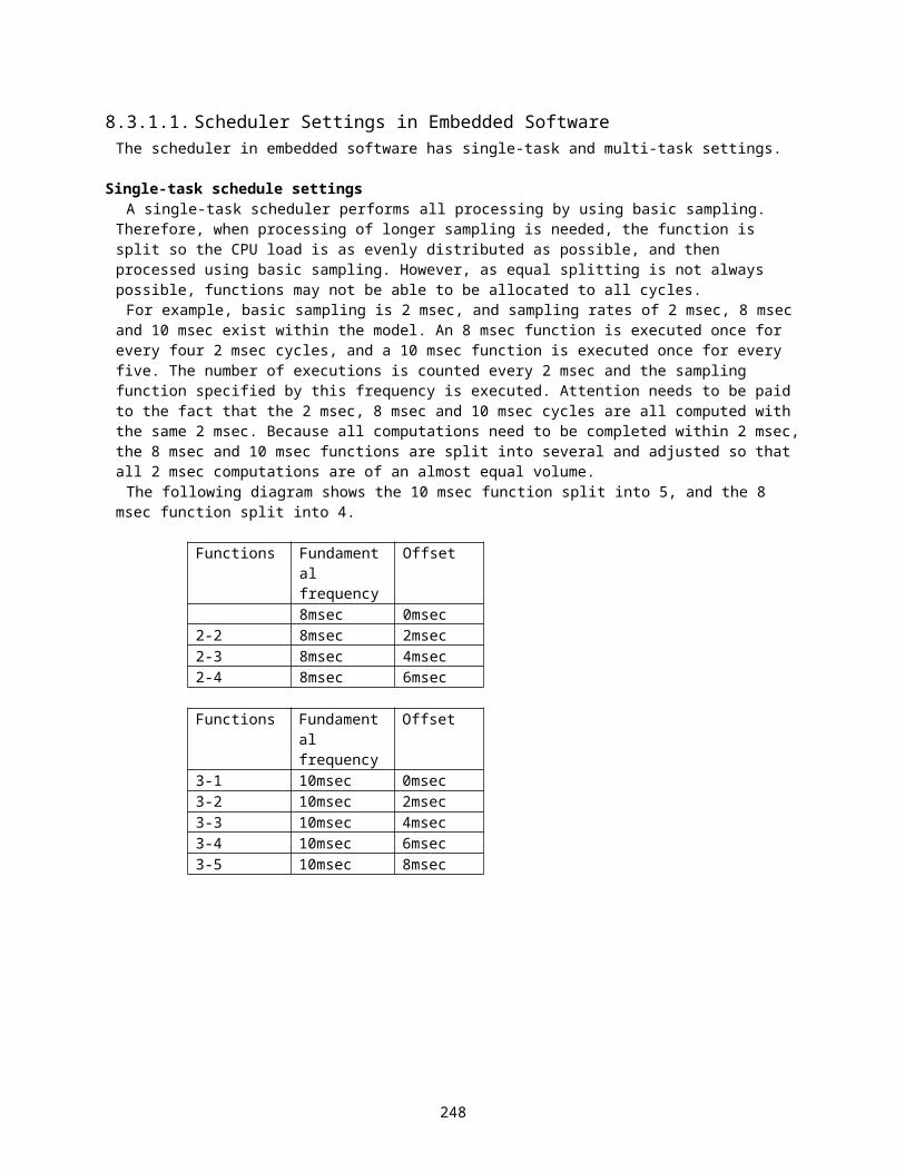
Recommended: By setting the fourth level as an if Action subsystem, nesting is limited to a single level.
248
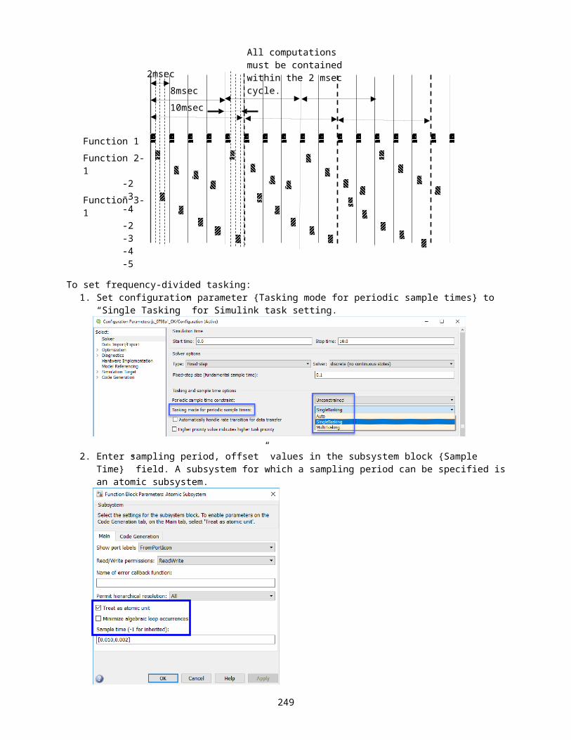
Not recommended: Not dividing by using an if Action subsystem.
Use atomic subsystem + function setting when the C code limit is applied. In this case, there is no need to use the if, elseif, else Action Subsystem, but the configuration of [Switch] can be split and encapsulated in the subsystem.
Example of model with five levels of nesting.
Not recommended:
1In1
1Out12
In2
3In3
4In4
5In5
~= 0
Switch
[In1]
Goto1
[In2]
Goto2
[In3]
Goto3
[In4]
Goto4
[In5]
Goto5
[In1]
From
~= 0
Switch1
[In1]
From1
~= 0
Switch2
[In1]
From2
~= 0
Switch3
[In1]
From3
~= 0
Switch4
[In1]
From4
1
Constant
2
Constant1
3
Constant2
4
Constant3
5
Constant4
6
Constant5
249
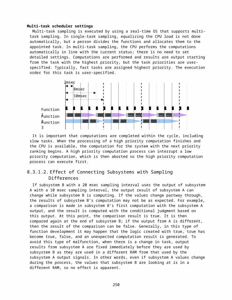
Recommended: Use a description method that avoids layering of [Switch] nesting
1In1
1Out1
2In2
3In3
4In4
5In5
1
Constant
u1if(u1 ~= 0)
else
If if { }In1 Out1
If ActionSubsystem
else { }
In1
In2
In3
In4
Out1
If ActionSubsystem1
Merge
1Out1
else { }
Action Port = held状態 = 1/2階層数
1In1
2
Constant1
u1if(u1 ~= 0)
else
If ActionIn1 Out1
If ActionSubsystem
else { }
In2
In3
In1
Out1
If ActionSubsystem1
2In2
3In3
Merge
4In4
While provided as an example, If Action Subsystem a are not typically used for switching the fixed value. In these Recommended and Not Recommended examples, the generated C code will be the same if the user does not add a function conversion setting. (Confirmed in R2010b to R2013a) The C code is unconstrained.
250
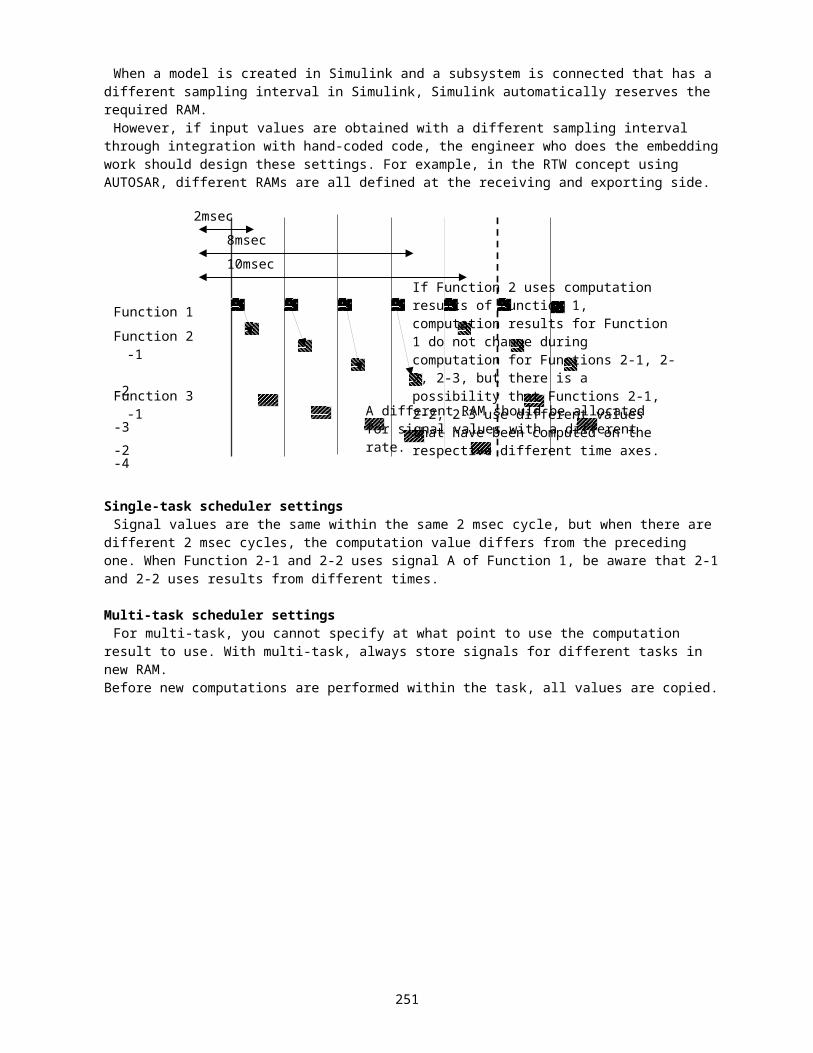
Appendix 7: Usage Rules for Action Subsystems Using Conditional Control FlowAn If Action subsystem shall not be used when the associated actions do not have a status variable.
Recommended
if { }In1
In4
In5
Out1
If Action Subsystem
u1if(u1 ~= 0)
else
If
else { }In1
In2
Out1
If Action Subsystem1
Merge
1In1
2In2
3In3
4In4
1Out1
Example of model with 5 levels of nesting
RecommendedLayering by using a subsystem does not occur because there is no internal state.
1In1
1Out1
2In2
3In3
4In4
5In5
~= 0
Switch
[In1]
Goto1
[In2]
Goto2
[In3]
Goto3
[In4]
Goto4
[In5]
Goto5
[In1]
From
~= 0
Switch1
[In1]
From1
~= 0
Switch2
[In1]
From2
~= 0
Switch3
[In1]
From3
~= 0
Switch4
[In1]
From4
1
Constant
2
Constant1
3
Constant2
4
Constant3
5
Constant4
6
Constant5
251
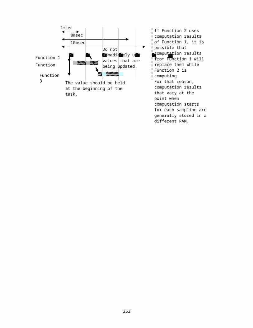
RecommendedAn atomic subsystem is used to split either side of [Switch] without using an Action subsystem.
252
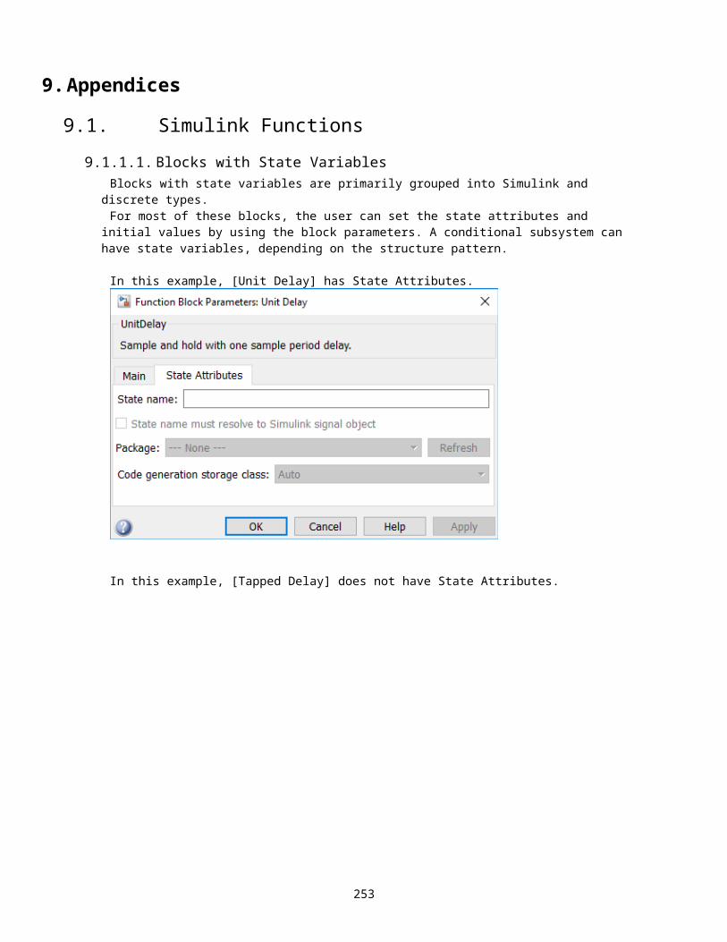
Not recommended:Layering through the use of an unnecessary Action subsystem.
1In1
1Out1
2In2
3In3
4In4
5In5
1
Constant
u1if(u1 ~= 0)
else
If if { }In1 Out1
If ActionSubsystem
else { }
In1
In2
In3
In4
Out1
If ActionSubsystem1
Merge
1Out1
else { }
Action Port = held状態 = 1/2階層数
1In1
2
Constant1
u1if(u1 ~= 0)
else
If ActionIn1 Out1
If ActionSubsystem
else { }
In2
In3
In1
Out1
If ActionSubsystem1
2In2
3In3
Merge
4In4
If a function can be achieved by using the Action subsystem, then layering using the Action subsystem is not performed.In the Not Recommended example, when the lowest level [Unit Delay] on the third level is initialized, the conditional subsystem initialization is first executed one time on the upper first level, and then again on the second level for a total of two times of initial value settings. To prevent the generation of unnecessary code, it is recommended that listing not be made in conditional subsystems that reside in levels where the state variable does not exist.
Since there is no block that has a state variable in this level, there is no need to use the Action subsystem.
This state variable is initialized at the same time as the initialization of the upper layer and executed several times in the same cycle.While there is no problem with the calculation result,wasteful processes are performed.
253
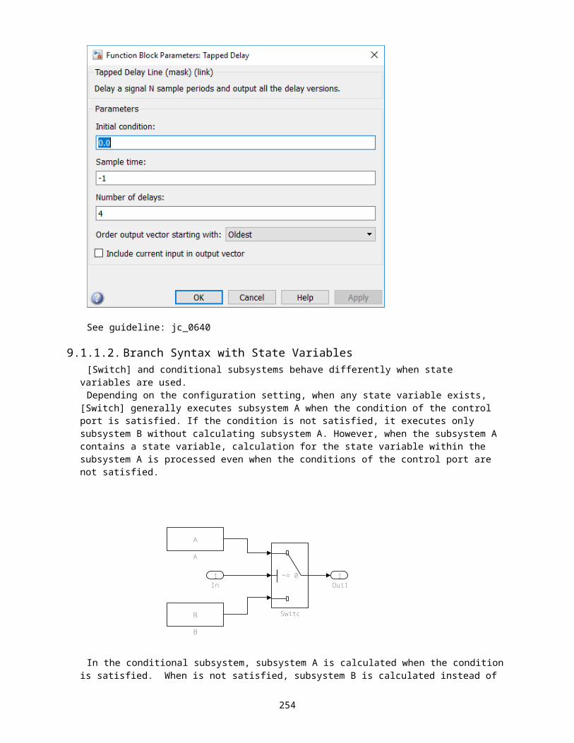
This is based on the concept that the model complexity is reduced by dropping to a level. The purpose of the rule is to avoid the execution of unnecessary initializations.For bifurcation of systems where the bifurcation condition nest has a deep structure, split by using function conversions to decrease the code bifurcation nesting. Functions before and after [Switch] are divided into respective subsystems, and function settings are applied to the atomic subsystem+function. Be aware, it is possible that this may result in unintentional implementation and unnecessary RAM requirements.
Appendix 8: Tests for Information From ErrorsWhen functions that are used in Stateflow (graphical functions, MATLAB functions, etc.) results in an error, the error information shall be transformed into a model structure that will facilitate testing.Not reviewing the error information returned by the functions can result in unintended behavior.
Recommended Error information is incorporated into the model structure, allowing the user to review and respond to the errors.
Not recommended:Error information is not incorporated into the model structure.
254
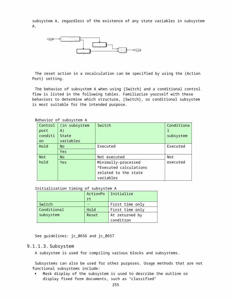
Appendix 9: Flow Chart Patterns for Conditions
These patterns shall be used for conditions within Stateflow flow charts.
Equivalent Functionality Flow Chart Pattern
ONE CONDITION:
[condition]
UP TO THREE CONDITIONS, SHORT FORM: (The use of different logical operators in this form is not allowed. Use sub conditions instead.)
[condition1 && condition2 && condition3] [condition1 || condition2 || condition3]
TWO OR MORE CONDITIONS, MULTILINE FORM: (The use of different logical operators in this form is not allowed. Use sub conditions instead.)
[condition1 ...&& condition2 ... && condition3] [condition1 ...|| condition2 ...|| condition3]
255
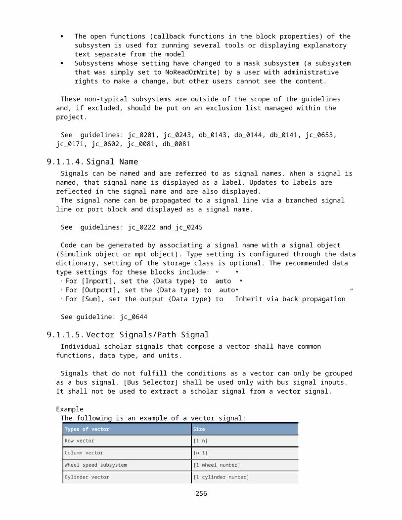
CONDITIONS WITH SUBCONDITIONS: (The use of different logical operators to connect sub conditions is not allowed. The use of brackets is mandatory.)
[(condition1a || condition1b) ... && (condition2a || condition2b) ... && (condition3)] [(condition1a && condition1b) ... || (condition2a && condition2b) ... || (condition3)]
CONDITIONS THAT ARE VISUALLY SEPARATED: (This form can be combined with the preceding patterns.)
[condition1 && condition2] [condition1 || condition2]
Appendix 10: Flow Chart Patterns for Condition Actions
These patterns shall be used for condition actions within Stateflow flow charts.
Equivalent Functionality Flow Chart Pattern
ONE CONDITION ACTION: action;
TWO OR MORE CONDITION ACTIONS, MULTILINE FORM: (Two or more condition actions in one line are not allowed.) action1; ... action2; ... action3; ...
256
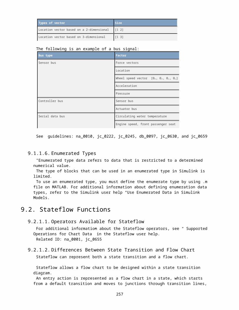
CONDITION ACTIONS, WHICH ARE VISUALLY SEPARATED: (This form can be combined with the preceding patterns.) action1a; action1b; action2; action3;
Appendix 11: Flow Chart Patterns for if Constructs
These patterns shall be used for If constructs within Stateflow flow charts.
Function Flow Chart Pattern
If construct
if (condition){action;
}
If, else construct
if (condition) {action1;
}else {action2;
}
257
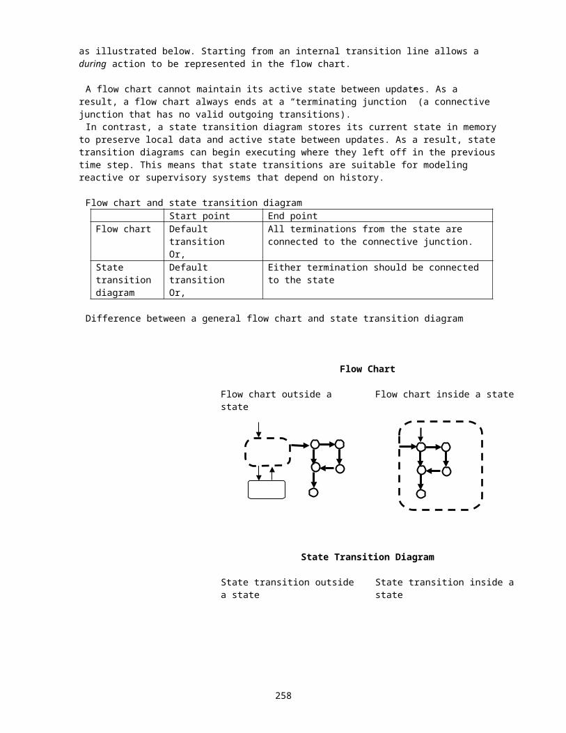
If, elseif, else construct
if (condition1) {action1;
}else if (condition2) {action2;
}else if (condition3) {action3;
}else {action4;
}
Cascade of if construct
if (condition1) {action1;if (condition2) {action2;if (condition3) {action3;
}}
}
258
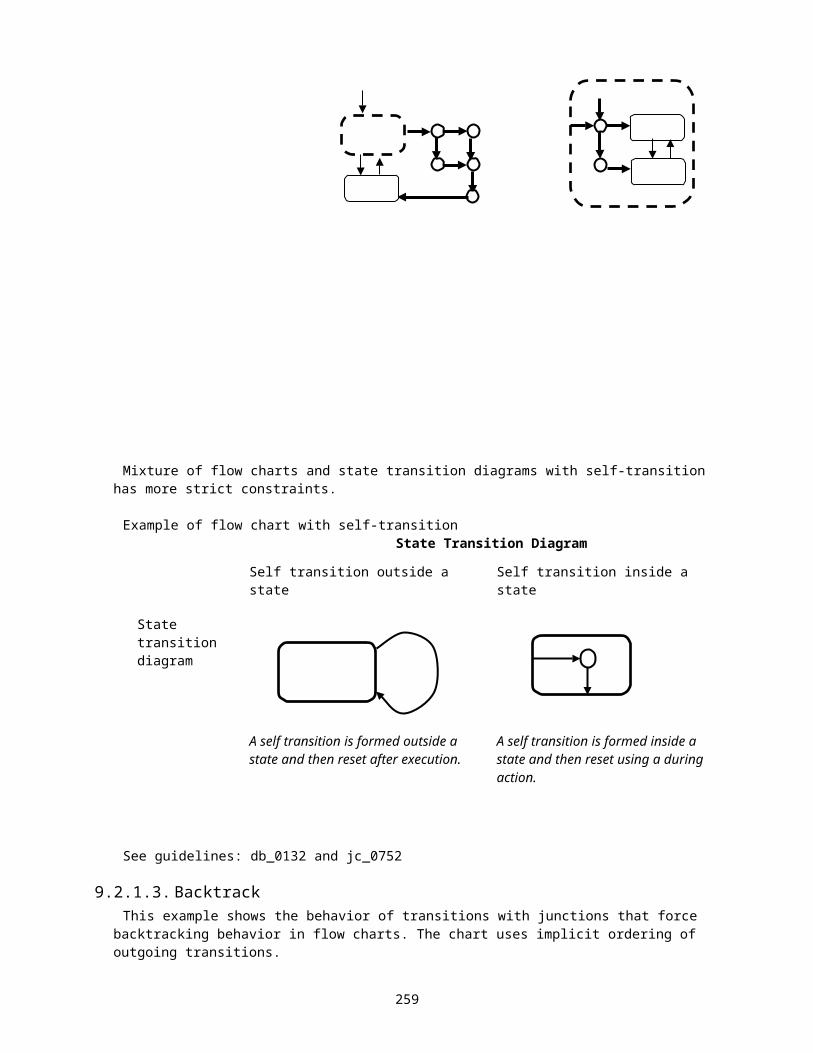
Appendix 12: Flow Chart Patterns for Case ConstructsThese patterns shall be used for case constructs in Stateflow flow charts.
Function Simulink pattern
Case construct with exclusive selection selection = u1;switch (selection) {case 1: y1 = 1; break;
case 2:y1 = 2;break;
case 3:y1 = 4;break;
default: y1 = 8;
}
{y1 = 4;}
{y1 = 8;}
2
[selection == 3]1
{y1 = 2;}
[selection == 2]1
2
[selection == 1]1
{selection = u1;}
2
{y1 = 1;}
Case construct with exclusive conditions
c1 = u1;c2 = u2;c3 = u3;if (c1 && ! c2 && ! c3) {y1 = 1;
}elseif (! c1 && c2 && ! c3) {y1 = 2;
}elseif (! c1 && ! c2 && c3) {y1 = 4;
}else {y1 = 8;
}
[!c1 && !c2 && c3]1
2
2
[!c1 && c2 && !c3]1
[c1 && !c2 && !c3]1
{y1 = 8;}
2
{y1 = 1;}
{y1 = 4;}
{c1 = u1;c2 = u2;c3 = u3;}
{y1 = 2;}
Appendix 13: Flow Chart Patterns for Loop ConstructsThese patterns shall be used to create loop constructs in Stateflow flow charts.
Function Flow Chart PatternFor loop construct
for ( index = 0;index < number_of_loops;index++ )
259
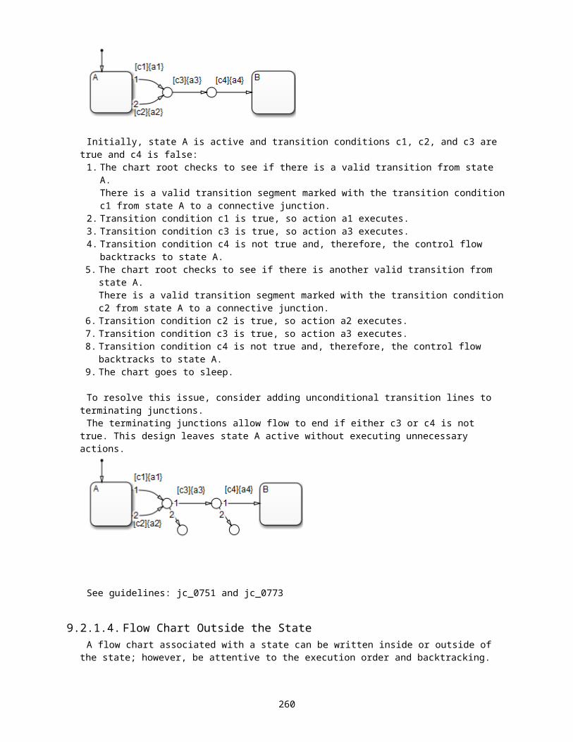
{action;
}
While loop construct
while ( condition ){action;
}
Do while loop construct
do{action;
}while ( condition )
260
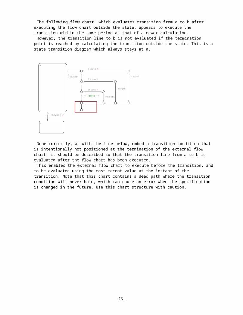
Appendix 14: State Machine Patterns for Conditions
These patterns shall be used for conditions within Stateflow state machines.
Equivalent Functionality State Machine Pattern
ONE CONDITION:
(condition)
UP TO THREE CONDITIONS, SHORT FORM: (The use of different logical operators in this form is not allowed, use sub conditions instead)
(condition1 && condition2) (condition1 || condition2)
TWO OR MORE CONDITIONS, MULTILINE FORM: A sub condition is a set of logical operations, all of the same type, enclosed in parentheses.(The use of different operators in this form is not allowed, use sub conditions instead.)
(condition1 ... && condition2 ... && condition3)
(condition1 ...|| condition2 ...|| condition3)
Appendix 15: State Machine Patterns for Transition Actions
These patterns shall be used for transition actions within Stateflow state machines.
Equivalent Functionality State Machine Pattern
ONE TRANSITION ACTION:
action;
TWO OR MORE TRANSITION ACTIONS, MULTILINE FORM: (Two or more transition actions in one line are not allowed.)
action1; action2; action3;
261
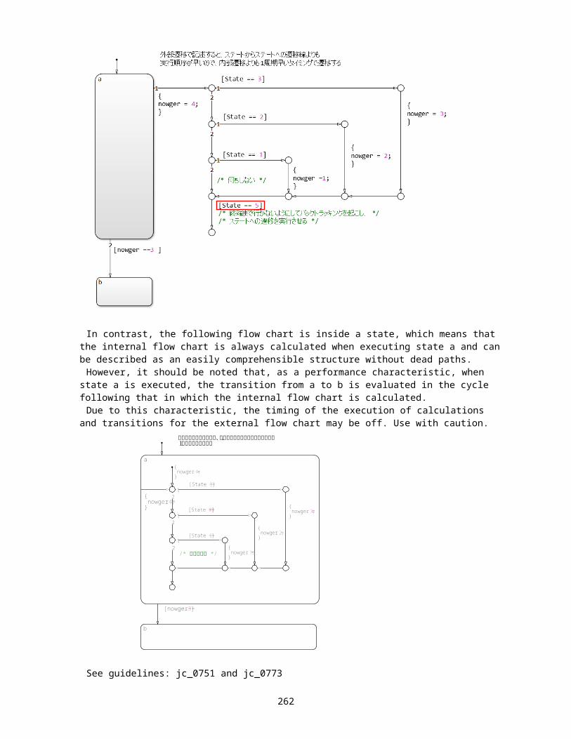
Appendix 16: Limiting State Layering
Within a single viewer (subviewer), multiple layering shall be limited by defining constraints for a single view (subview). Subcharts shall be used to switch the screen when defined constraint goals are exceeded.
RecommendedThe fourth level is encapsulated in a subchart.
Not recommended:The constraint goal is set to three levels, but Level_4_a and Level_4_b have more than three levels and are nested.
Appendix 17: Number of States per Stateflow ContainerThe number of states per Stateflow container shall be determined by the number of states that can be viewed in the diagram. All states should be visible and readable.
262

Appendix 18: Function Call from StateflowIf a state exists in the Function Call Subsystem of the call target, and a “reset” of the state is required when the state of the caller becomes inactive, the caller shall use a bind action.
Appendix 19: Function Types Available in StateflowThe functions types used in Stateflow shall be dependent on the required processing.
For graphical functions, use:o If, elseif, else logic
For Simulink functions, use:o Transfer functionso Integratorso Table look-ups
For MATLAB functions, use:o Complex equationso If, elseif, else logic
263