Embed Size (px)
Citation preview
1
CONTROL ALGORITHM MODELING GUIDELINES USING MATLAB®,
Simulink®, and Stateflow® Version 2.0
MathWorks Automotive Advisory Board
(MAAB) July 27th, 2007
2
CONTROL ALGORITHM MODELING GUIDELINES USING MATLAB®, SIMULINK®, AND STATEFLOW®............................................................................................................................................. 1 1. HISTORY.................................................................................................................................................. 5 2. INTRODUCTION .................................................................................................................................... 6
2.1. MOTIVATION ........................................................................................................................................ 6 2.1.1. Guideline template........................................................................................................................ 6 2.1.2. Guideline ID:................................................................................................................................ 6 2.1.3. Guideline Title:............................................................................................................................. 7 2.1.4. Priority: ........................................................................................................................................ 7 2.1.5. Scope: ........................................................................................................................................... 8 2.1.6. MATLAB® Versions ...................................................................................................................... 8 2.1.7. Prerequisites: ............................................................................................................................... 8 2.1.8. Description:.................................................................................................................................. 8 2.1.9. Rationale: ..................................................................................................................................... 8 2.1.10. Last change: ............................................................................................................................... 9
2.2. DOCUMENT USAGE............................................................................................................................... 9 2.2.1. Guideline Interaction Semantics................................................................................................... 9
3. NAMING CONVENTIONS .................................................................................................................. 10 3.1. GENERAL GUIDELINES ....................................................................................................................... 10
3.1.1. ar_0001: Filenames.................................................................................................................... 10 3.1.2. ar_0002: Directory names.......................................................................................................... 10
3.2. MODEL CONTENT GUIDELINES........................................................................................................... 11 3.2.1. jc_0201: Usable characters for Subsystem name....................................................................... 11 3.2.2. jc_0211: Usable characters for Inport block and Outport block ............................................... 12 3.2.3. jc_0221: Usable characters for signal line name....................................................................... 12 3.2.4. jc_0231: Usable characters for block names ............................................................................. 13 3.2.5. na_0014: Use of local language in Simulink and Stateflow ....................................................... 13
4. MODEL ARCHITECTURE ................................................................................................................. 16 4.1. SIMULINK® AND STATEFLOW® PARTITIONING.................................................................................... 16
4.1.1. na_0006: Guidelines for mixed use of Simulink and Stateflow................................................... 16 4.1.2. na_0007: Guidelines for use of Flow Charts, Truth Tables and State Machines ....................... 22
4.2. SUBSYSTEM HIERARCHIES.................................................................................................................. 22 4.2.1. db_0143: Similar block types on the model levels...................................................................... 22 4.2.2. db_0144: Use of Subsystems ...................................................................................................... 23 4.2.3. db_0040: Model hierarchy ......................................................................................................... 24
4.3. J-MAAB MODEL ARCHITECTURE DECOMPOSITION........................................................................... 24 4.3.1. jc_0301: Controller model ......................................................................................................... 24 4.3.2. jc_0311: Top layer / root level ................................................................................................... 25 4.3.3. jc_0321: Trigger layer................................................................................................................ 26 4.3.4. jc_0331: Structure layer ............................................................................................................. 26 4.3.5. jc_0341: Data flow layer ............................................................................................................ 27
5. MODEL CONFIGURATION OPTIONS ............................................................................................ 29 5.1.1. jc_0011: Optimization parameters for Boolean data types ........................................................ 29 5.1.2. jc_0021: Model diagnostic settings ............................................................................................ 29
6. SIMULINK ............................................................................................................................................. 31 6.1. DIAGRAM APPEARANCE ..................................................................................................................... 31
6.1.1. na_0004: Simulink model appearance ....................................................................................... 31 6.1.2. db_0043: Simulink font and font size.......................................................................................... 32 6.1.3. db_0042: Port block in Simulink models .................................................................................... 33
3
6.1.4. na_0005: Port block name visibility in Simulink models............................................................ 34 6.1.5. jc_0081: Icon display for Port block .......................................................................................... 34 6.1.6. jm_0002: Block resizing ............................................................................................................. 35 6.1.7. db_0142: Position of block names.............................................................................................. 36 6.1.8. jc_0061: Display of block names................................................................................................ 36 6.1.9. db_0146: Triggered, enabled, conditional Subsystems .............................................................. 37 6.1.10. db_0140: Display of basic block parameters ........................................................................... 38 6.1.11. jm_0013: Annotations............................................................................................................... 39 6.1.12. db_0032: Simulink signal appearance ..................................................................................... 39 6.1.13. db_0141: Signal flow in Simulink models................................................................................. 40 6.1.14. jc_0171: Maintaining signal flow when using Goto and From blocks ..................................... 41 6.1.15. jm_0010: Port block names in Simulink models....................................................................... 42 6.1.16. jc_0281: Naming of Trigger Port block and Enable Port block............................................... 42
6.2. SIGNALS ............................................................................................................................................. 43 6.2.1. na_0008: Display of labels on signals........................................................................................ 43 6.2.2. na_0009: Entry versus propagation of signal labels .................................................................. 44 6.2.3. db_0097: Position of labels for signals and busses.................................................................... 45 6.2.4. db_0081: Unconnected signals, block inputs and block outputs ................................................ 46
6.3. BLOCK USAGE.................................................................................................................................... 46 6.3.1. na_0003: Simple logical expressions in If Condition block ....................................................... 46 6.3.2. na_0002: Appropriate implementation of fundamental logical and numerical operations........ 48 6.3.3. jm_0001: Prohibited Simulink standard blocks inside controllers............................................. 49 6.3.4. hd_0001: Prohibited Simulink sinks ........................................................................................... 51 6.3.5. na_0011: Scope of Goto and From blocks ................................................................................. 51 6.3.6. jc_0141: Use of the Switch block................................................................................................ 52 6.3.7. jc_0121: Use of the Sum block ................................................................................................... 53 6.3.8. jc_0131: Use of Relational Operator block................................................................................ 54 6.3.9. jc_0161: Use of Data Store Read/Write/Memory blocks............................................................ 55
6.4. BLOCK PARAMETERS.......................................................................................................................... 55 6.4.1. db_0112: Indexing...................................................................................................................... 55 6.4.2. na_0010: Grouping data flows into signals............................................................................... 56 6.4.3. db_0110: Tunable parameters in basic blocks ........................................................................... 57
6.5. SIMULINK PATTERNS.......................................................................................................................... 58 6.5.1. na_0012: Use of Switch vs. If-Then-Else Action Subsystem....................................................... 58 6.5.2. db_0114: Simulink patterns for If-then-else-if constructs .......................................................... 59 6.5.3. db_0115: Simulink patterns for case constructs......................................................................... 60 6.5.4. db_0116: Simulink patterns for logical constructs with logical blocks ...................................... 62 6.5.5. db_0117: Simulink patterns for vector signals ........................................................................... 62 6.5.6. jc_0351: Methods of initialization.............................................................................................. 64 6.5.7. jc_0111: Direction of Subsystem ................................................................................................ 65
7. STATEFLOW......................................................................................................................................... 67 7.1. CHART APPEARANCE.......................................................................................................................... 67
7.1.1. db_0123: Stateflow port names .................................................................................................. 67 7.1.2. db_0129: Stateflow transition appearance................................................................................. 67 7.1.3. db_0137: States in state machines.............................................................................................. 68 7.1.4. db_0133: Use of patterns for Flowcharts................................................................................... 69 7.1.5. db_0132: Transitions in Flowcharts........................................................................................... 69 7.1.6. jc_0501: Format of entries in a State block................................................................................ 71 7.1.7. jc_0511: Setting the return value from a graphical function...................................................... 72 7.1.8. jc_0531: Placement of the default transition.............................................................................. 73 7.1.9. jc_0521: Use of the return value from graphical functions........................................................ 74
7.2. STATEFLOW DATA AND OPERATIONS .................................................................................................. 75 7.2.1. na_0001: Bitwise Stateflow operators........................................................................................ 75 7.2.2. jc_0451: Use of unary minus on unsigned integers in Stateflow................................................ 76 7.2.3. na_0013: Comparison operation in Stateflow............................................................................ 76
4
7.2.4. db_0122: Stateflow and Simulink interface signals and parameters.......................................... 77 7.2.5. db_0125: Scope of internal signals and local auxiliary variables ............................................. 78 7.2.6. jc_0481: Use of hard equality comparisons for floating point numbers in Stateflow ................ 79 7.2.7. jc_0491: Reuse of variables within a single Stateflow scope ..................................................... 80 7.2.8. jc_0541: Use of tunable parameters in Stateflow....................................................................... 81 7.2.9. db_0127: MATLAB commands in Stateflow............................................................................... 82 7.2.10. jm_0011: Pointers in Stateflow ................................................................................................ 83
7.3. EVENTS .............................................................................................................................................. 83 7.3.1. db_0126: Scope of events ........................................................................................................... 83 7.3.2. jm_0012: Event broadcasts ........................................................................................................ 83
7.4. STATECHART PATTERNS..................................................................................................................... 84 7.4.1. db_0150: State machine patterns for conditions ........................................................................ 84 7.4.2. db_0151: State machine patterns for transition actions............................................................. 85
7.5. FLOWCHART PATTERNS...................................................................................................................... 86 7.5.1. db_0148: Flowchart patterns for conditions .............................................................................. 86 7.5.2. db_0149: Flowchart patterns for condition actions ................................................................... 88 7.5.3. db_0134: Flowchart patterns for If constructs........................................................................... 89 7.5.4. db_0159: Flowchart patterns for case constructs ...................................................................... 91 7.5.5. db_0135: Flowchart patterns for loop constructs ...................................................................... 92
8. APPENDIX A: RECOMMENDATIONS FOR AUTOMATION TOOLS ....................................... 94 9. APPENDIX B: GUIDELINE WRITING ............................................................................................. 95 10. APPENDIX C: FLOWCHART REFERENCE ................................................................................. 96 11. GLOSSARY........................................................................................................................................ 102

5
1.History
Date Change 02.04.2001 Initial document Release, Version 1.00 04.27.2007 Version 2.00 Update release
6
2.Introduction
2.1. Motivation The MAAB guidelines are an important basis for project success and teamwork - both in-house and when cooperating with partners or subcontractors. Respecting the guidelines is one key prerequisite to achieving
• system integration without problems. • well-defined interfaces. • uniform appearance of models, code and documentation. • reusable models. • readable models. • problem-free exchange of models • a simple, effective process • professional documentation. • understandable presentations. • fast software changes. • cooperation with subcontractors. • handing over of (research or predevelopment) projects (to product development)
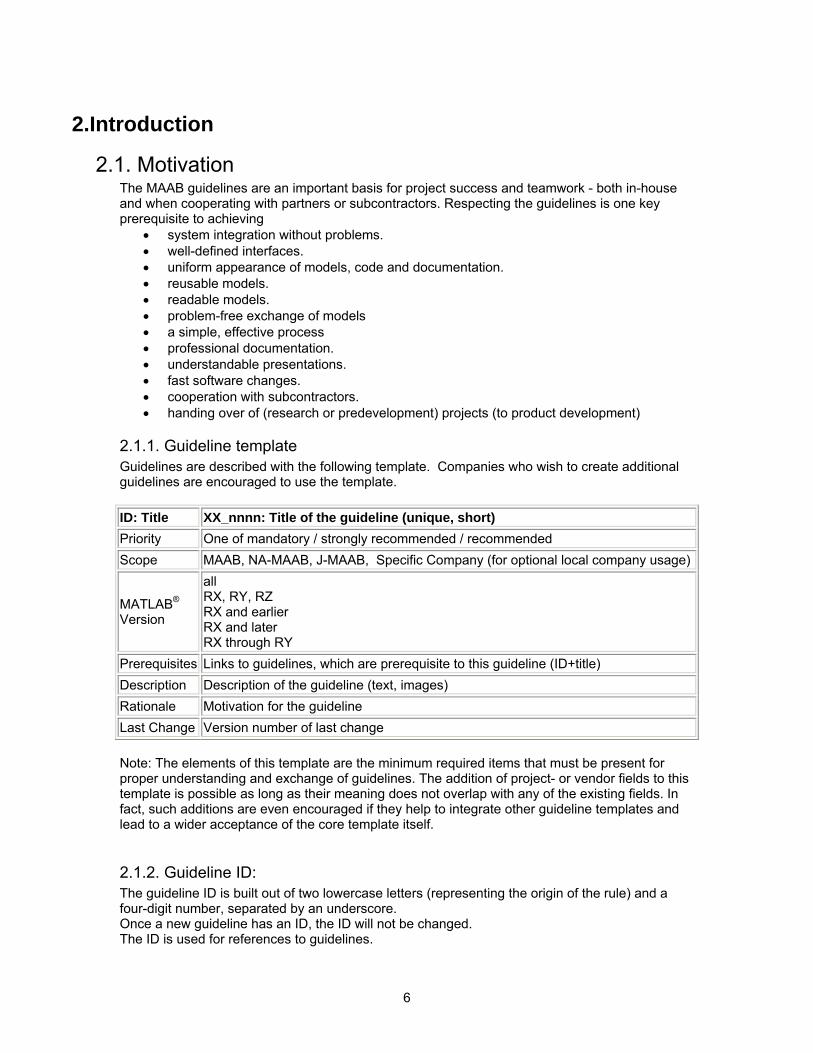
2.1.1. Guideline template Guidelines are described with the following template. Companies who wish to create additional guidelines are encouraged to use the template. ID: Title XX_nnnn: Title of the guideline (unique, short) Priority One of mandatory / strongly recommended / recommended Scope MAAB, NA-MAAB, J-MAAB, Specific Company (for optional local company usage)
MATLAB® Version
all RX, RY, RZ RX and earlier RX and later RX through RY
Prerequisites Links to guidelines, which are prerequisite to this guideline (ID+title) Description Description of the guideline (text, images) Rationale Motivation for the guideline Last Change Version number of last change Note: The elements of this template are the minimum required items that must be present for proper understanding and exchange of guidelines. The addition of project- or vendor fields to this template is possible as long as their meaning does not overlap with any of the existing fields. In fact, such additions are even encouraged if they help to integrate other guideline templates and lead to a wider acceptance of the core template itself.
2.1.2. Guideline ID: The guideline ID is built out of two lowercase letters (representing the origin of the rule) and a four-digit number, separated by an underscore. Once a new guideline has an ID, the ID will not be changed. The ID is used for references to guidelines.
7
The two letter prefixes na, jp, jc and eu are reserved for future MAAB committee rules. Legacy prefixes, db, jm, hd, and ar, are reserved. No new rules will be written with these legacy prefixes.
2.1.3. Guideline Title: The title should be a short, but unique description of the guidelines area of application (e.g., length of names). The title is used for the "prerequisites"-field and for custom checker-tools. There should be a hyperlink with the title-text. It is used for links to the guideline. Note: The title should not be a redundant short description of the guidelines content, because while the latter may change over time, the title should remain stable.
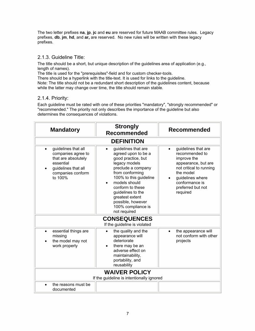
2.1.4. Priority: Each guideline must be rated with one of these priorities "mandatory", "strongly recommended" or "recommended." The priority not only describes the importance of the guideline but also determines the consequences of violations.
Mandatory Strongly Recommended Recommended
DEFINITION • guidelines that all
companies agree to that are absolutely essential
• guidelines that all companies conform to 100%
• guidelines that are agreed upon to be a good practice, but legacy models preclude a company from conforming 100% to this guideline
• models should conform to these guidelines to the greatest extent possible, however 100% compliance is not required
• guidelines that are recommended to improve the appearance, but are not critical to running the model
• guidelines where conformance is preferred but not required
CONSEQUENCES If the guideline is violated
• essential things are missing
• the model may not work properly
• the quality and the appearance will deteriorate
• there may be an adverse effect on maintainability, portability, and reusability
• the appearance will not conform with other projects
WAIVER POLICY If the guideline is intentionally ignored
• the reasons must be documented
8
2.1.5. Scope: The scope can be set to one of the following MAAB (MathWorks Automotive Advisory Board) J-MAAB (Japan MAAB) NA-MAAB (North American MAAB) "MAAB" is a group of automotive manufacturers and suppliers, which work closely together with The MathWorks. MAAB includes the sub-groups J-MAAB, and NA-MAAB. “J-MAAB” is a sub group of MAAB, and is a group of automotive manufacturers and suppliers in JAPAN, which works closely with The MathWorks. Rules with J-MAAB scope are local to Japan. “NA-MAAB” is a sub group of MAAB and is a group of automotive manufacturers and suppliers in USA and Europe, which works closely with The MathWorks. That rule is local rule in USA and Europe. Coverage is USA and Europe.
2.1.6. MATLAB® Versions The guidelines were written to support all versions of MATLAB and Simulink. If the rule applies to a specific version, or versions, it is denoted in this field. The versions information will be one of the following three formats.
• All : all versions of MATLAB • RX, RY, RZ : a specific version of MATLAB • RX and earlier : all versions of MATLAB until version RX • RX and later: all versions of MATLAB from version RX to the current version • RX through RY: all versions of MATLAB between RX and RY
2.1.7. Prerequisites: This field is for links to other guidelines, which are prerequisite to this guideline (logical conjunction). The guideline ID (for consistency) and the title (for readability) have to be used for the links. The "Prerequisites" field should contain no other text.
2.1.8. Description: The "Description" field contains a detailed description of the guideline. If needed, images and tables can be added. Note: If formal notation (math, regular expression, syntax diagrams, and exact numbers/limits) is available, it should be used to unambiguously describe a guideline and specify an automated check. However, a human understandable informal description must always be provided for daily reference.
2.1.9. Rationale: The guidelines can be recommended for one or more of the following reasons.
• Readability: Easily understood algorithms • Readable models • Uniform appearance of models, code, and documentation • Clean interfaces • Professional documentation
• Workflow: Effective Development Process/Workflow • Ease of maintenance • Rapid model changes • Reusable components
9
• Problem-free exchange of models • Model portability
• Simulation: Efficient Simulation and Analysis • Simulation speed • Simulation memory • Model instrumentation
• Verification & Validation • Requirements Traceability • Testing • Problem-free system integration • Clean interfaces
• Code generation: Efficient/effective embedded code generation • Fast software changes • Robustness of generated code
2.1.10. Last change: The “Last Change” field contains the document version number.
2.2. Document Usage The following paragraphs give some directions on how to use this document for reference and for compiling a project-specific guideline document. Information on automated checking of the guidelines can be found in Appendix A.
2.2.1. Guideline Interaction Semantics The initial sections of the document, naming conventions and model architecture are basic guidelines that apply to all types of models. The later sections, Simulink and Stateflow deal with specific rules for those environments. Some guidelines are dependent on other guidelines, these; are explicitly listed throughout the template.
10
3.Naming Conventions
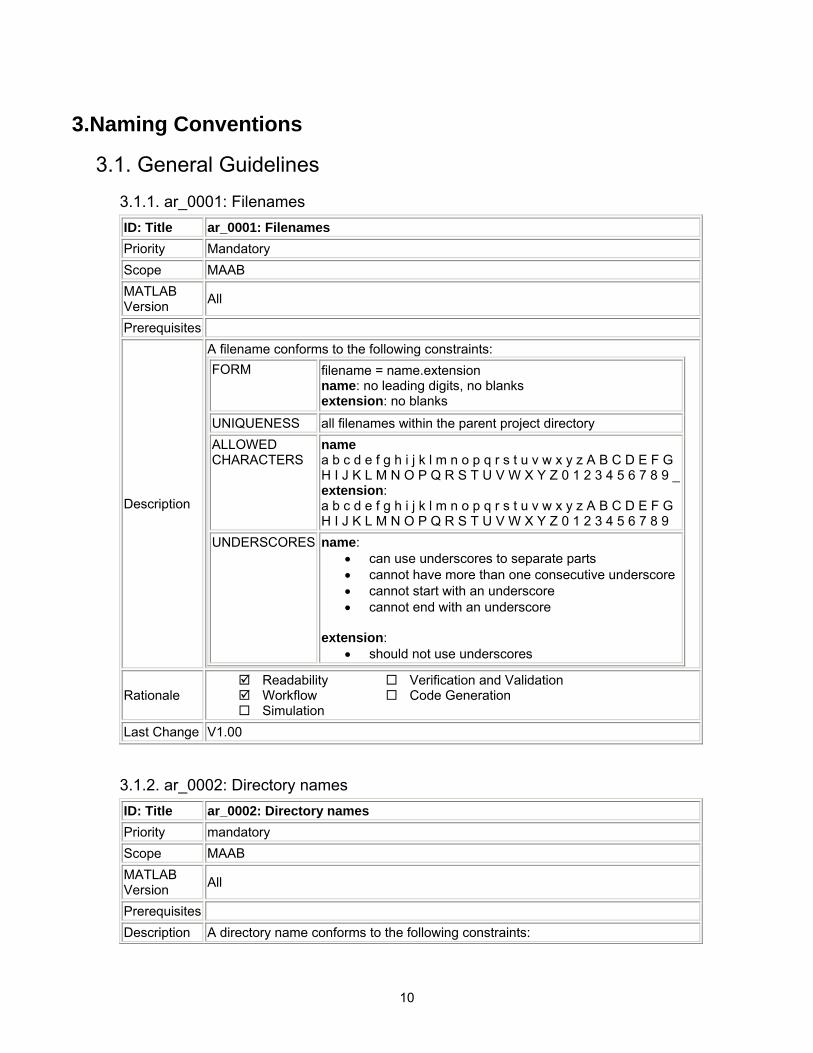
3.1. General Guidelines 3.1.1. ar_0001: Filenames ID: Title ar_0001: Filenames Priority Mandatory Scope MAAB MATLAB Version All
Prerequisites
Description
A filename conforms to the following constraints: FORM filename = name.extension
name: no leading digits, no blanks extension: no blanks
UNIQUENESS all filenames within the parent project directory ALLOWED CHARACTERS
name a b c d e f g h i j k l m n o p q r s t u v w x y z A B C D E F G H I J K L M N O P Q R S T U V W X Y Z 0 1 2 3 4 5 6 7 8 9 _ extension: a b c d e f g h i j k l m n o p q r s t u v w x y z A B C D E F G H I J K L M N O P Q R S T U V W X Y Z 0 1 2 3 4 5 6 7 8 9
UNDERSCORES name: • can use underscores to separate parts • cannot have more than one consecutive underscore • cannot start with an underscore • cannot end with an underscore
extension:
• should not use underscores
Rationale Readability Workflow Simulation
Verification and Validation Code Generation
Last Change V1.00
3.1.2. ar_0002: Directory names ID: Title ar_0002: Directory names Priority mandatory Scope MAAB MATLAB Version All
Prerequisites Description A directory name conforms to the following constraints:
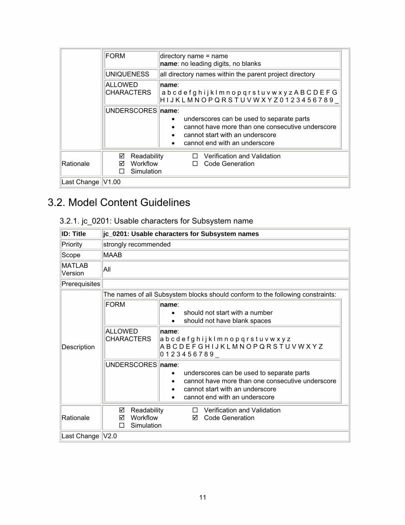
11
FORM directory name = name name: no leading digits, no blanks
UNIQUENESS all directory names within the parent project directory ALLOWED CHARACTERS
name: a b c d e f g h i j k l m n o p q r s t u v w x y z A B C D E F G H I J K L M N O P Q R S T U V W X Y Z 0 1 2 3 4 5 6 7 8 9 _
UNDERSCORES name: • underscores can be used to separate parts • cannot have more than one consecutive underscore • cannot start with an underscore • cannot end with an underscore
Rationale Readability Workflow Simulation
Verification and Validation Code Generation
Last Change V1.00
3.2. Model Content Guidelines 3.2.1. jc_0201: Usable characters for Subsystem name ID: Title jc_0201: Usable characters for Subsystem names Priority strongly recommended Scope MAAB MATLAB Version All
Prerequisites
Description
The names of all Subsystem blocks should conform to the following constraints: FORM name:
• should not start with a number • should not have blank spaces
ALLOWED CHARACTERS
name: a b c d e f g h i j k l m n o p q r s t u v w x y z A B C D E F G H I J K L M N O P Q R S T U V W X Y Z 0 1 2 3 4 5 6 7 8 9 _
UNDERSCORES name: • underscores can be used to separate parts • cannot have more than one consecutive underscore • cannot start with an underscore • cannot end with an underscore
Rationale Readability Workflow Simulation
Verification and Validation Code Generation
Last Change V2.0

12
3.2.2. jc_0211: Usable characters for Inport block and Outport block ID: Title jc_0211: Usable characters for Inport block and Outport block Priority strongly recommended Scope MAAB MATLAB Version All
Prerequisites
Description
The names of all Inport blocks and Outport blocks should conform to the following constraints: FORM name:
• should not start with a number • should not have blank spaces
ALLOWED CHARACTERS
name: a b c d e f g h i j k l m n o p q r s t u v w x y z A B C D E F G H I J K L M N O P Q R S T U V W X Y Z 0 1 2 3 4 5 6 7 8 9 _
UNDERSCORES name: • underscores can be used to separate parts • cannot have more than one consecutive underscore • cannot start with an underscore • cannot end with an underscore
Rationale Readability Workflow Simulation
Verification and Validation Code Generation
Last Change V2.0
3.2.3. jc_0221: Usable characters for signal line name ID: Title jc_0221: Usable characters for signal line names Priority strongly recommended Scope MAAB MATLAB Version All
Prerequisites
Description
All named signals should conform to the following constraints: FORM name:
• should not start with a number • should not have blank spaces • should not have any control characters
ALLOWED CHARACTERS
name: a b c d e f g h i j k l m n o p q r s t u v w x y z A B C D E F G H I J K L M N O P Q R S T U V W X Y Z 0 1 2 3 4 5 6 7 8 9 _
UNDERSCORES name: • underscores can be used to separate parts
13
• cannot have more than one consecutive underscore • cannot start with an underscore • cannot end with an underscore
Rationale Readability Workflow Simulation
Verification and Validation Code Generation
Last Change V2.0
3.2.4. jc_0231: Usable characters for block names ID: Title jc_0231: Usable characters for block names Priority strongly recommended Scope MAAB MATLAB Version All
Prerequisites jc_0201: Usable characters for Subsystem names
Description
All named blocks should conform to the following constraints: FORM name:
• should not start with a number • should not start with a blank space • may not use double byte characters • carriage returns are allowed
ALLOWED CHARACTERS
name: a b c d e f g h i j k l m n o p q r s t u v w x y z A B C D E F G H I J K L M N O P Q R S T U V W X Y Z 0 1 2 3 4 5 6 7 8 9 _
Note: this rule does not apply to Subsystem blocks.
Rationale Readability Workflow Simulation
Verification and Validation Code Generation
Last Change V2.0
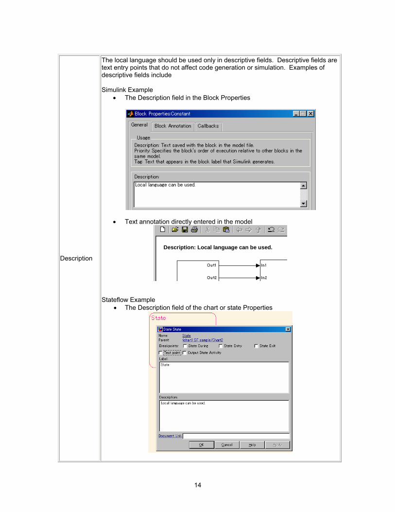
3.2.5. na_0014: Use of local language in Simulink and Stateflow ID: Title na_0014: Use of local language in Simulink and Stateflow Priority strongly recommended Scope J-MAAB MATLAB Version All
Prerequisites
14
Description
The local language should be used only in descriptive fields. Descriptive fields are text entry points that do not affect code generation or simulation. Examples of descriptive fields include Simulink Example
• The Description field in the Block Properties
• Text annotation directly entered in the model
Description: Local language can be used.
Stateflow Example • The Description field of the chart or state Properties
15
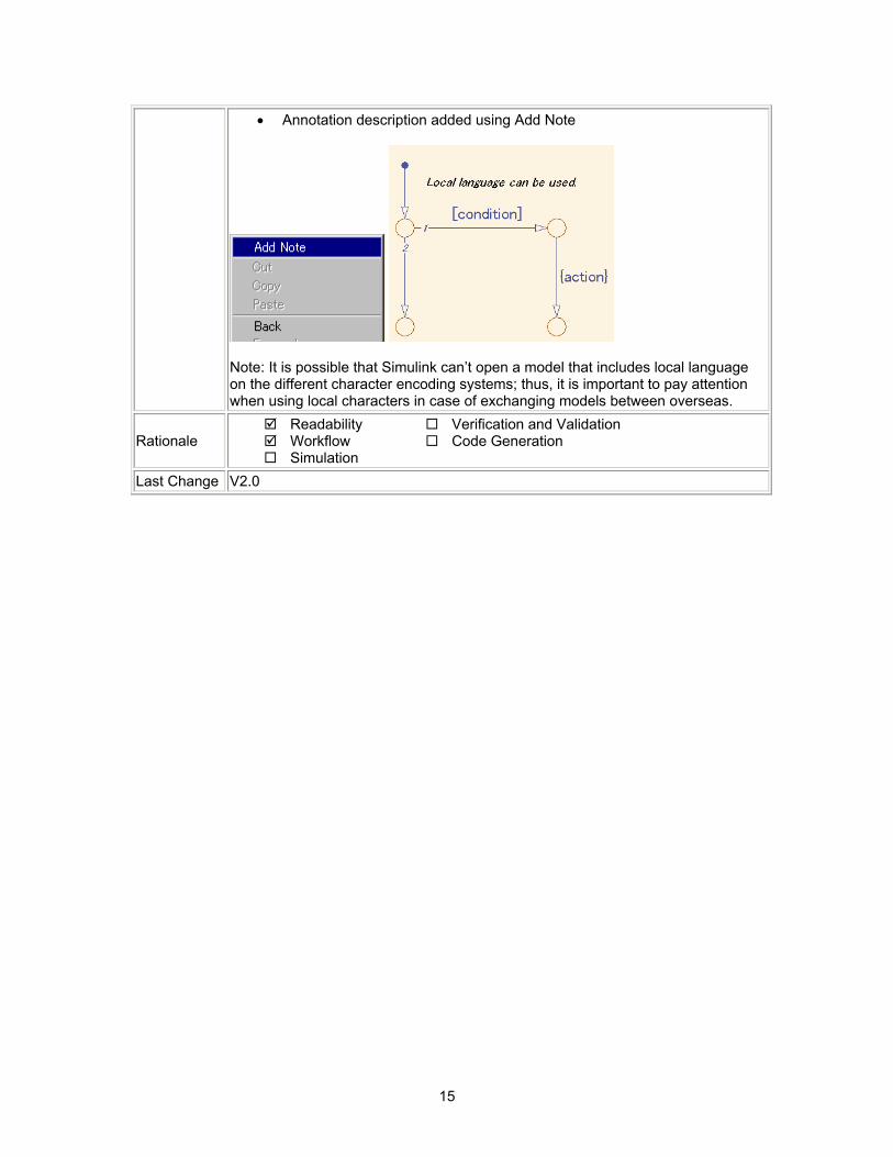
• Annotation description added using Add Note
Note: It is possible that Simulink can’t open a model that includes local language on the different character encoding systems; thus, it is important to pay attention when using local characters in case of exchanging models between overseas.
Rationale Readability Workflow Simulation
Verification and Validation Code Generation
Last Change V2.0
16
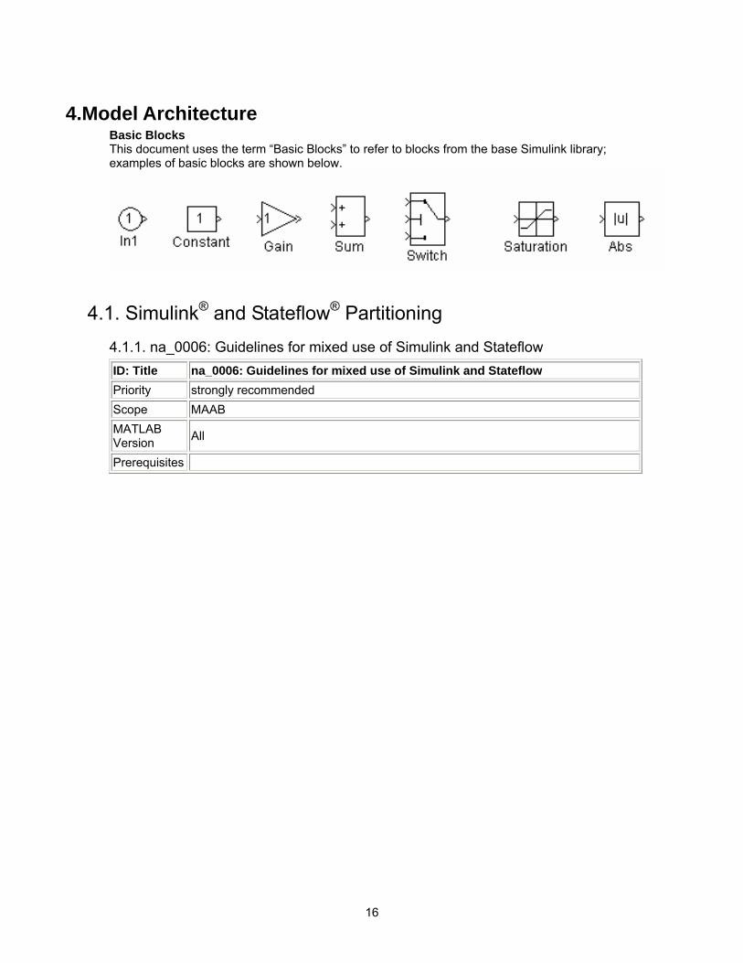
4.Model Architecture Basic Blocks This document uses the term “Basic Blocks” to refer to blocks from the base Simulink library; examples of basic blocks are shown below.
4.1. Simulink® and Stateflow® Partitioning 4.1.1. na_0006: Guidelines for mixed use of Simulink and Stateflow ID: Title na_0006: Guidelines for mixed use of Simulink and Stateflow Priority strongly recommended Scope MAAB MATLAB Version All
Prerequisites
17
Description
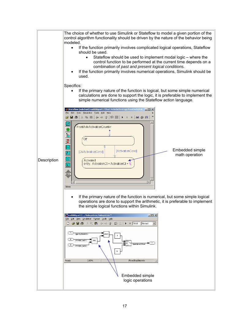
The choice of whether to use Simulink or Stateflow to model a given portion of the control algorithm functionality should be driven by the nature of the behavior being modeled.
• If the function primarily involves complicated logical operations, Stateflow should be used.
• Stateflow should be used to implement modal logic – where the control function to be performed at the current time depends on a combination of past and present logical conditions.
• If the function primarily involves numerical operations, Simulink should be used.
Specifics:
• If the primary nature of the function is logical, but some simple numerical calculations are done to support the logic, it is preferable to implement the simple numerical functions using the Stateflow action language.
• If the primary nature of the function is numerical, but some simple logical operations are done to support the arithmetic, it is preferable to implement the simple logical functions within Simulink.
Embedded simple math operation
Embedded simple logic operations
18
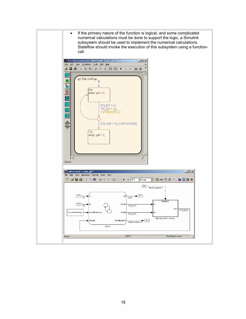
• If the primary nature of the function is logical, and some complicated numerical calculations must be done to support the logic, a Simulink subsystem should be used to implement the numerical calculations. Stateflow should invoke the execution of this subsystem using a function-call.
19
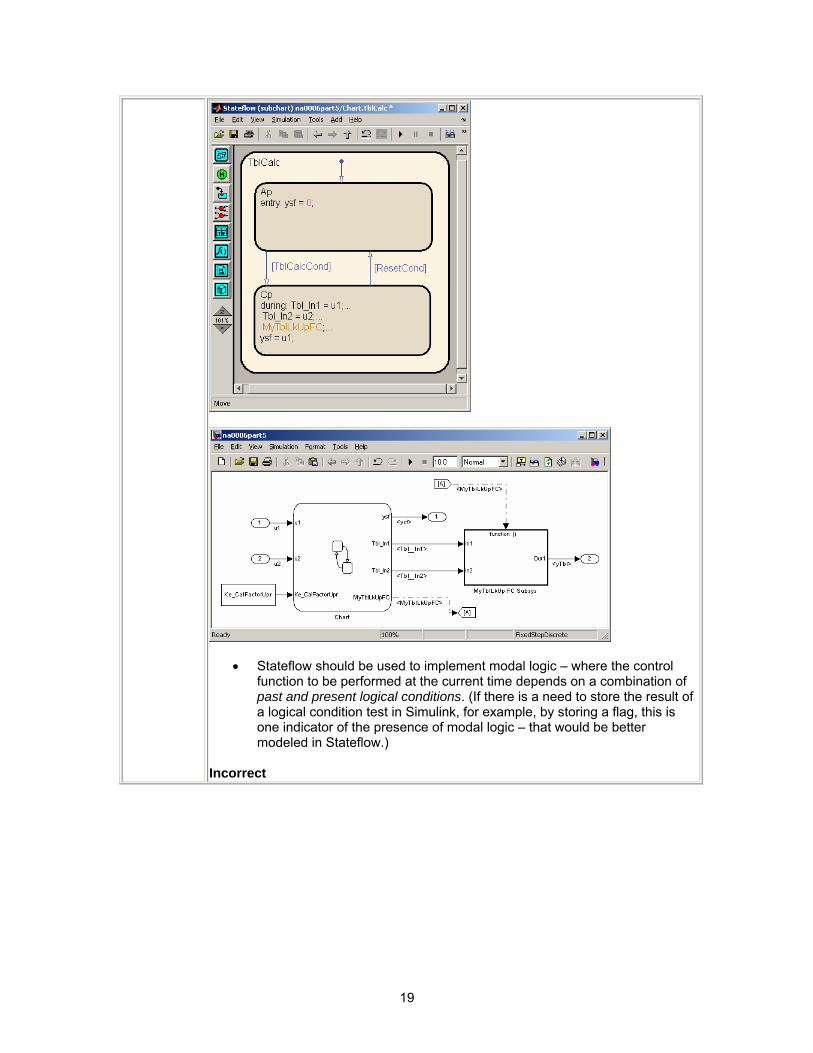
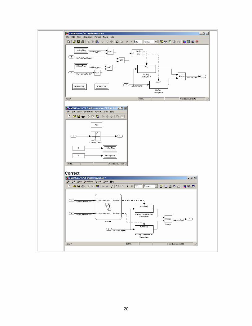
• Stateflow should be used to implement modal logic – where the control function to be performed at the current time depends on a combination of past and present logical conditions. (If there is a need to store the result of a logical condition test in Simulink, for example, by storing a flag, this is one indicator of the presence of modal logic – that would be better modeled in Stateflow.)
Incorrect
20
Correct
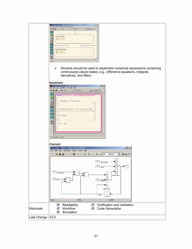
21
• Simulink should be used to implement numerical expressions containing continuously-valued states, e.g., difference equations, integrals, derivatives, and filters.
Incorrect
Correct
Rationale Readability Workflow Simulation
Verification and Validation Code Generation
Last Change V2.0
22
4.1.2. na_0007: Guidelines for use of Flow Charts, Truth Tables and State Machines ID: Title na_0007: Guidelines for use of Flow Charts, Truth Tables and State Machines Priority strongly recommended Scope MAAB MATLAB Version All
Prerequisites na_0006: Guidelines for Mixed use of Simulink and Stateflow
Description
Within Stateflow, the choice of whether to utilize a flow chart or a state chart to model a given portion of the control algorithm functionality should be driven by the nature of the behavior being modeled.
• If the primary nature of the function segment is to calculate modes of operation or discrete-valued states, then state charts should be used. Some examples are a diagnostic model with pass, fail, abort, and conflict states, or a model that calculates different modes of operation for a control algorithm.
• If the primary nature of the function segment involves if-then-else statements, then flowcharts or truth tables should be used.
Specifics:
• If the primary nature of the function segment is to calculate modes or states, but if-then-else statements are required, it is recommended that a flow chart be added to a state within the state chart. (refer to 7.5 Flowchart Patterns)
Rationale Readability Workflow Simulation
Verification and Validation Code Generation
Last Change V2.0
4.2. Subsystem Hierarchies 4.2.1. db_0143: Similar block types on the model levels ID: Title db_0143: Similar block types on the model levels Priority strongly recommended Scope NA-MAAB MATLAB Version All
Prerequisites
Description
Every level of a model must be designed with building blocks of the same type. (i.e. only subsystems or only basic blocks).
Blocks which can be placed on every model level:
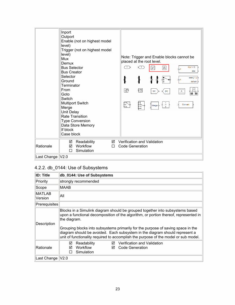
23
Inport Outport Enable (not on highest model level) Trigger (not on highest model level) Mux Demux Bus Selector Bus Creator Selector Ground Terminator From Goto Switch Multiport Switch Merge Unit Delay Rate Transition Type Conversion Data Store Memory If block Case block
Note: Trigger and Enable blocks cannot be placed at the root level.
Rationale Readability Workflow Simulation
Verification and Validation Code Generation
Last Change V2.0
4.2.2. db_0144: Use of Subsystems ID: Title db_0144: Use of Subsystems Priority strongly recommended Scope MAAB MATLAB Version All
Prerequisites
Description
Blocks in a Simulink diagram should be grouped together into subsystems based upon a functional decomposition of the algorithm, or portion thereof, represented in the diagram. Grouping blocks into subsystems primarily for the purpose of saving space in the diagram should be avoided. Each subsystem in the diagram should represent a unit of functionality required to accomplish the purpose of the model or sub model.
Rationale Readability Workflow Simulation
Verification and Validation Code Generation
Last Change V2.0
24
4.2.3. db_0040: Model hierarchy ID: Title db_0040: Model hierarchy Priority strongly recommended Scope MAAB MATLAB Version All
Prerequisites
Description The model hierarchy should correspond to the functional structure of the control system.
Rationale Readability Workflow Simulation
Verification and Validation Code Generation
Last Change V2.0
4.3. J-MAAB Model Architecture Decomposition 4.3.1. jc_0301: Controller model ID: Title jc_0301: Controller model Priority mandatory Scope J-MAAB MATLAB Version All
Prerequisites
Description
Control models are organized using the following hierarchical structure. Details on each layer are provided in the latter rules.
• Top layer / root level • Trigger layer • Structure layer • Data flow layer
Use of the Trigger level is optional. In the diagram below “Type A” shows the use of a trigger level while “Type B“ shows a model without a trigger level.
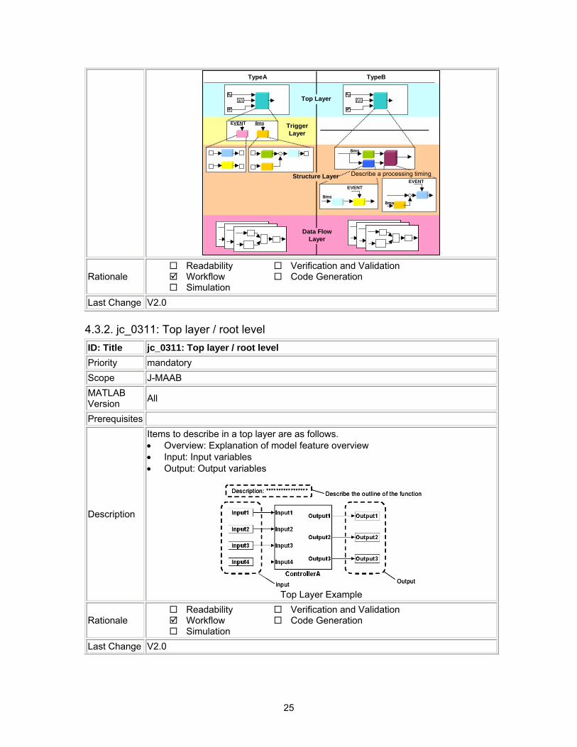
25
xxx レイヤー トリガレイヤ
A方式 B方式
処理タイミング記述
8ms
データフローレイヤ
トップレイヤ
8ms8ms
8ms
EVENTEVENT
EVENT
構造レイヤ
TypeA TypeB
Top Layer
TriggerLayer
Structure Layer Describe a processing timing
Data FlowLayer
Rationale Readability Workflow Simulation
Verification and Validation Code Generation
Last Change V2.0
4.3.2. jc_0311: Top layer / root level ID: Title jc_0311: Top layer / root level Priority mandatory Scope J-MAAB MATLAB Version All
Prerequisites
Description
Items to describe in a top layer are as follows. • Overview: Explanation of model feature overview • Input: Input variables • Output: Output variables
Describe the outline of the functionDescription: *****************
Input Output
Describe the outline of the functionDescription: *****************
Input Output Top Layer Example
Rationale Readability Workflow Simulation
Verification and Validation Code Generation
Last Change V2.0
26
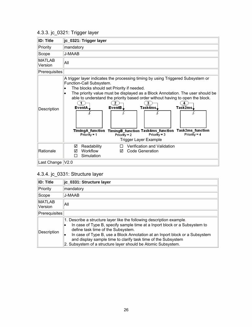
4.3.3. jc_0321: Trigger layer ID: Title jc_0321: Trigger layer Priority mandatory Scope J-MAAB MATLAB Version All
Prerequisites
Description
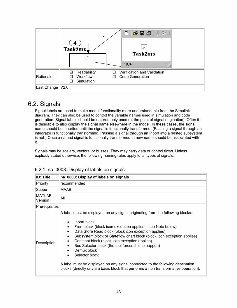
A trigger layer indicates the processing timing by using Triggered Subsystem or Function-Call Subsystem. • The blocks should set Priority if needed. • The priority value must be displayed as a Block Annotation. The user should be
able to understand the priority based order without having to open the block.
Trigger Layer Example
Rationale Readability Workflow Simulation
Verification and Validation Code Generation
Last Change V2.0
4.3.4. jc_0331: Structure layer ID: Title jc_0331: Structure layer Priority mandatory Scope J-MAAB MATLAB Version All
Prerequisites
Description
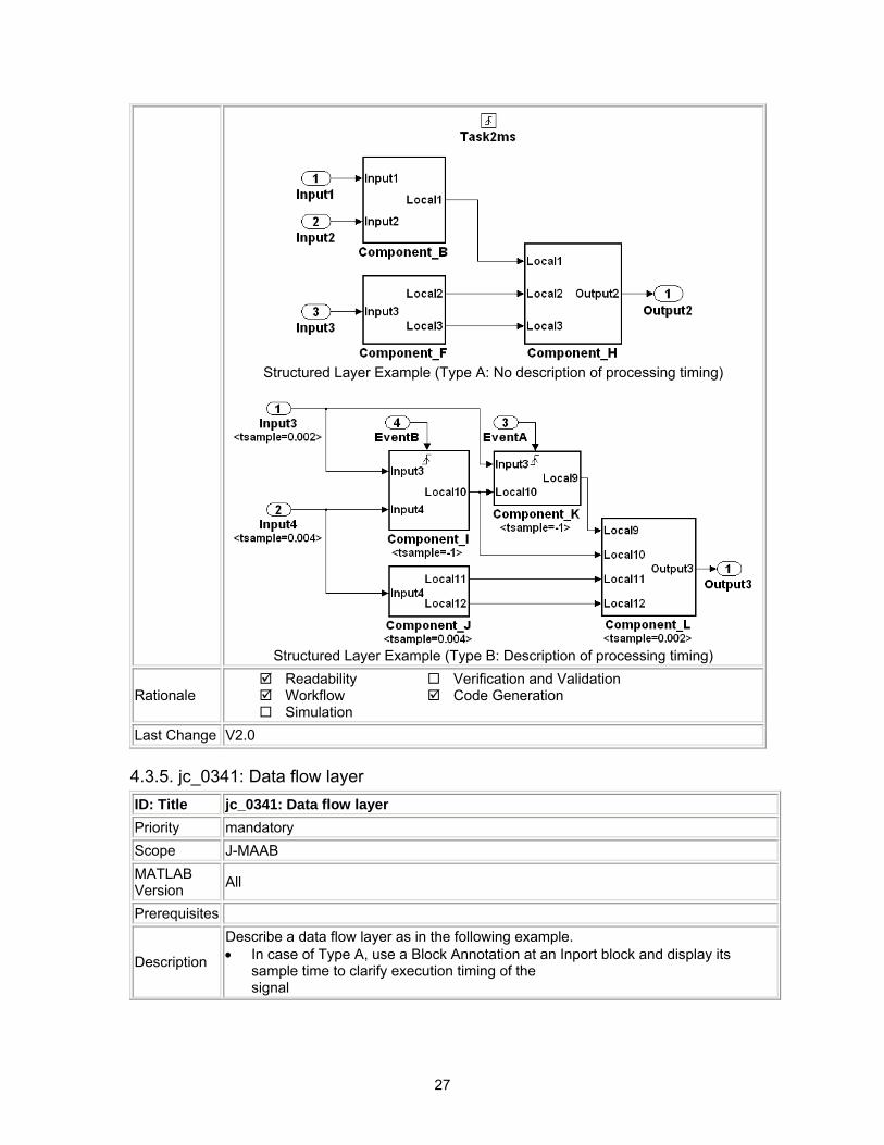
1. Describe a structure layer like the following description example. • In case of Type B, specify sample time at a Inport block or a Subsystem to
define task time of the Subsystem. • In case of Type B, use a Block Annotation at an Inport block or a Subsystem
and display sample time to clarify task time of the Subsystem 2. Subsystem of a structure layer should be Atomic Subsystem.
27
Structured Layer Example (Type A: No description of processing timing)
Structured Layer Example (Type B: Description of processing timing)
Rationale Readability Workflow Simulation
Verification and Validation Code Generation
Last Change V2.0
4.3.5. jc_0341: Data flow layer ID: Title jc_0341: Data flow layer Priority mandatory Scope J-MAAB MATLAB Version All
Prerequisites
Description
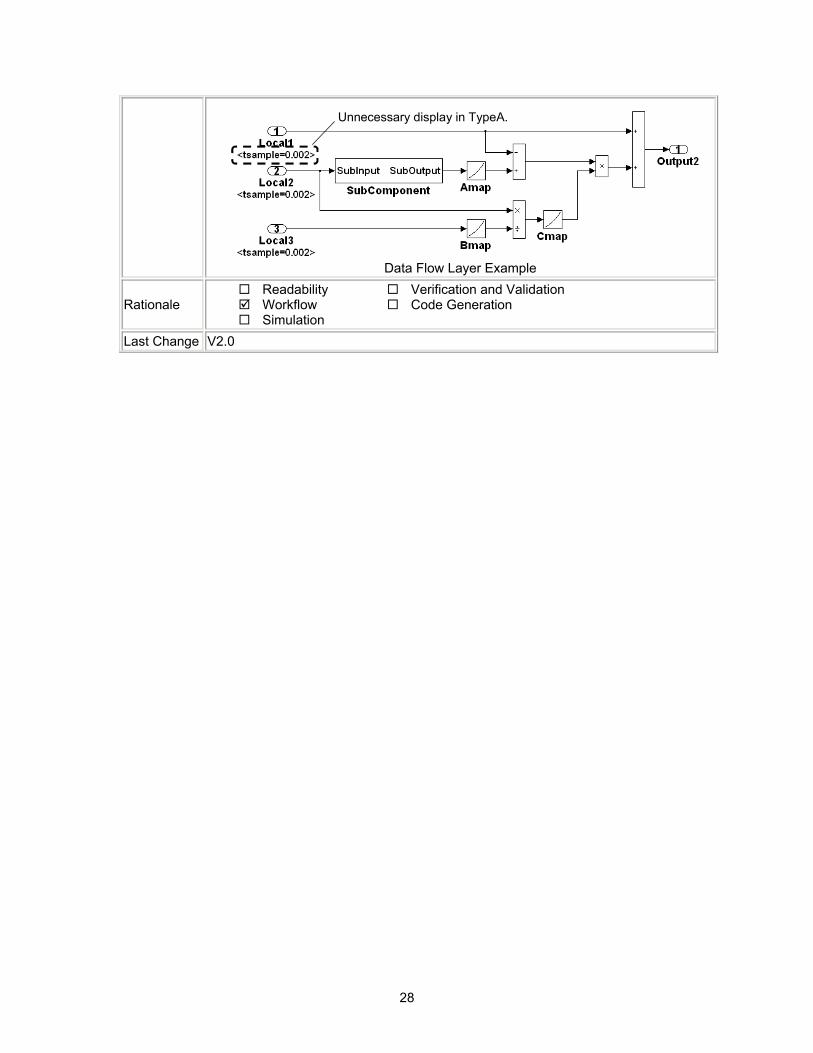
Describe a data flow layer as in the following example. • In case of Type A, use a Block Annotation at an Inport block and display its
sample time to clarify execution timing of the signal
28
Aタイプの場合は表示不要Unnecessary display in TypeA.
Data Flow Layer Example
Rationale Readability Workflow Simulation
Verification and Validation Code Generation
Last Change V2.0
29
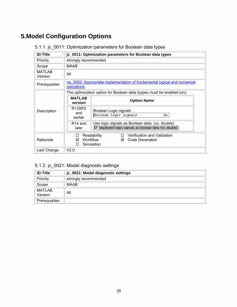
5.Model Configuration Options 5.1.1. jc_0011: Optimization parameters for Boolean data types ID:Title jc_0011: Optimization parameters for Boolean data types Priority strongly recommended Scope MAAB MATLAB Version All
Prerequisites na_0002: Appropriate implementation of fundamental logical and numerical operations
Description
The optimization option for Boolean data tyypes must be enabled (on). MATLAB version Option Name
R13SP2 and
earlier
Boolean Logic signals
R14 and later
Use logic signals as Boolean data. (vs. double)
Rationale Readability Workflow Simulation
Verification and Validation Code Generation
Last Change V2.0
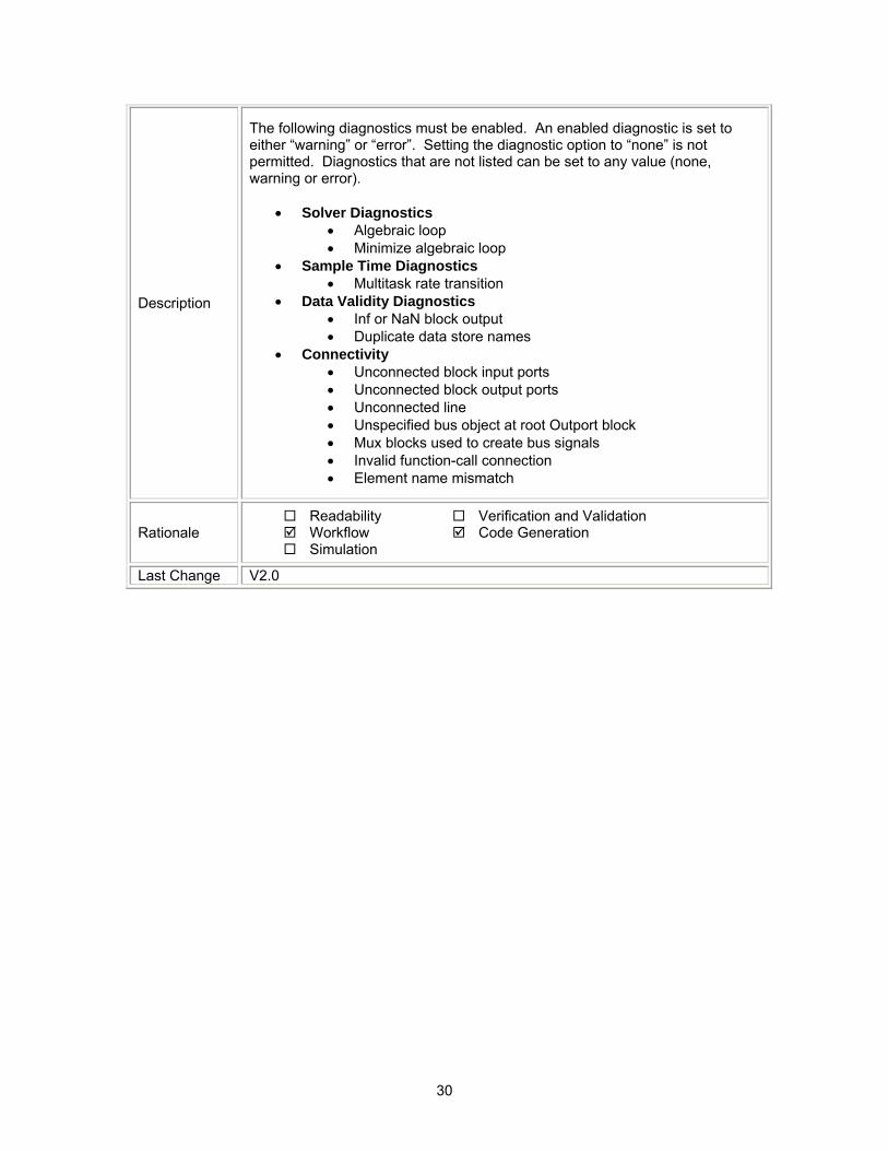
5.1.2. jc_0021: Model diagnostic settings ID:Title jc_0021: Model diagnostic settings Priority strongly recommended Scope MAAB MATLAB Version All
Prerequisites
30
Description
The following diagnostics must be enabled. An enabled diagnostic is set to either “warning” or “error”. Setting the diagnostic option to “none” is not permitted. Diagnostics that are not listed can be set to any value (none, warning or error).
• Solver Diagnostics • Algebraic loop • Minimize algebraic loop
• Sample Time Diagnostics • Multitask rate transition
• Data Validity Diagnostics • Inf or NaN block output • Duplicate data store names
• Connectivity • Unconnected block input ports • Unconnected block output ports • Unconnected line • Unspecified bus object at root Outport block • Mux blocks used to create bus signals • Invalid function-call connection • Element name mismatch
Rationale Readability Workflow Simulation
Verification and Validation Code Generation
Last Change V2.0
31
6.Simulink
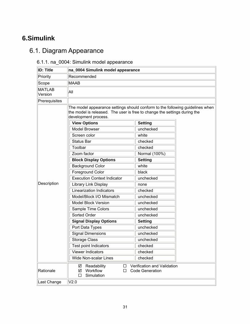
6.1. Diagram Appearance 6.1.1. na_0004: Simulink model appearance ID: Title na_0004 Simulink model appearance Priority Recommended Scope MAAB MATLAB Version All
Prerequisites
Description
The model appearance settings should conform to the following guidelines when the model is released. The user is free to change the settings during the development process.
View Options Setting Model Browser unchecked Screen color white Status Bar checked Toolbar checked Zoom factor Normal (100%) Block Display Options Setting Background Color white Foreground Color black Execution Context Indicator unchecked Library Link Display none Linearization Indicators checked Model/Block I/O Mismatch unchecked Model Block Version unchecked Sample Time Colors unchecked Sorted Order unchecked Signal Display Options Setting Port Data Types unchecked Signal Dimensions unchecked Storage Class unchecked Test point Indicators checked Viewer Indicators checked Wide Non-scalar Lines checked
Rationale Readability Workflow Simulation
Verification and Validation Code Generation
Last Change V2.0
32
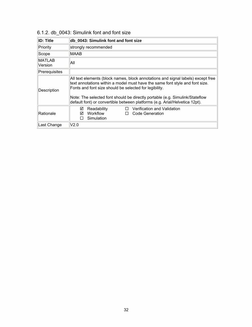
6.1.2. db_0043: Simulink font and font size ID: Title db_0043: Simulink font and font size Priority strongly recommended Scope MAAB MATLAB Version All
Prerequisites
Description
All text elements (block names, block annotations and signal labels) except free text annotations within a model must have the same font style and font size. Fonts and font size should be selected for legibility. Note: The selected font should be directly portable (e.g. Simulink/Stateflow default font) or convertible between platforms (e.g. Arial/Helvetica 12pt).
Rationale Readability Workflow Simulation
Verification and Validation Code Generation
Last Change V2.0

33
6.1.3. db_0042: Port block in Simulink models ID: Title db_0042: Port block in Simulink models Priority strongly recommended Scope MAAB MATLAB Version All
Prerequisites
Description
In a Simulink model, the ports comply with the following rules: • Inports should be placed on the left side of the diagram, but they can be
moved in to prevent signal crossings. • Outports should be placed on the right side, but they can be moved in to
prevent signal crossings. • Duplicate Inports can be used at the subsystem level if required but should
be avoided if possible. o Duplicate Inports cannot be used at the root level.
Correct
Incorrect
Notes on the incorrect model
• Inport 2 should be moved in so it does not cross the feed back loop lines. • Outport 1 should be moved to the right hand side of the diagram.
Rationale Readability Workflow Simulation
Verification and Validation Code Generation
Last Change V2.0
34
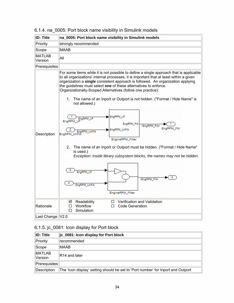
6.1.4. na_0005: Port block name visibility in Simulink models ID: Title na_0005: Port block name visibility in Simulink models Priority strongly recommended Scope MAAB MATLAB Version All
Prerequisites
Description
For some items while it is not possible to define a single approach that is applicable to all organizations’ internal processes, it is important that at least within a given organization a single consistent approach is followed. An organization applying the guidelines must select one of these alternatives to enforce. Organizationally-Scoped Alternatives (follow one practice):
1. The name of an Inport or Outport is not hidden. ("Format / Hide Name" is not allowed.)
2. The name of an Inport or Outport must be hidden. ("Format / Hide Name"
is used.) Exception: inside library subsystem blocks, the names may not be hidden.
Rationale Readability Workflow Simulation
Verification and Validation Code Generation
Last Change V2.0
6.1.5. jc_0081: Icon display for Port block ID: Title jc_0081: Icon display for Port block Priority recommended Scope MAAB MATLAB Version R14 and later
Prerequisites Description The ‘Icon display’ setting should be set to ‘Port number’ for Inport and Outport
35
blocks. Correct
Incorrect
Rationale Readability Workflow Simulation
Verification and Validation Code Generation
Last Change V2.0
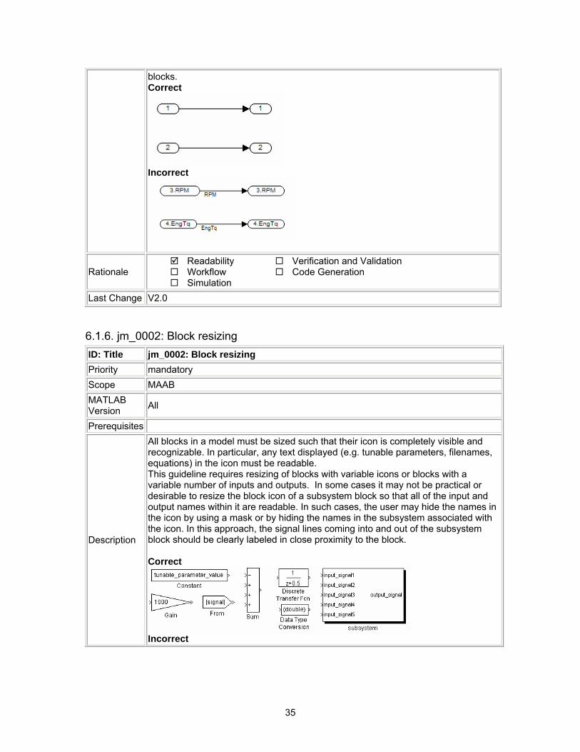
6.1.6. jm_0002: Block resizing ID: Title jm_0002: Block resizing Priority mandatory Scope MAAB MATLAB Version All
Prerequisites
Description
All blocks in a model must be sized such that their icon is completely visible and recognizable. In particular, any text displayed (e.g. tunable parameters, filenames, equations) in the icon must be readable. This guideline requires resizing of blocks with variable icons or blocks with a variable number of inputs and outputs. In some cases it may not be practical or desirable to resize the block icon of a subsystem block so that all of the input and output names within it are readable. In such cases, the user may hide the names in the icon by using a mask or by hiding the names in the subsystem associated with the icon. In this approach, the signal lines coming into and out of the subsystem block should be clearly labeled in close proximity to the block. Correct
Incorrect
36
Rationale Readability Workflow Simulation
Verification and Validation Code Generation
Last Change V2.0
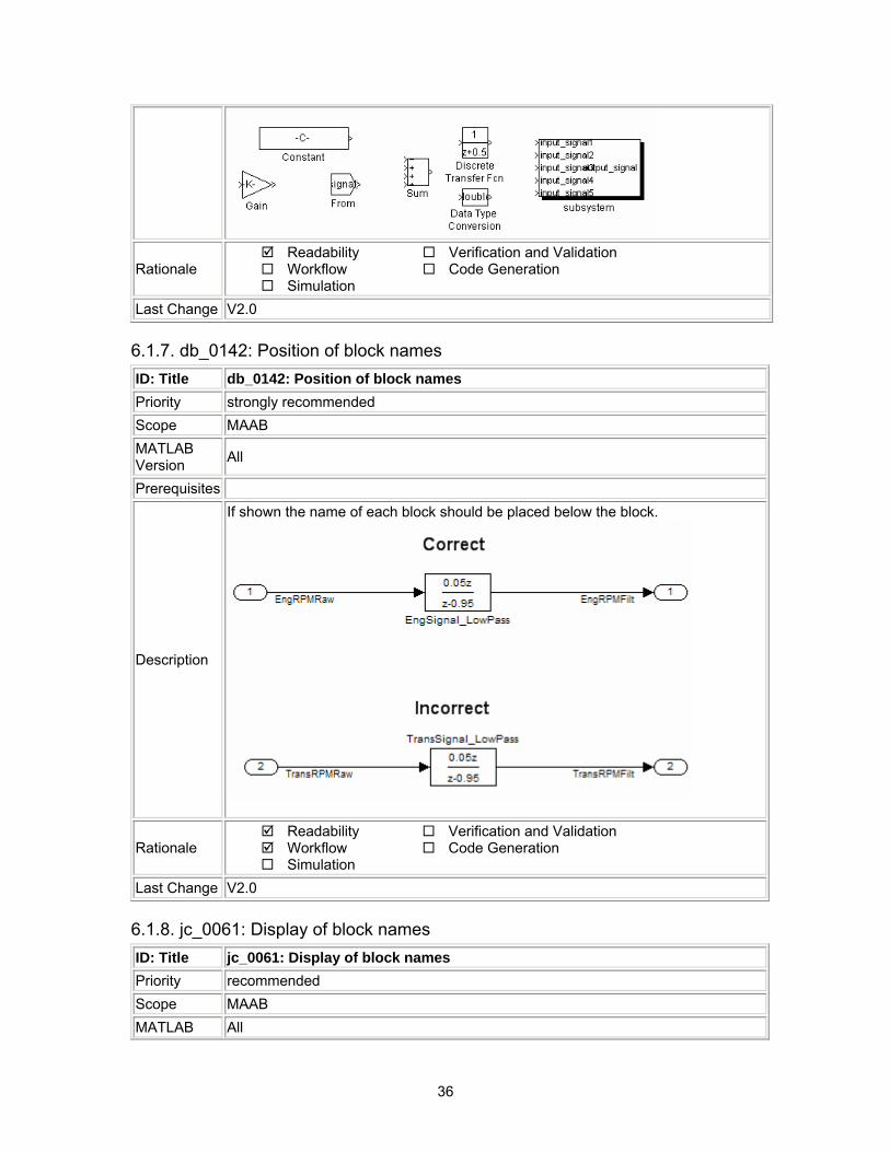
6.1.7. db_0142: Position of block names ID: Title db_0142: Position of block names Priority strongly recommended Scope MAAB MATLAB Version All
Prerequisites
Description
If shown the name of each block should be placed below the block.
Rationale Readability Workflow Simulation
Verification and Validation Code Generation
Last Change V2.0
6.1.8. jc_0061: Display of block names ID: Title jc_0061: Display of block names Priority recommended Scope MAAB MATLAB All
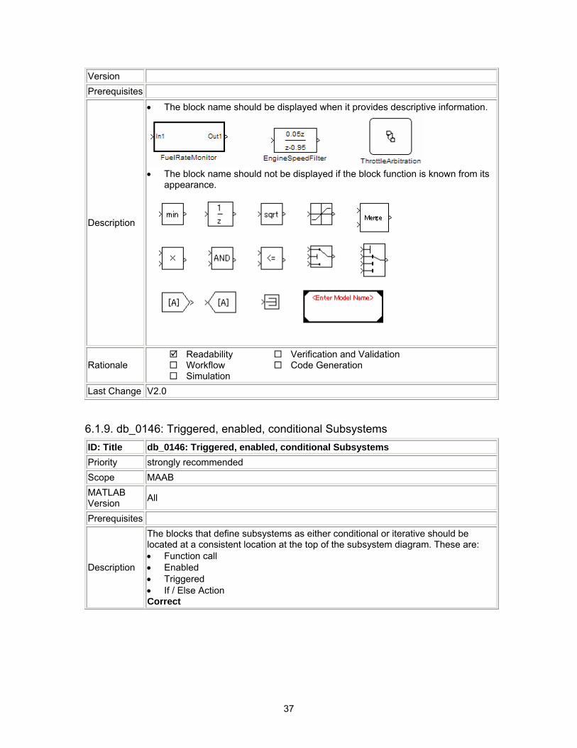
37
Version Prerequisites
Description
• The block name should be displayed when it provides descriptive information.
• The block name should not be displayed if the block function is known from its
appearance.
Rationale Readability Workflow Simulation
Verification and Validation Code Generation
Last Change V2.0
6.1.9. db_0146: Triggered, enabled, conditional Subsystems ID: Title db_0146: Triggered, enabled, conditional Subsystems Priority strongly recommended Scope MAAB MATLAB Version All
Prerequisites
Description
The blocks that define subsystems as either conditional or iterative should be located at a consistent location at the top of the subsystem diagram. These are: • Function call • Enabled • Triggered • If / Else Action Correct
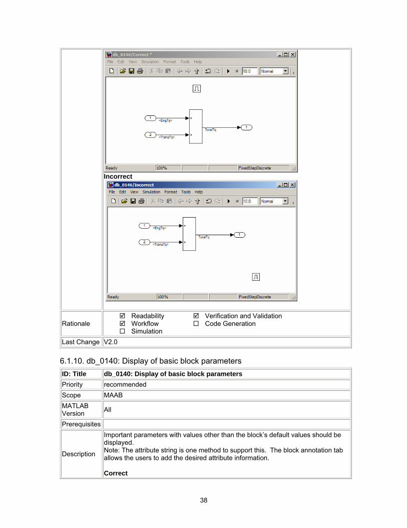
38
Incorrect
Rationale Readability Workflow Simulation
Verification and Validation Code Generation
Last Change V2.0
6.1.10. db_0140: Display of basic block parameters ID: Title db_0140: Display of basic block parameters Priority recommended Scope MAAB MATLAB Version All
Prerequisites
Description
Important parameters with values other than the block’s default values should be displayed. Note: The attribute string is one method to support this. The block annotation tab allows the users to add the desired attribute information. Correct
39
Rationale Readability Workflow Simulation
Verification and Validation Code Generation
Last Change V2.0
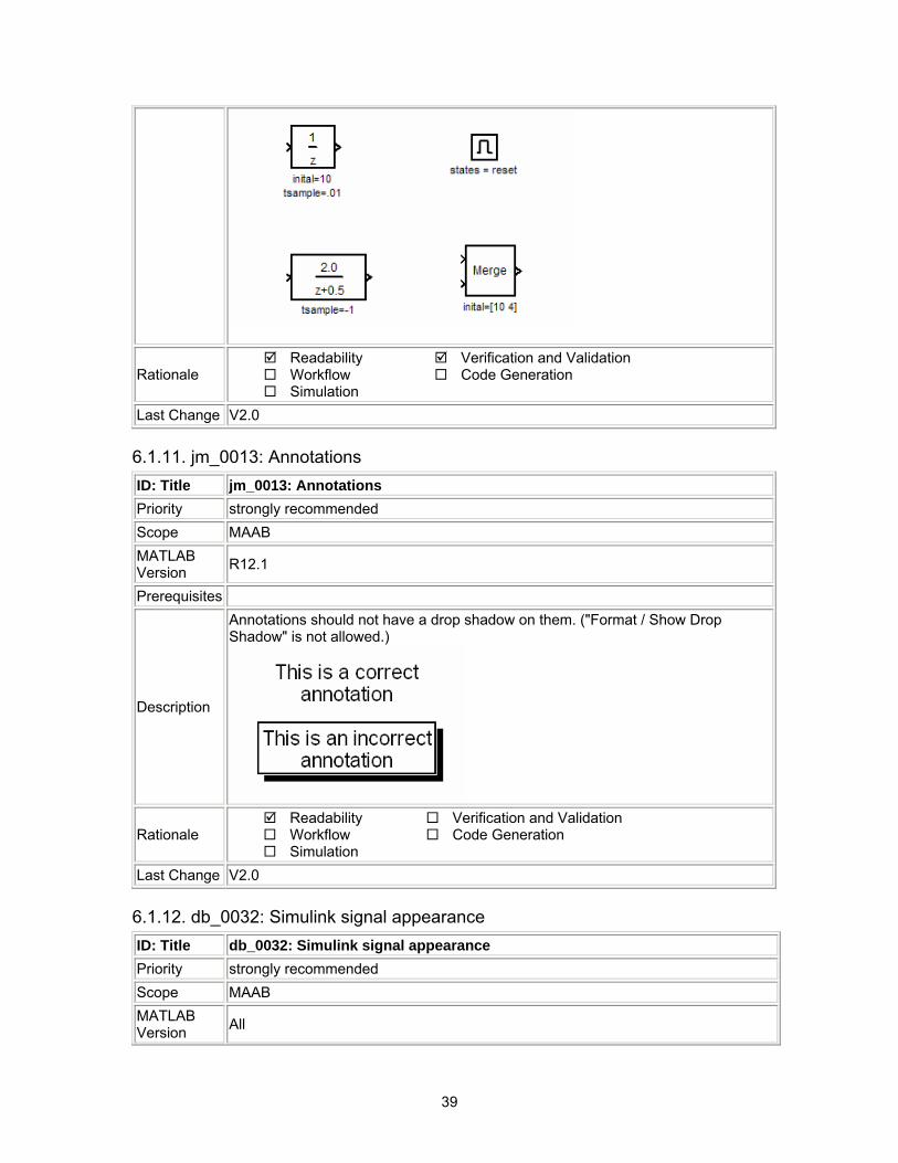
6.1.11. jm_0013: Annotations ID: Title jm_0013: Annotations Priority strongly recommended Scope MAAB MATLAB Version R12.1
Prerequisites
Description
Annotations should not have a drop shadow on them. ("Format / Show Drop Shadow" is not allowed.)
Rationale Readability Workflow Simulation
Verification and Validation Code Generation
Last Change V2.0
6.1.12. db_0032: Simulink signal appearance ID: Title db_0032: Simulink signal appearance Priority strongly recommended Scope MAAB MATLAB Version All
40
Prerequisites
Description
Signal lines • Should not cross each other, if possible. • Are drawn with right angles. • Are not drawn one upon the other. • Do not cross any blocks. • Should not split into more than two sub lines at a single branching point.
Correct
Incorrect
Rationale Readability Workflow Simulation
Verification and Validation Code Generation
Last Change V2.0
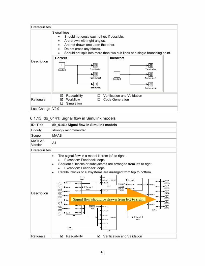
6.1.13. db_0141: Signal flow in Simulink models ID: Title db_0141: Signal flow in Simulink models Priority strongly recommended Scope MAAB MATLAB Version All
Prerequisites
Description
• The signal flow in a model is from left to right. • Exception: Feedback loops
• Sequential blocks or subsystems are arranged from left to right. • Exception: Feedback loops
• Parallel blocks or subsystems are arranged from top to bottom.
Signal flow should be drawn from left to rightSignal flow should be drawn from left to right
Rationale Readability Verification and Validation
41
Workflow Simulation
Code Generation
Last Change V2.0
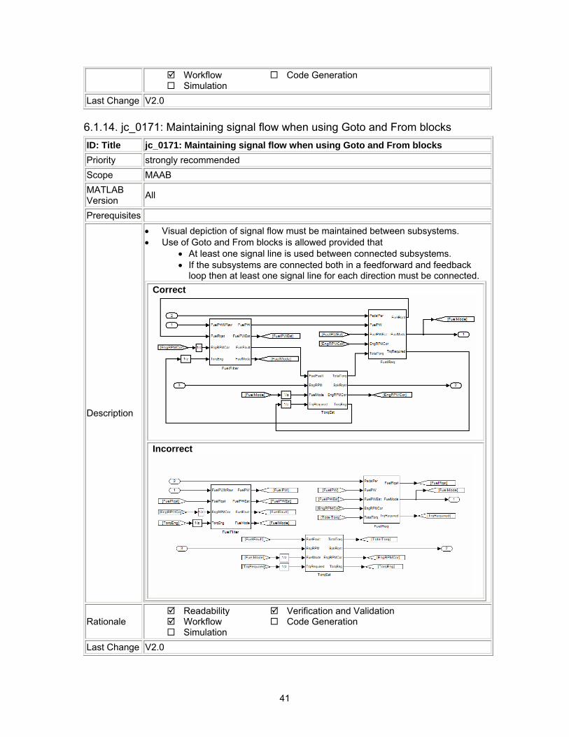
6.1.14. jc_0171: Maintaining signal flow when using Goto and From blocks ID: Title jc_0171: Maintaining signal flow when using Goto and From blocks Priority strongly recommended Scope MAAB MATLAB Version All
Prerequisites
Description
• Visual depiction of signal flow must be maintained between subsystems. • Use of Goto and From blocks is allowed provided that
• At least one signal line is used between connected subsystems. • If the subsystems are connected both in a feedforward and feedback
loop then at least one signal line for each direction must be connected. Correct
Incorrect
Rationale Readability Workflow Simulation
Verification and Validation Code Generation
Last Change V2.0
42
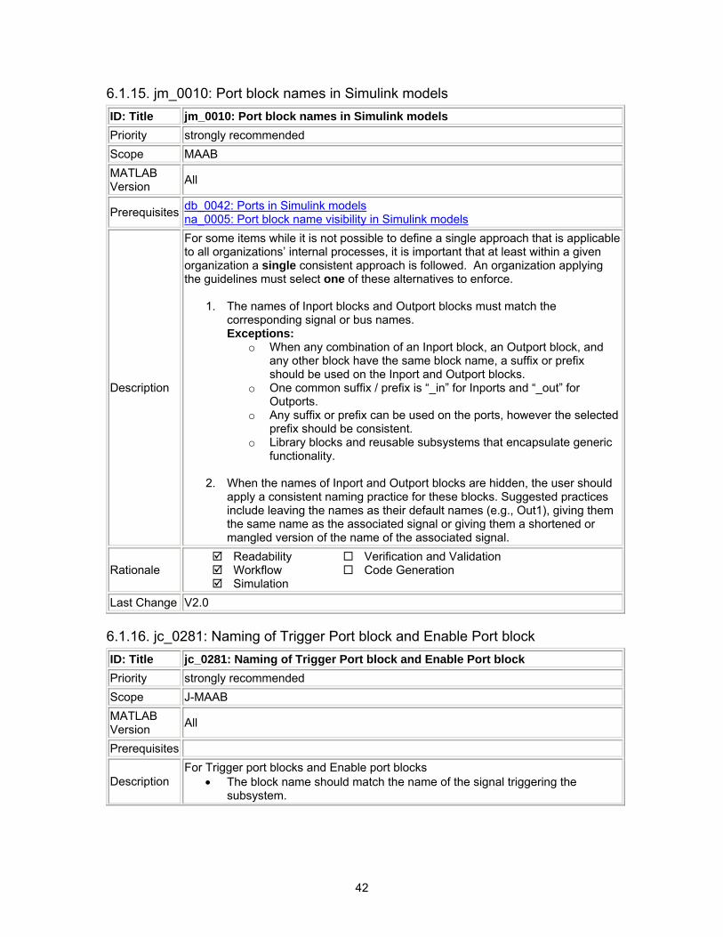
6.1.15. jm_0010: Port block names in Simulink models ID: Title jm_0010: Port block names in Simulink models Priority strongly recommended Scope MAAB MATLAB Version All
Prerequisites db_0042: Ports in Simulink models na_0005: Port block name visibility in Simulink models
Description
For some items while it is not possible to define a single approach that is applicable to all organizations’ internal processes, it is important that at least within a given organization a single consistent approach is followed. An organization applying the guidelines must select one of these alternatives to enforce.
1. The names of Inport blocks and Outport blocks must match the corresponding signal or bus names. Exceptions:
o When any combination of an Inport block, an Outport block, and any other block have the same block name, a suffix or prefix should be used on the Inport and Outport blocks.
o One common suffix / prefix is “_in” for Inports and “_out” for Outports.
o Any suffix or prefix can be used on the ports, however the selected prefix should be consistent.
o Library blocks and reusable subsystems that encapsulate generic functionality.
2. When the names of Inport and Outport blocks are hidden, the user should
apply a consistent naming practice for these blocks. Suggested practices include leaving the names as their default names (e.g., Out1), giving them the same name as the associated signal or giving them a shortened or mangled version of the name of the associated signal.
Rationale Readability Workflow Simulation
Verification and Validation Code Generation
Last Change V2.0
6.1.16. jc_0281: Naming of Trigger Port block and Enable Port block ID: Title jc_0281: Naming of Trigger Port block and Enable Port block Priority strongly recommended Scope J-MAAB MATLAB Version All
Prerequisites
Description For Trigger port blocks and Enable port blocks
• The block name should match the name of the signal triggering the subsystem.
43
Rationale Readability Workflow Simulation
Verification and Validation Code Generation
Last Change V2.0
6.2. Signals Signal labels are used to make model functionality more understandable from the Simulink diagram. They can also be used to control the variable names used in simulation and code generation. Signal labels should be entered only once (at the point of signal origination). Often it is desirable to also display the signal name elsewhere in the model. In these cases, the signal name should be inherited until the signal is functionally transformed. (Passing a signal through an integrator is functionally transforming. Passing a signal through an Inport into a nested subsystem is not.) Once a named signal is functionally transformed, a new name should be associated with it. Signals may be scalars, vectors, or busses. They may carry data or control flows. Unless explicitly stated otherwise, the following naming rules apply to all types of signals.
6.2.1. na_0008: Display of labels on signals ID: Title na_0008: Display of labels on signals Priority recommended Scope MAAB MATLAB Version All
Prerequisites
Description
A label must be displayed on any signal originating from the following blocks:
• Inport block • From block (block icon exception applies – see Note below) • Data Store Read block (block icon exception applies) • Subsystem block or Stateflow chart block (block icon exception applies) • Constant block (block icon exception applies) • Bus Selector block (the tool forces this to happen) • Demux block • Selector block
A label must be displayed on any signal connected to the following destination blocks (directly or via a basic block that performs a non transformative operation):

44
• Outport block • Goto block • Data Store Write block • Bus Creator block • Mux block • Subsystem block • Chart block
Note: Block icon exception (applicable only where called out above): If the signal label is visible in the originating block icon display, the connected signal need not also have the label displayed unless the signal label is needed elsewhere due to a destination-based rule.
• In addition, a label may be displayed on any other signal of interest to the user or the user’s customers.
Rationale Readability Workflow Simulation
Verification and Validation Code Generation
Last Change V2.0
6.2.2. na_0009: Entry versus propagation of signal labels ID: Title Na_0009: Entry versus propagation of signal labels Priority strongly recommended Scope MAAB MATLAB Version All
Prerequisites na_0008: Display of labels on signals
45
Description
If a label is present on a signal, the following rules define whether that label shall be created there (entered directly on the signal) or propagated from its true source (inherited from elsewhere in the model by using the ‘<’ character).
1. Any displayed signal label must be entered for signals that: a. Originate from an Inport at the Root (top) Level of a model b. Originate from a basic block that performs a transformative
operation (For the purpose of interpreting this rule only, the Bus Creator block, Mux block and Selector block shall be considered to be included among the blocks that perform transformative operations.)
2. Any displayed signal label must be propagated for signals that: a. Originate from an Inport block in a nested subsystem
Exception: If the nested subsystem is a library subsystem, a label may be entered on the signal coming from the Inport to accommodate reuse of the library block.
b. Originate from a basic block that performs a non-transformative operation
c. Originate from a Subsystem or Stateflow chart block Exception: If the connection originates from the output of a library subsystem block instance, a new label may be entered on the signal to accommodate reuse of the library block.
Rationale Readability Workflow Simulation
Verification and Validation Code Generation
Last Change V2.0
6.2.3. db_0097: Position of labels for signals and busses ID: Title db_0097: Position of labels for signals and busses Priority strongly recommended Scope MAAB MATLAB Version All
Prerequisites
Description The labels must be visually associated with the corresponding signal and not overlap other labels, signals or blocks.
46
Labels should be located consistently below horizontal lines and close to the corresponding source or destination block.
Rationale Readability Workflow Simulation
Verification and Validation Code Generation
Last Change V2.0
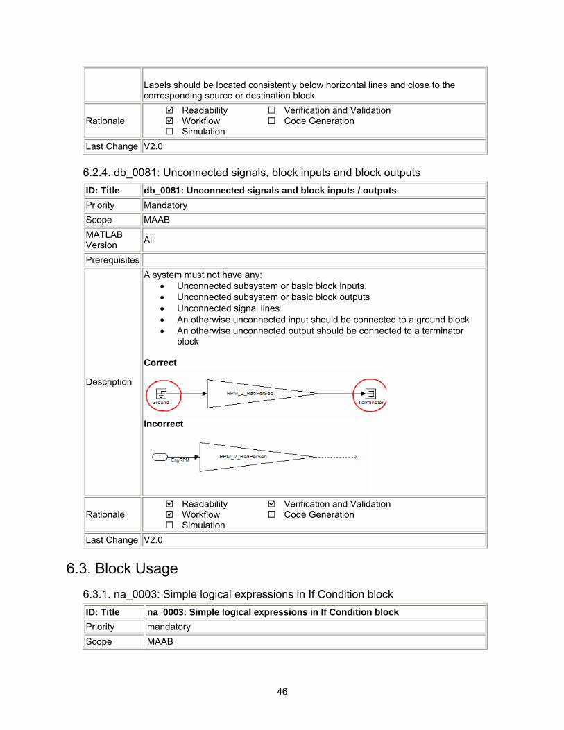
6.2.4. db_0081: Unconnected signals, block inputs and block outputs ID: Title db_0081: Unconnected signals and block inputs / outputs Priority Mandatory Scope MAAB MATLAB Version All
Prerequisites
Description
A system must not have any: • Unconnected subsystem or basic block inputs. • Unconnected subsystem or basic block outputs • Unconnected signal lines • An otherwise unconnected input should be connected to a ground block • An otherwise unconnected output should be connected to a terminator
block Correct
Incorrect
Rationale Readability Workflow Simulation
Verification and Validation Code Generation
Last Change V2.0
6.3. Block Usage 6.3.1. na_0003: Simple logical expressions in If Condition block ID: Title na_0003: Simple logical expressions in If Condition block Priority mandatory Scope MAAB
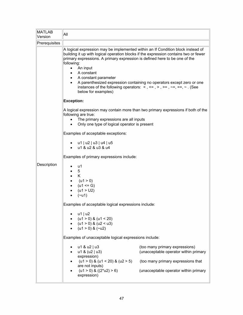
47
MATLAB Version All
Prerequisites
Description
A logical expression may be implemented within an If Condition block instead of building it up with logical operation blocks if the expression contains two or fewer primary expressions. A primary expression is defined here to be one of the following:
• An input • A constant • A constant parameter • A parenthesized expression containing no operators except zero or one
instances of the following operators: < , <= , > , >= , ~=, ==, ~ . (See below for examples)
Exception: A logical expression may contain more than two primary expressions if both of the following are true:
• The primary expressions are all inputs • Only one type of logical operator is present
Examples of acceptable exceptions:
• u1 | u2 | u3 | u4 | u5 • u1 & u2 & u3 & u4
Examples of primary expressions include:
• u1 • 5 • K • (u1 > 0) • (u1 <= G) • (u1 > U2) • (~u1)
Examples of acceptable logical expressions include:
• u1 | u2 • (u1 > 0) & (u1 < 20) • (u1 > 0) & (u2 < u3) • (u1 > 0) & (~u2)
Examples of unacceptable logical expressions include:
• u1 & u2 | u3 (too many primary expressions) • u1 & (u2 | u3) (unacceptable operator within primary
expression) • (u1 > 0) & (u1 < 20) & (u2 > 5) (too many primary expressions that
are not inputs) • (u1 > 0) & ((2*u2) > 6) (unacceptable operator within primary
expression)
48
Rationale Readability Workflow Simulation
Verification and Validation Code Generation
Last Change V2.0
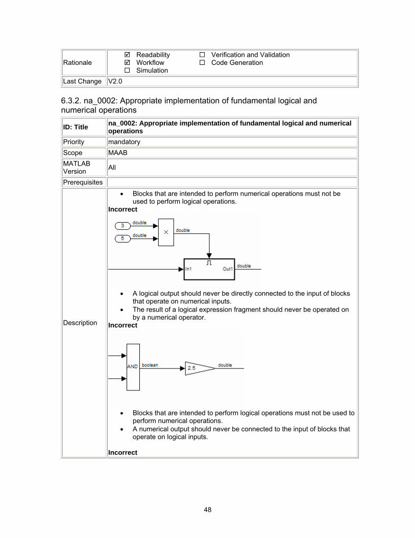
6.3.2. na_0002: Appropriate implementation of fundamental logical and numerical operations
ID: Title na_0002: Appropriate implementation of fundamental logical and numerical operations
Priority mandatory Scope MAAB MATLAB Version All
Prerequisites
Description
• Blocks that are intended to perform numerical operations must not be used to perform logical operations.
Incorrect
• A logical output should never be directly connected to the input of blocks
that operate on numerical inputs. • The result of a logical expression fragment should never be operated on
by a numerical operator. Incorrect
• Blocks that are intended to perform logical operations must not be used to
perform numerical operations. • A numerical output should never be connected to the input of blocks that
operate on logical inputs. Incorrect
49
Rationale Readability Workflow Simulation
Verification and Validation Code Generation
Last Change V2.0
6.3.3. jm_0001: Prohibited Simulink standard blocks inside controllers ID: Title jm_0001: Prohibited Simulink standard blocks inside controllers Priority mandatory Scope MAAB MATLAB Version All
Prerequisites
Description
Controller models must be designed from discrete blocks. Sources are not allowed: Signal Generator Step Ramp Sine Wave Repeating Sequence Discrete Pulse Generator Pulse Generator Chirp Signal Clock Digital Clock From File From Workspace Random Number Uniform Random Number Band-Limited White Noise
Continuous blocks are not allowed:
50
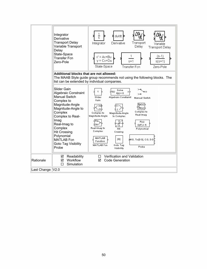
Integrator Derivative Transport Delay Variable Transport Delay State-Space Transfer Fcn Zero-Pole
Additional blocks that are not allowed: The MAAB Style guide group recommends not using the following blocks. The list can be extended by individual companies.
Slider Gain Algebraic Constraint Manual Switch Complex to Magnitude-Angle Magnitude-Angle to Complex Complex to Real-Imag Real-Imag to Complex Hit Crossing Polynomial MATLAB Fcn Goto Tag Visibility Probe
Rationale Readability Workflow Simulation
Verification and Validation Code Generation
Last Change V2.0
51
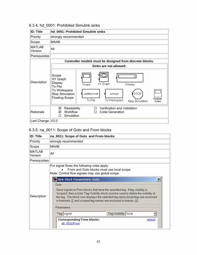
6.3.4. hd_0001: Prohibited Simulink sinks
6.3.5. na_0011: Scope of Goto and From blocks ID: Title na_0011: Scope of Goto and From blocks Priority strongly recommended Scope MAAB MATLAB Version All
Prerequisites
Description
For signal flows the following rules apply: • From and Goto blocks must use local scope.
Note: Control flow signals may use global scope.
ID: Title hd_0001: Prohibited Simulink sinks Priority strongly recommended Scope MAAB MATLAB Version All
Prerequisites
Description
Controller models must be designed from discrete blocks. Sinks are not allowed:
Scope XY Graph Display To File To Workspace Stop Simulation Floating Scope
Rationale Readability Workflow Simulation
Verification and Validation Code Generation
Last Change V2.0
52
Rationale Readability Workflow Simulation
Verification and Validation Code Generation
Last Change V2.0
6.3.6. jc_0141: Use of the Switch block ID: Title jc_0141: Use of the Switch block Priority strongly recommended Scope MAAB MATLAB Version All
Prerequisites
Description
The switch condition, input 2, must be a Boolean value. The block parameter “Criteria for passing first input” should be set to u2~=0. The block parameter “Criteria for passing first input” must not be set to u2>Threshold for R13 versions of MATLAB.
Correct
Incorrect
53
Rationale Readability Workflow Simulation
Verification and Validation Code Generation
Last Change V2.0
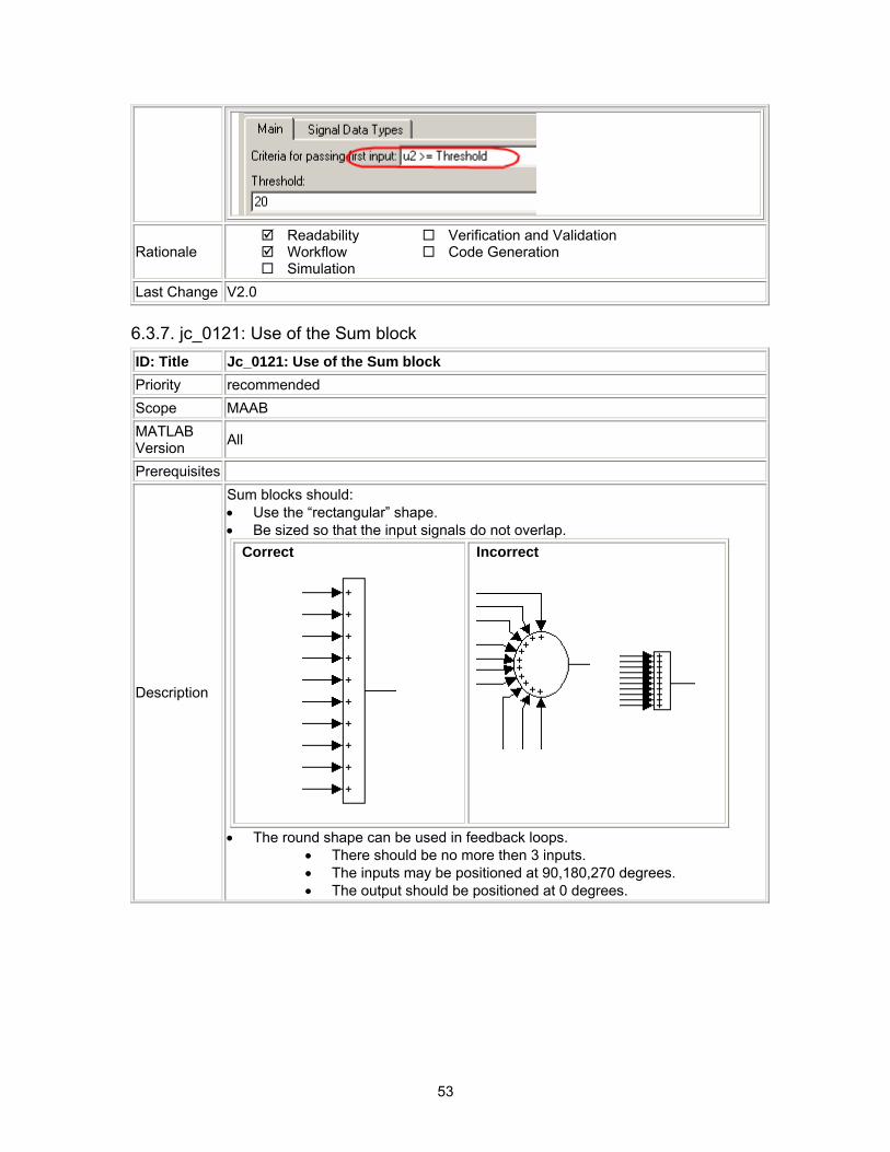
6.3.7. jc_0121: Use of the Sum block ID: Title Jc_0121: Use of the Sum block Priority recommended Scope MAAB MATLAB Version All
Prerequisites
Description
Sum blocks should: • Use the “rectangular” shape. • Be sized so that the input signals do not overlap.
Correct
Incorrect
• The round shape can be used in feedback loops.
• There should be no more then 3 inputs. • The inputs may be positioned at 90,180,270 degrees. • The output should be positioned at 0 degrees.
54
Correct
Incorrect
Correct
Incorrect
Rationale Readability Workflow Simulation
Verification and Validation Code Generation
Last Change V2.0
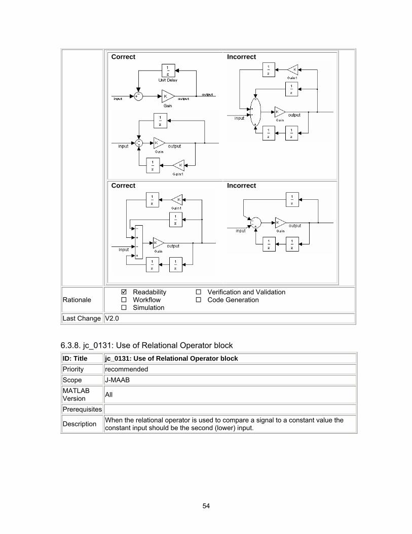
6.3.8. jc_0131: Use of Relational Operator block ID: Title jc_0131: Use of Relational Operator block Priority recommended Scope J-MAAB MATLAB Version All
Prerequisites
Description When the relational operator is used to compare a signal to a constant value the constant input should be the second (lower) input.
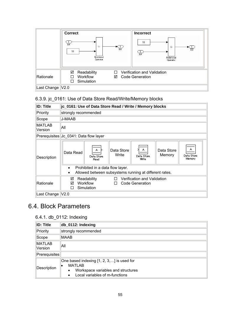
55
Correct
Incorrect
Rationale Readability Workflow Simulation
Verification and Validation Code Generation
Last Change V2.0
6.3.9. jc_0161: Use of Data Store Read/Write/Memory blocks ID: Title jc_0161: Use of Data Store Read / Write / Memory blocks Priority strongly recommended Scope J-MAAB MATLAB Version All
Prerequisites Jc_0341: Data flow layer
Description Data Read Data Store
Write Data Store
Memory
• Prohibited in a data flow layer. • Allowed between subsystems running at different rates.
Rationale Readability Workflow Simulation
Verification and Validation Code Generation
Last Change V2.0
6.4. Block Parameters 6.4.1. db_0112: Indexing ID: Title db_0112: Indexing Priority strongly recommended Scope MAAB MATLAB Version All
Prerequisites
Description
One based indexing [1, 2, 3,…] is used for • MATLAB
• Workspace variables and structures • Local variables of m-functions
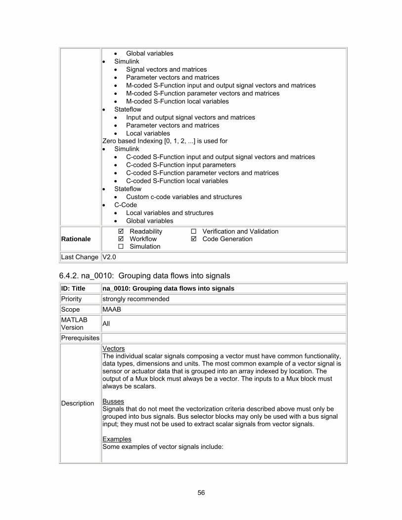
56
• Global variables • Simulink
• Signal vectors and matrices • Parameter vectors and matrices • M-coded S-Function input and output signal vectors and matrices • M-coded S-Function parameter vectors and matrices • M-coded S-Function local variables
• Stateflow • Input and output signal vectors and matrices • Parameter vectors and matrices • Local variables
Zero based Indexing [0, 1, 2, ...] is used for • Simulink
• C-coded S-Function input and output signal vectors and matrices • C-coded S-Function input parameters • C-coded S-Function parameter vectors and matrices • C-coded S-Function local variables
• Stateflow • Custom c-code variables and structures
• C-Code • Local variables and structures • Global variables
Rationale Readability Workflow Simulation
Verification and Validation Code Generation
Last Change V2.0
6.4.2. na_0010: Grouping data flows into signals ID: Title na_0010: Grouping data flows into signals Priority strongly recommended Scope MAAB MATLAB Version All
Prerequisites
Description
Vectors The individual scalar signals composing a vector must have common functionality, data types, dimensions and units. The most common example of a vector signal is sensor or actuator data that is grouped into an array indexed by location. The output of a Mux block must always be a vector. The inputs to a Mux block must always be scalars. Busses Signals that do not meet the vectorization criteria described above must only be grouped into bus signals. Bus selector blocks may only be used with a bus signal input; they must not be used to extract scalar signals from vector signals. Examples Some examples of vector signals include:
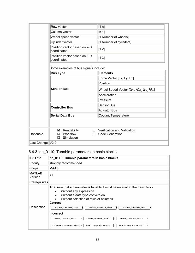
57
Row vector [1 n] Column vector [n 1] Wheel speed vector [1 Number of wheels] Cylinder vector [1 Number of cylinders] Position vector based on 2-D coordinates [1 2]
Position vector based on 3-D coordinates [1 3]
Some examples of bus signals include: Bus Type Elements
Force Vector [Fx, Fy, Fz] Position
Wheel Speed Vector [Θlf, Θrf, Θlr, Θrr]
Acceleration
Sensor Bus
Pressure Sensor Bus Controller Bus Actuator Bus
Serial Data Bus Coolant Temperature
Rationale Readability Workflow Simulation
Verification and Validation Code Generation
Last Change V2.0
6.4.3. db_0110: Tunable parameters in basic blocks ID: Title db_0110: Tunable parameters in basic blocks Priority strongly recommended Scope MAAB MATLAB Version All
Prerequisites
Description
To insure that a parameter is tunable it must be entered in the basic block • Without any expression. • Without a data type conversion. • Without selection of rows or columns.
Correct
Incorrect
58
Rationale Readability Workflow Simulation
Verification and Validation Code Generation
Last Change V2.0
6.5. Simulink Patterns The following rules illustrate sample patterns used in Simulink diagrams. As such they would normally be part of a much larger Simulink diagram.
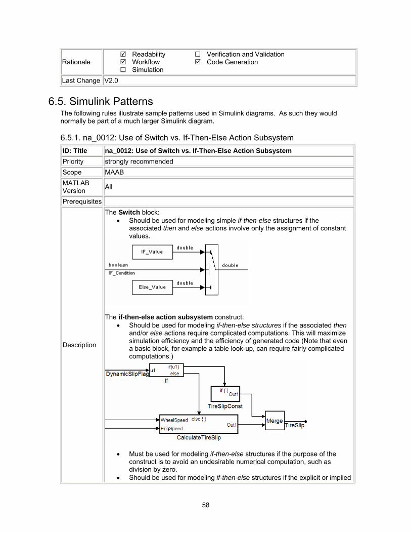
6.5.1. na_0012: Use of Switch vs. If-Then-Else Action Subsystem ID: Title na_0012: Use of Switch vs. If-Then-Else Action Subsystem Priority strongly recommended Scope MAAB MATLAB Version All
Prerequisites
Description
The Switch block: • Should be used for modeling simple if-then-else structures if the
associated then and else actions involve only the assignment of constant values.
The if-then-else action subsystem construct:
• Should be used for modeling if-then-else structures if the associated then and/or else actions require complicated computations. This will maximize simulation efficiency and the efficiency of generated code (Note that even a basic block, for example a table look-up, can require fairly complicated computations.)
• Must be used for modeling if-then-else structures if the purpose of the construct is to avoid an undesirable numerical computation, such as division by zero.
• Should be used for modeling if-then-else structures if the explicit or implied
59
then or the else action is just to hold the associated output value(s). In other cases, the degree of complexity of the then and/or else action computations and the intelligence of the Simulink simulation and code generation engines will determine the appropriate construct. These statements also apply to more complicated nested and cascaded if-then-else structures and case structure implementations.
Rationale Readability Workflow Simulation
Verification and Validation Code Generation
Last Change V2.0
6.5.2. db_0114: Simulink patterns for If-then-else-if constructs ID: Title db_0114: Simulink patterns for If-then-else-if constructs Priority strongly recommended Scope MAAB MATLAB Version All
Prerequisites
Description
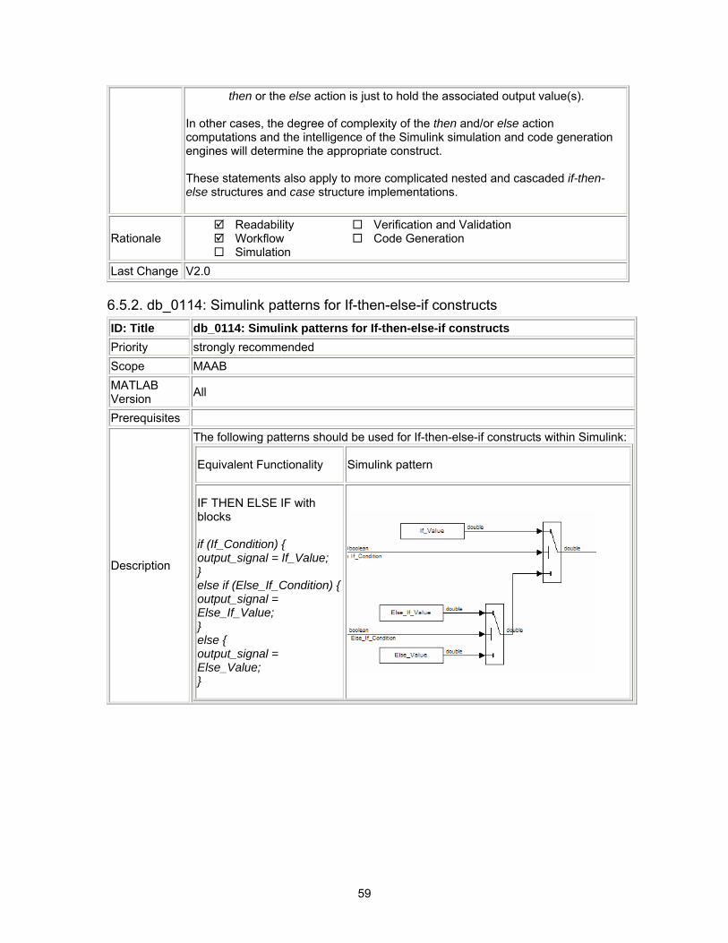
The following patterns should be used for If-then-else-if constructs within Simulink:
Equivalent Functionality Simulink pattern
IF THEN ELSE IF with blocks if (If_Condition) { output_signal = If_Value; } else if (Else_If_Condition) {output_signal = Else_If_Value; } else { output_signal = Else_Value; }
60
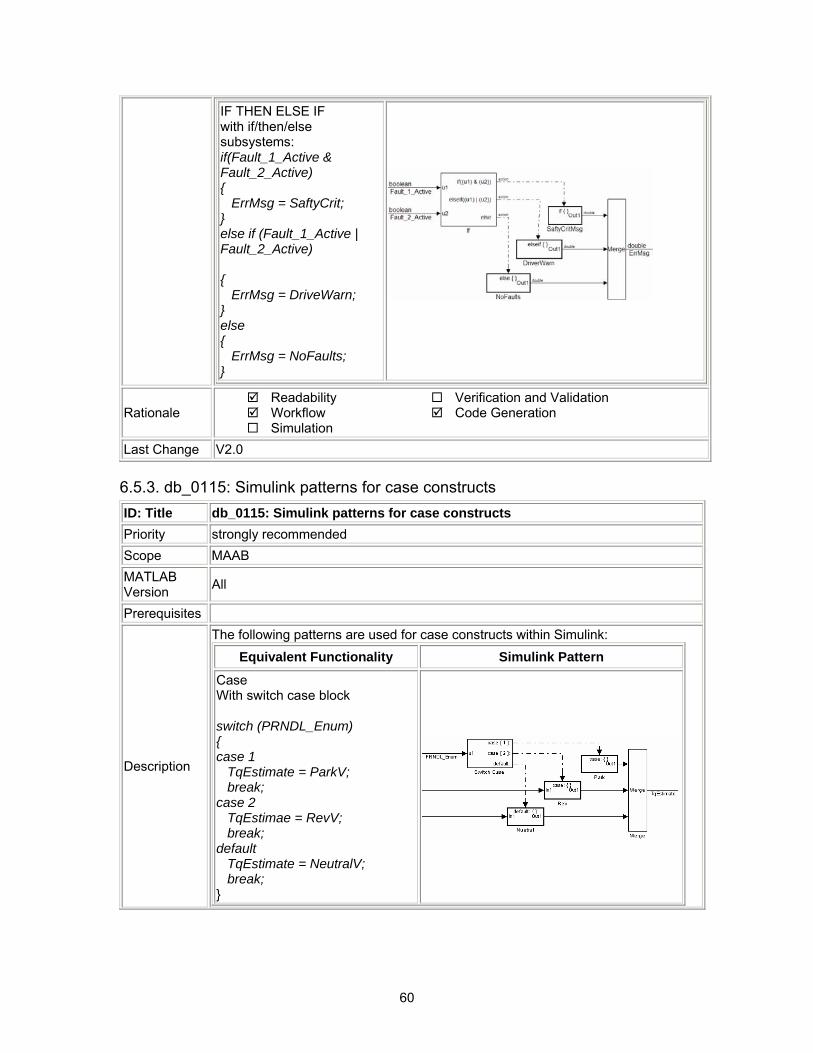
IF THEN ELSE IF with if/then/else subsystems: if(Fault_1_Active & Fault_2_Active) { ErrMsg = SaftyCrit; } else if (Fault_1_Active | Fault_2_Active) { ErrMsg = DriveWarn; } else { ErrMsg = NoFaults; }
Rationale Readability Workflow Simulation
Verification and Validation Code Generation
Last Change V2.0
6.5.3. db_0115: Simulink patterns for case constructs ID: Title db_0115: Simulink patterns for case constructs Priority strongly recommended Scope MAAB MATLAB Version All
Prerequisites
Description
The following patterns are used for case constructs within Simulink:
Equivalent Functionality Simulink Pattern
Case With switch case block switch (PRNDL_Enum) { case 1 TqEstimate = ParkV; break; case 2 TqEstimae = RevV; break; default TqEstimate = NeutralV; break; }
61
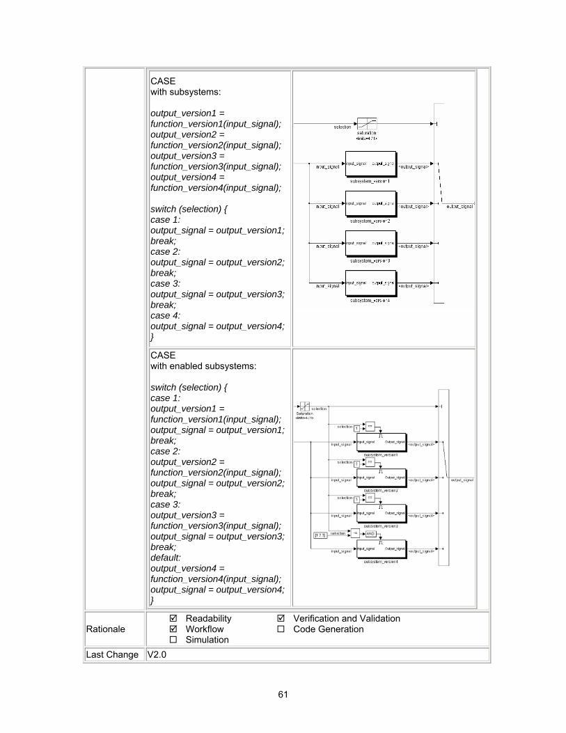
CASE with subsystems: output_version1 = function_version1(input_signal); output_version2 = function_version2(input_signal); output_version3 = function_version3(input_signal); output_version4 = function_version4(input_signal); switch (selection) { case 1: output_signal = output_version1; break; case 2: output_signal = output_version2; break; case 3: output_signal = output_version3; break; case 4: output_signal = output_version4; }
CASE with enabled subsystems: switch (selection) { case 1: output_version1 = function_version1(input_signal); output_signal = output_version1; break; case 2: output_version2 = function_version2(input_signal); output_signal = output_version2; break; case 3: output_version3 = function_version3(input_signal); output_signal = output_version3; break; default: output_version4 = function_version4(input_signal); output_signal = output_version4; }
Rationale Readability Workflow Simulation
Verification and Validation Code Generation
Last Change V2.0
62
6.5.4. db_0116: Simulink patterns for logical constructs with logical blocks ID: Title db_0116: Simulink patterns for logical constructs with logical blocks Priority strongly recommended Scope MAAB MATLAB Version All
Prerequisites
Description
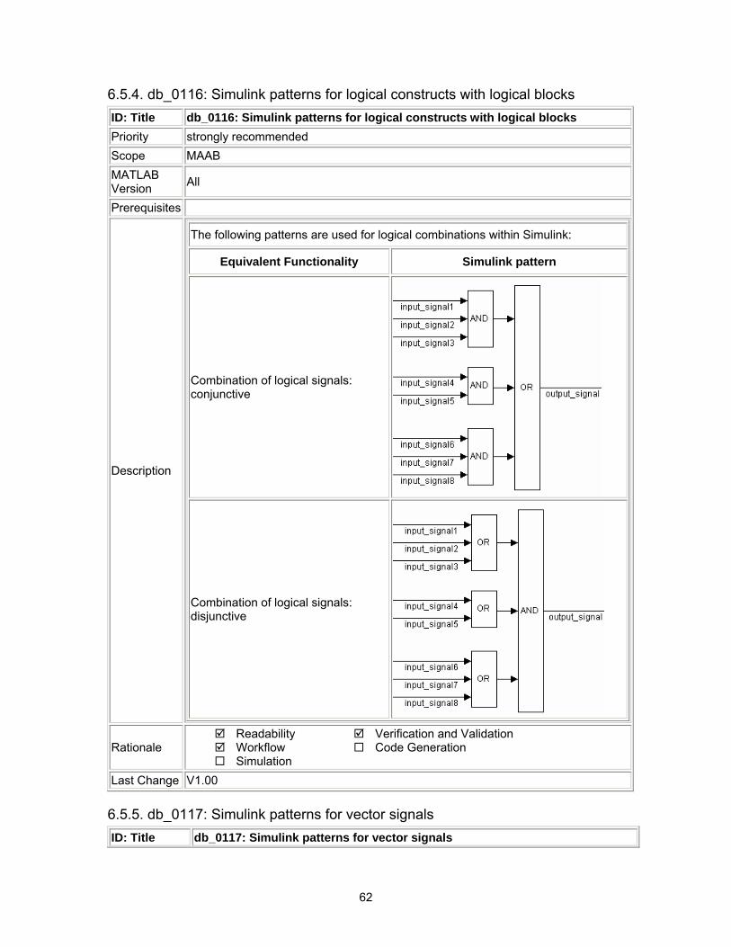
The following patterns are used for logical combinations within Simulink:
Equivalent Functionality Simulink pattern
Combination of logical signals: conjunctive
Combination of logical signals: disjunctive
Rationale Readability Workflow Simulation
Verification and Validation Code Generation
Last Change V1.00
6.5.5. db_0117: Simulink patterns for vector signals ID: Title db_0117: Simulink patterns for vector signals
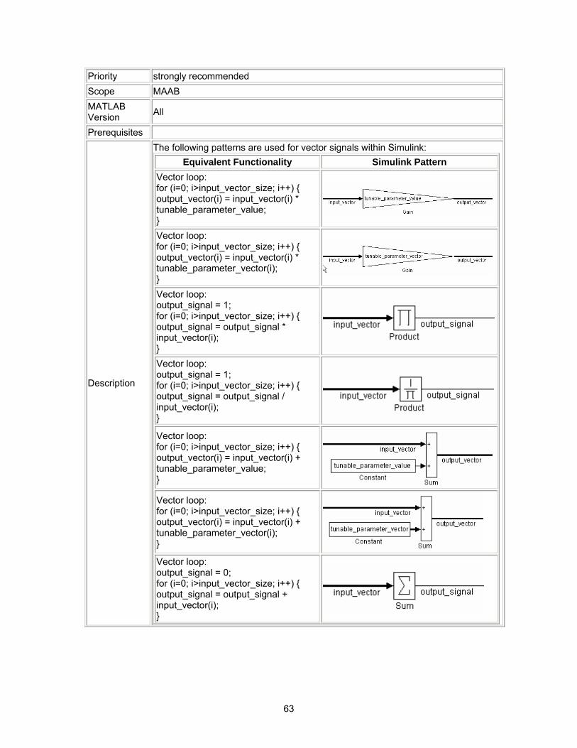
63
Priority strongly recommended Scope MAAB MATLAB Version All
Prerequisites
Description
The following patterns are used for vector signals within Simulink: Equivalent Functionality Simulink Pattern
Vector loop: for (i=0; i>input_vector_size; i++) { output_vector(i) = input_vector(i) * tunable_parameter_value; }
Vector loop: for (i=0; i>input_vector_size; i++) { output_vector(i) = input_vector(i) * tunable_parameter_vector(i); }
Vector loop: output_signal = 1; for (i=0; i>input_vector_size; i++) { output_signal = output_signal * input_vector(i); } Vector loop: output_signal = 1; for (i=0; i>input_vector_size; i++) { output_signal = output_signal / input_vector(i); }
Vector loop: for (i=0; i>input_vector_size; i++) { output_vector(i) = input_vector(i) + tunable_parameter_value; }
Vector loop: for (i=0; i>input_vector_size; i++) { output_vector(i) = input_vector(i) + tunable_parameter_vector(i); } Vector loop: output_signal = 0; for (i=0; i>input_vector_size; i++) { output_signal = output_signal + input_vector(i); }
64
Vector loop: output_signal = 0; for (i=0; i>input_vector_size; i++) { output_signal = output_signal - input_vector(i); }
Minimum or maximum of a signal or a vector over time:
Change event of a signal or a vector:
Rationale Readability Workflow Simulation
Verification and Validation Code Generation
Last Change V1.00
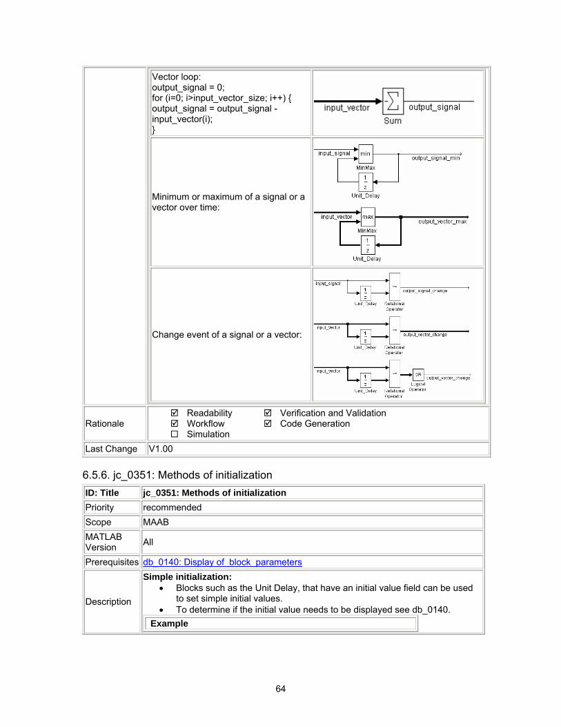
6.5.6. jc_0351: Methods of initialization ID: Title jc_0351: Methods of initialization Priority recommended Scope MAAB MATLAB Version All
Prerequisites db_0140: Display of block parameters
Description
Simple initialization: • Blocks such as the Unit Delay, that have an initial value field can be used
to set simple initial values. • To determine if the initial value needs to be displayed see db_0140.
Example
65
Initialization that requires computation: For complex initializations the following rules hold.
• The initialization should be performed in a separate subsystem. • The initialization subsystem should have a name that indicates that
initialization is performed by the subsystem. Complex initializations can either be done at a local level (Example A) or at a global level (Example B) or a combination.
Example A
Example B
Rationale Readability Workflow Simulation
Verification and Validation Code Generation
Last Change V2.0
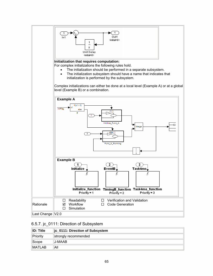
6.5.7. jc_0111: Direction of Subsystem ID: Title jc_0111: Direction of Subsystem Priority strongly recommended Scope J-MAAB MATLAB All
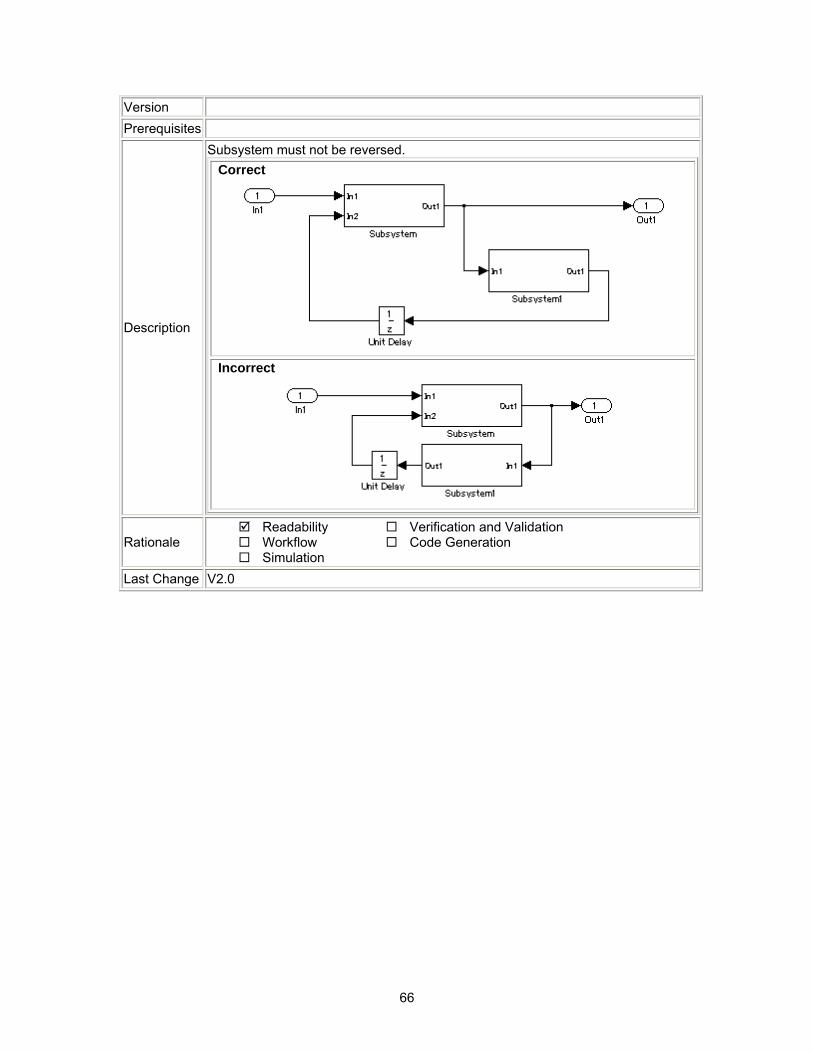
66
Version Prerequisites
Description
Subsystem must not be reversed. Correct
Incorrect
Rationale Readability Workflow Simulation
Verification and Validation Code Generation
Last Change V2.0
67
7.Stateflow
7.1. Chart Appearance 7.1.1. db_0123: Stateflow port names ID: Title db_0123: Stateflow port names Priority strongly recommended Scope MAAB MATLAB Version All
Prerequisites
Description The name of a Stateflow input/output should be the same as the corresponding signal. Exception: Reusable Stateflow blocks may have different port names.
Rationale Readability Workflow Simulation
Verification and Validation Code Generation
Last Change V1.00
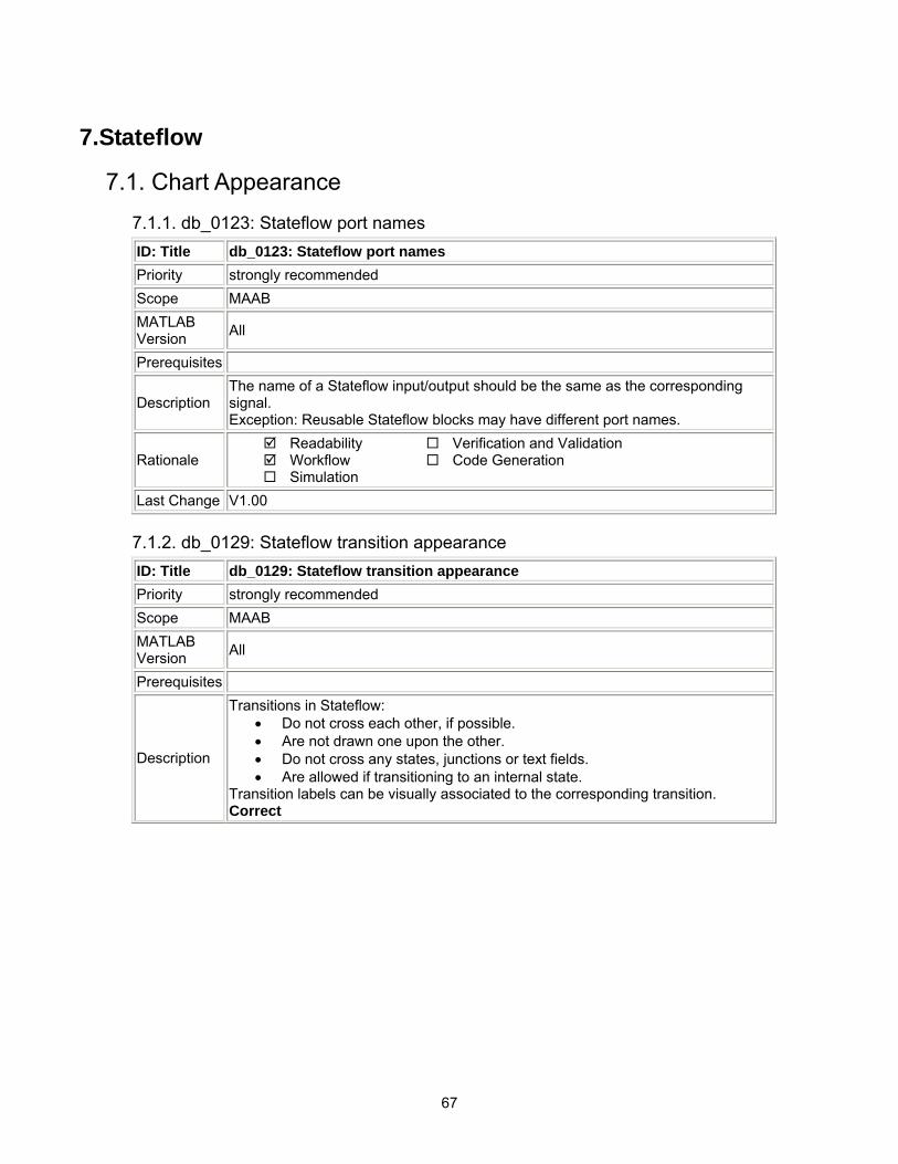
7.1.2. db_0129: Stateflow transition appearance ID: Title db_0129: Stateflow transition appearance Priority strongly recommended Scope MAAB MATLAB Version All
Prerequisites
Description
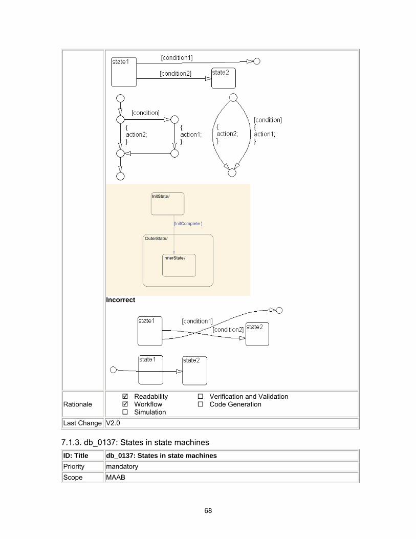
Transitions in Stateflow: • Do not cross each other, if possible. • Are not drawn one upon the other. • Do not cross any states, junctions or text fields. • Are allowed if transitioning to an internal state.
Transition labels can be visually associated to the corresponding transition. Correct
68
Incorrect
Rationale Readability Workflow Simulation
Verification and Validation Code Generation
Last Change V2.0
7.1.3. db_0137: States in state machines ID: Title db_0137: States in state machines Priority mandatory Scope MAAB

69
MATLAB Version All
Prerequisites db_0149: Flowchart patterns for condition actions
Description
In state machines: • There are at least two exclusive states. • A state cannot have only one substate. • The initial state of a hierarchical level with exclusive states is clearly
defined by a default transition.
Rationale Readability Workflow Simulation
Verification and Validation Code Generation
Last Change V2.0
7.1.4. db_0133: Use of patterns for Flowcharts ID: Title db_0133: Use of patterns for Flowcharts Priority strongly recommended Scope MAAB MATLAB Version All
Prerequisites
Description
A Flowchart is built with the help of Flowchart patterns (e.g. IF-THEN-ELSE, FOR LOOP, etc.):
• The data flow is oriented from the top to the bottom. • Patterns are connected with empty transitions.
Rationale Readability Workflow Simulation
Verification and Validation Code Generation
Last Change V1.00
7.1.5. db_0132: Transitions in Flowcharts ID: Title db_0132: Transitions in Flowcharts Priority strongly recommended Scope MAAB MATLAB Version All
Prerequisites
Description
The following rules apply to transitions in Flowcharts: • Conditions are drawn on the horizontal. • Actions are drawn on the vertical. • Loop constructs are intentional exceptions to this rule.
A transition in a Flowchart has a condition, a condition action or an empty transition. Transition with condition:
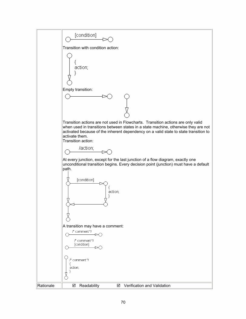
70
Transition with condition action:
Empty transition:
Transition actions are not used in Flowcharts. Transition actions are only valid when used in transitions between states in a state machine, otherwise they are not activated because of the inherent dependency on a valid state to state transition to activate them. Transition action:
At every junction, except for the last junction of a flow diagram, exactly one unconditional transition begins. Every decision point (junction) must have a default path.
A transition may have a comment:
Rationale Readability Verification and Validation
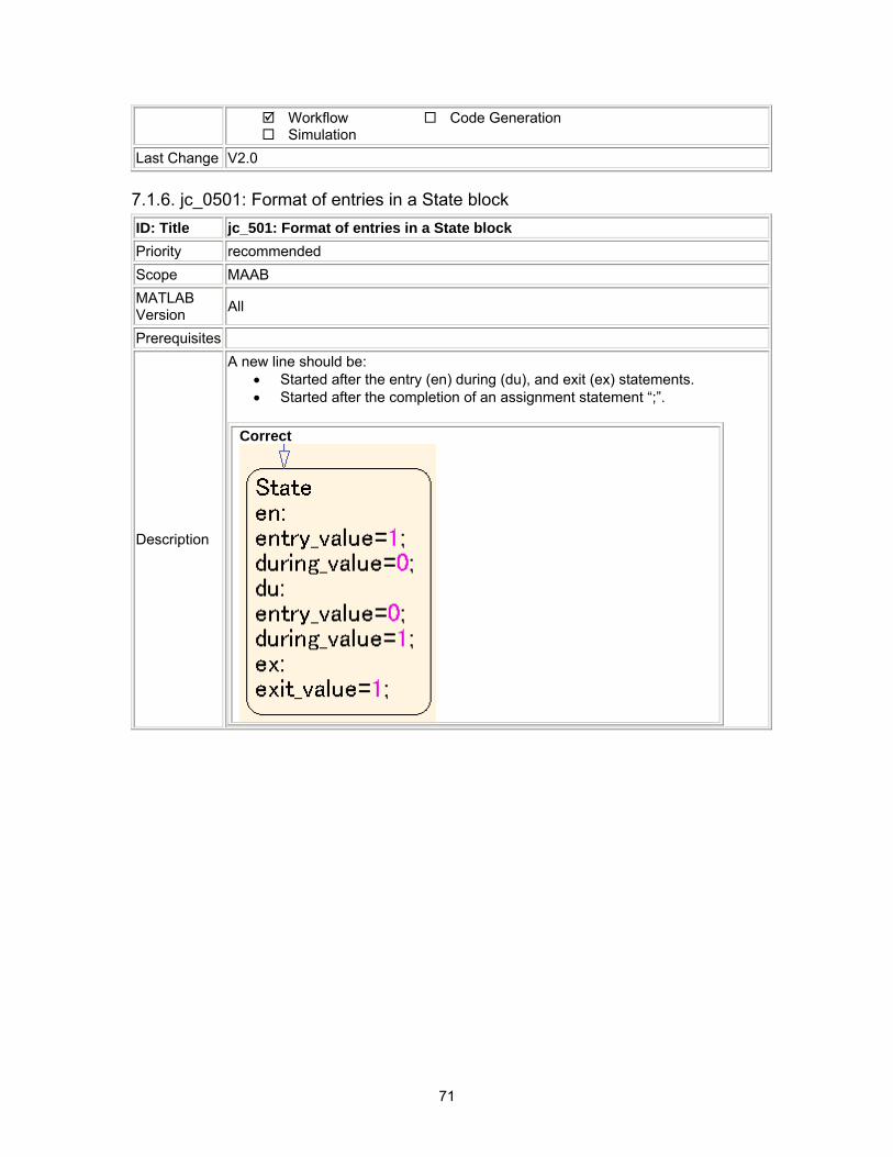
71
Workflow Simulation
Code Generation
Last Change V2.0
7.1.6. jc_0501: Format of entries in a State block ID: Title jc_501: Format of entries in a State block Priority recommended Scope MAAB MATLAB Version All
Prerequisites
Description
A new line should be: • Started after the entry (en) during (du), and exit (ex) statements. • Started after the completion of an assignment statement “;”.
Correct
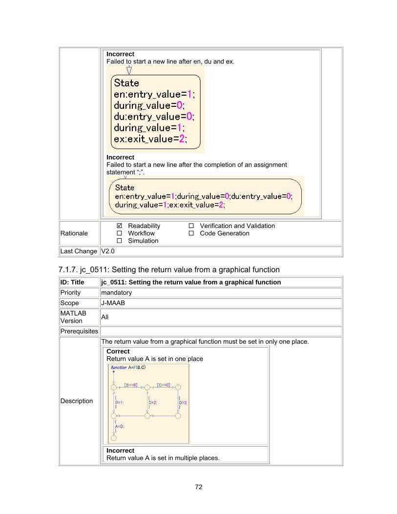
72
Incorrect Failed to start a new line after en, du and ex.
Incorrect Failed to start a new line after the completion of an assignment statement “;”.
Rationale Readability Workflow Simulation
Verification and Validation Code Generation
Last Change V2.0
7.1.7. jc_0511: Setting the return value from a graphical function ID: Title jc_0511: Setting the return value from a graphical function Priority mandatory Scope J-MAAB MATLAB Version All
Prerequisites
Description
The return value from a graphical function must be set in only one place. Correct Return value A is set in one place
Incorrect Return value A is set in multiple places.
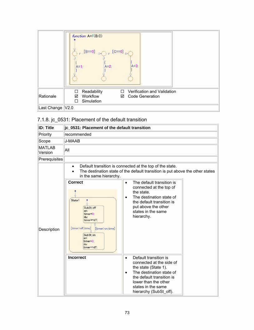
73
Rationale Readability Workflow Simulation
Verification and Validation Code Generation
Last Change V2.0
7.1.8. jc_0531: Placement of the default transition ID: Title jc_0531: Placement of the default transition Priority recommended Scope J-MAAB MATLAB Version All
Prerequisites
Description
• Default transition is connected at the top of the state. • The destination state of the default transition is put above the other states
in the same hierarchy. Correct
• The default transition is connected at the top of the state.
• The destination state of the default transition is put above the other states in the same hierarchy.
Incorrect • Default transition is connected at the side of the state (State 1).
• The destination state of the default transition is lower than the other states in the same hierarchy (SubSt_off).
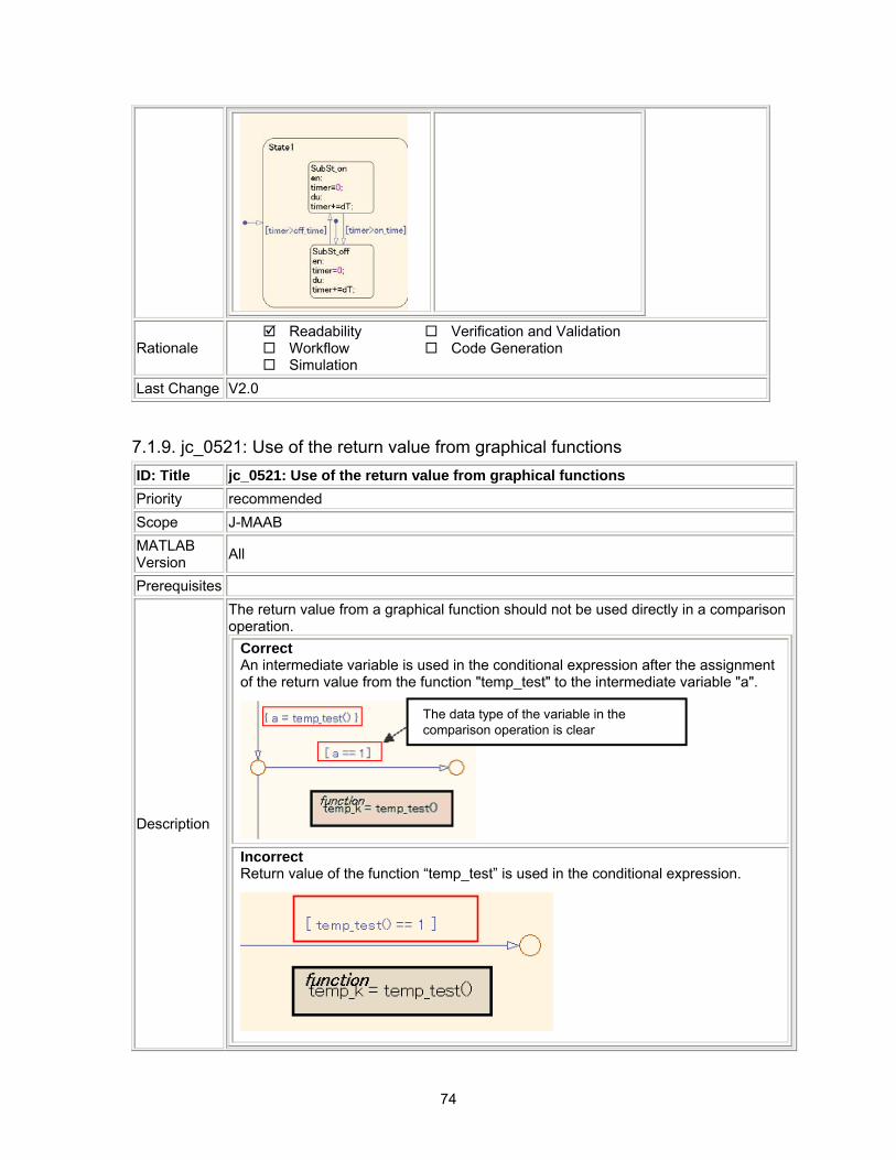
74
Rationale Readability Workflow Simulation
Verification and Validation Code Generation
Last Change V2.0
7.1.9. jc_0521: Use of the return value from graphical functions ID: Title jc_0521: Use of the return value from graphical functions Priority recommended Scope J-MAAB MATLAB Version All
Prerequisites
Description
The return value from a graphical function should not be used directly in a comparison operation.
Correct An intermediate variable is used in the conditional expression after the assignment of the return value from the function "temp_test" to the intermediate variable "a".
The data type of the variable in the comparison operation is clearThe data type of the variable in the comparison operation is clear
Incorrect Return value of the function “temp_test” is used in the conditional expression.
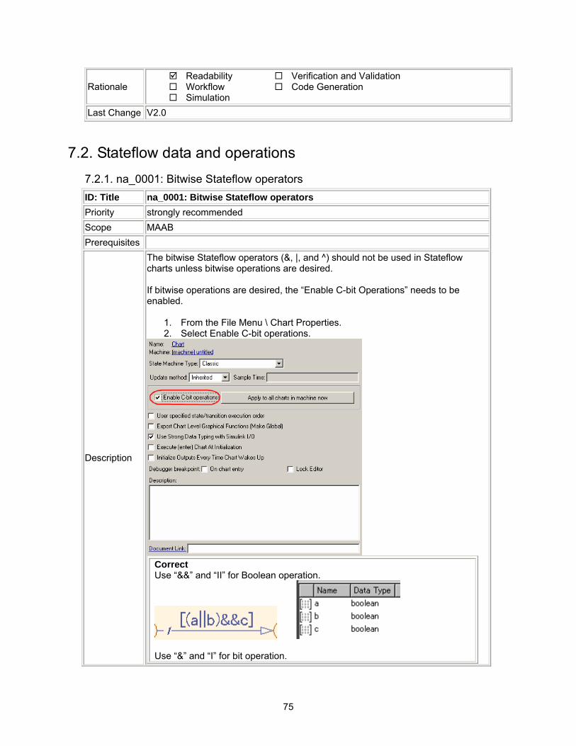
75
Rationale Readability Workflow Simulation
Verification and Validation Code Generation
Last Change V2.0
7.2. Stateflow data and operations 7.2.1. na_0001: Bitwise Stateflow operators ID: Title na_0001: Bitwise Stateflow operators Priority strongly recommended Scope MAAB Prerequisites
Description
The bitwise Stateflow operators (&, |, and ^) should not be used in Stateflow charts unless bitwise operations are desired. If bitwise operations are desired, the “Enable C-bit Operations” needs to be enabled.
1. From the File Menu \ Chart Properties. 2. Select Enable C-bit operations.
Correct Use “&&” and “II” for Boolean operation.
Use “&” and “I” for bit operation.
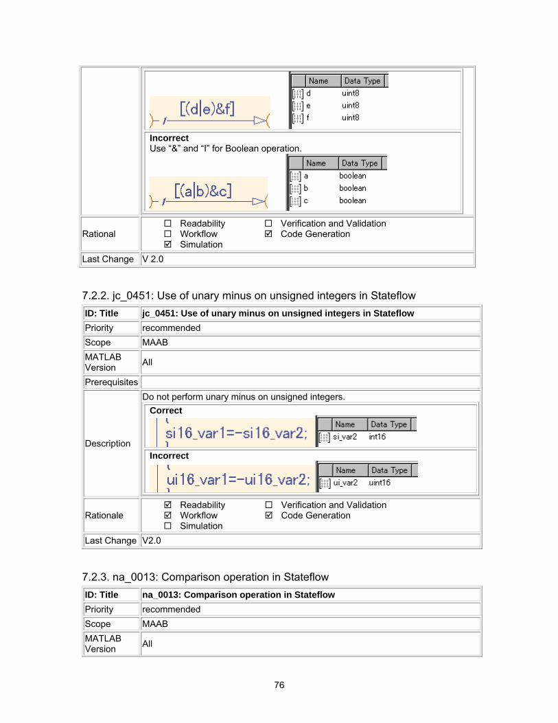
76
Incorrect Use “&” and “I” for Boolean operation.
Rational Readability Workflow Simulation
Verification and Validation Code Generation
Last Change V 2.0
7.2.2. jc_0451: Use of unary minus on unsigned integers in Stateflow ID: Title jc_0451: Use of unary minus on unsigned integers in Stateflow Priority recommended Scope MAAB MATLAB Version All
Prerequisites
Description
Do not perform unary minus on unsigned integers. Correct
Incorrect
Rationale Readability Workflow Simulation
Verification and Validation Code Generation
Last Change V2.0
7.2.3. na_0013: Comparison operation in Stateflow ID: Title na_0013: Comparison operation in Stateflow Priority recommended Scope MAAB MATLAB Version All
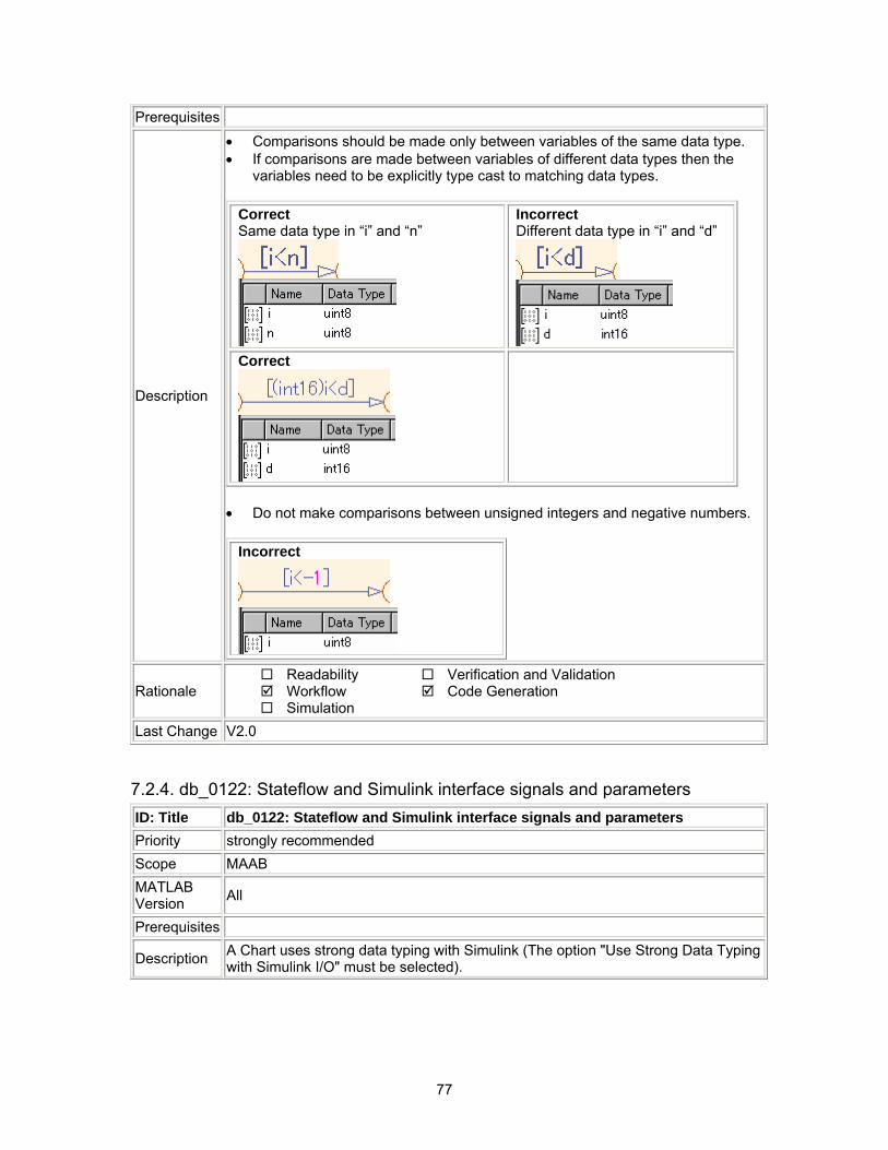
77
Prerequisites
Description
• Comparisons should be made only between variables of the same data type. • If comparisons are made between variables of different data types then the
variables need to be explicitly type cast to matching data types.
Correct Same data type in “i” and “n”
Incorrect Different data type in “i” and “d”
Correct
• Do not make comparisons between unsigned integers and negative numbers.
Incorrect
Rationale Readability Workflow Simulation
Verification and Validation Code Generation
Last Change V2.0
7.2.4. db_0122: Stateflow and Simulink interface signals and parameters ID: Title db_0122: Stateflow and Simulink interface signals and parameters Priority strongly recommended Scope MAAB MATLAB Version All
Prerequisites
Description A Chart uses strong data typing with Simulink (The option "Use Strong Data Typing with Simulink I/O" must be selected).
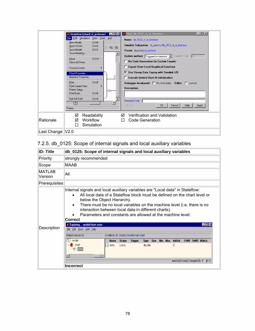
78
Rationale Readability Workflow Simulation
Verification and Validation Code Generation
Last Change V2.0
7.2.5. db_0125: Scope of internal signals and local auxiliary variables ID: Title db_0125: Scope of internal signals and local auxiliary variables Priority strongly recommended Scope MAAB MATLAB Version All
Prerequisites
Description
Internal signals and local auxiliary variables are "Local data" in Stateflow: • All local data of a Stateflow block must be defined on the chart level or
below the Object Hierarchy. • There must be no local variables on the machine level (i.e. there is no
interaction between local data in different charts). • Parameters and constants are allowed at the machine level.
Correct
Incorrect
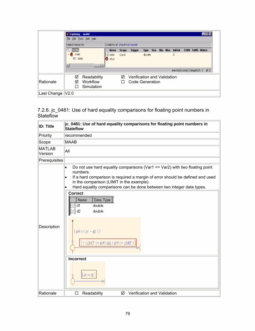
79
Rationale Readability Workflow Simulation
Verification and Validation Code Generation
Last Change V2.0
7.2.6. jc_0481: Use of hard equality comparisons for floating point numbers in Stateflow
ID: Title jc_0481: Use of hard equality comparisons for floating point numbers in Stateflow
Priority recommended Scope MAAB MATLAB Version All
Prerequisites
Description
• Do not use hard equality comparisons (Var1 == Var2) with two floating point numbers.
• If a hard comparison is required a margin of error should be defined and used in the comparison (LIMIT in the example).
• Hard equality comparisons can be done between two integer data types. Correct
Incorrect
Rationale Readability Verification and Validation
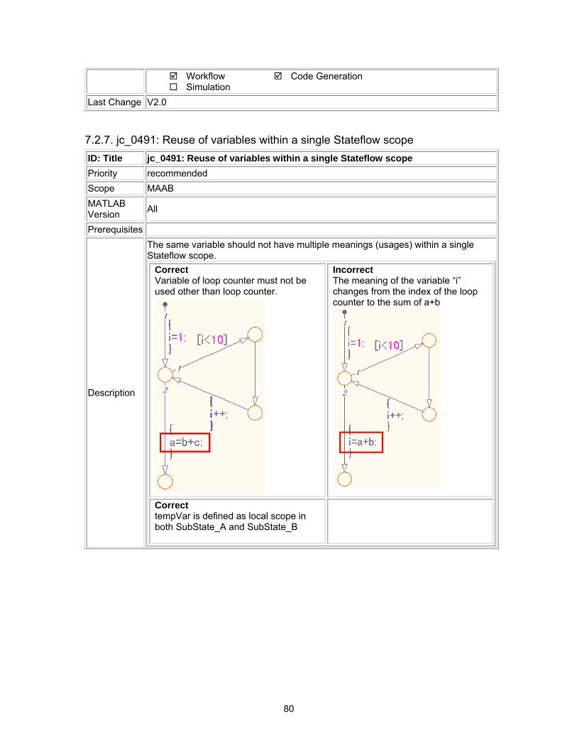
80
Workflow Simulation
Code Generation
Last Change V2.0
7.2.7. jc_0491: Reuse of variables within a single Stateflow scope ID: Title jc_0491: Reuse of variables within a single Stateflow scope Priority recommended Scope MAAB MATLAB Version All
Prerequisites
Description
The same variable should not have multiple meanings (usages) within a single Stateflow scope.
Correct Variable of loop counter must not be used other than loop counter.
Incorrect The meaning of the variable “i” changes from the index of the loop counter to the sum of a+b
Correct tempVar is defined as local scope in both SubState_A and SubState_B
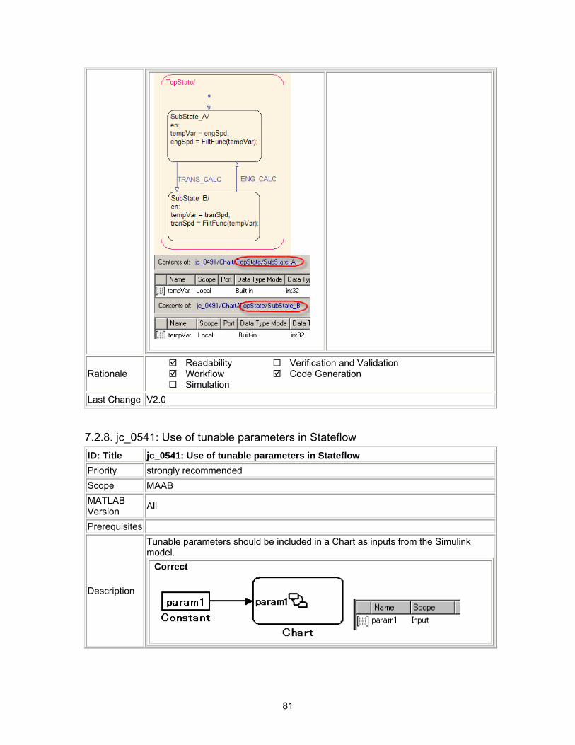
81
Rationale Readability Workflow Simulation
Verification and Validation Code Generation
Last Change V2.0
7.2.8. jc_0541: Use of tunable parameters in Stateflow ID: Title jc_0541: Use of tunable parameters in Stateflow Priority strongly recommended Scope MAAB MATLAB Version All
Prerequisites
Description
Tunable parameters should be included in a Chart as inputs from the Simulink model.
Correct
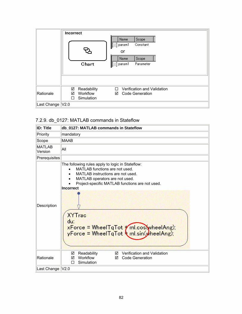
82
Incorrect
もしくはor
Rationale Readability Workflow Simulation
Verification and Validation Code Generation
Last Change V2.0
7.2.9. db_0127: MATLAB commands in Stateflow ID: Title db_0127: MATLAB commands in Stateflow Priority mandatory Scope MAAB MATLAB Version All
Prerequisites
Description
The following rules apply to logic in Stateflow: • MATLAB functions are not used. • MATLAB instructions are not used. • MATLAB operators are not used. • Project-specific MATLAB functions are not used.
Incorrect
Rationale Readability Workflow Simulation
Verification and Validation Code Generation
Last Change V2.0
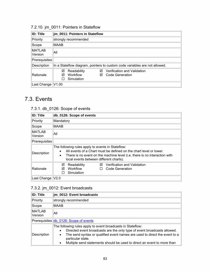
83
7.2.10. jm_0011: Pointers in Stateflow ID: Title jm_0011: Pointers in Stateflow Priority strongly recommended Scope MAAB MATLAB Version All
Prerequisites Description In a Stateflow diagram, pointers to custom code variables are not allowed.
Rationale Readability Workflow Simulation
Verification and Validation Code Generation
Last Change V1.00
7.3. Events 7.3.1. db_0126: Scope of events ID: Title db_0126: Scope of events Priority Mandatory Scope MAAB MATLAB Version All
Prerequisites
Description
The following rules apply to events in Stateflow: • All events of a Chart must be defined on the chart level or lower. • There is no event on the machine level (i.e. there is no interaction with
local events between different charts).
Rationale Readability Workflow Simulation
Verification and Validation Code Generation
Last Change V2.0
7.3.2. jm_0012: Event broadcasts ID: Title jm_0012: Event broadcasts Priority strongly recommended Scope MAAB MATLAB Version All
Prerequisites db_0126: Scope of events
Description
The following rules apply to event broadcasts in Stateflow: • Directed event broadcasts are the only type of event broadcasts allowed. • The send syntax or qualified event names are used to direct the event to a
particular state. • Multiple send statements should be used to direct an event to more than
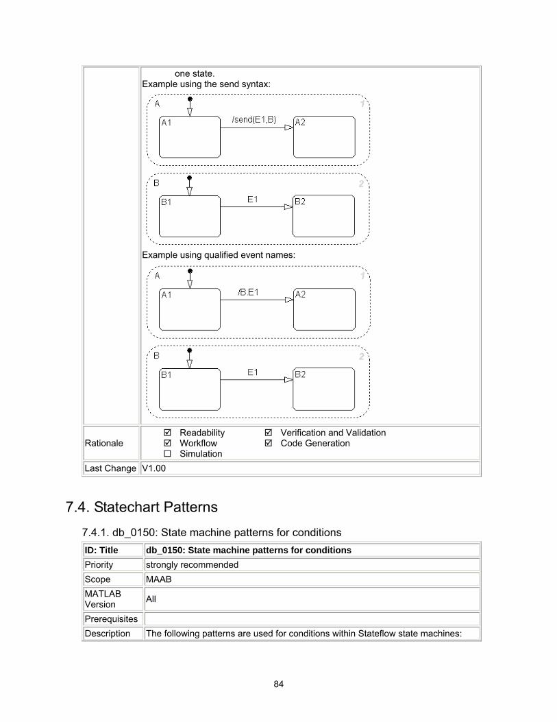
84
one state. Example using the send syntax:
Example using qualified event names:
Rationale Readability Workflow Simulation
Verification and Validation Code Generation
Last Change V1.00
7.4. Statechart Patterns 7.4.1. db_0150: State machine patterns for conditions ID: Title db_0150: State machine patterns for conditions Priority strongly recommended Scope MAAB MATLAB Version All
Prerequisites Description The following patterns are used for conditions within Stateflow state machines:
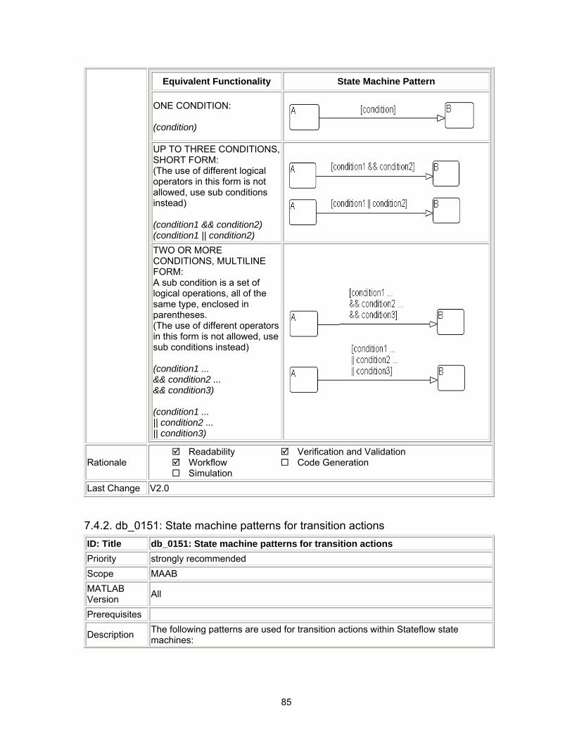
85
Equivalent Functionality State Machine Pattern
ONE CONDITION: (condition)
UP TO THREE CONDITIONS, SHORT FORM: (The use of different logical operators in this form is not allowed, use sub conditions instead) (condition1 && condition2) (condition1 || condition2)
TWO OR MORE CONDITIONS, MULTILINE FORM: A sub condition is a set of logical operations, all of the same type, enclosed in parentheses. (The use of different operators in this form is not allowed, use sub conditions instead) (condition1 ... && condition2 ... && condition3) (condition1 ... || condition2 ... || condition3)
Rationale Readability Workflow Simulation
Verification and Validation Code Generation
Last Change V2.0
7.4.2. db_0151: State machine patterns for transition actions ID: Title db_0151: State machine patterns for transition actions Priority strongly recommended Scope MAAB MATLAB Version All
Prerequisites
Description The following patterns are used for transition actions within Stateflow state machines:
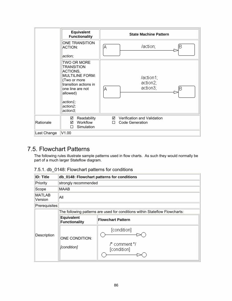
86
Equivalent Functionality State Machine Pattern
ONE TRANSITION ACTION: action;
TWO OR MORE TRANSITION ACTIONS, MULTILINE FORM: (Two or more transition actions in one line are not allowed) action1; action2; action3;
Rationale Readability Workflow Simulation
Verification and Validation Code Generation
Last Change V1.00
7.5. Flowchart Patterns The following rules illustrate sample patterns used in flow charts. As such they would normally be part of a much larger Stateflow diagram.
7.5.1. db_0148: Flowchart patterns for conditions ID: Title db_0148: Flowchart patterns for conditions Priority strongly recommended Scope MAAB MATLAB Version All
Prerequisites
Description
The following patterns are used for conditions within Stateflow Flowcharts: Equivalent Functionality Flowchart Pattern
ONE CONDITION: [condition]
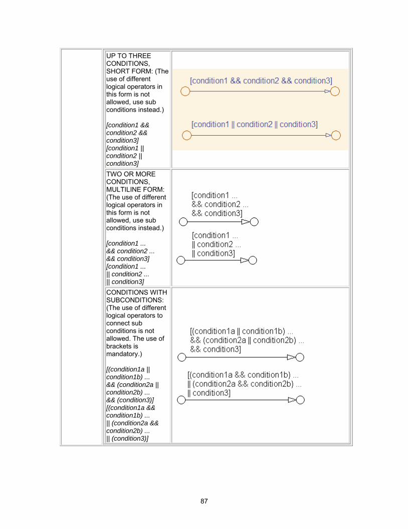
87
UP TO THREE CONDITIONS, SHORT FORM: (The use of different logical operators in this form is not allowed, use sub conditions instead.) [condition1 && condition2 && condition3] [condition1 || condition2 || condition3] TWO OR MORE CONDITIONS, MULTILINE FORM: (The use of different logical operators in this form is not allowed, use sub conditions instead.) [condition1 ... && condition2 ... && condition3] [condition1 ... || condition2 ... || condition3]
CONDITIONS WITH SUBCONDITIONS: (The use of different logical operators to connect sub conditions is not allowed. The use of brackets is mandatory.) [(condition1a || condition1b) ... && (condition2a || condition2b) ... && (condition3)] [(condition1a && condition1b) ... || (condition2a && condition2b) ... || (condition3)]
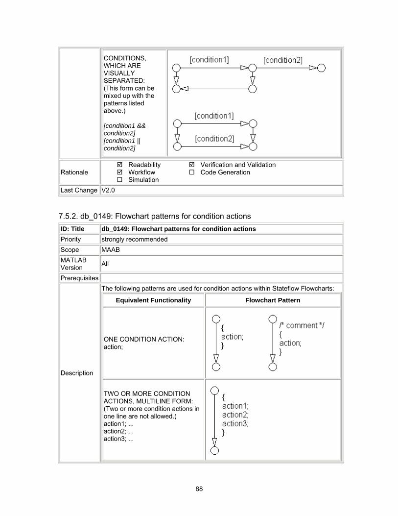
88
CONDITIONS, WHICH ARE VISUALLY SEPARATED: (This form can be mixed up with the patterns listed above.) [condition1 && condition2] [condition1 || condition2]
Rationale Readability Workflow Simulation
Verification and Validation Code Generation
Last Change V2.0
7.5.2. db_0149: Flowchart patterns for condition actions ID: Title db_0149: Flowchart patterns for condition actions Priority strongly recommended Scope MAAB MATLAB Version All
Prerequisites
Description
The following patterns are used for condition actions within Stateflow Flowcharts:
Equivalent Functionality Flowchart Pattern
ONE CONDITION ACTION: action;
TWO OR MORE CONDITION ACTIONS, MULTILINE FORM: (Two or more condition actions in one line are not allowed.) action1; ... action2; ... action3; ...
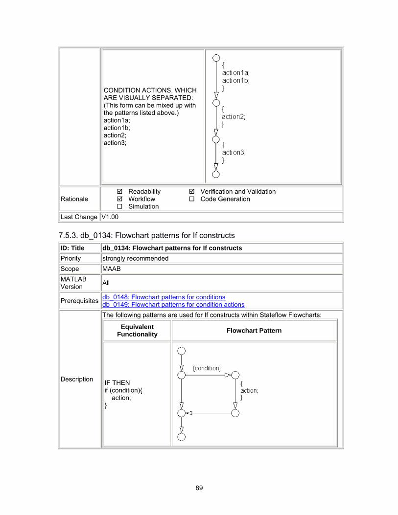
89
CONDITION ACTIONS, WHICH ARE VISUALLY SEPARATED: (This form can be mixed up with the patterns listed above.) action1a; action1b; action2; action3;
Rationale Readability Workflow Simulation
Verification and Validation Code Generation
Last Change V1.00
7.5.3. db_0134: Flowchart patterns for If constructs ID: Title db_0134: Flowchart patterns for If constructs Priority strongly recommended Scope MAAB MATLAB Version All
Prerequisites db_0148: Flowchart patterns for conditions db_0149: Flowchart patterns for condition actions
Description
The following patterns are used for If constructs within Stateflow Flowcharts:
Equivalent Functionality Flowchart Pattern
IF THEN if (condition){ action; }
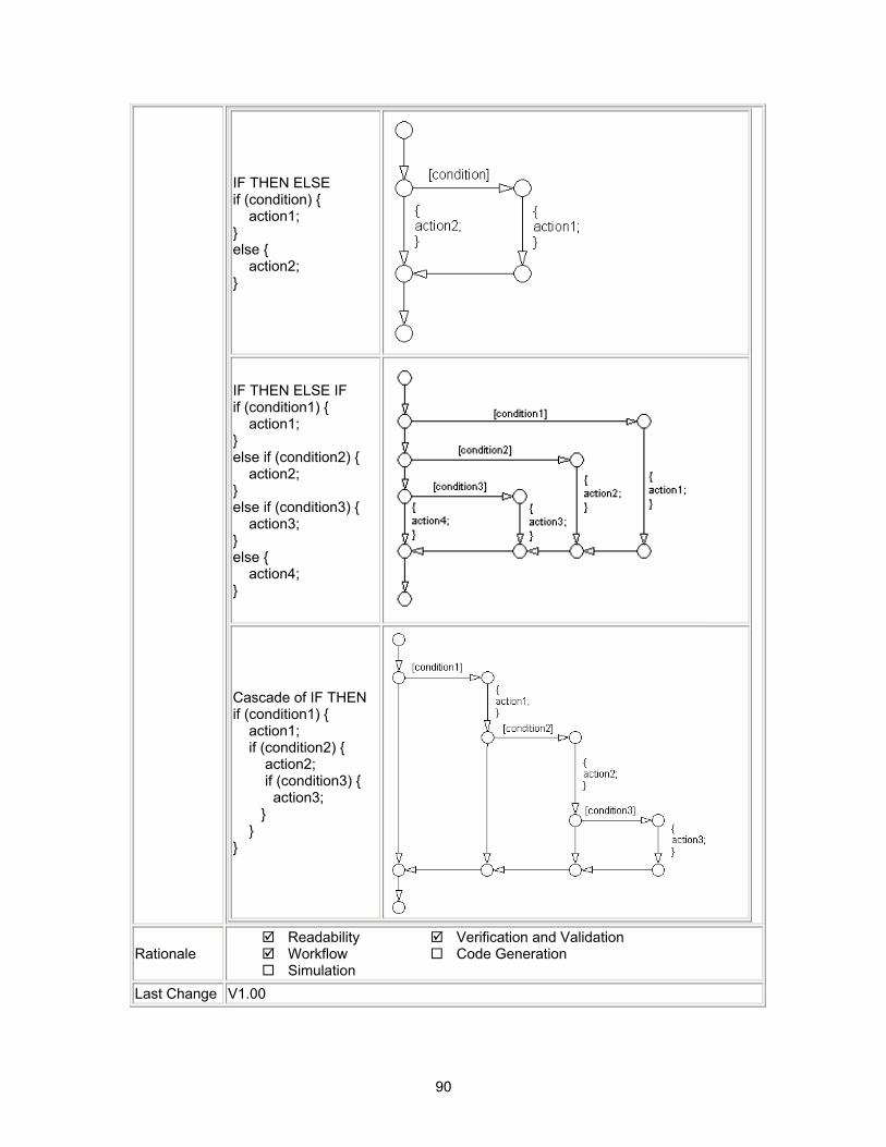
90
IF THEN ELSE if (condition) { action1; } else { action2; }
IF THEN ELSE IF if (condition1) { action1; } else if (condition2) { action2; } else if (condition3) { action3; } else { action4; }
Cascade of IF THEN if (condition1) { action1; if (condition2) { action2; if (condition3) { action3; } } }
Rationale Readability Workflow Simulation
Verification and Validation Code Generation
Last Change V1.00
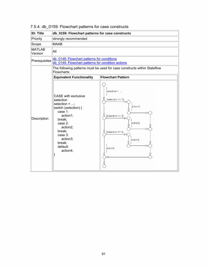
91
7.5.4. db_0159: Flowchart patterns for case constructs ID: Title db_0159: Flowchart patterns for case constructs Priority strongly recommended Scope MAAB MATLAB Version All
Prerequisites db_0148: Flowchart patterns for conditions db_0149: Flowchart patterns for condition actions
Description
The following patterns must be used for case constructs within Stateflow Flowcharts: Equivalent Functionality Flowchart Pattern
CASE with exclusive selection selection = ...; switch (selection) { case 1: action1; break; case 2: action2; break; case 3: action3; break; default: action4; }
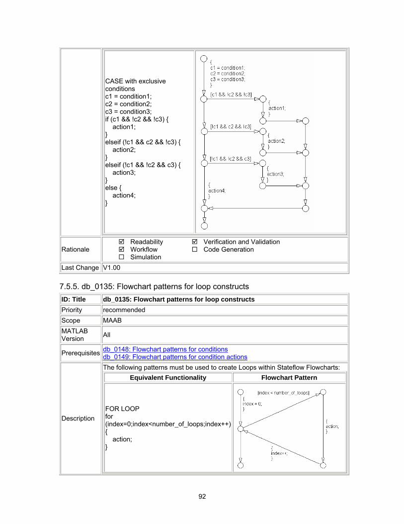
92
CASE with exclusive conditions c1 = condition1; c2 = condition2; c3 = condition3; if (c1 && !c2 && !c3) { action1; } elseif (!c1 && c2 && !c3) { action2; } elseif (!c1 && !c2 && c3) { action3; } else { action4; }
Rationale Readability Workflow Simulation
Verification and Validation Code Generation
Last Change V1.00
7.5.5. db_0135: Flowchart patterns for loop constructs ID: Title db_0135: Flowchart patterns for loop constructs Priority recommended Scope MAAB MATLAB Version All
Prerequisites db_0148: Flowchart patterns for conditions db_0149: Flowchart patterns for condition actions
Description
The following patterns must be used to create Loops within Stateflow Flowcharts: Equivalent Functionality Flowchart Pattern
FOR LOOP for (index=0;index<number_of_loops;index++) { action; }
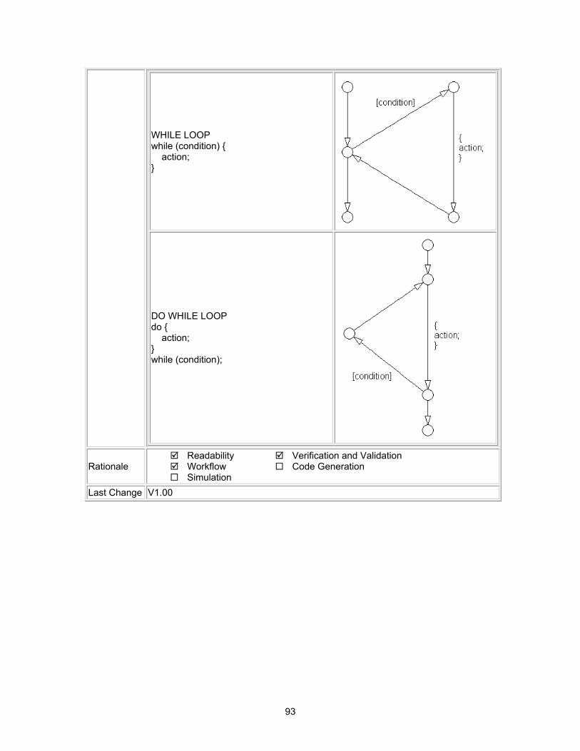
93
WHILE LOOP while (condition) { action; }
DO WHILE LOOP do { action; } while (condition);
Rationale Readability Workflow Simulation
Verification and Validation Code Generation
Last Change V1.00

94
8.Appendix A: Recommendations for Automation Tools These recommendations are intended for any company that develops tools that automate checking of the Style Guidelines. These guidelines were developed by the MathWorks Automotive Advisory Board (MAAB), and it is expected that tool vendors will create tools that check models developed by MathWorks tools against these guidelines. In order to provide the maximum information to potential users of the tools, the MAAB strongly recommends that tool vendors provide a compliance matrix that is easily accessible when the tool is running. This information should be available without a need to purchase the tool first. The compliance matrix should include the following information:
• Version of the guidelines that are checked – shall include the complete title as found on the title page of this document.
• The MAAB Style Guidelines Title and Version document number will be included • Table consisting of the following information for each guideline.
• Guideline ID • Guideline Title • Level of Compliance • Detail
The Guideline ID and Title shall be exactly as included in this document. The Level of Compliance shall be one of the following.
• Correction – The tool checks and automatically or semi-automatically corrects the non-compliance.
• Check – The tool checks and flags non-compliances. It is the developer’s responsibility to make the correction.
• Partial – The tool checks part of the guideline. The detail section should clearly identify what is and what is not checked.
• None – the guideline is not checked by the tool. It is highly recommended that the vendor provide a recommendation of how to manually check any guideline not checked by the tool.

95
9.Appendix B: Guideline Writing The most important things to address when writing a new guideline are that each guideline should be:
• understandable and unambiguous • easy to find • minimal
Guidelines with these characteristics are easier to understand and use. By "understandable and unambiguous" we mean that a guideline's description should be precise, clearly worded, concise and should define an evaluate able property of a model (or part of a model). Use the words "must," "shall," "should," and "may" carefully; they have distinct meanings that are important for model developers and model checkers (human and automated). It is helpful to the reader if the guideline author describes how the conformant state can be reached (e.g. by selecting particular options or clicking a certain button). Examples, counterexamples, pictures, diagrams, and screenshots are also helpful and therefore encouraged. Minimize the allowable exceptions to a guideline; they blur the guideline and make it harder to apply. If a guideline has many allowable exceptions, you may be trying to cover too many characteristics with one guideline - see "minimal" below for some solutions. By "easy to find" we mean that a guideline should have a clear, stable title and be properly located among all the other guidelines. A guideline's title should describe the topic covered but not the specific evaluation criteria. This makes the title less likely to change over time and therefore easier to find. Specific evaluation criteria should be included in the guideline's description. For example, if a guideline addresses the characters allowed in names, the guideline's title should be something like "Allowed characters in names," and the guideline's description should indicate specifically what characters are or are not to be used. If a guideline has prerequisites, they should appear above or before the dependent guideline. (This may not always be possible if the prerequisite is in a different section.) Lastly, by "minimal" we mean that a guideline should address only one model characteristic at a time. Guidelines should be atomic. So, for example, instead of writing a big guideline that addresses error prevention and readability at the same time, make two guidelines – one that addresses error prevention and one that addresses readability. Make one a prerequisite of the other if appropriate. Also, big guidelines are more likely than small guidelines to require compromises for wide acceptance. Big guidelines may therefore end up being weaker, less specific, and less beneficial. Small, focused guidelines will be less likely to change due to compromise and easier to adopt.
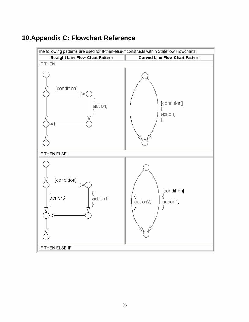
96
10.Appendix C: Flowchart Reference The following patterns are used for If-then-else-if constructs within Stateflow Flowcharts:
Straight Line Flow Chart Pattern Curved Line Flow Chart Pattern IF THEN
IF THEN ELSE
IF THEN ELSE IF
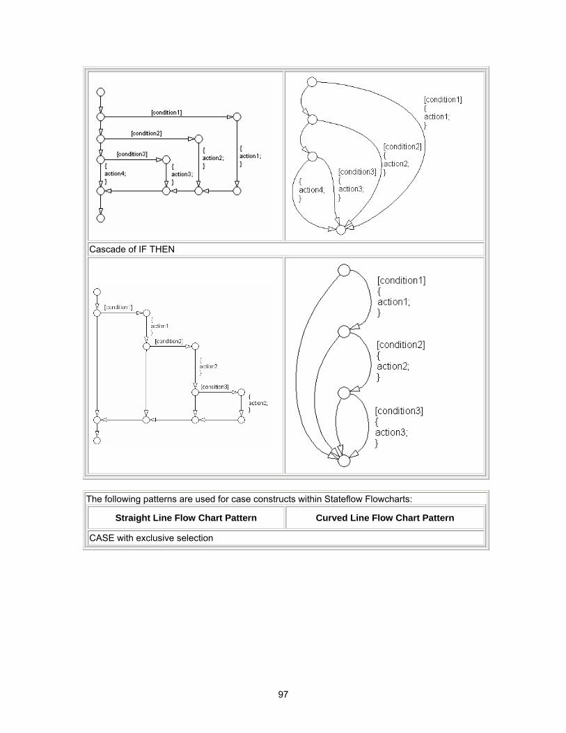
97
Cascade of IF THEN
The following patterns are used for case constructs within Stateflow Flowcharts:
Straight Line Flow Chart Pattern Curved Line Flow Chart Pattern
CASE with exclusive selection
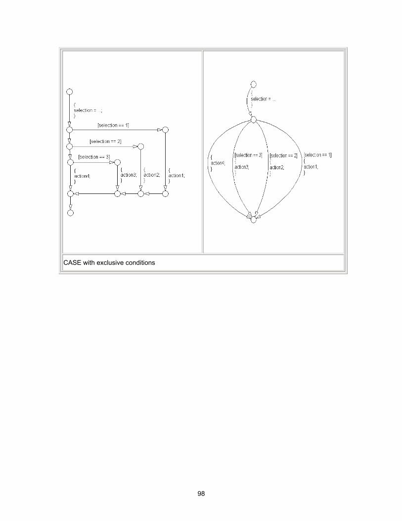
98
CASE with exclusive conditions
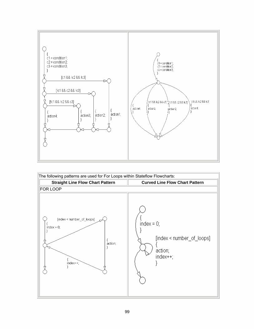
99
The following patterns are used for For Loops within Stateflow Flowcharts:
Straight Line Flow Chart Pattern Curved Line Flow Chart Pattern FOR LOOP
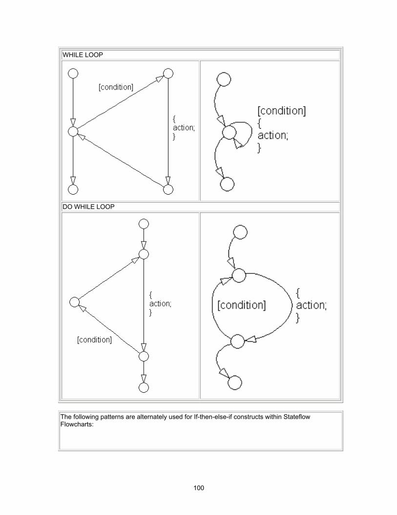
100
WHILE LOOP
DO WHILE LOOP
The following patterns are alternately used for If-then-else-if constructs within Stateflow Flowcharts:
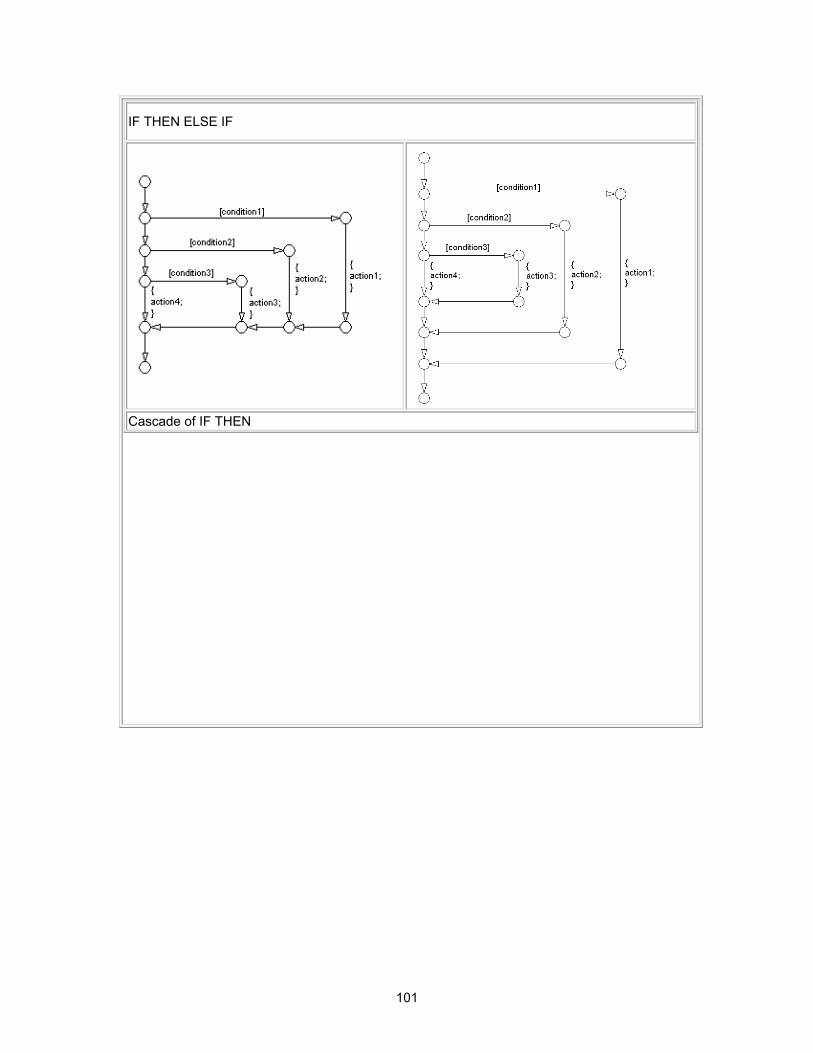
101
IF THEN ELSE IF
Cascade of IF THEN
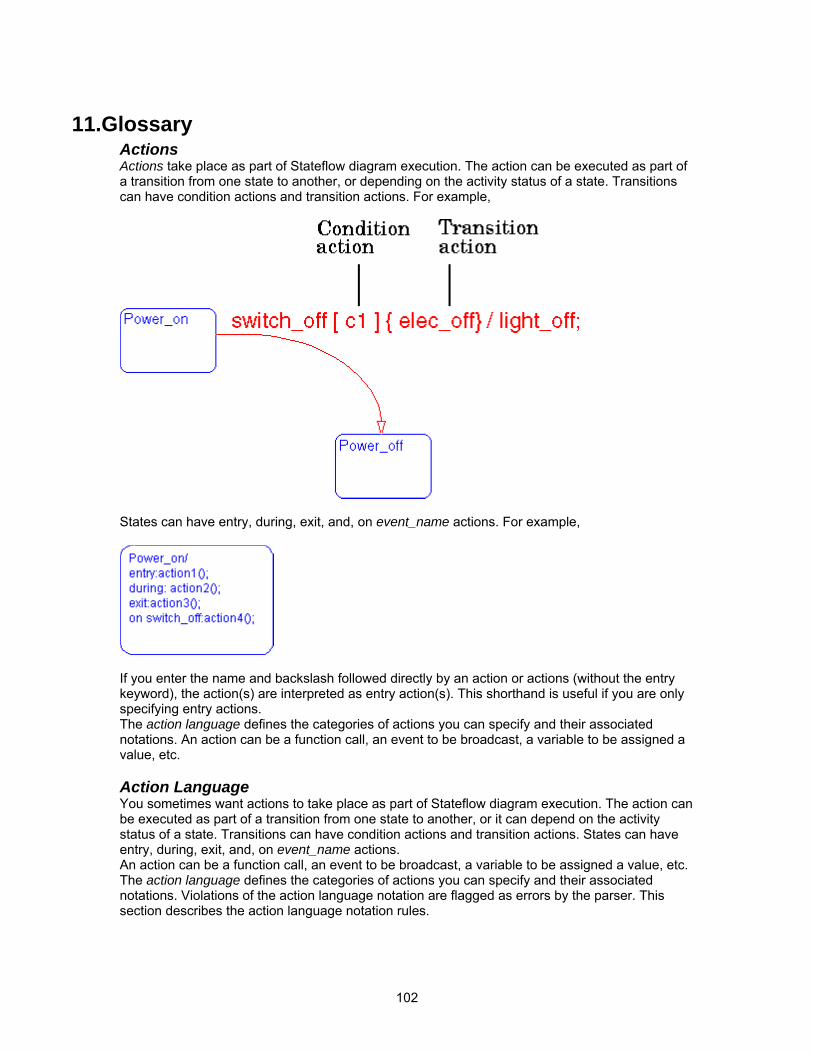
102
11.Glossary Actions Actions take place as part of Stateflow diagram execution. The action can be executed as part of a transition from one state to another, or depending on the activity status of a state. Transitions can have condition actions and transition actions. For example,
States can have entry, during, exit, and, on event_name actions. For example,
If you enter the name and backslash followed directly by an action or actions (without the entry keyword), the action(s) are interpreted as entry action(s). This shorthand is useful if you are only specifying entry actions. The action language defines the categories of actions you can specify and their associated notations. An action can be a function call, an event to be broadcast, a variable to be assigned a value, etc. Action Language You sometimes want actions to take place as part of Stateflow diagram execution. The action can be executed as part of a transition from one state to another, or it can depend on the activity status of a state. Transitions can have condition actions and transition actions. States can have entry, during, exit, and, on event_name actions. An action can be a function call, an event to be broadcast, a variable to be assigned a value, etc. The action language defines the categories of actions you can specify and their associated notations. Violations of the action language notation are flagged as errors by the parser. This section describes the action language notation rules.
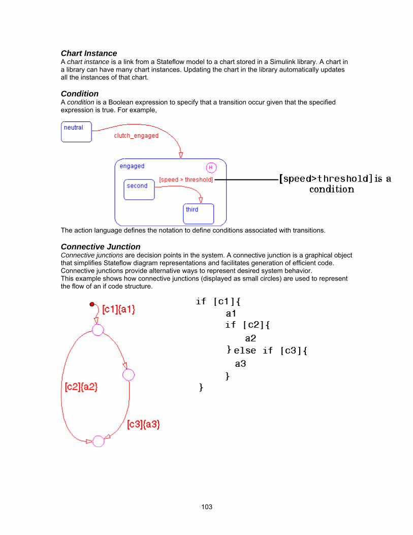
103
Chart Instance A chart instance is a link from a Stateflow model to a chart stored in a Simulink library. A chart in a library can have many chart instances. Updating the chart in the library automatically updates all the instances of that chart. Condition A condition is a Boolean expression to specify that a transition occur given that the specified expression is true. For example,
The action language defines the notation to define conditions associated with transitions. Connective Junction Connective junctions are decision points in the system. A connective junction is a graphical object that simplifies Stateflow diagram representations and facilitates generation of efficient code. Connective junctions provide alternative ways to represent desired system behavior. This example shows how connective junctions (displayed as small circles) are used to represent the flow of an if code structure.

104
Or the equivalent squared style
Name Button Icon
Description
Connective junction
One use of a Connective junction is to handle situations where transitions out of one state into two or more states are taken based on the same event but guarded by different conditions.
Data Data objects store numerical values for reference in the Stateflow diagram. Defining Data A state machine can store and retrieve data that resides internally in its own workspace. It can also access data that resides externally in the Simulink model or application that embeds the state machine. When creating a Stateflow model, you must define any internal or external data referenced by the state machine's actions Data Dictionary The data dictionary is a database where Stateflow diagram information is stored. When you create Stateflow diagram objects, the information about those objects is stored in the data dictionary once you save the Stateflow diagram. Decomposition A state has decomposition when it consists of one or more substates. A Stateflow diagram that contains at least one state also has decomposition. Representing hierarchy necessitates some rules around how states can be grouped in the hierarchy. A superstate has either parallel (AND) or exclusive (OR) decomposition. All substates at a particular level in the hierarchy must be of the same decomposition. Parallel (AND) State Decomposition. Parallel (AND) state decomposition is indicated when states have dashed borders. This representation is appropriate if all states at that same level in the hierarchy are active at the same time. The activity within parallel states is essentially independent. Exclusive (OR) State Decomposition. Exclusive (OR) state decomposition is represented by states with solid borders. Exclusive (OR) decomposition is used to describe system modes that are mutually exclusive. Only one state, at the same level in the hierarchy, can be active at a time.
105
Default Transition Default transitions are primarily used to specify which exclusive (OR) state is to be entered when there is ambiguity among two or more neighboring exclusive (OR) states. For example, default transitions specify which substate of a superstate with exclusive (OR) decomposition the system enters by default in the absence of any other information. Default transitions are also used to specify that a junction should be entered by default. A default transition is represented by selecting the default transition object from the toolbar and then dropping it to attach to a destination object. The default transition object is a transition with a destination but no source object.
Name Button Icon
Description
Default transition
Use a Default transition to indicate, when entering this level in the hierarchy, which state becomes active by default.
Events Events drive the Stateflow diagram execution. All events that affect the Stateflow diagram must be defined. The occurrence of an event causes the status of the states in the Stateflow diagram to be evaluated. The broadcast of an event can trigger a transition to occur and/or can trigger an action to be executed. Events are broadcast in a top-down manner starting from the event's parent in the hierarchy. Finite State Machine A finite state machine (FSM) is a representation of an event-driven system. FSMs are also used to describe reactive systems. In an event-driven or reactive system, the system transitions from one mode or state, to another prescribed mode or state, provided that the condition defining the change is true. Flow Graph A flow graph is the set of Flowcharts that start from a transition segment that, in turn, starts from a state or a default transition segment. Flowchart (also known as Flow Path) A Flowchart is an ordered sequence of transition segments and junctions where each succeeding segment starts on the junction that terminated the previous segment. Flow Subgraph A flow subgraph is the set of Flowcharts that start on the same transition segment. Hierarchy Hierarchy enables you to organize complex systems by placing states within other higher-level states. A hierarchical design usually reduces the number of transitions and produces neat, more manageable diagrams. History Junction A History Junction provides the means to specify the destination substate of a transition based on historical information. If a superstate has a History Junction, the transition to the destination substate is defined to be the substate that was most recently visited. The History Junction applies to the level of the hierarchy in which it appears.
Name Button Icon
Description

106
History Junction
Use a History Junction to indicate, when entering this level in the hierarchy, that the last state that was active becomes the next state to be active.
Inner Transitions An inner transition is a transition that does not exit the source state. Inner transitions are most powerful when defined for superstates with XOR decomposition. Use of inner transitions can greatly simplify a Stateflow diagram. Library Link A library link is a link to a chart that is stored in a library model in a Simulink block library. Library Model A Stateflow library model is a Stateflow model that is stored in a Simulink library. You can include charts from a library in your model by copying them. When you copy a chart from a library into your model, Stateflow does not physically include the chart in your model. Instead, it creates a link to the library chart. You can create multiple links to a single chart. Each link is called a chart instance. When you include a chart from a library in your model, you also include its state machine. Thus, a Stateflow model that includes links to library charts has multiple state machines. When Stateflow simulates a model that includes charts from a library model, it includes all charts from the library model even if there are links to only some of its models. However, when Stateflow generates a stand-alone or Real-Time Workshop® target, it includes only those charts for which there are links. A model that includes links to a library model can be simulated only if all charts in the library model are free of parse and compile errors. Machine A machine is the collection of all Stateflow blocks defined by a Simulink model exclusive of chart instances (library links). If a model includes any library links, it also includes the state machines defined by the models from which the links originate. Nonvirtual Block Blocks that perform a calculation; such as a Gain block. Notation A notation defines a set of objects and the rules that govern the relationships between those objects. Stateflow notation provides a common language to communicate the design information conveyed by a Stateflow diagram. Stateflow notation consists of: • A set of graphical objects • A set of nongraphical text-based objects • Defined relationships between those objects Parallelism A system with parallelism can have two or more states that can be active at the same time. The activity of parallel states is essentially independent. Parallelism is represented with a parallel (AND) state decomposition. Real-Time System A system that uses actual hardware to implement algorithms, for example, digital signal processing or control applications.
107
Real-Time Workshop® Real-Time Workshop is an automatic C language code generator for Simulink. It produces C code directly from Simulink block diagram models and automatically builds programs that can be run in real-time in a variety of environments. Real-Time Workshop Target An executable built from code generated by Real-Time Workshop S-Function A customized Simulink block written in C or M-Code. C-code S-Functions can be inlined in Real-Time Workshop. When using Simulink together with Stateflow for simulation, Stateflow generates an S-Function (MEX-file) for each Stateflow machine to support model simulation. This generated code is a simulation target and is called the S-Fun target within Stateflow. Signal propagation Process used by Simulink to determine attributes of signals and blocks, such as data types, labels, sample time, dimensionality, and so on, that are determined by connectivity Signal source The signal source is the block of origin for a signal. The signal source may or may not be the true source Simulink Simulink is a software package for modeling, simulating, and analyzing dynamic systems. It supports linear and nonlinear systems, modeled in continuous time, sampled time, or a hybrid of the two. Systems can also be multi-rate, i.e., have different parts that are sampled or updated at different rates. It allows you to represent systems as block diagrams that you build using your mouse to connect blocks and your keyboard to edit block parameters. Stateflow is part of this environment. The Stateflow block is a masked Simulink model. Stateflow builds an S-Function that corresponds to each Stateflow machine. This S-Function is the agent Simulink interacts with for simulation and analysis. The control behavior that Stateflow models complements the algorithmic behavior modeled in Simulink block diagrams. By incorporating Stateflow diagrams into Simulink models, you can add event-driven behavior to Simulink simulations. You create models that represent both data and control flow by combining Stateflow blocks with the standard Simulink blockset. These combined models are simulated using Simulink. State A state describes a mode of a reactive system. A reactive system has many possible states. States in a Stateflow diagram represent these modes. The activity or inactivity of the states dynamically changes based on events and conditions. Every state has hierarchy. In a Stateflow diagram consisting of a single state, that state's parent is the Stateflow diagram itself. A state also has history that applies to its level of hierarchy in the Stateflow diagram. States can have actions that are executed in a sequence based upon action type. The action types are: entry, during, exit, or on event_name actions.
Name Button Icon Description
State
Use a state to depict a mode of the system.
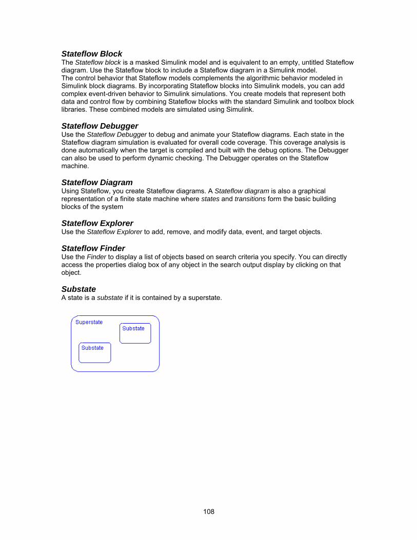
108
Stateflow Block The Stateflow block is a masked Simulink model and is equivalent to an empty, untitled Stateflow diagram. Use the Stateflow block to include a Stateflow diagram in a Simulink model. The control behavior that Stateflow models complements the algorithmic behavior modeled in Simulink block diagrams. By incorporating Stateflow blocks into Simulink models, you can add complex event-driven behavior to Simulink simulations. You create models that represent both data and control flow by combining Stateflow blocks with the standard Simulink and toolbox block libraries. These combined models are simulated using Simulink. Stateflow Debugger Use the Stateflow Debugger to debug and animate your Stateflow diagrams. Each state in the Stateflow diagram simulation is evaluated for overall code coverage. This coverage analysis is done automatically when the target is compiled and built with the debug options. The Debugger can also be used to perform dynamic checking. The Debugger operates on the Stateflow machine. Stateflow Diagram Using Stateflow, you create Stateflow diagrams. A Stateflow diagram is also a graphical representation of a finite state machine where states and transitions form the basic building blocks of the system Stateflow Explorer Use the Stateflow Explorer to add, remove, and modify data, event, and target objects. Stateflow Finder Use the Finder to display a list of objects based on search criteria you specify. You can directly access the properties dialog box of any object in the search output display by clicking on that object. Substate A state is a substate if it is contained by a superstate.
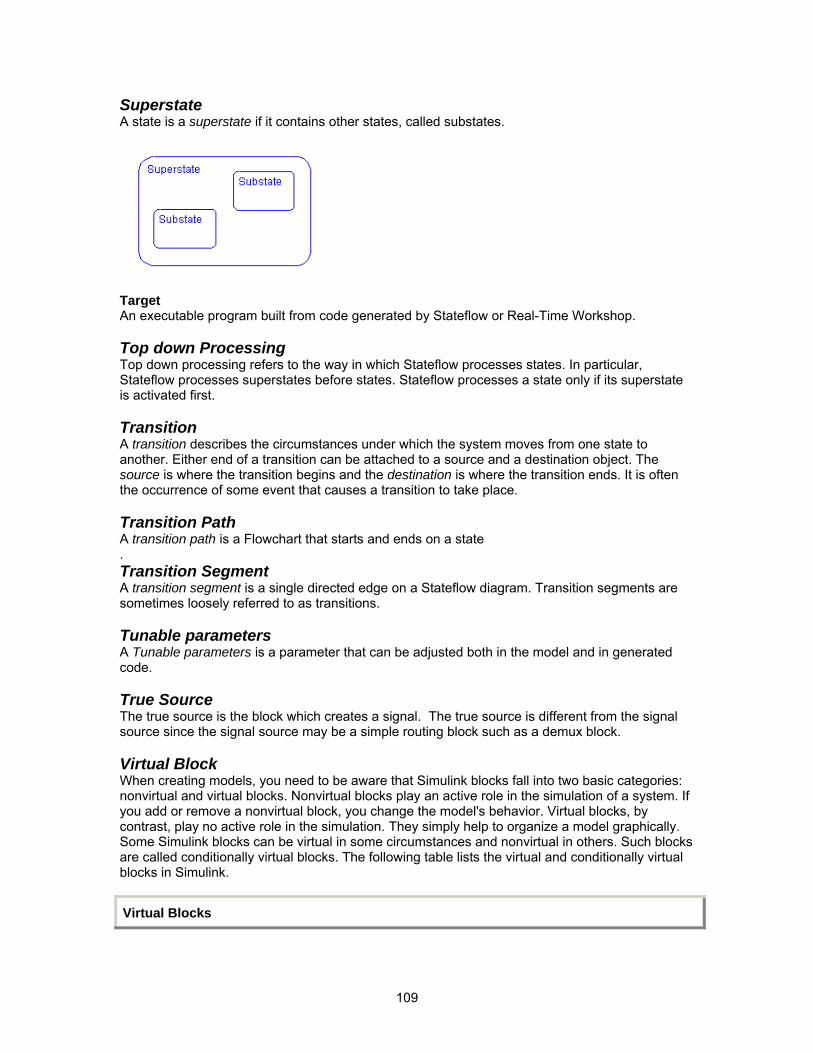
109
Superstate A state is a superstate if it contains other states, called substates.
Target An executable program built from code generated by Stateflow or Real-Time Workshop. Top down Processing Top down processing refers to the way in which Stateflow processes states. In particular, Stateflow processes superstates before states. Stateflow processes a state only if its superstate is activated first. Transition A transition describes the circumstances under which the system moves from one state to another. Either end of a transition can be attached to a source and a destination object. The source is where the transition begins and the destination is where the transition ends. It is often the occurrence of some event that causes a transition to take place. Transition Path A transition path is a Flowchart that starts and ends on a state . Transition Segment A transition segment is a single directed edge on a Stateflow diagram. Transition segments are sometimes loosely referred to as transitions. Tunable parameters A Tunable parameters is a parameter that can be adjusted both in the model and in generated code. True Source The true source is the block which creates a signal. The true source is different from the signal source since the signal source may be a simple routing block such as a demux block. Virtual Block When creating models, you need to be aware that Simulink blocks fall into two basic categories: nonvirtual and virtual blocks. Nonvirtual blocks play an active role in the simulation of a system. If you add or remove a nonvirtual block, you change the model's behavior. Virtual blocks, by contrast, play no active role in the simulation. They simply help to organize a model graphically. Some Simulink blocks can be virtual in some circumstances and nonvirtual in others. Such blocks are called conditionally virtual blocks. The following table lists the virtual and conditionally virtual blocks in Simulink.
Virtual Blocks
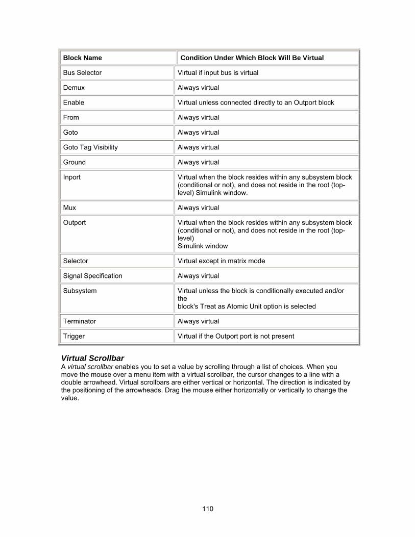
110
Block Name Condition Under Which Block Will Be Virtual
Bus Selector Virtual if input bus is virtual
Demux Always virtual
Enable Virtual unless connected directly to an Outport block
From Always virtual
Goto Always virtual
Goto Tag Visibility Always virtual
Ground Always virtual
Inport Virtual when the block resides within any subsystem block (conditional or not), and does not reside in the root (top-level) Simulink window.
Mux Always virtual
Outport Virtual when the block resides within any subsystem block (conditional or not), and does not reside in the root (top-level) Simulink window
Selector Virtual except in matrix mode
Signal Specification Always virtual
Subsystem Virtual unless the block is conditionally executed and/or the block's Treat as Atomic Unit option is selected
Terminator Always virtual
Trigger Virtual if the Outport port is not present
Virtual Scrollbar A virtual scrollbar enables you to set a value by scrolling through a list of choices. When you move the mouse over a menu item with a virtual scrollbar, the cursor changes to a line with a double arrowhead. Virtual scrollbars are either vertical or horizontal. The direction is indicated by the positioning of the arrowheads. Drag the mouse either horizontally or vertically to change the value.


![Untitled-1 [3fee7a1sld751eqrjr3a035t-wpengine.netdna-ssl.com] · Matlab modeling Technology evaluation GUI Software Development Algorithm & Image processing Embedded SW, FPGA, & LocHW](https://img.pdfslide.us/doc/110x75/5f64e44def368b075d5cfa65/untitled-1-3fee7a1sld751eqrjr3a035t-matlab-modeling-technology-evaluation-gui.jpg)