Embed Size (px)
Citation preview
Contribution to GMGW‐1
• RENAUD Thomas• ONERA – The French Aerospace Lab• PID 05
1st Geometry and Mesh Generation WorkshopDenver, CO June 3‐4, 2017
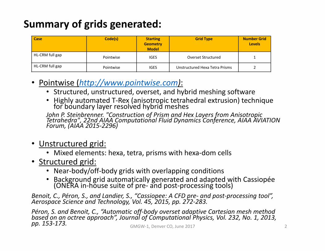
Summary of grids generated:Case Code(s) Starting
Geometry Model
Grid Type Number Grid Levels
HL‐CRM full gap Pointwise IGES Overset Structured 1
HL‐CRM full gap Pointwise IGES Unstructured Hexa Tetra Prisms 2
GMGW‐1, Denver CO, June 2017 2
• Pointwise (http://www.pointwise.com):• Structured, unstructured, overset, and hybrid meshing software• Highly automated T‐Rex (anisotropic tetrahedral extrusion) technique for boundary layer resolved hybrid meshes
John P. Steinbrenner. "Construction of Prism and Hex Layers from Anisotropic Tetrahedra", 22nd AIAA Computational Fluid Dynamics Conference, AIAA AVIATION Forum, (AIAA 2015‐2296)
• Unstructured grid:• Mixed elements: hexa, tetra, prisms with hexa‐dom cells
• Structured grid:• Near‐body/off‐body grids with overlapping conditions• Background grid automatically generated and adapted with Cassiopée(ONERA in‐house suite of pre‐ and post‐processing tools)
Benoit, C., Péron, S., and Landier, S., “Cassiopee: A CFD pre‐ and post‐processing tool”, Aerospace Science and Technology, Vol. 45, 2015, pp. 272‐283.Péron, S. and Benoit, C., “Automatic off‐body overset adaptive Cartesian mesh method based on an octree approach”, Journal of Computational Physics, Vol. 232, No. 1, 2013, pp. 153‐173.
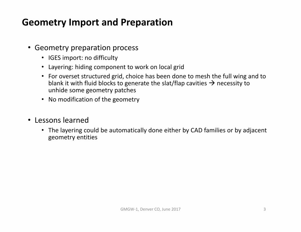
Geometry Import and Preparation
GMGW‐1, Denver CO, June 2017 3
• Geometry preparation process• IGES import: no difficulty• Layering: hiding component to work on local grid• For overset structured grid, choice has been done to mesh the full wing and to
blank it with fluid blocks to generate the slat/flap cavities necessity to unhide some geometry patches
• No modification of the geometry
• Lessons learned• The layering could be automatically done either by CAD families or by adjacent
geometry entities

Mesh Generation (unstructured)
GMGW‐1, Denver CO, June 2017 4
• Mesh generation process• Process flow:
• Automatic edges creation, merged within tolerance. Only characteristic edges are kept.• Surface meshes: structured grids are mainly done on intrados/extrados. Either surfaces are
meshed with quad‐dominant unstructured grid and T‐Rex method to keep a smooth cell size ratio.
• Volume mesh: with BL imposed parameters (no first uniform layers possible), T‐Rex method for the BL (hexa/prisms cells)
• Control of resolution: manual input for edges boundaries, imposed maximum cell size on surfaces and a smooth volume cell size decay (0.95)
• Mesh export file formats: CGNS
• Difficulties encountered• First uniform BLs not possible with T‐Rex method (uniform extrusion+T‐Rex
creates large cell size ratios)• Some difficulties to respect a smooth cell size ratio with multiple adjacent T‐Rex

Mesh Generation (unstructured)
GMGW‐1, Denver CO, June 2017 5
• Difficulties encountered• Volume mesh generation crashed in the wing flaps cavity some iterations to
solve this issue but finally I needed to coarsen the wing cavity trailing edges to perform the volume grid
• Lessons learned• Volume mesh generation can be quite long… and eventually not work
optimization possible?• More information of reasons of crash (representation of the issuing cells and its
adjacent cells)• Local smoothing or improving of cells shapes could be useful
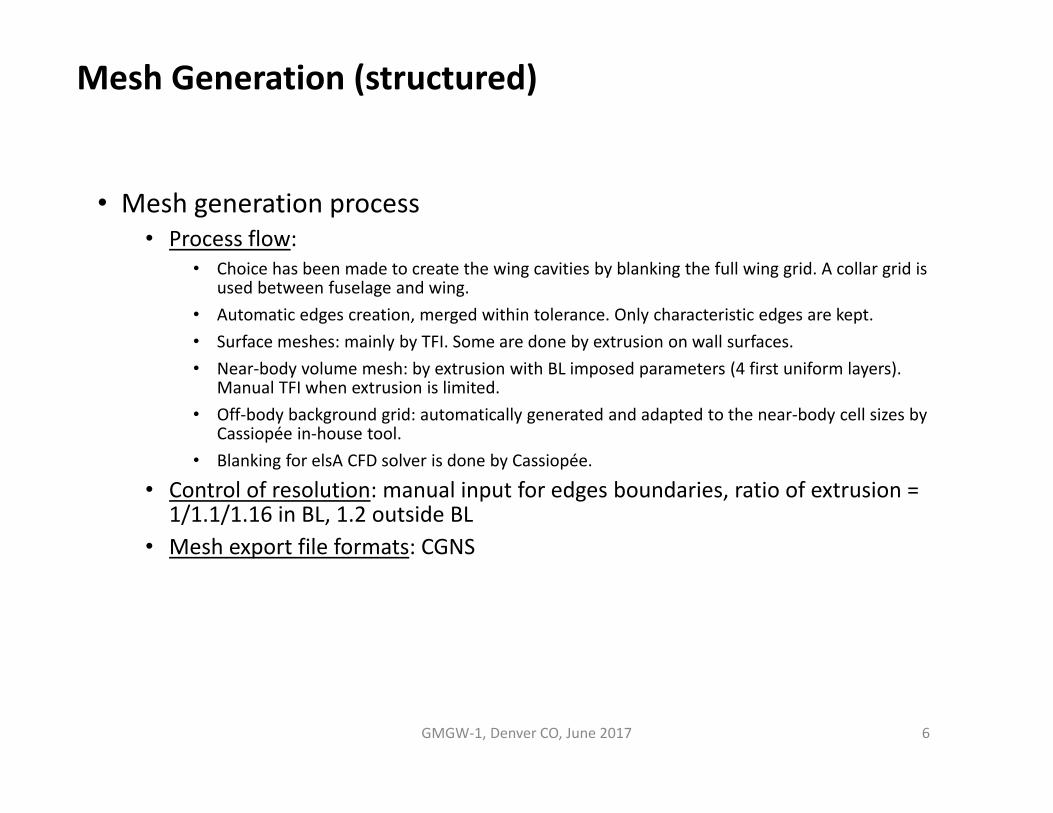
Mesh Generation (structured)
GMGW‐1, Denver CO, June 2017 6
• Mesh generation process• Process flow:
• Choice has been made to create the wing cavities by blanking the full wing grid. A collar grid is used between fuselage and wing.
• Automatic edges creation, merged within tolerance. Only characteristic edges are kept.• Surface meshes: mainly by TFI. Some are done by extrusion on wall surfaces.• Near‐body volume mesh: by extrusion with BL imposed parameters (4 first uniform layers).
Manual TFI when extrusion is limited.• Off‐body background grid: automatically generated and adapted to the near‐body cell sizes by
Cassiopée in‐house tool.• Blanking for elsA CFD solver is done by Cassiopée.
• Control of resolution: manual input for edges boundaries, ratio of extrusion = 1/1.1/1.16 in BL, 1.2 outside BL
• Mesh export file formats: CGNS
Mesh Generation (structured)
GMGW‐1, Denver CO, June 2017 7
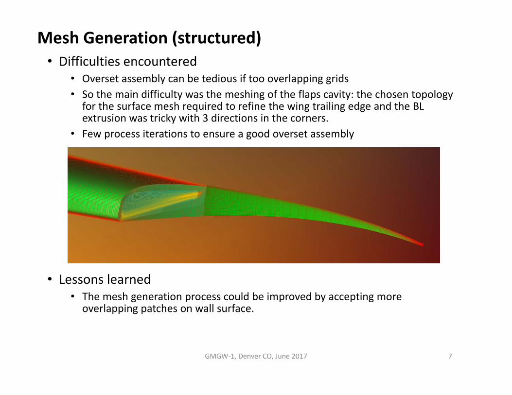
• Difficulties encountered• Overset assembly can be tedious if too overlapping grids• So the main difficulty was the meshing of the flaps cavity: the chosen topology
for the surface mesh required to refine the wing trailing edge and the BL extrusion was tricky with 3 directions in the corners.
• Few process iterations to ensure a good overset assembly
• Lessons learned• The mesh generation process could be improved by accepting more
overlapping patches on wall surface.

Mesh Statistics
GMGW‐1, Denver CO, June 2017 8
Geometry Model Grid Type Grid Level Nodes BFaces Volume Cells Jacobian Max. included angle<=0 Positive
skewMin max
HLCRM‐Full Gap Overset Structured Medium 52.0 M 370K 49.0M 0 2191
HLCRM‐Full Gap Unstructured HexaTetra Prism
Coarse 5.0 M 181K 7.9M 71.523 179.993
Medium 11.3 M 288K 18.6M 71.282 179.989
Max. included angle histogram for medium unstructured mesh

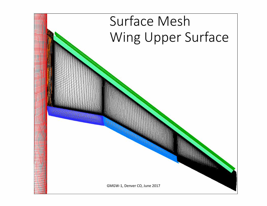
Surface MeshWing Upper Surface
9GMGW‐1, Denver CO, June 2017
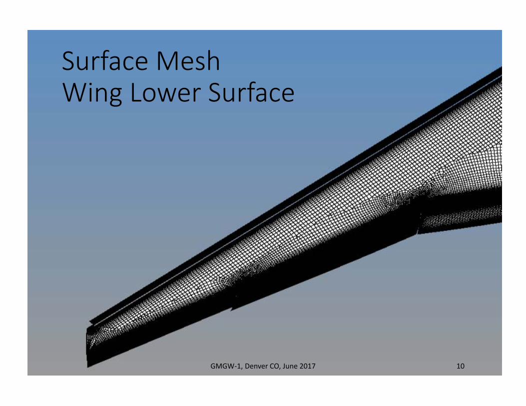
Surface MeshWing Lower Surface
GMGW‐1, Denver CO, June 2017 10
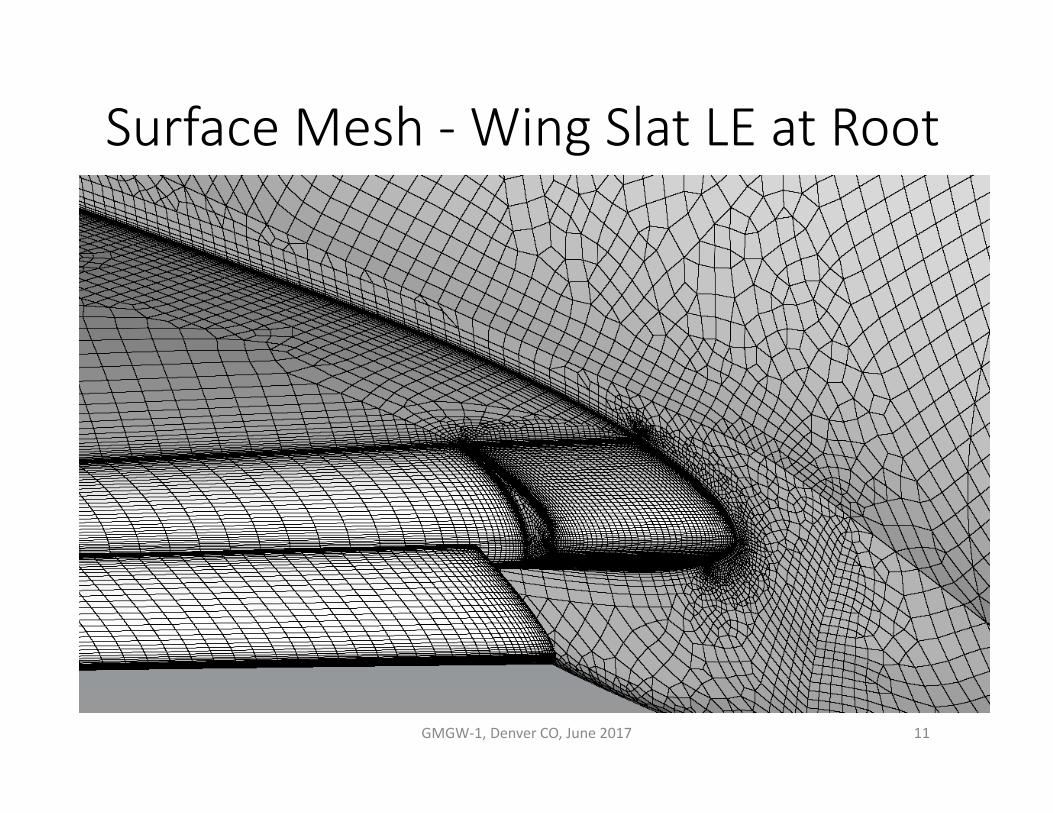
Surface Mesh ‐ Wing Slat LE at Root
GMGW‐1, Denver CO, June 2017 11
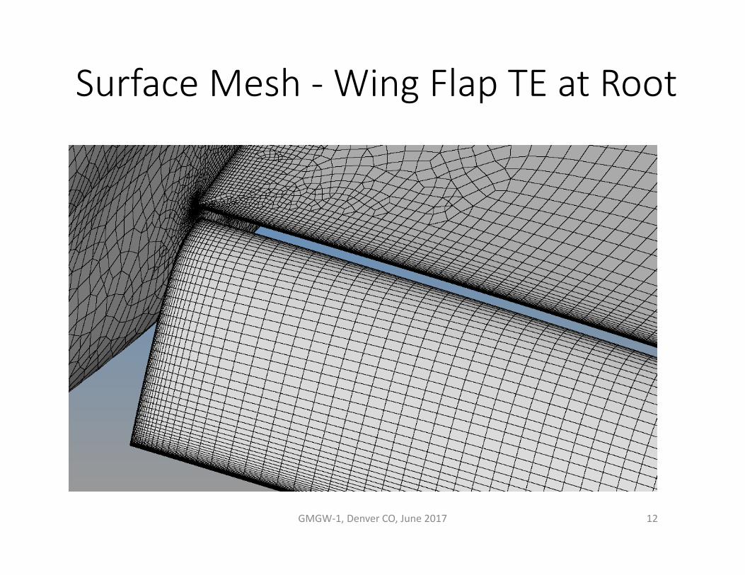
Surface Mesh ‐ Wing Flap TE at Root
GMGW‐1, Denver CO, June 2017 12

Surface Mesh ‐ Wing Tip LE
GMGW‐1, Denver CO, June 2017 13
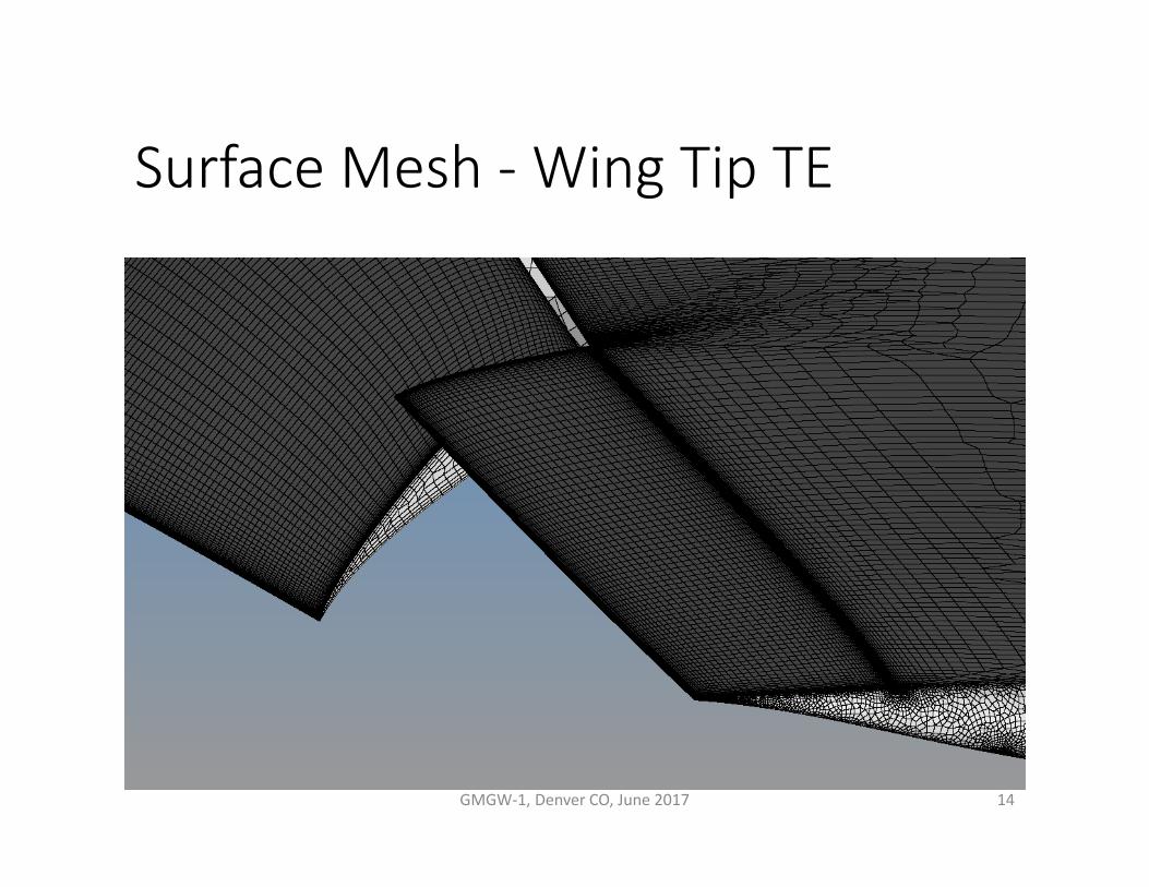
Surface Mesh ‐ Wing Tip TE
GMGW‐1, Denver CO, June 2017 14

Flap Gap Upper Surface
GMGW‐1, Denver CO, June 2017 15
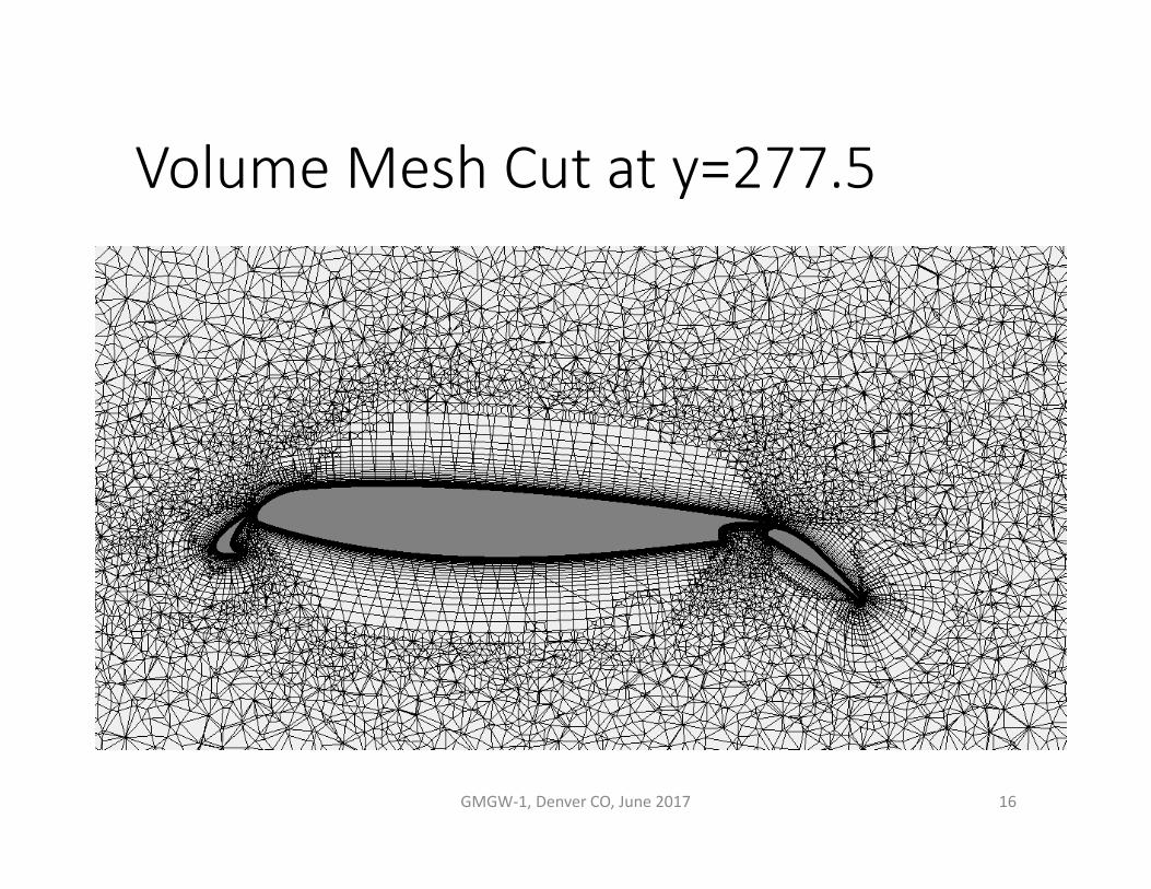
Volume Mesh Cut at y=277.5
GMGW‐1, Denver CO, June 2017 16
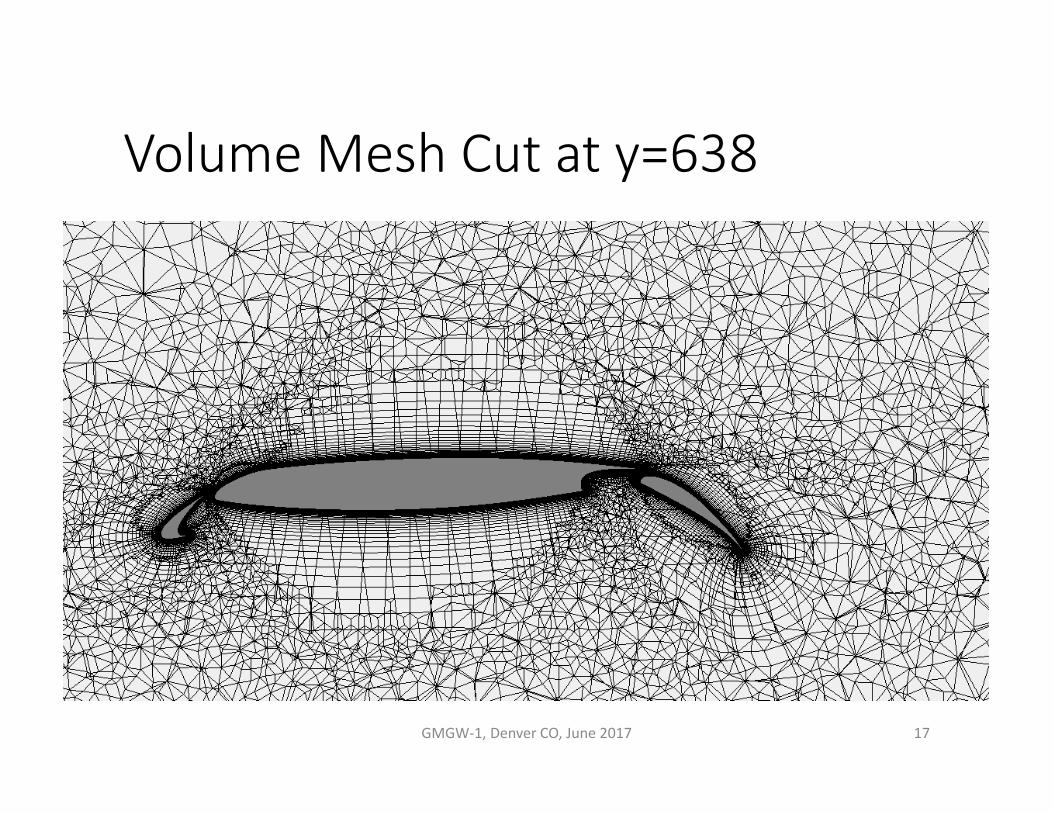
Volume Mesh Cut at y=638
GMGW‐1, Denver CO, June 2017 17

Volume Mesh Cut at y=1050
GMGW‐1, Denver CO, June 2017 18
Surface MeshWing Upper Surface
19GMGW‐1, Denver CO, June 2017

Surface MeshWing Lower Surface
GMGW‐1, Denver CO, June 2017 20
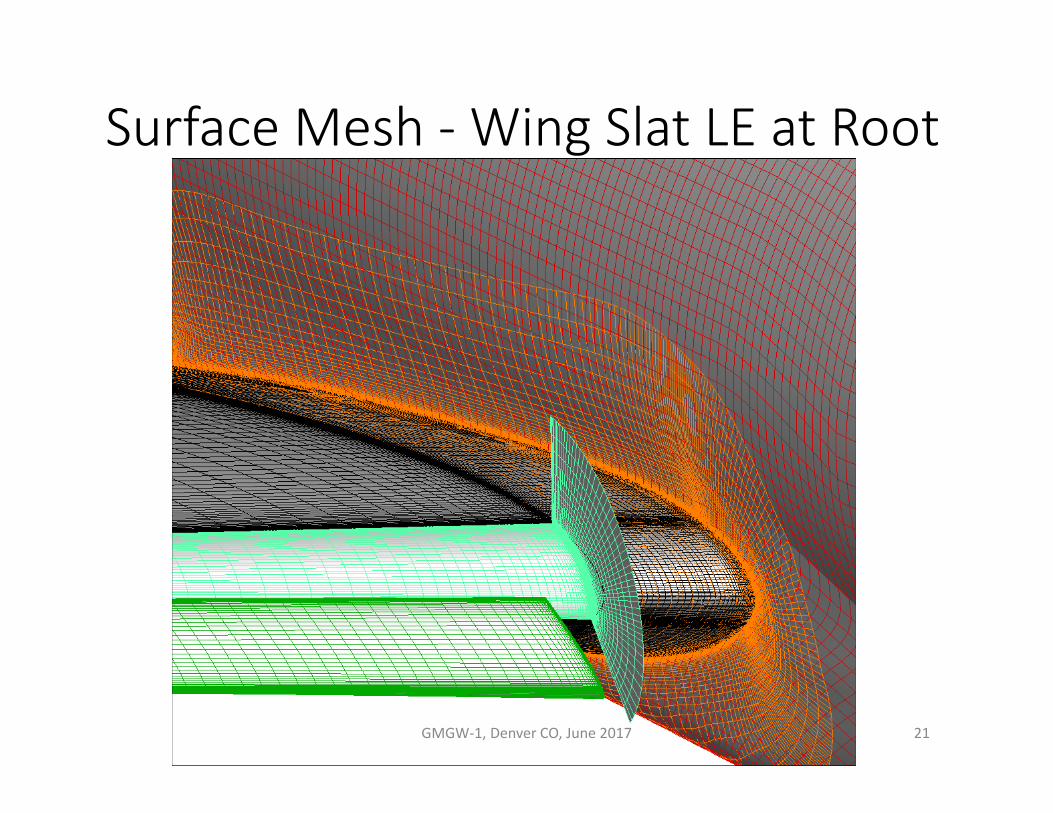
Surface Mesh ‐ Wing Slat LE at Root
GMGW‐1, Denver CO, June 2017 21

Surface Mesh ‐ Wing Flap TE at Root
GMGW‐1, Denver CO, June 2017 22
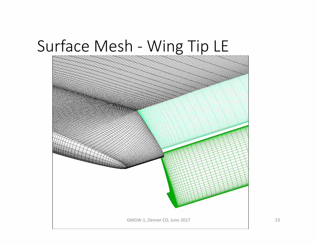
Surface Mesh ‐ Wing Tip LE
GMGW‐1, Denver CO, June 2017 23

Surface Mesh ‐ Wing Tip TE
GMGW‐1, Denver CO, June 2017 24

Flap Gap Upper Surface
GMGW‐1, Denver CO, June 2017 25

Volume Mesh Cut at y=277.5
GMGW‐1, Denver CO, June 2017 26
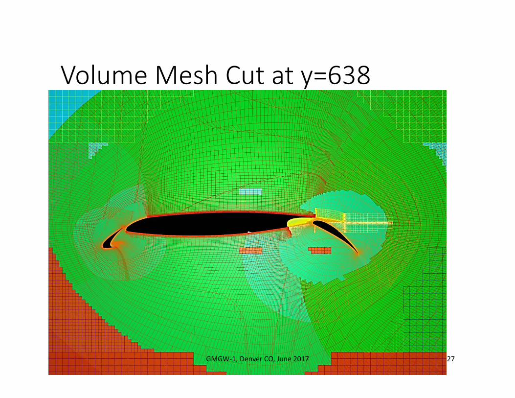
Volume Mesh Cut at y=638
GMGW‐1, Denver CO, June 2017 27

Volume Mesh Cut at y=1050
GMGW‐1, Denver CO, June 2017 28

Mesh Evaluation
GMGW‐1, Denver CO, June 2017 29
• Evaluation• Overset structured mesh: Jacobian >0 (positive skew ok), no orphan points
during overset assembly• Unstructured mesh: decrease the maximum included angle• Solution has been computed on the medium unstructured grid (not presented
at HLPW)• Low turb. visc. on slat intrados
• Adherence to meshing guidelines• Overset structured: not adherence for the 4x multigridable grids (not full
validated for overset grids with elsA) and for the cells alignment with wakes (lack of time)
• Unstructured: not adherence for the 4x multigridable grids (not possible with elsA), for the cells alignment with wakes (lack of time) and for the first constant BL layers (not possible with T‐Rex functionality)
Additional Topics
GMGW‐1, Denver CO, June 2017 30
• Future Technology • Improvement of unstructured mesh by local smoothing or cell shapes
deformation• ONERA works also on intersection of unstructured grids and on robustness of
extrusion for polyhedral meshes. It will be tested for HLCRM.

Summary
• What I learned from this exercise (first time I meshed a complex aircraft geometry)• What was the easiest? The geometry was clean (generally not the case)
• What was the hardest? For the structured grid, the extrusion in the flap cavity is tricky. For the unstructured grid, decreasing the max angle is difficult without crash. The cells alignment with component wakes can be tricky even with refinement source regions.
GMGW‐1, Denver CO, June 2017 31