Embed Size (px)
Citation preview
HAL Id: hal-01847099https://hal.archives-ouvertes.fr/hal-01847099
Submitted on 23 Jul 2018
HAL is a multi-disciplinary open accessarchive for the deposit and dissemination of sci-entific research documents, whether they are pub-lished or not. The documents may come fromteaching and research institutions in France orabroad, or from public or private research centers.
L’archive ouverte pluridisciplinaire HAL, estdestinée au dépôt et à la diffusion de documentsscientifiques de niveau recherche, publiés ou non,émanant des établissements d’enseignement et derecherche français ou étrangers, des laboratoirespublics ou privés.
Continuous vapor mode LGR manual Measuring waterstable isotopes (δD, δ 18 O, δ 17 O) using laser
spectroscopyDaniel Emanuelsson
To cite this version:Daniel Emanuelsson. Continuous vapor mode LGR manual Measuring water stable isotopes (δD, δ18 O, δ 17 O) using laser spectroscopy. [Research Report] GNS Science. 2017. �hal-01847099�
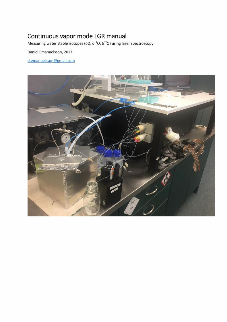
Continuous vapor mode LGR manual Measuring water stable isotopes (δD, δ18O, δ17O) using laser spectroscopy
Daniel Emanuelsson, 2017
1
Continuous mode
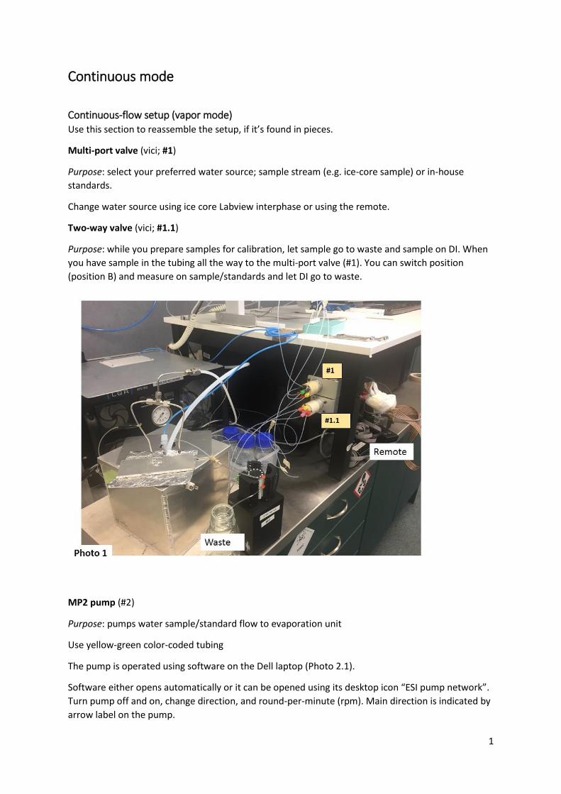
Continuous-flow setup (vapor mode) Use this section to reassemble the setup, if it’s found in pieces.
Multi-port valve (vici; #1)
Purpose: select your preferred water source; sample stream (e.g. ice-core sample) or in-house
standards.
Change water source using ice core Labview interphase or using the remote.
Two-way valve (vici; #1.1)
Purpose: while you prepare samples for calibration, let sample go to waste and sample on DI. When
you have sample in the tubing all the way to the multi-port valve (#1). You can switch position
(position B) and measure on sample/standards and let DI go to waste.
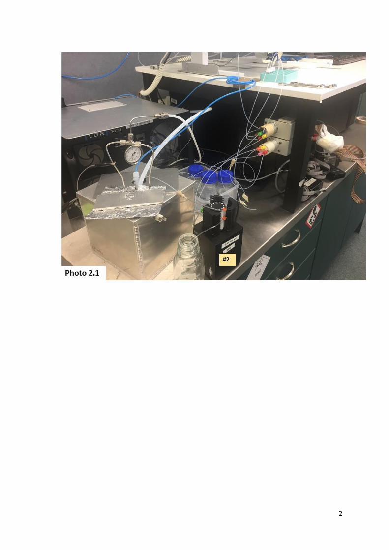
MP2 pump (#2)
Purpose: pumps water sample/standard flow to evaporation unit
Use yellow-green color-coded tubing
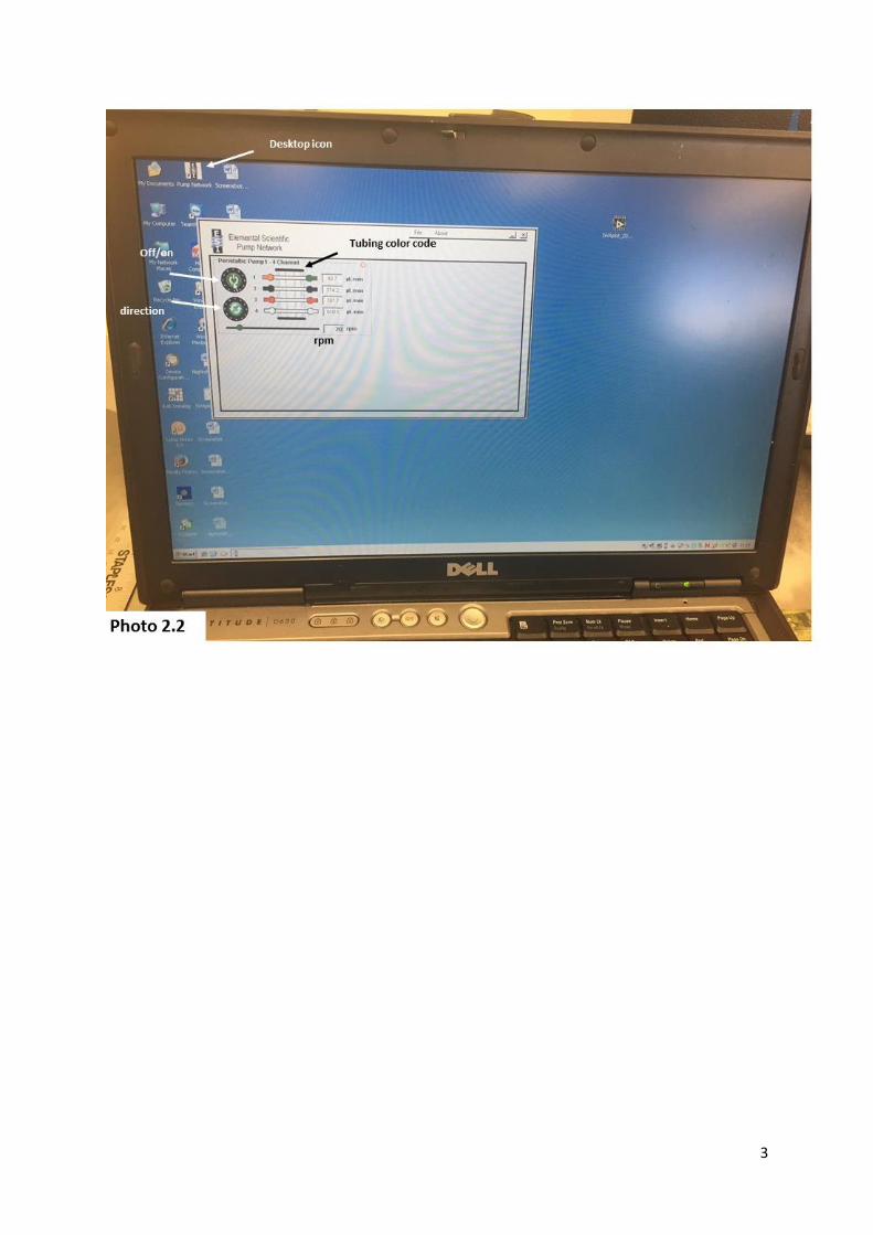
The pump is operated using software on the Dell laptop (Photo 2.1).
Software either opens automatically or it can be opened using its desktop icon “ESI pump network”.
Turn pump off and on, change direction, and round-per-minute (rpm). Main direction is indicated by
arrow label on the pump.
2
3
4
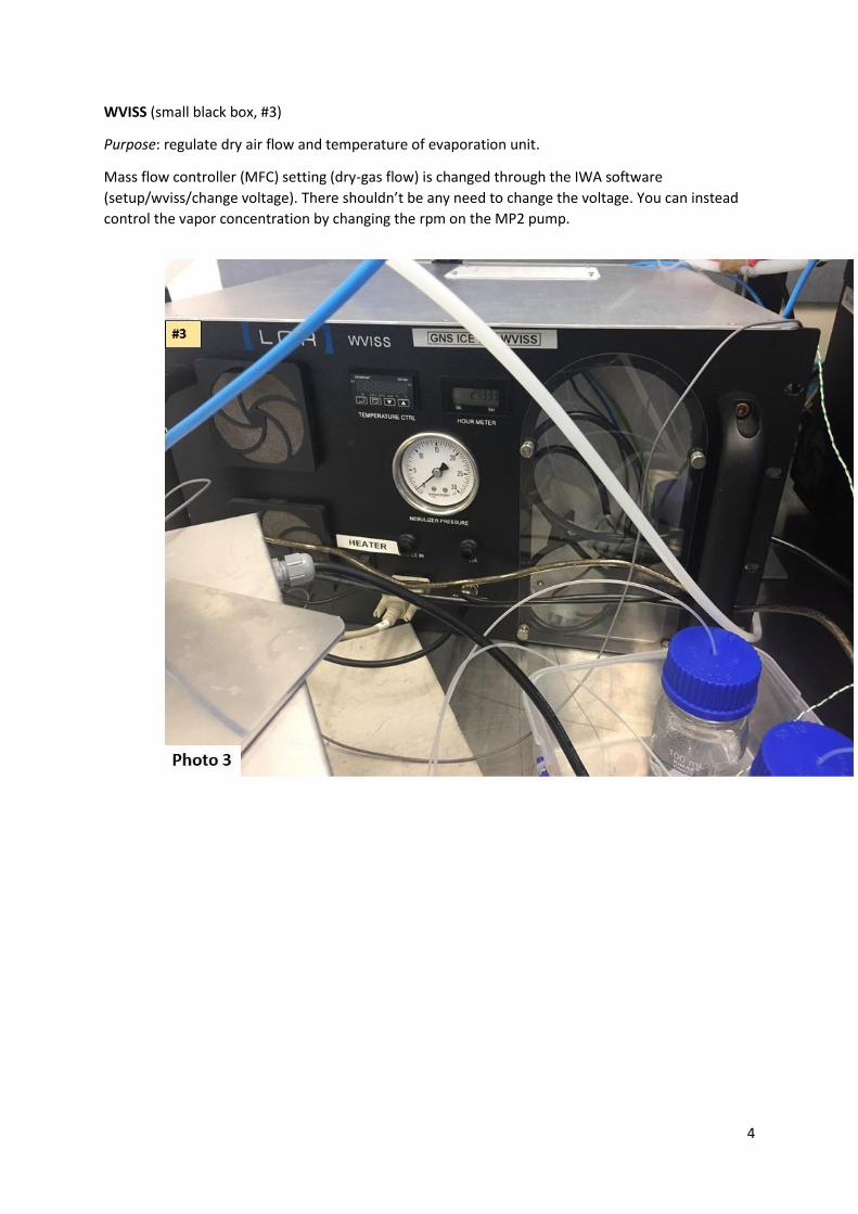
WVISS (small black box, #3)
Purpose: regulate dry air flow and temperature of evaporation unit.
Mass flow controller (MFC) setting (dry-gas flow) is changed through the IWA software
(setup/wviss/change voltage). There shouldn’t be any need to change the voltage. You can instead
control the vapor concentration by changing the rpm on the MP2 pump.
5
6
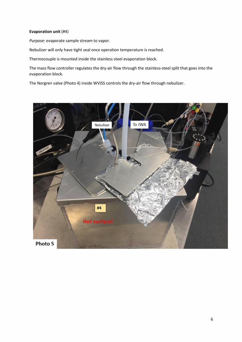
Evaporation unit (#4)
Purpose: evaporate sample stream to vapor.
Nebulizer will only have tight seal once operation temperature is reached.
Thermocouple is mounted inside the stainless steel evaporation block.
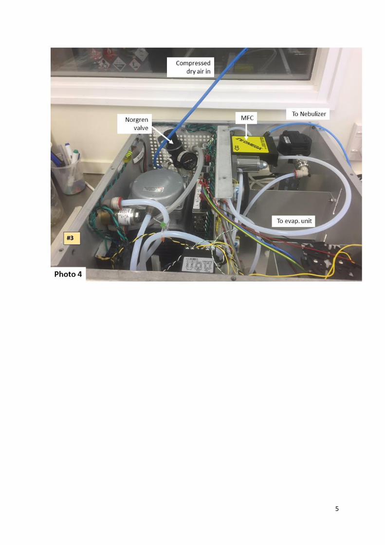
The mass flow controller regulates the dry-air flow through the stainless-steel split that goes into the
evaporation block.
The Norgren valve (Photo 4) inside WVISS controls the dry-air flow through nebulizer.
7
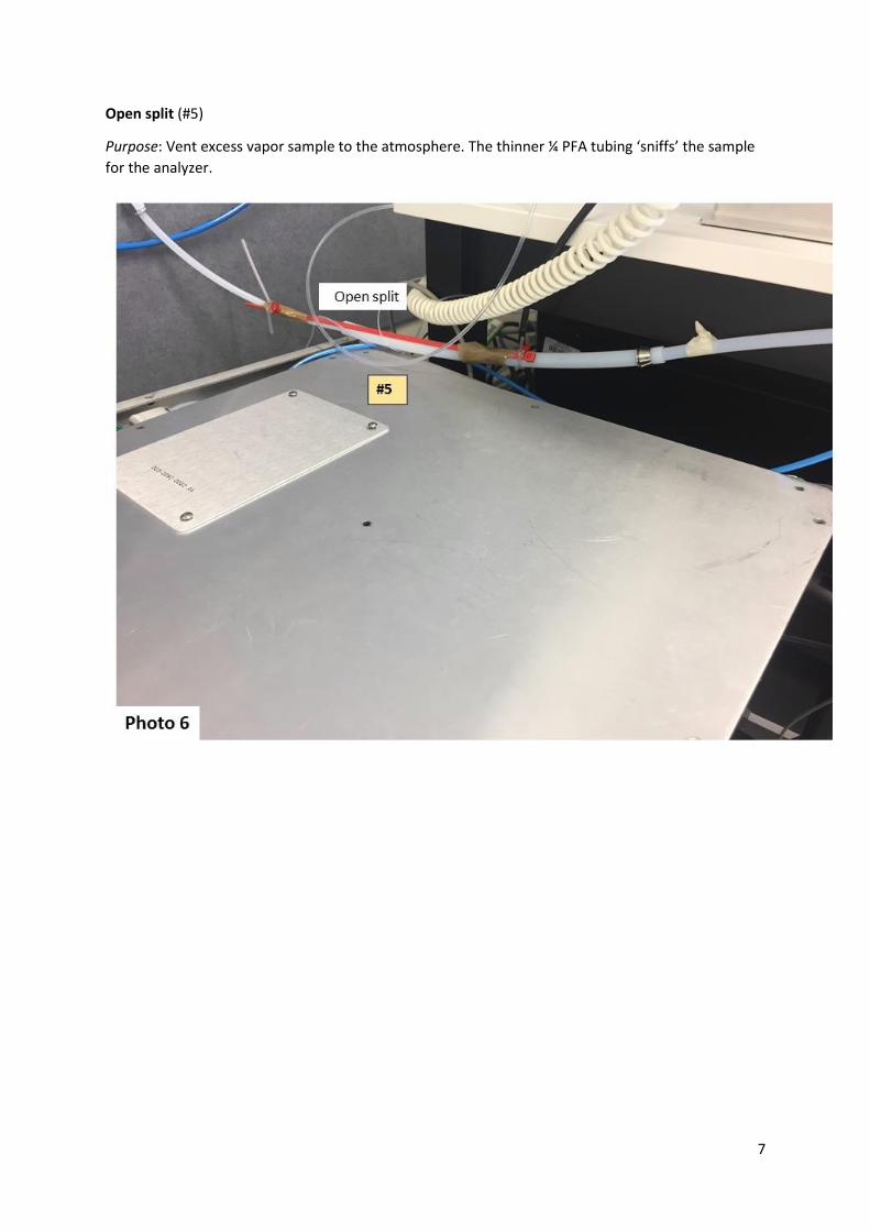
Open split (#5)
Purpose: Vent excess vapor sample to the atmosphere. The thinner ¼ PFA tubing ‘sniffs’ the sample
for the analyzer.
8
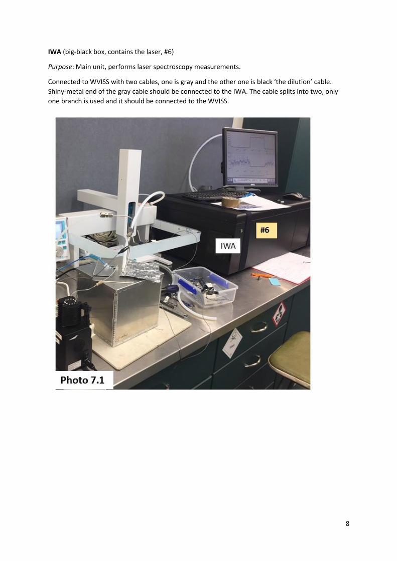
IWA (big-black box, contains the laser, #6)
Purpose: Main unit, performs laser spectroscopy measurements.
Connected to WVISS with two cables, one is gray and the other one is black ‘the dilution’ cable.
Shiny-metal end of the gray cable should be connected to the IWA. The cable splits into two, only
one branch is used and it should be connected to the WVISS.
9
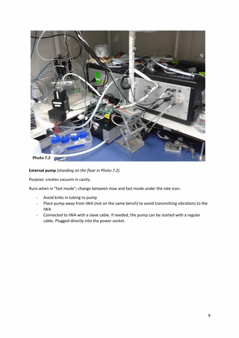
External pump (standing on the floor in Photo 7.2)
Purpose: creates vacuum in cavity.
Runs when in “fast mode”; change between slow and fast mode under the rate icon.
- Avoid kinks in tubing to pump
- Place pump away from IWA (not on the same bench) to avoid transmitting vibrations to the
IWA
- Connected to IWA with a slave cable. If needed, the pump can be started with a regular
cable. Plugged directly into the power socket.
10
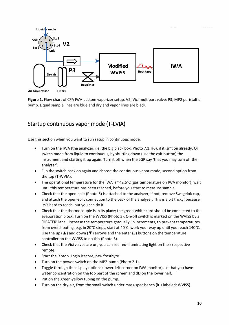
Figure 1. Flow chart of CFA IWA-custom vaporizer setup. V2, Vici multiport valve; P3, MP2 peristaltic
pump. Liquid sample lines are blue and dry and vapor lines are black.
Startup continuous vapor mode (T-LVIA)
Use this section when you want to run setup in continuous mode.
Turn on the IWA (the analyzer, i.e. the big black box, Photo 7.1, #6), if it isn’t on already. Or
switch mode from liquid to continuous, by shutting down (use the exit button) the
instrument and starting it up again. Turn it off when the LGR say ‘that you may turn off the
analyzer’.
Flip the switch back on again and choose the continuous vapor mode, second option from
the top (T-WVIA).
The operational temperature for the IWA is ~42.6°C (gas temperature on IWA monitor), wait
until this temperature has been reached, before you start to measure sample.
Check that the open-split (Photo 6) is attached to the analyzer, if not, remove Swagelok cap,
and attach the open-split connection to the back of the analyzer. This is a bit tricky, because
its’s hard to reach, but you can do it.
Check that the thermocouple is in its place; the green-white cord should be connected to the
evaporation block. Turn on the WVISS (Photo 3). On/off switch is marked on the WVISS by a
‘HEATER’ label. Increase the temperature gradually, in increments, to prevent temperatures
from overshooting, e.g. in 20°C steps, start at 40°C. work your way up until you reach 140°C.
Use the up (▲) and down (▼) arrows and the enter (↲) buttons on the temperature
controller on the WVISS to do this (Photo 3).
Check that the Vici valves are on, you can see red-illuminating light on their respective
remote.
Start the laptop. Login icecore, psw frostbyte
Turn on the power-switch on the MP2-pump (Photo 2.1).
Toggle through the display options (lower-left corner on IWA monitor), so that you have
water concentration on the top part of the screen and dD on the lower half.
Put on the green-yellow tubing on the pump.
Turn on the dry-air, from the small switch under mass-spec bench (it’s labeled: WVISS).
11
o The ppm on the top-part of the screen should go down from atmospheric
concentrations ~12,500 ppm to ~zero, which shows that we have no leaks. And the
pressure gauge on the WVISS (Photo 3) should show ~27 psi.
Start the pump, which is controlled from the laptop. Use the ESI ‘pump network’ icon on the
desktop (Photo 2.2).
Set rotation speed to ~20 rpm, check direction, and change direction if necessary. On the
top-part of the IWA screen the water concentration should now show about 20,000 ppm; it
should show a step change from zero ppm. Adjust the rpm pump rotation speed, if the
concertation deviates substantially from 20,000 ppm.
Flip the ‘warm-surface’ warning sign around.
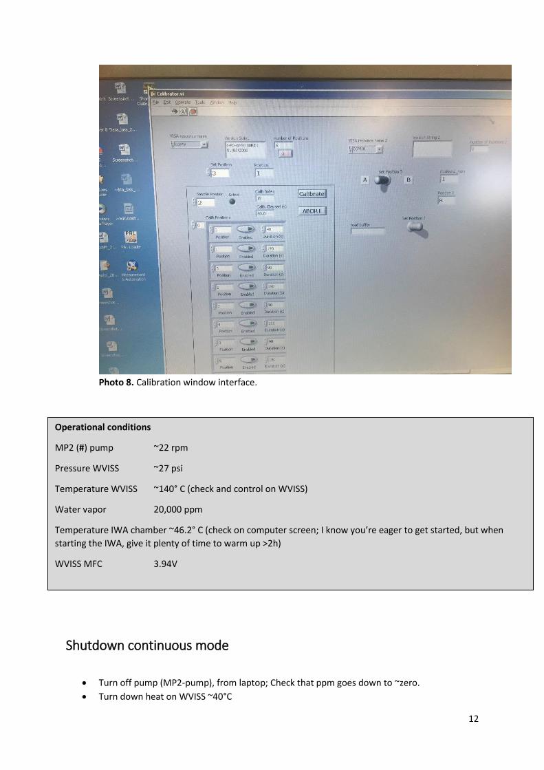
Open Labview-calibration interface, use shortcut on the laptop desktop “shortcut to
calibrator.exe”.
From the pull-down menu select COM port # 9 (Photo 8, top-left corner).
You should now get a text message in the window to the right (‘version string’, Photo 8), if
not restart the computer and try again.
To run liquid samples, from the same small vails that we use for the PAL, in continuous
mode. Set up a run cycles for position 1 to 6, as in Photo 8.
Change the default run times for each valve position to 90s.
Put the syringe needles into the vails (photo #)
Run the cycle and let the sample go to waste, position A on the two-way valve.
Once done, change the run time to 190s for all ports and switch to position B
Start calibration cycle
Once done switch back to position A
Prepare a new set of samples
12
Photo 8. Calibration window interface.
Shutdown continuous mode
Turn off pump (MP2-pump), from laptop; Check that ppm goes down to ~zero.
Turn down heat on WVISS ~40°C
Operational conditions
MP2 (#) pump ~22 rpm
Pressure WVISS ~27 psi
Temperature WVISS ~140° C (check and control on WVISS)
Water vapor 20,000 ppm
Temperature IWA chamber ~46.2° C (check on computer screen; I know you’re eager to get started, but when
starting the IWA, give it plenty of time to warm up >2h)
WVISS MFC 3.94V
13
Turn off dry-air; you should then start to see atmospheric conditions ~12,000 ppm.
Take off the green-orange tubing from the pump
Turn off WVISS. On/off switch is marked on the WVISS by a ‘HEATER’ label (Photo 3).
Consumables Tubing Teflon® High-purity PFA Tubing OD 1/16" tubing, 0.02" ID, 50 ft 2000 psig 0.02 in
0.0625 in, (order #: 1622L)
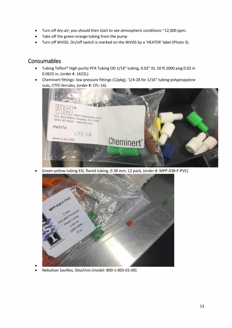
Cheminert fittings- low pressure fittings (12pkg), '1/4-28 for 1/16" tubing polypropylene
nuts, CTFE ferrules, (order #: CFL-1A)
Green-yellow tubing ESI, flared tubing, 0.38 mm, 12 pack, (order #: MPP-038-F-PVC)
Nebulizer Savillex, 50ul/min (model: 800-1-005-01-00)
14
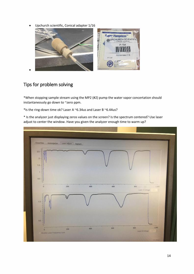
Upchurch scientific, Conical adapter 1/16
Tips for problem solving
*When stopping sample stream using the MP2 (#2) pump the water vapor concertation should
instantaneously go down to ~zero ppm.
*Is the ring-down time ok? Laser A ~6.34us and Laser B ~6.44us?
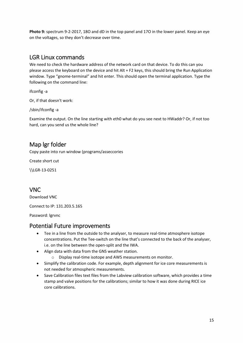
* Is the analyzer just displaying zeros values on the screen? Is the spectrum centered? Use laser
adjust to center the window. Have you given the analyzer enough time to warm up?
15
Photo 9: spectrum 9-2-2017, 18O and dD in the top panel and 17O in the lower panel. Keep an eye
on the voltages, so they don’t decrease over time.
LGR Linux commands We need to check the hardware address of the network card on that device. To do this can you
please access the keyboard on the device and hit Alt + F2 keys, this should bring the Run Application
window. Type “gnome-terminal” and hit enter. This should open the terminal application. Type the
following on the command line:
ifconfig -a
Or, if that doesn't work:
/sbin/ifconfig -a
Examine the output. On the line starting with eth0 what do you see next to HWaddr? Or, if not too
hard, can you send us the whole line?
Map lgr folder Copy paste into run window (programs/asseccories
Create short cut
\\LGR-13-0251
VNC Download VNC
Connect to IP: 131.203.5.165
Password: lgrvnc
Potential Future improvements Tee in a line from the outside to the analyser, to measure real-time atmosphere isotope
concentrations. Put the Tee-switch on the line that’s connected to the back of the analyser,
i.e. on the line between the open-split and the IWA.
Align data with data from the GNS weather station.
o Display real-time isotope and AWS measurements on monitor.
Simplify the calibration code. For example, depth alignment for ice core measurements is
not needed for atmospheric measurements.
Save Calibration files text files from the Labview calibration software, which provides a time
stamp and valve positions for the calibrations; similar to how it was done during RICE ice
core calibrations.
16
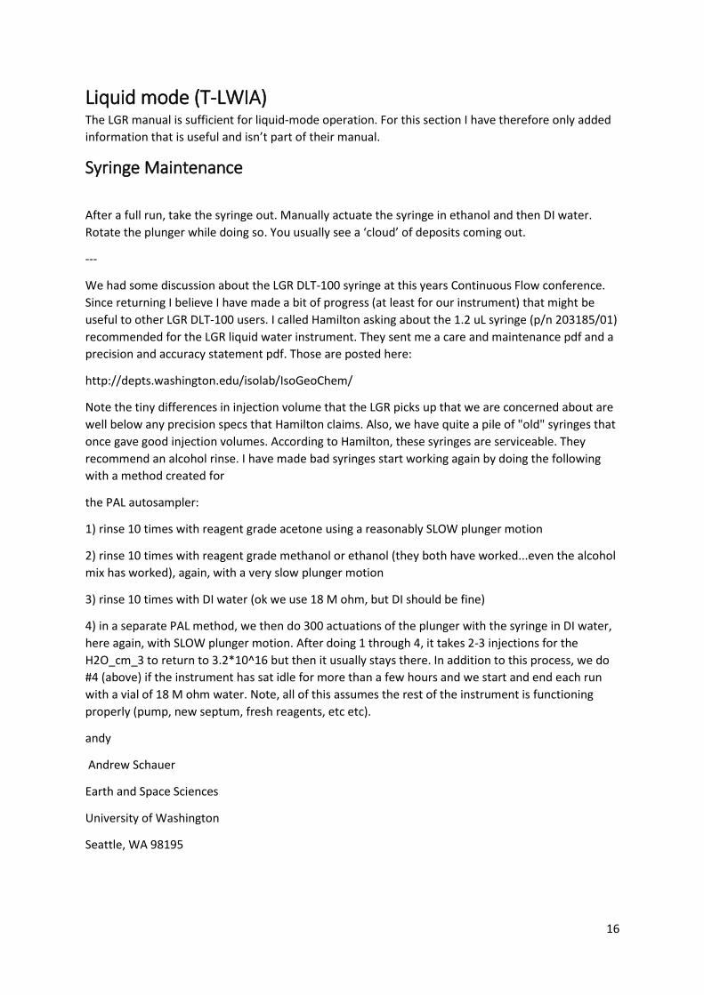
Liquid mode (T-LWIA) The LGR manual is sufficient for liquid-mode operation. For this section I have therefore only added
information that is useful and isn’t part of their manual.
Syringe Maintenance
After a full run, take the syringe out. Manually actuate the syringe in ethanol and then DI water.
Rotate the plunger while doing so. You usually see a ‘cloud’ of deposits coming out.
---
We had some discussion about the LGR DLT-100 syringe at this years Continuous Flow conference.
Since returning I believe I have made a bit of progress (at least for our instrument) that might be
useful to other LGR DLT-100 users. I called Hamilton asking about the 1.2 uL syringe (p/n 203185/01)
recommended for the LGR liquid water instrument. They sent me a care and maintenance pdf and a
precision and accuracy statement pdf. Those are posted here:
http://depts.washington.edu/isolab/IsoGeoChem/
Note the tiny differences in injection volume that the LGR picks up that we are concerned about are
well below any precision specs that Hamilton claims. Also, we have quite a pile of "old" syringes that
once gave good injection volumes. According to Hamilton, these syringes are serviceable. They
recommend an alcohol rinse. I have made bad syringes start working again by doing the following
with a method created for
the PAL autosampler:
1) rinse 10 times with reagent grade acetone using a reasonably SLOW plunger motion
2) rinse 10 times with reagent grade methanol or ethanol (they both have worked...even the alcohol
mix has worked), again, with a very slow plunger motion
3) rinse 10 times with DI water (ok we use 18 M ohm, but DI should be fine)
4) in a separate PAL method, we then do 300 actuations of the plunger with the syringe in DI water,
here again, with SLOW plunger motion. After doing 1 through 4, it takes 2-3 injections for the
H2O_cm_3 to return to 3.2*10^16 but then it usually stays there. In addition to this process, we do
#4 (above) if the instrument has sat idle for more than a few hours and we start and end each run
with a vial of 18 M ohm water. Note, all of this assumes the rest of the instrument is functioning
properly (pump, new septum, fresh reagents, etc etc).
andy
Andrew Schauer
Earth and Space Sciences
University of Washington
Seattle, WA 98195
17
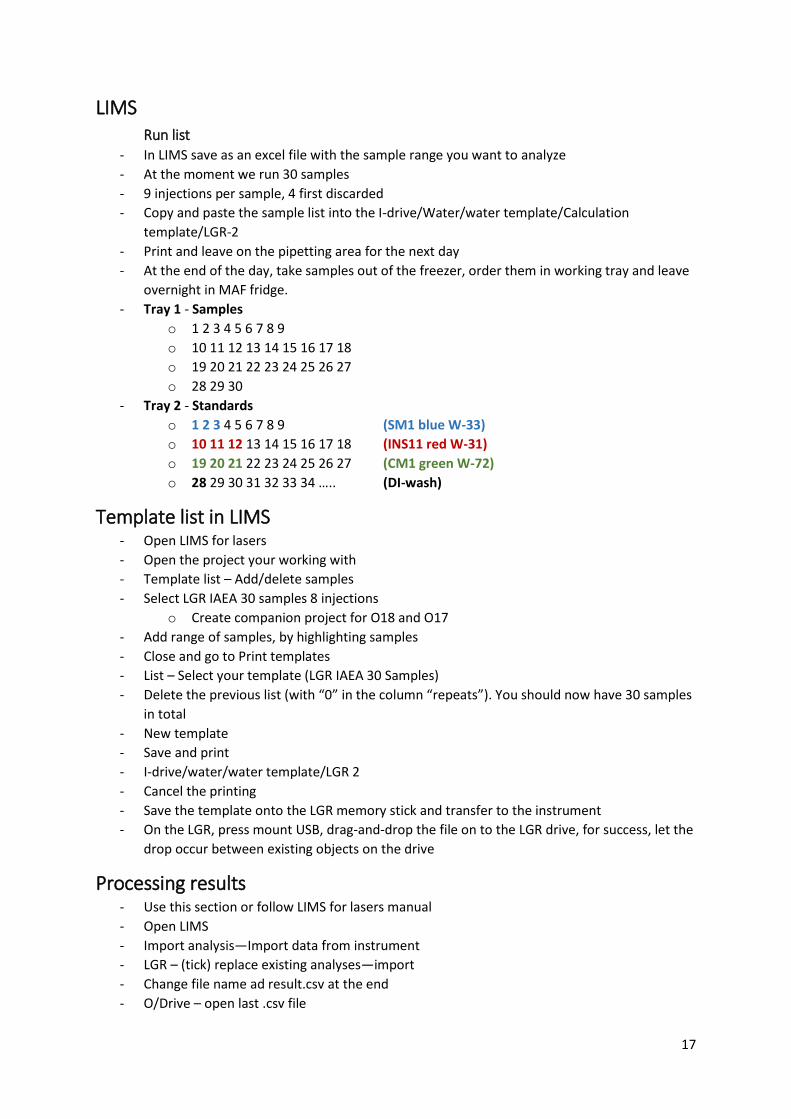
LIMS Run list
- In LIMS save as an excel file with the sample range you want to analyze
- At the moment we run 30 samples
- 9 injections per sample, 4 first discarded
- Copy and paste the sample list into the I-drive/Water/water template/Calculation
template/LGR-2
- Print and leave on the pipetting area for the next day
- At the end of the day, take samples out of the freezer, order them in working tray and leave
overnight in MAF fridge.
- Tray 1 - Samples
o 1 2 3 4 5 6 7 8 9
o 10 11 12 13 14 15 16 17 18
o 19 20 21 22 23 24 25 26 27
o 28 29 30
- Tray 2 - Standards
o 1 2 3 4 5 6 7 8 9 (SM1 blue W-33)
o 10 11 12 13 14 15 16 17 18 (INS11 red W-31)
o 19 20 21 22 23 24 25 26 27 (CM1 green W-72)
o 28 29 30 31 32 33 34 ….. (DI-wash)
Template list in LIMS - Open LIMS for lasers
- Open the project your working with
- Template list – Add/delete samples
- Select LGR IAEA 30 samples 8 injections
o Create companion project for O18 and O17
- Add range of samples, by highlighting samples
- Close and go to Print templates
- List – Select your template (LGR IAEA 30 Samples)
- Delete the previous list (with “0” in the column “repeats”). You should now have 30 samples
in total
- New template
- Save and print
- I-drive/water/water template/LGR 2
- Cancel the printing
- Save the template onto the LGR memory stick and transfer to the instrument
- On the LGR, press mount USB, drag-and-drop the file on to the LGR drive, for success, let the
drop occur between existing objects on the drive
Processing results - Use this section or follow LIMS for lasers manual
- Open LIMS
- Import analysis—Import data from instrument
- LGR – (tick) replace existing analyses—import
- Change file name ad result.csv at the end
- O/Drive – open last .csv file
18
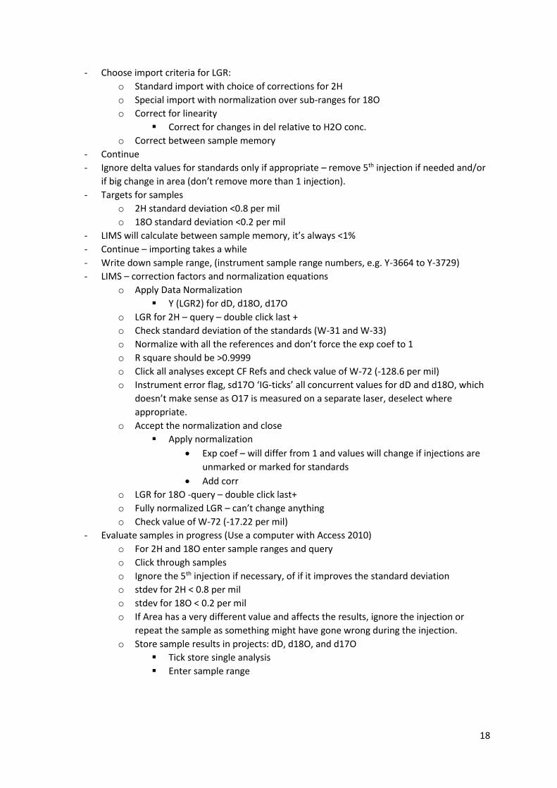
- Choose import criteria for LGR:
o Standard import with choice of corrections for 2H
o Special import with normalization over sub-ranges for 18O
o Correct for linearity
Correct for changes in del relative to H2O conc.
o Correct between sample memory
- Continue
- Ignore delta values for standards only if appropriate – remove 5th injection if needed and/or
if big change in area (don’t remove more than 1 injection).
- Targets for samples
o 2H standard deviation <0.8 per mil
o 18O standard deviation <0.2 per mil
- LIMS will calculate between sample memory, it’s always <1%
- Continue – importing takes a while
- Write down sample range, (instrument sample range numbers, e.g. Y-3664 to Y-3729)
- LIMS – correction factors and normalization equations
o Apply Data Normalization
Y (LGR2) for dD, d18O, d17O
o LGR for 2H – query – double click last +
o Check standard deviation of the standards (W-31 and W-33)
o Normalize with all the references and don’t force the exp coef to 1
o R square should be >0.9999
o Click all analyses except CF Refs and check value of W-72 (-128.6 per mil)
o Instrument error flag, sd17O ‘IG-ticks’ all concurrent values for dD and d18O, which
doesn’t make sense as O17 is measured on a separate laser, deselect where
appropriate.
o Accept the normalization and close
Apply normalization
Exp coef – will differ from 1 and values will change if injections are
unmarked or marked for standards
Add corr
o LGR for 18O -query – double click last+
o Fully normalized LGR – can’t change anything
o Check value of W-72 (-17.22 per mil)
- Evaluate samples in progress (Use a computer with Access 2010)
o For 2H and 18O enter sample ranges and query
o Click through samples
o Ignore the 5th injection if necessary, of if it improves the standard deviation
o stdev for 2H < 0.8 per mil
o stdev for 18O < 0.2 per mil
o If Area has a very different value and affects the results, ignore the injection or
repeat the sample as something might have gone wrong during the injection.
o Store sample results in projects: dD, d18O, and d17O
Tick store single analysis
Enter sample range
19
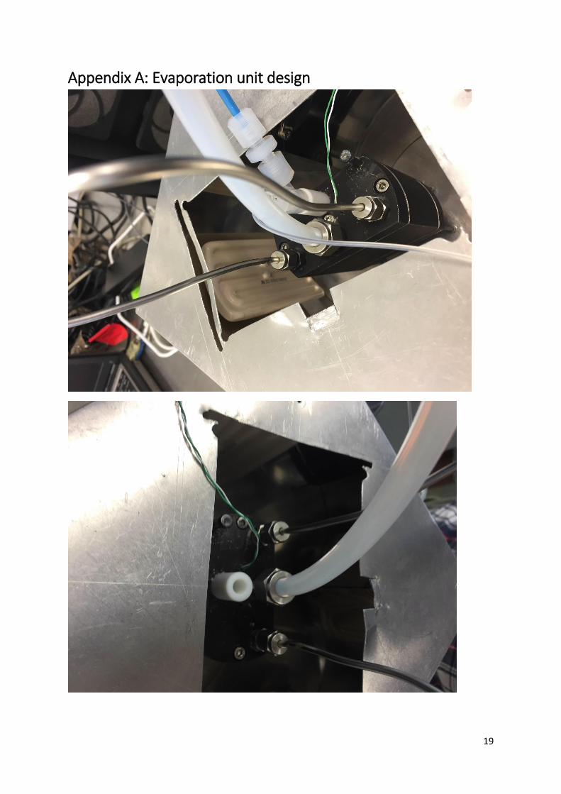
Appendix A: Evaporation unit design
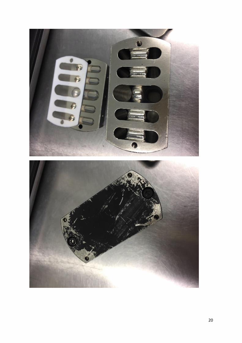
20
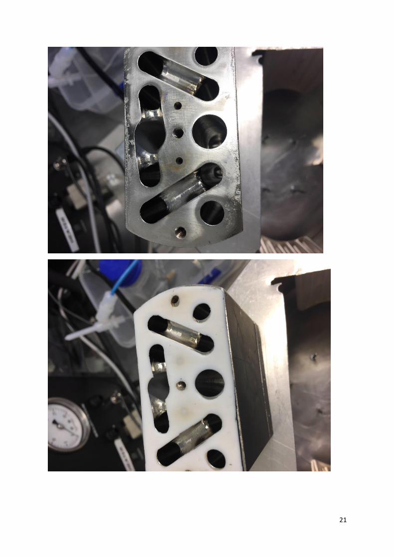
21
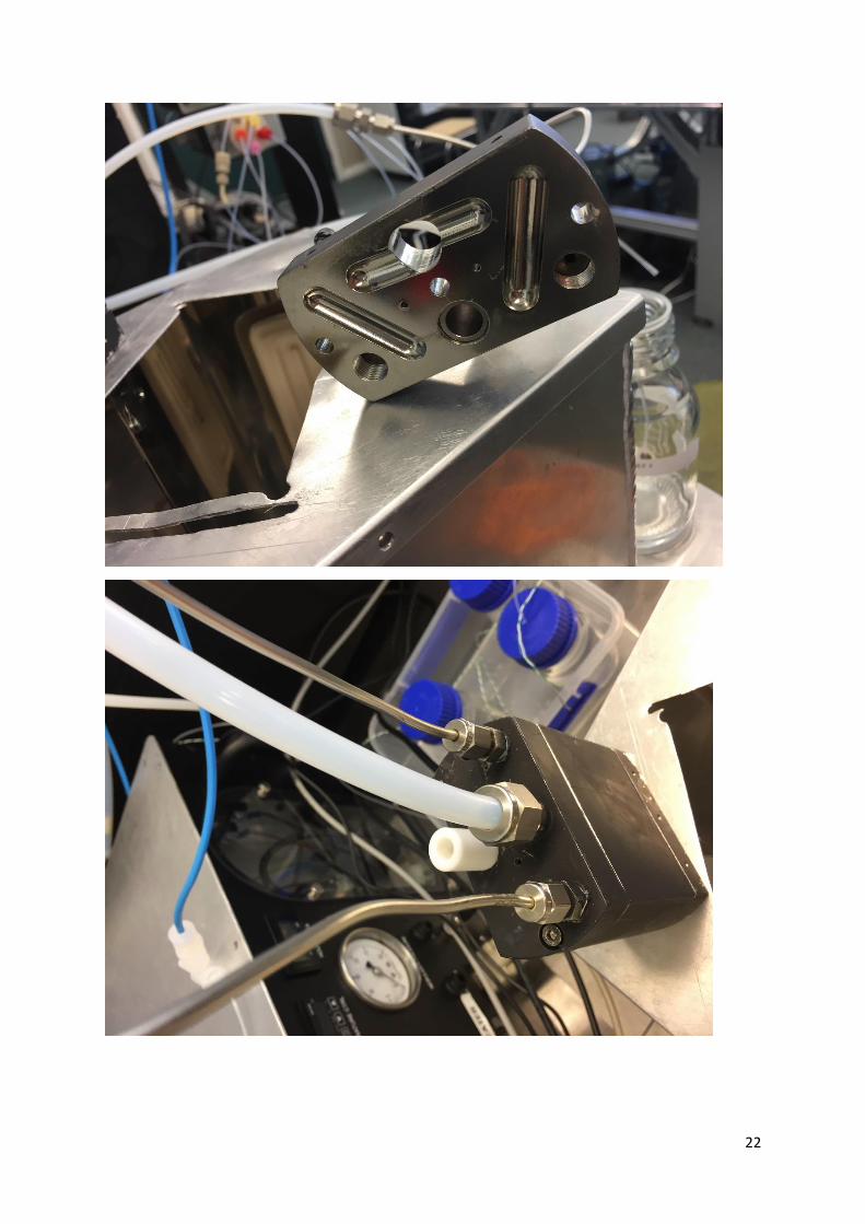
22

23