Embed Size (px)
Citation preview
Continuous Photo-Oxidation in a Vortex Reactor: EfficientOperations Using Air Drawn from the LaboratoryDarren S. Lee,† Zacharias Amara,† Charlotte A. Clark,† Zeyuan Xu,‡ Bruce Kakimpa,‡ Herve P. Morvan,‡
Stephen J. Pickering,‡ Martyn Poliakoff,*,† and Michael W. George*,†,§
†School of Chemistry, ‡Department of Mechanical, Materials and Manufacturing Engineering, University of Nottingham, UniversityPark, Nottingham, NG7 2RD, U.K.§Department of Chemical and Environmental Engineering, University of Nottingham Ningbo China, 199 Taikang East Road, Ningbo315100, China
*S Supporting Information
ABSTRACT: We report the construction and use of a vortex reactor which uses a rapidly rotating cylinder to generate Taylorvortices for continuous flow thermal and photochemical reactions. The reactor is designed to operate under conditions requiredfor vortex generation. The flow pattern of the vortices has been represented using computational fluid dynamics, and thepresence of the vortices can be easily visualized by observing streams of bubbles within the reactor. This approach presentscertain advantages for reactions with added gases. For reactions with oxygen, the reactor offers an alternative to traditional setupsas it efficiently draws in air from the lab without the need specifically to pressurize with oxygen. The rapid mixing generated bythe vortices enables rapid mass transfer between the gas and the liquid phases allowing for a high efficiency dissolution of gases.The reactor has been applied to several photochemical reactions involving singlet oxygen (1O2) including the photo-oxidations ofα-terpinene and furfuryl alcohol and the photodeborylation of phenyl boronic acid. The rotation speed of the cylinder proved tobe key for reaction efficiency, and in the operation we found that the uptake of air was highest at 4000 rpm. The reactor has alsobeen successfully applied to the synthesis of artemisinin, a potent antimalarial compound; and this three-step synthesis involvinga Schenk-ene reaction with 1O2, Hock cleavage with H+, and an oxidative cyclization cascade with triplet oxygen (3O2), fromdihydroartemisinic acid was carried out as a single process in the vortex reactor.
■ INTRODUCTION
Continuous flow chemistry is an increasingly popularalternative to traditional synthetic batch operations in bothacademic1,2 and industrial settings.3,4 As new developments aremade in synthetic methodology, fine chemical, and activepharmaceutical ingredient (API) synthesis, there is parallelinterest in translating these methodologies to continuousprocesses.5 Continuous flow chemistry can provide safer,more efficient, and automated operations, and hence researchinto this field is the focus of many academic groups. Reactionswhere scalability in batch is problematic have often benefittedfrom being applied to continuous reactors, and there have beensignificant achievements in developing different approacheswith many reactor designs being developed that address specificreaction difficulties.6−8
Photochemistry is an attractive synthetic tool, often deemeda green methodology, as it is frequently associated withefficient, mild and clean reaction conditions.9 Recently the fieldhas received much interest from both academic and industrialgroups and has been reviewed comprehensively.10−17 Con-tinuous flow photochemistry presents significant advantagesover more traditional batch reactions, as smaller path lengthreactors operating continuously can avoid issues such as lightpenetration, over irradiation and reactor fouling allowing foreasier scale-up. For example photochemical reactions, wherethe penetration of light is of key importance, have benefittedgreatly from a variety of innovative reactor designs.17 In thispaper we describe a new continuous flow reactor that we have
applied to photochemical reactions involving oxygen. Variouseffective designs have been reported in the literature for thesereactions; falling film,18,19 bubble column,20 spinning disc,21−23
slug flow,24,25 high pressure,26−28 FEP tubular,29 paralleltubular,30 rotating thin film,31 annular thin film,32 milling,33
and one recent design based on irradiating a nebulized liquid/gas mixture for singlet oxygen chemistry.34
Reactions with molecular oxygen (O2) are highly desirable asthey are highly atom economical and environmentally benign,and O2 is readily available and abundant in the atmosphere, butscale-up can present issues. Molecular oxygen is often used asan oxidant or as a reagent, where it can be incorporated intomolecules, in particular using photochemistry, where singletoxygen (1O2) is generated and reacted with electron-richfunctional groups.15,35−42 Such reactions are not often carriedout on a large scale because the use of pure oxygen posesseveral risks.43 A recent example34 that highlights the dilemmain scaling chemistry involving oxygen is a photoreactor designin which reaction solutions are nebulized into an atmosphere ofO2 or air creating fine droplets that are then irradiated. Thelarge surface area of the droplets result in highly efficientreactions because the interface between gas and liquid isincreased while the small diameter of the droplets means thatlight can more easily penetrate the solution. When flammablesolvents are used, however, the problem of potential ignition or
Received: April 24, 2017Published: July 3, 2017
Article
pubs.acs.org/OPRD
© 2017 American Chemical Society 1042 DOI: 10.1021/acs.oprd.7b00153Org. Process Res. Dev. 2017, 21, 1042−1050
This is an open access article published under a Creative Commons Attribution (CC-BY)License, which permits unrestricted use, distribution and reproduction in any medium,provided the author and source are cited.

explosion of the solvent is always present. Safe operation isoften realized by working below the limiting oxygenconcentration (LOC), a region in which combustion is notpossible.44,45 In practice this is often achieved by usingatmospheric or “synthetic” air (≤20% O2 in N2) instead ofpure O2. Unfortunately, using mixtures of gases often results ina loss of performance and slower reaction rates because lowerpartial pressures of oxygen result in lower concentrations of O2
in the reaction mixture. Nonflammable solvents, such assupercritical CO2 or H2O, can be used to reduce theflammability issues associated with pure O2; even thoughthese solvents exhibit high gas solubility, many organicsubstrates are virtually insoluble in them.46−48
Continuous flow reactors can be beneficial when using pureoxygen,49−51 as the precise delivery of reagents and gases can becontrolled, thereby giving greater control over stoichiometry.Furthermore, the reactors can be small, and the chances ofgenerating hazardous mixtures can be minimized. Continuousflow reactors can be pressurized and have high interfacial areasbetween the liquid and gas, allowing for greater dissolution ofgases into the solution. Pressurized systems introduce addi-tional hazards into the overall process. The ideal reactor wouldnot be pressurized and would generate a large interfacial areafor the reaction solution to interact with the oxygen, whichwould be supplied from the atmosphere. In essence, there is a
trade-off between the inherent safety of the reactor and thevolume of the gas phase and hence the area of the interface.Here we describe a different approach with a large liquid
volume and relatively small gas phase volume but with a highinterface area because the gas is present as very small bubbles.Our design is based on so-called “vortex reactors”52−59 whichhave been developed over the past 30 years. Here we bringtogether features from several previous reactors to make asurprisingly efficient reactor for photochemical reactionsinvolving oxygen.60
A vortex reactor consists of a cylindrical outer vessel fittedwith a smooth inner cylinder such that there only a relativelysmall gap between the inner and outer surfaces. The innercylinder is rotated at a relatively high speed, e.g., 4000 rpm(revolutions per minute) and generates so-called “Taylor” or“Taylor-Couette” vortices, relatively narrow toroidal vorticesthreaded around the central cylinder; the precise nature of thevortices and hence the degree of mixing depends quite stronglyon the dimensions of the reactor, the rotation speed of therotor, and the properties of the fluid. There are publishedexamples of vortex reactors operating in both vertical andhorizontal orientation. Our design brings together three keyfeatures from earlier designs: (i) A vortex reactor forphotochemistry, first demonstrated for the cleanup of pollutedwater using UV light and TiO2 particles suspended in thewater;58 (ii) the use of a vortex reactor for the thermal
Figure 1. (a) Showing the deconstructed reactor with the motor and its control box. A drive belt connects the motor and the rotating cylinder.During operation a protective housing (not shown) contains the motor, belt, and moving parts. (b) Showing the LEDs and mirror blocks mountedplace around the reactor. (c) Pipe diagram of the reactor setup showing the tubing connected to the reactor. Cooling is provided to the reactor by arecirculating chiller. The 3 LED blocks are connected in series and are cooled by a separate recirculating chiller. (d) A cross-section (not to scale) ofthe reactor showing the delivery and removal of reagents and the intake of air.
Organic Process Research & Development Article
DOI: 10.1021/acs.oprd.7b00153Org. Process Res. Dev. 2017, 21, 1042−1050
1043
oxidation of benzaldehyde with O2 or air (unlike our reactorthis one operated horizontally).52,56 (iii) A non-chemical reportof an open-topped vortex reactor which drew air into thereactor from the room as the rotor was spinning.57 Here weexplain how we have incorporated these three features, togetherwith modern high powered LED light sources, into a singlereactor for photochemical oxidations and validated our designwith dissolved oxygen studies. We then demonstrate its usewith four different reactions. Among the advantages of ourdesign is the fact that one does not require a separate supply ofoxygen or air; the reactor draws whatever air is needed from theatmosphere of the laboratory.
■ RESULTS AND DISCUSSIONReactor Design. The vortex reactor described in this study
was built in a vertical orientation such that LED blocks could bemore easily arranged around the outside of the reactor.61 Thereactor itself consists of a transparent Pyrex jacketed tube that issealed at the bottom and contains a polished stainless steelcylinder with a narrow bore running coaxially through thecenter. The gap between the cylinder and the jacket is ca. 1mm. The rotation of the stainless steel cylinder is provided by aspark free brushless motor that is housed to the side of thereactor and is connected to the cylinder using a drive belt. Thetop of the cylinder is held in place by an aluminum block toensure that it remains truly vertical; the block also housesbearings to ensure that the rotor can be rotated freely at highspeeds (Figure 1).All moving parts, including the motor, drive belt, and the top
of the cylinder with its bearings are housed inside an aluminumcase so that they are contained during operation. The rotationspeed is adjusted by a control box connected to the motor; therotation speed can be set between 50−4000 rpm in both aclockwise and anticlockwise direction. To deliver the reagentsinto the reactor, the top of the reactor is fitted with a 1/16”stationary Swagelok fitting that attaches to 1/16” tubing thatconnects to a HPLC pump (JASCO Pu980). The reagents aredelivered by this pump into the top of the reactor and downthrough the central bore of the stainless steel cylinder (Figure1d). The jacketed Pyrex tube broadens out into a “cup” at thetop to allow the reagent solution to exit the vortex zone of thereactor and be fed into an 1/8” PTFE tube connected to aperistaltic pump (Masterflex L/S). The flow rate of theperistaltic pump can be adjusted to suit the reagent deliveryflow rate so that there is no build-up of solution in the top ofthe reactor. The presence of a free liquid surface at the top ofthe reactor allows air to be entrained in the low-pressure regiongenerated by the rotation of the inner cylinder.Around the reactor sits a circular mount that holds three
LED blocks and three polished aluminum mirror blocks(Figure 1a−b). Each LED block consists of 5 × 1400 lmchips (Citizen Electronics part code: CL-L233-C13N1-C) andare positioned ca. 0.5 cm away from the jacketed reactor. Thejacketed reactor and the LEDs are connected to recirculatingchillers to ensure that the reactor temperature is constant byremoving heat from operating the LEDs banks. The wholereactor is mounted on a base which is dampened to limit anyvibrations created to by the reactor when it is operating at highrotation speeds. Two pillars provide a guide to ensure thehousing containing the motor, drive belt, and the rotatingcylinder are positioned correctly and at the same height. Thisallows for the whole set up to be easily removed, cleaned, andreplaced. Further details of the reactor are provided in the SI.
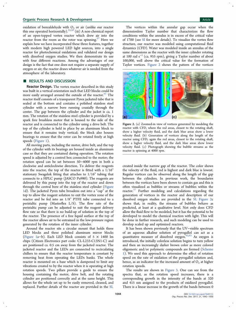
The vortices within the annular gap occur when thedimensionless Taylor number that characterizes the flowconditions within the annulus is in excess of the critical valueof 1700 (see SI for more details). To visualize the vortex flowstructure, our reactor was modeled using computational fluiddynamics (CFD). Water was modeled inside an annulus of thesame dimensions as the reactor with the inner cylinder rotatingat 100 rad s−1 (ca. 955 rpm), giving a Taylor number of about100,000, well above the critical value for the formation ofTaylor vortices. Figure 2 shows the pattern of the vortices
created inside the narrow gap of the reactor. The color showsthe velocity of the fluid, red is highest and dark blue is lowest.Regular vortices can be observed along the length of the gapbetween the cylinders. In previous work, the boundariesbetween the vortices have been shown to contain gas and this isoften visualized as bubbles or streams of bubbles within thereactor.57 Further modeling and calculations regarding thegeneration of vortices in the reactor and description of ourdissolved oxygen studies are provided in the SI. Figure 2cshows that, in reality, the streams of bubbles behave aspredicted, at least at a qualitative level. Not only does CFDallow the fluid flow to be modeled, but it has the potential to bedeveloped to model the chemical reaction with light. This willbe done in further research, and such modeling can be used todevelop scaled up and optimized reactors.It has been shown previously that the UV−visible spectrum
of an aqueous alkaline solution of pyrogallol can act as aquantitative measure of dissolved oxygen.62,63 As oxygen isintroduced, the initially colorless solution begins to turn yellowand then an increasingly darker brown color as more coloredoligomeric and/or polymeric compounds are formed (Scheme1). We used this approach to determine the effect of rotationspeed on the rate of oxidation of the pyrogallol solution and,hence, as an indicator for the increased amount of O2 at higherrotation speeds.The results are shown in Figure 3. One can see from the
spectra that, as the rotation speed increases, there is acorresponding growth in the intensity of the bands at 320and 415 nm assigned to the products of oxidized pyrogallol.There is a linear increase in the growth of the bands between 0
Figure 2. (a) Zoomed-in view of vortices generated by modeling thereactor with CFD, where the red areas, closest to the rotating shaft,show a higher velocity fluid, and the dark blue areas show a lowervelocity fluid. (b) Generation of vortices along the length of thereactor using CFD; again the red areas, closest to the rotating shaft,show a higher velocity fluid, and the dark blue areas show lowervelocity fluid. (c) Photograph showing the bubble streams as thereactor is spinning at 4000 rpm.
Organic Process Research & Development Article
DOI: 10.1021/acs.oprd.7b00153Org. Process Res. Dev. 2017, 21, 1042−1050
1044

and 3000 rpm with minimal further growth observed at 4000rpm, suggesting oxygen saturation of the solution.These results are in agreement with the general conclusions
of the modeling, which indicates that the flow regime in thereactor is well above the Taylor number for vortices to occurand that at higher speeds the mixing in the reactor will be morevigorous. As further confirmation, we employed the vortexreactor in several photochemical reactions involving oxygen; wepredicted that the yield should scale with the rotation speed.Initially, the reactor was benchmarked against the some well-known reactions before being applied to a more challengingreaction involving both 1O2 and
3O2.The initial benchmark of the reactor was the photo-oxidation
of α-terpinene (1) (Scheme 2). The yield of ascaridole (2) wasmeasured at different rotation speeds and flow rates.A solution of 1 in ethanol using Rose Bengal (2 mol %) was
flowed through the vortex reactor at a fixed flow rate of 0.5 mLmin−1 with the LEDs at full brightness. Beginning with thecylinder stationary, the spinning speed was increased withsamples taken at increments of 500 rpm. Two full reactor
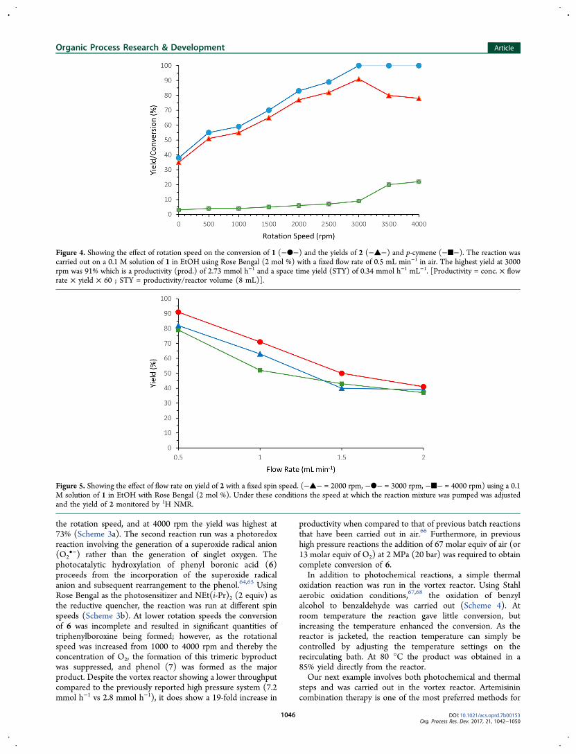
volumes were passed before the samples were taken to ensurethat the reactor had reached a steady state. The conversion of 1and the yields of 2 and 3 are plotted against rotation speed inFigure 4. Without any rotation, the yield of 2 was 35%; thisimproved as the rotation speed was increased up to 3000 rpmwhere the yield was 91%. Further increasing the spinning speedto 3500 and 4000 rpm had a detrimental effect on the yield of 2due to the increased formation of p-cymene (3). It is apparentthat as the speed was increased the reaction became moreefficient. At the higher speeds the shear forces and mixing willbe at their greatest; in addition gas−liquid interactions will beat their highest. In other words, the amount of oxygen availablefor reaction should increase as the rotation speed increases, andit would appear that O2 is the limiting factor for the reaction atthe slower spin speeds. To test this, reactions at 1000 and 1500rpm were repeated with double the concentration of photo-sensitizer (4 mol %); the yields of 2 remained unchangedsuggesting that the amount of oxygen is indeed the limitingfactor at these speeds. In the case of 3500 and 4000 rpm, wherethe yield of 2 drops as more p-cymene (3) is formed as abyproduct, is possibly explained by the higher concentration ofoxygen at these speeds. In this case it is likely that thephotosensitizer is the limiting factor and the yield of 2 is lessbecause of the competing oxidation reaction forming 3 with3O2. At 4000 rpm, when the concentration of Rose Bengal wasdoubled (to 4 mol %) the ratio of 2 to 3 improved from 3.5:1(at 2 mol %) to 9:1 (at 4 mol %) suggesting that the amount ofsinglet oxygen generated was important for maintaining a highselectivity. When 1 was flowed in the dark as a controlexperiment, the amount of 3 increased with increasing rotationspeed, where the p-cymene (3) yield was 4, 8, 11, and 15% at1000, 2000, 3000, and 4000 rpm, respectively.Next, the flow rate was changed while maintaining a fixed
rotation speed because it is possible that an increase in upwardflow could have an effect on the vortices. Flow rates of 0.5, 1.0,1.5, and 2.0 mL min−1 were investigated (at 2000, 3000, and4000 rpm). Increasing the flow rate, hence decreasing theresidence time in the reactor, led to a decrease in the yield of 1at all rotation speeds. At 1.5 mL min−1 and more so at 2 mLmin−1, the yields of 1 are very similar regardless of the rotationspeed, suggesting that at these flow rates the amount of O2 iscomparable despite the difference in speed and suggests thatthe higher upward flow rates have a greater or overriding effecton the vortices (Figure 5).To confirm that the faster rotation speeds, i.e., 4000 rpm,
were the most efficient for reactions to be carried out, two morephotochemical reactions involving singlet oxygen were run inthe vortex reactor (Scheme 3). In the absence of a competingreaction with 3O2 reaction, it was hypothesized that a rotationspeed of 4000 rpm would be most efficient.The photo-oxidation of furfural (4) with 1O2 is an unusual
reaction as the endoperoxide formed rearranges in the presenceof a nucleophilic solvent (i.e., water or alcohol) and results inthe breakage of a C−C bond to yield 5. When this reaction wasrun in the vortex reactor, as expected, the yield increased with
Scheme 1. Oxidation of Pyrogallol with Air in an AlkalineSolution
Figure 3. (a) UV−vis absorption spectra of aqueous basic pyrogallolsolution (3 mM) measured after exiting the vortex reactor at severalrotation speeds (0−4000 rpm); the flow rate was maintained at 1.0 mLmin−1. (b) Change in absorbance at 320 nm (■) and 415 nm (●)versus reactor rotation speed.
Scheme 2. Photo-Oxidation of α-terpinene 1 to Ascaridole 2and the Common Byproduct p-Cymene 3
Organic Process Research & Development Article
DOI: 10.1021/acs.oprd.7b00153Org. Process Res. Dev. 2017, 21, 1042−1050
1045
the rotation speed, and at 4000 rpm the yield was highest at73% (Scheme 3a). The second reaction run was a photoredoxreaction involving the generation of a superoxide radical anion(O2
•−) rather than the generation of singlet oxygen. Thephotocatalytic hydroxylation of phenyl boronic acid (6)proceeds from the incorporation of the superoxide radicalanion and subsequent rearrangement to the phenol.64,65 UsingRose Bengal as the photosensitizer and NEt(i-Pr)2 (2 equiv) asthe reductive quencher, the reaction was run at different spinspeeds (Scheme 3b). At lower rotation speeds the conversionof 6 was incomplete and resulted in significant quantities oftriphenylboroxine being formed; however, as the rotationalspeed was increased from 1000 to 4000 rpm and thereby theconcentration of O2, the formation of this trimeric byproductwas suppressed, and phenol (7) was formed as the majorproduct. Despite the vortex reactor showing a lower throughputcompared to the previously reported high pressure system (7.2mmol h−1 vs 2.8 mmol h−1), it does show a 19-fold increase in
productivity when compared to that of previous batch reactionsthat have been carried out in air.66 Furthermore, in previoushigh pressure reactions the addition of 67 molar equiv of air (or13 molar equiv of O2) at 2 MPa (20 bar) was required to obtaincomplete conversion of 6.In addition to photochemical reactions, a simple thermal
oxidation reaction was run in the vortex reactor. Using Stahlaerobic oxidation conditions,67,68 the oxidation of benzylalcohol to benzaldehyde was carried out (Scheme 4). Atroom temperature the reaction gave little conversion, butincreasing the temperature enhanced the conversion. As thereactor is jacketed, the reaction temperature can simply becontrolled by adjusting the temperature settings on therecirculating bath. At 80 °C the product was obtained in a85% yield directly from the reactor.Our next example involves both photochemical and thermal
steps and was carried out in the vortex reactor. Artemisinincombination therapy is one of the most preferred methods for
Figure 4. Showing the effect of rotation speed on the conversion of 1 (−●−) and the yields of 2 (−▲−) and p-cymene (−■−). The reaction wascarried out on a 0.1 M solution of 1 in EtOH using Rose Bengal (2 mol %) with a fixed flow rate of 0.5 mL min−1 in air. The highest yield at 3000rpm was 91% which is a productivity (prod.) of 2.73 mmol h−1 and a space time yield (STY) of 0.34 mmol h−1 mL−1. [Productivity = conc. × flowrate × yield × 60 ; STY = productivity/reactor volume (8 mL)].
Figure 5. Showing the effect of flow rate on yield of 2 with a fixed spin speed. (−▲− = 2000 rpm, −●− = 3000 rpm, −■− = 4000 rpm) using a 0.1M solution of 1 in EtOH with Rose Bengal (2 mol %). Under these conditions the speed at which the reaction mixture was pumped was adjustedand the yield of 2 monitored by 1H NMR.
Organic Process Research & Development Article
DOI: 10.1021/acs.oprd.7b00153Org. Process Res. Dev. 2017, 21, 1042−1050
1046

the treatment of malaria at present.69,70 Hence there isincreased motivation for more efficient and cost-effectiveroutes to artemisinin (8) (Scheme 5),71−73 especially now asthe precursor dihydroartemisinic acid (9) can be prepared onscale using bioengineered yeast.74 From 9 the synthesis of 8proceeds in three steps (Scheme 5): (i) photo-oxidation of 9with 1O2, (ii) Hock cleavage and rearrangement of the
hydroperoxide 10 facilitated by H+, (iii) oxidation with tripletO2 (
3O2) and subsequent cyclization to afford 8.While there are three steps from 9 to 8, the process is
generally carried out as a one-pot procedure as acid can beadded directly into the reaction mixture and the light sourcecan be turned off to stop the generation of 1O2.The synthesis of artemisinin (8) has previously been
reported by our group, with aqueous mixtures of THF orethanol, which gave high yields for 8, employed as greenalternatives to more traditional reaction solvents, such asdichloromethane.71 The previous batch protocol requiredirradiation for 1−5 h followed by up to 24 h stirring withbubbling O2. With the high gas liquid interface in the vortexreactor, it was envisaged that the two steps could be carried outsimultaneously and produce artemisinin (8) directly from thereactor. Initially, the steps were carried out independently toverify the photo-oxidation step in the vortex reactor. A 0.05 Msolution of 9 in THF:H2O (3:2) containing [Ru(bpy)3]Cl2 (0.1mol %) was flowed through the vortex reactor at 0.5 mL min−1
at 4000 rpm and 30 °C. Complete conversion of 9 to peroxides10 and 11 (9:1) was observed in the mixture obtained from thereactor outlet, so trifluoroacetic acid (TFA) was added to thecollected mixture of peroxides which were then stirred withbubbling O2 for 24 h to yield artemisinin in 60% as previouslyobserved. When TFA was present in the reaction mixture fromthe beginning, the results obtained after the reactor were morecomplicated, and the overall conversion of 9 was reduced to46% while the yield of 8 was obtained in just 5%. A variety ofconditions were screened to increase the conversion of 9 andthe yield of 8, as summarized in Table 1.Increasing the residence time by lowering the flow rate to
0.25 mL min−1 caused the yield of 8 increase accordingly to10% (Table 1, entry 2), lower flow rates were attempted but led
Scheme 3. Yields against Rotation Speed for the Photo-Oxidation for Furfural 4 and Phenyl Boronic Acid 6 in theVortex Reactora
aProd. = productivity = flow rate × 60 × concentration × yield.[Productivity = conc. × flow rate × yield × 60; STY = productivity/reactor volume (8 mL)].
Scheme 4. Stahl Aerobic Oxidation Run in the VortexReactor Using Aira
aProd. = 2.55 mmol h−1. STY = 0.32 mmol h−1 mL−1 [Productivity =conc. × flow rate × yield × 60 ; STY = productivity/reactor volume (8mL)].
Scheme 5. Formation of Artemisinin (8) from DHAA (9)
Table 1. Optimization of the Yield of 8 in the VortexReactora
entryphotosensitizer(mol %)b solvent
TFA(equiv)
temp.(°C)
conv.(%)c
yield 8(%)c
1 Ru (0.1) THF:H2O(3:2)
0.5 30 46 5
2d Ru (0.1) THF:H2O(3:2)
0.5 30 64 10
3 Ru (0.1) THF:H2O(3:2)
0.5 10 100 0e
4 Ru (0.1) THF:H2O(3:2)
0.5 50 28 <1
5f Ru (0.1) THF:H2O(3:2)
0.5 30 100 22
6 Ru (0.1) toluene 0.5 30 31 207 DCA (0.5) toluene 0.5 30 23 108 DCA (2.0) toluene 0.5 30 41 229 TPP (0.5) toluene 0.5 30 100 4510 TPP (0.5) toluene 0.5 25 100 50g
11 TPP (0.5) toluene 0.5 20 100 3912 TPP (0.5) toluene 0.1 25 100 4913 TPP (0.5) toluene 1 25 100 48
aReactions run with 9 (0.05 M in solvent), 4000 rpm, 0.5 mL min−1.bRu = [Ru(bpy)3]Cl2; DCA = 9,10-dicyanoanthracene; TPP =tetraphenylporphyrin. cDetermined by 1H NMR with biphenyl as aninternal standard. d0.25 mL min−1. e10 77%, 11 23%. fThe reactionmixture was recycled for 4 h. gProd. = 0.75 mmol h−1, STY = 0.094mmol h−1 mL−1 [Productivity = conc. × flow rate × yield × 60 ; STY= productivity/reactor volume (8 mL)].
Organic Process Research & Development Article
DOI: 10.1021/acs.oprd.7b00153Org. Process Res. Dev. 2017, 21, 1042−1050
1047

to irreproducible results. Lowering the temperature to 10 °C(Table 1, entry 3) slowed the Hock-cleavage step and yieldedpredominantly the peroxides 10 and 11; however, this time, ina 3.4:1 ratio, while no 8 was observed. Increasing thetemperature (Table 1, entry 4) proved detrimental to boththe yield and conversion. When the material was recycled for a4 h period, the yield of 8 peaked at 22%, but after 6 h the yieldbegan to fall suggesting that product degradation was occurringunder prolonged irradiation in the vortex reactor. Since thephoto-oxidation step could be completed in one pass throughthe reactor, it is likely that sufficient oxygen was present;therefore, the limiting step was in the conversion of 10 to 8.Considering the mechanism (Scheme 6) of the formation of 8from 10 highlighted that the equilibrium constant of the ketoand enol tautomers and hence the rate of formation of 8.Typically, keto tautomers are usually more stable than the enol.This equilibrium, however, can be influenced by severaldifferent factors favoring either form; in this case the type ofsolvent appears to be the predominant factor.75 In polar proticsolvent mixtures where hydrogen bond donation to the ketoneswill be prevalent, the keto form will be favored, asdemonstrated with aqueous THF or ethanol where theformation of 8 from 10 is slow, up to 24 h.71 In less polarsolvents, such as CH2Cl2, toluene, or perfluorinated solvents,the rate of formation of 8 from 10 is much faster; in this case,intramolecular hydrogen bonding between the enol andneighboring carbonyl will be predominant.72,76
When toluene was used as the reaction solvent, the yield of 8increased to 20%, but [Ru(bpy)3]Cl2 had poor solubility; hencea poor conversion was observed (Table 1, entry 6). Switchingthe photosensitizer to 9,10-dicyanoanthracene (DCA) affordeda remarkably clean 1H NMR spectra showing 8, 9, and littleelse, though both the yield and conversion were low (Table 1,entry 7). When the concentration of DCA was doubled, theconversion and yield increased 2-fold (Table 1, entry 8). Whentetraphenylporphyrin (TPP) was used in the reaction, it initially
reacted in the starting solution with TFA forming theprotonated porphyrin (TPP-H+), which is evident from themint green color of the reaction mixture. When TPP-H+ wasused, full conversion was observed, and a 45% yield ofartemisinin was obtained (Table 1, entry 9). When thetemperature was reduced to 25 °C, the yield increased furtherto 50%. However, further reducing the temperature to 20 °Cproved to be detrimental to the overall yield (Table 1, entries10−11). Finally, the concentration of TFA was changed to 0.1and to 1 equiv, however, both of these concentration yieldednearly identical results to using 0.5 equiv (Table 1, entries 12−13). The similarity in yield of 8 at the three concentrations ofTFA is potentially indicative of greater mixing and mass transferproperties of the vortex reactor and requires further studying asthe vortex reactor could be beneficial for other catalyst drivenreactions.
■ CONCLUSION
A continuous flow vortex reactor has been developed thatconsists of a fast spinning rotor that sits tightly inside a jacketedvessel; as it rotates toroidal vortices are generated in the narrowspace between the rotor and the jacket. This design bringstogether key features of other vortex reactors; having a lightsource for photochemistry and the introduction of air which isdrawn in from the laboratory atmosphere as the reactor spins.CFD modeling of the parameters of the reactor gavevisualization of the vortex stream inside the reactor; this isfurther supported by the visual appearance of streams of airbubbles as the reactor spins. Rotation speed appears to bedirectly linked to the amount of oxygen available to react, as at4000 rpm, as reaction yields improved as the rotation speed wasincreased. The synthesis of artemisinin was carried out in thereaction, where the choice of solvent was key to successfullytransferring the reaction from batch to continuous; in polarsolvents, the final oxidation step was slow, but in nonpolarsolvents it was fast enough that artemisinin could be obtained
Scheme 6. Hock Cleavage Step from Peroxide 10 Leading to the Keto and Enol Intermediates, The Equilibrium of Which LikelyDetermines the Rate at Which the Second Oxidation Occursa
aIn THF:H2O the equilibrium lies further to the keto form; hence the formation of 8 is slow. In nonpolar solvents, the enol form is likely to be morefavored which is demonstrated by an increase in the formation of 8.
Organic Process Research & Development Article
DOI: 10.1021/acs.oprd.7b00153Org. Process Res. Dev. 2017, 21, 1042−1050
1048

directly from the reactor outlet in 50% yield when using TPP asa photosensitizer. The concentration of acid made littledifference to the yield of artemisinin, suggesting that theintrinsic mixing properties of the reactor are well-tuned forcatalytic reactions. It is possible that very low catalyst loadingscould be applied to reaction without any substantial loss inefficiency. The reactors mixing properties could also bebeneficial for biphasic or triphasic mixtures, where having alarge interfacial area between two immiscible liquids or aliquid−gas mixture greatly improves efficiency. Simplemodifications to the reactor would enable alternative gases tobe applied; furthermore hazardous gases could be diluted withinert gases in the same way that oxygen is diluted in the air.There is potential for scale up of the vortex reactor as one couldsimply apply a rotor to an existing jacketed vessel much like thekind already used in process chemistry. We are currentlydeveloping a larger scale version of the vortex reactor andexploiting the current reactor in new chemistry. The CFDmodeling will also be developed to include the photochemicalreactions and effects of the second phase. This will give betterunderstanding of the process to allow scale up with greaterconfidence.
■ ASSOCIATED CONTENT*S Supporting InformationThe Supporting Information is available free of charge on theACS Publications website at DOI: 10.1021/acs.oprd.7b00153.
Further details of the reactor design, computational fluiddynamics (CFD), dissolved oxygen studies and exper-imental procedures, and representative 1H NMR spectra(PDF)
■ AUTHOR INFORMATIONCorresponding Authors*E-mail: [email protected].*E-mail: [email protected] S. Lee: 0000-0002-8288-1838NotesThe authors declare no competing financial interest.
■ ACKNOWLEDGMENTSWe thank EPSRC grants (EP/L021889/1), (EP/P013341/1),and the University of Nottingham EPSRC Impact Accelerationfund (EP/K503800/1) for supporting this work. The authorsalso thank the Bill and Melinda Gates Foundation (grant no.1070294). We also thank M. Dellar, C. Dixon, P. Fields, M.Guyler, D. Lichfield, M. McAdam, and R. Wilson for technicalsupport at the University of Nottingham. D.S.L. and C.A.C.would also like to thank Dr. Z. Abada, Dr. R. Horvath, E. N.DeLaney, and S. Miller for their useful discussions.
■ REFERENCES(1) Britton, J.; Raston, C. L. Chem. Soc. Rev. 2017, 46, 1250−1271.(2) Porta, R.; Benaglia, M.; Puglisi, A. Org. Process Res. Dev. 2016, 20,2−25.(3) Koenig, S. G.; Sneddon, H. F. Green Chem. 2017, 19, 1418−1419.(4) Gavriilidis, A.; Constantinou, A.; Hellgardt, K.; Hii, K. K. M.;Hutchings, G. J.; Brett, G. L.; Kuhn, S.; Marsden, S. P. React. Chem.Eng. 2016, 1, 595−612.(5) Plouffe, P.; Macchi, A.; Roberge, D. M. Org. Process Res. Dev.2014, 18, 1286−1294.
(6) Gutmann, B.; Kappe, C. O. Chim. Oggi. 2015, 33, 18−24.(7) Newman, S. G.; Jensen, K. F. Green Chem. 2013, 15, 1456−1472.(8) Wiles, C.; Watts, P. Green Chem. 2012, 14, 38−54.(9) Ciriminna, R.; Delisi, R.; Xu, Y. J.; Pagliaro, M. Org. Process Res.Dev. 2016, 20, 403−408.(10) Skubi, K. L.; Blum, T. R.; Yoon, T. P. Chem. Rev. 2016, 116,10035−10074.(11) Romero, N. A.; Nicewicz, D. A. Chem. Rev. 2016, 116, 10075−10166.(12) Remy, R.; Bochet, C. G. Chem. Rev. 2016, 116, 9816−9849.(13) Ravelli, D.; Protti, S.; Fagnoni, M. Chem. Rev. 2016, 116, 9850−9913.(14) Karkas, M. D.; Porco, J. A.; Stephenson, C. R. J. Chem. Rev.2016, 116, 9683−9747.(15) Ghogare, A. A.; Greer, A. Chem. Rev. 2016, 116, 9994−10034.(16) Chen, M.; Zhong, M. J.; Johnson, J. A. Chem. Rev. 2016, 116,10167−10211.(17) Cambie, D.; Bottecchia, C.; Straathof, N. J. W.; Hessel, V.; Noel,T. Chem. Rev. 2016, 116, 10276−10341.(18) Shvydkiv, O.; Limburg, C.; Nolan, K.; Oelgemoeller, M. J. FlowChem. 2012, 2, 52−55.(19) Jahnisch, K.; Dingerdissen, U. Chem. Eng. Technol. 2005, 28,426−427.(20) Yavorskyy, A.; Shvydkiv, O.; Limburg, C.; Nolan, K.; Delaure, Y.M. C.; Oelgemoeller, M. Green Chem. 2012, 14, 888−892.(21) Van Gerven, T.; Mul, G.; Moulijn, J.; Stankiewicz, A. Chem. Eng.Process. 2007, 46, 781−789.(22) Dionysiou, D. D.; Balasubramanian, G.; Suidan, M. T.;Khodadoust, A. P.; Baudin, I.; Laîne, J. M. Water Res. 2000, 34,2927−2940.(23) Barberis, K.; Howarth, C. R. Ozone: Sci. Eng. 1991, 13, 501−519.(24) Levesque, F.; Seeberger, P. H. Org. Lett. 2011, 13, 5008−5011.(25) Horie, T.; Sumino, M.; Tanaka, T.; Matsushita, Y.; Ichimura, T.;Yoshida, J.-i. Org. Process Res. Dev. 2010, 14, 405−410.(26) Bourne, R. A.; Han, X.; Poliakoff, M.; George, M. W. Angew.Chem., Int. Ed. 2009, 48, 5322−5325.(27) Han, X.; Bourne, R. A.; Poliakoff, M.; George, M. W. GreenChem. 2009, 11, 1787−1792.(28) Hall, J. F. B.; Bourne, R. A.; Han, X.; Earley, J. H.; Poliakoff, M.;George, M. W. Green Chem. 2013, 15, 177−180.(29) Hook, B. D. A.; Dohle, W.; Hirst, P. R.; Pickworth, M.; Berry,M. B.; Booker-Milburn, K. I. J. Org. Chem. 2005, 70, 7558−7564.(30) Elliott, L. D.; Berry, M.; Harji, B.; Klauber, D.; Leonard, J.;Booker-Milburn, K. I. Org. Process Res. Dev. 2016, 20, 1806−1811.(31) Clark, C. A.; Lee, D. S.; Pickering, S. J.; Poliakoff, M.; George,M. W. Org. Process Res. Dev. 2016, 20, 1792−1798.(32) DeLaney, E. N.; Lee, D. S.; Elliott, L. D.; Jin, J.; Booker-Milburn,K. I.; Poliakoff, M.; George, M. W. Green Chem. 2017, 19, 1431−1438.(33) Obst, M.; Konig, B. Beilstein J. Org. Chem. 2016, 12, 2358−2363.(34) Ioannou, G. I.; Montagnon, T.; Kalaitzakis, D.; Pergantis, S. A.;Vassilikogiannakis, G. ChemPhotoChem. 2017, 1, 173−177.(35) Ogilby, P. R. Chem. Soc. Rev. 2010, 39, 3181−3209.(36) Margaros, L.; Montagnon, T.; Tofi, M.; Pavlakos, E.;Vassilikogiannakis, G. Tetrahedron 2006, 62, 5308−5317.(37) Greer, A. Tetrahedron 2006, 62, 10613−10613.(38) Clennan, E. L.; Pace, A. Tetrahedron 2005, 61, 6665−6691.(39) DeRosa, M. C.; Crutchley, R. J. Coord. Chem. Rev. 2002, 233,351−371.(40) Frimer, A. A. Chem. Rev. 1979, 79, 359−387.(41) Ohloff, G. Pure Appl. Chem. 1975, 43, 481−502.(42) Kearns, D. R. Chem. Rev. 1971, 71, 395−427.(43) Hone, C. A.; Roberge, D. M.; Kappe, C. O. ChemSusChem 2017,10, 32−41.(44) Osterberg, P. M.; Niemeier, J. K.; Welch, C. J.; Hawkins, J. M.;Martinelli, J. R.; Johnson, T. E.; Root, T. W.; Stahl, S. S. Org. ProcessRes. Dev. 2015, 19, 1537−1543.(45) Brooks, M. R.; Crowl, D. A. J. Loss Prev. Process Ind. 2007, 20,144−150.
Organic Process Research & Development Article
DOI: 10.1021/acs.oprd.7b00153Org. Process Res. Dev. 2017, 21, 1042−1050
1049

(46) Bourne, R. A.; Han, X.; Poliakoff, M.; George, M. W. Angew.Chem., Int. Ed. 2009, 48, 5322−5325.(47) Bourne, R. A.; Han, X.; Chapman, A. O.; Arrowsmith, N. J.;Kawanami, H.; Poliakoff, M.; George, M. W. Chem. Commun. 2008,4457−4459.(48) Beckman, E. J. J. Supercrit. Fluids 2004, 28, 121−191.(49) Mallia, C. J.; Baxendale, I. R. Org. Process Res. Dev. 2016, 20,327−360.(50) Hone, C. A.; Roberge, D. M.; Kappe, C. O. ChemSusChem 2017,10, 32−41.(51) Pieber, B.; Kappe, C. O. In Organometallic Flow Chemistry; Noel,T., Ed.; Springer International Publishing: 2015; Vol. 57, p 97−136.(52) Hubacz, R.; Wronski, S. Exp. Therm. Fluid Sci. 2004, 28, 457−466.(53) Dutta, P. K.; Ray, A. K. Chem. Eng. Sci. 2004, 59, 5249−5259.(54) Dluska, E.; Wronski, S.; Ryszczuk, T. Exp. Therm. Fluid Sci.2004, 28, 467−472.(55) Dluska, E.; Wronski, S. Inz Chem. Procesowa 2004, 25, 813−818.(56) Dluska, E.; Wronski, S.; Hubacz, R. Chem. Eng. Sci. 2001, 56,1131−1136.(57) Atkhen, K.; Fontaine, J.; Wesfreid, J. E. J. Fluid Mech. 2000, 422,55−68.(58) Sczechowski, J. G.; Koval, C. A.; Noble, R. D. Chem. Eng. Sci.1995, 50, 3163−3173.(59) Kataoka, K.; Ohmura, N.; Kouzu, M.; Simamura, Y.; Okubo, M.Chem. Eng. Sci. 1995, 50, 1409−1416.(60) Raston and co-workers have also described a photoreactor thatinvolves rapid rotation, but it operates on quite a different principlebecause it generates a thin film with vortices on the inner surface of arapidly rotating transparent tube. Gandy, M. N.; Raston, C. L.; Stubbs,K. A. Chem. Commun. 2015, 51, 11041−11044.(61) In previous vortex photoreactors, the lamp(s) were placed in thecenter of the reactor rather than on the outside, thereby making thecooling of the lamp more complicated.(62) Williams, D. D.; Blachly, C. H.; Miller, R. R. Anal. Chem. 1952,24, 1819−1821.(63) Duncan, I. A.; Harriman, A.; Porter, G. Anal. Chem. 1979, 51,2206−2208.(64) Pitre, S. P.; McTiernan, C. D.; Ismaili, H.; Scaiano, J. C. J. Am.Chem. Soc. 2013, 135, 13286−13289.(65) Zou, Y. Q.; Chen, J. R.; Liu, X. P.; Lu, L. Q.; Davis, R. L.;Jorgensen, K. A.; Xiao, W. J. Angew. Chem., Int. Ed. 2012, 51, 784−788.(66) Penders, I. G. T. M.; Amara, Z.; Horvath, R.; Rossen, K.;Poliakoff, M.; George, M. W. RSC Adv. 2015, 5, 6501−6504.(67) Hoover, J. M.; Steves, J. E.; Stahl, S. S. Nat. Protoc. 2012, 7,1161−1166.(68) Hoover, J. M.; Stahl, S. S. J. Am. Chem. Soc. 2011, 133, 16901−16910.(69) Paddon, C. J.; Keasling, J. D. Nat. Rev. Microbiol. 2014, 12, 355−367.(70) Klayman, D. Science 1985, 228, 1049−1055.(71) Amara, Z.; Bellamy, J. F. B.; Horvath, R.; Miller, S. J.; Beeby, A.;Burgard, A.; Rossen, K.; Poliakoff, M.; George, M. W. Nat. Chem.2015, 7, 489−495.(72) Kopetzki, D.; Levesque, F.; Seeberger, P. H. Chem. - Eur. J.2013, 19, 5450−5456.(73) Levesque, F.; Seeberger, P. H. Angew. Chem., Int. Ed. 2012, 51,1706−1709.(74) Paddon, C. J.; Westfall, P. J.; Pitera, D. J.; Benjamin, K.; Fisher,K.; McPhee, D.; Leavell, M. D.; Tai, A.; Main, A.; Eng, D.; Polichuk, D.R.; Teoh, K. H.; Reed, D. W.; Treynor, T.; Lenihan, J.; Fleck, M.;Bajad, S.; Dang, G.; Dengrove, D.; Diola, D.; Dorin, G.; Ellens, K. W.;Fickes, S.; Galazzo, J.; Gaucher, S. P.; Geistlinger, T.; Henry, R.; Hepp,M.; Horning, T.; Iqbal, T.; Jiang, H.; Kizer, L.; Lieu, B.; Melis, D.;Moss, N.; Regentin, R.; Secrest, S.; Tsuruta, H.; Vazquez, R.;Westblade, L. F.; Xu, L.; Yu, M.; Zhang, Y.; Zhao, L.; Lievense, J.;Covello, P. S.; Keasling, J. D.; Reiling, K. K.; Renninger, N. S.;Newman, J. D. Nature 2013, 496, 528−532.
(75) Reichardt, C.; Welton, T. Solvents and Solvent Effects in OrganicChemistry; Wiley-VCH, 2010.(76) Turconi, J.; Griolet, F.; Guevel, R.; Oddon, G.; Villa, R.; Geatti,A.; Hvala, M.; Rossen, K.; Goller, R.; Burgard, A. Org. Process Res. Dev.2014, 18, 417−422.
Organic Process Research & Development Article
DOI: 10.1021/acs.oprd.7b00153Org. Process Res. Dev. 2017, 21, 1042−1050
1050