Embed Size (px)
Citation preview

Continuous discharge Penning source with emission linesbetween 50 A and 300 A
David S. Finley, Stuart Bowyer, Francesco Paresce, and Roger F. Malina
We have developed a modified Penning discharge lamp for use in the soft x-ray and extreme uv spectral re-gions. The source produces a number of intense lines in the 50-300-A range and can be operated for sub-stantial periods of time at high output levels before refurbishment is required. Refurbishment of thissource, when required, is very easily effected.
1. Introduction
In support of our astronomical' 2 and geophysical3research programs in the soft x-ray and extreme uvbands of the spectrum, we have developed an extensivesoft x-ray and extreme uv calibration facility. Weemploy two types of laboratory sources in connectionwith this facility: a Henke type source4 for soft x raysand a source developed by Paresce et al. 5 for productionof extreme uv radiation. These two sources cover muchof this spectral band, but there is a gap between 50 Aand 300 A, which is inadequately covered.
In this paper we describe a device we have developedwhich is specifically designed to cover this spectral re-gion. Essentially, this device is a continuous gas dis-charge source with the addition of an intense magneticfield through the discharge region. A device of thischaracter was first employed by Penning 6 as an ion-ization gauge. Deslattes et al.7 modified the Penningionization gauge to serve as a gas discharge source, buttheir device had essential limitations and was not widelyemployed. Subsequently several groups have builtversions of this type of source including Hartman 8 andWarden et al.9 These devices did not meet our re-quirements since none were reported as producing linesshortward of 160 A. Furthermore, these devices hadother limitations as a laboratory source. The intensemagnetic field required was produced by a large elec-tromagnet or permanent magnet mounted outside thesource, which results in a rather large and cumbersomedevice. Furthermore, this arrangement makes it dif-ficult to dismantle the source, and as it is a characteristicof this type of source that it has to be periodically dis-
The authors are with University of California, Space SciencesLaboratory, Berkeley, California 94720.
Received 13 May 1978.0003-6935/79/050649-06$00.50/0.© 1979 Optical Society of America.
mantled and refurbished, the dismantling processshould be as simple as possible.
11. Construction and Operation
A schematic diagram of the source is shown in Fig. 1.Electrons emitted from the cathode are constrained tofollow the magnetic field lines in very tight helices untilthey are scattered to the anode. An anomalously highenergy electron distribution is thereby developed in thedischarge region between the two anodes. These elec-trons excite a variety of lines, including both lines in-trinsic to the discharge gas and, more important, linesproduced by the excitation of highly ionized materialsputtered from the cathode faces. The axial magneticfield is produced by a pair of 38.1-mm X 12.7-mm sa-marium cobalt magnets, placed inside the cathodebodies. The upper and lower cathode plates are madeof mild steel, and the magnetic circuit is completed bysix 9.525-mm bolts, which clamp the unit together. Theresultant magnetic field in the discharge region is about2 kG. The cathode plates are at a negative potentialwith respect to the grounded anode and could pose ashock hazard. Thus as a precaution, each is covered bya Lexan cap. The cathode bodies are clamped down byDelrin rings, and cooling water is circulated throughthem. The cathode faces, held in place by retainingrings, can easily be replaced when necessary. The watercooled anode is made of brass and is insulated from thecathodes by means of Delrin spacers. The centralportion of the anode is removable, making the diameterof the discharge region easily alterable. We began witha 5-mm aperture and gradually increased it to 12.7 mm,obtaining greater photon fluxes with no loss of stability.However, a further increase to 16 mm made the sourcemuch more difficult to operate and brought about adecrease in the maximum radiation output. The sourceis of reasonable size (24 cm X 20 cm X 11 cm) and weighs11 kg. A picture of the source is shown in Fig. 2.
The source is mounted on the movable entrance siit
1 March 1979 / Vol. 18, No. 5 / APPLIED OPTICS 649

COOLING WATER
CATHODE PLATE-~~~~~ --kS-'\
MONOCHROMATOR PORT
I--_- Ii// -PtJMP PORT
ANODE ANODE INSERT
I 2 .0 2 4
I I I I I
6 8 IcFig. 1. Schematic of source. Gas inlet is normal to the plane of the diagram. The main body of the source has cylindrical symmetry about
a vertical centerline.
assembly of a 2.2-m MacPherson grazing incidencemonochromator, equipped with a 300-line/mm alumi-num coated concave grating, blazed at 2400 A. Thepressure of the gas in the discharge region is set by ad-justing the gas flow rate with a pair of fine needle valves.To facilitate ease of adjustment, the pressure betweenthe valves is lowered to a few hundred microns with asmall vacuum pump. A vacuum thermocouple gaugeis mounted on the slit assembly, and the source ispumped by a diffusion pump through a 1-m long flexiblemetal hose, with an ionization gauge mounted just up-stream from the diffusion pump. The source, in serieswith a 1.25 kQ ballast resistor, is powered by an 800-mAhigh-voltage regulated dc power supply. The radiationfrom the source, after being diffracted by the grating,passes through the exit slit into the calibration tank,where detectors and instruments are mounted.
In operation, the pressure in the monochromator andtank is kept below 10-5 Torr, but the pressure inside thedischarge region is rather uncertain. The thermocoupleonly indicates that the pressure is a micron or less, andthe ionization gauge reading, which is normally between5 X 10-5 Torr and 1 X 10⁻⁴ Torr, cannot readily beconverted to the absolute source pressure, since thatdepends on a variety of factors, including the gas flowrate, the effective pumping speed of the diffusion pump,the entrance slit size, the pumping action of the source
Fig. 2. Picture of the fully assembled source.
itself, etc. Relative readings, however, are sufficient foroptimizing the discharge. Typical operating parame-ters are 5 X 10- 5-Torr source pressure and 500-mAdischarge current at 1.5 kV.
The discharge characteristics of this source arepressure dependent. Under normal conditions, thedischarge is quite stable and is confined to the central
650 APPLIED OPTICS / Vol. 18, No. 5 / 1 March 1979
ANNE
SPACER
)cm
-
MGET
anode region. At the high pressure limit, a glow dis-charge takes place throughout the lamp. As the pres-sure is lowered, a critical pressure is reached belowwhich a discharge cannot be sustained.
As the source is being operated, material is contin-ually sputtered off the cathode faces. However, thegeometry of the source is such that after more than ahundred hours of operation, no detectable amount ofmetal has been observed to be deposited on the insu-lating spacers, nor on the grating. Most of the sput-tered metal is deposited on ridges at the edges of theanode hole. This causes no problem because when thecathode pieces are replaced, the anode insert can beremoved, and a spare clean one can be installed. Thecoated piece can then be scraped off and reused duringthe next cycle of operation. However, the metal whichis deposited on the anode can create difficulties. If thedischarge current is suddenly changed by a largeamount while the deposited layer is still thin, the re-sultant thermal variation can cause part of the metal topeel off, producing arcing, or even a direct short. Forthis reason, we always initially run the source for aboutan hour at -500 mA before changing the current orshutting down. Once the initial deposition is accom-plished, intermittent use with attendant thermal cyclingwill cause no problems.
The longevity of the cathode pieces depends on thematerial used and the operating characteristics of thedischarge. The sputtering rate with argon at 500 mAis -2 mm/h for magnesium cathode pieces and -0.8mm/h for aluminum cathode pieces. With 6.35-mmthick cathode pieces, this gives lifetimes of 3 h and 8 h,respectively. The source is designed to minimize thepossibility of sputtering through the water jacket by theaddition of a recess behind the center of the cathodepiece. When the cathode piece itself is sputteredthrough, the sharp edges around this hole become veryhot, causing the discharge current and voltage to varywildly. This condition is readily apparent to the op-erator, and the source can then be shut down. In oursystem we have an overload protection device on ourpower supply which automatically trips when thiscondition is reached thereby relieving the operator ofthis responsibility.
A peculiar feature of the operation of this lamp is thebreak-in procedure which is required. When the lampis first turned on, the pressure is higher than that en-countered during normal operation, and the radiationoutput consists of a high level of continuum with nolines evident. After about a half hour, it abruptlyswitches into the normal discharge mode, with thepressure dropping by a factor of 2 and the voltage risingby a factor of 2, for the same discharge current. Si-multaneously, the continuum flux decreases, and brightemission lines appear. Over the next quarter of anhour, the geometry of the discharge region continues tochange due to sputtering and redeposition of cathodematerial, thereby altering the discharge parameters.Thereafter, the source is quite stable with a drift on theorder of 1%/h for the voltage and current and a corre-sponding intensity change of no more than a few percentper hour.
Another characteristic to be noted is that when alu-minum cathodes are exposed to air, even after havingbeen broken in, a substantial oxide layer is developed.When the lamp' is turned on again, the voltage is typi-cally at half its normal value for a given current andpressure. The spectrum in this mode has many brightlines above 240 A due to 0 iiI, but the aluminum linesare excited only slightly. This condition persists for ahalf hour (at 500-mA discharge current) until the oxidelayer is sputtered away. The discharge then reverts toits normal mode. This suggests that when one is notinterested in the very short (X < 200-A) wavelengths,it is better to use aluminum cathodes with either oxygenor carbon dioxide as the discharge gas, since the sput-tering efficiencies for carbon and oxygen are small,10
and the moderate operating voltage required ensuresthat the sputtering rate will be quite low.
Ill. Results
A. Spectra
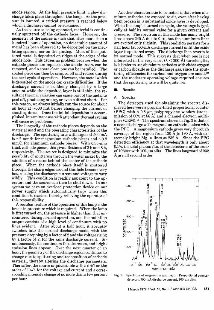
The detectors used for obtaining the spectra dis-played here were a propane-filled proportional counter(PPC) with a 0.8-,gm polypropylene window (trans-mission of 60% at 56 A) and a channel electron multi-plier (CEM).1 1 The spectrum shown in Fig. 3 is that ofa neon discharge with magnesium cathodes, taken withthe PPC. A magnesium cathode gives very thoroughcoverage of the region from 120 A to 190 A, with ex-tremely bright Mg III lines at 232 A. Since the PPCdetection efficiency at that wavelength is only about0.1%, the total photon flux at the detector is of the orderof 105/sec with 100-gim slits. The lines longward of 232A are all second order.
I I I II I I I I I I I I I I I
1000 -0
800-
600 0
Lu
2400-
0 120 40 160 180 200 220 240 260 280WAVELENGTH (A)
Fig. 3. Spectrum of magnesium and neon. Proportional counterdetector, 700-mA discharge current, 100-,um slits.
1 March 1979 / Vol. 18, No. 5 / APPLIED OPTICS 651

160 180 200 220 240WAVELENGTH(A)
Fig. 4. Spectrum of aluminum and neon. Channplier detector, 500-mA discharge current, 1.5 kV,
40-jum slits.
The spectrum shown in Fig. 4 is that charge with aluminum cathodes and is t,CEM detector. The Al IV pair at 161 Abe quite useful. At discharge currents ofintensities in excess of 107 photons/sEachieved, making calibration of a detecphotodiode quite feasible. Of spectroscopthe aluminum lines at 232 A and 234 A,listed in Kelly and Palumbo,' 2 nor are thEeither side of them. The Al II-A lines neidentified by Warden. 9
In Fig. 5 we show the emission lines frnum cathode in both neon and argon dis(served with a PPC detector. Excitationduces adequate line intensities, but themuch brighter when argon is used. Tbblend at -130 A increases in intensity byThis is presumably due to the fact that avide more electrons, since the sputteringminum by neon and argon are nearlyshould provide equal aluminum vapor den:6 we show the 56-A argon L-shell x-ray lirIV and Al v lines between 85 A and 140 Aan aluminum cathode in an argon dischatector was the PPC. The background argon lines is seen to be low, and by openi800 m and raising the discharge current Ihave obtained intensities in the argonphotons/sec incident at the detector, withlevel of -25%. Finally, in Fig. 7 we showtrum obtained with oxidized aluminum cargon discharge. The detector employed'The 0 III is produced by sputtering the Acathode surfaces. The extreme weaknessquite intense aluminum lines results frorcharge voltage employed.
B. Parametric Dependence of Line Intensities
N \ In Fig. 8(a) we have plotted the intensity of the 161-AZ Al IV lines and the 204-A line of Ne IV as a function of
current. The aluminum line strength is closely pro-portional to the square of the current, while the neonline intensity is somewhat less strongly dependent onthe current. Metal line intensities increase more rap-idly with the discharge current than the gas lines sincethe sputtering rate is porportional to the current, andthe increasing voltage increases the energy of the im-pacting ions, thus raising the sputtering yield. In Fig.8(b) we show the discharge current as a function of theapplied voltage at a pressure of 3 X 10⁻⁵ Torr. A 1250
ballast resistor is in series with the source.In order to determine the relationship between line
intensity and pressure, scans of the aluminum and neonspectrum, from 160 A to 283 A, were made at several
l l--l--l-c---t-different pressures, but with a constant current of 500260 280 mA. The results are plotted in Fig. 9. The pressure of
6.3 X 10⁻⁵ Torr was the minimum pressure at which theel electron multi- discharge could be maintained at a current of 500 mA.6.5 X 10-5 Torr, For purposes of comparison, the intensity of each line
is expressed as a fraction of its maximum intensity. Itis immediately apparent that the pressure dependencyof individual lines varies greatly for different species.
f a neon dis- The short wavelength aluminum line intensities areaken withthe strongly pressure dependent, dropping to half of theiras proved to peak value when the pressure is increased by only 25%.
'-700 mA, line The Ne IV lines drop to only half of their original value,ec have been while the Ne III lines drop by a third, when the pressure:tor against a is increased by a factor of 3. Also, the aluminum 234-Aic interest are line drops off much less sharply with pressure than thewhich are not aluminum 161-A line. Given that the gas column be-eneon ines to tween the discharge region and the entrance slit to the
ar 1 U A were
om an alumi-charges as ob-by neon pro-lines become.e Al v-Al va factor of 5.
rgon can pro-rates for alu-equal,1 1 and
sities. In Fig.ies and the Ali produced byrge. The de-evel near theng the slits toto 600 mA, welines of 5000a backgroundan 0 III spec-
athodes in anwas the CEM.1203 from theof the usuallyn the low dis-
800
600
L
C,)- 400
0200
100 110 120 130 140
4000
Lu 3000C)
C')1-1 20000U-
1000
100 110 120 130 140
WAVELENGTH (A)
Fig. 5. (a) Spectrum produced by aluminum cathodes in a neondischarge. 500-mA discharge current, 1.87 kV, 1.0 X 10⁻⁴ Torr,100-Am slits, proportional counter detector. (b) Spectrum producedby aluminum cathodes in an argon discharge. 500-mA dischargecurrent, 2.26 kV, 8.0 X 10⁻⁵ Torr, 100-,um slits, proportional counter
detector.
652 APPLIED OPTICS / Vol. 18, No. 5 / 1 March 1979

E
zLu
IC-)
U
0 200 400 600 800
DISCHARGE CURRENT(mA)
0 o.0 2.0
APPLIED VOLTAGE (V)
Fig. 8. (a) Line intensity vs discharge current of Al IV 161-A linesat 7.2 X 10⁻⁵ Torr (neon discharge) and of the Ne IV 204-A line at 3.0X 10⁻⁵ Torr. (b) Discharge current vs applied voltage with aluminumcathodes in a neon discharge at 7.2 X 10⁻⁵ Torr, with a 1.25 kQ ballast
resistor.
WAVELENGTH (A)
Fig. 6. Spectrum produced by aluminum cathodes in an argon dis-charge. 6.5 X 10⁻⁵ Torr, 100-,vm slits, proportional counter
detector.
5000
4000 -
3000
2000 i
10001
0
I
0
0('
< Zi
0 0_ ID -
I
I I l l li l l160 180 200 220 240 260 280 300
WAVELENGTH (A)
Fig. 7. Spectrum produced by oxidized aluminum cathodes in anargon discharge. 500-mA discharge current, 1.03 kV, 9.5 X 10⁻⁵ Torr,
100-jum slits, channel electron multiplier detector.
-267A Ne1lCi 60 - 2A Ne -z
204 Ne Z
> 40
-j 234 Al
20 171A Al I-A161 Al EZ
I l l I6.3 79 10.0 15.0 20.0
SOURCE PRESSURE (105 torr)
Fig. 9. Normalized line intensities vs pressure of aluminum cathodesin a neon discharge. 500-mA discharge current.
Table 1. Summary of Cathode Materials and Discharge Gases for use ina Penning Source
Gases CathodesTried, successfullyNe, Ar, Ar + N2 Mg, AlTried, He, N2 , propane Ta, C, SS316, Elkonite
unsuccessfullyLikely candidates Kr, Xe, C02 , 02, Ti, Mo (has been used by
CO others8 )Likely failures Cr, Ni, Co, W, other
refractories
1 March 1979 / Vol. 18, No. 5 / APPLIED OPTICS 653
Ld
C,)
0C0
ULui
U)H
0U-
0LdC,)
C/)
Hz0
WW'"

monochromator represents <10-6 of an optical depthand that the collision frequency of the ions is <106 /sec,self-absorption and collisional deexcitation are ofminimal importance. Thus the change in line intensi-ties seems to be accounted for by the lowered kineticenergies of the ions and electrons due to the increasedfrequency of collisions. The intensities of the metallines decrease much more rapidly with increasingpressure than the gas lines because the sputtering ratedecreases, lowering the metal vapor density.
C. Investigation of Additional Discharge Gases andCathode Materials
We have tried a number of gases and cathode mate-rials other than those described, but none have workedwell. Helium produced an erratic discharge, while ni-trogen produced no lines at all below 300 A and was apoor exciter of the metallic lines. A combination ofnitrogen and argon was no better than argon alone.Argon was found to be much more effective than neonin exciting metallic lines, and consequently krypton andxenon may provide more ionization of the metals, whileincreasing the sputtering rate only slightly.10
We have tried various refractory materials as cath-odes, such as tantalum, graphite, and Elkonite, in thehope that their very low sputtering rates1 0 would givethe source greater longevity. In addition, we tried ahigh chromium stainless steel in an unsuccessful at-tempt to produce a chromium spectrum. Unfortu-nately, all these cathode materials were unsatisfactory.With our standard 2.3-mm cathode to anode gap, it wasimpossible to use tantalum, Elkonite, graphite, orstainless steel, because the metal deposited on the anodewould invariably peel off and short the device. Anadditional problem is introduced with the use of amagnetic material such as stainless steel since the ma-terial deposited on the anode diverts the magnetic fieldfrom the discharge region and may adversely affect thedischarge. Nickel, cobalt, and chromium are likely tobe unsatisfactory for this same reason.
In an attempt to observe a tantalum spectrum, tan-talum cathodes were run in a neon discharge. In orderto prevent metal flakes from shorting out the lamp,special wide spacers were employed to increase thecathode to anode gap. The discharge was extremelyerratic, and there were no tantalum lines in the spec-trum below 300 A. The lamp was then shut off andimmediately taken apart, revealing hundreds of tinytantalum flakes, some of which were being violentlyejected from the upper anode face. This was appar-ently caused by contraction of the deposited tantalumlayer upon cooling, but the instability observed whileoperating indicates that arcing due to sharp tantalumedges was taking place even under constant dischargeconditions.
We summarize our assessment of various dischargegases and cathode materials in Table I.
The best combination for the 50-170-A region hasbeen found to be an argon discharge with aluminumcathodes. Lines between 170 A and 200 A are providedonly by magnesium. Above 200 A, a neon dischargewith aluminum cathodes is most satisfactory. Lines ofargon and neon beyond 300 A are quite intense with adischarge current of 300 mA or lower. At these dis-charge currents, the aluminum sputtering rate is vir-tually negligible, and the lamp can be used for dayswithout significant erosion of the cathode.
IV. Conclusions
With the cathode materials and exciting gases utilizedso far, this source provides a total of nearly 40 usablelines between 50 A and 300 A, many of which are avail-able from a single cathode-gas combination. It is quiet,continuous, and stable over most of the cathode lifetimeand is well suited to calibrating photon-counting in-struments. Although the cathodes eventually fail dueto the erosion by sputtering, their longevity is sufficientfor even long calibration runs. When the cathodes dobecome exhausted, the refurbishment procedure is sosimple that the source can be back on line in an hour orless.
We thank Earl Warden for providing us with helpfulinformation at the inception of this project. We aregrateful to Marion Berrie for technical advice. Thiswork was supported by NASA grant NGR 05-003-450.
Three of the authors-D. S. Finley, S. Bowyer, andR. F. Malina-are also with the Department of As-tronomy.
References1. F. Paresce, "Astrophysics in the Extreme Ultraviolet," Physics
and Astrophysics from Spacelab, R. Ruffini and P. L. Bernacca,Eds. (Reidel, Dordrecht, 1977).
2. J. Freeman, F. Paresce, S. Bowyer, M. Lampton, R. Stern, andB. Margon, Astrophys. J. (Lett.) 215, L83 (1977).
3. F. Paresce, S. Bowyer, and S. Kumar, J. Geophys. Res. 79, 174(1974).
4. B. L. Henke and M. L. Tester, Adv. X-ray Anal. 18, 76 (1975).5. F. Paresce, S. Kumar, and C. S. Bowyer, Appl. Opt. 10, 1904
(1971).6. E. M. Penning, Physica 4, 71 (1937).7. R. D. Deslattes, T. J. Peterson, Jr., and D. H. Tamboulian, J. Opt.
Soc. Am. 53, 302 (1963).8. P. L. Hartman, Jpn. J. Appl. Phys. 4, Supp. 1, 532 (1965).9. E. S. Warden and H. W. Moos, Appl. Opt. 16, 1902 (1977).
10. G. Carter and J. S. Colligon, Ion Bombardment of Solids(American Elsevier, New York, 1968, pp. 310-353.
11. J. E. Mack, F. Paresce, and S. Bowyer, Appl. Opt. 15, 861(1976).
12. R. L. Kelly and L. J. Palumbo, Atomic and Ionic Emission LinesBelow 2000 Angstroms (U.S. GPO, Washington, D. C., 1973),NRL Report 7599.
0
654 APPLIED OPTICS / Vol. 18, No. 5 / 1 March 1979


![arXiv:1707.01985v1 [cond-mat.soft] 6 Jul 2017 · å åå å åååå å åå åååååååå åååååå å å å åååå å å ååååååååååååååååååå å åå å](https://img.pdfslide.us/doc/110x75/5e6937f84ca14476d93cd364/arxiv170701985v1-cond-matsoft-6-jul-2017-.jpg)


![Penning Traps Neutrino Mass - Indico [Home]](https://img.pdfslide.us/doc/110x75/6176559f30056d79473180a3/penning-traps-neutrino-mass-indico-home.jpg)


![GLR parsing.ppt [å ¼å®¹æ¨¡å¼ ]](https://img.pdfslide.us/doc/110x75/623d9aa2e073f051073dccba/glr-.jpg)