Embed Size (px)
DESCRIPTION
Continental IO-550 D,E,F,L Overhaul Manual
Citation preview
Publication X30607©2011 CONTINENTAL MOTORS, INC. AUG 2011
IO-550-DIO-550-EIO-550-FIO-550-L
CONTINENTAL® AIRCRAFT ENGINE
SANDCAST SERIES ENGINE
OVERHAUL
MANUAL
TECHNICAL CONTENT ACCEPTED BY THE FAA
ii IO-550 Sandcast Series Engine Overhaul Manual31 August 2011
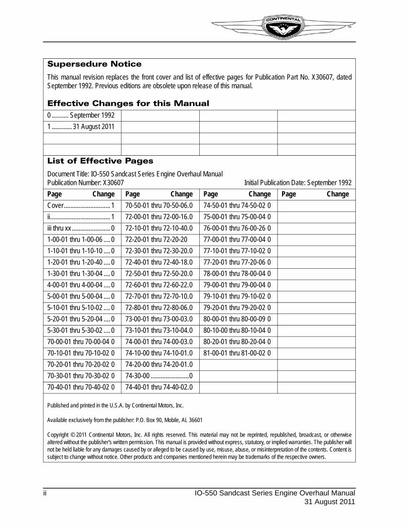
Supersedure Notice
This manual revision replaces the front cover and list of effective pages for Publication Part No. X30607, datedSeptember 1992. Previous editions are obsolete upon release of this manual.
Effective Changes for this Manual0 .......... September 1992
1 ............ 31 August 2011
List of Effective Pages
Document Title: IO-550 Sandcast Series Engine Overhaul ManualPublication Number: X30607 Initial Publication Date: September 1992
Page Change Page Change Page Change Page Change
Cover............................ 1 70-50-01 thru 70-50-06.0 74-50-01 thru 74-50-02 0
ii.................................... 1 72-00-01 thru 72-00-16.0 75-00-01 thru 75-00-04 0
iii thru xx ....................... 0 72-10-01 thru 72-10-40.0 76-00-01 thru 76-00-26 0
1-00-01 thru 1-00-06 .... 0 72-20-01 thru 72-20-20 77-00-01 thru 77-00-04 0
1-10-01 thru 1-10-10 .... 0 72-30-01 thru 72-30-20.0 77-10-01 thru 77-10-02 0
1-20-01 thru 1-20-40 .... 0 72-40-01 thru 72-40-18.0 77-20-01 thru 77-20-06 0
1-30-01 thru 1-30-04 .... 0 72-50-01 thru 72-50-20.0 78-00-01 thru 78-00-04 0
4-00-01 thru 4-00-04 .... 0 72-60-01 thru 72-60-22.0 79-00-01 thru 79-00-04 0
5-00-01 thru 5-00-04 .... 0 72-70-01 thru 72-70-10.0 79-10-01 thru 79-10-02 0
5-10-01 thru 5-10-02 .... 0 72-80-01 thru 72-80-06.0 79-20-01 thru 79-20-02 0
5-20-01 thru 5-20-04 .... 0 73-00-01 thru 73-00-03.0 80-00-01 thru 80-00-09 0
5-30-01 thru 5-30-02 .... 0 73-10-01 thru 73-10-04.0 80-10-00 thru 80-10-04 0
70-00-01 thru 70-00-04 0 74-00-01 thru 74-00-03.0 80-20-01 thru 80-20-04 0
70-10-01 thru 70-10-02 0 74-10-00 thru 74-10-01.0 81-00-01 thru 81-00-02 0
70-20-01 thru 70-20-02 0 74-20-00 thru 74-20-01.0
70-30-01 thru 70-30-02 0 74-30-00 .......................0
70-40-01 thru 70-40-02 0 74-40-01 thru 74-40-02.0
Published and printed in the U.S.A. by Continental Motors, Inc.
Available exclusively from the publisher: P.O. Box 90, Mobile, AL 36601
Copyright © 2011 Continental Motors, Inc. All rights reserved. This material may not be reprinted, republished, broadcast, or otherwisealtered without the publisher's written permission. This manual is provided without express, statutory, or implied warranties. The publisher willnot be held liable for any damages caused by or alleged to be caused by use, misuse, abuse, or misinterpretation of the contents. Content issubject to change without notice. Other products and companies mentioned herein may be trademarks of the respective owners.
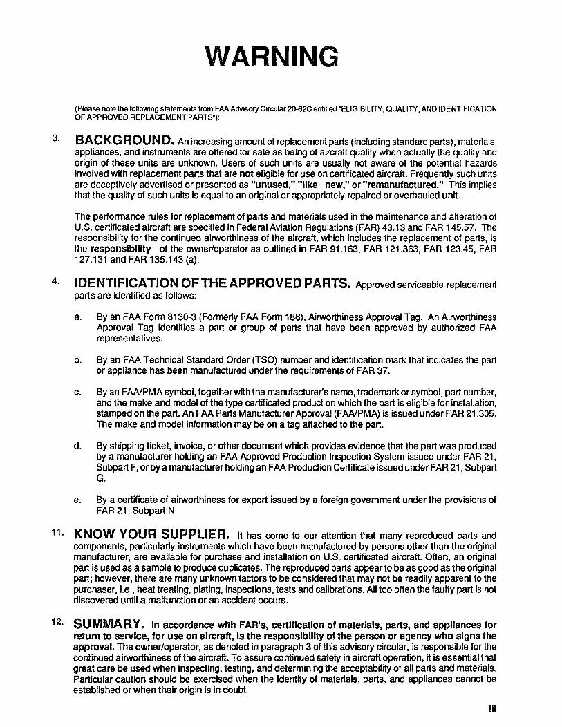
WARNING
(Please note the following statements from FAA Advisory Circular 20-62C entitled "ELIGIBILITY, QUALITY, AND IDENTIFICATION OF APPROVED REPLACEMENT PARTS"):
3. BACKG ROUND. An increasing amount of replacement parts (including standard parts), materials, appliances, and instruments are offered for sale as being of aircraft quality when actually the quality and origin of these units are unknown. Users of such units are usually not aware of the potential hazards involved with replacement parts that are not eligible for use on certificated aircraft. Frequently such units are deceptively advertised or presented as "unused," "like new," or "remanufactured." This implies that the quality of such units is equal to an original or appropriately repaired or overhauled unit.
The performance rules for replacement of parts and materials used in the maintenance and alteration of U.S. certificated aircraft are specified in Federal Aviation Regulations (FAR) 43.13 and FAR 145.57. The responsibility for the continued airworthiness of the aircraft, which includes the replacement of parts, is the responsibility of the owner/operator as outlined in FAR 91.163, FAR 121.363, FAR 123.45, FAR 127.131 and FAR 135.143 (a).
4. IDENTIFICATION OF THE APPROVED PARTS. Approved serviceable replacement parts are identified as follows:
a. By an FAA Form 8130-3 (Formerly FAA Form 186), Airworthiness Approval Tag. An Airworthiness Approval Tag identifies a part or group of parts that have been approved by authorized FAA representatives.
b. By an FAA Technical Standard Order (TSO) number and identification mark that indicates the part or appliance has been manufactured under the requirements of FAR 37.
c. By an FAAIPMA symbol, together with the manufacturer's name, trademark or symbol, part number, and the make and model of the type certificated product on which the part is eligible for installation, stamped on the part. An FAA Parts Manufacturer Approval (FAAIPMA) is issued under FAR 21.305. The make and model information may be on a tag attached to the part.
d. By shipping ticket, invoice, or other document which provides evidence that the part was produced by a manufacturer holding an FAA Approved Production Inspection System issued under FAR 21, Subpart F, or by a manufacturer holding an FAA Production Certificate issued under FAR 21 , Subpart G.
e. By a certificate of airworthiness for export issued by a foreign govemment under the provisions of FAR 21, Subpart N.
11. KNOW YOUR SUPPLIER. It has come to our attention that many reproduced parts and components, particularly instruments which have been manufactured by persons other than the original manufacturer, are available for purchase and installation on U.S. certificated aircraft. Often, an original part is used as a sample to produce duplicates. The reproduced parts appear to be as good as the original part; however, there are many unknown factors to be considered that may not be readily apparent to the purchaser, i.e., heat treating, plating, inspections, tests and calibrations. All too often the faulty part is not discovered until a malfunction or an accident occurs.
12. SUMMARY. In accordance with FAR's, certification of materials, parts, and appliances for return to service, for use on aircraft, Is the responsibility of the person or agency who signs the approval. The owner/operator, as denoted in paragraph 3 of this adviSOry circular, is responsible for the continued airworthiness of the aircraft. To assure continued safety in aircraft operation, it is essential that great care be used when inspecting, testing, and determining the acceptability of all parts and materials. Particular caution should be exercised when the identity of materials, parts, and appliances cannot be established or when their origin is in doubt.
III
iv
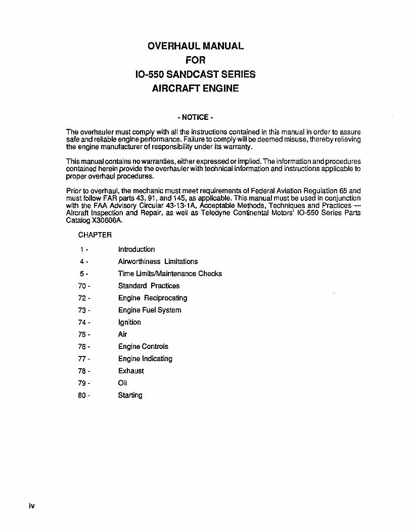
OVERHAUL MANUAL
FOR
10-550 SANDCAST SERIES
AIRCRAFT ENGINE
• NOTICE-
The overhauler must comply with all the instructions contained in this manual in order to assure safe and reliable engine performance. Failure to comply will be deemed misuse, thereby relieving the engine manufacturer of responsibility under its warranty.
This manual contains no warranties, either expressed or implied. The information and procedures contained herein provide the overhauler with technical information and instructions applicable to proper overhaul procedures.
Prior to overhaul, the mechanic must meet requirements of Federal Aviation Regulation 65 and must follow FAR parts 43, 91, and 145, as applicable. This manual must be used in conjunction
. with the FAA Advisory Circular 43-13-1A, Acceptable Methods, Techniques and PracticesAircraft Inspection and Repair, as well as Teledyne Continental Motors' 10-550 Series Parts Catalog X30606A.
CHAPTER
1 - Introduction
4- Airworthiness Limitations
5- Time Umits/Maintenance Checks
70 - Standard Practices
72 - Engine Reciprocating
73 - Engine Fuel System
74 - Ignition
75 - Air
76 - Engine Controls
77 - Engine Indicating
78 - Exhaust
79 - Oil
80 - Starting
INTRODUCTION
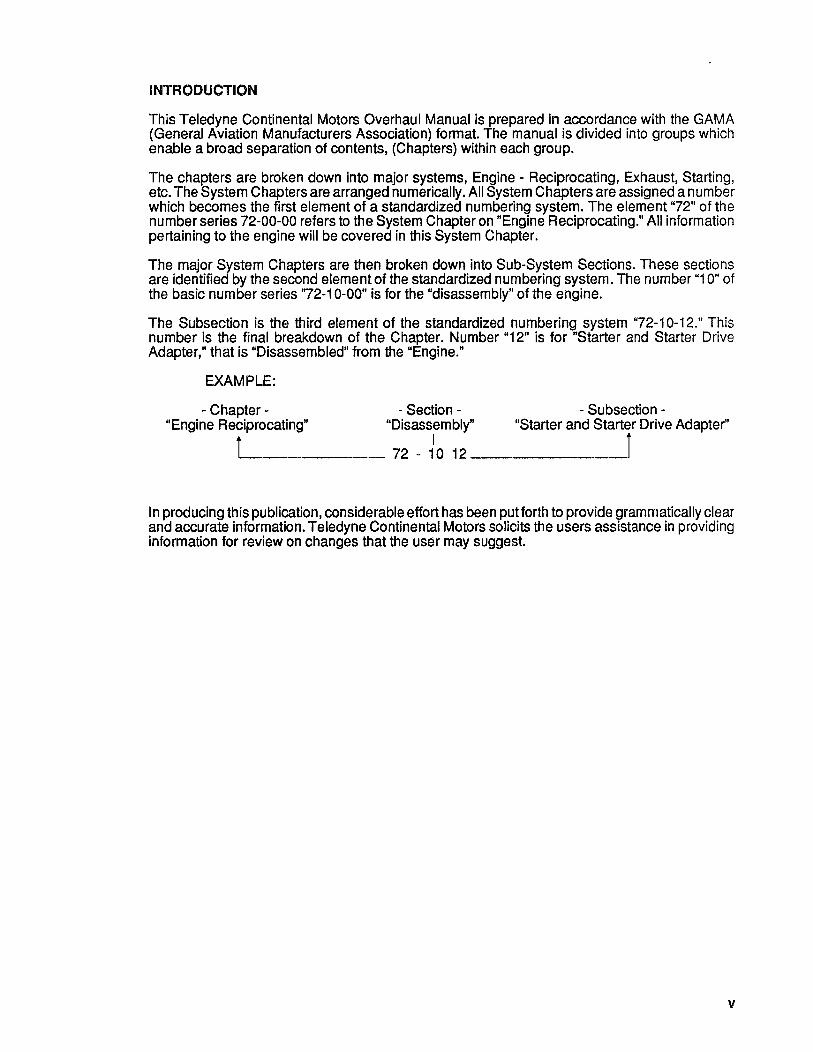
This Teledyne Continental Motors Overhaul Manual is prepared in accordance with the GAMA (General Aviation Manufacturers Association) format. The manual is divided into groups which enable a broad separation of contents, (Chapters) within each group.
The chapters are broken down into major systems, Engine - Reciprocating, Exhaust, Starting, etc. The System Chapters are arranged numerically. All System Chapters are assigned a number which becomes the first element of a standardized numbering system. The element "72" of the number series 72-00-00 refers to the System Chapter on "Engine Reciprocating." All information pertaining to the engine will be covered in this System Chapter.
The major System Chapters are then broken down into Sub-System Sections. These sections are identified by the second element of the standardized numbering system. The number "1 0" of the basic number series '72-10-00" is for the "disassembly" of the engine.
The Subsection is the third element of the standardized numbering system "72-10-12." This number is the final breakdown of the Chapter. Number "12" is for "Starter and Starter Drive Adapter," that is "Disassembled" from the "Engine."
EXAMPLE:
- Chapter - - Section - - Subsection -"Engine Reciprocating" "Disassembly" "Starter and Starter Drive Adapter"
il.-______ 72 - 110 12 ______ --1J
In producing this publication, considerable effort has been put forth to provide grammatically clear and accurate information. Teledyne Continental Motors solicits the users assistance in providing information for review on changes that the user may suggest.
v

vi
TABLE OF CONTENTS
Section Page
ii Current Status of Pages ................................ ii iii Warning. . . . . . . . . . . . . . . . . . . . . . . . . . . . . . . . . . . . . . . . .iii iv Notice. . . . . . . . . . . . . . . . . . . . . . . . . . . . . . . . . . . . . . . . . iv v Introduction ....................................... v vi Table of Contents . . . . . . . . . . . . . . . . . . . . . . . . . . . . . . . . . . . vi xiv List of Illustrations . . . . . . . . . . . . . . . . . . . . . . . . . . . . . . . . . . . xiv xix List of Charts ..................................... xix
CHAPTER 1 INTRODUCTION
1-00-00 SCOPE..................................... 1-00-03 1-00-01 Related Publications . . . . . . . . . . . . . . . . . . . . . . . . . . . . . 1-00-03 1-00-02 Service Bulletins .... . . . . . . . . . . . . . . . . . . . . . . . . . . . 1-00-04 1-00-03 Service Reports And Inquiries . . . . . . . . . . . . . . . . . . . . . . . . 1-00-04 1-00-04 100% Replacement Parts .......................... 1-00-05
1-10-00 DEFINITIONS & ABBREVIATIONS ...................... 1-10-01 1-10-01 Abbreviation / Symbols ........................... 1-10-01 1-10-02 Definitions. . . . . . . . . . . . . . . . . . . . . . . . . . . . . . . . . . 1-10-02 1-10-03 Description Of Engine Model Code ............. .. . . . . . . . 1-10-06 1-10-04 Basic Design Features . . . . . . . . . . . . . . . . . . . . . . . . . . . . 1-10-07
1-20-00 TOOLS..................................... 1-20-01 1-20-01 Special Tools . . . . . . . . . . . . . . . . . . . . . . . . . . . . . . . . . 1-20-01
1-30-00 APPLICATION CHART SEALANTS/LUBRICANTS .............. 1-30-01 1-30-01 Product List ................................. 1-30-01
CHAPTER 4 AIRWORTHINESS LIMITATIONS
4-00-00 AIRWORTHINESS LIMITATIONS ....................... 4-00-01
CHAPTER 5 TIME LIMITS/MAINTENANCE
CHECK
5-00-00 GENERAL ................................... 5-00-03 5-10-00 TIME LIMITS/INSPECTION PROGRAM . . . . . . . . . . . . . . . . . . . . 5-10-01 5-20-00 SCHEDULED MAINTENANCE . . . . . . . . . . . . . . . . . . . . . . . . . 5-20-01 5-20-01 Preflight Inspection .............................. 5-20-01 5-20-02 50 Hour Inspection . . . . . . . . . . . . . . . . . . . . . . . . . . . . . . 5-20-01 5-20-03 100 Hour Inspection ......•...................... 5-20-01 5-30-00 UNSCHEDULED MAINTENANCE ....................... 5-30-01
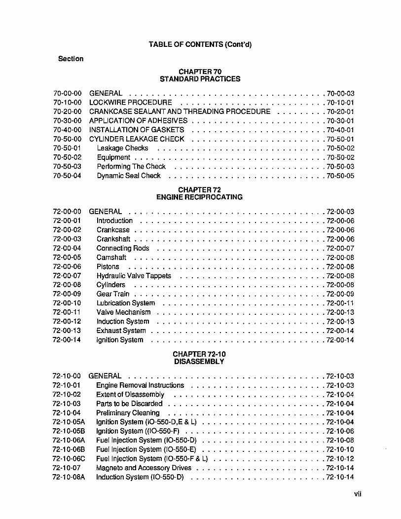
TABLE OF CONTENTS (Cont'd)
Section
CHAPTER 70 STANDARD PRACTICES
70-00-00 GENERAL ................................... 70-00-03 70-10-00 LOCKWIRE PROCEDURE .......................... 70-10-01 70-20-00 CRANKCASE SEALANT AND THREADING PROCEDURE ......... 70-20-01 70-30-00 APPLICATION OF ADHESIVES ........................ 70-30-01 70-40-00 INSTALLATION OF GASKETS ........................ 70-40-01 70-50-00 CYLINDER LEAKAGE CHECK ........................ 70-50-01 70-50-01 Leakage Checks .............................. 70-50-02 70-50-02 Equipment. . . . . . . . . . . . . . . . . . . . . . . . . . . . . . . . . . 70-50-02 70-50-03 Performing The Check ........................... 70-50-03 70-50-04 Dynamic Seal Check ............................ 70-50-05
72-00-00 72-00-01 72-00-02 72-00-03 72-00-04 72-00-05 72-00-06 72-00-07 72-00-08 72-00-09 72-00-10 72-00-11 72-00-12 72-00-13 72-00-14
CHAPTER 72 ENGINE RECIPROCATING
GENERAL .................................. . 72-00-03 Introduction ................................. 72-00-06 Crankcase . . . . . . . . . . . . . . . . . . . . . . . . . . . . . . . . . . 72-00-06 Crankshaft . . . . . . . . . . . . . . . . . . . . . . . . . . . . . . . . . . 72-00-06 Connecting Rods .............................. 72-00-07 Camshaft .................................. 72-00-08 Pistons' ................................... 72-00-08 Hydraulic Valve Tappets .......................... 72-00-08 Cylinders .................................. 72-00-08 Gear Train . . . . . . . . . . . . . . . . . . . . . . . . . . . . . . . . . . 72-00-09 Lubrication System ............................. 72-00-11 Valve Mechanism .............................. 72-00-13 Induction System .............................. 72-00-13 Exhaust System . . . . . . . . . . . . . . . . . . . . . . . . . . . . . . . 72-00-14 Ignition System ............................... 72-00-14
CHAPTER 72·10 DISASSEMBL Y
72-10-00 GENERAL ................................... 72-10-03 72-10-01 72-10-02 72-10-03 72-10-04 72-10-05A 72-10-058 72-10-06A 72-10-068 72-10-06C 72-10-07 72-10-08A
Engine Removal Instructions ........................ 72-10-03 Extent of Disassembly ........................... 72-10-04 Parts to be Discarded ............................ 72-10-04 Preliminary Cleaning .•.......................... 72-10-04 Ignition System (10-550-D,E & L) ...................... 72-10-04 Ignition System «10-550-F) ......................... 72-10-06 Fuel Injection System (10-550-D) ...................... 72-10-08 Fuel Injection System (10-550-E) .•.................... 72-10-10 Fuel Injection System (10-550-F & L) .................... 72-10-12 Magneto and Accessory Drives . . . . . . . . . . . . . . . . . . . . . . . 72-10-14 Induction System (10-550-D) ........................ 72-10-14
vii
viii
TABLE OF CONTENTS (Cont'd)
Section
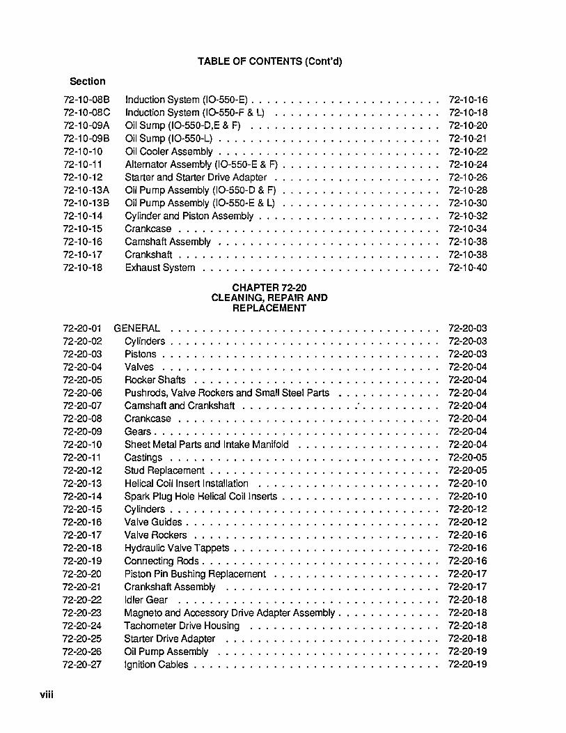
72-10-088 Induction System (10-550-E). . . . . . . . . . . . . . . . . . . . . . .. 72-10-16 72-10-08C Induction System (10-550-F & L) ..................... 72-10-18 72-10-09A Oil Sump (10-550-D,E & F) ........................ 72-10-20 72-10-098 Oil Sump (10-550-L) . . . . . . . . . . . . . . . . . . . . . . • . . . .. 72-10-21 72-10-10 Oil Cooler Assembly. . . . . . . . . . . . . . . . . . . . . . . . . . .. 72-10-22 72-10-11 Alternator Assembly (10-550-E & F) . . . . . . . . . . . . . . . . . . .. 72-10-24 72-10-12 StarterandStarterDriveAdapter ..................... 72-10-26 72-10-13A Oil Pump Assembly (10-550-D & F) . . . . . . . . . . . . . . . . . . .. 72-10-28 72-10-138 Oil Pump Assembly (10-550-E & L) . . . . . . . . . . . . . . . . . . .. 72-10-30 72-10-14 Cylinder and Piston Assembly. . . . . . . . . . . . . . . . . . . . . .. 72-10-32 72-10-15 Crankcase. . . . . . . . . . . . . . . . . . . . . . . . . . . . . . . .. 72-10-34· 72-10-16 Camshaft Assembly . . . . . . . . . . . . . . . . . . . . . . . . . . .. 72-10-38 72-10-17 Crankshaft. . . . . . . . . . . . . . . . . . . . . . . . . . . . . . . .. 72-10-38 72-10-18
72-20-01 72-20-02 72-20-03 72-20-04 72-20-05 72-20-06 72-20-07 72-20-08 72-20-09 72-20-10 72-20-11 72-20-12 72-20-13 72-20-14 72-20-15 72-20-16 72-20-17 72-20-18 72-20-19 72-20-20 72-20-21 72-20-22 72-20-23 72-20-24 72-20-25 72-20-26 72-20-27
Exhaust System
GENERAL
CHAPTER 72-20 CLEANING, REPAIR AND
REPLACEMENT
Cylinders ................................. . Pistons .................................. . Valves .................................. . Rocker Shafts . . . . . . . . . . . . . . . . . . . . . . . . . . . . . . . Pushrods, Valve Rockers and Small Steel Parts . . . . . . . . . . . . . Camshaft and Crankshaft . . . . . . . . . . . . . . : . . . . . . . . . .
72-10-40
72-20-03 72-20-03 72-20-03 72-20-04 72-20-04 72-20-04 72-20-04
Crankcase . . . . . . . . . . . . . . . . . . . . . . . . . . . . . . . .. 72-20-04 Gears. . . . . . . . . . . . . . . . . . . . . . . . . . . . . . . . . . .. 72-20-04 Sheet Metal Parts and Intake Manifold ..... .. . . . . . . . . . . .. 72-20-04 Castings . . . . . . . . . . . . . . . . . . . . . . . . . . . . . . . . .. 72-20-05 Stud Replacement . . . . . . . . . . . . . . . . . . . . . . . . . . . .. 72-20-05 Helical Coil Insert Installation ....................... 72-20-10 Spark Plug Hole Helical Coil Inserts . . . . . . . . . . . . . . . . . . .. 72-20-10 Cylinders. . . . . . . . . . . . . . . . . . . . . . . . . . . . . . . . .. 72-20-12 Valve Guides. . . . . . . . . . . . . . . . . . . . . . . . . . . . . . .. 72-20-12 Valve Rockers . . . . . . . . . . . . . . . . . . . . . . . . . . . . . .. 72-20-16 Hydraulic Valve Tappets. . . . . . . . . . . . . . . . . . . . . . . . .. 72-20-16 Connecting Rods. . . . . . . . . . . . . . . . . . . . . . . . . . . . .. 72-20-16 Piston Pin 8ushing Replacement . . . . . . . . . . . . . . . . . . . .. 72-20-17 Crankshaft Assembly ........................... 72-20-17 Idler Gear ................................. 72-20-18 Magneto and Accessory Drive Adapter Assembly. . . . . . . . . . . .. 72-20-18 Tachometer Drive Housing ........................ 72-20-18 Starter Drive Adapter ........................... 72-20-18 Oil Pump Assembly ............................ 72-20-19 Ignition Cables. . .. . . . . . . . . . . . . . . . . . . . . . . . . . .. 72-20-19

Section
TABLE OF CONTENTS (Cont'd)
CHAPTER 72-30 INSPECTION
72-30-01 GENERAL ............... . . 72-30-03 72-30-02 72-30-03 72-30-04 72-30-05 72-30-06 72-30-07 72-30-08 72-30-09 72-30-10 72-30-11 72-30-12 72-30-13 72-30-14 72-30-15
72-40-01 72-40-02 72-40-03 72-40-04 72-40-05 72-40-06 72-40-07 72-40-08 72-40-09 72-40-10 72-40-11 72-40-12 72-40-13 72-40-14 72-40-15
Visual Inspection ............................. . 72-30-04 Magnetic Particle Inspection ........................ 72-30-04 Crankshaft Ultrasonic Inspection . . . . . . . . . . . . . . . . . . . . . . 72-30-06 Florescent Particle Inspection . . . . . . . . . . . . . . . . . . . . . . . . 72-30-06 Dimensionallnspection . . . . . . . . . . . . . . . . . . . . . . . . . . . 72-30-06 Dimensional Limits ... . . . . . . . . . . . . . . . . . . . . . . . . . . 72-30-06 Table of Limits. . . . . . . . . . . . . . . . . . . . . . . . . . . . . . . . 72-30-06 Original Dimension ..................... . . . . . . . . 72-30-06 New Parts and Service Limits . . . . . . . . . . . . . . . . . . . .. . 72-30-06 Critical New Parts Dimensions ....................... 72-30-18 Protective Coating. . . . . . . . . . . . . . . . . . . . . . . . . . . . . . 72-30-19 Application of Alodine . . . . . . . . .. ................. 72-30-19 Repair of Alodized Surfaces ........................ 72-30-20 Enamel Coatings .. . . . . . . . . . . . . . . . . . . . . . . . . 72-30-20
CHAPTER 72-40 SPECIFIC INSPECTION
Crankcase .................................. 72-40-03 Crankshaft. . . . . . . . . . . . . . . . . . . . . . . . . . . . . . . . 72-40-03 Crankshaft, Counterweight Pins, and Bushings .............. 72-40-03 Camshaft . . . . . . . . . . . . . . . . . . . . . . . . . . . . . . . . . . 72-40-04 Connecting Rods . . . . . . . . . . . . . . . . . . . . . . . . . . . . . . 72-40-04 Gears . . . . . . . . . . . . . . . . . . . . . . . . . . . . . . . . . . . . 72-40-04 Pistons and Rings . . . . . . . . . . . . . . . . . . . . . . . . . . . . . . 72-40-04 Cylinders .................................. 72-40-06 Hydraulic Valve Tappets .......................... 72-40-06 Intake Tubes ................................ 72-40-07 Lubrication System ............................. 72-40-07 Fuel Injection System . . . . . . . . . . . . . . . . . . . . . . . . . . . . 72-40-07 Ignition System .' . . . . . . . . . . . . . . . . . . . . . . . . . . . 72-40-07 Exhaust System. . . . . . . . . . . . . . . . . . . . . ....... 72-40-08 Inspection chart . . . . . . . . . . . . . . . . . . . . . . . . . . . . . . . 72-40-09
CHAPTER 72-50 ASSEMBLY OF SUBASSEMBLIES
72-50-01 GENERAL . 72-50-03 72-50-01 A-D Table of Tightening Torques ........................ 72-50-03 72-50-02A Oil Pump Assembly (10-550-0 & F) . . . . . . . . . . . . . . . . . . . . . 72-50-09 72-50-02B Oil Pump Assembly (10-550-E & L) . . . . . . . . . . . . . . . . . . . . . 72-50-09 72-50-03 Starter and Drive Assembly . . . . . . . . . . . . . . . . . . . . . . . . . 72-50-10 72-50-04 Cylinder Assembly ............................. 72-50-10 72-50-05 Piston and Ring Assemblies ........................ 72-50-11
ix

x
Section
72-50-06 72-50-07 72-50-08 72-50-09 72-50-10 72-50-11 72-50-12 72-50-13
72-60-01 72-60-02 72-60-03 72-60-04 72-60-05A 72-60-05B 72-60-06 72-60-07 72-60-08 72-60-09 72-60-10 72-60-11A 72-60-11 B 72-60-12A 72-60-12B 72-60-12C 72-60-13A 72-60-13B 72-60-13C 72-60-14 72-60-15 72-60-16 72-60-17 72-60-18
72-70-01 72-70-02 72-70-03 72-70-04 72-70-05 72-70-06 72-70-07
TABLE OF CONTENTS (Cont'd)
Pushrod Housing. . . . . . . . . . . . . . . . . . . . . . . . . . . . .. 72-50-11 Crankshaft and Connecting Rods . . . . . . . . . . . . . . . .. 72-50-12 Camshaft . . . . . . . . . . . . . . . . . . . . . . . . . . . . . . . . .. 72-50-13 Crankcase ...................... . Fuel Pump. . . . . . . . . . . ... . Fuel Control Valve . . . . . . . . . . . . . . . . Fuel Manifold Valve . . . . . . . . . . . . . . . Fuel Control Valve and Throttle Assembly ...
General ....... .
CHAPTER 72-60 FINAL ASSEMBLY
Crankcase ................................ . Crankcase Thru Bolt Installation and Torquing Sequence ....... . Cylinders and Pistons . . . . . . . . . . . . . . . . . . . . . . . . . . . Oil Pump (10-550-0 & F) ......................... . Oil Pump (10-550-E & L) . . . . . . . . . . . . . . . . . . . . . . . Starter Drive Adapter .......................... . Alternator Assembly . . . . . . . . . . . . . . . . . . . . . . . . . . . . Magneto and Accessory Drive Adapters. .. . . . . . . . . . . . . . Oil Cooler ................................ . Valve Mechanism ............................ . Oil Sump (10-550-D,E & F) ....................... . Oil Sump (10-550-L) . . . . . . . . . . . . . . . . . . . . . . . . . Induction System (10-550-0) .. . ................ . Induction System (10-550-E). . . . . . . . . . . . . . . . . Induction System (10-550-F & L) . . . . . . . . . . . . . . . . . . Fuel Injection System (10-550-0) .................... . Fuel Injection System (10-550-E) .................... . Fuel Injection System (10-550-F & L) .................. . Magneto Drive Gears .......................... . Placing Crankshaft in Timing Position . . . . . . . . . . . . . . . . . . . Magnetos ................................. .
Ignition Harness . . . . . . . . . . . . . . . . . . . . . . . . . . . . . . Exhaust System . . . . . . . . . . . . . . . . . . . . . . . . . . . . . .
CHAPTER 72-70 TESTING AFTER OVERHAUL
TestStand ................. . TestClub .................. . Cooling Air Scoop . . . . . . . . . . . . . . Induction Air Intake ......... . Exhaust System . . . . . . . . . . . . Controls ............... . Electrical Wiring . . . . . . . . . . . .
72-50-13 72-50-14 72-50-15 72-50-15 72-50-20
72-60-03 72-60-03 72-60-06 72-60-08 72-60-09 72-60-10 72-60-11 72-60-11 72-60-12 72-60-12 72-60-12 72-60-14 72-60-15 72-60-15 72-60-15 72-60-16 72-60-17 72-60-17 72-60-18 72-60-18 72-60-19 72-60-20 72-60-20 72-60-21
72-70-03 72-70-03 72-70-03 72-70-03 72-70-03 72-70-04 72-70-04

TABLE OF CONTENTS (Cont'd)
Section
72-70-08 Instruments ................................. 72-70-04 72-70-09 Breather ................................... 72-70-04 72-70-10 Fuel System ................................. 72-70-04 72-70-11 Governor Pad Cover ............................ 72-70-04 72-70-12 Engine Test ................................. 72-70-05 72-70-13 Starting Procedure ............................. 72-70-05 72-70-14A Overhaul Test Run ............................. 72-70-06 72-70-14B Oil Consumption Determination ....................... 72-70-07 72-70-14C Test Operating Limits ............................ 72-70-08 72-70-15 Test Flight .................................. 72-70-09
72-80-01 72-80-02 72-80-03 72-80-04
73-00-00 73-10-00 73-10-01 73-10-02 73-10-03
CHAPTER 72-80 ENGINE PRESERVATION
General . . . . . . . . . . . . . . . . . . . . . . . . . . . . . . . . . . . 72-80-03 Flyable Storage . . . . . . . . . . . . . . . . . . . . . . . . . . . . . . . 72-80-03 Temporary Storage . . . . . . . . . . . . . . . . . . . . . . . . . . . . . 72-80-04 Indefinite Storage . . . . . . . . . . . . . . . . . . . . . . . . . . . . . . 72-80-05
CHAPTER 73 ENGINE FUEL SYSTEM
Engine Fuel System. . . . . . . . . . . . . . . . . . . . . . . . . . . . . 73-00-03 Set Up Procedure .............................. 73-10-00 Naturally Aspirated Engines ......................... 73-10-00 Fuel Systems Pressures and Flow Values ................. 73-10-01 Fuel System Troubleshooting Chart .................... 73-10-02
CHAPTER 74 IGNITION
(TCM IGNITION SYSTEM)
74-00-00 GENERAL ................................... 74-00-03 74-10-01 74-10-02 74-20-00 74-30-00 74-40-01 74-40-02 74-50-00
Magneto Installation . . . . . . . . . . . . . . . . . . . . . . . . . . . . . 74-10-00 Harness Assembly Installation ....................... 74-10-00 Ignition Troubleshooting. . . . . . . . . . . . . . . . . . . . . . . . . . . 74-20-00 General . . . . . . . . . . . . . . . . . . . . . . . . . . . . . . . . . . . 74-30-00 Magneto Installation . . . . . . . . . . . . . . . . . . . . . . . . . . . . . 74-40-01 Harness Assembly Installation .............. . . . . . . . . . 74-40-02 Ignition Troubleshooting. . . . . . . . . . . . . . . . . . . . . . . . . . . 74-50-01
CHAPTER 75 AIR
75-00-00 GENERAL ................................... 75-00-03
xl
xii
Section
TABLE OF CONTENTS (Cont'd)
CHAPTER 76 ENGINE CONTROLS
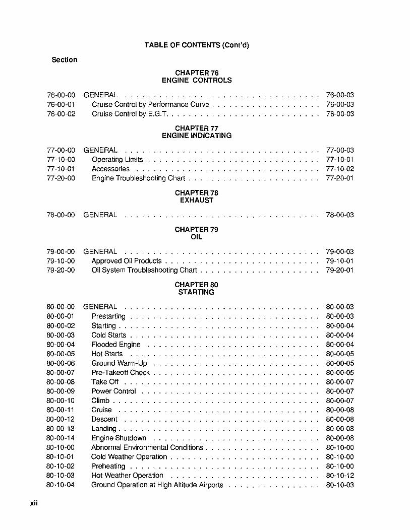
76-00-00 GENERAL ... 76-00-01 76-00-02
Cruise Control by Performance Curve .......... . Cruise Control by E.G.T .................. .
CHAPTER 77 ENGINE INDICATING
77-00-00 GENERAL ... 77-10-00 77-10-01 77-20-00
Operating Limits ....................... . Accessories . . . . . . . . . . . . . . . . . . . . . . . . Engine Troubleshooting Chart . . . . . . . . . . . . . . . . .
CHAPTER 78 EXHAUST
76-00-03 76-00-03 76-00-03
77-00-03 77-10-01 77-10-02 77-20-01
78-00-00 GENERAL ....... . . . . . . . .. 78-00-03
CHAPTER 79 OIL
79-00-00 GENERAL ......................... . 79-10-00 79-20-00
80-00-00 80-00-01 80-00-02 80-00-03 80-00-04 80-00-05 80-00-06 80-00-07 80-00-08 80-00-09 80-00-10 80-00-11 80-00-12 80-00-13 80-00-14 80-10-00 80-10-01 80-10-02 80-10-03 80-10-04
Approved Oil Products . . . . . . . . . . . . . . . . . . . Oil System Troubleshooting Chart . . . . . . . . . . . . .
GENERAL ...
CHAPTER 80 STARTING
Prestarting . . . . . . . . . . . . . . . . . . . . . Starting. . . . . ................. . Cold Starts .......................... . Flooded Engine ... . Hot Starts ...... . Ground Warm-Up . . . Pre-Takeoff Check .. . Take Off ....... . Power Control . . . . . Climb ......... . Cruise ............................ . Descent ........................... . Landing ............................ . Engine Shutdown ...................... . Abnormal Environmental Conditions. . . . . . . . . . . . . . Cold Weather Operation . . . . . . . . . . . . . . . . . . . . Preheating . . . . . . . . . . . . . . . . . . . . . . . . . . . Hot Weather Operation ................... . Ground Operation at High Altitude Airports ......... .
79-00-03 79-10-01 79-20-01
80-00-03 80-00-03 80-00-04 80-00-04 80-00-04 80-00-05 80-00-05 80-00-05 80-00-07 80-00-07 80-00-07 80-00-08 80-00-08 80-00-08 80-00-08 80-10-00 80-10-00 80-10-00 80-10-12 80-10-03

Section
80-20-00 80-20-01 80-20-02 80-20-03 80-20-04 80-20-05 80-20-06
TABLE OF CONTENTS (Cont'd)
Emergency Procedures . . . . . . . . . . . . . . . . . . . . . . . . . . . 80-20-01 Engine Fire During Start .......................... 80-20-01 Engine Roughness ............................. 80-20-01 High Cylinder Head Temperatures ..................... 80-20-02 High Oil Temperature . . . . . . . . . . . . . . . . . . . . . . . . . . . . 80-20-02 Low Oil Pressure .............................. 80-20-02 In-Flight Restarting ............................. 80-20-02
CHAPTER 81 TURBINES
81-00-00 GENERAL (Not Applicable) .......................... 81-00-01
xiii
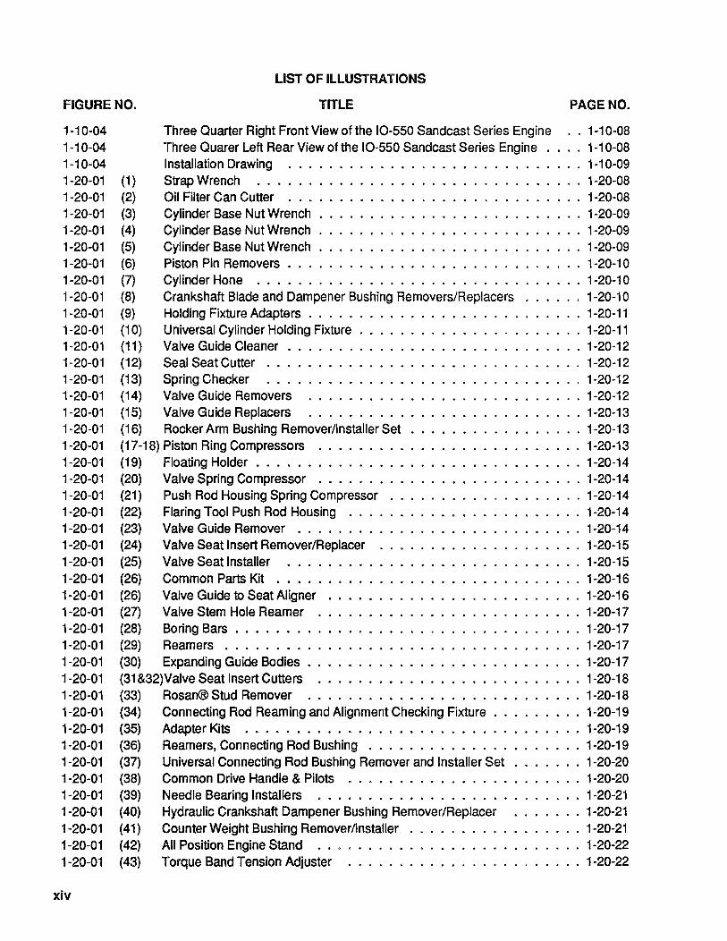
FIGURE NO.
LIST OF ILLUSTRATIONS
TITLE PAGE NO.
1-10-04 Three Quarter Right Front View of the 10-550 Sandcast Series Engine .. 1-10-08 1-10-04 Three Quarer Left Rear View of the 10-550 Sandcast Series Engine . . . . 1-10-08 1-10-04 Installation Drawing ............................. 1-10-09 1-20-01 (1) Strap Wrench ................................ 1-20-08 1-20-01 (2) Oil Filter Can Cutter ............................. 1-20-08 1-20-01 (3) Cylinder Base Nut Wrench . . . . . . . . . . . . . . . . . . . . . . . . . . 1-20-09 1-20-01 (4) Cylinder Base Nut Wrench .......................... 1-20-09 1-20-01 (5) Cylinder Base Nut Wrench . . . . . . . . . . . . . . . . . . . . . . . . . . 1-20-09 1-20-01 (6) Piston Pin Removers . . . . . . . . . . . . . . . . . . . . . . . . . . . . . 1-20-10 1-20-01 (7) Cylinder Hone ................................ 1-20-10 1-20-01 (8) Crankshaft Blade and Dampener Bushing Removers/Replacers ...... 1-20-10 1-20-01 (9) Holding Fixture Adapters . . . . . . . . . . . . . . . . . . . . . . . . . . . 1-20-11 1-20-01 (10) Universal Cylinder Holding Fixture . . . . . . . . . . . . . . . . . . . . . . 1-20-11 1-20-01 (11) Valve Guide Cleaner . . . . . . . . . . . . . . . . . . . . . . . . . . . . . 1-20-12 1-20-01 (12) Seal Seat Cutter ............................... 1-20-12 1-20-01 (13) Spring Checker ............................... 1-20-12 1-20-01 (14) Valve Guide Removers ........................... 1-20-12 1-20-01 (15) Valve Guide Replacers ........................... 1-20-13 1-20-01 (16) Rocker Arm Bushing Remover/Installer Set ................. 1-20-13 1-20-01 (17-18) Piston Ring Compressors .......................... 1-20-13 1-20-01 (19) Floating Holder . . . . . . . . . . . . . . . . . . . . . . . . . . . . . . . . 1-20-14 1-20-01 (20) Valve Spring Compressor .......................... 1-20-14 1-20-01 (21) Push Rod Housing Spring Compressor ................... 1-20-14 1-20-01 (22) Flaring Tool Push Rod Housing ....................... 1-20-14 1-20-01 (23) Valve Guide Remover ............................ 1-20-14 1-20-01 (24) Valve Seatlnsert Remover/Replacer .................... 1-20-15 1-20-01 (25) Valve Seat Installer ............................. 1-20-15 1-20-01 (26) Common Parts Kit •............................. 1-20-16 1-20-01 (26) Valve Guide to Seat Aligner ............ . . . . . . . . . . . . . 1-20-16 1-20-01 (27) Valve Stem Hole Reamer .......................... 1-20-17 1-20-01 (28) Boring Bars . . . . . . . . . . . . . . . . . . . . . . . . . . . . . . . . . . 1-20-17 1-20-01 (29) Reamers................................... 1-20-17 1-20-01 (30) Expanding Guide Bodies . . . . . . . . . . . . . . . . . . . . . . . . . . . 1-20-17 1-20-01 (31 &32) Valve Seat Insert Cutters .......................... 1-20-18 1-20-01 (33) Rosan® Stud Remover ........................... 1-20-18 1-20-01 (34) Connecting Rod Reaming and Alignment Checking Fixture . . . . . . . . . 1-20-19 1-20-01 (35) Adapter Kits ................................. 1-20-19 1-20-01 (36) Reamers, Connecting Rod Bushing . . . . . . . . . . . . . . . . . . . . . 1-20-19 1-20-01 (37) Universal Connecting Rod Bushing Remover and Installer Set . . . . . . . 1-20-20 1-20-01 (38) Common Drive Handle & Pilots ....................... 1-20-20 1-20-01 (39) Needle Bearing Installers .......................... 1-20-21 1-20-01 (40) Hydraulic Crankshaft Dampener Bushing Remover/Replacer ....... 1-20-21 1-20-01 (41) Counter Weight Bushing Remover/Installer . . . . . . . . . . . . . . . . . 1-20-21 1-20-01 (42) All Position Engine Stand ..•....................... 1-20-22 1-20-01 (43) Torque Band Tension Adjuster ....................... 1-20-22
xiv
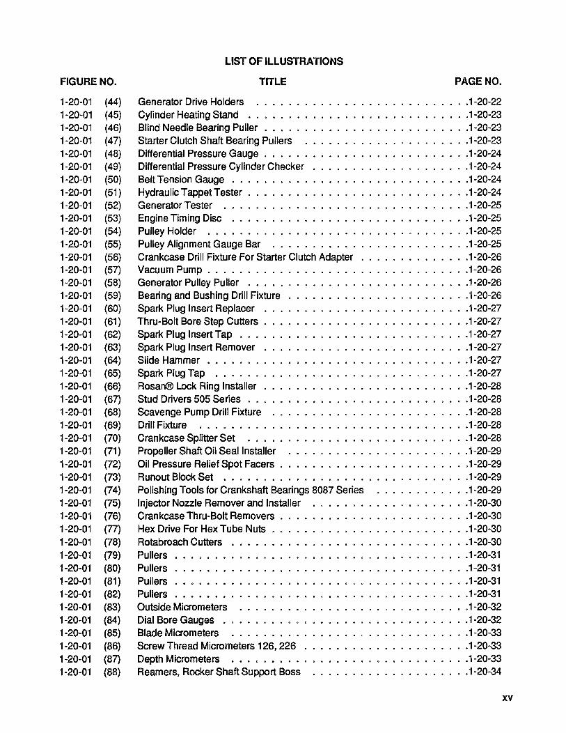
FIGURE NO.
1-20-01 (44) 1-20-01 (45) 1-20-01 (46) 1-20-01 (47) 1-20-01 (48) 1-20-01 (49) 1-20-01 (50) 1-20-01 (51 ) 1-20-01 (52) 1-20-01 (53) 1-20-01 (54) 1-20-01 (55) 1-20-01 (56) 1-20-01 (57) 1-20-01 (58) 1-20-01 (59) 1-20-01 (60) 1-20-01 (61) 1-20-01 (62) 1-20-01 (63) 1-20-01 (64) 1-20-01 (65) 1-20-01 (66) 1-20-01 (67) 1-20-01 (68) 1-20-01 (69) 1-20-01 (70) 1-20-01 (71) 1-20-01 (72) 1-20-01 (73) 1-20-01 (74) 1-20-01 (75) 1-20-01 (76) 1-20-01 (n) 1-20-01 (78) 1-20-01 (79) 1-20-01 (80) 1-20-01 (81 ) 1-20-01 (82) 1-20-01 (83) 1-20-01 (84) 1-20-01 (85) 1-20-01 (86) 1-20-01 (87) 1-20-01 (88)
LIST OF ILLUSTRATIONS
TITLE PAGE NO.
Generator Drive Holders .......................... .1-20-22 Cylinder Heating Stand ........................... .1-20-23 Blind Needle Bearing Puller . . . . . . . . . . . . . . . . . . . . . . . . . .1-20-23 Starter Clutch Shaft Bearing Pullers .................... .1-20-23 Differential Pressure Gauge . . . . . . . . . . . . . . . . . . . . . . . . . .1-20-24 Differential Pressure Cylinder Checker . . . . . . . . . . . . . . . . . . . .1-20-24 Belt Tension Gauge . . . . . . . . . . . . . . . . . . . . . . . . . . . . .. 1-20-24 Hydraulic Tappet Tester . . . . . . . . . . . . . . . . . . . . . . . . . . .. 1-20-24 Generator Tester ............................. .. 1-20-25 Engine Timing Disc ............................. .1-20-25 Pulley Holder ................................ .1-20-25 Pulley Alignment Gauge Bar ........................ .1-20-25 Crankcase Drill Fixture For Starter Clutch Adapter . . . . . . . . . . . . . .1-20-26 Vacuum Pump ................................. 1-20-26 Generator Pulley Puller ..... . . . . . . . . . . . . . . . . . . . . . .. 1-20-26 Bearing and Bushing Drill Fixture . . . . . . . . . . . . . . . . . . . . . . .1-20-26 Spark Plug Insert Replacer ......................... .1-20-27 Thru-Bolt Bore Step Cutters . . . . . . . . . . . . . . . . . . . . . . . . . .1-20-27 Spark Plug Insert Tap . . . . . . . . . . . . . . . . . . . . . . . . . . . . .1-20-27 Spark Plug Insert Remover ... . . . . . . . . . . . . . . . . . . . . . . .1-20-27 Slide Hammer . . . . . . . . . . . . . . . . . . . . . . . . . . . . . . . . .1-20-27 Spark Plug Tap ............................... .1-20-27 Rosan® Lock Ring Installer . . . . . . . . . . . . . . . . . . . . . . . . . .1-20-28 Stud Drivers 505 Series . . . . . . . . . . . . . . . . . . . . . . . . . . . .1-20-28 Scavenge Pump Drill Fixture ........................ .1-20-28 Drill Fixture ................................. .1-20-28 Crankcase Splitter Set ........................... .1-20-28 Propeller Shaft Oil Seal Installer ...................... .1-20-29 Oil Pressure Relief Spot Facers . . . . . . . . . . . . . . . . . . . . . . . .1-20-29 Runout Block Set .............................. .1-20-29 Polishing Tools for Crankshaft Bearings 8087 Series ........... .1-20-29 Injector Nozzle Remover and Installer ................... .1-20-30 Crankcase Thru-Bolt Removers . . . . . . . . . . . . . . . . . . . . . . . .1-20-30 Hex Drive For Hex Tube Nuts . . . . . . . . . . . . . . . . . . . . . . . . .1-20-30 Rotabroach Cutters ... . . . . . . . . . . . . . . . . . . . . . . . . . . .1-20-30 Pullers . . . . . . . . . . . . . . . . . . . . . . . . . . . . . . . . . . . . .1-20-31 Pullers . . . . . • . . . . . . . . . . . . . . . . . . . . . . . . . . . . . . .1-20-31 Pullers . • . . . . . . . . . . . . . . . . . . . . . . . . . . . . . . . . . . .1-20-31 Pullers . • . . . . . . . . . . . . . . . . . . . . . . . . . . . . . . . . . . .1-20-31 Outside Micrometers ............................ .1-20-32 Dial Bore Gauges . . . . . . . . . . . . . . . . . . . . . . . . . . . . . . .1-20-32 Blade Micrometers ............................. .1-20-33 Screw Thread Micrometers 126, 226 . . . . . . . . . . . . . . . . . . . . .1-20-33 Depth Micrometers .•........................... .1-20-33 Reamers, Rocker Shaft Support Boss ................... .1-20-34
xv

FIGURE NO.
1-20-01 (88) 1-20-01 (89) 1-20-01 (90) 1-20-01 (91 ) 1-20-01 (92) 1-20-01 (93) 1-20-01 (94) 1-20-01 (9S) 1-20-01 (96) 1-20-01 (97) 1-20-01 (98) 1-20-01 (99) 1-20-01 (100) 1-20-01 (101 ) 1-20-01 (102) 1-20-01 (103) 1-20-01 (104) 1-20-01 (10S) 1-20-01 (106) 70-10-00 70-20-00 70-S0-0'1 70-S0-02 70-S0-03 70-S0-04 72-00-03 72-00-09 72-00-10 72-00-11 72-00-14 72-10-0SA 72-10-0SB 72-10-06A 72-10-06B 72-10-06C 72-10-07 72-10-08A 72-10-08B 72-10-08C 72-10-09A 72-10-09B 72-10-10 72-10-11 72-10-12 72-10-13A
xvi
LIST OF ILLUSTRATIONS
TITLE
Reamers, Rocker Arm & Shaft Bushing . . . . . . . . . . . . . . . . Reamers Valve Guide Boss . . . . . . . . . . . . . . . . . . . Engine Application Chart for Valve Guide Stem Hole Reamers. Square Shank Reamers . . . . . . . Valve Guide Stem Hole Plug Gauges Dial Thickness Gauge ... . Precision Vernier Calipers ..... . Inside Measuring Instruments . . .. ...... . Alternator, Voltage Regulator Tester ....... . ...... . Alternator/Regulator/Battery Tester ....... " ....... . Multiple Voltage & Circuit Tester. . ............... . Magneto Timing Light . . . . . . . . . Timing Indicator . . . . ....... . Cold Cylinder Tester . . ....... . Hi-Voltage Tester .. . .... . Master Orifice Tool . .
PAGE NO.
1-20-34 1-20-34 1-20-3S 1-20-3S 1-20-3S 1-20-36 1-20-36 1-20-36 1-20-37 1-20-37 1-20-37 1-20-38 1-20-38 1-20-38 1-20-39 1-20-39
Alcor Portable Digital EGT Unit . . . . .......... . 1-20-39 1-20-40 1-20-40
Alcor Portable Digital CHT Unit . . . . . . . . . . . . . . . Federal Dimensionair Gage . . . . . . . . . . . . . . . . Lockwire Procedure . . . . . . . . . . . . . . . . . . . . .. . . . . Crankcase Sealant and Threading Procedure ............ . Master Orifice Tool . . . . . . . . . . . . . . . . . . . . . . . Static & Dynamic Seal . . . . . . . . . . . . . . . . . . Differential Pressure Tester . . . . . . . ....... . Dynamic Seal Check. . . . . . . . . . . . . . . . . . . . . . . . . Crankshaft Numbering . . . . . ........... . Gear Train Diagram . . . . . . . . . . . . . . . . . . . . . . . . . . . . Lubrication System. . . . . . . . . . . . . . . . . . . . . . . . . . . . . Barrel Type Hydraulic Lifter . .. . ............... . Ignition System Wiring Diagram. ............... . . Ignition System (IO-SSO-D,E & L) ............ . Ignition System (IO-SSO-F) . . . . ..... . . . . . . . . . . . . Fuel Injection System (IO-SSO-D) ................ . Fuel Injection System (IO-SSO-E) . . . . . . . . . . . . . . . . . Fuel Injection System (IO-SSO-F & L) . . . . . . . . . . . . . . . . . Magneto & Accessory Drives .................... . Induction System (IO-SSO-D) .................... . Induction System (IO-SSO-E). . . . . . . . . . . . . . . . . . . . . . Induction System (IO-SSO-F & L) .................. . Oil Sump (IO-SSO-D,E & F) ..................... . Oil Sump (IO-SSO-L) . . . . . .. . ............... . Oil Cooler ............ . ............... . Alternator Assembly . . . . . . . Starter and Starter Drive Adapter Oil Pump Assembly (IO-SSO-D & F) ..
70-10-01 70-20-01 70-S0-01 70-S0-02 70-S0-03 70-S0-0S 72-00-07 72-00-10 72-00-12 72-00-13 72-00-1S 72-10-0S 72-10-07 72-10-09 72-10-11 72-10-13 72-10-14 72-10-1S 72-10-17 72-10-19 72-10-20 72-10-21 72-10-23 72-10-2S 72-10-27 72-10-29
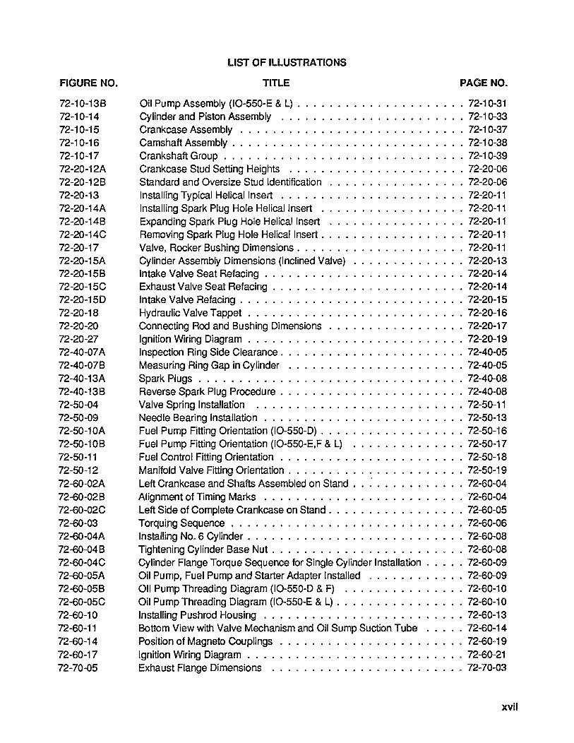
FIGURE NO.
72-10-138 72-10-14 72-10-15 72-10-16 72-10-17 72-20-12A 72-20-128 72-20-13 72-20-14A 72-20-148 72-20-14C 72-20-17 72-20-15A 72-20-158 72-20-15C 72-20-15D 72-20-18 72-20-20 72-20-27 72-40-07A 72-40-078 72-40-13A 72-40-138 72-50-04 72-50-09 72-50-10A 72-50-108 72-50-11 72-50-12 72-60-02A 72-60-028 72-60-02C 72-60-03 72-60-04A 72-60-048 72-60-04C 72-60-05A 72-60-058 72-60-05C 72-60-10 72-60-11 72-60-14 72-60-17 72-70-05
LIST OF ILLUSTRATIONS
TITLE PAGE NO.
Oil Pump Assembly (10-550-E & L) .............•....... 72-10-31 Cylinder and Piston Assembly ....................... 72-1 0-33 Crankcase Assembly ............................ 72-10-37 Camshaft Assembly ............................. 72-10-38 Crankshaft Group . . . . . . . . . . . . . . . . . . . . . . . . . . . . . . 72-10-39 Crankcase Stud Setting Heights ...................... 72-20-06 Standard and Oversize Stud Identification . . . . . . . . . . . . . . . . . 72-20-06 Installing Typical Helical Insert ....................... 72-20-11 Installing Spark Plug Hole Helical Insert .................. 72-20-11 Expanding Spark Plug Hole Helical Insert ...........•....• 72-20-11 Removing Spark Plug Hole Helical Insert ...............•.. 72-20-11 Valve, Rocker 8ushing Dimensions. . . . . . . . . . . . . . . . . . . . . 72-20-11 Cylinder Assembly Dimensions (Inclined Valve) .............. 72-20-13 Intake Valve Seat Refacing ......................... 72-20-14 Exhaust Valve Seat Refacing ........................ 72-20-14 Intake Valve Refacing ............................ 72-20-15 Hydraulic Valve Tappet ........................... 72-20-16 Connecting Rod and 8ushing Dimensions ...............•. 72-20-17 Ignition Wiring Diagram ........................... 72-20-19 Inspection Ring Side Clearance. . . . . . . . . . . . . . . . • . . . . . . 72-40-05 Measuring Ring Gap in Cylinder . . . . . . . . . . . . . . . . • . . . . . 72-40-05 Spark Plugs ................................. 72-40-08 Reverse Spark Plug Procedu re . . . . . . . . . . . . . . . . . . . . . . . 72-40-08 Valve Spring Installation ....................•...•. 72-50-11 Needle 8earing Installation ......••....•..•......... 72-50-13 Fuel Pump Fitting Orientation (10-550-D) . • • • . . . . . . . . . . . . . . 72-50-16 Fuel Pump Fitting Orientation (10-550-E,F & L) ..•........... 72-50-17 Fuel Control Fitting Orientation . . . . . . . . . . . . . . . . • . . . . • . 72-50-18 Manifold Valve Fitting Orientation ....•.....•..•........ 72-50-19 Left Crankcase and Shafts Assembled on Stand . . : . . . . • • . . . . . 72-60-04 Alignment of Timing Marks . . . . . . . . . . . . . . . . . . . . . . . . . 72-60-04 Left Side of Complete Crankcase on Stand. . . . . . . . . . . . . . . . . 72-60-05 Torquing Sequence ............................. 72-60-06 Installing No.6 Cylinder . . . . . . . . • . . . . . . . . . . . . . . . . . . 72-60-08 Tightening Cylinder Base Nut . . . . . . . . . . . . . . . . . . . • . . . . 72-60-08 Cylinder Flange Torque Sequence for Single Cylinder Installation ...•. 72-60-09 Oil Pump, Fuel Pump and Starter Adapter Installed .....••..... 72-60-09 011 Pump Threading Diagram (10-550-D & F) ..........•..•. 72-60-10 Oil Pump Threading Diagram (10-550-E & L) .•.............. 72-60-10 Installing Pushrod Housing . . . . . . . . . . . . . . . . . • . . • . . . . 72-60-13 80ttom View with Valve Mechanism and Oil Sump Suction Tube ..... 72-60-14 Position of Magneto Couplings . . . . . • . • . • . • • . . • • . • • • . • 72-60-19 Ignition Wiring Diagram . • . . . • . . . . . . . . . . . . . • • . . . • • . 72-60-21 Exhaust Flange Dimensions ................•••..... 72-70-03
xvii
FIGURE NO.
73-00-00 74-10-02A 74-10-02B
xviii
LIST OF ILLUSTRATIONS
TITLE PAGE NO.
Fuel System Schematic .......................... 73-00-03 Coating Insulating Sleeve ...•.•..••............... 74-10-01 Installation of Elbow Clamp ........................ 74-10-01
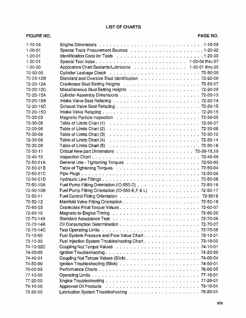
FIGURE NO.
1-10-04 1-20-01 1-20-01 1-20-01 1-30-00 70-50-05 72-20-12B 72-20-12A 72-20-12C 72-20-15A 72-20-15B 72-20-15C 72-20-15D 72-30-03 72-30-08 72-30-08 72-30-08 72-30-08 72-30~08 72-30-11 72-40-15 72-50-01A 72-50-01 B 72-50-01C 72-50-01 D 72-50-10A 72-50-10B 72-50-11 72-50-12 72-60-03 72-60-15 72-70-14A 72-70-14B 72-70-14C 73-10-02 73-10-03 74-10-02C 74-20-00 74-40-01 74-50-00 76-00-03 77-10-00 77-20-00 79-10-00 79-20-00
LIST OF CHARTS
Engine Dimensions . . . . . . . . . Special Tools Procurement Sources Identification Code for Tools ... . Special Tool Index ......... . Application Chart Sealants/Lubricants .... Cylinder Leakage Check .... . . . . . Standard and Oversize Stud Identification Crankcase Stud Setting Heights .. Miscellaneous Stud Setting Heights Cylinder Assembly Dimensions . Intake Valve Seat Refacing .. Exhaust Valve Seat Refacing . . Intake Valve Refacing . . . . . Magnetic Particle Inspection ... . Table of Limits Chart (1) ..... . Table of Limits Chart (2) Table of Limits Chart (3) Table of Limits Chart (4) Table of Limits Chart (5) Critical New part Dimensions . . Inspection Chart. . . . . . . . . General Use - Tightening Torques . . . . . . Table of Tightening Torques ........ . Pipe Plugs ................ . Hydraulic Line Fittings . . . . . . . . . . . . . Fuel Pump Fitting Orientation (10-550-D) . . . Fuel Pump Fitting Orientation (10-550-E,F & L) . Fuel Control Fitting Orientation . . . Manifold Valve Fitting Orientation .. Crankcase Final Torque Values. . . Magneto-to-Engine Timing . . . . . Standard Acceptance Test . . . . . . Oil Consumption Determination . . . . Test Operating Limits ........ . Fuel System Pressure and Flow Value Chart. Fuel Injection System Troubleshooting Chart. Coupling Nut Torque Values ........ . Ignition Troubleshooting. . . . . . . . . . . . Coupling Nut Torque Values (Slick) . . . . Ignition Troubleshooting (Slick) . . . . . . Performance Charts. . . . . . . . . . . . Operating Limits . . . . . . . . . . . . . Engine Troubleshooting . . . . . . . Approved Oil Products ...... . Lubrication System Troubleshooting
PAGE NO.
· .1-10-09 ..... 1-20-02 ..... 1-20-03 1-20-04 thru 07 1-30-01 thru 05
· 70-50-06 · 72-20-06 · 72-20-07 · 72-20-08 · 72-20-13 · 72-20-14 · 72-20-15 · 72-20-15 · 72-30-05 · 72-30-07 · 72-30-08 · 72-30-12 · 72-30-14 · 72-30-16
. 72-30-18,19 · 72-40-09 · 72-50-03 · 72-50-04 · 72-50-08 · 72-50-08 · 72-50-16 · 72-50-17 · 72-5018 · 72-50-19 · 72-60-07 · 72-60-20 · 72-70-06 · 72-70-07 · 72-70-08 · 73-10-01 · 73-10-02 · 74-10-01 · 74-20-00 · 74-00-04 · 74-50-01 · 76-00-05 · 77-10-01 · 77-20-01 · 79-10-01
79-20-01
xix

xx
INTENTIONALLY
LEFT
BLANK
1-00-00 .
1-00-01
1-00-02
1-00-03
1-00-04
1-10-00 1-10-01
1-10-02
1-10-03
1-10-04
1-20-00 1-20-01
1-30-00 1-30-01
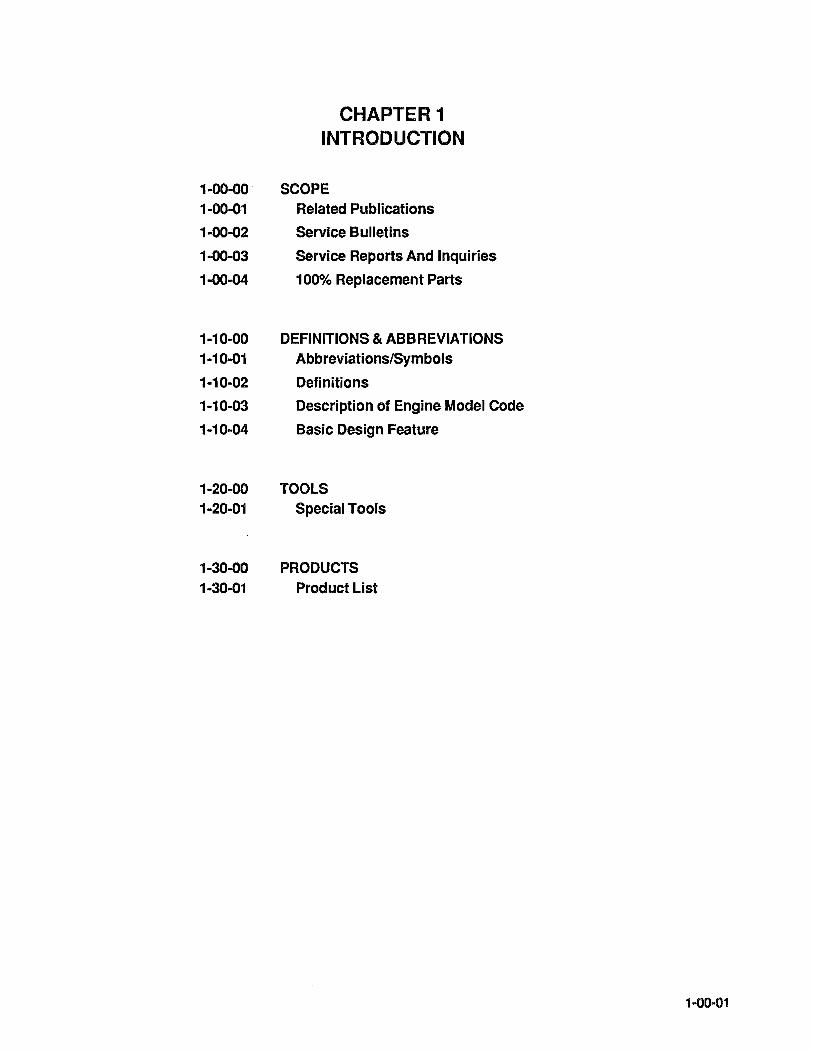
CHAPTER 1 INTRODUCTION
SCOPE Related Publications
Service Bulletins
Service Reports And Inquiries
100% Replacement Parts
DEFINITIONS & ABBREVIATIONS Abbreviations/Symbols
Definitions
Description of Engine Model Code
Basic Design Feature
TOOLS Special Tools
PRODUCTS Product List
1-00-01

1-00-02
INTENTIONALLY
LEFT
BLANK

1-00-00
1-00-01
SCOPE
Recommendations, cautions and warnings regarding overhaul of this engine are not intended to impose undue restrictions, they are inserted to obtain maximum performance from the engine in accordance with safety and efficiency. Abuse, misuse, or neglect of any piece of equipment can cause eventual failure. For an aircraft engine, it is obvious that a failure may have disastrous consequences. Failure to observe the instructions contained in this manual constitutes unauthorized operation in areas unexplored during development of the engine, or in areas which experience has proved to be undesirable or detrimental.
NOTES, Cautions and Warnings are included throughout this manual. Application is as follows:
NOTE ... Special interest information which may facilitate the operation of equipment.
Caution .. . Information issued to emphasize certain instructions or to prevent possible damage to engine or accessories.
Warning .. .lnformation which, if disregarded, may result in severe damage to or destruction of the engine or endangerment to personnel.
RELATED PUBLICATIONS
A. Engine Manuals
1. Maintenance and Overhaul for 10-550 Sandcast Series Aircraft Engine, Form X30605.
2. Illustrated Parts Catalog for 10-550 Sandcast Series Aircraft Engine, Form X30606A.
3. Teledyne Continental Motors Aircraft Engine Service Bulletins.
4. Fuel Injection Manual. Form X30593A.
5. Starter Service instructions Form, X30592
The above publications can be ordered through your Teledyne Continental Motors Distributor or ordered directly, if prepaid, from:
Teledyne Continental Motors Aircraft Products P. O. Box 90 Mobile, AL 36601 Attn: Accounts Receivable
1-00-03

1-00-02
1-00-03
1-00-04
B. Accessory Manuals:
1. Magnetos Service Manual Form X40000 Teledyne Continental Motors Aircraft Products P.O. Box 90 Mobile, AL 36601 Attn: Publications Department
Service Manual Slick Electro Inc. 530 Blackhawk Park Avenue Rockford, Illinois 61100
2. Alternator Alternator Service Instructions Form X30531-3 Teledyne Continental Motors Aircraft Products P.O. Box 90 Mobile, AL 36601 Attn: Publications Department
3. Starter Starter Service Instructions Form X30592 Teledyne Continental Motors Aircraft Products P.O. Box 90 Mobile, AL 36601 Attn: Publications Department
BULLETINS. Bulletins that are issued to Distributors and subscribers from Teledyne Continental Motors are divided into three separate groups: (1) Customer Information Bulletins; (2) Service Bulletins and (3) Mandatory Service Bulletins.
(1) Customer Information Bulletins are published to help provide the latest information on TCM marketing procedures, policies and product information.
(2) Service Bulletins provide current information related to service, maintenance and technical support of the product.
(3) Mandatory Service Bulletins are issued with required compliance information that may affect safety of flight.
These bulletins are also available to owners, operations or maintenance personnel on an annual subscription basis.
SERVICE REPORTS AND INQUIRIES. If for any reason you have an inquiry or require technical assistance beyond the scope of your service facility, contact your local TCM distributor or TCM field representative. Requests for copies of Teledyne Continental Aircraft Engine Service publications should be made through your distributor or Teledyne Continental Motors, Aircraft Products P.O. Box 90, Mobile, AL 36601, Attn: Publications Dept.
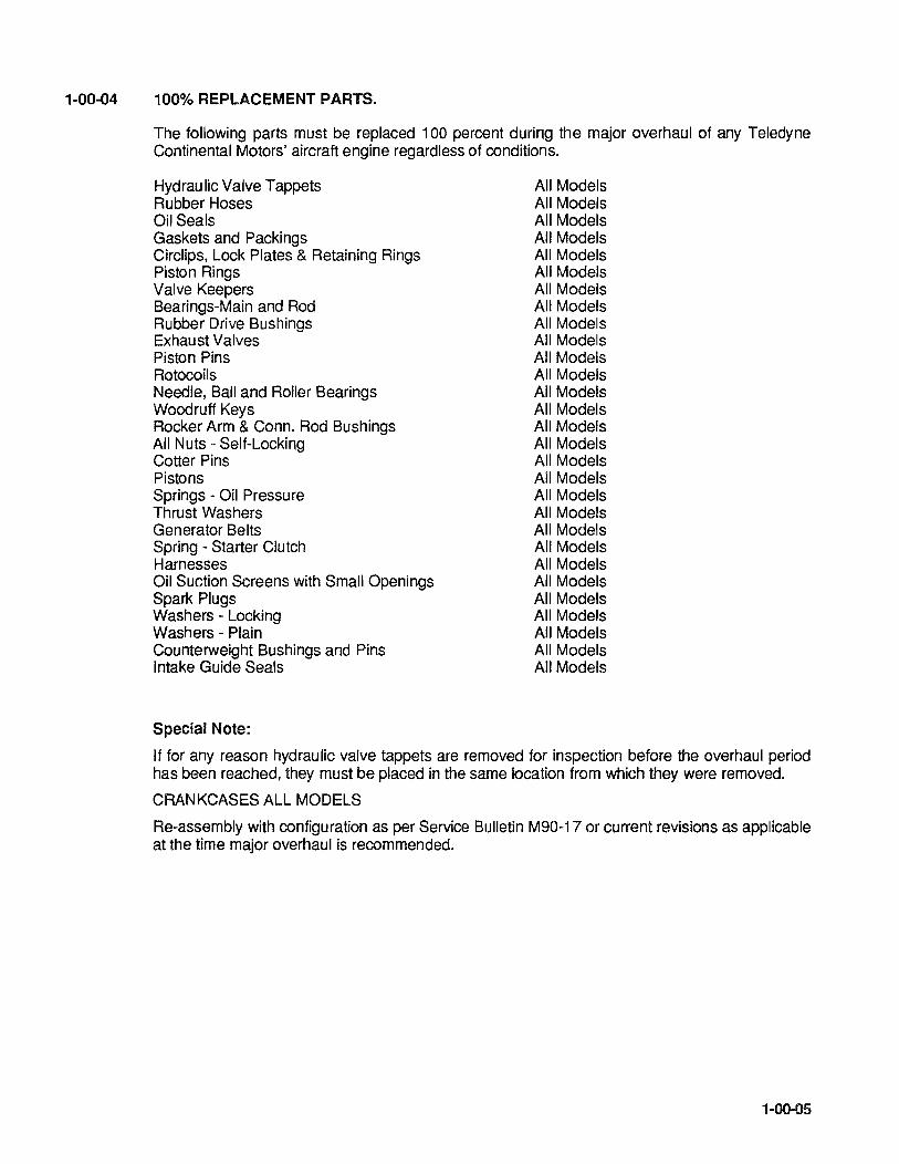
1-00-04 100% REPLACEMENT PARTS.
The following parts must be replaced 100 percent during the major overhaul of any Teledyne Continental Motors' aircraft engine regardless of conditions.
HydrauliC Valve Tappets Rubber Hoses Oil Seals Gaskets and Packings Circlips, Lock Plates & Retaining Rings Piston Rings Valve Keepers Bearings-Main and Rod Rubber Drive Bushings Exhaust Valves Piston Pins Rotocoils Needle, Ball and Roller Bearings Woodruff Keys Rocker Arm & Conn. Rod Bushings All Nuts - Self-Locking Cotter Pins Pistons Springs - Oil Pressure Thrust Washers Generator Belts Spring - Starter Clutch Harnesses Oil Suction Screens with Small Openings Spark Plugs Washers - Locking Washers - Plain Counterweight Bushings and Pins Intake Guide Seals
Special Note:
All Models All Models All Models All Models All Models All Models All Models All Models All Models All Models All Models All Models All Models All Models All Models All Models All Models All Models All Models All Models All Models All Models All Models All Models All Models All Models All Models All Models All Models
If for any reason hydraulic valve tappets are removed for inspection before the overhaul period has been reached, they must be placed in the same location from which they were removed.
CRANKCASES ALL MODELS
Re-assembly with configuration as per Service Bulletin M90-17 or current revisions as applicable at the time major overhaul is recommended.
1-00-05

1-00-06
INTENTIONALL Y
LEFT
BLANK

1-10-00
1-10-01
DEFINITIONS AND ABBREVIATIONS
ABBREVIATIONS/SYMBOLS
TERM
A.B.C. ADMP Approx. A.T.C. Bar. B.B.C. B.H.P. BSFC B.T.C. FAA C.A.R. C.G. c.f.m. C.H.T. CCW CW
of EGT Fig. Front ft. F.T. FT-LBS G.P.M. gms Hex H20 Hg. hr. 1.0. IN-LBS in. (") Left Side
Lbs. Lockwire 100LL Man. Max. Min. 30' N.P.T. N.C. N.F. NRP OAT 0.0. oz.
EXPLANATION
After Bottom Center Absolute Dry Manifold Pressure Approximately After Top Center Barometric Before Bottom Center Brake Horsepower Brake Specific Fuel Consumption Before Top Center Federal Aviation Administration Civil Air Regulations Center of Gravity Cubic Feet Per Minute Cylinder Head Temperature Counterclockwise Rotation Clockwise Rotation Degrees of Angle Degrees Fahrenheit Exhaust Gas Temperature Figure (Illustration) Propeller End of Engine Foot or Feet Full Throttle Foot Pounds Torque Gallons Per Minute Grams Hexagon Water Mercury Hour Inside Diameter Inch Pounds Torque Inches Side on which No's 2,4 and 6 cylinders are located. (Rear to Front) Pounds Stainless steel wire used to safety connections, etc. 100 Octane Low Lead Fuel Manifold Manometer Maximum Minimum Thirty minutes of angle (60' equal one degree) National Pipe Thread (Tapered) National Course (Thread) National Fine (Thread) Normal Rated Power Outside Air Temperature Outside Diameter Ounce
1-10-01
1-10-02
ADMP
Ambient
BHP
BSFC
Cavitation
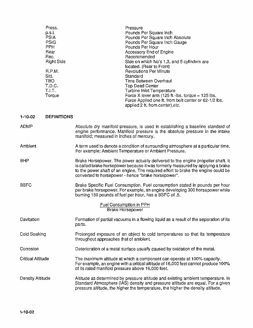
Press. p.s.i. PSIA PSIG PPH Rear Rec. Right Side
R.P.M. Std. TBO T.D.C. T.I.T. Torque
DEFINITIONS
Cold Soaking
Corrosion
Critical Altitude
Density Altitude
1-10-02
Pressure Pounds Per Square Inch Pounds Per Square Inch Absolute Pounds Per Square Inch Gauge Pounds Per Hour Accessory End of Engine Recommended Side on which No's 1,3, and. 5 cylinders are located. (Rear to Front) Revolutions Per Minute Standard Time Between Overhaul Top Dead Center Turbine Inlet Temperature Force X lever arm (125 ft.-Ibs. torque = 125 Ibs. Force Applied one ft. from bolt center or 62-1/2 Ibs. applied 2 ft. from center),etc.
Absolute dry manifold pressure, is used in establishing a baseline standard of engine performance. Manifold pressure is the absolute pressure in the intake manifold; measured in inches of mercury.
A term used to denote a condition of surrounding atmosphere at a particular time. For example; Ambient Temperature or Ambient Pressure.
Brake Horsepower. The power actually delivered to the engine propeller shaft. It is called brake horsepower because it was formerly measured by applying a brake to the power shaft of an engine. The required effort to brake the engine could be converted to horsepower - hence "brake horsepower".
Brake Specific Fuel Consumption. Fuel consumption stated in pounds per hour per brake horsepower. For example, an engine developing 300 horsepower while burning 150 pounds of fuel per hour, has a BSFC of .5.
Fuel Consumption in PPH Brake Horsepower
Formation of partial vacuums in a flowing liquid as a result of the separation of its parts.
Prolonged exposure of an object to cold temperatures so that its temperature throughout approaches that of ambient.
Deterioration of a metal surface usually caused by oxidation of the metal.
The maximum altitude at which a component can operate at 100% capacity. For example, an engine with a critical altitude of 16,000 feet cannot produce 100% of its rated manifold pressure above 16,000 feet.
Altitude as determined by pressure altitude and existing ambient temperature. In Standard Atmosphere (lAS) density and pressure altitude are equal. For a given pressure altitude, the higher the temperature, the higher the density altitude.
Dynamic Condition
E.G.T.
Exhaust Back Pressure
Four Cycle
Fuel Injection
Gallery
Galling or Scuffing
Humidity
Hydrostatic Lock
Impulse Coupling
Lean Limit Mixture.
Major Overhaul
Manifold Pressure
Mixture
Naturally Aspirated (Engine)
Octane Number
A term referring to properties of a body in motion.
Exhaust Gas Temperature. Measurement of this gas temperature is sometimes used an aid to fuel management.
Opposition to the flow of exhaust gas, primarily caused by the size and shape of the exhaust system. Atmospheric pressure also affects back pressure.
Short for "Four Stroke Cycle." It refers to the four strokes of the piston in completing a cycle of engine operation (Intake, Compression, Power and Exhaust).
A process of metering fuel into an engine by means other than a carburetor.
A passageway in the engine or subcomponent. Generally one through which oil is flowed.
Excessive friction between two metal surfaces resulting in particles of the softer metal being torn away and literally welded to the harder metal
Moisture in the atmosphere. Relative humidity, expressed in percent, is the amount of moisture (water vapor) in the air compared with the maximum amount of moisture the air could contain at a given temperature.
Inability or restriction of piston rotation at TDC due to fluid accumulation in excess of combustion chamber displacement.
A mechanical device used in some magnetos to retard the ignition timing and provide higher voltage at cranking speeds for starting.
The leanest mixture approved for any given power condition. It is not necessarily the leanest mixture at which the engine will continue to operate.
Per FAA AC43-11 consists of the complete disassembly of an engine, inspected, repaired as necessary, reassembled, tested and approved for return to service within the fits and limits specified by the manufacturer's overhaul data. This should be to new fits or limits. The determination as to what fits and limits are used during an engine overhaul should be clearly understood by the engine owner at the time the engine is presented for overhaul. The owner should also be aware of any parts that are replaced, regardless of condition, as a result of manufacturer's overhaul data, service bulletin, or an airworthiness directive.
Pressure as measured in the Intake manifold down-stream of the air throttle. Usually measure in inches of mercury.
Mixture ratio. The proportion of fuel to air used for combustion.
A term used to describe an engine which obtains induction air by drawing it directly from the atmosphere into the cylinder. A non-supercharged engine.
A rating which describes relative anti-knock (detonation) characteristics of fuel. Fuels with greater detonation resistance than 100 octane are given performance ratings.
1-10-03

Oil Temperature Control A thermostatic valve used to divert oil through or around the oil cooler, as Valve necessary, to maintain oil temperature within desired limits (ref. vernatherm valve).
Overboost Valve A pressure relief valve, set slightly in excess of maximum deck pressure, to prevent damaging overboost in the event of a system malfunction.
Overhead Valves An engine configuration in which the valves are located in the cylinder head itself.
Performance Rating A rating system used to describe the ability of fuel to withstand heat and pressure of combustion as compared with 100 octane fuel. For example, an engine with high compression and high temperature needs a higher Performance Rated fuel than a low compression engine. A rating of 100/130 denotes performance characteristics of lean (100) and rich (130) mixtures respectively.
Permold A term used to describe a process by which a crankcase is made. An engine with a permold crankcase has a front, right-handed mounted, gear driven alternator.
Pressure Altitude Altitude, usually expressed in feet, (using absolute static pressure as a reference) equivalent to altitude above the standard sea level reference plan (29.92" Hg. Standard).
Propeller Load Curve A plot of horsepower, versus RPM, depicting the power absorption characteristics of a fixed pitch propeller.
Propeller Pitch The angle between the mean chord of the propeller and the plane of rotation.
PSIA The absolute thermodynamic pressure measured by the number of pounds-force exerted on an area of one square inch.
Ram Increased air pressure due to forward speed.
Rated Power The maximum horsepower at which an engine is approved for operation.
Retarded Breaker A device used in magnetos to delay ignition during cranking. It is used to facilitate starting.
Rich Limit The richest fuel/air ratio permitted for a given power condition. It is not necessarily the richest condition at which the engine will run.
Rocker Arm A mechanical device used to transfer motion from the pushrod to the valve.
Run Out Eccentricity or wobble of a rotating part.
Sandcast A term used to describe a process by which a crankcase is made. An engine with a sandcast crankcase has belt driven alternator mounted on the left rear accessory case and a front, right-hand mounted oil cooler.
Scavenge Pump A Pump (especially an oil pump) to prevent accumulation of liquid in some particular area.
Sonic Venturi A restriction, especially in cabin pressurization systems, to limit the flow of air through a duct.
Standard Day By general acceptance, a condition of the atmosphere wherein specific amounts of temperature, pressure, humidity, etc. exist.
1-10-04

Static Condition
Sump
T.O.C.
Thermal Efficiency
T.I.T.
Torque
Turbocharger
Turbo Supercharged (engine)
Vapor Lock
Variable Pressure Controller
Vernatherm Valve
Viscosity
Volatility
Volumetric Efficiency
A term referring to properties of a body at rest.
The lowest part of a system. The main oil sump on a wet sump engine contains the oil supply.
Top Dead Center. The position in which the piston has reached the top of its travel. A line drawn between the crankshaft rotational axis, through the connecting rod end axis and the piston pin center would be straight line. Ignition and valve timing are stated in terms of degrees before or after TOC.
Regarding engines, the percent of total heat generated which is converted into useful power.
Turbine Inlet Temperature. The measurement of E.G.T. at the turbo- charger turbine inlet.
Twisting moment, or leverage. stated in pounds - foot (or pounds-inch).
A device used to supply increased amounts of air to an engine induction system. In operation, a turbine is driven by engine exhaust gas. In turn, the turbine directly drives a compressor which pumps air into the engine intake.
A term used to describe an engine which obtains induction air by drawing it directly from the atmosphere into the Turbocharger Compression Inlet, compressing the air and routing it to the pressurized induction system.
A condition in which the proper flow of a liquid through a system is disturbed by the formation of vapor. Any liquid will turn to vapor if heated sufficiently. The amount of heat required for vaporization will depend on the pressure exerted on the liquid.
A device used to control the speed, and thus the output of the turbocharger. It does so by operating the wastegate which diverts, more or less, exhaust gas over the turbine.
A thermostatic valve used to divert oil through or around the oil cooler, as necessary, to maintain oil temperature within desired limits.
The characteristic of a liquid to resist flowing. Regarding oil, high viscosity refers to thicker or "heavier" oil while low viscosity oil is thinner. Relative viscosity is indicated by the specified "weight" of the oil such as 30 "weight" or 50 "weight". Some oils are specified as mUltiple-viscosity such as 10W30. In such cases, this oil is more stable and resists the tendency to thin when heated or thicken when it becomes cold.
The tendency of a liquid to vaporize.
The ability of an engine to fill its cylinders with air compared to their capacity for air under static conditions. A "naturally aspirated" engine will always have a volumetric efficiency of slightly less than 100%, whereas superchargers permit volumetric efficiencies in excess of 100%.
1-10-05

Wastegate Valve
DEFINITION OF TERMS
A unit, used on turbocharged engines, to divert exhaust gas through or around the turbine, as necessary to maintain turbine speed. As more air is demanded by the engine, due to throttle operation, the compressor must work harder. In order to maintain compressor and turbine speeds, more exhaust must be flowed through the turbine. The wastegate is usually operated by an actuator which gets necessary Signals from the turbocharger controller.
Front, rear, left and right, as used in this manual, refer to the engine as viewed by the mechanic in a normal position, facing the accessory end. Accessory end being the rear and propeller flange being the front of the engine. Cylinders are numbered starting from the rear, with odd numbers on the right and even numbers on the left.
1-10-03 DESCRIPTION OF ENGINE MODEL CODE
DETAILED ENGINE DESCRIPTION
Example:
10 - 550 Dill
Prefix _____________ ----ll IL-______ Specification Number
1- Fuel Injection
0- Horizontally Opposed Cylinder Configuration
Displace me nt
550 Cubic Inch Cylinder Volume Displacement
1-10-06
Refer to specification Manual X30508 for information.
'------ Suffix
The D Letter Identifies The Model of Engine
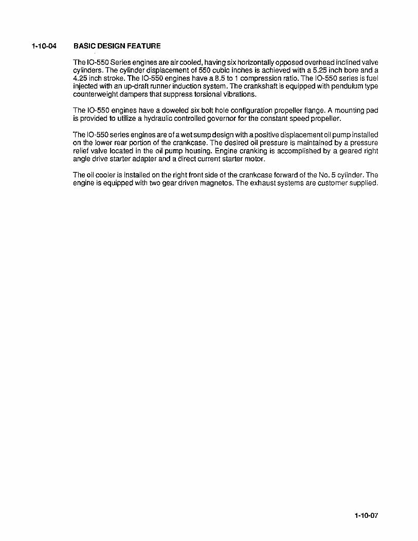
1-10-04 BASIC DESIGN FEATURE
The 10-550 Series engines are air cooled, having six horizontally opposed overhead inclined valve cylinders. The cylinder displacement of 550 cubic inches is achieved with a 5.25 inch bore and a 4.25 inch stroke. The 10-550 engines have a 8.5 to 1 compression ratio. The 10-550 series is fuel injected with an up-draft runner induction system. The crankshaft is equipped with pendulum type counterweight dampers that suppress torsional vibrations.
The 10-550 engines have a doweled six bolt hole configuration propeller flange. A mounting pad is provided to utilize a hydraulic controlled governor for the constant speed propeller.
The 10-550 series engines are of a wet sump design with a positive displacement oil pump installed on the lower rear portion of the crankcase. The desired oil pressure is maintained by a pressure relief valve located in the oil pump housing. Engine cranking is accomplished by a geared right angle drive starter adapter and a direct current starter motor.
The oil cooler is installed on the right front side of the crankcase forward of the No.5 cylinder. The engine is equipped with two gear driven magnetos. The exhaust systems are customer supplied.
1-10-07
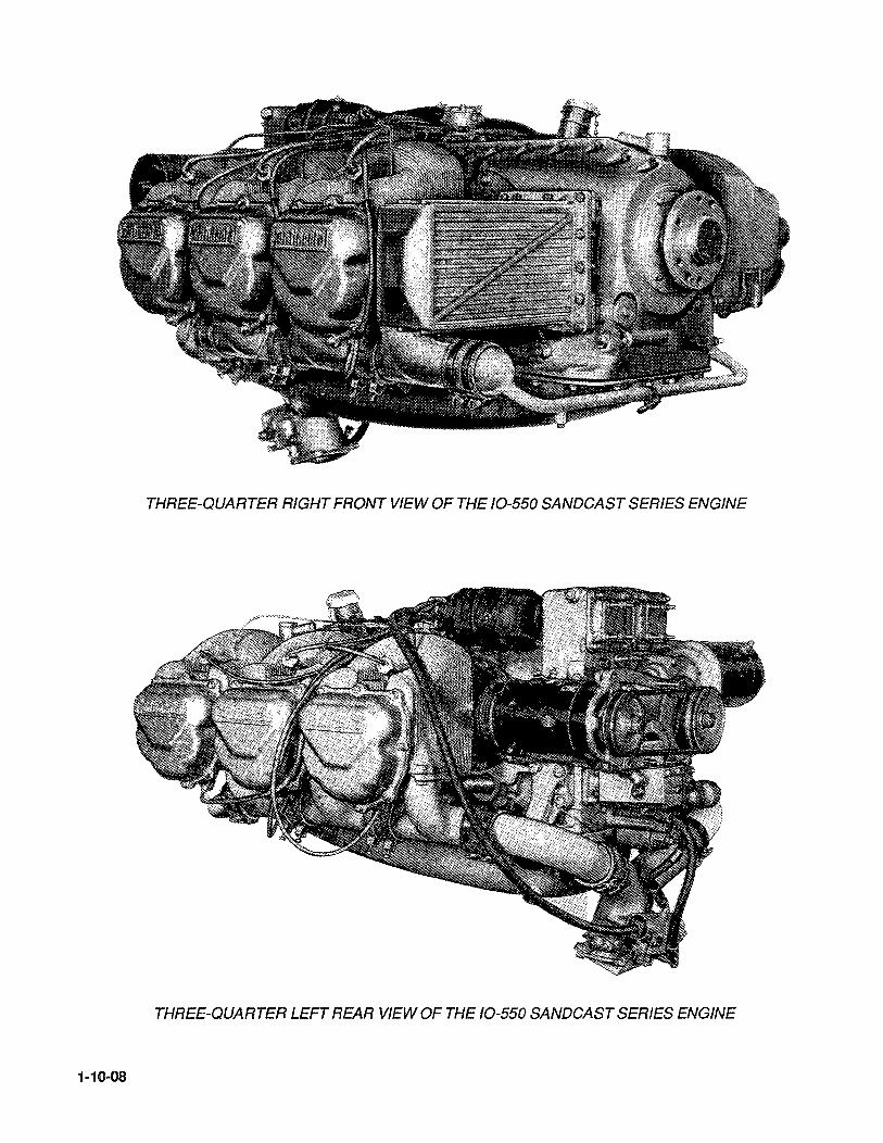
THREE-QUARTER RIGHT FRONT VIEW OF THE 10-550 SANDCAST SERIES ENGINE
THREE-QUARTER LEFT REAR VIEW OF THE 10-550 SANDCAST SERIES ENGINE
1-10-08

14--------A--------+l ~----------B----------~
c
t----D---~
INSTALLATION DRAWING 10-550
DIMENSIONS
MODEL
A B C D E F
10-5500 36.74 33.56 23.79 17.10 8.20 7.62
10-550E 43.91 33.56 19.75 17.10 8.20 7.62
10-550F 40.91 33.56 19.75 17.10 8.20 7.62
10-550L 40.91 33.56 23.25 17.10 8.20 7.62
1·10-09

1-10-10
INTENTIONALLY
LEFT
BLANK
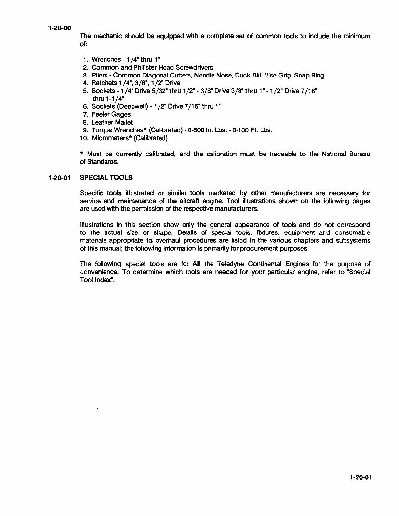
1-20-00 The mechanic should be equipped with a complete set of common tools to include the minimum of:
1. Wrenches -1/4" thru 1" 2. Common and Philister Head Screwdrivers 3. Pliers - Common Diagonal Cutters, Needle Nose, Duck Bill, Vise Grip, Snap Ring. 4. Ratchets 1/4", 3/S", 1/2" Drive 5. Sockets - 1 /4" Drive 5/32" thru 1 /2" - 3/S" Drive 3/S" thru 1" - 1 /2" Drive 7/ is"
thru 1-1/4" S. Sockets (Deepwell) - 1 /2" Drive 7/ is" thru 1" 7. Feeler Gages S. Leather Mallet 9. Torque Wrenches* (Calibrated) - 0-500 In. Lbs. - 0-100 Ft. Lbs.
10. Micrometers* (Calibrated)
* Must be currently calibrated, and the calibration must be traceable to the National Bureau of Standards.
1-20-01 SPECIAL TOOLS
Specific tools Ulustrated or similar tools marketed by other manufacturers are necessary for service and maintenance of the aircraft engine. Tool illustrations shown on the following pages are used with the permission of the respective manufacturers.
Illustrations in this section show only the general appearance of tools and do not correspond to the actual size or shape. Details of special tools, fixtures, equipment and consumable materials appropriate to overhaul procedures are listed in the various chapters and SUbsystems of this manual; the following Information is primarily for procurement purposes.
The following special tools are for All the Teledyne Continental Engines for the purpose of convenience. To determine which tools are needed for your particular engine, refer to ·Special Tool Index".
1-20-01

COMPANY
ALCOR
Box 32516 10130 Jones Maltsberger Rd. San Antonio, TX 78284 51 21349-3771
SPECIAL TOOLS Procurement Sources
BORROUGHS TOOL AND EQUIP. CORP. 2429 N. Burdick St. Kalamazoo, MI 49007-1897 616/345-5163 or 345-2700
CHAMPION SPARK PLUG, CO. Box 91 0,900 Upton Ave. Toledo, OH 43661 419/535-2461
EASTERN ELECTRONICS, INC. 180 Roberts St. East Hartford, CT 06108 203/528-9821
FEDERAL TOOL SUPPLY CO., INC. 1144 Eddy St. Providence, Rhode Island 02940 800/343-2050 TOLL FREE
OTC TOOLS & EQUIPMENT
Division of Owatonna Tool Company Owatonna, Minnesota 55060 507/451-5310
McMASTER-CARR SUPPLY CO.
P.O. Box 4355 Chicago, Illinois 60680 3121833-0300
SNAP ON TOOLS 2611 Commerce Blvd. Birmingham, Alabama 3521 0 205/956-1722
Kell-Strom Tool Company, Inc. 21 4 Church St. Wethersfield, CT 06109
1-20-02
GENERAL PRODUCT SUMMARY
Instruments for Light Powered Aircraft Special Tools
Precision Instruments Measuring Instruments Precision Tools Special Tools
Spark Plugs, Ignitors Oil Filters Special Tools
Fuel Pressure Test Equipment Measuring Instruments Precision Tools Piston Position Indicators Printed and Standard Circuits
Precision Inspection Instruments Special Tools
Precision Tools Special Tools Hydraulic Accessories
Precision Tools Special Tools
Precision Tools Special Tools
Ignition Test Equipment

- NOTICE-
All tools referenced under Sub-section 1-20-01 Special Tools, are for reference only, not for the purpose of promoting or suggesting tools to be purchased from the indicated sources.
CODE
(ALR)
(BTC)
(CSPC)
(EEl)
(FTSC)
(OTC)
(MCSC)
(SOT)
(KTC)
CODE
@
=
=
=
=
=
=
=
=
=
IDENTIFICATION CODE FOR TOOLS
SUPPUER
ALCOR,INC.
BORROUGHS TOOL AND EQUiPMENT CORP.
CHAMPION SPARK PLUG, CO.
EASTERN ELECTRONICS, INC.
FEDERAL TOOL SUPPLY CO., INC.
OTC TOOLS & EQUiPMENT CO.
McMASTER-CARR SUPPLY CO.
SNAP ON TOOLS
KELL-STROM TOOL COMPANY INC.
Numbers referenced in the left-hand bottom corner of each picture correspond to the numbers located in the Special Tool Index.
WARNING ••• Whenever using test equipment, keep equipment and personnel clear of prop area.
1-20-03
SPECIAL TOOLS
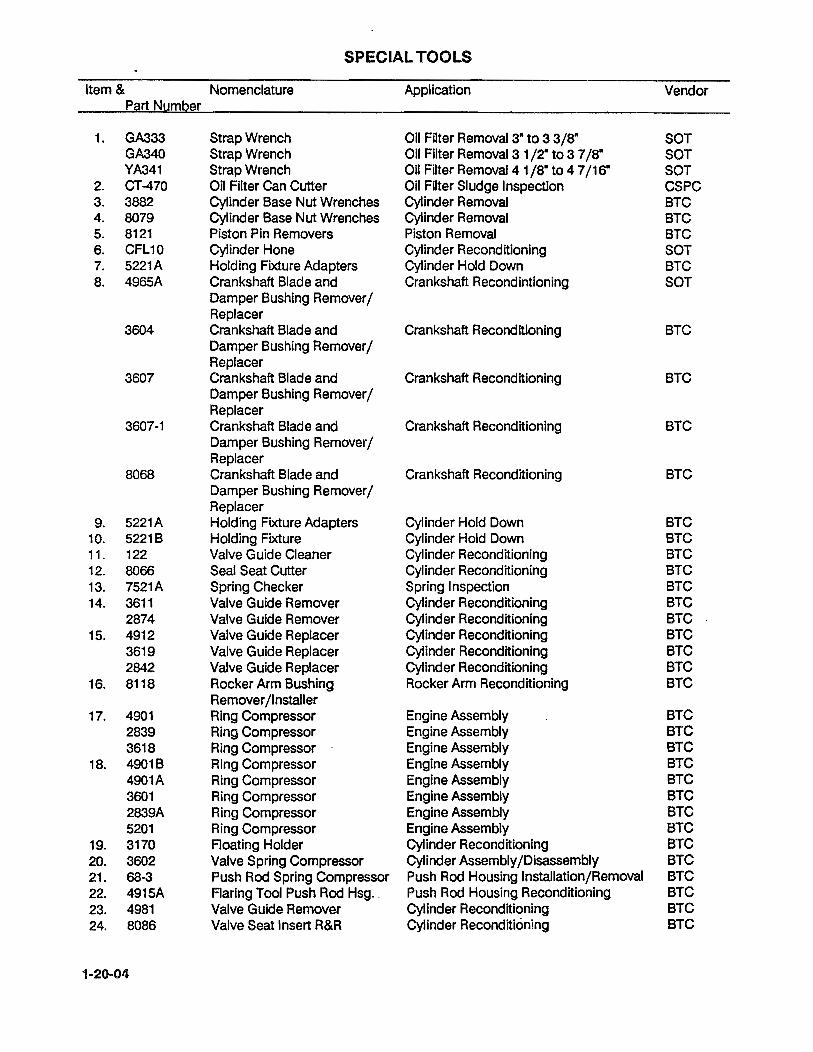
Item & Nomenclature Application Vendor Part Number
1. GA333 Strap Wrench Oil Filter Removal 3" to 3 3/8" SOT GA340 Strap Wrench Oil Filter Removal 3 1/2" to 3 7/8" SOT YA341 Strap Wrench Oil Filter Removal 4 1/8" to 4 7/16" SOT
2. CT-470 Oil Filter Can Cutter Oil Filter Sludge Inspection CSPC 3. 3882 Cylinder Base Nut Wrenches Cylinder Removal BTC 4. 8079 Cylinder Base Nut Wrenches Cylinder Removal BTC 5. 8121 Piston Pin Removers Piston Removal BTC 6. CFL10 Cylinder Hone Cylinder Reconditioning SOT 7. 5221A Holding Fixture Adapters Cylinder Hold Down BTC 8. 4965A Crankshaft Blade and Crankshaft Recondintioning SOT
Damper Bushing Remover / Replacer
3604 Crankshaft Blade and Crankshaft Reconditioning BTC Damper Bushing Remover / Replacer
3607 Crankshaft Blade and Crankshaft Reconditioning BTC Damper Bushing Remover / Replacer
3607-1 Crankshaft Blade and Crankshaft Reconditioning BTC Damper Bushing Remover j Replacer
8068 Crankshaft Blade and Crankshaft Reconditioning BTC Damper Bushing Remover / Replacer
9. 5221A Holding Fixture Adapters Cylinder Hold Down BTC 10. 5221B Holding Fixture Cylinder Hold Down BTC 11. 122 Valve Guide Cleaner Cylinder Reconditioning BTC 12. 8066 Seal Seat Cutter Cylinder Reconditioning BTC 13. 7521 A Spring Checker Spring Inspection BTC 14. 3611 Valve Guide Remover Cylinder Reconditioning BTC
2874 Valve Guide Remover Cylinder Reconditioning BTC 15. 4912 Valve Guide Replacer Cylinder Reconditioning BTC
3619 Valve Guide Replacer Cylinder Reconditioning BTC 2842 Valve Guide Replacer Cylinder Reconditioning BTC
16. 8118 Rocker Arm Bushing Rocker Arm Reconditioning BTC Remover jlnstaller
17. 4901 Ring Compressor Engine Assembly BTC 2839 Ring Compressor Engine Assembly BTC 3618 Ring Compressor Engine Assembly BTC
18. 4901B Ring Compressor Engine Assembly BTC 4901A Ring Compressor Engine Assembly BTC 3601 Ring Compressor Engine Assembly BTC 2839A Ring Compressor Engine Assembly BTC 5201 Ring Compressor Engine Assembly BTC
19. 3170 Floating Holder Cylinder Reconditioning BTC 20. 3602 Valve Spring Compressor Cylinder Assembly jDisassembly BTC 21. 68-3 Push Rod Spring Compressor Push Rod Housing Installation/Removal BTC 22. 4915A Flaring Tool Push Rod Hsg .. Push Rod Housing Reconditioning BTC 23. 4981 Valve Guide Remover Cylinder Reconditioning BTC 24. 8086 Valve Seat Insert R&R Cylinder Reconditioning BTC
1-20-04

Item & Nomenclature Application Vendor Part Number
25. 4910 Installer Valve Seat Insert Cylinder Reconditioning BTC 4956 Installer Valve Seat Insert Cylinder Reconditioning BTC
26. 8116 Common Parts Kit Cylinder Reconditioning BTC 27. 8116-24 Valve Stem Hole Reamers Cylinder Reconditioning BTC
thru 29 28. 8116-1R Reamers Cylinder Reconditioning BTC
thru 15R 29. 8116-1B Boring Bars Cylinder Reconditioning BTC
thru 15B 30. 8116-1 Expanding Guide Bodies Cylinder Reconditioning BTC
thru 16 31. 4909 Valve Seat (Straight Side) Cylinder Reconditioning BTC
Insert Cutters 4954 Valve Seat (Straight Side) Cylinder Reconditioning BTC
Insert Cutters 4985 Valve Seat (Straight Side) Cylinder Reconditioning BTC
Insert Cutters 5224 Valve Seat (Straight Side) Cylinder Reconditioning BTC
Insert Cutters 5225 Valve Seat (Straight Side) Cylinder Reconditioning BTC
Insert Cutters 32. 8135 Valve Seat (Step Side) Cylinder Reconditioning BTC
Insert Cutters 8136 Valve Seat (Step Side) Cylinder Reconditioning BTC
Insert Cutters 8138 Valve Seat (Step Side) Cylinder Reconditioning BTC
Insert Cutters 33. 2769A13 RosanR Stud Remover Stud Remover MCSC 34. 8111A Connecting Rod Fixture Connecting Rod Inspection BTC 35. 8042C Adapter Kit Connecting Rod Inspection BTC 36. 874-40,41 Reamers Conrod Bushing Connecting Rod Reconditioning BTC
5008,8071 Reamers Conrod Bushing Connecting Rod Reconditioning BTC 37. 8098 Remover/Installer Set Connecting Rod Reconditioning BTC
Connecting Rod Bushing 38. 8122A Common Drive Handle Cylinder Reconditioning BTC
8139,40,41 Pilots Cylinder Reconditioning BTC 39. 23-1 Needle Bearing Installer Needle Bearing Replacement BTC
8053 Needle Bearing Installer Needle Bearing Replacement BTC 40. 8OnA&B Bushing R/R Set Crankshaft Reconditioning BTC 41. 80nC Bushing R/R Counterweight Crankshaft Reconditioning BTC 42. 8104 Engine Stand Engine Assembly/Disassembly BTC 43. n26 Tork Band Tension Adjuster Generator/Alternator Belt Tensioning BTC 44. 4973 Generator Drive Holders Generator/Alternator Disassembly BTC 45. 8156 Cylinder Heating Stand Cylinder Reconditioning BTC 46. 8093C Bearing Puller Bearing Removal Starter Outch Shaft BTC 47. 80930 Bearing Puller Bearing Removal Starter Clutch Shaft BTC 48. 5210 Differential Pressure Gauge Setting Differential Fuel Pressure BTC 49. 7251 Differential Pressure Checking Cylinder Compression BTC
Cylinder Checker 50. BT-33-73F Belt Tension Gauge Alternator/Generator Belt Adjustment BTC
1-20-05

Item & Nomenclature Application Vendor Part Number
51. BT-60C Hydraulic Valve Utter Hydraulic Utter Testing BTC Tester
52. 8091 GEN/ALTTester Checking GENIALT Output BTC 53. 360SA Timing Disc Setting Engine Timing BTC 54. 4974 Pulley Holder Sheave Removal BTC 55. 8082 Alignment Gage Bar Checking Comp & Driver Sheave BTC
Alignment 56. 8094A Crankcase Drill Fixture Crankcase Modification BTC 57. 8334 Vacuum Pump Vacuum Testing BTC 58. 61-5 Pulley Puller GENIALT Sheave Removal BTC 59. 8094B Drill Fixture Journal Bearing Modification BTC 60. 4918 Spark Plug Insert Replacer Cylinder Reconditioning BTC 61. 8064 Step Cutter Thru-Bolt Crankcase Modification BTC
8065 Step Cutter Thru-Bolt Crankcase Modification BTC 62. 504-1 Spark Plug Insert Tap Cylinder Reconditioning BTC 63. 4919 Spark Plug Insert Remover Cylinder Reconditioning BTC 64. ·8054 Slide Hammer Multi Use BTC 65. 445 Spark Plug Tap Cylinder Reconditioning BTC 66. 8074 RosanR Lock Ring Installer Stud Installation BTC 67. 505 Stud Drivers Stud Installation BTC 68. 4987 Scavenge Pump Drill Fixture Crankcase Modification BTC 69. 8025 Drill Fixture Crankcase Squirt Nozzle Replacement BTC 70. L423 Crankcase Spitter Crankcase Separation BTC 71. 5209 Propeller Shaft Oil Seal Installation of seal over Propflange BTC
Installer 72. 8048 Oil Pressure Relief Spot Removal of surface Material around BTC
Facer holes 8155 Oil Pressure Relief Spot Removal of surface Material around BTC
Facer holes 73. 8117A Runout Block Set Crankshaft Inspection BTC 74. 8087A&B Polishing Tools for Crank- Crankshaft Reconditioning BTC
shaft Bearings 75. 8165 Injector Nozzle Remover Injector Removal & Replacement BTC
and Installer 76. 8114 Crankcase thru Bolt Removers Engine Disassembly BTC n. 7912A Hex Drive Loosening Tubing "B" Nuts BTC 78. n10 Rotabroach Cutters Hole Cutting BTC 79. 1153 Puller Removal of Press Fit Parts OTC
679 Puller Removal of Press Fit Parts OTC 80. 1035 Puller Removal of Press Fit Parts OTC
927 Puller Removal of Press Fit Parts OTC 81. 1037 Puller Removal of Press Fit Parts OTC 82. 1079 Puller Removal of Press Fit Parts OTC
1063 Puller Removal of Press Fit Parts OTC 83. 115-153 Outside Micrometers Dimensional Inspection FTSC 84. 545-116 Dial Bore Gages Dimensional Inspection FTSC 85. 122-125 Blade Micrometers Dimensional Inspection FTSC 86. 126-137 Screw Thread Micrometers Dimensional Inspection FTSC
226-137 Screw Thread Micrometers Dimensional Inspection FTSC 87. 159-211 Depth Micrometers Dimensional Inspection FTSC
1-20-06
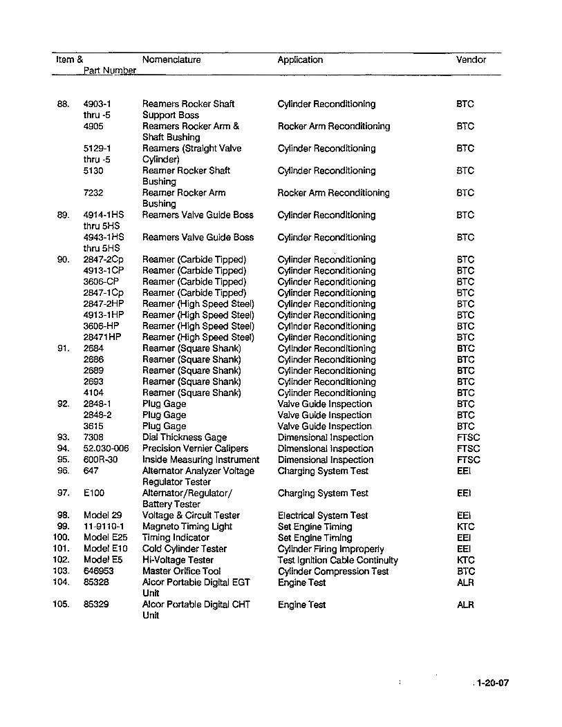
Item & Nomenclature Application Vendor Part Number
88. 4903-1 Reamers Rocker Shaft Cylinder Reconditioning BTC thru -5 Support Boss 4905 Reamers Rocker Arm & Rocker Arm Reconditioning BTC
Shaft Bushing 5129-1 Reamers (Straight Valve Cylinder Reconditioning BTC thru -5 Cylinder) 5130 Reamer Rocker Shaft Cylinder Reconditioning BTC
Bushing 7232 Reamer Rocker Arm Rocker Arm Reconditioning BTC
Bushing 89. 4914-1HS Reamers Valve Guide Boss Cylinder Reconditioning BTC
thru 5HS 4943-1HS Reamers Valve Guide Boss Cylinder Reconditioning BTC thru 5HS
90. 2847-2Cp Reamer (Carbide Tipped) Cylinder Reconditioning BTC 4913-1CP Reamer (Carbide Tipped) Cylinder Reconditioning BTC 3606-CP Reamer (Carbide Tipped) Cylinder Reconditioning BTC 2847-1Cp Reamer (Carbide Tipped) Cylinder Reconditioning BTC 2847-2HP Reamer (High Speed Steel) Cylinder Reconditioning BTC 4913-1HP Reamer (High Speed Steel) Cylinder Reconditioning BTC 3606-HP Reamer (High Speed Steel) Cylinder Reconditioning BTC 28471HP Reamer (High Speed Steel) Cylinder Reconditioning BTC
91. 2684 Reamer (Square Shank) Cylinder Reconditioning BTC 2686 Reamer (Square Shank) Cylinder Reconditioning BTC 2689 Reamer (Square Shank) Cylinder Reconditioning BTC 2693 Reamer (Square Shank) Cylinder Reconditioning BTC 4104 Reamer (Square Shank) Cylinder Reconditioning BTC
92. 2848-1 Plug Gage Valve Guide Inspection BTC 2848-2 Plug Gage Valve Guide Inspection BTC 3615 Plug Gage Valve Guide Inspection BTC
93. 7308 Dial Thickness Gage Dimensional Inspection FTSC 94. 52.030-006 Precision Vernier Calipers Dimensional Inspection FTSC 95. 600R-30 Inside Measuring Instrument Dimensional Inspection FTSC 96. 647 Alternator Analyzer Voltage Charging System Test EEl
Regulator Tester 97. E100 Alternator/Regulator / Charging System Test EEl
Battery Tester 98. Model 29 Voltage & Circuit Tester Electrical System Test EEl 99. 11-9110-1 Magneto Timing Ught Set Engine Timing KTC
100. Model E25 Timing Indicator Set Engine Timing EEl 101. Model E10 .Cold Cylinder Tester Cylinder Firing Improperly EEl 102. Model E5 Hi-Voltage Tester Test Ignition Cable Continuity KTC 103. 646953 Master Orifice Tool Cylinder Compression Test BTC 104. 85328 Alcor Portable Digital EGT Engine Test ALA
Unit 105. 85329 Alcor Portable Digital CHT Engine Test ALA
Unit
~ 1-20-07
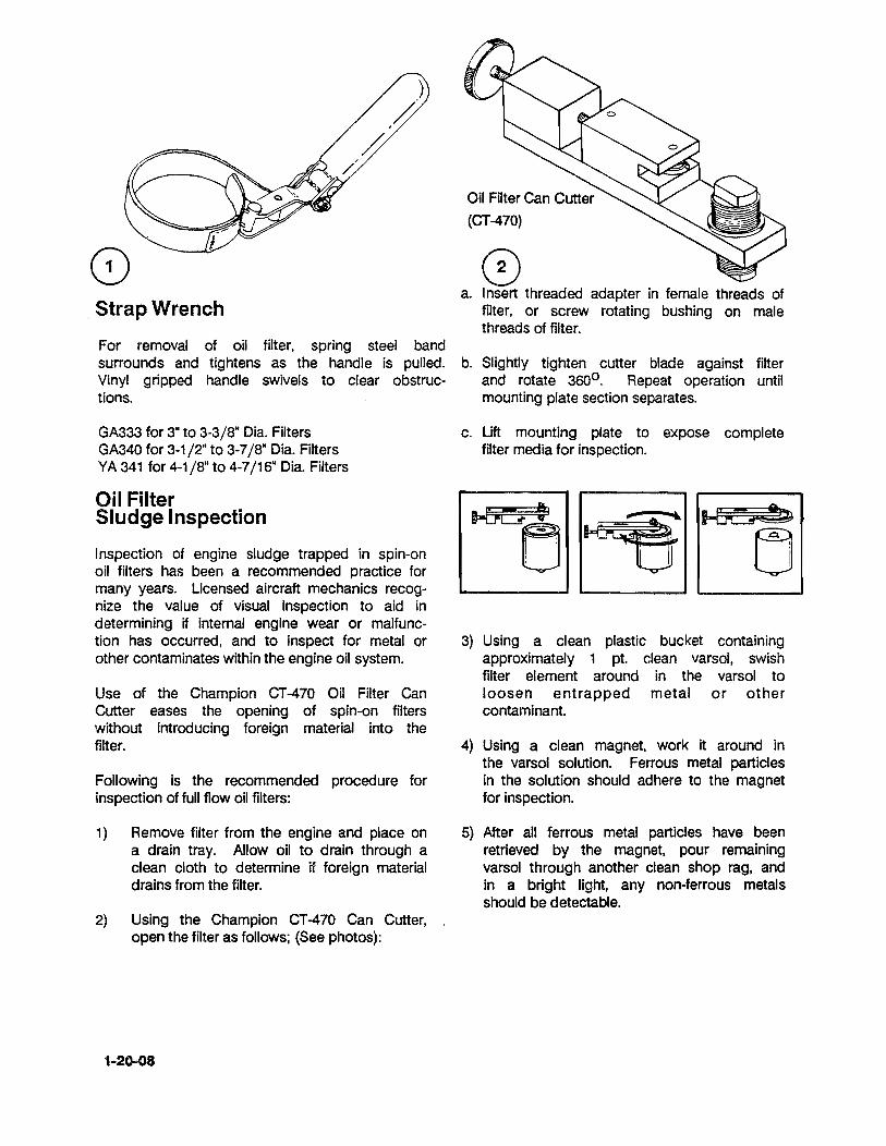
, Strap Wrench
For removal of oil filter, spring steel band surrounds and tightens as the handle is pulled. Vinyl gripped handle swivels to clear obstructions.
GA333 for 3" to 3-3/S" Dia. Filters GA340 for 3-1/2" to 3-7/S" Dia. Filters YA 341 for 4-1 /S" to 4-7/16" Dia. Filters
Oil Filter Sludge Inspection
Inspection of engine sludge trapped in spin-on oil filters has been a recommended practice for many years. Licensed aircraft mechanics recognize the value of visual inspection to aid in determining if internal engine wear or malfunction has occurred, and to inspect for metal or other contaminates within the engine oil system.
Use of the Champion CT -470 Oil Filter Can Cutter eases the opening of spin-on filters without introducing foreign material into the filter.
Following is the recommended procedure for inspection of full flow oil filters:
1) Remove filter from the engine and place on a drain tray. Allow oil to drain through a clean cloth to determine if foreign material drains from the filter.
2) Using the Champion CT -470 Can Cutter, open the filter as follows; (See photos):
1-20-08
Oil Filter Can Cutter
(CT-470)
o a. Insert threaded adapter in female threads of
filter, or screw rotating bushing on male threads of filter.
b. Slightly tighten cutter blade against filter and rotate 3600 . Repeat operation until mounting plate section separates.
c. Lift mounting plate to expose complete filter media for inspection.
3) Using a clean plastic bucket containing approximately 1 pt. clean varsol, swish filter element around in the varsol to loosen entrapped metal or other contaminant.
4) Using a clean magnet, work it around in the varsol solution. Ferrous metal particles in the solution should adhere to the magnet for inspection.
5) After all ferrous metal particles have been retrieved by the magnet, pour remaining varsol through another clean shop rag. and in a bright light. any non-ferrous metals should be detectable.

Cylinder Base Nut Wrenches 3882 Series
The 3882 Series Wrenches feature 1/2" square drive and 12-point hex sockets. The wall thickness between the hex and wrench 0.0. is closely controlled for maximum strength. Approx. 16" long overall.
3882 9/16" hex 3882-1 7/16" hex
,3882-2 1/2 II hex
3882A 9/16uhex 3882-3A 5/S" hex
3882-3 5/S" hex 3882-4 3/4" hex
Cylinder Base Nut Wrench
Special modified 3882-type wrench, this special wrench is perfect for those occasional situations when the 3882 wrench won't fit. It's a slightly different configuration, as shown.
80799/16" hex
Cylinder Base Nut Wrench
For 470 and 520 Series
The special configuration of these wrenches permits access to the cylinder base nut areas as shown. Approx. 17" long.
5203
CJ!/8" hex
5204 5/S- hex
1-20-09

Piston Pin Removers
8121 Series
Design allows piston pin removal without removing adjoining cylinder. Sizes to fit Continental engines.
Body Assy. Piston Size
8121A 8121B 8121C 81210
4-7/16" 5" 5-1/8" 5-1/4"
Cylinder Hone
Expandable racks adjust to cylinder size with universal joint action. Optional set for use on TCM cylinders.
CFL10 Standard/3" to 4-1/4" CFL1o-1 Optionalj4" to 6-1/2"
Crankshaft Blade and Dampener
. Bushing Removers/Replacers
Back-up plates and forcing screws are rugged, heat-treated alloy steel. Be sure to keep forcing screws greased.
4965A 3604 3607 3607-1 8068
1-20-10
for 5/8" 1.0. Bushing for 3/4" 1.0. Bushing for 15/32" 1.0. Bushing for GTSIO-520 for .604 1.0. Bushings
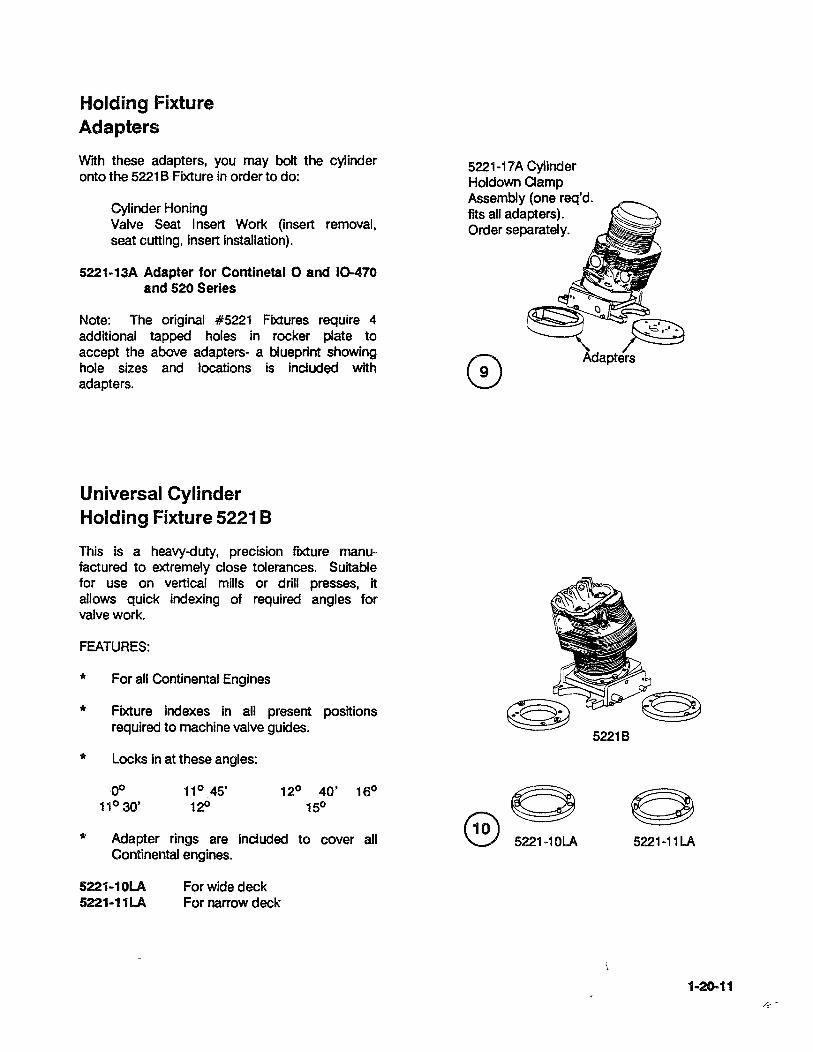
Holding Fixture Adapters
With these adapters, you may bolt the cylinder onto the 52216 Fixture in order to do:
Cylinder Honing Valve Seat Insert Work (insert removal, seat cutting, insert installation).
5221-13A Adapter for Continetal 0 and 10-470 and 520 Series
Note: The original #5221 Fixtures require 4 additional tapped holes in rocker plate to accept the above adapters- a blueprint showing hole sizes and locations is included with adapters.
Universal Cylinder Holding Fixture 5221 B
This is a heavy-duty, precision fIXture manufactured to extremely close tolerances. Suitable for use on vertical mills or drill presses, It allows quick indexing of required angles for valve work.
FEATURES:
'*
'*
'*
'*
For all Continental Engines
Fixture indexes in all present positions required to machine valve guides.
Locks in at these angles:
Adapter rings are included to cover all Continental engines.
5221-10LA 5221-11LA
For wide deck For narrow deck
5221-17A Cylinder Holdown Clamp Assembly (one req'd. fits all adapters). Order separately.
52216
5221-11 LA
1-20-11

Valve Guide Cleaner 122 Expandable type fits all Continental engines.
Seal Seat Cutter 8066 Per Continental Bulletin M76-24R.1
Modifies valve guide to comply with M76-24R.1 carbide-tipped cutter blades compensate for wear.
Spring Checker 7521 A Per Continental Bulletin M74·16
Check valve spring quickly and easily. Hydraulically actuated extremely accurate readout (0-160 pounds). Includes step gauges for all required dimensions. 7521 Checker is less step gauges.
Max. spring dimensions: Ht.-2-1/2", 0.0.-2".
(Heat-Shrink Type)
Valve Guide Removers (Cold Force Removal Type)
Tough heat-treated steel. 3611 - .375" 1.0. Guide 2874- .436/.438"1.0. Guide
1-20-12
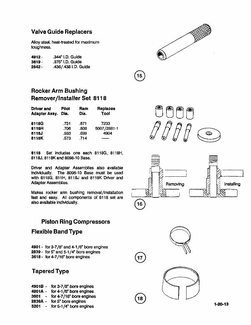
Valve Guide Replacers
Alloy steel, heat-treated for maximum toughness.
4912 - .344" 1.0. Guide 3619 - .375"1.0. Guide 2842 - .436/.438 1.0. Guide
Rocker Arm Bushing Remover/Installer Set 8118
Driver and Pilot Ram Replaces Adapter Assy. Dia. Dia. Tool
8118G .731 .871 7233 8118H .700 .808 5007/2881-1 8118J .593 .699 4904 8118K .573 .714
8118 Set Includes one each 8118G, 8118H, 8118J, 8118K and 8098-10 Base.
Driver and Adapter Assemblies also available individually. The 8098-10 Base must be used with 8118G, 811H, 8118J and 8118K Driver and Adapter Assemblies.
Makes rocker arm bushing removal/installation fast and easy. All components of 8118 set are also available individually. ®
Piston Ring Compressors
Flexible Band Type
4901 - for 3-7/8" and 4-1/6'" bore engines 2839 - for 5" and 5-1/4" bore engines 3618 - for 4-7/16" bore engines
Tapered Type
4901B - for 3-7/8" bore engines 4901A - for 4-1 /6'" bore engines 3601 - for 4-7/16'" bore engines 2839A - for S- bore engines 5201 - for 5-1/4" bore engines
tjtjtj~
!Jg§g ~
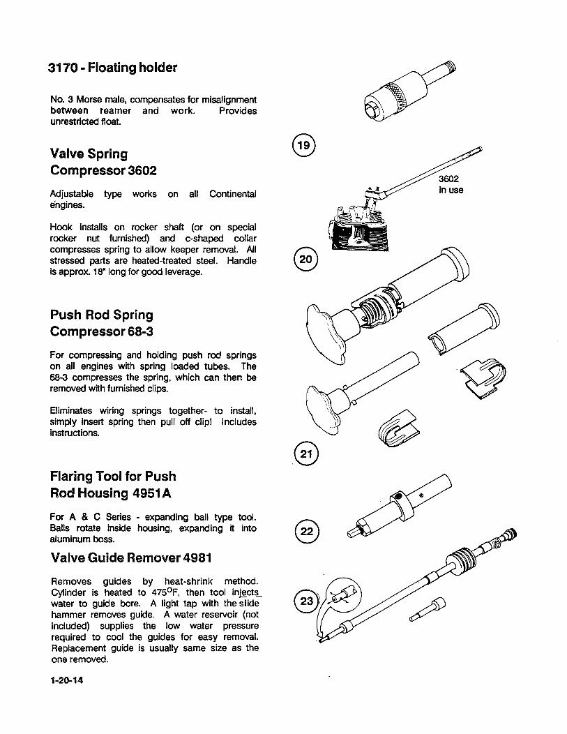
3170 - Floating holder
No. 3 Morse male, compensates for misalignment between reamer and work. Provides unrestricted float.
Valve Spring Compressor 3602
Adjustable type works on all Continental engines.
Hook Installs on rocker shaft (or on special rocker nut furnished) and c-shaped collar compresses spring to allow keeper removal. All stressed parts are heated-treated steel. Handle is approx. 18" long for good leverage.
Push Rod Spring Compressor 68-3
For compressing and holding push rod springs on all engines with spring loaded tubes. The 68-3 compresses the spring, which can then be removed with furnished clips.
Eliminates wiring springs together- to install, simply insert spring then pull off clip! Includes instructions.
Flaring Tool for Push Rod Housing 4951 A
For A & C Series - expanding ball type tool. Balls rotate inside housing, expanding it into aluminum boss.
Valve Guide Remover 4981
Removes guides by heat-shrink method. Cylinder is heated to 47SoF, then tool in~ct~ water to guide bore. A light tap with the slide hammer removes guide. A water reservoir (not included) supplies the low water pressure required to cool the guides for easy removal. Replacement guide is usually same size as the one removed.
1-20-14

Valve Seat Insert Remover and Replacer 8086
A complete tool set to remove and install valve seats by the heat-shrink method. Cylinders are heated to 5000 -5500 F. Same handle and head is used to remove and drive down seats during Installation. Mallet may be used on the handle as the seating force. Low water pressure on the order of 1 to 2 p.s.i. is all that is needed for pulling seats. This one tool set will do all Continental engines from 65 to 520 and 10-550.
Set Includes:
* (1) Handleflever assembly
* (12) Puller heads (size to fit all Continental engines
* (10) Installer pilots
* (1 ) Remover plug
* 6 feet of super flexible hose to attach to water supply
* Instructions
* Storage case.
Too! is rigged for removal. Center is plugged to route water oul thru small holes in rim of removing head.
Fig. 1.
Installer Valve Seat Inserts
4910-For 1-45/64- 0.0. Exhaust and 1-53/648
0.0. Intake Inserts. ~ Oncludes head and handle) ~
4956-For 1-3/4" 0.0. Exhaust and 1-57/648
[J1)Jl] crr:cn
En ]11 IT] [] I
TOOl is rigged for replacement. Guide on end of tool slips into valve stem ho!e for perfect alignment. No more cocked seats.
Fig. 2.
0.0. Intake Inserts. Oncludes head and handle) ) 1-20-15
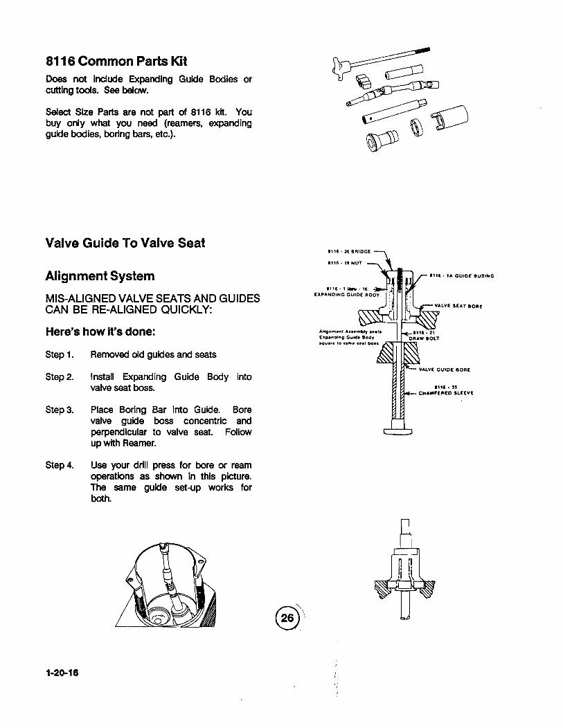
8116 Common Parts Kit Does not Include expanding Guide Bodies or cutting tools. See below.
Select Size Parts are not part of 8116 kit. You buy only what you need (reamers, expanding guide bodies, boring bars, etc.).
Valve Guide To Valve Seat
Alignment System
MIS-ALIGNED VALVE SEATS AND GUIDES CAN BE RE-ALIGNED QUICKLY:
Here's how It's done:
Step 1. Removed old guides and seats
Step 2. Install Expanding Guide Body into valve seat boss.
Step 3. Place Boring Bar into Guide. Bore valve guide boss concentric and perpendicular to valve seat. Follow up with Reamer.
Step 4. Use your drill press for bore or ream operations as shown in this picture. The same guide set-up works for both.
1-20-16
1"6· 11 NUT
1"6· 'A GUIDE 8USING
I'" . 35 CHAMFERED SL[[VE
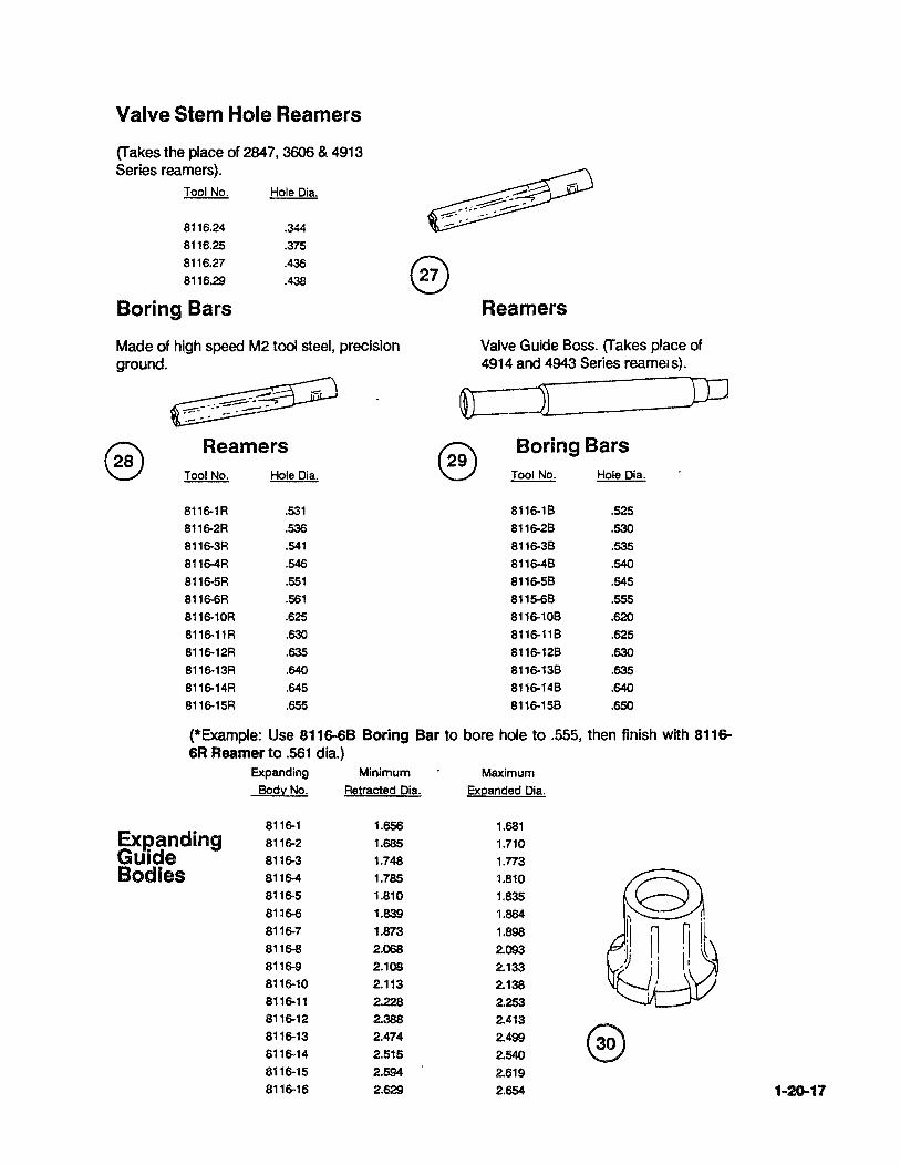
Valve Stem Hole Reamers
(Takes the place of 2847,3606 & 4913 Series reamers).
8116.24
8116.25
8116.27
8116.29
Boring Bars
Hole Dia.
.344
.375
.436
.438
Made of high speed M2 tool steel, precision ground.
@ Reamers Tool No. Hole Dia.
8116-1R .531
8116-2R .536
8116-3R .541
8116-4R .546 8116-5R .551
8116-6R .561
8116-10R .625
8116-11R .630
8116-12R .635
8116-13R .640
8116-14R .645
8116-15R .655
Reamers
Valve Guide Boss. (Takes place of 4914 and 4943 Series reamers).
~=J JD
@ Boring Bars Tool No. Hole Dia.
8116-18 .525 8116-28 .530 8116-38 .535 8116-48 .540
8116-58 .545
8115-68 .555
8116-108 .620
8116-118 .625
8116-128 .630
8116-138 .635 8116-148 .64()
8116-158 .650
(*Example: Use 8116-6B Boring Bar to bore hole to .555, then finish with 8116-6R Reamer to .561 dia.)
Expanding Minimum Maximum
Body No. Retracted Dia. Expanded Dia.
8116-1 1.656 1.681 Expanding 8116-2 1.685 1.710 Guide 8116-3 1.748 1.773 Bodies 8116-4 1.785 1.810
8116-5 1.810 1.835 81l6-6 1.839 1.864 8116-7 1.873 1.898 8116-8 2.068 2.093 8116-9 2.108 2.133 8116-10 2.113 2.138 8116-11 2.228 2.253 8116-12 2.388 2.413 8116-13 2.474 2.499 @ 8116-14 2.515 2.540 8116-15 .2.594 2.619 8116-16 2.629 2.854 1-20-17

Finish
Part No. ~ Dim. Q&
4909-8 Int 1.822 .010"
4909-9 Int 1.814 .002"
4909-12 Exh 1.689 .002"
4909-13 Exh 1.697 .010"
4954-5 Int 1.880 .005"
4954-8 Int 1.885 .01a"
Valve Seat Insert Cutters
Straight Side - Non Step
WARNING! Measure New Insert 0.0. and then select proper cutter.
Part No.
4985-5
4985-6
4985-7
4985-8
4985-9
4985-10
Straight Side Cutters
Finish
Use Dim. 9..&.
Int 2.140 .030"
Exh 1.669 .005"
Exh 1.664 ·.01a"
Exh 1.669 .015"
Exh 1.674 .020"
Exh 1.684 .030"
@ Small Large
4954-9 Int 1.885 .002" 5224-5 Int 2.522 .005" Part No. Diameter Diameter Q&.
4954-10 Int 1.895 .020" 5224-10 Int 2.527 .01a"
4954-11 Int 1.905 .030" 5224-15 Int 2.523 .015"
4954-12 Exh 1.752 .002" 5224-20 Int 2.537 .020"
4954-13 Exh 1.760 .01a" 5224-30 Int 2.547 .030" 4954-14 Exh 1.nO .020" 5225-5 Exh 1.793 .005"
4954-15 Exh 1.780 .030" 5225-10 Exh 1.798 .010"
4985-1 Int 2.115 .005" 5225-15 Exh 1.808 .015"
4985-2 Int 2.120 .010" 5225-20 Exh 1.808 .020"
4985-3 lot 2.125 .015" 5225-30 Exh 1.818 .030" 4985-4 Int 2.130 .020"
Rosan ® Stud Remover
This stud remover is for use in extracting studs from cylinder assemblies using Rosan® type Studs.
8135 1.654 1.884 STD
8135-1 1.659 1.884 .005"
8135-2 1.664 1.884 .010"
8135-3 1.669 1.884 .015"
8135-4 1.674 1.884 .020"
8135-5 1.684 1.884 .030'
8136 1.788 2.070 STD
8136-1 1.793 2.070 .005"
8136-2 1.798 2.070 .010"
Step Side Cutters
Small Large Part No. Diameter Diameter Q&
8138-3 1.803 2.070 .015"
8136-4 1.808 2.070 .020"
8138-5 1.818 2.070 .030" 8138 2.271 2.632 STD
8138-1 2.276 2.632 .005'
8138-2 2.281 2.632 .010'
8138-3 2.286 2.632 .015"
8038-4 2.291 2.632 .020"
8138-5 2.301 2.632 .030"
Using the hammer, drive the stud driver (1) over stud (2) as far as possible without making contact with the cylinder head (3). Using the ratchet or pull handle, apply a firm, constant pressure in the clockwise (tightening) direction, the serration (4) on the stud will strip. When the stud gives. reverse the ratchet and back the stud out until there are three threads still engaged in the lock ring (5). Move the stud with the driver still attached, up, down and sideways. The lock ring will pop out of the cylinder without damaging it. The stud driver is Part No. 2769A 13.
2 3
1-20-18
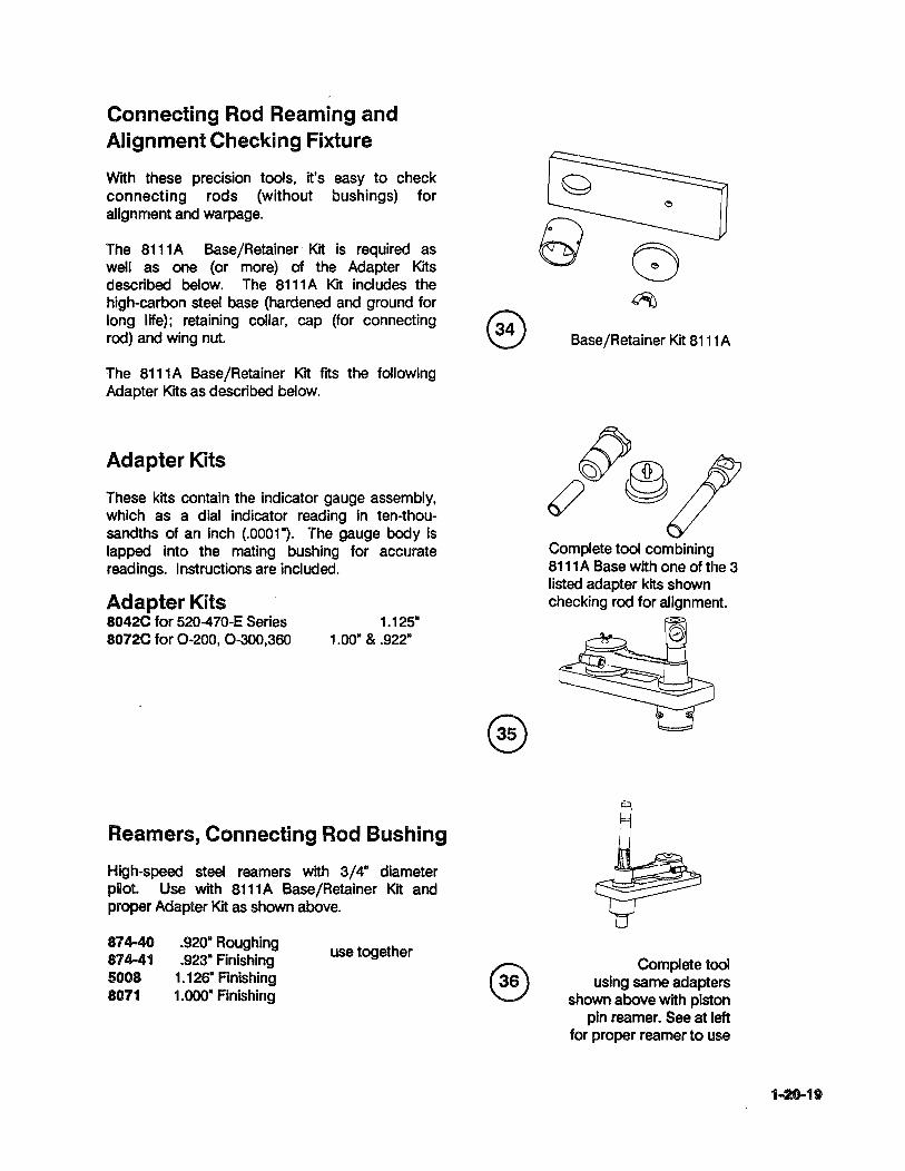
Connecting Rod Reaming and Alignment Checking Fixture
With these precision tools, it's easy to check connecting rods (without bushings) for alignment and warpage.
The 8111A Base/Retainer Kit is required as well as one (or more) of the Adapter Kits described below. The 8111A KIt includes the high-carbon steel base (hardened and ground for long life); retaining collar, cap (for connecting rod) and wing nut.
The 8111A Base/Retainer Kit fits the following Adapter Kits as described below.
Adapter Kits
These kits contain the indicator gauge assembly, which as a dial indicator reading in ten-thousandths of an inch (.0001"). The gauge body is lapped into the mating bushing for accurate readings. Instructions are included.
Adapter Kits 8042C for 520-470-E Series 8072C for 0-200, 0-300,360
1.125" 1.00· & .922"
Reamers, Connecting Rod Bushing
High-speed steel reamers with 3/4" diameter pHot. Use with 8111 A Base/Retainer Kit and proper Adapter Kit as shown above .
874-40 874-41 5008 8071
. 920· Roughing
.923" Finishing 1.126" Finishing 1.000· Finishing
use together
Base/Retainer Kit 8111A
Complete tool combining 8111 A Base with one of the 3 listed adapter kits shown checking rod for alignment.
Complete tool using same adapters
shown above wIth piston pin reamer. See at left
for proper reamer to use
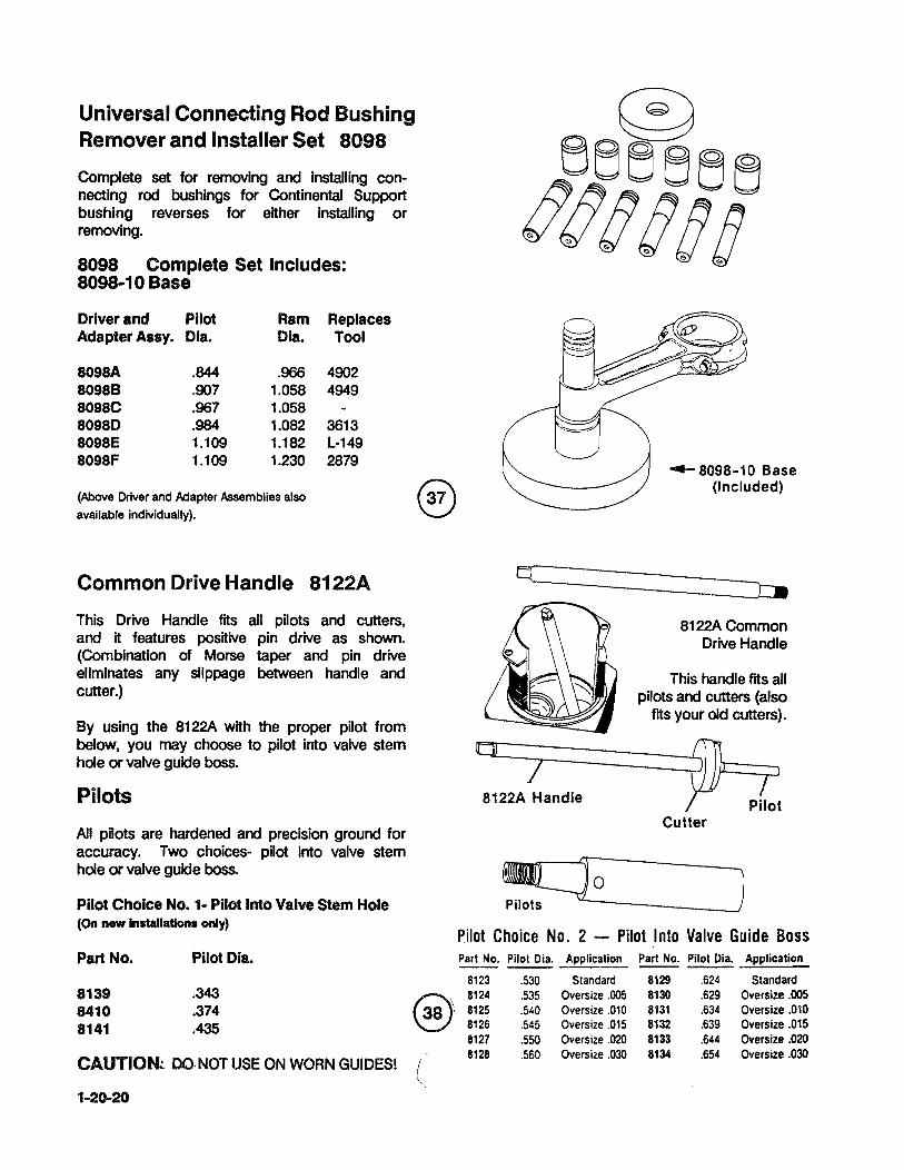
Universal Connecting Rod Bushing Remover and Installer Set 8098
Complete set for removing and Installing connecting rod bushings for Continental Support bushing reverses for either Installing or removing.
8098 Complete Set Includes: 8098-10 Base
Driver and Pilot Ram Adapter Assy. Dla. Dla.
8098A .844 .966 80988 .907 1.058 8098C .967 1.058 80980 .984 1.082 8098E 1.109 1.182 8098F 1.109 1.230
(Above Driver and Adapter Assemblies also available individually).
Replaces Tool
4902 4949
3613 L-149 2879
Common Drive Handle 8122A
This Drive Handle fits all pilots and cutters, and It features positive pin drive as shown. (Combination of Morse taper and pin drive eliminates any slippage between handle and cutter.)
By using the 8122A with the proper pilot from below, you may choose to pilot into valve stem hole or valve guide boss.
Pilots
All pilots are hardened and precision ground for accuracy. Two choices- pilot into valve stem hole or valve guide boss.
Pilot Choice No. 1- Pilot Into Valve Stem Hole (On new Installations only)
Part No.
8139 8410 8141
Pilot Dia.
.343
.374
.435
CAUTIO~ DO·NOT USE ON WORN GUIDES!
1-20-20
(
.....- 8098-10 Base (Included)
----~=-:J::II:J::II
8122A Common Drive Handle
This handle fits all pilots and cutters (also
fits your old cutters).
o __ ~ ____ ~==~ 8122A~andle / -j-:J
Pilot Cutter
~_o ____________ ~J Pilot Choice No. 2 - Pilot Into Valve Guide Boss Part No. Pilot Oia. Application ~ Pilot Oia. Application
8123 .530 Standard 8129 .624 Standard 8124 .535 Oversize .005 8130 .629 Oversize .005 8125 .540 OverSize .010 8131 .634 Oversize .010 8126 .545 Oversize .015 8132 .639 Oversize .015 8127 .550 Oversize .020 8133 .644 Oversize .020 8128 .560 Oversize .030 8134 .654 Oversize .030

Needle Bearing Installers
Precisely machined to make bearing installation fast.
23-1 .562- pUot 8053 .750- pilot
Hydraulic Crankshaft Dampener Bushing Remover/Replacer Sets 8077 A and 8077B
Remove and replace crankshaft bushings In a fraction of the time hydraulically! A few strokes of the pump handle removes or installs bushing with very little effort. Small actuating head fits In and around the crankshaft. Once the bushing Is removed (or installed), a tum of the valve returns actuator for another cycle.
8077A Includes:
10,000 p.s.l. pump and cylinder; 5-ton output cylinder; 3-ft. long flex hydraulic hose;· all adapters to fit 0-300 and 360, 470 and 520 Series.
80778 Oess hydraulics) includes:
Items shown above in SOnA except no hydraulics are furnished. The actuator head has 1/4- NPT female port for connecting to your hydraulic hose.
Counterweight ~ushing Remover/Installer 8077C
Positive guide of all components assures perfect alignment. Includes adapters for 0-300, 360, 470 and 520 Series engines.
o
1-20-21

All Position Engine Stand
Assembly-Disassembly Transportation 8104
Designed. to save time on the overhaul floor. Minimum attaching hardware allows complete engine accessibility.
Positive frame rotation (3600) locks In infinite number of positions simply by releasing handle. Engine mounting plate also rotates 3600 and locks In place with heat-treated lock pin.
Range holder is pre-drilled to accept all Continental engines. Threaded adapters Included to mount non-flanged crankshafts. Shipping weight 400 Ibs.
Tork Band Tension Adjuster 7726
Adjust belt tension without darnage to components. Use on alternators, compressors, etc. Allows grabbing difficult round components.
Generator Drive Holder
Hold drive gear for torquing or removing retaining nUl
4973 4973A
1-20-22
2.600-dla. 2.510· dla.
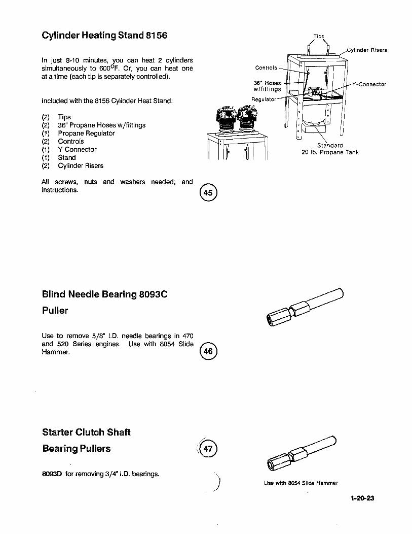
Cylinder Heating Stand 8156
In just 8-10 minutes, you can heat 2 cylinders simultaneously to 6000 F. Or, you can heat one at a time (each tip is separately controlled).
Included with the 8156 Cylinder Heat Stand:
(2) Tips (2) 36" Propane Hoses w /fittings (1) Propane Regulator (2) Controls (1) Y -Connector (1) Stand (2) . Cylinder Risers
All screws, nuts and washers needed; and ~ instructions. ~
Blind Needle Bearing 8093C
Puller
Use to remove 5/8" I.D. needle bearings in 470 and 520 Series engines. Use with 8054 Slide ~ ~mm~ ~
Starter Clutch Shaft
Bearing Pullers
8093D for removing 3/4"I.D. bearings.
)
Cylinder Risers
~~~ Controls
36' Hoses -lI-I---t--rf Y -Connector w/fittings
Regulator
Standard 20 lb. Propane Tank
Use with 8054 Slide Hammer
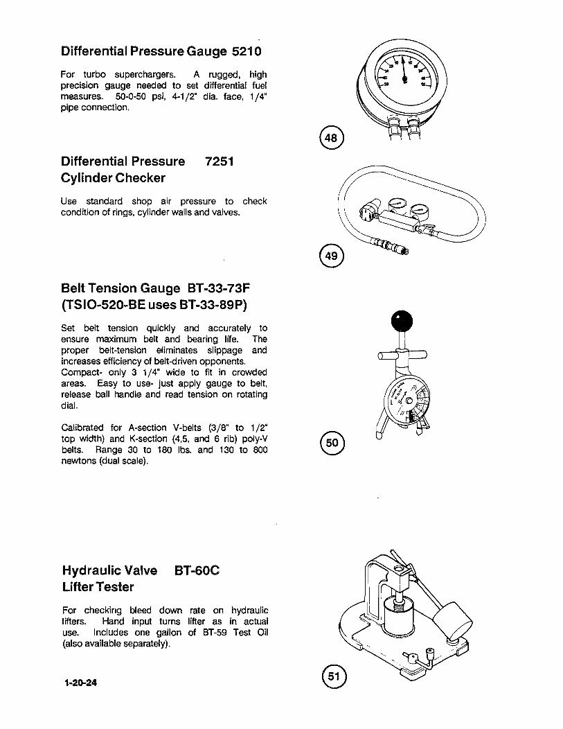
Differential Pressure Gauge 5210
For turbo superchargers. A rugged. high precision gauge needed to set differential fuel measures. 50-0-50 psi. 4-1/2" dia. face. 1/4" pipe connection.
Differential Pressure Cylinder Checker
7251
Use standard shop air pressure to check condition of rings. cylinder walls and valves.
Belt Tension Gauge BT-33-73F (TSIO-520-BE uses BT-33-89P)
Set belt tension quickly and accurately to ensure maximum belt and bearing life. The proper belt-tension eliminates slippage and increases efficiency of belt-clriven opponents. Compact- only 3 1/4" wide to fit in crowded areas. Easy to use- just apply gauge to belt. release ball handle and read tension on rotating dial.
Calibrated for A-section V-belts (3/S" to 1/2" top width) and K-section (4.5. and 6 rib) poly-V belts. Range 30 to 1S0 Ibs. and 130 to SOD newtons (dual scale).
Hydraulic Valve BT-60C lifter Tester
For checking bleed down rate on hydraulic lifters. Hand input turns lifter as in actual use. Includes one gallon of 6T-59 Test Oil (also available separately).
1-20-24

In-Aircraft Alternator / Generator Tester 8091
Replace test bench. Uses aircraft's own engine to check systems and tests without component removal. Long leads permit tester to remain in cockput during testing.
* Voltage output * Stator * Windings
* Rotor * Brushes * Field Input * Diodes
Features 0-3Ov DC voltmeter; 10-0-10 amp DC ammeter; circuit breaker protected. Two point hook-up- field term, and cigarette lighter.
Engine Timing Disc 3608A
For all engines- universal application from J3 to DCS. Fastens to prop tip and accurate to.±. 1/4 degree. Includes piston stop 360SA-1S.
Pulley Holder 4974
For holding 2-1/2" to 3-1/2" dia. pulleys grip in pulley groove.
Pulley Alignment Gage Bar 8082
The 8082 gage bar allows a quick and easy alignment check between driver sheave and compressor sheave.
Used when installing air conditioning on models 10-520 and TSI0-520. Includes adapter sleeve for 1/2" v-belts.
n /~

Crankcase Drill Fixture 8094A
For Starter Clutch Adapter
Per Continental Bulletin 79-1 0
Modifies crankcase by drilling extra oil passage from rear main to starter bushing area.
Vacuum Pump 8334
This new heavy-duty vacuum pump is designed for one-hand operation. Heavy steel wall; 0-30 in Hg; nozzle fits several sizes of tubing.
Generator Pulley Puller 61-5
Quick removes pulleys from 2-1/2" to 5" diameter. Applies even pressure on outside of pulley in pulley groove. All components are tough, heat-treated alloy steel.
Bearing and Bushing 8094B Drill Fixture Per Continental Bulletin 79-1 0 Use to reqork your present stock of main journal bearings and starter shaft bushings. Use Bearing Puller 8093B (see at right).
1-20-28
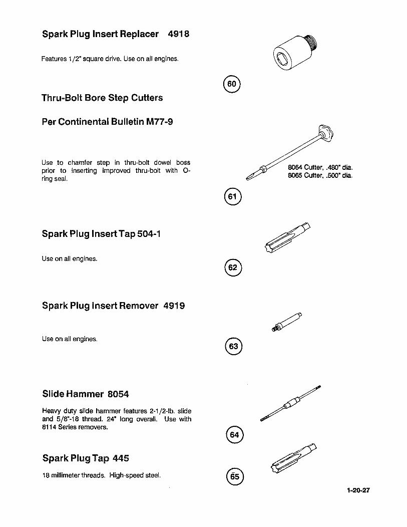
Spark Plug Insert Replacer 4918
Features 1/2· square drive. Use on all engines.
Thru .. Bolt Bore Step Cutters
Per Continental Bulletin M77-9
Use to chamfer step in thru-bolt dowel boss prior to inserting improved thru-bolt with 0-ring seal.
Spark Plug Insert Tap 504-1
Use on all engines.
Spark Plug Insert Remover 4919
Use on all engines.
Slide Hammer 8054
Heavy duty slide hammer features 2-1/2-lb. slide and 5/8"-18 thread. 24" long overall. Use with 8114 Series removers.
Spark Plug Tap 445
18 millimeter threads. High-speed steel.
®
®
8064 Cutter, .480" dia. 8065 Cutter, .500· dia.
1-20-27
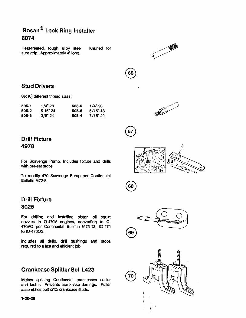
Rosan® Lock Ring Installer 8074
Heat-treated, tough alloy steel. Knurled for sure grip. Approximately 4" long.
Stud Drivers
Six (6) different thread sizes:
505-1 505-2 505-3
1/4"-28 5-16"-24 3/8"w24
Drill Fixture 4978
505-5 505-6 505-4
1/4"-20 5/16"~18 7/16"w20
For Scavenge Pump. Includes fIXture and drills with pre-set stops
To modify 470 Scavenge Pump per Continental Bulletin M72-8.
Drill Fixture 8025
For drilling and installing piston oil squirt nozzles in 0-470V engines, converting to 0-470VO per Continental Bulletin M75-13, 10-470 to 10-4700S.
Includes all drills, drill bushings and stops required to a fast and efficient job.
Crankcase Splitter Set L423
Makes splitting Continental crankcases easier and faster. Prevents crankcase damage. Puller assemblies bolt onto crankcase studs.
1-20-28

Propeller Shaft Oil Seal Installer 5209 For all flanged shafts. For installing one piece stretch seals without damaging sealing surfaces. Be sure to 011 the seal before installing.
Oil Pressure Relief Spot Facers
Positive stop to prevent excess material removal. Cutter blades are heat-treated highspeed steel.
8048 Spot Facer for 470 and 520.
Runout Block Set 8177 A
Use this set to check runout on crankshafts, etc. up to 4" diameter. Blocks are aluminum alloy with T etlon bearing surfaces. Approx. size: 4" w x S" 1 x 5" h each.
Polishing Tools for Crankshafts Bearings
Special aluminum frame and felt polishing surfaces.
8087A 1-7/S"t02-1/4"dia. 8087B 2-1/4" to 2-5/S" dia.
(Dial indicator not included)

Injector Nozzle Remover and Installer 8165
This tool allows you to remove, install and tighten injector nozzles located close to intake parts on Piper Aircraft. Torque Wrench extension allows use of 3/8" square drive torque wrench to tighten nozzles to proper specifications.
Torque wrench extension is made of heattreated steel for durability. Torque input and output Is marked on extension.
Installer Is special, thin-walled 6-pt. 1/2- hex socket.
Crankcase Thru-Bolt Removers
Use with 8054 Slide Hammer to remove stubborn bolts.
8114-8 8114-7 8114-6
Remover, 1/2"-20 threads Remover, 7/16"-20 threads Remover, 3/8"-24 threads
Hex Drive for Hex Tube Nut 7912A
Tubing nut wrench set for fuel systems, hydraulic systems and brakes.
Rotabroach Cutters 7710
These cutters cut faster and cleaner than twist drills with only a fraction of the power and effort.
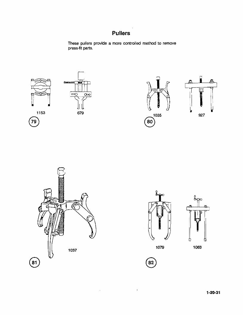
1153
@
Pullers
These pullers provide a more controlled method to remove press-fit parts.
679 ~035
~
o 0
o
1079
927
1063
1-20-31

INSPECTION INSTRUMENTS
• Outside Micrometers
Spherical Anvil Micrometers are specially useful In measuring the wall thicknesses of small parts such as sleeves, collars, tubings and various cylindrical workplaces. They are also used to measure dimensions from Inside of holes to outside edges.
"* Dial Bore Gages
Dial Bore Gages used for large volume -go, nogo· Inspections or for determination of actual dimensions. Three-point contact (two guide pins and one interchangeable rocl) assure alignment within bore. Zero point may be set with ring gage, micrometer, height master or gage blocks.
*NOTE: All precision measuring devices must have a current calibration that is traceable to the National Bureau of Standards.
115-153
545-116
1-20-32 i
! .

* Blade Micrometers Non-Rotating Spindle TYPE 122,222
For measurements of narrow grooves, keyways and other hard to reach dimensions.
* Screw Thread Micrometers
FOR MEASURING PITCH DIAMETERS TYPE 126, TYPE 226 Interchangeable V-Anvil Type
60 degree V-Anvil and Conical Spindle are made of high-grade special steel, hardened and precision ground.
*Depth Micrometers
The Depth Micrometer is one of the basic measuring tools selected by machinists.
Rachet stop for consistent and repetitive measurements.
*NOTE: All precIsion measuring devices must have a current calibration that is traceable to the National Bureau of Standards.
122-125
226-137
159-211
1-20-33

(
Reamers, Rocker Shaft Support Boss
4903-1- .645" Roughing (.609" Pilot) 4903-2- .680" Roughing (.643" Pilot) 4903-3- .703" Finishing (Use with 4903-1
& 4903-2) (.678" Pilot) 4903-4- .7OS" Finishing (Use with 4903-1
4903-2 & 4903-3) (.701" Pilot) 4903-5- .723" Finishing (Use with 4903-1,
4903-2,4903-3 & 4903-4) (.7OS- Pilot)
Reamer, Rocker Arm & Shaft Bushing
4905- .609" Std. (.594" Pilot)
@ ...
B
NOTE: 5129 SERIES ARE FOR STRAIGHT VALVE ENGINES ONLY.
5129-1- .753" Roughing (.718" Pilot) 5129-2- .788" Roughing (.751" Pilot) 5129-3- .813" Finishing (Use with
5129-1 & 5129-2) (.786" Pilot) 5129-4- .818" Finishing (Use with
5129-1 & 5129-3) (.815" Pilot) 5129-5- .833" Finishing (Use with
5129-1,5129-2,5129-3 & 5129-4) (.815" Pilot)
Reamer, Rocker Shaft Bushing
5130- .751· Std (.707" Pilot)
Reamer, Rocker Arm Bushing
7232- .751· Std. (.732" Pilot)
H
Reamers, Valve Guide Boss Use at 275 RPM maximum
USE MORSE ADAPTER
4914-1HS - .537" _____ .005" O.S. (.531" Pilot) ______ 2689 4914-2HS - .542" .010" O.S. (.534" Pilot) ______ 2689 4914-3HS - .552" .020" O.S. (.539" Pilot) ______ 2689 4914-4HS - .547" ______ .015" O.S. (.539" Pilot). 2689 4914-5HS - .561" .030" O.S. (.549" Pilot) 2689 4943-1HS - .631" .005" O.S. (.624" Pilot) 2693 4943-2HS - .636" .010" O.S. (.628" Pilot) 2693 4943-3HS - .646" .020" O.S. (.633" Pilot) 2693 4943-4HS - .641" .015" O.S. (.631" Pilot) 2693 4943-5HS - .656" .030" O.S. (.645" Pilot) 2693
1-20-34

§ ;-g B
Engine Application Chart For Valve Guide Stem Hole Reamers
REAMERS
CARBIDE- HIGH-SPEED TIPPED STEEL
2B47-2CP 2847-2HP
4913-1CP 4913-1HP
4913-1CP 4913-1HP
3606-CP 3606-HP
2B47-2CP 2847-2H.P
2847-1CP 2847-1HP
Adapt square Shank Reamers to No.2 or 3 Morse Taper
Part No. Morse 0.0. Shank Flats 2684 2 .323" .242" 2686 3 .3ST .275" 2689 3 .480" .360" 2693 3 .590" .442" 4104 Reducer Sleeve, No.2 Morse I.D. to
No.3 Morse O.D. sleeve onlywill not fit reamer shank.
NOTE. .... DO NOT use high-speed reamers on ni-resist guides.
ii
Plug Gauges, Valve Guide Stem Hole
Go and No-go Gauges are used to check for new limits (and service limits where applicable). Gauges are heattreated alloy steel, precision ground .
2848-1-2848-2-3615-
. 436" I.D. Guide
.438" I.D. Guide
.375" I.D. Guide
3
USE MORSE
CUTTING PILOT ADAPTER DIA.
.438
.344
.344
.375
.438
.436
DIA. NO.
.422 2686
.331 2684
.331 2684
.363 2684
.422 2686
.422 2686
Suggestions For Reaming Valve Guide Stem Holes
1. Use high quality cutting oil. 2. Reamers are made to cut right
hand only-do not turn backwards even a partial turn!
3. If using power, run high-speed reamers at 400 RPM maximum, and carbid~tipped at 700 RPM maximum. High-speed steel reamers for hand cutting.
4. The #5221 B universal cylinder holding fIXture is recommended for stem hole reaming, using a drill press or vertical mill.
1-20-35

*Dial Thickne$s Gage
For use in measuring wall thickness in hard to reach areas.
*Precision Vernier Calipers
Precision Vernier instruments offer a· wide range of precise tools for measuring accurately in thousandths of an inch. These include Vernier Calipers and Vernier Height gages in both the English and Metric Measure.
*Inside Measuring Instruments
Three measuring surfaces are lapped parallel to the longitudinal axis of the Micrometer, and stay aligned with the bore while measurements are taken.
Large ratchet stop provides constant measuring pressure to the wall surface, and insures repetitive reading to .0002" or .0001" (smaller ranges).
*NOTE: All precision measuring devices must have a current calibration that is traceable to the National Bureau of Standards.
1-20-36
7308
52.030-006
600 R-30

*Alternator Analyzer
Voltage Regulator Tester
For field or bench use
*
*
*
*
*
Designed to pinpoint developing problems before a total system breakdown occurs.
Oscilloscope type performance with easy to use "ok" or "Defective" presentation.
Detects failing diodes before normal indications occur.
EASY TO USE
Inductive probe clamps over wire for alternator ripple test.
Voltage regulator test leads Clip on alternator output terminal and engine ground.
*Alternator /Regulator / Battery Tester Model E100
Designed to test alternators. regulators. batteries on 12 and 24 volt systems with currents up to 32 volts DC. Has a pointer zero adjustment screw on the face of the instrument. Circuitry is entirely solid state and no battery or power source is required. Power for the unit is derived from the systems under test.
*Multiple Voltage & Circuit Tester For 12 & 24 Volts Model 29
Designed to test continuity of circuits, shorts, diodes, live circuits both low and high voltage in aircraft ignition and electronic equipment. Reads both AC and DC in all positions. Has easy-to-see bright red signal lights, with bulbs replaceable by unscrewing lenses of face of tester.
*WARNING ••• Keep equipment and personnel clear of prop area.
1-20-37
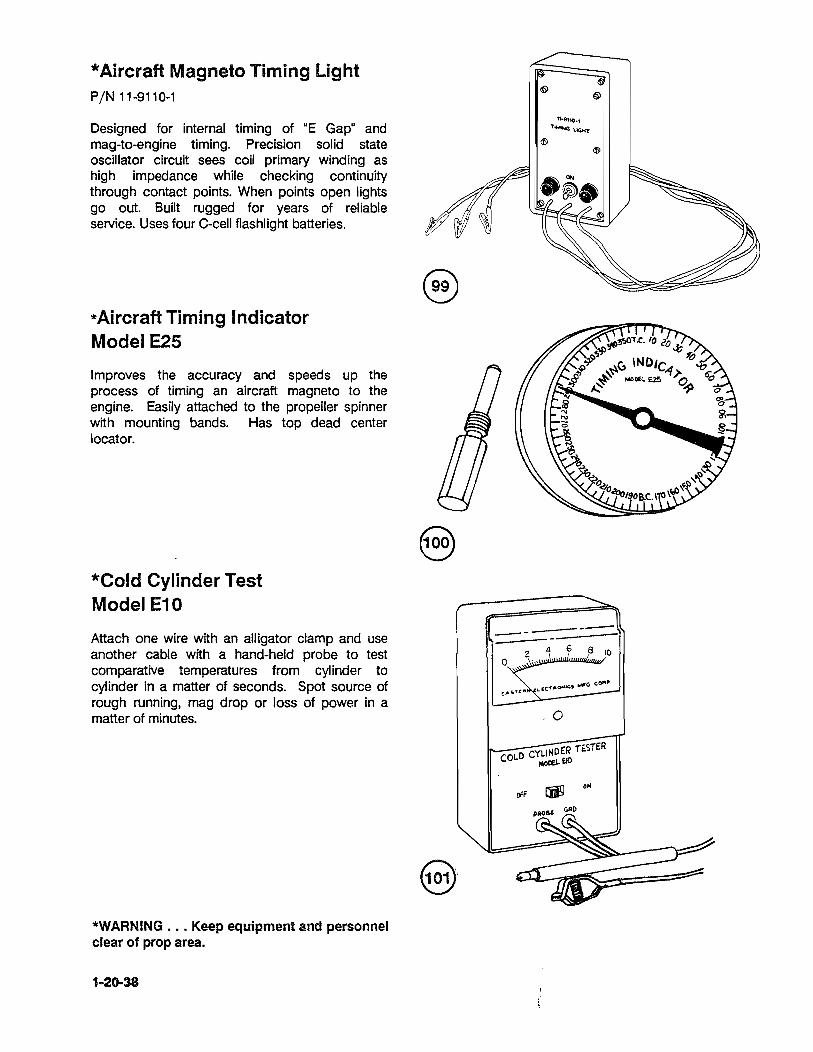
* Aircraft Magneto Timing Light PIN 11-9110-1
Designed for internal timing of "E Gap" and mag-to-engine timing. Precision solid state oscillator circuit sees coil primary winding as high impedance while checking continuity through contact points. When points open lights go out. Built rugged for years of reliable service. Uses four C-cell flashlight batteries.
*Aircraft Timing Indicator Model E25
Improves the accuracy and speeds up the process of timing an aircraft magneto to the engine. Easily attached to the propeller spinner with mounting bands. Has top dead center locator.
*Cold Cylinder Test Model E10
Attach one wire with an alligator clamp and use another cable with a hand-held probe to test comparative temperatures from cylinder to cylinder in a matter of seconds. Spot source of rough running, mag drop or loss of power in a matter of minutes.
*WARNING ••. Keep equipment and personnel clear of prop area.
1-20-38
--o
~ ~
11-9110_'
T~U(j,"'T
~ ~
-----
.0

High Tension Lead Tester Kit PIN 11-8950-2
Designed for quick and simple troubleshooting of shielded ignition leads. Accurate on even the longest leads, high voltage pulses test insulation for leak. Built-in continuity lamp provides handy test of electrical connections. Uses two c-cel! flashlight batteries. Includes top grain cowhide carrying case.
Master Orifice Tool PIN 646953
Attach to differential cylinder pressure tester to check calibration and determine the low leakage limit. (Ref. TCM Service bulletin M84-15).
* Alcor Portable Digital EGT Unit
For use with Type "K" Thermocouple. This device is lightweight 9 volt LCD unit, with a disposable battery.
Temperature Range 1 0000 -18000 F.
Part Number 85328
1-20-39

* Alcor Portable Digital CHT Unit
This device is used with Type "J" Thermocouple. It is a lightweight 9 volt LCD unit, with disposable battery.
Temperature Range 200°-600°F.
*WARNING ... Keep equipment and personnel clear of prop area.
*Federal Dimensionair Gage
For measuring out-ot-round conditions and bore diameters.
Acquire plug and ring for diameter being measured.
Part Number 85329

ITEM NO.
1
2
APPLICATION CHART SEALANTS/LUBRICANTS
TYPE/PART NUMBER APPLICATION
Grease - Molyshield · Starter Worm Gear Drive Teeth (American Lubricants Co.) and Bevel Gear Teeth
• Needle Bearings and Ball Bearings
· Valve Stems
· All ACC Drive Splines and Couplings
· Idler Gear and Support Pin
• Fuel Injection Controls, O-rings, Springs, Shafts and Bushings
REMARKS
At Engine Assembly
· Oil Pumps (pressure & scavenge) Coat Gear Cavity at Assy. of Pump
Oil - Grade 50, MHS 27 · Crankshaft Bearings At Engine Assembly (CITGO, Inc)
Connecting Rod Bearings · · Prop Driver, Driven Gears and
Bearings
· Camshaft Bearings
· Tachometer Gears and Bearings
· Accessory Spur Gear Teeth
· Quill Shaft Splines
· Prop. Gov. Trans. Collar and Sleeve
· Starter Cone, Bushing and Nut
· Starter Clutch Spring (1.0. & 0.0.)
· Pistons, Piston Pins, Piston Rings Use 600 Wt. Mobil Cylinder Oil on Chrome Plated Cylinders
· Thrust Washer At Engine Assembly
· Oil Filter Adapter Seals
· O-Rings
· Connecting Rod Nuts
1-30-01

ITEM NO. TYPE/PART NUMBER APPLICATION REMARKS
3 #646943 - Anti Seize · All Fuel Injector Nozzles Use Sparingly On Male Threads Lubricant Only At Engine Assembly · Exhaust Studs (nut end before
torquing)
, . All Class #4 Studs
· Plug Vernatherm
4 MIL·G·3545·C· Grease · All Fuel Injection Linkage At Engine Assembly (Shell #5)
O-Rings on Fuel Pumps · · Mixture Shaft Bushing
5 Alvania · Oil Seal Ups Only At Engine Assembly
(Shell #2)
6 Permatex Aviation · Lefthand (2-4-6) Crankcase At Engine Assembly
Grade 3D Parting Face (See Figure 70-20-00 Permatex, Inc. for Crankcase Threading
and Procedure. #641543 - Silk Thread · Pressure Oil Pump Covers (see
Figures 72-60-05 B & C as applicable. Use same application procedure as Crankcase Threading procedure without gasket maker.
7 #646942 Gasket Maker · Righthand (1-3-5) Crankcase Apply Sparingly Parting Face - see Figure 72-20-00 for Crankcase Threading Procedure.
8 #646942 - Gasket Maker · Starter Adapter Assembly to At Assembly
(use alone) Crankcase. (Apply thin coat to adapter).
• Engine Nose Oil Seal - Prepare Surface Using #653160 General Purpose Primer Before Application of Gasket Maker (Locquic Primer UN")
· Oil Pump Covers
• 0.0. of all Uncoated Oil Seals
#646942 - Gasket Maker and · Sump to Crankcase with Gasket Gasket (Apply thin coat between gasket,
sump, gasket & crankcase)
1-30-02

ITEM NO. TYPE/PART NUMBER APPLICATION REMARKS
9 EC1252 - Putty - Seal - • Air Throttle & Fuel Metering At Assembly While Spot - 3M Brand Assembly
• Magneto Flanges
· Cylinder Deck Stud Nuts & All Thru Bolts
10 #642188-1 - Gasket Sealant · Rocker Cover Gaskets (cover side) For All Stamped (TCM) Covers
1.5 oz. tube · Gasket Cam Bore Cover At Engine Assembly
· Gasket - Idler Pin
· Oil Gage Rod Housing to Crankcase
• Gasket - Intake Manifold
· Gasket & Oil Filler Neck Holes
· All Press Type Plugs (Hubbard Sump To Crankcase Or Sump To etc.) in Parting Line Area of 3-way Crankcase To Acc Case Joints
· 2 Bolt Suction Tube Gasket At Assembly Both Sides
11 #646941 - High Strength · Cylinder Deck Studs All Models Break-a-way Torque 100 Adhesive Sealant InlLbs After 2 Hours
· Crankcase Breather Tubes At Assembly
· Bolts For Nose Seal Retainer to
Before Application Crankcase
Prepare Surface With · Squirt Nozzle #646944 - Primer
12 #646940 - FII Sealant · All Pipe Thread Fittings in Fuel Use Sparingly On Male Threads Injection System Only
NOTE: Never Use Teflon Tape On Aircraft Engine Connection Fittings.
13 #649306 - Sealant · Use as Option to #646940 FII At Assembly Sealant
· Thru Stud Holes on Accessory End of Crankcase (Apply When Installing Studs)
14 Plastic Mold Spray Silicon Mold · Ignition Harness Terminals at At Assembly Release #VS 512 (Loctite) Magneto Block End
15 (No Lubricant or Sealant) · Spark Plugs Install Without Lubricant
1-30-03

ITEM NO. TYPE/PART NUMBER APPLICATION REMARKS
16 Dow Corning · Camshaft Lobes At Engine Assembly Molykote G-N Paste
Lifter Faces · 17 Pipe Sealant - Loctite with Teflon · Use on All Pipe Threads Except as
(PST) 592 Noted
18 Releaseagen S1 - · Intake Manifold Hoses and Flex Mold Release Ducts
RELEASEAGEN, INC.
19 Aviation Engine Oil Grade 50W, · Cylinder Studs and Thru Bolts Lube Threads Before MHS 27 or24 Tightening Nuts
20 MIL-P-46002 · Engines for Temporary Storage Or Use After Test NOX RUST VCI-105 Indefinite Storage See 72-80-03 FOR
Oil Preservative Ordering Information
Rock Island Lubricant & Chemical Company
Rock Island, Illinois
21 #649306 Adhesive/Sealant · Manifold Valve to Bracket Screws At Assembly
22 Dow Corning #4 · Apply to Rubber Oil Seal of Spin on Oil Filters
23 TCM PIN 626531-1 · High Temp. Paint for Cosmetic and See 72-30-15 Enamel - Gold (1 qt) Corrosion Protection For Application
TCM PIN 626531-2 Available Tbru Enamel- Gold (1 gal) Teledyne
Continental Motors
24 TCM PIN 535001 S · Where Applicable for Safety Wiring At Assembly Lockwire -
.032 in dia Steel ,
25 "ACCELAGOLD" · Corrosion Protection Interior and See 72-30 For Application Turco Products Exterior Aluminum Parts
Tucker, GA 30084
1-30-04

CHAPTER 4 AIRWORTHINESS LIMITATIONS
4-00-01

4-00-02
INTENTIONALL Y
LEFT
BLANK
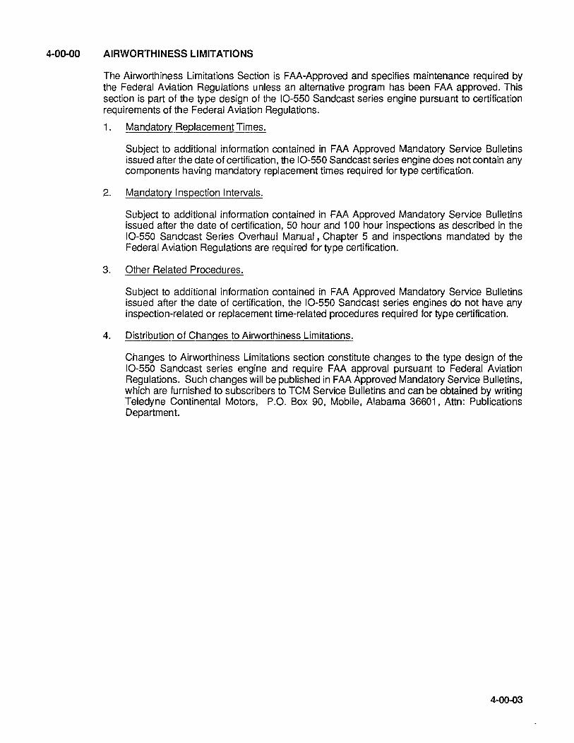
4-00-00 AIRWORTHINESS LIMITATIONS
The Airworthiness Limitations Section is FAA-Approved and specifies maintenance required by the Federal Aviation Regulations unless an alternative program has been FAA approved. This section is part of the type design of the 10-550 Sandcast series engine pursuant to certification requirements of the Federal Aviation Regulations.
1. Mandatory Replacement Times.
Subject to additional information contained in FAA Approved Mandatory Service Bulletins issued after the date of certification, the 10-550 Sandcast series engine does not contain any components having mandatory replacement times required for type certification.
2. Mandatory Inspection Intervals.
Subject to additional information contained in FAA Approved Mandatory Service Bulletins issued after the date of certification, 50 hour and 100 hour inspections as described in the 10-550 Sandcast Series Overhaul Manual, Chapter 5 and inspections mandated by the Federal Aviation Regulations are required for type certification.
3. Other Related Procedures.
Subject to additional information contained in FAA Approved Mandatory Service Bulletins issued after the date of certification, the 10-550 Sandcast series engines do not have any inspection-related or replacement time-related procedures required for type certification.
4. Distribution of Changes to Airworthiness Limitations.
Changes to Airworthiness Limitations section constitute changes to the type design of the 10-550 Sandcast series engine and require FAA approval pursuant to Federal Aviation Regulations. Such changes will be published in FAA Approved Mandatory Service Bulletins, which are furnished to subscribers to TCM Service Bulletins and can be obtained by writing Teledyne Continental Motors, P.O. Box 90, Mobile, Alabama 36601, Attn: Publications Department.
4-00-03

4-00-04
INTENTIONALLY
LEFT
BLANK
CHAPTER 5 TIME LIMITS/MAINTENANCE
CHECKS
5-00-00 GENERAL 5-10-00 TIME LIMITS/INSPECTION PROGRAM 5-20-00 SCHEDULED MAINTENANCE 5-20-01 Preflight Inspection 5-20-02 50 Hour Inspection 5-20-03 100 Hour Inspection 5-30-00 UNSCHEDULED MAINTENANCE
5-00-01

5-00-02
INTENTIONALL Y
LEFT
BLANK

5-00-00 GENERAL
The owner or operator is responsible for maintaining the engine in an airworthy condition, including compliance with all applicable Airworthiness Directives as specified in Part 39 of the Federal Aviation Regulations and "Airworthiness, Limitation" of this manual per FAR A33.4. It is also the responsibility of the owner or operator to insure that the engine is inspected in compliance with the requirements of Parts 43 and 91 of the Federal Aviation Regulations. Teledyne Continental Motors has prepared this inspection guide to assist the owner or operator in meeting their responsibilities. This Inspection guide is not intended to be all inclusive; no guide can replace the good judgement of a certified airframe and power plant mechanic, in the performance of his duties. As the one primarily responsible for the airworthiness of the airplane, the owner or operator should select only qualified personnel to maintain the airplane.
WARNING ... When performing any inspection or maintenance, always treat the engine as if the ignition switch was on. Do not stand, nor allow anyone else to stand, within the arc of the propeller, since a loose or broken wire, or a component malfunction, could cause the engine and propeller to rotate and/or start.
5-00-03

5-00-04
INTENTIONALL Y
LEFT
BLANK
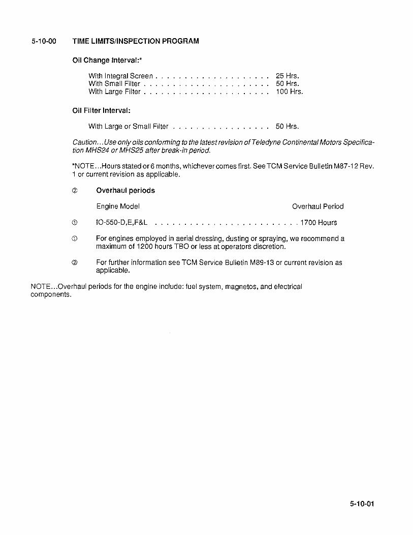
5-10-00 TIME LIMITS/INSPECTION PROGRAM
Oil Change Interval:*
With Integral Screen. With Small Filter. With Large Filter .
Oil Filter Interval:
25 Hrs. 50 Hrs. 100 Hrs.
With Large or Small Filter . . . . . . . . . . . . . . . .. 50 Hrs.
Caution ... Use only oils conforming to the latest revision of Teledyne Continental Motors Specification MHS24 or MHS25 after break-in period.
*NOTE ... Hours stated or6 months, whichever comes first. See TCM Service Bulletin M87-12 Rev. 1 or current revision as applicable.
@ Overhaul periods
Engine Model
CD IO-550-D,E,F&L
Overhaul Period
.. 1700 Hours
CD For engines employed in aerial dressing, dusting or spraying, we recommend a maximum of 1200 hours TBO or less at operators discretion.
@ For further information see TCM Service Bulletin M89-13 or current revision as applicable.
NOTE ... Overhaul periods for the engine include: fuel system, magnetos, and electrical components.
5-10-01

5-10-02
INTENTIONALL Y
LEFT
BLANK
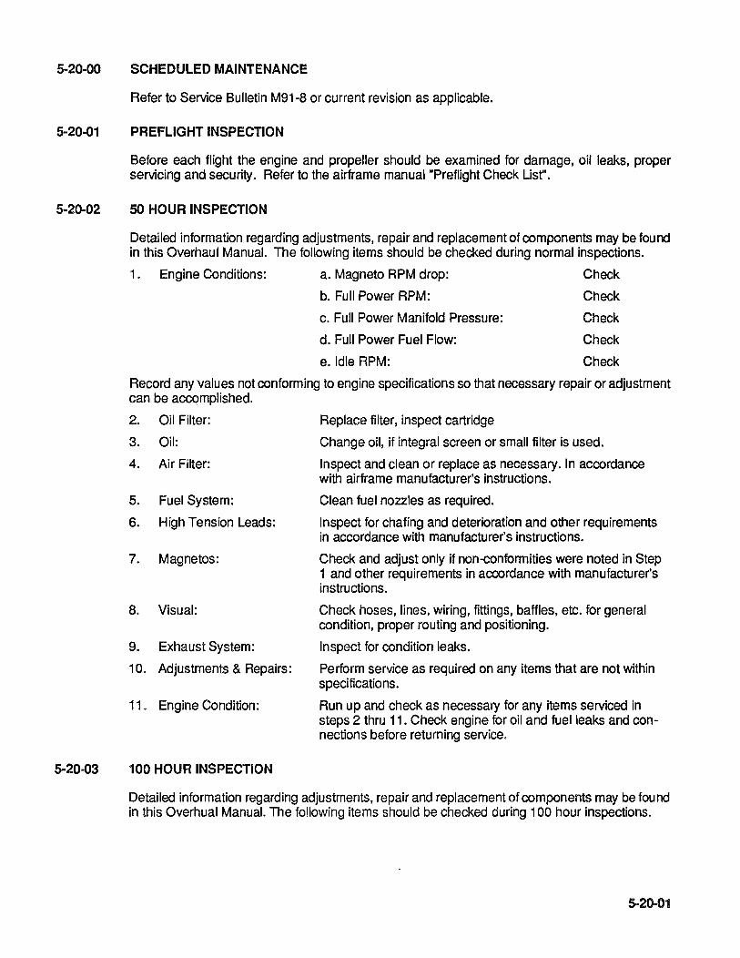
5-20-00
5-20-01
5-20-02
SCHEDULED MAINTENANCE
Refer to Service Bulletin M91-8 or current revision as applicable.
PREFLIGHT INSPECTION
Before each flight the engine and propeller should be examined for damage, oil leaks, proper servicing and security. Refer to the airframe manual "Preflight Check List".
50 HOUR INSPECTION
Detailed information regarding adjustments, repair and replacement of components may be found in this Overhaul Manual. The following items should be checked during normal inspections.
1. Engine Conditions: a. Magneto RPM drop: Check
b. Full Power RPM: Check
c. Full Power Manifold Pressure:
d. Full Power Fuel Flow:
e.ldle RPM:
Check
Check
Check
Record any values not conforming to engine specifications so that necessary repair or adjustment can be accomplished.
2. Oil Filter: Replace filter, inspect cartridge
3. Oil: Change oil, if integral screen or small filter is used.
4. Air Filter:
5. Fuel System:
6. High Tension Leads:
7. Magnetos:
8. Visual:
9. Exhaust System:
10. Adjustments & Repairs:
11. Engine Condition:
100 HOUR INSPECTION
Inspect and clean or replace as necessary. In accordance with airframe manufacturer's instructions.
Clean fuel nozzles as required.
Inspect for chafing and deterioration and other requirements in accordance with manufacturer's instructions.
Check and adjust only if non-conformities were noted in Step 1 and other requirements in accordance with manufacturer's instructions.
Check hoses, lines, wiring, fittings, baffles, etc. for general condition, proper routing and positioning.
Inspect for condition leaks.
Perform service as required on any items that are not within specifications.
Run up and check as necessary for any items serviced in steps 2 thru 11. Check engine for oil and fuel leaks and connections before returning service.
Detailed information regarding adjustments, repair and replacement of components may be fou nd in this Overhual Manual. The following items should be checked during 100 hour inspections.
5-20-01
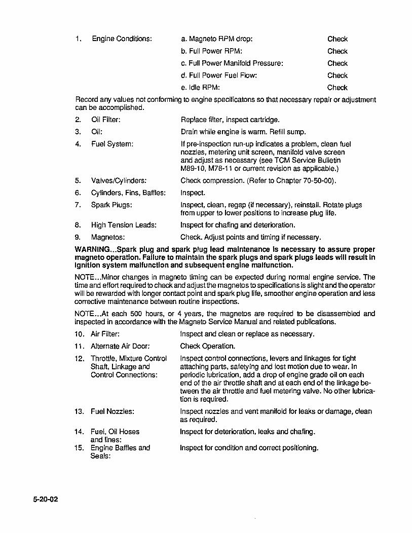
5-20-02
1. Engine Conditions: a. Magneto RPM drop:
b. Full Power RPM:
c. Full Power Manifold Pressure:
d. Full Power Fuel Flow:
e.ldle RPM:
Check
Check
Check
Check
Check
Record any values not conforming to engine specificatons so that necessary repair or adjustment can be accomplished.
2. Oil Filter: Replace filter, inspect cartridge.
3. Oil: Drain while engine is warm. Refill sump.
4. Fuel System:
5. Valves/Cylinders:
6. Cylinders, Fins, Baffles:
7. Spark Plugs:
If pre-inspection run-up indicates a problem, clean fuel nozzles, metering unit screen, manifold valve screen and adjust as necessary (see TCM Service Bulletin M89-10, M78-11 or current revision as applicable.)
Check compression. (Refer to Chapter 70-S0-00).
Inspect.
Inspect, clean, regap (if necessary), reinstall. Rotate plugs from upper to lower positions to increase plug life.
8. High Tension Leads: Inspect for chafing and deterioration.
9. Magnetos: Check. Adjust points and timing if necessary.
WARNING ... Spark plug and spark plug lead maintenance is necessary to assure proper magneto operation. Failure to maintain the spark plugs and spark plugs leads will result in Ignition system malfunction and subsequent engine malfunction.
NOTE ... Minor changes in magneto timing can be expected during normal engine service. The time and effort required to check and adjust the magnetos to specifications is slight and the operator will be rewarded with longer contact pOint and spark plug life, smoother engine operation and less corrective maintenance between routine inspections.
NOTE ... At each 500 hours, or 4 years, the magnetos are required to be disassembled and inspected in accordance with the Magneto Service Manual and related publications.
10. Air Filter: Inspect and clean or replace as necessary.
11. Alternate Air Door: Check Operation.
12. Throttle, Mixture Control Shaft, Linkage and Control Connections:
13. Fuel Nozzles:
14. Fuel, Oil Hoses and lines:
15. Engine Baffles and Seals:
Inspect control connections, levers and linkages for tight attaching parts, safetying and lost motion due to wear. In periodic lubrication, add a drop of engine grade oil on each end of the air throttle shaft and at each end of the linkage between the air throttle and fuel metering valve. No other lubrication is required.
Inspect nozzles and vent manifold for leaks or damage, clean as required.
Inspect for deterioration, leaks and chafing.
Inspect for condition and correct positioning.

5-30-00
16. Control Connections: Inspect and lubricate.
17. Exhaust: Pressure check system. Check for condition and leaks. Pay particular attention to heater muffs. Refer to airframe manufacturer for further instructions.
18. Adjustment and Repairs: Perform service as required on any items that not within specifications.
19. Engine Condition: Perform complete run-up. Check engine for fuel or oil leaks before returning to service.
UNSCHEDULED MAINTENANCE
Detailed information required for component, part replacement, system adjustments, accessory replacement and repair, top overhaul, etc., can be found in "Related Publications" listed in Chapter 1.
No unscheduled maintenance of the categories listed above should be attempted without consulting the applicable related publications.
NOTE ... ln case of engine overspeed, refer to the current Overspeed Limitations Service Bulletin M87-9 or current revision as applicable.
NOTE .. .ln case of engine overboost, refer to the current Overboost of Turbocharged Engines Service Bulletin M67-12 or current revision as applicable.
NOTE ... ln case of prop strike, refer to Service Bulletin M-84-16, or current revision as applicable.
NOTE .. .In case of lightening strike, refer to Service Bulletin M-88-9, or current revision as applicable.
5-20-03

5-20-04
INTENTIONALLY
LEFT
BLANK
5-30-00 UNSCHEDULED MAINTENANCE.
Detailed information required for component, part replacement, system adjustments, accessory replacement and repair, top overhaul, etc., can be found in "Related Publications" listed in Chapter 1.
No unscheduled maintenance of the categories listed above should be attempted without consulting the applicable related publications.
NOTE ... ln case of engine overspeed, refer to the current Overspeed Limitations Service Bulletins.
NOTE ... Refer to this manual or applicable service bulletins for proper procedures and limits.
5-30-01

5-30-02
INTENTIONALL Y
LEFT
BLANK

CHAPTER 70 STANDARD PRACTICES
70-00-00 GENERAL 70-10-00 LOCKWIRE PROCEDURE 70-20-00 CRANKCASE SEALANT AND THREADING PROCEDURE 70-30-00 APPLICATION OF ADHESIVES 70-40-00 INSTALLATION OF GASKETS 70-50-00 CYLINDER LEAKAGE CHECK 70-50-01 Leakage Checks
70-50-02 Equipment
70-50-03 Performing The Check
70-50-04 Dynamic Seal Check
70-00-01

70-00-02
INTENTIONALLY
LEFT
BLANK

70-00-00 GENERAL
To facilitate and ensure proper reinstallation, tag and/or mark all parts and hardware as to their location before they are removed or disassembled.
When removing any tubes or engine parts, look for indications of scoring, burning or other undesirable conditions. Tag any unserviceable parts or units for investigation and possible repair. Take extreme care to prevent foreign matter (Iockwire, nuts, washers, dirt, etc.) from entering the engine on or off the aircraft. Make use of protective caps, plugs, and covers to ensure openings are unexposed.
CAUTION ... Dust caps used to protect open lines must always be installed OVER the tube ends and NOT IN the tube ends. Flow through the lines will be blocked off if lines are inadvertently installed with the dust caps in the tube ends.
If anything is dropped into the engine, work must be stopped immediately and the item removed even if considerable time and labor is required.
Ensure all parts are thoroughly clean before assembling.
Alilockwire and cotter pins must fit into a recess of the nut with the other end bent such that one leg is back over the stud and the other is down flat against the nut. Use only the required corrosion resistant steel for cotter pins or lockwire.
When replacing gaskets, packings, or rubber parts, use the same type or composition as that of the gasket that was removed.
Make sure replacement nonmetallic and metallic parts are within specified cure date and show no sign of storage deterioration.
Use only a mallet of plastic or rawhide when installation of a part requires such force.
Loose fitting spline drives external to the engine which have no means of lubrication should be lubricated with an anti-seize lubricant such as molylbdenum disulfide.
70-00..Q3

70-00-04
INTENTIONALL Y
LEFT
BLANK
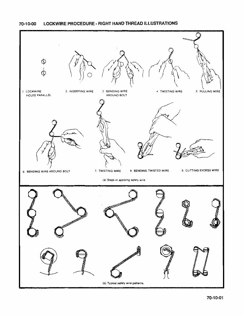
70-10-00 LOCKWIRE PROCEDURE - RIGHT HAND THREAD ILLUSTRATIONS
1. LOCKWIRE HOLES PARALLEL
2. INSERTING WIRE
6. BENDING WIRE AROUND BOLT
3 BENDING WIRE
AROUND BOLT 4. TWISTING WIRE 5. PULLING WIRE
7. TWISTING WIRE 8. BENDING TWISTED WIRE 9. CUTTING EXCESS WIRE
(a) Steps in applying safety wire.
(b) Typical safety wire patterns.

70-10-02
INTENTIONALLY
LEFT
BLANK

70-20-00 CRANKCASE SEALANT AND THREADING PROCEDURE
1. Use only full strength non-thinned Permatex aviation grade 3D. Shake or mix well before using.
WARNING ... Apply thread and permatex as illustrated.
2. Apply Permatex No. 3D to the 2-4-6 case half, only in areas where thread is shown, using short light brush strokes until an even, thin coat is obtained. The Permatex should be viscous enough that most of the brush marks disappear. If not, use a new can of aviation Permatex. (Allow the Permatex to air dry to a tacky condition before threading).
3. Apply a thin coat of TeM gasket maker PIN 646942 to 1-3-5 case half in all areas that will mate where permatex was applied on 2-4-6 case half. Gasket maker is to be applied sparingly and should be .010 to .020 of an inch thick.
4. Apply grade D silk thread PIN 641543 on 2-4-6 case half only as shown in illustration, being sure that free ends are covered by gaskets, except at oil seal. Thread only areas shown.
5. Assemble crankcase halves using bolts for alignment to prevent movement of the thread as per instuctions in Section 72-60-02 and torque all bolts in proper sequence according to figure 72-60-02 torquing sequence as soon as possible.
OPPOSITE C/C HALF
GASKET MAKER
SPACE THREAD EVENLY BETWEEN BOLT HOLES AND
EDGE OF C/C FLANGE
SILK ______ THREAD ~~~.~~~~
.34
o o
CROSS THREAD
.06-.12
1 0 e ., L~~================================================~: li
.25 THREAD C/C ACCORDING TO PROCEDURE
LISTED STEPS 1 THRU 5 .
.. AVIATION ----- ---- GRADE 0 SILK __ IIIIiIIl_ PERMATEX THREAD PIN 641543
NO. 3D
GASKET MAKER
70-20-01

70-20-02
INTENTIONALLY
LEFT BLANK
70-30-00 APPLICATION OF ADHESIVES
Adhesives and sealants will be used only in specific applications, outlined in Chapter 1 "Sealants and Lubricants".
Gasket Maker PIN 646942 - Surfaces must be clean and free of oil and grit. Apply a thin even coat of Gasket Maker between .010 and .020 of an inch thick to the surface specified in Chapter 1 "Sealants and Lubricants".
Gasket Maker is an easily workable tacky gel which can be extruded onto one side of a flange surface from a tube and evenly spread, or small parts can be covered adequately by pressing them into a saturated polyester urethane sponge or by roll coating them with a short pan roller. Once Gasket Maker has been applied, evenly torque assembly into place. Excess material can be cleaned by wiping (chlorinated solvent is helpful). Material on hands can be cleaned with waterless mechanic's hand soap followed by soap and water.
NOTE ... TCM General Purpose Primer 653160 to be used for surface preparation before applying gasket maker at the engine nose oil seal area.
70-30-01

70-30-02
INTENTIONALLY LEFT
BLANK

70-40-00 INSTALLATION OF GASKETS
All gaskets must be visually inspected prior to installation.
Following visual inspection; if the gasket shows any indication of gouges, nicks, cuts or bend and fatigue marks, immediately replace with new, pre-inspected gasket.
Gasket surfaces must be clean and free of oils and grit. Apply a thin coat of TCM Copper Coat #642188 to both sides of gasket unless otherwise specified. (Refer to Item No.1 0 in Chapter 1 "Sealants and Lubricants" for application of Copper Coat). Once Copper Coat has been applied, position gasket with the Copper Coat to its respective side, according to Chapter 1 "Sealants and Lubricants". Evenly torque assembly into place without stressing gasket.
7040-01

70-40-02
INTENTIONALL Y
LEFT
BLANK
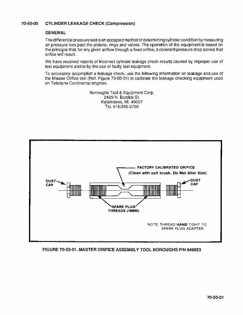
70-50-00 CYLINDER LEAKAGE CHECK (Compression)
GENERAL
The differential pressure test is an accepted method of determining cylinder condition by measuring air pressure loss past the pistons, rings and valves. The operation of the equipment is based on the principle that, for any given airflow through a fixed orifice, a constant pressure drop across that orifice will result.
We have received reports of incorrect cylinder leakage check results caused by improper use of test equipment and/or by the use of faulty test equipment.
To accurately accomplish a leakage check, use the following information on leakage and use of the Master Orifice tool (Ref. Figure 70-50-01) to calibrate the leakage checking equipment used on Teledyne Continental engines.
Borroughs Tool & Equipment Corp. 2429 N. Burdick 8t.
Kalamazoo, MI 49007 Tel. 616/345-2700
~ FACTORY CALIBRATED ORIFICE
(Clean with soft brush. Do Not Alter Size)
DUST c;;;;;;;;=== _ _ nmnmnRk' gCAUpST
CAP ~.~~~mm~----- ~
NOTE: THREAD HAND TIGHT TO SPARK PLUG ADAPTER.
FIGURE 70-50-01. MASTER ORIFICE ASSEMBLY TOOL BOROUGHS PIN 646953
70-50-01
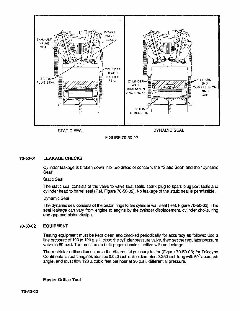
70-50-01
STATIC SEAL
LEAKAGE CHECKS
--.-....- INTAKE
CYLINDER HEAD & BARREL
SEAL
WALL DIMENSION AND CHOKE
FIGURE 70-50-02
1...-r:.,..,.-,-r-r--r"r-rT?,....,...,.-,1 S!L..oo-' 1 S TAN D
DYNAMIC SEAL
2ND COMPRESSION
RING GAP
Cylinder leakage is broken down into two areas of concern, the "Static Seal" and the "Dynamic Seal".
Static Seal
The static seal consists of the valve to valve seat seals, spark plug to spark plug port seals and cylinder head to barrel seal (Ref. Figure 70-50-02). No leakage of the static seal is permissible.
Dynamic Seal
The dynamic seal consists of the piston rings to the cylinder wall seal (Ref. Figure 70-50-02). This seal leakage can vary from engine to engine by the cylinder displacement, cylinder choke, ring end gap and piston design.
70-50-02 EQUIPMENT
70-50-02
Testing equipment must be kept clean and checked periodically for accuracy as follows: Use a line pressure of 100 to 120 p.s.i., close the cylinder pressure valve, then set the regulator pressure valve to 80 p.s.i. The pressure in both gages should stabilize with no leakage.
The restrictor orifice dimension in the differential pressure tester (Figure 70-50-03) for Teledyne Continental aircraft engines must be 0.040 inch orifice diameter, 0.250 inch long with 600 approach angle, and must flow 120 ± cubic feet per hour at 30 p.s.i. differential pressure.
Master Orifice Tool
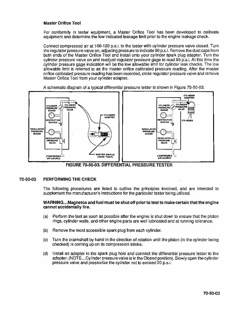
Master Orifice Tool
For conformity in tester equipment, a Master Orifice Tool has been developed to calibrate equipment and determine the low indicated leakage limit prior to the engine leakage check.
Connect compressed air at 100-120 p.s.i. to the tester with cylinder pressure valve closed. Turn the regulator pressure valve on, adjusting pressure to indicate 80 p.s.i. Remove the dust caps from both ends of the Master Orifice Tool and install onto your cylinder spark plug adapter. Turn the cylinder pressure valve on and readjust regulator pressure gage to read 80 p.s.i. At this time the cylinder pressure gage indication will be the low allowable limit for cylinder leak checks. The low allowable limit is referred to as the master orifice calibrated pressure reading. After the master orifice calibrated pressure reading has been recorded, close regulator pressure valve and remove Master Orifice Tool from your cylinder adapter.
A schematic diagram of a typical differential pressure tester is shown in Figure 70-50-03.
REGULATOR PRESSURE
GUAGE
REGULATOR PRESSURE
VALVE
COMPRESSED'::,. AIR SOURCE
f~~~:
~~ ~o,,""
(HAND TIGHT)
REGULATOR PRESSURE
GUAGE
REGULATOR PRESSURE
VALVE
COMPRESSED '::,. AIR SOURCE
FIGURE 70-50-03. DIFFERENTIAL PRESSURE TESTER
70-50-03 PERFORMING THE CHECK
CYLINOER ADAPTER
The following procedures are listed to outline the principles involved, and are intended to supplement the manufacturer's instructions for the particular tester being utilized.
WARNING ••. Magnetos and fuej must be shut off prior to test to make certain that the engine cannot accidentally fire.
(a) Perform the test as soon as possible after the engine is shut down to ensure that the piston rings, cylinder walls, and other engine parts are well lubricated and at running tolerance.
(b) Remove the most accessible spark plug from each cylinder.
(c) Turn the crankshaft by hand in the direction of rotation until the piston (in the cylinder being checked) is coming up on its compression stroke.
(d) Install an adapter in the spark plug hole and connect the differential pressure tester to the adapter. (NOTE ... Cylinder pressure valve is in the Closed position). Slowly open the cylinder pressure valve and pressurize the cylinder not to exceed 20 p.s.i.
70-50-03

70-50-04
Continue rotating the engine against this pressure until the piston reaches top dead center (TDC). Reaching TDC is indicated by a flat spot or sudden decrease in force required to turn the crankshaft. If the crankshaft is rotated too far, back up at least one-half revolution and start over again to eliminate the effect of backlash in the valve operating mechanism and to keep the piston rings seated on the lower ring lands. This is critical because the slightest movement breaks this piston ring sealing and allows the pressure to drop.
CAUTION ... Care must be exercised in opening the cylinder pressure valve, since sufficient air pressure will be built up in the cylinder and cause it to rotate the crankshaft if the piston is not at TDC. It is recommended that the propeller be secured during check to prevent possible rotation.
(e) Open the cylinder pressure valve completely. Check the regulator pressure gage and adjust, if necessary, to 80 p.s.i.
(f) Observe the pressure indication on the cylinder pressure gage. The difference between this pressure and the pressure shown by the regulator pressure gage is the amount of leakage through the cylinder. If the cylinder pressure gage reading is higher than the previously determined master orifice calibrated pressure reading, proceed to the next cylinder leak check. If the cylinder pressure gage reading is lower, proceed with the following.
Static Seal Check (Figure 70-50-05)
(g) The source of air leakage should first be checked for the static seal. Positive identification of static seal leakage is possible by listening for air flow sound at the exhaust or induction system cylinder port. When checking for cylinder head to barrel leakage, use a soapy solution between the fins and watch for bubbles. Use a soapy solution also around both spark plug seals for leakage. NO LEAKAGE IS ALLOWED IN STATIC SEALS.
(h) If leakage is occurring in the intake or exhaust valve areas, it may be possible to correct a low reading by staking the valves. This is accomplished by placing a fiber drift on the rocker arm directly over the valve stem and tapping the drift several times with a hammer to dislodge any foreign material that may be between the valve face and seat.
CAUTION. .. When correcting a low reading in this manner, rotate the propeller so the piston will not be at TDC. This is necessary to prevent the valve from striking the top of the piston in some engines. Rotate the propeller again before rechecking leakage to reset the valves in the normal manner. Do not allow the fiber drift to contact the valve spring retainer.
NOTE ... When the rocker cover is removed, inspect valve springs, valve retainers, and valve stem for wear. This may have contributed to the valve leakage.
(i) If leakage is noted between the cylinder head and barrel, REPLACE THE CYLINDER. If leakage cannot be corrected at the valves by "staking", the cylinder must be removed and repaired before a Dynamic Seal Check.
NOTE ... When the cylinder is removed, with the spark plugs installed, inspection can be accomplished by filling the inverted cylinder bore with nonflammable solvent and then inspected for leaks at the static seal areas.
(j) If the cylinder was removed for static leakage, replacement or repair, inspect piston ring gap and cylinder wall for tolerance (Ref. Dynamic Seal, Figure 70-50-02). Once the piston and the cylinder have been cleaned, inspected, and ring gap tolerances have been met, reassemble to the engine.
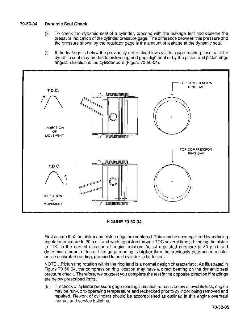
70-50-04 Dynamic Seal Check
(k) To check the dynamic seal of a cylinder, proceed with the leakage test and observe the pressure indication of the cylinder pressure gage. The difference between this pressure and the pressure shown by the regulator gage is the amount of leakage at the dynamic seal.
(I) If the leakage is below the previously determined low cylinder gage reading, loss past the dynamic seal may be due to piston ring end gap alignment or by the piston and piston rings angular direction in the cylinder bore (Figure 70-50-04).
r TOP COMPRESSION RING GAP
T.O.C.
rf\ 0
DIRECTION OF
MOVEMENT
RING GAP r TOP COMPRESSION
T.O.C.
/\1 0 DIRECTION
OF MOVEMENT
FIGURE 70-50-04
First assure thatthe piston and piston rings are centered. This may be accomplished by reducing regulator pressure to 20 p.s.i. and working piston through TDC several times, bringing the piston to TDC in the normal direction of engine rotation. Adjust regulated pressure to 80 p.s.i. and determine amount of loss. If the gage reading is higher than the previously determined master orifice calibrated reading, proceed to next cylinder to be tested.
NOTE ... Piston ring rotation within the ring land is a normal design characteristic. As illustrated in Figure 70-50-04, the compression ring location may have a direct bearing on the dynamic seal pressure check. Therefore, we suggest you complete the test in the opposite direction if readings are below prescribed limits.
(m) If recheck of cylinder pressure gage reading indication remains below allowable loss, engine may be run-up to operating temperature and rechecked prior to cylinder being removed and repaired. Rework of cylinders should be accomplished as outlined in this engine overhaul manual and service bulletins.
70-50-05
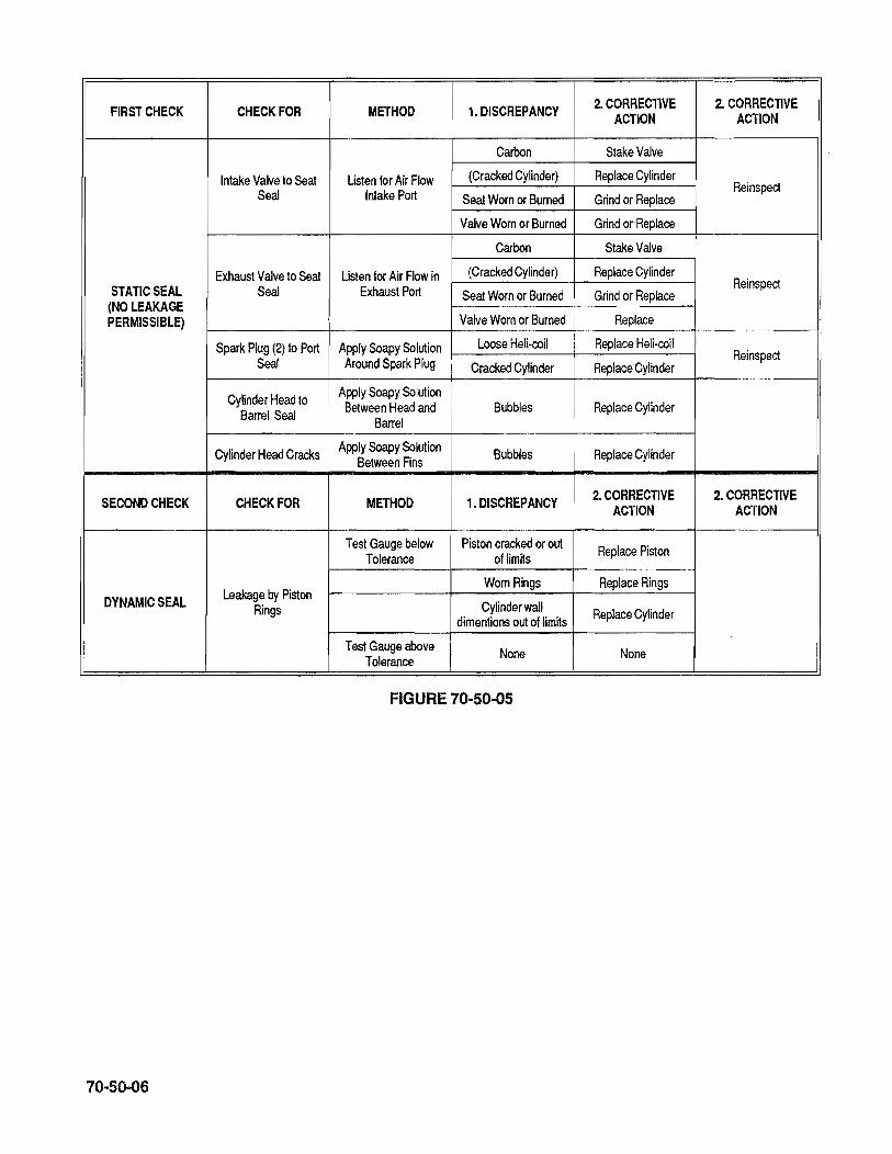
FIRST CHECK CHECK FOR METHOD 1. DISCREPANCY 2. CORRECTIVE 2. CORRECTIVE ACTION ACTION
Carbon Stake Valve
Intake Valve to Seat Listen for Air Flow (Cracked Cylinder) Replace Cylinder
Seal Intake Port Seat Worn or Burned Grind or Replace Reinspect
Valve Worn or Burned Grind or Replace
Carbon Stake Valve
Exhaust Valve to Seat Listen for Air Flow in (Cracked Cylinder) Replace Cylinder STATIC SEAL Seal Exhaust Port Seat Worn or Burned
Reinspect
(NO LEAKAGE Grind or Replace
PERMISSIBLE) Valve Worn or Burned Replace
Spark Plug (2) to Port Apply Soapy Solution Loose Heli-coil Replace Heli-coil
Seal Around Spark Plug Cracked Cylinder Replace Cylinder Reinspect
Cylinder Head to Apply Soapy Solution
Barrel Seal Between Head and Bubbles Replace Cylinder Barrel
Cylinder Head Cracks Apply Soapy Solution Bubbles Replace Cylinder Between Fins
SECOND CHECK CHECK FOR METHOD 1. DISCREPANCY 2. CORRECTIVE 2. CORRECTIVE ACTION ACTION
Test Gauge below Piston cracked or out Replace Piston Tolerance of limits
Leakage by Piston Worn Rings Replace Rings
DYNAMIC SEAL Rings Cylinder wall Replace Cylinder dimentions out of limits
Test Gauge above None None Tolerance
FIGURE 70-50-05
70-50-06
72-00-00 72-00·01
72-00-02
72-00-03
72-00-04
72-00-05
72-00-06
72-00-07
72-00-08
72-00-09
72-00-10
72-00-11
72-00-12
72-00-13
72-00-14
CHAPTER 72 ENGINE RECIPROCATING
GENERAL Introduction
Crankcase
Crankshaft
Connecting Rods
Camshaft
Pistons
Hydraulic Valve Tappets
Cylinders
Gear Train
Lubrication System
Valve Mechanism
Induction System
Exhaust System
Ignition System
72-00-01

72-00-02
INTENTIONALLY
LEFT
BLANK
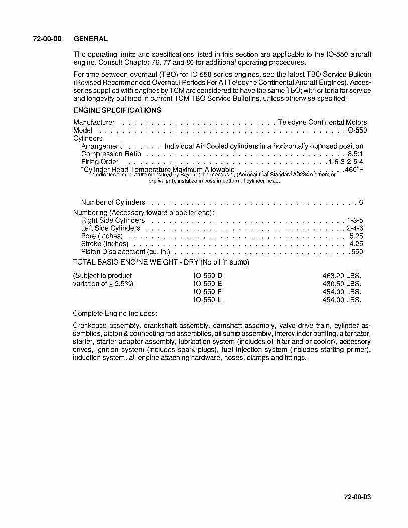
72-00-00 GENERAL
The operating limits and specifications listed in this section are applicable to the 10-550 aircraft engine. Consult Chapter 76, 77 and 80 for additional operating procedures.
For time between overhaul (TBO) for 10-550 series engines, see the latest TBO Service Bulletin (Revised Recommended Overhaul Periods For All Teledyne Continental Aircraft Engines). Accessories supplied with engines by TCM are considered to have the same TBO; with criteria for service and longevity outlined in current TCM TBO Service Bulletins, unless otherwise specified.
ENGINE SPECIFICATIONS
Manufacturer .................... Teledyne Continental Motors Model ....... . ................................ 10-550 Cylinders
Arrangement . . . Individual Air Cooled cylinders in a horizontally opposed position Compression Ratio . . . . . . . . . . . . . . . . . . . . . . . . . . . . . . . . 8.5:1 Firing Order . . . . . . . . . . . . . . . . . . . . . . . . . . . . .1-6-3-2-5-4 *Cylinder Head Temoerature Maximum Allowable ................. .460°F
'Indicates temperature measured by Bayonet thermocouple. (Aeronautical Standard AS234 element or equivalent). installed in boss in bottom of cylinder head.
Number of Cylinders ........... .
Numbering (Accessory toward propeller end): Right Side Cylinders Left Side Cylinders . . . . . Bore (Inches) ....... . Stroke (Inches) ...... . Piston Displacement (cu. in.)
TOTAL BASIC ENGINE WEIGHT - DRY (No oil in sump)
(Subject to product 10-550-0 variation of ± 2.5%) 10-550-E
Complete Engine Includes:
10-550-F 10-550-L
. .. 6
. 1-3-5
.2-4-6 5.25 4.25 .550
463.20 LBS. 480.50 LBS. 454.00 LBS. 454.00 LBS.
Crankcase assembly, crankshaft assembly, camshaft assembly, valve drive train, cylinder assemblies, piston & connecting rod assemblies, oil sump assembly, intercylinder baffling, alternator, starter, starter adapter assembly, lubrication system (includes oil filter and or cooler), accessory drives, ignition system (includes spark plugs), fuel injection system (includes starting primer), induction system, all engine attaching hardware, hoses, clamps and fittings.
72-00-03

72-00-04
DOES NOT INCLUDE:
Outer cylinder baffling, prop governor, airframe to engine control cables, attaching hardware, hose clamps and fittings.
OPERATING LIMITS
ENGINE MODEL 10-550 D,E,F&l
RATED MAX. CaNT. BHP 300
Crankshaft Speed - RPM
10-550 D,E,F&L
REC. MAX CRUISE BHP 225
Rated Maximum Continuous Operation 2700 Recommended Max. for Cruising (75% Power) 2500
Intake Manifold Pressure (In. Hg.)
Maximum Take-Off .............. . Maximum Continuous ............ . Recommended Continuous Max. for Cruising Fuel Control System . . . . . . . . . Unmetered Fuel Pressure (P.S.I.G.) Unmetered Fuel Pressure (P.S.I.G.) .... . Fuel (Min. Grade) ............... .
Full Throttle Full Throttle See Performance Chart Continental Continuous Flow Injector Idle (600 RPM) 8.0-10.0 Take-Off 33-36 Aviation Grade 100 or 100ll
WARNING ... The use of a lower octane rated fuel can result in destruction of an engine the first time high power is applied. This would most likely occur on takeoff. If the aircraft is inadvertently serviced with the wrong grade of fuel, the fuel tank must be completely drained, properly serviced, and the proper engine inspection completed.
Oil: (First 25 hours of operation) Oil Specification ........ . Normal Service
All Temperatures ...... . Below 50°F. Ambient Air (Sea level) .. Above 30°F. Ambient Air (Sea level) .. 10-550D
Mineral (non-detergent) Oil or Corrosion Preventative Oil Corresponding to Mll-C-6529 Type II
. MHS-24 or MHS-25
· .. 15W-50, 20W-50 · .. SAE30 or 10W-30 · . . . .. . SAE50
Oil Sump Capacity (U.S. Quarts) . . . . . . . . . . . . . . . . . . . . . . . 12 7.0 6.0
Usable Oil - Quarts 20° Nose Up . . . . . . . . . . . . . . . . . . . . Usable Oil - Quarts 15° Nose Down . . . . . . . . . . . . . . . . . . . . . . . .
10-550E Oil Sump Capacity (U.S.Quarts) ............................... 12
Usable Oil - Quarts 15° Nose Up . 8.0 Usable Oil - Quarts 5° Nose Down . . . . . . . . . . . . . . . . . . . . . . . .. 8.0
10-550F Oil Sump Capacity (U.S. Quarts) . . . . . . . . . . . . . . . . . . . . . . . . . . . . . . .. 12
Usable Oil- Quarts 20° Nose Up . . . . . . . . . . . . . . . . . .. 7.0 Usable Oil - Quarts 15° Nose Down . . . . . . . . . . . . . . . . . . . . . . . . 6.0
10-550l Oil Sump Capacity (U.S. Quarts) ................................ 10
Usable Oil- Quarts 20° Nose Up . . . . .. .... . . . . .. 7.8 Usable Oil- Quarts 15° Nose Down . . . . . . . . . . . . . . . . . . . . . . .. 6.7

Max. Oil Consumption (Lb.lBHP/Hr. Max. at Rated Power at RPM)
ALL MODELS --
Oil Pressure
Idle, Minimum, psi . Normal Operation, psi.
Oil Temperature Limits
006. LBS. X % Power 100
Minimum for Take-Off . Maximum Allowable .. Recommended Cruising.
IGNITION TIMING BTC
10-550-D,E,F&L
IGNITION TIMING ° BTC
RIGHT CD
22°
. .. 10 30 to 60
. . . . . .. 24°C/75°F
. . . . . . 110°C/240°F 65.5" -76. 7C/150 ° -170°F
LEFT CD
22°
CD Magneto setting tolerance to be plus or minus one (1) degree unless otherwise noted.
ACCESSORIES
The following magnetos equipped with an appropriate harness are eligible on these engines at the indicated weight change.
WARNING ... Oil pressure is applied to the face of the accessory drive pads.
10-550 D&E TWO TCM (S1200 Series) . . 10-550 F&L Two Slick Electro (6210) '"
Optional Two TCM (S1200) . .
WT. Change
.. + 1 LB. -3 LB.
+1 LB.
The following spark plugs are approved for use in all engines covered in this manual.
ALL MODELS
USE: TCM
CHAMPION
634675
RHB32E
72-00-05

72-00-01 INTRODUCTION
The arrangement and appearance of the engine components are indicated in Subsection 1-10-04. It will be observed that minimum length has been achieved by mounting the starter on right angle and by mounting the magnetos in the forward side of the accessory gear compartment formed by the crankcase castings at the rear. The magneto location also serves to shorten the high tension ignition cables as much as possible.
On the crankcase, an oil cooler is located in front of the No.5 cylinder. A full flow oil filter is used in place of the integral type screen.
Configuration differences of the 10-550 engines are the oil sump, either cast aluminum or stamped aluminum sheet metal, various induction systems, balance tubes and fuel injection assemblies.
Specific detail part differences in the 10-550 Sandcast Series will be noted in the Parts Catalog (X30606A).
72-00-02 CRANKCASE
Two aluminum alloy castings are joined along the vertical center plane to form the complete crankcase. The individual castings (with studs and inserts) will be referred to as the "left crankcase" and "right crankcase" throughout this publication.
A. Bosses molded in the crankcase castings are line bored in the assembled castings to form bearings for the camshaft and seats for precision, steel-backed, lead alloy lined crankshaft main bearing inserts. Guides are bored through lateral bosses for tappets and for the governor drive shaft. A needle bearing is pressed into the right crankcase, to the right of the rear main bearing, to support the front end of the starter shaftgear.
B. Cylinder mounting pads on the left crankcase are farther forward than the corresponding pads on the right crankcase to permit each connecting rod to work on a separate crankpin. Each pad has seven studs and two through bolts, for attaching cylinder base flanges. The propeller governor mount pad is located at the left hand lower front corner. On the right sand cast crankcase an oil cooler mounting pad is located at the front.
C. The crankcase interior is ventilated by a breather that is located on the toward 2-4-6 side.
NOTE ... Engine crankcase halves are a machined set - do not mix-match with any other set.
72-00-03 CRANKSHAFT
72-00-06
The method of numbering the crankshaft journals and cheeks is illustrated in Figure 72-00-03. Main journals, rod journals, and crankshaft cheeks are identified by letters and location numbers.
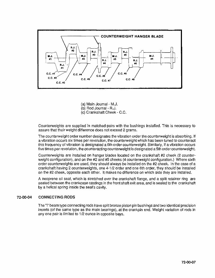
r-------~- COUNTERWEIGHT HANGER BLADE
C.C.jl3
M.J.
R.J. jl5
-t==r~-+ #3 -+-==r r==t-tR.J.
C.C.jl7
(a) Main Journal- M.J. (b) Rod Journal - R.J.
1«1
C.C. /19
(c) Crankshaft Cheek - C.C.
M.J. jl4
Counterweights are supplied in matched pairs with the bushings installed. This is necessary to assure that their weight difference does not exceed 2 grams.
The counterweight order number designates the vibration order the counterweight is absorbing. If a vibration occurs six times per revolution, the counterweight which has been tuned to counteract this frequency of vibration is designated a 6th order counterweight. Similarly, if a vibration occurs five times per revolution, the counteracting counterweight is designated a 5th order counterweight.
Counterweights are installed on hanger blades located on the crankshaft #2 cheek (2 counterweight configuration), and on the #2 and #5 cheeks (4 counterweight configuration.) Where sixth order counterweights are used, they should always be installed on the #2 cheek. In the case of a crankshaft having 2 counterweights, one 4-1/2 order and one 6th order, they should be installed on the #2 cheek, opposite each other. It makes no difference on which side they are installed.
A neoprene oil seal, which is stretched over the crankshaft flange, and a split retainer ring are seated between the crankcase castings in the front shaft exit area, and is sealed to the crankshaft by a helical spring inside the seal's cavity.
72-00-04 CONNECTING RODS
The "I" beam type connecting rods have split bronze piston pin bushings and two identical precision inserts (of the same type as the main bearings), at the crankpin end. Weight variation of rods in anyone pair is limited to 1/2 ounce in opposite bays.
72-00-07

72-00-05 CAMSHAFT
A steel alloy forging is machined on four journals, nine cam lobes and the gear mount flange at the rear end. The lobes and journals are ground and hardened. A groove around the front journal passes engine oil from the right crankcase cross passage to the left case passage. The camshaft gear is attached by four unequally spaced bolts to locate its timing mark in relation to the cam lobes.
72-00-06 PISTONS
Pistons are aluminum alloy castings with a steel insert cast into the top ring groove. The skirts are solid and have cylindrical relief cuts at the bottom to clear the crankshaft counterweights. Pistons have three ring grooves above the pin hole and one ring groove below. Compression rings are installed in the top, second and the groove below the pin hole. A center grooved and slotted oil ring is installed in the third groove, which has six oil drain holes to the interior. Weights are limited to 1/2 ounce in opposing bays. Piston pins are full floating ground steel tubes with permanently pressed-in aluminum or bronze end plugs.
72-00-07 HYDRAULIC VALVE TAPPETS
The barrel type hydraulic tappets may be removed and replaced without complete disassembly of the engine. Construction and operation of the tappets are described in Section 72-00-11.
72-00-08 CYLINDERS
72-00-08
The externally finned aluminum alloy head castings are heated and valve seat inserts and valve guides are installed before the head is screwed and shrunk onto an externally finned steel alloy barrel to make the permanent head and barrel assembly. Special 18mm helical coil thread inserts are installed in upper and lower spark plug holes. Smaller helical coils are installed in intake manifold attaching bolt holes. Both the intake and the exhaust ports are on the bottom of the head when the cylinder is installed. Exhaust valve faces are Stellite No.6 and stem tips are hardened. Valve stems are solid. Outer retainers of the two concentric springs surrounding each valve are locked to the stems by tapered, semi-circular keys which engage grooves around the stems. Rotocaps are installed on intake and exhaust valves. Inner spring retainers are pressed steel. Valve rocker covers are aluminum alloy castings. Rocker shafts are ground steel tubes with a hole drilled in one end at a 90 degree angle to the longitudinal axis and tapped for retaining screws. The two inside rocker shaft bosses are drilled for the 5/16 inch rocker shaft retaining screws. Valve rockers are steel forgings with hardened sockets and rocker faces and pressed-in bronze bearings. They are drilled for lubrication. Pushrods are constructed of steel tubes and pressed-in, hardened, forged steel ball ends, which are center drilled for oil passages. The pushrod housings are beaded steel tubes. The bead at the cylinder end retains a packing ring between two washers. The bead at the crankcase end retains a heavy spring, washer, packing, ring and second washer. The cylinders are nitrided for wear resistance.

72-00-09 GEAR TRAIN (See Figure 72-00-09).
A. When starting engine, torque is transmitted from the starter (18) through adapter components (17 thru 22) to crankshaft gear (1). As wormwheel (20) is turned, clutch spring (21) mounted on its hub, is tightened to grip knurled drum of shaftgear (22). This design eliminates wear and stress encountered in direct drive starter systems. After engine is started, spring returns to its normal position, thus disengaging starter. The shaftgear (22) is now used to transmit torque from the crankshaft gear to the generator drive pu"ey.
B. Torque from the crankshaft (2) is transmitted by the crankshaft gear (1) directly to the idler gear (12) and camshaft gear (3).
C. The idler gear, rotating in a counterclockwise direction, drives magneto drive gears (14 and 15). Optional accessories mounted on crankcase upper rear are driven by internal splines of magneto drive gears.
D. The fuel pump drive gear (23) is driven by the camshaft cluster gear (3). The splined end of the oil pump and tachometer drive gear (8) mates with the internal splines of the camshaft gear and transmits torque to the oil pump driven gear (9) and tachometer drive gear (10). The governor drive bevel gear (6) on the front of the camshaft (4) drives the governor driven bevel gear (7).
72-00-09

72-00-10
FIGURE 72-00-09 GEAR TRAIN DIAGRAM.
1. Crankcase Gear .... 2. Crankshaft . . . . . . . 3. Camshaft Cluster Gear 4. Camshaft........ 5. Hydraulic Lifter . . . . . 6. Governor Drive Bevel Gear 7. Governor Driven Be el Gear 8. Oil Pump and Tachometer Drive Shaftgear . 9. Oil Pump Driven Gear ....
10. Tachometer Drive Bevel Gear 11. Tachometer Shaftgear . . 12. Idler Gear Assembly . . . 13. Idler Gear Support Pin .. 14. Left Magneto Drive Gear. 15. Right Magneto Drive Gear 16. Starter ...... . 17. Worm Drive Shaft .. 18. Worm Shaft Spring . . 19. Starter Worm Gear .. . .... 20. Starter Worm Wheel . 21. Clutch Spring 22. Starter Shaftgear . 23. Fuel Pump Drive . .. . ....
1 :1 1 1 :0.5 1:0.5
1 :0.5 1 :1 1 :0.5 1 :0.5 1 :0.5 1 :0.5 1 :0.652
1 :1.5 1 :1.5
· 32:1 .... 32:1
· 32:1 · 2:1 · 2:1
1 :2 · 1:1

72-00-10 LUBRICATION SYSTEM (See Figure 72-00-10).
A. Oil is drawn from the sump through the suction tube to the intake side of the engine gear driven oil pump. From the outlet side of the pump, oil is directed to the oil filter chamber and tachometer drive gear. A filter by-pass valve is incorporated in the pump housing in the event that the filter becomes clogged.
B. After leaving the pump, oil is directed through passages to the right crankcase oil gallery Cylinder number 1,3 and 5 intake and exhaust tappets are lubricated by oil coming from passages leading off this gallery. Right side valve lifters and guides are lubricated by passages leading off this gallery. An oil temperature control valve is located at the front end of the right oil gallery to regulate oil temperature within specific limits. When oil reaches a temperature high enough to require cooling, the control valve expands and blocks passage, directing oil to the cooler. From the control valve cavity, oil is directed to the forward camshaft bearing. A groove in the camshaft transfers the flow of oil to a passage in the crankcase which is then directed to the left oil gallery.
C. Oil is directed to the governor drive bearing and propeller governor through passages off the left oil gallery. Control oil from the governor is channeled to the crankshaft oil transfer collar, which directs it to the crankshaft interior and on to the propeller.
D. Passageways from the left oil gallery direct oil to the main bearings and 2,4,6 side valve tappets. Four drilled passages, radiating from the rear main bearing conduct lubrication oil to the fuel pump drive, right and left magneto drives, accessory drives and to startershaftgear. An intersecting passage directs oil to the idle gear support.
E. The pistons are cooled and cylinder walls lubricated by means of squirt nozzles which direct a stream of oil on the inner dome of each piston. These nozzles are fed by a groove cut in the main bearing saddles.
72-00-11

TO PROPELLER--.
GOVERNOR PAD
72-00-12
OIL TRANSFER COLLAR
---- OIL SUCTION -.-.-.- OIL THRU RELIEF VALVE .••••••••••• OIL THRU OIL TEMPERATURE
CONTROL VALVE --- OIL UNDER PRESSURE ----_ •• _- OIL FROM GOVERNOR
OIL COOLER
SUMP 01 L PICK·UP
Figure 72-00-10 Lubrication System
ACCESSORY DRIVES
IDLER
OIL SCREEN
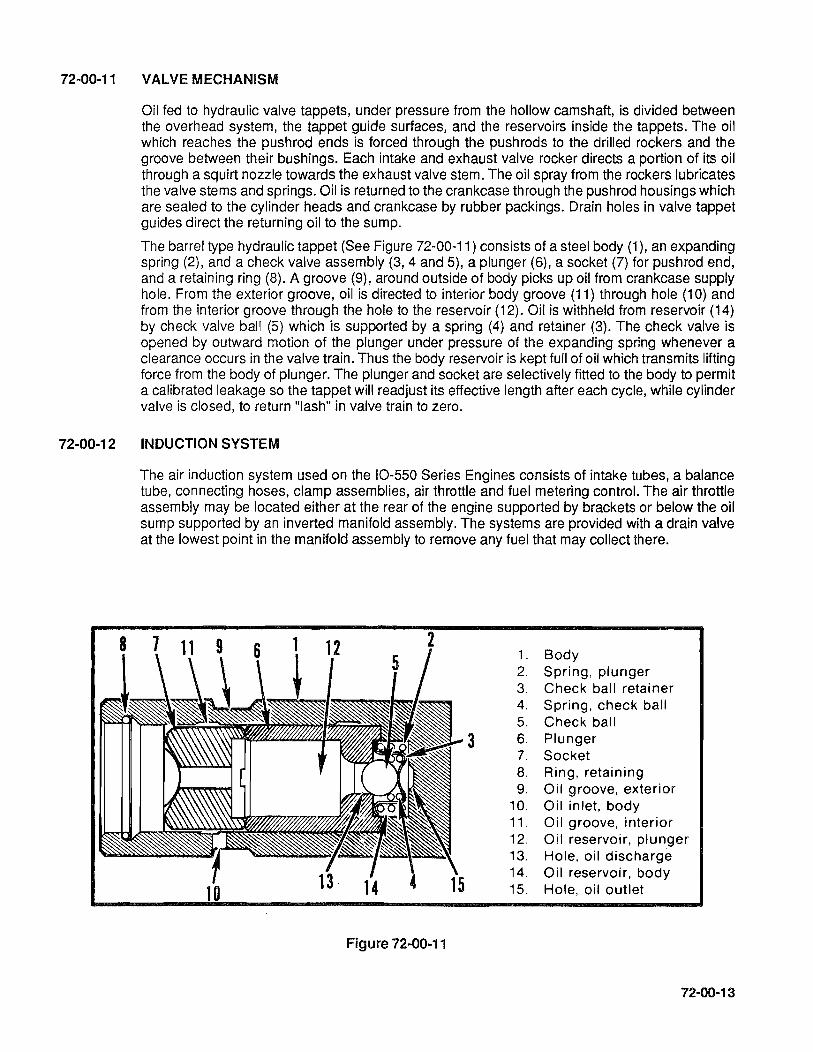
VALVE MECHANISM
Oil fed to hydraulic valve tappets, under pressure from the hollow camshaft, is divided between the overhead system, the tappet guide surfaces, and the reservoirs inside the tappets. The oil which reaches the pushrod ends is forced through the push rods to the drilled rockers and the groove between their bushings. Each intake and exhaust valve rocker directs a portion of its oil through a squirt nozzle towards the exhaust valve stem. The oil spray from the rockers lubricates the valve stems and springs. Oil is returned to the crankcase through the pushrod housings which are sealed to the cylinder heads and crankcase by rubber packings. Drain holes in valve tappet guides direct the returning oil to the sump.
The barrel type hydraulic tappet (See Figure 72-00-11) consists of a steel body (1), an expanding spring (2), and a check valve assembly (3, 4 and 5), a plunger (6), a socket (7) for pushrod end, and a retaining ring (8). A groove (9), around outside of body picks up oil from crankcase supply hole. From the exterior groove, oil is directed to interior body groove (11) through hole (10) and from the interior groove through the hole to the reservoir (12). Oil is withheld from reservoir (14) by check valve ball (5) which is supported by a spring (4) and retainer (3). The check valve is opened by outward motion of the plunger under pressure of the expanding spring whenever a clearance occurs in the valve train. Thus the body reservoir is kept full of oil which transmits lifting force from the body of plunger. The plunger and socket are selectively fitted to the body to permit a calibrated leakage so the tappet will readjust its effective length after each cycle, while cylinder valve is closed, to return "lash" in valve train to zero.
72-00-12 INDUCTION SYSTEM
The air induction system used on the 10-550 Series Engines consists of intake tubes, a balance tube, connecting hoses, clamp assemblies, air throttle and fuel metering control. The air throttle assembly may be located either at the rear of the engine supported by brackets or below the oil sump supported by an inverted manifold assembly. The systems are provided with a drain valve at the lowest point in the manifold assembly to remove any fuel that may collect there.
2 1. Body 2. Spring, plunger 3. Check ball retainer 4. Spring, check ball 5. Check ball
3 6. Plunger 7. Socket 8. Ring, retaining 9. Oil groove, exterior
10. Oil inlet. body 11. Oil groove, interior 12. Oil reservoir, plunger 13. Hole, oil discharge 14. Oil reservoir, body 15. Hole, oil outlet
Figure 72-00-11
72-00-13
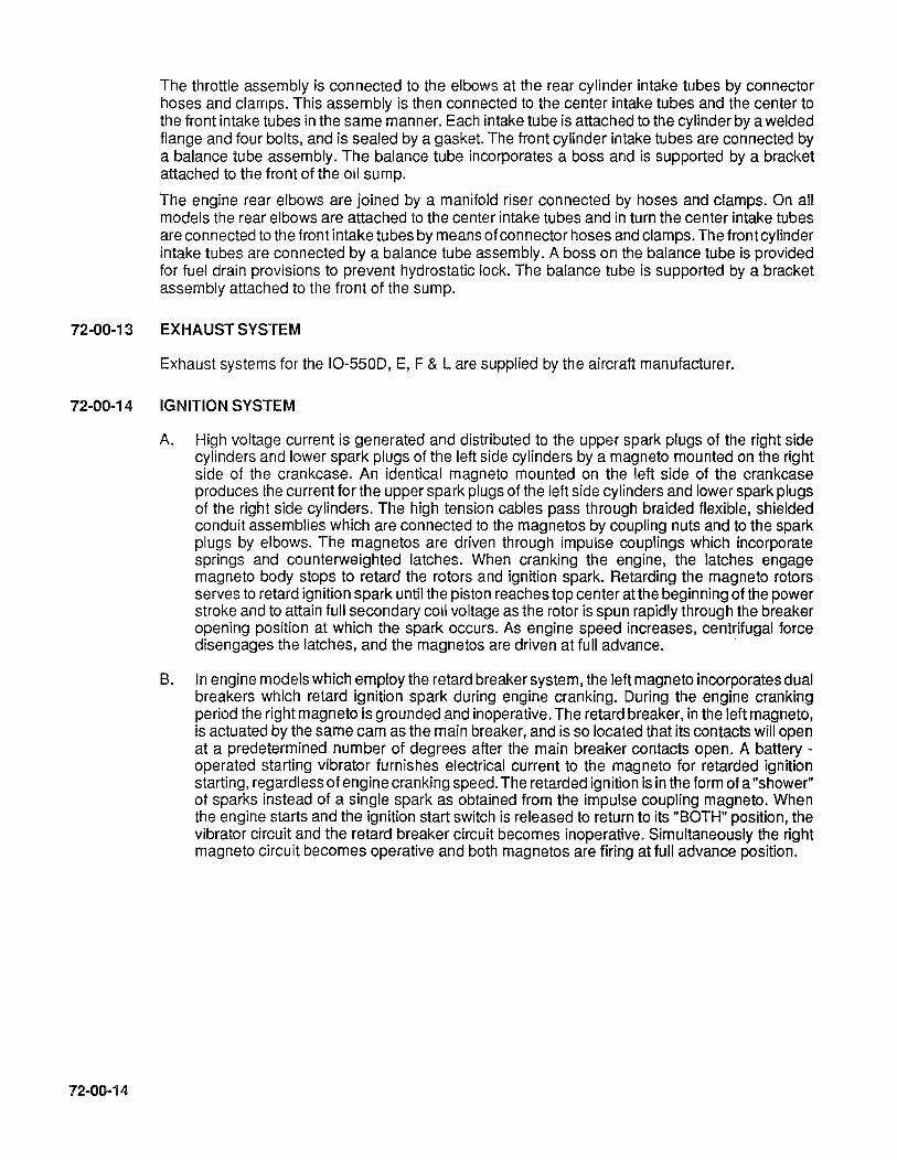
The throttle assembly is connected to the elbows at the rear cylinder intake tubes by connector hoses and clamps. This assembly is then connected to the center intake tubes and the center to the front intake tubes in the same manner. Each intake tube is attached to the cylinder by a welded flange and four bolts, and is sealed by a gasket. The front cylinder intake tubes are connected by a balance tube assembly. The balance tube incorporates a boss and is supported by a bracket attached to the front of the oil sump.
The engine rear elbows are joined by a manifold riser connected by hoses and clamps. On all models the rear elbows are attached to the center intake tubes and in turn the center intake tubes are connected to the front intake tubes by means of connector hoses and clamps. The front cylinder intake tubes are connected by a balance tube assembly. A boss on the balance tube is provided for fuel drain provisions to prevent hydrostatic lock. The balance tube is supported by a bracket assembly attached to the front of the sump.
72-00-13 EXHAUST SYSTEM
Exhaust systems for the 10-5500, E, F & L are supplied by the aircraft manufacturer.
72-00-14 IGNITION SYSTEM
72-00-14
A. High voltage current is generated and distributed to the upper spark plugs of the right side cylinders and lower spark plugs of the left side cylinders by a magneto mounted on the right side of the crankcase. An identical magneto mounted on the left side of the crankcase produces the current for the upper spark plugs of the left side cylinders and lower spark plugs of the right side cylinders. The high tension cables pass through braided flexible, shielded conduit assemblies which are connected to the magnetos by coupling nuts and to the spark plugs by elbows. The magnetos are driven through impulse couplings which incorporate springs and counterweighted latches. When cranking the engine, the latches engage magneto body stops to retard the rotors and ignition spark. Retarding the magneto rotors serves to retard ignition spark until the piston reaches top center atthe beginning ofthe power stroke and to attain full secondary coil voltage as the rotor is spun rapidly through the breaker opening position at which the spark occurs. As engine speed increases, centrifugal force disengages the latches, and the magnetos are driven at full advance. .
B. In engine models which employ the retard breaker system, the left magneto incorporates dual breakers which retard ignition spark during engine cranking. During the engine cranking period the right magneto is grounded and inoperative. The retard breaker, in the left magneto, is actuated by the same cam as the main breaker, and is so located that its contacts will open at a predetermined number of degrees after the main breaker contacts open. A battery -operated starting vibrator furnishes electrical current to the magneto for retarded ignition starting, regardless of engine cranking speed. The retarded ignition is in the form of a "shower" of sparks instead of a single spark as obtained from the impulse coupling magneto. When the engine starts and the ignition start switch is released to return to its "BOTH" position, the vibrator circuit and the retard breaker circuit becomes inoperative. Simultaneously the right magneto circuit becomes operative and both magnetos are firing at full advance position.
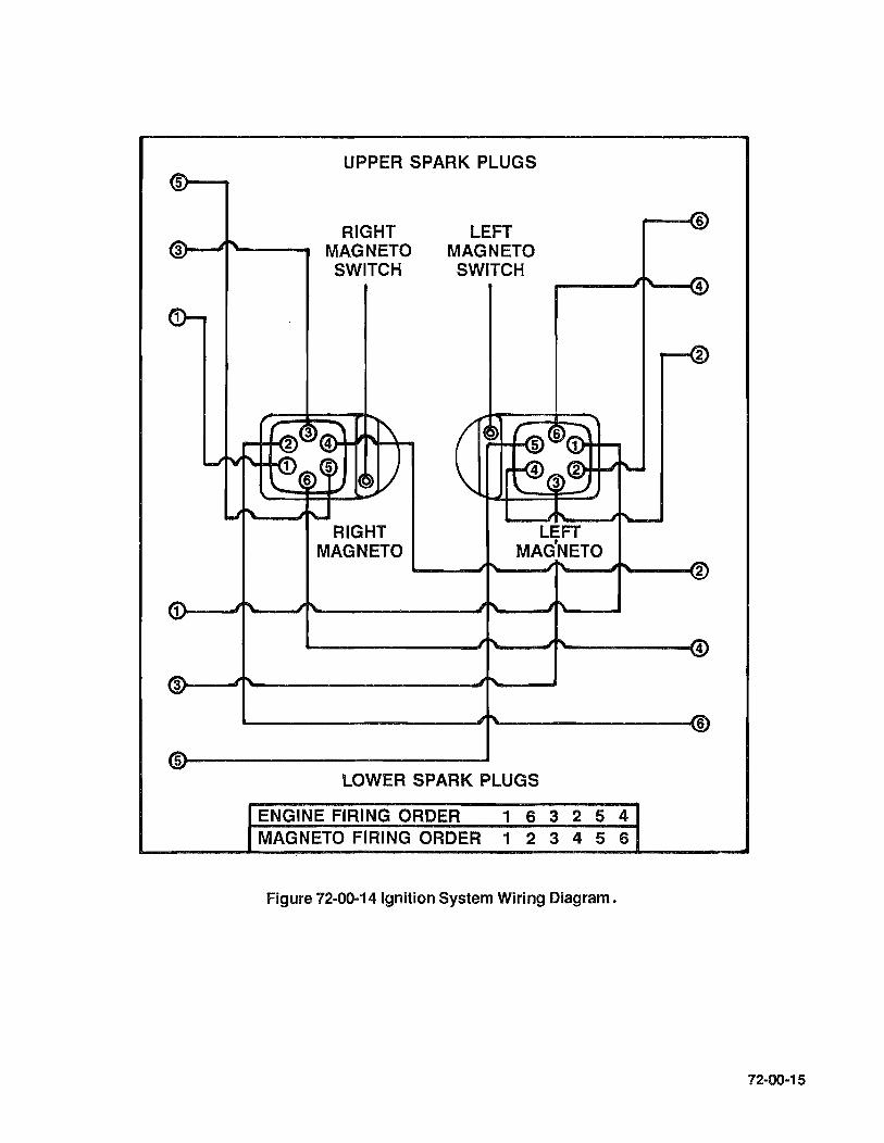
5>---UPPER SPARK PLUGS
RIGHT MAGNETO SWITCH
RIGHT MAGNETO
LEFT MAGNETO SWITCH
---- --- ""--"If'----f2
'-------- --- ""'------{4
~-----------------J~------------~6
5r-----------------------~ LOWER SPARK PLUGS
ENGINE FIRING ORDER 1 6 3 2 5 4 MAGNETO FIRING ORDER 1 2 3 4 5 6
Figure 72-00-14 Ignition System Wiring Diagram.
72-00-15

72-00-16
INTENTIONALL Y
LEFT
BLANK

SECTION 72-10 DISASSEMBL Y
72-10-00 General 72-10-01 Engine Removal Instructions 72-10-02 Extent of Disassembly 72-10-03 Parts to be Discarded 72-10-04 Preliminary Cleaning 72-10-05 Ignition System 72-10-06 Fuel Injection System 72-10-07 Magneto and Accessory Drives 72-10-08 Induction System 72-10-09 Oil Sump 72-10-10 Oil Cooler 72-10-11 Alternator Assembly 72-10-12 Starter and Starter Drive Adapter 72-10-13 Oil Pump Assembly 72-10-14 Cylinders and Pistons 72-10-15 Crankcase 72-10-16 Camshaft Assembly 72-10-17 Crankshaft Group 72-10-18 Exhaust System
72-10-01

72-10-02
INTENTIONALLY
LEFT
BLANK

72-10-00 GENERAL
72-10-01
Instructions in this section are based on the assumption that all parts attached by the aircraft manufacturer, except optional pumps have been removed.
Accessories supplied by the engine manufacturer may be serviced according to instructions supplied by the applicable accessory manufacturer.
ENGINE REMOVAL INSTRUCTIONS
Properly identify each part by marking or tagging as it is disconnected from the engine, to aid in reinstallation.
NOTE ... lf the engine is being removed to be placed in storage, accomplish steps listed in Section 72-80-03, "Indefinite Storage", prior to removal.
1. Turn all cockpit switches and fuel selector valves OFF.
2. Drain the engine oil from the sump. Replace drain plug and tighten.
3. Disconnect the battery ground cable.
4. Disconnect the starter cable.
5. Tag and disconnect the engine wiring bundle from the following components.
a. Magnetos
b. Alternator
c. Tach Generator
d. Oil Temperature Bulb
e. Cylinder Head Temperature Bulb
f. Remove all clamps attaching engine wire bundle to engine components and route clear of the engine.
6. Disconnect propeller, throttle, and mixture control cables.
7. Disconnect fuel, manifold pressure and oil hoses from engine.
8. Remove exhaust system.
9. Remove the propeller in accordance with airframe manufacturer's instructions.
10. Remove engine to airframe connections in accordance with airframe manufacturer's instructions.
Attach a hoist to the engine lifting eye and relieve the weight from the engine mounts.
CAUTION ... Place a suitable stand under the aircraft tail section load bearing area (jack pad or NC tie down eye) before removing the engine. The loss of weight may cause the tail to drop.
72-10-03

11. Remove the engine mounts.
12. Hoist engine vertically out of the nacelle and clear of the aircraft.
NOTE ... Hoist engine slowly, making sure that all wires, lines and hoses have been disconnected.
13. Install engine on a transportation stand, dolly, or on the engine shipping container base.
72-10-02 EXTENT OF DISASSEMBLY. Line drawings reproduced in this section are similar to those used in the parts catalog. The location of components and attaching parts in the illustrations will be sufficient to enable personnel to accomplish disassembly operations.
72-10-03 PARTS TO BE DISCARDED. Discard all shakeproof washers, lockwires, tab washers, rubber seal rings, oil seals, gaskets, cotter pins, flex hoses, hose connectors and magneto coupling (rubber) bushings in such a manner that they will not be used again inadvertently. Care should be taken in removing gaskets from aluminum parts by scraping. Such removal should be delayed until the part is to be cleaned. Refer to TCM Section 1-00-04 and Service Bulletin MS7-11 R2 "Overhaul 1 00% Replacement Parts," or current revision as applicable.
72-10-04 PRELIMINARY CLEANING. Spray or brush with a solvent used for general cleaning of engine parts. Remove caked dirt on bolt heads and nuts especially. At the same time the oil sump drain plugs should be removed to drain any remaining oil.
CAUTION ... Do not use caustic cleaning solutions for external pre cleaning, these solutions will remove the "alodized" finish of aluminum parts.
72-10-0SA IGNITION SYSTEM 10-SSO-D,E & L. (See Figure 72-1 O-OSA).
72·10-04
A. Remove four sets of attaching parts (7, 6) and cable outlet plate (23) from each magneto (2).
B. Remove outlet plate grommets (24) and cable outlet plate (23) from ignition cables (9 thru 20). Remove ignition leads from spark plugs (S).
C. Remove clamps (2S) by removing attaching parts (27, 29). Remove attaching screw (30) and remove clamp, bracket (31). Cut and remove cable ties (32). Remove clamps (25, 26).
D. Remove ignition harness assembly from engine and discard.
E. Remove two sets of attaching parts (3, 4, 5), magnetos (2) and gaskets (1). Discard gaskets (1 ).
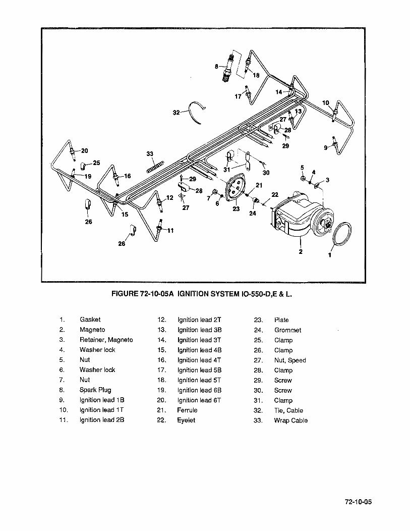
32~
iPts~ i-29 .~31 ~ 30
o 21
~28 7~ • 22 27 6 r-.(
23 24
~3 I
26
ft 26
2 1
FIGURE 72-10-05A IGNITION SYSTEM IO-550-D,E & L.
1. Gasket 12. Ignition lead 2T 23. Plate
2. Magneto 13. Ignition lead 3B 24. Grommet
3. Retainer, Magneto 14. Ignition lead 3T 25. Clamp
4. Washer lock 15. Ignition lead 4B 26. Clamp
5. Nut 16. Ignition lead 4T 27. Nut, Speed
6. Washer lock 17. Ignition lead 5B 28. Clamp
7. Nut 18. Ignition lead 5T 29. Screw
8. Spark Plug 19. Ignition lead 6B 30. Screw
9. Ignition lead 1 B 20. Ignition lead 6T 31. Clamp
10. Ignition lead iT 21. Ferrule 32. Tie, Cable
11. Ignition lead 2B 22. Eyelet 33. Wrap Cable
72-10-05

72-10-058 IGNITION SYSTEM IO-SSO-F. (See Figure 72-10-0S8)~
72-10-06
A. Remove four sets of attaching parts (23,24) and cable outlet plate (21) from each magneto (2).
B. Remove outlet plate grommets (22) and cable outlet plate (21) from ignition cables (7 thru 18). Remove ignition leads from spark plugs (6).
C. Remove clamps (28) by removing attaching parts (27, 29). Remove attaching screw (30) and remove clamp, bracket (31). Cut and remove cable ties (32). Remove Clamps (25, 26).
D. Remove ignition harness assembly from engine and discard.
E. Disconnect Retard and Ground terminal kits (34, 35) from magnetos (2).
F. Remove two sets of attaching parts (3,4,5), magnetos (2) and gaskets (1). Discard gaskets (1 ).

FIGURE 72-10-058 IGNITION SYSTEM IO-SSO-F.
1. Gasket 13. Ignition lead 48 25. Clamp
2. Magneto 14. Ignition lead 4T 26. Clamp
3. Retainer, Magneto 15. Ignition lead 58 27. Nut, Speed
4. Washer lock 16. Ignition lead 5T 28. Clamp
5. Nut 17. Ignition lead 68 29. Screw
6. Spark Plug 18. Ignition lead 6T 30. Screw
7. Ignition lead 18 19. Ferrule 31. Clamp
8. Ignition lead 1T 20. Eyelet 32. Tie, Cable
9. Ignition lead 28 21. Plate 33. Wrap Cable
10. Ignition lead 2T 22. Grommet 34. Kit Ground Terminal
11. Ignition lead 38 23. Washer, Lock 35. Kit Retard Terminal
12. Ignition lead 3T 24. Screw
72-10-07
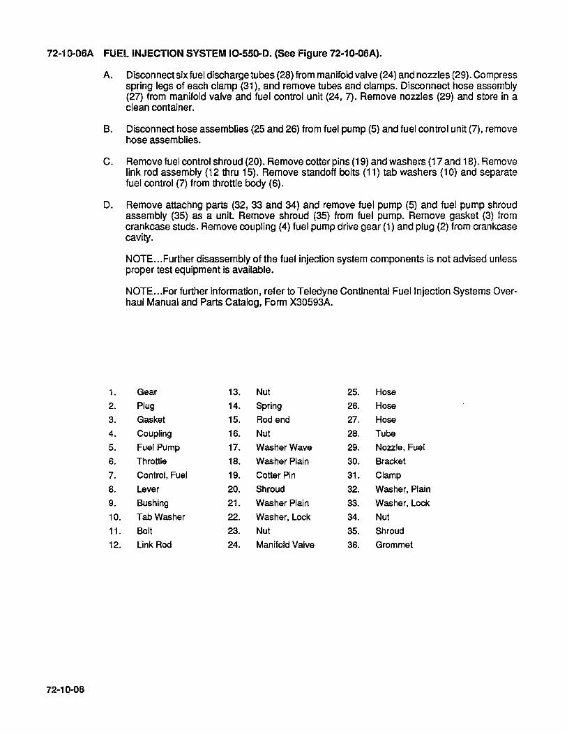
72-10-06A FUEL INJECTION SYSTEM 10-550-D. (See Figure 72-10-06A).
72-10-08
A. Disconnect six fuel discharge tubes (28) from manifold valve (24) and nozzles (29). Compress spring legs of each clamp (31), and remove tubes and clamps. Disconnect hose assembly (27) from manifold valve and fuel control unit (24, 7). Remove nozzles (29) and store in a clean container.
B. Disconnect hose assemblies (25 and 26) from fuel pump (5) and fuel control unit (7), remove hose assemblies.
C. Remove fuel control shroud (20). Remove cotter pins (19) and washers (17 and 18). Remove link rod assembly (12 thru 15). Remove standoff bolts (11) tab washers (10) and separate fuel control (7) from throttle body (6).
D. Remove attachng parts (32, 33 and 34) and remove fuel pump (5) and fuel pump shroud assembly (35) as a unit. Remove shroud (35) from fuel pump. Remove gasket (3) from crankcase studs. Remove coupling (4) fuel pump drive gear (1) and plug (2) from crankcase cavity.
1.
2.
3.
4.
5.
6.
7.
8.
9.
10.
11.
12.
NOTE ... Further disassembly of the fuel injection system components is not advised unless proper test equipment is available.
NOTE ... For further information, refer to Teledyne Continental Fuel Injection Systems Overhaul Manual and Parts Catalog, Form X30593A.
Gear 13. Nut 25. Hose
Plug 14. Spring 26. Hose
Gasket 15. Rod end 27. Hose
Coupling 16. Nut 28. Tube
Fuel Pump 17. Washer Wave 29. Nozzle, Fuel
Throttle 18. Washer Plain 30. Bracket
Control, Fuel 19. Cotter Pin 31. Clamp
Lever 20. Shroud 32. Washer, Plain
Bushing 21. Washer Plain 33. Washer, Lock
Tab Washer 22. Washer, Lock 34. Nut
Bolt 23. Nut 35. Shroud
Link Rod 24. Manifold Valve 36. Grommet

28
27
19~ /' 18
17~~ . 13
12 ,,---1 14
(1; /15 . ~~~ ,
25 16
A FUEL INJECTION SY FIGURE 72-10-06 STEM (IO-550-D).
6 26
72-10-09
72-10-068 FUEL INJECTION SYSTEM, IO-SSO-E. (See Figure 72-10-068).
72-10-10
A. Disconnect six fuel discharge tubes (29) from manifold valve (25) and nozzles (30). Compress spring legs of each clamp (32), and remove tubes and clamps. Disconnect hose assembly (28) from manifold valve and fuel control unit (7). Remove nozzles (30) and store in a clean container.
B. Disconnect hose assemblies (26 and 27) from fuel pump (5) and fuel control unit (7), remove hose assemblies.
C. Remove fuel control shroud (20). Remove cotter pins (19) and washers (17 and 18). Remove link rod assembly (12 thru 16). Remove standoff bolts (11), tab washers (10) and separate fuel control from throttle body (6).
D. Remove attaching parts (33, 34, 35) and remove fuel pump (5) and fuel pump shroud assembly (37) as a unit. Remove shroud (37) from fuel pump. Remove gasket (3) from crankcase studs. Remove coupling (4) fuel pump drive gear (1) and plug (2) from crankcase cavity.
NOTE ... Further disassembly of the fuel injection system components is not advised unless proper test equipment is available.
NOTE. .. For further information, refer to Teledyne Continental Fuel Injection Systems Overhaul Manual and Parts Catalog, Form X30593A.

1
2.
3.
4.
5.
6.
7.
8.
9.
10.
11.
12.
, ~ '~. J
Qifh . .I
, -,')
10 . 21 11 / ~~I
20 21/ /"'f 24 22/}_
, 23
27
I
/
J FIGURE 72-10-068 FUEL INJECTION SYSTEM (IO-550-E).
Gear, Drive 13. Nut 25. Valve, Manifold
Plug 14. Spring 26. Hose Assy., Fuel
Gasket 15. Rod End 27. Hose Assy., Fuel
Coupling 16. Nut 28. Hose Assy., Fuel
Fuel Pump 17. Washer, Wave 29. Tube Assy.
Throttle 18. Washer, Plain 30. Nozzle, Fuel
Fuel Control 19. Pin, Cotter 31. Bracket
Lever 20. Shroud ,Fuel Control 32. Clamp
Bushing 21. Washer, Plain 33. Washer, Plain
Tab, Washer 22. Washer, lock 34. Washer, Lock
Bolt, Standoff 23. Nut 35. Nut
Rod and Link Assy. 24. Bolt 36. Grommet
37. Shroud, Fuel Pump
72-10-11

72-10-06C FUEL INJECTION SYSTEM, IO-550-F & L. (See Figure 72-10-06C).
72-10-12
A. Disconnect six fuel discharge tubes (28) from manifold valve (24) and nozzles (29). Compress spring legs of each clamp (31), and remove tubes and clamps. Disconnect hose assembly (27) from manifold valve and fuel control unit (7). Remove nozzles (29) and store in a clean container.
B. Disconnect hose assemblies (25, 26 and 27) from fuel pump (5) and fuel control unit (7), remove hose assemblies.
C. Remove fuel control shroud (20). Remove cotter pins (19) and washers (17 and 18). Remove link rod assembly (13). Remove standoff bolts (12), tab washers (11) and separate fuel control from throttle body (6).
D. Remove attaching parts (32,33 and 34) and remove fuel pump (5) and fuel pump shroud assembly (36) as a unit. Remove shroud (36) from fuel pump. Remove gasket (3) from crankcase studs. Remove coupling (4) fuel pump drive gear (1) and plug (2) from crankcase cavity.
NOTE ... Further disassembly of the fuel injection system components is not advised unless proper test equipment is available.
NOTE ... For further information, refer to Teledyne Continental Fuel Injection Systems Overhaul Manual and Parts Catalog, Form X30593A.

r' .,~
28 24~~ . I 27 •
I
)
FIGURE 72·10-06C FUEL INJECTION SYSTEM (IO-550-F & L).
1. Gear, Drive 13. Rod and Link Assy. 25. Hose, Fuel 2. Plug 14. Spring 26. Hose, Fuel 3. Gasket 15. Rod End 27. Hose, Fuel 4. Coupling 16. Nut 28. Tube, Assy. 5. Fuel Pump 17. Washer, Wave 29. Nozzle 6. Throttle 18. Washer, Plain 30. Bracket 7. Fuel control 19. Pin, Cotter 31. Clamp 8. Lever 20. Shroud Fuel, Control 32. Washer, Plain 9. Bushing 21. Washer. Plain 33. Washer, Lock 10. Pin 22. Washer, Lock 34. Nut 11. Washer, Tab 23. Nut 35. Grommet 12. Bolt, standoff 24. Valve, Manifold 36. Shroud, Fuel Pump
72-10-13
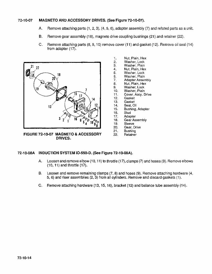
72-10-07 MAGNETO AND ACCESSORY DRIVES. (See Figure 72-10-07).
21
A. Remove attaching parts (1, 2, 3), (4,5, 6), adapter assembly (7) and related parts as a unit.
B. Remove gear assembly (18), magneto drive coupling bushings (21) and retainer (22).
C. Remove attaching parts (8, 9,10) remove cover (11) and gasket (12). Remove oil seal (14) from adapter (17).
1. Nut, Plain, Hex 2. Washer, Lock 3. Washer, Plain 4. Nut, Plain, Hex 5. Washer,Lock 6. Washer, Plain 7. Adapter Assembly 8. Nut, Plain, Hex 9. Washer, Lock 10. Washer, Plain 11. Cover, Accy. Drive 12. Gasket 13. Gasket 14. Seal, Oil 15. Bushing, Adapter 16. Stud 17. Adapter 18. Gear Assembly 19. Sleeve 20. Gear, Drive
FIGURE 72-10-07 MAGNETO & ACCESSORY DRIVES.
21. Bushing 22. Retainer
72-10-0SA INDUCTION SYSTEM 10-550-0. (See Figure 72-10-0SA).
72-10-14
A. Loosen and remove elbow (1 0, 11) to throttle (17), clamps (7) and hoses (9). Remove elbows (10, 11) and throttle (17).
B. Loosen and remove remaining clamps (7,8) and hoses (9). Remove attaching hardware (4, 5, 6) and riser assemblies (2, 3) from all cylinders. Remove and discard gaskets (1).
C. Remove attaching hardware (13, 15, 16), bracket (12) and balance tube assembly (14).
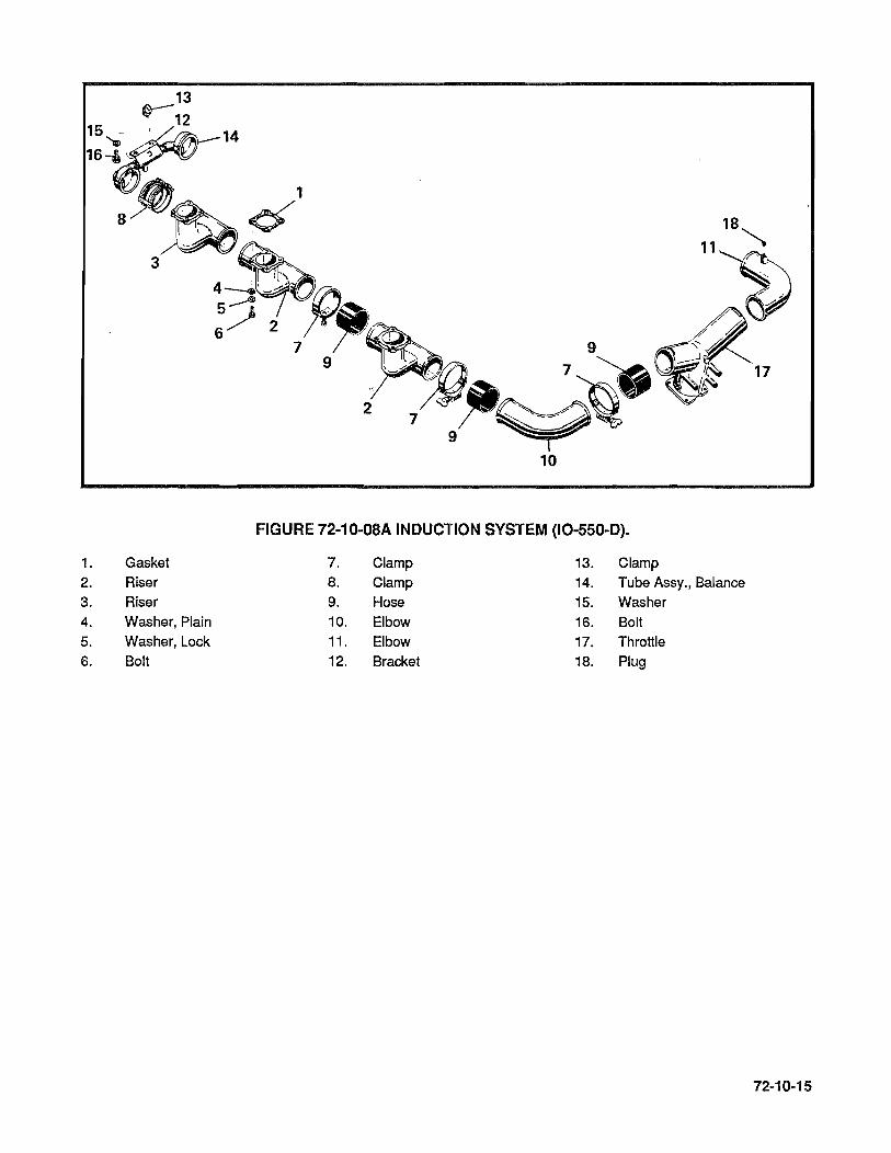
10
FIGURE 72-10-0SA INDUCTION SYSTEM (IO-SSO-D).
1. Gasket 7. Clamp 13. Clamp 2. Riser 8. Clamp 14. Tube Assy., Balance
3. Riser 9. Hose 15. Washer 4. Washer, Plain 10. Elbow 16. Bolt 5. Washer, Lock 11. Elbow 17. Throttle 6. Bolt 12. Bracket 18. Plug
72-10-15
72-10-088 INDUCTION SYSTEM IO-550-E. (See Figure 72-10-088).
72·10-16
A. Remove attaching hardware (33,34,35), loosen and remove attaching hardware (20,21), remove airframe supplied attaching hardware and separate brackets (22,23) from throttle (37). Loosen elbow (12,13), clamps and hoses (7,10). Remove throttle assembly (37).
B. Remove attaching hardware (29,30) and brackets (25,32). Separate brackets (25,32) by removing attaching hardware (26,27 & 28).
C. Loosen clamp (15), remove attaching hardware (17,18) and bracket (16). Loosen clamp assemblies (9) and remove balance tube (14).
D. Remove three sets of attaching hardware (4,5,6) and remove 1-3-5 bank of induction risers (2,3) as one unit. Remove three sets of attaching hardware (4,5,6) and remove 2-4-6 risers (2,3) in the same manner.
E. Loosen clamps (7,8) and separate risers (2,3). Discard hoses (10). Remove and discard gaskets (1).

1 .
2. 3. 4. 5. 6. 7. 8.
9. 10.
11.
12. 13.
6 5 4
t'>-1 ,
7
13
FIGURE 72-1 0-08B. INDUCTION SYSTEM (IO-550-E).
Gasket 14. Tube, Assembly Balance 27. Washer, Lock
Tube, Intake Manifold 15. Clamp 28. Nut, Plain Tube, Intake Manifold 16. Bracket, Balance Tube 29. Screw Bolt 17. Screw
Washer, Lock 18. Washer, Lock 30. Washer, Lock
Washer, Plain 19. Bracket, Air Throttle 31. Washer, Plain
Clamp, Hose 20. Bolt 32. Bracket
Clamp, Hose 21. Nut, Self Locking 33. Nut, Plain Clamp Assembly Hose 22. Bracket UH 34. Washer, Lock Hose, Intake Manifold 23. Bracket RlH
Tube, Elbow 24. Bushing 35. Washer, Plain
Tube, Elbow 25. Bracket 36. Gasket
Plug 26. Screw 37. Throttle Assembly
72-10-17

72-10-08C INDUCTION SYSTEM IO-550-F & L (See Figure 72-10-08C).
72-10-18
A. Remove attaching hardware (26,27),(29,30) and bracket (25). Remove attaching hardware (20,21,23,24). Loosen and remove elbows (11 ,12) to throttle (19). Loosen and remove clamps (7) and hoses (10). Remove elbows (11) and throttle (19). Separate bracket (22) from crankcase, remove attaching hardware (30 thru 33) and brackets (28).
B. Loosen and remove remaining clamps (7,8,9) and hoses (10). Remove attaching hardware (4,5,6) and risers (2,3). Remove and discard gaskets (1).
C. Remove attaching hardware (17,18), clamp (15), bracket (14) and balance tube assembly (16).

11 7
FIGURE 72-10-08C INDUCTION SYSTEM (IO-550-F & L).
1. Gasket 13. Plug 25. Bracket
2. Riser 14. Bracket 26. Washer 3. Riser 15. Clamp
27. Nut 4. Washer, Plain 16. Balance Tube
5. Washer, Lock 17. Washer, Lock 28. Bracket
6. Bolt 18. Bolt 29. Bolt
7. Clamp 19. Throttle 30. Nut 8. Clamp 20. Bushing 31. Washer, Lock 9. Clamp 21. Sleeve
10. Hose 22. Bracket 32. Washer
11. Elbow 23. Bolt 33. Bolt
12. Elbow 24. Nut 34. Gasket
72-10-19
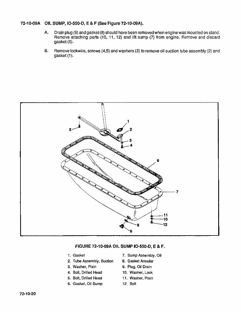
72-10-09A OIL SUMP, 10-550-0, E & F (See Figure 72-10-09A).
72-10-20
A. Drain plug (9) and gasket (8) should have been removed when engine was mounted on stand. Remove attaching parts (10, 11, 12) and lift sump (7) from engine. Remove and discard gasket (6).
B. Remove lockwire, screws (4,5) and washers (3) to remove oil suction tube assembly (2) and gasket (1).
'r---7
FIGURE 72-10-09A OIL SUMP 10-550-0, E & F.
1. Gasket 7. Sump Assembly, Oil
2. Tube Assembly, Suction 8. Gasket Annular
3. Washer, Plain 9. Plug, Oil Drain
4. Bolt, Drilled Head 10. Washer, Lock
5. Bolt, Drilled Head 11. Washer, Plain
6. Gasket, Oil Sump 12. Bolt

72-10-098 OIL SUMP, IO·550-L (See Figure 72-10-098).
A. Drain plug (12) and gasket (11) should have been removed when engine was mounted on stand.
B. Remove attachng parts (8,9,10) and lift off sump (7). Remove and discard gasket (6).
C. Remove lockwire, screws (4,5,), washers (3) and remove oil suction tube assembly (2). Remove and discard gasket (1).
o 0
o~ o
o
*646942 Gasket Maker
o
o
~8 ®--9
~10
FIGURE 72·10-098 OIL SUMP (IO-550-L).
1. Gasket, Suction Tube 7. Sump Assembly, Oil
2. Tube Assembly, Suction 8. Washer, Plain
3. Washer, Plain 9. Washer, Lock
4. Bolt, Drilled Head 10. Bolt
5. Bolt, Drilled Head 11. Gasket Annular
6. Gasket, Oil Sump 12. Plug, Oil Drain
6
72-10-21
72-10-10 OIL COOLER 10-550-D, E & F (See Figure 72-10-10).
72-10-22
A. Remove attachng parts (3,4,5) and separate oil cooler (1) and gasket (2) from adapter (6).
B. Remove attaching parts (10,11,12) and pull adapter (6) and gasket (7) from crankcase by gently tapping with a soft leather or rubber mallet.
C. Remove oil temperature control valve (13) and gasket (14) from adapter.
OIL COOLER 10-550-L (See Figure 72-10-10).
A. The IO-550-L utilizes and adapter (8) to provide connections for an external airframe mounted oil cooler.
B. Remove fittings, hoses, attaching hardware (10,11,12) and adapter (8). Remove and discard gasket (9).

FIGURE 72-10-10 OIL COOLER ASSEMBLY.
1. Cooler, Oil 9. Gasket <D 2. Gasket· 10. Washer, Plain
3. Bolt 11. Washer, Lock
4. Washer, Lock 12. Nut
5. Washer, Plain 13. Valve, Oil Temperature
Control
6. Plate, Oil Cooler 14. a-Ring
7. Gasket 15. Nipple, Flared <D 8. Adapter <D 16. Elbow, 90· <D
G) IO-550-L ONL Y.
72-10-23

72-10-11 ALTERNATOR ASSEMBLY IO-550-E & F (See Figure 72-10-11).
72-10-24
A. Before loosening alternator attaching hardware, loosen sheave retaining nut (3).
B. Remove attaching hardware (10 thru 15) and adjusting bracket (10). Loosen nut (5) and bolt (8), push alternator (1) inward and remove drive belt (16).
C. Remove nut (5), bolt (8), washers (6,7) and alternator (1).
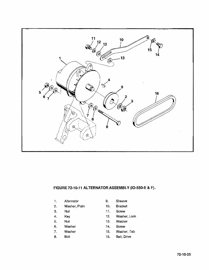
1~ 14
1
9
16
FIGURE 72-10-11 ALTERNATOR ASSEMBLY (IO-550-E & F).
1. Alternator 9. Sheave
2. Washer, Plain 10. Bracket
3. Nut 11. Screw
4. Key 12. Washer, Lock
5. Nut 13. Washer
6. Washer 14. Screw
7. Washer 15. Washer, Tab
8. Bolt 16. Belt, Drive
72-10-25
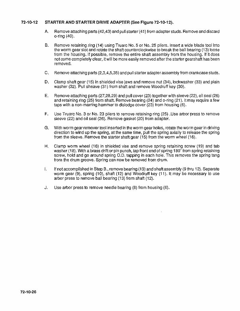
72-10-12 STARTER AND STARTER DRIVE ADAPTER (See Figure 72-10-12).
72-10·26
A. Remove attaching parts (42,43) and pull starter (41) from adapter studs. Remove and discard o-ring (40).
s. Remove retaining ring (14) using Truarc No.5 or No. 25 pliers. Insert a wide blade tool into the worm gear slot and rotate the shaft counterclockwise to break the ball bearing (13) loose from the housing. If possible, remove the entire shaft assembly from the housing. If it does not come completely clear, it will be more easily removed after the starter gearshaft has been removed.
C. Remove attaching parts (2,3,4,5,35) and pull starter adapter assembly from crankcase studs.
D. Clamp shaft gear (15) in shielded vise jaws and remove nut (34), lockwasher (33) and plain washer (32). Pull sheave (31) from shaft and remove Woodruff key (30).
E. Remove attaching parts (27,28,29) and pull cover (23) together with sleeve (22), oil seal (26) and retaining ring (25) from shaft. Remove bearing (24) and o-ring (21). It may require a few taps with a non-marring hammer to dislodge cover (23) from housing (6).
F. Use Truarc No.3 or No. 23 pliers to remove retaining ring (25) .Use arbor press to remove sleeve (22) and oil seal (26). Remove gasket (20) from adapter.
G. With worm gear remover tool inserted in the worm gear holes, rotate the worm gear in driving direction to wind up the spring, at the same time, pull the spring axially to release the spring from the sleeve. Remove the starter shaft gear (15) from the worm wheel (16).
H. Clamp worm wheel (16) in shielded vise and remove spring retaining screw (19) and tab washer (18). With a brass drift or pin punch, tap front end of spring 180· from spring retaining screw, hold and go around spring O.D. tapping in each hole. This removes the spring tang from the drum groove. Spring can now be removed from drum.
I. If not accomplished in Step S., remove bearing (13) and shaft assembly (9 thru 12). Separate worm gear (9), spring (10), shaft (12) and Woodruff key (11). It may be necessary to use arbor press to remove ball bearing (13) from shaft (12).
J. Use arbor press to remove needle bearing (8) from housing (6).
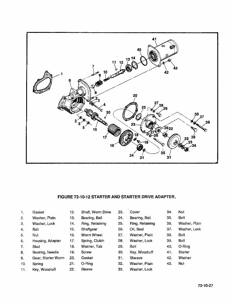
FIGURE 72·10·12 STARTER AND STARTER DRIVE ADAPTER.
1. Gasket 12. Shaft, Worm Drive 23. Cover 34. Nut
2. Washer, Plain 13. Bearing, Ball 24. Bearing, Ball 35. Bolt
3. Washer, Lock 14. Ring, Retaining 25. Ring, Retaining 36. Washer, Plain
4. Bolt 15. Shaftgear 26. Oil,Seal 37. Washer, Lock
5. Nut 16. Worm Wheel 27. Washer, Plain 38. Bolt
6. Housing, Adapter 17. Spring, Clutch 28. Washer, Lock 39. Bolt
7. Stud 18. Washer, Tab 29. Bolt 40. O-Ring
8. Bearing, Needle 19. Screw 30. Key, Woodruff 41. Starter
9. Gear, Starter Worm 20. Gasket 31. Sheave 42. Washer
10. Spring 21. O-Ring 32. Washer, Plain 43. Nut
11. Key, Woodruff 22. Sleeve 33. Washer, Lock
72·10-27

72-10-13A OIL PUMP, 10-550-0 & F (See Figure 72-10-13A).
72-10-28
A. Loosen oil screen (26) and tachometer drive housing (23), to facilitate later removal. (Tachometer drive housing has a left-handed thread). Remove attaching parts (37,38,39) and pull pump assembly to the rear. Remove and discard gasket (1).
B. Remove oil screen (26) and gasket (25).
C. Remove remaining attaching parts (37,38,39) and separate cover (20) from pump housing (2). Remove tachometer drive housing (23). Press oil seal (24) from housing. Remove gasket (22) and tachometer drive shaft (21).
D. Remove oil pump drive gear assembly and separate tachometer drive gear (19), oil pump drive gear (17) and pin (18). Remove oil pump driven gear and bushing assembly (6,7).
E. Remove oil pressure relief valve (9 thru 16). Remove by-pass assembly (33 thru 36).
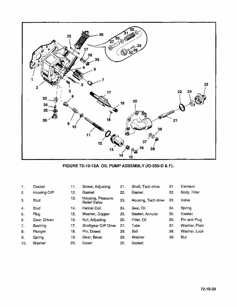
7 23
I 5
33 l 8
34 19 20
35
36 9
10
18 ?~\\ (~ ~
38
~ 3l~ 13 ;JI; ~ 16 39
14 15
12
FIGURE 72-10-13A OIL PUMP ASSEMBLY (10-550-D & F).
1. Gasket 11. Screw, Adjusting 21. Shaft, Tach drive 31. Element
2. Housing OIP 12. Gasket 22. Gasket 32. Body, Filter
3. Stud 13. Housing, Pressure 23. Housing, Tach drive 33. Valve Relief Valve
4. Stud 14. Helical Coil 24. Seal,Oil 34. Spring
5. Plug 15. Washer, Copper 25. Gasket, Annular 35. Gasket
6. Gear, Driven 16. Nut, Adjusting 26. Filter, Oil 36. Pin and Plug
7. Bushing 17. Shaftgear OIP Drive 27. Tube 37. Washer, Plain
8. Plunger 18. Pin, Dowel 28. Bolt 38. Washer, Lock
9. Spring 19. Gear, Bevel 29. Washer 39. Nut
10. Washer 20. Cover 30. Gasket
72·10·29

72-10-138 Oil PUMP IO-550-E & l (See Figure 72-10-138).
72-10-30
A. Loosen oil filter (44) and tachometer drive housing (23) or covers 32,27 as applicable to facilitate later removal. (Tachometer drive housing has a left hand-thread) Remove attaching parts (41 ,42,43) and pull pump assembly to the rear clear of crankcase. Remove and discard gasket (1).
B. Remove oil filter (44).
C Remove remaining attaching parts (41,42,43) and separate cover (22) or (27) as applicable from pump housing (2). On IO-550-E, remove tachometer drive housing (23). Press oil seal (24) from housing. Remove gasket (26) and tachometer drive shaft (25). On IO-550-L, remove covers (32,37), tachometer drive gear (30) and press oil seal (28) from cover (27).
D. Remove oil pump drive gear assembly and separate tachometer drive gear (21), oil pump drive gear (19) and pin (20). Remove oil pump driven gear and bushing asssembly (8,9).
E. Remove oil pressure relief valve (10 thru 18). Remove plug (7).

2
1
IO--SSO--L
I
1\ 14
FIGURE 72-10-13B Oil PUMP ASSEMBLY (IO-550-E & l).
1. Gasket 13. Screw Adjusting 23. Housing Tach 35. Screw
2. Housing, OIP 14. Gasket Drive 36. Gasket
3. Stud 15. Housing, Pressure 24. Seal
4. Stud Relief Valve 25. Shaft, Tach Drive 37. Cover
5. Stud 16. Helical Coil 26. Gasket 38. Washer, Plain
6. Plug 17. Washer, Copper 27. Cover,OIP 39. Washer, Lock
7. Plug 18. Nut, Adjusting 28. Seal,Oil
8. Gear, Driven Screw 29. Stud 40. Nut
9. Bushing 19. Shaftgear OIP 30. Gear Bevel 41. Washer, Plain
10. Plunger, Pressure Drive 31. Gasket 42. Washer, Lock
Relief Valve 20. Pin, Dowel 32. Cover
11. Spring 21. Gear, Bevel 33. Washer, Plain 43. Nut
12. Seat 22. Cover 34. Washer, Lock 44. Filter, Oil
72-10-31

72-10-14 CYLINDER AND PISTON ASSEMBLY (See Figure 72-1 0-14).
72·10·32
A. Remove attaching parts (30,31,32), cover (29) and gasket (28).
B. Position crankshaft so valve lifters of cylinders to be removed, are on base circle of cam lobes and both valves are fully closed. Remove screw (27), washer (26), shafts (25), rocker assembiles (19 thru 23) and thrust washers (24). Withdraw pushrods (39). Repeat these steps on remaining cylinders.
C. Push the pushrod housing (35) against the spring (38) until the cylinder flange end is clear. Lift cylinder end of housing and withdraw from crankcase. Remove spring (38), washers (36) and packing (37).
D. Remove one flanged nut (41), and three flanged nuts (40) from each cylinder flange. Rotate engine stand so engine is in upright position. Make sure piston in cylinder to be removed is top dead center. Remove remainder of nuts (40,41). Cradle cylinder in arm and withdraw it straight outward. Catch piston with other hand as it clears the cylinder to prevent damage to piston or crankcase.
CAUTION. .. 00 not let the rods drop against the cylinder deck. Rod protectors can be fashioned by placing a used cylinder base O-ring around the rod and in a figure eight manner around the cylinder deck studs (See Figure 72-60-02).
E. Remove cylinder base O-ring (1). Use of a cylindrical wood block anchored to a workbench, with provisions for clamping the cylinder in place, is recommended to facilitate removal of valve springs and to prevent dropping of valves.
F. Compress valve springs and remove keys (17). Be careful not to cock rotocoils (16), thus scoring valve stems. Remove rotocoils (16), outer spring (14), inner spring (13), intake guide seal (6) and lower retainer (15). Hold valve stems while lifting cylinder from its support and lay cylinder on its side. Stone down any nicks on valve stems before removing valves (11 ,12). All exhaust valves must be replaced 100% at each major overhaul regardless of condition.
G. Remove piston pin (44) and piston (45) with rings (46 thru 49) as an assembly. Remove rings (46 thru 49) from piston (45). Be careful not to score piston with ring ends.
H. Remove hydraulic valve tappet assemblies (42). All hydraulic tappets must be replaced 100% at each major overhaul regardless of condition.

1.
2.
3.
4.
5.
6.
7.
8.
9.
10.
11.
12.
13.
~' ~ 31 30
32
O-Ring
Cylinder
Insert
44
Guide, Intake
Guide, Exhuast
Seal
Stud
Insert
Insert
Insert
Valve, Intake
Valve, Exhuast
Spring, Inner
29
3 ~:m+rHi~~_.
51
~ ~ ~50 52
FIGURE 72-10-14 CYLINDER AND PISTON ASSEMBLY.
14. Spring, Outer 27. Screw 40.
15. Retainer 28. Gasket 41.
16. Roto-Coil 29. Cover, Rocker 42.
17. Key, Retainer 30. Washer, Plain 43.
18. Rocker, Intake 31. Washer, Lock 44.
19. Bushing 32. Screw 45.
20. Screw 33. Gasket 46.
21 Rocker, Exhaust 34. Nut 47.
22. Bushing 35. Housing, Push Rod 48.
23. Screw 36. Washer 49.
24. Washer, Thrust 37. Packing 50.
25. Shaft, Rocker 38. Spring 51.
26. Washer, Plain 39. Push Rod 52.
I
39 /
(~~42 43
Nut, Flanged
Nut, Flanged
Tappet, Hyd. Valve
Ring, Retaining
Pin, Piston
Piston
Ring, Compression
Ring, Compression
Ring, Oil Control·
Ring, Scraper
Bracket
Bracket
Nut, 7th Stud
72-10-33

72-10-15 CRANKCASE (See Figure 72-10-15).
72-10-34
A. Remove retaining ring (1), oil gauge rod and O-ring (3). Remove and discard O-ring (3) from oil gauge rod. Remove attaching hardware (4 thru 7), bracket (8) and clamp (9). Loosen clamps (10), remove housing (11) and housing-to-extension-hose (12).
B. Unhook filler cap retaining ring, remove oil filler cap and retainer assembly (13). Remove screws (15), oil filler neck assembly (16) and gasket (17). Discard gasket.
C. Remove nuts, washers, bolts and lifting eye, items (18 thru 25), fuel manifold valve should also be removed at this time.
D. Cut lockwire, remove special plug (26), gasket (27) and O-ring (28) on models IO-550-D,E & F. On the IO-550-L, cut lockwire and remove oil temperature control valve (26), gasket (27).
E. Remove nuts, washers (29 thru 32) and governor pad cover (33). Remove and discard gasket (34).
F. Remove attaching hardware (35, 36) and idler gear support pin (37). Remove and discard gasket (38).
G. Remove crankcase-to-crankcase nuts, washers, bolts and a-rings (39 thru 52).
H. Rotate engine stand to position left (2, 4, 6) crankcase half downward. Support engine case with prop, a length of pipe or wood, cover engine end of prop with something soft, such as rubber or plenty of masking tape to prevent damage to crankcase. (See figure 72-60-02A).
I. Remove remaining crankcase-to-crankcase flange bolts (55), nuts (53) and washers (54, 56).
NOTE ... Do not attempt to remove bolt and washer adjacent to right magneto upper stud. These two parts are installed before the stud and cannot be removed unless stud is first removed without damaging crankcase hole. Use caution to avoid damage to bolt threads during subsequent overhaul operations.
J. Using a non-marring hammer, tap upper ends of through bolts (56, 57, 59 & 60), pull through bolts downward and out of crankcase carefully to avoid damage to threads. Remove and discard a-rings (58).
(Continued on next page)
K. Remove attaching parts (61, 62) and engine mounting brackets (63).
L. Lift right (1-3-5) crankcase half away from left (2-4-6) case half. Exercise care to prevent connecting rods from striking cylinder mount decks.
M. Lift camshaft and governor drive gear out of left (2-4-6) case half. (See camshaft assembly figure 72-10-16).
N. Lift out idler gear, crankshaft and rod assembly, remove thrust washers and bearings (See figure 72-10-17).
O. Do not attempt to remove oil squirt nozzles (74), field replacement is not possible.
NOTE ... When plugs are removed, they should be identified as to their crankcase location and should all be re-installed to prevent loss of oil pressure during engine test after re-assembly.
(See figure 72-10-15, next two pages).

1. Ring Retaining 44. Washer, Plain
2. Rod Assembly, Oil Gauge 45. Washer, Plain
3. a-Ring 46. a-Ring
4. Nut, Hex 47. Nut, Hex
5. Washer, Lock 48. Washer, Plain
6. Washer, Plain 49. a-Ring
7. Screw 50. Bolt
8. Bracket 51. Bolt
9. Clamp 52. Washer, Plain
10. Clamp 53. Nut, Hex
11. Housing, Oil Gauge Rod 54. Washer, Plain
12. Hose 55. Bolt
13. Cap Assembly, Oil Filler 56. Washer, Plain
14. Gasket, Oil Filler Cap 57. Bolt, Crankcase Thru
15. Screw, Phillips 58. a-Ring
16. Neck Assembly, Oil Filler 59. Bolt, Crankcase Thru
17. Gasket, Oil Filler Neck 60. Bolt, Crankcase Thru
18. Nut, Hex 61. Nut, Hex
19. Washer, Lock 62. Washer, Plain
20. Nut, Hex 63. Mount, Engine
21. Bolt 64. Spacer, Bracket Engine Mount
22. Spacer 65. Extension, Oil Gauge Housing
23. Bolt 66. Bearing, Needle
24. Eye, Lifting 67. Plug
25. Spacer 68. Gasket, Copper
26. Plug Special (IO-550-L) Valve Assy., 69. Plug Oil Temp. Cont. (IO-550-D,E & F). 70. Plug
27. Gasket 71. Plug 28. Seal, a-Ring 72. Screw 29. Nut 73. Clip, Oil Transfer 30. Washer, Lock 74. Nozzle, Squirt
31. Washer, Plain 75. Plate, Identification
32. Washer, 5/16X9/16X1/4 Inch Thick 76. Screw, Drive
33. Cover, Governor Pad 77. Stud 7th
34. Gasket, Governor Pad 78. Plate, Nose Seal Retainer
35. Nut, Hex 79. Bolt
36. Washer, Lock 80. Gasket
37. Pin, Idler Support 81. Cover, Cam Hole
38. Gasket, Idler Pin 82. Washer, Lock
39. Nut, Flanged 83. Screw
40. Washer, Plain 84. Helical Coil
41. Nut, Plain 85. Plug
42. Washer, Plain 86. Crankcase 1-3-5 Side
43. Bolt 87. Crankcase 2-4-6 Side
72·10·36

¥ ... o W ......
." C5 C :D m ~ .!&. o .!&. U'I o :D
~ " ~ en m
In en m == m
~
13
,
~37 -- 3~·~5
')~70 71
58
l"
~ 66

72-10-16 CAMSHAFT ASSEMBLY (See Figure 72-10-16).
A. Remove governor drive gear (2) and Woodruff key (3).
B. Remove four screws (4), cluster gear (5) and camshaft gear (6).
FIGURE 72·10·16 CAMSHAFT ASSEMBLY.
1. Gear, Governor 5. Gear, Cam Cluster
2. Gear, Governor Drive 6. Gear, Camshaft
3. Key, Woodruff 7. Camshaft
4. Screw, Drilled Head
72·10·17 CRANKSHAFT GROUP (See Figure 72·10-17).
72-10-38
A. Use wooden support blocks under front and rear main journals of crankshaft during disassembly.
B. Remove nuts (5), bolts (6) and separate connecting rod caps (7) and rods (8). Remove bearing inserts (9). Loosely reassemble rods, caps, bolts and nuts with their position numbers matched.
C. Remove retaining rings (11), retaining plates (12) and pins (13, 14, 15). Remove counter-weight assemblies (16, 17).
D. Remove nuts (18) and lift off governor oil transfer collar (19 thru 23).
WARNING ... Do not mark crankshaft using any metal object such as a drift punch, scribe,ect.
E. Cut lockwire. Remove six screws (24) and pull gear (25) from crankshaft.
F. Twist and remove split reinforcing ring (27) from oil seal (28). Work oil seal spring (26) from groove and detach from seal. Twist and remove oil seal from crankshaft.

20-j':"" ~23
~ ~ 22 30 21
~24 25
8 4
3
FIGURE 72-10-17. CRANKSHAFT GROUP
1. Washer, Thrust 17. Bushing, Counterweight
2. Bearing, Crankshaft, Main 18. Nut, Marsden 3. Gear, Idler 19. Collar, 1-3-5 Side 4. Bushing, Idler Gear 20. Collar, 2-4-6 Side 5. Nut, Special 21. Sleeve, Oil Transfer 6. Bolt, Connecting Rod 22. O-Ring 7. Cap, Connecting Rod
23. Pin, Dowel 8. Rod, Connecting
24. Screw, Drilled Head 9. Bearing, Connecting Rod
10. Bushing, Piston Pin 25. Gear, Crankshaft
11. Ring, Retaining 26. Spring
12. Plate, Counterweight 27. Ring, Reinforcing
13. Pin, Counterweight, 6th Order 28. Seal,Oil
14. Pin, Counterweight, 4th Order 29. Bushing, Damper
15. Pin, Counterweight, 5th Order 30. Dowel, Crankshaft
16. Counterweight Assembly 31. Crankshaft
..
72-10-18 EXHAUST SYSTEMS.
72·10·40
A. Exhaust systems for the 10-550 Series engines are supplied by the airframe manufacturer. For Maintenance and overhaul procedures refer to the applicable airframe manufacturer's instructions .

72-20-00 72-20-01· 72-20-02 72-20-03 72-20-04 72-20-05 72-20-06 72-20-07 72-20-08 72-20-09 72-20-10 72-20-11 72-20-12 72-20-13 72-20-14 72-20-15 72-20-16 72-20·17 72-20-18 72-20-19 72-20-20 72·20-21 72-20-22 72-20-23 72-20-24 72-20-25 72-20-26 72-20-27
SECTION 72-20 CLEANING, REPAIR AND
REPLACEMENT
CLEANING, REPAIR AND REPLACEMENT General Cylinders Pistons Valves Rocker Shafts Push rods, Valve Rockers and Small Steel Parts Camshaft and Crankshaft Crankcase Gears Sheet Metal Parts and Intake Manifold Castings Stud Replacement Helical Coil Insert Installation Spark Plug Hole Helical Coil Inserts Cylinders Valve Guides Valve Rockers Hydraulic Valve Tappets Connecting Rods Piston Pin Bushing Replacement Crankshaft Assembly Idler Gear Magneto and Accessory Drive Adapter Assembly Tachometer Drive Housing Starter Drive Adapter Oil Pump Assembly Ignition Cables
72-20-01

72-20-02
INTENTIONALL Y
LEFT
BLANK

72-20-00 CLEANING, REPAIR AND REPLACEMENT
72-20-01
NOTE ... AII parts listed in Section 1-00-04 100% replacement parts must be replaced during major engine overhaul regardless of condition.
GENERAL
Aluminum alloy parts can be degreased by spraying or brushing with any fortified mineral spirit solvent. Heavy grease or dirt deposits can be cleaned effectively by allowing parts to soak in this solvent for a short time. Carbon deposits and gum (oil varnish) may be removed easily by immersing these parts in a hot bath of an inhibited, mild alkaline cleaning compound. Immersion time should be only as long as necessary to remove the deposits. Carbon solvent should be employed only when carbon deposits are too hard or thick for removal by other solvents. Give special attention to cleaning studs, tapped holes and drilled holes. Caution must be exercised in cleaning of all aluminum alloy engine parts. Immediately after removing soaked parts from inhibited, mild alkaline bath or hot soapy water, remove all traces of the alkaline by spraying the parts with a jet of steam, or brush vigorously with a mineral spirit solvent. Cleaned parts may be dried by a jet of dry compressed air to remove all solvent liquids.
CAUTION ... AII alkaline residues must be removed from crevices, recesses and holes to prevent the formation of a foaming emulsion in the engine lubricating oil after reassembly.
No polishing compound, abrasive paste or powder is needed for cleaning engine parts. Scraping and abrasion with wire brushes, sandpaper, abrasive cloth and buffing wheels are dangerous methods to use on soft metals like aluminum. Scratches resulting from such methods allow concentrated stress at the scratch and may cause fatigue failure.
Blasting techniques can be employed to remove hard carbon deposits if suitable equipment is available. Suitable types of grit for dry blasting are plastic pellets and processed natural materials, such as wheat grains and crushed fruit pits or shells. Air pressure should be the lowest that will produce the desired cleaning action. Small holes and finished surfaces, which do not require cleaning, should be protected from the blast by seals and covers, particularly if the grit is sharp. Sand, shot, metal grit and glass beads are too abrasive and too heavy for use on soft metals like aluminum, and must not be used.
CAUTION ... 00 not use sand, shot, metal grit or glass beads for blasting.
CAUTION ... After any blasting process, blow off all dust with dry compressed air and make sure that no grit has lodged in crevices, recesses and holes. Parts may also be cleaned with hot soapy water, then air dried with dry compressed air.
72-20-02 CYLINDERS. Precautions applicable to both aluminum and steel must be exercised in cleaning and storing these assemblies. Remove oil and loose material with a mild alkaline cleaner by spraying or brushing. If stubborn deposits of carbon remain on cylinder heads, the areas affected may be vapor blasted. All machined surfaces must be protected from abrasive action during the blasting operation.
72-20-03 PISTONS. Do not use wire brushes or scrapers of any kind. Soft or hard carbon deposits may yield to solvent action. If deposits remain, blast the piston heads with soft grit or by the vapor grit method, first having installed tight fitting skirt protectors. Ring grooves must be cleaned by pulling lengths of binder twine or very narrow strips of crocus cloth through them. Do not use automotive ring groove scrapers, since the corner radii at the bottoms of the grooves and side clearances must not be altered. It is unnecessary to remove discoloration and light scoring from piston skirts. Abrasive cloth must not be used on the piston skirts, because the diameters and cam-ground contour must not be altered. Heavily scored or burned pistons must be discarded. All pistons must be replaced 100% during major engine overhaul regardless of condition.
72-20"()3
Honing of cylinder walls for any reason is justification for complete piston ring replacement.
72·20·04 VALVES. After degreasing valves, inspect them and discard any whose head is warped excessively, or insufficient stock to permit refacing within specified limits, or whose stem is burned, scored, eroded or nicked. Carbon deposits may be loosened by solvent action or they may be scraped off while the valve is rotated in a polishing head or lathe collet. Apply crocus cloth moistened in mineral spirits, and polish the stems with dry crocus cloth. Replace exhaust valves 100% at major overhaul regardless of condition.
72·20·05 ROCKER SHAFTS. 100% replacement at overhaul. Degrease these parts by brushing on mineral spirit solvent. Prior to magnetic inspection, polish the steel bearing surfaces with crocus cloth moistened with kerosene, then with dry crocus cloth.
72-20·06 PUSHRODS, VALVE ROCKERS AND SMALL STEEL PARTS. Degrease these parts with mineral spirit solvent. Giving special attention to removal of sludge from all oil passages. Blow compressed air thru pushrod.
72·20-07 CAMSHAFT AND CRANKSHAFT. All parts must be degreased by brushing or spraying with mineral spirit solvent. Give particular attention to threads, oil holes and recesses. Before magnetic inspection, the crankpins, main journals, oil seal race of the crankshaft and all journals, cam lobes and gear mount flange of the camshaft must be smoothed with crocus cloth, moistened in mineral spirits. This is to be accomplished while shaft is rotated in a high speed lathe (about 100 RPM). All gum (varnish) deposits must be removed to permit reliable magnetic indications.
WARNING ... Do not pressure blast counterweights. Blasting will remove ''Tufftrlde'' hardener.
72·20-08 CRANKCASE. The oil passages must be pressure-flushed with mineral spirit solvent and inspected with the aid of a flashlight. If the castings are immersed in an alkaline bath, follow this treatment by spraying with steam followed by flushing the oil passages with solvent. After the castings dry, inspect them thoroughly for alkaline residues, and remove any traces of scum. When removing any pipe plugs pay attention to their locations for later installation. Using caution, flush oil squirt nozzles to insure they are open. Oil squirt nozzles are not field replaceable, so do not damage them.
72-20·09 GEARS. Gears without bushings are freed of hard deposits by immersion in a caustic stripping bath, when cold solvents are not effective. Bushings are discolored by this treatment, therefore, bushed gears must be cleaned by other methods. Spray or brush with a mineral spirit solvent using a brass wire brush.
WARNING ... Do not pressure blast gears. Blasting will remove ''Tufftride'' hardener.
72-20-10 SHEET METAL PARTS AND INTAKE MANIFOLD. Clean these parts by spraying or brushing with mineral spirit solvent, or use a cold emulsion type cleaner and flush with water to rinse.
72-20-04
Immediately after cleaning bare steel parts, spray or dip them in clean engine oil or, for longer storage, in a corrosion-preventive oil mixture. Wrap ball bearings in waxed paper. Wrap or cover other clean parts to protect them from abrasive dust in the air.

72-20-11 CASTINGS. Remove the raised edges of nicks in machined surfaces with a hard Arkansas stone. Unobstructed flat surfaces, such as valve-rocker cover flanges, may be returned to true flatness by lapping with a true lap plate. Use fine grade lapping compound and move the casting in a figure 8 stroke without rocking it.
Gasket surfaces must be thoroughly cleaned with a suitable solvent such as naptha, Methyl Ethyl Ketone (MEK) or Trichloroethylene (TCE) to remove dirt, oil and grease. Wipe surfaces dry before gasket is applied.
72-20-12 STUD REPLACEMENT. Remove damaged whole studs with a standard pattern stud remover or small pipe wrench, turning slowly to avoid heating the casting. Remove broken studs with asplined stud extractor. (Splined extractors and drills are usually sold in sets.) Examine the course thread end of the damaged stud before discarding it to determine its size. Standard studs have no marking. For oversize stud identification, refer to Fig. 72-20-12B. Clean the casting tapped hole with solvent and blow dry with compressed air; then examine the thread. If it is not torn, install the next larger oversize stud. If the old stud was of the maximum oversize, or if the thread is damaged, the hole may be tapped and a helical coil insert installed for a standard-size stud. Coat the new stud's course thread with High Strength Adhesive PIN 646941 if the hole is blind or if the hole goes through a cavity subject to oil leakage. It is advisable to drive the new stud with a tee handle stud driver. Turn it in slowly, and compare the estimated torque values listed in the Table of Limits. Drive the stud in until it projects a distance equal to the appropriate "Setting Height" (See Figure 72-20-12 A & B).
72-20-05

24
~25
5
FIGURE 72·20-12A. CRANKCASE STUD SETTING HEIGHTS.
Oversize on Optional Identification Typical Pitch Dia. of Marks on Coarse Thread End Identification
Part No. Coarse Thread Color (inches) Stamped Machined Code
XXXXXX Standard None ~ None
XXXXXXP003 .003 ~ ~ Red
XXXXXXP006 .006 ~ ~ Blue .-
(@ I
XXXXXXP009 .009 ~ Green
XXXXXXPOO'1 .00'1 ~ Blue
XXXXXXP012 .012 (@ Green
FIGURE 72-20-128. STANDARD AND OVERSIZE STUD IDENTIFICATION.
72-20-06
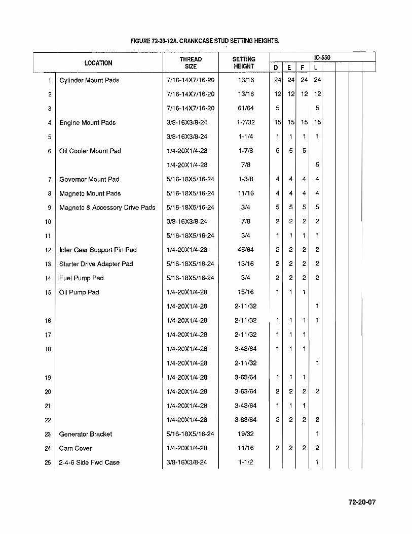
FIGURE 72·20·12A. CRANKCASE STUD SETIING HEIGHTS.
LOCATION THREAD SETIING 10·550
SIZE HEIGHT D E F L
1 Cylinder Mount Pads 7 /16-14X7 /16-20 13/16 24 24 24 24
2 7 /16-14X7 /16-20 13/16 12 12 12 12
3 7 /16-14X7 /16-20 61/64 5 5
4 Engine Mount Pads 3/8-16X3/8-24 1-7/32 15 15 15 15
5 3/8-16X3/8-24 1-1/4 1 1 1 1
6 Oil Cooler Mount Pad 1 /4-20X 1/4-28 1-7/8 5 5 5
1 /4-20X1 /4-28 7/8 5
7 Governor Mount Pad 5/16-18X5/16-24 1-3/8 4 4 4 4
8 Magneto Mount Pads 5/16-18X5/16-24 11/16 4 4 4 4
9 Magneto & Accessory Drive Pads 5/16-18X5/16-24 3/4 5 5 5 5
10 3/8-16X3/8-24 7/8 2 2 2 2
11 5/16-18X5/16-24 3/4 1 1 1 1
12 Idler Gear Support Pin Pad 1 /4-20X1 /4-28 45/64 2 2 2 2
13 Starter Drive Adapter Pad 5/16-18X5/16-24 13/16 2 2 2 2
14 Fuel Pump Pad 5/16-18X5/16-24 3/4 2 2 2 2
15 Oil Pump Pad 1 /4-20X 1/4-28 15/16 1 1 1
1/4-20X1/4-28 2-11/32 1
16 1/4-20X1/4-28 2-11/32 1 1 1 1
17 1/4-20X1/4-28 2-11/32 1 1 1
18 1/4-20X1/4-28 3-43/64 1 1 1
1/4-20X1/4-28 2-11/32 1
19 1/4-20X1/4-28 3-63/64 1 1 1
20 1 /4-20X 1/4-28 3-63/64 2 2 2 2
21 1 /4-20X 1/4-28 3-43/64 1 1 1
22 1 /4-20X 1 /4-28 3-63/64 2 2 2 2
23 Generator Bracket 5/16-18X5/16-24 19/32 1
24 Cam Cover 1/4-20X1/4-28 11/16 2 2 2 2
25 2-4-6 Side Fwd Case 3/8-16X3/8-24 1·1/2 1
72-20-07

FIGURE 72·20·12-C. MISCELLANEOUS STUD SETIING HEIGHTS
THREAD SETIING 10·550 SIZE HEIGHT D E F L
Governor Oil Transfer Collar 1/4-20x1/4-28 15/16 2 2 2 2
Cylinder Exhaust Flange 1/4-20X1/4-28 25/32 4 4 4 4
Oil Pump Housing 1 14-20X1 14-28 21/32 1 1
1/4-20X1/4-28 19/32 1 1
1 14-20X1 14-28 21/32 2 2
1/4-20X1/4-28 19/32 1 1
Oil Filter to Housing Stud 3/4-16X13/16- 9/16 1 1 16
Starter to Starter Adapter 3/8-16X3/8-24 1.00 2 2 2 2
Accessory Drive Adapter 1 14-20X1 14-28 7/8 4 4 4 4
72-20-08

INTENTIONALL Y
LEFT BLANK
72-20-09
72-20-13 HELICAL COIL INSERT INSTALLATION. Helical coil inserts are installed at the factory in four tapped holes of each crankcase bottom flange, in three holes in the left crankcase parting flange, two in the right crankcase parting flange and in four bolt holes at each cylinder head intake port flange. Stainless steel helical coil inserts of special design are installed in all spark plug holes. Any of these inserts may be replaced if damaged. Tools are available through Authorized Distributors of The Heli-Coil Corp., Danbury, Connecticut 60810. The Manufacturer's Bulletin No. 650-R lists both manual and power-driven installing tools, tang break-off tools, special taps and plug gages. A tap drill bulletin is also available from the manufacturer. Helical coil inserts are available in both National Course and National Fine series in lengths equal to 1,1-112 and 2 times nominal diameter and in pipe thread sizes. They are made of either carbon steel, phospher bronze or stainless steel, as specified by part number. They are supplied with or without a notch above the driving tang. The notch is provided to facilitate breaking off the tang in open holes.
Helical coil inserts are coils of wire with a diamond-shaped cross section forming both a male and female thread. The diameter of the insert, when compressed into a special tapped hole at the widest part of the wire (between male and female threads), is equal to the nominal screw size. The special finishing taps, size the casting hole so that the pitch diameter of the female thread of the installed insert conforms to class 3 fit with standard bolt threads or class 4 (tight) fit with standard size studs. The difference in fit is due to a difference in pitch diameters of bolts and studs, so that only one set of helical coil special taps is required for installation of these inserts in both bolt holes and stud holes. Tap drilling depths and tapping depth for helical coil inserts to be installed in blind holes should conform to the recommendations relative to inserts of length equal to 2 times nominal diameter, as tabulated in the manufacturer's Bulletin No. 650-R. Helical coil tap drills and special taps must be run in perpendicular to the machined surface of the casting. Drilling must be done in a drill press after the casting is firmly supported, clamped and alignment checked. The tap will tend to follow the drilled hole. For drilling and tapping aluminum alloy castings, use a lubricant made by mixing one part lard oil with two parts kerosene to prevent overheating of the metal and tearing of the thread.
To remove a damaged helical coil insert, use the proper size of extracting tool for the nominal thread size. Tap it into the insert so that the sharp edges get a good "bite", then turn the tool to the left, and back out the helical coil until it is free. To install a new insert in a properly tapped hole (after blowing out all liquid and chips), slide it over the slotted end of the driving mandrel of the proper size of installing tool and engage the driving tang (bent end) of the helical coil in the mandrel slot; then wind the insert slowly into the tapped hole (See Figure 72-20-13). The outer end of the insert should lie within the first full thread of the hole. Break off the driving tang of a notched helical coil by bending back and forth across the hole with long nose pliers or with a special tang break-off tool.
72-20-14 SPARK PLUG HOLE HELICAL COIL INSERTS. Before attempting to back out a damaged insert, use a sharp pointed tool to pry the teeth at outer end away from the cylinder head metal. Tap a helical coil extracting tool into the insert until it has a good bite (See Figure 72-20-14C). Place a new helical coil in the cut-out side of the installing tool sleeve with its driving tang toward the threaded end. Engage the tang with the slotted end of the driving mandrel and wind the insert into the sleeve so the helical coil can be seen through the slot in the threaded end, and turn the mandrel crank until the insert starts into the cylinder head hole. If the sleeve is not in contact with the head surface, grip sleeve and mandrel and turn until the sleeve touches lightly (See Figure 72-20-14A). Wind the helical coil into the cylinder head until its toothed end lies within the first full thread. The teeth should be in position to enter the depressions made by the original insert. If driven too far, the insert will emerge in the combustion chamber and will have to be wound on through. When the helical coil is in correct position, use longnose pliers to bend the driving tang back and forth across the hole until it breaks off at the notch. Coat a Heli-Coil Corporation No. 520-2 expanding tool threaded end with Alcoa thread lube or a mixture of white lead and oil, and screw it into the new insert until its final thread forces the teeth firmly into the cylinder head metal (See Figure 72-20-14B).
72·20-10

FIGURE 72-20-13 INSTALLING TYPICAL HELICAL INSERT
FIGURE 72-20-14A INSTALLING SPARK PLUG HOLE HELICAL INSERT.
FIGURE 72-20-14B EXPANDING SPARK PLUG HOLE HELICAL INSERT.
FIGURE 72-20-14C REMOVING SPARK PLUG HOLE HELICAL INSERT
A INTERNAL CHAMFER ONl Y (AS RECEIVED) INSTAll AT OUTER END
THESE SURFACES MUST BE SQUARE WITHIN .002 IN. FUll INDICATOR REAOING
SECTION A·A
FIGURE 72-20-17 VALVE ROCKER BUSHING DIMENSIONS.
72-20-11
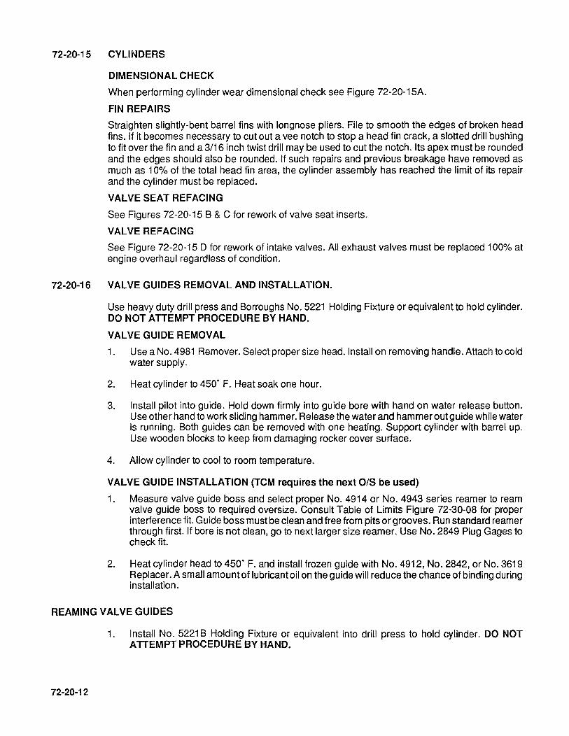
72-20-15 CYLINDERS
DIMENSIONAL CHECK
When performing cylinder wear dimensional check see Figure 72-20-15A.
FIN REPAIRS
Straighten slightly-bent barrel fins with longnose pliers. File to smooth the edges of broken head fins. If it becomes necessary to cut out a vee notch to stop a head fin crack, a slotted drill bushing to fit over the fin and a 3/16 inch twist drill may be used to cut the notch. Its apex must be rounded and the edges should also be rounded. If such repairs and previous breakage have removed as much as 10% of the total head fin area, the cylinder assembly has reached the limit of its repair and the cylinder must be replaced.
VALVE SEAT REFACING
See Figures 72-20-15 B & C for rework of valve seat inserts.
VALVE REFACING
See Figure 72-20-15 0 for rework of intake valves. All exhaust valves must be replaced 100% at engine overhaul regardless of condition.
72-20-16 VALVE GUIDES REMOVAL AND INSTALLATION.
Use heavy duty drill press and Borroughs No. 5221 Holding Fixture or equivalent to hold cylinder. DO NOT ATTEMPT PROCEDURE BY HAND.
VALVE GUIDE REMOVAL
1. Use a No. 4981 Remover. Select proper size head. Install on removing handle. Attach to cold water supply.
2. Heat cylinder to 450' F. Heat soak one hour.
3. Install pilot into guide. Hold down firmly into guide bore with hand on water release button. Use other hand to work sliding hammer. Release the water and hammer out guide while water is running. Both guides can be removed with one heating. Support cylinder with barrel up. Use wooden blocks to keep from damaging rocker cover surface.
4. Allow cylinder to cool to room temperature.
VALVE GUIDE INSTALLATION (TCM requires the next O/S be used)
1. Measure valve guide boss and select proper No. 4914 or No. 4943 series reamer to ream valve guide boss to required oversize. Consult Table of Limits Figure 72-30-08 for proper interference fit. Guide boss must be clean and free from pits or grooves. Run standard reamer through first. If bore is not clean, go to next larger size reamer. Use No. 2849 Plug Gages to check fit.
2. Heat cylinder head to 450' F. and install frozen guide with No. 4912, No. 2842, or No. 3619 Replacer. A small amount of lubricant oil on the guide will reduce the chance of binding during installation.
REAMING VALVE GUIDES
72-20-12
1. Install No. 5221 B Holding Fixture or equivalent into drill press to hold cylinder. DO NOT ATTEMPT PROCEDURE BY HAND.

10.1M3 10939
SIZE
6.605 6.595
STANDARD
.005
.010
.015
........ ---"0" olA.-:"'---eoI
6.650 6.640
TO GAGE LINE
'0' DIAMETER (INCHES)
INTAKE ,
EXHAUST ,
SIZE NEW PARTS SERVICE LIMITS
MINIMUM MAXIMUM MAX
STANDARD 5.251 5.253 5.256
.005 5.256 5.258 5.261
.010 5.261 5.263 5.266
.015 5.266 5.268 5.271
'X' DIAMETER (INCHES) "(" DIAMETER (INCHES)
NEW PARTS SERVICEUMITS SIZE NEW PARTS FOR 'X' DIAMETER MINIMUM MAXIMUM
IS ACTUAl MINIMUM MAXIMUM
5.248 5.250 MEASURED STANDARD 5.245 5.247 "D'DIAMETER PlUS .001 IN.
5.253 5.255 .005 5.250 5.252
5.258 5.260 .010 5.255 5.257
5.263 5.265 .015 5.260 5.262
NOTE: Dimensions shown are finished after honing.
CAUTION: Cylinder assemblies exceeding new parts dimensions shown are acceptable when performing maintenance before engine overhaul. However, piston ring gaps given in the table of limits should be maintained. When engine is being overhauled, all parts must be brought back to new parts limits by rework or replacement. Installed parts should never exceed Service limit. See section 72-3Q..10 New Parts and Service Umits.
FIGURE 72·20-15 A CYLINDER ASSEMBLY DIMENSIONS (INCLINED VALVE).
72-20-13

72·20-14
M------2.50 DIA. Mf\X! ----~ 14-----2.31 DIA. MAX.-----.I
VENTURI INSERT
INTAKE SEAT GRINDING ALL 10-550 ENGINES
PROCEDURE:
I
1. CLEAN UP SEAT WITH 30" STONE. 2. TOP OFF WITH 15" STONE TO ESTABLISH 2.31 MAX SEAT 0.0.
AS REQUIRED.
NOTE: SEAT MUST BE REPLACED IF 2.50 DIA. MAX IS EXCEEDED.
3. UNDERCUT SEAT WITH 45" STONE TO ESTABLISH .07-.12 SEAT WIDTH AS REQUIRED.
FIGURE 72·20·158 INTAKE VALVE SEAT REFACING.
EXHAUST SEAT GRINDING ALL 10-550 ENGINES
PROCEDURE: 1. CLEAN UP SEAT WITH 45" STONE. 2. TOP OFF WITH 15" STONE TO ESTABLISH 1.81 MAX SEAT 0.0.
NOTE: SEAT MUST BE REPLACED IF 2.03 DIA. MAX IS EXCEEDED.
FIGURE 72-20-15C EXHAUST VALVE SEAT REFACING.

INTAKE VALVES
1. Grind valve face to remove any indications of wear.
2. Find new gage diameter on valve face. Gage Dia. = 2.250.
3. Grind stem tip to regain 4.724 to 4.714 distance, stem tip to gage diameter.
4. For approximate amount to be removed from stem tip, measure from position of new gage diameter to valve stem tip. Subtract 4.719 from new length, the remainder will be the amount to be removed from valve stem tip.
5. After grinding, measure overall length of valve if new overall length is less than 4.804 long discard valve and replace with new.
S::'P -~j~----------- l-----------------.j r-
OVERALL LENGTH MUST BE 4.804 OR GREATER
J (
AFTER GRINDING STEM TIP, IF NOT DISCARD VALVE
r-' FACE
1+-----; /1 ___ -_-1I\~,_--_-_-_-+I-r- 2.250 GAGE ~ .-/ _ ~ DIAMETER
~~ ~~ --LrHIS POINT WILL CHANGE AFTER
GRINDING INCREASING DISTANCE FROM STEM TIP TO GAGE DIM. LINE GRIND STEM TIP TO REGAIN DISTANCE OF 4.714 TO 4.724
4.714 FROM STEM TIP 4.724 TO GAGE DIM LINE
NOTE ... Exhaust valves must be replaced 100% at engine overhaul regardless of condition.
FIGURE 72-1S-20D.INTAKE VALVE REFACING
72-20-15

2. Index fixture to proper angle and install cylinder into fixture. Zero in guide with dial indicator.
3. Select proper reamer from Borroughs Tool Catalog. Ream at 400 RPM for high speed steel reamers and 700 RPM for Carbide tip reamers (Do not use carbide tip reamers for hand cutting) use plenty of lubricant.
4. Check finished bore with No. 4933, No. 2848 or No. 3615 plug gages. Refer to Table of Limits Figure 72-30-08 for correct stem hole finished sizes.
NOTE ... See TCM Service Bulletin M85-18 orcurrent revision as applicable for further information.
NOTE ... AII tool numbers are Borroughs PIN's.
72-20-17 VALVE ROCKERS. Worn bushing may be driven out with a suitable drift, and if properly designed, the same tool may be used to drive in new bushings. The rocker must be supported on a ring, which will allow the old bushing to pass through. Press the new bushing in flush with the rocker hub after dipping it in clean lubricating oil. Ream the new bushing to the specified diameter. It is advisable to plug the oil holes with beeswax before reaming. Be sure to remove the wax after reaming. Lightly break the sharp edge at each end. (Refer to Figure 72-20-17).
72-20-18 HYDRAULIC VALVE TAPPETS (See Figure 72-20-18). Stand valve tappet on its flat end. Use a small screwdriver and carefully pry snap ring (1) from body groove, holding down socket (2) with a pushrod until ring has been removed. Invert tappet and catch socket as it drops out. Insert a finger into plunger (3) and withdraw plunger (3), spring (7) and check valve assembly (3, 4, 5, 6). If plunger is stuck in body (8), hold plunger down fully and scrape out carbon deposit. If this obstruction cannot be removed, or if plunger is seized by score marks, the entire assembly must be replaced. Remove spring (7), by turning as if to unwind it while pulling outward. Be careful not to stretch spring out of shape. Remove check ball (4) from plunger by removing retainer (6), lifting spring (5) and ball (4).
NOTE .. .lf at major engine overhaul, hydraulic valve tappets must be replaced 100%.
1. Ring, Retaining 2. Socket, Hydraulic Lifter 3. Plunger 4. Check Ball 5. Ball Check Spring 6. Ball Check Retainer 7. Spring Plunger 8. Body Valve Lifter
FIGURE 72-20-18 HYDRAULIC VALVE TAPPET.
72-20-19 CONNECTING RODS.
72-20-16
CAUTION ... In order to assure good dynamic balance, connecting rod assemblies for new engines are selected in pairs with a maximum weight variation of 112 ounce in opposite bays. This limit cannot be maintained if material is removed from any of the original in a set. Therefore, rods are supplied in matched sets only. Do not remove any material from any rod.
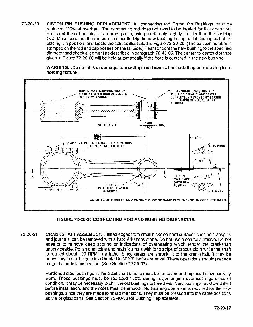
72-20-20 PISTON PIN BUSHING REPLACEMENT. All connecting rod Piston Pin Bushings must be replaced 100% at overhaul. The connecting rod does not need to be heated for this operation. Press out the old bushing in an arbor press, using a drift only slightly smaller than the bushing 0.0. Make sure that the rod bore is smooth. Dip the new bushing in engine lubricating oil before placing it in position, and locate the split as illustrated in Figure 72-20-20. (The position number is stamped on the rod and cap bosses on the far side.) Ream or bore the new bushing to the specified diameter and check alignment as described in paragraph 72-40-05. The center-to-center distance given in Figure 72-20-20 will be held automatically if the bore is centered in the new bushing.
72-20-21
WARNING .•. Do not nick or damage connecting rod I beam when installing or removing from holding fixture .
. 0005 IN. MAX. CONVERGENCE OF THESE AXES PER INCH OF LENGTH (WITH NEW BUSHING)
SECTION A·A
6.627 ~----------6.623--------------~
STAMP eYl. POSITION NUMBER ON NEW RODS (TO BE INSTALL EO ON TOP)
BUSHING 45° (SPLIT TO BE LOCATEO
AS SHOWN)
OIA.
BREAK SHARP EOGES .015/N. X 45°, IF ORIGINAL CHAMFER WAS COMPLETEl Y REMOVEO BY BORING OR REAMING OF REPLACEMENT BUSHING.
:::: :::::
WEIGHTS OF RODS IN ANY ENGINE MUST BE SAME WITHIN % oz. IN OPPOSITE BAYS.
FIGURE 72-20-20 CONNECTING ROD AND BUSHING DIMENSIONS.
CRANKSHAFT ASSEMBLY. Raised edges from small nicks on hard surfaces such as crankpins and journals, can be removed with a hard Arkansas stone. Do not use a coarse abrasive. Do not attempt to remove deep scoring or indications of overheating which render the crankshaft unserviceable. Polish crankpins and main journals with long strips of crocus cloth while the shaft is rotated about 100 RPM in a lathe. Since gears are shrunk fit to the crankshaft, it may be necessary to dip the gear in oil heated to 300°F. before removal. These operations should precede magnetic particle inspection. (See Section 72-30-03).
Hardened steel bushings in the crankshaft blades must be removed and replaced if excessively worn. These bushings must be replaced 100% during major engine overhaul regardless of condition. It may be necessary to chill the old bushings to free them. New bushings must be chilled before installation, and the holes must be smooth. No finishing operation is required for the new bushings, since they are made to final dimensions. They must be pressed into the same positions as the original parts. See Section 72-40-03 for Bushing Replacement.
72-20-17
NOTE ... Crankpins and crankshaft main journals may be reground to the allowable 0.010 inch undersize. Reground crankshafts must be re-nitrided.
CAUTION ... Crankshaft counterweights are matched in pairs with a maximum weight variation of 2 grams, and the complete crankshaft and counterweight assembly is dynamically balanced. As a result, if either counterweight is damaged, it will be necessary to discard both on that cheek and procure a matched pair for replacement.
72-20-22 IDLER GEAR. Excessively worn idler gear bushings are not field replaceable because a special fixture is required to hold the gear during the boring operation, in order to maintain the necessary concentricity of the bushing hole and the gear pitch circle.
72-20-23 MAGNETO AND ACCESSORY DRIVE ADAPTER ASSEMBLY. The magneto and accessory drive adapter bushing must be replaced at major overhaul. Turn down the bushing flange to the body diameter (0.942 inch) and bore out the bushing to a thin shell which can be collapsed. Take care not to cut into the end of the adapter boss or to mark the adapter bore. Press in a new bushing with an arbor press after dipping it in clean engine lubricating oil. The rear pad of the adapter, rather than the studs, must be supported on a parallel block and flat block must be used to exert pressure unless the arbor has a perfect end. Ream or bore the bushing to the specified diameter, then face the flange until it projects forward 1.454-1.458 inch from the adapter parting surface. Chamfer the bore at the flange end 1/16 inch deep on a 45° angle, and slightly break sharp edges at both ends. The bushing hole must be concentric with the adapter pilot shoulder within 0.002 inch and square with the parting surface within 0.002 inch per inch of length. Its flange thrust face must be parallel to the parting surface within 0.002 inch (full indicator reading).
CAUTION ... Before boring a new bushing, plug its oil holes with beeswax to exclude chips from the adapter groove. Be sure to remove the wax completely after the operation.
The old seal may be driven out with a 1/8 inch diameter pin punch inserted through the four oblique oil holes in the bushing boss alternately. If the seal is too tight for that method, drill and tap two opposite machine screw holes in the exposed flange of the seal case to match two screw clearance holes in a pressure plate which can be laid on the adapter studs. Run nuts on two long machine screws; then insert the screws through the pressure plate holes, and screw them into the holes tapped in the seal. To avoid unnecessary stoning of the seal bore, tighten the nuts against the plate to pull the seal squarely from its recess. Smooth any scores in the vacant adapter counterbore. Coat the periphery of a new oil seal with lubricating grease, and press it into the adapter with an arbor press and a flat end block of 1-3/8 inch diameter by 1-1/4 inch length.
72-20-24 TACHOMETER DRIVE HOUSING. Remove the oil seal with a suitable oil seal puller. If the housing counterbore is scored, smooth it with crocus cloth. Spread a film of Grade 50 MHS-27 oil on the perimeter of a new seal. Then press the seal squarely into the housing with its lip pointed outward, facing the oil source.
72-20-25 STARTER DRIVE ADAPTER. The clutch spring sleeve is pre-shrunk and doweled into the housing. If it is necessary to remove the needle bearing in the adapter, a removing driver may be purchased (See Section 1-20-00 Tools).
72-20-18
Check oil feed holes to the starter adapter shaftgear. Hole diameter must be .0918-.0968 to reduce possibility of clogging and causing lubrication loss to starter adapter clutch spring. The oil feed hole comes off the rear cam bearing of the 1-3-5 crankcase half and intersects a short hole in the center of the needle bearing counterbore. Hole can be enlarged to diameter shown above after removal of the starter adapter.
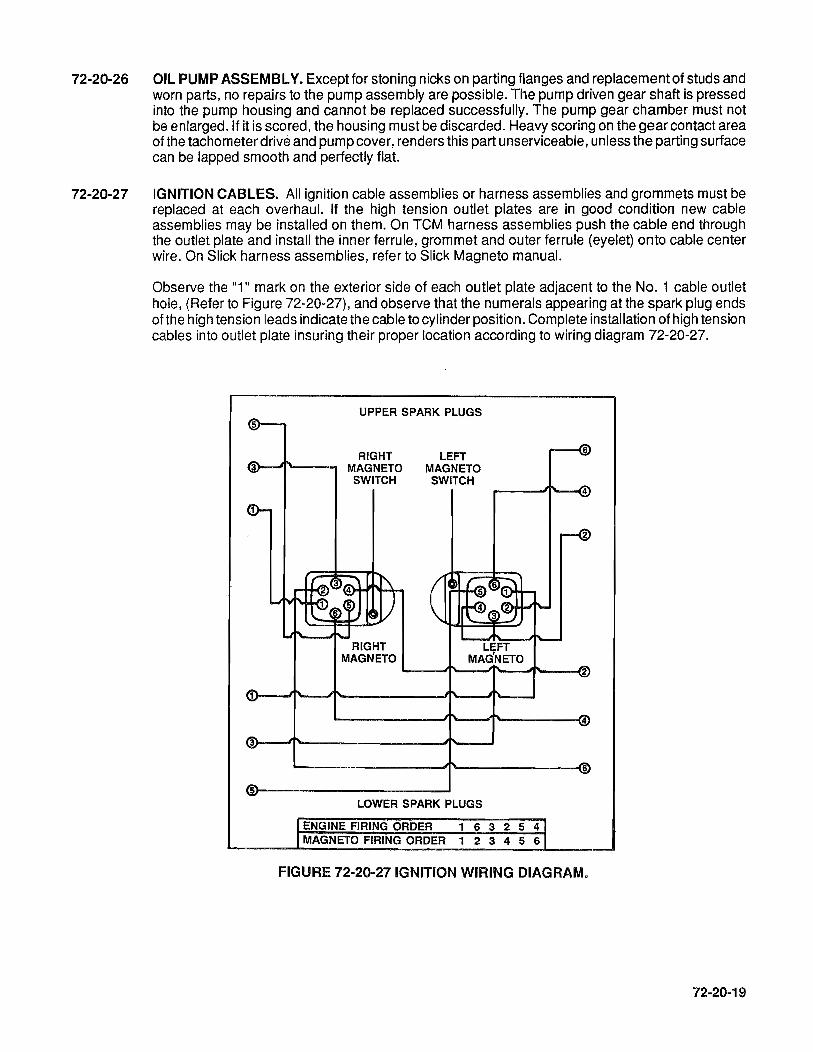
72-20-26 OIL PUMP ASSEMBLY. Except for stoning nicks on parting flanges and replacement of studs and worn parts, no repairs to the pump assembly are possible. The pump driven gear shaft is pressed into the pump housing and cannot be replaced successfully. The pump gear chamber must not be enlarged. If it is scored, the housing must be discarded. Heavy scoring on the gear contact area of the tachometer drive and pump cover, renders this part unserviceable, unless the parting surface can be lapped smooth and perfectly flat.
72-20-27 IGNITION CABLES. All ignition cable assemblies or harness assemblies and grommets must be replaced at each overhaul. If the high tension outlet plates are in good condition new cable assemblies may be installed on them. On TCM harness assemblies push the cable end through the outlet plate and install the inner ferrule, grommet and outer ferrule (eyelet) onto cable center wire. On Slick harness assemblies, refer to Slick Magneto manual.
Observe the "1" mark on the exterior side of each outlet plate adjacent to the No.1 cable outlet hole, (Refer to Figure 72-20-27), and observe that the numerals appearing at the spark plug ends ofthe high tension leads indicate the cable to cylinder position. Complete installation of high tension cables into outlet plate insuring their proper location according to wiring diagram 72-20-27.
UPPER SPARK PLUGS
RIGHT MAGNETO SWITCH
RIGHT MAGNETO
LEFT MAGNETO SWITCH
LEFT MAG'NETO
4
2
~----------~1'--~'"--------~4
3r-~T---------------~~~
5~------------------~ LOWER SPARK PLUGS
ENGINE FIRING ORDER 1 6 3 2 5 4 MAGNETO FIRING ORDER 1 2 3 4 5 6
6
FIGURE 72·20-27 IGNITION WIRING DIAGRAM.
72-20-19

72-20-20
INTENTIONALL Y
LEFT BLANK
72-30-00 72-30-01
72-30-02
72-30-03
72-30-04
72-30-05
72-30-06
72-30-07
72-30-08
72-30-09
72-30-10
72-30-11
72-30-12
72-30-13
72-30-14
72-30-15
SECTION 72~30 INSPECTION
INSPECTION General
Visual Inspection
Magnetic Particle Inspection
Ultrasonic Inspection
Flourescent Penetrant Inspection
Dimensional Inspection
Dimensional Limits
Table of Limits
Original Dimension
New Parts and Service Limits
Critical New Parts Dimensions
Protective Coating
Application of Alodine
Repair of "Alodized" Surfaces
Enamel Coatings
72-30-01

72·30-02
INTENTIONALL Y
LEFT
BLANK

72-30-00 INSPECTION
72-30-01 GENERAL
The following definitions apply to terms used to describe kinds of damage for which parts should be inspected.
ABRASION: Scratching of a surface, either by motion while in contact with another part, by mechanical cleaning, or resurfacing with abrasive cloth or lapping compound.
BURNING: As applied to valve heads, this term indicates roughening or erosion due to high temperature gases escaping past valve faces. In other instances, it indicates drawing of the temper of steel parts to a soft (blue) condition as a result of overheating, in absence of lubrication on moving surfaces such as gear teeth, subject to high loading.
BURR: A sharp projection of metal from an edge, usually the result of drilling, boring, countersinking, etc., but may also be caused by excessive wear of one or both surfaces adjacent to the burred edge.
CORROSION: Deterioration of a surface, usually caused by oxidation of metal.
ELONGATION: Stretching or increase in length.
FRETTING: Scuffing or deterioration of a metal surface caused by vibration or chattering against another part. A fretted steel surface may appear dull, scuffed, or corroded, depending on length of time subjected to the action.
GALLING: Excessive friction between two metals resulting in particles of the softer metal being torn away and "welded" to the harder metal.
INDENTATION: Dents or depressions in a surface caused by severe blows.
OXIDATIONS: Chemical combining of a metal with atmospheric oxygen. Aluminum oxide forms a tough, hard film and protects the surface from further decomposition; however, iron oxides do not form a continuous cover or protect underlying metal. Oxidation of steel parts is progressive and destructive.
PITTING (OR SPALLlNG): Small, deep cavities with sharp edges. May be caused in hardened steel surfaces by high impacts or in any smooth steel part by oxidation.
RUNOUT: Eccentricity or wobble of a rotating part. Eccentricity of two bored holes or two shaft diameters. A hole or bushing out of square with a flat surface. Usually measured with a dial indicator, and limits stated indicate full deflection of indicator needle in one revolution of part or indicator support.
SCORING: Deep grooves in a surface caused by abrasion, when fine, hard particles are forced between moving surfaces, as in a bearing and journal, or by galling when a moving part is not supplied with lubricant.
72·30-03

PROTECTION FROM CORROSION: Coat all steel parts with corrosion preventive oil. At inspection, parts are wiped free of oil, to provide easy handling and true dimensional reading. Immediately after inspection, parts must be cleaned to eliminate fingerprints and contaminates, completely recoated with corrosion preventive oil and packaged properly to prevent damage.
72-30-02 VISUAL INSPECTION. Parts without critical dimensions, small parts, running parts, and others of major importance, must be inspected visually with at least a 1 OX magnifying glass under good light for surface damage such as nicks, dents, deep scratches, visible cracks, distortion, burned areas, pitting, pick-up of foreign metal, and removal of enamel coating. Visual inspection should also determine the need for further cleaning of obscure areas. Inspect all studs for possible bending, looseness or partial removal. Inspect all threaded parts for nicks and other damage to the screw threads. After visual inspection, the engine parts should be in three groups: apparently serviceable parts, repairable parts and parts to be discarded.
72-30-03 MAGNETIC PARTICLE INSPECTION. Inspection by the Magneflux method must be conducted on all ferrous parts listed in Section 72-30-03, and in accordance with the methods and data in the table before dimensional inspection. The Magnaglow method is recommended whenever the necessary equipment is available. This method employs magnetic particles coated with a flourescent organic material which may be illuminated with a "black light", as in the Zyglo process, to amplify an indication of weakness. If a crankshaft is doubtful after a circular magnetization and inspection, demagnetize and remagnetize it longitudinally for further inspection.
72-30-04
NOTE ... Before magnetic particle inspection, piston pins and valve rocker shafts must be pOlished with crocus cloth.
CAUTlON ... Before magnetic particle inpection of any part, plug small holes leading to obscure cavities with tight-fitting wood plugs or with a hard grease which is soluble in lubricating oil to prevent particles from lodging in places where they would be difficult to remove, and in places that are not subject to visual inspection. After magnetic particle inspection, remove all such plugs and clean the part thoroughly in solvent, and dry with compressed air. Check for complete demagnetization.

Part
Crankshaft
Connecting Rod
Camshaft
Piston Pin
Rocker Arms
Gears to 6 Inch Diameter
Gears over 6 Inch Diameter
Shafts
Thru Bolts Rod Bolts
Cylinder Barrels
NOTE:(*)
72-30-03 MAGNETIC PARTICLE INSPECTION
FLOURESCENT METHOD PREFERRED, WET CONTINUOUS PROCEDURE REQUIRED
*Method of AC or DC Critical Areas Magnetization Amperes
Circular and Journals, fillets, oil
Longitudinal 2000 holes, thrust flanges, prop flange.
Circular and 1500 All areas. Longitudinal
Circular and 1500 Lobes, Journals
Longitudinal drilled hole edges.
Circular and 1000 Shear planes, ends,
Longitudinal center.
On Conductor Bar 1000 Pad, socket under and single. Between Heads 800 side arms and boss.
Circular or on 1000 to 1500
Teeth, Splines, Center Conductor Keyways.
Shaft Circular Teeth Between 1000 to 1500 Teeth, Splines Heat Two Times 90°
Circular and 1000 to 1500 Splines, Keyways, Longitudinal Change of Section
Circular and 500 Threads Under Head. Longitudinal
Circular and 1500 All areas. Lo ngitud inal
Possible Defects
Fatigue cracks, heat cracks, flange cracks, from prop strike.
Fatigue cracks.
Heat cracks. Fatigue cracks
Fatigue cracks.
Fatigue cracks.
Fatigue cracks.
Fatigue cracks,
Fatigue cracks, Heat Cracks.
Fatigue cracks.
Fatigue cracks. Heat cracks.
LONGITUDINAL MAGNETISM: Current applied to solenoid coil surrounding the work.
CIRCULAR MAGNETISM: Current passed through work or through non-magnetic conductor bar inserted through work.
72-30-05
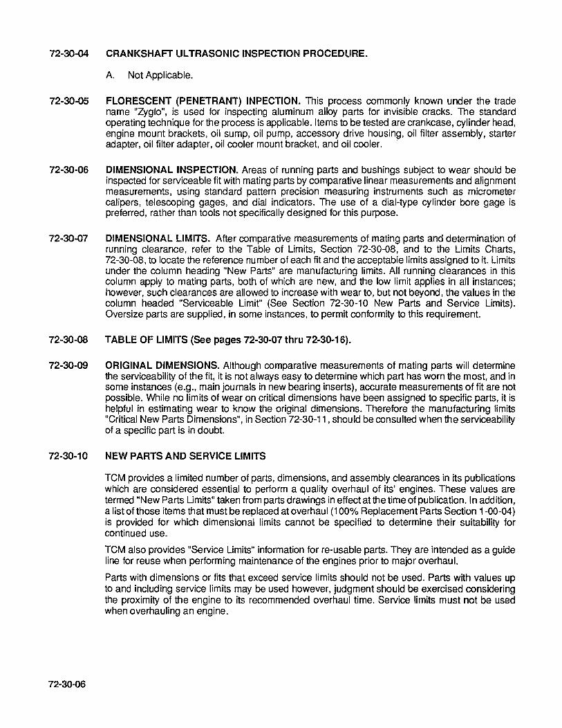
72-30-04 CRANKSHAFT ULTRASONIC INSPECTION PROCEDURE.
A. Not Applicable.
72-30-05 FLORESCENT (PENETRANT) INPECTION. This process commonly known under the trade name "Zyglo", is used for inspecting aluminum alloy parts for invisible cracks. The standard operating technique for the process is applicable. Items to be tested are crankcase, cylinder head, engine mount brackets, oil sump, oil pump, accessory drive housing, oil filter assembly, starter adapter, oil filter adapter, oil cooler mount bracket, and oil cooler. .
72-30-06 DIMENSIONAL INSPECTION. Areas of running parts and bushings subject to wear should be inspected for serviceable fit with mating parts by comparative linear measurements and alignment measurements, using standard pattern precision measuring instruments such as micrometer calipers, telescoping gages, and dial indicators. The use of a dial-type cylinder bore gage is preferred, rather than tools not specifically designed for this purpose.
72-30-07 DIMENSIONAL LIMITS. After comparative measurements of mating parts and determination of running clearance, refer to the Table of Limits, Section 72-30-08, and to the Limits Charts, 72-30-08, to locate the reference number of each fit and the acceptable limits assigned to it. Limits under the column heading "New Parts" are manufacturing limits. All running clearances in this column apply to mating parts, both of which are new, and the low limit applies in all instances; however, such clearances are allowed to increase with wear to, but not beyond, the values in the column headed "Serviceable Limit" (See Section 72-30-10 New Parts and Service Limits). Oversize parts are supplied, in some instances, to permit conformity to this requirement.
72-30-08 TABLE OF LIMITS (See pages 72-30-07 thru 72-30-16).
72-30-09 ORIGINAL DIMENSIONS. Although comparative measurements of mating parts will determine the serviceability of the fit, it is not always easy to determine which part has worn the most, and in some instances (e.g., main journals in new bearing inserts), accurate measurements of fit are not possible. While no limits of wear on critical dimensions have been assigned to specific parts, it is helpful in estimating wear to know the original dimensions. Therefore the manufacturing limits "Critical New Parts Dimensions", in Section 72-30-11, should be consulted when the serviceability of a specific part is in doubt.
72-30-10 NEW PARTS AND SERVICE LIMITS
72-30-06
TCM provides a limited number of parts, dimensions, and assembly clearances in its publications which are considered essential to perform a quality overhaul of its' engines. These values are termed "New Parts Limits" taken from parts drawings in effect at the time of publication. In addition, a list of those items that must be replaced at overhaul (100% Replacement Parts Section 1-00-04) is provided for which dimensional limits cannot be specified to determine their suitability for continued use.
TCM also provides "Service Limits" information for re-usable parts. They are intended as a guide line for reuse when performing maintenance of the engines prior to major overhaul.
Parts with dimensions or fits that exceed service limits should not be used. Parts with values up to and including service limits may be used however, judgment should be exercised considering the proximity of the engine to its recommended overhaul time. Service limits must not be used when overhauling an engine.
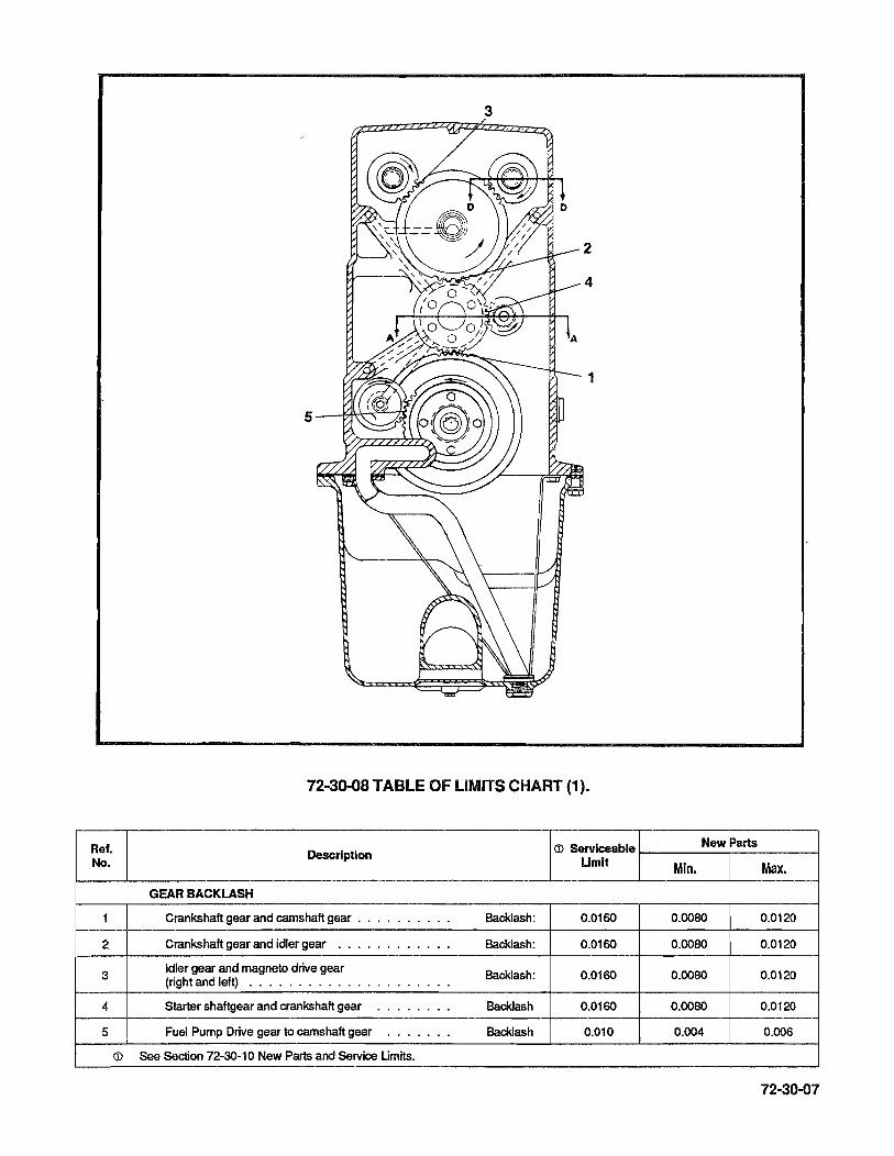
3
1
72-3Q..08 TABLE OF LIMITS CHART (1).
Ref. eD Serviceable New Parts
No. Description
Urnlt Min. Max.
GEAR BACKLASH
1 Crankshaft gear and camshaft gear . . . . ............ Backlash: 0.0160 0.0080 0.0120
2 Crankshaft gear and idler gear ........................ Backlash: 0.0160 0.0080 0.Q120
3 Idler gear and magneto drive gear Backlash: 0.0160 0.0080 0.0120 (right and left) ..........................................
4 Starter shaftgear and crankshaft gear ............... Backlash 0.0160 0.0080 0.Q12O
5 Fuel Pump Drive gear to camshaft gear e ............ Backlash 0.010 0.004 0.006
eD See Section 72-30-10 New Parts and Service Urnits.
72-30-07

Ref, No,
1
2
3
4
4
5
6
7
S
9
10
11
12
13
14
15
16
17
18
19
20
21
22
23
24
25
26
27
72-30"()S
FIGURE 72-30-08 TABLE OF LIMITS
CHART (2)
Description
CYUNDER AND HEAD ASSEMBLY
Cylinder bore (lower 4.25" of barrel) .. · .. · .... Diamelar:
Cylinder bore choke (at 5.75" & 6.50" from open end of Diameter: barrel) ................ · .......
Cylinder bore out-of-round ........ · .... · ..
Cylinder bore (POlO). Allowable ................... · . eNersize:
Cylinder bore (P015). Allowable . . . . . . . . . . . · . · ..... · . eNersize:
Cylinder bore surface roughness (Nitrided Barrels) Cross Hatch · ....... . . . . . . · .... · .. Angle Microfinish (measured in direction of piston travel) · . RMS:
Cylinder barrel in crankcase ...... · ...... Diameter:
Intake valve seat insert in cylinder head. · ....... Diamelar:
Intake valve guide in cylinder head · . · .... · . Diamelar:
Exhaust valve guide in cylinder head · .. · ... Diameter:
Exhaust valve seat insert in cylinder head ..... · .. Diamelar:
Intake valve seat. . . . . . . . . . . . · .. · . · . Width:
Exhaust valve seat ........... · ... · . · . Width:
Exhaust valve seat-ta-valve guide axis · ..... · .. Angle:
Intake valve seat-to-valve guide axis . . · .... · . Angle:
ROCKER ARMS AND SHAFTS
Rocker shaft in cylinder head bosses .......... Diame1er:
Rocker shaft in rocker arm bearing · ....... · .. Diameter:
Rocker ann Bushing (Inside) Finish ... · .. · ...... BoreDiamelar:
Rocker arm · ............... · .. · ... Side Clearance:
Rocker ann to rotoooil ............... · .. Clearance:
Rocker ann grind ..... . . . . " . · .... · . Width:
Intake valve in gUide ........... · ....... Diamelar:
Exhaust valve in guide (nitralloy) . . . · .... · .. Diame1er:
Intake valve face (to stam axis) .... · ....... Angle:
Exhaust valve face (to slam axis) ......... · .. Angle:
Intake valve · ............. · ...... Length:
Exhaust valve .............. · .... · .. Length:
Intake and exhaust valve seat-ta-slam (full indicator reading) ...................... · .. Runout:
Valve Rocker toe to Valve Stam (Dry lif1er) ....... PISTONS, RINGS AND PINS
Piston (bottom of skirt) in cyHnder . . . . . . . . . . . • Diame1er:
CD Servlceabl New Parts
Umlt Min, Max,
SEE FIGURE 72-2O-15A
SEE FIGURE 72-2O-15A
0.0020 0.0000 0.0010
SEE FIGURE 72-2O-15A
SEE FIGURE 72-2O-15A
- 22'-32' -15 25
- 0.0040L O.OlooL
- 0.0090T 0.012OT
- 0.0010T O.OO25T
- 0.0015T O.OO30T
- 0.0070T O.Ol00T
SEE FIGURE 72-2O-15B
SEE FIGURE 72-2O-15C
- 45'00' -- 59'45' 60'15'
- O.OOO7L 0.0027L
- 0.0017L O.OO32L
- 0.7505 0.7515
0.0350L 0.0020l 0.015L
- 0.020 -- - 0.34
O.oo50l 0.0010L 0.OO42L
0.ooS7L 0.0035l 0.OO62L
- 59'45' 60'15
- 45'00' 45'30'
SEE FIGURE 72-20-15 D
REPLACE 100%
0.0040 0.0000 0.0015
- 0.0600 0.2000
O.014L O.ooSl O.011L

Ref. No.
28
29
30
31
32
33
34
35
36
37
38
39
40
41
42
43
44
45
46
47
48
FIGURE 72·30-08 TABLE OF LIMITS CHART (2) (cent'd)
Description
Top piston ring in groove · .. · .. · . Side Clearance:
Second piston ring in groove · . · . · . Side Clearance:
Third piston ring in groove . . · . · . · . Side Clearance:
Fourth piston ring in groove · .. · . Side Clearance:
Top ring gap at 6.44 from open end of barrel Gap:
Second ring gap at 6.44 from open end of barrel · . Gap:
Third ring gap at 6.44 max from open end of barrel . Gap:
Fourth ring gap at 1.00 max from open end of barrel Gap:
Piston pin in piston (standard or O.OOS" oversize) Diameter:
Piston pin ......... · .. · . · . . .. Diameter:
Piston pin (0.005" oversize) · . Diameter:
Piston pin in cylinder. . . . . . · . End Clearance:
Piston pin in connecting rod bushing Diameter:
Bushing in connecting rod . · .. Diameter:
Bolt in connecting rod . . . · .. Diameter:
Connecting rod bearing on crankpin . Diameter:
Connecting rod on crankpin · .... End Clearance:
Connecting bearing and bushing twist or convergence per inch of length ............ · .......
CRANKCASE AND ATTACHED PARTS
Hydraulic Tappet in crankcase ..... · ....... Diameter:
SPRING TEST DATA
Inner Valve spring (631521) compressed to 1.230 inch Load:
length · ......................... Inner valve spring (631S21) compressed to 1.746 inch
Load: length · ......................... Outer valve spring (637837) compressed to 1.275 inch
Load: length · ......................... Outer valve spring (637837) compressed to 1.791 inch
Load: length · .................... . . Installed outer valve spring · ......... . . . . . Height:
eD See Section 72-30-10 New Parts and Service Limits.
NOTE ... After dimensions, L = Loose, T = Tight
eD Serviceabl New Parts
Umlt Min. Max.
0.0060L 0.001SL 0.0040L
0.0060L 0.001SL 0.0040L
0.0075L 0.003SL 0.0055L
0.01OOL 0.0060L 0.0080L
- .010 .030
- .010 .030
- .010 .030
- .010 .030
- 0.0001L 0.0013L
- 1.1243 1.1245
- 1.1293 1.1295
0.090L 0.0310L 0.0480L
0.0040L 0.0022L 0.0026L
- 0.002ST 0.0050T
- 0.0000 0.0018L
0.0060L 0.0009L 0.0034L
0.0160 0.0060 0.0110
0.0010 0.0000 0.0005
0.003SL 0.0010L 0.0025L
82 Lbs. 87Lbs. 97 Lbs.
29 Lbs. 32 Lbs. 38 Lbs.
118 Lbs. 126 Lbs. 140 Lbs.
46 Lbs. 49 Lbs. 55 Lbs.
- - 1.791
72-30-09
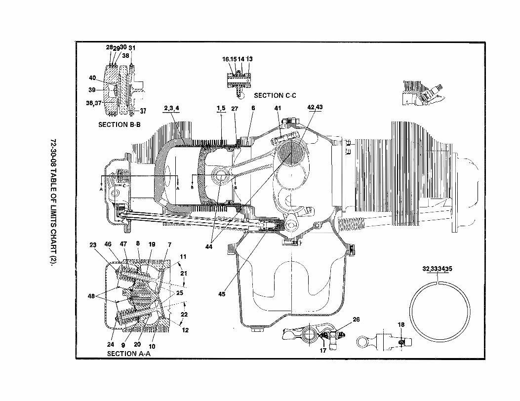
;j • w o • ..... o
oo-J N W g co
~ III rm o ." r-!: ~ o
40
SECTION B-B
~ :xl 23 46 47 8 19 ~ -I\) -.
24 9 20 10 SECTION A-A
16,1514'13
, SECTION C-C
1.5 27
32.33[34,35
45
26 18
~

INTENTIONALL Y
LEFT
BLANK
72·30·11
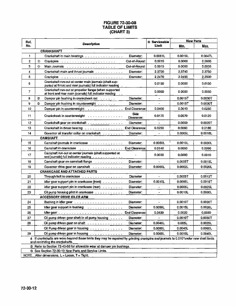
Ref. No.
1
2
3
4
S
6
7
8
9
10
11
12
13
14
lS
16
17
18
19
20
21
22
23
24
2S
26
27
28
29
CD
CD
(2)
(2)
FIGURE 72-30-08 TABLE OF LIMITS
(CHART 3)
Description
CRANKSHAFT
Crankshaft in main bearings ......... . . . . . . Diameter:
Crankpins ..................... Out-of-Round:
Main Joumals ................... Out-of-Round:
Crankshaft main and thrust journals . . . . . . . . . . . Diameter:
Crankpins ........................ Diameter:
Crankshaft run-out at center main journals (shaft sup-ported at thrust and rear journals) full indicator reading . Crankshaft run-out at propeller flange (when supported at front and rear main journals) full indicator reading ..
Damper pin bushing in crankcheek ext ...... Diameter:
Damper pin bushing in counterweight ....... Diameter:
Damper pin in counterweight ............... End Clearance
Crankcheek in counterweight Side · ............. Clearance:
Crankshaft gear on crankshaft . . . . . . . . . . . . . . Diameter:
Crankshaft in thrust bearing ............... End Clearance
Governor oil transfer collar on crankshaft · ....... Diameter: CAMSHAFT
Camshaft joumals in crankcase ............. Diameter:
Camshaft in crankcase ................. End Clearance Camshaft run-out at center journals (shaft supported at end journals) full indicator reading ............ -Camshaft gear on camshaft flange ........... Diameter:
Governor drive gear on camshaft ............ Diameter: CRANKCASE AND ATTACHED PARTS
Through bolt in crankcase ................ Diameter
Idler gear support pin in crankcase (front) · ....... Diameter:
Idler gear support pin in crankcase (rear) · ....... Diameter:
Oil pump housing pilot in crankcase . . . . . . . . . . . Diameter: ACCESSORY DRIVE IDLER ARM
Bushing in idler gear . . . . . . . . . . . . . . . . . . . Diameter:
Idler gear support in bushing · ............. Diameter:
Idler gear ......................... End Clearance
Oil pump driven gear shaft in oil pump housing ..... Diameter:
Oil pump driven gear on shaft · ....... . . . . . . Diameter:
Oil Pump driven gear in housing . . . . . . . . . . . . . Diameter:
Oil pump driven gear in housing ............. Diameter:
(3) Serviceable New Parts Umlt Min. Max.
0.0061L 0.0018L 0.0047L
O.oolS 0.0000 O.ooOS
O.oolS 0.0000 O.OOOS
2.3720 2,3740 2.37SO
2.2470 2.2490 2.2SOO
O.OlSO 0.0000 O.OlSO
O.OOSO 0.0000 O.OOSO
- O.oolST 0.003OT
- O.oolST 0.003OT
0.0400 0.0010 0.02SO
0.0170 0.0070 0.0120
- 0.0000 0.002OT
0.02SO 0.0080 0.0180
- O.ooOSL 0.0018L
O.ooSOL 0.0010L 0.003OL
0.0140 O.OOSO 0.0090
0.0030 0.0000 0.0010
- O.ooOST O.oolSL
O.oo60L 0.0002L 0.002OL
- O.ooOST 0.0013T
0.0010L O.ooOSL 0.001ST
- O.ooOSL 0.002SL
- 0.0010L 0.003OL
- 0.0010T 0.003OT
O.ooSOL O.oolSL O.oo35L
0.0430 0.0020 0.0330
- 0.0010T 0.003OT
0.004OL O.ooSL 0.002SL
O.oo80L 0.OO4OL O.oo60L
O.oo60L O.oolSL 0.004OL Ii If crankshafts are worn beyond these limits they may be repaired by grinding crankpins and journals to 0.01 O·under new shaft limits and renitriding the crankshafts. <2l Refer to Section 72-40-03 for allowable wear at damper pin bushings. (3) See Section 72-30-10 New Parts and Service Umits.
NOTE ... After dimensions, L = Loose, T = Tight.
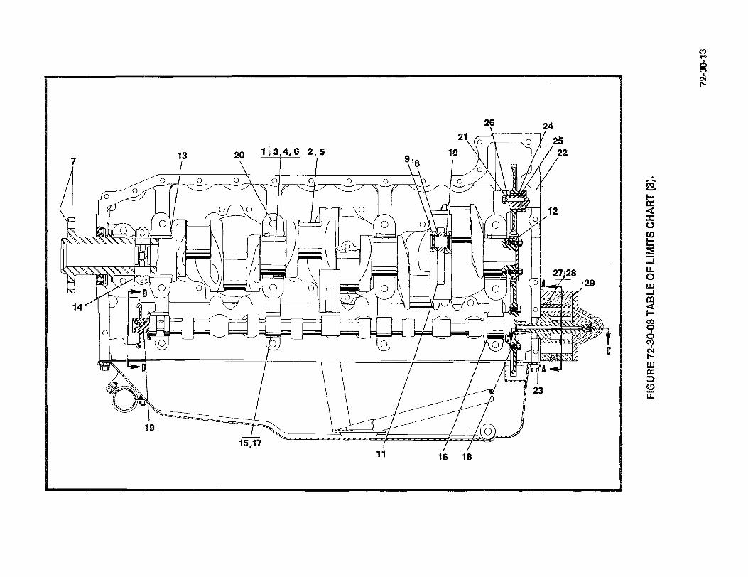
26
7 1 ;314,'6 2,5
o o o
o
11 16 18
. -M -li: « :t: o (J)
t:: :l: ::i u. o W ....I r:c ~ co q o c;t)
~ w a: ::) (!)
u:::
M ,.. ~
I
N t--

FIGURE 72-30-08 TABLE OF LIMITS
(CHART 4)
Ref. No. Description
CRANKCASE AND ATTACHED PARTS
1 Governor drive shaft in crankcase ... · ..... · .. Diameter:
OIL PRESSURE RELIEF VALVE ASSEMBLY 2 Oil pressure relief valve adjusting screw in plunger · .. Diameter:
OIL PRESSURE PUMP ASSEMBLY
3 Oil pump driver gear in pump housing ... Diameter
4 Oil pump driver gear shaft in pump housing Diameter:
5 Oil pump driven gear in pump housing · . End Clearance
6 Oil pump driver gear in pump housing ... End Clearance
7 Oil pump driver gear shaft in cover oil pump Diameter:
8 Oil pump driver gear shaft in tachometer drive bevel gear Diameter:
TACHOMETER DRIVE ASSEMBLY
9 Tachometer drive shaft in oil pump cover Diameter:
10 Oil seal in tachometer drive housing ... Diameter:
GEAR BACKLASH
11 Oil pump driver and driven gears ......... Backlash:
12 Tachometer drive gear and tachometer driven gear. Backlash
13 Governor drive gear and governor driven gear ... Backlash:
SPRING TEST DATA
14 ® Oil temperature control valve 0.090 inches minimum
Temperature: travel at ...................... . .
® Oil temperature control valve must close between Oil Tempera-
ture: @ Oil temperature control valve 0.16 inches minimum
Temperature travel at ...................... · .. @ Oil temperature control valve must close between Oil Tempera-
ture
15 Relief valve spring (634150) compressed to 1.25 inch
Load: length ........................ 16
Oil filter by-pass valve spring (631478) in pump com-load:
pressed to 1.09 inch length . . . . . . · ...... ... G) See Section 72-30-10 New Parts Service Limits.
® 10-550 D, E & F. @ 10-550 L. NOTE ... After dimensions, l = Loose, T = Tight
72-30-14
G) Serviceable New Parts Limit Min. Max.
0.0050l 0.0014l O.OO34L
- 0.010 0.025
- 0.0015L 0.0040L
0.0045l 0.0015L 0.0030
0.0050 0.0005 0.0030
0.0050 0.0005 0.0030
0.0045l 0.0015l 0.0030l
0.0040l 0.0005l 0.0025L
0.0045l 0.0015l 0.0030l
- 0.0010T 0.0070T
0.016 0.009 0.013
0.0120 0.0040 0.0080
0.0090 0.0020 0.0060
- 120' 170'
- 168' 172'
- 135' 173'
- 171' 175'
30 Lbs. 32 Lbs. 37 Lbs.
5.0 Lbs. 5.6 lbs. -

3 11 2
15
SECTION B - B
SECTION A-A
4
5,6
10-55Q-O,F&L 10-550-E
9
10 7
12 8
10
SeCTION C-C SeCTION C-C
13 14
-<, "
SECTION 0-0
FIGURE 72·30-08 TABLE OF LIMITS CHART (4).
72-30-15

Ref. No.
1
2
3
4
5
6
7
8
9
10
11
12
13
14
15
16
17
18
19
20
21
22
23 CD
24
25
26
27
28
29
30
31
32
33
FIGURE 72-30-08 TABLE OF LIMITS
(CHART 5)
Description
Magneto and accessory drive adapter pilot in crankcase Diameter:
Starter shaftgear needle bearing hole crankcase ... Diameter: LEFT AND RIGHT MAGNETO AND ACCESSORY
Bushing in magneto and accessory drive adapter. ... Diameter:
Magneto and accessory drive gear in adapter bushing Diameter:
Oil seal in adapter . . . . . . . . . . . . . . . · . Diameter:
Sleeve in magneto and accessory drive gear . . . . . . Diameter:
Magneto and accessory drive gear ........... End Clearance
Magneto coupling retainer on magneto and accessory Diameter: drive gear sleeve ....................
Magneto coupling retainer in magneto drive gear slot. Side Clearance:
Magneto coupling rubber bushings on magneto drive Side lugs ................ · .. . . · . · . Clearance:
Magneto pilot in crankcase · .............. Diameter: STARTER DRIVE
Starter shaftgear in bearing · ...... · . · . Diameter:
Starter shaftgear front (bearing) journal . · . Diameter:
Starter shaftgear in clutch drum bearing . · . Diameter:
Starter clutch drum on starter shaftgear . · . · . Diameter:
Clutch spring sleeve in starter adapter · . · . Diameter:
Starter shaftgear in ball bearing . . · . · . Diameter:
Starter shaftgear in oil seal sleeve . · . · . · . Diameter:
Bearing in starter adapter cover . . · . · . · . Diameter:
Oil seal in starter adapter cover . . · . · . · . Diameter:
Starter adapter cover pilot in starter adapter · . · . Diameter:
Worm wheel gear ................ · . End Clearance
Clutch spring on starter shaftgear (over knurl) .. · . Diameter:
Clutch spring in clutch spring sleeve. . . . . . . Diameter:
From center line of worm gearshaft to starter adapter thrust pads . . . . . . . . . . . . . . · . · .. · . Needle bearing hole starter adapter . · ....... Diameter:
Ball Bearing in starter adapter . . . ... . . · . Diameter:
Worm gearshaft in needle bearing . · . · . Diameter:
Worm gearshaft in ball bearing .. · . · . Diameter:
Starter worm gear on shaft · ... · .. Diameter:
Starter spring on worm drive shaft. · . · .. Diameter:
Starter pilot to starter drive adapter · . · . · .. · .. Diameter:
Starter drive tongue to worm shaft drive slot Side · ..... Clearance:
Starter worm wheel gear and worm gear · . · ..... Backlash:
Governor drive gear and governor driven gear · .... Backlash:
CD When sandblasted finish diameter is worn to RMS, replace sleeve. ~ See Section 72-30-10 New Parts and Service Umits.
NOTE ... After dimensions, L = Loose, T = Tight
72-30-16
~ Serviceable New Parts Limit Min. Max.
- 0.0000 0.0030l
- 0.9995 1.0005
- 0.0010T 0.0040T
.00050l 0.0015l 0.0035l
- 0.0010T 0.0070T
- 0.0010T 0.0040T
- 0.0110l O.O77l
0.0550l 0.0250l 0.0400l
0.0400l 0.0020T 0.280l
- 0.0100l 0.0520T
- 0.0010l 0.0050l
0.0031l 0.0005l 0.0015l
0.7480 0.7495 0.7500
- 0.0005l 0.0020l
0.0055l 0.0020l 0.0040l
- 0.0030T 0.0050T
- O.OOOll 0.0005T
- 0.0000 0.0015l
- O.OOOlT 0.0010l
- 0.0017T 0.0063T
- 0.OO10l 0.0030l
0.0800 0.0380 0.0720
0.0130l 0.0060l 0.0090l
0.0270T 0.0310T 0.0380T
0.2520 0.2460 0.2480
- 0.7482 0.7495
- o.ooon 0.0010l
0.5600 0.5615 0.5625
- o.ooon 0.0007l
0.0040l 0.0005l 0.0025l
- 0.0050l 0.0250l
- 0.0010l 0.0065l
0.0300l 0.0100l 0.0210l
0.0200 0.0090 0.0130
0.009 0.002 0.006

23 15 22 14
12 13 11
9 6 8 7 4 1 3
5
SECTION 0-0 29 30 26 31
32
SECTION E-E
SECTION 8- 8
FIGURE 72-30-08 TABLE OF LIMITS CHART (5).
72-30-17

72-30-11 CRITICAL NEW PART DIMENSIONS
PART NAME FEATURE NEW DIMENSION
(INCHES)
Rocker Shaft Boss Bore 0.7495 - 0.7510 Cylinder Head Intake Valve Guide Bore (Installed) 0.4350 - 0.4377
Exhaust Valve Guide Bore (Installed) 0.4375 - 0.4395
Valve Rocker Shaft Outside Diameter 0.7483 - 0.7488
Valve Rocker Bushings Inside Diameter 0.7505 - 0.7515
Intake Valve Stem Diameter 0.4335 - 0.4340
Exhaust Valve Stem Diameter 0.4333 - 0.4340
<D Diameter at Top 5.2090 - 5.2130 <D Diameter Below 1 st Groove 5.2150 - 5.2190
Piston (Standard) <D Diameter at Bottom 5.2420 - 5.2430 Pin Bore Diameter 1 .1246 - 1 .1250 Third Ring Groove Width 0.1910 - 0.1920 Fourth Ring Groove Width 0.1000 - 0.1010
Piston Pin Assembly Length (Including Plugs) 5.2050 - 5.2200
Connecting Rod Bushing Bore Diameter 1.1267 - 1 .1269 Bushing Center-to-Crankpin Center 6.6230 - 6.6270
Crankshaft Assembly Damper Pin Bushing I.D. (16) 0.6240 - 0.6260
Camshaft Journal Diameter (4) 1.2480 - 1.2490
Hydraulic Valve Tappets Outside Diameter 0.9990 - 0.9995
Camshaft Bearings Diameter 1.2500 - 1.2510
Crankcase Tappet Guides Diameter 1.0005 - 1.0015 Governor Driven Gear Bearing Diameter 0.8750 - 0.8760 Starter Shaft Needle Bearing Hole Diameter 0.9990 - 1.0000
Starter Worm Drive Shaft Small End Diameter 0.5615 - 0.5625 Needle Bearing Hole in Starter Diameter 0.7485 - 0.7495
Front Journal Diameter 0.7495 - 0.7500 Starter Shaftgear Knurled Drum Diameter 1.9310 - 1.9320
Clutch Drum Support Diameter 0.7870 - 0.7880
72·30·18

72-30-11 CRITICAL NEW PART DIMENSIONS
PART NAME FEATURE NEW DIMENSION (INCHES)
Starter Clutch Drum Inside Diameter 0.7900 - 0.7910
Starter Clutch Spring Outside Diameter 2.3740 - 2.3760 Inside Diameter 1.9380 - 1 .9400
Starter Drive Adapter Sleeve Front End I.D. 2.3380 - 2.3430
Oil Pump Driver Gear Shaft Diameter 0.5600 - 0.5605
Oil Pump Driven Gear Shaft Assy., Hole Dia. 0.5620 - 0.5630
Oil Pump Housing and Shaft As-Driven Gearshaft Dia. 0.5015 - 0.5025 Driver Gearshaft Hole Diameter 0.5620 - 0.5630 sembly Gear Chamber Depth 2.6235 - 2.6250
Magneto Drive Gears Shaft Diameter 0.8120 - 0.8130
Magneto and Accessory Drive Bushing Inside Diameter 0.7925 - 0.7975 Adapter
Idler Gear Assembly Bushing I.D. 0.7900 - 0.7950
Idler Gear Support Pin Gear Support Diameter 0.8095 - 0.8105
(j) Measure piston diameters at right angles to pin bore.
72-30-12 PROTECTIVE COATING. The manufacturer protects all aluminum alloy castings, sheet metal and tubing from corrosion by treating all surfaces of the parts with "Accelagold" (Turco Products, 3300 Montreal Industry Way, Tucker, Georgia 30084).
72-30-13 APPLICATION OF "AlODINE". After any machining or repair operation, aluminum surfaces must be "Alodized". Surface color may vary from light gold, to dark brown. The "Accelagold" coating on mating or bearing surfaces is thin enough that it has no effect on dimensional tolerances.
72-30-19

If the original "Alodized" finish has been removed or deteriorated, "Accelagold" can be reapplied as described in the manufacturer's Technical Service Data Sheet No. A1-1200-D.
Wrought or die cast, (smooth surface parts such as valve rocker covers and intake tubes), are "tumble blasted", prior to machining, to roughen surfaces before treatment. "Tumble blasting" must not be applied at overhaul on parts with machined surfaces.
CA UTION ... 00 not use enamel paint or primer for internal parts, as it may flake or break off during engine run and contaminate lubricating oil. .
72-30-14 REPAIR OF "ALODIZED" SURFACES. If alodized parts have been remachined, rubbed with abrasives or scratched in handling so as to expose areas of bare aluminum, the surface may be repaired by local application of "Accelagold" solution in the following steps:
A. Clean bare area thoroughly with carbon tetrachloride. Do not under any circumstances use an oil base solvent or strong alkaline cleaner.
B. Mix a small quantity of hot water (180°F) with 1-112 to 2 ounces of "Accelagold" powder to form a paste, then gradually dilute with hot water until a solution of one gallon is attained. This solution is to be adjusted by addition of nitric acid to a PH value of 1.5 to 1.7.
C. Apply solution with a rubber set paint brush in such a manner that solution flows over bare area. Allow solution to remain on the part from one to five minutes or until color of the new film is approximately same as original.
D. Flush part with clear water and dry with warm air current. Do not air blast or rub with cloth to dry new film area. If color is too light, repeat step "c" until desired color is obtained.
NOTE .. .!f "Accelagold" does not adhere to metal, a more severe cleaning method must be used. 12 to 14 ounces of Oakite No. 61, or equivalent solution, per gallon of water is preferred. Apply and remove the solution with caution. An alkaline cleaner of this type will remove any "Accelagold" film previously applied. Remove cleaning solution thoroughly with plenty of hot water and vigorous brushing. .
72-30-15 ENAMEL COATINGS. Ferrous parts when painted with gold enamel will be baked with infrared equipment for 15 minutes at 275-285°F. following application of each coat. Magnesium parts will be pickled and primed before painting: then baked with infrared equipment for 15 minutes at 275-285°F. following application of each coat of enamel.
72-30-20
NOTE ... If a part which was originally alodized is to be refinished with enamel, it will not be necessary to apply zinc chromate primer except to the surface areas completely stripped of "Accelagold" .
CAUTION .. . Before application of primer and enamel to a part, carefully mask all connection joints and mating surfaces. No primer or enamel is permissible on interior surfaces of any parts contacted by engine lubricating oil after assembly.

72-40-00 72-40-01
72-40-02
72-40-03
72-40-04
72-40-05
72-40-06
72·40-07
72-40-08
72-40-09
72-40-10
72-40-11
72·40-12
72-40-13
72-40-14
72-40-15
SECTION 72~40 SPECIFIC INSPECTION
SPECIFIC INSPECTIONS Crankcase
Crankshaft
Crankshaft, Counterweight Pins, and Bushings
Camshaft
Connecting Rods
Gears
Pistons And Rings
Cylinders
Hydraulic Valve Tappets
Intake Tubes
Lubrication System
Fuel Injection System
Ignition System
Exhaust System
Inspection Chart
72-40-01

12-40-02
INTENTIONALLY
LEFT
BLANK

72-40-00 SPECIFIC INSPECTIONS.
72-40-01 CRANKCASE. If any cylinder base nut was loose at diassembly or if any of the cylinder attaching studs are bent, even slightly, or if there is definite evidence that a cylinder was loose at any time, then it is possible that reversal of stress has fatigued the studs and through bolts installed on that cylinder pad, in which case all of them must be replaced. Test for bent studs with a toolmaker's square. When inspecting for casting cracks, pay particular attention to areas on and adjacent to the cylinder mount pads, tappet guides, bottom flange and bearing bosses. Look for nicks on machined surfaces and scoring in shaft bearings and the shaftgear bushing. The castings must be clamped together at all attaching points before dimensional inspection of camshaft and crankshaft bearing bores.
NOTE ... For cracked crankcase, (see TCM Service Bulletin M83-10R1 or current revision as applicable).
72-40-02 CRANKSHAFT. In addition to magnetic particle, ultrasonic, visual and dimensional inspection the shaft should be mounted on matched vee blocks on a surface plate (supporting the front and rear main journals) and rotated under a dial indicator placed on the center main journal in order to detect excessive bending. This is important if the aircraft has been involved in an accident resulting in a broken or bent propeller. (Refer to the Table of Limits 72-30-08 for limits of "run-out" at the center journal).
NOTE ... ln case of prop strike (sudden stoppage), refer to the latest Prop Strike Accident Service Bulletin.
72-40-03 CRANKSHAFT, COUNTERWEIGHT PINS AND BUSHINGS.
NOTE ... Crankshaft damper blades and counterweights must be magnafluxed twice. Once prior to bushing installation, and again after installation.
A. At each normal major overhaul, the pins and bushings are replaced. Worn or out-of-round counterweight bores will require counterweight replacement.
B. After removing the bushings from the dampeners or the crankshaft blades, measure the inside diameter of the holes. The replacement bushing must have an interference fit of .001 "-.003" into each of the counterweights or the crankshaft blade holes.
C. Counterweight pins are identified by dash numbers stamped on one end. Because the dampener order is controlled by this pin diameter, it is imperative that only the correct pin, properly identified, be used.
D. Install plates and pin with rough or sharp edge toward outside.
E. Replacement bushings are available in standard .0015, .003 and .005 oversize on the outside diameter.
72·40-03
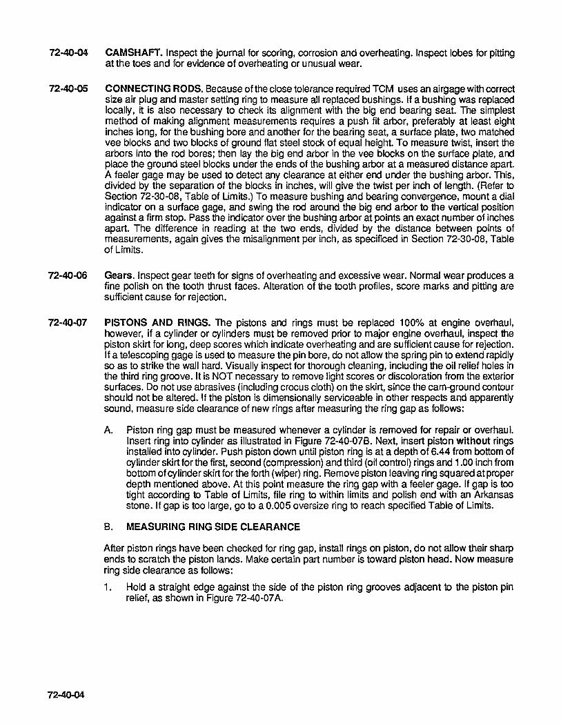
72-40-04 CAMSHAFT. Inspect the journal for scoring, corrosion and overheating. Inspect lobes for pitting at the toes and for evidence of overheating or unusual wear.
72-40-05 CONNECTING RODS. Because of the close tolerance required TCM uses an airgage with correct size air plug and master setting ring to measure all replaced bushings. If a bushing was replaced locally, it is also necessary to check its alignment with the big end bearing seat. The simplest method of making alignment measurements requires a push fit arbor, preferably at least eight inches long, for the bushing bore and another for the bearing seat, a surface plate, two matched vee blocks and two blocks of ground flat steel stock of equal height. To measure twist, insert the arbors into the rod bores; then lay the big end arbor in the vee blocks on the surface plate, and place the ground steel blocks under the ends of the bushing arbor at a measured distance apart. A feeler gage may be used to detect any clearance at either end under the bushing arbor. This, divided by the separation of the blocks in inches, will give the twist per inch of length. (Refer to Section 72-30-08, Table of Umits.) To measure bushing and bearing convergence, mount a dial indicator on a surface gage, and swing the rod around the big end arbor to the vertical position against a firm stop. Pass the indicator over the bushing arbor at points an exact number of inches apart. The difference in reading at the two ends, divided by the distance between points of measurements, again gives the misalignment per inch, as specificed in Section 72-30-08, Table of Limits.
72-40-06 Gears. Inspect gear teeth for signs of overheating and excessive wear. Normal wear produces a fine polish on the tooth thrust faces. Alteration of the tooth profiles, score marks and pitting are sufficient cause for rejection.
72-40-07 PISTONS AND RINGS. The pistons and rings must be replaced 100% at engine overhaul, however, if a cylinder or cylinders must be removed prior to major engine overhaul, inspect the piston skirt for long, deep scores which indicate overheating and are sufficient cause for rejection. If a telescoping gage is used to measure the pin bore, do not allow the spring pin to extend rapidly so as to strike the wall hard. Visually inspect for thorough cleaning, including the oil relief holes in the third ring groove. It is NOT necessary to remove light scores or discoloration from the exterior surfaces. Do not use abrasives (including crocus cloth) on the skirt, since the cam-ground contour should not be altered. If the piston is dimensionally serviceable in other respects and apparently sound, measure side clearance of new rings after measuring the ring gap as follows:
72-40-04
A. Piston ring gap must be measured whenever a cylinder is removed for repair or overhaul. Insert ring into cylinder as illustrated in Figure 72.,40-078. Next, insert piston without rings installed into cylinder. Push piston down until piston ring is at a depth of 6.44 from bottom of cylinder skirt for the first, second (compression) and third (oil control) rings and 1.00 inch from bottom of cylinder skirt for the forth (wiper) ring. Remove piston leaving ring squared at proper depth mentioned above. At this point measure the ring gap with a feeler gage. If gap is too tight according to Table of Limits, file ring to within limits and polish end with an Arkansas stone. If gap is too large, go to a 0.005 oversize ring to reach specified Table of Limits.
B. MEASURING RING SIDE CLEARANCE
After piston rings have been checked for ring gap, install rings on piston, do not allow their sharp ends to scratch the piston lands. Make certain part number is toward piston head. Now measure ring side clearance as follows:
1. Hold a straight edge against the side of the piston ring grooves adjacent to the piston pin relief, as shown in Figure 72-40-07 A.

FIGURE 72-40-07A INSPECTING RING SIDE CLEARANCE.
FIGURE 72-40-078 MEASURING RING GAP IN CYLINDER.
2. Turn piston rings until the gap of each ring is 90 degrees from the straight edge.
3. Push lightly on the piston ring, on the side opposite the straight edge, until ring is in contact with straight edge. Do not push the secured straight edge away from the piston.
4. Insert feeler gage, to approximately 1/8 inch depth, between top of piston ring and top of piston ring groove, next to straight edge. Check the Table of Limits for the approved side clearance dimension.
NOTE ... The piston rings must be replaced whenever the cylinder is honed.
72·40-05

72-40-08 CYLINDERS. Measure the barrel bore near the top of the ring travel limit and at the 5-114 station from the open end in the thrust direction at right angles to that in order to detect out-of-roundness and wear-in taper (See Figure 72-20-15 for dimensional inspection). There should be little or no wear at the open end. Look for bent barrel fins and broken head fins. Barrel fins can be straightened if not badly bent or cracked. No more than a 10% total reduction of head fin area is allowed. Look for cracked head fins, small radial cracks may be repaired by drilling a vee notch to remove. If a radial crack extends to the root of a fin it may have penetrated the wall; hence, the cylinder must be rejected.
If the cylinder base nuts were loose at disassembly, or if the base studs were loose or bent, test the machined side of the cylinder flange for bending, which is cause for rejection.
Measure valve guides for wear, and look for scoring in their bores. Valve seats must be inspected after refacing to make sure that there outside diameters are still less than the valve head diameters. Exhaust valves should be checked for warpage before refacing, and all valves must be measured in length if the stem tips were ground.
Inspect the spark plug hole and intake flange screw hole helical coil inserts for looseness, deformation and position. The outer ends should lie in the first full thread of the tapped holes in which they are installed. The spark plug hole helical coil has teeth at the outer end which are forced into the head metal and should not be visible.
If there was any evidence of overheating of cylinder or piston, check for possible turning of the head in relation to the barrel flange. Security between cylinder head and barrel is dependent on metal to metal contact of cylinder barrel top threads within the head shoulder. Dark stains at this area on both new and rebarreled cylinders is generally due to emission of thread lubricant used at factory assembly of head to barrel.
Due to 10-550 engine series cylinder design, a persistent oil leak (not a sealing compound leak) may indicate the required pre-load at the head/barrel junction has been relieved and must be investigated for possible cylinder replaqement (See TCM Service Bulletin M69-7 or current revision as applicable).
NOTE ... Due to the choke specified for the cylinder barrel bore, a cam-controlled grinder is required to regrind worn barrels to the maximum allowable 0.015 inch oversize dimension.
CAUTION .. . Magnaflux cylinder barrel and penetrate inspect the cylinder head each time the cylinder is removed from the engine.
72-40-09 HYDRAULIC VALVE TAPPETS.The hydraulic valve tappets must be replaced 100% at engine overhau I. However if tappets are suspect of malfunction prior to engine overhaul they may be removed and examined. During examination of each part, look for sludge and carbon residues. Also check for obstructed oil holes. Inspect face of cam follower on body for any type of damage and look for deep scoring and corrosion on exterior or tubular portion. Discard any tappet body which exhibits any of these faults. To test roughly for excessive diametrical clearance between hydraulic unit plunger and cylinder to check valve wear in cylinder, start dry plunger into dry cylinder. While holding cylinder between thumb and middle finger, depress plunger with index finger and release it quickly. Compression of air in cylinder should make plunger kick back instantly. If plunger does not return fully, either it is excessively worn or check valve is leaking. To check for leaking valve, repeat compression test while plugging end of oil inlet tube with other hand.
72-40-06
If plunger still does not kick back promptly, it and the cylinder are excessively worn. If it does kick back on the second test, either check valve seat is worn and leaking or it is dirty. Clean cylinder again and repeat first test (tube open). If plunger still does not kick back, valve is malfunctioning,. Upon completion of rough test the Hydraulic tappet should be checked for leakdown using Borroughs BT60C or compatible lifter tester. Valve leakdown ratio is as follows: Time 4 to 8 Seconds, Travel.125" Under 50 lbs. Load, Fluid PS1008, Viscosity 33 at 100· F. Any unit failing either of these test must be discarded and replaced. Discard both plunger and cylinder, since these parts are selectively fitted and are not interchangeable.

72-40·10 INTAKE TUBES. Inspect intake tubes for distortion, cracks and out-of-roundness. All other types of damage will require replacement of the part as well.
72-40-11 LUBRICATION SYSTEM. Visually inspect all parts of the system in accordance with the instructions in Sections 72-30-03, 07 & 09.
72-40·12 FUEL INJECTION SYSTEM. Further disassembly of the fuel injection system is not recommended unless proper flow equipment is available. For complete overhaul instructions, see Fuel Injection Overhaul Manual and Parts Catalog, Form X30593A.
72-40·13 IGNITION SYSTEM.
A. Teledyne Continental Motors recommends replacement of the complete ignition harness at every engine overhaul. If between major engine overhaul, repairs can be accomplished according to Chapter 74.
B. Magnetos should be disassembled and inspected at each 500 hour interval according to Magneto Service Manual.
SPARK PLUGS (See Figure 72-40-13).
CAUTlON ... Engine operation with worn spark plugs will cause ignition system malfunction.
Teledyne Continental Motors' aircraft engines utilize the two spark plug per cylinder configuration to provide a more efficient fuel/air mixture combustion and a safety feature in the event that one-half of the combined dual ignition system fails to operate due to adverse conditions. Two basic type spark plugs are used -- fine wire and massive electrode. Check the current spark plug service bulletin for the correct plug to engine application. Spark plugs should be removed, cleaned, inspected, gapped or replaced if found to be defective at each 100 hour interval. (See Figure 72-40-13, Spark Plugs). As spark plugs are removed, they should be marked to indicate cylinder position for relating a particular plug to any cylinder that may possibly have a serious cylinder,piston condition. When installing spark plugs, ensure that there is only one gasket and install in reverse as per Reverse Spark Plug installation procedure, (72-40-13B). Screw spark plug into cylinder by hand to within one or two threads of gasket. If resistance is encountered, check threads for misalignment and cleanliness. Torque to 25-30 foot pounds, or 300-360 inch pounds.
72-40-07

72-40-14
72-40-08
Normal Insulator tip gray tan or light brown. Few combustion deposits. Electrodes not burned or eroded. Proper type and heat range for the engine and service. The spark plug should be cleaned, regapped and tested before reinstallation.
Worn Out Normal Corrosive gases formed by combustion and the high voltage spark have eroded the electrodes. Spark plugs in this condition require more voltage to fire - often more than the ignition system can produce.
Worn Out Severe Excessive eroded center and ground electrodes and extensive necking of fine wire ground electrodes indicate abnormal engine power operation. Check fuel metering and magneto timing. Discard the plugs and before installing new spark plugs a careful check should be made to determine if proper heat range plugs are being used.
FIGURE 72-40-13A SPARK PLUGS.
Reduce wear of spark plug electrodes; due to constant polarity, either negative or positive, by reversing bottom (B) spark plugs with top (T) spark plugs per chart.
CYL. No. 1 T -TO-2 8 -TO~
3 T -TO-4 8 -TO-5 T -TO-6 8 -TO-
FIGURE 72-40-138 REVERSE SPARK PLUG INSTALLATION PROCEDURE
CYL. N • 6 8 5 T 4 8 3 T 2 8
-T
EXHAUST SYSTEM. For cleaning and inspection procedure pertaining to 10-550 D, E F & L exhaust systems refer to the appropriate airframe manufacturer's instructions.
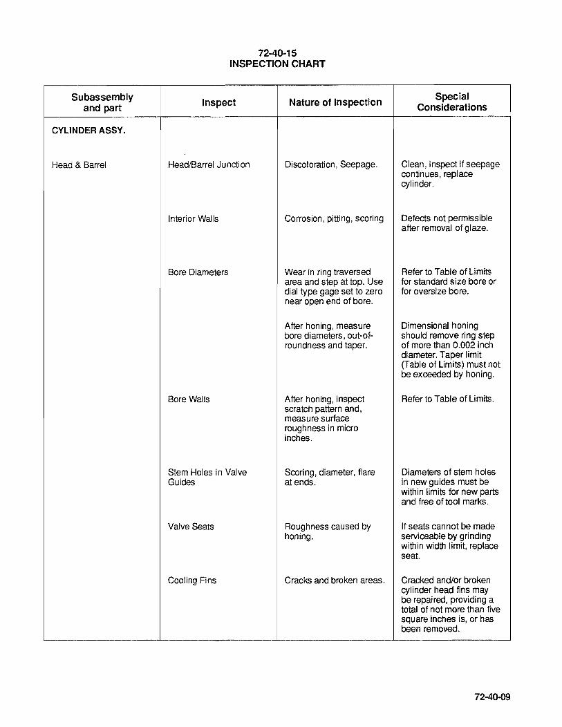
Subassembly and part
CYLINDER ASSY.
Head & Barrel
72-40-15 INSPECTION CHART
Inspect Nature of Inspection
Head/Barrel Junction Discoloration, Seepage.
Interior Walls Corrosion, pitting, scoring
Bore Diameters Wear in ring traversed area and step at top. Use dial type gage set to zero near open end of bore.
After honing, measure bore diameters, out-of-roundness and taper.
Bore Walls After honing, inspect scratch pattern and, measure surface roughness in micro inches.
Stem Holes in Valve Scoring, diameter, flare Guides at ends.
Valve Seats Roughness caused by honing.
Cooling Fins Cracks and broken areas.
Special Considerations
Clean, inspect if seepage continues, replace cylinder.
Defects not permissible after removal of glaze.
Refer to Table of Limits for standard size bore or for oversize bore.
Dimensional honing should remove ring step of more than 0.002 inch diameter. Taper limit (Table of Limits) must not be exceeded by honing.
Refer to Table of Limits.
Diameters of stem holes in new guides must be within limits for new parts and free of tool marks.
If seats cannot be made serviceable by grinding within width limit, replace seat.
Cracked and/or broken cylinder head fins may be repaired, providing a total of not more than five square inches is, or has been removed.
72-40-09

72-40-15. INSPECTION CHART (Continued).
Subassembly and part
Valve Rockers
Rocker Shaft
CONNECTING ROD ASSEMBLY
Bushing
72-40-10
Inspect
Base Flange
Pilot
Spark Plug Thread Insert
Pushrod Housing Stems
Valve Stems
Valve Heads
Valve Length
Contact Foot
Oil Passages
Hub
Outside Surface
Inside Diameter
Nature of Inspection
If attaching nuts were found loose at disassembly, test for flatness of mounting face.
Out-of-roundness of pilot below face flange.
Distortion or improper fit in cylinder head hole.
Looseness, leakage.
Scoring, nicks in grooves, wear on tips.
Use dial indicator to determine warp. Make sure that grinding has not exceeded specified limits.
Use height gage to detect stretch and check for reduction due to tip grinding.
Wear.
Obstruction.
Special Considerations
Allow not over 0.001 inch out-of-flat on machined surface.
Polishing must not reduce diameter below minimum for new parts.
Stretched or shortened valve may exceed ability of hydraulic tappets to take up lash, or exceed normal operating clearances.
Side clearance between Refer to Table of Limits. cylinder head supports.
Diameter, scoring, rough ends
Measure using air gauge with correct size air plug and master setting ring.
New bushings must be reamed or bored within diameter limits for new parts. Sharp edges must be broken slightly. (Refer to Table of Limits, for wear limits, new bushing limits and alignments.)
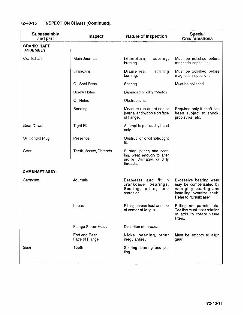
72-40-15 INSPECTION CHART (Continued).
Subassembly and part
CRANKSHAFT ASSEMBLY
Crankshaft
Gear Dowel
Oil Control Plug
Gear
CAMSHAFT ASSY.
Camshaft
Gear
Inspect
Main Journals
Crankpins
Oil Seal Race
Screw Holes
Oil Holes
Bending
Tight Fit
Presence
Teeth, Screw, Threads
Journals
Lobes
Flange Screw Holes
End and Rear Face of Flange
Teeth
Nature of Inspection Special Considerations
Diameters, burning.
scoring, Must be polished before magnetic inspection.
Diameters, burning.
scoring Must be polished before magnetic inspection.
Scoring.
Damaged or dirty threads.
Obstructions.
Measure run-out at center journal and wobble on face of flange.
Attempt to pull out by hand only.
Obstruction of oil hole, tight fit.
Burring, pitting and scoring, wear enough to alter profile. Damaged or dirty threads.
Diameter and fit in crankcase bearings. Scoring, pitting and corrosion.
Pitting across heel and toe at center of length.
Distortion of threads.
Nicks, peening, other irregularities.
Scoring, burring and pitting.
Must be polished.
Required only if shaft has been subject to shock, prop strike, etc.
Excessive bearing wear may be compensated by enlarging bearing and installing oversize shaft. Refer to "Crankcase".
Pitting not permissible. Toe line must taper relation of axis to rotate valve lifters.
Must be smooth to align gear.

72-40-15. INSPECTION CHART (Continued).
Subassembly Inspect Nature of Inspection Special and part Considerations
CRANKCASE ASSEMBLY
Crankcase Valve Tappet Diameter, Scoring Castings Guides
Bearing Seals Roughness, wear in tang Refer to Table of Limits notches.
Camshaft Diameter, scoring, fit of Bearings rear bearing between
camshaft flanges.
Oil Passages Inspect visually, galleries, main and camshaft bearing supply holes, using inspector's flashlight to illuminate. Probe other oil holes with brass rod.
Tapped Holes Deformed or dirty threads.
Studs Threads Distortion.
Height Check for backing outs. Refer to Stud Height Table.
Squareness Use toolmaker'S square to Refer to Stud HeightTable. check studs suspected of bending.
Idler Gear Support and Bore Inside diameter, scoring. Refer to Table of Limits. Bushings
Needle Bearing Rollers Roughness or excessive play.
Retainer Mounting Surface Oil Seal Warpage, cracks. Observe that old seal has been removed without damage to retainer.
Oil Filler Neck Tightness, leakage Attempt to rock and puli out Must be tight in castings. by hand only.
Oil Gage Rod Distortion Look for bent blade, obliterated "FULL" and "LOW" marks, loose collar, deformed cap.
Plugs Threads Look for distortion.
Wrench Flats Look for damaged corners.
72-40-12

72-40-15. iNSPECTION CHART
Subassembly Inspect Nature of Inspection Special and part Considerations
OIL COOLER ASSY.
Oil Cooler Headers, Fins, Core Inspect visually for dents, deformed fins, puntures, stripped plug hole threads, cracks, scratches and chafing.
Machined Surfaces Warpage and scratches.
All Areas Cracks.
Oil Temperature Seat Roughness Control Valve
OIL SUMP ASSY.
Casting Tapped Holes Damaged threads, cracks around holes.
Mounting Surfaces Scratches, warpage, cracks.
All Areas Cracks.
Plugs Threads Look for distortion.
Wrench Flats Look for damaged corners.
Oil Suction Tube Threads, Tube Filter Damaged threads, dented tube, cracks in tube, distorted or plugged filter.
Oil Screen Mesh Broken screen.
Engine Mounting Brackets Machined Surfaces Scratches, cracks.
OIL PUMP ASSY.
Housing All Areas Cracks, scratches on machined surfaces, restrictions in oil holes.
Gearshaft Look for scoring, measure Gears must turn freely. diameter. (Refer to Table of Limits.)
Plugs Distorted threads, damaged wrenching surfaces.
72·40-13
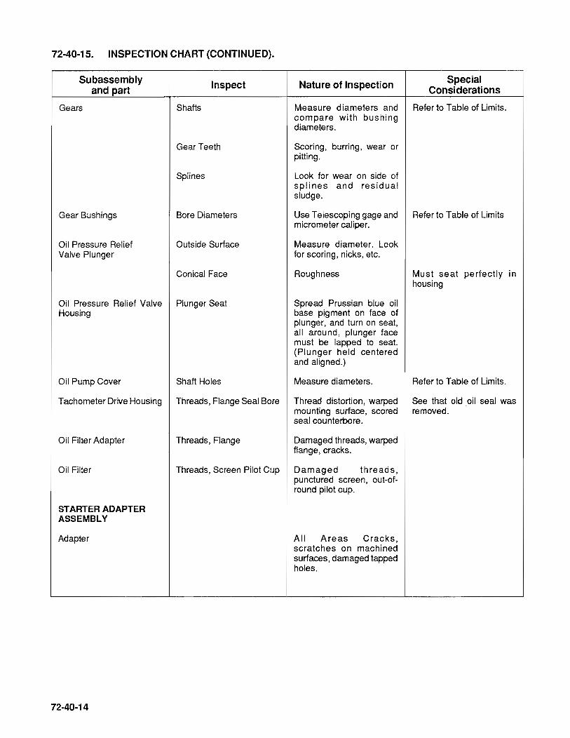
72-40-15. INSPECTION CHART (CONTINUED).
Subassembly and part
Gears
Gear Bushings
Oil Pressure Relief Valve Plunger
Inspect
Shafts
Gear Teeth
Splines
Bore Diameters
Outside Surface
Conical Face
Oil Pressure Relief Valve Plunger Seat Housing
Nature of Inspection
Measure diameters and compare with bushing diameters.
Scoring, burring, wear or pitting.
Look for wear on side of splines and residual sludge.
Special Considerations
Refer to Table of Limits.
Use Telescoping gage and Refer to Table of Limits micrometer caliper.
Measure diameter. Look for scoring, nicks, etc.
Roughness
Spread Prussian blue oil base pigment on face of plunger, and turn on seat, all around, plunger face must be lapped to seat. (Plunger held centered and aligned.)
Must seat perfectly in housing
Oil Pump Cover Shaft Holes Measure diameters. Refer to Table of Limits.
Tachometer Drive Housing Threads, Flange Seal Bore Thread distortion, warped See that old oil seal was
Oil Filter Adapter
Oil Filter
STARTER ADAPTER ASSEMBLY
Adapter
72-40-14
mounting surface, scored removed. seal counterbore.
Threads, Flange Damaged threads, warped flange, cracks.
Threads, Screen Pilot Cup Damaged threads, punctured screen, out-ofround pilot cup.
All Areas Cracks, scratches on machined surfaces, damaged tapped holes.
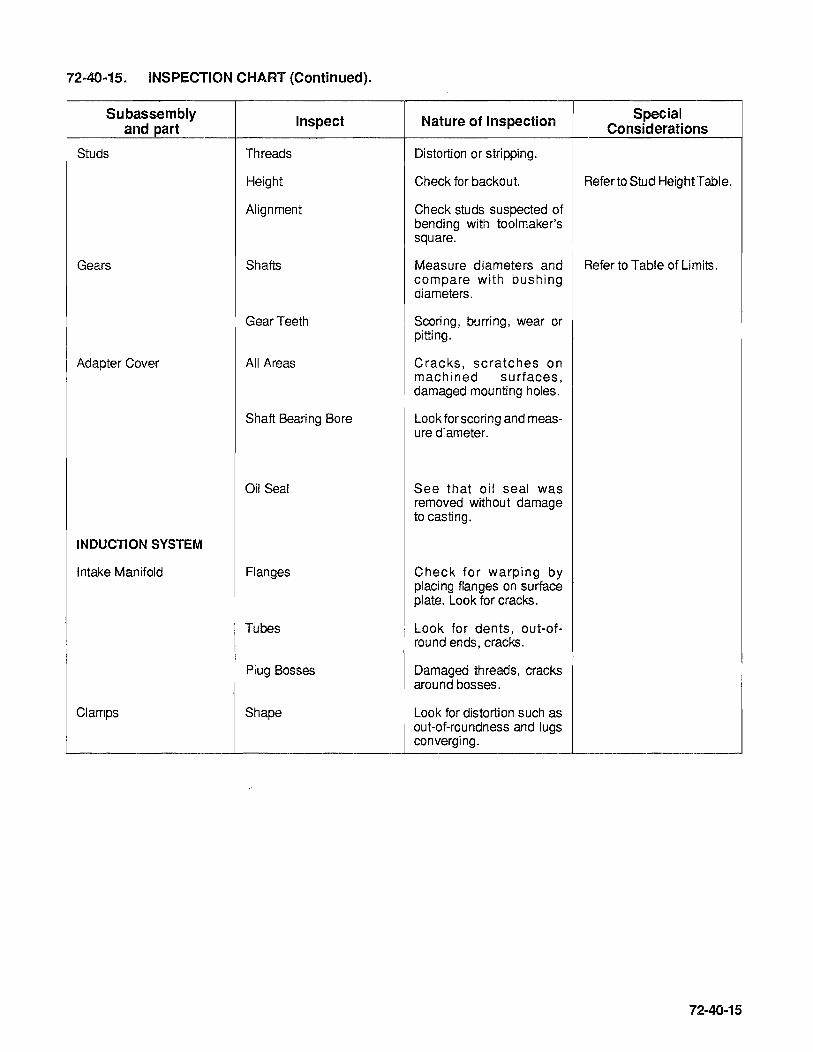
72-40-15. INSPECTION CHART (Continued).
Subassembly Inspect Nature of Inspection Special and part Considerations
Studs Threads Distortion or stripping.
Height Check for backout. Refer to Stud HeightTable.
Alignment Check studs suspected of bending with toolmaker's square.
Gears Shafts Measure diameters and Refer to Table of Limits. compare with bushing diameters.
Gear Teeth Scoring, burring, wear or pitting.
Adapter Cover All Areas Cracks, scratches on I machined surfaces,
damaged mounting holes.
Shaft Bearing Bore Look for scoring and meas-ure diameter.
Oil Seal See that oil seal was removed without damage to casting.
INDUCTION SYSTEM
Intake Manifold Flanges Check for warping by placing flanges on surface plate. Look for cracks.
Tubes Look for dents, out-of-round ends, cracks.
Plug Bosses Damaged threads, cracks around bosses.
Clamps Shape Look for distortion such as out-of-roundness and lugs converging.
72-40-15
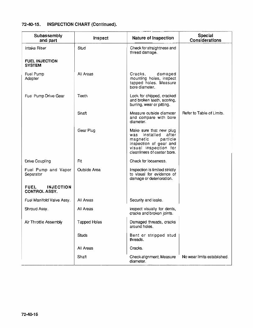
72-40-15. INSPECTION CHART (Continued).
Subassembly and part
Intake Riser
FUEL INJECTION SYSTEM
Fuel Pump Adapter
Fuel Pump Drive Gear
Inspect
Stud
All Areas
Teeth
Shaft
Gear Plug
Drive Coupling Fit
Fuel Pump and Vapor Outside Area Separator
FUEL INJECTION CONTROL ASSY.
Fuel Manifold Valve Assy. All Areas
Shroud Assy. All Areas
Air Throttle Assembly Tapped Holes
Studs
All Areas
Shaft
72-40-16
Nature of Inspection
Check for straightness and thread damage.
Cracks, damaged mounting holes, inspect tapped holes. Measure bore diameter.
Look for chipped, cracked and broken teeth, scoring, burring, wear or pitting.
Special Considerations
Measure outside diameter Refer to Table of Limits. and compare with bore diameter.
Make sure that new plug was installed after magnetic particle inspection of gear and visual inspection for cleanliness of center bore.
Check for looseness.
Inspection is limited strictly to visual for evidence of damage or deterioration.
Security and leaks.
Inspect visually for dents, cracks and broken jOints.
Damaged threads, cracks around holes.
Bent or stripped stud threads.
Cracks.
Check alignment. Measure No wear limits established. diameter.

72-40-15. INSPECTION CHART (Continued).
Subassembly Inspect Nature of Inspection Special and part Considerations
Plate Check for warpage.
Fuel Discharge Tubes All Areas Look for cracks, flat spots, out-of-round ends.
Pipe Fittings Threads Distortion or stripping.
Wrench Flats Look for damaged corners.
MAGNETO AND ACCESSORY DRIVE ASSEMBLY
Adapter Gear Bushing Measure bore diameters. Refer to Table of Limits.
Oil Seal Observe that old seal has been removed without damage to casting bore.
Studs Look for stripped and deformed threads.
Gear Teeth Scori ng, bu rri ng, wear or pitting.
Shaft Measure diameters and Refer to Table of Limits. compare with bushing diameter.
72-40-17

72·40·18
INTENTIONALL Y
LEFT
BLANK

SECTION 72~50 ASSEMBLY OF SUBASSEMBLIES
72-50-00 72-50-01
72-50-02
72-50-03
72-50-04
72-50-05
72-50-06
72-50-07
72-50-08
72-50-09
72-50-10
72-50-11
72.:50-12
72-50-13
ASSEMBLYOFSUBASSEMBUES General
Oil Pump Assembly
Starter and Drive Assembly
Cylinder Assembly
Piston and Ring Assemblies
Pushrod Housing
Crankshaft and Connecting Rods
Camshaft
Crankcase
Fuel Pump
Fuel Control Valve
Fuel Manifold Valve
Fuel Control Valve and Throttle Assembly
72-50-01

72-50-02
INTENTIONALL Y
LEFT
BLANK
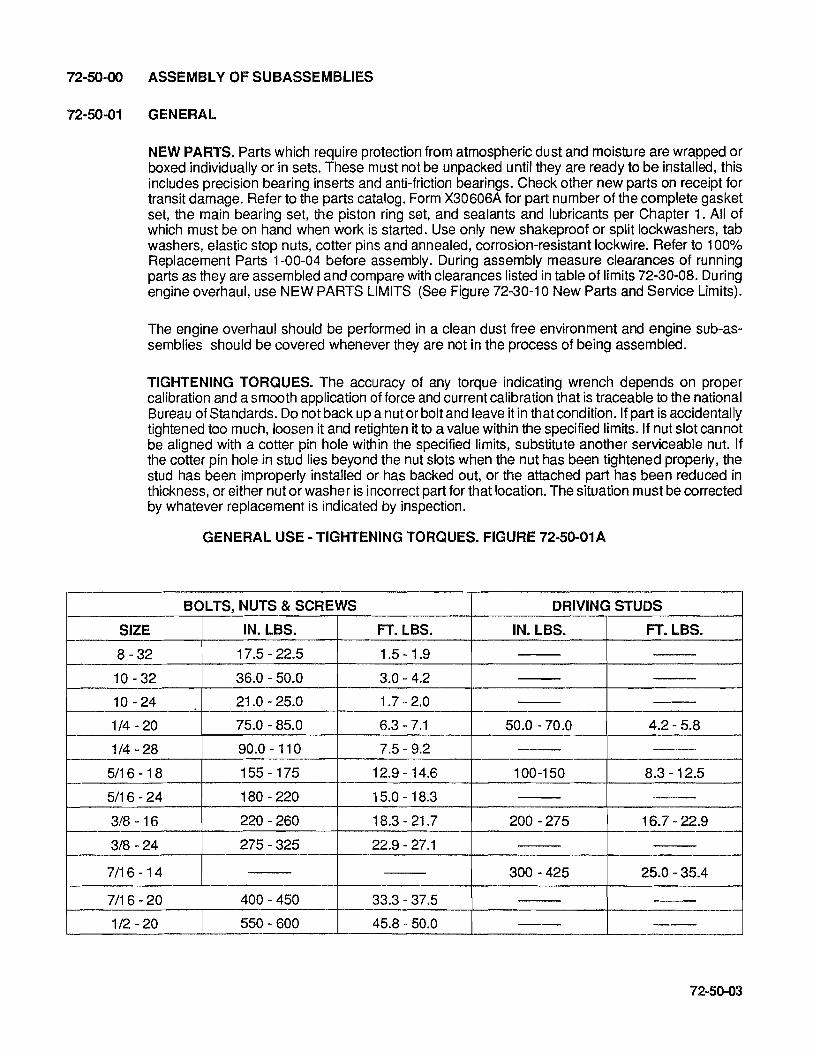
72-50-00 ASSEMBLY OF SUBASSEMBLIES
72-50-01 GENERAL
NEW PARTS. Parts which require protection from atmospheric dust and moisture are wrapped or boxed individually or in sets. These must not be unpacked until they are ready to be installed, this includes precision bearing inserts and anti-friction bearings. Check other new parts on receipt for transit damage. Refer to the parts catalog. Form X30606A for part number of the complete gasket set, the main bearing set, the piston ring set, and sealants and lubricants per Chapter 1. All of which must be on hand when work is started. Use only new shakeproof or split lockwashers, tab washers, elastic stop nuts, cotter pins and annealed, corrosion-resistant lockwire. Refer to 100% Replacement Parts 1-00-04 before assembly. During assembly measure clearances of running parts as they are assembled and compare with clearances listed in table of limits 72-30-08. During engine overhaul, use NEW PARTS LIMITS (See Figure 72-30-10 New Parts and Service Limits).
The engine overhaul should be performed in a clean dust free environment and engine sub-assemblies should be covered whenever they are not in the process of being assembled.
TIGHTENING TORQUES. The accuracy of any torque indicating wrench depends on proper calibration and a smooth application of force and current calibration that is traceable to the national Bureau of Standards. Do not back up a nut or bolt and leave it in that condition. If part is accidentally tightened too much, loosen it and retighten it to a value within the specified limits. If nut slot cannot be aligned with a cotter pin hole within the specified limits, substitute another serviceable nut. If the cotter pin hole in stud lies beyond the nut slots when the nut has been tightened properly, the stud has been improperly installed or has backed out, or the attached part has been reduced in thickness, or either nut or washer is incorrect part for that location. The situation must be corrected by whatever replacement is indicated by inspection.
GENERAL USE - TIGHTENING TORQUES. FIGURE 72-50-01 A
BOLTS, NUTS & SCREWS DRIVING STUDS
SIZE IN. LBS. FT. LBS. IN. LBS. FT. LBS.
8 - 32 17.5 - 22.5 1.5 - 1.9
10 -32 36.0 - 50.0 3.0 - 4.2
10 - 24 21.0 - 25.0 1.7 - 2.0
1/4 - 20 75.0 - 85.0 6.3-7.1 50.0 -70.0 4.2 - 5.8
1/4 - 28 90.0 - 110 7.5 - 9.2
5/16 -18 155 -175 12.9 -14.6 100-150 8.3 -12.5
5/16 - 24 180 - 220 15.0 -18.3
3/8 -16 220 - 260 18.3 - 21.7 200 - 275 16.7 - 22.9
3/8 - 24 275 - 325 22.9 - 27.1
7/16-14 300 - 425 25.0 - 35.4
7/16 - 20 400 - 450 33.3 - 37.5
1/2 - 20 550 - 600 45.8 - 50.0
72-50-03

TABLE OF TIGHTENING TORQUES 72-50-01 B
(J) LOCATION & MODEL SIZE HARDWARE
Oil Pump Housing To Nut 10-550 D & F .25 - 28
Crankcase Nut 10-550 E & L .25 - 28
Right Angle Tach Drive Nut 10-550 D & F .25 - 28
Cover-To-Oil Pump Nut 10-550 E & F .25 - 28
Oil Pressure Relief Valve Housing ALL 1.12-18
Housing
10-550 D, F & Housing L .875 - 18
Housing Tach Drive Nut 10-550 E .25 - 28
Screw 10-550 E 10-24 X .50
Oil Filter 10-550 D & F 1.75-16 Oil Filter Assy.
Oil Filter 10-550 E & L .75 - 16
Oil By-Pass Assy. Pin & Plug 10-550 D & F .875 - 16 X .62
Plug 10-550 E & L .125 - 27
Oil Pump Housing Plug 10-550 E & L .50 - 14
NPTF
Starter Adapter-to-Nut ALL .31 - 24
Crankcase
Bolt ALL .31-18 X 2.81
Starter Adapter & Cover- Bolt ALL .31-18 X to-Crankcase 3.0625
Bolt ALL .31-18X 1 .125
Starter Gear-to-Clutch Screw ALL .25-20X.406 Spring Special
Starter Shaftgear Nut ALL .5625-18
Sheave
Starter-to-Adapter Nut .ALL .375 - 24
Rocker Shaft Set Screw ALL .3125-24X.53
Cylinder-to-Crankcase Nut ALL .44-20
Rocker Cover-to-Cylinder Screw ALL .25-20X.75
Gear-to-Crankshaft Bolt ALL .31-24X8.75
(Hardness Rc 38-42)
(continued on next page) *Footnotes are located on page 72-50-07.
72-50-04
QTY
8
7
2
3
1
1
4
4
1
1
1
1
1
2
1
3
2
1
1
2
12
42
48
6
CD TORQUE
IN.LBS. FT. LBS.
90.0 -110 7.5 - 9.2
90.0 - 110 7.5 - 9.2
90.0 - 110 7.5 - 9.2
90.0 - 110 7.5 - 9.2
240 - 260 20.0 - 21.7
No Torque Hand Tighten & Snug with Wrench
90.0 - 110 7.5 - 9.2
21.0 - 25.0 1.7 - 2.0
500 - 520 41.6 - 43.3
216 - 240 18.0 - 20.0
190 - 210 15.8 - 17.5
60 -80 5.0 - 6.7
255 - 285 21.3 - 23.8
180 - 220 15.0 - 18.3
155 - 175 12.9 - 14.6
155 - 175 12.9 - 14.6
155-175 12.9-14.6
75.0-85.0 6.3-7.1
450-500 37.5-41.7
200-220 16.7-18.3
85-110 7.1-9.2
490-510 40.8-42.5
45-55 3.8-4.6
380-420 31.7-35.0
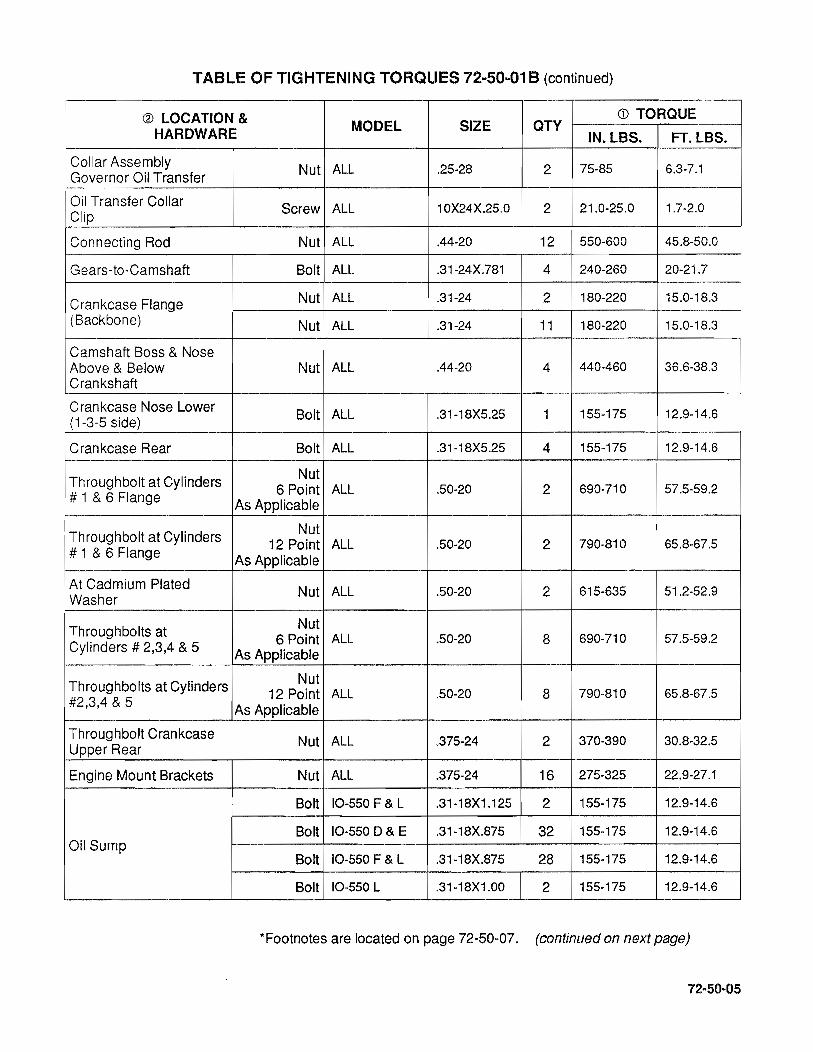
TABLE OF TIGHTENING TORQUES 72-50-01 B (continued)
@ LOCATION & <D TORQUE MODEL SIZE aTY HARDWARE IN.LBS. FT. LBS.
Collar Assembly Nut ALL .25-28 2 75-85 6.3-7.1
Governor Oil Transfer
Oil Transfer Collar Screw ALL 10X24X.25.0 2 21.0-25.0 1.7-2.0
Clip
Connecting Rod Nut ALL .44-20 12 550-600 45.8-50.0
Gears-to-Camshaft Bolt ALL .31-24X.781 4 240-260 20-21.7
Crankcase Flange Nut ALL .31-24 2 180-220 15.0-18.3
(Backbone) Nut ALL .31-24 11 180-220 15.0-18.3
Camshaft Boss & Nose Above & Below Nut ALL .44-20 4 440-460 36.6-38.3 Crankshaft
Crankcase Nose Lower Bolt ALL .31-18X5.25 1 155-175 12.9-14.6
(1-3-5 side)
Crankcase Rear Bolt ALL .31-18X5.25 4 155-175 12.9-14.6
Throughbolt at Cylinders Nut 6 Point ALL .50-20 2 690-710 57.5-59.2
# 1 & 6 Flange As Applicable
Throughbolt at Cylinders Nut 12 Point ALL .50-20 2 790-810 65.8-67.5
# 1 & 6 Flange As Applicable
At Cadmium Plated Nut ALL .50-20 2 615-635 51.2-52.9
Washer
Throughbolts at Nut 6 Point ALL .50-20 8 690-710 57.5-59.2
Cylinders # 2,3,4 & 5 As Applicable
Throughbolts at Cylinders Nut 12 Point ALL .50-20 8 790-810 65.8-67.5
#2,3,4 & 5 As Applicable
Throughbolt Crankcase Nut ALL .375-24 2 370-390 30.8-32.5
Upper Rear
Engine Mount Brackets Nut ALL .375-24 16 275-325 22.9-27.1
Bolt 10-550 F & L .31-18X1.125 2 155-175 12.9-14.6
Bolt 10-550 D & E .31-18X.875 32 155-175 12.9-14.6 Oil Sump
Bolt 10-550 F & L .31-18X.875 28 155-175 12.9-14.6
Bolt 10-550 L .31-18X1.00 2 155-175 12.9-14.6
*Footnotes are located on page 72-50-07. (continued on next page)
72-50-05
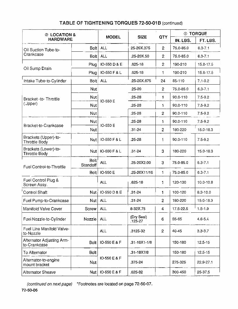
TABLE OF TIGHTENING TORQUES 72-50-01 B (continued)
@ LOCATION & HARDWARE MODEL SIZE
Oil Suction Tube-to- Bolt ALL 25-20X.375
Crankcase Bolt ALL .25-20X.50
Plug 10-550 D & E .625-18 Oil Sump Drain
Plug 10-550 F & L .625-18
Intake Tube-to-Cylinder Bolt ALL .25-20X.875
Nut .25-20
Bracket -to- Throttle Nut .25-28
(Upper) 10-550 E
Nut .25-28
Nut .25-28
Nut .25-28 Bracket-to-Crankcase 10-550 E
Nut .31-24
Brackets (Upper)-to-Nut 10-550 F & L .25-28
Throttle Body
Brackets (Lower)-to-Nut 10-550 F & L .31-24
Throttle Body
Bolt ALL .25-20X2.00 Fuel Control-to-Throttle Standoff
Bolt 10-550 E .25-20X11/16
Fuel Control Plug & ALL .625-18
Screen Assy.
Control Shaft Nut 10-550 D & E .31-24
Fuel Pump-to-Crankcase Nut ALL .31-24
Manifold Valve Cover Screw ALL 8-32X.75
Fuel Nozzle-to-Cylinder Nozzle ALL (Dry Seal) .125-27
Fuel Line Manifold Valve- ALL .3125-32 to-Nozzle
Alternator Adjusting Arm-Bolt 10-550 E & F .31-18X1-1/8
to-Crankcase
To Alternator Bolt .31-18X7/8
Alternator-to-engine 10-550 E & F
mount bracket Nut .375-24
Alternator Sheave Nut 10-550 E & F .625-32
(continued on next page) *Footnotes are located on page 72-50-07.
72-50-06
CD TORQUE QTY
IN.LBS. FT. LBS.
2 75.0-85.0 6.3-7.1
2 75.0-85.0 6.3-7.1
2 190-210 15.8-17.5
1 190-210 15.8-17.5
24 85-110 7.1-9.2
2 75.0-85.0 6.3-7.1
1 90.0-110 7.5-9.2
1 90.0-110 7.5-9.2
2 90.0-110 7.5-9.2
1 90.0-110 7.5-9.2
2 180-220 15.0-18.3
1 90.0-110 7.5-9.2
3 180-220 15.0-18.3
3 75.0-85.0 6.3-7.1
1 75.0-85.0 6.3-7.1
1 120-130 10.0-10.8
1 100-120 8.3-10.0
2 180-220 15.0-18.3
4 17.5-22.5 1.5-1.9
6 55-65 4.6-5.4
2 40-45 3.3-3.7
150-180 12.5-15
150-180 12.5-15
275-325 22.9-27.1
300-450 25-37.5

TABLE OF TIGHTENING TORQUES 72-50-01 B -
@ LOCATION & CD TORQUE MODEL SIZE OTY HARDWARE IN.LBS. FT. LBS.
Acessory Drive Adapter- Nut ALL .375-24 2 275-325 22.9-27.1
to-Crankcase Nut ALL .31-24 6 180-220 15.0-18.3
Accessory Drive Adapter Nut ALL .25-28 8 90-110 7.5-9.2 Cover
Oil Cooler Adapter Plate- Nut 10-550 D,E & F .25-28 5 90-110 7.5-9.2
to-Crankcase Nut 10-550 L .25-.28 3 90-110 7.5-9.2
Oil Cooler-to-Adapter Bolt 10-550 D,E & F .25-20X1.375 12 100-110 8.3-9.2
Oil Temperature Control 10-550 D, E & 1 "-14NS3A- 1 440-460 36.7-38.3 Valve-to-Adapter Plate F THD
Oil Temperature Control 10-550 L 1.25-18 1 640-660 53.3-55 Valve-to-Crankcase
Plug, Special-to- 10-550 D,E & F 1.25-18 1 640-660 53.3-55 Crankcase
Magneto-to-Crankcase Nut ALL .31-24 4 100-120 8.3-10
Spark Plug ALL 18MM 12 300-360 25-30
Nut S1200 Series 10-32 4 17-19 1.4-1.6 Harness Plate-to-Magneto Screw S20 & S200 10-32 4 25-35 2.1-2.9 Series
Ignition Lead "B" Nut-to-ALL .75-20 12 110-120 9.2-10.0 Spark Plug
Oil Seal Retainer-to- Bolt 10-550 D,F & L 10-24X.38 4 21-25 1.7-2.1 Crankcase
Pin Idler Gear Support Nut ALL .25-28 2 90-110 7.5-9.2 Stud
Neck Oil Filler Screw ALL .25-20X.50 3 75-85.0 6.3-7.1
CD Torque loads listed are for use with oil on threads. If cotter pin holes must be aligned, set torque wrench at low limit and tighten nut to first hole beyond this torque, except for connecting rods. Stud driving torques apply when studs are coated with lubricant or sealer.
@ Hardware requiring torque, not listed should be torqued according to general use Tightening Torque Chart or Pipe Plugs and Hydraulic line Fitting charts as applicable.
72-50-07
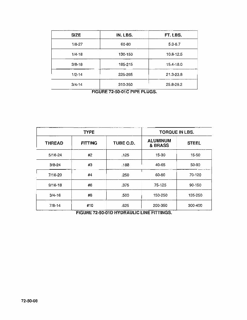
SIZE IN. LBS. FT. LBS.
1/8-27 60-80 5.0-6.7
1/4-18 130-150 10.8-12.5
3/8-18 185-215 15.4-18.0
1/2-14 225-285 21.3-23.8
3/4-14 310-350 25.8-29.2
FIGURE 72-50-01 C PIPE PLUGS.
TYPE TORQUE IN LBS.
THREAD FITTING TUBEO.D. ALUMINUM STEEL & BRASS
5/16-24 #2 .125 15-30 15-50
3/8-24 #3 .188 40-65 50-90
7/16-20 #4 .250 60-80 70-120
9/16-18 #6 .375 75-125 90-150
3/4-16 #8 .500 150-250 135-250
7/8-14 #10 .625 200-350 300-400
FIGURE 72-50-01 D HYDRAULIC LINE FITTINGS.
72-50-08
72-50-02A OIL PUMP ASSEMBLY 10-550-0 & F (See Figure 72-10-13A).
A. Install new gasket (35) on By-pass Valve (36), coat by-pass valve threads with TCM PIN 646943 anti-seize lubricant. Install by-pass valve assembly (33 thru 36) into oil pump housing (2). Assemble pressure relief valve housing (13) and adjusting screw (11), turn adjusting screw into housing until 13/16 inch of screw shows above housing. Secure adjusting screw using copper washer (15) and nut (16). Assemble plunger (8) spring (9) washer (10) and slide into oil pump housing. Install new gasket (12) on pressure relief valve housing and coat housing threads with anti-seize lubricant TCM PIN 646943. Insure that adjusting screw aligns with plunger, spring, washer and screw relief valve housing into oil pump housing. Torque to values given in Table of Tightening Torques 72-50-01.
B. Install new gasket (25) on oil filter (26). Coat oil filter threads with TCM PIN 646943 anti-seize lubricant. Screw oil filter assembly into oil pump housing. Torque to value given in Table of Tightening Torques 72-50-01.
C. Using clean 50 wt. aviation engine oil lubricate and install pump drive and driven gears (7 & 17) into oil pump housing, place bevel gear (19) on end of oil pump drive gear (17).
D. Install a new oil seal (24) in tach drive housing (23) at this time.
E. Using two sets of attaching hardware (37, 38, 39) attach oil pump cover assembly (20) to housing. Do not tighten at this time. Store oil pump assembly in a clean dust free area until final assembly.
72-50-02B OIL PUMP ASSEMBLY 10-550-E & L (See Figure 72-10-13B)
A. Coat threads of plug (7) with TCM PIN 646943 anti-seize lubricant and install in housing (2). Assemble pressure relief valve housing (15) and adjusting screw (13), turn adjusting screw into housing until 13/16 inch of screw shows above housing. Secure adjusting screw using copper washer (17) and nut (18). Assemble plunger (10), spring (11), washer (12), and slide into oil pump housing. Install new gasket (14) on pressure relief valve housing and coat housing threads with anti-seize lubricant TCM PIN 646943. Ensure that adjusting screw aligns with plunger, spring, washer and screw relief valve housing into oil pump housing. Torque to values given Table of Tightening Torques 72-50-01 .
B. Oil filter should be installed during final assembly. Using clean 50 wt. engine oilliubricate and install pump drive and driven gears (8, 19) into oil pump housing, bevel gear (21) will be installed at final assembly.
C. On IO-550-E engines a new oil seal (28) should be installed in oil pump coverltach drive housing (27) at this time.
On IO-550-L engines a new oil seal (24) should be installed in tach drive housing (23) at this time.
D. Using three sets of attaching hardware (41,42 & 43) attach oil pump cover assembly (22 or 27) as applicable to oil pump housing. Do not tighten at this time store oil pump in a clean dust free area until final assembly.
72-50-09

72-50-03 STARTER AND DRIVE ASSEMBLY (See Figure 72-10-12).
A. Install needle bearing (8) in adapter (6).
B. Press bearing (13) onto worm shaft (12) until seated against flange. Install spring (10), Woodruff key (11) and worm gear (9). Insert assembly into adapter and install retaining ring (14).
C. Install clutch spring (17) on worm wheel (16). Turn spring so it tends to unwind until offset end drops into gear hub groove. Position spring on gear so screw notch is aligned with screw hole in gear web. Install tab washer (18) and screw (19). Torque screw (28) to value shown in Table of Tightening Torques 72-50-01 and bend tab against screw head.
D. Lubricate spring, sleeve and shaftgear liberally with clean oil. Press worm wheel and spring assembly onto shaftgear (15). Install "0" ring (21) on shaft (15). Insert shaftgear and worm wheel assembly into adapter. Make sure worm wheel and worm gear teeth are aligned.
E. Compress and install retaining ring (25) in cover (23). Press in ball bearing (24) and new oil seal (26), with seal lips toward retaining ring. Insert sleeve (22) into seal.
F. Install gasket (20) and cover assembly on adapter and secure with attaching parts (27, 28, 29).
G. Install sheave (31) and secure with attaching parts (32, 33, 34). Torque sheave nut to value given in Table of Tightening Torques 72-50-01.
72-50-04 CYLINDER ASSEMBLY (See Figure 72-10-14).
72-50-10
Each cylinder should have its position number (1 thru 6) stamped on edge of base flange. After disassembly, cylinders should be laid on a bench in order of position number. Place piston, pin and ring assemblies in front of each cylinder in the same order. Piston number will be towards propeller flange. Mark any new cylinder and/or piston accordingly.
A. Spread a film of "Moly shield" grease on valve stems (11, 12) and insert them in cylinders to which they have been lapped. Grasp valve stems and lift cylinder onto a post which will support valve heads. Clamp cylinder base flange to prevent it from rising. Again apply "Molyshield" to valve stems.
B. Place valve spring retainers (15) over valve guide (5), cupped side up. Install seals (16) onto intake valve guides (4). Install inner and outer valve springs (13, 14), per illustration Figure 72-50-04, and roto coils (16). Compress springs and install keys (17). Make certain keys are properly seated before releasing pressure on springs. Remove cylinder from fixture and set it upright on a bench. Strike end of each valve stem sharply with a rawhide mallet to set stem keys. After valve mechanism has been assembled check valve spring height according to dimensions given in Table of Limits Section 72-30-08.
C. Install new packing (1) on each cylinder skirt. Push against flange and make certain none are twisted. Coat cylinder bore walls thoroughly with clean Grade 50 MHS 27 oil.
NOTE ... Valve rocker arm shafts should be installed and temporarily secured with proper hardware before cylinder installation. Store cylinder assemblies in a clean dust free area until final assembly.

SPRING·VALVE. INNER SPRING·VALVE. OUTER
RETAINER VALVE GUIDE
INSERT
INSTALLED -iooI-----=..WoI(
SPRING HEIGHT
SEE DIMENSIONS IN TABLE OF LIMITS
NOTE: • INNER AND OUTER SPRINGS MUST BE INSTALLED AS SHOWN. WITH CLOSED COILS TOWARD CYLINDER HEAD.
FIGURE 72-50-04 VALVE SPRING INSTALLATION
72-50-05 PISTON AND RING ASSEMBLIES (See Figure 72-10-14).
A. Lubricate piston (45) and rings (46 thru 49) liberally with clean Grade 50 MHS 27 oil.
B. Position first and third ring gaps on the top of piston. Position second and fourth ring gaps so they will be 180· apart from first and third ring gaps, as applicable.
72-50-06 PUSH ROD HOUSING (See Figure 72-10-14).
A. Install a washer (36), packing (37) and washer (36) on cylinder end of housings (35).
B. Install spring (38), washer (36), packing (37) and washer (36) onto crankcase end of housing (35).
72-50-11
72·50-07 CRANKSHAFT AND CONNECTING RODS (See Figure 72·10-17).
72-50-12
NOTE ... Before assembly crankshaft should be checked for remaining magnetism from inspection procedures, if found demagnetize.
NOTE ... Refer to 100% replacement parts 1-00-04 before assembly.
A. Lay crankshaft on bench with a notched wood block under front and rear journals.
B. Attach two sixth order counterweights (16) to crankcheek no. 2 with two pins (13) each and install retaining plates and rings (12, 11). Install retaining rings with the flat or rough side to the outside, be sure that retaining rings seat in their respective lands properly. Attach one fourth order and one fifth order counterweight to crankcheek no. 5. Install pins (14, 15) secure with retaining plates, rings (12, 11) using same procedure as stated above.
Do not mix pins in the same counterweight.
C. Lubricate oil control collar (19,20) with clean Grade 50 Aviation oil and install on crankshaft. Use new pins (23) secure with new nuts (18). Tighten nuts (18) alternately in 20" LB. increments to torque value given in Table of Tightening Torques 72-50-01. Care must be taken in assembling the collar to crankshaft because of the close running clearance involved. The collar should rotate freely to prevent frictional heating. Check for a running clearance of .0005L to .0018 between collar and crankshaft this will insure good oil pressure to propeller.
O. Heat crankshaft gear (25) to 300· F., use thick gloves to prevent burning hands and install gear on crankshaft, align gear dowel hole with crankshaft dowel (30) this should properly position gear so that timing marks are in line with the no. 2 throw when at TOC to achieve proper timing between crankshaft and camshaft. USing a rawhide mallet tap gear onto crankshaft. Attach gear to crankshaft using six new bolts (24). Torque bolts to value given in Table of Tightening Torques 72-50-01. Safety wire bolt heads (see Chapter 70 Standard Practices).
E. Layout connecting rods, caps, new bolts and nuts (5 thru 8) opposite their respective crankpins according to poSition numbers stamped on connecting rod bolt bosses. Install new bearing insert in each rod and cap, make sure their ends project the same distance and they are properly seated.
F. Using clean 50 wt. Aviation oil, lubricate and install each rod and cap with numbers on top when odd number rods are extended to the right and even number rods are to the left viewing crankshaft from the rear (gear end) forward. Secure rods and caps using new special bolts and nuts (6, 5). Tighten to value given in Table of Tightening Torques 72-50-01.
G. Remove spring (26) and reinforcing ring (27) from oil seal (28). Unhook spring ends using an unwinding motion. Wrap spring around shaft in seal area, turn spring ends in an unwinding motion, wrap spring around shaft in seal area, turn spring ends in an unwinding direction then join and allow one end to wind into the other end. Apply Alvania (Shell #2) to lip of oil seal and prop flange only. Squeeze oil seal until egg shaped and start over flange. A special tool is available from Borrough's Tool and Equipment Company to assist in seal installation PIN 5209 (See Section 1-20-00 item 71 ). After seal is on the shaft, wipe grease from oil seal and shaft. The 0.0. of the seal is to be dry when installed in the crankcase. No sealing cement or compound is to be used. Install the reinforcing ring, work 0.0. of seal over ring to insure a snug fit. Install spring in cavity in seal.

72-50-08 CAMSHAFT
A. Install the camshaft in a suitable holding fixture, using rawhide mallet tap new Woodruff Key (3) into groove on camshaft, tap governor drive gear onto camshaft.
B. Install gear (6) and cam cluster gear (5). Bolt holes are off-set to assure proper positioning for timing. Install four new bolts (4). Torque to value given in Table of Tightening Torques 72-50-01. Safety wire bolt heads (see Chapter 70 Standard Practices).
72-50-09 Crankcase (See Figure 72-10-15).
A. Apply loctite pipe sealant with teflon (PSfT) sparingly on pipe plug male threads only. Replace all pipe plugs that were removed to pressure flush crankcase halves. Torque to values given in Table of Tightening Torques 72-50-01. Make sure oil dilution plug (71) is re-safety wired (see Standard Practices Chapter (70).
B. Install new o-ring (28), gasket (27) on special plug (26) or oil temperature control valve (26) as applicable. Install plug or valve (26) in right crankcase halve, torque to value given in Table of Tightening Torques 72-50-01 and safety wire (see Chapter 70 Standard Practices).
WARNING ... Use the proper installation tool so as not to damage bearing.
C. Install new needle bearing (66) with PIN facing outward into right crankcase half. Press bearing into case to a depth of .20 to .21. (See Figure 72-50-09).
D. If oil gage housing extention (65) was removed during disassembly re-install. Outer edge of extension should extend 1.25 inch from crankcase. Install hose (12) on extension and secure with one clamp (10).
NEEDLE BEARING ----., (PRESS IN PLACE
TO DEPTH SHOWN) .20 .21
FIGURE 72-50-09 NEEDLE BEARING INSTALLATION
72-50-13
E. Install new gasket (17) and oil filter neck (16), secure with attaching hardware (15). Install new gasket (34) and cover (33), if installing propeller governor refer to airframe manufacturers installation instructions secure with attaching hardware (29 thru 32). Torque to value given in table of tightening torques 72-50-01.
F. Install engine mount brackets (63), secure using attaching hardware (61 ,62). Torque to value given in table of tightening torques 72-50-01. Lay crankcase halves open side up, using clean 50 wt. Aviation engine oil lubricate all camshaft bearings and crankshaft main bearing bosses. Install crankshaft bearings (2) Figure 72-10-17, apply clean 50 wt. aviation engine oil to crankcase thrust washer lands to prevent thrust washer from falling out during final assembly. Install thrust washer halves (1) Figure 72-10-17, insure bearings seat properly and bearing ends project equally. Lubricate bearings with clean 50 wt. Aviation engine oil.
G. Install new oil transfer clip (73) secure with screws (82). Torque screws to value given in table of tightening torques 72-50-01 and safety wire screw heads (see Chapter 70-1 0 - Standard Practices.). Insure that safety wire is trimmed and positioned so that the oil transfer collar will rest flush and even against the collar clip (73) to prevent costly damage to oil transfer collar and crankshaft.
FUEL INJECTION SYSTEMS.
NOTE ... The fuel injection component fittings should be screwed into proper size holes in a block of soft wood after flushing with solvent to reduce the likelihood of burrs or foreign particles entering the system.
72-50-10 FUEL PUMP (See Figures 72-50-10 A & B).
72-50-14
NOTE ... Before proceeding, fuel pump should be new, factory overhauled or overhauled and tested per instructions given in TCM Form X30593A.
CAUTION .. . Proper test equipment must be available for overhaul of TCM Fuel Injection Components.
A. Position fuel pump shroud on fuel pump. Install all fittings and position them in their proper location per chart on illustrations 72-50-10 A & B. Apply TCM PIN 646940 Fuel Injection Sealant sparingly on tapered pipe, male threads of fittings only.
CAUTION .. . Never use teflon tape on fuel injection component fittings. Store fuel pump in clean, dust free area until final assembly.

72-50-11 FUEL CONTROL VALVE (See Figure 72-50-11)
NOTE ... Before proceeding, fuel control valve should be new, factory overhauled or overhauled and tested per instructions given in TCM Form X30593A.
CAUTION ... Proper test equipment must be available for overhaul of TCM Fuel Injection components.
A. Install all fittings and position them in their proper location per chart on illustration 72-50-11. Apply TCM 646940 Fuel Injection Sealant sparingly on tapered pipe male threads of fitting only.
CAUTION ... Never use teflon tape on fuel injection component fittings. Store fuel control valve in a clean, dust free area until fuel control valve and throttle assembly.
72-50-12 FUEL MANIFOLD VALVE (See Figure 72-50-12)
NOTE ... Before proceeding, manifold valve should be new, factory overhauled or overhauled and tested per instructions given in TCM Form X30593A.
CAUTlON ... Proper test equipment must be available for overhaul of TCM fuel injection components.
A. Install all fittings and position them in their proper locations per chart on illustration 72-50-12. Apply TCM 646940 Fuel Injection Sealant sparingly on tapered pipe male threads of fittings only.
CAUTION ... Never use teflon tape on fuel injection component fittings. Store manifold valve in a clean, dust free area until final assembly.
72·50·15

MODEL
10-550-0
72·50·16
"E" FITTING
o· "A" FITTING
/ O·
90'270.90' .~'-~ ~ ----
r--""'I:'--""~
180'
270~'
~90' 180'
"B" FITTING "O"FITTING
-I-c~+-+-90'
FIGURE 72-50-10A FUEL PUMP FITTING ORIENTATION.
"A" INLET liB" OUTLET "e"MIXTURE "0" VAPOR
FiniNG FITTING RETURN RETURN FITTING FITTING
90' ELBOW 125' NIPPLE 90' ELBOW 270' 45' ELBOW 225" 45' ELBOW 180' 90' ELBOW 180'
liE" SEAL DRAIN FITTING
NIPPLE
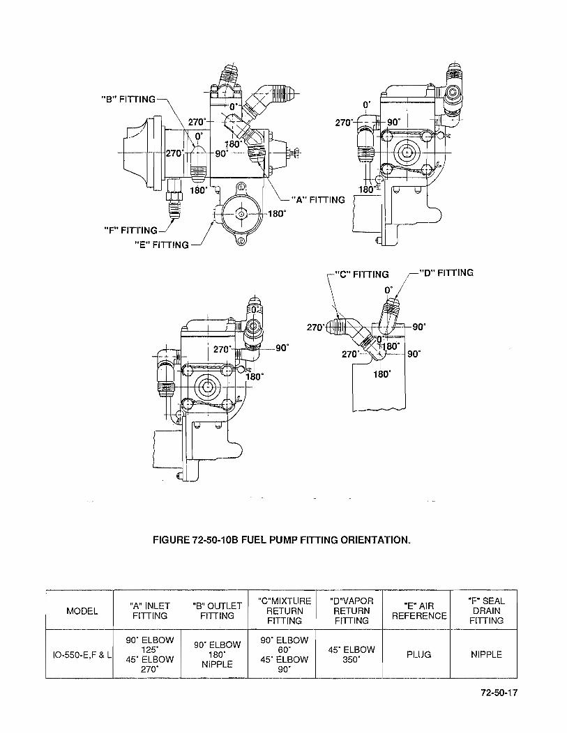
"8" FITTING
270·
"A" FITTING
"F" FITTING I "E" FITTING ~
;-"0" FITTING
270· +HHHIljllf--'>,;~++ 90·
90·
180·
FIGURE 72-50-108 FUEL PUMP FiniNG ORIENTATION.
"A" INLET "B" OUTLET "C"MIXTURE "D"VAPOR "E" AIR
"F" SEAL MODEL FITTING FITTING RETURN RETURN
REFERENCE DRAIN FITTING FITTING FITTING
90' ELBOW 90· ELBOW 90· ELBOW
IO-550-E,F & L 125·
180· 60' 45· ELBOW PLUG NIPPLE 45· ELBOW 45· ELBOW 350·
270· NIPPLE 90·
72·50·17
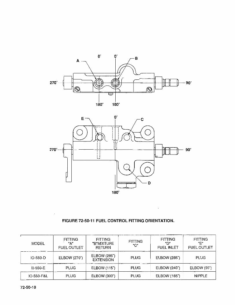
MODEL
IO-550-D
10-550-E
IO-550-F&L
72-50-18
0' A
0' B
270' ---+I---++------i* -n-t--Iltl )i1J-+----i----+t----i+tt-*--t+- 90'
180' 180'
0' C
270'---l1l---t+-----i-i----I I I I I I
'----.---U-----t1~I==~ 90'
" L..J
180'
FIGURE 72-50-11 FUEL CONTROL FiniNG ORIENTATION.
FITTING FITTING FiniNG FiniNG "A" "B"MIXTURE "CO "0"
FUEL OUTLET RETURN FUEL INLET
ELBOW (270') ELBOW (285') PLUG ELBOW (285') EXTENSION
PLUG ELBOW (115') PLUG ELBOW (240')
PLUG ELBOW (300') PLUG ELBOW (165')
FITTING "E"
FUEL OUTLET
PLUG
ELBOW (90')
NIPPLE

"C" Fittings
-:+-+---+- 90·
~~-90·
2250 1350
1800
225" 135· A
C~--~--+----4-
COVER ORIENTATION
B
FIGURE 72-50-12 MANIFOLD VALVE FITTING ORIENTATION.
MODEL "A" FITTING "B"FITIING "G" FITTING
IO-550-D,E,F&L 45· ELBOW @ 270· 90" ELBOW @ 270' 90" ELBOW @ 135"
72-50-19

72-50-13 FUEL CONTROL VALVE AND THROTTLE ASSEMBLY (See Figures 72-10-06A,B,&C).
72-50-20
A. 10-550-0 (See Figures 72-10-06A).
1. Place the control unit (7) under air throttle body (6): Attach with three tab washers (10) and stand-off bolts (11). Tighten bolts to torque specified in Table of Tightening Torques, 72-50-01 . Bend ear of tab washer to flat side of hex head on bolt.
2. Place wave washer (17) on link rod (12) and insert into throttle lever: Then install washer (18) and cotter pin (19).
3. Slide spring (14) and rod end (15) onto link rod (12): Then attach elastic stop nut (16) to link rod. Place wave washer (17) on rod end (15) and insert rod end into control lever. Secure with washer (9) and cotter pin (19). Final adjustment of rod linkage will be established at final assembly.
4. Lubricate all fuel injection linkage using Shell #5 MIL-G-3545C.
B. 10-550-E (See Figure 72-10-06B).
1. Position control unit (7) against throttle body (6) and attach with tab washers (10) and stand-off bolts (11). Tighten bolts and bend ear of tab washer to flat side of hex head on bolt.
2. Place wave washer (17) on link rod (12) and insert into throttle lever: Then secure with washer (18) and cotter pin (19).
3. Slide spring (14) and rod end (15) onto link rod (12): Then attach elastic stop nut (16) to link rod. Place wave washer (17) on rod and insert rod end into control unit lever. Secure with washer (18) and cotter pin (19). Final adjustment will be established at final assembly.
4. Lubricate all fuel injection linkage using Shell #5 MIL-G-3545C.
C. 10-550-F & L (See Figure 72-10-06C).
1. Assemble control unit (7) to air throttle body (6) with tab washers (11) and stand-off bolts (12). Tighten bolts and bend ear of tab washers to flat side of hex head on bolt.
2. Slide spring (14) and rod end (15) onto link rod (13) and attach elastic stop nut (16). Place wave washer (17) on rod end (15) and insert rod end into control unit lever. Secure with washer (18) and cotter pin (19). Final adjustment will be established at final assembly.
3. Lubricate all fuel injection linkage using Shell #5 MIL-G-3545C.
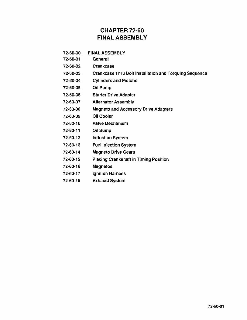
72-60-00 72-60-01
72-60-02
72-60-03
72-60-04
72-60-05
72-60-06
72-60-07
72-60-08
72-60-09
72-60-10
72-60-11
72-60-12
72-60-13
72-60-14
72-60-15
72-60-16
72-60-17
72-60-18
CHAPTER 72~60 FINAL ASSEMBLY
FINAL ASSEMBLY General
Crankcase
Crankcase Thru Bolt Installation and Torquing Sequence
Cylinders and Pistons
Oil Pump
Starter Drive Adapter
Alternator Assembly
Magneto and Accessory Drive Adapters
Oil Cooler
Valve Mechanism
Oil Sump
Induction System
Fuel Injection System
Magneto Drive Gears
Placing Crankshaft in Timing Position
Magnetos
Ignition Harness
Exhaust System
72-60-01

72-60-02
INTENTIONALL Y
LEFT
BLANK
72-60-00 FINAL ASSEMBLY
72-60-01 GENERAL. Apply clean 50 wt. Aviation Engine Oil liberally to all bare steel surfaces, journals bearings and bushings., before and after installation depending on accessibility, except where special lubricants are mentioned (See Table of Sealants and Lubricants Chapter 1-30).
During assembly, measure clearances of running parts as they are installed and compare with clearances listed in Table of Limits 72-30-08. During engine overhaul, use New Parts Limits (see 72-30-10 New Parts and Service Limits). Also TCM requires that certain parts be replaced 100% at overhaul (See 1-00-04 100% Replacement Parts).
TCM requires that engine overhaul be performed in a clean, dust free environment and that openings be covered as soon as possible to prevent admittance of foreign debris or small parts to the engine.
WARNING ... Oil pressure is applied to the face of the accessory drive pads.
72-60-02 CRANKCASE (See Figures 72-10-15).
A. Install the left crankcase half on engine stand and support engine case with a prop. A length of pipe or wood with case end protected by something soft such as rubber or plenty of masking tape wrapped around it, may be used. (See Figure 72-60-02A).
B. Check to make sure that crankshaft bearings (2) and thrust washer halves (1) are still seated properly, that their ends project equally and they are well lubricated with clean 50 wt. Aviation Engine Oil. I nstall new o-rings (23) on oil transfer sleeve (22) figure 72-10-17, lubricate and install sleeve in case. With the aid of an assistant, lift crankshaft assembly by No. 1 connecting rod and propeller flange, have assistant hold No.3 & 5 connecting rods upward, carefully lower assembly into position in left crankcase bearings with oil seal positioned so it enters the seal cavity in the case half. Position oil transfer collar so it seats properly on oil transfer sleeve. The connecting rod position numbers, if properly installed, will be toward the upper case flange. Carefully lay odd numbered rods on the upper case flange. Check thrust washers and bearings to insure they are still properly poSitioned.
C. Using clean 50 wt. Aviation Engine Oil lubricate governor driven gear shaft (1) figure 72-10-16 and its bearing surface in case half. Install governor driven gear.
D. Re-Iubricate camshaft bearing surfaces with clean 50 wt. Aviation Engine Oil and lubricate camshaft lobes with dow corning molycoat G-N Paste, install camshaft so that crankshaft gear and camshaft gear timing marks align as gears mesh. No. 1 connecting rod on crankshaft should be in fully extended (TDC) position. Governor driven gear may have to be turned slightly to allow camshaft to seat in bearings properly. Check governor driven gear backlash and compare with tolerance given in Table of Limits, use only new parts limits (See 72-30-10 New Parts & Service Limits).
E. Measure crankshaft end clearance using either a feeler gage or a dial indicator set at zero against the propeller flange. Measure camshaft end clearance at either end of its rear main bearing. (See Section 72-30-08 Table of Limits for allowable tolerances).
72-60-03

FIGURE 72·60-02A LEFT CRANKCASE AND SHAFTS ASSEMBLED ON STAND.
1. Crankshaft Gear Timing Marks 2. Camshaft Gear Timing Mark
FIGURE 72·60-028 ALIGNMENT OF TIMING MARKS.
72-60-04

F. Using clean 50 wt. Aviation Engine, lubricate idler gear bushing (4), (Figure 72-10-17) and idler gear support pin (37), (Figure 72-1 0-15).
NOTE ... The support pin eccentric shoulder must be away from crankshaft.
Using a new gasket (38), (Figure 72-10-15) install idler gear assembly and support pin in left crankcase, with idler gear bushing thrust flange to the rear. Using a dial indicator check idler, cam and crankshaft gear backlash. Compare with tolerances given in Table of Limits 72-30-08. Use only New Parts Limits, (see 72-30-10 New Parts and Service Limits).
G. Apply sealants and thread to crankcase halves per instructions outlined in section 70-20-00 crankcase sealant and threading procedure.
H. Stand odd numbered connecting rods straight up, have assistant balance and guide connecting rods through 1-3-5 case half cylinder openings as it is installed and back idler gear support pin out partially to clear studs.
I. Lay 1-3-5 (right) crankcase half on 2-4-6 (left) case half. Take care to prevent displacement or damage to the crankshaft oil seal, governor oil transfer sleeve o-rings, idler gear and support pin gasket. Ensure that thrust washer halves and bearings remain in place. Push idler gear support pin back onto studs. Install support pin attaching hardware (35, 36) (Figure 72-10-15), but do not tighten at this time.
FIGURE 72-60-02C lEFT SIDE OF COMPLETE CRANKCASE ON STAND.
72-60-05

72-60-03 CRANKCASE THRU-BOL T INSTALLATION AND TORQUING SEQUENCE.
72-60-06
°
CAUTION ... AII studs and thru bolt threads to be lubricated per Table of Sealants and Lubricants Section 1-30-00.
56 56 o
39 52 50 48' 46' 45 47 49 51 53 53 51 49 ,47 ,45 ,4648 50 52 39 54 0 \!::) ,g. ,g. '0 \9' '0 '0 \9t e.. 55 57
\9-34 36 14 16 5 7 \9-
3°8BO 32 10 12 180 0 3 1~B ~ 58 59 60
CYL. #1 0 CYL. 113 0 CYL. #5 0 0
42 0 0 0027
0338 31 13 0 11 4 0 0 2 228 43 37 35 17 15 8 6 0 ° 038 180 9 0 290 40
57 55 .QJ & ~ -.g, -9" '\9' ~ ~ -9 54 ".Of
a 23 255 7 14 16
01981 1 0 310 28 0 61
o . CYl, #6 0 CYL #4 w 0
o 0 0 44 22A 20 4 0 2 13 0 0 11 '33A 29 Q) 26 24 90 8 6 180 17 15 038
FIGURE 72-60-03. TORQUING SEQUENCE
NOTE ... See Figure 72-10-15 for item identification and figure 72-60-03 for crankcase stud, thru bolt and hole positions.
A. Install two 7/16 X 8-7/8 inch thru bolts (56) in positions (27, 28) using new washers (48) and o-rings (49). Install 3/8 X 9-13/16 thru bolt (50) in position (39) using new washers (44, 45). Install two 5/16 X 5-1/4 tie bolts (43) in hole positions (40, 42, 43). Use new o-ring (46) on bolt in hole position (42).
B. Using new o-rings (58) install one 1/2 X 9-13/16 inch thru bolt (57) in position (19). Using new o-rings (58) install seven 1/2 X 10-3/4 inch thru bolts (59) in positions (1,4, 10, 13,22,30 & 33).
C. Install four 7/16 X 10-112 inchthru bolts (60) in positions (9, 18,29,38).
NOTE ... Tap all thru bolts with a non-marring hammer to a centered position. These bolts align crankcase castings and bearings.
D. Install and snug attaching hardware (39,40,47,48,.49) on thru bolts at positions (27,28 & 39). Snug tie bolts (43) at positions (40,42 & 43). This hardware will hold crankcase halves and internal mechanism together during assembly and torquing sequence.
NOTE ... Secure 1-3-5 side engine mounts to assembly stand. Rotate engine stand until engine is in upright position as shown in Figure 72-60-02C.
E. Place manifold valve assembly over crankcase backbone positions (45, 46). Install spacers (22, 25), lifting eye (24) at backbone positions (46, 48). Install two 5/16 X 1-23/32 bolts in backbone positions (45 & 46). Place washer on bolt at position (45) before installing. Secure with attaching hardware (18, 19, 20) and snug. Install remaining crankcase backbone hardware 5/16 X 1-15/32 bolts (55), washers (54 & 56), nuts (53) in crankcase backbone positions (47, 49 thru 57) and snug.
F. Install and snug attaching hardware (39, 40) on thru bolts (60) at positions (9, 18, 29, 38). On 2-4-6 side at nose just below crankshaft install a 5/16 plain washer (54), nut (53) and snug.
NOTE ... Proceed to cylinder installation procedure section 72-60-04.
G. After all cylinders have been installed, tighten nuts at positions (1 thru 8) to a preliminary torque of 350 inch pounds, tighten nuts at positions (10 thru 17) to a preliminary torque of 350 inch pounds, tighten nuts at poSitions (19 thru 26) to a preliminary torque of 350 inch pounds and tighten nuts at positions (30 thru 37) to a preliminary torque of 350 inch pounds.
H. Install seventh stud attaching hardware (5051 & 52) at positions (58 thru 63). Tighten to a preliminary torque of 350 inch pounds.
I. Torque nuts and bolts (1 thru 63) to Final Torque values below using Torquing Sequence Figure 72-60-03.
J. Repeat torquing sequence (1 thru 63) to insure that all nuts and bolts have been torqued to correct values.
CRANKCASE FINAL TORQUE VALUES
TORQUE IN. LBS. SEQUENCE NUMBER
690-710 (6 point nut see note) . . . . . . . . . . . . . . . . . . . . . . . . . .. 1,4, 10, 13 690-710 (6 point nut see note) ....................... 19A, 22A, 30B, 33B 615-635 . . . . . . . . . . . . . . . . . . . . . . . . . . . . . . . . . . . 19B, 22B, 30A, 33A 490-510 . 2,3,5 thru 8, 11, 12, 14 thru 17, 20, 21, 23 thru 26, 31, 32, 34 thru 37, 58 thru 63. 440-460 . . . . . . . . . . . . . . . 9, 18, 29, 38 180-220 . . . . . . .. ................... 45 thru 57 440-460 . . . . . . . . . . . . . . . . . . . . . . . . . . . 27, 28 370-390 . . . . . . .. . ...................... 39 155-175 . . . . . . .. ................ 40,41,42,43,44
NOTE ... Torque 5/16 nut on thru stud 2-4-6 side at nose just below crankshaft to 180-220 inch pounds.
NOTE ... Torque 12 point nuts when used on cylinderflange thru bolts to 790-81 0 inch pounds.
K. Torque idler gear support pin attaching hardware to values given in Table of Tightening Torques 72-50-01.
NOTE ... The following items will be found in Figure 72-10-15.
L. Using new gasket (80) install camshaft cover (81) and secure with attaching hardware (82, 83). Using new gasket (27) install special plug (26) on 10-550-0, E & F or oil temperature control valve (26) on IO-550-L. Install nose seal retainer plates (78) and secure with screws (79). Install oil gage housing (11) into extension hose. Secure with remaining clamp (1 O) and attaching hardware (4 thru 9). Torque hardware to values given in Table of Tightening Torques 72-50-01.
72-60..Q7
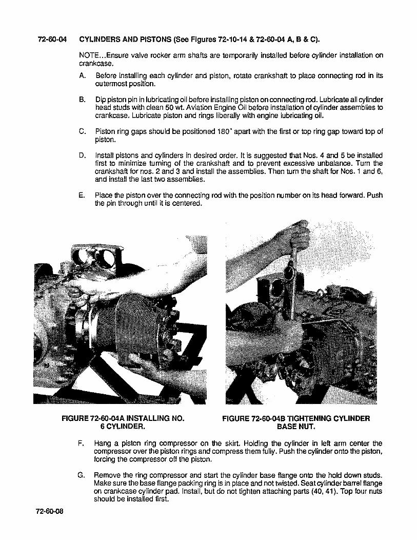
72-60-04 CYLINDERS AND PISTONS (See Figures 72-10-14 & 72-60-04 A, B & C).
NOTE ... Ensure valve rocker arm shafts are temporarily installed before cylinder installation on crankcase.
A. Before installing each cylinder and piston, rotate crankshaft to place connecting rod in its outermost position.
B. Dip piston pin in lubricating oil before installing piston on connecting rod. Lubricate all cylinder head studs with clean 50 wt. Aviation Engine Oil before installation of cylinder assemblies to crankcase. Lubricate piston and rings liberally with engine lubricating oil.
C. Piston ring gaps should be positioned 180· apart with the first or top ring gap toward top of piston.
D. Install pistons and cylinders in desired order. It is suggested that Nos. 4 and 5 be installed first to minimize turning of the crankshaft and to prevent excessive unbalance. Turn the crankshaft for nos. 2 and 3 and install the assemblies. Then turn the shaft for Nos. 1 and 6, and install the last two assemblies.
E. Place the piston over the connecting rod with the position number on its head forward. Push the pin through until it is centered.
FIGURE 72-60-04A INSTALLING NO. 6 CYLINDER.
FIGURE 72-60-04B TIGHTENING CYLINDER BASE NUT.
72-60-08
F. Hang a piston ring compressor on the skirt. Holding the cylinder in left arm center the compressor over the piston rings and compress them fully. Push the cylinder onto the piston, forcing the compressor off the piston.
G. Remove the ring compressor and start the cylinder base flange onto the hold down studs. Make sure the base flange packing ring is in place and not twisted. Seat cylinder barrel flange on crankcase cylinder pad. Install, but do not tighten attaching parts (40, 41). Top four nuts should be installed first.

®
FIGURE 72-6D-04C CYLINDER FLANGE TORQUE SEQUENCE FOR SINGLE
CYLINDER INSTALLATION.
FIGURE 72-60-05A OIL PUMP, FUEL PUMP AND STARTER ADAPTER INSTALLED.
H. Install spark plugs and gaskets in upper cylinder holes.
I. After installing all pistons and cylinders, return to Section 72-60-03 paragraph "G" to proceed.
72-60-05A OIL PUMP ASSEMBLY 10-55D-D & F (See Figure 72-1D-13A).
A. Remove attaching hardware (37,38,39) and oil pump cover assembly (20) from housing (2).
B. Spread a film of No.3 Aviation Permatex on rear cover flange of the oil pump.
1. Use full strength, non-thinned Permatex, aviation grade 3D. Shake or mix well before using.
2. Apply Permatex to the surface to be threaded, using short, light brush strokes until an even, thin coat is obtained. The Permatex should be viscous enough that most of the brush marks disappear, if not, use a new can of Permatex. (Allow to air dry to a tacky condition before threading).
3. Apply Permatex to all areas on pump cover (20) that will mate with pump housing threaded flange. Use same technique as above.
4. Apply silk thread TCM PIN 641653 to oil pump housing, position thread as shown in Figure 72-60-05B.
72-60-09

FIGURE 72-60-05B OIL PUMP THREADING DIAGRAM 10-550-0 & F.
FIGURE 72-60-05C OIL PUMP THREADING DIAGRAM 10-550-E & L.
C. Install oil pump cover (20) on oil pump housing studs carefully to prevent movement of silk thread. Secure with attaching hardware (37, 38, 39). Install tach drive shaft (21) into cover (20), insure that gears mesh properly. Install new gasket (22) on tach drive housing (23) and coat tach drive housing threads with TCM PIN 646943 anti-seize lubricant. Slide tach drive housing (23) over shaft (21) and screw into oil pump cover. Torque to value given in Table of Tightening Torques 72-50-01.
D. Install new gasket (1) on crankcase oil pump studs, slide oil pump assembly onto studs and secure with remaining attaching hardware (37,38,39). Torque to value given in Table of Tightening Torques 72-50-01.
72-60-058 OIL PUMP ASSEMBLY 10-550-E & L {See Figure 72-10-138}.
72-60-10
A. Remove attaching hardware (41 ,42,43) and oil pump cover assembly (22 or 27) as applicable from oil pump housing (2).
B. Spread a film of No.3 Aviation Permatex on rear cover flange of oil pump.
1. Use full strength, non-thinned Permatex, aviation grade 3 D. Shake or mix well before using.
2. Apply Permatex to the surface to be threaded using short light brush strokes until an even thin coat is obtained. The Permatex should be viscous enough that most of the brush marks disappear, if not use a new can of Permatex. (Allow to air dry to a tacky condition before threading).

3. Apply Permatex to all areas on pump cover (22 or 27) as applicable that will mate with pump housing threaded flange. Use same technique as above.
4. Apply silk thread TCM PIN 641653 to oil pump housing position thread as shown in figure 72-60-05C.
C. Install oil pump cover (22 or 27) as applicable, on oil pump housing studs carefully to prevent movement of silk thread. Secure with attaching hardware (41,42,43).
D. On IO-550-L, using clean 50 wt. Aviation Engine Oil lubricate and install tach drive shaft (25) into cover (22). Install new gasket (26) on tach drive housing (23) and coat tach drive housing threads with TCM PIN 646943 anti-seize lubricant. Slide tach drive housing (23) over shaft (25) and screw into oil pump cover. Torque to value given in Table of Tightening Torques 72-50-01.
E. On IO-550-E, using clean 50 wt. Aviation Engine Oil, lubricate and install bevel gear (21) through tach drive housing opening onto oil pump drive gear shaft. Lubricate and install tach drive shaft (30). Ensure that gears mesh and shaft seats properly with oil seal Install covers (32,37) using new gaskets and respective hardware. If installing airframe accessories, refer to airframe manufacturer's instructions.
F. Install new gasket (1) on crankcase oil pump studs. Slide oil pump assembly onto studs and secure with remaining attaching hardware (41,42 & 43). Torque to values given in Table of Tightening Torques 72-50-01.
G. Install and torque oil filter to value given in Table of Tightening Torques 72-50-01.
72-60-06 STARTER DRIVE ADAPTER (See Figure 72-10-12).
A. Apply a thin coat of TCM Gasket Maker PIN 646942 to the crankcase surface only.
CAUTION ... SeaJant must be applied sparingly to prevent contamination of the engine oil system.
NOTE ... Turn gears by hand to be certain they mesh freely before installing sub-assembly on crankcase mount pad.
B. Lubricate spur gear and mesh it with crankshaft gear as adapter is placed in position. Seat adapter against gasket.. Secure adapter assembly to crankcase with attaching hardware. (2,3,4,5,27,28,35,36,37 & 39).
C. Lubricate starter drive lug with "Molyshield" grease and install starter (41) on adapter studs. Secure using attaching hardware (42 & 43). Torque to values given in Table of Tightening Torques 72-50-01.
72-60-07 A ALTERNATOR ASSEMBLY 10-550-0 & L
(Refer to airframe manufacturer's instructions).
72-60-07B ALTERNATOR ASSEMBLY 10-550-E & f (See Figure 72-10-11).
A. Install drive sheave (9) on alternator (1). Secure with washer (2) and nut (3).
B. Attach alternator to engine mount and alternator bracket using attaching hardware (5 thru 8).
72-60-11

C. Attach adjusting bracket to engine with bolt (14), and tab washer (15). Attach opposite end to alternator with attaching hardware (11 thru 13).
O. Install new alternator drive belt on starter adapter drive sheave and alternator drive sheave.
E. Pulling alternator outward adjust belt tension. Check belt tension using Borroughs BT -33-73F belt tensioner, (See Tool Section Chapter 1-20). When gauge is in green area tighten bolt (11 ).
F. Torque all hardware to values given in Table of Tightening Torques 72-50-01.
G. Bend tab washer (15) end up flat against bolt (14) head.
72-60-08 MAGNETO AND ACCESSORY DRIVE ADAPTERS (See Figure 72-10-07).
A. Install new oil seal (14) in adapter (17). Place new gasket (13) on 2-4-6 engine rear adapter mount pad. Make sure gasket & case oil holes align.
B. Install adapter assembly with oil hole aligned onto mount pad studs. Secure using attaching hardware (1 thru 6).
C. Install 1-3-5 side accessory drive adapter using same procedure above. Torque hardware to values given in Table of Tightening Torques 72-50-01.
72-60-09 OIL COOLER (See Figure 72-10-10).
A. On 10-550-0, E & F engines, using new o-ring (14), install oil temperature control valve in oil cooler adapter plate (6). On 10-550-L model, install fittings (15, 16) into adapter (8). Make sure that foreign debris does not enter as fittings are installed.
B. Place new gasket (7) or (9) as applicable on cooler mount pad studs. Secure using attaching hardware (10, 11 & 12). Torque attaching hardware to values given in Table of Tightening Torques. Make sure attaching hardware on 10-550-0, E &F adapter plate is properly torqued before oil cooler installation.
C. On 10550-0, E & F install new gasket (2) and oil cooler (1) on adapter plate. Secure using attaching hardware (3, 4 & 5). Torque hardware to values given in Table of Tightening Torques 72-50-01.
O. On 10-550-L refer to airframe manufacturer's instructions for oil cooler and connection installation.
72-60-10 VALVE MECHANISM (See Figure 72-10-14).
72-60-12
A. Rotate engine stand so engine is in inverted position.
B. Lubricate exterior surface or each hydraulic valve tappet (42) just prior to installation. Apply oil to socket, but not into body oil holes. Install all tappets.
C. Install six pushrod housings (35) nearest to engine mount brackets first, since compressor must lie close to horizontal in order to clear crankcase flange.
O. Using spring compressor with spring (38) washers (36) and packing (37) already installed on pushrod housing, insert crankcase end of housing into crankcase guide compressing spring until other end with washers (38) and packing (37) already installed can be aligned with cylinder head opening. Move assembly outward until housing seal has entered cylinder hole. Release spring slowly until it is free and remove spring compressor (See Figure 72-60-10).
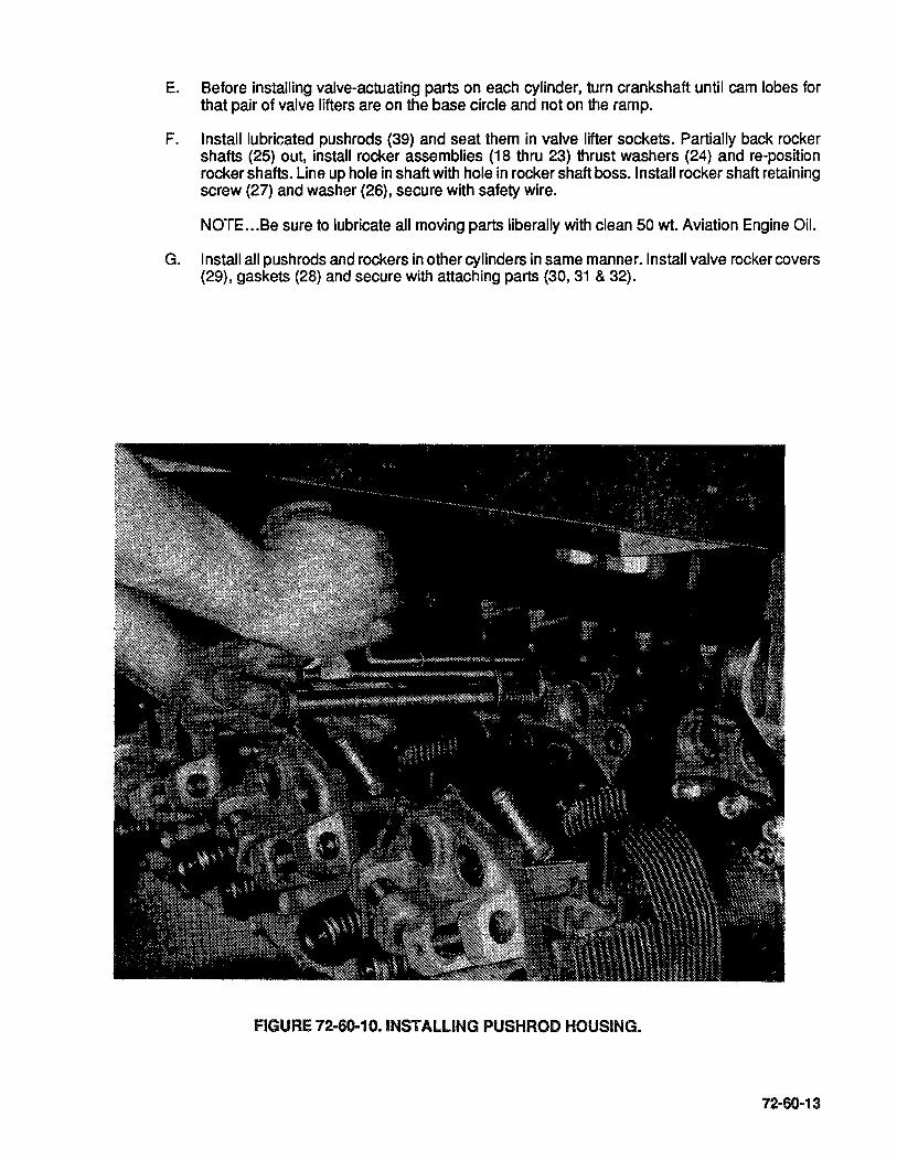
E. Before installing valve-actuating parts on each cylinder, turn crankshaft until cam lobes for that pair of valve lifters are on the base circle and not on the ramp.
F. Installlubricatedpushrods (39) and seat them in valve lifter sockets. Partially back rocker shafts (25) out, install rocker assemblies (18 thru 23) thrust washers (24) and re-position rocker shafts. Line up hole in shaft with hole in rocker shaft boss. Install rocker shaft retaining screw (27) and washer (26), secure with safety wire.
NOTE ... Be sure to lubricate all moving parts liberally with clean 50 wt. Aviation Engine Oil.
G. Install all pushrods and rockers in other cylinders in same manner. Install valve rocker covers (29), gaskets (28) and secure with attaching parts (30,31 & 32).
fiGURE 72-60-10. INSTALLING PUSHROD HOUSING.
72-60-13
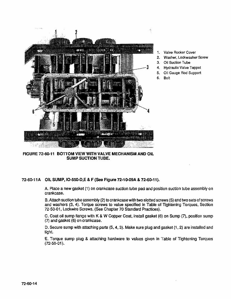
1. Valve Rocker Cover 2. Washer, Lockwasher Screw 3. Oil Suction Tube 4. Hydraulic Valve Tappet 5. Oil Gauge Rod Support 6. Bolt
FIGURE 72-60-11 BOTTOM VIEW WITH VALVE MECHANISM AND OIL SUMP SUCTION TUBE.
72-60-11A OIL SUMP, IO-550-D,E & F (See Figure 72-10-09A & 72-60-11).
72-60-14
A. Place a new gasket (1) on crankcase suction tube pad and position suction tube assembly on crankcase.
B. Attach suction tube assembly (2) to crankcase with two slotted screws (5) and two sets of screws and washers (3, 4). Torque screws to value specified in Table of Tightening Torques, Section 72-50-01, Lockwire Screws. (See Chapter 70 Standard Practices).
C. Coat oil sump flange with K & W Copper Coat, install gasket (6) on Sump (7), position sump (7) and gasket (6) on crankcase.
D. Secure sump with attaching parts (5,4, 3). Make sure plug and gasket (1,2) are installed and tight.
E. Torque sump plug & attaching hardware to values given in Table of Tightening Torques (72-50-01 ).
72-60-118 OIL SUMP 10-550-L (See Figure 72·10-098 & 72-60-11).
A. Place new gasket (1) on crankcase suction tube pad and position suction tube assembly on crankcase.
B. Attach suction tube assembly (2) to crankcase with two slotted screw (5) and two sets of screw and washers (3, 4). Torque screws to value specified in Table of Tightening Torques, Section 72-50-01, Lockwire screws. (See Chapter 70 Standard Practices).
C. Coat oil sump flange with TCM GasketSealant642188-1, install gasket (6) on sump (7), position sump (7) and gasket (6) on crankcase.
D. Secure sump with attaching parts (8, 9, 10). Install plug and gasket (11, 12).
E. Torque sump plug & attaching hardware to values given in Table of Tightening Torques 72-50-01.
72-60-12A INDUCTION SYSTEM 10-550-0 (See Figure 72-10-08A).
NOTE ... Engine should still be in inverted position.
A. Push a new hose (9) on both ends of center riser (2). Slide a hose clamp (7) on both hoses to a position midway on overlapping portion. Turn each clamp so that screwdriver can be aligned with screw yet remain clear of stand when induction riser bank is installed on engine. Tighten screw only enough to hold clamp in position.
B. Place a hose clamp (7) onto each end of end risers (2 & 3). Push end risers (2,3) into hoses previously installed on center intake riser. Work hose clamps over ends of hoses, but not past bead. Do not tighten at this time.
C. Push a hose on each front end rear intake riser and work clamp over ends of hoses but not past bead. Tighten these clamps.
D. Using procedure above, assemble 1-3-5 side induction riser bank.
E. Lay a new gasket (1) on intake flange of each cylinder. Position each assembly of risers and hoses on its proper bank of cylinders and adjust so that all flanges seat squarely on cylinder ports.
F. Attach intake flanges to cylinders with four sets of attaching hardware (4,5,6). Position clamp on two center hoses on each side, inside tube beads and tighten.
G. Push hose clamp on elbows (10,11) and push elbow into connecting hoses of rear risers. Position clamps and tighten only enough to hold tubes.
H.lnstall clamp (13) and bracket (12) on balance tube (14). Push tube ends into connecting hoses installed on front intake tubes. Position clamp (13) and secure bracket (12) to sump with attaching hardware (15,16). Position clamp assemblies (9) over tube beads and tighten.
I. Position air throttle and control unit (17) with hoses (9) and clamps (7) in its proper location. Position hoses over heads and tighten clamps.
72-60-128 INDUCTION SYSTEM 10-550-E (See Figure 72-10-088).
Note ... Engine should still be in inverted position.
A. Push a new hose (10) on both ends of center riser (2). Slide a hose clamp (8) on both hoses to a position midway on overlapping portion. Turn each clamp so that screwdriver can be aligned with screw yet remain clear of stand when induction riser bank is installed on engine. Tighten screw only enough to hold clamp in position.

B. Place hose clamps (7,8) onto each end of end risers (2 & 3). Push end risers (2 & 3) into hoses previously installed on center intake riser. Work hose clamps over ends of hoses, but not past bead. Do not tighten at this time.
C. Push a hose on each front and rear intake riser and work clamp over ends of hoses but not past bead. Tighten these clamps.
D. Using procedure above, assemble remaining induction risers.
E. Install a new gasket (1) on intake flange of each cylinder. Position each assembly of risers and hoses on its proper bank of cylinders and adjust so that all flanges seat squarely on cylinder ports.
F. Attach intake flanges to cylinders with six sets of attaching hardware (4, 5, 6). Position clamp on two hoses, center on each side inside tube beads and tighten.
G. Push hose clamp on elbows (11,12) and push elbows into connecting hoses of rear risers. Position clamps and tighten only enough to hold tubes.
H.lnstall clamp (15) and bracket (16) on balance tube (14). Push tube ends into connecting hoses installed on front intake tubes. Position clamp (15) and secure bracket (16) to sump with attaching hardware (17,18). Position clamp assemblies (9) overtube beads and tighten. Rotate engine stand so that engine is in upright position.
I. Secure support bracket (19) to idlergear support pin studs with attaching hardware (35,36) Figure 72-10-15. Torque nuts (35) to applicable torque in Table of Tightening Torques 72-50-01.
J. Install throttle assembly support brackets (25) on engine and secure using attaching hardware (29,30), attach bracket (32) to brackets (25) with attaching hardware (26,27 & 28).
K. Position air throttle and control assembly on bracket (32) and secure with attaching harware (33,34 & 35).
L. Install new bushings (24) in bracket (19), loosely assembly brackets (22, 23) on bracket (19) with attaching hardware (20,21). Secure brackets (22, 23) to throttle assembly using airframe supplied attaching hardware. Tighten all hardware to limits specified in Table of Tightening Torques 72-50-01.
72-60-12C INDUCTION SYSTEM IO-5509-F & L (See Figure 72-10-0BC).
72·60-16
NOTE ... Engine should still be in inverted position.
A. Push a new hose (10) on both ends of center riser (2). Slide a hose clamp (8) on both hoses to a position midway on overlapping portion. Turn each clamp so that screwdriver can be aligned with screw yet remain clear of stand when induction riser bank is installed on engine. Tighten screw only enough to hold clamp in position.
B. Place a hose clamp (7) onto each end of end risers (2,3). Push end risers (2,3) into hoses previously installed on center intake riser. Work hose clamps over ends of hoses, but not past bead. Do not tighten at this time.
C. Push a hose on each front and rear intake riser and work clamp over ends of hoses but not past bead. Tighten these clamps.
D. Using procedure above, assemble 1-3-5 side induction riser bank.
E. Lay a new gasket (1) on intake flange of each cylinder. Position each assembly of risers and hoses on its proper bank of cylinders and adjust so that all flanges seat squarely on cylinder ports.
F. Attach intake flanges to cylinders with four sets of attaching hardware (4,5,6). Position clamp on two center hoses on each side inside tube beads and tighten.
G. Push hose clamp on elbows (11 ,12) and push elbows into connecting hoses of rear risers. Position clamps and tighten only enough to hold tubes.
H. Install clamp (15) and bracket (14) on balance tube (16). Push tube ends into connecting hoses installed on front intake tubes. Position clamp (15) and secure bracket (14) to sump with attaching hardware (17, 18). Position clamp assemblies (9) over tube bead and tighten.
I. Secure brackets (28) to sump with corner sump bolts (33) and washers (32). Place brackets (28) one over and one under bracket (25). Secure brackets with attaching hardware (29, 30, 31). Rotate engine stand so that engine is in upright position.
J. Install throttle support bracket (22) on magneto drive adapter studs and idler gear support studs. Secure brackets with adapter and support pin hardware. Position air throttle and control assembly on bracket (25), secure with attaching hardware (26, 27). Install bushing sleeve (20, 21) in throttle assembly and secure with attaching hardware (23, 24).
K. Slide clamp (7) onto elbows (11 & 12). Install hoses (10) between elbows and throttle. Work clamps onto hose ends and tighten.
L. Torque applicable attaching hardware to values given in Table of Tightening Torques 72-50-01.
72-60-13A FUEL INJECTION 10-550-0 (See Figure 72-10-06A)
A. Apply TCM PIN 646943 Anti-Seize compound to nozzle threads. Install fuel nozzle assemblies (29) into engine cylinders. Install fuel lines (28) between nozzles and manifold valve.
CAUTION ... Do not use teflon tape on fuel injection assembly fittings.
B. Install fuel pump gasket (3) on pump mount studs.
C. Install plug (2) into drive gear (1). Liberally coat gear (1) and drive coupling (4) with clean 50 wt. Aviation Engine Oil. Install coupling and drive gear on fuel pump (5).
D. Install fuel pump (5) on crankcase studs and secure with attaching hardware (32, 33, 34).
E. Install fuel hose (27) between fuel control outlet and manifold valve inlet. Install fuel hose (26) between fuel control and fuel pump mixture return. Install fuel hose (25) on fuel pump inlet.
F. Torque nozzles, "B" nuts and applicable hardware to values given in Table of Tightening Torques 72-50-01.
G. Attach fuel lines (28) to brackets (30) with clamps (31).
72-60-138 FUEL INJECTION 10-550-E (See Figure 72-10-068)
A. Apply TCM PIN 646943 Anti-Seize compound to nozzle threads. Install fuel nozzle assemblies (30) into engine cylinders. Install fuel lines (29) between nozzles and manifold valve.
CAUTION ... Do not use teflon tape on fuel injection assembly fittings.
B. Install fuel pump gasket (3) on pump mount studs.
C. Install plug (2) into drive gear (1). Liberally coat gear (1) and drive coupling (4) with clean 50 wt. Aviation Engine Oil. Install coupling and drive gear on fuel pump (5).
72-60-17

D. Install fuel pump (5) on crankcase studs and secure with attaching hardware (33, 34, 35).
E. Install fuel hose (28) between fuel control outlet and manifold valve inlet. Install fuel hose (26) between fuel control and fuel pump mixture return. Install fuel hose (27) on fuel pump inlet.
F. Torque nozzles, "B" nuts and applicable hardware to values given in Table of Tightening Torques 72-50-01.
G. Attach fuel lines (29) to bracket (31) with clamps (32).
72-60-13C FUEL INJECTION IO-550-F & L (See Figure 72-10-06C).
A. Apply TCM PIN 646943 Anti-Seize compound to nozzle threads. Install fuel nozzle assemblies (29) into engine cylinders. Install fuel lines (28) between nozzles and manifold valve.
CAUTION ... Do not use teflon tape on fuel injection assembly fittings.
B. Install fuel pump gasket (3) on pump mount studs.
C. Install plug (2) into drive gear (3). Liberally coat gear (3) and drive coupling (4) with clean 50 wt. Aviation Engine Oil. Install coupling and drive gear on fuel pump (5).
D. Install fuel pump (5) on crankcase studs and secure with attaching hardware (32, 33, 34).
E. Install fuel hose (27) between fuel control outlet and manifold valve inlet. Install fuel hose (26) between fuel control and fuel pump mixture return. Install fuel hose (25) on fuel pump inlet.
F. Torque nozzles, "B" nuts and applicable hardware to values given in Table of Tightening Torques 72-50-01.
G. Attach fuel lines (28) to brackets (30) with clamps (31).
72-60-14 MAGNETO DRIVE GEARS (See Figures 72-10-07 & 72-60-14).
72-60-18
A. With engine in upright position, insert one pressed steel retainer (22) into each gear hub slot.
B. Insert two bushings (21) into each retainer, rounded long edges first. USing a small paint brush dab a small amount of Molyshield grease between rubber bushing ends on both sides of sleeve. This allows magneto drive lugs to Slip in position easier.
C. Turn the crankshaft to the No.1 cylinder advance firing angle as described in Section 72-60-15. Install sleeve (19) into magneto drive gear (20). Using clean 50 wt. Aviation Engine Oil, lubricate each gear (20) and insert into bushings (i5). Observe the shaft ends from the rear as they are carefully pushed through the adapter oil seals to make sure the oil seal lips are not reversed or damaged. Mesh the magneto drive gears to the idler gear at the approximate position shown in Figure 72-60-14. These positions will vary slightly due to the difference in magnetos and gears.

FIGURE 72·60·14 POSITION OF MAGNETO COUPLINGS.
72-60-15 PLACING CRANKSHAFT IN TIMING POSITION.
In conducting magneto timing, the use of a positive dead center locator, protractor and pointer are the most accurate tools to use. Tools which call for a specific arm on the piston dome are more susceptible to error.
NOTE ... lf the engine is equipped with a right angle drive starter adapter and does not freely turn in the opposite direction of normal rotation, the starter motor should be disengaged or removed from the starter adapter. Some right angle starter drive adapters incorporate an over-riding spring clutch design that restricts engine rotation in the opposite direction of normal rotation.
CAUTION ... The importance of establishing and maintaining correct magneto to engine timing cannot be overemphasized. Incorrect timing, in addition to producing a rough running engine, can lead to detonation, pre-ignition, possible internal engine damage or failure.
A. Direct Drive Engines, Timing Procedure.
1. Remove all top spark plugs. Rotate piston to the start of the compression stroke. Install the top dead center locator into No.1 cylinder top spark plug hole.
2. Install timing disc of indicator being used on crankshaft.
3. Turn crankshaft slowly in direction of rotation until piston lightly touches TDC locator.
4. Rotate disc of timing indicator until top center mark is under the pointer.
72·60-19

5. Slowly turn crankshaft in opposite direction until piston lightly touches TOC locator. Observe reading on disc under the pointer and move the disc to exactly one-half of the number of degrees observed toward the top center mark. You have now located top dead center.
6. Remove TOe locator from the cylinder and find the compression stroke on No.1 cylinder by placing a finger over the spark plug hole, or any other adequate method. As you come up on compression, stop the pointer at the TOe location as determined in step 5.
7. To either check the magneto timing or to time the magneto to the engine, move the propeller in the opposite direction of rotation past the specified magneto timing setting and then back in the direction of rotation until the desired setting before top dead center is under the pointer. (This removes the factor of gear backlash).
MODEL . . . . . . . . . . . . . . . . . . . . . . . . RIGHT MAG<D LEFT MAG<D 10-550-0, E, F & L .................. 22' BTC 22' BTC
CD Magneto setting tolerance to be plus or minus one (1) degree unless otherwise noted.
72-60-16 MAGNETO
A. Remove inspection hole plugs from magnetos.
B. Turn impulse coupling backward, so latches will not engage, until timing pointer inside inspection hole is aligned with marked distributor gear tooth.
NOTE ... See TCM Service Bulletins M82-12, M84-8 or current revisions as applicable.
e. Without turning the magneto coupling, hold the magneto in the horizontal position it will occupy when installed, and check alignment of gear coupling slot and impulse coupling lugs. If not aligned, pull gear out of mesh (but not out of oil seal) and turn to correct alignment. Push gear back into mesh.
O. Place new gasket on magneto flange and install magneto carefully so drive coupling lugs mate with slots of drive bushings. Install holding washers, lockwashers and nuts, but tighten only enough to permit turning the magneto for final timing, without looseness. Install right magneto with outer end slightly below horizontal and left magneto with outer end Slightly above horizontal.
E. Connect timing light lead to ground terminal of each magneto. Both timing lights should be on. Tap the right magneto up with a non-marring hammer until the light goes out. Tap the left magneto down until the light goes out. Secure magnetos.
F. Turn the crankshaft a few degrees counterclockwise, then clockwise until the timing indicators pointer is pointing to the correct degree for model engine. Both timing lights should go out at the same time. The timing mark on the crankshaft flange should also align with crankcase parting flange.
G. Install gaskets and covers on mount pads behind magneto drive gears and attach with four sets of plain washers, lockwashers and nuts.
72-60-17 IGNITION HARNESS (See Figures 72-10-05 A & B, 72-60-17).
72-60-20
A. The ignition harness assembly must be replaced 100% at engine overhaul. The high tension cable outlet plates can be attached to either magneto in only one position. The very shortest ignition cable is for No. 1 upper spark plug, and identifies proper assembly for the right magneto. Notice the "1" on the outlet plates next to the No. 1 cylinder cable outlet holes.
B. Attach cable outlet plate to magneto.
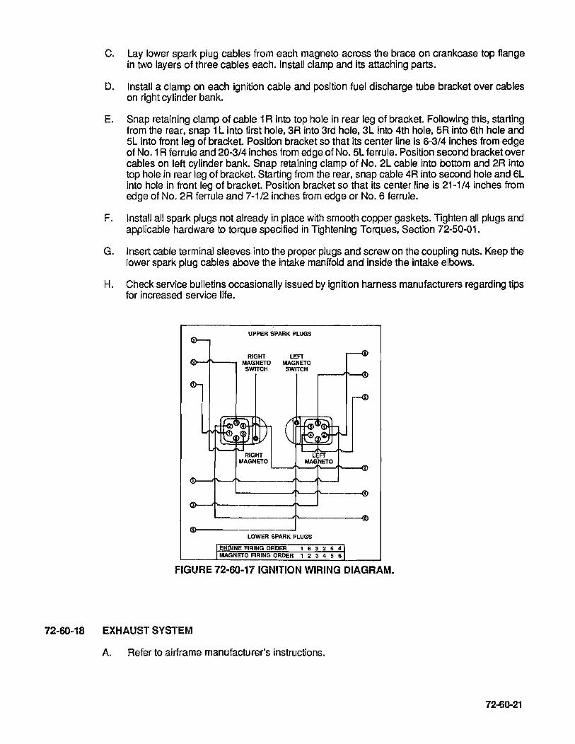
C. Lay lower spark plug cables from each magneto across the brace on crankcase top flange in two layers of three cables each. Install clamp and its attaching parts.
D. Install a clamp on each ignition cable and position fuel discharge tube bracket over cables on right cylinder bank.
E. Snap retaining clamp of cable 1 R into top hole in rear leg of bracket. Following this, starting from the rear, snap 1 L into first hole, 3R into 3rd hole, 3L into 4th hole, 5R into 6th hole and 5L into front leg of bracket. Position bracket so that its center line is 6-3/4 inches from edge of No.1 R ferrule and 20-3/4 inches from edge of No. 5L ferrule. Position second bracket over cables on left cylinder bank. Snap retaining clamp of No. 2L cable into bottom and 2R into top hole in rear leg of bracket. Starting from the rear, snap cable 4R into second hole and 6L into hole in front leg of bracket. Position bracket so that its center line is 21-1/4 inches from edge of No. 2R ferrule and 7-1/2 inches from edge or No.6 ferrule.
F. Install all spark plugs not already in place with smooth copper gaskets. Tighten all plugs and applicable hardware to torque specified in Tightening Torques, Section 72-50-01.
G. Insert cable terminal sleeves into the proper plugs and screw on the coupling nuts. Keep the lower spark plug cables above the intake manifold and inside the intake elbows.
H. Check service bulletins occasionally issued by ignition harness manufacturers regarding tips for increased service life.
UPPER SPARK PLUGS
RIGHT LEFT I!i\-.,Jf\--_ MAGNETO MAGNETO
SWITCH SWITCH
RIGHT MAGNETO
LOWER SPARK PLUGS
ENGINE FIRING ORDER 1 6 3 2 5 4 MAGNETO FIRING ORDER 1 2 3 4 5 6
FIGURE 72-60-17 IGNITION WIRING DIAGRAM.
72-60-18 EXHAUST SYSTEM
A. Refer to airframe manufacturer's instructions.
72-60-21

72-60-22
INTENTIONALL Y
LEFT
BLANK
72·70-00
72-70-01 .
72-70-02
72-70-03
72-70-04
72-70-05
72-70-06
72-70-07
72-70-08
72-70-09
72-70-10
72-70-11
72-70-12
72-70-13
72-70-14
72·70-15
SECTION 72-70 TESTING AFTER OVERHAUL
TESTING AFTER OVERHAUL
Test Stand
Test Club
Cooling Air Scoop
Induction Air Intake
Exhaust Stacks
Controls
Electrical Wiring
Instruments
Breather
Fuel System
Governor Pad Cover
Engine Test
Starting Procedure
Overhaul Test Run
Test Flight
72·70·01

72-70-02
INTENTIONALL Y
LEFT
BLANK
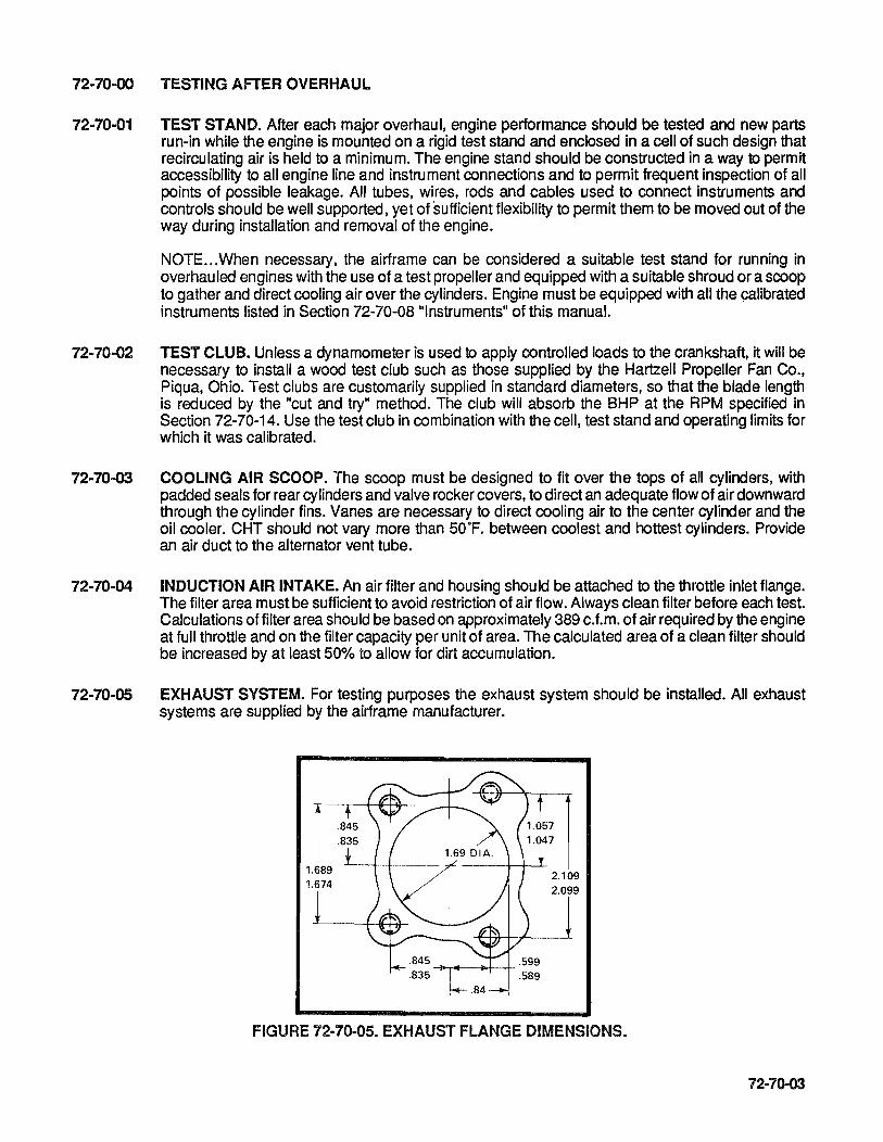
72-70-00 TESTING AFTER OVERHAUL
72·70-01 TEST STAND. After each major overhaul, engine performance should be tested and new parts run-in while the engine is mounted on a rigid test stand and enclosed in a cell of such design that recirculating air is held to a minimum. The engine stand should be constructed in a way to permit accessibility to all engine line and instrument connections and to permit frequent inspection of all points of possible leakage. All tubes, wires, rods and cables used to connect instruments and controls should be well supported, yet of sufficient flexibility to permit them to be moved out of the way during installation and removal of the engine.
NOTE ... When necessary, the airframe can be considered a suitable test stand for running in overhau led engines with the use of a test propeller and equipped with a suitable shroud or a scoop to gather and direct cooling air over the cylinders. Engine must be equipped with all the calibrated instruments listed in Section 72-70-08 "Instruments" of this manual.
72-70-02 TEST CLUB. Unless a dynamometer is used to apply controlled loads to the crankshaft, it will be necessary to install a wood test club such as those supplied by the Hartzell Propeller Fan Co., Piqua, Ohio. Test clubs are customarily supplied in standard diameters, so that the blade length is reduced by the "cut and try" method. The club will absorb the BHP at the RPM specified in Section 72-70-14. Use the test club in combination with the cell, test stand and operating limits for which it was calibrated.
72-70-03 COOLING AIR SCOOP. The scoop must be designed to fit over the tops of all cylinders, with padded seals for rear cylinders and valve rocker covers, to direct an adequate flow of air downward through the cylinder fins. Vanes are necessary to direct cooling air to the center cylinder and the oil cooler. CHT should not vary more than 50·F. between coolest and hottest cylinders. Provide an air duct to the alternator vent tube.
72-70-04 INDUCTION AIR INTAKE. An air filter and housing should be attached to the throttle inlet flange. The filter area must be sufficient to avoid restriction of air flow. Always clean filter before each test. Calculations of filter area should be based on approximately 389 c.f.m. of air required by the engine at full throttle and on the filter capacity per unit of area. The calculated area of a clean filter should be increased by at least 50% to allow for dirt accumulation.
72-70-05 EXHAUST SYSTEM. For testing purposes the exhaust system should be installed. All exhaust systems are supplied by the airframe manufacturer.
FIGURE 72·70-05. EXHAUST FLANGE DIMENSIONS.
72-70-03

72-70-06 CONTROLS. The only controls required are a mixture control and throttle control capable of operating the fuel control and metering shafts through their complete ranges, and a standard twin magneto switch connected to the magneto ground terminals.
72-70-07 ELECTRICAL WIRING. A storage battery must be connected by a No. 0 stranded copper cable from its positive terminal to the power terminal of the starter or starter solenoid. The battery negative terminal must be connected to the engine or both negative battery terminal and engine may be grounded. A small insulated wire should connect the starter solenoid coil terminal to a 5 ampere pushbutton switch. The other switch terminal must be connected to the engine or both to common ground.
72-70-08 INSTRUMENTS. The control panel should be equipped with the following calibrated engine instruments.
A. A mechanically driven (counterclockwise, 1/2 engine RPM) tachometer and flexible shaft assembly is required.
B. An oil pressure gage and tube connection.
C. An oil temperature gage and capillary assembly.
O. A cylinder head temperature gage and wiring to each cylinder. (See Test Operating Limitations for different maximum temperatures).
E. A water manometer with rubber hose connection to the vacuu m pump oil return hole at the rear of the crankcase.
F. An ammeter connected in the generator or alternator circuit.
G. Fuel flow gage or fuel pressure gage.
H. Manifold pressure gage.
72-70-09 BREATHER. A substantial hose of 3/4 inch 10 should be securely clamped over crankcase breather elbow and supported so as to lead to a point above and to the rear of the engine.
72-70-10 FUEL SYSTEM. The test stand fuel system is to incorporate an auxiliary pump capable of delivering fuel to and through the engine system at a pressure of 2 to 2 112 p.s.i. indication on fuel pressure gage. Means of determining, by weight fuel consumption for given periods of time and at specified percentage of power, should also be included. Connect stand fuel supply line to upper elbow projecting from left side offuel pump shroud. Connectfuel pump-to-supply tank return line to upper elbow projecting from right side of fuel pump. Connect fuel pressure gage line to the fitting projecting from the center rear of fuel manifold valve.
72-70-11 GOVERNOR PAD COVER. A removable oil transfer tube conducts oil under pressure from the front main bearing through the crankshaft to the propeller hub. Crankshafts are equipped with an oil transfer collar to supply the governor controlled oil to the crankshaft for use with an oil controlled propeller. When a test club or fixed pitch propeller is used for testing purposes, the governor pad cover must have an internal grooved surface to allow the Circulating oil to lubricate the oil transfer collar. The governor pad cover is not needed if a propeller governor is installed.
72-70-04

72-70-12 ENGINE TEST
A. Make one check on performance of each magneto alone at 21 00 RPM. Clear spark plugs by operating with both magnetos on for a few seconds between checks.
B. Take instrument readings at the beginning, in the middle, and at the end of the full throttle period. Take one reading during each of the other periods as soon as conditions have stablized.
NOTE ... The maximum allowable cylinder head temperature and the maximum allowable oil temperature must not be exceeded at any time during the test.
C. Extend the second period of each test schedule, if necessary, to raise the oil temperature to 100°F.
D. Run the engine according to the schedule in this section after a major overhaul. (Standard Acceptance Test).
NOTE ... lf tests must be conducted in extremely cold weather, it may be necessary to shield the crankcase from the cooling air stream, since it takes some heat from the oil.
72-70-13 STARTING PROCEDURE
A. Fuel Selector - on appropriate tank.
B. Throttle open approximately 1" inch.
C. Propeller control high RPM.
D. Mixture control - full rich.
E. Battery switch on.
F. Boost pump or primer (Prime in accordance with airframe manufacturer's recommendation).
G. Magneto/Start Switch - start position, as engine starts release the Magneto/Start switch to the "both" position.
WARNING ... Starting an engine with a flooded intake system will result in hydrostatic lock and subsequent engine malfunction.
CAUTION ... Do not engage the starter when the engine is running, as this will damage the starter. Do not crank for longer than thirty seconds at a time, as this may cause the starter motor to overheat. If the engine does not start after thirty seconds of cranking, allow a 3 to 5 minute cooling period before attempting to restart.
CAUTION ... ff engine kicks back when starting, DO NOT attempt to start. The ignition starting system is inoperative and must be repaired before damaging starter adapter assembly.
H. Oil Pressure - 10 PSI minimum within 30 seconds.
72-70-05

72-70-14A OVERHAUL TEST RUN
STANDARD ACCEPTANCE TEST
Period Time-Minutes RPM
1 2 1200
2 2 1600
3 2 2000
4 4 2450
5 15 CD Rated RPM
6 5 @@CD Engine Parameter
Checks
7 5 @ Idle RPM 600 ± 25
8 15 75% Power 2450
9 15 @@ 75% Power 2450
90 TOTAL MINUTES
NOTE ... Engine oil pressure must be supplied to propeller transfer collar during all testing.
<D Adjust Engine - Fuel Flow and Pressure (Reduce RPM For Adjustments)
@ Check Fuel Injection, Oil Pressure, Oil Temperature, M.A.P., C.H.T. and Alternator.
® Magneto Drop and Spread To Be Taken. Engine Must Be Throttled To Specified RPM and Temperature Allowed To Settle Out Before Taking Magneto Drop And Spread. Mag Check 21 00 RPM.
@ Cooling Period - 300· Max. C.H.T. Before Shut-Down, Recheck Idle Adjustments.
@ Runs 8 And 9 Must Be Made With Stops For Leak Checks At The End Of Each Run. The Engine Will Not Be Accepted Until Two Successive 15 Minute Runs Are Made With No Leaks.
@ Fuel And Oil Leaks Are Not Acceptable.
CD See Test Operating Limits Section 77-10-00.
72-70-06
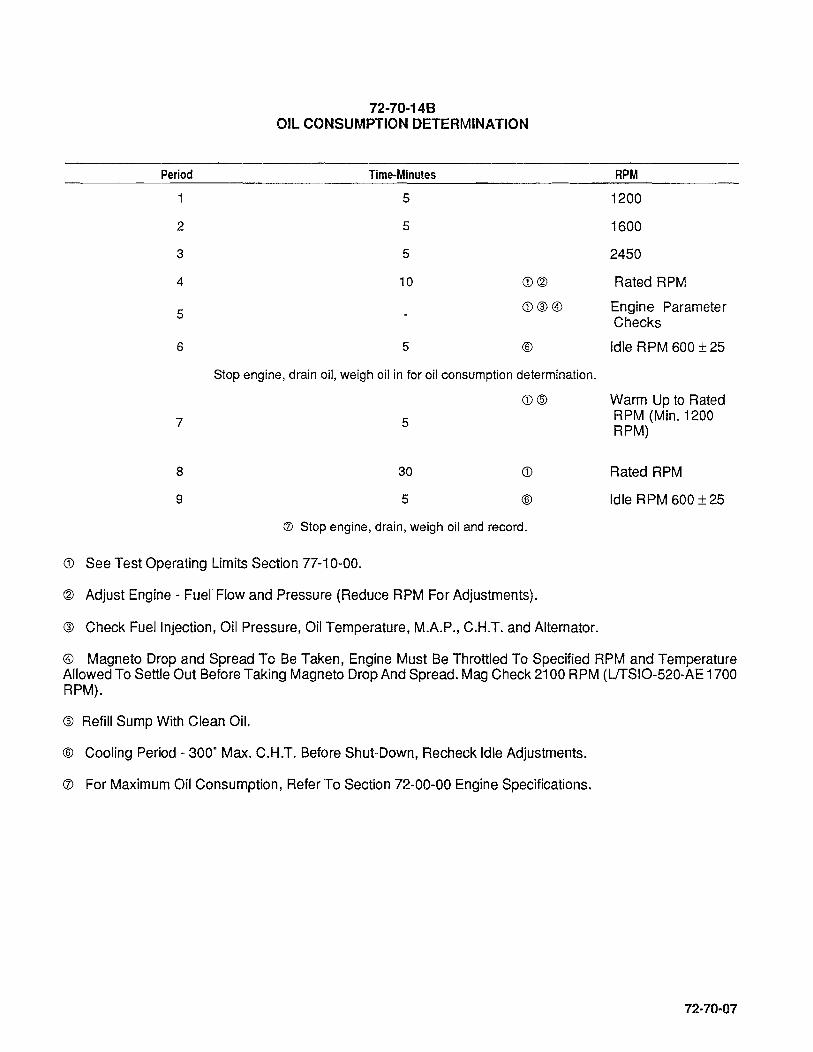
Period
2
3
4
5
6
7
8
9
72·70·148 OIL CONSUMPTION DETERMINATION
Time-Minutes
5
5
5
10
5
<D@
<D@@)
®
Stop engine, drain oil, weigh oil in for oil consumption determination.
<D®
5
30
5
<D
®
(J) Stop engine, drain, weigh oil and record.
<D See Test Operating Limits Section 77-10-00.
@ Adjust Engine - Fuel Flow and Pressure (Reduce RPM For Adjustments).
@ Check Fuel Injection, Oil Pressure, Oil Temperature, M.A.P., C.H.T. and Alternator.
RPM
1200
1600
2450
Rated RPM
Engine Parameter Checks
Idle RPM 600 ± 25
Warm Up to Rated RPM (Min. 1200 RPM)
Rated RPM
Idle RPM 600 ± 25
@) Magneto Drop and Spread To Be Taken, Engine Must Be Throttled To Specified RPM and Temperature Allowed To Settle Out Before Taking Magneto Drop And Spread. Mag Check 2100 RPM (LfrSIO-520-AE 1700 RPM).
® Refill Sump With Clean Oil.
@ Cooling Period - 300· Max. C.H.T. Before Shut-Down, Recheck Idle Adjustments.
(J) For Maximum Oil Consumption, Refer To Section 72-00-00 Engine Specifications.
72-70-07

FEATURE
MAXIMUM TAKEOFF POWER
12-10-14C OVERHAUL TEST RUN TEST OPERATING LIMITS
10-550-0, E, F & L ....................... 300 @ 2700
IDLING SPEED 10-550-0, E, F & L ......................... 600 ± 25
FUEL GRADE 10-550-0, E, F & L ......................... 100-100LL
FUEL PUMP PRESSURE AT FULL THROTTLE (PSI)
10-550-0, E, F & L ......................... 33.0-36.0
FUEL PUMP PRESSURE AT IDLE (PSI) 10-550-0, E, F & L ............ 8.0-10.0
METERED FUEL PRESSURE AT FULL THROTTLE (PSI)
All Models ................... See Metered Fuel Pressure Performance curve.
ENGINE INTAKE AIR TEMPERATURE (ALL MODELS) ............. AMBIENT
MANIFOLD VACUUM AT FULL THROTTLE (IN. HG.) 10-550-0, E, F & L .. 3.0" HG MAX.
MANIFOLD PRESSURE AT IDLE (IN. HG.) (ALL MODELS) ........ 18.5" H.G. MAX.
OIL GRADE
NORMAL SERVICE ABOVE 30·F. . ................ SAE 50
BELOW 50°F ....•..................... .. SAE 30 OR
10W30
MAX. OIL CONSUMPTION (LB.lBHP/HR. MAX. AT RATED POWER AT RPM)
ALL MODELS
.006 LBS. X % POWER 100
OIL TEMPERATURE (DESIREO RANGE) ..................... 150°-200°F OIL TEMPERATURE (MAX.) ............................... 240°F OIL PRESSURE AT FULL THROTTLE (PSI MAX.)
(OIL TEMPERATURE 175°F.-185°F.) ........................ .40-60 OIL PRESSURE AT IDLE (PSI MIN.)
(OIL TEMPERATURE 130°F.-140°F.) ..................... 30 PSI MIN. IGNITION TIMING IO-550-0,E,F & L
LEFT MAGNETO °BTC ........................ 22°BTC ± 1° RIGHT MAGNETO °BTC ....................... 22'BTC ± 1 °
CYLINDER HEAD TEMPERATURE (MAX.) WITH BAYONET THERMOCOUPLE .. . . . . . . . . . . . . . . . . . . . . . . . 460°F MAX.
CRANKCASE PRESSURE (MAX) (IN. H20) ........•..... .4.0" WATER MAX.
12-70-08

72-70-15 TEST FLIGHT
Ambient air and engine operating temperatures are of major concern during the test flight. Do a normal pre-flight run-up in accordance with the aircraft flight manual. Conduct a normal take-off with full power and monitor the fuel flow, RPM, oil pressure, cylinder head temperature and oil temperatures. Reduce to climb power in accordance with the flight manual and maintain a shallow climb attitude to gain optimum airspeed and cooling. On the 10-550-D, rich mixture should be used for all operations except lean for field elevation where applicable and lean to maintain smoothness during climb. On the IO-550-E, F & L, rich mixture should be used for all operations except leaning for cruise economy. All leaning operations should be performed in accordance with the airframe manufacturer's instructions.
Level flight cruise should be at 75% power with best power or richer mixture for the first hour of operation. The second hour power settings should alternate between 65% and 75% power with the appropriate best power mixture settings. Engine controls or aircraft attitude shou Id be adjusted as required to maintain engine instrumentation within specifications.
The descent should be made at low cruise power settings with careful monitoring of engine pressures and temperatures. Avoid long descents with cruise RPM and manifold pressure below 18" Hg.; if necessary decrease the RPM sufficiently to maintain manifold pressure.
Any abnormal conditions detected during test flight should be corrected and any final adjustments required should be accomplished prior to releasing the aircraft for normal service.
72-70-09

72-70-10
INTENTIONALL Y
LEFT
BLANK
SECTION 72-80 ENGINE PRESERVATION
72-80-00 ENGINE PRESERVATION
72-80-01 General
72-80-02 Flyable Storage
72-80-03 Temporary Storage
72-80-04 . Indefinite Storage
72-80-01

72-80-02
INTENTIONALLY
LEFT
BLANK

72-80-01 GENERAL
Engines in aircraft that are flown only occasionally tend to exhibit cylinder wall corrosion more than engines in aircraft that are flown frequently.
Of particular concern are new engines or engines with new or freshly honed cylinders after a top or major overhaul. In areas of high humidity, there have been instances where corrosion has been found in such cylinders after an inactive period of only a few days. When cylinders have been operated for approximately 50 hours, the varnish deposited on the cylinder wall offers some protection against corrosion. Hence a two step program for flyable storage category is recommended.
Obviously, even then proper steps must be taken on engines used infrequently to lessen the possibility of corrosion. This is especially true if the aircraft is based near the sea coast or in areas of high humidity and flown less than once a week.
In all geographical areas the best method of preventing corrosion of the cylinders and other internal parts of the engine, is to fly the aircraft at least once a week, long enough to reach normal operating temperatures, which will vaporize moisture and other by-products of combustion. In consideration of the circumstances mentioned, TCM has listed three reasonable minimum preservation procedures, that if implemented, will minimize the detriments of rust and corrosion. It is the owners responsibility to choose a program that is viable to the particular aircraft's mission.
Aircraft engine storage recommendations are broken down into the following categories:
A. Flyable Storage (Program I or II) B. Temporary Storage (up to 90 days) C. Indefinite Storage
72-80-02 FLYABLE STORAGE (Program I or II)
Program 1-
Program 11-
Engines or cylinders with less than 50 operating hours:
a. Propeller pull thru every 5 days as per paragraph A2; and b. Fly every 15 days as per paragraph A3.
Engines or cylinders with more than 50 operating hours to TBO if not flown weekly:
a. Propeller pull thru every 7 days as per paragraph A2; and b. Fly every 30 days as per paragraph A3.
1. Service aircraft per normal airframe manufacturer's instructions.
2. The propeller should be rotated by hand without running the engine. For 4 and 6 cylinder straight drive engines, rotate the engine six revolutions. Stop the propeller 45' to 90' from the original position. For 6 cylinder geared engines, rotate the propeller 4 revolutions and stop the propeller 30' to 60· from the original poSition.
WARNING ... FOR MAXIMUM SAFETY, ACCOMPLISH ENGINE ROTATION AS FOLLOWS:
a. Verify magneto switches are "OFF"
b. Throttle position "CLOSED"
c. Mixture control "IDLE CUT-OFF"
d. Set brakes and block aircraft wheels
e. Leave aircraft tie-downs installed and verify that the cabin door latch is open.
72-80..Q3

f. Do not stand within the arc of the propeller blades while turning the propeller.
3. The aircraft should be flown for thirty (30) minutes, reaching but not exceeding, normal oil and cylinder temperatures. If the aircraft cannot be flown it should be represerved in accordance with "B" (Temporary Storage) or "c" (Indefinite Storage). Ground running is not an acceptable substitute for flying.
NOTE ... If "b" in each program cannot be accomplished on schedule due to weather, maintenance, etc., pull the propeller thru daily as soon as possible.
It is necessary thatfor future reference, if required, the propeller pull thru and flight time be recorded and verified in the engine maintenance record/log with the date, time and signature.
72-80-03 TEMPORARY STORAGE (Up to 90 Days).
72-80-04
1. Preparation for Storage
a. Remove the top spark plug and spray preservative oil (lubrication Oil - Contact and Volatile Corrosion - Inhibited, MIL-L-46002, Grade 1) at room temperature, through upper spark plug hole of each cylinder with the piston in approximately the bottom dead center position. Rotate crankshaft as each pair of opposite cylinders is sprayed. Stop crankshaft with no piston at top dead center. A pressure pot or pump-up type garden pressure sprayer may be used. The spray head should have ports around the circumference to allow complete coverage of the cylinder walls.
NOTE ... Shown below is an approved preservative oil recommended for use in Teledyne Continental engines for temporary and indefinite storage:
MIL-P46002, Grade 1 Oils:
NOX RUSTVCI-105 Daubert Chemical Company
May be purchased through: Rock Island Lubricant & Chemical Company
P. O. Box 5015 1320 1 st Street
Rock Island, Illinois 61204 1-800-522-1150
b. Re-spray each cylinder without rotating crankshaft. To thoroughly cover all surfaces of the cylinder interior, move the nozzle or spray gun from the top to the bottom of the cylinder.
c. Re-install spark plugs.
d. Apply preservative to engine interior by spraying the above specified oil (approximately two ounces) through the oil filler tube.
e. Seal all engine openings exposed to the atmosphere using suitable plugs, or moisture resistant tape, and attach red streamers at each point.
f. Engines, with propellers installed, that are preserved for storage in accordance with this section should have a tag affixed to the propeller in a conspicuous place with the following notation on the tag: "DO NOT TURN PROPELLER - ENGINE PRESERVED." PRESERVATION DATE _________ ,
NOTE .. Jf engine is not returned to flyable status at the expiration of the temporary (90 day) storage, it must be preserved in accordance with the indefinite storage procedures.

2. Preparation for Service
a. Remove seals, tape, paper and streamers from all openings.
b. With bottom spark plugs removed from the cylinders, hand turn propeller several revolutions to clear excess preservative oil, then re-install spark plugs.
c. Conduct normal start-up procedure.
d. Give the aircraft a thorough cleaning and visual inspection. A test flight is recommended.
72-80-04 INDEFINITE STORAGE.
1. Preparation for Storage
a. Drain the engine oil and refill with MIL-C-6529 Type II, (Aeroshell fluid 2F). The aircraft should be flown for thirty (30) minutes, reaching, but bot exceeding normal oil and cylinder temperatures. Allow engine to cool to ambient temperature. Accomplish steps "1 .a." and" 1.b" of Temporary Storage.
NOTE ... MIL-C-6529 Type II may be formulated by thoroughly mixing one part compound MIL-C6529 Type I (Esso Rust-Ban 628, Cosmoline No. 1223 or equivalent) with three parts new lubricating oil of the grade recommended for service (all at room temperature). Single grade oil is recommended.
b. Apply preservative to engine interior by spraying MIL-P-46002, Grade 1 oil (approximately two ounces) through the oil filler tube.
2. Install dehydrator plugs MS27215-1 or -2, in each of the top spark plug holes, making sure that each plug is blue in color when installed. Protect and support the spark plug leads with AN-4060 protectors.
3. The TCM fuel injection system does not require any special preservation preparation. For preservation of the Bendix RSA-7DA1 fuel injection system, refer to the Bendix Operation and Service Manual.
4. Place a bag of desiccant in the exhaust pipes and seal the openings with moisture-resistant tape.
5. Seal the cold air inlet to the heater muff with moisture-resistant tape to exclude moisture and foreign objects.
72-80-05
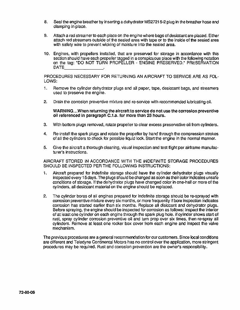
72-80-06
8. Seal the engine breather by inserting a dehydrator MS27215-2 plug in the breather hose and clamping in place.
9. Attach a red streamer to each place on the engine where bags of desiccant are placed. Either attach red streamers outside of the sealed area with tape or to the inside of the sealed area with safety wire to prevent wicking of moisture into the sealed area.
10. Engines, with propellers installed, that are preserved for storage in accordance with this section should have each propeller tagged in a conspicuous place with the following notation on the tag: "DO NOT TURN PROPELLER - ENGINE PRESERVED." PRESERVATION DATE ____________ _
PROCEDURES NECESSARY FOR RETURNING AN AIRCRAFT TO SERVICE ARE AS FOLLOWS:
1. Remove the cylinder dehydrator plugs and all paper, tape, desiccant bags, and streamers used to preserve the engine.
2. Drain the corrosion preventive mixture and re-service with recommended lubricating oil.
WARNING .•. When returning the aircraft to service do not use the corrosion preventive 011 referenced in paragraph C.1.a. for more than 25 hours.
3. With bottom plugs removed, rotate propeller to clear excess preservative oil from cylinders.
4. Re-install the spark plugs and rotate the propeller by hand through the compression strokes of all the cylinders to check for possible liquid lock. Start the engine in the normal manner.
5. Give the aircraft a thorough cleaning, visual inspection and test flight per airframe manufacturer's instructions.
AIRCRAFT STORED IN ACCORDANCE WITH THE INDEFINITE STORAGE PROCEDURES SHOULD BE INSPECTED PER THE FOLLOWING INSTRUCTIONS:
1. Aircraft prepared for indefinite storage should have the cylinder dehydrator plugs visually inspected every 15 days. The plugs should be changed as soon as their color indicates unsafe conditions of storage. If the dehydrator plugs have changed color in one-half or more of the cylinders, all desiccant material on the engine should be replaced.
2. The cylinder bores of all engines prepared for indefinite storage should be re-sprayed with corrosion preventive mixture every six months, or more frequently if bore inspection indicates corrosion has started earlier than six months. Replace all disiccant and dehydrator plugs. Before spraying, the engine should be inspected for corrosion as follows: Inspect the interior of at least one cylinder on each engine through the spark plug hole. If cylinder shows start of rust, spray cylinder corrosion preventive oil and turn prop over six times, then re-spray all cylinders. Remove at least one rocker box cover from each engine and inspect the valve mechanism.
The previous procedures are a general recommendation for our customers. Since local conditions are different and Teledyne Continental Motors has no control over the application, more stringent procedures may be required. Rust and corrosion prevention are the owner's responsibility.

CHAPTER 73 ENGINE FUEL SYSTEM
73-00-00 ENGINE FUEL SYSTEM
73-10-00 SET-UP PROCEDURE 73-10-01 Naturally Aspirated Engines
73-10-02 Fuel System Pressure and Flow Valve
73-10-03 Fuel System Troubleshooting Chart
73-00-01

73-00-02
INTENTIONAL Y
LEFT
BLANK

73-00-00 ENGINE FUEL SYSTEM
WARNING ... The use of a lower octane fuel than specified can result In destruction of an engine the first time high power Is applied. This would most likely occur on takeoff. If the aircraft Is Inadvertently serviced with the wrong grade of fuel, then the fuel must be completely drained and the tank properly serviced.
Fuel (MIN. Grade) ......................... Aviation Grade 100 or 100LL The TCM fuel injection system is of a multi-nozzle continuous flow type. Fuel flow to the cylinders is controlled by air throttle poSition, engine speed, mixture lever position and the altitude compensation feature in the fuel pump. A manual mixture control and a pressure gauge indicating metered fuel flow are provided for precise leaning at any combination of altitude and power setting.
The continuous flow system permits the use of a typical rotary vane pump with integral relief valve in place of a much more complex and more expensive plunger type pump. The relief valve maintains maximum fuel flow under full power conditions. With this system there is no need for an intricate mechanism for timing injection to the engine.
The fuel injector pump is equipped with a vapor separator where the vapor is separated from the liquid fuel by swirling action and returned to the fuel tank. The fuel injector pump forces liquid fuel into the fuel metering assembly. Fuel flow is controlled by an Altitude Compensation Feature on the E, F and L models.
The air throttle assembly includes a butterfly valve which controls the amount of air entering the intake manifold. This valve is controlled by a lever which is connected to the aircraft throttle control.
The fuel control assembly contains a metering valve and a mixtu re control valve. The metering valve is linked to the air throttle valve lever. The mixture control valve is linked to the cockpit mixture control. The fuel control by-passes excess fuel back to the fuel injector pump inlet port.
The fuel manifold valve contains a diaphram chamber and outlet ports which connect to the fuel injector lines. The spring-loaded diaphragm works with a ported plunger which distributes the precise amount of fuel, through fuel injector lines, to the fuel injector nozzles in the cylinders. Ambient air is used to vent the nozzles.
METERED FUEL PRESSURE
NOZZLE ASSEMBL
SECONDARY FUEL STRAINER
IDLE ADJUSTMENT
THROTILE LINKAGE FUEL TO AIR
IDLE SPEED ADJUSTMENT
THROTILE ASSEMBLY
THROTILE CONTROL LEVER
FIGURE 73-00-00 FUEL SYSTEM SCHEMATIC.
FUEL INLET FROM TANK
UNMETERED FUEL PRESSUR, (TEMPORARILY INSTALLED FOR
FUEL SYSTEM seT U·PI
73--00-03
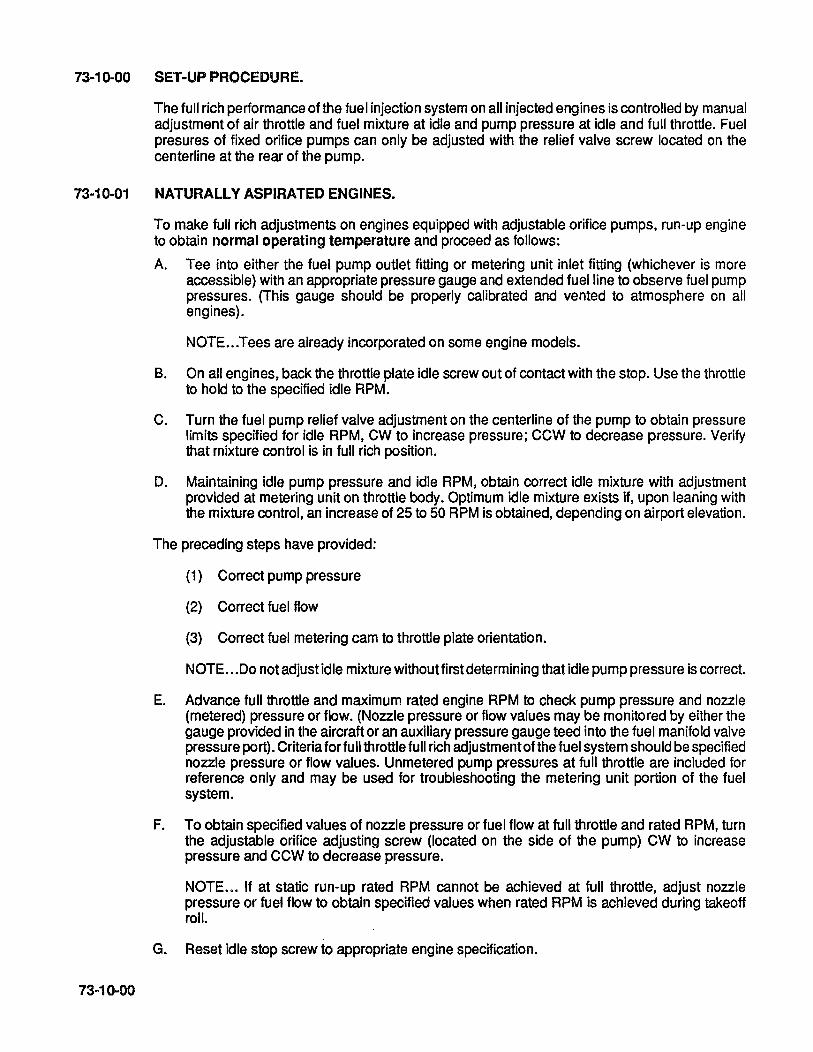
73-10-00 SET-UP PROCEDURE.
The full rich performance of the fuel injection system on all injected engines is controlled by manual adjustment of air throttle and fuel mixture at idle and pump pressure at idle and full throttle. Fuel presures of fixed orifice pumps can only be adjusted with the relief valve screw located on the centerline at the rear of the pump.
73-10-01 NATURALLY ASPIRATED ENGINES.
73-10-00
To make full rich adjustments on engines equipped with adjustable orifice pumps, run-up engine to obtain normal operating temperature and proceed as follows:
A. Tee into either the fuel pump outlet fitting or metering unit inlet fitting (whichever is more accessible) with an appropriate pressure gauge and extended fuel line to observe fuel pump pressures. (This gauge should be properly calibrated and vented to atmosphere on all engines).
NOTE ... Tees are already incorporated on some engine models.
B. On all engines, back the throttle plate idle screw out of contact with the stop. Use the throttle to hold to the specified idle RPM.
C. Turn the fuel pump relief valve adjustment on the centerline of the pump to obtain pressure limits specified for idle RPM, CW to increase pressure; CCW to decrease pressure. Verify that mixture control is in full rich position.
D. Maintaining idle pump pressure and idle RPM, obtain correct idle mixture with adjustment provided at metering unit on throttle body. Optimum idle mixture exists if, upon leaning with the mixture control, an increase of 25 to 50 RPM is obtained, depending on airport elevation.
The preceding steps have provided:
(1) Correct pump pressure
(2) Correct fuel flow
(3) Correct fuel metering cam to throttle plate orientation.
NOTE •.. 00 not adjust idle mixture without first determining that idle pump pressure is correct.
E. Advance full throttle and maximum rated engine RPM to check pump pressure and nozzle (metered) pressure or flow. (Nozzle pressure or flow values may be monitored by either the gauge provided in the aircraft or an auxiliary pressure gauge teed into the fuel manifold valve pressure port). Criteria for fu II throttle full rich adjustment of the fuel system should be specified nozzle pressure or flow values. Unmetered pump pressures at full throttle are included for reference only and may be used for troubleshooting the metering unit portion of the fuel system.
F. To obtain specified values of nozzle pressure or fuel flow at full throttle and rated RPM, turn the adjustable orifice adjusting screw (located on the side of the pump) CW to increase pressure and CCW to decrease pressure.
NOTE ... If at static run-up rated RPM cannot be achieved at full throttle, adjust nozzle pressure or fuel flow to obtain specified values when rated RPM is achieved during takeoff roll.
G. Reset idle stop screw to appropriate engine speCification.
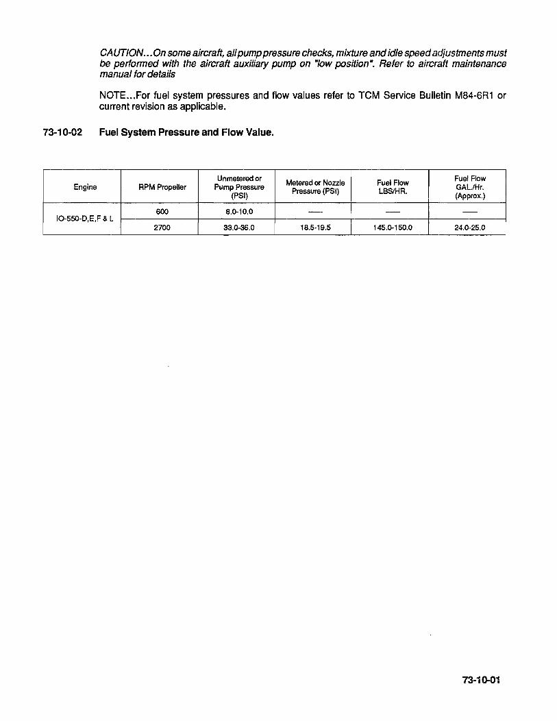
73-10-02
Engine
CAUTION ... On some aircraft, all pump pressure checks, mixture and idle speed adju.stments must be performed with the aircraft auxiliary pump on "Iow position". Refer to aircraft maintenance manual for details
NOTE ... For fuel system pressures and flow values refer to TCM Service Bulletin M84-6R1 or current revision as applicable.
Fuel System Pressure and Flow Value.
Unmetered or Metered or Nozzle Fuel Flow Fuel Flow RPM Propeller Pump Pressure Pressure (PSI) LBSlHR. GAL/Hr.
(PSI) (Approx.)
600 8.0-10.0 - - -10-550-D,E,F & L
2700 33.0-36.0 18.5-19.5 145.0-150.0 24.0-25.0
73·10-01
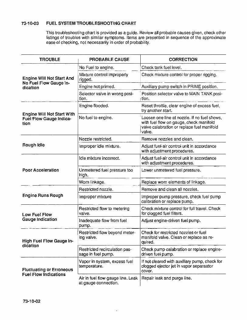
73-10-03 FUEL SYSTEM TROUBLESHOOTING CHART
This troubleshooting chart is provided as a guide. Review all probable causes given, check other listings of troubles with similar symptoms. Items are presented in sequence of the approximate ease of checking, not necessarily in order of probability.
TROUBLE PROBABLE CAUSE CORRECTION
No Fuel to engine. Check tank fuel level.
Engine Will Not Start And Mixture control improperly Check mixture control for proper rigging. rigged.
No Fuel Flow Gauge In-Engine not primed. Auxiliary pump switch in PRIME pOSition. dication
Selector valve in wrong posi- Position selector valve to MAIN TANK posi-tion. tion.
Engine flooded. Reset throttle, clear engine of excess fuel,
Engine Will Not Start With try another start.
No fuel to engine. Loosen one line at nozzle. If no fuel shows, Fuel Flow Gauge Indica-tion with fuel flow on gauge, check manifold
valve calabration or replace fuel manifold valve.
Nozzle restricted. Remove nozzles and clean.
Rough Idle Improper idle mixture. Adjust fuel-air control unit in accordance with adjustment procedures.
Idle mixture incorrect. Adjust fuel-air control unit in accordance with adjustment procedures.
Poor Acceleration Unmetered fuel pressure too Lower unmetered fuel pressure. high.
Worn linkage. Replace worn elements of linkage.
Restricted nozzle. Remove and clean all nozzles.
Engine Runs Rough Improper mixture Improper pump pressure, check fuel pump calibration or replace pump.
Restricted flow to metering Check mixture control for full travel. Check
Low Fuel Flow valve. for clogged fuel filters.
Gauge Indication Inadequate flow from fuel Adjust engine-driven fuel pump. pump.
Restricted flow beyond meter- Check for restricted nozzles or fuel
High Fuel Flow Gauge In-ing valve. manifold valve. Clean or replace as re-
quired. dication
Restricted recirculation pas- Check pump calabration or replace engine-sage in fuel pump. driven fuel pump.
Vapor in system, excess fuel If not cleared with auxiliary pump, check for
Fluctuating or Erroneous temperature. clogged ejector jet in vapor separaator
cover. Fuel Flow Indications
Air in fuel flow gauge line. Leak Repair leak and purge line. at gauge connection.
73-10-02
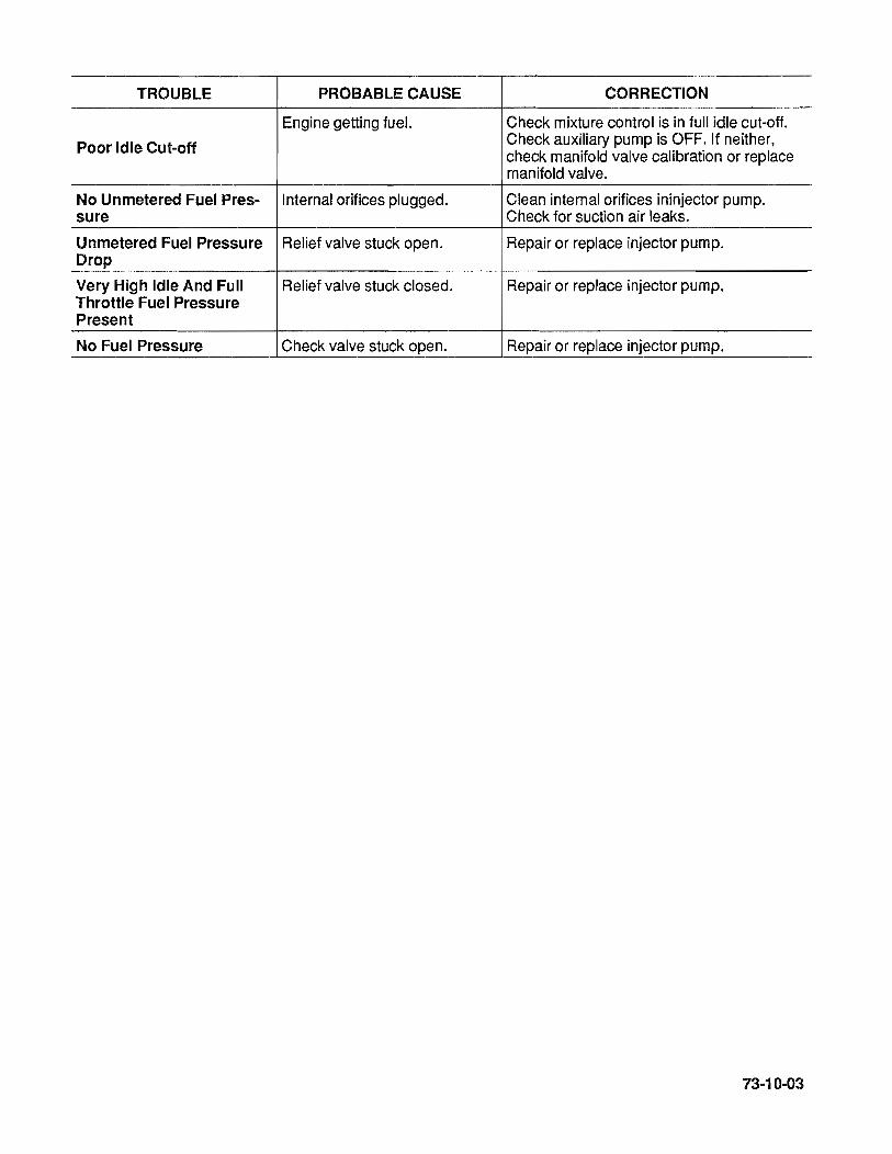
TROUBLE PROBABLE CAUSE CORRECTION
Engine getting fuel. Check mixture control is in full idle cut-oft.
Poor Idle Cut-off Check auxiliary pump is OFF. If neither, check manifold valve calibration or replace manifold valve.
No Unmetered Fuel Pres- Internal orifices plugged. Clean internal orifices ininjector pump. sure Check for suction air leaks.
Unmetered Fuel Pressure Relief valve stuck open. Repair or replace injector pump. Drop
Very High Idle And Full Relief valve stuck closed. Repair or replace injector pump. Throttle Fuel Pressure Present
No Fuel Pressure Check valve stuck open. Repair or replace injector pump.
73·10-03

73-10-04
INTENTIONALL Y
LEFT
BLANK

74-00-00
74-10-01
74-10-02
74-20-00
74-30-00
74-40-01
74-40-02
74-50-00
CHAPTER 74 IGNITION
(TCM IGNITION SYSTEM)
GENERAL
MAGNETO INSTALLATION
HARNESS ASSEMBLY INSTALLATION
IGNITION TROUBLESHOOTING
(SLICK IGNITION SYSTEM)
GENERAL
MAGNETO INSTALLATION
HARNESS ASSEMBL Y INSTALLATION
IGNITION TROUBLESHOOTING
74-00-01

74-00-02
INTENTIONALL Y
LEFT
BLANK

74-00-00 GENERAL
Conventional dual ignition is provided by two magnetos. The left magneto fires 1-3-5 lower and 2-4-6 upper spark plugs, while the right magneto fires the 1-3-5 upper and 2-4-6 lower spark plugs.
The TCM 86RN-25, -201, -205 8eries Magnetos are designed to provide ignition for six cylinder aircraft engines. The magnetos generate and distribute high tension current through high tension leads to the spark plugs. Because of the one piece housing design, these high tension magnetos are comparatively easy to maintain between overhauls. Overhaul is recommended at engine overhaul.
To obtain the retard spark necessary for starting, the 8-20 series magnetos and some 8-1200 series magnetos employ an impulse coupling. The purpose of the impulse coupling is for (1) rotate the magnet between inpulse trips faster than the engine cranking speed thus generating a better spark for starting the engine, (2) automatically retard the spark during engine cranking, and (3) act as a drive coupling for the magneto. 8-200 series magnetos and some 8-1200 series magnetos employ the "shower of sparks" ignition system, including a starter vibrator. The purpose of the "shower of sparks" is to: (1) boost ignition energy by feeding pulsating battery voltage to the magneto primary circuit during starting and (2) automatically retard the spark during engine cranking.
The following detailed explanation gives the meaning of the various letters and numbers appearing in the type designations:
A. "8" indicates Single type ignition unit.
B. "4", "6" or "8" indicates number of cylinders fired.
C. "R" or "L" indicates direction of rotation of rotating magnet viewed from drive end; R for righthand, L for lefthand.
D. "N" indicates manufactured by the Electrical Components Division.
E. The dash number (such as -25) indicates a certain execution of the basic type magneto.
74-00-03

74·10-01 MAGNETO.
Ensure that magneto is proper part number for engine installation. Ensure that internal timing of magneto is correct as per TCM Form No. L-250-1 0 (or latest revision) for S-20 series magneto or as per TCM Form No. L-527 -4 (or latest revision) for S-200 series magnetos, or as per TCM Form No. X42001 (or latest revision) for S-1200 series magnetos. These publications are included in TCM Ignition Systems Master Service Manual Form No. X40000 (Printed Edition) or Form No. X40000F (Microfiche Edition).
Remove timing inspection window plug from top of magneto.
Turn engine crankshaft until piston in the No.1 cylinder is at its full advance firing postion. See Chapter 72-00-00 Ignition timing for applicable full advance firing position. Rotate the magneto shaft in its normal direction of rotation until the painted chamfered tooth of distributor gear is centere in the inspection window. Install magneto on engine. Do not tighten magneto hold-down bolts.
Fabricate P-Iead adapter using approximate teminal kit and a length of wire. Install adapter lead on switch terminal of magneto. Connect positive lead of TCM 11-9110-1 timing light, or eqivalent, to bare end of adapter. Connect common lead of timing light to a good ground.
If timing light is out, rotate magneto housing in the same direction as its magnet's rotation a few degrees beyond point where light comes on. Then slowly turn magneto housing in opposite direction until light just goes out. Secure magneto housing in this pOSition and recheck adjustment. Replace timing window plugs.
Repeat the above steps for second magneto. Check magneto synchronization with 11-9110-1 timing light or equivalent. If necessary. loosen magneto hold-down bolts of one magneto and "bump" with soft mallet to synchronize magnetos. Tighten all magneto hold-down bolts. Refer to figure 72-50-01 Table of Tightening Torques for proper torque.
Disconnect timing light from magneto. Make connection between magneto and ignition switch using 18 gauge wire following airframe manufacturer's wiring instructions.
WARNING ... The magneto Is in a SWITCH ON condition when the switch wire is disconnected. Therefore, the usual precaution must be observed.
74-10-02 HARNESS ASSEMBLY INSTALLATION
74-10-00
Before installing harness on magneto check, mating surfaces for cleanliness. Spray entire face of grommet with a light coat of silicone spray parting agent* to prevent harness grommet from sticking to magneto distributor block. For S-20 and S-200 series magnetos, install and tighten screws around plate alternately to seat cover squarely on magneto. Apply 25 to 35 in.-Ibs. torque to screw. For S-1200 series magnetos, install and tighten nuts around plate alternately to seat cover squarely on magneto. Apply 18 to 22 in. Ibs. torque to nuts.
*Silicone spray parting S512, IMS Company 10373 Stafford Road, Aubur, OH 44022.
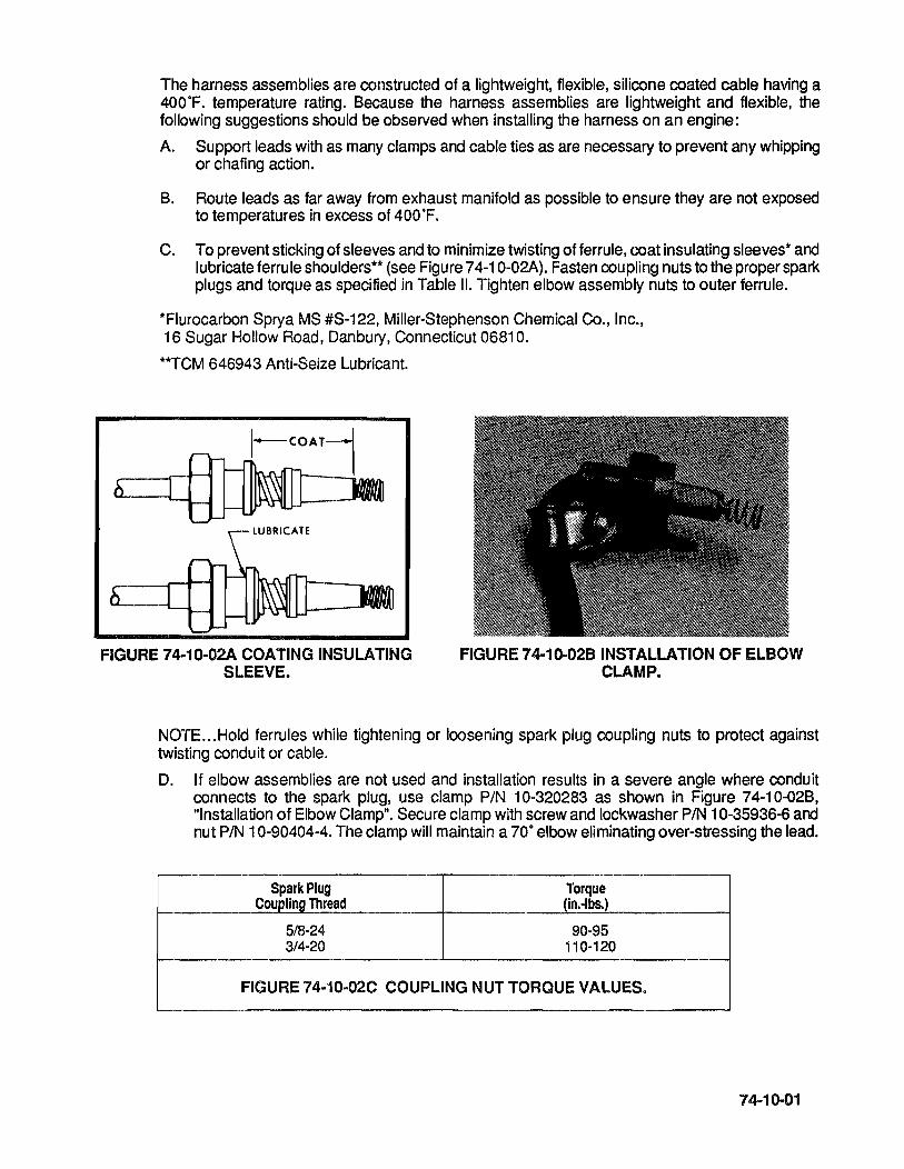
The harness assemblies are constructed of a lightweight, flexible, silicone coated cable having a 400·F. temperature rating. Because the harness assemblies are lightweight and flexible, the following suggestions should be observed when installing the harness on an engine:
A. Support leads with as many clamps and cable ties as are necessary to prevent any whipping or chafing action.
B. Route leads as far away from exhaust manifold as possible to ensure they are not exposed to temperatures in excess of 400·F.
C. To prevent sticking of sleeves and to minimize twisting of ferrule, coat insulating sleeves* and lubricate ferrule shoulders** (see Figure 74-1 0-02A). Fasten coupling nuts to the proper spark plugs and torque as specified in Table II. Tighten elbow assembly nuts to outer ferrule.
*Flurocarbon Spry a MS #S-122, Miller-Stephenson Chemical Co., Inc., 16 Sugar Hollow Road, Danbury, Connecticut 0681 O.
**TCM 646943 Anti-Seize Lubricant.
FIGURE 74-10-02A COATING INSULATING SLEEVE.
FIGURE 74-10-02B INSTALLATION OF ELBOW CLAMP.
NOTE ... Hold ferrules while tightening or loosening spark plug coupling nuts to protect against twisting conduit or cable.
D. If elbow assemblies are not used and installation results in a severe angle where conduit connects to the spark plug, use clamp PIN 10-320283 as shown in Figure 74-10-02B, "Installation of Elbow Clamp". Secure clamp with screw and lockwasher PIN 10-35936-6 and nut PIN 10-90404-4. The clamp will maintain a 70· elbow eliminating over-stressing the lead.
Spark Plug Torque Coupling Thread (In.·lbs.)
5/8-24 90-95 3/4-20 110-120
FIGURE 74-10-02C COUPLING NUT TORQUE VALUES.
74-10-01
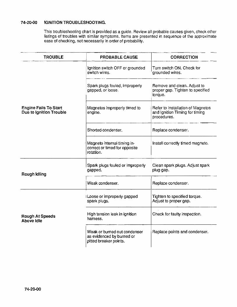
74-20-00 IGNITION TROUBLESHOOTING.
This troubleshooting chart is provided as a guide. Review all probable causes given, check other listings of troubles with similar symptoms. Items are presented in sequence of the approximate ease of checking, not necessarily in order of probability.
TROUBLE PROBABLE CAUSE CORRECTION
Ignition switch OFF or grounded Turn switch ON. Check for switch wires. grounded wires.
Spark plugs fouled, improperly Remove and clean. Adjust to gapped, or loose. proper gap. Tighten to specified
torque.
Engine Fails To Start Magnetos improperly timed to Refer to Installation of Magnetos Due to Ignition Trouble engine. and Ignition Timing for timing
procedures.
Shorted condenser. Replace condenser.
Magneto internal timing in- Install correctly timed magneto. correct or timed for opposite rotation.
Spark plugs fouled or improperly Clean spark plugs. Adjust spark
Rough Idling gapped. plug gap.
Weak condenser. Replace condenser.
Loose or improperly gapped Tighten to specified torque. spark plugs. Adjust to proper gap.
Rough At Speeds High tension leak in ignition Check for faulty inspection.
Above Idle harness.
Weak or burned out condenser Replace points and condenser. as evidenced by burned or pitted breaker points.
74-20-00
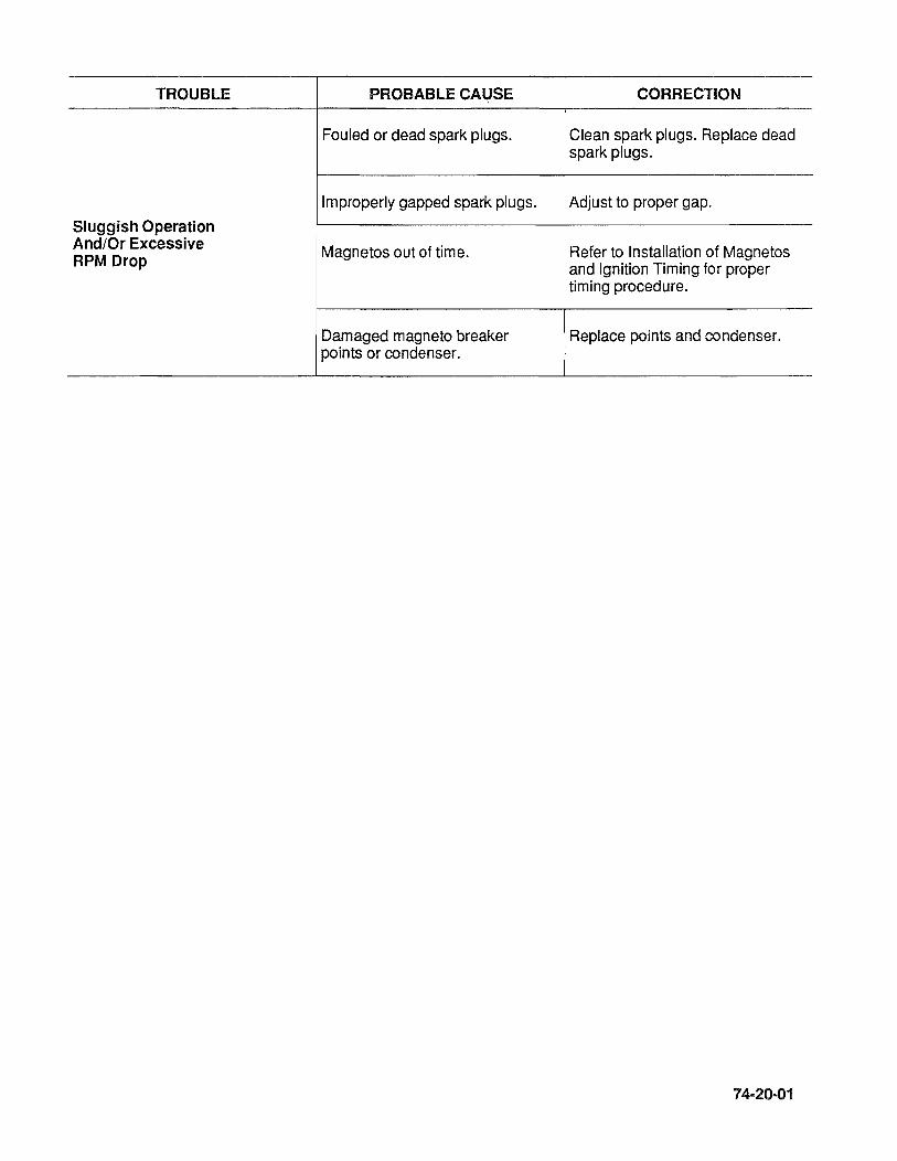
TROUBLE PROBABLE CAUSE CORRECTION
Fouled or dead spark plugs. Clean spark plugs. Replace dead spark plugs.
Improperly gapped spark plugs. Adjust to proper gap.
Sluggish Operation And/Or Excessive Magnetos out of time. Refer to Installation of Magnetos RPM Drop and Ignition Timing for proper
timing procedure.
Damaged magneto breaker Replace points and condenser. points or condenser.
74-20-01
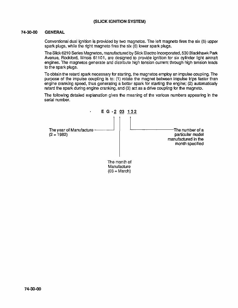
(SLICK IGNITION SYSTEM)
74-30-00 GENERAL
74-30-00
Conventional dual ignition is provided by two magnetos. The left magneto fires the six (6) upper spark plugs, while the right magneto fires the six (6) lower spark plugs.
The Slick 621 0 Series Magnetos, manufactured by Slick Electro Incorporated, 530 Blackhawk Park Avenue, Rockford, Illinois 61101, are designed to provide ignition for six cylinder light aircraft engines. The magnetos generate and distribute high tension current through high tension leads to the spark plugs.
To obtain the retard spark necessary for starting, the magnetos employ an impulse coupling. The purpose of the impulse coupling is to: (1) rotate the magnet between impulse trips faster than engine cranking speed, thus generating a better spark for starting the engine; (2) automatically retard the spark during engine cranking, and (3) act as a drive coupling for the magneto.
The following detailed explanation gives the meaning of the various numbers appearing in the serial number.
E G • ~ 03 132
The year of Manufacture ~ ~--------------Thenumberofa
particular model manufactured in the
month specified
(2 = 1982)
The month of Manufacture (03 = March)
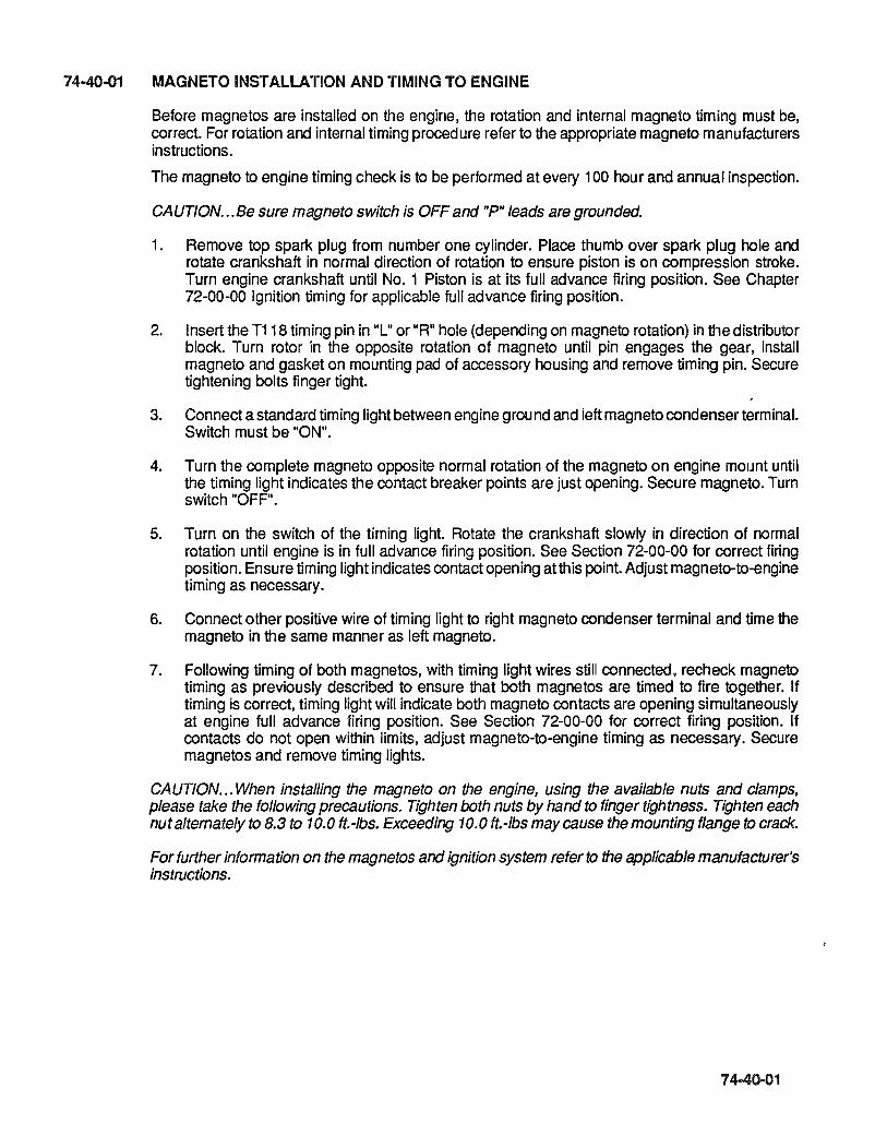
74·40-01 MAGNETO INSTALLATION AND TIMING TO ENGINE
Before magnetos are installed on the engine, the rotation and internal magneto timing must be, correct. For rotation and internal timing procedure refer to the appropriate magneto manufacturers instructions.
The magneto to engine timing check is to be performed at every 100 hour and annual inspection.
CAUTION ... Be sure magneto switch is OFF and "P" leads are grounded.
1. Remove top spark plug from number one cylinder. Place thumb over spark plug hole and rotate crankshaft in normal direction of rotation to ensure piston is on compression stroke. Turn engine crankshaft until No.1 Piston is at its full advance firing position. See Chapter 72-00-00 Ignition timing for applicable full advance firing position.
2. Insert the T118 timing pin in "L" or "R" hole (depending on magneto rotation) in the distributor block. Turn rotor in the opposite rotation of magneto until pin engages the gear, install magneto and gasket on mounting pad of accessory housing and remove timing pin. Secure tightening bolts finger tight.
3. Connect a standard timing light between engine ground and left magneto condenser terminal. Switch must be "ON".
4. Turn the complete magneto opposite normal rotation of the magneto on engine mount until the timing light indicates the contact breaker points are just opening. Secure magneto. Turn switch "OFF".
5. Turn on the switch of the timing light. Rotate the crankshaft slowly in direction of normal rotation until engine is in full advance firing pOSition. See Section 72-00-00 for correct firing position. Ensure timing light indicates contact opening at this point. Adjust magneto-to-engine timing as necessary.
6. Connect other positive wire of timing light to right magneto condenser terminal and time the magneto in the same manner as left magneto.
7. Following timing of both magnetos, with timing light wires still connected, recheck magneto timing as previously described to ensure that both magnetos are timed to fire together. If timing is correct, timing light will indicate both magneto contacts are opening simultaneously at engine full advance firing position. See Section 72-00-00 for correct firing position. If contacts do not open within limits, adjust magneto-to-engine timing as necessary. Secure magnetos and remove timing lights.
CAUTION ... When installing the magneto on the engine, using the available nuts and clamps, please take the following precautions. Tighten both nuts by hand to finger tightness. Tighten each nut alternately to 8.3 to 10.0 ft. -Ibs. Exceeding 10.0 ft. -Ibs may cause the mounting flange to crack.
For further information on the magnetos and ignition system refer to the applicable manufacturer's instructions.
74-40-01

74-40-02 HARNESS ASSEMBLY INSTALLATION.
74-40-02
Before installing harness on magneto, check mating surfaces for cleanliness. Install and tighten nuts around plate alternately to seat cover squarely on magneto. Torque screw according to magneto manufacturers instruction.
The harness assemblies are constructed of a lightweight, flexible, silicone coated cable having a 400°F. temperature rating. Because the harness assemblies are lightweight and flexible, the following suggestions should be observed when installing the harness on an engine:
A. Support leads with as many clamps and cable ties as are necessary to prevent any whipping or chafing action.
B. Route leads as far away as possible from exhaust manifold to insure they are not exposed to temperatures in excess of 400°F.
C. To prevent sticking of sleeves and to min im ize twisting of ferrule, coat insulating sleeves * and lubricate ferrule shoulders**. Fasten coupling nuts to the proper spark plugs and torque as specified in Table II. Tighten elbow assembly nuts to outer ferrule.
*Flurocarbon Spray MS #S-122, Miller-Stephenson Chemical Co., Inc., 16 Sugar HolI<?w Road, Danbury, Connecticut 0681 O.
**TCM 646943 Anti-Seize Lubricant.
NOTE ... Hold ferrules while tightening or loosening spark plug coupling nuts to protect against twisting conduit or cable.
D. Clamp harness leads as required.
Spark Plug Torque Coupling Thread (IN.-LB.)
5/8-24 90-95 3/4-20 110-120
FIGURE 74-40-01 COUPLING NUT TORQUE VALUES.

74-50-00 IGNITION TRUBLESHOOTING.
This troubleshooting chart is provdided as a guide. Review all probable causes given, check other listings of troubles with similar symptoms. Items are presented in sequence of the approximate ease of checking, not necessarily in order of probability.
TROUBLE PROBABLE CAUSE CORRECTION
Ignition switch OFF or grounded Turn switch ON. Check for switch wires. grounded wires.
Spark plugs fouled, improperly Remove and clean. Adjust to gapped or loose. proper gap. Tighten to specified
torque.
Engine Fails To Start Magnetos improperly timed to Refer to Installation of Magnetos Due to Ignition Trouble engine. and Ignition Timing for timing
procedures.
Shorted condenser. Replace condenser.
Magneto internal timing Install correctly timed magneto. incorrect or timed for opposite rotation.
Spark plugs fouled or improperly Clean spark plugs. Adjust spark
Rough Idling gapped. plug gap.
Weak condenser. Replace condenser.
Loose or improperly gapped Tighten to specified torque. spark plugs. Adjust to proper gap.
Rough At Speeds High tension leak in ignition Check for faulty inspection.
Above Idle harness.
Weak or burned out condenser Replace points and condenser as evidenced by burned or pitted breaker points.
Fouled or dead spark plugs. Clean spark plugs. Replace dead spark plugs.
Sluggish Operation Improperly gapped spark plugs. Adjust to proper gap.
Magnetos out of time. Refer to Installation of Magnetos AndlOr Excessive RPM Drop and Ignition Timing for proper
timing procedure.
Damaged magneto breaker Replace points and condenser. points or condenser.
74-50-01

74·50-02
INTENTIONALL Y
LEFT
BLANK
CHAPTER1S AIR
75-00-00 GENERAL
75-00-01

75-00-02
INTENTIONALLY
LEFT
BLANK

75-00-00 GENERAL
The induction system components include the aircraft filter/alternate air door, airframe to throttle ducting, throttle, manifold, balance tube and cylinder intake ports. Air flows through these components in the order they are listed.
Refer to Pilot's Operating Handbook for alternate air door operations.
The induction manifold is an air distribution system mounted in several different configurations according to engine model. It serves to carry induction air to the individual cylinder intake ports.
The cylinder intake ports are cast into the cylinder head assembly. Air from the manifold is carried into the intake ports, mixed with fuel from the injector nozzles and enters the cylinders as a combustible mixture when the intake valve opens.
75-00-03

75-00-04
INTENTIONALL Y
LEFT
BLANK
CHAPTER 76 ENGINE CONTROLS
76-00-00 GENERAL
76-00-01 CRUISE CONTROL BY PERFORMANCE CURVE
76-00-02 CRUISE CONTROL BY E.G.T.
76-00-03 PERFORMANCE CHARTS
76-00-01

76-00-02
INTENTIONALL Y
LEFT
BLANK

76-00-00 GENERAL
The curves in this chapter represent uninstalled performance and are provided as a reference in establishing power condition for takeoff, climb and cruise operation. Refer to aircraft manufacturer's flight manual for tabular climb and cruise data.
76-00-01 CRUISE CONTROL BY PERFORMANCE CURVE.
1. Set manifold pressure and RPM at cruise power selected.
2. To determine actual horsepower, employ the following procedure:
A. Correct horsepower for inlet air temperature as follows:
(TS = Standard Altitude Temperature)
(1) Add 1% for each 10· F belowTS.
(2) Subtract 1 % for each 1 O· F above TS.
3. IO-550-E, F & L engines are equipped with altitude compensation fuel pumps which automatically provide the proper full rich mixture at any given altitude. Adjust mixture to lean out fuel flow for cruise settings according to applicable fuel flow vs. brake horsepower curve.
4. 10-550-D engines utilize a manual mixture control.
CAUTION ... When increasing power, enrich mixture, advance RPM and adjust throttle in that order. When reducing power, retard throttle, then adjust RPM and mixture.
NOTE ... It may be necessary to make minor readjustments to fuel flow (mixture) after changing RPM.
76-00-02 CRUISE CONTROL BY E.G.T.
If exhaust gas temperature indicator is used as an aid to leaning proceed as follows:
1. Adjust RPM for desired cruise setting.
2. Slowly move mixture control toward "lean" while observing E.G.T. gauge. Note position on the instrument where the needle "peaks" or starts to drop as mixture is leaned further.
3. For the maximum recommended cruise setting see Operating Test Limits (72-70-14C).
CAUTION ... Do not attempt to adjust mixture by use of E.G. T. at setting above 78% of maximum power. Also, remember that engine power will change with ambient conditions. Changes in altitude or outside air temperature will require adjustments in manifold pressure and fuel flow. (Refer to Charts Fuel Flow Vs. BHP).
Gauge fuel flow should fall between the maximum and minimum values on the curve. If not, the fuel injection system or instrumentation (including tachometer, manifold pressure, fuel flow gauge or E.G.T. system) should be checked for maladjustments or calibration error.
76-00-03

76-00-04
INTENTIONALL Y
LEFT
BLANK

76-00-03 PERFORMANCE CHARTS
The following performance charts are classified under figure 76-30-00.
TITLE
Metered Fuel Pressure Vs. Fuel Flow IO-550-D&E
Metered Fuel Pressure Vs. Fuel Flow IO-550-F&L .
Fuel Flow Vs. Pressure Drop IO-550-D,E,F&L . . .
Fuel Injected Fuel Pump Inlet Pressure-PSIAVs. % Rated Brake Horsepower IO-550-D,E,F&L . . . . . . . . . . . . . . . . . . . . . . .
Sea Level Performance Curve IO-550-D.E,F&L . . . . . . . . . . . . .
PAGE
76-00-06
76-00-07
76-00-08
76-00-09
76-00-10
Sea Level Performance & Altitude Performance IO-550-D.E,F&L .......... 76-00-11
Fuel Flow Vs. Brake Horsepower IO-550-D&E .
Fuel Flow Vs. Brake Horsepower IO-550-F&L .
Automatic Compensation Full Throttle Flow IO-550-E,F&L .
Mixture Ratio curve 55% Power IO-550-D&E
Mixture Ratio Curve 55% Power IO-550-F&L
Mixture Ratio Curve 65% Power IO-550-D&E
Mixture Ratio Curve 65% Power IO-550-F&L
Mixture Ratio Curve 80% Power IO-550-D&E
Mixture Ratio Curve 75% Power IO-550-F&L
76-00-12
76-00-13
76-00-14
76-00-15
76-00-16
76-00-17
76-00-18
76-00-19
76-00-20
100% Power Fuel Pump Pressure Limits IO-550-D,E,F&L ............. 76-00-21
Fuel Flow Limits IO-550-D,E,F&L. . . . . . . . . . . . . .
Maximum Allowable Collar Oil Leakage IO-550-D,E.F&L .
100 AMP 24 Volt Alternator Performance
60 AMP 24 Volt Alternator Performance .
76-00-22
76-00-23
76-00-24
76-00-25
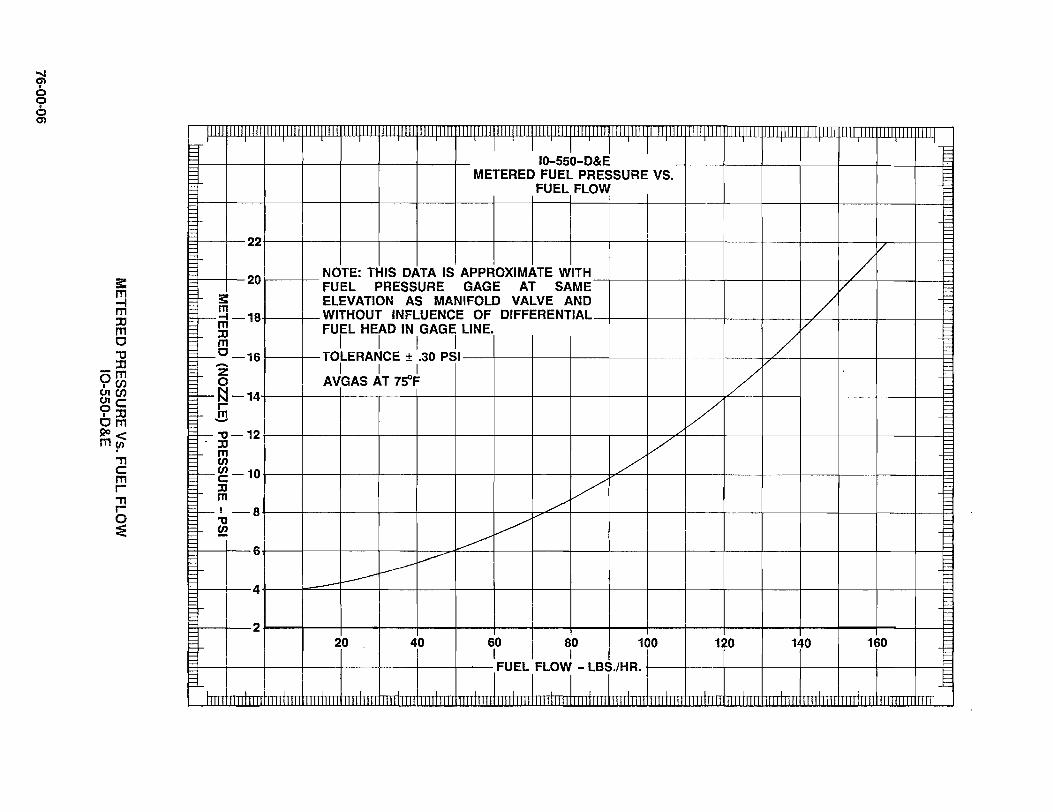
~ o o 6 en
!l:
~ ::xl m o "tI ::xl -m
°en &.en Ole: 9::xl om ~< my>
'T1 e: m r 'T1 r o :e
11111 1111111111 1111111111
22
20
:: m
1---4 -18 m :0 m
1--°-16 -Z 0
1--~-14 r-m -1--" -12 -:0 m en
I--~ -10 :0 m
,--1-8
" ~ 6
4
2
f-
1111111111 1111111111 1111111111 1111111111 11I1I11I1111111111111111111111II1I1H1 TTl III II 1I11T1 ! 11111 1I1UIIII I111111111 I111111111 1111111111 III I I 10-55~-D&~ I F
t;: METERED FUEL PRESSURE VS. == FUEL FLOW == = =
f= i= i= i=
V i=
/ i= NOTE: THIS DATA IS APPROXIMATE WITH 1= c:: FUEL PRESSURE GAGE AT SAME V 1= ELEVATION AS MANIFOLD VALVE AND / c::
= WITHOUT INFLUENCE OF DIFFERENTIAL = FUEL HEAD IN GAGE LINE. V =
I I I I / = = TOLERANCE ± .30 PSI ==
I I I /v == E AVGAS AT 75'F E
~
V i= i= i= ~
V F=
/' i=== F= r=
V i=== :::: /""
E ==
~/-y E ==
~ == == --- = ~ ==
~ = - == E i=== F ~ 1=
20 40 60 80 100 120 140 160 1= I I E
IFUEL,FLOj - LBj.lHR. E = ==

~ ({> o o 6 ~
s: m ~ :XI m c
" c m I
-"'0 0::n cnm CJ1C/) OC/) ';'c I(o::n 1m ~ . " c m I
" b :E
IIIl 11TTTmT TIm 11111111 11111 f= I I I I I I -§ 10-550-F&L t::: METERED FUEL PRESSURE VS. ~ ruaFww -t= 22 I I I
I 20 NOTE: THIS DATA IS APpJOXIMtE JTH / t= FUEL PRESSURE GAGE AT SAME V 1= ELEVATION AS MANIFOLD VALVE AND / 1= 18 WITHOUT INFLUENCE OF DIFFERENTIAL-+_-+_-+_-+_-+_-++---+_-+_---+_-R ~ FUEL HEAD IN GAGE LINE. V ~:5: I I I I / ~f--m - 16 TOLERANCE ± .30 PSI-_I_---Ir----+_--l---+---t--+__-~~-+--_I_-----jl__-+_--R
~ I I I V ~ AVGAS AT 7ftF
f--~-14 V ~f--~-12 ./
~ ~ ~v I-'- ::0 f--m-104--_+_-_+---f---+---l---+---t--+-~~-_+_-_+----~--+_--~--_I_-__I--+__~
~ - /V f--~--8 ~
1-~f-6 ~ ~ I---l---
R-~-I-- 4 I---
~-b-2~--_+--_4----~--+_--~--_+--~1__--+_--~---+--_4----+_--~--~--_+----~--+_~
20 40 60 80 100 120 140 160 I
R--+---+----+---I---+----lf---+---+_ FUEL FLOW Ib./hr.--I---+--+--~--I---+--4----jI----!=1
1= L E
11111 1111111111111111111111111111111111111 1111111111 111111111111111111 II 1111111111 III III 11111111111111111111111111111111111

1:::' I
E ~ t=: E
300
250
200
Ii :::t:
Ui 150 m ...I
3:: 0 ...I LI. ...I. W ::> 100 LI.
/
-50 / I
1= I 1= 1= 1= 1=-0 1= 1= 0 .5 1= f:: 1= 1= 1= r= E r=
76-00-08
,
AvbAS _)5 0
I0550D,E,F,L FUEL FLOW VS. PRESSURE DROP
!
I I I
./ /
/ /
/' V
V / I
MAXIMUM PRESSURE DROP ALLOWABLE
/ ACROSS A SUITABLE FLOW TRANSDUCER
/ /
/
/
1.0 1.5 2.0 2i5 3
iO 3.5 4.0 4.5 5.0 5.5 6.0
1111111111
PRESSURE - PSIG I
III LI Lilli lJlll 11+1 11111 Illlilill 111JIlIIII
FUEL FLOW Vs. PRESSURE DROP IO-550-0,E,F&L
1I
= == == == = == = = == == == = t= ~ = t= 1= r= 1= 1= E r= 1= E E ~ t=: E E ~ t=: F F 1=
t= E 1=
6.5
I 11111

« c;; ~ 50 w a: :::> en en w g: 40
~ z a. :E 30 :::> a. z o i3 ~ 20 ~ ..J W :::> LL
10
r .! J 10-5fO-D,~,F&L E
FUEL INJECTED FUEL PUMP INLET PRESSURE - PSIA
VS. %RATED BRAKE HORSEPOWER
110' F AVGAS
FUEL FLOW (LB.!HR.) = % BHP X RATED FUEL FLOW
l\\ 1\\ 1\\ 1\\ 1\\ 1\\ 1\\ I\~ ~~ ~ l\\ l\ \ I\MANUAL MIXTURE\ ~\ \l\ \~V ~ONTROL REOUIRE[ f<,~v')<
,\ \ r\\ \ \ \\ \l\ \l\ \~~f2 f\\\ f\\\ ~\ \\ \\~f?s:&~ f\\\ ,,\\ ~\J~~1>s~~~ ~ ~ k5 K>' ~ ~ ~ R R ~ ~
~KR5·k>~ BOOST FOR VAPOFf:< ex ~UPPRES§.!ON ..l PR~ING.x UI
, >< A;><-~~/<~
c :::>
/ ,60ST PUMP OPERATION ... RE0I'RED, I
II,//vi r-,. ./ 5 «~ .IT ITm1
IDLE 20 40 60 80 100
% RATED BHP
FUEL INJECTED FUEL PUMP INLET PRESSURE PSIA VS. % RATED BRAKE HORSEPOWER IO-550-D,E,F&L
SEA LEVEL
10,000LEV
20,000LEV
76-00-09
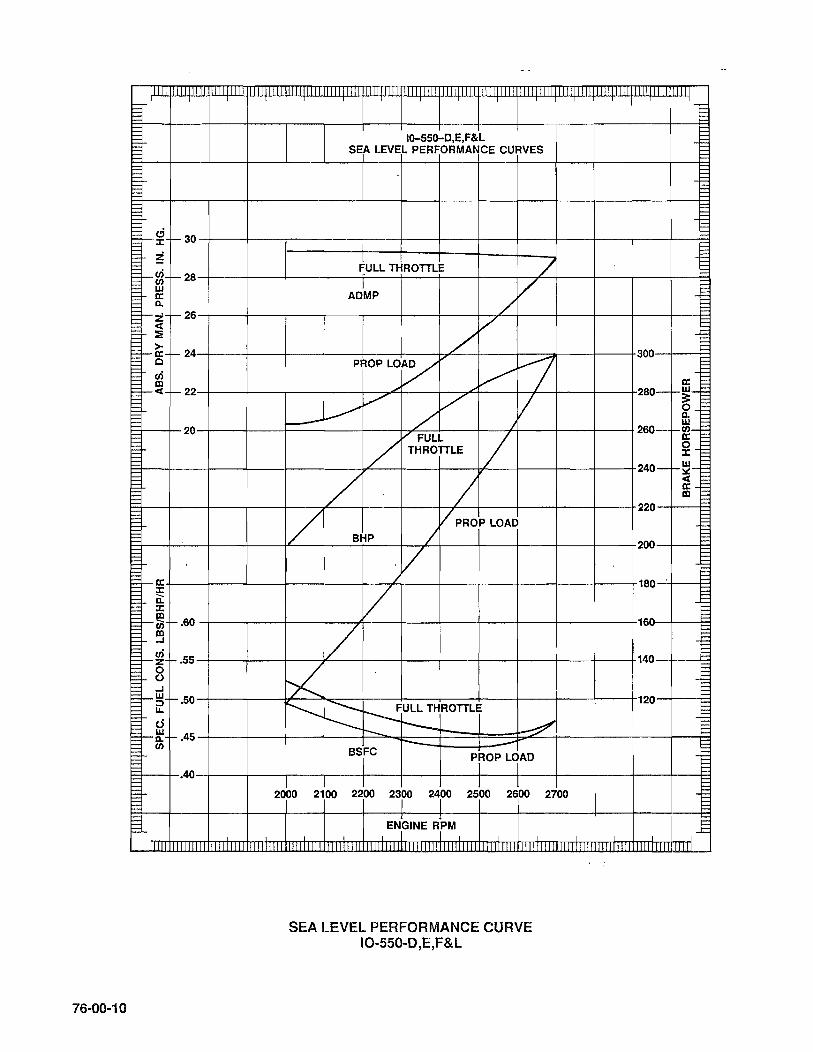
WJI II Lilli II WJLIlllJ
t= E E F f-g F -30 t= t= ~ F t= i-en t= -28
b (f)
'E w E 0: E a. F r-z -26 = ==
< ==
:: == >-= -0: r- 24 = c E en == = IX!
== 1-< I- 22 E
== == :::: 20 = = = ~ = = = == =, = = == = = = E =-0: == J: = Q: = J: = IX! =1--- r.60 = (f) = IX! = ..J = . ==-~ r.55 = 0 == 0 == ..J =_w r.SO = :::) = II.
== d = ==-~ r .45 E en E = :::: .40 == == == :=: == ==
76-00-10
111111111 UIIIIIIII 1111111111 111111111 1111111111 111111111 1111111111 1111111111
IO-SSO-D,E,F&L SEA LEVEL PERFORMANCE CURVES
FULL THROTTLE / AD1MP
/ V
/ V
PROP LOVV" /V r7
V V V ------ / - /
V FULL / / THROTTLE
/ / i/ / PROP LOAD
I BHP
'/ /
/ /
V ~ ---~ULL THROTTLj r-- ~ -- ---- -BSrC prop L~AD
2000 2100 22'00 23rO 241
00 25~0 2doo 2700
EN,GINE R;PM
SEA LEVEL PERFORMANCE CURVE 10-550-D ,E,F&L
I I
1111 1111 I Llil -
E t= E E ~ t:::
E F 300
0: 280-f-~-
== 0 a. w 260-f-~-
0 J:
240-f-~-< ~-
220
200
180
16~
140
120
I I
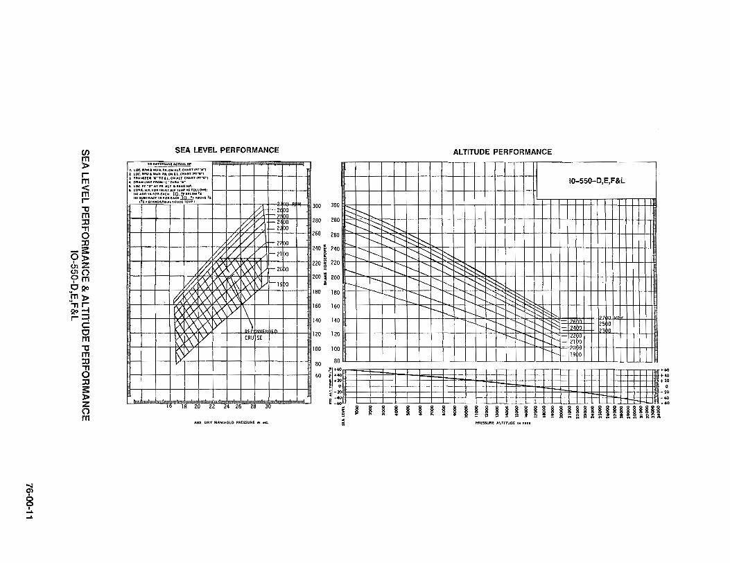
~ o o • .... .....
en m » r m < m r "tI m :0 ." o :0
-5: 0» '::;;:: ~o ?m 0120 m» ...,,~ 120_ r-l
c: o m "tI m :0 (3 :0 5: » ::;;:: o m
SEA LEVEL PERFORMANCE
TO on.""""". ACTUAL"
,. LOC''' ...... MAH ... ,..OHALT.CHAIIITln-.-1 :L LOC. IIt,...I. ..... H "'. ON '-L. CHAllT ,n,·, :I. TItA14fllt ..... to '-L.ONALT.CH"'" I"·C"J .. OllA" 1.1"". "'OM -C" THItU -A-I. lOC n-v'AT '" "LT .• 11(1.0 H." . .. COIlUilL H .... fOil'llNUT AIIII n ...... A$ 'OLLOWS,
:::::r~~~~::~: ~~m:.:~V( lS tTS·STAHO ... ADALTITUDI TIM',
~ '-2 ~g !-2
~ V '-2 0 '-2 0
~ Vjl/ !-2 0
~ VV f-21 0
~ ~ K>< K>( t'\V f- 2( 0
ki( ~ KX ~ ~ V f-19 0
~ $X \X ~ ~ tv P< >0< )X )(\ y \ X >0 >0 y \ ,n A )(\ Y CRU SE
~ Y
lR ?O ?? ?4 ?~ ?R ~o
ASS DRY MANIFOLD PRESSURE IN. HG.
300 300
280 280
260 260
240; 240 g
220 ~ 22
200 ; 20 :i
180 18
160 16
140 14
120 12
100 10
8
;: '-. ~t---:-r:::: ~
------I'---...
----.....
I'---r-..... -.......
'--... --....
---r--
~ ::--... .......... ~ ~ ~ .........
.......... ~ ~ 3:2 ~ -..... .......... "-... I'---
-.... ......... ~ :- r--..
"-... -..... ~
......... '----.......... r-.....
r-- -... "-... "---.... I-... r--... --- -.......
.........
ALTITUDE PERFORMANCE
10-550-D,E,F&L
...... S:: -.....; ~ :::--.. ......... ~ ~ ~ ~ r-..... r----. ......... i'- ::::: ~ ~ " t---- ~ ~ r--... "- -...
r----. i' ~ [:§ ~ r--- ......... I': :::-.--r--- ..........
-... ......... r---. r::: f'-i' :::::: 25 0 -..... r--- i'- - 24)0 23bo r--.. r--.. r---~ I' "- W~ r--.. " I-
"- lO -... 19 0 80
60
:~IIIIII n IIIII H Ilia tWJIJltlI[~ ~ ~ ~ ~ ~ ~ ~ ~ ~ ~ ~~~~I~~~~~~~~!i~IUlHHi = PRESSURE A\.lITOO£ IN flU
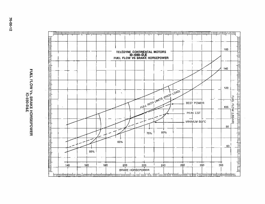
at • o o • .... I\l
" c m r-
" r-o :E
-< o!'l enOl (.11:0 <?l> Or: ~m m:r:
o :0 en m
" o :E m :0
11111 111111111 1111111111
~
... ~
-' ..-
-~ 140
,111111111 111.111111
~ -----v-~ -,..-
~ I . 55%
160
1111 IHI! 1111111111 1111111111 1111111111 111111111 ,111111111 111111111 111111111 1111111111 1111111111 III lllWlillil i 111111111 111111111 11111
F ~ 1= 1= f:::
160 1= TELEDYNE CONTINENTAL MOTORS
lo-S5O-0,E / FUEL FLOW VS BRAKE HORSEPOWER
/
VV / 140 1=
V / f:::
/ f::: ./ 1=
1= V V
V f:::
~ f:::
120 f::: f:::
V/ \ \..0£>-\)\ V f::: >~ ~
~ :,\S\?\,-O? L -n f::: S-~
K ~\..\~\ ~I-" BESi POWER
~ l= ~ \,-\G ~.........-: -n t===
-- ~\J\..\.. ~ 100 r t=== q-I:::
~ .-- ~ L PEAr EGT
~ 1=
~ ~ t= -7 r f:::
l"...- eo 1= ~/ ~-t=== v V-..- ..- / I 1= - MINIMUM BSFC JJ t=
~ ..... n ~ t= .... -~ 80 ~
f.--J .......... ~ --- t=
V-- 80% t=== f-~
75% E= t= ~ t=
65% t=== 1= 60 t=
t=== t=== F ~ 1= t= F
180 200 220 240 260 280 300 1=
BRA~E H07SEP01ER
11111
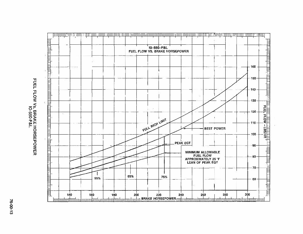
~ 8
I .... W
"TI c: m r-"TI r-
~ <
-(f) o· o,tD 01:JJ <?l> "TIA Qom r::t:
o :JJ CJ) m "C o :E m :JJ
~ II 111111111 11111"111111111 1"1'11 'I" "1" 11 1"" I ""IIIITIIIIJll"111111111 '1"1 '1"1 'I" III' I I JlIIIITfIIIfIIIIlIill I'IIlIIIIll"II!, "'1"111"11111"1" I '1"111"11111111""1" III' 1111
IO-550-F&L F FUEL FLOW VS. BRAKE HORSEPOWER
1
Ij i 160 I 0
~ 150 I 0
tJ I I I I I I I I I I I I I I v~/1 140 I n
1=1 /' / 130-+--+= H V V
1=1 I I V V 120 ~ H V V - S
-r.0~~ V / 110 ~ <r-'C'/ I
1(U\"'V -./ 1./ BEST POWER Iii 1=1 ~~ ~ (f) H , ~ .,./ 100 :i: VV' V ;lJ
I=l I I I ~./ v--- PEAK EGT H ______.,.,... ~ 90
___ V- ,~V__ ___ I-" MINIMUM ALLOWABLE ........- ~ ..- FUEL FLOW 80 -+---I~
~ I ___ ~ ~I _----- APPROXIMATELY 25 OF I ___ ~ .,.,--___ ~I· LEAN OF PEAK EGT
1=1 ~~ ---- _ 0 H ;;;0'" ~ ~ I 7-+-~
~~I ~ 55% 65% 75% 60 -+---I~
!-
I 140 I 160 1 180 I 200 I 220 I 240 I 260 I 280 I 300 I 11111111 II III II III II I "lllIllllllllIllIJIlIII" III" 1111111 III 1I1I" II Ii I U . ~~~':<:~ .. 1;I.9.~~.~.~R.~~~ III Ii 111111111111111111111111111111111111111111111111111 " 11111111" II " III
1=
~ ~
.§

U Lll
t= f= f= t= t= l= t= ~
100
~ -90 0
..J II.. ..J w => -80 II..
::t: ()
a: -70 ..J ..J => II.. II.. -60 0 l-z w -50 () a: w c. ,
40
30
20
10
l-
E
1111 11I1I1111 111l11UJ I
76-00-14
ilL ILlIL .U III II .IIIIJl UIIIILLlJ llUllllll
10-550- E,F&L
AUTOMATIC COMPENSATION
FULL THROTTLE FLOW
i ;
I I I
............... ~~
............ ~
i'..... .........
~ '-..... ~ ~
,c.
0 2 4 i i 11 12 14
1111111111
ALTITUDE X 1000 , ,
IIIlIIlLU 1I1II I 1I I ,IIIIlIlIl 1IIIIIIll IlIIIIIII
AUTOMATIC COMPENSATION FULL THROTTLE FLOW IO-550-E,F&L
...............
16 18 20
LIIIIII
IIIIII
F ~ f= t=
f= t== F f= f= f= f= ~ f= f= t= i=
:= E E f= i== E E ~ i== F F ~ f= t= f= ~ t= t= t= f= i== E E ~ i== f= E tg f= f= f= ~ t= f= f= f= f= t= f= f= E E E f= i== E E l= i== E E ~ i== E
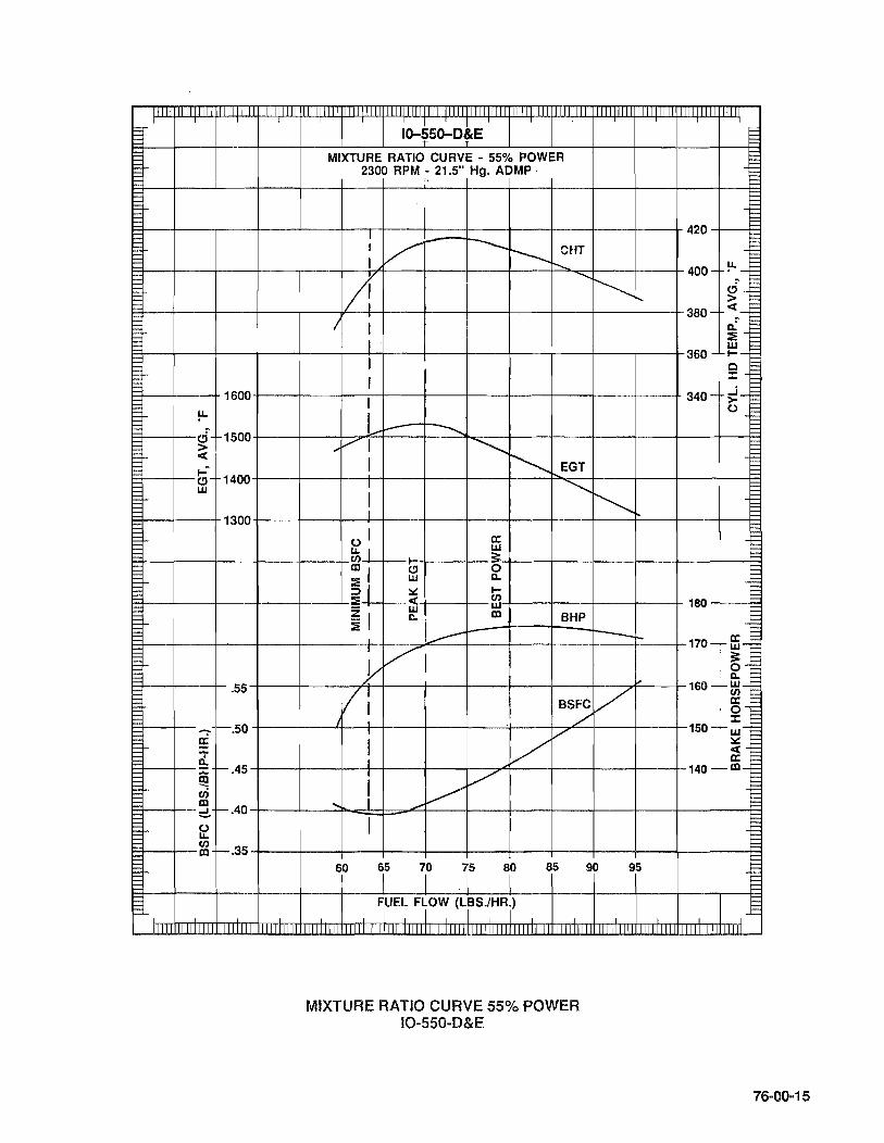
I
F 1600 E E !J.. F 1= ci 1500 E > E < F 1= I-~
t- e) 1400 w
1300
.55
~ 1-.50 5 ... Q. = 1-.45
I-~ cri IXl
f-.40 ::::!.. t- O u.
C/) f-.35 IXl
I-
J...
IIIII IIIII
10-~50-DlE MIXTURE RATIO CURVE - 55% POWER
2300 RPM - 21.5" Hg. ADMP .
I I V --~ CHT I r-.....
II! ~
~r-. I I
I J
r I
L I- -..... ... VI --...........
~ I EGT I "'-..,
! ~ 0 1 a: ~I
w I- 3:
il e) 0 W Q.
::.:: I-:E < C/)
w w
~I Q. IXl BHP
---- --!-I V }
II, V BSFC ./ •
! V [?"
I V I V ... .-
I
60 i5 7
1
0 .r 8t 85 90 95
F1UEL F10W (LrS.lHRj)
MIXTURE RATIO CURVE 55% POWER IO-550-0&E
,
F F l=:: F 1= E E
420 1= t::::: E F
u. F 400- . -E
~ F ci E > F F
380- <-E :' F Q. F :E F w F
360- I--t=: o !== = j:: ·F
340- -'-F >- F o !== l=:: 1= !==
180
170-- ffi-3: 0 Q.
160--m-a: 0 :r:
150-I-w-::.:: < a:
140 - t- 1Xl-
t-
t::::: E rn 111111
76-00-15
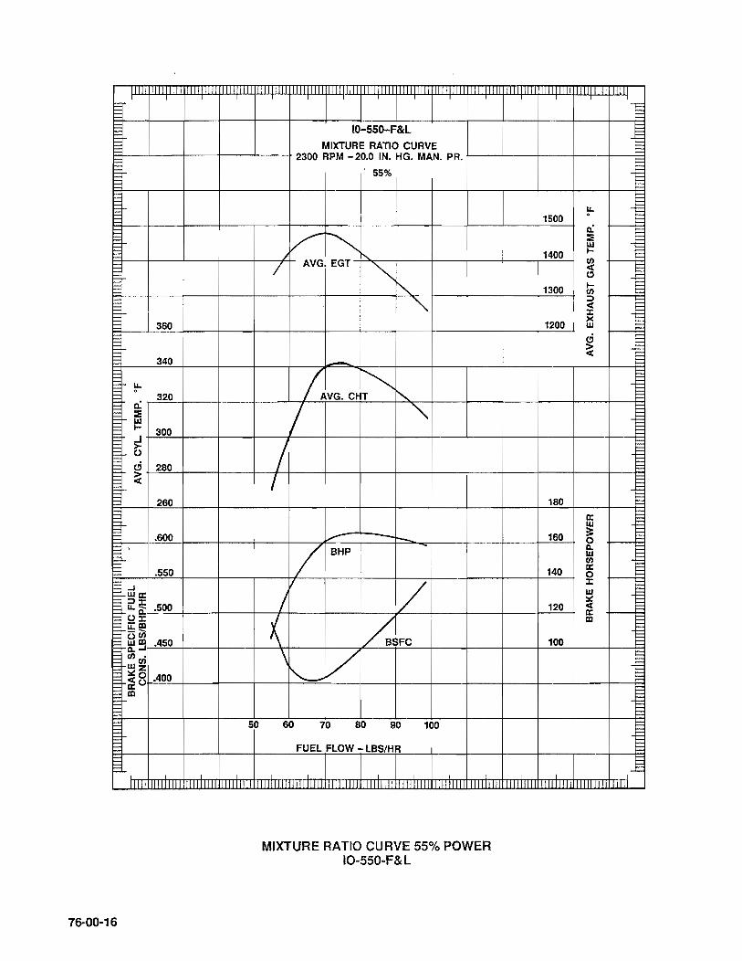
I I
360
340
u. 0
1= 320 1= 0: 1= :: 1= w 1= I- 300 1= 1= .J 1= ~ 1= 1= ci 280 1= 1= ~ F= 1= ~ 260 1= 1= 1= ~ .600 1= 1= 1= ~ .550 1= 1= ....J
wo:: 1= ;:):r;
u.a: .500 1= 1= O:r; 1= -m 1= !::(j) 1= Om .450 1= ~....J 1= 0· E W
0 :.::Z «0 .400 0::0 m
50 I-
76-00-16
IO-550-F&L
MIXTURE RATIO CURVE 2300 RPM - 20.0 IN. HG. MAN. PRo
55% I
I i i
V~ / "-
/ AVG. EGT
"" t"'-. '" -
IAVG.CH~ t'-... V '" /
I
,.- -10-
/ BHP
I
/ /
~ /.SFC
\ V ~-
60 70 80 90 100
FUEL FLOW - LBS/HR
MIXTURE RATIO CURVE 55% POWER IO-550-F&l
E ~ t= E E ~ r-
u. 1500
0
0: :E w
1400 I-0 « (!)
1300 I-0 ;:) « :r;
1200 >< w ci > «
t=:: t=:: t:: ~ 1= 1= :::
180 s: 0:: 1=
1= w 1= 3: 160 0 F Il. 1= w 1= 0 1=
140 0:: ~ 0 :r;
E W :.:: 1= 120 « 1= 0:: m 1=
1= 100 1= 1=
t=:: E E ~ t=:: E E ~ 1= 1= F ~ 1= E
rmT rmmm nm
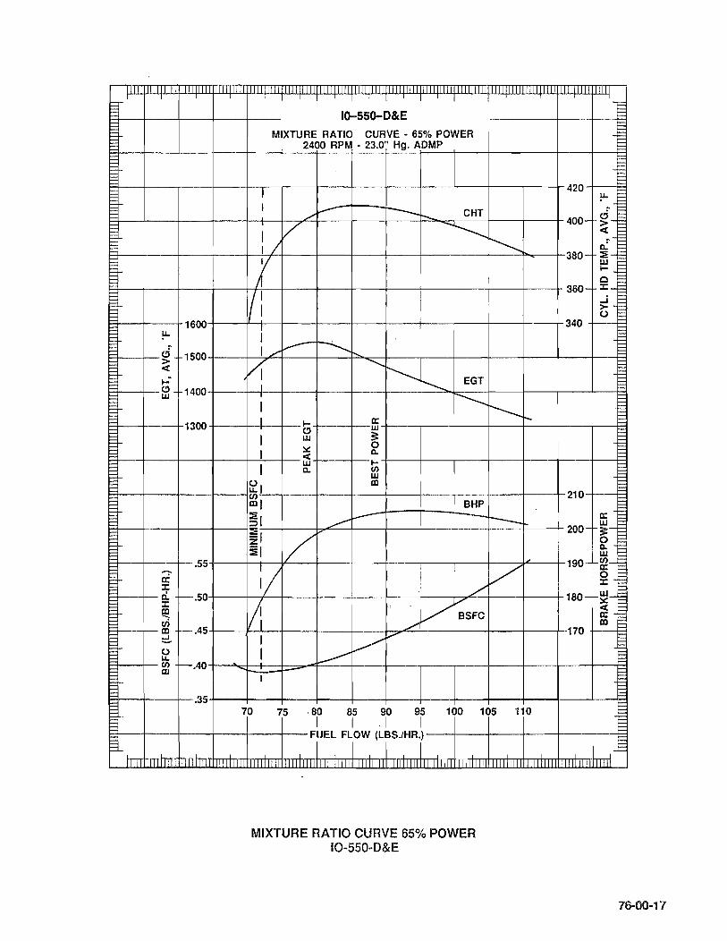
I I I I I I I
ID-SSD-D&E MIXTURE RATIO CURVE· 65% POWER
2400 RPM· 23.0" Hg. ADMP
1I I
i= i= i= r= Fr--_�_---4----+----+~--+_--_r----r_--~--~----+_--_r----r_--_I_420~~~
I ~ i= ~ ~
/~ --......... CHT d_t::: ~--~---4----+----+-+1--+~~~~--~--~~--~~-~"-----~--~--~400- ~ ~
-..........~ ~t::: I / 0.: t:::
~--4_--_+----~--+-~~----~--4_--_+----~--+_--~--~~--+_380- ::-t:::
1 wE I- ~
r= 0 ~ F~~~----4---~----+I/77:--~--~----r---~--~----+---~----r---~360- g-I FI-~_4----+1600~--~-+--+---~----r---~---4----+----+----t-·---r340
,! ~ t::: . t::: u.
~--~_ci 1500~--_+~,~~~~--_4--"'--~~~--~----~--4_--_+----r_--4_--E3r= ~ VI ""'~
E~T-~--§~ 1400~--_+-+_I_+----~--~--~~--,~--~~E-G-T_+----~--~--~--~ I -----r---r--
8--4_--+1300 +--~_II~4__1- +----+--ffi +--+----+_--~----r_--~-_4-_B I ffi s:
::.::: 0 I « Co
Er--~--~----~---+~--+--w I-+---+----+_--~----r_--~--~--_B I c. (J) w
fe, lXI ET--~--_+----r_--'(J)~~----~--~---4----+----+----r---~--~-210-r--~ ~ lXIl BHP
~, _____ ~ --- ffi ET--~--_+----r_--,-~~----~~~--_;----+_--_+----r_--_r--__r200- >-
~I / 0 ~, ~ ET--_r--~~.55+----+-r-I-¥----r----I----;----+----+----~--~~~--~190- ~-
i II // ~ F+--i-- r:i.. -.50-t---+-f--+----+----~---r---;--+V~"--+---~---+ 180- ~-
~ !II, /' BSFC ~ I- ui Iii ../ lXI 1-1:::+_-1-- lXI r-- .45+_--f--'--t----t----r_--t,--:::7" ...... """'-+---+--+---_r-~-170 +_-f=3 E ~ I ~~ ~ fe I ~ I-i=+-~~~ r-.40t-~~~==~~_F~--r--~--_i----t_-_t----t_--_r--_1--~ i= I i= ~--~---4--.35+---_+----t----~----~--4_--_+----+_--~----~--~--_4--~
70 75 80 85 90 95 100 105 ·110 I I . I I
I:::j---j---_+--r---t---+- FUEL FLOW (LBS.lHR.) --~--+---~-~---+-----j=t
I I I I iJlJlJlIIIIllUl1l1l1111111 111lll
MIXTURE RATIO CURVE 65% POWER IO-550-0&E
J
76-00-17

I I
I-I::::
420 1= LL. 1= . ~ 0.: 400
:!iE UJ l-0 380 et UJ ::t:
l- ..I ~ 360
~ 340
t-
..J .700 UJa: :::t::r: LL.a: O::r: i:i:!;!! .600 -C/) Om ~..J c/).
.500 UJC/) ~z et° a: 0 III .400
1= 1= 1= 1= 1= ~ 1= F
j 11111111
76-00-18
I I 10-550-F&L
MIXTURE RATIO CURVE 2300 RPM - 23.0 IN. HG. MAN. PRo
65%
~ r-......
1/ AVG.EGT ~ ~ ~
........ ~ ~ / '" I '" ~ AVG.CHT
1/ ~ I "-
/ "'" / / V- BHP --/ --
/ /' / /'
hi V VBSFC
'" V V
60 70 80 90 100 110 120 130
FUEL FLOW - LBS/HR
I i
MIXTURE RATIO CURVE 65% POWER IO-550-F&L
IT ',-
I:: F= t::
1600 r= F LL. r= . t::: a.: t::: 1500 :!iE r= t::: UJ t::: l- t::: C/) t::: et 1= 1400 " t:::
l- t::: C/) t::: :::t 1= et 1= 1300 ::t: 1= >< 1= UJ F ci F 1= 1200 ~ F F r= F F r=
t::: t::: t::: ~ t::: t:::
220 t::: t::: t=
a: 1= UJ 1=
200 ::: 1= 1= ° 1= D. 1= UJ C/) F
180 a: 1= ° 1= ::t: 1= UJ F F
160 ~ F et F a: r= III 1==
140 E f:: 1== F j::: ~ F F= 1= ~ E
~
ITTl 111111

I
1= 1= f=:
1600
~ !.L.
f=: ci 1500 > 1= < 1=
1= ..: 1-1400 f=: " 1= w 1= § f=: 1300 1= 1= § f=: 1= 1= § f=: 1=
...... r.55 a: ::t: D. ::t: ;-.50 fe en IXI do 1-.45 0 u. II) IXI 1-.40
r:= E .35
I I 10-5S0-0&E I I I MIXTURE RA no CURVE· 80% POWER
2500 RPM· 25.5" Hg. ADMP
I : I I--- I --- CHT
I V -r---1/ I r---I-
I;{ I I
/ I I I I I I
Y V -.... r-J I I
------./ EGT r---I I r'-
I I r---. I I 0:1 r--I W
0 1 ~I I-
~I Cl 0.1 IXI W
l-
::1 ~ IDI < ~I w IXII 0. Z BHP ::,
V ~I - r---I
t-
V I r I 1/
Vi I ./ I I ,/ ,
,/
I 1 ~ I 1 ~
I ~ ESFC
1 --( I --- -- I I
85 90 95 1,0 1rs 1t 115 120 125
FUEL FLOW (LBS.lHR) I I I
ill Jlilllill
MIXTURE RATIO CURVE 80% POWER IO-550-0&E
Wlllill
III III II
= == ::::: == = == f= := := §
440 u. ~ . := ~ :=
f- ~ ~ 420 < en
400-f-o. :: w I-
380-1-0 ::t: ..J >-
360-f-u
250 1--0: w 3: O
240 - 1--0. w en 0: 0
230 I--::t: w ~ <
220 _0: IXI
-.l
76-00-19
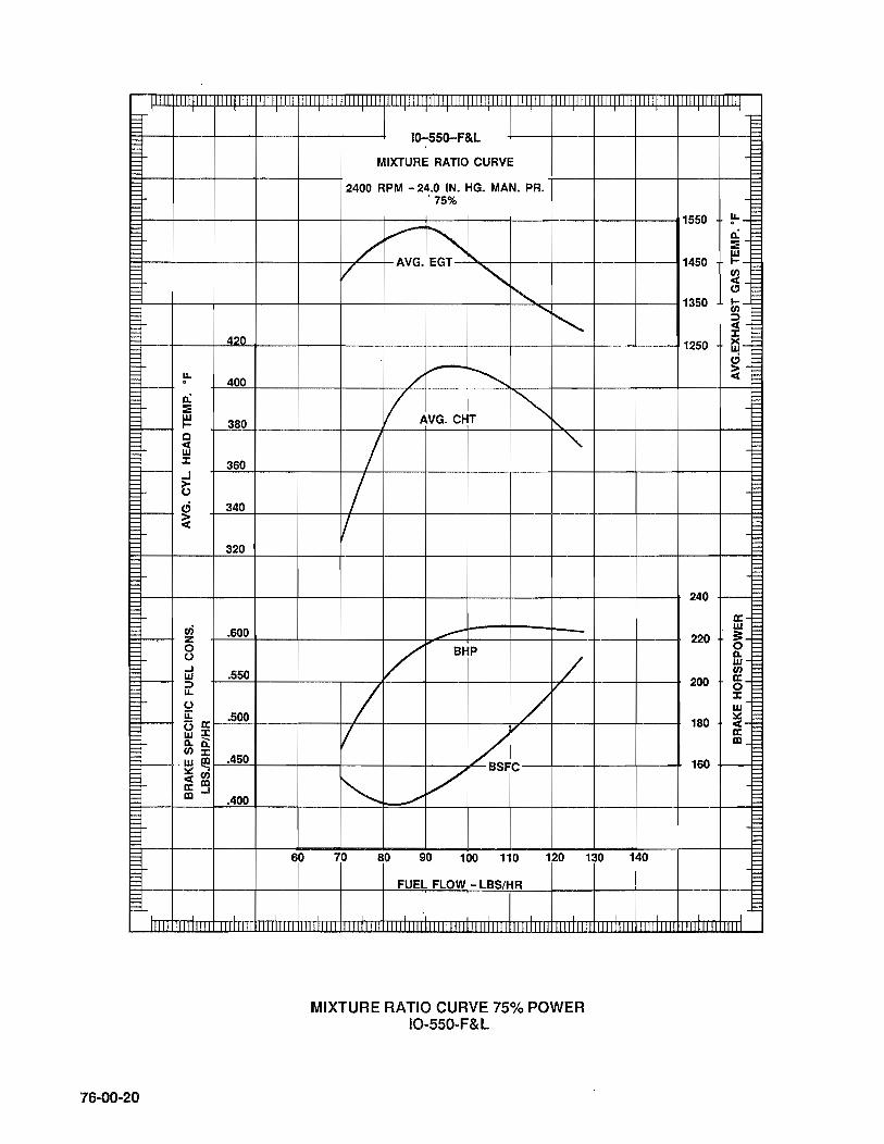
F F t= F F F ~ F F F ~ 420 E E E
~ .~ 400 t:::: 0: E E :: ~ w
I- 380 t:::: c E < E w t= :t: 360 F ~ F F ~ ci 340 E ~ E E ~ 320 t:::: E E t= t:::: E E t= ui .600 t= z
0 F 0 F ~ ..J .550 w F :::> F u. E 0 F u: .500 F (3 IX:
E w :t:
E n. 0: ~
(/') :t: .w ~ .450
I=::: lIe:(/') E <m E ~..J ~ .400 I=::: E E 1=
60 E ~ t:::: F
76-00-20
1Q-55Q-F&L
MIXTURE RATIO CURVE
2400 RPM - 24.0 IN. HG. MAN. PRo 0 75%
~ / "-V
AVG.EGT
'" '" ........ ~ / ~ ~
II AVG. CHT ~ " / '"
/ II
.--V BHP
/ 7 /v
V ~FC
V ~ -"
70 80 90 100 110 120
FUEL FLOW - LBS/HR
MIXTURE RATIO CURVE 75% POWER IO-550-F&L
m m 11111111
F E
1550 ~-§ 'E n. E :: F
I!:!-~ 1450 (/') E < E e" E
1350 E &i-:::> < :t:
1250 ~-ci ~
240
IX: w 220 ~-
n. w (/')
200 0::-0 :t: w E
180 lie: <-E IX: E mE
E 160 1=
I::: E E
130 140
I
m mm

l-
'-
IlInTfI lllllTTIn ;' m I
100% POWER FUEL PUMP PRESSURE LIMITS 10-550-D,E,F&L
NOTE: THIS DATA TO BE USED WHEN CHECKING PRESSURE AT FUEL PUIP OUTLET.
CH~RT IN~TRUdIONS I I. 1 1 I I I 1. OBTAIN ACTUAL MAXIMUM RATED RPM. 2. DETERMINE FUEL PRESSURE LIMITS FOR 100% MAXIMUM POWER BY READING
DIRECTLY ABOVE ACTUAL MAXIMUM RATED RPM POINT.
EXAMPLE: ACTUAL F.T. RPM = 2700 ± 10 FUEL PUMP PRESSURE LIMITS = 32.0 - 36.0.
NOTE: IDLE (600 ± 25 RPM) PUMP PRESSURE: 8 - 10 PSI.
38 38
en H\GH UM\T -
0.- f-36 36 I
w IX: ~--34 34 en
LOW L\M\T w IX:
.0.--32 I 32 1-:...1 H\G~ UM\~ - G
II..w -::> II.. c- -30 30 w IX: w
Ii!-:E -28 28 z
LOW UM\T - G ::>
2700 2725 2'150 I
--'--ENGINE RPM FOR 100% MAXIMUM RATED POWER
(FULL THROTTLE)
100% POWER FUEL PUMP PRESSURE LIMITS FOR IO-550-D,E,F&L
II ., c:
t::: ~ t::: t::: t::: ~ ~ t::: t::: ~ t= E E ~ t= E E ~ t= ~ t::: ~ E t::: t::: ~ t= F F ~ ~ ~ t= ~ t::: t::: t::: ~ t= E F ~ ~ t::: t::: ~ t::: t::: t::: ~ t::: E E ~ t= ~ l=-t:: f= F t= t:: t::: t::: t::: ~ f= F 1= f:: f= f= 1= t:: t::: t:
I
III IIIIII
76-00-21

r--
r--
I-I--
r---
!--
l= l= 1= l= t::: E ~ t::: E E ~ 1= f:::: f:::: 1= 1=
F'
1111
76-00-22
111111111111 InTlTIIllllllllllll1 II I J I I I I '-
FyEL FLOW LlM~TSFOR lo-55~D,E,F~L
NOTE: THIS CHART IS FOR 70°F INJECTOR FUEL TEMPERATURE. FOR EVERY 10°F INCREASE E IN INJECTOR INLET FUEL TEMPERATURE, SUBTRACT 1 LB. OF FUEL FROM THE CURVE. ~ FOR EVERY 10°F DECREASE IN INJECTOR INLET FUEL TEMPERATURE, ADD 1 LB. OF-I::: FUEL TO THE CURVE. ~
CHART INSTRUCTIONS: 1. OBTAIN ACTUAL FULL THROTTLE RPM. 2. DETERMINE REQUIRED RPM FOR 75% POWER BY READING DIRECTLY ABOVE THE
ACTUAL F.T. POINT ON THIS CHART. 3. DETERMINE FUEL FLOW LIMITS FOR F.T. AND 75% POWER BY READING DIRECTLY
ABOVE THE ACTUAL F.T. RPM POINT.· - .. --
EXAMPLES: 1. ACTUAL F.T. RPM = 2700 ± 10 FUEL FLOW LIMITS = 145 - 150 2. REQUIRED 75% RPM = 2450 ± 10 FUEL FLOW LIMITS = 100 - 115
(/) I-
-1-115 :E :::i 3:2 OJ:-1-110 ...1-. u.U) ..JIXI w..J :::J ...... !-105 u. 'if. Ie
100
2450
~ :E :::i 3:'"":'
1-155 o IX:_ ..J::r: u.-' ..JU) w lXl :::J::::L 1-150 u. 'if. 0 0
-1-145 ....
2700
1 I I I ) J I I HIGH LIMIT 75% POWER
LOW LIMIT 75% POWER I
I 2460 24rO 24~0 2490
ENGINE RPM FOR 75% POWER
.'
HIGH LIMIT F.T •
I ! LOW LIMIT F.T.
2710 2)20 2730 2740 I I I
I I I ENGINE RPM FOR 100% POWER (FULL THROTTLE)
100% POWER FUEL FLOW LIMITS FOR 10-550-D ,E,F&L
I
I
115
110
105
100
2500
155
150
145
2750
II
l= F -j:::: f:::: 1:: E l= -/:=
I f:::: !== l= _f::::
-!== !== E l= !== E E ~ j::: E= E r::: !== l= !== 1= E l= E l= j::: E E ~ j::: F F ~ 1= F 1= ~ ~ E 1= l= t::: t::: l= !== E E
F
11111

'j' lIIIII 11111 I
F ~ E E E == = == =
MAXIMUM ALLOWABLE COLLAR OIL LEAI(AGE == AT MAX. RATED POWER == = AND RPM == == b= ~
~
E = ~ == !===
10 "< ~ / / / 1/ / 1/ / ~
"< v:: / / 1/ / V ./ 8 -'<
~~/// IV / = :::: D. :::: <l
I
~// / 1/ D. 0 15-t--6
~/ V IL w == a:: == :;:) - = en_en
en D. "< L! V == w = a:: ::::: D. ~ w--4
"'< / 0 u::: a: 0
'< I-
2
0
160 1fO 2~0 220 240
I, "I" ENGINE OIL INLET TEMP • • F
1 -.l 11111 11111 lUI 1111I111 'UI !11l 11111111
MAXIMUM ALLOWABLE COLLAR OIL LEAKAGE
76-00-23
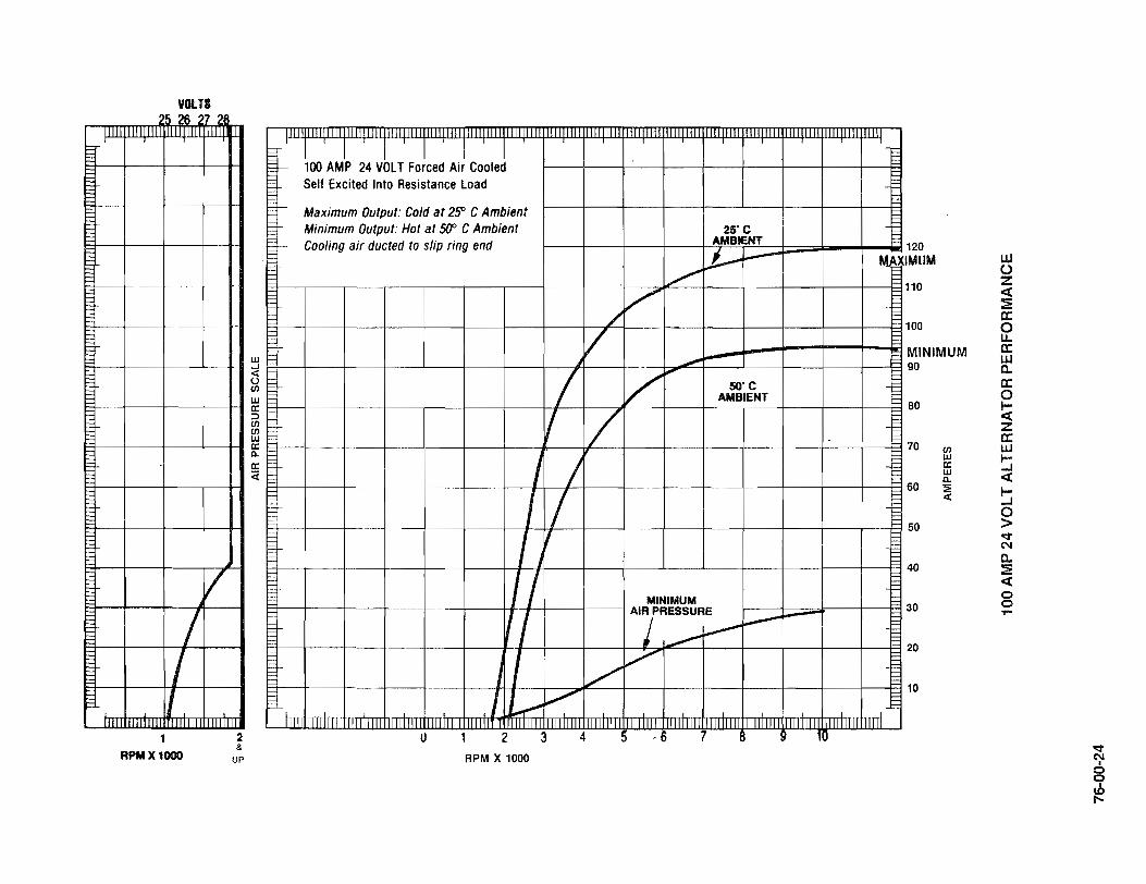
VOLTS 5262
/ /
1
RPM X 1000
7 2f
(
2 &
UP
W ...J <:: () II)
w ec ::> II) II) w ec a. ec «
III III
I I 1 I I I f- 100 AMP 24 VOLT Forced Air Cooled
Self Excited Into Resistance Load
f--- Maximum Output: Cold at 2SO C Ambient Minimum Output: Hot at 5fl' C Ambient 25"C
r- Cooling air dueted to slip ring end AMBIENT
I)---~ ./
/ /
V ~
I / """ SO"C AMBIENT
V / I' / I / // 7 MINIMUM
1/ AI7RESSURE ~
~I'-----
J I / ~
I ~ -:;;7" 11111 1111111111 IIIITIIIIi IllilmlT mill 1m 1111
U 1 2 3 4 5 ,6 7 f
RPM X 1000
-
-
MAX
-
III IIII1 10
120 MUM
110
100
MINIMUM 90
80
70
60
50
40
30
20
10
II) w ec w a. ::E «
w () Z <t :i 0:: o u. a: w c. 0:: o ~ z a: w ~ « ~ o > -:r ('II
C. :i <t o o yo-
-:r N g ~
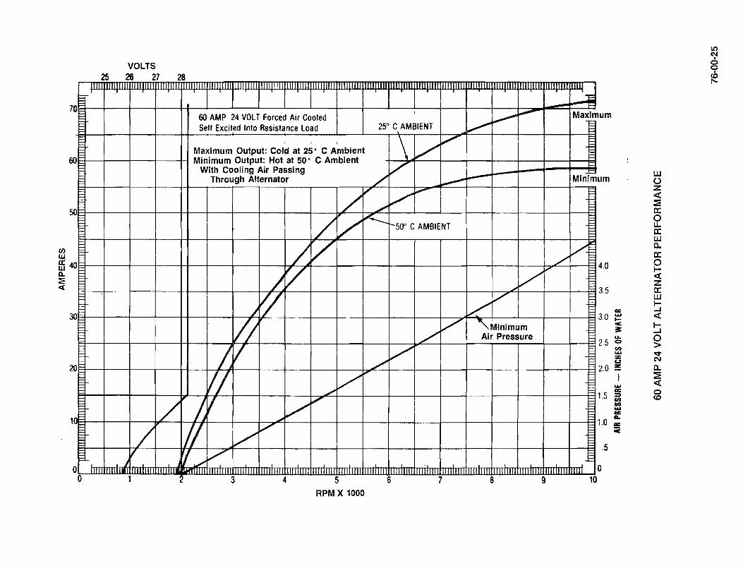
(f) w
71 )
60 I
50 I
1£40 0.. ::i:E ex:
I 30
20 0
n
o 0
VOLTS 25 26 27 28
[If III' 1111111111 mm III III IIIl1lT11111I1Hl III
60 AMP 24 VOLT Forced Air Cooled ,
Self Excited Into Resistance Load 250 C AMBIENT
: \ / ", Maximum Output: Cold at 25· C Ambient Minimum Output: Hot at 50· C Ambient
With Cooling Air Passing V Through Alternator /' ...---
/ ~ /
",..
./
/ V ~ -50" C AMBIENT
/ V J V
/ ~ k'l /"
V
! V ./ /
V/ V " ./
/ ~ f / V"
".
/ II / /'
) V '// / j -
III 'If 1& IUoff III III III 1 3 4 5 6 -7
RPM X 1000
1111 III III III 1111
~ ..".-
~
-
./
V v
J"
V V
~Mlnimum Air Pressure
III III -8 -9
III~ H
Maxim um i=
Miniml um
V~ 4.0
3.5
3.0
2.5
2.0
1.5
.0
.5 L-
o .. 10
cc ..... .... e 3r: .... CI CI':I ..... ::a:: Co)
!':
..... cc ::I CI':I co ..... III: L III: C
UJ 0 z ~ :E Il: 0 LI.. a: UJ 0-Il: 0 I-~ Z Il: UJ l-...J ~ I-...J 0 > q-N 0-:E ~ 0 to
1.1') ('.I , o o
te

76-00-26
INTENTIONALL Y
LEFT
BLANK

CHAPTER 77 ENGINE INDICATING
77-00-00 GENERAL 77-10-00 OPERATING LIMITS 77-10-01 ACCESSORIES 77-20-00 ENGINE TROUBLESHOOTING CHART
77-00-01

77-00-02
INTENTIONALL Y
LEFT
BLANK
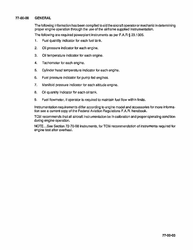
77 -00-00 GENERAL
The following information has been compiled to aid the aircraft operator or mechanic in determining proper engine operation through the use of the airframe supplied instrumentation.
The following are required powerplant instruments as per F.A.R § 23.1305.
1. Fuel quantity indicator for each fuel tank.
2. Oil pressure indicator for each engine.
3. Oil temperature indicator for each engine.
4. Tachometer for each engine.
5. Cylinder head temperature indicator for each engine.
6. Fuel pressure indicator for pump fed engines.
7. Manifold pressure indicator for each altitude engine.
8. Oil quantity indicator for each oil tank.
9. Fuel flowmeter, if operator is required to maintain fuel flow within limits.
Instrumentation requirements differ according to engine model and accessories for more information see a current copy of the Federal Aviation Regulations F.A.R. handbook.
TCM recommends that all aircraft instrumentation be in calibration and proper operating condition during engine operation.
NOTE ... See Section 72-70-08 instruments, for TCM recommendation of instruments required for engine test after overhaul.
77"()0"()3

77-00-04
INTENTIONALL Y
LEFT
BLANK

n·10-00 OPERATING LIMITS
Rated Max BHP/RPM ................................ 300 @ 2700 Idle RPM ........................................600 ± 25 Fuel Consumption at Full Throttle (lBS.lHR.) .................... 145 -150 Fuel Pump Pressure at Full Throttle (PSI) ...................... 32.0 - 36.0 Fuel Pump Pressure at Idle (PSI) . . . . . . . . . . . . . . . . . . . . . . . . . . . 8.0 - 10.0 Metered Fuel Pressure at Full Throttle (PSI) ..................... 18.5 -19.5 Metered Fuel Pressure at Cruise (PSI) . . . . . . . . . . . . . . . . . . . . . . . .11.2 - 12.6 Engine Intake Air Temperature . . . . . . . . . . . . . . . . . . . . . . . . . . . . . Ambient Engine Intake Air Pressure . . . . . . . . . . . . . . . . . . . . . . . . . . . . . . . Ambient Rated Manifold Pressure (at Sea Level) ...................... Full Throttle Fuel Grade (Octane) Minimum .......................... 100 or 100ll
Refer to chapter & Section Oil Specification . • . . . . . . . . . . . . . . . . . . . . . . . 79-10-00 for Spec. MHS 24 D Above 40'F ...•................................... SAE 50 Below 40'F ................................. SAE 30 or 10W-30 10-550-D Oil Sump Capacity (U.S. Quarts) .. . . . . . . . . . . . . . . . . . . . . . . . . . . . . . 12
Usable Oil- Quarts 20' Nose Up ............................ 7.0 Usable Oil - Quarts 15' Nose Down .......................... 7.0
10-550-E Oil Sump Capacity (U.S. Quarts) . . . . . . . . . . . . . . . . . . . . . . . . . . . . . . . 12
Usable Oil - Quarts 15' Nose Up . . . . . . . . . . . . . . . . . . . . . . . . . . . . 8.0 Usable Oil - Quarts 5' Nose Down . . . . . . . . . . . . . . . . . . . . . . . . . . . 8.0
10-550-F Oil Sump Capacity (U.S. Quarts) ............................... 12
Usable Oil - Quarts 20' Nose Up . . . . . . . . . . . . . . . . . . . . . . . . . . . . 7.0 Usable Oil - Quarts 15' Nose Down .......................... 6.0
10-550-l Oil Sump Capacity (U.S. Quarts) . . . . . . . . . . . . . . . . . . . . . . . . . . . . . . . 10
Usable Oil- Quarts 20' Nose Up ............................ 7.8 Usable Oil - Quarts 15° Nose Down .......................... 6.7
Max. Oil Consumption (lB.IBHP.lHR. Max. At Rated Power At RPM)
ALL MODELS: .006 LBS. X % Power 100
Oil Temperature Limits:
Minimum for Take-Off ................................. 75°F Maximum Allowable ................................. .240°F Recommended Cruising ..... . . . . . . . . . . . . . . . . . . . . . . . . . . .170°F
Oil Pressure (PSI)
Idle, Minimum ...................................... 10 Normal Operation Above Idle ........................... 30 to 60
Ignition Timing (Compression Stroke, Breaker Opens)
Right Magneto, Degrees BTC ........................... .220 ± l' Left Magneto, Degrees BTC . . . . . . . . . . . . . . . . . . . . . . . . . . . . .220 ± 1"
Magneto Spread (at 2100 RPM)
Maximum . . . . . . . . . . . . . . . . . . . . . . . . . . . . . . . . . . . . . . 50 RPM
Cylinder Head Temperature (with bayonet thermocouple)
Maximum . • . . . . . . . . . . . . . . . . . . . . . . . . . . . . . . . . . . . • . .460°F Recommended Cruise .. . . . . . . . . . . . . . • . . . . . . . . . . . . 360' to 420·F
n-10-01

77·10-00 Operating Limits (continued)
Crankcase Pressure
Maximum H20 ..................................... .4.0"
77·10-01 Accessories
Magnetos (10-550-0 & E) . . . . . . . . . . . . . . . . . . . . . . . . . TCM (S1200 Series) Slick Electro (6210)
Magnetos (10-550-F & L) ..................... TCM (S1200 Series) Optional Ignition Harnesses
(10-550-0 & E) . . . . . . . . . . . . . . . . . . . . . . . . . . . . . . . . . TCM (5MM) Slick Electro (5MM Sheilded)
(10-550-F & L) ............................ TCM (5MM) Optional
Spark Plugs . . . . . . . . . . . . . . . . 18MM X .750-20 Thd. Connection (FAA Approved) Champion ........................ RHB32E (TCM Part No., 634675)
Oil Cooler
10-550-0, E & F ............................... TCM (Modine)
10-550-L ................................ Customer Supplied Customer Supplied
Alternator ......................... .. Prestolite 24V 70 AMP (Optional) Starter . . . . . . . . . . . . . . . . . . . . . . . . . . . . . . . . . . . . . . . TCM (24 Volt) Fuel Injection System . . . . . . . . . . . . . . . . . . . . . . . . . . . . . . . . . . . . TCM Quick Start Primer
10-550-E ........................................ TCM
ACCESSORIES DRIVE RATIOS TO CRANKSHAFT(Viewing Drive)
Direction Drive Ratio Accessory Of to
Rotation * Crankshaft
Tachometer Optional .5:1
Magneto CCW 1.5:1
Starter CCW 32:1
Alternator (Belt Dr.) CCW 2:1
**Propeller Gov. CW 1:1
Fuel Pump (Injection) CW 1 :1
Accessory Drives (2) CW 1.5:1
* "CW' - Clockwise and "CCW' - Counterclockwise
**This drive is a modified AN020010 and is supplied with cover plate only.
77·10-02

77-20-00 ENGINE TROUBLESHOOTING
This troubleshooting chart is provided as a guide. Review all probable causes given, check other listings of troubles with similar symptoms. Items are presented in sequence of the approximate ease of checking, not necessarily in order of probability.
TROUBLE PROBABLE CAUSE CORRECTION
Fuel tank empty. Fill with correct grade fuel.
Improper starting procedure. Refer to Pilot's Checklist for start-ing procedures and check for per-formance of each item.
Cylinder overprimed. Engine Place mixture levers in IDLE CUT-flooded. OFF position. Open throttle wide.
Turn engine over several revolu-tions to clear cylinders.
Engine Will Not Start Induction system leak. Tighten or replace loose or
damaged hose connection.
Excessive starter slippage. Replace starter adapter.
Fuel system malfunction. Isolate cause and correct. (See Troubleshooting the Fuel Injection System.)
Ignition system malfunction. Isolate cause and correct. (See Troubleshooting the Ignition Sys-tem.)
Manifold valve vent obstruction. Repair or replace manifold valve.
Propeller levers set in high pitch Use low pitch (INCREASE RPM) (DECREASE RPM). pOSition for all gound operations.
Engine Will Not Run At Idling Fuel injection system improperly See Troubleshooting the Fuel In-Speed adjusted. jection System.
Air leak in intake manifold. Tighten loose connection or replace damaged part.
Fuel injection system improperly See Troubleshooting the Fuel In-adjusted. jection System.
Mixture levers set for improper Use FULL RICH position for all mixture. ground operation, except high al-
titude airports.
Rough Idling Fouled spark plugs. Remove and clean. Adjust gaps.
Hydraulic tappets fouled. Remove and clean tappets. In-spect and clean oil filter at more frequent intervals.
Burned or warped exhaust valves, Repair cylinder. worn seat, scored.
77-20-01
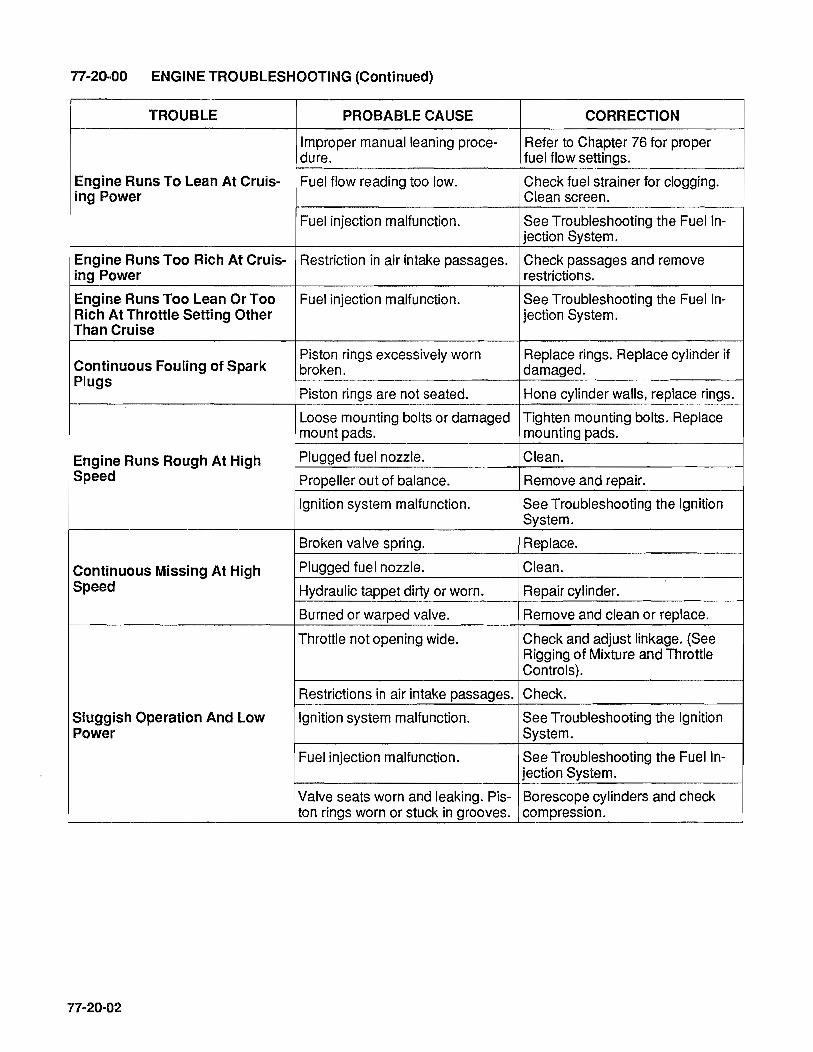
77-20-00 ENGINE TROUBLESHOOTING (Continued)
TROUBLE PROBABLE CAUSE CORRECTION
Improper manual leaning proce- Refer to Chapter 76 for proper dure. fuel flow settings.
Engine Runs To Lean At Cruis- Fuel flow reading too low. Check fuel strainer for clogging. ing Power Clean screen.
Fuel injection malfunction. See Troubleshooting the Fuel In-jection System.
Engine Runs Too Rich At Cruis- Restriction in air intake passages. Check passages and remove ing Power restrictions.
Engine Runs Too Lean Or Too Fuel injection malfunction. See Troubleshooting the Fuel In-Rich At Throttle Setting Other jection System. Than Cruise
Continuous Fouling of Spark Piston rings excessively worn Replace rings. Replace cylinder if broken. damaged.
Plugs Piston rings are not seated. Hone cylinder walls, replace rings.
Loose mounting bolts or damaged Tighten mounting bolts. Replace mount pads. mounting pads.
Engine Runs Rough At High Plugged fuel nozzle. Clean. Speed Propeller out of balance. Remove and repair.
Ignition system malfunction. See Troubleshooting the Ignition System.
Broken valve spring. Replace.
Continuous Missing At High Plugged fuel nozzle. Clean. Speed Hydraulic tappet dirty or worn. Repair cylinder.
Burned or warped valve. Remove and clean or replace.
Throttle not opening wide. Check and adjust linkage. (See Rigging of Mixture and Throttle Controls).
Restrictions in air intake passages. Check.
Sluggish Operation And Low Ignition system malfunction. See Troubleshooting the Ignition Power System.
Fuel injection malfunction. See Troubleshooting the Fuel In-jection System.
Valve seats worn and leaking. Pis- Borescope cylinders and check ton rings worn or stuck in grooves. compression.
77-20-02

77-20-00 ENGINE TROUBLESHOOTING (Continued)
TROUBLE PROBABLE CAUSE CORRECTION
Low octane fuel. Drain tanks and replace with Cor-rect Grade of Fuel.
Lean fuel/air mixture due to im- See "CORRECTION" under "En-proper manual leaning procedure. gine runs too lean at cruising
power."
Cylinder baffles loose or bent. Check and correct.
High Cylinder Head Tempera- Dirt between cylinder fins. Clean thoroughly. ture
Excessive carbon deposits in Check ignition and fuel injection cylinder head and on pistons. system.
Magnetos out of time. No appreci- Re-time, internally and externally. able drop detected during pre-flight check.
Magneto distributor block con- Disassemble and repair as re-tamination. quired or replace magneto.
High Cylinder Head Tempera- Exhaust system gas leakage. Locate and correct.
ture Exhaust valve leaking. Repair cylinder.
At front of engine; damaged Replace. crankshaft oil seal.
Oil Leaks Around propeller mounting flange: Replace. damaged hub O-ring seal.
Around plugs, fittings and gaskets Tighten or replace. due to looseness or damage.
Piston rings excessively worn. Repair cylinder.
Low Compression Valve faces and seat worn. Repair cylinder.
Excessively worn cylinder walls. Replace cylinder & Piston rings.
Slow Engine Acceleration On A Mixture too rich Momentarily pull mixture control back until engine acceleration
Hot Day picks up, then set proper mixture.
Rough Idle At Airfields With Mixture too rich. Pull mixture control back to where Ground Elevation of 3500 Feet the engine operates the Or Higher. smoothest at IDLE RPM.
Slow Engine Acceleration At Mixture too rich. Adjust mixture per Chapter 76. Airfields With A Ground Eleva-tion of 3500 Feet Or Higher
Engine Will Not Stop At Idle Cut- Fuel manifold valve not seating Repair or replace manifold valve. Off tightly.
Fuel Manifold valve sticking Repair or replace manifold valve.
High Engine Idle Pressure Im- closed.
possible To Obtain Fuel manifold valve vent obstruc- Repair or replace manifold valve. tion.
77-20-03

77-20-00 ENGINE TROUBLESHOOTING (Continued)
TROUBLE PROBABLE CAUSE CORRECTION
Erratic Engine Operation Fuel manifold valve sticking, or Repair or replace manifold valve. not free.
Climbing To Altitudes Above Fuel vaporization. Operate fuel boost pump accord-
12,000 Feet, Engine Quits When ing to aircraft manufacturer's in-structions. See fuel flow per Power Reduced. Chapter 76.
Restricted flow to fuel metering Check mixture control for full valve. travel. Check for restrictions in
fuel filters and lines, adjust control and clean filter. Replace damaged parts.
Fuel control lever interference. Check operation of throttle control
Low Fuel Pressure and for possible contact with cool-ing shroud. Adjust as required to obtain correct operation.
Incorrect fuel injector pump adjust- Check and adjust using ap-ment and operation. propriate equipment. Replace mal-
functioning pumps.
Malfunctioning fuel injector pump Replace pump. relief valve.
Restricted flow beyond fuel con- Check for restriicted fuel nozzles trol assembly. or fuel manifold valve. Clean or
replace nozzles. Replace mal-functioning fuel manifold valve.
High Fuel Pressure Malfunctioning relief valve opera- Replace fuel injector pump. tion in fuel injector.
Restricted re-circulation passage Replace pump. in fuel injector pump.
Vapor in fuel system, excessive Normally, operating the auxiliary fuel temperature. pump will clear system. Operate
auxiliary pump and purge system.
Fuel gauge line leak or air in Drain gauge line and tighten con-
Fluctuating Fuel Pressure gauge line. nections.
Restrictions in vapor separator Check for restrictions in ejector jet vent. of vapor separator cover. Clean
jet with solvent (only). Do Not Use Wire as Probe. Replace mal-fucntioning parts.
Insufficient oil in oil sump oil dilu- Add oil, or oil change oil to proper tion or using improper grade oil for viscosity.
Low Oil Pressure On Engine prevailing ambient temperature.
High oil temperature. Malfunctioning oil temperature Gauge control valve in oil cooler; oil cooler restriction. Replace valve or clean oil cooler.
n-20-04
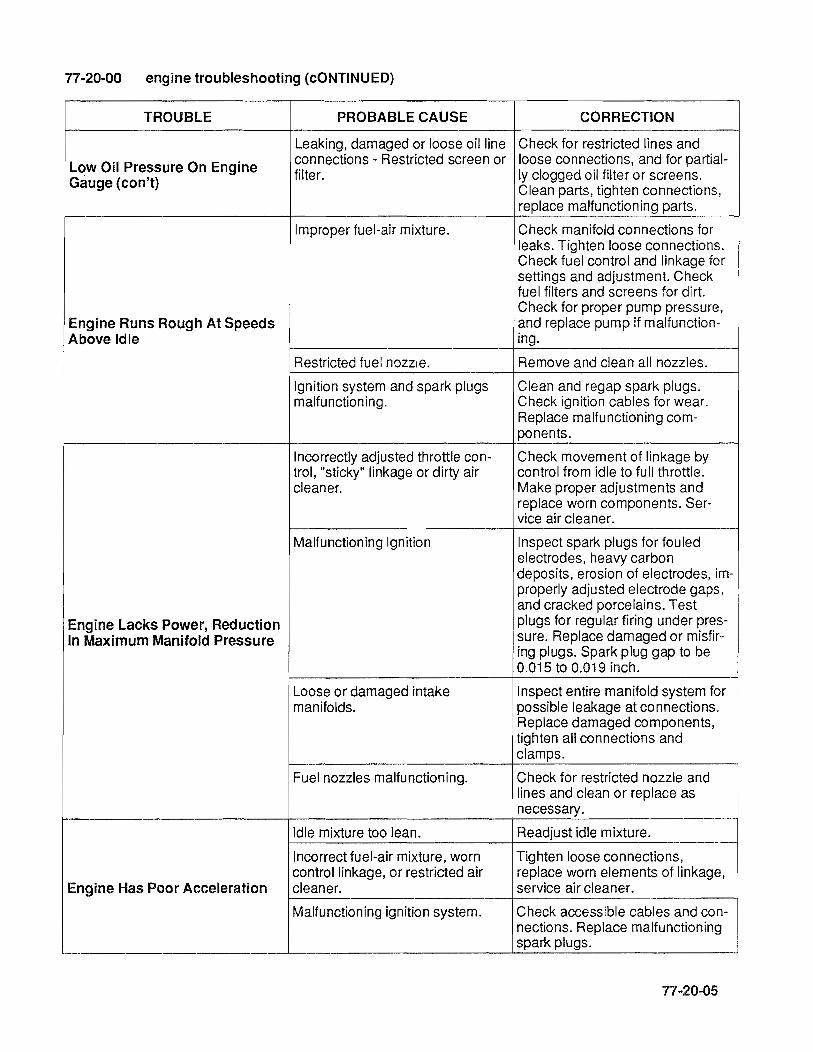
77·20-00 engine troubleshooting (cONTINUED)
TROUBLE PROBABLE CAUSE CORRECTION
Leaking, damaged or loose oil line Check for restricted lines and
Low Oil Pressure On Engine connections - Restricted screen or loose connections, and for partial-
Gauge (con't) filter. Iy clogged oil filter or screens. Clean parts, tighten connections, replace malfunctioning parts.
Improper fuel-air mixture. Check manifold connections for leaks. Tighten loose connections. Check fuel control and linkage for settings and adjustment. Check fuel filters and screens for dirt. Check for proper pump pressure,
Engine Runs Rough At Speeds and replace pump if malfunction-Above Idle ing.
Restricted fuel nozzle. Remove and clean all nozzles.
Ignition system and spark plugs Clean and regap spark plugs. malfunctioning. Check ignition cables for wear.
Replace malfunctioning com-ponents.
Incorrectly adjusted throttle con- Check movement of linkage by trol, "sticky" linkage or dirty air control from idle to full throttle. cleaner. Make proper adjustments and
replace worn components. Ser-vice air cleaner.
Malfunctioning Ignition Inspect spark plugs for fouled electrodes, heavy carbon deposits, erosion of electrodes, im-properly adjusted electrode gaps, and cracked porcelains. Test
Engine Lacks Power, Reduction plugs for regular firing under pres-
In Maximum Manifold Pressure sure. Replace damaged or misfir-ing plugs. Spark plug gap to be 0.015 to 0.019 inch.
Loose or damaged intake Inspect entire manifold system for manifolds. possible leakage at connections.
Replace damaged components, tighten all connections and clamps.
Fuel nozzles malfunctioning. Check for restricted nozzle and lines and clean or replace as necessary.
Idle mixture too lean. Readjust idle mixture.
Incorrect fuel-air mixture, worn Tighten loose connections, control linkage, or restricted air replace worn elements of linkage,
Engine Has Poor Acceleration cleaner. service air cleaner.
Malfunctioning ignition system. Check accessible cables and con-nections. Replace malfunctioning spark plugs.
77-20-05

77-20-06
INTENTIONALLY LEFT
BLANK
CHAPTER 78 EXHAUST
78-00-00 GENERAL
78-00-01

78-00-02
INTENTIONALLY
LEFT
BLANK

78-00-00 GENERAL
Exhaust systems for the 10-550-0, E, F & L, are supplied by the aircraft manufacturer.
For exhaust system overhaul maintenance and troubleshooting, refer to the airframe manufacturer's instructions.
78-00-03

78-00-04
INTENTIONALL Y
LEFT
BLANK

CHAPTER 79 OIL
79-00-00 GENERAL
79-10-00. APPROVED OIL PRODUCTS
79-20-00 OIL SYSTEM TROUBLESHOOTING CHART

79-00-02
INTENTIONALL Y
LEFT
BLANK

79-00-00 GENERAL
The marketers of the aviation lubricating oils listed on page 79-10-01 have supplied data to Teledyne Continental Motors indicating their products conform to all requirements of TCM Specification MHS-25 and MHS-24 Lubricating Oil, Ashless Dispersant.
In listing the product names, TCM makes no claim or verification of marketer's statements orclaims. Listing is made in alphabetical order and is provided only for the convenience of the user.
79-00-03

79-00-04
INTENTIONALLY
LEFT
BLANK

79·10-00 APPROVED OIL PRODUCTS
Supplier
MHS-25
Mobil Oil Company
MHS - 24D
BP Oil Corporation
Castrol Limited (Australia)
Chevron U.S.A., Inc.
Continental Oil
Delta Petroleum Company
Exxon Company, U.S.A., Exxon Aviation Oil EE
Gulf Oil Company
Mobil Oil Company
Mobil Oil Company
Pennzoil Company
Phillips Petroleum Company
Phillips Petroleum Company
Quaker State Oil & Refining Co. Turbo Resources Limited (Canada)
Shell Canada Limited
Shell Oil Company
Shell Australia
Sinclair Oil Company
Texaco, Inc.
Union Oil Company of California
"'NOTE ... This does not include XlC Aviation Oil.
Mobil AV1
BPAero Oil Castrolaero AD Oil
Chevron Aero Oil
Conco Aero S
Delta A voil Oil
Gulfpride Aviation AD
Mobil Aero Oil
Brand
Mobil Aero Super Oil SAE 20 W-50
Pennzoil Aircraft Engine Oil
Phillips 66 Aviation Oil, Type A
*XlC Aviation Multiviscosity Oil
SAE 20W-50, SAE 20W-60
Quaker State AD Aviation Engine 011 Red Ram 20W-50 Aviation Motor Oil Aeroshell Oil W. Aeroshell Oil W 15W-50
Aeroshell Oil W. Aeroshell Oil W 15W-50
Aeroshell Oil W. Aeroshell Oil W 15W-50 (with additive)
Sinclair Avoil
Texaco Aircraft Engine Oil-Premium AD
Union Aircraft Engine Oil HD
NOTE ... The operator using an oil service is reminded that an oil analysis does not reveal all abnormal engine conditions. It should not be used as a replacement or substitute for routine maintenance and inspection procedures recommended in the Operator's Manual, Service Bulletins, or other directives. For further information, see TCM Service Bulletin M86-8R1 or current revisions as applicable.
79-10-01

79-10-02
INTENTIONALL Y
LEFT
BLANK
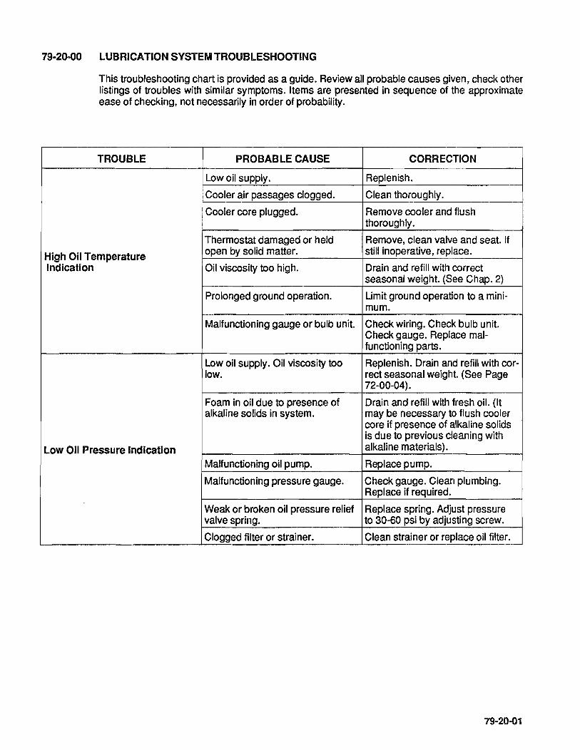
79-20-00 LUBRICATION SYSTEM TROUBLESHOOTING
This troubleshooting chart is provided as a guide. Review all probable causes given, check other listings of troubles with similar symptoms. Items are presented in sequence of the approximate ease of checking, not necessarily in order of probability.
TROUBLE PROBABLE CAUSE CORRECTION
Low oil supply. Replenish.
Cooler air passages clogged. Clean thoroughly.
Cooler core plugged. Remove cooler and flush thoroughly.
Thermostat damaged or held Remove, clean valve and seat. If
High Oil Temperature open by solid matter. still inoperative, replace.
Indication Oil viscosity too high. Drain and refill with correct seasonal weight. (See Chap. 2)
Prolonged ground operation. Limit ground operation to a mini-mum.
Malfunctioning gauge or bulb unit. Check wiring. Check bulb unit. Check gauge. Replace mal-functioning parts.
Low oil supply. Oil viscosity too Replenish. Drain and refill with cor-low. rect seasonal weight. (See Page
72-00-04).
Foam in oil due to presence of Drain and refill with fresh oil. (It alkaline solids in system. may be necessary to flush cooler
core if presence of alkaline solids is due to previous cleaning with
Low Oil Pressure Indication alkaline materials).
Malfunctioning oil pump. Replace pump.
Malfunctioning pressure gauge. Check gauge. Clean plumbing. Replace if required.
Weak or broken oil pressure relief Replace spring. Adjust pressure valve spring. to 30-60 psi by adjusting screw.
Clogged filter or strainer. Clean strainer or replace oil filter.
79-20-01

79-20-02
INTENTIONALL Y
LEFT
BLANK
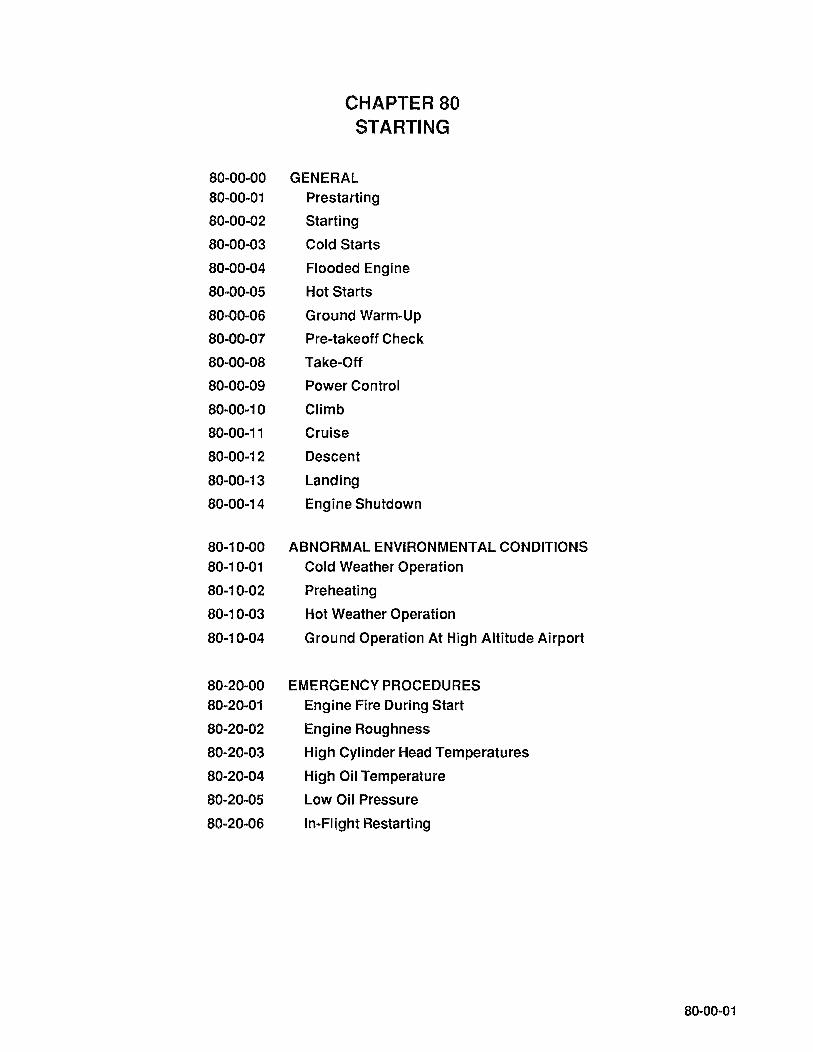
80-00-00
80-00-01
80-00-02
80-00-03
80-00-04
80-00-05
80-00-06
80-00-07
80-00-08
80-00-09
80-00-10
80-00-11
80-00-12
80-00-13
80-00-14
80-10-00
80-10-01
80-10-02
80-10-03
80-10-04
80-20-00 80-20-01
80-20-02
80-20-03
80-20-04
80-20-05
80-20-06
CHAPTER 80 STARTING
GENERAL Prestarting
Starting
Cold Starts
Flooded Engine
Hot Starts
Ground Warm-Up
Pre-takeoff Check
Take-Off
Power Control
Climb
Cruise
Descent
Landing
Engine Shutdown
ABNORMAL ENVIRONMENTAL CONDITIONS Cold Weather Operation
Preheating
Hot Weather Operation
Ground Operation At High Altitude Airport
EMERGENCY PROCEDURES Engine Fire During Start
Engine Roughness
High Cylinder Head Temperatures
High Oil Temperature
Low Oil Pressure
In-Flight Restarting
80-00-01

80-00-02
INTENTIONALLY
LEFT
BLANK
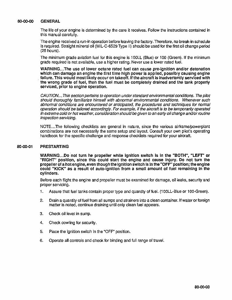
80-00-00 GENERAL
80-00-01
The life of your engine is determined by the care it receives. Follow the instructions contained in this manual carefully.
The engine received a run-in operation before leaving the factory. Therefore, no break-in schedule is required. Straight mineral oil (MIL-C-6529 Type II) should be used for the first oil change period (25 hours).
The minimum grade aviation fuel for this engine is 100LL (Blue) or 100 (Green). If the minimum grade required is not.available, use a higher rating. Never use a lower rated fuel.
WARNING ... The use of lower octane rated fuel can cause pre-ignition and/or detonation which can damage an engine the first time high power is applied, possibly causing engine
, failure. This would most likely occur on takeoff. If the aircraft is inadvertently serviced with the wrong grade of fuel, then the fuel must be completely drained and the tank properly serviced, prior to engine operation.
CAUTION ... This section pertains to operation under standard environmental conditions. The pilot should thoroughly familiarize himself with abnormal environmental conditions. Whenever such abnormal conditions are encountered or anticipated, the procedures and techniques for normal operation should be tailored accordingly. For example, if the aircraft is to be temporarily operated in extreme cold or hot weather, consideration should be given to an early oil change and/or routine inspection seNicing.
NOTE ... The following checklists are general in nature, since the various airframe/powerplant combinations are not necessarily the same setup and layout. Consult your own pilot's operating handbook for the specific challenge and response checklists required for your aircraft.
PRESTARTING
WARNING ... Do not turn he propeller while ignition switch Is In the "BOTH", "LEFT" or "RIGHT" pOSition, since this could start the engine and cause Injury. Do not turn the propeller of a hot engine, even though the ignition switch is in the "OFF" position; the engine could "KICK" as a result of auto-ignition from a small amount of fuel remaining In the cylinders.
Before each flight the engine and propeller must be examined for damage, oil leaks, security and proper servicing.
1. Assure that fuel tanks contain proper type and quantity of fuel. (1 OOLL-Blue or 100-Green).
2. Drain a quantity of fuel from all sumps and strainers into a clean container. If water or foreign matter is noted. continue draining until only clean fuel appears.
3. Check oil level in sump.
4. Check cowling for security.
5. Place the ignition switch in the "OFF" position.
6. Operate all controls and check for binding and full range of travel.
8()"()0..()3
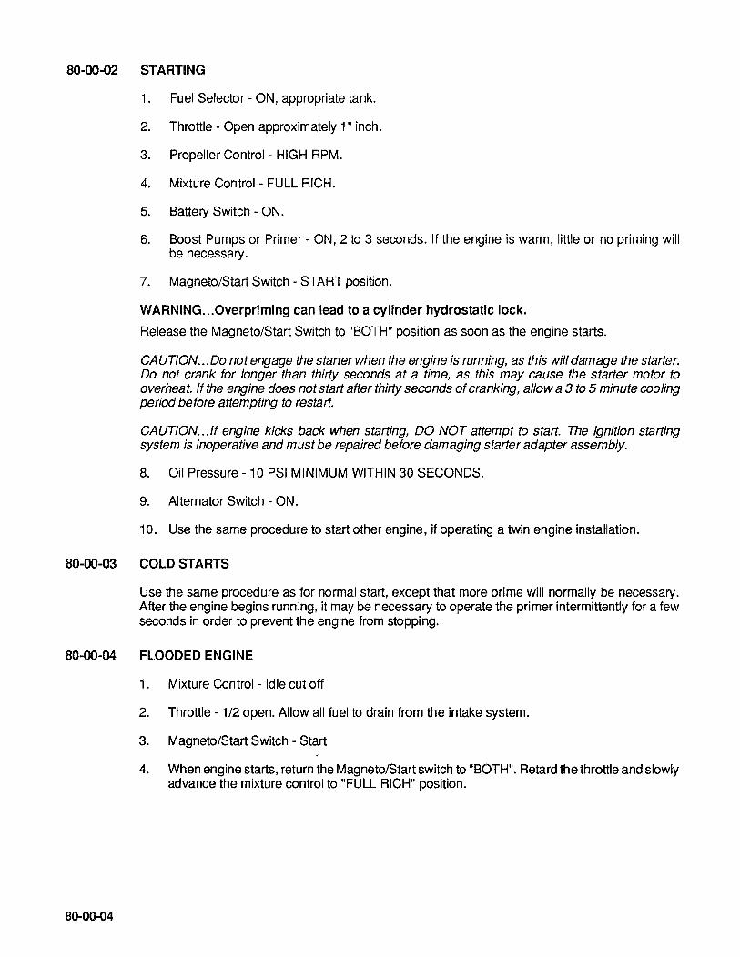
80-00-02 STARTING
1. Fuel Selector - ON, appropriate tank.
2. Throttle - Open approximately 1" inch.
3. Propeller Control - HIGH RPM.
4. Mixture Control- FULL RICH.
5. Battery Switch - ON.
6. Boost Pumps or Primer - ON, 2 to 3 seconds. If the engine is warm, little or no priming will be necessary.
7. Magneto/Start Switch - START position.
WARNING ... Overpriming can lead to a cylinder hydrostatic lock.
Release the Magneto/Start Switch to "BOTH" position as soon as the engine starts.
CAUTION ... 00 not engage the starter when the engine is running, as this will damage the starter. Do not crank for longer than thirty seconds at a time, as this may cause the starter motor to overheat. ff the engine does not start after thirty seconds of cranking, allow a 3 to 5 minute cooling period before attempting to restart.
CAUTION ... ff engine kicks back when starting, DO NOT attempt to start. The ignition starting system is inoperative and must be repaired before damaging starter adapter assembly.
8. Oil Pressure - 10 PSI MINIMUM WITHIN 30 SECONDS.
9. Alternator Switch - ON.
10. Use the same procedure to start other engine, if operating a twin engine installation.
80-00-03 COLD STARTS
Use the same procedure as for normal start, except that more prime will normally be necessary. After the engine begins running, it may be necessary to operate the primer intermittently for a few seconds in order to prevent the engine from stopping.
80-00-04 FLOODED ENGINE
80-00-04
1. Mixture Control - Idle cut off
2. Throttle - 1/2 open. Allow all fuel to drain from the intake system.
3. Magneto/Start Switch - Start
4. When engine starts, return the Magneto/Start switch to "BOTH". Retard the throttle and slowly advance the mixture control to "FULL RICH" position.

80-00-05 HOT STARTS
Use the same procedure as for normal start, except have mixture control full lean, throttle full open, and boost pump on high for approximately 15 to 20 seconds. See Hot Weather Operation (80-10-03)
80-00-06 GROUND WARM-UP
Teledyne ContinentaIIO-550-D,E,F & L engines are aircooled and are dependent on the forward speed of the aircraft for cooling. To prevent overheating, it is important that the following rules be observed.
1. Head the aircraft into the wind.
2. Operate the engine on the ground with the propeller in "Full Increase" RPM position.
3. Avoid prolonged idling at low RPM. Fouled spark plugs can result from this practice.
4. Leave mixture in "Full Rich". (See "Ground Operation at High Altitude Airport", 80-10-04 for exceptions).
5. Warm-up - 900-1000 RPM.
80-00-07 PRE·TAKEOFF CHECK
1. Maintain engine speed at approximately 900 to 1000 RPM for at least one minute in warm weather, and as required during cold weather, to prevent cavitation in the oil pump and to ensure adequate lubrication.
2. Advance throttle slowly until tachometer indicates an engine speed of approximately 1200 RPM. Allow additional warm-up time at this speed depending on ambient temperature. This time may be used for taxiing to takeoff position. The minimum allowable oil temperature for run-up is 75°F.
CAUTION ... 00 not operate the engine at run-up speed unless oil temperature is 75°F. minimum and oil pressure is within specified limits of 30-60 PSI.
3. Perform all ground operations with cowling flaps, (if installed), full open, with mixture control in "FULL RICH" pOSition, dependent on field elevation and propeller control set for maximum RPM (except for brief testing of propeller governor).
4. Restrict ground operations to the time necessary for warm-up and testing.
5. Increase engine speed 1700 RPM only long enough to perform the following checks:
A. Magnetos: With both magnetos "ON", position the right magneto switch "OFF" and note engine RPM; now back to both magnetos "ON" to clear the spark plugs. Then position the left magneto switch "OFF" and note engine RPM. Now return switch to both magnetos "ON". The difference between the two magneto's operated individually should not differ more than 50 RPM with a maximum drop for either magneto of 150 RPM. Observe engine for excessive roughness during this check.
If no drop in RPM is observed when operating on either magneto alone, switch circuit should be inspected.
8G-OO-o5
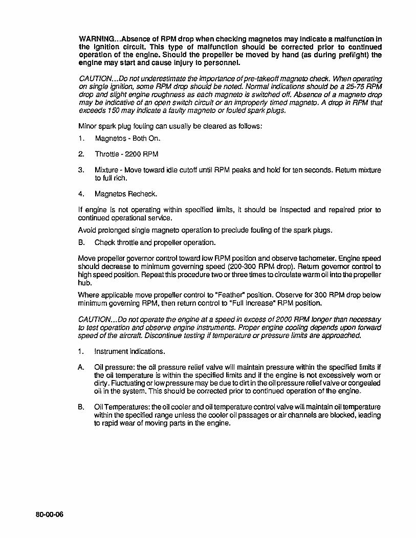
80-00-06
WARNING ... Absence of RPM drop when checking magnetos may indicate a malfunction in the ignition circuit. This type of malfunction should be corrected prior to continued operation of the engine. Should the propeller be moved by hand (as during preflight) the engine may start and cause Injury to personnel.
CAUTION ... Do not underestimate the importance of pre-takeoff magneto check. When operating on single ignition, some RPM drop should be noted. Normal indications should be a 25-75 RPM drop and slight engine roughness as each magneto is switched off. Absence of a magneto drop may be indicative of an open switch circuit or an improperly timed magneto. A drop in RPM that exceeds 150 may indicate a faulty magneto or fouled spark plugs.
Minor spark plug fouling can usually be cleared as follows:
1. Magnetos - Both On.
2. Throttle - 2200 RPM
3. Mixture - Move toward idle cutoff until RPM peaks and hold for ten seconds. Return mixture to full rich.
4. Magnetos Recheck.
If engine is not operating within specified limits, it should be inspected and repaired prior to continued operational service.
Avoid prolonged single magneto operation to preclude fouling of the spark plugs.
B. Check throttle and propeller operation.
Move propeller governor control toward low RPM position and observe tachometer. Engine speed should decrease to minimum governing speed (200-300 RPM drop). Return governor control to high speed poSition. Repeat this procedure two or three times to circulate warm oil into the propeller hub.
Where applicable move propeller control to "Feather" position. Observe for 300 RPM drop below minimum governing RPM, then return control to "Full Increase" RPM poSition.
CAUTION ... 00 not operate the engine at a speed in excess of 2000 RPM longer than necessary to test operation and observe engine instruments. Proper engine cooling depends upon forward speed of the aircraft. Discontinue testing if temperature or pressure limits are approached.
1. Instrument indications.
A. Oil pressure: the oil pressure relief valve will maintain pressure within the specified limits if the oil temperature is within the specified "mits and if the engine is not excessively worn or dirty. Fluctuating or low pressu re may be due to dirt in the oil pressure relief valve or congealed oil in the system. This should be corrected prior to continued operation of the engine.
B. Oil Temperatures: the oil cooler and oil temperature control valve will maintain oil temperature within the specified range unless the cooler oil passages or air channels are blocked, leading to rapid wear of moving parts in the engine.

C. Cylinder Head Temperature: any temperature in excess of the specified limit may cause cylinder or piston damage. Proper cooling of cylinders depends on cylinder baffels being properly positioned on the cylinder heads and barrels, and other joints in the pressure compartment being tight to force air between the cylinder fins. Proper cooling also depends on operating practices. Fuel and air mixture ratio will affect cylinder temperature. Excessively lean mixture causes overheating even when the cooling system is in good condition. High power and low air speed, or any slow speed flight operation, may cause overheating by reducing the cooling air flow. The engine depends on the ram air flow developed by the forward motion of the aircraft for proper cooling.
D. Battery Charging: the ammeter should indicate a negative charging rate while the engine is being started. The ammeter reading should return to the positive side as soon as the engine starts and RPM increases. A low charging rate is normal after the initial recharging of battery. A zero reading or negative reading with electrical load may indicate a malfunction in the alternator or regulator system.
80-00-08 TAKEOFF
1. Position mixture to "FULL RICH". Where installed cowl flaps should be pOSitioned as specified by the aircraft manufacturer.
2. Position fuel boost pump switch as instructed by the aircraft manufacturer.
3. Use full throttle to obtain rated power for takeoff. During takeoff, observe manifold pressure, RPM, fuel flow, engine temperature and oil pressure. All should be within normal limits.
80-00-09 POWER CONTROL
When increasing power, first increase the RPM with the propeller control and then increase manifold pressure with throttle. When decreasing power, throttle back to desired manifold pressure and then adjust to the desired RPM. Readjust manifold pressure after final RPM setting.
80-00-10 CLIMB
1. Recommended power for climb is 78%.
2. Climb at 78% power and above must be accomplished with a "FULL RICH" mixture setting and cowl flaps, if provided, set to maintain desired temperature.
3. During climb (immediately after takeoff), observe manifold pressure, RPM, fuel flow, engine temperature and oil pressure. All should be within normal limits.
NOTE ... Generally, when the aircraft has been configured for climbout, engine power should be reduced. Recommended power for normal climb is 78% with a "FULL RICH' mixture setting. If power settings of greater than 78% are required, particular attention should be given to cylinder head, E.G.T., and oil temperatures, and mixture must be "FULL RICH".
WARNING ... At power settings above 80%, do not use the E.G.T. gauge as an aid to adjust mixture. Mixture "FULL RICH" only. If you attempt to determine the "peak" E.G.T. while the engine Is operating above 80% power, you may experience burned valves, detonation and possible engine failure.
80-00-07
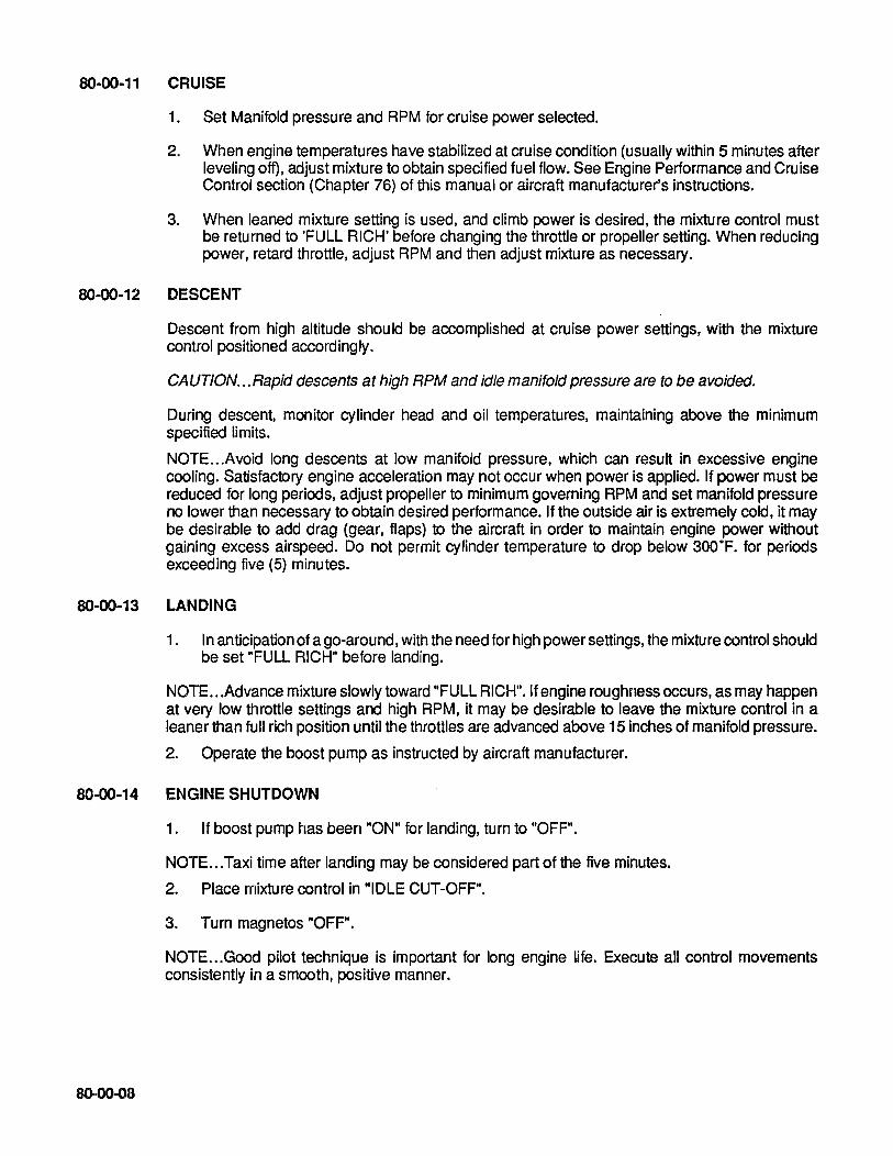
80-00-11 CRUISE
1. Set Manifold pressure and RPM for cruise power selected.
2. When engine temperatures have stabilized at cruise condition (usually within 5 minutes after leveling off), adjust mixture to obtain specified fuel flow. See Engine Performance and Cruise Control section (Chapter 76) of this manual or aircraft manufacturer's instructions.
3. When leaned mixture setting is used, and climb power is desired, the mixture control must be returned to 'FULL RICH' before changing the throttle or propeller setting. When reducing power, retard throttle, adjust RPM and then adjust mixture as necessary.
80-00-12 DESCENT
Descent from high altitude should be accomplished at cruise power settings, with the mixture control positioned accordingly.
CAUTION ... Rapid descents at high RPM and idle manifold pressure are to be avoided.
During descent, monitor cylinder head and oil temperatures, maintaining above the minimum specified limits.
NOTE ... Avoid long descents at low manifold pressure, which can result in excessive engine cooling. Satisfactory engine acceleration may not occur when power is applied. If power must be reduced for long periods, adjust propeller to minimum governing RPM and set manifold pressure no lower than necessary to obtain desired performance. If the outside air is extremely cold, it may be desirable to add drag (gear, flaps) to the aircraft in order to maintain engine power without gaining excess airspeed. Do not permit cylinder temperature to drop below 300·F. for periods exceeding five (5) minutes.
80-00-13 LANDING
1. In anticipation of a go-around, with the need for high power settings, the mixture control should be set "FULL RICH" before landing.
NOTE ... Advance mixture slowly toward "FULL RICH". If engine roughness occurs, as may happen at very low throttle settings and high RPM, it may be desirable to leave the mixture control in a leaner than full rich position until the throttles are advanced above 15 inches of manifold pressure.
2. Operate the boost pump as instructed by aircraft manufacturer.
80-00-14 ENGINE SHUTDOWN
80-00-08
1. If boost pump has been "ON" for landing, turn to "OFF".
NOTE ... Taxi time after landing may be considered part of the five minutes.
2. Place mixture control in "IDLE CUT-OFF".
3. Turn magnetos "OFF".
NOTE ... Good pilot technique is important for long engine life. Execute all control movements consistently in a smooth, positive manner.

INTENTIONALL Y LEFT
BLANK
80"()()-oo

80·10-00 ABNORMAL ENVIRONMENTAL CONDITIONS
The following adverse conditions should be given special attention. They are: cold weather operation, hot weather operation and high altitude ground operation. The information that follows may be helpful to the operator in obtaining satisfactory engine performance while operating in these conditions.
80-10-01 COLD WEATHER OPERATION. (Use Preheat When Ambient Temperature Is Below Freezing)
NOTE ... Prior to operation and/or storage in cold weather ensure engine oil viscosity is SAE 30, 10W30, 15W50 or 20W50. In the event of temporary cold weather operation not justifying an oil change to SAE 30, consideration should be given to hangaring the aircraft between flights.
Engine starting during extreme cold weather is generally more difficult than during warm weather conditions. Cold soaking causes the oil to become thicker (more viscous), making it more difficult for the starter to crank the engine. This results in a slow cranking speed and an abnormal drain on the battery capacity. At low temperatures, gasoline does not vaporize readily, further complicating the starting problem.
WARNING ... Durlng cold weather operation fuel vaporization characteristics are poor. Mismanagement of the auxilary fuel pump or overpriming of the engine could lead to cylinder hydro-static lock.
False starting (failure to continue running after starting) often results in the formation of moisture on the spark plugs due to condensation. This moisture can freeze and must be eliminated either by applying heat to the engine or removing and cleaning the spark plugs.
80-10-02 PREHEATING
80-10-00
Use preheat and auxiliary power unit (APU) to facilitate starting during cold weather and when the engine has been cold soaked at temperatures of 25°F. and below in excess of 2 hours. Successful starts without these aids can be expected at temperatures below normal, provided the engine is in good condition and the ignition and fuel systems are properly maintained.
The following procedures are recommended for preheating, starting, warm-up, run-up and takeoff.
1. Select a high volume hot air heater. Small electric heaters which are inserted into the cowling opening do not appreciably warm the oil and may result in superficial preheating.
WARNING ... Superficial application of preheat to a cold-soaked engine can cause damage to the engine. A minimum of preheat application may warm the engine enough to permit starting but will not de-congeal oil in the sump, lines, cooler, filter, etc. Congealed oil in such lines may require considerable preheat. The engine may start and apparently run satisfactorily, but can be damaged from lack of lubrication due to congealed 011 In various parts of the system. The amount of damage will vary and may not become evident for many hours. On the other hand, the engine may be severely damaged and could fail shortly following application of high power.
Proper proced ures require thorough application of preheat to all parts of the engine. Hot air should be applied directly to the oil sump and external oil lines as well as the cylinders, air intake and oil cooler. Excessive hot air can damage nonmetallic components such as seals, hoses and drive belts, so do not attempt to hasten the preheat process.

Before starting is attempted, turn the engine by hand or starter until it rotates freely. After starting, observe carefully for high or low oil pressure and continue the warm-up until the engine operates smoothly and all controls can be moved freely. Do not close the cowl flaps to facilitate warm-up as hot spots may develop and damage ignition wiring and other components.
2. Hot air should be applied primarily to the oil sump and filter area. The oil drain plug door or panel may provide access to these areas. Continue to apply heat for 15 to 30 minutes and turn the propeller by hand through 6 or 8 revolutions at 5 to 10 minute intervals.
3. Periodically feel the top of the engine and when some warmth is noted, apply heat directly to the upper portion of the engine for approximately five minutes. This will provide sufficient heating of the cylinders and fuel lines to promote better vaporization for starting. If enough heater hoses are available, continue heating the sump area. Otherwise, it will suffice to transfer the source of heat from the sump to the upper part of the engine.
4. Start the engine immediately after completion of the preheating process. Since the engine will be warm, use normal starting procedure. Refer to Section 80-00-02, Item 6, Priming Time requirement.
NOTE ... Since the oil in the oil pressure gauge line may be congealed, as much as 60 seconds may elapse before oil pressure is indicated. If oil pressure is not indicated within one minute, shut the engine down and determine the cause.
5. Operate the engine at 1000 RPM until some oil temperature is indicated. Monitor oil pressure closely during this time and be alert for a sudden increase or decrease. Retard throttle, if necessary to maintain oil pressure below 100 p.s.i. If oil pressure drops suddenly to less than 30 p.s.i, shut down the engine and inspect the lubrication system. If no damage or leaks are noted, preheat the engine for an additional 1 0 to 15 minutes before starting.
6. Before takeoff, run up the engine to 1700 RPM. If necessary, approach this RPM in increments to prevent oil pressure from exceeding 100 p.s.i.
At 1700 RPM, adjust the propeller control to Full Decrease RPM until minimum governing RPM is observed, then return the control to Full Increase RPM. Repeat this procedure three or four times to circulate warm oil into the propeller dome. If the aircraft manufacturer recommends checking the propeller feathering system, move the control to the Feather position, but do not allow the RPM to drop more than 300 RPM below minimum governing speed.
NOTE ... Continually monitor oil pressure during run-up.
7. Check magnetos in the normal manner.
8. When the oil temperature has reached 1 OO·F. and oil pressure does not exceed 80 p.s.i. at 1700 RPM, the engine has been warmed sufficiently to accept full rated power.
CAUTION ... 00 not close the cowl flaps in an attempt to hasten engine warm-up.
NOTE ... Fuel flow will probably be on the high limit: However, this is normal and desirable since the engine will be developing more horsepower at substandard ambient temperatures.
80-10-01
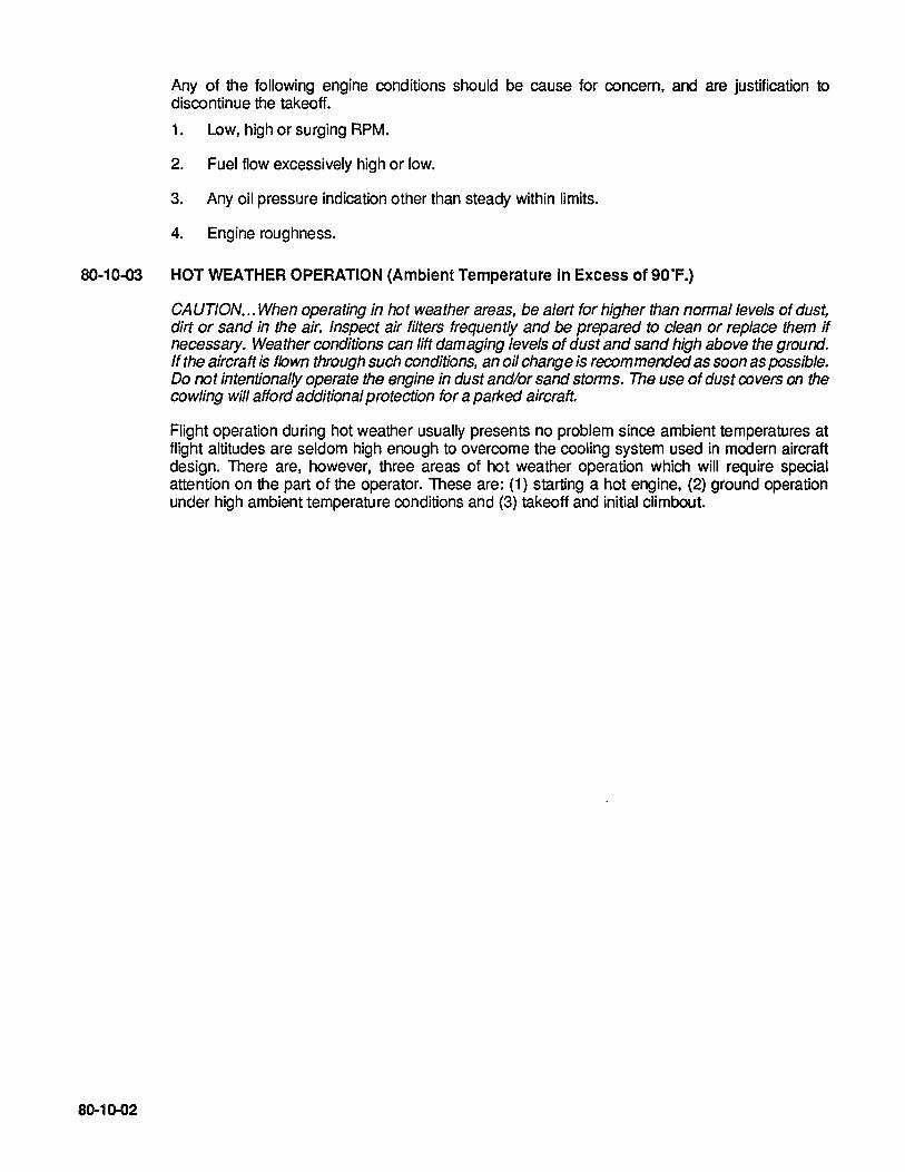
Any of the following engine conditions should be cause for concern, and are justification to discontinue the takeoff.
1. Low, high or surging RPM.
2. Fuel flow excessively high or low.
3. Any oil pressure indication other than steady within limits.
4. Engine roughness.
80·10·03 HOT WEATHER OPERATION (Ambient Temperature In Excess of 90"F.)
80-10-02
CAUTION ... When operating in hot weather areas, be alert for higher than normal levels of dust, dirt or sand in the air. Inspect air filters frequently and be prepared to clean or replace them if necessary. Weather conditions can lift damaging levels of dust and sand high above the ground. If the aircraft is flown through such conditions, an oil change is recommended as soon as possible. Do not intentionally operate the engine in dust and/or sand storms. The use of dust covers on the cowling will afford additional protection for a parked aircraft.
Flight operation during hot weather usually presents no problem since ambient temperatures at flight altitudes are seldom high enough to overcome the cooling system used in modern aircraft deSign. There are, however, three areas of hot weather operation which will require special attention on the part of the operator. These are: (1) starting a hot engine, (2) ground operation under high ambient temperature conditions and (3) takeoff and initial climbout.

1. STARTING A HOT ENGINE. After an engine is shutdown, the temperature of its various components will begin to stabilize. That is, the hotter parts such as cylinders and oil will cool, while other parts will begin to heat up due to lack of air flow, heat conduction, and heat radiation from thoses parts of the engine which are cooling. At some time period following engine shutdown, the entire unit will stabilize near the ambient temperature. This time period will be determined by temperature and wind conditions and may be as much as several hours. This heat soaking is generally at the extreme from 30 minutes to one hour following shutdown. During this time, the fuel system will heat causing the fuel in the pump and lines to "boil" or vaporize. During subsequent starting attempts, the fuel pump will initially be pumping a combination of fuel and fuel vapor. At the same time, the injection nozzle lines will be filled with varying amounts of fumes and vapor. Until the entire fuel system becomes filled with liquid fuel, difficult starting and unstable engine operation can normally be expected.
The state of the fuel itself can affect these fuel vapor conditions. Fresh fuel contains a concentration of volatile ingredients. The higher the concentration, the more readily the fuel will vaporize and the probelm with the vapor in the fuel will be more severe. Time, heat or exposure to altitude will "age" aviation gasoline causing the volatile ingredients to dissipate. This reduces the tendency of fuel to vaporize and, may induce problems with starting. If the volatile condition reaches a low enough level, starting may become difficult due to poor vaporization at the fuel nozzles since the fuel must vaporize in order to combine with oxygen in the combustion process.
The operator, by being aware of these conditions, can take certain steps to cope with problems associated with hot weather/hot engine starting. The primary objective should be that of permitting the system to cool. Lower power settings during the landing approach, when practical, will allow some cooling prior to the next start attempt. Reducing ground operating to a minimum is desired to keep engine temperatures down. Cowl flaps should be opened fully while taxiing. The aircraft should be parked so as to face into the wind to take advantage of the cooling effect. Restarting attempts will be the most difficult from 30 minutes to one hour after shutdown. Following that interval the fuel vapor will be less pronounced and normally will present less of a restart problem.
2. GROUND OPERATION IN HIGH AMBIENT TEMPERATURE CONDITIONS. Oil and cylinder temperatures should be monitored closely during taxiing and engine run-up. Operate with cowl flaps full open. Do not operate the engine at high RPM except for necessary operational checks. If takeoff is not to be made immediately following engine run-up, the aircraft should be faced into the wind with engine idling at -900-1 000 RPM. It may be desirable to operate the fuel boost pumps to assist in suppressing fuel vaporization and provide more stable fuel pressure during taxiing and engine run-up.
3. TAKEOFF AND INITIAL CLiMBOUT. Temperatures should be closely monitored and sufficient airspeed must be maintained to provide proper cooling of the engine.
CAUTION ... Reduced engine power will result from higher density altitude associated with high temperature.
80·10-04 GROUND OPERATION AT HIGH ALTITUDE AIRPORTS
Because of insufficient air density at altitudes, oil pressure, oil temperature and cylinder head temperature gauges should be carefully observed to prevent engine overheating.
80-10-03

80-10-04
On the 10-SSO-E, F & L engines, the altitude compensating fuel pump will automatically lean fuel flow, with mixture control in the full rich position. On the 10-SSO-D, some manual leaning may be required for engine operation.
If higher than desired temperatures are experienced during the climb phase the pilot may elect to establish a lower angle of attack, or higher climb speed, consistant with safety and thereby provide increased cooling for the engine.
80-20-00 EMERGENCY PROCEDURES
80-20-01
If a malfunction should occur in flight, certain remedial actions may eliminate or reduce the problem. Some malfunctions which might conceivably occur are listed in this section. Recommended corrective action is also included, however, it should be recognized that no single prodecure will necessarily be applicable to every situation.
A thorough knowledge of the aircraft and engine systems will be an invaluable asset to the pilot in assessing a given situation and dealing with it accordingly.
ENGINE FIRE DURING START
If flames are observed in the induction or exhaust system during engine starting, follow the aircraft manufacturer's instructions in their Pilot's Operating Handbook.
80-20-02 ENGINE ROUGHNESS
Observe engine for visible damage or evidence of smoke or flame. Extreme roughness may be indicative of propeller blade failure. If any of these characteristics are noted, follow aircraft manufacturer's instructions.
1. Engine Instruments - Check. If abnormal indications appear, proceed according to Abnormal Engine Instrument Indications (80-20-03,04&05).
2. Mixture - Adjust as appropriate to power setting being used. Do not arbitrarily go to "Full Rich", as the roughness may be caused by an over rich mixture.
3. Magnetos - Check On.
If engine roughness does not disappear after the above, the following steps should be taken to evaluate the ignition system.
1. Throttle - Reduce power until roughness becomes minimal.
2. Magnetos -Turn OFF, then ON, one ata time. If engine smoothes out while running on single ignition, adjust power as necessary and continue. Do not operate the engine in this manner any longer than absolutely necessary. The airplane should be landed as soon as practical and the engine repaired.
If no improvement in engine operation is noted while opeating on either magneto, return all magneto switches to ON.
CAUTION ... The engine may quit completely when one magneto is switched off if the other magneto is faulty. DO NOT tum magnetos immediately "ONN. Close the throttle to idle and move the mixture to idle cutoff before turning the magnetos on. This may prevent a severe backfire from occurring. Once magnetos are turned back on, advance mixture and throttle to previous settings.
WARNING •• Jf roughness is severe or if the cause cannot be determined, engine failure may be imminent. In this case, it is recommended that the aircraft manufacturer's emergency procedure be employed. In any event, further damage may be minimized by operating at a reduced power setting.
80-20-01

80·20-03 HIGH CYLINDER HEAD TEMPERATURE
1. Mixture - Increase fuel flow.
2. Cowl Flaps - Open.
3. Airspeed -Increase to normal climb or cruise speed.
CAUTlON ... 1f temperature cannot be maintained within limits, reduce power, land as soon as practical, and have the engine inspected before further flight.
80-20-04 HIGH OIL TEMPERATURE
NOTE ... Prolonged high oil temperature indications will usually be accompanied by a drop in oil pressure. If oil pressure remains normal, then a high temperature indication may be caused by a faulty gauge or thermocouple. If the oil pressure drops as temperature increases, proceed as follows;
1. Cowl Flaps - Open
2. Airspeed -Increase to normal climb or cruise speed.
3. Power - Reduce if steps 1 and 2 do not lower oil temperature.
WARNING .. .If these steps do not restore oil temperature to normal, an engine failure or severe damage can result. In this case it is recommended that the aircraft manufacturer's Instruction be followed.
80·20-05 LOW OIL PRESSURE
CAUTION ... 1f the oil pressure drops unexplainably from the normal indication, monitor temperature and pressure closely and have the engine inspected at termination of the flight.
WARNING .. .If oil pressure drops below 30 p.s.!., an engine failure should be anticipated. Follow aircraft manufacturer's emergency procdures.
80-20-06 IN-FLIGHT RESTARTING
80-20-02
CAUTION ... Actual shutdowns of an engine for practice or training purposes should be minimized. Whenever engine failure is to be simulated, it should be done by reducing power.
CAUTION ... A few minutes exposure to temperatures and airsp'eeds at flight altitudes can have the same effect on an inoperative engine as hours of cold-soak in sub-Arctic condition. If the engine must be restarted, consideration should be given to descending to warmer air. Closely monitor for excessive oil pressure as the propeller is unfeathered. Allow the engine to warm-up at minimum governing RPM and 15 inches Hg. (manifold pressure).

The following procedure is recommended for in-flight restarting.
1. Mixture -IDLE CUT-OFF.
2. Fuel Selector Valve - ON.
3. Fuel Boost Pump - ON.
4. Alternator Switch - OFF.
5. Throttle - NORMAL COLD START POSITION (1/2 OPEN).
6. Propeller Control - MOVE FORWARD OF THE FEATHERING DETENT TO MID-RANGE.
7. Magneto/Start Switch - START.
8. On 10-550-0, Mixture - FORWARD AS ENGINE STARTS. On 1Q-550-E, F & L, Mixture - FULL RICH.
9. Throttle - AS NECESSARY TO PREVENT OVERS PEED; Warm-up at 15 in. Hg. manifold pressure.
10. Oil Pressure, Oil Temperatures - NORMAL INDICATION.
11. Alternator Switch - ON.
12. Power - AS REQUIRED.

80-20-04
INTENTIONALL Y
LEFT
BLANK

CHAPTER 81 TURBINES
81-00-00 GENERAL (NOT APPLICABLE)
81-00-01

81-00-00 GENERAL
The 10-550 model engines are naturally aspirated engines not utilizing a turbocharger.
81-00-02


www.continentalmotors.aeroContinental Motors, Inc.