Embed Size (px)
Citation preview
CONTENTS
PRECAUTIONS FOR HANDLING THE INVERTER
1 . ACCEPTANCE INSPECTION ......................................................................................................................... 1
2 . STRUCTURE ................................................................................................................................................... 2 2.1 Structure ... . . . . . . . . . . . . . . . . . . . . . . . . . . . . . . . . . . . . . . . . . . . . . . . . . . . . . . . . . . . . . . . . . . . . . . . . . . . . . . . . . . . . . . . . . . . . . . . . . . . . . . . . . . . . . . . . . . . . . . . . . . . . . . . . . . . . . . . . . . . . . . . . . 2 2.2 Removal and Reinstallation of the Front Cover ...................................................................................... 3 2.3 Removal and Reinstallation of the Parameter Unit ................................................................................. 4 2.4 Removal and Reinstallation of the Accessory Cover .............................................................................. 4 2.5 Handling of the FR-PUOI E Parameter Unit ............................................................................................. 5 2.6 Handling of the FR-ZRWE Parameter Copy Unit .................................................................................... 5
3 . INSTALLATION ............................................................................................................................................... 7 3.1 Transportation ........................................................................................................................................... 7 3.2 Place of Installation ... . . . . . . . . . . . . . . . . . . . . . . . . . . . . . . . . . . . . . . . . . . . . . . . . . . . . . . . . . . . . . . . . . . . . . . . . . . . . . . . . . . . . . . . . . . . . . . . . . . . . . . . . . . . . . . . . . . . . . . . . . . . . . . . 7 3.3 Installation Direction and Clearances ...................................................................................................... 8
4 . WIRING ............................................................................................................................................................ 9 4.1 Wiring Instructions .................................................................................................................................... 9 4.2 Main Circuit ............................................................................................................................................. 11 4.3 Control Circuit .. . . . . . . . . . . . . . . . . . . . . . . . . . . . . . . . . . . . . . . . . . . . . . . . . . . . . . . . . . . . . . . . . . . . . . . . . . . . . . . . . . . . . . . . . . . . . . . . . . . . . . . . . . . . . . . . . . . . . . . . . . . . . . . . . . . . . . . . 15
5 . OPERATION .................................................................................................................................................. 17 5.1 Operation Mode ...................................................................................................................................... 17 5.2 Pre-Operation Checks ............................................................................................................................ 17 5.3 Pre-Operation Settings ........................................................................................................................... 18 5.4 Check Points during Test Run ............................................................................................................... 20
6 . PARAMETER UNIT ....................................................................................................................................... 22 6.1 Structure of the Parameter Unit ............................................................................................................. 22 6.2 Installation of the Parameter Unit .......................................................................................................... 23 6.3 Functions of the Parameter Unit ............................................................................................................ 26 6.4 Operation ................................................................................................................................................. 28
Running the Motor from the Parameter Unit ..................................................................................... 28
Changing or Checking the Function (Parameter) Set Values .......................................................... 36
Calibrating the Frequency Meter ........................................................................................................ 48 Adjusting the Bias and Gain of the Frequency Setting Signal ......................................................... 50
6.5 Parameters ... . . . . . . . . . . . . . . . . . . . . . . . . . . . . . . . . . . . . . . . . . . . . . . . . . . . . . . . . . . . . . . . . . . . . . . . . . . . . . . . . . . . . . . . . . . . . . . . . . . . . . . . . . . . . . . . . . . . . . . . . . . . . . . . . . . . . . . . . . . . 52 Parameter List ..................................................................................................................................... 52 Explanation of the Parameters ........................................................................................................... 56 5-Point Flexible v/f Characteristic ...................................................................................................... 72 PU Disconnection Detection Function ............................................................................................... 74 Magnetic Flux Vector Control ............................................................................................................. 75
Switch-over Function ... . . . . . . . . . . . . . . . . . . . . . . . . . . . . . . . . . . . . . . . . . . . . . . . . . . . . . . . . . . . . . . . . . . . . . . . . . . . . . . . . . . . . . . . . . . . . . . . . . . . . . . . . . . . . . . . . . . . . . . . 78
. Changing the Monitor Screen ............................................................................................................ 32
. Applying the Help Function ................................................................................................................ 38
. V/F Slip Control ................................................................................................................................... 77
CONTENTS
7 . MAINTENANCE AND INSPECTION ............................................................................................................ 79 -
7.1 Precautions for Maintenance and Inspection ........................................................................................ 79 7.2 Check Items ............................................................................................................................................ 79 7.3 Measurement of Main Circuit Voltages. Currents and Powers ............................................................. 82 7.4 Checking the Inverter and Converter Modules ...................................................................................... 84 7.5 Replacement of Parts ............................................................................................................................. 85
8 . TROUBLESHOOTING ................................................................................................................................... 86 8.1 Clearing Up the Cause of Fault .............................................................................................................. 86 8.2 Faults and Check Points ......................................................................................................................... 87 8.3 Protective Functions ............................................................................................................................... 88 8.4 Alarm Code Output .................................................................................................................................. 90
9 . OPTIONS ....................................................................................................................................................... 91 9.1 Option List ............................................................................................................................................... 91 9.2 Inboard Dedicated Options ..................................................................................................................... 93 9.3 External Dedicated Options .................................................................................................................... 96
10 . SPECIFICATIONS ....................................................................................................................................... 99 10.1 Standard Specifications ........................................................................................................................ 99 10.2 Block Diagram ..................................................................................................................................... 103 10.3 Terminals ............................................................................................................................................. 104 10.4 Terminal Block Arrangement .............................................................................................................. 106 10.5 Outline Drawings ................................................................................................................................. 110 10.6 FR-PU02( E) Parameter Unit Dimension Diagram ............................................................................. 112 10.7 Peripheral Device List ......................................................................................................................... 113 10.8 Selecting the Rated Sensitivity Current for the Earth Leakage Circuit Breaker .............................. 114
11 . APPENDIX ................................................................................................................................................. 115 11.1 Countermeasures for Noise ............................................................................................................... 115 1 1 . 2 Leakage currents ................................................................................................................................ 116
PRECAUTIONS FOR HANDLING THE INVERTER
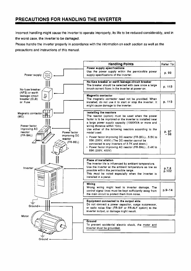
Incorrect handling might cause the inverter to operate improperly, its life to be reduced considerably, and in the worst case, the inverter to be damaged. Please handle the inverter properly in accordance with the information on each section as well as the precautions and instructions of this manual.
Handling Points Power supply specifications Use the power supply within the permissible power supply specifications of the inverter. Power supply @ . :I Refer To:
- No-fuse breaker or earth leakage circuit breaker The breaker should be selected with care since a large inrush current flows in the inverter at power on. p. 1,
No-fuse breaker (NFB) or earth leakage circuit
or Fuse installed, do not use it to start or stop the inverter. It p. 113 The magnetic contactor need not be provided. When breaker (ELB) Magnetic contactor & *
might cause damage to the inverter.
Magnetic contactor Installing the reactors (MC) The reactor (option) must be used when the power
1 1 1 factor is to be improved or the inverter is installed near
Power factor
reactor (FR-BAL) improving DC
(FR-BEL)
1 1 1
a large power supply capacity (lOOOKVA or more and wiring distance within 10m). Use either of the following reactors according to the model used:
Power factor improving DC reactor (FR-BEL) ... 5.5K to 55K (200V, 400V) (The DC reactor cannot be connected to any inverters of 3.7K and down.)
55K (200V, 400V) Power factor improving AC reactor (FR-BAL) ... 0.4K to
p. 97 - 98
Place of installation The inverter life is influenced by ambient temperature. Use the inverter at the ambient temperature as low as possible within the permissible range. p . 1 0 2 p . 7 3 This must be noted especially when the inverter is installed in a panel.
Wrong wiring might lead to inverter damage. The control signal lines must be kept sufficiently away from P.9-14 the main circuit to protect them from noise.
Equipment connected to the output side Do not connect a power capacitor, surge suppressor, or radio noise filter (FR-BIF or FR-ALF option) to the inverter output, or damage might result.
To prevent accidental electric shock, the motor and inverter must be grounded.
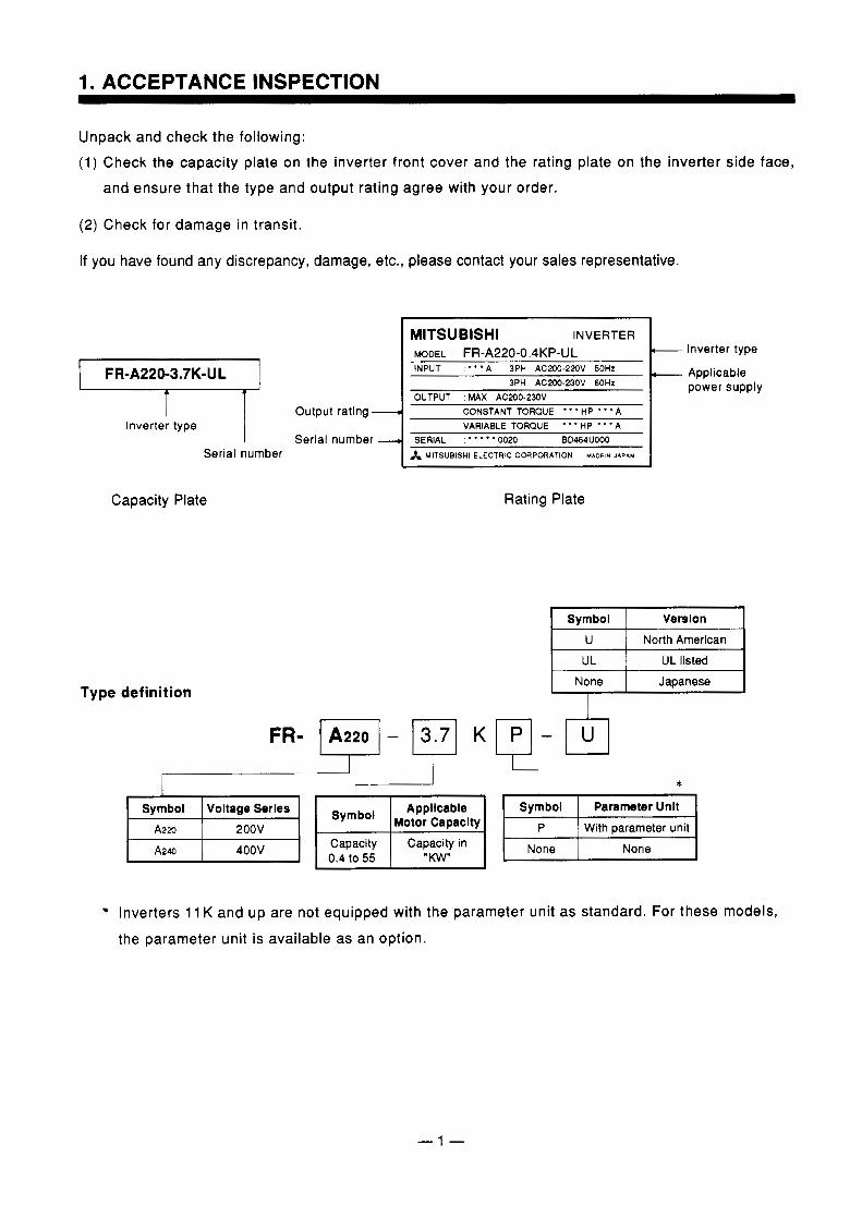
Unpack and check the following: (1) Check the capacity plate on the inverter front cover and the rating plate on the inverter side face,
and ensure that the type and output rating agree with your order.
(2) Check for damage in transit.
If you have found any discrepancy, damage, etc., please contact your sales representative.
Serial number
Capacity Plate
Type definition
Output rating.
Serial number
r MITSUBISHI INVERTER MODEL FR-A220-0.4KP-UL c INPUT ' * * * A 3PH AC200-220V 50HZ
3PH AC200-23OV 60Hz OUTPUT :MAX AC200-230V
d
VARIABLE TORQUE " 'HP " ' A CONSTANT TORQUE " ' H P " ' A
--L SERIAL :""'0020 BD464UOOD A MITSUBISHI ELECTRIC CORPORATION MADEIN JAPAN
FR- - K
F33 Symbol Voltage Serles
Capacity Capacity in 0.4 to 55 I "Kw"
Rating Plate
I Inverter type
Applicable power supply
Symbol Verslon U North American
None Japanese , I
'I * Symbol Parameter Unlt
P With parameter unit None I
Inverters 11 K and up are not equipped with the parameter unit as standard. For these models,
the parameter unit is available as an option.
- 1 -
2. STRUCTURE
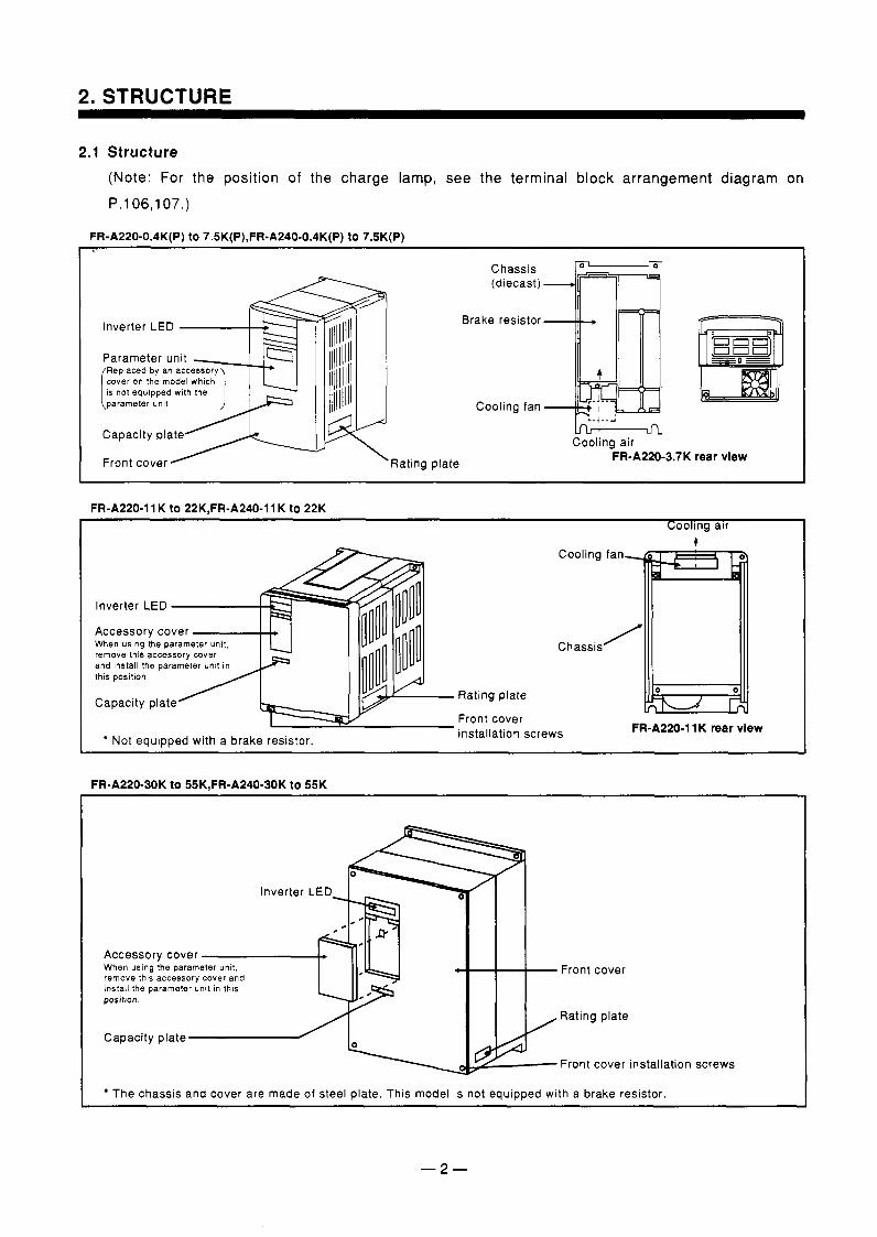
2.1 Structure (Note: For the position of the charge lamp, see the terminal block arrangement diagram on P.106,107.)
FR-A220-0.4K(P) to 7.5K(P),FR-A240-0.4K(P) to 7.5K(P)
Inverter LED \
Parameter unit m
d l 5 Rating plate Cooling air
FR-A220-3.7K rear vlew
FR-A220-11 K to 22K,FR-A240-11 K to 22K Coolmg alr
Cooling
Inverter LED - 4 F I Accessory cover When using the parameter unit, remove this accessory cover and install the parameter unlt In thls positlon.
Capacity plate
Not equipped with a brake resistor.
Chassis
Rating plate
Front cover installation screws FRA220-11K rear view
FR-A220-30K to 55K.FR-A240-30K to 55K
Accessory cover When using the param remove this accessory cover and install the parameter unlt in thls positlon.
Capacity plate A0 Front cover
Rating plate
Front cover installation screws
The chassis and cover are made of steel plate. This model is not equipped with a brake resistor.
-2-
2. STRUCTURE
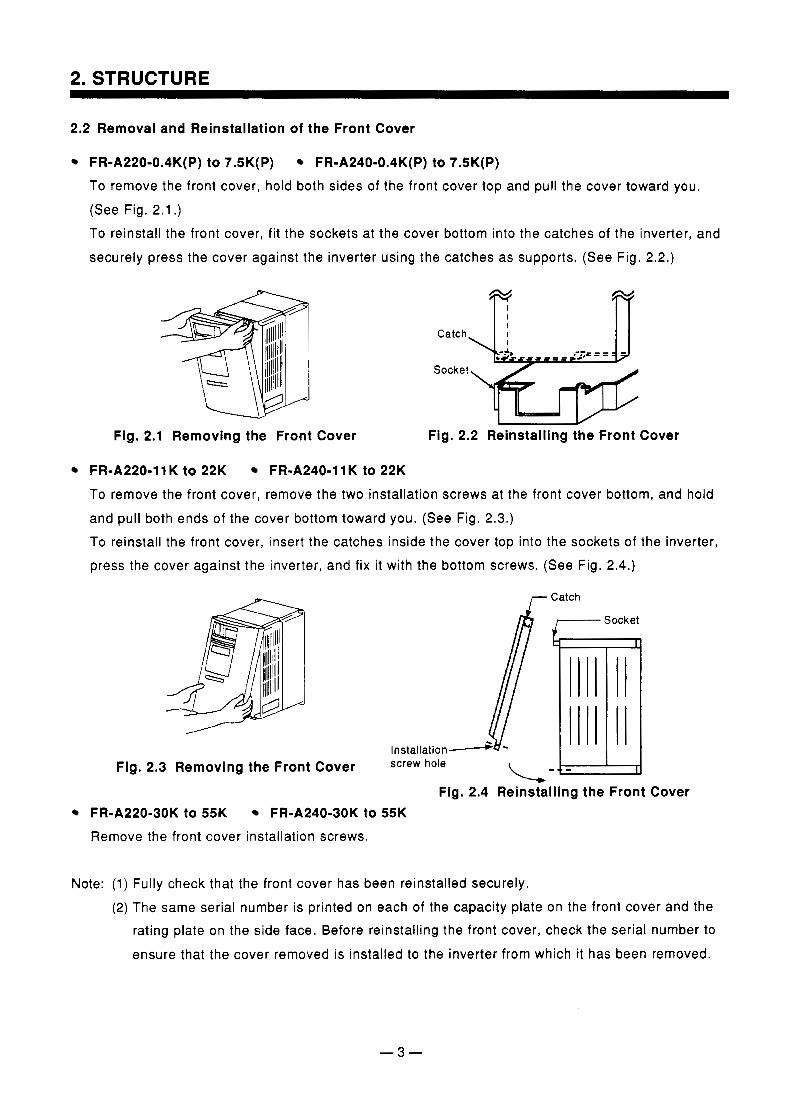
2.2 Removal and Reinstallation of the Front Cover
FR-A220-0.4K(P) to 7.5K(P) FR-A240-0.4K(P) to 7.5K(P) To remove the front cover, hold both sides of the front cover top and pull the cover toward you. (See Fig. 2.1 .) To reinstall the front cover, fit the sockets at the cover bottom into the catches of the inverter, and
securely press the cover against the inverter using the catches as supports. (See Fig. 2.2.)
Catch \
Socket
Fig. 2.1 Removing the Front Cover Fig. 2.2 Reinstalling the Front Cover
FR-A220-11 K to 22K FR-A240-11 K to 22K To remove the front cover, remove the two installation screws at the front cover bottom, and hold and pull both ends of the cover bottom toward you. (See Fig. 2.3.)
To reinstall the front cover, insert the catches inside the cover top into the sockets of the inverter, press the cover against the inverter, and fix it with the bottom screws. (See Fig. 2.4.)
I- Catch
Socket
Fig. 2.3 Removing the Front Cover hole
Fig. 2.4 Reinstalling the Front Cover FR-A220-30K to 55K FR-A240-30K to 55K Remove the front cover installation screws.
Note: (1) Fully check that the front cover has been reinstalled securely. (2) The same serial number is printed on each of the capacity plate on the front cover and the
rating plate on the side face. Before reinstalling the front cover, check the serial number to
ensure that the cover removed is installed to the inverter from which it has been removed.
When the inverter surface is stained with fingermarks, oil and/or the like, gently wipe that area with a soft cloth soaked with a neutral detergent or ethanol. Note: (1) Do not use any solvent, such as acetone, benzene and toluene, that will cause the inverter
surface to dissolve and the paint to peel. Note: (2) Do not clean the lens of the inverter LED with a detergent or alcohol which will easily affect
the lens.
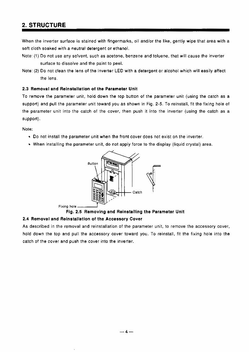
2.3 Removal and Reinstallation of the Parameter Unit To remove the parameter unit, hold down the top button of the parameter unit (using the catch as a support) and pull the parameter unit toward you as shown in Fig. 2-5. To reinstall, fit the fixing hole of the parameter unit into the catch of the cover, then push it into the inverter (using the catch as a support).
Note: Do not install the parameter unit when the front cover does not exist on the inverter. When installing the parameter unit, do not apply force to the display (liquid crystal) area.
Fixing hole - Fig. 2.5 Removing and Reinstalling the Parameter Unit
2.4 Removal and Reinstallation of the Accessory Cover As described in the removal and reinstallation of the parameter unit, to remove the accessory cover, hold down the top and pull the accessory cover toward you. To reinstall, fit the fixing hole into the catch of the cover and push the cover into the inverter.
- 4 -
. ..
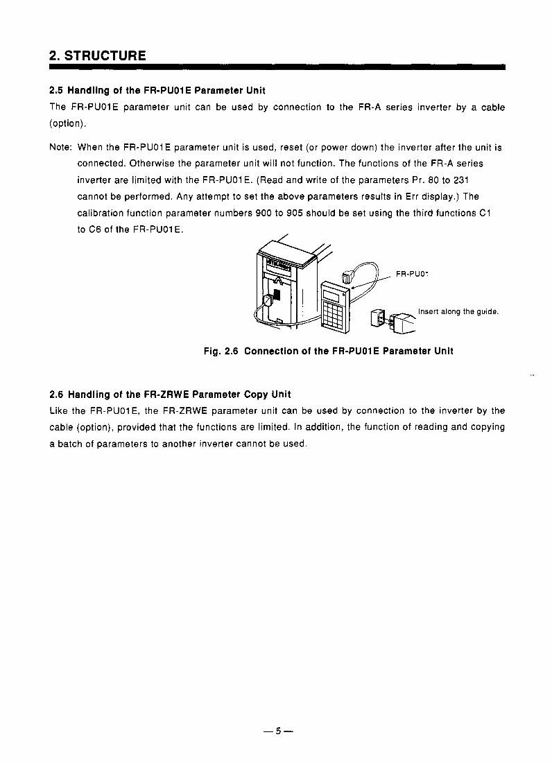
2.5 Handling of the FR-PUOIE Parameter Unit The FR-PUOlE parameter unit can be used by connection to the FR-A series inverter by a cable (option).
Note: When the FR-PUOlE parameter unit is used, reset (or power down) the inverter after the unit is connected. Otherwise the parameter unit will not function. The functions of the FR-A series
inverter are limited with the FR-PUO1 E. (Read and write of the parameters Pr. 80 to 231 cannot be performed. Any attempt to set the above parameters results in Err display.) The calibration function parameter numbers 900 to 905 should be set using the third functions C1 to C6 of the FR-PUO1 E. ,
Insert along the guide.
Fig. 2.6 Connection of the FR-PUOlE Parameter Unit
2.6 Handling of the FR-ZRWE Parameter Copy Unit Like the FR-PUO1 E, the FR-ZRWE parameter unit can be used by connection to the inverter by the cable (option), provided that the functions are limited. In addition, the function of reading and copying a batch of parameters to another inverter cannot be used.

MEMO
-6-
3. INSTALLATION
3.1 Transportation During transportation, handle the inverter carefully to protect it from damage. Hold the inverter so as not to apply force only to the front cover of the inverter.
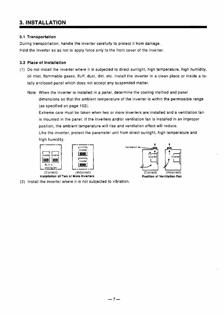
3.2 Place of Installation (1) Do not install the inverter where it is subjected to direct sunlight, high temperature, high humidity,
oil mist, flammable gases, fluff, dust, dirt, etc. Install the inverter in a clean place or inside a to-
tally enclosed panel which does not accept any suspended matter.
Note: When the inverter is installed in a panel, determine the cooling method and panel dimensions so that the ambient temperature of the inverter is within the permissible range (as specified on page 102). Extreme care must be taken when two or more inverters are installed and a ventilation fan is mounted in the panel. If the inverters and/or ventilation fan is installed in an improper position, the ambient temperature will rise and ventilation effect will reduce. Like the inverter, protect the parameter unit from direct sunlight, high temperature and high humidity.
r--- 1
(Correct) (Incorrect)
Ventilation
(Correct)
t
(Incorrect) Installation of Two or More inverters Position of Ventilation Fan
(2) Install the inverter where it is not subjected to vibration.
-7-
3. INSTALLATION
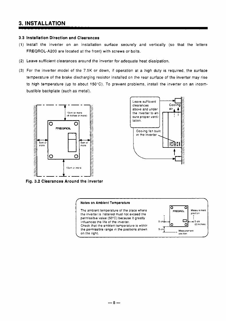
3.3 Installation Direction and Clearances (1) Install the inverter on an installation surface securely and vertically (so that the letters
FREQROL-A200 are located at the front) with screws or bolts.
(2) Leave sufficient clearances around the inverter for adequate heat dissipation.
(3) For the inverter model of the 7.5K or down, if operation at a high duty is required, the surface temperature of the brake discharging resistor installed on the rear surface of the inverter may rise to high temperature (up to about 15OOC). To prevent problems, install the inverter on an incom-
bustible backplate (such as metal). f
Leave sufficient clearances above and under the inverter to en- sure proper venti- lation.
L Cooling fan built
Fig. 3.2 Clearances Around the Inverter
r . Notes on Ambient Temperature
The ambient temperature of the place where the inverter is installed must not exceed the permissible value (50°C) because it greatly influences the life of the inverter. 5 cm 5 crn Check that the ambient temperature is within 7
position
(2 inches)
the permissible range in the positions shown 5cmI x Measurement on the right. posltion
-8-
4. WIRING
4.1 Wiring Instructions Note the following when wiring to prevent miswiring and misuse.
Notes on Wiring (1) The power must not be applied to the output terminals (U, V, W) , otherwise the inverter will
be damaged. (2) Connect only the recommended optional brake resistor between the terminals P and PR. In
addition, these terminals must not be shorted.
(3) Use sleeved solderless terminals for the power supply and motor cables. (4) The common terminals SD, 5 and SE of the control circuit (isolated from each other) must
not be grounded. ( 5 ) Use shielded or twisted cables for connection to the control circuit terminals and run them
away from the main and power circuits (such as 200V relay sequence circuit). (6) When rewiring after operation, make sure that the inverter LED has gone off and that the
charge lamp on the printed circuit board or beside the terminal block has gone off. (7) The cable size for connection to the control circuit terminals should be 0.75mm2. Run the ca-
bles so that they do not occupy much of the control box terminal block space. ( 8 ) Cut off the wiring cover (protective bush) windows using nippers or a cutter when running the
cables. (9) When the power supply voltage is special (400V class), change the connection of the jumper
in the internal transformer, according to the variation around 400V.
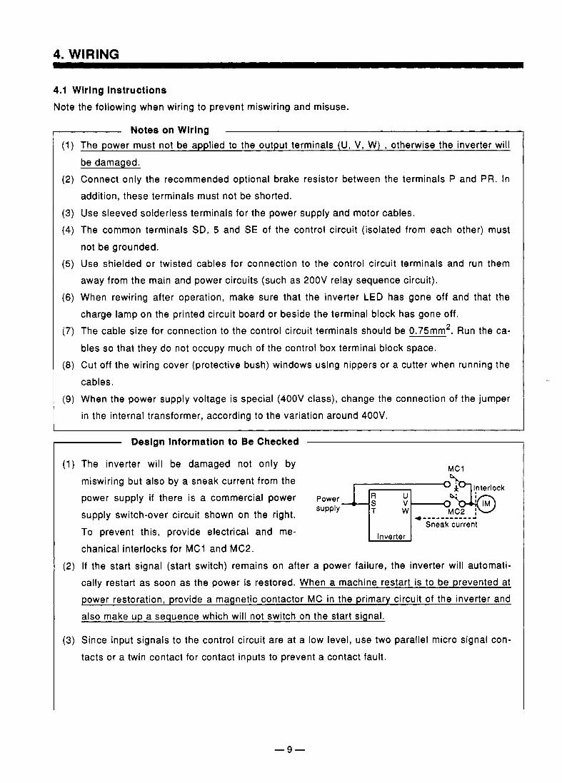
Design Information to Be Checked
(1) The inverter will be damaged not only by miswiring but also by a sneak current from the power supply if there is a commercial power supply Power ! m " ; ' " c k
supply switch-over circuit shown on the right. To prevent this, provide electrical and me- chanical interlocks for MC1 and MC2.
MC1
MC2 * -__-_--____ 4
Sneak current Inverter
(2) If the start signal (start switch) remains on after a power failure, the inverter will automati- cally restart as soon as the power is restored. When a machine restart is to be prevented at power restoration, provide a magnetic contactor MC in the primary circuit of the inverter and also make up a sequence which will not switch on the start signal.
(3) Since input signals to the control circuit are at a low level, use two parallel micro signal con- tacts or a twin contact for contact inputs to prevent a contact fault.

4. WIRING
(4) Do not apply a voltage to the contact input terminals (e.9. STF) of the control circuit. (5) Do not apply a voltage directly to the alarm output signal terminals (A, B, C). Apply a voltage
via a relay coil, lamp, etc. to these terminals.
- 10-
4. WIRING
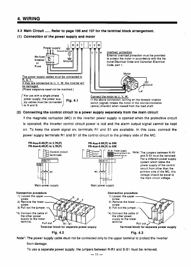
4.2 Main Circuit ..... Refer to page 106 and 107 for the terminal block arrangement. (1) Connection of the power supply and motor
External overload protection must be provided to protect the motor in accordance with the Na- tional Electrical Code and Canadian Electrical
The power supply cables must be connected to R, S, T. If they are connected to U, V, W, the inverter will be damaged. (Phase sequence need not be matched.)
[ 1 nd
For use with a single-phase power supply, the power sup- ply cables must be connected to R and S.
Connect the motor to U, V, W.
switch (signal) rotates the motor in the counterclockwise (arrow) direction when viewed from the load shaft.
Fig. 4.1 In the above connection, turning on the forward rotation
(2) Connecting the control circuit to a power supply separately from the main circuit If the magnetic contactor (MC) in the inverter power supply is opened when the protective circuit is operated, the inverter control circuit power is lost and the alarm output signal cannot be kept on. To keep the alarm signal on, terminals R1 and S1 are available. In this case, connect the power supply terminals R1 and S1 of the control circuit to the primary side of the MC.
FR-AwO.~K(P) to 3.7K(P) FR-A*0.4K(P) to 3.7K(P)
Control circuit
Main power supply
FR-AZZO-SSK(P) to 55K FR-Az@-SSK(P) to 55K
%for Note: The jumpers between R-R1 and S-S1 must be removed. For a different power supply system which takes the power supply of the control circuit from other than the primary side of the MC, this voltage should be equal to the main circuit voltage.
Main power supply
Connection procedure 1) Loosen the upper - 0
screw. /" .s T
Remove the lower screw. Pull out the jumper. ,y# Connect the cable of
Connection procedure 1 ) Loosen the upper -
screw. Remove the lower screw. Pull out the jumper.
Connect the cable of the other power supply to the lower terminal.
the other power supply to the lower terminal. J Pull out. 'T, R1 S1 -
Terminal block for seperate power supply Terminal block for seperate power supply
Fig. 4.2 Fig. 4.3 Note': The power supply cable must not be connected only to the upper terminal to protect the inverter
from damage. To use a seperate power supply, the jumpers between R-R1 and S-SI must be removed.
- 11 -
4. WIRING
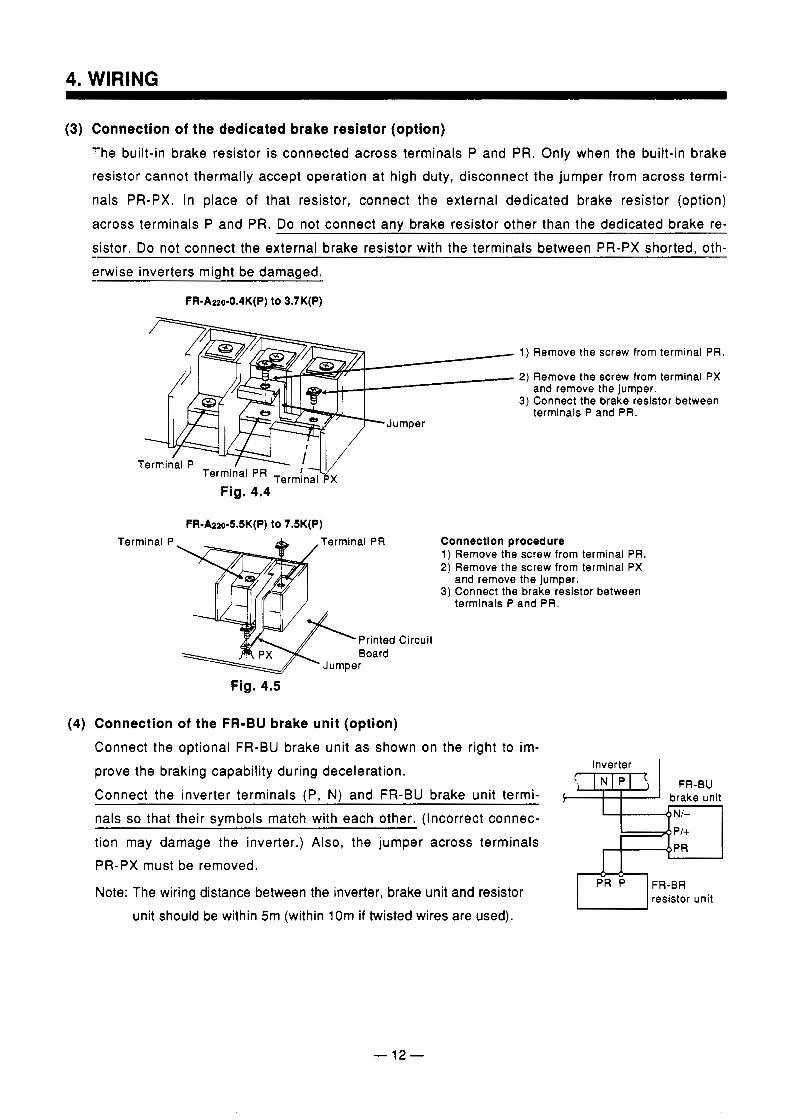
(3) Connection of the dedicated brake resistor (option) The built-in brake resistor is connected across terminals P and PR. Only when the built-in brake resistor cannot thermally accept operation at high duty, disconnect the jumper from across termi-
nals PR-PX. In place of that resistor, connect the external dedicated brake resistor (option) across terminals P and PR. Do not connect any brake resistor other than the dedicated brake re- sistor. Do not connect the external brake resistor with the terminals between PR-PX shorted, oth- erwise inverters miaht be damaaed.
FR-Azo-0.4K(P) to 3.7K(P)
Terminal PR Terminal px
Terminal P
Fig. 4.4
FR-A220-5.5K(P) to 7.5K(P) m ,Terminal PR
Printed Board
Jumper
Fig. 4.5
Remove the
Remove the and remove
screw from
screw from the iumDer.
terminal PR.
terminal PX
3) Connect the brake resistor between terminals P and PR.
Connection procedure 1) Remove the screw from terminal PR. 2) Remove the screw from terminal PX
3) Connect the brake resistor between and remove the jumper.
terminals P and PR.
Circuit
Connection of the FR-BU brake unit (option) Connect the optional FR-BU brake unit as shown on the right to im- prove the braking capability during deceleration. Connect the inverter terminals (P, N) and FR-BU brake unit termi- nals so that their symbols match with each other. (Incorrect connec- tion may damage the inverter.) Also, the jumper across terminals PR-PX must be removed.
Note: The wiring distance between the inverter, brake unit and resistor unit should be within 5m (within 10m if twisted wires are used).
Inverter I
$-$ET1 brake unit
P’rb-1 FR-BR resistor unit
- 12-
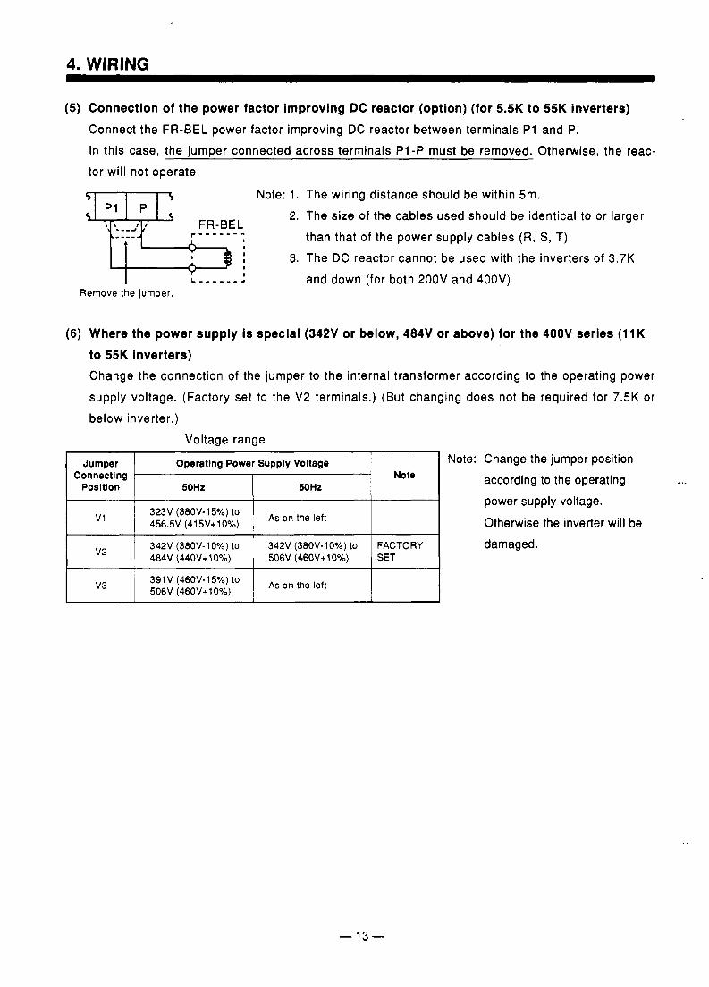
(5) Connection of the power factor improving DC reactor (option) (for 5.5K to 55K inverters) Connect the FR-BEL power factor improving DC reactor between terminals P i and P. In this case, the jumper connected across terminals P1-P must be removed. Otherwise, the reac- tor will not operate.
‘ ‘.--aJ FR-BEL r - - - - - - -
I I I I
I L , , , , , - a
Remove the jumper.
Note: 1. 2.
3.
The wiring distance should be within 5m. The size of the cables used should be identical to or larger than that of the power supply cables (R, S , T). The DC reactor cannot be used with the inverters of 3.7K and down (for both 200V and 400V).
(6) Where the power supply is special (342V or below, 484V or above) for the 400V series (11K to 55K inverters) Change the connection of the jumper to the internal transformer according to the operating power supply voltage. (Factory set to the V2 terminals.) (But changing does not be required for 7.5K or below inverter.)
Voltage range
Jumper
60HZ 50Hz Posltlon
Note: Change the jumper position Operatlng Power Supply Voltage Connecting Note according to the operating
power supply voltage. v1 323V (380V-15%) to
Otherwise the inverter will be 456.5V (415V+10%) As on the ,eft
v2 342V (380V-10°/o) to SET 506V (46OV+1O0/o) 484V (44OV+1O0/o)
damaged. FACTORY 342V (38OV-lOYo) to
I v3 ~ 506V (460V+10%) 1 391 V (46OV-15%) to As on the ,eft
- 13-
4. WIRING
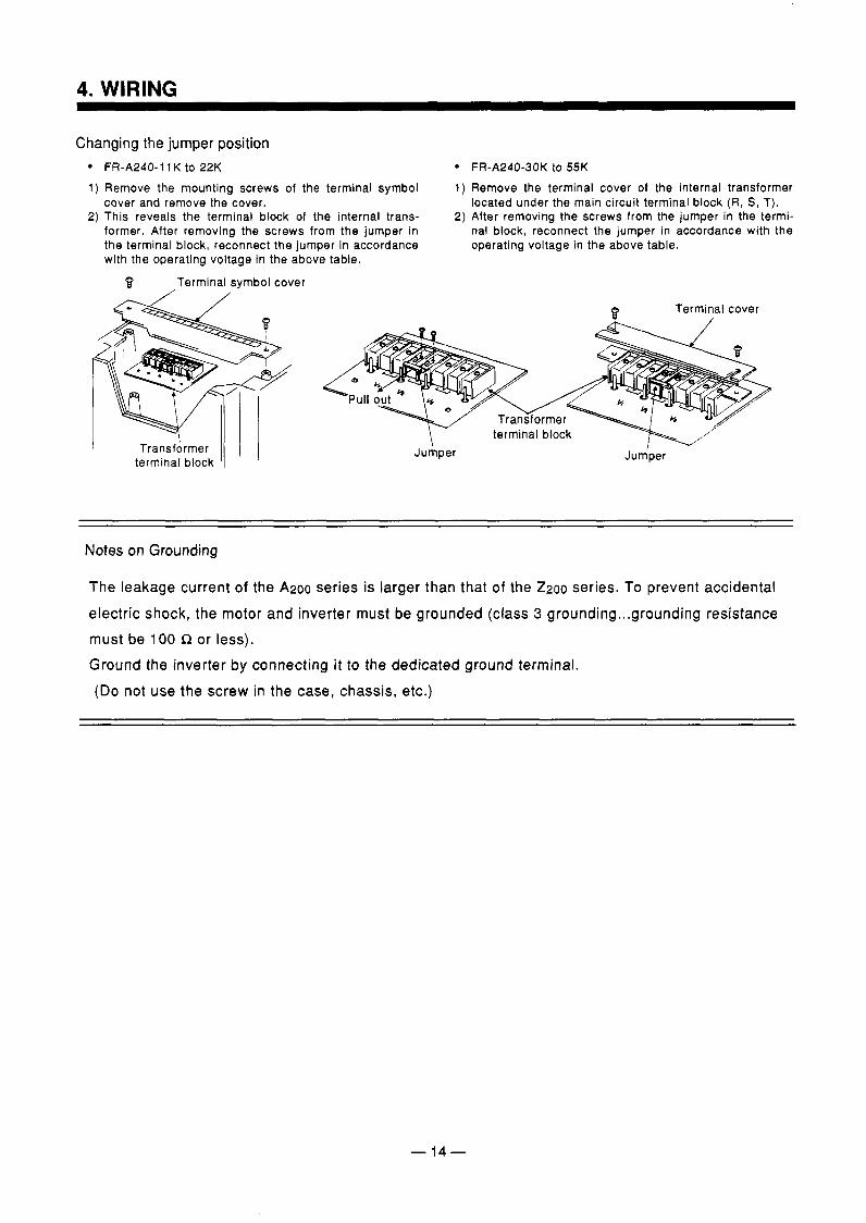
Changing the jumper position FR-A240-11 K to 22K FR-A240-30K to 55K
1) Remove the mounting screws of the terminal symbol 1) Remove the terminal cover of the internal transformer cover and remove the cover. located under the main circuit terminal block (R, S, T).
2) This reveals the terminal block of the internal trans- 2) After removing the screws from the jumper in the termi- former. After removing the screws from the jumper in nal block, reconnect the jumper in accordance with the the terminal block, reconnect the jumper in accordance operating voltage in the above table. with the operating voltage in the above table.
B Terminal symbol cover
Terminal cover
I Jumper I
Jumper I TransfArmer
terminal block
Notes on Grounding
The leakage current of the A200 series is larger than that of the 2200 series. To prevent accidental
electric shock, the motor and inverter must be grounded (class 3 grounding ...g rounding resistance must be 100 R or less). Ground the inverter by connecting i t to the dedicated ground terminal. (Do not use the screw in the case, chassis, etc.)
- 14-
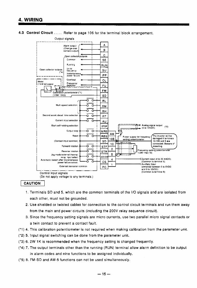
4.3 Control Circuit . . . . . Refer to page 106 for the terminal block arrangement.
I
I
Alarm output
contact output) (Change-over
Running
i ' i I
(1/3W 10Kn) I - 1 -
Multi-speed selection RM
Second accel./decel. time RT Current input selection
I Stan self-holding selection Analog signal output
i i i i L
Output stop
Reset
(Contact input common)
Forward rotation
Reverse rotation Jog modeiexternal thermal
Automatic restart after instantaneous relay input select
power failure select
Power supply for frequency
Current input (4 to 20 mADC) (Common is terminal 5)
External transistor common (switched between 0 to 5VDC
------------- and 0 to IOVDC) (Common is terminal 5) Control input signals
(Do not apply voltage to any terminals.)
1. Terminals SD and 5 , which are the common terminals of the I/O signals and are isolated from each other, must not be grounded.
2. Use shielded or twisted cables for connection to the control circuit terminals and run them away from the main and power circuits (including the 200V relay sequence circuit).
3. Since the frequency setting signals are micro currents, use two parallel micro signal contacts or
a twin contact to prevent a contact fault. (*1) 4. This calibration potentiometer is not required when making calibration from the parameter unit. ('2) 5. Input signal switching can be done from the parameter unit. (*3) 6. 2W 1 K is recommended when the frequency setting is changed frequently. (*4) 7. The output terminals other than the running (RUN) terminal allow alarm definition to be output
in alarm codes and nine functions to be assigned individually. (*5) 8. FM-SD and AM-5 functions can not be used simultaneously.
- 15-
4. WIRING
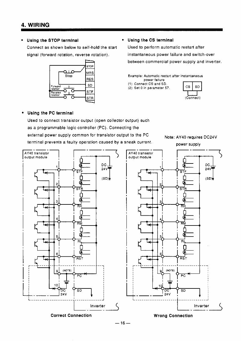
Using the STOP terminal Using the CS terminal Connect as shown below to self-hold the start Used to perform automatic restart after
signal (forward rotation, reverse rotation). instantaneous power failure and switch-over
RES
Forward I SD rotation
'Reverse I STF rotatlon
' - 0 STR
between commercial power supply and inverter.
Example: Automatic restart after instantaneous
(1) Connect CS and SD. (2) Set 0 in parameter 5 7 .
power failure
(Connect) U
Using the PC terminal Used to connect transistor output (open collector output) such as a programmable logic controller (PC). Connecting the
external power supply common for transistor output to the PC terminal prevents a faulty operation caused by a sneak current.
Note: AY40 requires DC24V power supply
r-
AY40 transistor output module
i i i i i i [ . _ 3 I
5. OPERATION
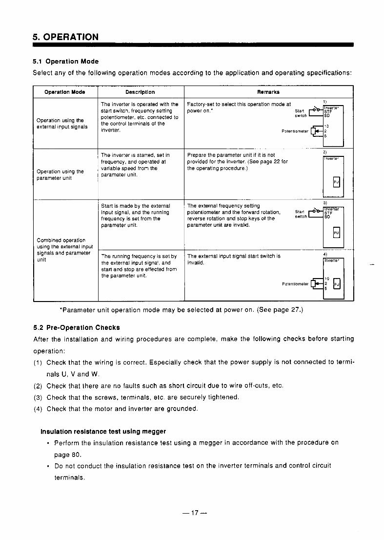
5.1 Operation Mode Select any of the following operation modes according to the application and operating specifications:
Operation Mode
Operation using the external input signals
Operation using the parameter unit
Combined operation using the external input signals and parameter unit
Descrlptlon
The inverter is operated with the start switch, frequency setting potentiometer, etc. connected to the control terminals of the inverter.
The inverter is started, set in frequency, and operated at variable speed from the parameter unit.
Start is made by the external input signal, and the running frequency is set from the parameter unit.
The running frequency is set by the external input signal, and start and stop are effected from the parameter unit.
Remarks
Factory-set to select this operation mode at power on.' nverter
switch
Potenbometer q: I Prepare the parameter unit if it is not provided for the inverter. (See page 22 for the operating procedure.)
The external frequency setting potentiometer and the forward rotation, %h 7; nverter reverse rotation and stop keys of the parameter unit are invalid.
3)
I U
The external input signal start switch is invalid.
Potentiometer
*Parameter unit operation mode may be selected at power on. (See page 27.)
5.2 Pre-Operation Checks After the installation and wiring procedures are complete, make the following checks before starting
operation: (1) Check that the wiring is correct. Especially check that the power supply is not connected to termi-
nals U, V and W. (2) Check that there are no faults such as short circuit due to wire off-cuts, etc. (3) Check that the screws, terminals, etc. are securely tightened. (4) Check that the motor and inverter are grounded.
Insulation resistance test using megger Perform the insulation resistance test using a megger in accordance with the procedure on page 80.
Do not conduct the insulation resistance test on the inverter terminals and control circuit terminals.
- 17-
5. OPERATION
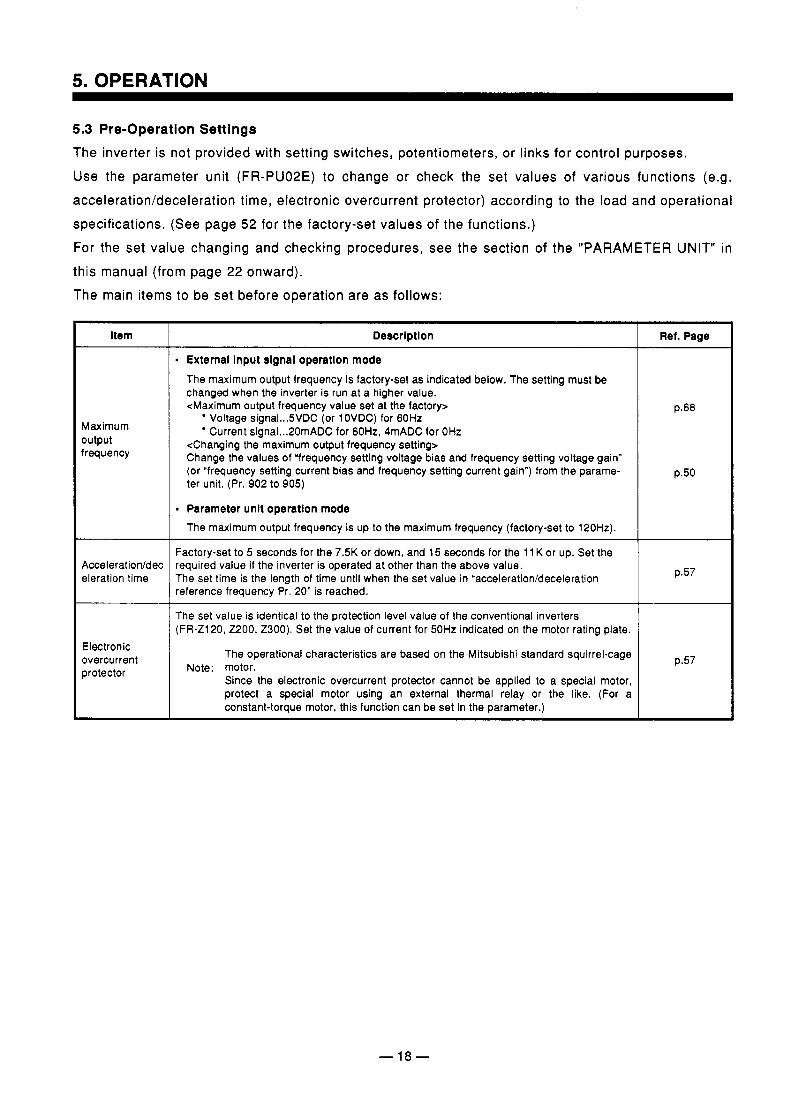
5.3 Pre-Operation Settings The inverter is not provided with setting switches, potentiometers, or links for control purposes. Use the parameter unit (FR-PU02E) to change or check the set values of various functions (e.g. acceleration/deceleration time, electronic overcurrent protector) according to the load and operational specifications. (See page 52 for the factory-set values of the functions.) For the set value changing and checking procedures, see the section of the "PARAMETER UNIT" in this manual (from page 22 onward). The main items to be set before operation are as follows:
item
Maximum output frequency
Acceleration/dec eleration time
Electronic overcurrent protector
Descrlptlon
D External Input signal operatlon mode The maximum output frequency is factory-set as indicated below. The setting must be changed when the inverter is run at a higher value. <Maximum output frequency value set at the factory>
Voltage signal ... 5VDC (or 10VDC) for 60Hz Current signal ... 20mADC for 60Hz, 4mADC for OHz
<Changing the maximum output frequency setting> Change the values of "frequency setting voltage bias and frequency setting voltage gain" (or "frequency setting current bias and frequency setting current gain") from the parame- ter unit. (Pr. 902 to 905)
Parameter unlt operation mode The maximum output frequency is up to the maximum frequency (factory-set to 120Hz).
Factory-set to 5 seconds for the 7.5K or down, and 15 seconds for the 11 K or up. Set the required value if the inverter is operated at other than the above value. The set time is the length of time until when the set value in "acceleration/deceleration reference frequency Pr. 20" is reached.
~~~ ~~
The set value is identical to the protection level value of the conventional inverters (FR-Z120, 2200, 2300). Set the value of current for 50Hz indicated on the motor rating plate.
The operational characteristics are based on the Mitsubishi standard squirrel-cage
Since the electronic overcurrent protector cannot be applied to a special motor, protect a special motor using an external thermal relay or the like. (For a constant-torque motor, this function can be set in the parameter.)
~ ~~~ ~
Note: motor.
Ret. Page
p.68
p.50
p.57
p.57
-18-
5. OPERATION
Descrlptlon
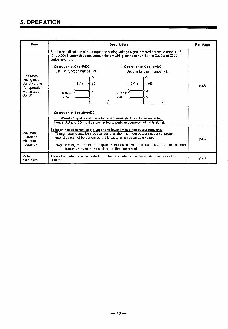
Set the specifications of the frequency setting voltage signal entered across terminals 2-5. (The A200 inverter does not contain the switching connector unlike the 2200 and 2300 series inverters.)
Operatlon at 0 to SVDC Operatlon at 0 to lOVDC Set 1 in function number 73. Set 0 in function number 73.
+5V 4 0 +1 ov 4 0 E
Oto5 I-12 0 to 10 VDC 5 VDC
Operatlon at 4 to 20mADC 4 to 20mADC input is only selected when terminals AU-SD are connected. Hence, AU and SD must be connected to perform operation with this signal.
To be only used to restrict the upper and lower limits of the output frequency. Though setting may be made at less than the maximum output frequency, proper operation cannot be performed if it is s e t to an unreasonable value.
Note: Setting the minimum frequency causes the motor to operate at the set minimum frequency by merely switching on the start signal.
4llows the meter to be calibrated from the parameter unit without using the calibration .esistor.
Ref. Page
p.68
p.56
p.48
- 19-
~
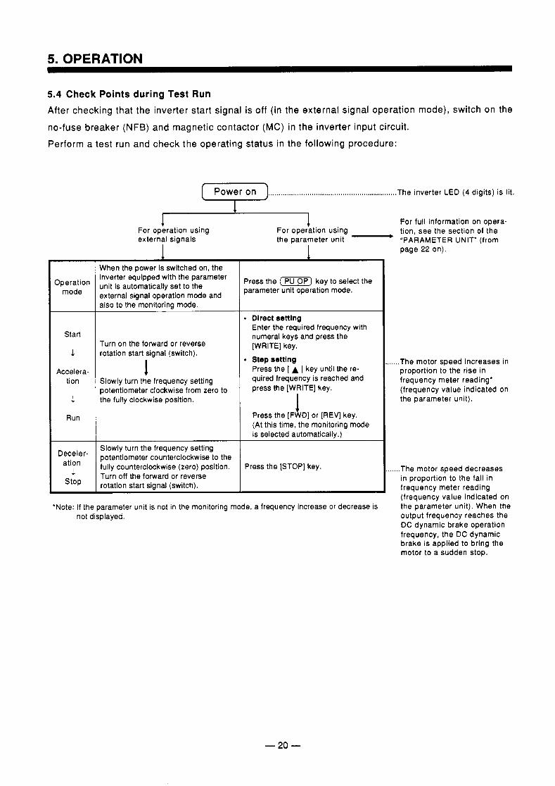
5.4 Check Points during Test Run After checking that the inverter start signal is off (in the external signal operation mode), switch on the
no-fuse breaker (NFB) and magnetic contactor (MC) in the inverter input circuit. Perform a test run and check the operating status in the following procedure:
D Power On .............................................................. The inverter LED ( 4 digits) is lit.
Operation mode
Start
I
Accelera- tion
I
Run
Deceler- ation
.1 stop
4 For operation using external signals
I
1 For full information on opera- For operation using tion, see the section of the the parameter unit - 'PARAMETER UNIT" (from
page 22 on)
When the power is switched on, the inverter equipped with the parametar unit is automatically set to the external signal operation mode and also to the monitoring mode.
~~
Turn on the forward or reverse rotation start signal (switch).
I slowly turn the frequency setting potentiometer clockwise from zero to the fully clockwise position.
Slowly turn the frequency setting potentiometer counterclockwise to the fully counterclockwise (zero) position. Turn off the forward or reverse rotation start signal (switch).
Press the (-1 key to select the parameter unit operation mode.
. Dlrect settlng Enter the required frequency with numeral keys and press the [WRITE] key.
Step settlng Press the [ A ] key until the re- quired frequency is reached and press the [WRITE] key.
Press the [F I Dl or [REV] key. (At this time, the monitoring mode is selected automatically.)
Press the [STOP] key.
'Note: If the parameter unit is not in the monitoring mode, a frequency increase or decrease is not displayed.
..... The motor speed increases in proportion to the rise in frequency meter reading' (frequency value indicated on the parameter unit).
..... The motor speed decreases in proportion to the fall in frequency meter reading (frequency value indicated on the parameter unit). When the output frequency reaches the DC dynamic brake operation frequency, the DC dynamic brake is applied to bring the motor to a sudden stop.
- 20 -
Check Points (1) Check that the direction of motor rotation is correct. (See page 11 for the wiring and rotation di-
.-
rection.) (2) Check that the motor is free from unusual noise or vibration. (3) Check that the frequency meter deflects smoothly. (4) Check that the “OL” code is not displayed on the parameter unit during acceleration or decelera-
tion. If the “OL” code is displayed:
Check that the load is not too large. Increase the acceleration/deceleration time.
Reduce the boost value.
Note (1) The inverter is not started up if the forward rotation (STF) and reverse rotation (STR) start
signals are turned on at the same time. The motor is decelerated to a stop if the above signals are switched on at the same time during operation.
(2) When ALARM is displayed on the inverter LED and the motor is coasted to a stop, make sure that the motor has stopped, then reset the inverter by switching the power off or using the reset terminal.
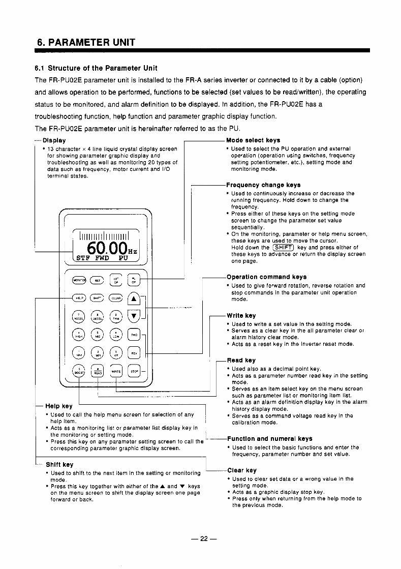
6.1 Structure of the Parameter Unit The FR-PU02E parameter unit is installed to the FR-A series inverter or connected to it by a cable (option) and allows operation to be performed, functions to be selected (set values to be read/written), the operating status to be monitored, and alarm definition to be displayed. In addition, the FR-PU02E has a troubleshooting function, help function and parameter graphic display function.
The FR-PU02E parameter unit is hereinafter referred to as the PU. -Display
13 character x 4 line liquid crystal display screen for showing parameter graphic display and troubleshooting as well as monitoring 20 types of data such as frequency, motor current and I/O terminal states.
I . I I
1 1 1 1 1 1 1 1 1 1 l 1 1 1 1 1 1 1 1 1 1
STF FWD PU I
I \ ’ I I f
II -I- C
Mode select keys
r-
Used to select the PU operation and external operation (operation using switches, frequency setting potentiometer, etc.), setting mode and monitoring mode.
-Frequency change keys Used to continuously increase or decrease the running frequency. Hold down to change the frequency. Press either of these keys on the setting mode screen to change the parameter set value sequentially. On the monitoring, parameter or help menu screen, these keys are used to move the cursor. Hold down the [m] key and press either of these keys to advance or return the display screen one page.
I r Operation command keys
Used to give forward rotation, reverse rotation and stop commands in the parameter unit operation mode.
-Write key Used to write a set value in the setting mode. Serves as a clear key in the all parameter clear or
Acts as a reset key in the inverter reset mode. alarm history clear mode.
-
-- -Read key
@ @ @ @Jj Used also as a decimal point key. Acts as a parameter number read key in the setting
< I I I mode.
L I Serves as an item select key on the menu screen such as parameter list or monitorina item list.
Help key ‘ I Used to call the help menu screen for selection of any
Acts as a monitoring list or parameter list display key in help item.
Acts as an alarm definition display key in the alarm
Serves as a command voltage read key in the history display mode.
calibration mode.
the monitoring or setting mode.
corresponding parameter graphic display screen. Used to select the basic functions and enter the Press this key on any parameter setting screen to call the /Function and numeral keys
frequency, parameter number and set value.
Shift key Used to shift to the next item in the setting or monitoring
Press this key together with either of the A and V keys setting mode.
Clear key mode. Used to clear set data or a wrong value in the
on the menu screen to shift the display screen one page Acts as a graphic display stop key. forward or back. Press only when returning from the help mode to
the previous mode.
- 22 -
6. PARAMETER UNIT
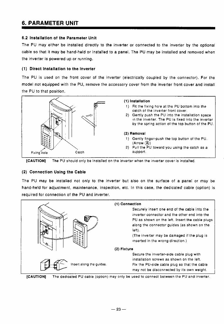
6.2 Installation of the Parameter Unit The PU may either be installed directly to the inverter or connected to the inverter by the optional
cable so that it may be hand-held or installed to a panel. The PU may be installed and removed when the inverter is powered up or running.
(1) Direct Installation to the Inverter
The PU is used on the front cover of the inverter (electrically coupled by the connector). For the model not equipped with the PU, remove the accessory cover from the inverter front cover and install the PU to that position.
\
I Fixing’hole
(1) Installation 1) Fit the f ixing hole at the PU bottom into the
2) Gently push the PU into the instal lat ion space catch of the inverter front cover.
in the inverter. The PU is f ixed into the inverter by the spring action of the top button of the PU.
I I \
Catch
(2) Removal 1 ) Gently f inger-push the top button of the PU.
2) Pul l the PU toward you using the catch as a (Arrow @)
support.
[CAUTION] The PU should only be instal led on the inverter when the inverter cover is instal led
(2) Connection Using the Cable
The PU may be installed not only to the inverter but also on the surface of a panel or may be hand-held for adjustment, maintenance, inspection, etc. In this case, the dedicated cable (option) is required for connection of the PU and inverter.
I
(1) Connection Securely insert one end of the cable into the inverter connector and the other end into the PU as shown on the left. Insert the cable plugs along the connector guides (as shown on the left). (The inverter may be damaged i f the plug is inserted in the wrong direct ion.)
(2) Fixture Secure the inverter-s ide cable p lug wi th instal lat ion screws as shown on the left . --e Insert along the guides. Fix the PU-side cable plug so that the cable may not be disconnected by its own weight.
[CAUTION] The dedicated PU cable (opt ion) may only be used to connect between the PU and inverter.
(3) Handling of the FR-ARWE parameter copy unit Like the FR-PU02E, the FR-ARWE fitted to the inverter (can also be connected by the cable) allows operation and functions to be set and operation status to be monitored. (The [ A ] and [ v] keys are different in function from those of the FR-PU02E.) The FR-ARWE also allows the inverter parameters set per application to be read in batches and easily copied to the other inverter.
(4) Use of the FR-PUOlE Parameter Unit Like the FR-PU02E, the FR-PUO1 E can be used by connection to the inverter by the cable (option). It
is to be understood that the FR-PUO1 E cannot be fitted directly to the inverter. Note the following:
1) When the power is on, the FR-PUOlE parameter unit and FR-PU02E parameter unit cannot be exchanged with each other. Before using the FR-PUOlE parameter unit, reset (or switch
off) the inverter once with the FR-PUO1 E and inverter connected by the cable. c The inverter recognizes the parameter unit type at the time of reset cancel or power-on
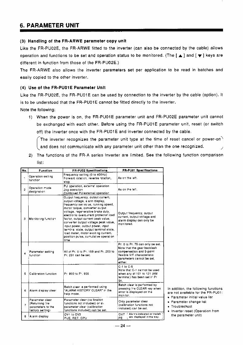
and does not communicate with any parameter unit other than the one recognized. 1 2) The functions of the FR-A series inverter are limited. See the following function comparison
list:
lo. FR-PUO1 Speclflcatlona FR-PUOZ Speclflcatlons Functlon Operation setting function
Operation mode designation
Frequency setting (0 to 400Hz) Forward rotation, reverse rotation, stop
As on the left.
motor torque, converter output frequency set value, running speed, output voltage, alarm display, Output frequency, output current, Combined PU/external operation
As on the left. Jog operation PU opration, external operation
voltage, regenerative brake duty, electronic overcurrent protector load
monitored, converter output voltage peak value,
current, output voltage and
input power, output power, input
Output frequency, output
3 alarm display can only be factor. output current peak value, Monitoring function
terminal state, output terminal state, load meter, motor exciting current, position pulse, cumulative operation
function Pr. 231 can be set.
Pr. 0 to Pr. 79 can only be set. Note that the gear backlash compensation and 5-point flexible VIF characteristic parameters cannot be set,
c - 1 to c - 5 Note that C-1 cannot be used
5 Calibratlon function when any of 101 to 121 (AM Pr. 900 to Pr. 905 terminal) has been set in Pr. 54. Batch clear is performed by
error is displayed on the monitor.
Only parameter clear (calibration functions not included) can be set.
Batch clear is performed using
help mode. 6
pressing the CLEAR key when "ALARM HISTORY CLEAR" in the Alarm display clear
Parameter clear
factory setting) parameter clear (calibration parameters to the functions not included) or all (Returning the , Parameter clear (calibration
functions included) can be set.
8 Alarm display OV1 toOV3 PUE, RET, CPU OVT ( Alarms indicated on theleft PE are displayed inthis way.
- 24 -
In add i t ion , the fo l low ing func t ions a re no t ava i l ab le f o r t he FR-PUO1 :
Parameter in i t ia l va lue l i s t Pa ramete r change l i s t T roub leshoo t Inver te r rese t (Opera t ion f rom the pa ramete r un i t )

6. PARAMETER UNIT
(5) Use of the FR-ZRWE Parameter Copy Unit The function of reading and copying parameters cannot be used. If the unit is operated incor-
rectly, the parameters of the inverter to which the parameters have been copied may be corrupted and normal operation not performed. The other functions can be used as in the FR-PUOlE.
- 25 -
.- . -
6. PARAMETER UNIT
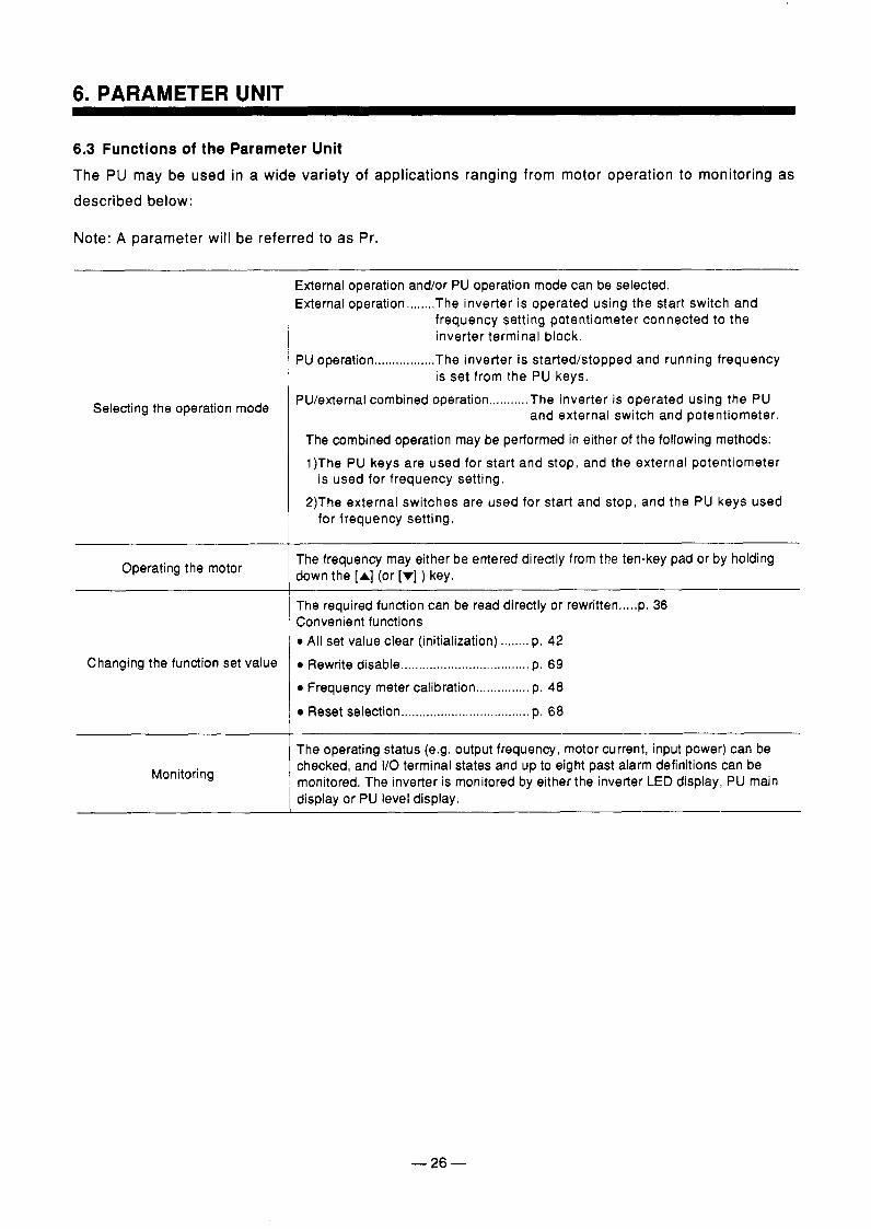
6.3 Functions of the Parameter Unit The PU may be used in a wide variety of applications ranging from motor operation to monitoring as described below:
Note: A parameter will be referred to as Pr.
Selecting the operation mode
Operating the motor
Changing the function set value
i Monitoring
I
External operation and/or PU operation mode can be selected. External operation ........ The inverter is operated using the start switch and
frequency setting potentiometer connected to the inverter terminal block.
PU operation ................. The inverter is startedktopped and running frequency
PU/external combined operation ........... The inverter is operated using the PU
The combined operation may be performed in either of the following methods: 1)The PU keys are used for start and stop, and the external potentiometer
2)The external switches are used for start and stop, and the PU keys used
is set from the PU keys.
and external switch and potentiometer.
is used for frequency setting.
for frequency setting.
The frequency may either be entered directly from the ten-key pad or by holding down the [A] (or [r] ) key.
The required function can be read directly or rewritten .....p. 36 Convenient functions 0 All set value clear (initialization) ........ p. 42 0 Rewrite disable .................................... p. 69 0 Frequency meter calibration ............... p. 48
Reset selection .................................... p. 68
The operating status (e.g. output frequency, motor current, input power) can be checked, and I/O terminal states and up to eight past alarm definitions can be monitored. The inverter is monitored by either the inverter LED display, PU main display or PU level display.
- 26 -
6. PARAMETER UNIT
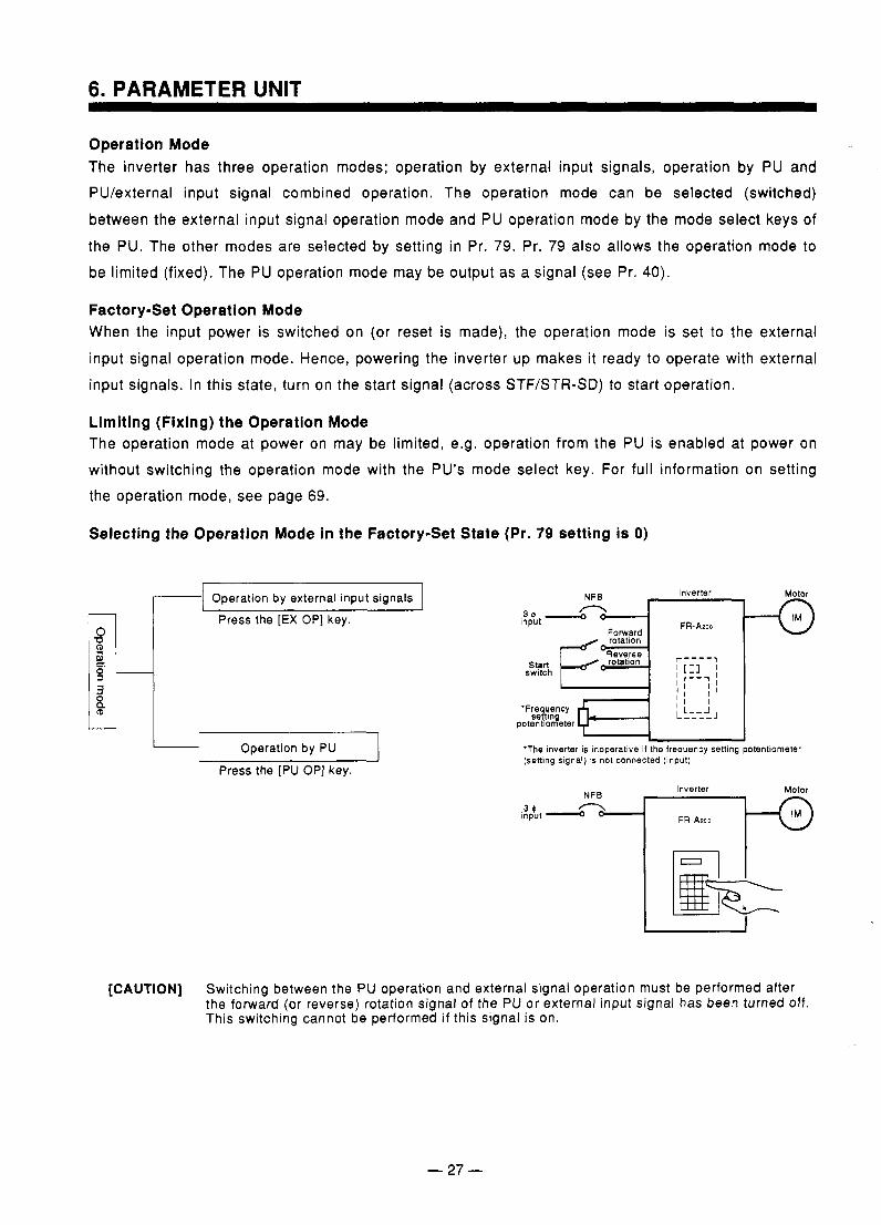
Operation Mode The inverter has three operation modes; operation by external input signals, operation by PU and PU/external input signal combined operation. The operation mode can be selected (switched)
between the external input signal operation mode and PU operation mode by the mode select keys of the PU. The other modes are selected by setting in Pr. 79. Pr. 79 also allows the operation mode to be limited (fixed). The PU operation mode may be output as a signal (see Pr. 40).
Factory-Set Operation Mode When the input power is switched on (or reset is made), the operation mode is set to the external input signal operation mode. Hence, powering the inverter up makes it ready to operate with external input signals. In this state, turn on the start signal (across STF/STR-SD) to start operation.
Limiting (Fixing) the Operation Mode The operation mode at power on may be limited, e.g. operation from the PU is enabled at power on without switching the operation mode with the PU's mode select key. For full information on setting the operation mode, see page 69.
Selecting the Operation Mode in the Factory-Set State (Pr. 79 setting is 0)
L 1 (D
-1 Operation by external input signals I Press the [EX OP] key.
-1 Operation by PU I Press the [PU OP] key.
'Frequency settlng +-u - - - - J
'The Inverter is inoperatlve I f the frequency setting potentiometer (setting signal) IS not connected (Input)
potentlometer
Inverter Motor
Input 3 0
[CAUTION] Switching between the PU operation and external signal operation must be performed after the forward (or reverse) rotation signal of the PU or external input signal has been turned off. This switching cannot be performed if this signal is on.
Running the Motor from the Parameter Unit
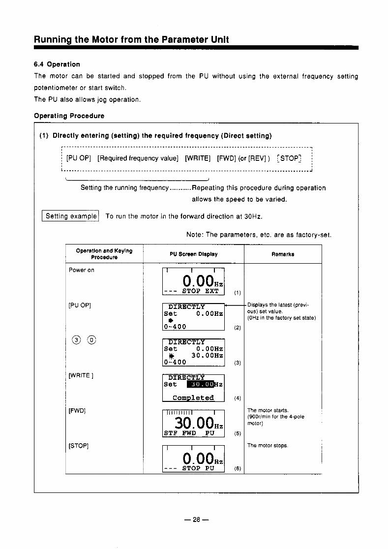
6.4 Operation The motor can be started and stopped from the PU without using the external frequency setting potentiometer or start switch. The PU also allows jog operation.
Operating Procedure
Setting the running frequency ............ Repeating this procedure during operation allows the speed to be varied.
-1 To run the motor in the forward direction at 30Hz.
Note: The parameters, etc. are as factory-set.
Operation and Keylng Procedure
Power on
[PU OP]
[WRITE ]
[STOP]
PU Screen Display
I DIRECTLY- 0. OOHz
0-400
DIRECTLY S e t 0 . OOHz
I C o m p l e t e d I I 1 1 1 1 1 1 1 1 1 1 1 I I
I 30. OOmI I S T F FWD PU I
I _ - - STOP Pu I
Remarks
Displays the latest (previ- ous) set value. (OH2 in the factory set state)
The motor starts. (900r/min for the 4-pole motor)
The motor stops.
I
- 28 -
Runnina the Motor from the Parameter Unit
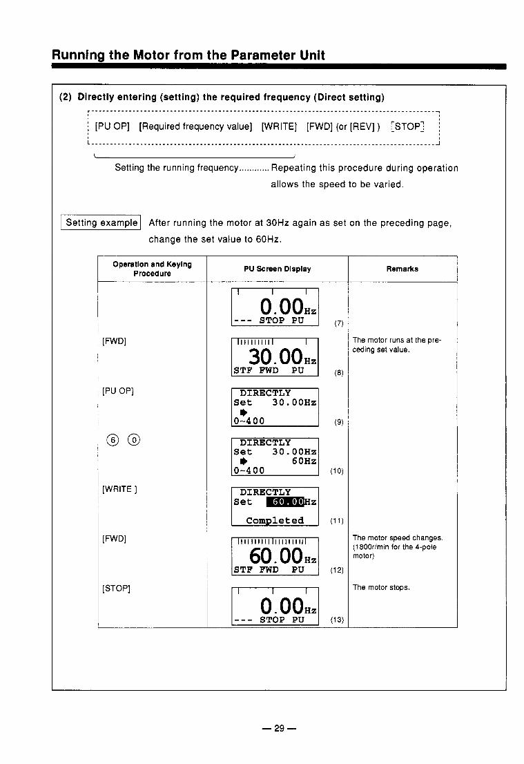
Setting the running frequency ............ Repeating this procedure during operation allows the speed to be varied.
1 Setting example] After running the motor at 30Hz again as set on the preceding page,
change the set value to 60Hz.
Operatlon and Keylng Procedure
[FWD1
[PU OP]
@ @
[WRITE ]
[FWD1
[STOP]
PU Screen Dlsplay
I I I I I I I I I I I I I 1
I 30.00HzI LSTF FWD PU I
0-400
DIRECTLY
0-400
I Completed I I 1 1 1 1 1 1 1 1 1 1 1 1 1 1 1 1 1 1 1 1 1 I I 60. OOmI ISTF FWD PU I
I O . O O H z 1 I _ _ _ STOP PU I
Remarks
The motor runs at the pre- ceding set value.
The motor speed changes. (1800r/min for the 4-pole motor)
The motor stops.
- 29 -
.
Runnina the Motor from the Parameter Unit
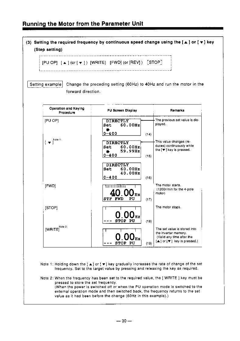
(3) Setting the required frequency by continuous speed change using the [A ] or [ v] key (Step setting)
j [PU OP] [ A ] (or [ v ] ) [WRITE] [FWD] (or [REV] ) [STOP: j
Setting example1 Change the preceding setting (60Hz) to 40Hz and run the motor forward direction.
Operation and Keying Procedure
[PU OP]
[ V rote ’:
[FWD1
[ S T 0 PI
[WRITE] Note 2.
PU Screen Dlsplay ~~
0-400
0-400
4 0 . OOHz
STF FWD PU
STOP PU
STOP PU
in the
Remarks
The previous set value is dis- played.
This value changes (re- duces) continuously while the [v] key is pressed.
The motor starts. (1 200rlmin for the 4-pole
motor)
The motor stops.
The set value is stored into the inverter memory. (Valid any time after the [A] or [v] key is pressed.)
Note 1 : Hold ing down the [ A ] or [ v ] key gradually increases the rate of change of the set frequency. Set to the target value by pressing and releasing the key as required.
Note 2: When the f requency has been set to the required value, the [ WRITE ] key must be pressed to store the set frequency. (When the power is switched off or when the PU operat ion mode is switched to the external operat ion mode and then swi tched back, the f requency re turns to the set value as i t had been before the change (60Hz in this example).)
- 30 -
Runninzt the Motor from the Parameter Unit
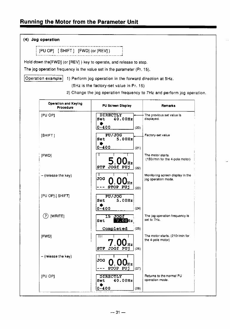
(4) Jog operation ,---------------------------------------------------~ i [PU OP] [ SHIFT] [FWD] (or [REV] ) L . - - - . - - . - - . . - - - - - - - - - - - - - - - - - - - - - - - - - - - - - - - - - - - - - - - ~
Hold down the[FWD] (or [REV] ) key to operate, and release to stop.
The jog operation frequency is the value set in the parameter (Pr. 15).
Operation example1 1) Perform jog operation in the forward direction at 5Hz. (5HZ is the factory-set value in Pr. 15)
2) Change the jog operation frequency to 7Hz and perform jog operation.
Operation and Keying Procedure
[PU OP]
- (release the key)
[PU OP] [ SHIFT]
@ [WRITE]
[FWD1
- (release the key)
[PU OP]
PU Screen Display
5 . OOHz
0-4 0 0
I 5. O O H J
ISTF J O G f PU j I (26) -
Remarks
The previous set value is displayed.
Factory-set value
The motor starts. (1 50r/min for the 4-pole motor)
Monitoring Screen display in the j o g operation mode.
The jog operation frequency is set to 7Hz.
The motor starts. (2lOrlmin for the 4-pole motor)
Returns to the normal PU operation mode.
- 31 -
. . . . . . . . . . .
Chanaina the Monitor Screen
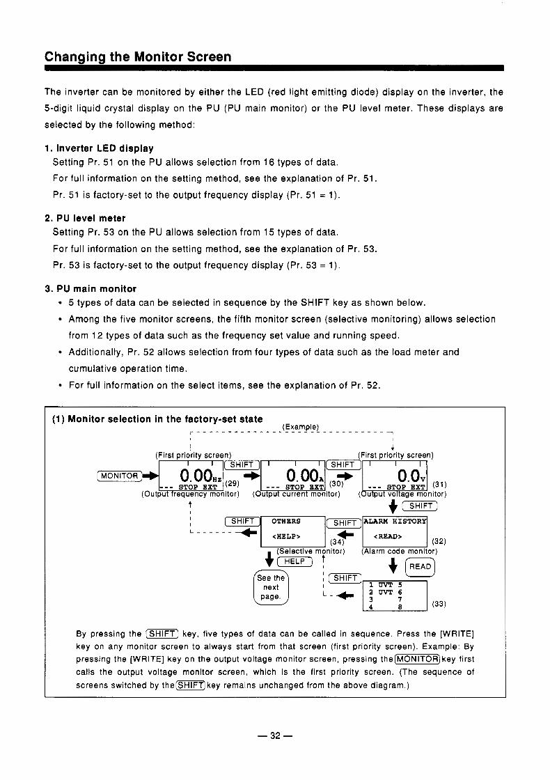
The inverter can be monitored by either the LED (red light emitting diode) display on the inverter, the 5-digit liquid crystal display on the PU (PU main monitor) or the PU level meter. These displays are selected by the following method:
1. Inverter LED display Setting Pr. 51 on the PU allows selection from 16 types of data. For full information on the setting method, see the explanation of Pr. 51.
Pr. 51 is factory-set to the output frequency display (Pr. 51 = 1).
2. PU level meter Setting Pr. 53 on the PU allows selection from 15 types of data. For full information on the setting method, see the explanation of Pr. 53. Pr. 53 is factory-set to the output frequency display (Pr. 53 = 1).
3. PU main monitor 5 types of data can be selected in sequence by the SHIFT key as shown below. Among the five monitor screens, the fifth monitor screen (selective monitoring) allows selection from 12 types of data such as the frequency set value and running speed. Additionally, Pr. 52 allows selection from four types of data such as the load meter and cumulative operation time. For full information on the select items, see the explanation of Pr. 52.
(1) Monitor selection in the factory-set state (Exa-mple) r - - - - - - - - - - - - - - - _ - _ _ _ _ - _ - _ - _ _ _ 1
I I
I 4 (First priority screen) (First priority screen)
I t + (sHIFT) I
I n n v t I
By pressing the (m) key, f ive types of data can be cal led in sequence. Press the [WRITE] key on any monitor screen to always start from that screen (f i rst priori ty screen). Example: By pressing the [WRITE] key on the output vol tage monitor screen, pressing t h e [ m R ] k e y first cal ls the output voltage monitor screen, which is the f i rst priori ty screen. (The sequence of sc reens sw i tched by the [m]key remains unchanged f rom the above d iagram.)
- 32 -
Changing the Monitor Screen
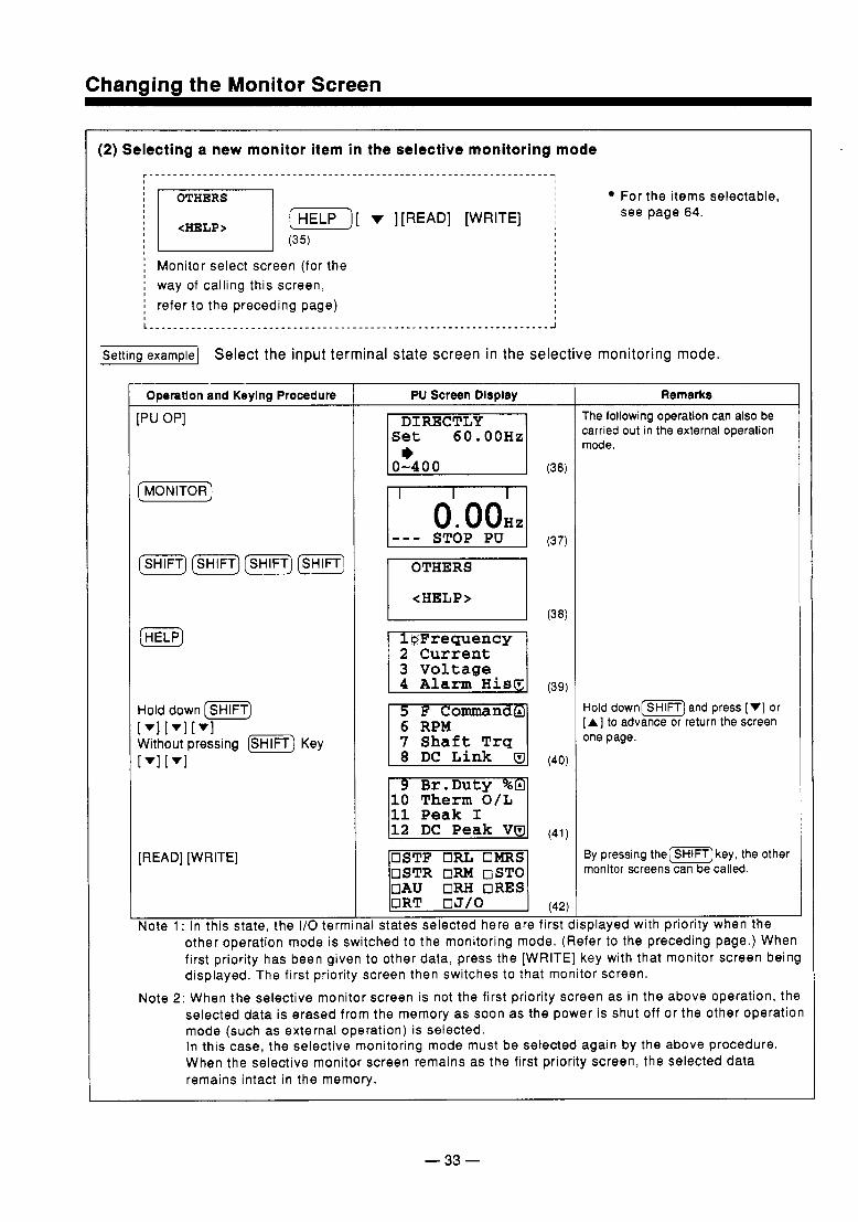
(2) Selecting a new monitor item in the selective monitoring mode
I I OTHERS For the i tems selectable,
[ v ][READ] [WRITE] j see page 64.
I I
-1 Select the input terminal state screen in the selective monitoring mode.
I
Operatlon and Keying Procedure
;Pu OP]
(MONITOR)
Hold down (SHIFT)
Without pressing I . ) Key [Vl[Vl[Vl
[READ] [WRITE]
Note 1 : In this state, the I/O term
PU Screen Display
(36)
I I O . O O H , /
I
- - - STOP PU I (37)
<HELP>
10 T h e r m O / L 11 P e a k I
/ O R T I (42)
USTF ORL UMRS USTR OM OSTO OAU ORH ORES
al states selected here are f i rst (
Remarks The following operation can also be carried out in the external operation mode.
Hold d o w n [ m ] and press [ V] or [A] to advance or return the screen one page.
By pressing t h e ( m ) key, the other monitor screens can be called.
;played with priority when the other operat ion mode is switched to the monitor ing mode. (Refer to the preceding page.) When first priority has been given to other data, press the [WRITE] key with that monitor screen being displayed. The f i rst priori ty screen then switches to that monitor screen.
Note 2: When the selective monitor screen is not the f irst priority screen as in the above operation, the selected data is erased f rom the memory as soon as the power is shut of f or the other operation mode (such as external operation) is selected. In this case, the select ive monitoring mode must be selected again by the above procedure. When the select ive monitor screen remains as the f i rst priori ty screen, the selected data remains intact in the memory.
- 33 -
Chanaina the Monitor Screen
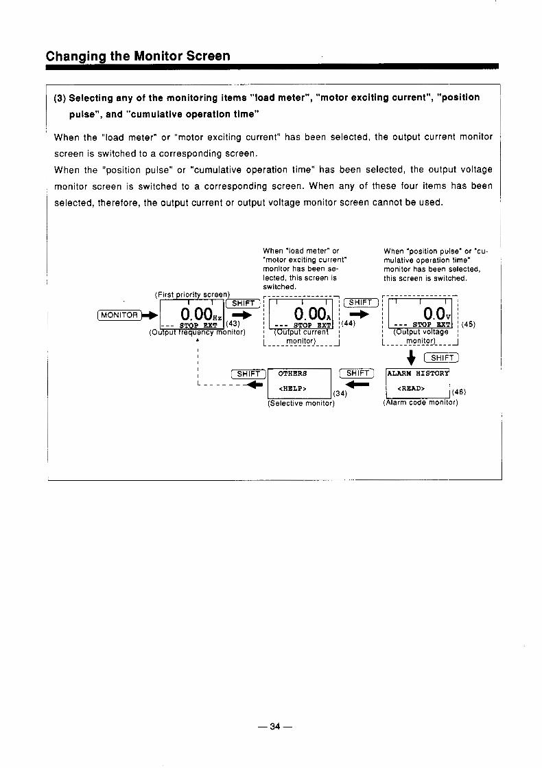
(3) Selecting any of the monitoring items "load meter", "motor exciting current", "position pulse", and "cumulative operation time"
When the "load meter" or "motor exciting current" has been selected, the output current monitor screen is switched to a corresponding screen. When the "position pulse" or "cumulative operation time" has been selected, the output voltage monitor screen is switched to a corresponding screen. When any of these four items has been selected, therefore, the output current or output voltage monitor screen cannot be used.
I 1
When "load meter" or When "position pulse" or "cu- "motor exciting current" mulative operation time" monitor has been se- monitor has been selected, lected, this screen is this screen is switched. switched.
[ M O N I T O R ~
t L - - -_ RO_!i!O_r_--- - _I L _ _ _ _ _ !?!El) _ _ _ _ J I I I
I I
(Selective monitor) (Alarm code monitor)
- 34 -
Channinn the Monitor Screen
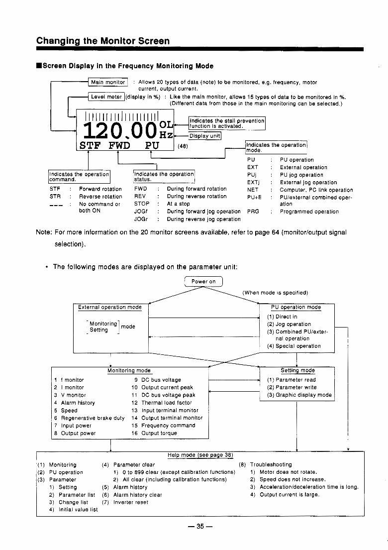
.Screen Display in the Frequency Monitoring Mode
-1 Main monitor I : Allows 20 types of data (note) to be monitored, e.g. frequency, motor current, output current.
Level meter (display in 40) : Like the main monitor, allows 15 types of data to be monitored in %. (Different data from those in the main monitoring can be selected.) - I I I I I I I I I I l l I I I I 1 l l 1 1
* unit] ! E D i s p l a y 12 0 O O function is activated.
Indicates the stall prevention
STF FWD PU . (48) mode. Indicates the operation
PU : PU operation e3 EXT : External operation PUj : PU jog operation EXTj : External jog operation command.
Indicates the operation Indicates the operation
STF : Forward rotation FWD : During forward rotation NET : Computer, PC link operation STR : Reverse rotation REV : During reverse rotation PU+E : PU/external combined oper- _ _ _ : No command or STOP : At a stop
status.
both ON JOGf : During forward jog operation PRG : Programmed operation JOGr : During reverse jog operation
ation
Note: For more information on the 20 monitor screens available, refer to page 64 (monitor/output signal
. selection).
The following modes are displayed on the parameter unit:
Power on
mode is specified)
External operation mode PU operation mode (1) Direct in (2) Jog operation (3) Combined PU/exter-
-
nal operation (4 ) Special operation
I(
I I
I J
1 J Monitoring mode
1 f monitor 9 DC bus voltage 2 I monitor 10 Output current peak 3 V monitor 11 DC bus voltage peak 4 Alarm history 12 Thermal load factor 5 Speed 13 Input terminal monitor 6 Regenerative brake duty 14 Output terminal monitor 7 Input power 15 Frequency command 8 Output power 16 Output torque
I Setting mode (1 ) Parameter read (2) Parameter write (3) Graphic display mode
L 1 Help mode (see page 38)
(1) Monitoring (4) Parameter clear (8) Troubleshooting (2) PU operation 1) 0 to 899 clear (except calibration functions) 1) Motor does not rotate. (3) Parameter 2) All clear (including calibration functions) 2) Speed does not increase.
1) Setting (5) Alarm history 2) Parameter list (6) Alarm history clear 3) Change list (7 ) Inverter reset 4) initial value list
3) Acceleration/deceleration time is long. 4) Output current is large.
- 35 -
.-- __. . . . . . . . .
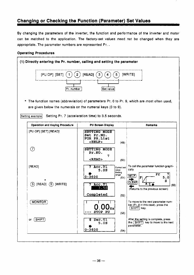
Changing or Checking the Function (Parameter) Set Values
By changing the parameters of the inverter, the function and performance of the inverter and motor can be matched to the application. The factory-set values need not be changed when they are appropriate. The parameter numbers are represented Pr. .
Operating Procedures
(1) Directly entering the Pr. number, calling and setting the parameter
i [PU OP] [SET] @ @ [READ] @ @ @ [WRITE]
IPr. number 1 [Set value]
* The function names (abbreviation) of parameters Pr. 0 to Pr. 9, which are most often used, are given below the numerals on the numeral keys (0 to 9).
Setting Pr. 7 (acceleration time) to 3.5 seconds.
Operation and Keylng Procedure
[PU OP] [SET] [READ]
[READ]
* @ [READ] @ [WRITE]
f MONITOR^
or [ M I
PU Screen Dlsplay
Set Pr. NO. FOR PR.Liet
1 (50) SETTING MODE Pr.NO.
<READ>
(51)
I o . o o € i z l
i,505 (54)
8 Dec.T1
0-3600
Remarks
To call the parameter function graphi- cally
1 Pr 71
(Returns to the previous screen)
To move to the next parameter num- ber Pr. 8 in this case), press the (h] key.
After the setting is complete, press the (m) key to move to the next parameter.
-36-
Changing or Checking the Function (Parameter) Set Values
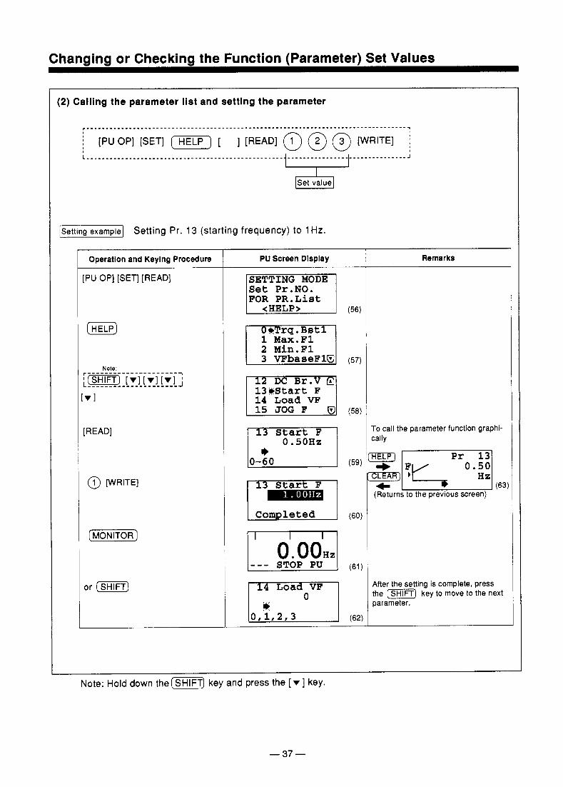
(2) Calling the parameter list and setting the parameter
[Setting example1 Setting Pr. 13 (starting frequency) to 1 Hz.
Operatlon and Keylng Procedure t
:PU OP] [SET] [READ]
[HELP)
Note:
VI
[READ]
@ [WRITE]
(hnONITOR)
or ( m j
PU Screen Dlsplay
1 (56)
SETTING MODE Set Pr.NO. FOR PR.List
<HELP>
1 Max.F1 2 Min.Fl
13Wtart F 14 Load vp
Start F
(59)
Start F
(60)
Remarks
To call the parameter function graphi- cally
HELP)
(63) (Returns to the previous screen)
After the setting is complete, press the (SHlFTj key to move to the next parameter.
Note: Hold down the (WT) key and press the [ v ] key.
- 37 -
..--.-_. * . .. .. .-
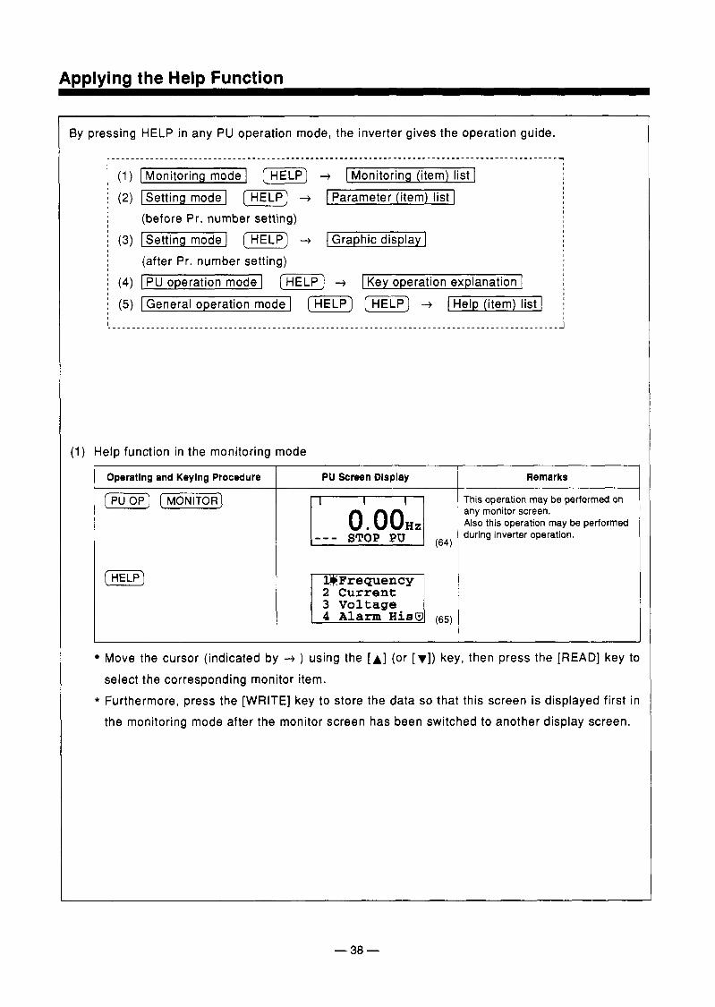
By pressing HELP in any PU operation mode, the inverter gives the operation guide.
i (1) [Monitoring mode I [m] + I Monitoring (item) list 1 i (2) [Setting mode I [m) + [Parameter (item) list 1
~ (3) [Setting mode I [m) + I Graphic display] (before Pr. number setting)
(after Pr. number setting) i (4) [ PU operation mode I (HELP) + I Key operation explanation 1 i (5) [General operation model (m) (m) + 1 Help (item) list I j
(1) Help function in the monitoring mode
Operatlng and Keylng Procedure PU Screen Dlsplay
( p u ) [MoNIToR_)
(HELP) 3 Voltage
Remarks 7 This operation may be performed on any monitor screen. Also this operation may be performed during inverter operation.
Move the cursor (indicated by ) using the [A] (or [ r]) key, then press the [READ] key to select the corresponding monitor item.
* Furthermore, press the [WRITE] key to store the data so that this screen is displayed first in the monitoring mode after the monitor screen has been switched to another display screen.
- 38 -
ADDlvina the HelD Function
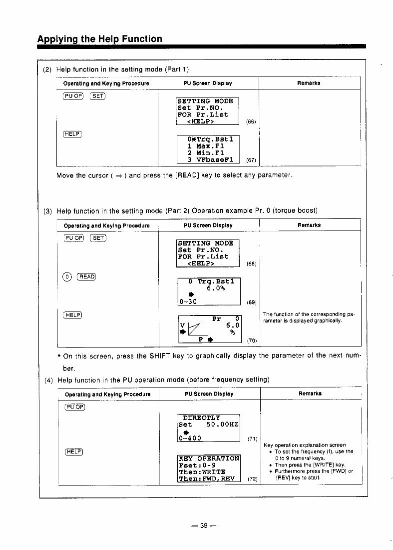
(2) Help function in the setting mode (Part 1)
Operating and Keying Procedure PU Screen Display
( p u ) @g
(HELP) (66)
SETTING MODE Set Pr.NO. FOR Pr.List
<HELP>
1 Max.F1 2 Min.Fl
Remarks
Move the cursor ( + ) and press the [READ] key to select any parameter.
(3) Help function in the setting mode (Part 2) Operation example Pr. 0 (torque boost)
I Operatlng and Keying Procedure
( p u ) ISET) PU Screen Dlspiay
SETTING MODE Set Pr .NO. FOR Pr.List
<HELP>
0 Trg.Bst1 6.0%
(69)
Remarks
The function of the corresponding pa- rameter is displayed graphically.
On this screen, press the SHIFT key to graphically display the parameter of the next num
ber. (4) Help function in the PU operation mode (before frequency setting)
I Operating and Keying Procedure I PU Screen Dlspiay
( p u )
(71)
Remarks
Key operation explanation Screen To set the frequency (f), use the
Then press the [WRITE] key. Furthermore press the [FWD] or
0 to 9 numeral keys.
[REV] key to start.
- 39 -
ADDlvina the HelD Function
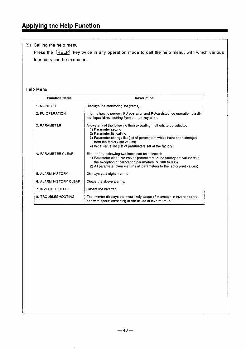
( 5 ) Calling the help menu Press the (HELP) key twice in any operation mode to call the help menu, with which various functions can be executed.
Help Menu
Function Name
1. MONITOR
2. PU OPERATION
3. PARAMETER
4. PARAMETER CLEAR
5. ALARM HISTORY
6. ALARM HISTORY CLEAR
7. INVERTER RESET
8. TROUBLESHOOTING
Descrlptlon
Displays the monitoring list (items).
Informs how to perform PU operation and PU-assisted jog operation via di- rect input (direct setting from the ten-key pad).
Allows any of the following item executing methods to be selected: 1) Parameter setting 2) Parameter list calling 3) Parameter change list (list of parameters which have been changed
4) Initial value list (list of parameters set at the factory) from the factory-set values)
Either of the following two items can be selected: 1) Parameter clear (returns all parameters to the factory-set values with
2) All parameter clear (returns all parameters to the factory-set values) the exception of calibration parameters Pr. 900 to 905)
Displays past eight alarms.
Clears the above alarms.
Resets the inverter.
The inverter displays the most likely cause of mismatch in inverter opera- tion with operation/setting or the cause of inverter fault.
- 40 -
Amlvincl the HelD Function
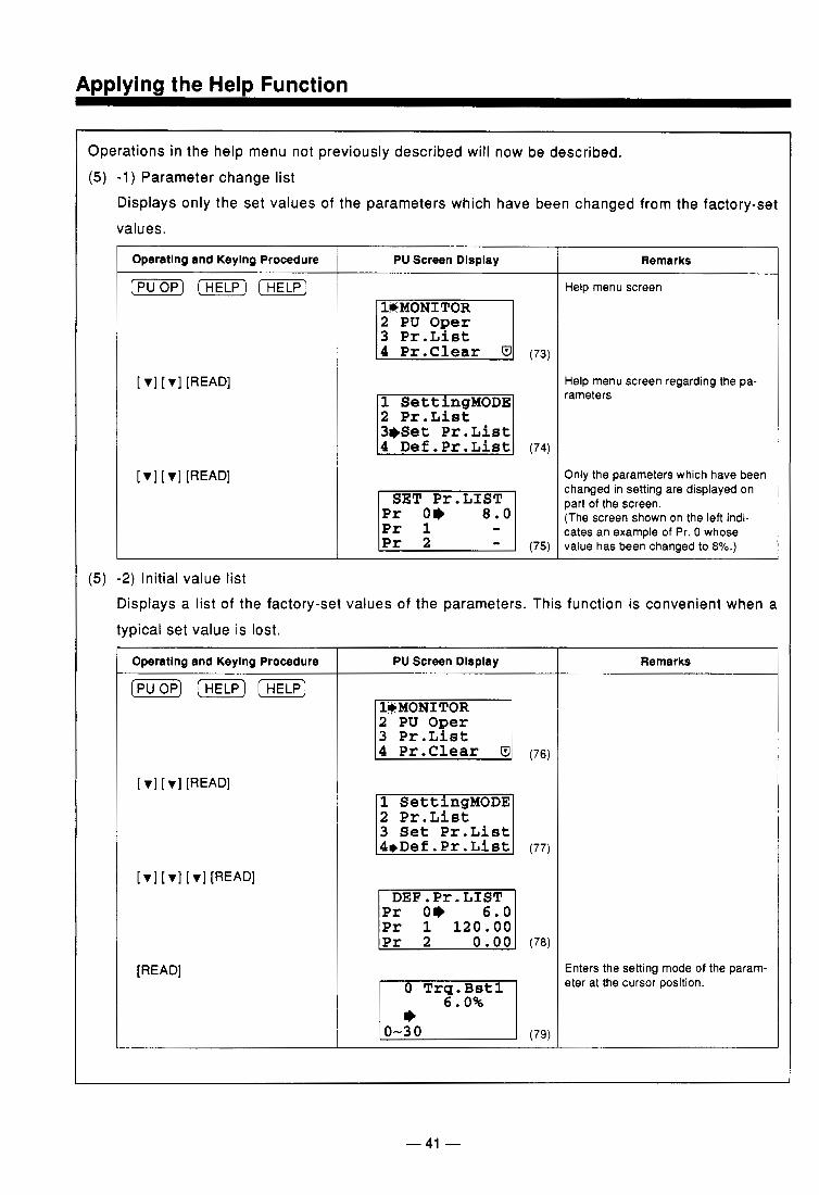
Operations in the help menu not previously described will now be described. (5) -1) Parameter change list
Displays only the set values of the parameters which have been changed from the factory-se,
values.
Operating and Keylng Procedure
( p u ) (HELP) ( H E L P )
PU Screen Display
2 PU Oger 3 Pr.List
2 Pr.List 31)Set Pr. List
Remarks
Help menu screen
Help menu screen regarding the pa- rameters
Only the parameters which have been changed in setting are displayed on part of the screen. (The screen shown on the left indi- cates an example of Pr. 0 whose value has been changed to 8%.)
(5) -2) Initial value list Displays a list of the factory-set values of the parameters. This function is convenient when a typical set value is lost.
Operating and Keying Procedure I PU Screen Display
[READ]
2 PU Oger 3 Pr.List
2 Pr.List 3 Set Pr.List
DEF.Pr.LIST
0 Trg.Bst1 6.0%
f Remarks
Enters the setting mode of the param- eter at the cursor position.
- 41 -
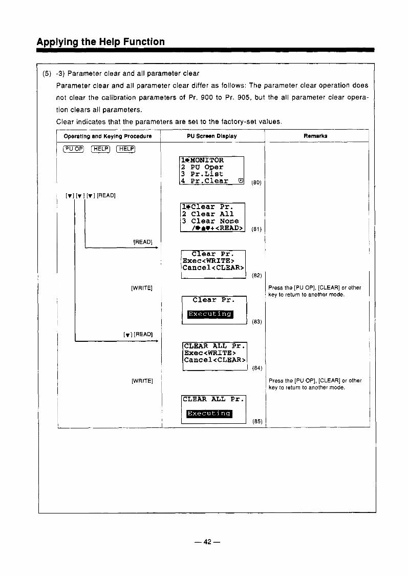
(5) -3) Parameter clear and all parameter clear Parameter clear and all parameter clear differ as follows: The parameter clear operation does not clear the calibration parameters of Pr. 900 to Pr. 905, but the all parameter clear opera- tion clears all parameters. Clear indicates that the parameters are set to the factory-set values.
Operating and Keylng Procedure
I c
[WRITE]
[WRITE]
PU Screen Display
1#MONITOR 2 PU Oper
4 Pr . Clear (80)
3 Clear None
Exec<WRITE> Cancel<CLEAR>
CLEAR ALL Pr. Exec<WRITE> Cancel<CLEAR>
L = J ,e=\
CLEAR ALL Pr.
Remarks
Press the [PU OP], [CLEAR] or other key to return to another mode.
Press the [PU OP], [CLEAR] or other key to return to another mode.
-42-
Applying the Help Function
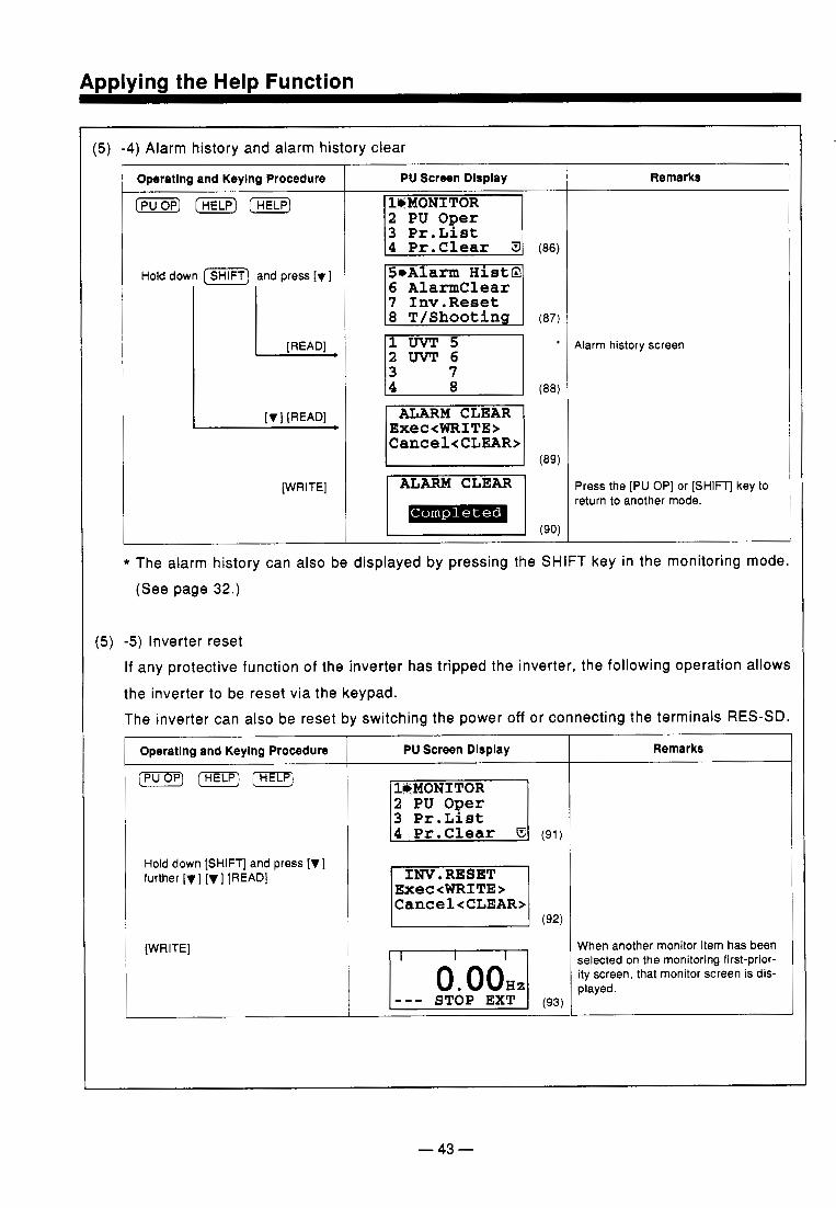
(5) -4) Alarm history and alarm history clear
Operatlng and Keylng Procedure
( o p ] (HELP)
Hold down (m] and press [v I
[WRITE]
PU Screen Dlsplay
(88)
Remarks
Alarm history screen
Press the [PU OP] or [ S H I V key to return to another mode.
* The alarm history can also be displayed by pressing the SHIFT key in the monitoring mode (See page 32.)
(5) -5) Inverter reset If any protective function of the inverter has tripped the inverter, the following operation allow the inverter to be reset via the keypad. The inverter can also be reset by switching the power off or connecting the terminals RES-SD
Operatlng and Keylng Procedure
Hold down [SHIFT] and press [V 1 further [v 1 [v I [READ]
[WRITE]
I
PU Screen Dlsplay
2 PU Oger 3 Pr.List
INV. RESET Exec<WRITE> Cancel<CLEAR>
I 0. O O H z l - - - STOP EXT I (93) I
Remarks _ _ _ ~
When another monitor item has been selected on the monitoring first-prior- ity screen, that monitor screen is dis- played.
- 43 -
........... - -. . . . . . . . . . . . . . . .
Applying the Help Function
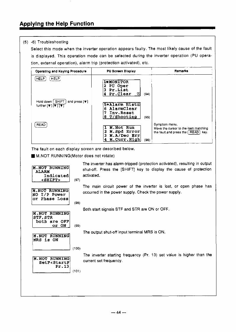
( 5 ) -6) Troubleshooting Select this mode when the inverter operation appears faulty. The most likely cause of the fault is displayed. This operation mode can be selected during the inverter operation (PU opera- tion, external operation), alarm trip (protection activated), etc.
Operating and Keying Procedure
Hold down [ SHITT] and press [VI further [v 1 lv 1 lv I
PU Screen Display
2 PU Oger 3 Pr.List
6 Alarmclear 7 1nv.Reset
2 M.Spd Error
Remarks
Symptom menu. Move the cursor to the item matching the fault and press the (READ) key.
The fault on each display screen are described below. M.NOT RUNNING(Motor does not rotate)
The inverter has alarm-tripped (protection activated), resulting in output shut-off. Press the [SHIFT] key to display the cause of protection M.NOT RUNNING
Indicated <SHIFT>
The main circuit power of the inverter is lost, or open phase has occurred in the power supply. Check the power supply. M.NOT RUNNING
lor Phase Loss1 (ge)
Both start signals STF and STR are ON or OFF. 1M. NOT RUNNING] STF, STR both are OFF
The output shut-off input terminal MRS is ON.
MRS is ON
The inverter starting frequency (Pr. 13) set value is higher than the current set frequency. SetF<StartF
Pr. 13 (101)
-44-
ADDlVina the HelD Function
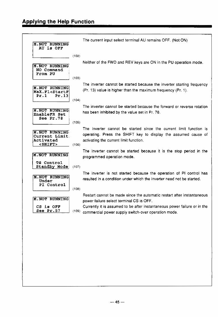
AU is OFF
NO Command From PU
M.NOT RUNNING MaX.Fl<StartF
The current input select terminal AU remains OFF. (Not ON)
102)
Neither of the FWD and REV keys are ON in the PU operation mode.
103)
The inverter cannot be started because the inverter starting frequency (Pr. 13) value is higher than the maximum frequency (Pr. 1).
The inverter cannot be started because the forward or reverse rotation -1 has been inhibited by the value set in Pr. 78. I See Pr. 78 I (105)
The inverter cannot be started since the current limit function is operating. Press the SHIFT key to display the assumed cause of M.NOT RUNNING
l A c ~ ~ ~ ? k ~ ? 1 (106) activating the current limit function.
TS Control
Under PI Control
The inverter cannot be started because it is the stop period in the programmed operation mode.
107)
The inverter is not started because the operation of PI control has resulted in a condition under which the inverter need not be started.
108)
Restart cannot be made since the automatic restart after instantaneous power failure select terminal CS is OFF. Currently it is assumed to be after instantaneous power failure or in the
(log) commercial power supply switch-over operation mode.
- 45 -
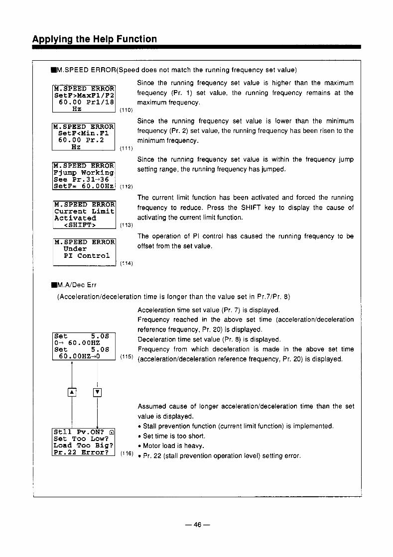
".SPEED ERROR(Speed does not match the running frequency set value)
Since the running frequency set value is higher than the maximum
SetF>MaxFl/F2 frequency (Pr. 1) set value, the running frequency remains at the 60.00 Pr1/18 maximum frequency.
(1 10)
Since the running frequency set value is lower than the minimum
SetF<Min.Fl frequency (Pr. 2) set value, the running frequency has been risen to the 60.00 Pr. 2 minimum frequency.
(111)
Since the running frequency set value is within the frequency jump setting range, the running frequency has jumped. F jump Working
See Pr.31436
The current limit function has been activated and forced the running frequency to reduce. Press the SHIFT key to display the cause of Current Limit
Activated activating the current limit function. (1 13)
The operation of PI control has caused the running frequency to be 7 1 offset from the set value. M.SPEED ERROR
MM.A/Dec Err (Acceleration/deceleration time is longer than the value set in Pr.7/Pr. 8)
Acceleration time set value (Pr. 7) is displayed. Frequency reached in the above set time (acceleration/deceleration reference frequency, Pr. 20) is displayed. Deceleration time set value (Pr. 8 ) is displayed. Frequency from which deceleration is made in the above set time
0- 60. OOHZ
OH'+' ( l 1 5 ) (acceleration/deceleration reference frequency, Pr. 20) is displayed. 1
Assumed cause of longer acceleration/deceleration time than the set value is displayed. 0 Stall prevention function (current limit function) is implemented.
Set Too Low? 0 Set time is too short. Load Too B i g ? 0 Motor load is heavy.
(116) 0 Pr. 22 (stall prevention operation level) setting error.
- 46 -
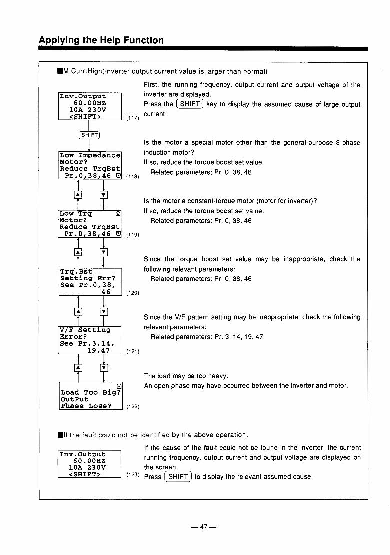
Applying the Help Function
HM.Curr.High(1nverter output current value is larger than normal)
First, the running frequency, output current and output voltage of the
6 0 . OOHZ Press the (E) key to display the assumed cause of large output 1nv.Output inverter are displayed.
10A 230V <SHIFT> (1 17)
current.
[SHIFT)
I Is the motor a special motor other than the general-purpose 3-phase
Low Impedance induction motor? Motor? Reduce TrqBst
If so, reduce the torque boost set value.
Pr.0,38,46 B (118) Related parameters: Pr. 0, 38, 46
Is the motor a constant-torque motor (motor for inverter)?
Low T r g a If so, reduce the torque boost set value. Motor? Reduce TrgBst
Related parameters: Pr. 0, 38, 46
Pr.0,38,46 5 (119) + A A
+ 6 (120)
1 Since the torque boost set value may be inappropriate, check the
Trq.Bst following relevant parameters: Setting E r r ? See Pr.0,38,
Related parameters: Pr. 0, 38, 46
Since the V/F pattern setting may be inappropriate, check the following relevant parameters:
Error? Related parameters: Pr. 3, 14, 19, 47 See Pr.3,14,
The load may be too heavy. An open phase may have occurred between the inverter and motor.
Load Too Big? output
=If the fault could not be identified by the above operation.
If the cause of the fault could not be found in the inverter, the current running frequency, output current and output voltage are displayed on 60. OOHZ
1OA 230V the screen. (123) Press (SHIFT) to display the relevant assumed cause.
-47-
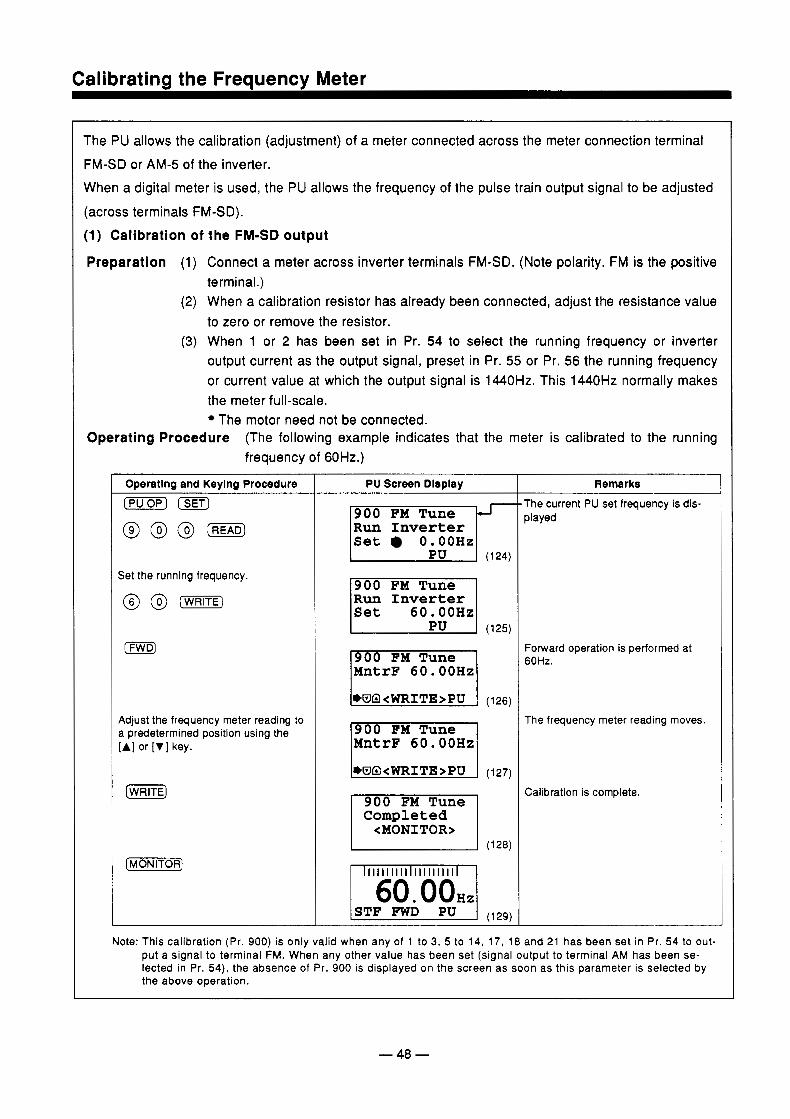
Calibratina the Freauencv Meter
The PU allows the calibration (adjustment) of a meter connected across the meter connection terminal FM-SD or AM-5 of the inverter. When a digital meter is used, the PU allows the frequency of the pulse train output signal to be adjusted (across terminals FM-SD). (1) Calibration of the FM-SD output
Preparation (1) Connect a meter across inverter terminals FM-SD. (Note polarity. FM is the positive
(2) When a calibration resistor has already been connected, adjust the resistance value
(3) When 1 or 2 has been set in Pr. 54 to select the running frequency or inverter output current as the output signal, preset in Pr. 55 or Pr. 56 the running frequency or current value at which the output signal is 1440Hz. This 1440Hz normally makes the meter full-scale.
The motor need not be connected.
terminal.)
to zero or remove the resistor.
Operating Procedure (The following example indicates that the meter is calibrated to the running frequency of 6OHz.)
Operating and Keylng Procedure
Set the running frequency.
@ @ [WRITE)
(FWD]
Adjust the frequency meter reading to a predetermined position using the [AI or [VI key.
PU Screen Dlsplay
Run Inverter Set 0. OOHz
(124)
900 FM Tune Run Inverter
(125)
MntrF 60.00Hz
MntrF 60.00Hz
Completed <MONITOR>
(1 28)
I IIIIIIIIIIIIIIIIIIIII I
Remarks 'he current PU set frequency is dis- dayed
'orward operation is performed at SOHz.
The frequency meter reading moves.
Zalibration is complete.
Note: This calibration (Pr. 900) is only valid when any of 1 to 3, 5 to 14, 17, 18 and 21 has been set in Pr. 54 to out- put a signal to terminal FM. When any other value has been set (signal output to terminal AM has been se- lected in Pr. 54), the absence of Pr. 900 is displayed on the screen as soon as this parameter is selected by the above operation.
-48 -
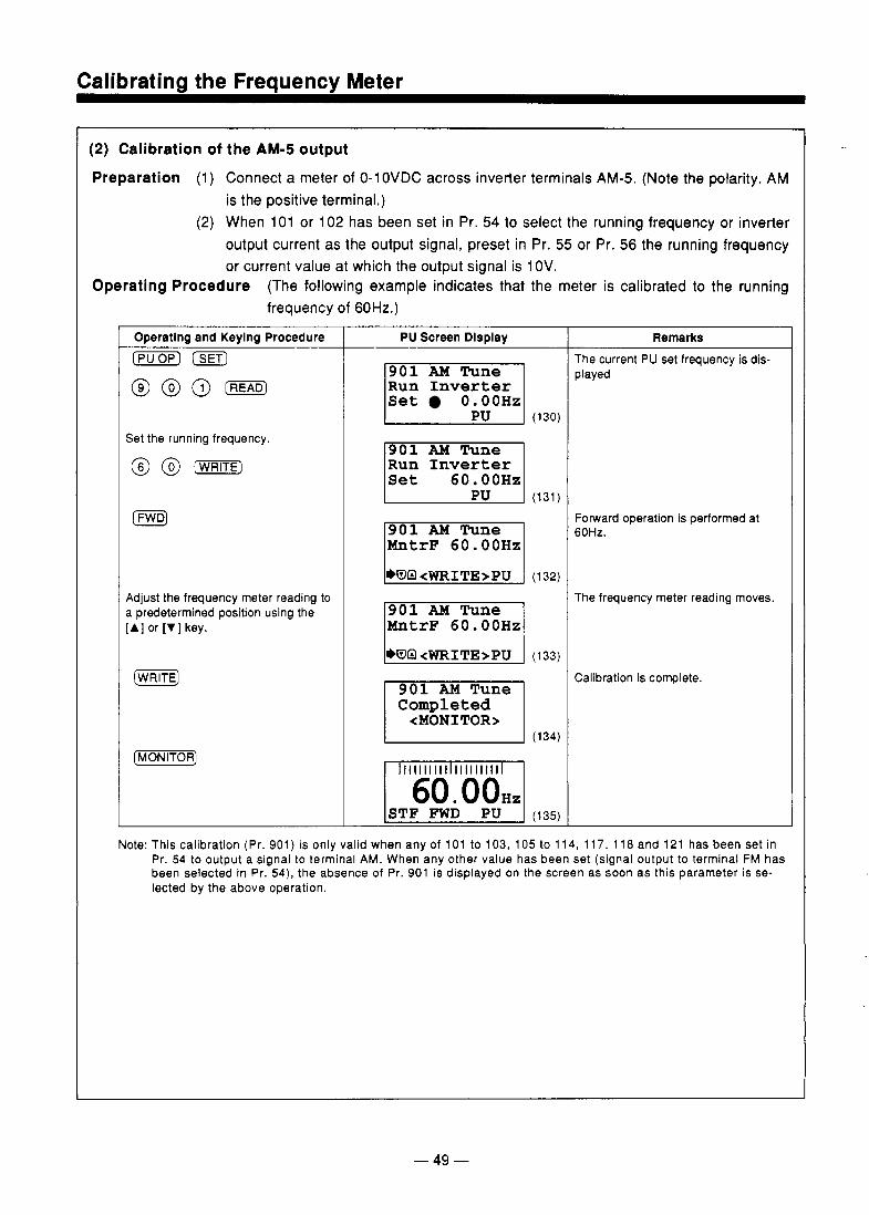
Calibrating the Frequency Meter
(2) Calibration of the AM-5 output Preparation (1) Connect a meter of 0-1OVDC across inverter terminals AM-5. (Note the polarity. AM
is the positive terminal.) (2) When 101 or 102 has been set in Pr. 54 to select the running frequency or inverter
output current as the output signal, preset in Pr. 55 or Pr. 56 the running frequency or current value at which the output signal is 1 OV.
Operating Procedure (The following example indicates that the meter is calibrated to the running frequency of 60Hz.) I
Operating and Keylng Procedure [ p u ) ISET)
@ @ 0 (m)
Set the running frequency.
@ @ [m)
[FWDJ
Adjust the frequency meter reading to a predetermined position using the [A] or [VI key.
(GiFE)
( M o N R )
PU Screen Dlsplay
Run Inverter Set O.OOHz
(1 30)
901 AM Tune Run Inverter
(131)
MntrF 60.00Hz
MntrF 60.00Hz
Completed <MONITOR>
(134)
IIIIIIIII IIIIIIIII
STF FWD PU (135)
Remarks The current PU set frequency is dis- played
Forward operation is performed at 60Hz.
The frequency meter reading moves.
Calibration is complete.
Note: This calibration (Pr. 901) is only valid when any of 101 to 103, 105 to 114, 117, 118 and 121 has been set in Pr. 54 to output a signal to terminal AM. When any other value has been set (signal output to terminal FM has been selected in Pr. 54) , the absence of Pr. 901 is displayed on the screen as soon as this parameter is se- lected by the above operation.
- 49 -
.. .
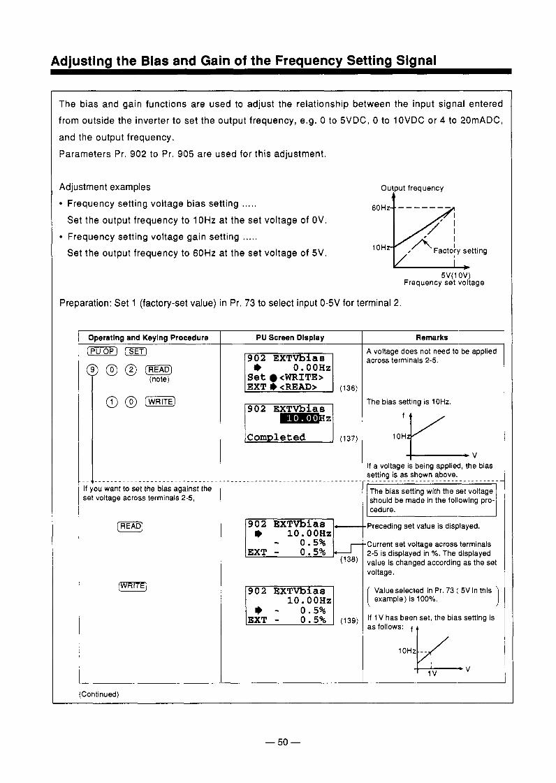
Adjusting the Bias and Gain of the Frequency Setting Signal
The bias and gain functions are used to adjust the relationship between the input signal entered from outside the inverter to set the output frequency, e.g. 0 to 5VDC, 0 to 10VDC or 4 to 20mADC, and the output frequency. Parameters Pr. 902 to Pr. 905 are used for this adjustment.
Adjustment examples Frequency setting voltage bias setting ..... Set the output frequency to lOHz at the set voltage of OV. Frequency setting voltage gain setting ..... Set the output frequency to 60Hz at the set voltage of 5V.
5V( 1 OV) Frequency set voltage
Preparation: Set 1 (factory-set value) in Pr. 73 to select input O W for terminal 2.
Operating and Keylng Procedure ( o p ) [ S E T ]
)a@- (note)
I- if you want to set the bias against the set voltage across terminals 2-5,
[READ)
PU Screen Display
0. OOHz Set <WRITE>
902 EXTVbias 10. OOHz
0 .5%
Remarks A voltage does not need to be applied across terminals 2-5.
The bias setting is 10Hz.
1 OH fv -v
If a voltage is being applied, the bias setting is as shown above. -_________--_____..--------------
should be made in the following pro- cedure.
Preceding set value is displayed.
Current set voltage across terminals 2-5 is displayed in %. The displayed value is changed according as the set voltage.
Value selected in Pr. 73 ( 5V in this example) is 100%.
If 1 V has been set, the bias setting is as follows: f t
lOHz - - v, (Continued)
- 50 -
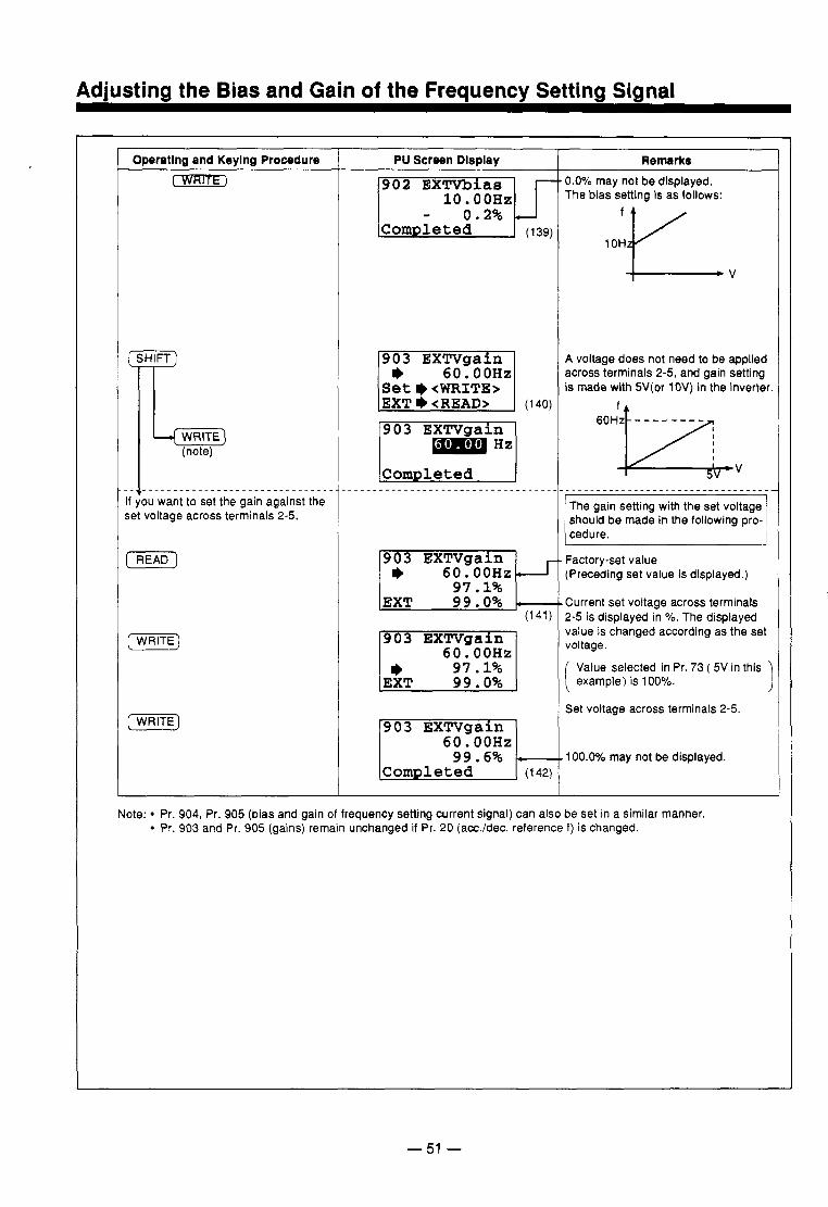
Adjusting the Bias and Gain of the Frequency Setting Signal
Operatlno and Keylno Procedure TwRlrr)
3
+ZKE-) (note)
[READ)
(WRITE)
(WRITE)
Pu screen DlsDlay
902 EXTVblas 10. OOHz
______.________._____________
903 EXTVgaln 60. OOHz 97.1% 99.0%
903 EXTVgaln 60. OOHz 97.1% 99.0%
(141)
60. OOHz 99.6%
Remarks 0.0% may not be displayed. The bias setting is as follows:
1 OH fv A voltage does not need to be applied across terminals 2-5, and gain setting is made with 5V(or 1OV) in the inverter
_--._____-_______._______________
should be made in the following pro-
Factory-set value (Preceding set value is displayed.)
Current set voltage across terminals 2-5 is displayed in %. The displayed value is changed according as the set voltage.
Value selected in Pr. 73 ( 5V in this example) is 100%.
Set voltage across terminals 2-5.
1 OO.OV0 may not be displayed.
Note: Pr. 904, Pr. 905 (bias and gain of frequency setting current signal) can also be set in a similar manner. Pr. 903 and Pr. 905 (gains) remain unchanged if Pr. 20 (acc./dec. reference f ) is changed.
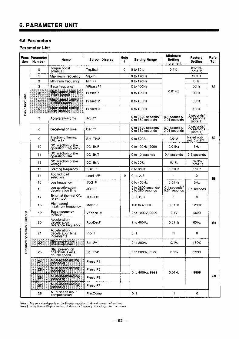
6. PARAMETER UNIT
6.5 Parameters Parameter List
lefer To : -
56
Screen Display I N:te I Setting Range Minlmum Setting
increment
0.1%
Factory Settlng
(note 1) 6%/3% l o I Torque boost
(manuall I Trq.Bst1
I 1 1 Maximum frequency 1 Max.Fl I I 0 to 120Hz 120Hz 0 Hz --
2 I Minimum frequency I Min.Fl I 0 to 120Hz 3 1 Base freauencv I VFbaseFl I 0 to 400Hz 60Hz
0.01 Hz 60Hz
30Hz
1 OHz m 1 7 1 Acceleration time
Acc.Tl I 1 0 to 3600 seconds/ 0 to 360 seconds
1.1 seconds/ 1.01 seconds 15 seconds
5 seconds/ (note 1 )
1 8 I Deceleration time Dec.Tl I / 0 to 3600 seconds/ 0 to 360 seconds
3.1 seconds1 1.01 seconds 15 seconds
5 seconds/ (note 1)
put current Rated out-
3 Hz
0.5 seconds
--
--
57 Electronic thermal O/L relay DC in'ection brake
Set THM 0 to 500A
10 operalion frequency DC Br.F 0 to 120Hz,9999
0.01 A
0.01 Hz
0.1 seconds I l l / \ DC in'ection brake DC B ~ , T oDera Ion tlme I I 0 to 10 seconds
I l2 I DC injection brake DC B ~ . V voltaae 0.1 o/o 6%/3?'0
(note ll __- 0.5Hz I 13 1 Startina freauencv I Start F I I 0 to 60Hz 0.01 Hz
0 14 sekction Ap lied load Load VF 0 0, 1,2, 3
15 Joa freauencv JOG F 0 to 400Hz
1
0.01 Hz 58
0.5 seconds l6
17
deceleration time Jog acceleration/ 0 to 3600 seconds/
External thermal OIL relay input 0, 1,293
0 to 360 seconds
JOG/OH
0.1 seconds/ 1.01 seconds
1 0
I 18 1 High-speed I maximum freauencv I I I 120 to 400Hz 0.01 Hz 120Hz
0.1v 9999 v1 c 0 0 3
Base frequency '9 voltage VFbase V 0 to 1 ooov, 9999 .- L
c Acceleration/ c 20 deceleration Acc/DecF 1 to 400Hz 5 - Acceleration/ E a 21 deceleration time 1ncr.T 0, 1 8 h
reference frequency .-
Increments
0 to 200%
m Stall prevention 5 23 operation level at Stll Pv2 double meed
0 to 200%, 9999
0.01 Hz 60Hz 59
1 0
0.1 %
0.1 % 9999
0 to 400Hz, 9999 0.01 Hz 9999 60
- 1 0 28 compensation Multi-speed input P r e , ~ o m p 0, 1
Note 1 The set value depends on the inverter capacity. (7 5K and down)/( l lK and up) Note 2 : In the Screen Display section, f indicates a frequency, V a voltage, and I a current
- 52 -
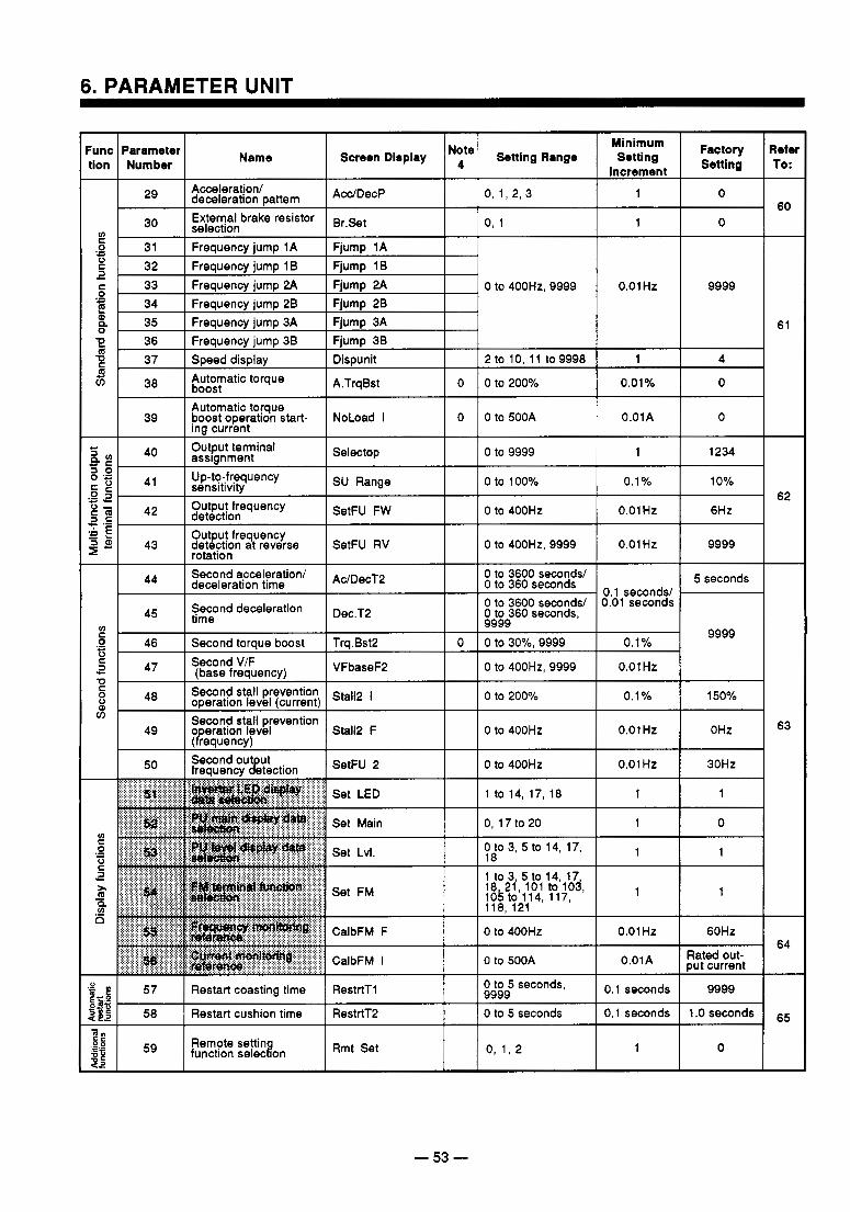
6. PARAMETER UNIT
0 to 400Hz, 9999
- 53 -
60
-
61
62
-
63
64
-
65
-
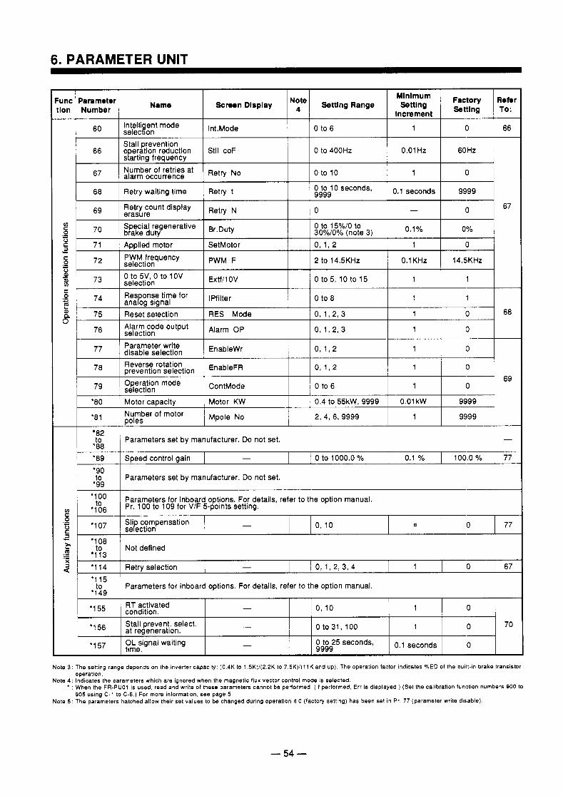
Func Number tlon
Parameter Name Settlng Range Note Screen Dlsplay Factory Refel Increment
-‘lng TO: Setting
1 60 I SelecWon lntelli ent mode Int.Mode 0 to 6 1 0 I 66
66
Retry N~ Number of retries at 67
Stll coF o eration reduction Stall prevention sParting frequency
alarm occurrence
0 to 400Hz 0.01 Hz 60 Hz
0 to 10 0 1
I 68 I Retry waiting time I Retry t 1 I 1 I
69 Retry count display erasure Retry 0 - 0 67
77 1 disable selection qarameter write EnableWr 1
1 78 I Dreventlon selection I Reverse rotation ~ n a b l e ~ ~
79 Operation mode ContMode 0 to 6 1
‘80 Motor caDacitv Motor KW 0.4 to 55kW, 9999 0.01 kW selection
‘81 Mpole No Number of motor poles ~ 1 2, 4, 6, 9999
1 9999 I 82
Parameters set by manufacturer. Do not set. I - ~ ‘89 I SDeed control aain I - I 0 to 1000.0 % I 0.1 I l O O & % - b -
_ _
‘90 I ‘$09 I Parameters set by manufacturer. Do not set.
v1 Pr. 100 to 109 for V/F 5-points setting. .,t&
‘’0° Parameters for inboard options. For details, refer to the option manual.
C 0
C
.- - Sli compensation 0 77 0 6 0 , i o - sekctlon a 2 to
0 I 67 1 1 0 , 1 , 2 , 3 , 4 - Retry selection ‘1 14 3
Not defined c ‘1 08
‘113 .- - .- X
‘1 15 to Parameters for inboard options. For details, refer to the option manual.
*I AQ
’’ condltlon.
‘I 56
*1 57
at regeneration.
OL signal waiting m e .
RT activated
- Stall prevent. select.
0 1 0 , lO -
0 to 31, 100 70 0 1
- 0.1 seconds 0 to 25 seconds, 9999 0
Note 3 : The setting range depends on the Inverter capacity (0.4K to 1 5K)/(2 2K lo 7 .5K) / ( l lK and up). The operation factor indicates %ED of the bullt-In brake transistor
Note 4 : Indicates the parameters which are ignored when the magnetic flux vector control mode is selected. operation
* : When the FR-PUOl is used, read and write of these parameters cannot be performed (I1 performed, Err is dlsplayed.) (Set the calibration (unction numbers 900 to
Note 5 ’ The parameters hatched allow their set values to be changed during operation if 0 (factory setting) has been set in Pr. 77 (parameter write disable) 905 using C-1 to C-6.) For more information, see page 5
- 54 -
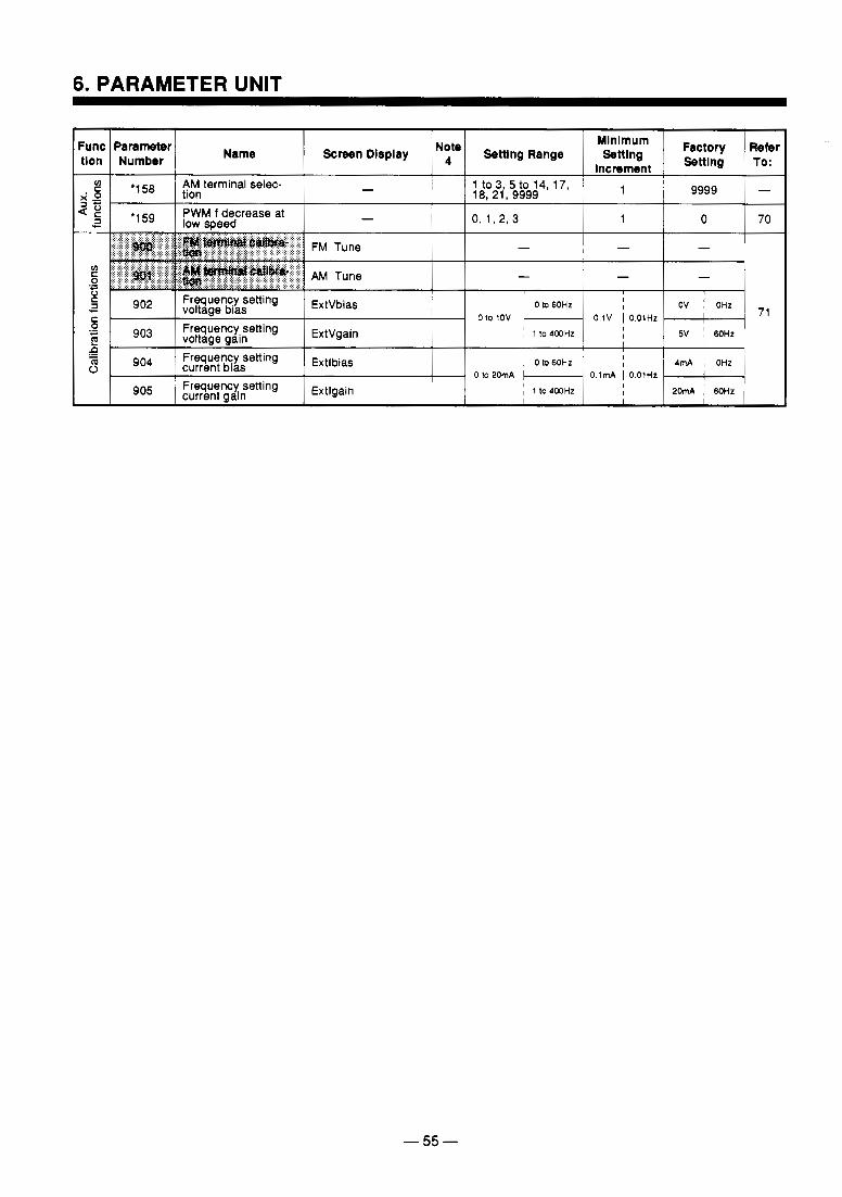
6. PARAMETER UNIT
- 55 -
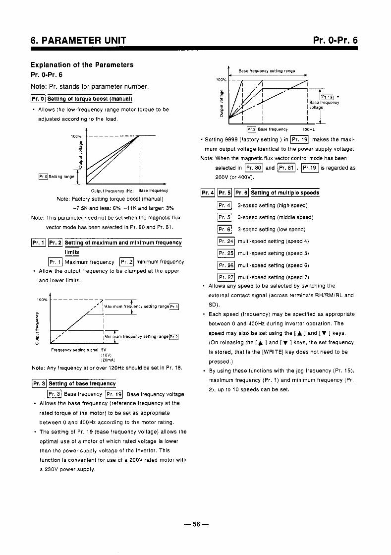
6. PARAMETER UNIT Pr. 0-Pr. 6
Explanation of the Parameters Pr. 0-Pr. 6 Note: Pr. stands for parameter number. a Setting of torque boost (manual)
Allows the low-frequency range motor torque to be adjusted according to the load.
,ooyo ------- \
L V * Output frequency (Hz) Base frequency
Note: Factory setting torque boost (manual) -7.5K and less: 6% -1 1 K and larger: 3%
Note: This parameter need not be set when the magnetic flux
vector mode has been selected in Pr. 80 and Pr. 81.
m2] Settlng of maxlmum and mlnlmum frequency - ilmits - Maximurn frequency minimum frequency
Allow the output frequency to be clamped at the upper and lower limits.
4
Frequency setting signal 5 V ( 1 o w (20mA)
Note: Any frequency at or over 120Hz should be set in Pr. 18.
Setting of base frequency
Base frequency [ P r . \ Base frequency voltage Allows the base frequency (reference frequency at the
rated torque of the motor) to be set as appropriate between 0 and 400Hz according to the motor rating. The setting of Pr. 19 (base frequency voltage) allows the optimal use of a motor of which rated voltage is lower than the power supply voltage of the inverter. This function is convenient for use of a 200V rated motor with a 230V power supply.
Base frequency setting range
Base frequency 400Hz
* Setting 9999 (factory setting ) in IPr. 191 makes the maxi- mum output voltage identical to the power supply voltage.
Note: When the magnetic flux vector control mode has been selected in and V I , is regarded as 200V (or 400V).
F6] Setting of multiple speeds
3-speed setting (high speed)
3-speed setting (middle speed)
3-speed setting (low speed)
IPr. 241 multi-speed setting (speed 4)
multi-speed setting (speed 5 )
IPr. 261 multi-speed setting (speed 6)
multi-speed setting (speed 7) Allows any speed to be selected by switching the external contact signal (across terminals RHIRMIRL and SD). Each speed (frequency) may be specified as appropriate between 0 and 400Hz during inverter operation. The
speed may also be set using the [ A ] and [ V ] keys. (On releasing the [A ] and [ V ] keys, the set frequency is stored, that is the [WRITE] key does not need to be pressed.) By using these functions with the jog frequency (Pr. 15), maximum frequency (Pr. 1) and minimum frequency (Pr. 2), up to 10 speeds can be set.
- 56 -
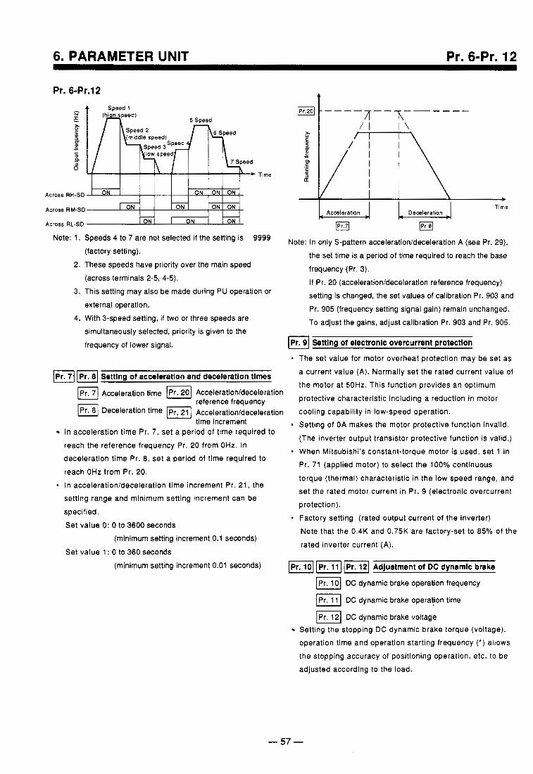
6. PARAMETER UNIT Pr. 6-Pr. 12
Pr. 6-Pr.12 4 Soeed 1
N
I, 2.
C
t L
a
- +
a
Across RH-SD
Across RM-SD E ON ON
Across RL-SD ON I ON ON - -
Note: 1.
2.
3.
4.
Speeds 4 to 7 are not selected if the setting is 9999 (factory setting). These speeds have priority over the main speed (across terminals 2-5, 4-5). This setting may also be made during PU operation or external operation. With 3-speed setting, if two or three speeds are simultaneously selected, priority is given to the frequency of lower signal.
Setting of acceleration and deceleration tlmes
Ameleration time Acceleration/deceleration
Deceleration time [ P r . ] Accelerationldeceleration reference frequency
time increment In acceleration time Pr. 7, set a period of time required to reach the reference frequency Pr. 20 from OHz. In deceleration time Pr. 8, set a period of time required to
reach OHz from Pr. 20. In acceleration/deceleration time increment Pr. 21, the setting range and minimum setting increment can be
specified. Set value 0: 0 to 3600 seconds
Time
Note: In only S-pattern acceleration/deceleration A (see Pr. 29), the set time is a period of time required to reach the base
frequency (Pr. 3). If Pr. 20 (acceleration/deceleration reference frequency) setting is changed, the set values of calibration Pr. 903 and Pr. 905 (frequency setting signal gain) remain unchanged. To adjust the gains, adjust calibration Pr. 903 and Pr. 905.
Setting of electronic overcurrent protection ~ ~ _ _ _
(minimum setting increment 0.1 seconds)
Set value 1 : 0 to 360 seconds
The set value for motor overheat protection may be set as a current value (A). Normally set the rated current value of the motor at 50Hz. This function provides an optimum protective characteristic including a reduction in motor cooling capability in low-speed operation. Setting of OA makes the motor protective function invalid. (The inverter output transistor protective function is valid.) When Mitsubishi's constant-torque motor is used, set 1 in Pr. 71 (applied motor) to select the 100% continuous torque (thermal) characteristic in the low speed range, and set the rated motor current in Pr. 9 (electronic overcurrent protection). Factory setting (rated output current of the inverter) Note that the 0.4K and 0.75K are factory-set to 85% of the rated inverter current (A).
(minimum setting increment 0.01 seconds) Adjustment of DC dynamic brake
I Pr. 101 DC dynamic brake operation frequency
DC dynamic brake opera!ion time
IPr. 121 DC dynamic brake voltage Setting the stopping DC dynamic brake torque (voltage), operation time and operation starting frequency (* ) allows the stopping accuracy of positioning operation, etc. to be adjusted according to the load.
.
- 57 -
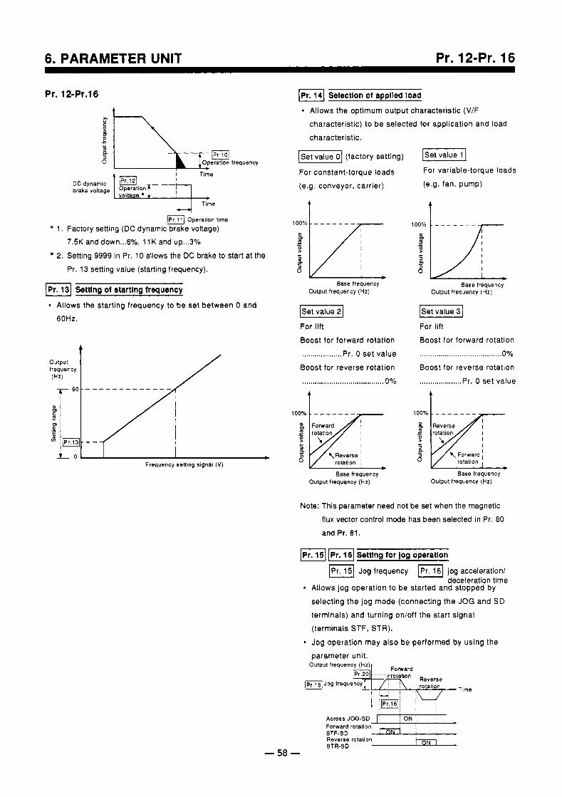
6. PARAMETER UNIT Pr. 12-Pr. 16
Pr. 12-Pr.16 I
Time
Operation time * 1 . Factory setting (DC dynamic brake voltage)
7.5K and down ... 6%, 11K and up ... 3% * 2. Setting 9999 in Pr. 10 allows the DC brake to start at the
Pr. 13 setting value (starting frequency).
IPr. 13) Setting of starting frequency
Allows the starting frequency to be set between 0 and 60Hz.
output frequency (Hz) /
IPr. 141 Selection of appiled load
Allows the optimum output characteristic (V/F characteristic) to be selected for application and load characteristic.
( S e t 1 (factory setting) F l For constant-torque loads (e.g. conveyor, carrier)
t
Output frequency (Hz) Base frequency
(Set value 21
For lift Boost for forward rotation ................... Pr. 0 set value Boost for reverse rotation ...................... ................. 0% A
Frequency setting slgnal (V)
Output frequency (Hz) Base frequency
For variable-torque loads (e.g. fan, pump)
t
Output frequency (Hz) Base frequency
I Set value 3 1 For lift Boost for forward rotation .. ... . . . ... .... . . . . . .. . ... . . . ... .. * . . . .O% Boost for reverse rotation .................... Pr. 0 set value
t a a 7 Forward I
rotatlon
Base frequency Output frequency (Hz)
Note: This parameter need not be set when the magnetic flux vector control mode has been selected in Pr. 80 and Pr. 81.
( P r . 1 I p I . 1 setting tor jog operation
( P r . 1 Jog frequency 1 1 6 1 jog acceleration/ deceleration time
Allows jog operation to be started and stopped by selecting the jog mode (connecting the JOG and SD terminals) and turning on/off the start signal (terminals STF, STR).
Jog operation may also be performed by using the parameter unit.
Across JOG-SD I I I ON Forward rotation STF-SD
STR-SD
8 ,
- 58 -
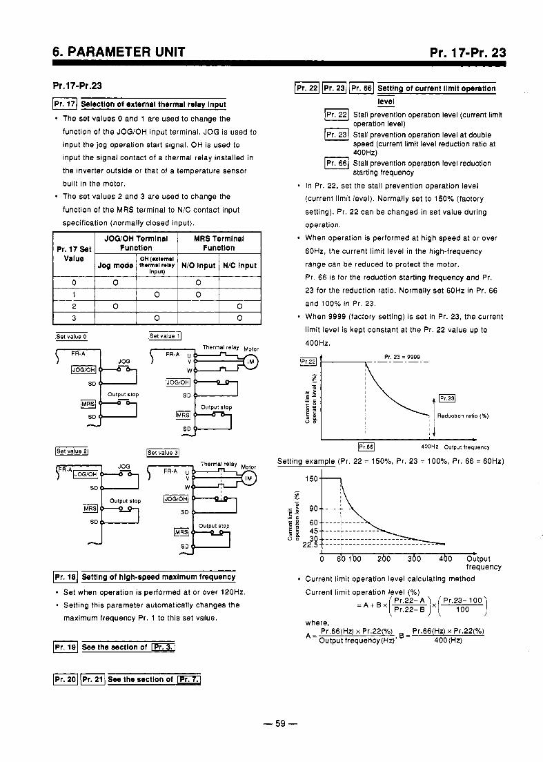
6. PARAMETER UNIT Pr. 17-Pr. 23
Pr.17-Pr.23 Seloctlon of external thermal relay Input
The set values 0 and 1 are used to change the function of the JOGlOH input terminal. JOG is used to input the jog operation start signal. OH is used to input the signal contact of a thermal relay installed in the inverter outside or that of a temperature sensor built in the motor. The set values 2 and 3 are used to change the
function of the MRS terminal to N/C contact input specification (normally closed input).
JOWOH Tennlnal MRS Termlnal Pr. 17 Set Functlon
~ Functlon Value OH (extenui
Jog mode N E Input N/O Input th.rm.1 relay Input)
0
0 0 3 0 0 2
0 0 1 0 0
Output stop
SD 4
d
Semng of hlgh-speed maxlmum frequency
Set when operation is performed at or over 120Hz. Setting this parameter automatically changes the maximum frequency Pr. 1 to this set value.
IpI.22) - Setttng of current limit operatlon level
Stall prevention operation level (current limit - , . , operation level)
Pr 23 Stall prevention operation level at double speed (current limit level reduction ratio at
E:lyi:evention operation level reduction starting frequency
In Pr. 22, set the stall prevention operation level (current limit level). Normally set to 150% (factory setting). Pr. 22 can be changed in set value during operation. When operation is performed at high speed at or over 60Hz, the current limit level in the high-frequency range can be reduced to protect the motor. Pr. 66 is for the reduction starting frequency and Pr. 23 for the reduction ratio. Normally set 60Hz in Pr. 66 and 10Ooh in Pr. 23. When 9999 (factory setting) is set in Pr. 23, the current limit level is kept constant at the Pr. 22 value up to 400Hz.
Setting example (Pr. 22 = 150%, Pr. 23 = 100%
q-7
F l ( p r . 1 See the sectlon of
- 59 -
I i \
Pr. 66 =
I b o 6'0 1'00 2b0 360 4b0 Output frequency
Current limit operation level calculating method Current limit operation level (Yo)
Pr.22-'A Pr.23- 100 'AiBx[Pr.22-B)X( 100 1
where, A= Pr.66(Hz) x Pr.22(%) = Pr.66(Hz) x Pr.22(%)
Output frequency(Hz)' 400(Hz)
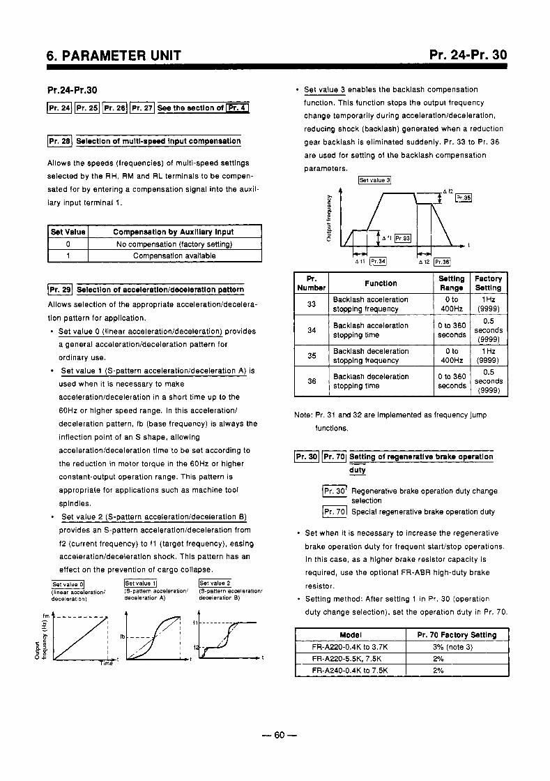
6. PARAMETER UNIT Pr. 24-Pr. 30
Pr.24-Pr.30 F24) f i l See the sectlon of
I p I . 1 Selection of multi-speed input compensation
Allows the speeds (frequencies) of multi-speed settings selected by the RH, RM and RL terminals to be compen- sated for by entering a compensation signal into the auxil- iary input terminal 1.
Set Value
Compensation available 1 No compensation (factory setting) 0
Compensation by Auxiilary input
0 Pr 29 Selection of acceleration/deceleratlon pattern
Allows selection of the appropriate acceleration/decelera-
tion pattern for application. Set value 0 (linear acceleration/deceleration) orovides a general acceleration/deceleration pattern for ordinary use. Set value 1 (S-pattern acceleration/deceleration A) is
used when it is necessary to make acceleration/deceleration in a short time up to the 60Hz or higher speed range. In this acceleration/ deceleration pattern, fb (base frequency) is always the inflection point of an S shape, allowing acceleration/deceleration time to be set according to the reduction in motor torque in the 60Hz or higher constant-output operation range. This pattern is appropriate for applications such as machine tool spindles. Set value 2 (S-pattern acceleration/deceleration 6)
provides an S-pattern acceleration/deceleration from
f2 (current frequency) to f l (target frequency), easing acceleration/deceleration shock. This pattern has an effect on the prevention of cargo collapse.
( S e t v a l u e 1 -1 (linear acceleration/ (S-pattern acceleration1 (S-pattern acceleration1
Set value 3 enables the backlash compensation function. This function stops the output frequency change temporarily during acceleration/deceleration, reducing shock (backlash) generated when a reduction gear backlash is eliminated suddenly. Pr. 33 to Pr. 36 are used for setting of the backlash compensation parameters.
I NuFker I Function Setting Factory I Range 1 Settina - -
++ 1 Backlash acceleration 1 Oto 1 1Hz JJ I stopping frequency I 400Hz I (9999)
Backlash acceleration 0.5 34 stopping time
(9999) seconds
to 360 seconds
35 1 Hz 0 to Backlash deceleration stopping frequency (9999) 400Hz
I 36 I Backlash deceleration stopping time
0.5
Note: Pr. 31 and 32 are implemented as frequency jump functions.
I P r . 1 Setting of regenerative brake operatlon - duty
1 3 0 1 Regenerative brake operation duty change selection
IPr. 70) Special regenerative brake operation duty
Set when it is necessary to increase the regenerative brake operation duty for frequent start/stop operations. In this case, as a higher brake resistor capacity is required, use the optional FR-ABR high-duty brake
resistor. Setting method: After setting 1 in Pr. 30 (operation duty change selection), set the operation duty in Pr. 70.
deceleration) deceleration A) deceleration B)
Pr. 70 Factory Setting FRA220-0.4K to 3.7K 3% (note 3) FR-AZ0-5.5K. 7.5K
I FR-A240-0.4K to 7.5K 2% I
- 60 -
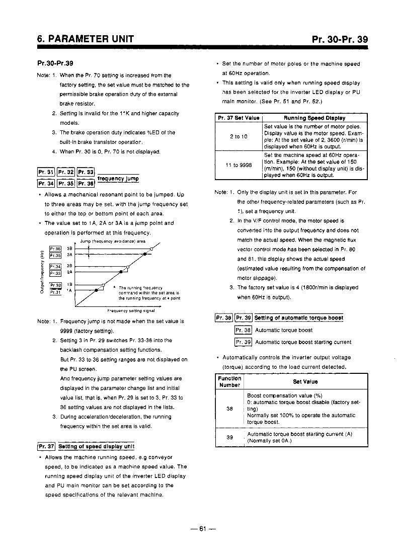
6. PARAMETER UNIT Pr. 30-Pr. 39
Pr.30-Pr.39 Note: 1. When the Pr. 70 setting is increased from the
factory setting, the set value must be matched to the permissible brake operation duty of the external brake resistor.
2. Setting is invalid for the 11 K and higher capacity models.
3. The brake operation duty indicates %ED of the built-in brake transistor operation.
4. When Pr. 30 is 0, Pr. 70 is not displayed.
Allows a mechanical resonant point to be jumped. Up to three areas may be set, with the jump frequency set to either the top or bottom point of each area. The value set to 1 A, 2A or 3 A is a jump point and operation is performed at this frequency.
. Jump (frequency avoldance) area ,
* The running frequency command within the set area is the running frequency at potnt
V c
Frequency sening slgnal
Note: 1. Frequency jump is not made when the set value is
9999 (factory setting). 2. Setting 3 in Pr. 29 switches Pr. 33-36 into the
backlash compensation setting functions.
But Pr. 33 to 36 setting ranges are not displayed on the PU screen. And frequency jump parameter setting values are displayed in the parameter change list and initial value list, that is, when Pr. 29 is set to 3, Pr. 33 to 36 setting values are not displayed in the lists.
3. During acceleration/deceleration, the running frequency within the set area is valid.
(Pr. 371 Settlng of speed display unit
Allows the machine running speed, e.g conveyor speed, to be indicated as a machine speed value. The running speed display unit of the inverter LED display and PU main monitor can be set according to the speed specifications of the relevant machine.
Set the number of motor poles or the machine speed at 60Hz operation. This setting is valid only when running speed display has been selected for the inverter LED display or PU main monitor. (See Pr. 51 and Pr. 52.)
disdaved when 60Hz is oubut. 'Set the machine speed at 60Hz opera- tion. Example: At the set value of 150
played when 60Hz is output.
l1 to (m/min), 150 (without display unit) is dis-
Note: 1. Only the display unit is set in this parameter. For the other frequency-related parameters (such as Pr. 1 ), set a frequency unit.
2. In the V/F control mode, the motor speed is converted into the output frequency and does not match the actual speed. When the magnetic flux vector control mode has been selected in Pr. 80 and 81, this display shows the actual speed (estimated value resulting from the compensation of motor slippage).
3. The factory set value is 4 (180Or/min is displayed
when 60Hz is output).
[Pr. 381 [ Pr. 391 Settlng of automatic torque boost
p38) Automatic torque boost
IPr. 391 Automatic torque boost starting current
Automatically controls the inverter output voltage (torque) according to the load current detected.
Function I Number ~
Set Value I
Boost compensation value ( O h )
0: automatic torque boost disable (factory set-
Normally set 100% to operate the automatic torque boost.
Automatic torque boost starting current (A)
38 ting)
39 (Normally set OA.)
- 61 -
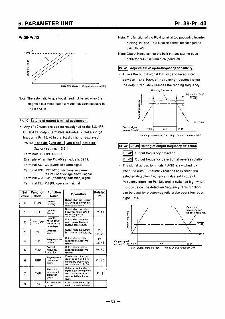
6. PARAMETER UNIT Pr. 39-Pr. 43
Pr.39-Pr.43
I
Base frequency Output frequency(H2)
Note: The automatic torque boost need not be set when the magnetic flux vector control mode has been selected in Pr. 80 and 81.
I P r . 1 Settlng of output terminal assignment
Any of 10 functions can be reassigned to the SU, IPF, OL and FU output terminals individually. Set a 4-digit integer in Pr. 40. (0 in the 1st digit is not displayed.) Pr. 40 : l l s td ig i t l -1 -1
(factory setting: 1 2 3 4) Terminals: SU IPF OL FU Example:When the Pr. 40 set value is 3249. Terminal SU: OL (overload alarm) signal Terminal IPF: IPF/UVT (instantaneous power
failure/undervoltage alarm) signal Terminal OL: FU1 (frequency detection) signal Terminal FU: PU (PU operation) signal
Set Function Function Related Code Name Pr.
Output when the inverter Inverter running
is running at or over the startina freauencv.
RUN
3
FU1 4
alarm 0'
specified detection fre- tecbon
ae , j oad pr. &pu t while bLe current limit function is operating. 22,23
Pr . Frequency de- Output at or over the
quency 42, 43 Second &pu t at or over the
detection
Swenerative
quency. Prealarm is ouwut on
5 Pr. 50 specified detection I r e frequency FU2
- - ~ - _ _ 7,, reaching 85% of che re- I 6 I RBP 1 $;;;P~w- generative brake opera- bon factor set In Pr. 70 I r" '" I
I
THP 7 aontc overcurrent protec- ~ ~ ~ $ n t Pr. 9 bon cumulative value
PTOteCtion
&@ut when the el--
alarm reaches 85% of the set level
Note: The function of the RUN terminal (output during inverter running) is fixed. This function cannot be changed by using Pr. 40.
Note: Output indicates that the built-in transistor for open collector output is turned on (conducts).
f i l Adjustment of up-to-frequency sensitivity
Allows the output signal ON range to be adjusted between 1 and 100% of the running frequency when the output frequency reaches the running frequency.
Runnlng frequency
3 a
yh Time
Output signal across SU-SE High I Low High
Low Output transistor ON High Output transistor OFF
Setting of output frequency detection
U 0 Pr 42 Output frequency detection
Pr 43 Output frequency detection at reverse rotation
The signal across terminals FU-SE is switched low when the output frequency reaches or exceeds the selected detection frequency (value set in output frequency detection Pr. 42), and is switched high when it drops below the detection frequency. This function can be used for electromagnetic brake operation, open signal, etc.
Detectlon frequency can E be set if required.
m u - + 2 a n a
Output signal across FU-SE High Low High
Low Output transistor ON High. Output transistor OFF
9 PU operation eration mode IS selected &pu t when the PU op-
- 62 -
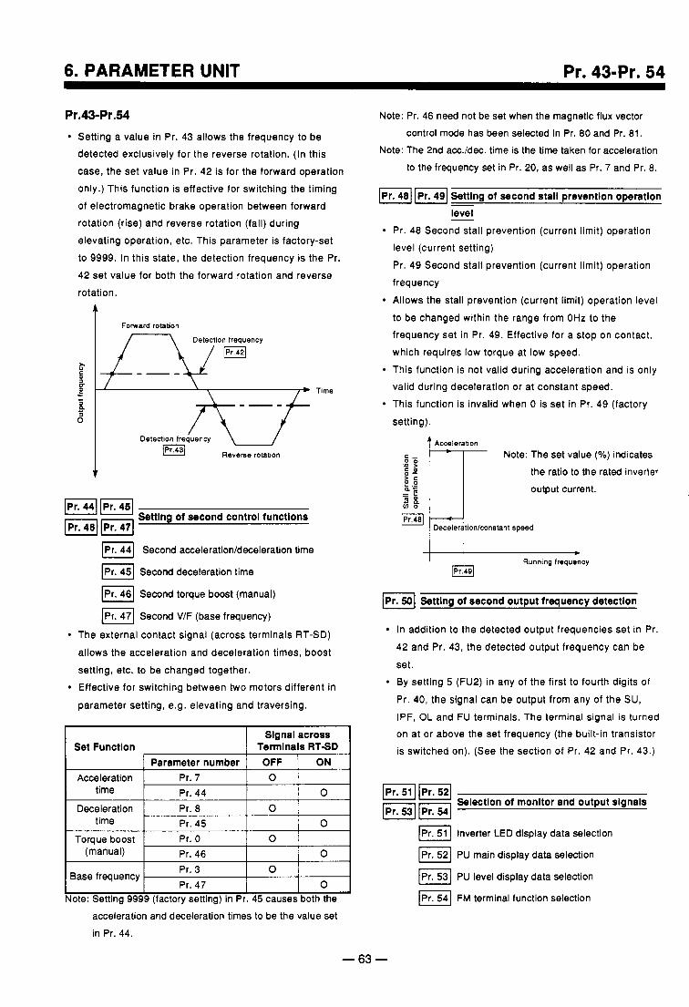
6. PARAMETER UNIT Pr. 43-Pr. 54
Pr.43-Pr.54 Setting a value in Pr. 43 allows the frequency to be detected exclusively for the reverse rotation. (In this case, the set value in Pr. 42 is for the forward operation only.) This function is effective for switching the timing of electromagnetic brake operation between forward rotation (rise) and reverse rotation (fall) during elevating operation, etc. This parameter is factory-set to 9999. In this state, the detection frequency is the Pr. 42 set value for both the forward rotation and reverse rotation.
Fomard rotation
Detection frequency
Time
Detection frequency w R e v e m rotation
IPr. 441 IPr. 451 U I
mm ' Settlng of second control functions
Second acceleration/deceleration time
IPr. 451 Second deceleration time
IPr. 46) Second torque boost (manual)
/PI. 471 Second V/F (base frequency)
The external contact signal (across terminals RT-SD)
allows the acceleration and deceleration times, boost setting, etc. to be changed together. Effective for switching between two motors different in
parameter setting, e.g. elevating and traversing.
Slgnal across
1 Parameter number OFF 1 ON Set Functlon Termlnais RTSD
Acceleration Pr. 7 1 0 1 time I o Pr. 44
Deceleration I Pr. 8 l o 1 I time
0 Pr. 46 (manual)
0 Pr. 45 Torque boost 0 Pr. 0
Base frequency Pr. 3 1 0 1 Pr. 47 I o I
lote: Setting 9999 (factory setting) in Pr. 45 causes both the acceleration and deceleration times to be the value set in Pr. 44.
Note: Pr. 46 need not be set when the magnetic flux vector control mode has been selected in Pr. 80 and Pr. 81.
Note: The 2nd acc./dec. time is the time taken for acceleration to the frequency set in Pr. 20, as well as Pr. 7 and Pr. 8.
f i ] Settlng of second stall prevention operation - level
Pr. 48 Second stall prevention (current limit) operation level (current setting) Pr. 49 Second stall prevention (current limit) operation frequency Allows the stall prevention (current limit) operation level
to be changed within the range from OHz to the frequency set in Pr. 49. Effective for a stop on contact, which requires low torque at low speed. This function is not valid during acceleration and is only valid during deceleration or at constant speed. This function is invalid when 0 is set in Pr. 49 (factory
setting).
Acceleration Note: The set value (YO) indicates
the ratio to the rated inverter a- output current.
I I Running frequency
Setting of second output frequency detection
In addition to the detected output frequencies set in Pr.
42 and Pr. 43, the detected output frequency can be
set. By setting 5 (FU2) in any of the first to fourth digits of
Pr. 40, the signal can be output from any of the SU, IPF, OL and FU terminals. The terminal signal is turned on at or above the set frequency (the built-in transistor is switched on). (See the section of Pr. 42 and Pr. 43.)
fil1Pr.l pqKq Selectlon of monitor and output slgnals
[Pr. 51 1 Inverter LED display data selection
PU main display data selection
0 Pr 53 PU level display data selection IPr. 541 FM terminal function selection
- 63 -
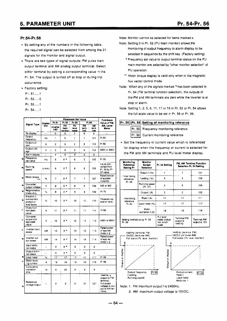
6. PARAMETER UNIT Pr. 54-Pr. 56
*
*
*
*
for display when the frequency or current is selected for the FM and AM terminals and PU level meter display.
Pr.54-Pr.56 Note: Monitor cannot be selected for items marked x.
By setting any of the numbers in the following table, Note: Setting 0 in Pr. 52 (PU main monitor) allows the the required signal can be selected from among the 21 monitoring of output frequency to alarm display to be
signals for the monitor and signal output. selected in sequence by the shift key. (Factory setting)
There are two types of signal outputs: FM pulse train Frequency set value to output terminal status on the PU
output terminal and AM analog output terminal. Select either terminal by setting a corresponding value in the PU operation. Pr. 54. The output is turned off at stop or during trip *' Motor torque display is valid only when in the magnetic occurrence. Factory setting:
main monitor are selected by "other monitor selection" of
flux vector control mode. Note: When any of the signals marked has been selected in
Pr. 51 ..... 1 Pr. 52 ..... 0 Pr. 53 ..... 1
Pr. 54 ..... 1
Pr. 54 (FM terminal function selection), the outputs of the FM and AM terminals are zero while the inverter is at stop or alarm.
Note: Setting 1, 2, 5, 6, 11, 17 or 18 in Pr. 53 or Pr. 54 allows the full scale value to be set in Pr. 55 or Pr. 56.
p55) J p r . 1 Settlng of monltorlng reference
Frequency monitoring reference
0 Pr 56 Current monitoring reference
Set the frequency or current value which is referenced
-
-
- I I -
>r; b/l* lOVDC (terminal AM) Full scale (PU level monitor)
_ _ _ _ _ _ _ _ _ - _ _
a n - 3 n
I
output frequency f setting
Output current IPr56/ Peak I
Running speed Load meter Motor ex. ~
Note: 1. FM maximum output f is 2400Hz. mind 2. AM maximum output voltage is 1 OVDC.
Output t (Hz)
Pr. 5 5 Running speed
(Pr. 37) 6 106
I Outputl (A) I 2 I 2 I 102 I I monitormg Peak I (A) 11 reference
Pr. 56 Load meter ( 4 6 ) 17 17
excitation I (A ) Motor
1440Hz ltermlnal FM) 1440Hz (termtnal FM)
-64-
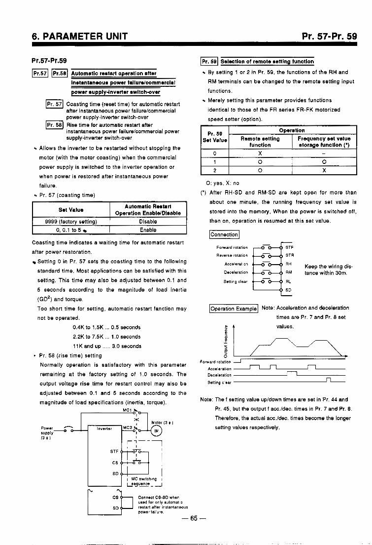
Pr. 57-Pr. 59
Pr.57-Pr.59 [p1.571 m p 1 . 5 8 1 Automatic restart operation after
instantaneous power failure/commercial power supply-inverter switch-over
Coasting time (reset time) for automatic restart after instantaneous power failurelcommercial power supply-inverter switch-over
Pr 58 Rise time for automatic restart after instantaneous power failure/commercial power supply-inverter switch-over
E l Allows the inverter to be restarted without stopping the motor (with the motor coasting) when the commercial power supply is switched to the inverter operation or when power is restored after instantaneous power failure
Pr. 57 (coasting time) ,
Selection of remote setting function
I Set Value I Automatic Restart Oseration EnabldDisable I
9999 (factory setting) Disable 0, 0.1 to 5 Enable
Coasting time indicates a waiting time for automatic restart after power restoration.
Setting 0 in Pr. 57 sets the coasting time to the following standard time. Most applications can be satisfied with this setting. This time may also be adjusted between 0.1 and 5 seconds according to the magnitude of load inertia
(GD2) and torque. Too short time for setting, automatic restart fanction may not be operated.
0.4K to 1.5K ... 0.5 seconds 2.2K to 7.5K ... 1 .O seconds 1 lK and up ..... 3.0 seconds
Pr. 58 (rise time) setting Normally operation is satisfactory with this parameter remaining at the factory setting of 1.0 seconds. The output voltage rise time for restart control may also be adjusted between 0.1 and 5 seconds according to the magnitude of load specifications (inertia, torque).
By setting 1 or 2 in Pr. 59, the functions of the RH and RM terminals can be changed to the remote setting input functions. Merely setting this parameter provides functions identical to those of the FR series FR-FK motorized
speed setter (option).
Pr. 59 . Operation Set Value
storage function (*) function Frequency set value Remote setting
0
X 0 2 0 0 1
- X
0: yes, X: no (*) After RH-SD and RM-SD are kept open for more than
about one minute, the running frequency set value is stored into the memory, When the power is switched off, then on, operation is resumed at this set value.
lconnection I
Reverse rotation E!T Forward rotation
Acceleration
Deceleration - tance within 30m. Keep the wiring dis-
Setting clear Pz* Operation Example Note: Acceleration and deceleration
times are Pr. 7 and Pr. 8 set
$ 4 values.
Forward rotation Acceleration Deceleration a Setting clear n
I sDP I MC switching I
Conned CS-SD when used for only automatic
power failure. restart aiter instantaneous
-65-
Note: The f setting value up/down times are set in Pr. 44 and Pr. 45, but the output f acc./dec. times in Pr. 7 and Pr. 8. Therefore, the actual acc./dec. times become the longer setting values respectively.
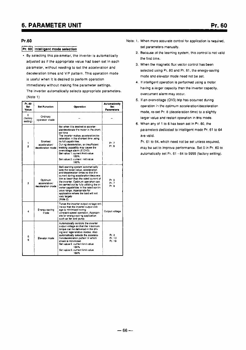
6. PARAMETER UNIT Pr. 60
Pr.60 I P r . 1 lntelllgent mode selectlon
By selecting this parameter, the inverter is automatically adjusted as if the appropriate value had been set in each parameter, without needing to set the acceleration and deceleration times and V/F pattern. This operation mode is useful when it is desired to perform operation immediately without making fine parameter settings. The inverter automatically selects appropriate parameters. (Note 1) -
Pr. 80 set
Value
0
ietting:
- factor)
1 2
3
-
A
5 6
Set Functlon ~~ ~~
Ordinary operation mode
acwIeration/ Shortest
deceleration mode
accaleration/ Optimum
deceleration mode
Energy-saving mode
Elevator mode
Opention
-
Set when it is desired to acceler- atddecderate the motor in t h e short- est time. The inverter makes acceleratidde- celeration in the shortest time wing its full capabilities. During decaleration, an insufficient
overvoltage alarm (E.OV3). braking capability may cause the
Set value 1: current limlt value
S e t value 2: current limit value 1 5 0 %
180%
Self-learning system automatically sets the b o d valw. accsleration and decaleration times so that the current during accsleration/decelera- tion is lower than the rated current of the inverter. Optimum operation can
verter capabilities in the rated cantin- be carried out by fully utilizing the in-
uous range. Appopriate for application where the load will not vary largely. (Note 2) Tunes the inverter output voltage onl. ine so that the inverter output volt- age is minimized during constant-speed operation. Appropri- ate for energydaving application such as tan and plmp.
Automatically canto16 the inverter output voltage so that the maximum torque can be delivered in the driv- ing and regenerative modes. Also aummatically selects the accslera- tiorddecderation pattern in which shock is minimized Set value 5: c u m n l limit value
150% S e t value 6: current limit value
1 8 0 %
Pr. 7 Pr. 8
Pr. 0 Pr. 7 Pr. 8
Output VOlQgf
Pr. 0
Pr. 19 Pr. 13
Note: 1. When more accurate control for application is required, set parameters manually.
2. Because of the learning system, this control is not valid the first time.
3. When the magnetic flux vector control has been selected using Pr. 80 and Pr. 81, the energy-saving mode and elevator mode need not be set.
4. If intelligent operation is performed using a motor having a larger capacity than the inverter capacity, overcurrent alarm may occur.
5. If an overvoltage (OV3) trip has occurred during operation in the optimum acceleration/deceleration mode, re-set Pr. 8 (deceleration time) to a slightly larger value and restart operation in this mode.
6. When any of 1 to 6 has been set in Pr. 60, the parameters dedicated to intelligent mode Pr. 61 to 64 are valid.
Pr. 61 to 64, which need not be set unless required,
may be set to improve performance. Set 0 in Pr. 60 to automatically set Pr. 61 - 64 to 9999 (factory setting).
- 66 -
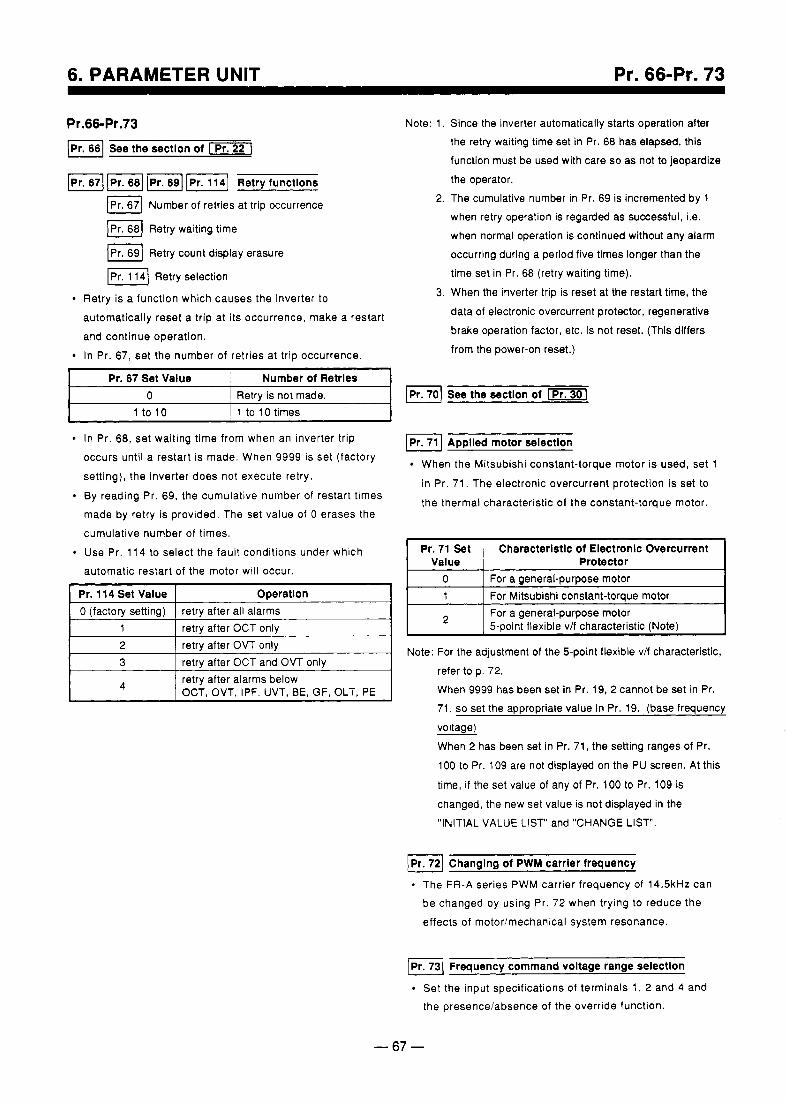
Pr. 66-Pr. 73
Pr.66-Pr.73 I P r . 1 See the sectlon of
f i l -1141 Retry functlons m67] Number of retries at trip occurrence
IPr. 68) Retry waiting time
IPr. 691 Retry count display erasure
1-1 Retry selection
Retry is a function which causes the inverter to automatically reset a trip at its occurrence, make a restart and continue operation. In Pr. 67, set the number of retries at trip occurrence.
I Pr. 67 Set Value ~ Number of Retrles I 0 I Retry is not made.
1 to 10
In Pr. 68, set waiting time from when an inverter trip
1 to 10 times
occurs until a restart is made. When 9999 is set (factory setting), the inverter does not execute retry. By reading Pr. 69, the cumulative number of restart times made by retry is provided. The set value of 0 erases the cumulative number of times. Use Pr. 114 to select the fault conditions under which automatic restart of the motor will occur.
retrv after OCT and OVT only retry after alarms below OCT, OVT, IPF, UVT, BE, GF, OLT, PE I
Note: 1. Since the inverter automatically starts operation after the retry waiting time set in Pr. 68 has elapsed, this function must be used with care so as not to jeopardize the operator.
2. The cumulative number in Pr. 69 is incremented by 1 when retry operation is regarded as successful, i.e. when normal operation is continued without any alarm occurring during a period five times longer than the time set in Pr. 68 (retry waiting time).
3. When the inverter trip is reset at the restart time, the data of electronic overcurrent protector, regenerative brake operation factor, etc. is not reset. (This differs from the power-on reset.)
[Pr.70) See the sectlon of -1
Applled motor selectlon
When the Mitsubishi constant-torque motor is used, set 1
in Pr. 71. The electronic overcurrent protection is set to the thermal characteristic of the constant-torque motor.
Pr. 71 Set Characterlstlc of Electronlc Overcurrent Value Protector
0 For Mitsubishi constant-toraue motor 1 For a general-purpose motor
For a general-purpose motor 5-ooint flexible v/f characteristic (Note)
~ ~~ ~ ~~ ~
Note: For the adjustment of the 5-point flexible v/f characteristic, refer to p. 72.
When 9999 has been set in Pr. 19,2 cannot be set in Pr. 71, so set the appropriate value in Pr. 19. (base frequency voltage) When 2 has been set in Pr. 71, the setting ranges of Pr. 100 to Pr. 109 are not displayed on the PU screen. At this
time, if the set value of any of Pr. 100 to Pr. 109 is changed, the new set value is not displayed in the "INITIAL VALUE LIST" and "CHANGE LIST.
f i ] Changing of PWM carrier frequency
The FR-A series PWM carrier frequency of 14.5kHz can be changed by using Pr. 72 when trying to reduce the effects of motorimechanical system resonance.
Frequency command voltage range selectlon
Set the input specifications of terminals 1, 2 and 4 and the presence/absence of the override function.
- 67 -
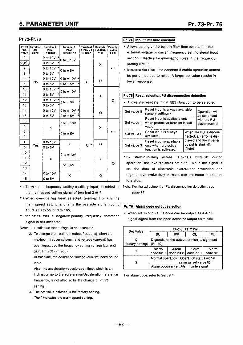
6. PARAMETER UNIT Pr. 73-Pr. 76
Pr.73-Pr.76 1 p I . l Input filter time constant Allows setting of the built-in filter time constant in the external voltage or current frequency setting signal input section. Effective for eliminating noise in the frequency setting circuit. Increase the filter time constant if stable operation cannot be performed due to noise. A larger set value results in lower response.
Termlnal 2 Termlnal 1 T r m l M l Overrlde Polarlfy
VoHage I Voltago *l to 20mA 1 2 blllty 1 Input Input 4lnpul, 4 Functlon Revoral
I
I I I h l I
O f O l O V O t o i l O V ' I x 0 to 5v 0 t O f 5 V *
Oto5V 4"' I o 0 to 1ov 0 t o ? 1ov * 0 to 5v 0 to + 5v * 0 1
0 to * 1ov X X
0 to * 5v * 3
0 to 1ov 0 to 5v
X o * 0
=Hr 0 to ? 1ov
0 to * 5v
0 to 1ov 0 to 5v
Reset selectlon/PU dlsconnectlon detection
Allows the reset (terminal RES) function to be selected.
* 1:Terminal 1 (frequency setting auxiliary input) is added to the main speed setting signal of terminal 2 or 4.
2:When override has been selected, terminal 1 or 4 is the
main speed setting and 2 is the override signal (50 to
15096 at 0 to 5 V or 0 to 1OV). 3:lndicates that a negative-polarity frequency command
signal is not accepted. Note: 1. x indicates that a singal is not accepted.
2. To change the maximum output frequency when the maximum frequency command voltage (current) has been input, use the frequency setting voltage (current) gain, Pr. 903 (Pr. 905). At this time, the command voltage (current) need not be input. Also, the accelerationldeceleration time, which is an inclination up to the acceleration/deceleration reference frequency, is not affected by the change of Pr. 73 setting.
3. The set value hatched is the factory setting. The indicates the main speed setting.
Reset input is always available Operation will be continued
Reset input is available only with the pu
vated. Set value 1 when protective function is acti- disconn&ed.
nected, an error is dis-
1
' By short-circuiting across terminals RES-SD during operation, the inverter shuts off output while the signal is on, the data of electronic overcurrent protection and regenerative brake duty is reset, and the motor is coasted to a stop.
Note: For the adjustment of PU disconnection detection, see page 74.
Alarm code output selectlon When alarm occurs, its code can be output as a 4-bit digital signal from the open collector output terminals.
Set Value Output Terminal SU I IPF I OL
0 Depends on the output terminal assignment (factory setting) (Pr. 40).
1 Alarm code bit 2 code bit 3
Alarm Alarm Alarm
Normal operation ... Operation status signal code bit 0 code bit 1
Alarm occurrence ... Alarm code signal 2 (same as set value 0)
For alarm code, refer to Sec. 8.4.
- 68 -
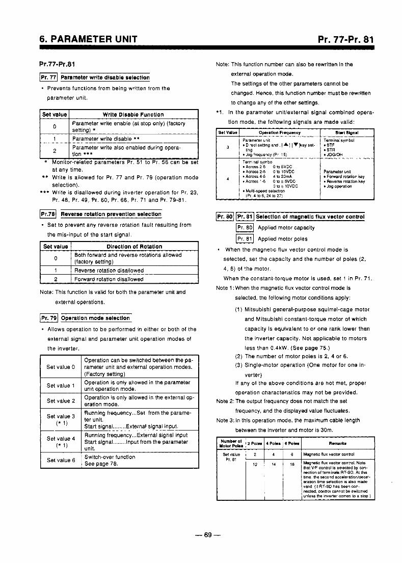
6. PARAMETER UNIT Pr. 77-Pr. 81
Pr.77-Pr.81
IPr. 771 Parameter write disable selectlon
Prevents functions from being written from the parameter unit.
Set value Write Dlsable Function ~~ ~~~ ~~~~~~~~~
Parameter write enable (at stop only) (factory setting) *
1 Parameter write disable ** Parameter write also enabled during opera- tion ***
* Monitor-related parameters Pr. 51 to Pr. 56 can be set at any time.
** Write is allowed for Pr. 77 and Pr. 79 (operation mode selection).
*** Write is disallowed during inverter operation for Pr. 23, Pr. 48, Pr. 49, Pr. 60, Pr. 66, Pr. 71 and Pr. 79-81.
IPr.781 Reverse rotation preventlon selection
Set to prevent any reverse rotation fault resulting from the mis-input of the start signal.
Set value Dlrectlon of Rotatlon Both forward and reverse rotations allowed (factory setting)
1 Reverse rotation disallowed
I 2 I Forward rotation disallowed I Note: This function is valid for both the parameter unit and
external operations.
IPr. 791 Operatlon mode selectlon
Allows operation to be performed in either or both of the external signal and parameter unit operation modes of the inverter. 1 Operation can be switched between the pa- Set value 0 rameter unit and external operation modes.
(Factory setting) Operation is only allowed in the parameter Set value ' unit ODeration mode. I I I I Set value 2 I Operation is only allowed in the external op- eration mode. I Running frequency ... Set from the parame-
Start signal ........ External signal input. I Set value 4 1 Running frequency ... External signal input ,* , , Start signal ........ Input from the parameter I
I Set value I See page 78. Switch-over function
Note: This function number can also be rewritten in the external operation mode. The settings of the other parameters cannot be changed. Hence, this function number must be rewritten to change any of the other settings.
*l. In the parameter univexternal signal combined opera- tion mode, the following signals are made valid:
set Value Start Signal Operation Frequency I Parameter unit
Direct setbng and , I A] I v ] k e y set-
Jcg frequency (Pr 15)
STF STR brig
Terminal symbo Across 2-5 0 to 5VDC Across 2-5 0 to lOVDC
*Across 4 5 410 20mA Across 1-5 0 to t 5VDC
Terminal symbol
JOQOH
Parameter unit Fornard rotation key
e Reverse rotation key Jog operation 0 tot lOVDC
Mu l t i - swd selection (Pr 4 to 6, 24 to 27)
1- I p I . 1 Selection of magnetic flux vector control
Applied motor capacity
Applied motor poles
When the magnetic flux vector control mode is selected, set the capacity and the number of poles (2, 4, 6) of the motor. When the constant-torque motor is used, set 1 in Pr. 71
Note 1 :When the magnetic flux vector control mode is
selected, the following motor conditions apply:
(1) Mitsubishi general-purpose squirrel-cage motor and Mitsubishi constant-torque motor of which capacity is equivalent to or one rank lower than the inverter capacity. Not applicable to motors less than 0.4kW. (See page 75.)
(2) The number of motor poles is 2, 4 or 6. (3) Single-motor operation (One motor for one in-
verter) If any of the above conditions are not met, proper operation characteristics may not be provided.
Note 2: The output frequency does not match the set frequency, and the displayed value fluctuates.
Note 3: In this operation mode, the maximum cable length between the inverter and motor is 30m.
S e t value Magnetic nux vector conlrol 6 4 2 Pr.81
14 Magnelc flux vector control. Note 16 hat VIF Conk01 is selected by con- nection of terminals RTSD. At this bme, me second accelerationfdecal- eration time selection is also made valid. (If RT-SD has been con-
I nected. Mntrol cannot be switched unless che inverter wmes to a stop ) I
- 69 -
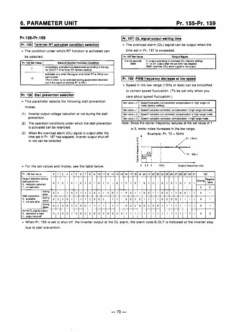
6. PARAMETER UNIT Pr. 155-Pr. 159
Pr.155-Pr.159 Termlnal RT actlvated condltlon selectlon
The condition under which RT function is activated can
be selected.
Pr. 155 S t Valuo Second Control Functbn Condttlon
0 Immediately achabed and deactivated accordng to the sig- nal ONIOFF of terminal RT (factow settino).
Activated only when me signal of terminal RT is ON at con- stant speed (The function is not activated during accaIeration/d8mlera- tion i f h e signal of terminal RT is ON.)
10
I p I . 1 Stail prevention selectlon
This parameter selects the following stall prevention
modes.
(1 ) Inverter output voltage reduction or not during the stall
(2) The operation conditions under which the stall prevention
(3) When the overload alarm (OL) signal is output after the time set in Pr. 157 has elapsed, inverter output shut-off or not can be selected.
prevention.
is activated can be restricted.
For the set values and modes, see the table below.
-1 OL signal output rmltlng time
The overload alarm (OL) signal can be output when the time set in Pr. 157 is exceeded.
i Pr. 157 Sol V d w output s(gMl 0 to 25 seconds 0 output acarding to overload (OL) (factory setting)
9989 0.1 to 25: outout a b r the set time hah elapsed.
[ P r . ] PWM frequency decrease at low speed
Speed in the low range (10Hz or less) can be smoothed
to correct speed fluctuation. (To be set only when you
care about speed fluctuation.)
I Sei Value = 0 I Speed fluctuation not corrected, comwnsation in high range not I I mode (factory s H n g ) .
comaensation in high range not made. I Set value = 1 1 Speed fluctuation corrected, .. . ' ' 'lighrangemade.
~~
S e t value = 2 S e t value = 3 Speed fluctuation corrected, compensation in high range made.
Speed fluctuation not corrected, compensanon In t
Note: Since the carrier frequency reduces at the set value of 1
or 3, motor noise increases in the low range. Example: Pr. 72 = 5kHZ
I, / Pr. 159=0
* 0 2 5 5 iOHz Output frequency (Hz)
When Pr. 156 is set to shut-off the inverter output at the OL alarm, the alarm code E.OLT is indicated at the inverter stop due to stall prevention.
- 70 -
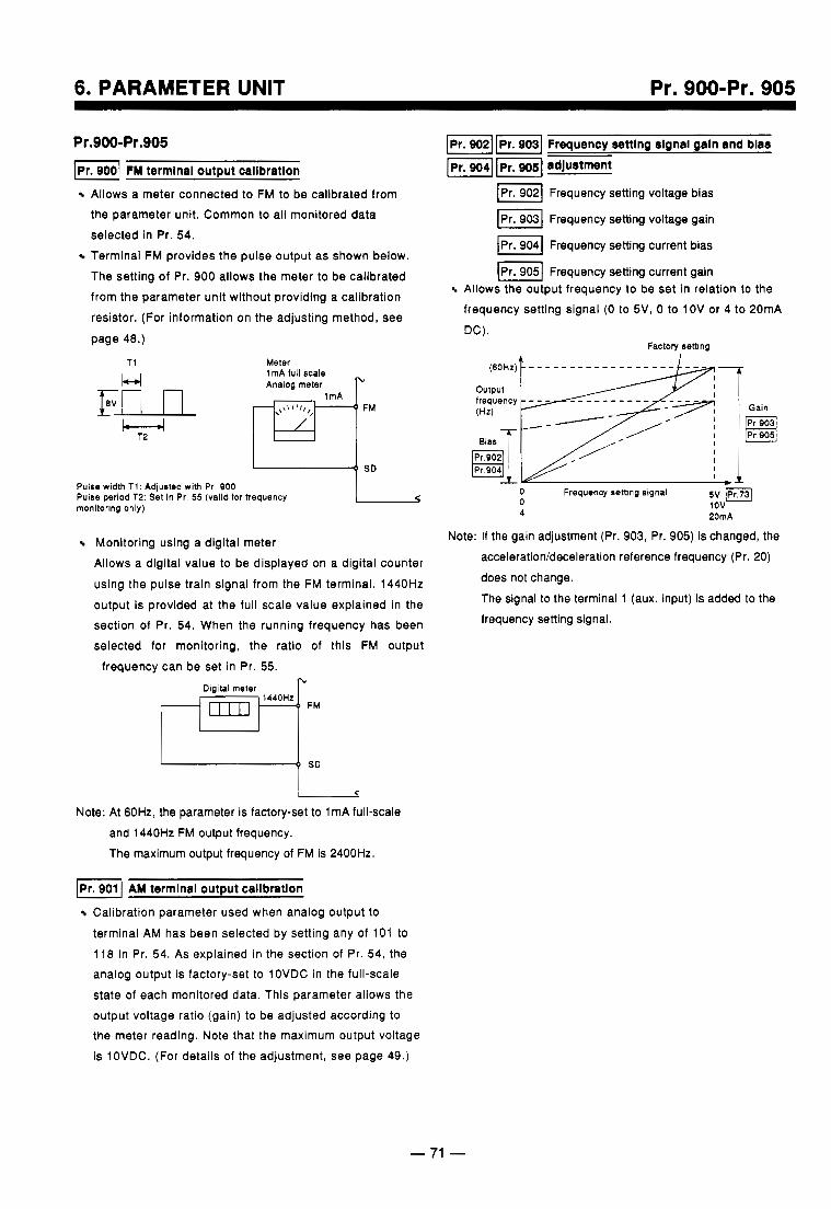
6. PARAMETER UNIT Pr. 900-Pr. 905
Pr.900-Pr.905 -1 FM terminal output callbration
Allows a meter connected to FM to be calibrated from the parameter unit. Common to all monitored data selected in Pr. 54. Terminal FM provides the pulse output as shown below.
The setting of Pr. 900 allows the meter to be calibrated from the parameter unit without providing a calibration resistor. (For information on the adjusting method, see
page 48.)
T i
M Meter
Analog meter I" 1mA full scale
Pulse width T i : Adjusted with Pr. 900 Pulse period T2: Set in Pr. 55 (valid for frequency monitoring only)
Monitoring using a digital meter Allows a digital value to be displayed on a digital counter using the pulse train signal from the FM terminal. 1440Hz output is provided at the full scale value explained in the section of Pr. 54. When the running frequency has been selected for monitoring, the ratio of this FM output
frequency can be set in Pr. 55. ?I
Digital meter 1440Hz
u FM
0 SD
C
Note: At 60Hz, the parameter is factory-set to 1 mA full-scale and 1440Hz FM output frequency. The maximum output frequency of FM is 2400Hz.
AM terminal output calibration
Calibration parameter used when analog output to
terminal AM has been selected by setting any of 101 to 118 in Pr. 54. As explained in the section of Pr. 54, the analog output is factory-set to 10VDC in the full-scale state of each monitored data. This parameter allows the output voltage ratio (gain) to be adjusted according to the meter reading. Note that the maximum output voltage is 10VDC. (For details of the adjustment, see page 49.)
Frequency setting signal galn and bias
I P r . 1 adlustrnnt
-1 Frequency setting voltage bias
IPr. 9031 Frequency setting voltage gain
IPr. 9041 Frequency setting current bias
[=I Frequency setting current gain Allows the output frequency to be set in relation to the frequency setting signal (0 to 5V, 0 to 1OV or 4 to 20mA
DC). Factory setting
output
(Hz)
0 Frequency setting signal
4 20mA 0
5v -m 1 ov
Note: If the gain adjustment (Pr. 903, Pr. 905) is changed, the acceleration/deceleration reference frequency (Pr. 20) does not change. The signal to the terminal 1 (aux. input) is added to the frequency setting signal.
-.
.
- 71 -
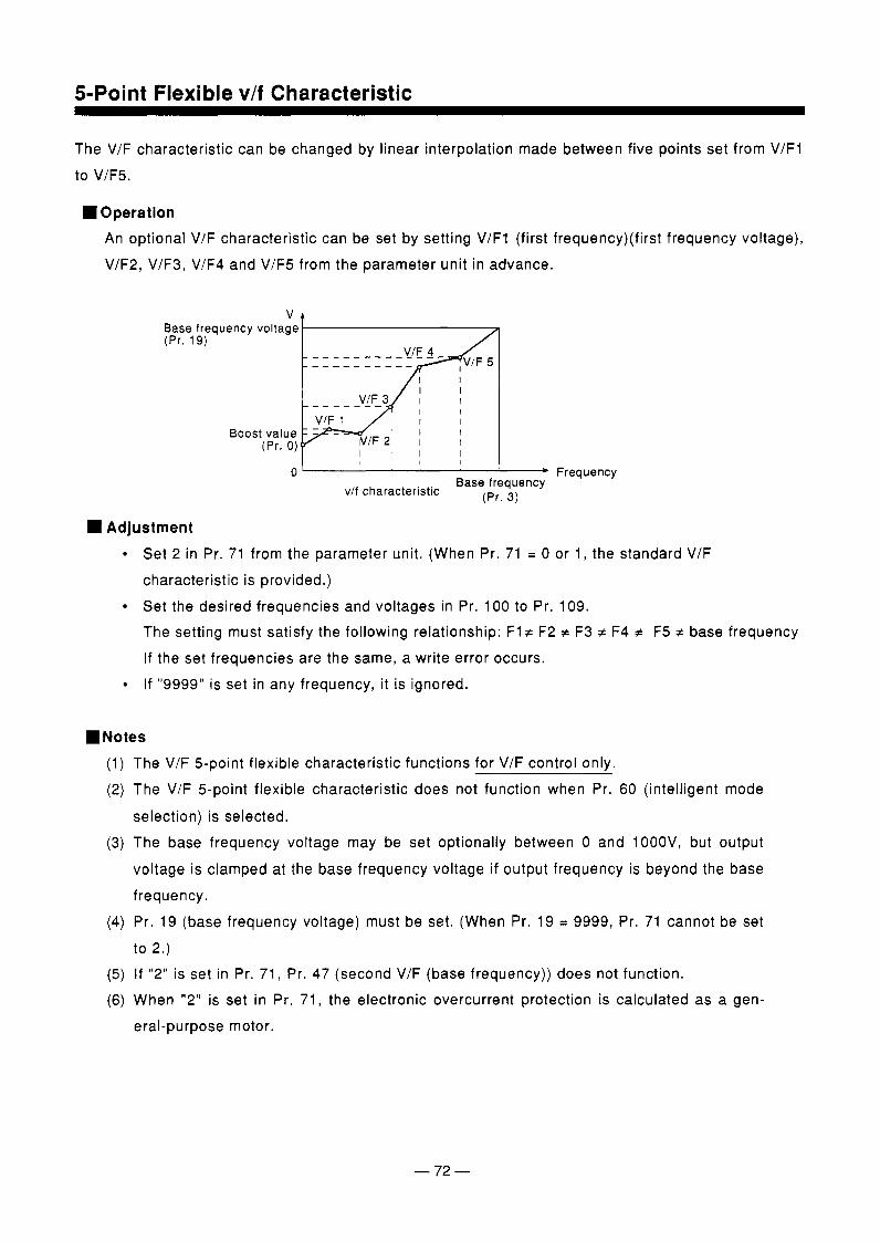
5-Point Flexible v/f Characteristic
The V/F characteristic can be changed by linear interpolation made between five points set from V/F1 to V/F5.
H Operation An optional V/F characteristic can be set by setting V/F1 (first frequency)(first frequency voltage), V/F2, V/F3, V/F4 and V/F5 from the parameter unit in advance.
I I
I I Boost value I I
(Pr. 0) I I I
I l l I
* Frequency v/f characteristic Base frequency
(Pr. 3)
Adjustment Set 2 in Pr. 71 from the parameter unit. (When Pr. 71 = 0 or 1, the standard V/F characteristic is provided.) Set the desired frequencies and voltages in Pr. 100 to Pr. 109. The setting must satisfy the following relationship: F l z F2 f F3 z F4 f F5 z base frequency If the set frequencies are the same, a write error occurs. If "9999" is set in any frequency, it is ignored.
Notes The V/F 5-point flexible characteristic functions for V/F control only. The V/F 5-point flexible characteristic does not function when Pr. 60 (intelligent mode
selection) is selected. The base frequency voltage may be set optionally between 0 and lOOOV, but output
voltage is clamped at the base frequency voltage if output frequency is beyond the base frequency. Pr. 19 (base frequency voltage) must be set. (When Pr. 19 = 9999, Pr. 71 cannot be set to 2.) If "2" is set in Pr. 71, Pr. 47 (second V/F (base frequency)) does not function. When "2" is set in Pr. 71, the electronic overcurrent protection is calculated as a gen- eral-purpose motor.
- 72 -
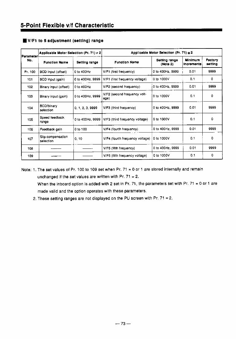
5-Point Flexible vlf Characteristic
VIF1 to 5 adjustment (setting) range
1 Armllcable Motor Selection (Pr. 71) # 2 Appllcable Motor Selectlon (Pr. 71) 2 Parameter 1 NO.
. . . .
Functlon Name Functlon Name Settlng range Settlng range Increments (Note 2)
Factory Mlnlmum settlng
Pr. 100
9999 0.01 0 to 400Hz, 9999 V/F2 (second frequency) 0 to 400Hz Binary input (offset) 102
0 0.1 0 to lOOOV V/F1 (first frequency voltage) 0 to 400Hz, 9999 BCD input (gain) 101
9999 0.01 0 to 400Hz, 9999 V/F1 (first frequency) 0 to 400Hz BCD input (offset)
I 103 I Binary input (gain) IO to 400Hz, 9999 VIF2 (second frequency volt- to looov 1 0.1 I 0
I lo4 I BCDhinary selection IO, 1, 2, 3, 9999 1 V/F3 (third frequency) IO to 400Hz, 9999 I 0.01 1 9999
lo5
9999 0.01 0 to 400Hz, 9999 V/F4 (fourth frequency) 0 to 100 Feedback gain 106
range Speed feedback 0 0.1 0 to lOOOV V/F3 (third frequency voltage) 0 to 400Hz, 9999
I lo' I Slip compensation o, selection
I V/F4 (fourth frequency voltage) 10 to lOOOV I 0.1 1 0
108 - 9999 0.01 0 to 400Hz,9999 V/F5 (fifth frequency)
109 0 0.1 0 to lOOOV V/F5 (fifth frequency voltage)
Note: 1. The set values of Pr. 100 to 109 set when Pr. 71 = 0 or 1 are stored internally and remain unchanged if the set values are written with Pr. 71 = 2. When the inboard option is added with 2 set in Pr. 71, the parameters set with Pr. 71 = 0 or 1 are made valid and the option operates with these parameters.
2. These setting ranges are not displayed on the PU screen with Pr. 71 = 2.
- 73 -
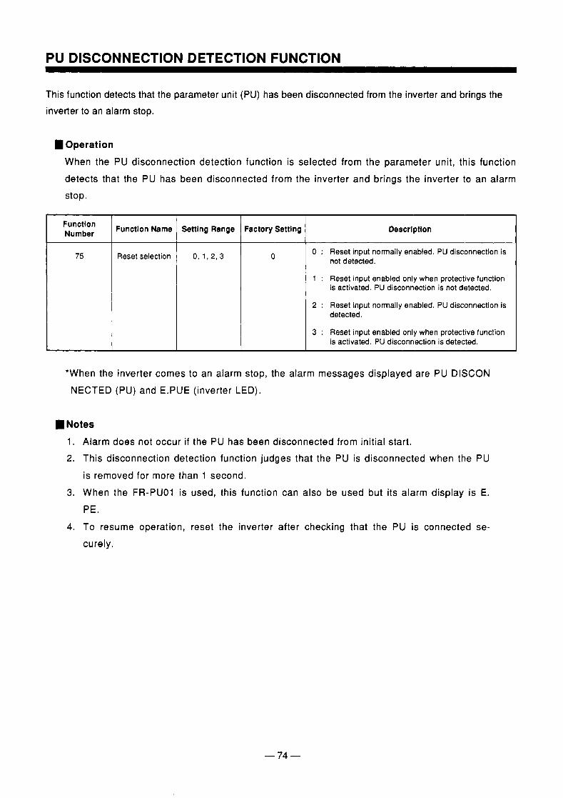
PU DISCONNECTION DETECTION FUNCTION
This function detects that the parameter unit (PU) has been disconnected from the inverter and brings the inverter to an alarm stop.
I Operation When the PU disconnection detection function is selected from the parameter unit, this function detects that the PU has been disconnected from the inverter and brings the inverter to an alarm stop.
Function Number
75
Function Name Settlng Range Factory Setting Descrlptlon I Reset selection 0, 1, 2, 3 0 0 : Reset input normally enabled. PU disconnection is
not detected.
1 : Reset input enabled only when protective function is activated. PU disconnection is not detected.
2 : Reset input normally enabled. PU disconnection is detected.
3 : Reset input enabled only when protective function is activated. PU disconnection is detected.
*When the inverter comes to an alarm stop, the alarm messages displayed are PU DISCON NECTED (PU) and E.PUE (inverter LED).
I Notes 1. Alarm does not occur if the PU has been disconnected from initial start. 2. This disconnection detection function judges that the PU is disconnected when the PU
is removed for more than 1 second. 3. When the FR-PUO1 is used, this function can also be used but its alarm display is E.
PE. 4. To resume operation, reset the inverter after checking that the PU is connected se-
curely.
- 74 -
MAGNETIC FLUX VECTOR CONTROL
Selection of Magnetic Flux Vector Control Magnetic flux vector control can be selected by setting the capacity, number of poles, and type of the motor used.
Conditions for selecting magnetic flux vector control Only when the following conditions are met, magnetic flux vector control can be utilized efficiently. When any of the following conditions cannot be satisfied, faults such as torque shortage and speed fluctuation may occur. In this case, select V/F control.
The motor capacity is equal to or one rank lower than the inverter capacity. Note that the motor capacity must be 0.4kW or more. The type of the motor is the Mitsubishi standard motor or Mitsubishi constant-torque motor or the U.S. Baldor's 400V series inverter-duty motor. The number of motor poles is any of 2, 4 and 6. Single-motor operation (one motor for one inverter) is performed. The wiring length between the inverter and motor is within 30m.
Magnetic flux vector control selection method Only set any other values than 9999 in Pr. 80 (motor capacity) and Pr. 81 (number of poles) to se- lect the magnetic flux vector control. When 9999 has been set to either of Pr. 80 and Pr. 81, V/F control is selected. When the Mitsubishi constant-torque motor is used, set 1 in Pr. 71.
By switching on/off the signal across terminals RT-SD, operation can be switched between the V/F control and magnetic flux vector control.
(Note) The magnetic flux vector control is available for the U.S. Baldor's 400V series inverter- duty motor when any of 0.75 to 55kw is set in Pr. 80 and 4 is set in Pr. 81 for the A200 US version 400V series inverter.
In the following cases, this function is available only for the Mitsubishi standard motor. 0 The 200V series 0 For the 400V series inverter, 0.4kw is set in Pr. 80 or 2 or 6 is in Pr. 81. For motors other than the listed above, please contact your Mitsubishi representative.
Precautions for magnetic flux vector control The degree of speed fluctuation correction is slightly lower than in the V/F control. There is a delay of 0.1 to 0.2sec at start. Applications appropriate for magnetic flux vector control Machines which require large starting torque Machines which require enough torque at low speed Machines where load fluctuates widely Applications inappropriate for magnetic flux vector control Machines where speed fluctuation at low speed is not allowed, e.g. grinder, wrapping machine.
- 75 -
..".
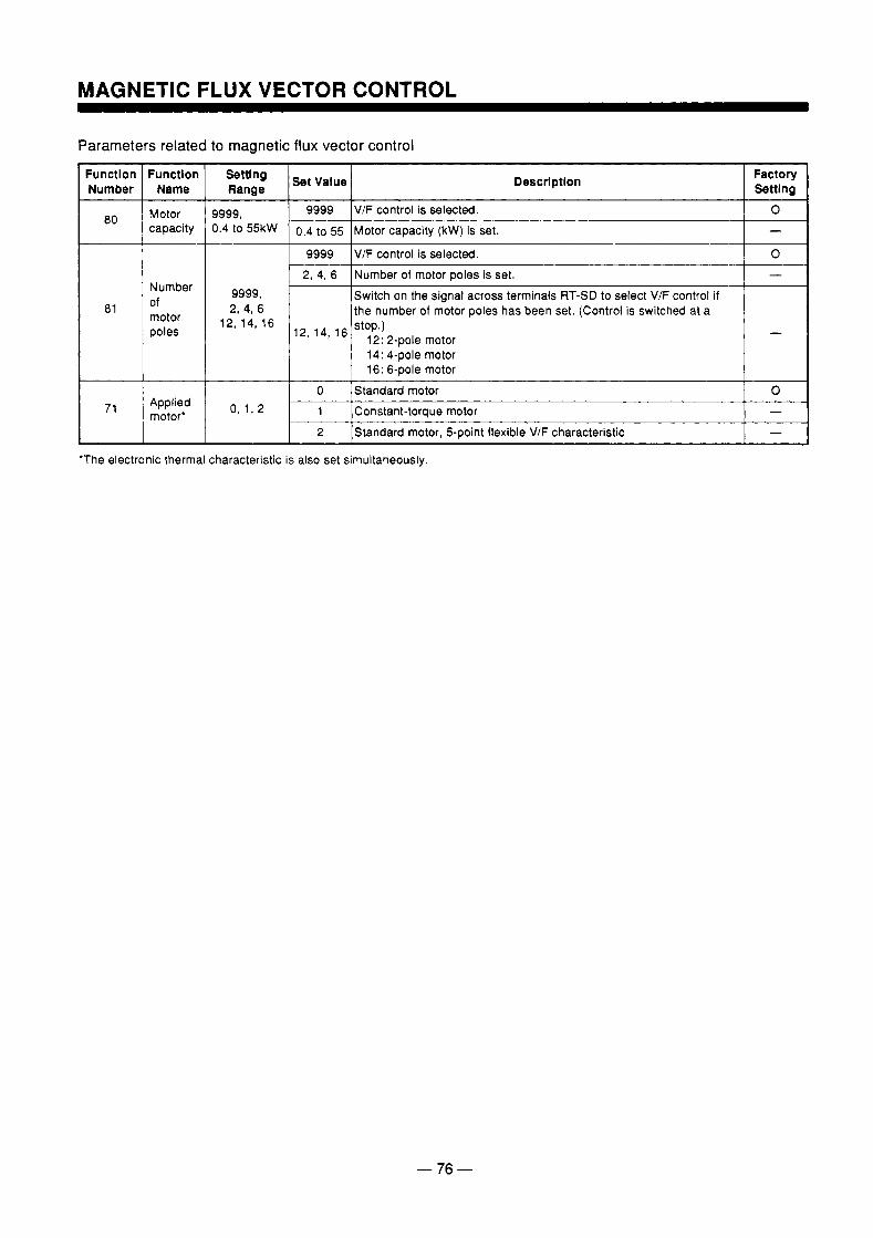
Parameters related to magnetic flux vector control
Function Number
80
81
71
Function Name
Motor capacity
Number of motor poles
Applied motor'
Settl ng Range
9999, 0.4 to 55kW
9999, 2, 4, 6
12, 14, 16
Descrlptlon
9999 V/F control is selected.
0.4 to 55 Motor capacity (kW) is set.
9999 V/F control is selected.
-
-
2, 4, 6 [Number of motor poles is set. Switch on the signal across terminals RT-SD to select VIF control if the number of motor poles has been set. (Control is switched at a
14: 4-pole motor 16: 6-pole motor
0 /Standard motor 1 Constant-torque motor 2 Standard motor, 5-point flexible V/F characteristic
'The electronic thermal characteristic is also set simultaneously.
Factory Settlng
0
0
- 76 -
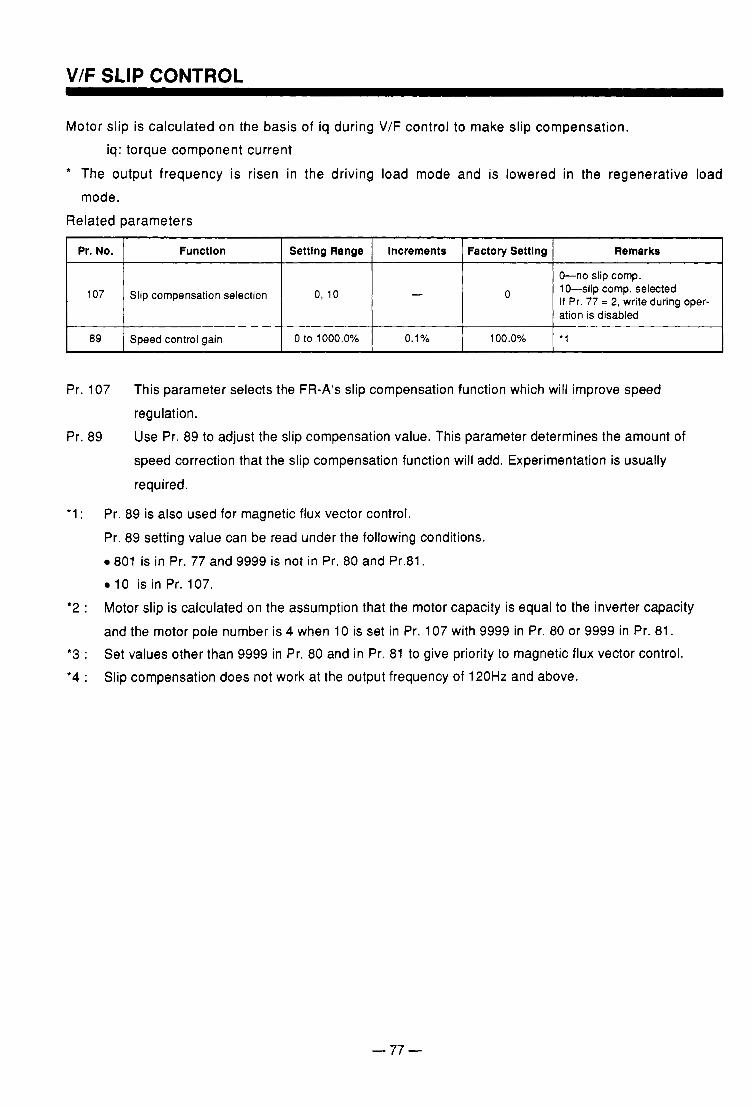
V/F SLIP CONTROL
Motor slip is calculated on the basis of iq during V/F control to make slip compensation. iq: torque component current
+ The output frequency is risen in the driving load mode and is lowered in the regenerative load mode.
Related parameters
I Pr. NO. I Function I Settlng Range I increments I Factory Settlng I Remarks I I I I I I
I I
107 0, 10 Slip compensation selection 0 O-no slip cornp. 10-slip cornp. selected If Pr. 77 = 2, write during oper- ation is disabled
I I I I I 89 '1 100.0% 0.1 o/o 0 to 1000.0~/0 Speed control gain
~~ ~ ~~~
Pr. 107 This parameter selects the FR-A's slip compensation function which will improve speed regulation.
Pr. 89 Use Pr. 89 to adjust the slip compensation value. This parameter determines the amount of speed correction that the slip compensation function will add. Experimentation is usually
required.
'1 : Pr. 89 is also used for magnetic flux vector control. Pr. 89 setting value can be read under the following conditions.
801 is in Pr. 77 and 9999 is not in Pr. 80 and Pr.81. 10 is in Pr. 107.
'2 : Motor slip is calculated on the assumption that the motor capacity is equal to the inverter capacity and the motor pole number is 4 when 10 is set in Pr. 107 with 9999 in Pr. 80 or 9999 in Pr. 81.
*3 : Set values other than 9999 in Pr. 80 and in Pr. 81 to give priority to magnetic flux vector control. *4 : Slip compensation does not work at the output frequency of 120Hz and above.
- 77 -
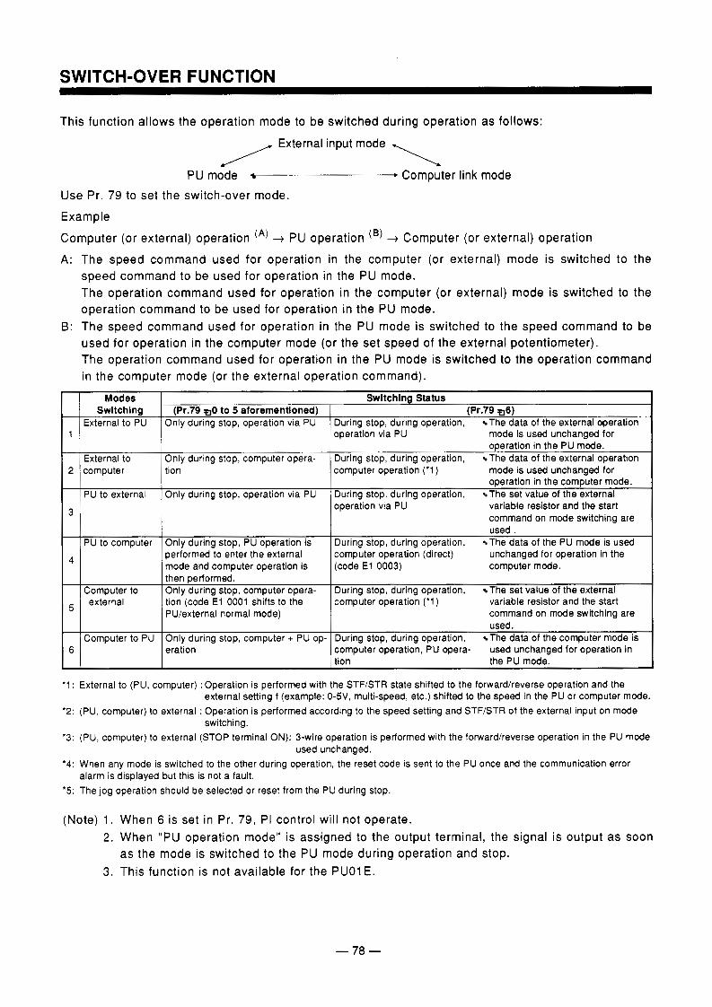
A:
B:
This function allows the operation mode to be switched during operation as follows:
External input mode \ PU mode . Computer link mode
Use Pr. 79 to set the switch-over mode. Example
Computer (or external) operation (*) + PU operation (B) + Computer (or external) operation The speed command used for operation in the computer (or external) mode is switched to the speed command to be used for operation in the PU mode. The operation command used for operation in the computer (or external) mode is switched to the operation command to be used for operation in the PU mode. The speed command used for operation in the PU mode is switched to the speed command to be used for operation in the computer mode (or the set speed of the external potentiometer). The operation command used for operation in the PU mode is switched to the operation command in the computer mode (or the external operation command).
Modes Swltchlng Status Swltchlng (Pr.79 6) (Pr.79 0 to 5 atorementloned)
External to PU During stop, during operation, The data of the external operation Only during stop, operation via PU 1 operation via PU mode is used unchanaed for
operation in the PU mode. I External to I Only during stop, computer opera- I During stop, during operation, The data of the external Operation
2
operation via PU variable resistor and the start During stop, during operation, The set value of the external Only during stop, operation via PU PU to external
computer operation ('1) mode is used unchanged for tion computer operation in the computer mode.
3 command on mode switching are used .
PU to computer Only during stop, PU operation is During stop, during operation, The data of the PU mode is used performed to enter the external
(code E l 0003) computer mode. mode and computer operation is computer operation (direct) unchanged for operation in the 4
I then performed. I Comauter to I Onlv durina stop, comwter opera- I During stop, during operation, The set value of the external
external t io i (codeE1 0001 shifts to the PU/external normal mode)
compiter operation ('1 ) variable resistor and the start command on mode switching are
~~
used. '
computer operation, PU opera- used unchanged for operation in eration 6 During stop, during operation, The data of the computer mode is Only during stop, computer + PU op- Computer to PU
tion the PU mode.
'1 : External to (PU, computer) :Operation is performed with the STF/STR state shifted to the forwardheverse operation and the
'2: (PU, computer) to external : Operation is performed according to the speed setting and STF/STR of the external input on mode
'3: (PU, computer) to external (STOP terminal ON): 3-wire operation is performed with the forwardireverse operation in the PU mode
'4: When any mode is switched to the other during operation, the reset code is sent to the PU once and the communication error
'5: The jog operation should be selected or reset from the PU during stop.
external setting f (example: 0-5V, multi-speed, etc.) shifted to the speed in the PU or computer mode.
switching.
used unchanged.
alarm is displayed but this is not a fault.
(Note) 1. When 6 is set in Pr. 79, PI control will not operate. 2 . When "PU operation mode" is assigned to the output terminal, the signal is output as soon
3. This function is not available for the PUO1 E. as the mode is switched to the PU mode during operation and stop.
- 78 -
7. MAINTENANCE AND INSPECTION
The transistorized inverter is a static unit consisting mainly of semiconductor devices. Daily inspection must be performed to prevent any fault from occurring due to adverse influence by the installation environment, such as temperature, humidity, dust, dirt and vibration, changes in the parts with time, service life, and other factors.
7.1 Precautions for Maintenance and Inspection (1) The operator must check power on/off by himself to prevent any person not in charge from
misoperating the inverter.
(2) For some short time after the power is switched off, the capacitor remains charged at a high voltage. Before performing any inspection, make sure that the charge lamp on the printed circuit is off and check that the voltage across the main circuit terminals P and N of the inverter is 3OVDC or less using a tester, etc. (For the location of the charge lamp, see the terminal block
arrangement on page 106.)
7.2 Check Items Have a proper understanding of the definitions of power and alarm indications provided for the inverter. Also, have a proper understanding of the settings of electronic overcurrent protection, etc.
(1) Daily inspection Check for the following:
(a) Motor operation fault (b) Improper installation environment (c) Cooling system fault
(d) Unusual vibration and noise (e) Unusual overheat and discoloration
During operation, check the inverter voltages using a tester.
(2) Periodic maintenance and inspection Check the areas inaccessible during operation and requiring periodic inspection.
(a) Cooling system: Clean the air filter, etc. (b) Screws and bolts: Check that they are se-
curely tightened and retighten as neces- sary.
I/O (c) Conductors and insulating materials: Check for corrosion and damage.
(d) Insulation resistance: 'Measure.
(e) Cooling fan, smoothing capacitor, relay: Check and change if necessary.
- 79 -
. . ..
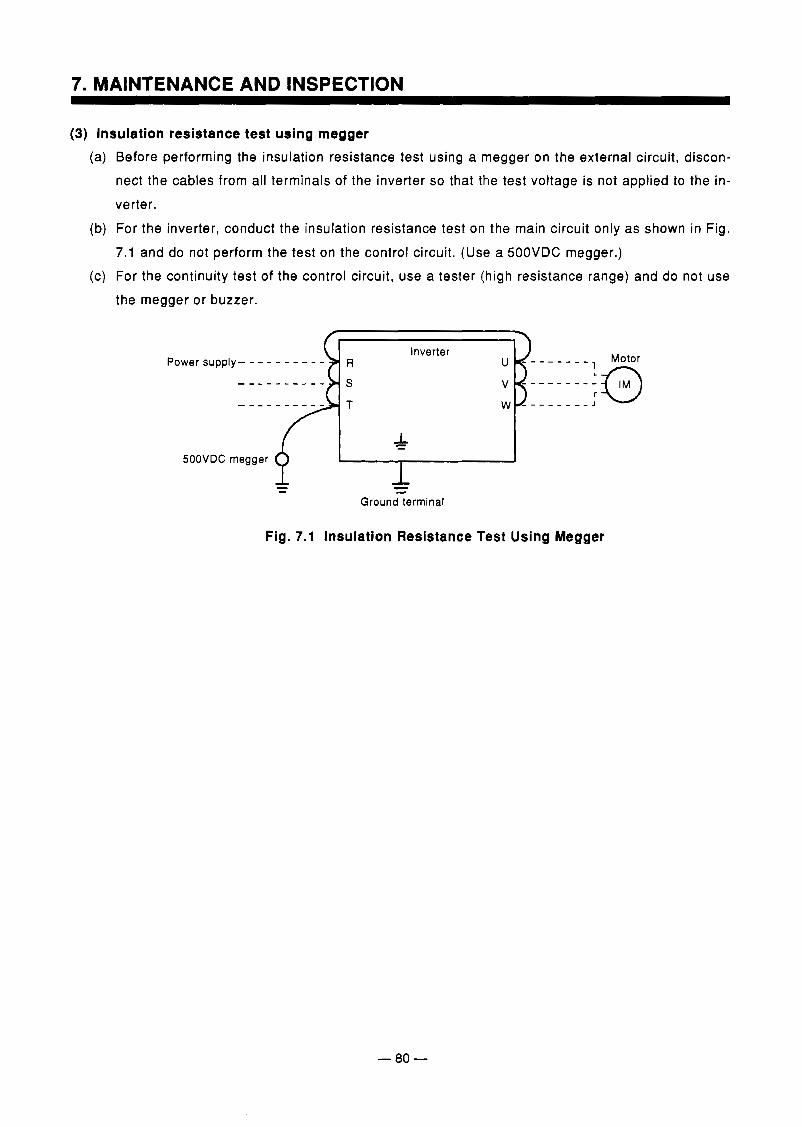
7. MAINTENANCE AND INSPECTION
(3) Insulation resistance test using megger (a) Before performing the insulation resistance test using a megger on the external circuit, discon-
nect the cables from all terminals of the inverter so that the test voltage is not applied to the in- verter.
(b) For the inverter, conduct the insulation resistance test on tha main circuit only as shown in Fig. 7.1 and do not perform the test on the control circuit. (Use a SOOVDC megger.)
( c ) For the continuity test of the control circuit, use a tester (high resistance range) and do not use the megger or buzzer.
Power supply- - - - - - - -
SOOVDC megger
- Ground terminal
Motor
Fig. 7.1 Insulation Resistance Test Using Megger
- 80 -
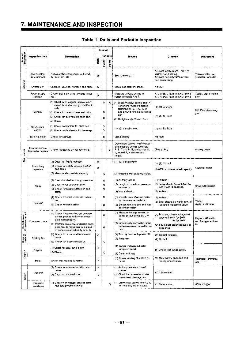
/ / / 1 Ambient temperature: -lO'C to I I o ~ 1 1 S e e m t e o n p . 7 . +~o*c, nowieering.
Ambient humidity 90% or less, grometw, recorder I Thermometer, hy- I
non-condensing
0 No fault. Visual and auditory check
verter terminals R-S-T. Measure voltage across in- 170 to 253V (323 to 506'4) 50Hz Tester, digital multim-
170 to 242V (323 to 506V) 60Hz eter I (1) Check with megger (across mam
circuit terminals and ground termi- nal).
General (2) Check for loose screws and b l k . (3) Check for overheat on each part (4) Clean.
c ~ ~ ~ ~ ~ ~ ~ ~ , (I) Check conductors for distortion cables (2) Check cable sheaths for breakage.
I Check for damage Terminal block
0 (1) Disconnect all caMes lrom in- 0 verter and measwe aaoss
0
5M or terrnlmls R, S, T, U, V. W and ground terminal with meg- ger.
(2) Retighten (3) Visual check. (2), (3) No fault
I 0
(l), (2) Vlsual check. ( I ) , (2) No fault
0 No fault Visual check
and measure across terminals Disconnect cables from inverter
V, Wand P. N with tester x 1 range
o Analog tester ( S e e p 84 ) R, S, T and P, N, and across U.
.- 9 (1) Check for liquid leakage.
Smoothing (2) Check for safety valve prolectlon capacltw and bulge.
(3) Measure electrwtatlc capacity
( I ) Check for chatter dunng operabon (2) Check timer operation time (3) Check for rough surface on w n -
Relay
tack.
(1) Check for crack in resistor insula-
0 I 1 I (I), (2)Visual check
O I 1 I 0 I (3) Measure wlth capacity meter
0 (1) Auditwy check. (1) No fault (2) Length of time from power on (2) Relay should be swiMed on
in0.l toO.15seconds Universal counmr I (3) Visual check. (3) No fault.
0 (1) Visual c h d . Cement resis- (1) No fault.
0 (2) Disconnect one end and mea- indicated resistance value.
tor, wire-wound resistor.
sure with tester. di9iQl multimeter
(2) Error should be within 10% of Tester, (2) Check for open cable I
Check balance of output voltages across phases with Inverter oper- ated independenb'y
ation test to make sure of no fault Perform sequence protective oper.
In protective and display circuits. (1) Check for unusual vibration and
(2) Check for loose connection.
(1) Check for LED lam^ blown
Cooling fan mise.
0 (1) Lamps indicate indicator
(2) Clean with r a g
(1) Check reading of meters on (1) Must satisfy specified and voltmeter, ammeter,
lamps on panel. ( 1 ) Check that lamps are lit.
0 1 panel. managementvalues. etc. Check that reading is normal
(1) Check for unusual vlbrabon and
(2) Check for unusual odor. General
resistance nals and ground terminal)
1 1 1 I I
0 I I I ( 1 ) Auditory, sensory, visual I - I ~ 1 ' ' tooverheat, damwe, etc I I I
1 i I W, lncludlog motorcables. ~ ( I ) 5M Or more (1) Disconnect cables lrom U, V,
- 81 -
.. . .
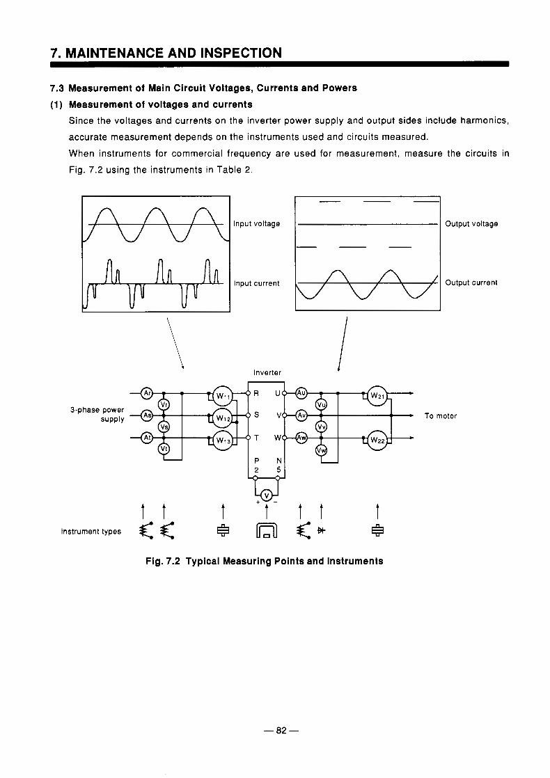
7. MAINTENANCE AND INSPECTION
7.3 Measurement of Main Circuit Voltages, Currents and Powers (1) Measurement of voltages and currents
Since the voltages and currents on the inverter power supply and output sides include harmonics, accurate measurement depends on the instruments used and circuits measured. When instruments for commercial frequency are used for measurement, measure the circuits in Fig. 7.2 using the instruments in Table 2.
n n n
3-phase power supply
- Input voltage Output voltage
-
Input current Output current
Inverter 1 U I P
U
V
W
N
L@J t t t + t - t T t
Instrument types +x H
To motor
Fig. 7.2 Typical Measuring Points and Instruments
- 82 -
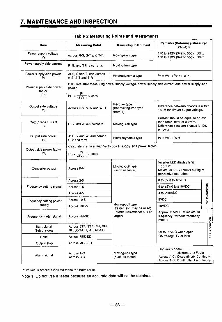
Table 2 Measuring Points and Instruments
Item
Power supply voltage v1
Power supply side current I1
Power supply side power P1
Power supply side power factor
Pfl
Output side voltage v2
Output side current 12
Output side power P2
Output side power factor Pf2
Converter output
Frequency setting signal
Frequency setting power supply
Frequency meter signal
Start signal Select signal
Reset
output stop
Alarm signal
Measuring Polnt I Measurlng Instrument I Remarks (Reference hbasured Value) *
Across R-S, S-T and T-R Moving-iron type 170 to 242V (342 to 506V) 50Hz 170 to 253V (342 to 506V) 60Hz
R, S, and T line currents I Moving-iron type I
Calculate after measuring power supply voltage, power supply side current and power supply side power.
Pfl = T i z p1 x10046
Rectifier type
(note 1 ) Across U-V, V-W and W-U (not moving-iron type) Difference between phases is within
1% of maximum output voltage.
U, V and W line currents Moving-iron type
Current should be equal to or less than rated inverter current. Difference between phases is 10% or lower.
At U, V and W, and across Electrodynamic type U-V and V-W P2 = w2i + w 2 2
I I
Calculate in similar manner to power supply side power factor.
Pf2 = 5 Z - G p2 x 100%
Across P-N Movingcoil type (such as tester)
~
Across 2-5 I
Across 4-5
Across 10-5
Across 1 OE-5 Movingcoil type (Tester, etc. may be used)
Across FM-SD (Internal resistance: 50k or larger)
RL, JOG/OH, RT, AU-SD
Across A-C Across B-C
Movingcoil type (such as tester)
* Values in brackets indicate those for 400V series.
Note 1 : Do not use a tester because an accurate data will not be obtained.
- 83 -
Inverter LED display is lit. 1.35 x V1 Maximum 380V (760V) during re- generative operation
0 to 5V/O to 10VDC
0 to rt5V/O to fl OVDC
4 to 20mADC
c
E E 8
5 v) .-
lOVDC
Approx. 3.5VDC at maximum
20 to BOVDC when open ON voltage 1 V or less
/ Continuity check
Across A-C: Discontinuity Continuity Across B-C: Continuity Discontinuit)
<Normal> Fault>
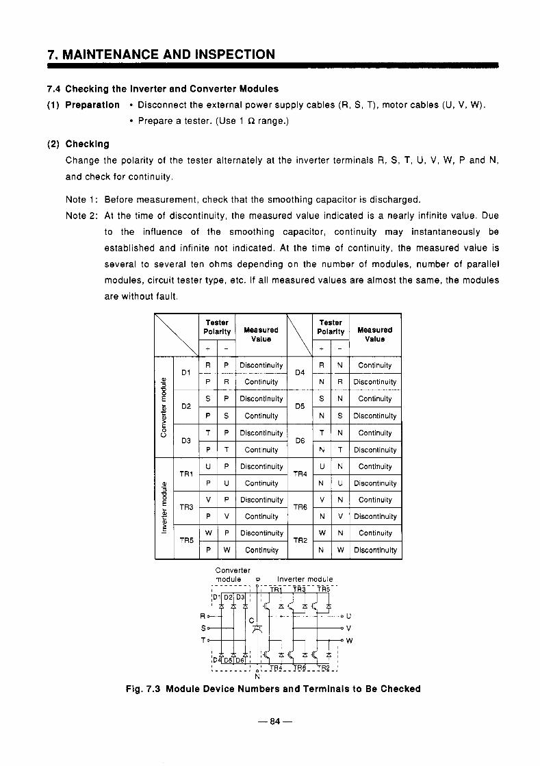
7. MAINTENANCE AND INSPECTION
Checking the Inverter and Converter Modules Preparation Disconnect the external power supply cables (R, S , T), motor cables (U, V, W).
Prepare a tester. (Use 1 R range.)
Checking Change the polarity of the tester alternately at the inverter terminals R, S , T, U, V, W, P and N, and check for continuity.
Note 1 : Before measurement, check that the smoothing capacitor is discharged. Note 2: At the time of discontinuity, the measured value indicated is a nearly infinite value. Due
to the influence of the smoothing capacitor, continuity may instantaneously be established and infinite not indicated. At the time of continuity, the measured value is several to several ten ohms depending on the number of modules, number of parallel modules, circuit tester type, etc. If all measured values are almost the same, the modules are without fault.
Converter module p Inverter module
N Fig. 7.3 Module Device Numbers and Terminals to Be Checked
- 84 -
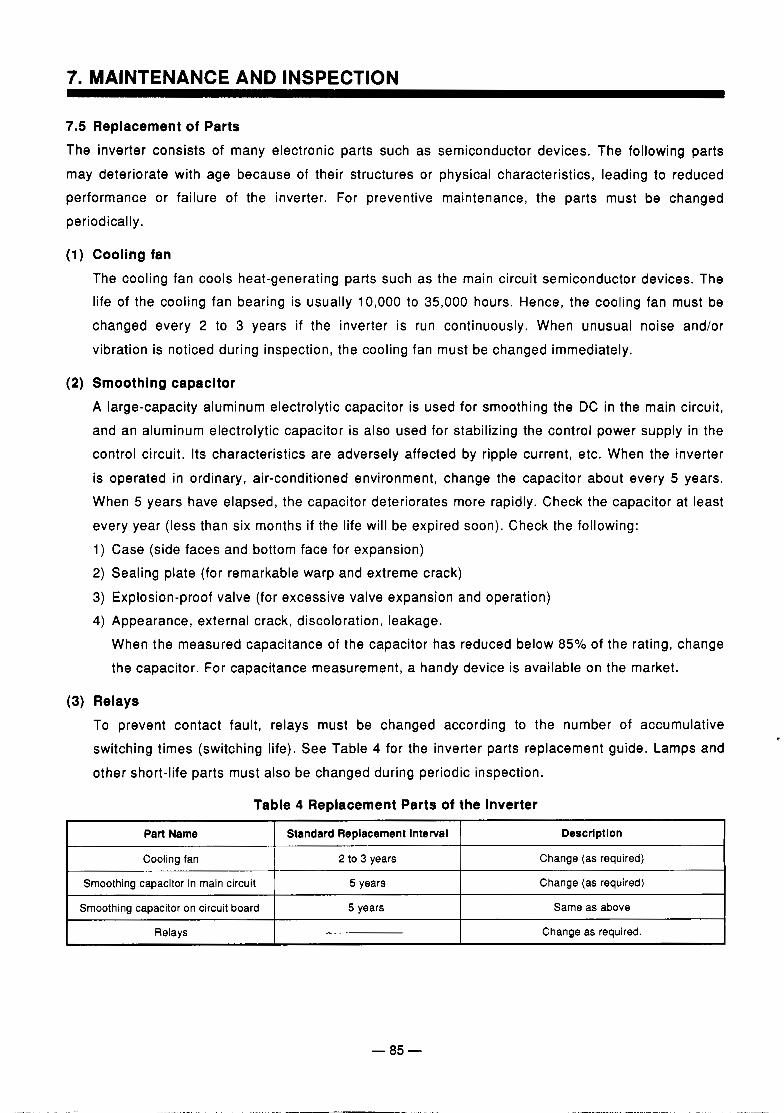
7. MAINTENANCE AND INSPECTION
7.5 Replacement of Parts The inverter consists of many electronic parts such as semiconductor devices. The following parts
may deteriorate with age because of their structures or physical characteristics, leading to reduced performance or failure of the inverter. For preventive maintenance, the parts must be changed periodically.
(1) Cooling fan The cooling fan cools heat-generating parts such as the main circuit semiconductor devices. The life of the cooling fan bearing is usually 10,000 to 35,000 hours. Hence, the cooling fan must be changed every 2 to 3 years if the inverter is run continuously. When unusual noise and/or vibration is noticed during inspection, the cooling fan must be changed immediately.
(2) Smoothing Capacitor A large-capacity aluminum electrolytic capacitor is used for smoothing the DC in the main circuit, and an aluminum electrolytic capacitor is also used for stabilizing the control power supply in the control circuit. Its characteristics are adversely affected by ripple current, etc. When the inverter is operated in ordinary, air-conditioned environment, change the capacitor about every 5 years. When 5 years have elapsed, the capacitor deteriorates more rapidly. Check the capacitor at least every year (less than six months if the life will be expired soon). Check the following: 1) Case (side faces and bottom face for expansion) 2) Sealing plate (for remarkable warp and extreme crack)
3) Explosion-proof valve (for excessive valve expansion and operation) 4) Appearance, external crack, discoloration, leakage.
When the measured capacitance of the capacitor has reduced below 85% of the rating, change the capacitor. For capacitance measurement, a handy device is available on the market.
(3) Relays To prevent contact fault, relays must be changed according to the number of accumulative switching times (switching life). See Table 4 for the inverter parts replacement guide. Lamps and
other short-life parts must also be changed during periodic inspection.
Table 4 Replacement Parts of the Inverter
1 Part Name 1 Standard Replacement Interval I Descrlptlon I ~~
Cooling fan
Change (as required) 5 years Smoothing capacitor in main circuit
Change (as required) 2 to 3 years
Smoothing capacitor on circuit board Same as above 5 years
Relays Change as required.
- 85 -
. . .
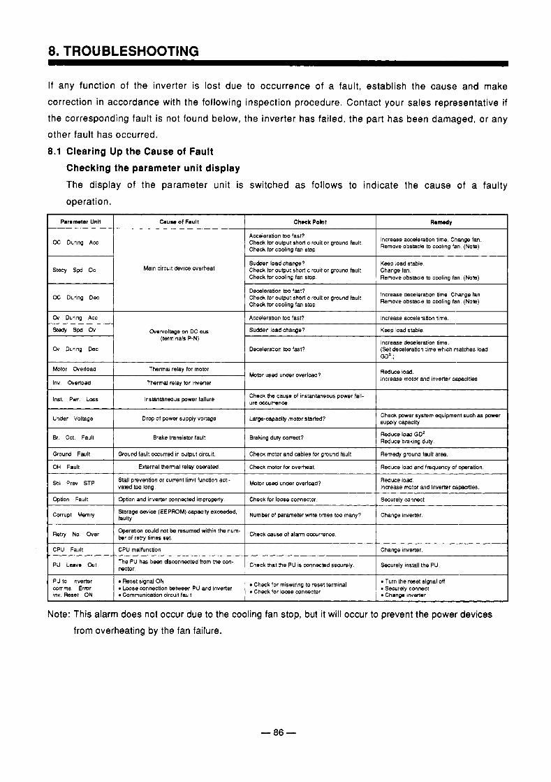
8. TROUBLESHOOTING
If any function of the inverter is lost due to occurrence of a fault, establish the cause and make correction in accordance with the following inspection procedure. Contact your sales representative if the corresponding fault is not found below, the inverter has failed, the part has been damaged, or any other fault has occurred. 8.1 Clearing Up the Cause of Fault
Checking the parameter unit display The display of the parameter unit is switched as follows to indicate the cause of a faulty operation.
Cheek Polnt Remedy
Acceleration too fast? Check for output short c i rwi tor ground fault. ~~~,B~~~~~~~~zze,g","n~o~, Chedc for coding fan stop.
OC During Acc
st* spd o c Main circult devlce overheat Sudden load change? Keep load stable. Check for output short circuit or ground fault Change fan, Check for coding fan stop. Remove obstacle to cooling fan. (Note)
Deceleration too fast?
Check for coding fan stop. Check for output short circuit or ground fault. ~ ~ ~ ~ ~ ~ ~ ~ s ~ ~ ~ ~ B ~ a ~ ~ ~ o ~ ; OC During Dec
stedy spd ov Overvoltage on DC bus (terminals P-N)
Or During Dec
Sudden load change? Keep load stable.
Deceleration too fast? (Se t deceleration time which matches load
Motor Ovedoad
Thermal relay for inverter Inv Overload
Thermal relay for motor Motor used under overload? Reduce lord.
Increase motor and inverter capacities
lnst. Pwr. Loss Instantaneous power failure Check b e cause of instantaneous power fail- ure occurrence
Under Voltage I Drop of power supply voltage Large-capaaty motor started? Check power system equipment such as power supply capacity
~ ~~~
&. Cct. Fault I Brake tramistor fault 1 Braking duty correct? Reduce load GD'. Reduce braking duty
Ground Fault I Q o u r d fault occurred in output circuit. I Check motor and cables for ground fault. I Remedy ground fault area
OH Fault Reduce load and frequency of operation. Check motor for overheat. External h e m a l relay operated.
Stll Prev STP Stall prevention or current limit funcbon acti- I vated too long, Motor us& under overload? Reduce lord. Increase motor and inverter capacities
I I I
Option Fault 1 Option and inverter mnnected improperly. 1 Check for loose connector. Securely connect.
Memry Storage devica (EEPROM) capadty exceeded, I faulty Number of parameter write times too many? Change inverter.
Retry No h e r 1 Operatim could not be resumed within t h e num- ber of r e m times set. Check cause of alarm occurrence.
CPU Fault Change inverter. CPU malfunction
Check mat me PU is mnnecmd securely. ~ Securely install the PU
PU to Inverter mmms. Error
Reset signal ON
Change inverter Communication clrcuit fault Inv. Reset ON . Check for mnnector Loose connection between PU and inverter Check for miswiring to reset terminal Turn the reset signal off Securely connect
Note: This alarm does not occur due to the cooling fan stop, but it will occur to prevent the power devices from overheating by the fan failure.
- 86 -
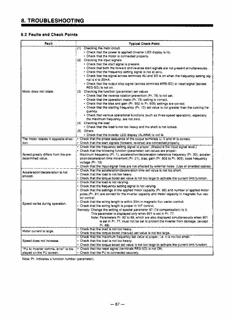
8. TROUBLESHOOTING
8.2 Faults and Check Points
Fault
vlotor does not rotate.
The motor rotates in opposite direc- .ion.
Speed greatly differs from the pre- jetermined value.
4cceleration/deceleration is not smooth.
Speed varies during operation.
Motor current is large.
Speed does not increase.
'PU to inverter comms. error" is dis- >laved on the PU screen.
Typlcal Check Polnt (1) Checking the main circuit
Checkthat the power is applied (inverter LED display is lit). Check that the motor is connected properly.
Check that the start signal is present. Check that both the forward and reverse start signals are not present simultaneously. Check that the frequency setting signal is not at zero. Check that the signal across terminals AU and SD is on when the frequency setting sig-
Check that the output stop signal (across terminals MRS-SD) or reset signal (across
(2) Checking the input signals
nal is 4 to 20mA.
RES-SD) is not on. (3) Checking the function (parameter) set values
Check that the reverse rotation prevention (Pr. 78) is not set. Check that the operation mode (Pr. 79) setting is correct. Check that the bias and gain (Pr. 902 to Pr. 905) settings are correct. Check that the starting frequency (Pr. 13) set value is not greater than the running fre-
Check that various operational functions (such as three-speed operation), especially quency.
the maximum frequency, are not zero. (4) Checking the load
(5) Others
Check that the phase sequence of the output terminals U, V and W is correct.
Check that the load is not too heavy and the shaft is not locked.
Check that the inverter LED display (ALARM) is not lit.
Check that the start signals (forward, reverse) are connected properly. 0 Check that the frequency setting signal is proper. (Measure the input signal level.)
Check that the following function (parameter) set values are proper: Maximum frequency (Pr. l), acceleration/deceleration reference frequency (Pr. 20), acceler- atioddeceleration time increment (Pr. 21), bias, gain (Pr. 902 to Pr. 905), base frequency voltage (Pr. 19) Check that the input signal lines are not affected by external noise. (Use of shielded cables) Check that the accelerationldeceleration time set value is not too short. Check that the load is not too heavy. Check that the toque boost set value is not too large to activate the current limit function. Check that the load is not varying. Check that the frequency setting signal is not varying. Check that the settings of the applied motor capacity (Pr. 80) and number of applied motor poles (Pr. 81) are correct for the inverter capacity and motor capacity in magnetic flux vec- tor control. Check that the wiring length is within 30m in magnetic flux vector control. Check that the wiring length is proper in V/F control.
Remedy: Change the setting of special parameter 97 (Td compensation) to 0. This parameter is displayed only when 801 is set in Pr. 77. Note: Parameters Pr. 82 to 99, which are also displayed simultaneously when 801
is set in Pr. 77, must not be set to protect the inverter from damage. (except Pr. 89)
Check that the load is not too heavy. Check that the toque boost (manual) set value is not too large. Check that the maximum frequency set value is proper, i.e. it is not too small. Check that the load is not too heavy. Check that the toque boost set value is not too large to activate the current limit function. Check that the reset signal (terminals RES-SD) is not ON. Check that the PU is connected securelv.
f qote: Pr. indicates a function number (parameter).
- 87 -
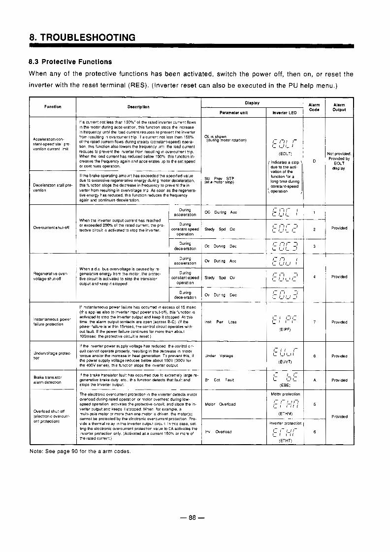
8. TROUBLESHOOTING
8.3 Protective Functions When any of the protective functions has been activated, switch the power off, then on, or reset the inverter with the reset terminal (RES). (Inverter reset can also be executed in the PU help menu.)
c I
Descrlptlon
If a current not less than 150%' of the rated Inverter current flows In the motor during acceleratlon, thls functlon stops the increase
from resulbng In overcurrent trlp If a current not less than 1 5 W In frequency unnl the load current reduces to prevent the Inverter
of the rated current Rows durlng steady (constant-speed) opera- tion, this functlon also lowers the frequency until the load current reduces to prevent the inverter from resulting In overcurrent trip When the load current has reduced below 150% this function in-
or continues operatton creases the frequency again and accelerates up to the set speed
due to excessive regeneratwe energy during motor deceleration, I f the brake operabng amount has exceeded the speclfied value
verter from resulting in overvoltage tnp As soon as the regenera- this function stops the decrease in frequency to prevent the in-
again and continues decelerabon. bve energy has reduced, this functlon reduces the frequency
During acceleration
When the inverter output current has reached or exceeded 2004b of the rated current, the pro-
WnStat-speed tective circuit is activated to stop the inverter DUrW
operation
decelerabon During
acceleration During
When a d.c bus overvoltage is caused by re- generative energy from the motor, the protec-
constant-speed tive circuit is activated to stop the Bansistor During
operation output and keep 11 stopped
decelerabon During
If instantaneeus power failure has occurred tn excess of 15 msec (this applies also to Inverter input power shut-off), this funcbon IS acbvated to stop the inverter output and keep 11 stopped At thts time, the alarm output wntacts are open (across 6-12) (If the
out fault If the power fallure continues for more than about power failure is within 15msec. the control circuit operates with-
1M)msec. the protective clrcult IS reset )
cuit cannot operate properly, resulbng In the decrease in motor If the Inverter power supply voltage has reduced, the control cir-
torque and/or the Increase In heat generatton To prevent this, If the power supply voltage reduces below about 150V (300V for the 400V series), th~s function stops the inverter output
generatwe brake duty etc , Uvs funcbon detects that fault and If the brake transistor fault has occurred due to extremely large re-
stops the inverter ourput
The electronic overcurrent protection In the Inverter detects motor overload durlng rated operation or motor overheat during low- speed operation, activates the protective clrcutt, and stops the In- verter output and keeps it stopped. When, for example, a
cannot be protected by the electontc overcurrent protecbon Pro. multi-pole motor or more than one motor IS drwen, the motor(s)
vide a thermal relay In the Inverter output clrcult In this case, set- bng the electronic overcurrent protection value to OA activates the Inverter protecbon only (Activated at a current 150% or more of the rated current )
output Alarm Display
Parameter unlt
Alarm
Inverter LED Functlon
Accelerabonicon- stant-speed stall pre- vention current llmlt
OL IS shown (during motor rotabon)
lot providec Provided by
EOLT dsplay
' Indicates a stop \ D due to the acti- vation of the function for a long tlme durlng constant-speed
~ operation. i
Stll Prev STP (at a motor stop)
Decelerabon stall pre- vention
fiercurrent shut-off
voltage shut-off Regeneratlve over-
Instantaneous power failure protection
Undervoltage protec- bon
Brake tranststor alarm detectlon
OC During Acc
Provided stedy spd o c
Ck Durlng Dec
m During Acc
stedy spd o v Provided
Dy Durlng Dec
-t-- Inst. Pwr Loss Provlded
Under Voltage Prwlded
Br. Cct. Fault Provided
Motor protectlon
Motor medoad
medoad shut-off
ent protection) (electronlc overcurr- Provided I
Inverter protectlon 1 1: f - 1-1 I- f- f I l l
Inv. medoad
Note: See page 90 for the alarm codes.
- 88 -
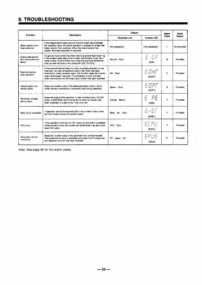
8. TROUBLESHOOTING
FumUon
heat protection Brake resistor over-
Output side grwnd fault overcurrent pro- tection
External thermal relay operation
Inboard option con- nection alarm
Parameter storage device alarm
Retry count exceeded
CPU error
Parameter unit dis- connection
Dercriptbn
It the regenerative brake amount lrwn the momr has excaeded the specified value, the brake operation is stopped to protect the brake resistor from overheat. When the brake resistor has coded, the brake operation is resumed.
(Not displayed) (Not displayed)
If a ground fault current has flown due to a ground fault occurring in the output (load) side 01 the inverter, this function stops the in- verter output. A ground fault occurring at low ground msistanca may activate the overcurrent protection (OCt to OC3).
~~~~~~ ~ ~
If the external thermal relay for motor overheat protection or the
switched on (relay contacts open), this function s t o p ttm inverter OH Fault internally mounted temperature relay in ttm motor has been
Output and keeps it stopped This protection is only provided when the external thermal relay input function has been selected
Stops the inverter output if b e dedicated option used in the in- verter results In connection (connector) fault during operation. %tion
Stops b e output if the specified number of write times (100,000 times) to EEPROM, which stores the tunction set values, hab teen exceeded or a devlce fault has occurred.
If operation cannot be resumed within the number of retry times set. this function stops the invemr output.
mined period of time, the Inverter self-determines it a6 alarm and CPU Fault If the operabon of the built-In CPU does r a t end within a predeter-
stops b e output.
Stops the inverter output if the parameter unit is disconnected This protective function is acbvated only when the PU disconnec- PU Leave a t tion detection function has been selected
Alum I Alum Cod. outpul
- Not provided
B Provided
C Provided
E Provided
F Provided
F Provided
F Provided
1 Provided
Note: See page 90 for the alarm codes.
- 89 -
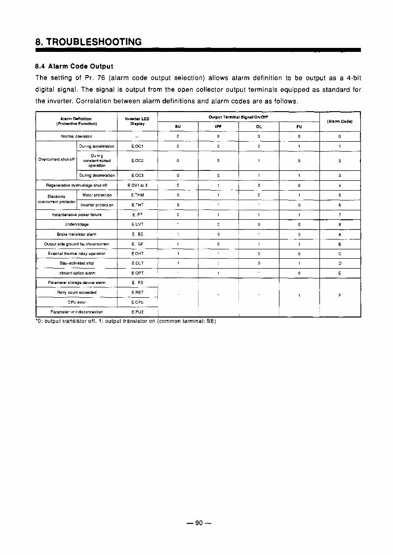
8. TROUBLESHOOTING
8.4 Alarm Code Output The setting of Pr. 76 (alarm code output selection) allows alarm definition to be output as a 4-bit digital signal. The signal is output from the open collector output terminals equipped as standard for the inverter. Correlation between alarm definitions and alarm codes are as follows.
Alarm [kflnltlon l n w r LED Output Terrnlnal Signal O n / W
su FU OL I PF (Protrtlve Functlon) Q*pl.Y (Alarm Code)
Overcurrent shutoff constant-speed During
operation E.OC2 I o l o
Regenerative overvoltage shut-off 1 E OV1 to 3 1 0 I 1 I 0 I 0 I 4
Electronic overcurrent protector
Motor protection
7 1 1 1 0 E IPF Instantanwus power failure
6 0 1 1 0 E THT Inverter protection
5 1 0 1 0 E THM -
Brake transistor alarm 1 E B E 1 1 I 0 1 1 I 0 I A
Output side ground taulVovercurrent
C 0 0 1 1 E OHT External belmal relay operation
B 1 1 0 1 E GF
Stlll-activated stop 1 E.OLT 1 1 I 1 I 0 I 1 I D
Inboard option alarm E 0 1 1 1 E.OPT
Parameter storage device alarm
Parameter unit disconnection
E CPU CPU error
E RET Retry count exceeded
E. PE
E PUE
1 F 1 1 1
0: output transistor off, 1: output transistor on (common terminal: SE)
- 90 -
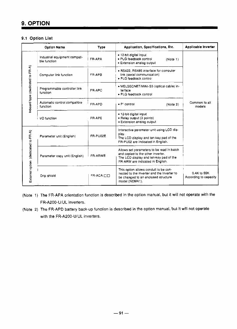
9. OPTION
9.1 Option List
t-
I
Option Name
Industrial equipment compati- ble function
Computer link function
Programmable controller link function
Automatic control compatible function
I/O function
Parameter unit (English)
Parameter copy unit (English)
Drip shield
Type
FR-APA
FR-APB
FR-APC
FR-APD
FR-APE
FR-PU02E
FR-ARWE
FR-ACA 0 0
Appllcatlon, Speclflcatlons, Etc.
12-bit digital input PLG feedback control (Note 1 ) Extension analog output
RS422, RS485 interface for computer
PLG feedback control
MELSECNET/MINI-SB (optical cable) in-
PLG feedback control
link (serial communication)
terface
PI control (Note 2)
12-bit digital input Relay output (3 points) Extension analog output
Interactive parameter unit using LCD dis- play. The LCD display and ten-key pad of the FR-PUO2 are indicated in English.
Allows set parameters to be read in batch and copied to the other inverter. The LCD display and ten-key pad of the FR-ARW are indicated in English.
Appllcable Inverter
Common to all models
This option allows conduit to be con- nected to the inverter and the inverter to
model (NEMA1). According to capacity be changed to an enclosed structure
0.4K to 55K
1
(Note 1) The FR-APA orientation function is described in the option manual, but it will not operate with the FR-A200-U/UL inverters.
(Note 2) The FR-APD battery back-up function is described in the option manual, but it will not operate
with the FR-A200-U/UL inverters.
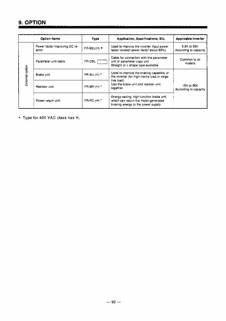
1 Optlon Name 1 Type 1 Appllcatlon, Specltlcatlons, Etc. I Appllcable Inverter
I I I
Power factor improving DC re- According to capacity factor (overall power factor about 95%). actor
5.5K to 55K Used to improve the inverter input power FR-BEL(H)
Parameter unit cable Cable for connection with the parameter
Straight or L shape type available unit or parameter copy unit Common to all
models
Brake unit FR-BU-(H) Used to improve the braking capability of the inverter (for high-inertia load or nega- tive load)
Resistor unit FR-BR-(H) Use the brake unit and resistor unit together.
15K to 55K According to capacity
Power return unit Energy-saving, high-function brake unit
braking energy to the power supply which can return the motor-generated
* Type for 400 VAC class has H.
- 92 -
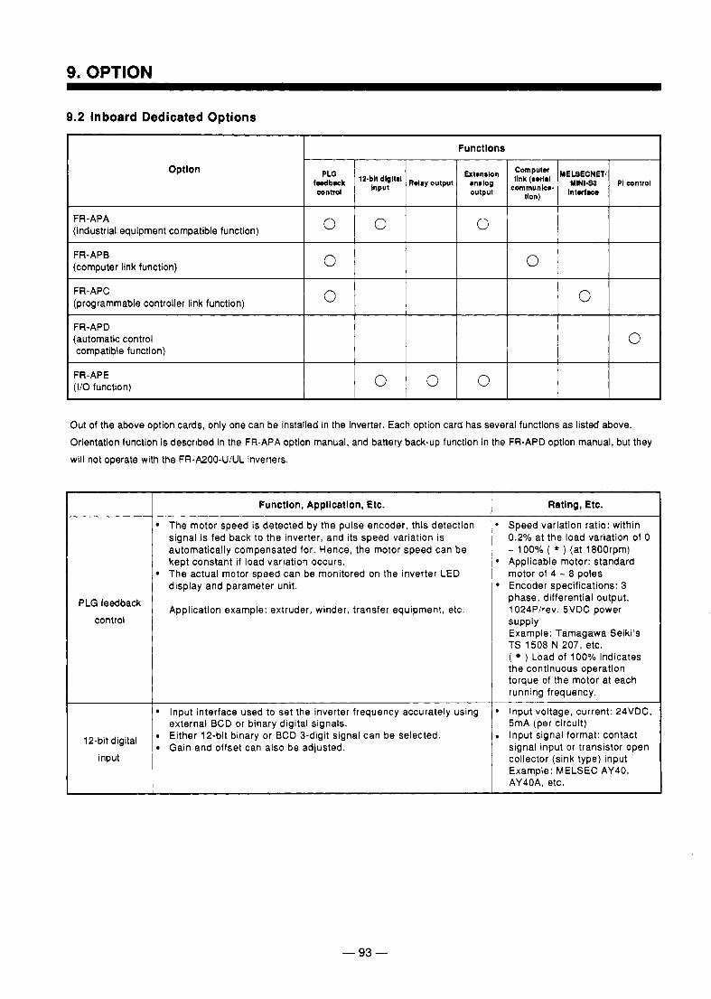
9. OPTION
9.2 Inboard Dedicated Options
I Functlons 1 Optlon
FR-APA (industrial equipment compatible function)
FR-APB (computer link function)
0 (programmable controller link function)
0 0 FR-APC 0
FR-APD (automatic control compatible function)
FR-APE (I/O function) 0 0 0
Out of the above option cards, only one can be installed in the inverter. Each option card has several functions as listed above. Orientation function is described in the FR-APA option manual, and battery back-up function in the FR-APD option manual, but they will not operate with the FR-A200-U/UL inverters.
PLG feedback control
12-bit digital input
Function, Appllcatlon, Etc.
The motor speed is detected by the pulse encoder, this detection signal is fed back to the inverter, and its speed variation is automatically compensated for. Hence, the motor speed can be kept constant if load variation occurs.
display and parameter unit.
Application example: extruder, winder, transfer equipment, etc.
The actual motor speed can be monitored on the inverter LED
Input interface used to set the inverter frequency accurately using external BCD or binary digital signals. Either 12-bit binary or BCD 3-digit signal can be selected. Gain and offset can also be adjusted.
~~~~ ~
- 93 -
Rating, Etc.
1 Speed variation ratio: within 0.2% at the load variation of 0 - 100% ( * ) (at 1800rpm)
b Applicable motor: standard motor of 4 - 8 poles
b Encoder specifications: 3 phase, differential output, 1024P/rev. 5VDC power supply Example: Tamagawa Seiki’s TS 1508 N 207, etc. ( ) Load of 100% indicates the continuous operation torque of the motor at each running frequency.
1 Input voltage, current: 24VDC, 5mA (per circuit) Input signal format: contact signal input or transistor open collector (sink type) input Example: MELSEC AY40, AY40A, etc.
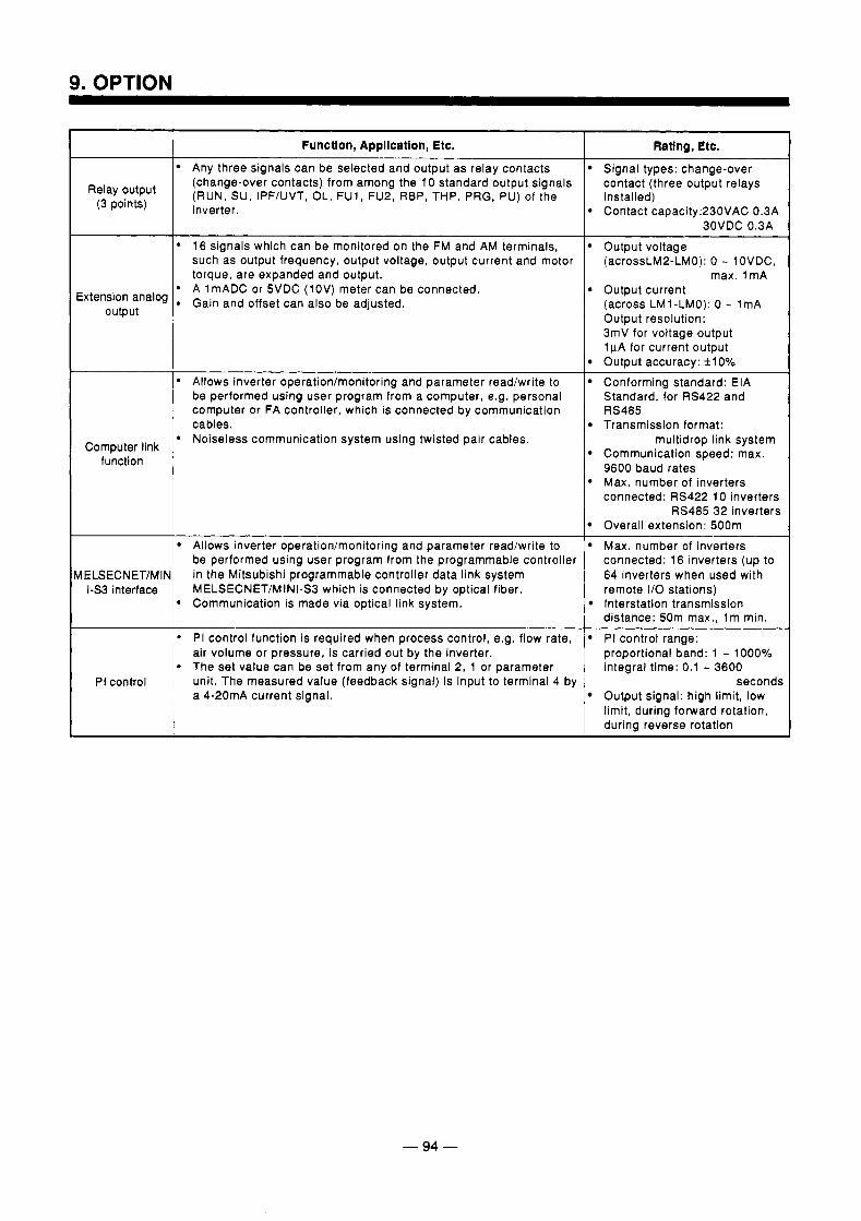
Relay output (3 points)
Extension analog output
Computer link function
hELSECNET/MlN 1-53 interface
PI control
Function, Application, Etc.
Any three signals can be selected and output as relay contacts (change-over contacts) from among the 10 standard output signals (RUN, SU, IPF/UVT, OL, FU1, FU2, REP, THP, PRG, PU) of the inverter.
, 16 signals which can be monitored on the FM and AM terminals, such as output frequency, output voltage, output current and motor torque, are expanded and output. A 1 mADC or 5VDC (1 OV) meter can be connected.
1 Gain and offset can also be adjusted.
Allows inverter operation/monitoring and parameter read/write to be performed using user program from a computer, e.g. personal computer or FA controller, which is connected by communication cables.
p Noiseless communication system using twisted pair cables.
Allows inverter operation/monitoring and parameter read/write to be performed using user program from the programmable controller in the Mitsubishi programmable controller data link system MELSECNET/MINI-S3 which is connected by optical fiber.
1 Communication is made via optical link system.
PI control function is required when process control, e.g. flow rate, air volume or pressure, is carried out by the inverter. The set value can be set from any of terminal 2, 1 or parameter unit. The measured value (feedback signal) is input to terminal 4 by a 4-20mA current signal.
Ratlng, Etc.
Signal types: change-over contact (three output relays installed) Contact capacity:230VAC 0.3A
Output voltage 30VDC 0.3A
(acrossLM2-LMO): 0 - lOVDC, max. I m A
Output current (across LM1-LMO): 0 - 1mA Output resolution: 3mV for voltage output l p A for current output Output accuracy: + lo% Conforming standard: EIA Standard, for RS422 and RS485 Transmission format:
Communication speed: max.
Max. number of inverters
multidrop link system
9600 baud rates
connected: RS422 10 inverters RS485 32 inverters
Overall extension: 500m Max. number of inverters connected: 16 inverters (up to 64 inverters when used with remote I/O stations)
distance: 50m max., l m min. lnterstation transmission
PI control range: proportional band: 1 - 1000% integral time: 0.1 - 3600
Output signal: high limit, low limit, during forward rotation, during reverse rotation
seconds
- 94 -
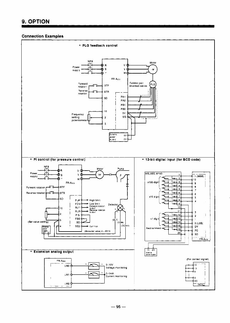
9. OPTION
Connection Examples
PLG feedback control
rotatlon STF
STR
SD
rotation
Frequency setting potentiometer
r I
I
I
shielded cables
I I I I I I I I I I I I I I
PI control (for pressure control)
Forward rotation
1 q:;. r Reverse rotation
FUP High limlt I I 1 1 - ' 1 1
I Extenslon analog output
f-*++Kh 0-1ov Voltage monitoring
O-lmA Current monltoring
I
12-bit dlgltal Input (for BCD code)
b a d mmmand
(For contact signal)
- 95 -
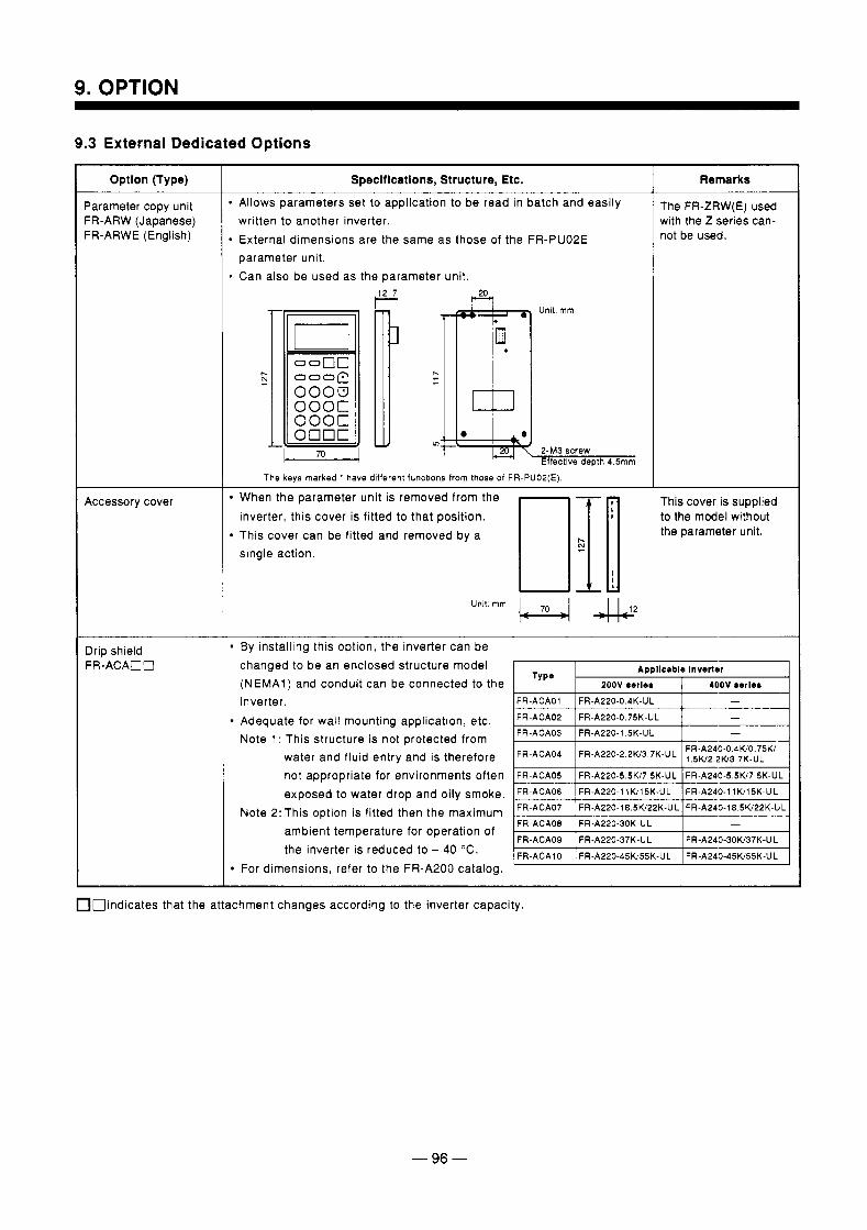
9. OPTION
9.3 External Dedicated Options
Option (Type)
Parameter copy unit FR-ARW (Japanese) FR-ARWE (English)
Accessory cover
Drip shield FR-ACAOO
Specifications, Structure, Etc.
1 Allows parameters set to application to be read in batch and easily written to another inverter.
I External dimensions are the same as those of the FR-PU02E parameter unit. Can also be used as the parameter unit.
I The keys marked * have different functions from those of FR-PUOP(E)
Remarks
The FR-ZRW(E) used with the Z series can- not be used.
When the parameter unit is removed from the inverter, this cover is fitted to that position. This cover can be fitted and removed by a single action.
Unlt: mm &
This cover is supplied to the model without the parameter unit.
By installing this option, the inverter can be changed to be an enclosed structure model (NEMA1) and conduit can be connected to the inverter. Adequate for wall mounting application, etc. Note 1 : This structure is not protected from
water and fluid entry and is therefore not appropriate for environments often exposed to water drop and oily smoke.
Note 2: This option is fitted then the maximum ambient temperature for operation of the inverter is reduced to + 40 "C.
For dimensions, refer to the FR-A200 catalog.
nindicates that the attachment changes according to the inverter capacity.
- 96 -
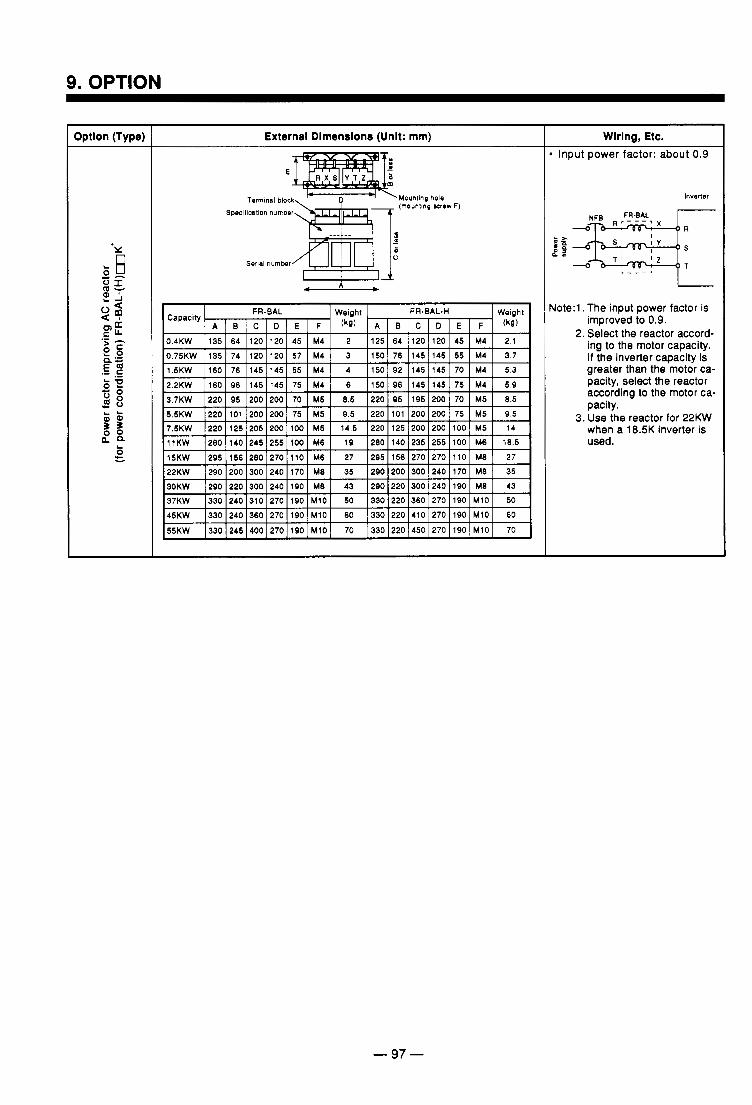
9. OPTION
Dption (Type)
Y,
External Dimensions (Unit: mm)
E
Termlnal block Spaf ical lon number
Serlal number
L A J
0.4KW
5.3 M4 70 145 145 92 150 4 M4 55 145 145 76 160 1.5KW
3.7 M4 55 145 145 76 150 3 M4 57 120 120 74 135 0.75KW
2.1 M4 45 120 120 64 125 2 M4 45 120 120 64 135
3.7KW I220 I 95 I200 I200 I 70 I M5 I 8.5 I220 I 95 I105 I200 1 70 I M5 I 8.5 5 5KW I220 I101 I200 I200 I 75 I M5 1 9.5 I220 I101 I200 I200 1 75 I M5 I 9.5 I
7.5KW
27 M8 110 270 270 156 295 27 M6 110 270 280 156 295 15KW
18.5 M6 100 255 235 140 280 19 M6 100 255 245 140 280 11KW
14 M5 100 200 200 125 220 14.5 M5 100 200 205 125 220 . . . . . . - - . . . - - .
30KW ~ 2 9 0 ~ 2 2 0 ~ 3 0 0 ~ 2 4 0 ~ 1 0 0 ~ M8 I 43 ~ 2 9 0 ~ 2 2 0 ~ 3 0 0 ~ 2 4 0 j l Q O ~ M8 I 43 37KW ~ 3 3 0 ~ 2 4 0 ~ 3 1 0 ~ 2 7 0 ~ 1 0 0 ~ M 1 0 ~ 50 ~ 3 3 0 ~ 2 2 0 ~ 3 6 0 / 2 7 0 / 1 Q O ~ M l O ~ 50
k%W- ~ 3 3 0 ~ 2 4 0 ~ 3 6 0 ~ 2 7 0 ~ 1 9 0 ~ M l O ~ 60 ~ 3 3 0 ~ 2 2 0 ~ 4 1 0 ~ 2 7 0 ~ 1 Q 0 ~ M 1 0 ~ 60 I
Wiring, Etc. Input power factor: about 0.9
lnvener
Yote:l .The input power factor is improved to 0.9.
2. Select the reactor accord- ing to the motor capacity. If the inverter capacity is greater than the motor ca- pacity, select the reactor according to the motor ca- pacity.
3. Use the reactor for 22KW when a 18.5K inverter is used.
-97-
. ... . .
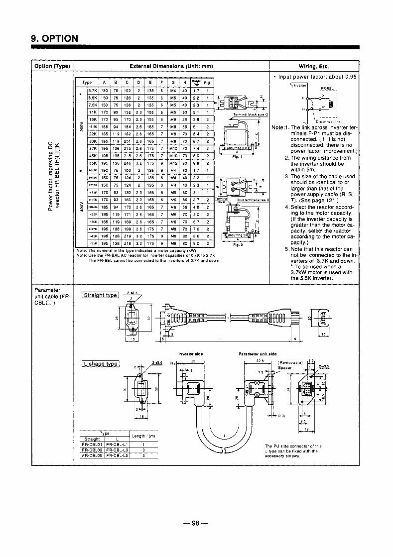
9. OPTION
External Dlmenslons (Unit: mm) I Wiring, Etc.
Type A B C D E F G H 2; Fig.
3.7K 150 75 102 2 135 6 M4 40 1.7 1 5.5K 150 75 126 2 135 6 M5 40 2.2 1 T - m =- t
> 1 8 . H 185 94 184 2.6 165 7 M8 56 5 1 2 22K 185 119 182 2.6 165 7 M8 70 5.4 2 30K 185 119 201 2.6 165 7 M8 70 6 7 2
8 -
I 3 7 K [ 1 9 5 [ 1 3 6 [ 2 1 5 / 2 . 6 1 1 7 5 1 7 I M l O I 7 0 1 7 . 4 1 2 I A
45K 195 136 215 2.6 175 7 M10 70 8.0 2 ' F I ~ . ~
55K 195 136 246 3.2 175 Q M12 80 9,8 2 H(1.71 150 75 102 2 135 6 M4 40 1.7 1
-
H 1 i K 170 93 132 2 3 155 6 M5 50 3 1 1
H I ~ K 170 93 160 2.3 155 6 M6 56 3.7 2
5 w s u 185 94 173 2.6 165 7 M6 56 4.8 2 ~ * . H22K 185 119 171 2.6 165 7 M6 70 5 0 2
1 M 5 K ] 195 I 138 1219 ] 3.2 I 175 1 9 1 M8 I 80 I 8.6 1 2 I H 5 5 K j 195 138 219 3.2 175 9 9.0 2 M8 1 80
h Fig. 2
tote: The numeral in the type indicates a motor capacity (kW). Note, Use the FR-BAL AC reactor for inverter capacities of 0 4K to 3.7K
The FR-BEL cannot be connected lo the inverters of 3 7K and down.
Input power factor: about 0.9!
J \ '----' Note:l .The link across inverter tel
Olsconnect ltnk
minals P-P1 must be dis- connected. (If it is not disconnected, there is no power factor improvement
2. The wiring distance from the inverter should be within 5m.
3. The size of the cable used should be identical to or larger than that of the power supply cable (R, S, T). (See page 121 .)
4. Select the reactor accord- ing to the motor capacity. (If the inverter capacity is greater than the motor ca- pacity, select the reactor according to the motor ca- pacity.)
not be connected to the ir verters of 3.7K and down. ' To be used when a 3.7kW motor is used with the 5.5K inverter.
5 . Note that this reactor can
I Straight type ] L>
I I I
Inverter rlde Parsnnter unlt rlde
I L shape type 1
TY pe Straiohf I L
Length I (m)
The PU side connector of this
accessory screws L type can be fixed with the
- 98 -
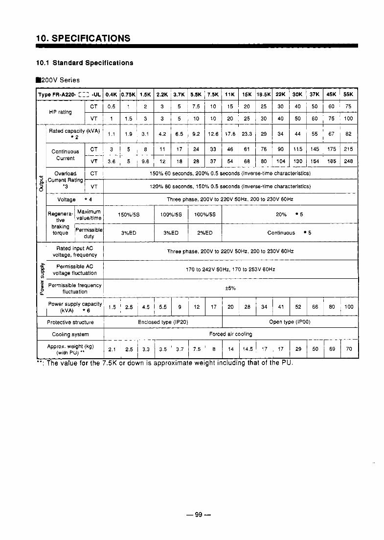
10. SPECIFICATIONS
10.1 Standard Specifications
m200V Series
rype FR-A220- I -UL I 0.4K 10.75K1 1.5K I 2.2K I 3.7K I 5.5K 1 7.5K I 11K 1 15K 118.5KI 22K I 30K 1 37K I 45K 1 55K
CT 0.5 1 2 3 5 7.5 10 15 20 25 30 40 50 60 75
VT 1 1.5 3 3 5 10 10 20 25 30 40 50 60 75 100 HP rating
I
~ Rated I 1.1 1 1.9 I 3.1 I 4.2 1 6.5 I 9.2 12.6 1 17.6 23.3 ~ 29 I 34 I 44 i 55 1 67 i 82
Continuous CT 3 5 8 11 17 24 33 46 61 76 90 11 5 145 175 21 5 Current VT 3.6 5 9.6 12 18 28 37 54 68 80 104 130 154 185 248
Overload CT 150% 60 seconds, 200% 0.5 seconds (inverse-time characteristics)
'3 VT 120% 60 seconds, 150% 0.5 seconds (inverse-time characteristics) , Current Rating
Voltage * 4 Three phase, 200V to 220V 50Hz, 200 to 230V 60Hz I I I I
Regenera- 15oyO/5s 1 Oo0/o/5s 100%/5s value/time
Permissible duty
20% 5
braking torque 3%ED 3%ED 2%ED Continuous 5
Rated input AC voltage, frequency Three phase, 200V to 220V 50Hz,200 to 230V 60Hz
Permissible AC 21
4 voltage fluctuation
$ Permissible frequency
170 to 242V 50Hz, 170 to 253V 60Hz v) I-
0 Q fluctuation
55%
Power supply capacity (kVA) * 6 1.5 2.5 4.5 5.5 9 12 17 20 28 34 41 52 66 80 100
Protective structure Enclosed type (IP20) Open type (IPOO)
Cooling system Forced air cooling
Approx'weight(kg) 2.1 2.5 3.3 3.5 3.7 7.5 8 14 14.5 17 17 29 50 69 70 (with PU) '*
+: The value for the 7.5K or down is approximate weight including that of the PU.
- 99 -
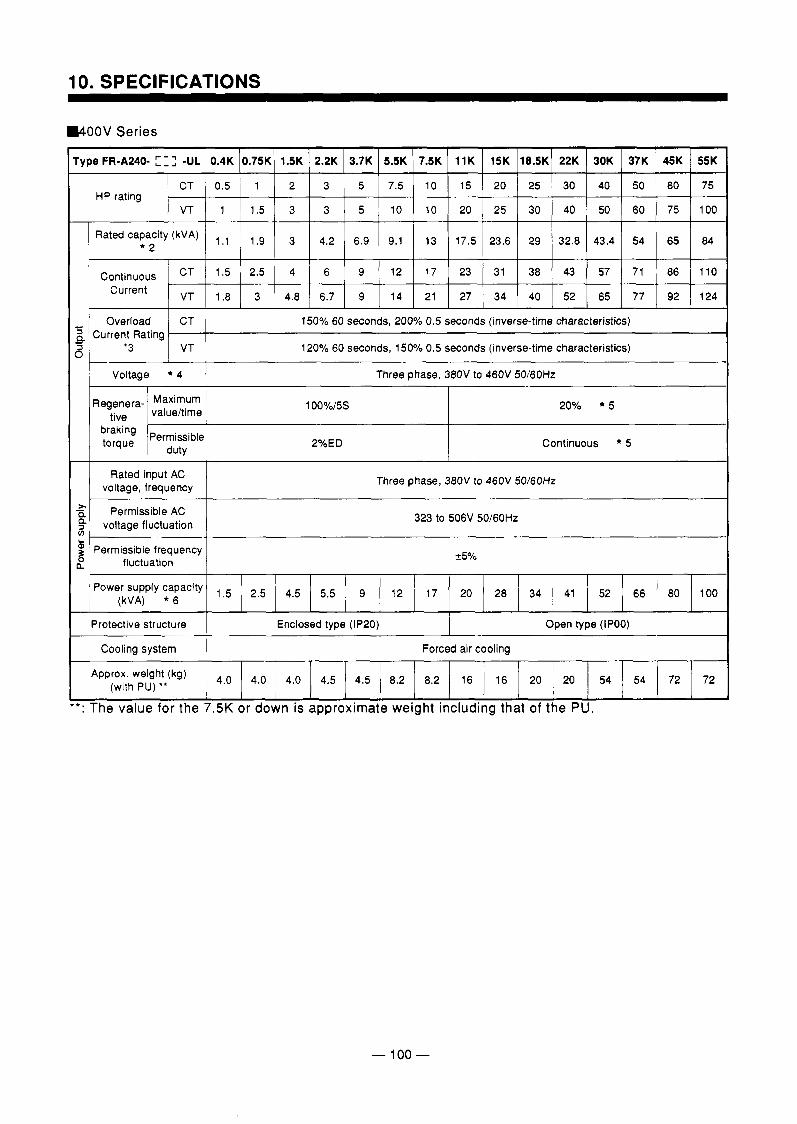
10. SPECIFICATIONS
W O O V Series
Rated capacity (kVA) 1.1 1.9 3 4.2 6.9 9.1 13 17.5 23.6 29 32.8 43.4 54 65 84 * 2
Continuous CT 1.5 2.5 4 6 9 12 17 23 31 38 43 57 71 86 110 Current VT 1.8 3 4.8 6.7 9 14 21 27 34 40 52 65 77 92 124
Overload CT 150% 60 seconds, 200% 0.5 seconds (inverse-time characteristics)
‘3 VT 120% 60 seconds, 150% 0.5 seconds (inverse-time characteristics) Current Rating
Voltage * 4 [ I Three phase, 380V to 460V 50/60Hz I I I
Rated input AC voltage, frequency Three phase, 380V to 460V 50/60Hz
Permissible AC voltage fluctuation 323 to 506V 50I60Hz
Permissible frequency fluctuation f5%
Power supply capacity (kVA) * 6 1.5 2.5 4.5 5.5 9 12 17 20 28 34 41 52 66 80 100
Protective structure I Enclosed type (IP20) I Open type (IPOO)
Forced air cooling
weight (kg) 4.0 4.0 4.0 4.5 4.5 8.2 8.2 16 16 20 20 54 54 72 72 (with PU) * *
* : The value for the 7.5K or down is approximate weight including that of the PU.
- 100 -
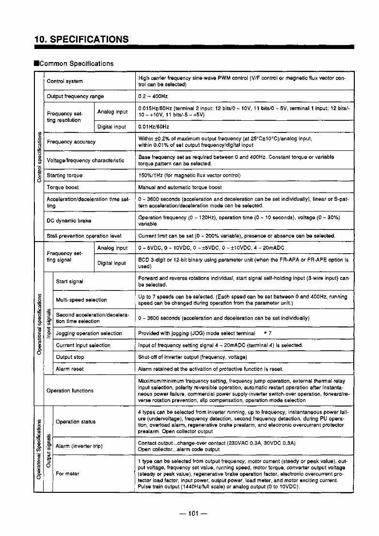
.Common Specifications
Control system
Output frequency range
ting resolution
Frequency accuracy
Voltage/frequency Characteristic
Starting torque
Torque boost
Acceleration/deceleration time set- ting
DC dynamic brake
Stall prevention operation level
Frequency set- ting signal Digital input
I
Start signal
Multi-speed selection
Second acceleration/decelera- tion time selection
Jogging operation selection
Current input selection
output stop
Alarm reset
Operation functions
Operation status
Alarm (inverter trip)
For meter
High carrier frequency sine-wave PWM control (VIF control or magnetic flux vector con- trol can be selected)
0.2 - 400HZ
0.015Hz/60Hz (terminal 2 input: 12 bits/O - lOV, 1 1 bits/O - 5V, terminal 1 input: 12 bits/- 10 - +1OV, 1 1 bits/-5 - +5V)
0.01 HiY6OHZ
Within fo.2YO of maximum output frequency (at 25"CflO0C)/analog input, within 0.01% of set output frequency/digital input
Base frequency set as required between 0 and 400Hz. Constant torque or variable torque pattern can be selected.
150%/1 Hz (for magnetic flux vector control)
Manual and automatic torque boost
0 - 3600 seconds (acceleration and deceleration can be set individually), linear or S-pat- tern acceleration/deceleration mode can be selected.
Operation frequency (0 - 120Hz), operation time (0 - 10 seconds), voltage (0 - 30%) variable
Current limit can be set (0 - 200% variable), presence or absence can be selected.
0 - SVDC, 0 - lOVDC, 0 - f5VDC, 0 - flOVDC, 4 - 20mADC
BCD 3-digit or 12-bit binary using parameter unit (when the FR-APA or FR-APE option is used)
Forward and reverse rotations individual, start signal self-holding input (3-wire input) can be selected.
Up to 7 speeds can be selected. (Each speed can be set between 0 and 400Hz, running speed can be changed during operation from the parameter unit.)
0 - 3600 seconds (acceleration and deceleration can be set individually)
Provided with jogging (JOG) mode select terminal * 7
Input of frequency setting signal 4 - 20mADC (terminal 4) is selected.
Shut-off of inverter output (frequency, voltage)
Alarm retained at the activation of protective function is reset.
Maximumlminimum frequency setting, frequency jump operation, external thermal relay input selection, polarity reversible operation, automatic restart operation after instanta- neous power failure, commercial power supply-inverter switch-over operation, forwardre- verse rotation prevention, slip compensation, operation mode selection
4 types can be selected from inverter running, up to frequency, instantaneous power fail- ure (undervoltage), frequency detection, second frequency detection, during PU opera- tion, overload alarm, regenerative brake prealarm, and electronic overcurrent protector prealarm. Open collector output
Contact output ... change-over contact (230VAC 0.3A, 3OVDC 0.3A) Open collector ... alarm code output
1 type can be selected from output frequency, motor current (steady or peak value), out- put voltage, frequency set value, running speed, motor torque, converter output voltage (steady or peak value), regenerative brake operation factor, electronic overcunent pro- tector load factor, input power, output power, load meter, and motor exciting current. Pulse train output (1440HiYfull scale) or analog output (0 to 10VDC).
- 101 -
. . . . .- . .
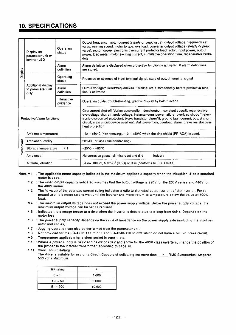
I O . SPECIFICATIONS
Display on '
parameter unit or inverter LED
Output frequency, motor current (steady or peak value), output voltage, frequency set value, running speed, motor torque, overload, converter output voltage (steady or peak
Operating status value), motor torque, electronic overcurrent protector load factor, input power, output
power, load meter, motor exciting current, cumulative operation time, regenerative brake duty
Alarm
status Presence or absence of input terminal signal, state of output terminal signal Operating
are stored. definition Alarm definition is displayed when protective function is activated. 8 alarm definitions
Additional display to parameter unit definition only
Alarm Output voltage/current/frequency/l/O terminal state immediately before protective func- tion is activated
guidance Interactive Operation guide, troubleshooting, graphic display by help function
Protective/alarm functions
Overcurrent shut-off (during acceleration, deceleration, constant speed), regenerative overvoltage shut-off, undervoltage, instantaneous power failure, overload shut-off (elec- tronic overcurrent protector), brake transistor alarm'8, ground fault current, output short circuit, main circuit device overheat, stall prevention, overload alarm, brake resistor over-
I I heat protection
Ambient temperature
90%RH or less (non-condensing) Ambient humidity
-10 - +50°C (non-freezing), -10 - +40°C when the drip shield (FR-ACA) is used.
Below 1000m, 5.9m/S2 (0.6G) or less (conforms to JIS C 091 1) Altitude, vibration
No corrosive gases, oil mist, dust and dirt indoors Ambience
-20°C - 4 5 ° C Storage temperature * 9
Note: 1 : The applicable motor capacity indicated is the maximum applicable capacity when the Mitsubishi 4-pole standard motor is used.
* 2 : The rated output capacity indicated assumes that the output voltage is 220V for the 200V series and 440V for the 400V series.
* 3 : The YO value of the overload current rating indicates a ratio to the rated output current of the inverter. For re- peated use, it is necessary to wait until the inverter and motor return to temperature below the value at 100% load.
4 : The maximum output voltage does not exceed the power supply voltage. Below the power supply voltage, the maximum output voltage can be set as required.
* 5 : Indicates the average torque at a time when the inverter is decelerated to a stop from 60Hz. Depends on the motor loss.
* 6 : The power supply capacity depends on the value of impedance on the power supply side (including the input re. actor and cables).
* 7 : Jogging operation can also be performed from the parameter unit. * 8 : Not provided for the FR-A220-11 K to 55K and FR-A240-11 K to 55K which do not have a built-in brake circuit.
9 : Temperature applicable for a short period in transit, etc. * 10 : Where a power supply is 342V and below or 484V and above for the 400V class inverters, change the position of
* 11 : Short Circuit Ratings the jumper to the internal transformer, according to page 13.
The drive is suitable for use on a Circuit Capable of delivering not more than RMS Symmetrical Amperes, 500 volts Maximum.
HP rating * 0 - 1 1.000
1.5 - 50
10.000 51 - 200 5.000
A
- 102 -
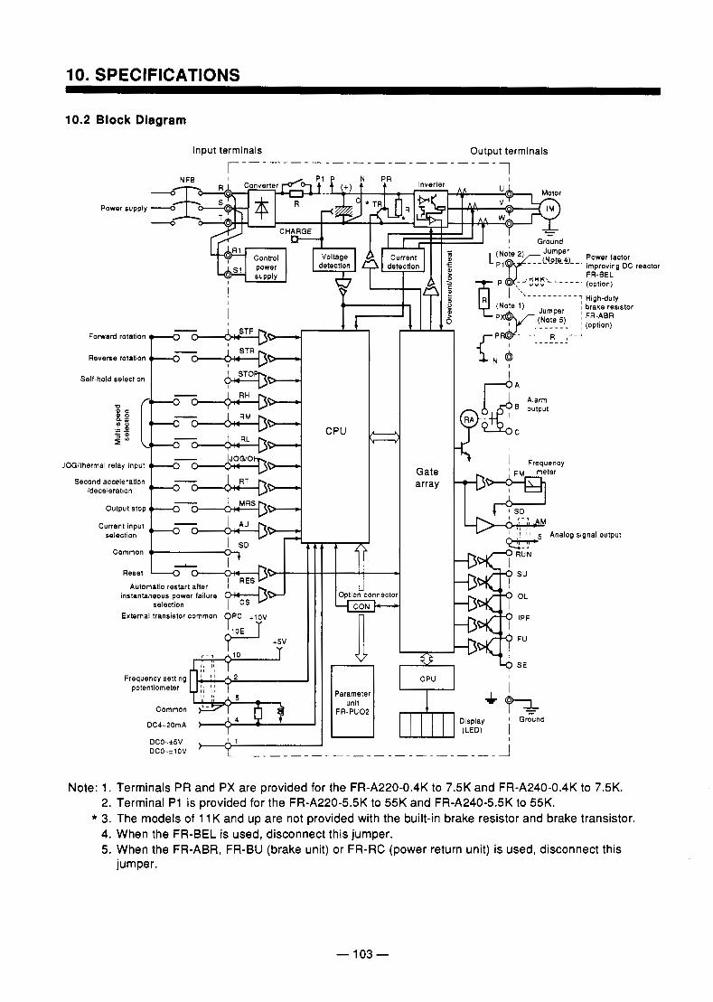
10. SPECIFICATIONS
10.2 Block Diagram
Power supply
I
I 1 I
CPU
Gate
,
Second acceleration /deceleration
output stop
Current input selection
Common
Reset Automatic restart after
instantaneous power failure selection
External transistor common ?PC + l 2 V
@-J +5v r Frequency setting
potentiometer I 1 I 1
Common '- DC4-20mA
4 option connector
array
I - - - - - - - L $
n ?E Parameter
FR-PUOP unit
Power lactor improving DC FR-BEL (option)
High-duty brake resistor FR-ABR (option)
Analog signal OUtDUt
reactor
Note: 1. Terminals PR and PX are provided for the FR-A220-0.4K to 7.5K and FR-A240-0.4K to 7.5K. 2. Terminal P1 is provided for the FR-A220-5.5K to 55K and FR-A240-5.5K to 55K.
* 3. The models of 11 K and up are not provided with the built-in brake resistor and brake transistor. 4. When the FR-BEL is used, disconnect this jumper. 5. When the FR-ABR, FR-BU (brake unit) or FR-RC (power return unit) is used, disconnect this
jumper.
-- -. . . .
- 103 -
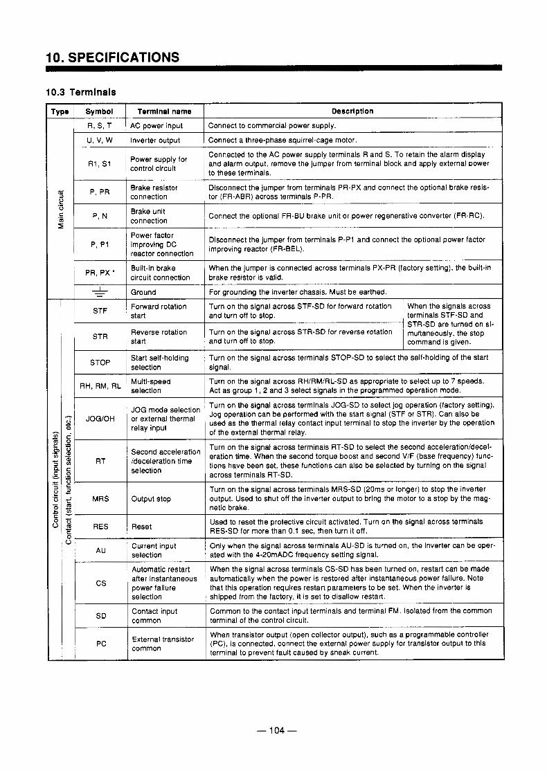
Power factor improving DC reactor connection
Disconnect the jumper from terminals P-P1 and connect the optional power factor improving reactor (FR-BEL).
~ PR,PX' I Built-in brake When the jumper is connected across terminals PX-PR (factory setting), the built-in circuit connection brake resistor is valid.
-L
When the signals across Turn on the signal across STF-SD for forward rotation Forward rotation STF
Ground ~~ ~
- - For grounding the inverter chassis. Must be earthed.
start
multaneously, the stop Turn on the signal across STR-SD for reverse rotation Reverse rotation STR
terminals STF-SD and and turn off to stop. STR-SD are turned on si-
start
Turn on the signal across terminals STOP-SD to select the self-holding of the start Start self-holding selection
command is given. and turn off to stop.
signal.
10.3 Terminals
Type Descrlptlon Termlnal name Symbol
Connect a three-phase squirrel-cage motor. Inverter output U, V, W
Connect to commercial power supply. AC power input R, S, T
Connected to the AC power supply terminals R and S. To retain the alarm display
to these terminals. R1 I " control circuit
Power supply for and alarm output, remove the jumper from terminal block and apply external power
.- 4-
connection '1 m Brake unit .- c
Disconnect the jumper from terminals PR-PX and connect the optional brake resis- Brake resistor p, PR a tor (FR-ABR) across terminals P-PR. connection .- e 0
Connect the optional FR-BU brake unit or power regenerative converter (FR-RC). r
-
- v) 2 0 v) .- c a n .- - c .- - a F
2 .- 0 - 4- C s
-
1 RH, RM, RL 1 Multi-speed Turn on the signal across RH/RM/RL-SD as appropriate to select up to 7 speeds. selection Act as group 1, 2 and 3 select signals in the programmed operation mode.
~~~ ~
Turn on the signal across terminals JOG-SD to select jog operation (factory setting).
- 0 used as the thermal relay contact input terminal to stop the inverter by the operation Or thermal mode selection Jog operation can be performed with the start signal (STF or STR). Can also be
a, relay input of the external thermal relay.
Turn on the signal across terminals RT-SD to select the second acceleration/decel- eration time. When the second torque boost and second V/F (base frequency) func-
.- s 3
selection .- 0
Second acceleration
?i
across terminals RT-SD.
- a c v) RT 'deceleration time tions have been set, these functions can also be selected by turning on the signal - 0 c c a Turn on the signal across terminals MRS-SD (20ms or longer) to stop the inverter
MRS output. Used to shut off the inverter output to bring the motor to a stop by the mag- Output stop 4- v)
0
netic brake.
Used to reset the protective circuit activated. Turn on the signal across terminals - c
I m RES-SD for more than 0.1 sec, then turn it off. c Reset RES
5 Current input ated with the 4-20mADC frequency setting signal. selection Only when the signal across terminals AU-SD is turned on, the inverter can be oper-
Common to the contact input terminals and terminal FM. Isolated from the common Contact input
shipped from the factory, it is set to disallow restart. selection
automatically when the power is restored after instantaneous power failure. Note after instantaneous When the signal across terminals CS-SD has been turned on, restart can be made Automatic restart
cs that this operation requires restart parameters to be set. When the inverter is power failure
SD terminal of the control circuit. common
External transistor common
When transistor output (open collector output), such as a programmable controller (PC), is connected, connect the external power supply for transistor output to this terminal to prevent fault caused by sneak current.
- 104 -
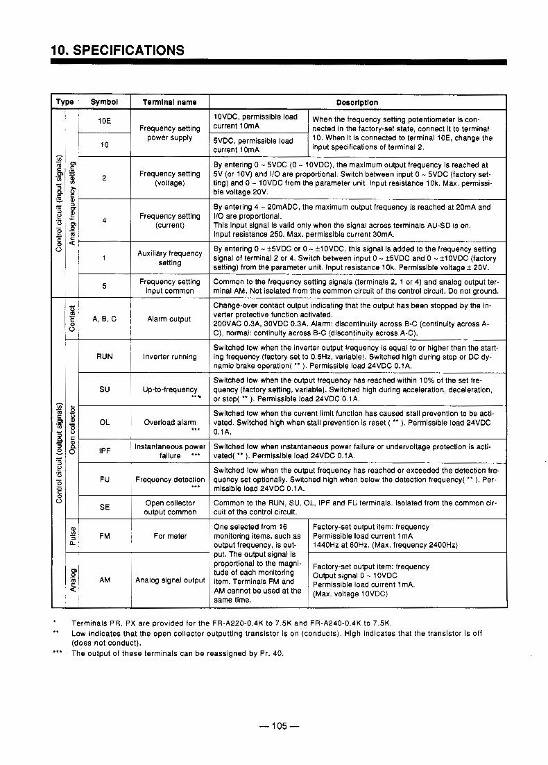
!
? :
I
' I
t
.I-
0 8 E A, B, C
RUN
I I
3 i,,, I FU
-L $ 1 FM L
Termlnal name
Frequency setting power supply
Frequency setting (voltage)
Frequency setting (current)
Auxiliary frequency setting
Frequency setting input common
Alarm output
Inverter running
Up-to-frequency tt
Overload alarm *,. Instantaneous power
failure '**
Frequency detection .tt
Open collector output common
For meter
Analog signal output
Descrlptlon
loVDC~ permissible load
current 1 OmA 10. When it is connected to terminal 1 OE, change the BVDC, permissible load nected in the factory-set state, connect it to terminal current 1 OmA When the frequency setting potentiometer is con-
By entering 0 - 5VDC (0 - lOVDC), the maximum output frequency is reached at 5V (or 1OV) and I/O are proportional. Switch between input 0 - 5VDC (factory set- ting) and 0 - 1 OVDC from the parameter unit. Input resistance 1 Ok. Max. permissi- ble voltage 20V.
By entering 4 - 20mADC, the maximum output frequency is reached at 20mA and 110 are proportional. This input signal is valid only when the signal across terminals AU-SD is on. Input resistance 250. Max. permissible current 30mA.
input specifications of terminal 2.
By entering 0 - f5VDC or 0 - +lOVDC, this signal is added to the frequency setting Signal of terminal 2 or 4. Switch between input 0 - +5VDC and 0 - k1OVDC (factory setting) from the parameter unit. Input resistance 10k. Permissible voltage f 2OV.
Common to the frequency setting signals (terminals 2, 1 or 4) and analog output ter- minal AM. Not isolated from the common circuit of the control circuit. Do not ground.
~ ~ ~_____
Change-over contact output indicating that the output has been stopped by the in- verter protective function activated. 2OOVAC 0.3A, 30VDC 0.3A. Alarm: discontinuity across B-C (continuity across A- C), normal: continuitv across B-C (discontinuitv across A-C).
Switched low when the inverter output frequency is equal to or higher than the start- ing frequency (factory set to 0.5Hz, variable). Switched high during stop or DC dy- namic brake operation( ** ). Permissible load 24VDC 0.1A.
Switched low when the output frequency has reached within 10% of the set fre- quency (factory setting, variable). Switched high during acceleration, deceleration, or stop( ** ). Permissible load 24VDC 0.1A. 1 Switched low when the current limit function has caused stall prevention to be acti- vated. Switched high when stall prevention is reset ( ** ). Permissible load 24VDC 0.1A.
Switched low when instantaneous power failure or undervoltage protection is acti- vated( * * ). Permissible load 24VDC 0.1A.
Switched low when the output frequency has reached or exceeded the detection fre- quency set optionally. Switched high when below the detection frequency( ** ). Per- missible load 24VDC 0.1A.
Common to the RUN, SU, OL, IPF and FU terminals. Isolated from the common cir- cuit of the control circuit.
~~
One selected from 16
put. The output signal is 1440Hz at 60Hz. (Max. frequency 2400Hz) output frequency, is out- Permissible load current 1mA monitoring items, such as Factory-set output item: frequency
proportiona'.to the "lagni-
same time. (Max. voltage 1 OVDC) AM be used at the Permissible load current 1 mA. Terminals FM and Output signal - OVDC tude of each monitoring Factory-set output item: frequency
Terminals PR, PX are provided for the FR-A220-0.4K to 7.5K and FR-A240-0.4K to 7.5K. Low indicates that the open collector outputting transistor is on (conducts). High indicates that the transistor is off (does not conduct).
.tt The output of these terminals can be reassigned by Pr. 40.
- 105 -
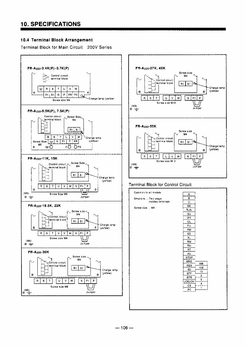
10. SPECIFICATIONS
10.4 Terminal Block Arrangement Terminal Block for Main Circuit 200V Series
FR-Az~o-O.~K(P) -~ .~K(P) El terminal ; n ; d block
@ B R1 S1 N P PR P X
Screw size M4 Charge lamp (yellow)
FR-A220-5.5K(P), 7.5K(P)
FR-A220-11 K, 15K
[ B r , m i n a l block [, RIM;sl ,q Control circuit Screw Size
Charge lamp (yellow)
0 R S T U V W N P l P
Screw Size M6 Jumper
FR-A220-18.5K, 22K
Control circuit terminal block
I I
(Me) @ + Jumper
Charge lamp (yellow)
Charge lamp (yellow)
Screw slze Me
> - Jumper ( M y
F R - A z z o - ~ ~ K , 45K
Charge lamp (yellow)
(Me1 Screw size M10 > * Jumper
F R - A z z o - ~ ~ K
Control circuit
(yellow) Charge lamp
Screw size M12
Jumper
Terminal Block for Control Circuit Common to all models
Structure. . Two-stage molded terminals
Screw size . M3 SE
RM
RT
STF ST R
JOGiOH
PC
- 106 -
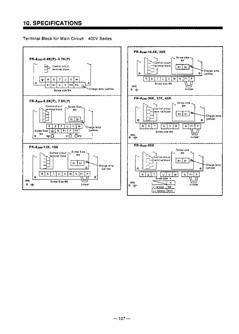
10. SPECIFICATIONS
Terminal Block for Main Circuit 400V Series
Control circuit terminal block 1
-barge R1 S1 Screw N size P M4 PR PX lamp (yellow)
FR-A240-5.5K(P), 7.5K(P)
L
Charge lamp
M4
FR-AMo-~ 1 K, 15K
- 107 -
FR-A240-18.5K, 22K
R S T U V W N P l P
\u/ Jumper
Charge lamp (yellow)
F R - A ~ ~ o - ~ O K , 37K, 45K
Control circuit termlnal block
Charge lamp (yellow)
w/ Jumper
Screw size
Screw size *
UL version M10
LY Jumper
-Charge lamp (yellow)
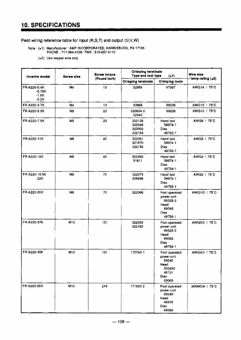
IO. SPECIFICATIONS
Field wiring reference table for input (R,S,T) and output (U,V,W) Note (*1) Manufacturer : AMP INCORPORATED, HARRISBURG, PA 17105
PHONE : 717-564-0100 TWX 510-657-4110 (+2) Use copper wire only
Screw torque 1 Type and tool,type (el) Crimping terminals
(Pound inch) Crimping terminals Crimping tools
Wire size I temp-rating ( 4 Invertre model Screw size
FR-A220-0.4K -0.75K -1.5K -2.2K
13 47387 AWG14 I 75'C 32959
M4 AWGlO I 75'C 59239 320634-0 23 M5 AWG10 I 75'C 59239 32968 13
32543
M5 23 Hand tool
Dies 59974-1
48752-1
AWG8 I 75'C 3221 28 322048 322002 322 154
FR-A220-11 K M6 40 Hand tool
Dies 59974- 1
48753-1
AWG6 I 75'C 322051 321 670 3221 55
~ ~ ~~ ~ ~~ ~ ~
M6 40 ~~~
322053 59974-1 3181 1
Hand tool
Dies 48754-1
M8 Hand tool 322074 70 326896 59974- 1
Dies 48755-1
M8 Foot operated 322086 70 power unit
Head
Dies
69325-3
69066
48756-1
FR-A220-18.5K -22K
AWG2 I 75'C
AWG110 I 75'C
M10 AWG3lO I 75'C Foot operated 322059 131 322 160 power unit
69325-3 Head
Dies 69066
48758-1 M I 0 AWG410 I 75'C Foot operated 170740-1 131
power unit 69040
Head 300430 48131
69065 Dies
M I 2 3OOMCM I 75'C Foot operated 171500-2 219 power unit
69040 Head
4881 6 Dies
69060
- 108 -
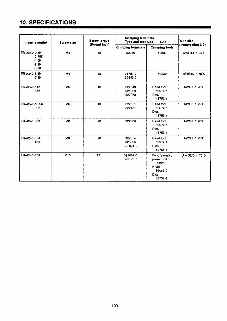
I I
FR-A240-0.4K -0.75K -1.5K -2.2K -3.7K
M4 13 I 32959 47387 AWG14 I 75'C
FR-A240-5.5K -7.5K
M4 13 35787-0 32543-0
AWGlO I 75'C 59239
FR-A240-11 K AWGB I 75'C Hand tool 322049 40 M6 -15K 59974-1 321669
327268 Dies 48752- 1
FR-A240-18.5K AWGG I 75'C Hand tool 322051 40 M6 -22K 59974-1 3221 51
Dies 48753-1
FR-A240-30K AWGG I 75'C Hand tool 322006 70 M8 59974- 1
48753- 1 Dies
FR-A240-37K -45K
M8 70 322074 326896
322074-0
Hand tool
Dies 59974-1
48755-1
AWG2 I 75'C
FR-A240-55K AWG210 I 75'C Foot operated 322087-0 131 M10 3221 73-0 power unit
69325-3 Head
Dies 69066-0
48757- 1
- 109 -
. ..
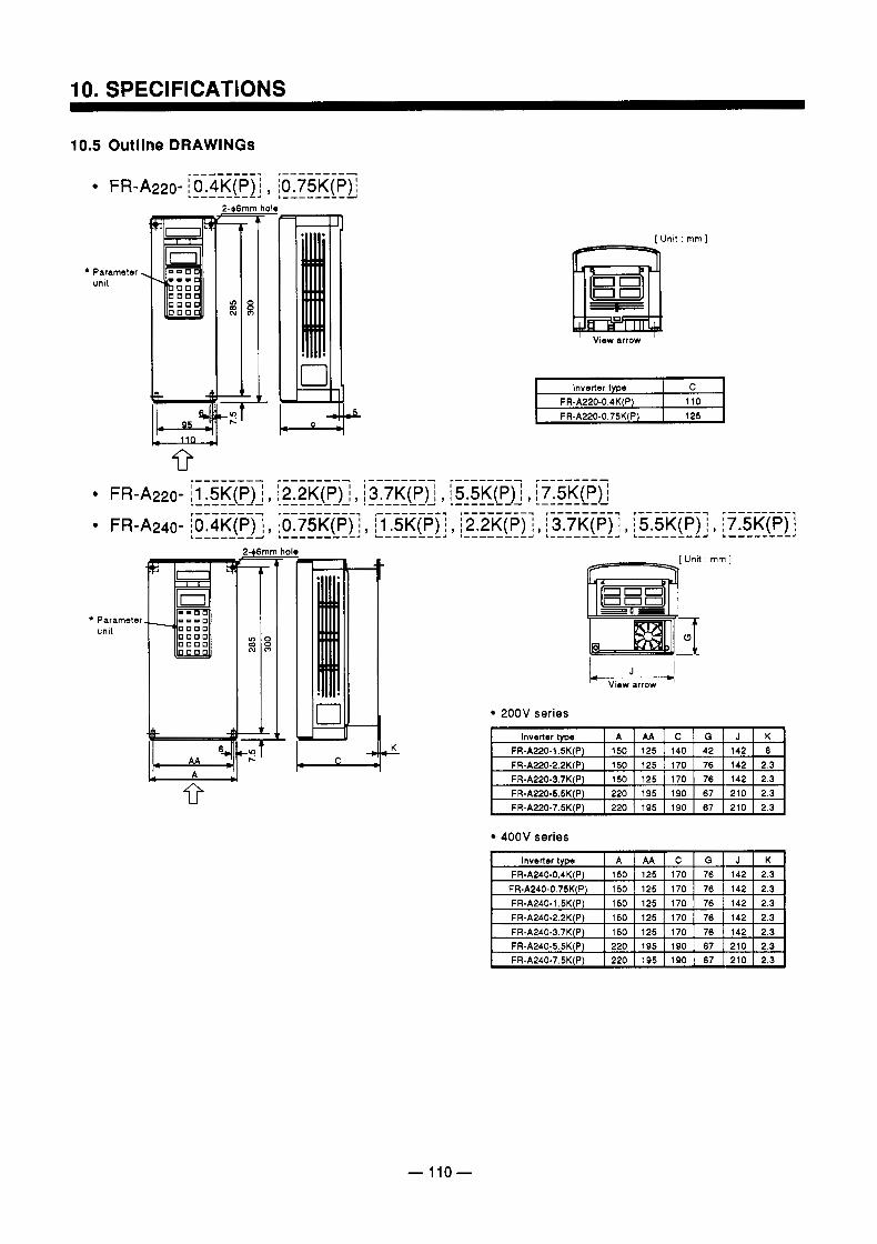
IO. SPECIFICATIONS
10.5 Outllne DRAWINGS
+ Parameter unit
-4 I C
9
[ Unit : mm ]
0
' View arrow '
inverter type C FR-A220-0.4K(P) 110 FR-A220-0.75K(P) 125
+ Parameter unit
w View arrow
200V series
,K
400V series
- 110-
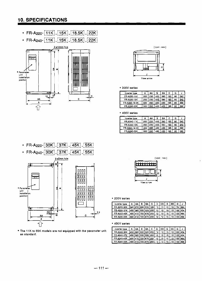
10. SPECIFICATIONS
Parameter unit I positio installation
1
* Parameter unit m I installation position T W W
1
I
!-$Dmm hole
[Unit : mm]
L J 4 View arrow
200V series
400V series
[Unit : mm]
J View arrow
200V series
+ 3.2
U
* The 11 K to 55K models are not equipped with the parameter unit as standard.
400V series
Inverter type J 0 EE E DD D C EA B AA A FR-A240-30K
434 130 10 15 12 12 250 525 550 380 450 FRoA240-37K 434 130 10 15 12 12 250 525 550 380 450
FR-A240-45K 14801410(70016751250I 12 I 1 2 I 1 5 I 1 0 (1301464 FR-A240-55K )480)410)7001675)250 I 12 1 1 2 I 1 5 110 ) I301464
- 111 -
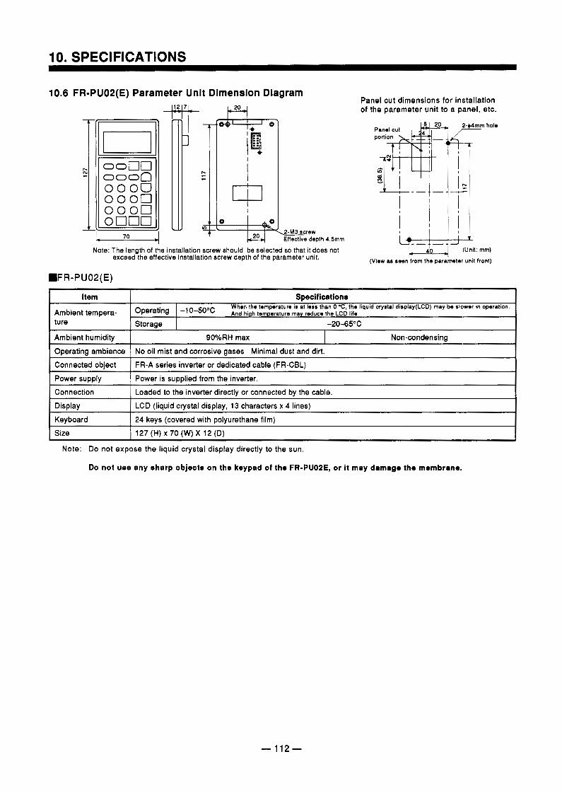
10.6 FR-PUOS(E) Parameter Unit Dimension Diagram
I 1 1 / 1 1 1 1 W . l i t- I
r-, c
Effective depth 4.5mm
Panel cut dimensions for installation of the parameter unit to a panel, etc.
I ' I
+k (View as seen from the par 'an
Frn hole
(Unit: mm)
mter unit front)
Item Specifications Ambient tempera- ture
-10-50"c And high temperature may reduce the LCD life. Operating Storage -2045°C
Ambient humidity
127 (H) x 70 (W) X 12 (D) Size 24 keys (covered with polyurethane film) Keyboard
LCD (liquid crystal display, 13 characters x 4 lines) Display
Loaded to the inverter directly or connected by the cable. Connection
Power is supplied from the inverter. Power supply
FR-A series inverter or dedicated cable (FR-CBL) Connected object
No oil mist and corrosive gases Minimal dust and dirt. Operating ambience Non-condensing 90%RH max
When the temperature is at less than 0 'C, the liquid crystal diaplay(LCD) may be slower in operation.
Note: Do not expose the liquid crystal display directly to the sun.
Do not use any sharp objects on the keypad of the FR-PUOPE, or it may damage the membrane.
-112-
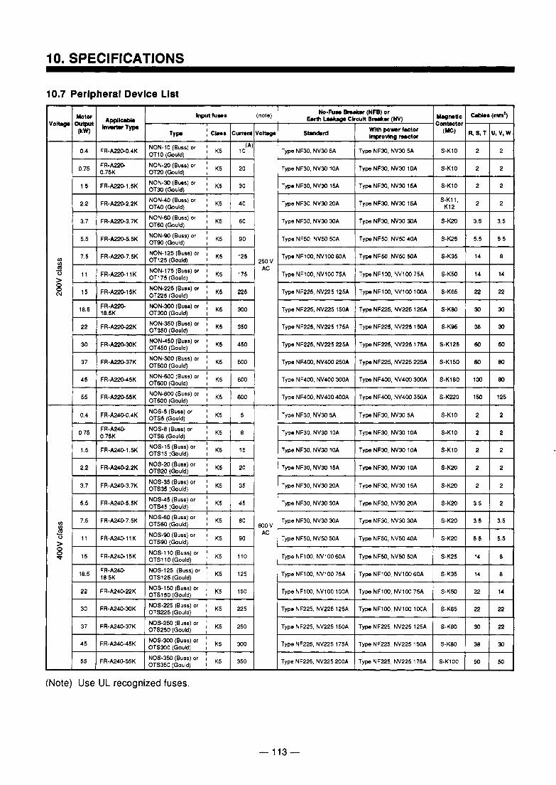
10. SPECIFICATIONS
10.7 Peripheral Device List
0.4 [ FR-ASU0.4K I NoN-lo(Buss)or I K5 I 10 (A)
OT10 (Gould) I
250 V AC
600 v AC
22 FR.A2G22K NOS-150 (Buss) or OTS150(Gould) 1 K5 NOS-225 (Buss) or I
OTS225(Gould) ! K5
150
3o FR-Ma30K 225
37 FR-A24&37K I K5 250 I
NOS-300 (BUSS) or K5 45
FR.A2GsK 55
OTS300(Gould) I
NOS-350 (BUSS) or I
300 I
OTS350 LGouldI 1 K5 350
Type NF225, NV225 150A
50 50 S-K100 Type NF225, NV225 175A Type NF225, NV225 200A
30 38 S-KW Type NF225, NV225 lSOA Type NF225, N V Z 5 175A
22 30 S-KW Type NF225, NV225 125A
(Note) Use UL recognized fuses.
- 113 -
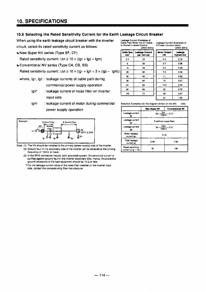
10. SPECIFICATIONS
10.8 Selecting the Rated Sensitivity Current for the Earth Leakage Circult Breaker When using the earth leakage circuit breaker with the inverter Leakage Cunent Ex-1- of
circuit, select its rated sensitivity current as follows: New Super NV series (Type SF, CF)
Cable Path When the CV Cable Leakage Current Examples of Is Routed in Metal Conduit 3-Phase Induction Motor
(xK)V 60Hz) (2odV 6OHz)
Rated sensitivity current: IAn 2 10 x (lgi + Ig2 + Igm) Conventional NV series (Type CA, CS, SS) 0.26
where, Igi, 192 : leakage currents of cable path during commercial power supply operation
Ign' : leakage current of noise filter on inverter input side
Igm : leakage current of motor during commercial
. . .
Rated sensitivity current: IAn 2 10 x {lgi + Ign + 3 x (lg2 + Igm)} 1- '-1 18.5 0.65
60 0.72 la, 70 30 0.87
37 1 .w
power supply operation
I I Note: (1) The NV should be installed to the primary (power supply) side of the inverter.
(2) Ground fault in the secondary side of the inverter can be detected at the running
(3) In the W E connection nemal point grounded system, the sensitivity current is frequency of 120Hz or lower.
purified against ground fault in the inverter secondary side. Hence, the protective ground resistance of the load equipment should be 10 s2 OT less . side, contact the corresponding filter manufacturer. For the leakage current value of the noise filter installed on the inverter input
Selection Examples (for the diagram shown on the left) (mA)
33~-=0.17
Leakage current
Leskage current b2
3 3 x m z 2 . 3 1 1000m
I I Mdor m e
current lgm
Total leakage current Ig
current le x 10) Rated sensitivity 30 la,
- 114-
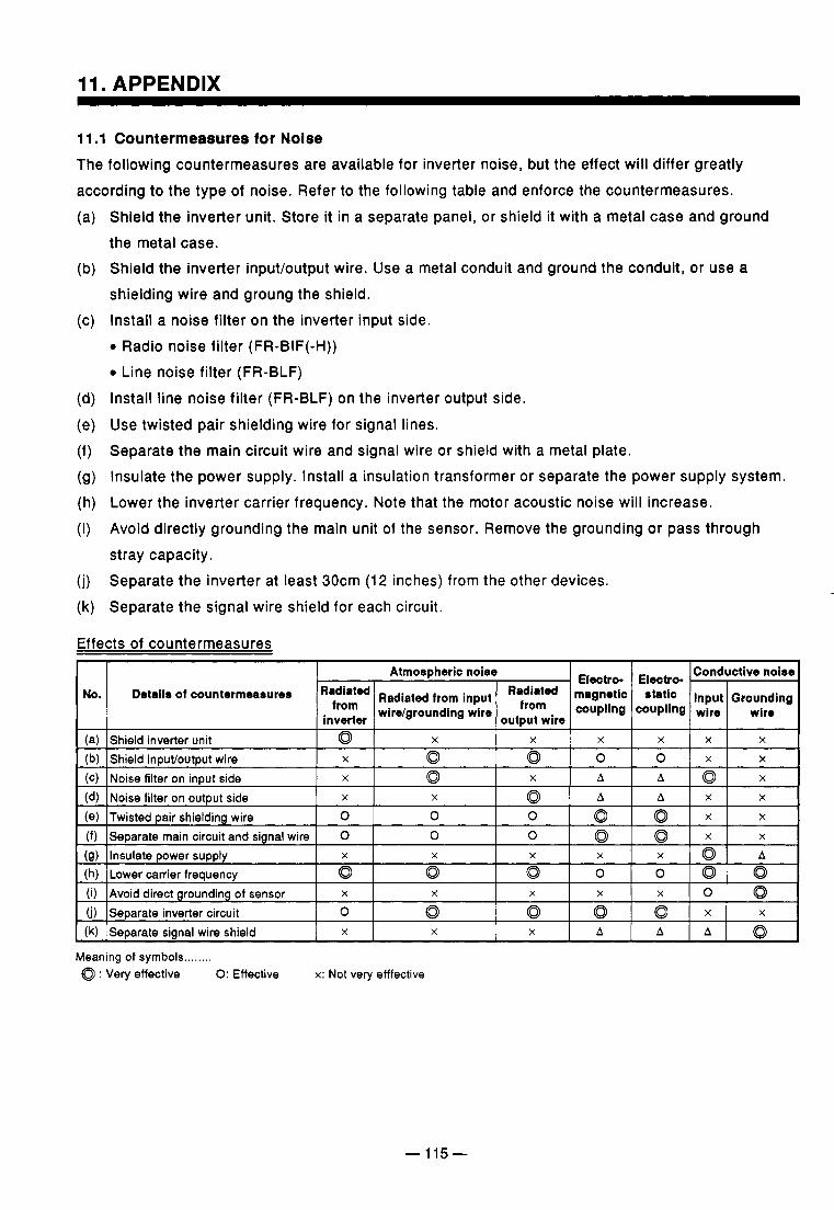
11. APPENDIX ~ ~ ~ ~~ ~ ~ ~~~~ ~~
11.1 Countermeasures for Noise The following countermeasures are available for inverter noise, but the effect will differ greatly according to the type of noise. Refer to the following table and enforce the countermeasures.
Shield the inverter unit. Store it in a separate panel, or shield it with a metal case and ground the metal case. Shield the inverter input/output wire. Use a metal conduit and ground the conduit, or use a shielding wire and groung the shield. Install a noise filter on the inverter input side. 0 Radio noise filter (FR-BIF(-H)) 0 Line noise filter (FR-BLF) Install line noise filter (FR-BLF) on the inverter output side.
Use twisted pair shielding wire for signal lines. Separate the main circuit wire and signal wire or shield with a metal plate. Insulate the power supply. Install a insulation transformer or separate the power supply system. Lower the inverter carrier frequency. Note that the motor acoustic noise will increase. Avoid directly grounding the main unit of the sensor. Remove the grounding or pass through stray capacity. Separate the inverter at least 30cm (12 inches) from the other devices. Separate the signal wire shield for each circuit.
Effects of countermeasures
Atmospheric noise Electro- Electro- Conductive noise
NO. Grounding Input static magnetic Radiated Radiated from input Radiated Details of countermeasures
inverter from wirdgrounding wire wire Wire coupling coupling from
output wire (a)
X A 0 A X 0 X Noise filter on inout side (C)
X X 0 0 Q Q X Shield input/output wire (b) X X X X X X 0 Shield inverter unit
Meaning of symbols ........ 0 : Very effective 0: Effective x: Not very efffective
-115-
......
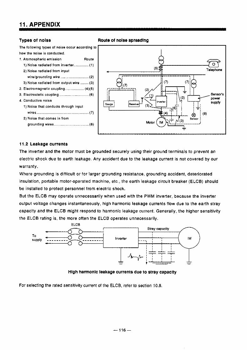
Types of noise Route of nolse spreading The following types of noise occur according to how the noise is conducted. 1 . Atomospheric emission Route
1 ) Noise radiated from inverter ................ (1 ) 2) Noise radiated from input
wire/grounding wire .............................. (2) 3) Noise radiated from output wire ......... (3)
2. Electromagnetic coupling .................... (4)(5) 3. Electrostatic coupling ................................ ( 6 ) 4. Conductive noise
1 ) Noise that conducts through input wires ........................................................ (7)
2) Noise that comes in from grounding wires ..................................... ( 8 )
h i
11.2 Leakage currents The inverter and the motor must be grounded securely using their ground terminals to prevent an electric shock due to earth leakage. Any accident due to the leakage current is not covered by our
warranty. Where grounding is difficult or for larger grounding resistance, grounding accident, deteriorated insulation, portable motor-operated machine, etc., the earth leakage circuit breaker (ELCB) should be installed to protect personnel from electric shock. But the ELCB may operate unnecessarily when used with the PWM inverter, because the inverter output voltage changes instantaneously, high harmonic leakage currents flow due to the earth stray capacity and the ELCB might respond to harmonic leakage current. Generally, the higher sensitivity the ELCB rating is, the more often the ELCB operates unnecessarily.
E LCB
v - 0 To - 0 +-----e3
n Stray capacity 1 I 1
supply - - - - - - - - - --------_ Inverter - - - \ I
I I I I I I 1 1 I I ‘ILL
I I - - - - - -
Hlgh harmonic leakage currents due to stray capaclty
For selecting the rated sensitivity current of the ELCB, refer to section 10.8.
- 116-
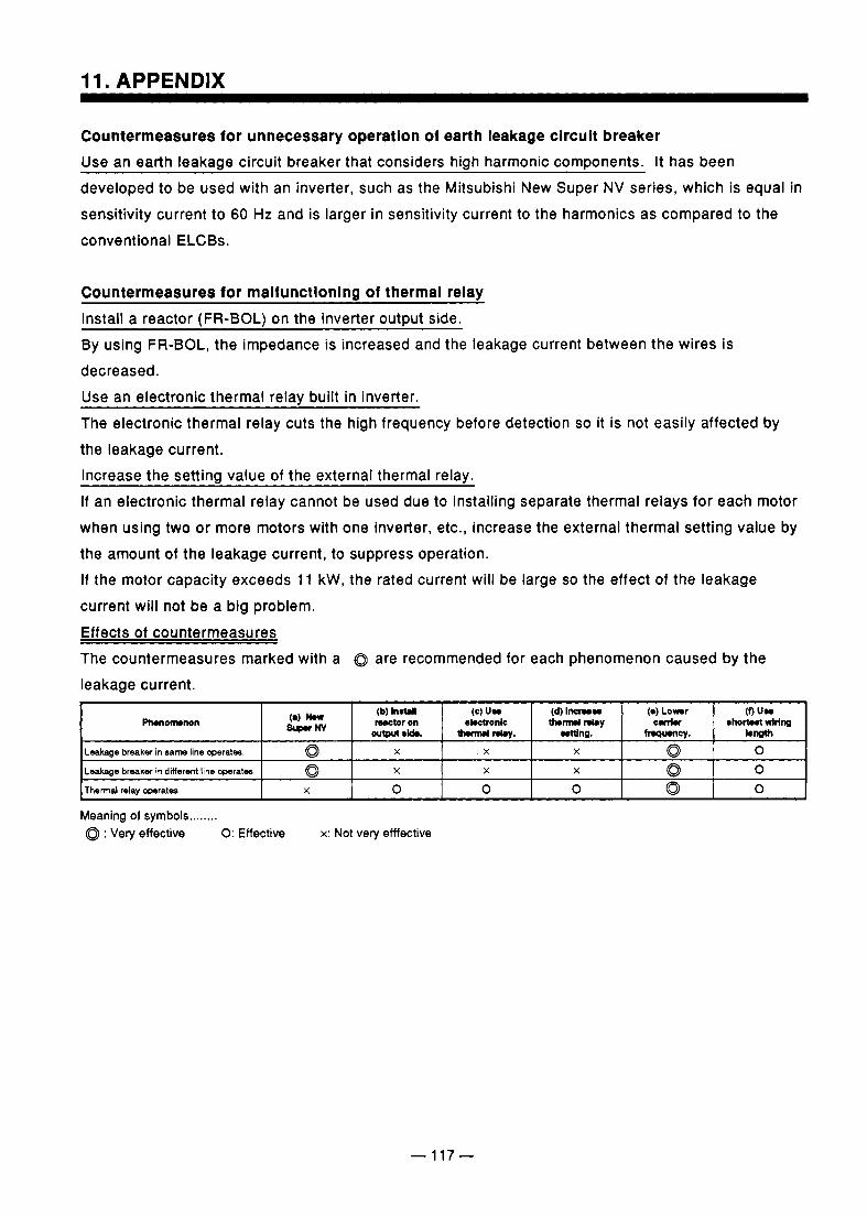
Countermeasures for unnecessary operatlon of earth leakage clrcult breaker Use an earth leakaae circuit breaker that considers hiah harmonic components. It has been developed to be used with an inverter, such as the Mitsubishi New Super NV series, which is equal in sensitivity current to 60 Hz and is larger in sensitivity current to the harmonics as compared to the conventional ELCBs.
Countermeasures for malfunctionlng of thermal relay Install a reactor (FR-BOL) on the inverter output side. By using FR-BOL, the impedance is increased and the leakage current between the wires is decreased. Use an electronic thermal relay built in inverter. The electronic thermal relay cuts the high frequency before detection so it is not easily affected by the leakage current. Increase the setting value of the external thermal relay. If an electronic thermal relay cannot be used due to installing separate thermal relays for each motor when using two or more motors with one inverter, etc., increase the external thermal setting value by the amount of the leakage current, to suppress operation. If the motor capacity exceeds 1 1 kW, the rated current will be large so the effect of the leakage
current will not be a big problem. Effects of countermeasures The countermeasures marked with a Q are recommended for each phenomenon caused by the leakage current.
I Leakage breaker in diftersnt line werates I a I X I X I X I d l 0 I I Thermal relay opsrates. I X I O I O I O I Q I 0 I Meaning of symbols ........ Q : Very effective 0: Effective x: Not very efffective
- 117-
.. .
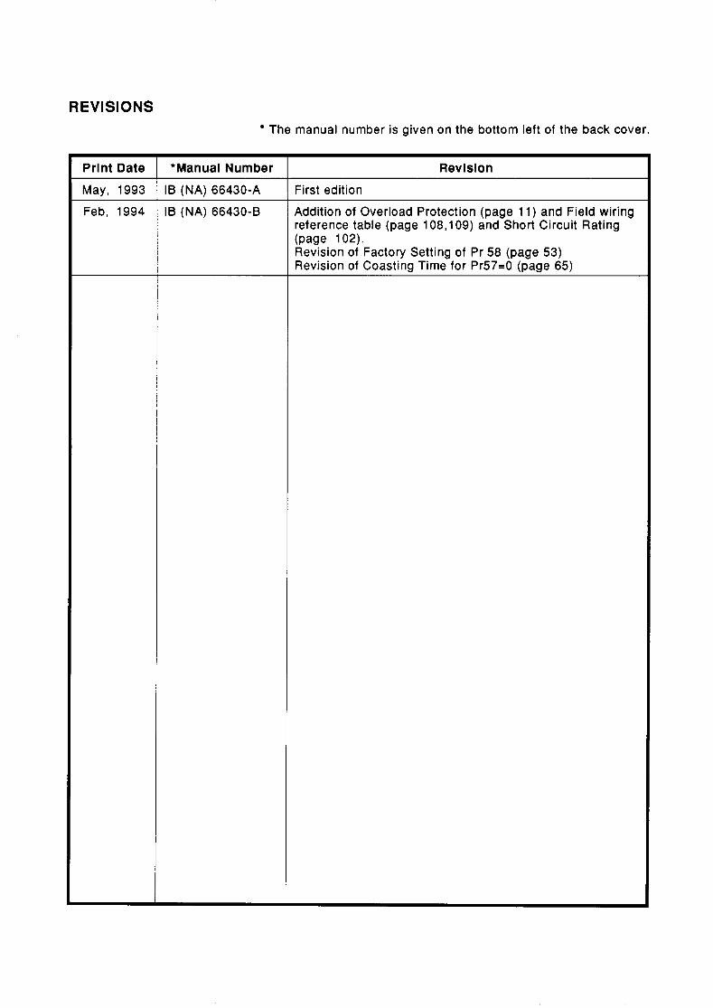
REVISIONS The manual number is given on the bottom left of the back cover.
*Manual Number IB (NA) 66430-A IB (NA) 66430-8
Revision First edition Addition of Overload Protection (page 11) and Field wiring reference table (page 108,109) and Short Circuit Rating (page 1 02). Revision of Factory Setting of Pr 58 (page 53) Revision of Coasting Time for Pr57=0 (page 65)

A MlTSUBlSHl ELECTRIC CORPORATION HEAD OFFICE MlTSUBlSHl DENKl BLDG MARUNOUCHI TOKYO 100
IB (NA) 66430-B (9402) MEE Printed in Japan Specifications subject to change without notice.