Embed Size (px)
Citation preview

CA08104001E For more information, visit: www.eaton.com/consultants
December 2015
Contents
Power Factor Capacitors and Detuned Filters 35.0-1Sheet 35
22
23
24
25
26
27
28
29
30
31
32
33
34
35
36
37
38
39
40
41
42
43
001
Po
we
r Facto
r C
ap
acit
ors
an
d D
etu
ne
d F
ilte
rs Power Factor Capacitors and Detuned Filters
Capacitor Application Considerations
Capacitor Selection . . . . . . . . . . . . . . . . . . . . . . . . . . . . . . . . . . . . . . . . 35.0-2
NEC Code Requirements for Capacitors . . . . . . . . . . . . . . . . . . . . . . . 35.0-2
Capacitor Switching Devices . . . . . . . . . . . . . . . . . . . . . . . . . . . . . . . . 35.0-3
Installing Capacitors in a Plant Distribution System . . . . . . . . . . . . . 35.0-5
Locating Capacitors on Reduced Voltageand Multi-Speed Motor Starters . . . . . . . . . . . . . . . . . . . . . . . . . . . . 35.0-6
Harmonic Considerations. . . . . . . . . . . . . . . . . . . . . . . . . . . . . . . . . . . 35.0-7
Capacitor Banks and Transformers Can Cause Resonance . . . . . . . . 35.0-7
Diagnosing a Potential Harmonics Related Problem . . . . . . . . . . . . . 35.0-8
Motor Power Factor Correction . . . . . . . . . . . . . . . . . . . . . . . . . . . . . . 35.0-9
Capacitor Application Tables for Motors. . . . . . . . . . . . . . . . . . . . . . . 35.0-11
600 Volts AC and Below
Low Voltage Power Factor Correction Capacitor Banks and Detuned Filters
UNIPUMP Power Factor Correction Capacitors . . . . . . . . . . . . . . . . . 35.1-1
Power Factor Correction Capacitors . . . . . . . . . . . . . . . . . . . . . . . . . . 35.1-3
Harmonic Filtering . . . . . . . . . . . . . . . . . . . . . . . . . . . . . . . . . . . . . . . . 35.1-3
UNIPAK Detuned Filter . . . . . . . . . . . . . . . . . . . . . . . . . . . . . . . . . . . . . 35.1-5
Automatic Power Factor Correction Systems
AUTOVAR 300 Wall-Mounted up to 250 kvar . . . . . . . . . . . . . . . . . . . 35.2-1
AUTOVAR 300 Dimensions . . . . . . . . . . . . . . . . . . . . . . . . . . . . . . . . . 35.2-2
AUTOVAR 600 Floor-Mounted up to 1200 kvar. . . . . . . . . . . . . . . . . . 35.2-3
AUTOVAR 600 Dimensions . . . . . . . . . . . . . . . . . . . . . . . . . . . . . . . . . 35.2-8
AUTOVAR Filter . . . . . . . . . . . . . . . . . . . . . . . . . . . . . . . . . . . . . . . . . . . 35.2-10
AUTOVAR Switched Detuned Filter Dimensions . . . . . . . . . . . . . . . . 35.2-12
Active Harmonic Filter-Harmonic Correction Unit
General Description . . . . . . . . . . . . . . . . . . . . . . . . . . . . . . . . . . . . . . . 35.3-1
Dimensions . . . . . . . . . . . . . . . . . . . . . . . . . . . . . . . . . . . . . . . . . . . . . . 35.3-6
Transient-Free Statically Switched Capacitor Bank
General Description . . . . . . . . . . . . . . . . . . . . . . . . . . . . . . . . . . . . . . . 35.4-1
Metal-Enclosed—Medium Voltage
UNIVAR XV (5 kV Class)
General Description . . . . . . . . . . . . . . . . . . . . . . . . . . . . . . . . . . . . . . . 35.5-1
Layout Dimensions . . . . . . . . . . . . . . . . . . . . . . . . . . . . . . . . . . . . . . . . 35.5-3
UNIVAR (15 kV Class)
General Description . . . . . . . . . . . . . . . . . . . . . . . . . . . . . . . . . . . . . . . 35.5-5
Layout Dimensions . . . . . . . . . . . . . . . . . . . . . . . . . . . . . . . . . . . . . . . . 35.5-6
AUTOVAR MV
General Description . . . . . . . . . . . . . . . . . . . . . . . . . . . . . . . . . . . . . . . 35.6-2
Layout Dimensions . . . . . . . . . . . . . . . . . . . . . . . . . . . . . . . . . . . . . . . . 35.6-6
Specifications
See Eaton’s Product Specification Guide, available on CD or on the Web.CSI Format: . . . . . . . . . . . . . . . . . . . . . . . . . . 1995 2010
Fixed Power Factor Correction Equipment—LV (UNIPAK) . . . . . . . . . . . Section 16280A Section 23 35 33.11
Switched Power Factor Correction Equipment—LV (AUTOVAR) . . . . . . . . . . . Section 16280B Section 23 35 33.13
Switched Detuned Filter Equipment—LV (AUTOVAR) . . . . . . . . . Section 16280C Section 26 35 26.11
Switched Capacitor & Detuned Filter Equipment—MV (AUTOVAR) . . . . . . . . . . Section 16280E Section 23 35 33.19
Fixed Detuned Filter Power Factor Correction Equipment—LV (UNIPAK Detuned Filter) . . . . . . . . . . . . Section 16280F Section 26 35 26.13
35.0-2
For more information, visit: www.eaton.com/consultants CA08104001E
December 2015
Power Factor Capacitors and Detuned Filters
Sheet 35
22
23
24
25
26
27
28
29
30
31
32
33
34
35
36
37
38
39
40
41
42
43
Application ConsiderationsCapacitors
002
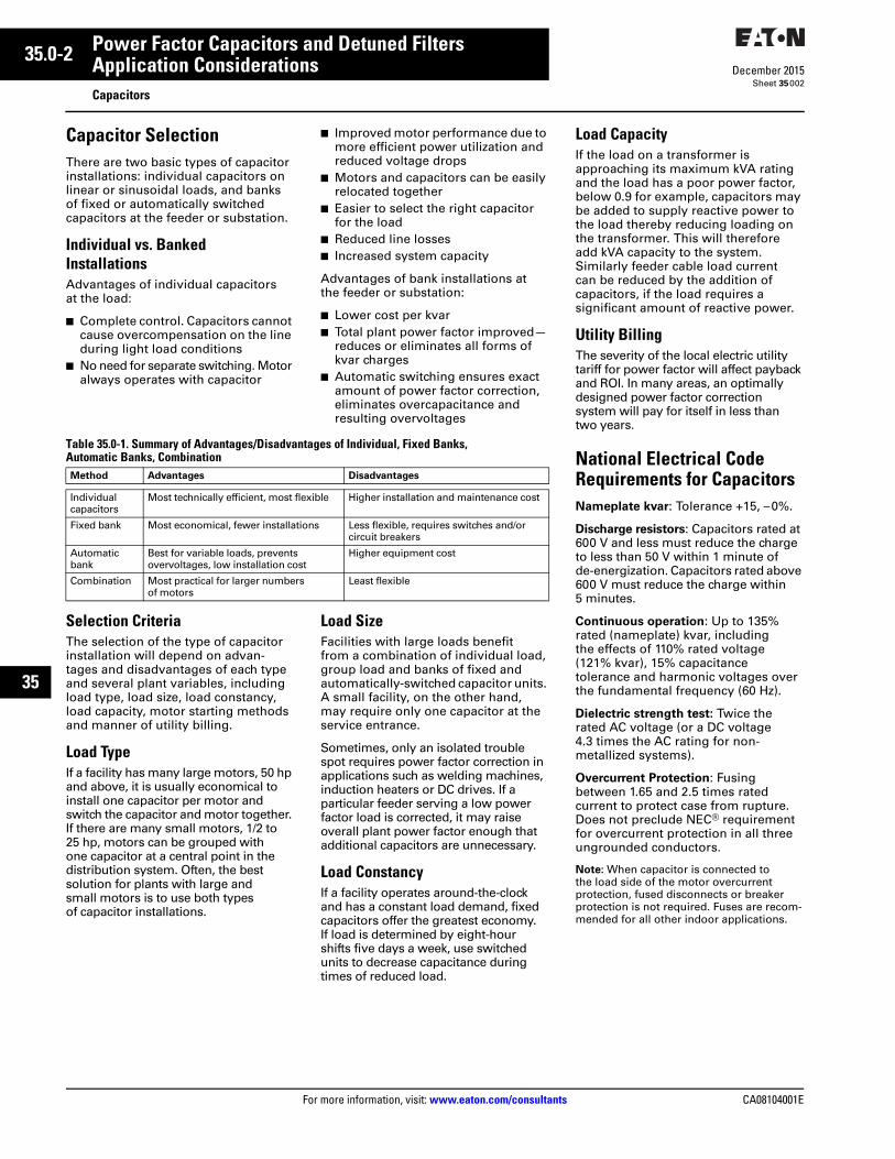
Capacitor SelectionThere are two basic types of capacitor installations: individual capacitors on linear or sinusoidal loads, and banks of fixed or automatically switched capacitors at the feeder or substation.
Individual vs. Banked InstallationsAdvantages of individual capacitors at the load:
■ Complete control. Capacitors cannot cause overcompensation on the line during light load conditions
■ No need for separate switching. Motor always operates with capacitor
■ Improved motor performance due to more efficient power utilization and reduced voltage drops
■ Motors and capacitors can be easily relocated together
■ Easier to select the right capacitor for the load
■ Reduced line losses■ Increased system capacity
Advantages of bank installations at the feeder or substation:
■ Lower cost per kvar■ Total plant power factor improved—
reduces or eliminates all forms of kvar charges
■ Automatic switching ensures exact amount of power factor correction, eliminates overcapacitance and resulting overvoltages
Table 35.0-1. Summary of Advantages/Disadvantages of Individual, Fixed Banks, Automatic Banks, Combination
Selection CriteriaThe selection of the type of capacitor installation will depend on advan-tages and disadvantages of each type and several plant variables, including load type, load size, load constancy, load capacity, motor starting methods and manner of utility billing.
Load TypeIf a facility has many large motors, 50 hp and above, it is usually economical to install one capacitor per motor and switch the capacitor and motor together. If there are many small motors, 1/2 to 25 hp, motors can be grouped with one capacitor at a central point in the distribution system. Often, the best solution for plants with large and small motors is to use both types of capacitor installations.
Load SizeFacilities with large loads benefit from a combination of individual load, group load and banks of fixed and automatically-switched capacitor units. A small facility, on the other hand, may require only one capacitor at the service entrance.
Sometimes, only an isolated trouble spot requires power factor correction in applications such as welding machines, induction heaters or DC drives. If a particular feeder serving a low power factor load is corrected, it may raise overall plant power factor enough that additional capacitors are unnecessary.
Load ConstancyIf a facility operates around-the-clock and has a constant load demand, fixed capacitors offer the greatest economy. If load is determined by eight-hour shifts five days a week, use switched units to decrease capacitance during times of reduced load.
Method Advantages Disadvantages
Individualcapacitors
Most technically efficient, most flexible Higher installation and maintenance cost
Fixed bank Most economical, fewer installations Less flexible, requires switches and/or circuit breakers
Automaticbank
Best for variable loads, prevents overvoltages, low installation cost
Higher equipment cost
Combination Most practical for larger numbers of motors
Least flexible
Load CapacityIf the load on a transformer is approaching its maximum kVA rating and the load has a poor power factor, below 0.9 for example, capacitors may be added to supply reactive power to the load thereby reducing loading on the transformer. This will therefore add kVA capacity to the system. Similarly feeder cable load current can be reduced by the addition of capacitors, if the load requires a significant amount of reactive power.
Utility BillingThe severity of the local electric utility tariff for power factor will affect payback and ROI. In many areas, an optimally designed power factor correction system will pay for itself in less than two years.
National Electrical Code Requirements for CapacitorsNameplate kvar: Tolerance +15, –0%.
Discharge resistors: Capacitors rated at 600 V and less must reduce the charge to less than 50 V within 1 minute of de-energization. Capacitors rated above 600 V must reduce the charge within5 minutes.
Continuous operation: Up to 135% rated (nameplate) kvar, includingthe effects of 110% rated voltage (121% kvar), 15% capacitance tolerance and harmonic voltages over the fundamental frequency (60 Hz).
Dielectric strength test: Twice the rated AC voltage (or a DC voltage 4.3 times the AC rating for non-metallized systems).
Overcurrent Protection: Fusing between 1.65 and 2.5 times rated current to protect case from rupture. Does not preclude NEC® requirement for overcurrent protection in all three ungrounded conductors.
Note: When capacitor is connected to the load side of the motor overcurrent protection, fused disconnects or breaker protection is not required. Fuses are recom-mended for all other indoor applications.
CA08104001E For more information, visit: www.eaton.com/consultants
35.0-3December 2015
Power Factor Capacitors and Detuned Filters
Sheet 35
22
23
24
25
26
27
28
29
30
31
32
33
34
35
36
37
38
39
40
41
42
43
Application ConsiderationsSwitching Devices
003
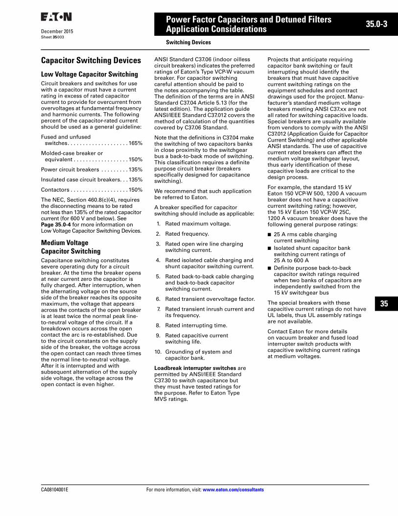
Capacitor Switching Devices
Low Voltage Capacitor SwitchingCircuit breakers and switches for use with a capacitor must have a current rating in excess of rated capacitor current to provide for overcurrent from overvoltages at fundamental frequency and harmonic currents. The following percent of the capacitor-rated current should be used as a general guideline:
Fused and unfused switches. . . . . . . . . . . . . . . . . . . . 165%
Molded-case breaker or equivalent . . . . . . . . . . . . . . . . . . 150%
Power circuit breakers . . . . . . . . . 135%
Insulated case circuit breakers. . . 135%
Contactors . . . . . . . . . . . . . . . . . . . 150%
The NEC, Section 460.8(c)(4), requires the disconnecting means to be rated not less than 135% of the rated capacitor current (for 600 V and below). See Page 35.0-4 for more information on Low Voltage Capacitor Switching Devices.
Medium Voltage Capacitor SwitchingCapacitance switching constitutes severe operating duty for a circuit breaker. At the time the breaker opens at near current zero the capacitor is fully charged. After interruption, when the alternating voltage on the source side of the breaker reaches its opposite maximum, the voltage that appears across the contacts of the open breaker is at least twice the normal peak line-to-neutral voltage of the circuit. If a breakdown occurs across the open contact the arc is re-established. Due to the circuit constants on the supply side of the breaker, the voltage across the open contact can reach three times the normal line-to-neutral voltage. After it is interrupted and with subsequent alternation of the supply side voltage, the voltage across the open contact is even higher.
ANSI Standard C37.06 (indoor oilless circuit breakers) indicates the preferred ratings of Eaton’s Type VCP-W vacuum breaker. For capacitor switching careful attention should be paid to the notes accompanying the table. The definition of the terms are in ANSI Standard C37.04 Article 5.13 (for the latest edition). The application guide ANSI/IEEE Standard C37.012 covers the method of calculation of the quantities covered by C37.06 Standard.
Note that the definitions in C37.04 make the switching of two capacitors banks in close proximity to the switchgear bus a back-to-back mode of switching. This classification requires a definite purpose circuit breaker (breakers specifically designed for capacitance switching).
We recommend that such application be referred to Eaton.
A breaker specified for capacitor switching should include as applicable:
1. Rated maximum voltage.
2. Rated frequency.
3. Rated open wire line charging switching current.
4. Rated isolated cable charging and shunt capacitor switching current.
5. Rated back-to-back cable charging and back-to-back capacitor switching current.
6. Rated transient overvoltage factor.
7. Rated transient inrush current and its frequency.
8. Rated interrupting time.
9. Rated capacitive current switching life.
10. Grounding of system and capacitor bank.
Loadbreak interrupter switches are permitted by ANSI/IEEE Standard C37.30 to switch capacitance but they must have tested ratings for the purpose. Refer to Eaton Type MVS ratings.
Projects that anticipate requiring capacitor bank switching or fault interrupting should identify the breakers that must have capacitive current switching ratings on the equipment schedules and contract drawings used for the project. Manu-facturer’s standard medium voltage breakers meeting ANSI C37.xx are not all rated for switching capacitive loads. Special breakers are usually available from vendors to comply with the ANSI C37.012 (Application Guide for Capacitor Current Switching) and other applicable ANSI standards. The use of capacitive current rated breakers can affect the medium voltage switchgear layout, thus early identification of these capacitive loads are critical to the design process.
For example, the standard 15 kV Eaton 150 VCP-W 500, 1200 A vacuum breaker does not have a capacitive current switching rating; however, the 15 kV Eaton 150 VCP-W 25C, 1200 A vacuum breaker does have the following general purpose ratings:
■ 25 A rms cable charging current switching
■ Isolated shunt capacitor bank switching current ratings of 25 A to 600 A
■ Definite purpose back-to-back capacitor switch ratings required when two banks of capacitors are independently switched from the 15 kV switchgear bus
The special breakers with these capacitive current ratings do not have UL labels, thus UL assembly ratings are not available.
Contact Eaton for more details on vacuum breaker and fused load interrupter switch products with capacitive switching current ratings at medium voltages.
35.0-4
For more information, visit: www.eaton.com/consultants CA08104001E
December 2015
Power Factor Capacitors and Detuned Filters
Sheet 35
22
23
24
25
26
27
28
29
30
31
32
33
34
35
36
37
38
39
40
41
42
43
Application ConsiderationsSwitching Devices
004
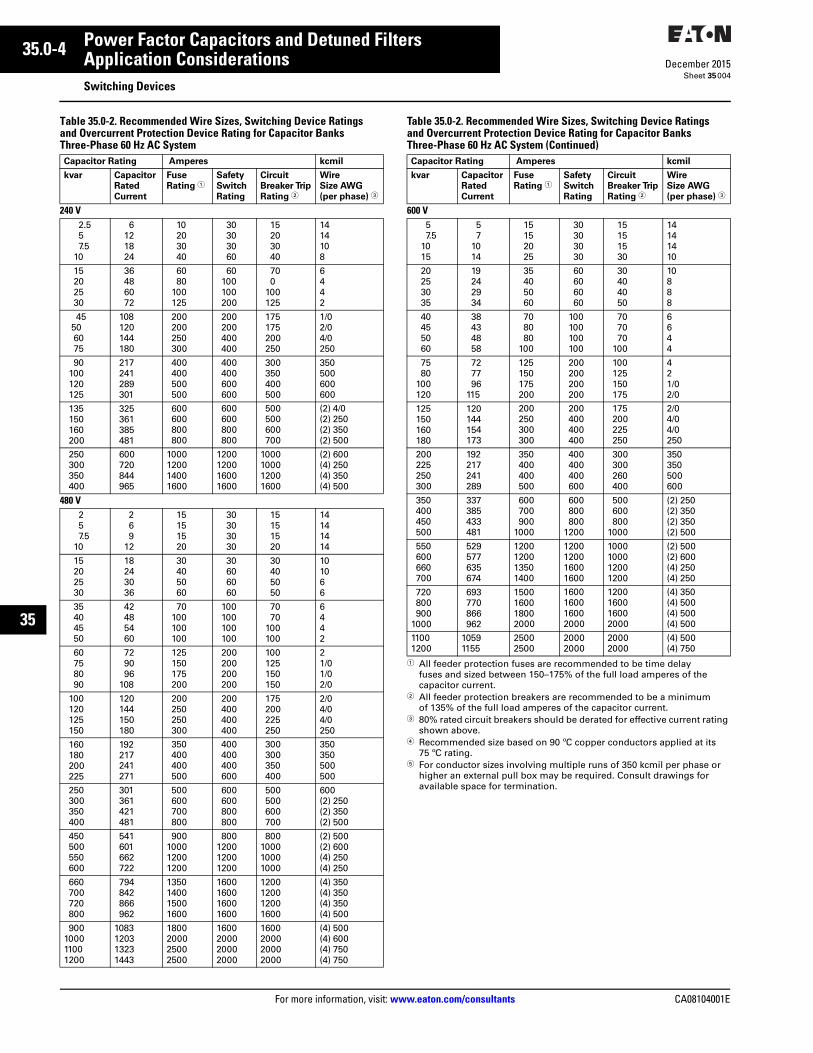
Table 35.0-2. Recommended Wire Sizes, Switching Device Ratings and Overcurrent Protection Device Rating for Capacitor Banks Three-Phase 60 Hz AC System
Table 35.0-2. Recommended Wire Sizes, Switching Device Ratings and Overcurrent Protection Device Rating for Capacitor Banks Three-Phase 60 Hz AC System (Continued)
1 All feeder protection fuses are recommended to be time delay fuses and sized between 150–175% of the full load amperes of the capacitor current.
2 All feeder protection breakers are recommended to be a minimum of 135% of the full load amperes of the capacitor current.
3 80% rated circuit breakers should be derated for effective current rating shown above.
4 Recommended size based on 90 ºC copper conductors applied at its 75 ºC rating.
5 For conductor sizes involving multiple runs of 350 kcmil per phase or higher an external pull box may be required. Consult drawings for available space for termination.
Capacitor Rating Amperes kcmil
kvar Capacitor
Rated
Current
Fuse
Rating 1Safety
Switch
Rating
Circuit
Breaker Trip
Rating 2
Wire
Size AWG
(per phase) 3
240 V2.557.5
10
6121824
10203040
30303060
15203040
1414108
15202530
36486072
6080
100125
60100100200
700
100125
6442
45506075
108120144180
200200250300
200200400400
175175200250
1/02/04/0250
90100120125
217241289301
400400500500
400400600600
300350400500
350500600600
135150160200
325361385481
600600800800
600600800800
500500600700
(2) 4/0(2) 250(2) 350(2) 500
250300350400
600720844965
1000120014001600
1200120016001600
1000100012001600
(2) 600(4) 250(4) 350(4) 500
480 V257.5
10
2 6 912
15151520
30303030
15151520
14141414
15202530
18243036
30405060
30606060
30405050
101066
35404550
42485460
70100100100
100100100100
7070
100100
6442
60758090
729096
108
125150175200
200200200200
100125150150
21/01/02/0
100120125150
120144150180
200250250300
200400400400
175200225250
2/04/04/0250
160180200225
192217241271
350400400500
400400400600
300300350400
350350500500
250300350400
301361421481
500600700800
600600800800
500500600700
600(2) 250(2) 350(2) 500
450500550600
541601662722
900100012001200
800120012001200
800100010001000
(2) 500(2) 600(4) 250(4) 250
660700720800
794842866962
1350140015001600
1600160016001600
1200120012001600
(4) 350(4) 350(4) 350(4) 500
900100011001200
1083120313231443
1800200025002500
1600200020002000
1600200020002000
(4) 500(4) 600(4) 750(4) 750
Capacitor Rating Amperes kcmil
kvar Capacitor
Rated
Current
Fuse
Rating 1Safety
Switch
Rating
Circuit
Breaker Trip
Rating 2
Wire
Size AWG
(per phase) 3
600 V5 7.5
1015
57
1014
15152025
30303030
15151530
14141410
20253035
19242934
35405060
60606060
30404050
10888
40455060
38434858
708080
100
100100100100
707070
100
6644
7580
100120
727796
115
125150175200
200200200200
100125150175
421/02/0
125150160180
120144154173
200250300300
200400400400
175200225250
2/04/04/0250
200225250300
192217241289
350400400500
400400400600
300300260400
350350500600
350400450500
337385433481
600700900
1000
600800800
1200
500600800
1000
(2) 250(2) 350(2) 350(2) 500
550600660700
529577635674
1200120013501400
1200120016001600
1000100012001200
(2) 500(2) 600(4) 250(4) 250
720800900
1000
693770866962
1500160018002000
1600160016002000
1200160016002000
(4) 350(4) 500(4) 500(4) 500
11001200
10591155
25002500
20002000
20002000
(4) 500(4) 750
CA08104001E For more information, visit: www.eaton.com/consultants
35.0-5December 2015
Power Factor Capacitors and Detuned Filters
Sheet 35
22
23
24
25
26
27
28
29
30
31
32
33
34
35
36
37
38
39
40
41
42
43
Application ConsiderationsCapacitor Installation
005
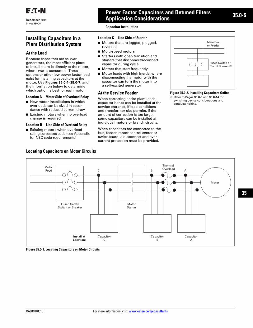
Installing Capacitors in aPlant Distribution System
At the LoadBecause capacitors act as kvar generators, the most efficient place to install them is directly at the motor, where kvar is consumed. Three options or other low power factor load exist for installing capacitors at the motor. Use Figures 35.0-1–35.0-7, and the information below to determine which option is best for each motor.
Location A—Motor Side of Overload Relay■ New motor installations in which
overloads can be sized in accor-dance with reduced current draw
■ Existing motors when no overload change is required
Location B—Line Side of Overload Relay■ Existing motors when overload
rating surpasses code (see Appendix for NEC code requirements)
Location C—Line Side of Starter■ Motors that are jogged, plugged,
reversed■ Multi-speed motors■ Starters with open transition and
starters that disconnect/reconnect capacitor during cycle
■ Motors that start frequently■ Motor loads with high inertia, where
disconnecting the motor with the capacitor can turn the motor into a self-excited generator
At the Service FeederWhen correcting entire plant loads, capacitor banks can be installed at the service entrance, if load conditions and transformer size permits. If the amount of correction is too large, some capacitors can be installed at individual motors or branch circuits.
When capacitors are connected to the bus, feeder, motor control center or switchboard, a disconnect and over-current protection must be provided.
Figure 35.0-2. Installing Capacitors Online1 Refer to Pages 35.0-3 and 35.0-14 for
switching device considerations and conductor sizing.
Locating Capacitors on Motor Circuits
Figure 35.0-1. Locating Capacitors on Motor Circuits
Main Busor Feeder
Fused Switch or Circuit Breaker �
CapacitorBank
Motor
MotorFeed
MotorStarter
Fused SafetySwitch or Breaker
Install atLocation:
CapacitorC
CapacitorB
CapacitorA
Thermal OverloadB AC
35.0-6
For more information, visit: www.eaton.com/consultants CA08104001E
December 2015
Power Factor Capacitors and Detuned Filters
Sheet 35
22
23
24
25
26
27
28
29
30
31
32
33
34
35
36
37
38
39
40
41
42
43
Application ConsiderationsCapacitor Installation
006
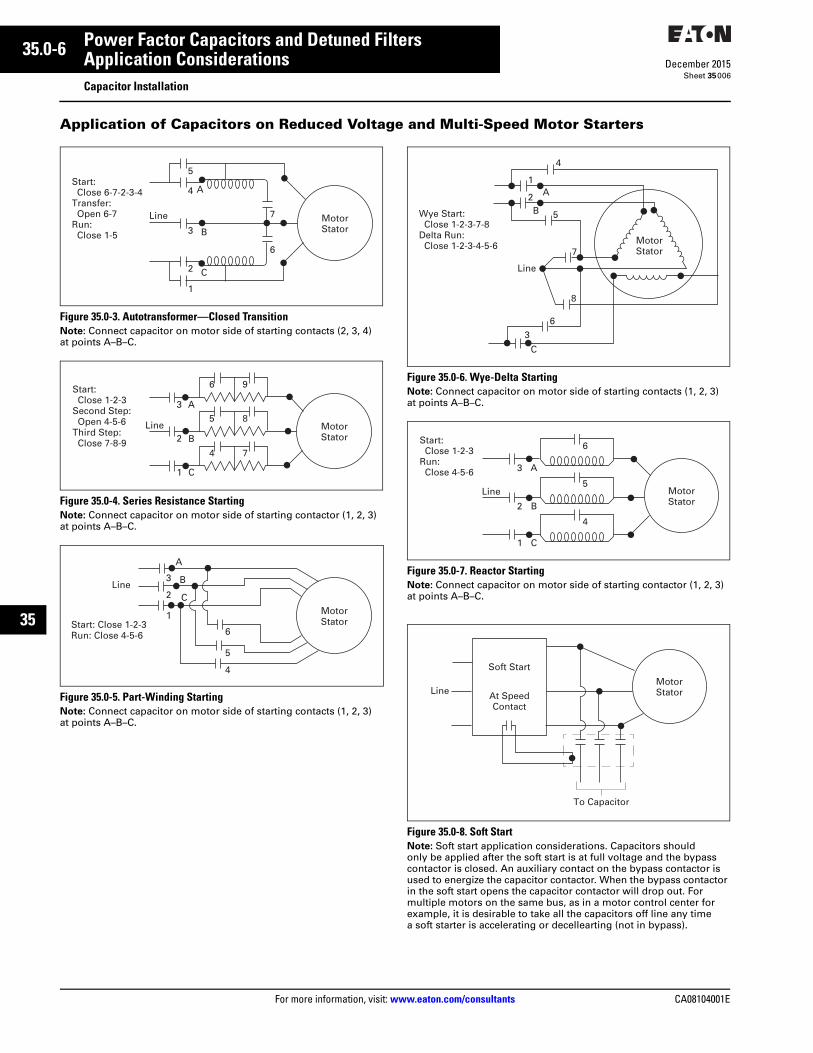
Application of Capacitors on Reduced Voltage and Multi-Speed Motor Starters
Figure 35.0-3. Autotransformer—Closed TransitionNote: Connect capacitor on motor side of starting contacts (2, 3, 4) at points A–B–C.
Figure 35.0-4. Series Resistance StartingNote: Connect capacitor on motor side of starting contactor (1, 2, 3) at points A–B–C.
Figure 35.0-5. Part-Winding StartingNote: Connect capacitor on motor side of starting contacts (1, 2, 3) at points A–B–C.
Figure 35.0-6. Wye-Delta StartingNote: Connect capacitor on motor side of starting contacts (1, 2, 3) at points A–B–C.
Figure 35.0-7. Reactor StartingNote: Connect capacitor on motor side of starting contactor (1, 2, 3) at points A–B–C.
Figure 35.0-8. Soft StartNote: Soft start application considerations. Capacitors shouldonly be applied after the soft start is at full voltage and the bypass contactor is closed. An auxiliary contact on the bypass contactor is used to energize the capacitor contactor. When the bypass contactor in the soft start opens the capacitor contactor will drop out. For multiple motors on the same bus, as in a motor control center for example, it is desirable to take all the capacitors off line any time a soft starter is accelerating or decellearting (not in bypass).
MotorStator
5
4
3
2
1
C
B
A
6
7Line
Start: Close 6-7-2-3-4
Transfer: Open 6-7
Run: Close 1-5
MotorStator
1
2
3 A
B
6 9
5 8
4 7
Line
Start: Close 1-2-3Second Step: Open 4-5-6Third Step: Close 7-8-9
C
MotorStatorStart: Close 1-2-3
Run: Close 4-5-6
A
B
C2
1
3Line
6
5
4
1
2
Line
Wye Start: Close 1-2-3-7-8Delta Run: Close 1-2-3-4-5-6
4
B 5
A
7
8
63
C
MotorStator
MotorStator
A
Line
3
B2
C1
6
5
4
Start: Close 1-2-3Run: Close 4-5-6
MotorStator
To Capacitor
Line
Soft Start
At SpeedContact

CA08104001E For more information, visit: www.eaton.com/consultants
35.0-7December 2015
Power Factor Capacitors and Detuned Filters
Sheet 35
22
23
24
25
26
27
28
29
30
31
32
33
34
35
36
37
38
39
40
41
42
43
Application ConsiderationsHarmonic Considerations
007
Harmonic ConsiderationsA discussion of power system harmonics is incomplete without discussing the effects of power factor correction capacitors. In an industrial plant containing power factor correction capacitors, harmonic currents and voltages can be magnified considerably due to the interaction of the capacitors with the service transformer. This is referred to as harmonic resonance or parallel resonance. For a typical plant containing power factor correction capacitors, the resonant frequency (frequency at which amplification occurs) normally falls in the vicinity of the 5th to the 13th harmonic. Because nonlinear loads typically inject currents at the 5th, 7th, 11th and 13th harmonics, a resonant or near-resonant condition will often result if drives and capacitors are installed on the same system, producing the symptoms and problems with blown fuses, damaged capacitors or failures in other portions of the electrical distribution system.
Note: Capacitors themselves do not cause harmonics, but only aggravate potential harmonic problems. Often, harmonic-related problems do not “show up” until capacitors are applied for power factor correction.
It is a common misconception that the problem of applying capacitors in harmonic environments is limited to problems caused for the capacitor itself—that the capacitor’s lower impedance at higher frequencies causes a current overload into the capacitor and, therefore, must be removed. However, the capacitor/harmonics problem must be viewed from a power system standpoint. The capacitor-induced increase of harmonic voltages and currents on a plant’s system may be causing problems while the capacitor itself remains within its acceptable current rating.
Capacitor Banks and Transformers Can Cause ResonanceCapacitors and transformers can create dangerous resonance conditions when capacitor banks are installed at the service entrance. Under these conditions, harmonics produced by nonlinear devices can be amplified many fold.
Problematic amplification of harmonics becomes more likely as more kvar is added to a system which contains a significant amount of nonlinear load.
An estimate of the resonant harmonic frequency is found by using the following formula:
If h is near the values of the major harmonics generated by a nonlinear device—i.e., 3, 5, 7, 11—then the resonance circuit will greatly increase harmonic distortion.
For example, if a plant has a 1500 kVA transformer with a 5-1/2% impedance and the short-circuit rating of the utility is 48,000 kVA, then kVAsys would equal 17,391 kVA.
If 350 kvar of capacitors were used to improve power factor, h would be:
Because h falls right on the 7th harmonic, these capacitors could create a harmful resonance condition if nonlinear devices were present in the factory. In this case the capacitors should be applied only as detuned filter assemblies.
Eliminating Harmonic ProblemsWhen power factor correction is required in the presence of nonlinear loads, the most reliable, lowest cost solution is often realized with the use of detuned filters.
hkVAsys
kvar-------------------=
kVAsys Short-Circuit Capacity of the System=
h The Harmonic Number referred to a 60 Hz Base=kvar Amount of Capacitor kvar on the Line=
h 17,391350
----------------- 49.7 7.0= = =
35.0-8
For more information, visit: www.eaton.com/consultants CA08104001E
December 2015
Power Factor Capacitors and Detuned Filters
Sheet 35
22
23
24
25
26
27
28
29
30
31
32
33
34
35
36
37
38
39
40
41
42
43
Application ConsiderationsHarmonic Considerations
008
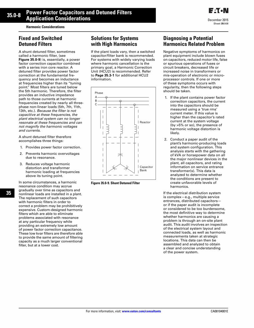
Fixed and Switched Detuned FiltersA shunt detuned filter, sometimes called a harmonic filter, (see Figure 35.0-9) is, essentially, a power factor correction capacitor combined with a series iron core reactor. A detuned filter provides power factor correction at the fundamental fre-quency and becomes an inductance at frequencies higher than its “tuning point.” Most filters are tuned below the 5th harmonic. Therefore, the filter provides an inductive impedance path to those currents at harmonic frequencies created by nearly all three-phase non-linear loads (5th, 7th, 11th, 13th, etc.). Because the filter is not capacitive at these frequencies, the plant electrical system can no longer resonate at these frequencies and can not magnify the harmonic voltages and currents.
A shunt detuned filter therefore accomplishes three things:
1. Provides power factor correction.
2. Prevents harmonic overvoltages due to resonance.
3. Reduces voltage harmonic distortion and transformer harmonic loading at frequencies above its tuning point.
In some circumstances, a harmonicresonance condition may accrue gradually over time as capacitors and nonlinear loads are installed in a plant. The replacement of such capacitors with harmonic filters in order to correct a problem may be prohibitively expensive. Custom-designed harmonic filters which are able to eliminate problems associated with resonance at any particular frequency while providing an extremely low amount of power factor correction capacitance. These low kvar filters are therefore able to provide the same amount of filtering capacity as a much larger conventional filter, but at a lower cost.
Solutions for Systems with High HarmonicsIf the plant loads vary, then a switched capacitor/filter bank is recommended. For systems with widely varying loads where harmonic cancellation is the primary goal, a Harmonic Correction Unit (HCU2) is recommended. Refer to Page 35.3-1 for additional HCU2 information.
Figure 35.0-9. Shunt Detuned Filter
PhaseABC
Reactor
CapacitorBank
Diagnosing a Potential Harmonics Related ProblemNegative symptoms of harmonics on plant equipment include blown fuses on capacitors, reduced motor life, false or spurious operations of fuses or circuit breakers, decreased life or increased noise in transformers or mis-operation of electronic or micro-processor controls. If one or more of these symptoms occurs with regularity, then the following steps should be taken.
1. If the plant contains power factor correction capacitors, the current into the capacitors should be measured using a ‘true rms’ current meter. If this value is higher than the capacitor’s rated current at the system voltage (by >5% or so), the presence of harmonic voltage distortion is likely.
2. Conduct a paper audit of the plant’s harmonic-producing loads and system configuration. This analysis starts with the gathering of kVA or horsepower data on all the major nonlinear devices in the plant, all capacitors, and rating information on service entrance transformer(s). This data is analyzed to determine whether the conditions are present to create unfavorable levels of harmonics.
If the electrical distribution system is complex—e.g., multiple service entrances, distributed capacitors—or if the paper audit is incomplete or considered to be too burdensome, the most definitive way to determine whether harmonics are causing a problem is through an on-site plant audit. This audit involves an inspection of the electrical system layout and connected loads, as well as harmonic measurements taken at strategic locations. This data can then be assembled and analyzed to obtain a clear and concise understanding of the power system.
CA08104001E For more information, visit: www.eaton.com/consultants
35.0-9December 2015
Power Factor Capacitors and Detuned Filters
Sheet 35
22
23
24
25
26
27
28
29
30
31
32
33
34
35
36
37
38
39
40
41
42
43
Application ConsiderationsMotor Power Factor Correction
009
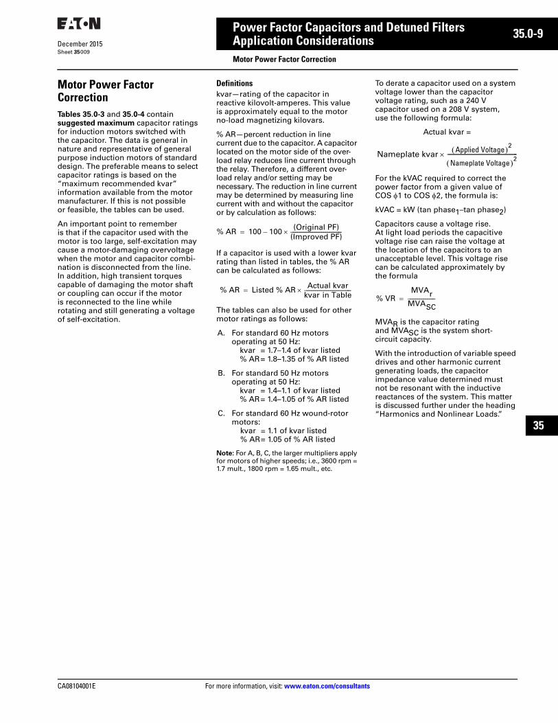
Motor Power Factor CorrectionTables 35.0-3 and 35.0-4 contain suggested maximum capacitor ratings for induction motors switched with the capacitor. The data is general in nature and representative of general purpose induction motors of standard design. The preferable means to select capacitor ratings is based on the “maximum recommended kvar” information available from the motor manufacturer. If this is not possible or feasible, the tables can be used.
An important point to remember is that if the capacitor used with the motor is too large, self-excitation may cause a motor-damaging overvoltage when the motor and capacitor combi-nation is disconnected from the line. In addition, high transient torques capable of damaging the motor shaft or coupling can occur if the motor is reconnected to the line while rotating and still generating a voltage of self-excitation.
Definitionskvar—rating of the capacitor in reactive kilovolt-amperes. This value is approximately equal to the motor no-load magnetizing kilovars.
% AR—percent reduction in line current due to the capacitor. A capacitor located on the motor side of the over-load relay reduces line current through the relay. Therefore, a different over-load relay and/or setting may be necessary. The reduction in line current may be determined by measuring line current with and without the capacitor or by calculation as follows:
If a capacitor is used with a lower kvar rating than listed in tables, the % AR can be calculated as follows:
The tables can also be used for other motor ratings as follows:
A. For standard 60 Hz motors operating at 50 Hz:
kvar = 1.7–1.4 of kvar listed% AR= 1.8–1.35 of % AR listed
B. For standard 50 Hz motors operating at 50 Hz:
kvar = 1.4–1.1 of kvar listed% AR= 1.4–1.05 of % AR listed
C. For standard 60 Hz wound-rotor motors:
kvar = 1.1 of kvar listed% AR= 1.05 of % AR listed
Note: For A, B, C, the larger multipliers apply for motors of higher speeds; i.e., 3600 rpm = 1.7 mult., 1800 rpm = 1.65 mult., etc.
To derate a capacitor used on a system voltage lower than the capacitor voltage rating, such as a 240 V capacitor used on a 208 V system, use the following formula:
For the kVAC required to correct the power factor from a given value of COS 1 to COS 2, the formula is:
kVAC = kW (tan phase1–tan phase2)
Capacitors cause a voltage rise. At light load periods the capacitive voltage rise can raise the voltage at the location of the capacitors to an unacceptable level. This voltage rise can be calculated approximately by the formula
MVAR is the capacitor rating and MVASC is the system short-circuit capacity.
With the introduction of variable speed drives and other harmonic current generating loads, the capacitor impedance value determined must not be resonant with the inductive reactances of the system. This matter is discussed further under the heading “Harmonics and Nonlinear Loads.”
% AR 100 100 (Original PF)(Improved PF)–
% AR Listed % AR Actual kvarkvar in Table
Actual kvar =
Nameplate kvar Applied Voltage 2
Nameplate Voltage 2---------------------------------------------------
% VRMVAr
MVASC
35.0-10
For more information, visit: www.eaton.com/consultants CA08104001E
December 2015
Power Factor Capacitors and Detuned Filters
Sheet 35
22
23
24
25
26
27
28
29
30
31
32
33
34
35
36
37
38
39
40
41
42
43
Application ConsiderationsMotor Power Factor Correction
010
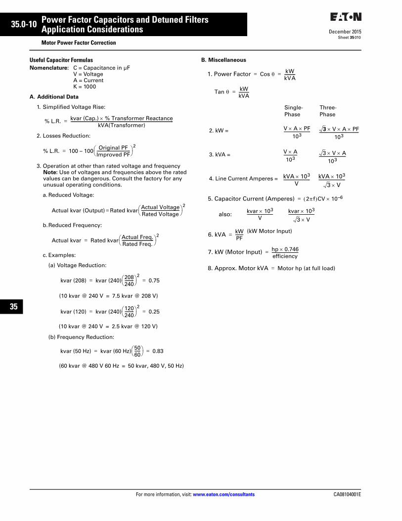
Useful Capacitor FormulasNomenclature: C = Capacitance in µF
V = VoltageA = CurrentK = 1000
A. Additional Data
1. Simplified Voltage Rise:
2. Losses Reduction:
3. Operation at other than rated voltage and frequencyNote: Use of voltages and frequencies above the rated values can be dangerous. Consult the factory for any unusual operating conditions.
a. Reduced Voltage:
b.Reduced Frequency:
c. Examples:
(a) Voltage Reduction:
(b) Frequency Reduction:
B. Miscellaneous
% L.R. kvar (Cap.) % Transformer ReactancekVA(Transformer)
--------------------------------------------------------------------------------------------------------=
% L.R. 100 – 100 Original PFImproved PF---------------------------------- 2
=
Actual kvar (Output) Rated kvar Actual VoltageRated Voltage--------------------------------------- 2
=
Actual kvar Rated kvar Actual Freq.Rated Freq.-------------------------------- 2
=
kvar (208) kvar (240) 208240--------- 2
0.75= =
(10 kvar @ 240 V 7.5 kvar @ 208 V)=
kvar (120) kvar (240) 120240--------- 2
0.25= =
(10 kvar @ 240 V 2.5 kvar @ 120 V)=
kvar (50 Hz) kvar (60 Hz) 5060------ 0.83= =
(60 kvar @ 480 V 60 Hz 50 kvar, 480 V, 50 Hz)=
Single-Phase
Three-Phase
2. kW =
3. kVA =
4. Line Current Amperes =
1. Power Factor Cos kWkVA-----------= =
Tan kWkVA----------=
V A PF103
--------------------------- 3 V A PF103
----------------------------------------
V A103
-------------- 3 V A103
---------------------------
kVA 103V
--------------------------- kVA 1033 V
---------------------------
5. Capacitor Current (Amperes) 2f CV 10–6=
also: kvar 103V
-------------------------- kvar 1033 V
--------------------------
6. kVA kWPF-------- (kW Motor Input)
=
7. kW (Motor Input) hp 0.746efficiency---------------------------=
8. Approx. Motor kVA Motor hp (at full load)=

CA08104001E For more information, visit: www.eaton.com/consultants
35.0-11December 2015
Power Factor Capacitors and Detuned Filters
Sheet 35
22
23
24
25
26
27
28
29
30
31
32
33
34
35
36
37
38
39
40
41
42
43
Application ConsiderationsApplication Considerations—Motors
011
Table 35.0-3. Suggested Maximum Capacitor Ratings
1 For use with three-phase, 60 Hz NEMA Classification B motors to raise full load power factor to approximately 95%.
Induction
Motor hp
Rating
Number of Poles and Nominal Motor Speed in RPM
2—3600 RPM 4—1800 RPM 6—1200 RPM 8—900 RPM 10—720 RPM 12—600 RPM
Capacitor
kvar
Current
Reduction
%
Capacitor
kvar
Current
Reduction
%
Capacitor
kvar
Current
Reduction
%
Capacitor
kvar
Current
Reduction
%
Capacitor
kvar
Current
Reduction
%
Capacitor
kvar
Current
Reduction
%
Used for High Efficiency Motors and Older Design (Pre “T-Frame”) Motors 1
357.5
1.522.5
141211
1.522.5
151312
1.523
201715
234
272522
2.545
353230
346
413734
101520
345
1099
345
111010
356
141312
567.5
211816
689
272321
7.59
12.5
312725
253040
679
988
679
1099
7.59
10
111110
91012.5
151413
1012.515
201816
1517.520
232220
506075
12.51517.5
888
101517.5
988
12.51517.5
101010
1517.520
121110
2022.525
151514
2527.535
191918
100125150
22.527.530
888
202530
888
253035
999
27.53037.5
101010
354050
131312
405050
171615
200250300
405060
888
37.54550
877
405060
988
506060
1099
607080
121111
607590
141312
350400450500
60757575
8888
60607575
7666
75758085
8888
758590
100
9999
9095
100100
101099
95100110120
11111110
T-Frame NEMA® “Design B” Motors 1
235
11.52
141414
11.52.5
242322
1.523
302826
234
423831
234
404040
345
504949
7.51015
2.545
141412
345
201818
456
212120
567.5
282724
57.58
383632
68
10
453834
202530
67.58
121211
67.58
171716
7.58
10
191919
91015
232322
1012.515
292524
12.517.520
303030
405060
12.51517.5
121212
1517.520
161515
152022.5
191917
17.522.525
212120
2022.530
242422
253035
303028
75100125
2022.525
121110
253035
141412
253035
151212
303540
171614
354045
211515
404550
191717
150200250
303540
101011
405060
121110
405060
121110
507080
141413
507090
131313
6090
100
171717
300350400
455075
111210
707580
1088
7590
100
121212
100120130
141313
100120140
131313
120135150
171515
450500
80100
88
90120
89
120150
1012
140160
1212
160180
1413
160180
1515

35.0-12
For more information, visit: www.eaton.com/consultants CA08104001E
December 2015
Power Factor Capacitors and Detuned Filters
Sheet 35
22
23
24
25
26
27
28
29
30
31
32
33
34
35
36
37
38
39
40
41
42
43
Application ConsiderationsApplication Considerations—Motors
012
Table 35.0-4. Suggested Capacitor Ratings, in kvars, for NEMA Design C, D and Wound-Rotor Motors
Note: Applies to three-phase, 60 Hz motors when switched with capacitors as single unit.Note: Use motor manufacturer’s recommended kvar as published in the performance data sheets for specific motor types:drip-proof, TEFC, severe duty, high efficiency and NEMA design.
Table 35.0-5. 2400 Volts and 4160 Volt Motors NEMA Design B
Table 35.0-6. NEMA Design B and C 2300 and 4000 V Motors (after 1956)
Induction Motor Rating (hp)
Design C Motor Design D Motor1200 r/Minimum
Wound-RotorMotor1800 and 1200 r/Minimum 900 r/Minimum
152025
556
566
566
5.577
304050
7.51012
91215
101215
111317.5
6075
100
17.51927
1822.527
1822.530
202533
125150200
3537.545
37.54560
37.54560
405065
250300
5465
7090
7075
7585
Nominal Motor Speed in RPM and Number of Poles
InductionMotorRating (hp)
3600 RPM 2 1800 RPM 4 1200 RPM 6 900 RPM 8 720 RPM 10 600 RPM 12
kvar CurrentReduction %
kvar CurrentReduction %
kvar CurrentReduction %
kvar CurrentReduction %
kvar CurrentReduction %
kvar CurrentReduction %
100120150200
25252550
8777
25252550
10988
25252550
111099
25252550
111099
25252550
12111110
25505075
16151414
250300350400
50505075
7766
50505075
7766
50757575
8887
757575
100
9999
757575
100
10999
75100100100
14131211
450500600700
757575
100
6555
7575
100100
6666
75100100125
6666
100125125150
9988
100125150150
9998
125125150150
10998
800900
10001250
100125150200
5555
150150200200
6666
150200250250
6655
150200250300
7766
200250250300
8876
200250250300
8876
Nominal Motor Speed in RPM and Number of Poles
InductionMotorRating (hp)
3600 RPM 2 1800 RPM 4 1200 RPM 6 900 RPM 8 720 RPM 10 600 RPM 12
kvar CurrentReduction %
kvar CurrentReduction %
kvar CurrentReduction %
kvar CurrentReduction %
kvar CurrentReduction %
kvar CurrentReduction %
NEMA Design B 2300 and 4000 V Motors (after 1956)100120150200250
2525252530
77777
2525252530
109865
2525255050
1110888
2525255050
1110999
2525505075
1211111010
25505075
100
1715151414
300350400450500
5050507575
76555
5050505075
55555
75757575
100
88666
7575
100100125
99988
7575
100100125
99988
100100100100125
12111088
600700800900
10001250
75100100125150200
555555
100100125150200200
555555
100100125200250250
555555
125125150200250300
777666
125150150250250300
888776
125150150250250300
888776
NEMA Design C 2300 and 4000 V Motors (after 1956)100125150200250
—————
—————
2525255050
1111998
2525255050
1111999
2525505050
1111999
2525
———
1111———
—————
—————
300350
——
——
5050
66
7575
98
7575
99
——
——
——
——
CA08104001E For more information, visit: www.eaton.com/consultants
35.0-13December 2015
Power Factor Capacitors and Detuned Filters
Sheet 35
22
23
24
25
26
27
28
29
30
31
32
33
34
35
36
37
38
39
40
41
42
43
Application ConsiderationsApplication Considerations—System kvar Selection
013
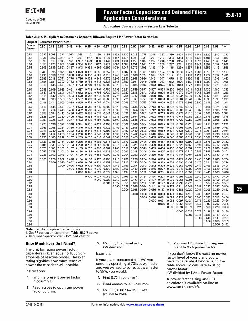
Table 35.0-7. Multipliers to Determine Capacitor Kilovars Required for Power Factor Correction
Note: To obtain required capacitor kvar:1. Get PF correction factor from Table 35.0-7 above.2. Required capacitor kvar = kW load x factor.
How Much kvar Do I Need?The unit for rating power factor capacitors is kvar, equal to 1000 volt-amperes of reactive power. The kvar rating signifies how much reactive power the capacitor will provide.
Instructions:
1. Find the present power factor in column 1.
2. Read across to optimum power factor column.
3. Multiply that number by kW demand.
Example:
If your plant consumed 410 kW, was currently operating at 73% power factor and you wanted to correct power factor to 95%, you would:
1. Find 0.73 in column 1.
2. Read across to 0.95 column.
3. Multiply 0.607 by 410 = 249 (round to 250).
4. You need 250 kvar to bring your plant to 95% power factor.
If you don’t know the existing power factor level of your plant, you will have to calculate it before using the table above. To calculate existing power factor: kW divided by kVA = Power Factor.
A power factor sizing and ROI calculator is available on-line at www.eaton.com/pfc.
Original
Power
Factor
Corrected Power Factor
0.80 0.81 0.82 0.83 0.84 0.85 0.86 0.87 0.88 0.89 0.90 0.91 0.92 0.93 0.94 0.95 0.96 0.97 0.98 0.99 1.0
0.500.510.520.530.54
0.9820.9370.8930.8500.809
1.0080.9620.9190.8760.835
1.0340.9890.9450.9020.861
1.0601.0150.9710.9280.887
1.0861.0410.9970.9540.913
1.1121.0671.0230.9800.939
1.1391.0941.0501.0070.966
1.1651.1201.0761.0330.992
1.1921.1471.1031.0601.019
1.2201.1751.1311.0881.047
1.2481.2031.1591.1161.075
1.2761.2311.1871.1441.103
1.3061.2611.2171.1741.133
1.3371.2921.2481.2051.164
1.3691.3241.2801.2371.196
1.4031.3581.3141.2711.230
1.4401.3951.3511.3081.267
1.4811.4361.3921.3491.308
1.5291.4841.4401.3971.356
1.5891.5441.5001.4571.416
1.7321.6871.6431.6001.559
0.550.560.570.580.59
0.7690.7300.6920.6550.619
0.7950.7560.7180.6810.645
0.8210.7820.7440.7070.671
0.8470.8080.7700.7330.697
0.8730.8340.7960.7590.723
0.8990.8600.8220.7850.749
0.9260.8870.8490.8120.776
0.9520.9130.8750.8380.802
0.9790.9400.9020.8650.829
1.0070.9680.9300.8930.857
1.0350.9960.9580.9210.885
1.0631.0240.9860.9490.913
1.0931.0541.0160.9790.943
1.1241.0851.0471.0100.974
1.1561.1171.0791.0421.006
1.1901.1511.1131.0761.040
1.2271.1881.1501.1131.077
1.2681.2291.1911.1541.118
1.3161.2771.2391.2021.166
1.3761.3371.2991.2621.226
1.5191.4801.4421.4051.369
0.600.610.620.630.64
0.5830.5490.5160.4830.451
0.6090.5750.5420.5090.474
0.6350.6010.5680.5350.503
0.6610.6270.5940.5610.529
0.6870.6530.6200.5870.555
0.7130.6790.6460.6130.581
0.7400.7060.6730.6400.608
0.7660.7320.6990.6660.634
0.7930.7590.7260.6930.661
0.8210.7870.7540.7210.689
0.8490.8150.7820.7490.717
0.8770.8430.8100.7770.745
0.9070.8730.8400.8070.775
0.9380.9040.8710.8380.806
0.9700.9360.9030.8700.838
1.0040.9700.9370.9040.872
1.0411.0070.9740.9410.909
1.0821.0481.0150.9820.950
1.1301.0961.0631.0300.998
1.1901.1561.1231.0901.068
1.3331.2991.2661.2331.201
0.650.660.670.680.69
0.4190.3880.3580.3280.299
0.4450.4140.3840.3540.325
0.4710.4400.4100.3800.351
0.4970.4660.4360.4060.377
0.5230.4920.4620.4320.403
0.5490.5180.4880.4580.429
0.5760.5450.5150.4850.456
0.6020.5710.5410.5110.482
0.6290.5980.5680.5380.509
0.6570.6260.5960.5660.537
0.6850.6540.6240.5940.565
0.7130.6820.6520.6220.593
0.7430.7120.6820.6520.623
0.7740.7430.7130.6830.654
0.8060.7750.7450.7150.686
0.8400.8090.7790.7490.720
0.8770.8460.8160.7860.757
0.9180.8870.8570.8270.798
0.9660.9350.9050.8750.846
1.0260.9950.9650.9350.906
1.1691.1381.1081.0781.049
0.700.710.720.730.74
0.2700.2420.2140.1860.159
0.2960.2680.2400.2120.185
0.3220.2940.2660.2380.211
0.3480.3200.2920.2640.237
0.3740.3460.3180.2900.263
0.4000.3720.3440.3160.289
0.4270.3990.3710.3430.316
0.4530.4250.3970.3690.342
0.4800.4520.4240.3960.369
0.5080.4800.4520.4240.397
0.5360.5080.4800.4520.425
0.5640.5360.5080.4800.453
0.5940.5660.5380.5100.483
0.6250.5970.5690.5410.514
0.6570.6290.6010.5730.546
0.6910.6630.6350.6070.580
0.7280.7000.6720.6440.617
0.7690.7410.7130.6850.658
0.8170.7890.7610.7330.706
0.8770.8490.8210.7930.766
1.0200.9920.9640.9360.909
0.750.760.770.780.79
0.1320.1050.0790.0520.026
0.1580.1310.1050.0780.052
0.1840.1570.1310.1040.078
0.2100.1830.1570.1300.104
0.2360.2090.1830.1560.130
0.2620.2350.2090.1820.156
0.2890.2620.2360.2090.183
0.3150.2880.2620.2350.209
0.3420.3150.2890.2620.236
0.3700.3430.3170.2900.264
0.3980.3710.3450.3180.292
0.4260.3990.3730.3460.320
0.4560.4290.4030.3760.350
0.4870.4600.4340.4070.381
0.5190.4920.4660.4390.413
0.5530.5260.5000.4730.447
0.5900.5630.5370.5100.484
0.6310.6040.5780.5510.525
0.6790.6520.6260.5990.573
0.7390.7120.6850.6590.633
0.8820.8550.8290.8020.776
0.800.810.820.830.84
0.000 0.0260.000
0.0520.0260.000
0.0780.0520.0260.000
0.1040.0780.0520.0260.000
0.1300.1040.0780.0520.026
0.1570.1310.1050.0790.053
0.1830.1570.1310.1050.079
0.2100.1840.1580.1320.106
0.2380.2120.1860.1600.134
0.2660.2400.2140.1880.162
0.2940.2680.2420.2160.190
0.3240.2980.2720.2460.220
0.3550.3290.3030.2770.251
0.3870.3610.3350.3090.283
0.4210.3950.3690.3430.317
0.4580.4320.4060.3800.354
0.4990.4730.4470.4210.395
0.5470.5210.4950.4690.443
0.6090.5810.5550.5290.503
0.7500.7240.6980.6720.646
0.850.860.870.880.89
0.000 0.0270.000
0.0530.0260.000
0.0800.0530.0270.000
0.1080.0810.0550.0280.000
0.1360.1090.0830.0560.028
0.1640.1370.1110.0840.056
0.1940.1670.1410.1140.086
0.2250.1980.1720.1450.117
0.2570.2300.2040.1770.149
0.2910.2640.2380.2110.183
0.3280.3010.2750.2480.220
0.3690.3420.3160.2890.261
0.4170.3900.3640.3370.309
0.4770.4500.4240.3970.369
0.6200.5930.5670.5400.512
0.900.910.920.930.94
0.000 0.0280.000
0.0580.0300.000
0.0890.0610.0310.000
0.1210.0930.0630.0320.000
0.1550.1270.0970.0660.034
0.1920.1640.1340.1030.071
0.2330.2050.1750.1440.112
0.2810.2530.2230.1920.160
0.3410.3130.2830.2520.220
0.4840.4560.4260.3950.363
0.950.960.970.980.99
0.000 0.0370.000
0.0790.0410.000
0.1260.0890.0480.000
0.1860.1490.1080.0600.000
0.3290.2920.2510.2030.143

35.0-14
For more information, visit: www.eaton.com/consultants CA08104001E
December 2015
Power Factor Capacitors and Detuned Filters
Sheet 35
22
23
24
25
26
27
28
29
30
31
32
33
34
35
36
37
38
39
40
41
42
43
014
This page intentionally left blank.
CA08104001E For more information, visit: www.eaton.com/consultants
35.1-1December 2015
Power Factor Capacitors and Detuned Filters
Sheet 35
22
23
24
25
26
27
28
29
30
31
32
33
34
35
36
37
38
39
40
41
42
43
600 Volts AC and BelowGeneral Description
015
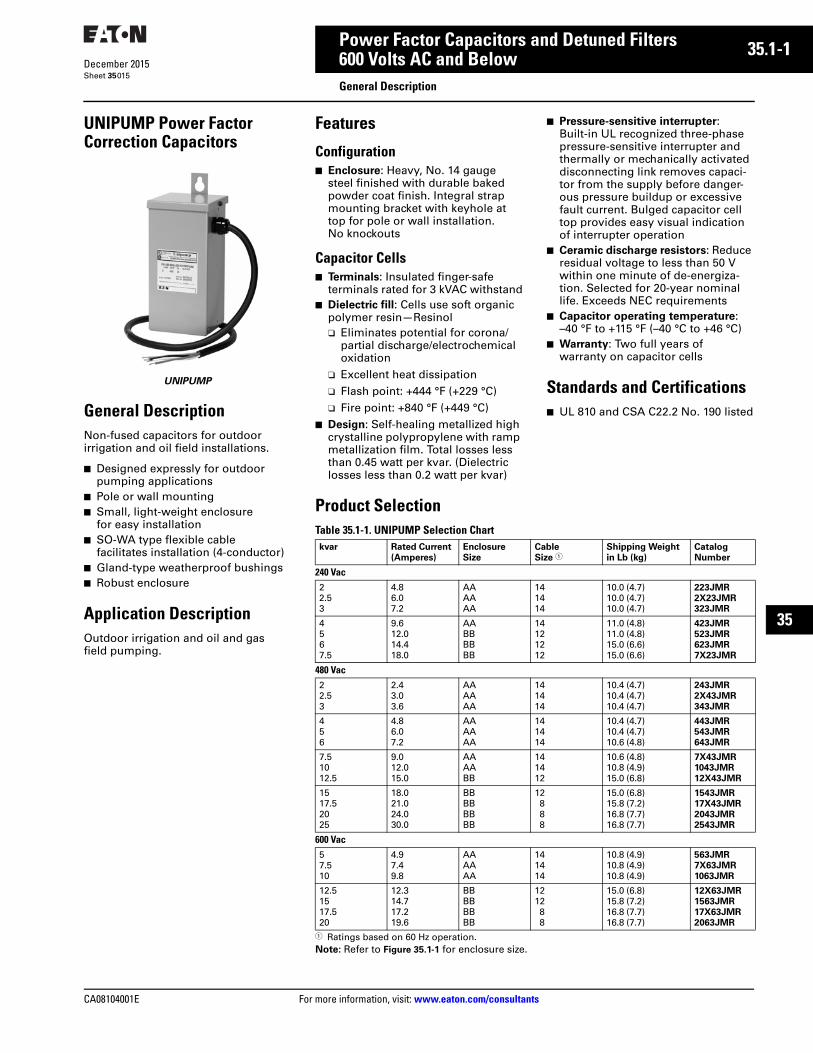
UNIPUMP Power Factor Correction Capacitors
UNIPUMP
General DescriptionNon-fused capacitors for outdoor irrigation and oil field installations.
■ Designed expressly for outdoor pumping applications
■ Pole or wall mounting■ Small, light-weight enclosure
for easy installation■ SO-WA type flexible cable
facilitates installation (4-conductor)■ Gland-type weatherproof bushings■ Robust enclosure
Application DescriptionOutdoor irrigation and oil and gas field pumping.
Features
Configuration■ Enclosure: Heavy, No. 14 gauge
steel finished with durable baked powder coat finish. Integral strap mounting bracket with keyhole at top for pole or wall installation. No knockouts
Capacitor Cells■ Terminals: Insulated finger-safe
terminals rated for 3 kVAC withstand■ Dielectric fill: Cells use soft organic
polymer resin—Resinol❑ Eliminates potential for corona/
partial discharge/electrochemical oxidation
❑ Excellent heat dissipation❑ Flash point: +444 °F (+229 °C)❑ Fire point: +840 °F (+449 °C)
■ Design: Self-healing metallized high crystalline polypropylene with ramp metallization film. Total losses less than 0.45 watt per kvar. (Dielectric losses less than 0.2 watt per kvar)
■ Pressure-sensitive interrupter: Built-in UL recognized three-phase pressure-sensitive interrupter and thermally or mechanically activated disconnecting link removes capaci-tor from the supply before danger-ous pressure buildup or excessive fault current. Bulged capacitor cell top provides easy visual indication of interrupter operation
■ Ceramic discharge resistors: Reduce residual voltage to less than 50 V within one minute of de-energiza-tion. Selected for 20-year nominal life. Exceeds NEC requirements
■ Capacitor operating temperature: –40 °F to +115 °F (–40 °C to +46 °C)
■ Warranty: Two full years of warranty on capacitor cells
Standards and Certifications■ UL 810 and CSA C22.2 No. 190 listed
Product SelectionTable 35.1-1. UNIPUMP Selection Chart
1 Ratings based on 60 Hz operation.Note: Refer to Figure 35.1-1 for enclosure size.
kvar Rated Current
(Amperes)
Enclosure
Size
Cable
Size 1Shipping Weight
in Lb (kg)
Catalog
Number
240 Vac22.53
4.86.07.2
AAAAAA
141414
10.0 (4.7)10.0 (4.7)10.0 (4.7)
223JMR
2X23JMR
323JMR
4567.5
9.612.014.418.0
AABBBBBB
14121212
11.0 (4.8)11.0 (4.8)15.0 (6.6)15.0 (6.6)
423JMR
523JMR
623JMR
7X23JMR
480 Vac22.53
2.43.03.6
AAAAAA
141414
10.4 (4.7)10.4 (4.7)10.4 (4.7)
243JMR
2X43JMR
343JMR
456
4.86.07.2
AAAAAA
141414
10.4 (4.7)10.4 (4.7)10.6 (4.8)
443JMR
543JMR
643JMR
7.51012.5
9.012.015.0
AAAABB
141412
10.6 (4.8)10.8 (4.9)15.0 (6.8)
7X43JMR
1043JMR
12X43JMR
1517.52025
18.021.024.030.0
BBBBBBBB
12888
15.0 (6.8)15.8 (7.2)16.8 (7.7)16.8 (7.7)
1543JMR
17X43JMR
2043JMR
2543JMR
600 Vac57.510
4.97.49.8
AAAAAA
141414
10.8 (4.9)10.8 (4.9)10.8 (4.9)
563JMR
7X63JMR
1063JMR
12.51517.520
12.314.717.219.6
BBBBBBBB
121288
15.0 (6.8)15.8 (7.2)16.8 (7.7)16.8 (7.7)
12X63JMR
1563JMR
17X63JMR
2063JMR
35.1-2
For more information, visit: www.eaton.com/consultants CA08104001E
December 2015
Power Factor Capacitors and Detuned Filters
Sheet 35
22
23
24
25
26
27
28
29
30
31
32
33
34
35
36
37
38
39
40
41
42
43
600 Volts AC and BelowDimensions
016
Dimensions
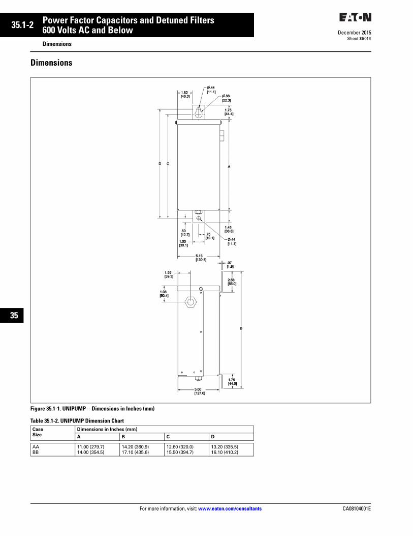
Figure 35.1-1. UNIPUMP—Dimensions in Inches (mm)
Table 35.1-2. UNIPUMP Dimension Chart Case
Size
Dimensions in Inches (mm)
A B C D
AABB
11.00 (279.7)14.00 (354.5)
14.20 (360.9)17.10 (435.6)
12.60 (320.0)15.50 (394.7)
13.20 (335.5)16.10 (410.2)

CA08104001E For more information, visit: www.eaton.com/consultants
35.1-3December 2015
Power Factor Capacitors and Detuned Filters
Sheet 35
22
23
24
25
26
27
28
29
30
31
32
33
34
35
36
37
38
39
40
41
42
43
600 Volts AC and BelowGeneral Description
017
Low Voltage Power Factor Correction Capacitor Banks and Detuned Filters
Low Voltage Power Factor Correction Capacitor Banks and Detuned Filters
General Description
Power Factor Correction CapacitorsEaton Power factor correctioncapacitors and detuned filters are an essential part of modern electric power systems. Power factor correction capacitors are the simplest and most economical means of increasing the capacity of any power system, minimizing energy losses and correcting load power factor. In addition, power factor penalties can be reduced and power quality can be greatly enhanced.
There are several reasons to correct poor power factor. The first is to reduce or eliminate a power factor penalty charged by the utility. Another reason is that your existing transformer is, or shortly will be, at full capacity and installing power factor correction capacitors can be a very cost-effective solution compared to installing a brand new service. Depending on the amount of power factor correction (kvar that needs to be injected into the electrical system to improve the power factor) and the dynamic nature of the load, a fixed or switched capacitor bank may be the best solution. When capacity becomes a problem, the choice of a solution will be dependent upon the size of the increase needed. Like all power quality solutions, there are many factors that need to be considered when determining which solution will be best to solve your power factor problem.
Note: Images contained in this document may be shown with optional components and features not included as part of the base offering.
Harmonic FilteringAs the world becomes more dependent on electric and electronic equipment, the likelihood that the negative impact of harmonic distortion increases dramatically. The efficiency and productivity gains from these increasingly sophisticated pieces of equipment have a negative side effect…increased harmonic distortion in the power lines. The difficult thing about harmonic distortion is determin-ing the cause. Once this has been determined, the solution can be easy. Active harmonic filtering equipment will mitigate specific harmonic issues, and correct poor power factor as well.
Standard UNIPAK Capacitor Banks
Features, Benefits and Functions■ Five-year warranty on capacitor cells
(units with heavy-duty cells)■ Two-year warranty on capacitor cells
(units with standard-duty cells)■ Designed for heavy-duty applications■ Indoor/outdoor service■ Wall (up to C2 enclosure size) and
floor-mounted units available■ Individual cells are internally
protected through the use of an overpressure disconnector and thermal element
■ Quick lead times■ Detuned filters available■ Slim profile allows reduced footprint,
conserving valuable floor space■ Main incoming lugs for copper
cable standard
Configuration■ Outer case: Heavy, No. 14 gauge
steel finished with durable baked powder coat finish. Wall-mounting flanges and floor-mounting feet. Elimination of knockouts permits indoor/outdoor use. Manufactured to NEMA requirements 1 and 3R
■ Elevated floor-mounting feet allow access for easy maintenance
■ Cover: “L” shaped gasketed cover with multiple fasteners provides front opening for ease of installation and service
■ Ground terminal: Furnished inside case
■ Power terminal lugs: Large size provided for easy connection
■ Options:❑ Non-fused units available,
selected sizes❑ Heavy-duty capacitor cells,
selected sizes■ Standard fusing:
❑ Size Code A1: Three midget-type fuses with 100,000 ampere inter-rupting capacity
❑ Size Code A2 and larger: Slotted-blade type fuses with 200,000 A interrupting capacity; fuses mounted on stand-off bushings; solderless connectors for easy hookup of incoming line conductors
❑ Fuse indicating lights: Red, neon blown-fuse indicating lights are protected by transparent weather-proof guard
35.1-4
For more information, visit: www.eaton.com/consultants CA08104001E
December 2015
Power Factor Capacitors and Detuned Filters
Sheet 35
22
23
24
25
26
27
28
29
30
31
32
33
34
35
36
37
38
39
40
41
42
43
600 Volts AC and BelowGeneral Description
018
Capacitor Cells■ Terminals: Insulated finger-safe
terminals rated for 3 kVAC withstand■ Dielectric fill: Cells use soft organic
polymer resin—Resinol❑ Eliminates potential for corona/
partial discharge/electrochemical oxidation
❑ Excellent heat dissipation❑ Flash point: +444 °F (+229 °C)❑ Fire point: +840 °F (+449 °C)
■ Design: Self-healing metallized high crystalline polypropylene with metallization film. Dielectric losses less than 0.2 watt per kvar
■ Total capacitor cell heat loss: Total losses less than 0.45 watt per kvar including discharge resistor
■ Pressure-sensitive interrupter: Built-in UL recognized three-phase pressure-sensitive interrupter and thermally or mechanically activated disconnecting link removes capaci-tor from the supply before danger-ous pressure buildup or excessive fault current. Bulged capacitor cell top provides easy visual indication of interrupter operation
■ Ceramic discharge resistors: Reduce residual voltage to less than 50 V within one minute of de-energiza-tion. Selected for 20-year nominal life. Exceeds NEC requirements
■ Capacitor operating temperature: –40 °F to +115 °F (–40 °C to +46 °C)
■ Capacitor cell case: Weatherproof aluminum housing
■ Warranty: The longest in the industry—five full years of warranty on capacitor cells (units with heavy-duty cells); units with standard-duty cells have a two-year warranty on capacitor cells
Heavy-duty capacitor cells■ For use in moderate harmonic
environments where engineering evaluation allows in place of detuned filter designs
■ Provides future conversion capability into a detuned filter system when required by facility growth of increased nonlinear load levels
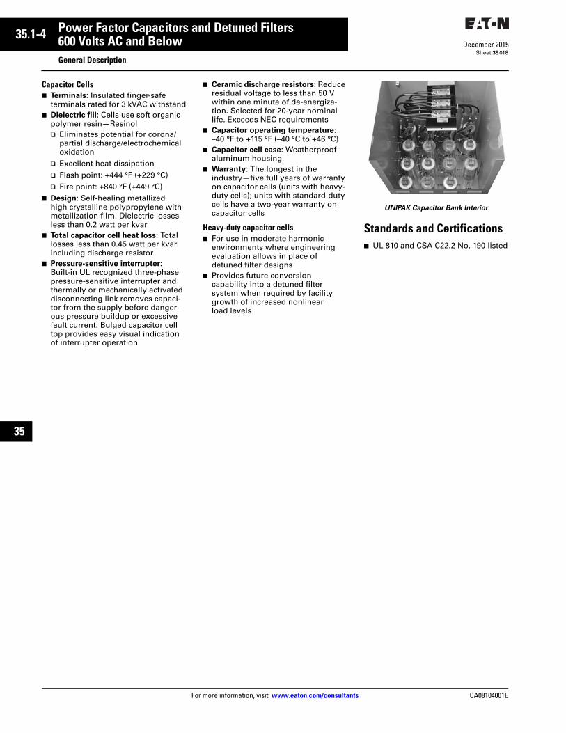
UNIPAK Capacitor Bank Interior
Standards and Certifications■ UL 810 and CSA C22.2 No. 190 listed
CA08104001E For more information, visit: www.eaton.com/consultants
35.1-5December 2015
Power Factor Capacitors and Detuned Filters
Sheet 35
22
23
24
25
26
27
28
29
30
31
32
33
34
35
36
37
38
39
40
41
42
43
600 Volts AC and BelowGeneral Description
019
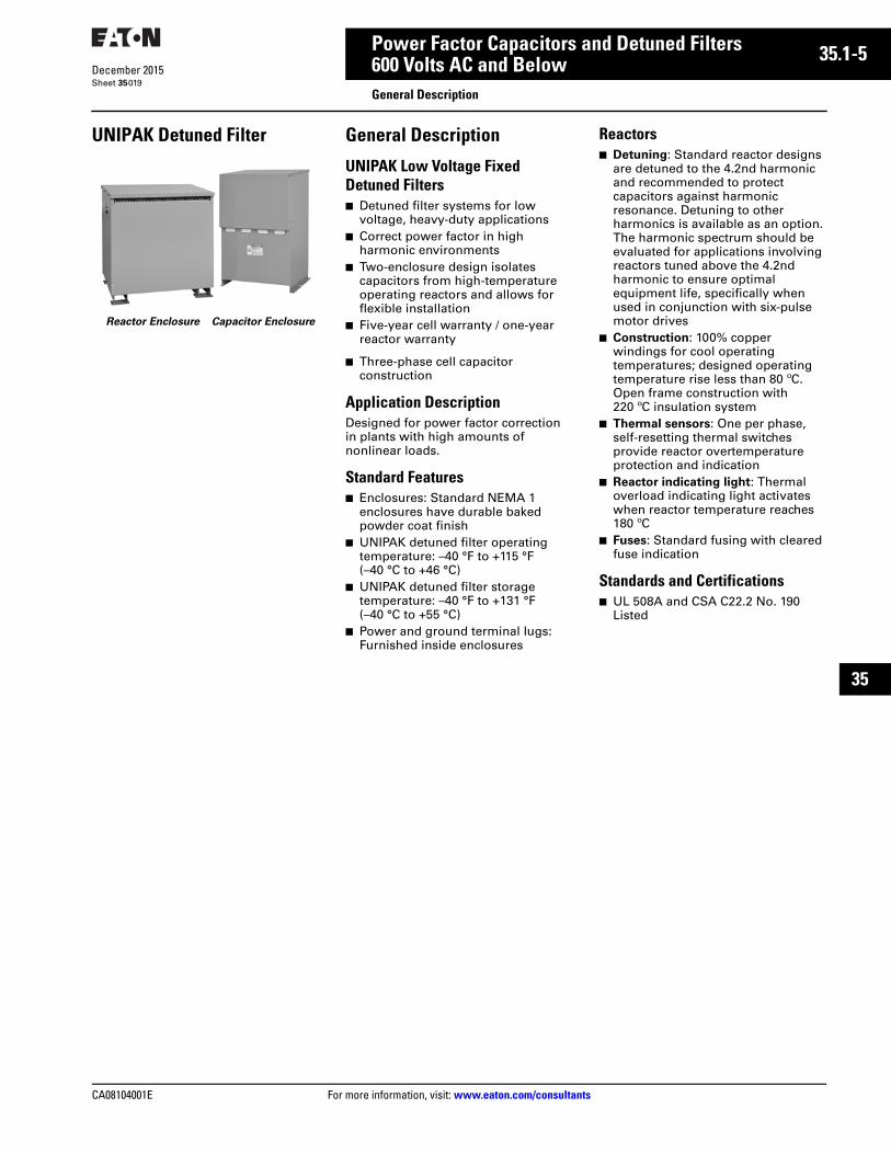
UNIPAK Detuned Filter
Reactor Enclosure Capacitor Enclosure
General Description
UNIPAK Low Voltage Fixed Detuned Filters■ Detuned filter systems for low
voltage, heavy-duty applications■ Correct power factor in high
harmonic environments■ Two-enclosure design isolates
capacitors from high-temperature operating reactors and allows for flexible installation
■ Five-year cell warranty / one-year reactor warranty
■ Three-phase cell capacitor construction
Application DescriptionDesigned for power factor correction in plants with high amounts of nonlinear loads.
Standard Features■ Enclosures: Standard NEMA 1
enclosures have durable baked powder coat finish
■ UNIPAK detuned filter operating temperature: –40 °F to +115 °F (–40 °C to +46 °C)
■ UNIPAK detuned filter storage temperature: –40 °F to +131 °F (–40 °C to +55 °C)
■ Power and ground terminal lugs: Furnished inside enclosures
Reactors■ Detuning: Standard reactor designs
are detuned to the 4.2nd harmonic and recommended to protect capacitors against harmonic resonance. Detuning to other harmonics is available as an option. The harmonic spectrum should be evaluated for applications involving reactors tuned above the 4.2nd harmonic to ensure optimal equipment life, specifically when used in conjunction with six-pulse motor drives
■ Construction: 100% copper windings for cool operating temperatures; designed operating temperature rise less than 80 ºC. Open frame construction with 220 ºC insulation system
■ Thermal sensors: One per phase, self-resetting thermal switches provide reactor overtemperature protection and indication
■ Reactor indicating light: Thermal overload indicating light activates when reactor temperature reaches 180 ºC
■ Fuses: Standard fusing with cleared fuse indication
Standards and Certifications■ UL 508A and CSA C22.2 No. 190
Listed
35.1-6
For more information, visit: www.eaton.com/consultants CA08104001E
December 2015
Power Factor Capacitors and Detuned Filters
Sheet 35
22
23
24
25
26
27
28
29
30
31
32
33
34
35
36
37
38
39
40
41
42
43
600 Volts AC and BelowTechnical Data
020
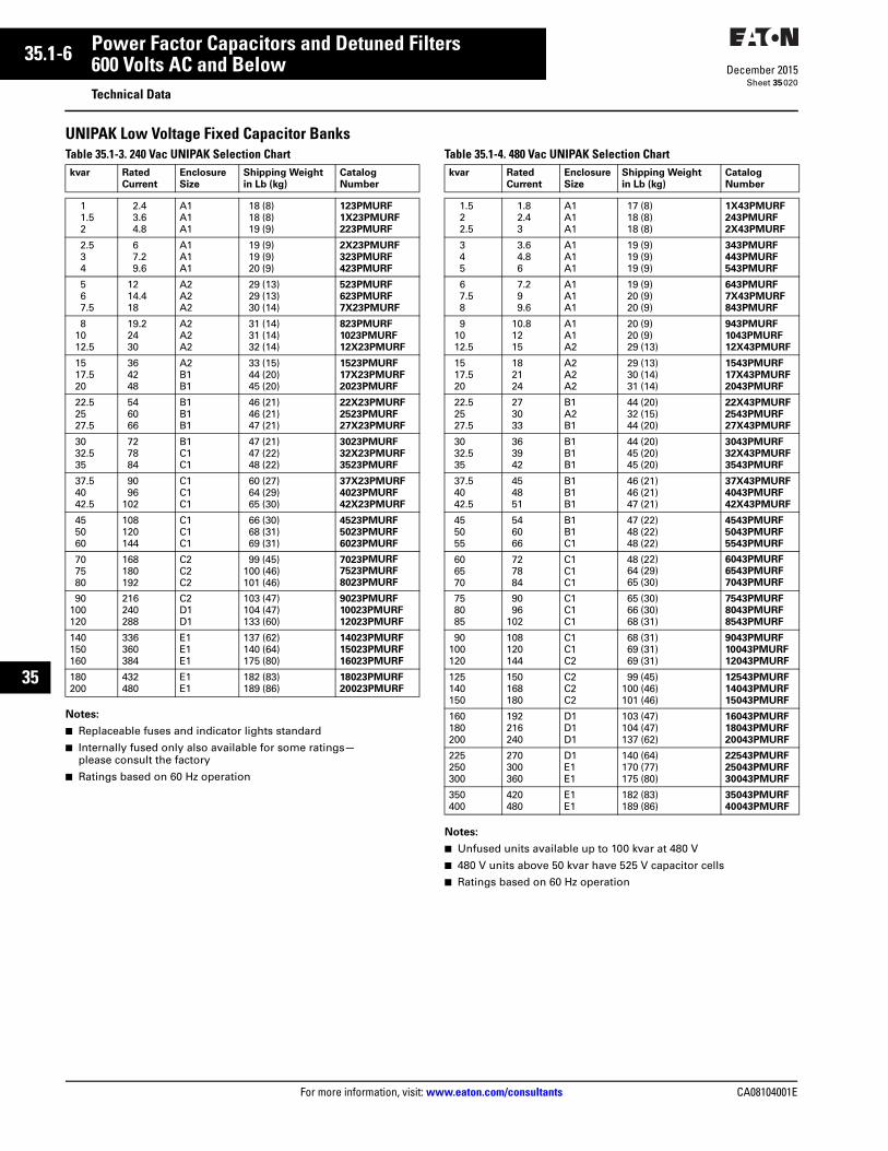
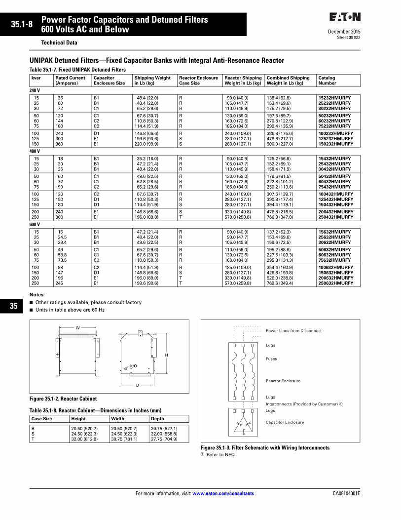
UNIPAK Low Voltage Fixed Capacitor Banks Table 35.1-3. 240 Vac UNIPAK Selection Chart
Notes:
■ Replaceable fuses and indicator lights standard
■ Internally fused only also available for some ratings—please consult the factory
■ Ratings based on 60 Hz operation
Table 35.1-4. 480 Vac UNIPAK Selection Chart
Notes:
■ Unfused units available up to 100 kvar at 480 V
■ 480 V units above 50 kvar have 525 V capacitor cells
■ Ratings based on 60 Hz operation
kvar Rated
Current
Enclosure
Size
Shipping Weight
in Lb (kg)
Catalog
Number
11.52
2.43.64.8
A1A1A1
18 (8)18 (8)19 (9)
123PMURF
1X23PMURF
223PMURF
2.534
67.29.6
A1A1A1
19 (9)19 (9)20 (9)
2X23PMURF
323PMURF
423PMURF
567.5
1214.418
A2A2A2
29 (13)29 (13)30 (14)
523PMURF
623PMURF
7X23PMURF
81012.5
19.22430
A2A2A2
31 (14)31 (14)32 (14)
823PMURF
1023PMURF
12X23PMURF
1517.520
364248
A2B1B1
33 (15)44 (20)45 (20)
1523PMURF
17X23PMURF
2023PMURF
22.52527.5
546066
B1B1B1
46 (21)46 (21)47 (21)
22X23PMURF
2523PMURF
27X23PMURF
3032.535
727884
B1C1C1
47 (21)47 (22)48 (22)
3023PMURF
32X23PMURF
3523PMURF
37.54042.5
9096
102
C1C1C1
60 (27)64 (29)65 (30)
37X23PMURF
4023PMURF
42X23PMURF
455060
108120144
C1C1C1
66 (30)68 (31)69 (31)
4523PMURF
5023PMURF
6023PMURF
707580
168180192
C2C2C2
99 (45)100 (46)101 (46)
7023PMURF
7523PMURF
8023PMURF
90100120
216240288
C2D1D1
103 (47)104 (47)133 (60)
9023PMURF
10023PMURF
12023PMURF
140150160
336360384
E1E1E1
137 (62)140 (64)175 (80)
14023PMURF
15023PMURF
16023PMURF
180200
432480
E1E1
182 (83)189 (86)
18023PMURF
20023PMURF
kvar Rated
Current
Enclosure
Size
Shipping Weight
in Lb (kg)
Catalog
Number
1.522.5
1.82.43
A1A1A1
17 (8)18 (8)18 (8)
1X43PMURF
243PMURF
2X43PMURF
345
3.64.86
A1A1A1
19 (9)19 (9)19 (9)
343PMURF
443PMURF
543PMURF
67.58
7.299.6
A1A1A1
19 (9)20 (9)20 (9)
643PMURF
7X43PMURF
843PMURF
91012.5
10.81215
A1A1A2
20 (9)20 (9)29 (13)
943PMURF
1043PMURF
12X43PMURF
1517.520
182124
A2A2A2
29 (13)30 (14)31 (14)
1543PMURF
17X43PMURF
2043PMURF
22.52527.5
273033
B1A2B1
44 (20)32 (15)44 (20)
22X43PMURF
2543PMURF
27X43PMURF
3032.535
363942
B1B1B1
44 (20)45 (20)45 (20)
3043PMURF
32X43PMURF
3543PMURF
37.54042.5
454851
B1B1B1
46 (21)46 (21)47 (21)
37X43PMURF
4043PMURF
42X43PMURF
455055
546066
B1B1C1
47 (22)48 (22)48 (22)
4543PMURF
5043PMURF
5543PMURF
606570
727884
C1C1C1
48 (22)64 (29)65 (30)
6043PMURF
6543PMURF
7043PMURF
758085
9096
102
C1C1C1
65 (30)66 (30)68 (31)
7543PMURF
8043PMURF
8543PMURF
90100120
108120144
C1C1C2
68 (31)69 (31)69 (31)
9043PMURF
10043PMURF
12043PMURF
125140150
150168180
C2C2C2
99 (45)100 (46)101 (46)
12543PMURF
14043PMURF
15043PMURF
160180200
192216240
D1D1D1
103 (47)104 (47)137 (62)
16043PMURF
18043PMURF
20043PMURF
225250300
270300360
D1E1E1
140 (64)170 (77)175 (80)
22543PMURF
25043PMURF
30043PMURF
350400
420480
E1E1
182 (83)189 (86)
35043PMURF
40043PMURF

CA08104001E For more information, visit: www.eaton.com/consultants
35.1-7December 2015
Power Factor Capacitors and Detuned Filters
Sheet 35
22
23
24
25
26
27
28
29
30
31
32
33
34
35
36
37
38
39
40
41
42
43
600 Volts AC and BelowTechnical Data
021
UNIPAK Low Voltage Fixed Capacitor BanksTable 35.1-5. 600 Vac UNIPAK Selection Chart
Notes:
■ Unfused units available up to 100 kvar at 600 V
■ Ratings based on 60 Hz operation
UNIPAK—With Heavy Duty CellsTable 35.1-6. Low Voltage Fixed Capacitor Systems with Heavy Duty Cells
Notes:
■ Replaceable fuses and indicator lights standard
■ Internally fused only also available for some ratings—please consult the factory
■ Ratings based on 60 Hz operation
kvar Rated
Current
Enclosure
Size
Shipping Weight
in Lb (kg)
Catalog
Number
57.5
10
4.97.49.8
A1A1A1
19 (9)19 (9)20 (9)
563PMURF
7X63PMURF
1063PMURF
12.51517.5
12.314.717.2
A1A2A2
20 (9)29 (13)29 (13)
12X63PMURF
1563PMURF
17X63PMURF
2022.525
19.622.124.5
A2B1B1
30 (14)44 (20)31 (14)
2063PMURF
22X63PMURF
2563PMURF
27.53032.5
2729.431.9
B1B1B1
44 (20)45 (20)45 (20)
27X63PMURF
3063PMURF
32X63PMURF
3537.540
34.336.839.2
B1B1B1
46 (21)46 (21)47 (21)
3563PMURF
37X63PMURF
4063PMURF
42.54550
41.744.149
B1B1B1
47 (22)48 (22)48 (22)
42X63PMURF
4563PMURF
5063PMURF
556065
53.958.863.7
C1C1C1
64 (29)64 (29)65 (30)
5563PMURF
6063PMURF
6563PMURF
707580
68.673.578.4
C1C1C1
65 (30)66 (30)68 (31)
7063PMURF
7563PMURF
8063PMURF
8590
100
83.388.298
C1C1C1
68 (31)69 (31)69 (31)
8563PMURF
9063PMURF
10063PMURF
120125140
117.6122.5137.2
C2C2C2
99 (45)100 (46)101 (46)
12063PMURF
12563PMURF
14063PMURF
150160180
147156.8176.4
C2D1D1
103 (47)135 (61)137 (62)
15063PMURF
16063PMURF
18063PMURF
200225250
196220.5245
D1D1E1
140 (64)143 (65)170 (77)
20063PMURF
22563PMURF
25063PMURF
300350400
294343392
E1E1E1
175 (80)182 (83)189 (86)
30063PMURF
35063PMURF
40063PMURF
kvar Rated Current
(Amperes)
Enclosure
Size
Shipping
Weight
in Lb (kg)
Catalog
Number
240 V152530
366072
B1B1C1
38.4 (17)38.4 (17)55.2 (25)
1523HURF
2523HURF
3023HURF
506075
120144180
C1C2C2
57.6 (26)100.8 (46)104.4 (47)
5023HURF
6023HURF
7523HURF
100125
240300
D1E1
136.8 (62)189.6 (86)
10023HURF
12523HURF
480 V152530
183036
B1B1B1
25.2 (11)37.2 (17)38.4 (17)
1543HURF
2543HURF
3043HURF
506075
607290
C1C1C2
39.6 (18)52.8 (24)55.2 (25)
5043HURF
6043HURF
7543HURF
100125150
120150180
C2D1D1
57.6 (26)100.8 (46)104.4 (47)
10043HURF
12543HURF
15043HURF
200250
240300
E1E1
136.8 (62)186.0 (84)
20043HURF
25043HURF
600 V152530
1524.529.4
B1B1B1
37.2 (17)38.4 (17)39.6 (18)
1563HURF
2563HURF
3063HURF
506075
4958.873.5
C1C1C2
55.2 (25)57.6 (26)
100.8 (46)
5063HURF
6063HURF
7563HURF
100125150
98122.5147
C2D1D1
104.4 (47)136.8 (62)136.8 (62)
10063HURF
12563HURF
15063HURF
200250
196245
E1E1
186.0 (84)189.6 (86)
20063HURF
25063HURF
35.1-8
For more information, visit: www.eaton.com/consultants CA08104001E
December 2015
Power Factor Capacitors and Detuned Filters
Sheet 35
22
23
24
25
26
27
28
29
30
31
32
33
34
35
36
37
38
39
40
41
42
43
600 Volts AC and BelowTechnical Data
022
UNIPAK Detuned Filters—Fixed Capacitor Banks with Integral Anti-Resonance ReactorTable 35.1-7. Fixed UNIPAK Detuned Filters
Notes:
■ Other ratings available, please consult factory
■ Units in table above are 60 Hz
Figure 35.1-2. Reactor Cabinet
Table 35.1-8. Reactor Cabinet—Dimensions in Inches (mm)
Figure 35.1-3. Filter Schematic with Wiring Interconnects1 Refer to NEC.
kvar Rated Current
(Amperes)
Capacitor
Enclosure Size
Shipping Weight
in Lb (kg)
Reactor Enclosure
Case Size
Reactor Shipping
Weight in Lb (kg)
Combined Shipping
Weight in Lb (kg)
Catalog
Number
240 V152530
366072
B1B1C1
48.4 (22.0)48.4 (22.0)65.2 (29.6)
RRR
90.0 (40.9)105.0 (47.7)110.0 (49.9)
138.4 (62.8)153.4 (69.6)175.2 (79.5)
15232HMURFY
25232HMURFY
30232HMURFY
506075
120144180
C1C2C2
67.6 (30.7)110.8 (50.3)114.4 (51.9)
RRR
130.0 (59.0)160.0 (72.6)185.0 (84.0)
197.6 (89.7)270.8 (122.9)299.4 (135.9)
50232HMURFY
60232HMURFY
75232HMURFY
100125150
240300360
D1E1E1
146.8 (66.6)199.6 (90.6)220.0 (99.9)
RSS
240.0 (109.0)280.0 (127.1)280.0 (127.1)
386.8 (175.6)479.6 (217.7)500.0 (227.0)
100232HMURFY
125232HMURFY
150232HMURFY
480 V152530
183036
B1B1B1
35.2 (16.0)47.2 (21.4)48.4 (22.0)
RRR
90.0 (40.9)105.0 (47.7)110.0 (49.9)
125.2 (56.8)152.2 (69.1)158.4 (71.9)
15432HMURFY
25432HMURFY
30432HMURFY
506075
607290
C1C1C2
49.6 (22.5)62.8 (28.5)65.2 (29.6)
RRR
130.0 (59.0)160.0 (72.6)185.0 (84.0)
179.6 (81.5)222.8 (101.2)250.2 (113.6)
50432HMURFY
60432HMURFY
75432HMURFY
100125150
120150180
C2D1D1
67.6 (30.7)110.8 (50.3)114.4 (51.9)
RRS
240.0 (109.0)280.0 (127.1)280.0 (127.1)
307.6 (139.7)390.8 (177.4)394.4 (179.1)
100432HMURFY
125432HMURFY
150432HMURFY
200250
240300
E1E1
146.8 (66.6)196.0 (89.0)
ST
330.0 (149.8)570.0 (258.8)
476.8 (216.5)766.0 (347.8)
200432HMURFY
250432HMURFY
600 V152530
1524.529.4
B1B1B1
47.2 (21.4)48.4 (22.0)49.6 (22.5)
RRR
90.0 (40.9)90.0 (47.7)
105.0 (49.9)
137.2 (62.3)153.4 (69.6)159.6 (72.5)
15632HMURFY
25632HMURFY
30632HMURFY
506075
4958.873.5
C1C1C2
65.2 (29.6)67.6 (30.7)
110.8 (50.3)
RRR
110.0 (59.0)130.0 (72.6)160.0 (84.0)
195.2 (88.6)227.6 (103.3)295.8 (134.3)
50632HMURFY
60632HMURFY
75632HMURFY
100150200250
98147196245
C2D1E1E1
114.4 (51.9)146.8 (66.6)196.0 (89.0)199.6 (90.6)
RSTT
185.0 (109.0)280.0 (127.1)330.0 (149.8)570.0 (258.8)
354.4 (160.9)426.8 (193.8)526.0 (238.8)769.6 (349.4)
100632HMURFY
150632HMURFY
200632HMURFY
250632HMURFY
Case Size Height Width Depth
RST
20.50 (520.7)24.50 (622.3)32.00 (812.8)
20.50 (520.7)24.50 (622.3)30.75 (781.1)
20.75 (527.1)22.00 (558.8)27.75 (704.9)
Power Lines from Disconnect
Lugs
Fuses
Reactor Enclosure
Lugs
Lugs
Interconnects (Provided by Customer) �
Capacitor Enclosure

CA08104001E For more information, visit: www.eaton.com/consultants
35.1-9December 2015
Power Factor Capacitors and Detuned Filters
Sheet 35
22
23
24
25
26
27
28
29
30
31
32
33
34
35
36
37
38
39
40
41
42
43
600 Volts AC and BelowDimensions
023
Low Voltage Fixed Capacitor Banks and Fixed Harmonic Filters—Dimensions in Inches (mm)
Figure 35.1-4. Case A1, A2 Figure 35.1-5. Case B1
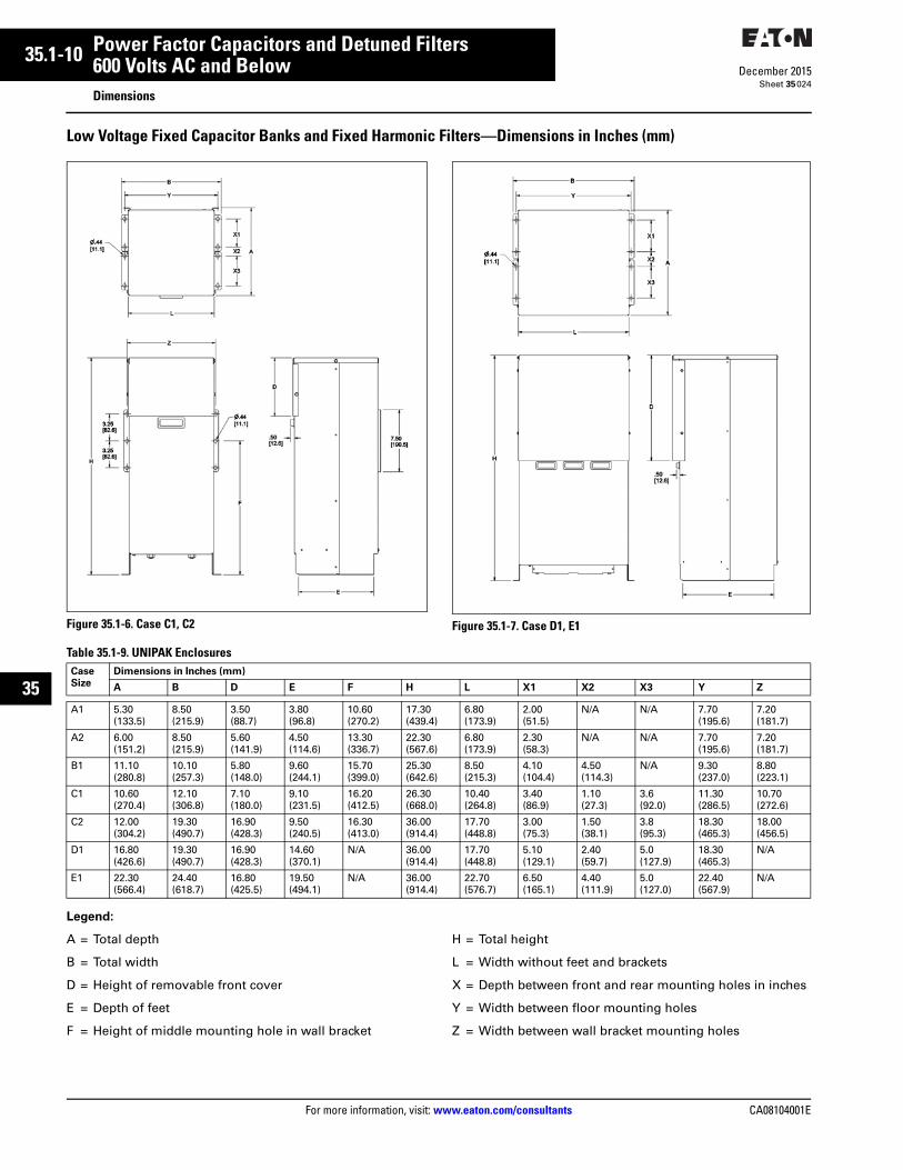
35.1-10
For more information, visit: www.eaton.com/consultants CA08104001E
December 2015
Power Factor Capacitors and Detuned Filters
Sheet 35
22
23
24
25
26
27
28
29
30
31
32
33
34
35
36
37
38
39
40
41
42
43
600 Volts AC and BelowDimensions
024
Low Voltage Fixed Capacitor Banks and Fixed Harmonic Filters—Dimensions in Inches (mm)
Figure 35.1-6. Case C1, C2 Figure 35.1-7. Case D1, E1
Table 35.1-9. UNIPAK Enclosures
Legend:
A = Total depth
B = Total width
D = Height of removable front cover
E = Depth of feet
F = Height of middle mounting hole in wall bracket
H = Total height
L = Width without feet and brackets
X = Depth between front and rear mounting holes in inches
Y = Width between floor mounting holes
Z = Width between wall bracket mounting holes
Case
Size
Dimensions in Inches (mm)
A B D E F H L X1 X2 X3 Y Z
A1 5.30 (133.5)
8.50 (215.9)
3.50 (88.7)
3.80 (96.8)
10.60 (270.2)
17.30 (439.4)
6.80 (173.9)
2.00 (51.5)
N/A N/A 7.70 (195.6)
7.20 (181.7)
A2 6.00 (151.2)
8.50 (215.9)
5.60 (141.9)
4.50 (114.6)
13.30 (336.7)
22.30 (567.6)
6.80 (173.9)
2.30 (58.3)
N/A N/A 7.70 (195.6)
7.20 (181.7)
B1 11.10 (280.8)
10.10(257.3)
5.80 (148.0)
9.60 (244.1)
15.70 (399.0)
25.30 (642.6)
8.50 (215.3)
4.10 (104.4)
4.50(114.3)
N/A 9.30 (237.0)
8.80 (223.1)
C1 10.60 (270.4)
12.10 (306.8)
7.10 (180.0)
9.10(231.5)
16.20 (412.5)
26.30 (668.0)
10.40 (264.8)
3.40 (86.9)
1.10(27.3)
3.6 (92.0)
11.30 (286.5)
10.70 (272.6)
C2 12.00(304.2)
19.30(490.7)
16.90(428.3)
9.50(240.5)
16.30(413.0)
36.00(914.4)
17.70(448.8)
3.00(75.3)
1.50(38.1)
3.8(95.3)
18.30(465.3)
18.00(456.5)
D1 16.80(426.6)
19.30(490.7)
16.90(428.3)
14.60(370.1)
N/A 36.00(914.4)
17.70(448.8)
5.10(129.1)
2.40(59.7)
5.0(127.9)
18.30(465.3)
N/A
E1 22.30(566.4)
24.40(618.7)
16.80(425.5)
19.50(494.1)
N/A 36.00(914.4)
22.70(576.7)
6.50(165.1)
4.40(111.9)
5.0(127.0)
22.40(567.9)
N/A

CA08104001E For more information, visit: www.eaton.com/consultants
35.2-1December 2015
Power Factor Capacitors and Detuned Filters
Sheet 35
22
23
24
25
26
27
28
29
30
31
32
33
34
35
36
37
38
39
40
41
42
43
600 Volts AC and BelowGeneral Description
025
AUTOVAR® 300 Automatic Power Factor Correction Capacitor Systems
AUTOVAR 300
General DescriptionAutomatically switched power factor correction systems for low voltage applications.
■ Wallmount design is ideal for minimum space requirements
■ Programmable to automatically add/subtract capacitor stages to maintain preset target power factor
■ Heavy-duty, three-phase capacitor construction
■ Five-year warranty of cells against manufacturing defects
Application DescriptionAUTOVAR 300 is an ideal capacitor bank to automatically regulate power factor where floor space is limited and expansion of the facility’s electrical load is not expected.
Features
Configuration■ Cabinet: Wallmounting 12 gauge
steel with ANSI 61 gray, NEMA 1 (gasketed)
■ Power line interconnect: Rugged, power distribution block connection. Typical power distribution block can accommodate phase wire sizes from 4 AWG to 500 kcmil; typical ground lug can accommodate wire sizes from 14 AWG to 2/0 AWG. Consult equipment approval drawings for actual lug size
■ Control wiring: UL type MTW/AWM, CSA TEW 105 °C copper wire is standard
■ Fusing: 200,000 A interrupting capacity provided on all three phases of each stage. Blade-type fuses mounted on insulator stand-offs with cleared-fuse indicating lights
■ Cleared-fuse lights: Cleared-fuse neon indicating lights for each phase and stage located on the door
■ Door interlock: Door interlock auto-matically disengages capacitors. Power continues to be provided to the unit until the disconnect is open
■ Exhaust fan: Provides ventilation; dust filtering included
■ Safety: Ground fault interruption provides protection in case of accidental contact with control power and ground
■ Conduit/cable entry: Available in top/side cable entry
■ Thermal sensing: Built-in thermal sensing, alarming, and protection feature allows the unit to operate in optimal temperature while alerting the user of ambient temperature exceeding the nominal operating range. Stages will be automatically switched off if temperature exceeds the maximum specified temperature
■ Temperature range: The operating temperature range is –20 ºC to +46 ºC, and the storage temperature range is –40 ºC to +55 ºC. For optimal equipment life, the temperature should not exceed 35 ºC annual average, and the environment should not exceed Pollution Degree 2 as defined in UL 61010-1
Controller■ Visual indication of incorrect
CT polarity■ Digital display of power factor and
number of energized stages■ Automatic setting of c/k value
(sensitivity based on CT ratio and kvar available)
■ Visual indication of insufficient kvar to reach target power factor
■ Automatic sensing of kvar values per step
■ Optional communications capable controller (RS-485/Modbus®)
■ Standard metering capability:❑ Voltage❑ Current (sensed phase only)❑ Frequency❑ Active power (kW)❑ Reactive power (kvar❑ Apparent power (kVA)❑ Total voltage harmonic distortion
(VTHD)❑ Individual harmonic voltage
distortion (odd orders up to the 19th harmonic)
■ Built-in manual mode allows for testing and manual operation of stages
■ Multiple user-friendly alarm displays. Controller provides easy-to-understand alarms for various conditions, such as:❑ Undervoltage or overvoltage❑ Undercurrent or overcurrent❑ Target power factor not met❑ Harmonic overload❑ Faulty step/stages❑ Overtemperature alarm
Contactor■ Fully rated for capacitor switching■ Integral pre-charge/pre-insertion
module standard. The contactor reduces damaging switching transients, providing safety and durability for the system❑ Lessens the chance of disrupting
sensitive electronic equipment❑ Reduced inrush current extends
the life of the capacitor cells
Options■ Optional main molded-case
circuit breaker■ NEMA 3R weather-resistant enclosure■ Hand-Off-Auto switches■ Remote alarm relay terminal block■ Communications capable controller
Support and Service■ Renewal parts are available through
local Eaton distributors■ Factory trained service personnel
are available through Eaton’s Electrical Services & Systems
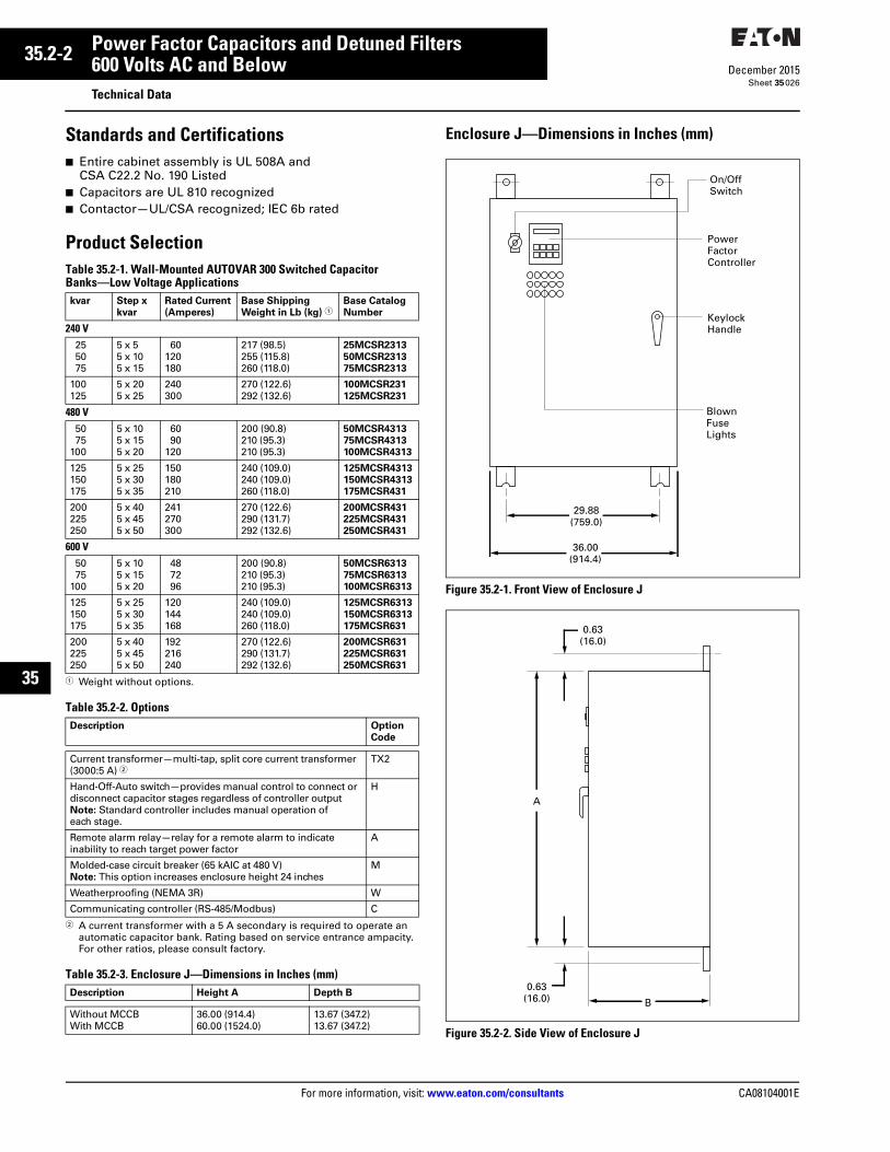
35.2-2
For more information, visit: www.eaton.com/consultants CA08104001E
December 2015
Power Factor Capacitors and Detuned Filters
Sheet 35
22
23
24
25
26
27
28
29
30
31
32
33
34
35
36
37
38
39
40
41
42
43
600 Volts AC and BelowTechnical Data
026
Standards and Certifications■ Entire cabinet assembly is UL 508A and
CSA C22.2 No. 190 Listed■ Capacitors are UL 810 recognized■ Contactor—UL/CSA recognized; IEC 6b rated
Product SelectionTable 35.2-1. Wall-Mounted AUTOVAR 300 Switched Capacitor Banks—Low Voltage Applications
1 Weight without options.
Table 35.2-2. Options
2 A current transformer with a 5 A secondary is required to operate an automatic capacitor bank. Rating based on service entrance ampacity. For other ratios, please consult factory.
Table 35.2-3. Enclosure J—Dimensions in Inches (mm)
Enclosure J—Dimensions in Inches (mm)
Figure 35.2-1. Front View of Enclosure J
Figure 35.2-2. Side View of Enclosure J
kvar Step x
kvar
Rated Current
(Amperes)
Base Shipping
Weight in Lb (kg) 1Base Catalog
Number
240 V255075
5 x 55 x 105 x 15
60120180
217 (98.5)255 (115.8)260 (118.0)
25MCSR2313
50MCSR2313
75MCSR2313
100125
5 x 205 x 25
240300
270 (122.6)292 (132.6)
100MCSR231
125MCSR231
480 V5075
100
5 x 105 x 155 x 20
6090
120
200 (90.8)210 (95.3)210 (95.3)
50MCSR4313
75MCSR4313
100MCSR4313
125150175
5 x 255 x 305 x 35
150180210
240 (109.0)240 (109.0)260 (118.0)
125MCSR4313
150MCSR4313
175MCSR431
200225250
5 x 405 x 455 x 50
241270300
270 (122.6)290 (131.7)292 (132.6)
200MCSR431
225MCSR431
250MCSR431
600 V5075
100
5 x 105 x 155 x 20
487296
200 (90.8)210 (95.3)210 (95.3)
50MCSR6313
75MCSR6313
100MCSR6313
125150175
5 x 255 x 305 x 35
120144168
240 (109.0)240 (109.0)260 (118.0)
125MCSR6313
150MCSR6313
175MCSR631
200225250
5 x 405 x 455 x 50
192216240
270 (122.6)290 (131.7)292 (132.6)
200MCSR631
225MCSR631
250MCSR631
Description Option
Code
Current transformer—multi-tap, split core current transformer (3000:5 A) 2
TX2
Hand-Off-Auto switch—provides manual control to connect or disconnect capacitor stages regardless of controller output Note: Standard controller includes manual operation of each stage.
H
Remote alarm relay—relay for a remote alarm to indicate inability to reach target power factor
A
Molded-case circuit breaker (65 kAIC at 480 V)Note: This option increases enclosure height 24 inches
M
Weatherproofing (NEMA 3R) W
Communicating controller (RS-485/Modbus) C
Description Height A Depth B
Without MCCBWith MCCB
36.00 (914.4)60.00 (1524.0)
13.67 (347.2)13.67 (347.2)
36.00(914.4)
29.88(759.0)
On/OffSwitch
PowerFactorController
KeylockHandle
BlownFuseLights
A
B
0.63(16.0)
0.63(16.0)
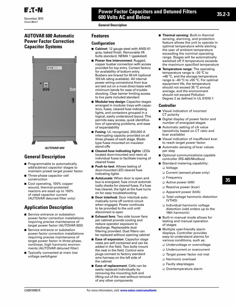
CA08104001E For more information, visit: www.eaton.com/consultants
35.2-3December 2015
Power Factor Capacitors and Detuned Filters
Sheet 35
22
23
24
25
26
27
28
29
30
31
32
33
34
35
36
37
38
39
40
41
42
43
600 Volts AC and BelowGeneral Description
027
AUTOVAR 600 Automatic Power Factor Correction Capacitor Systems
AUTOVAR 600
General Description■ Programmable to automatically
add/subtract capacitor stages to maintain preset target power factor
■ Three-phase capacitor cell construction
■ Cool operating, 100% copper wound, thermal-protected reactors are sized up to 150% of rated capacitor current (AUTOVAR detuned filter only)
Application Description■ Service entrance or substation
power factor correction installations requiring precise maintenance of target power factor (AUTOVAR 600)
■ Service entrance or substation power factor correction installations requiring precise maintenance of target power factor in three-phase, nonlinear, high harmonic environ-ments (AUTOVAR detuned filter)
■ Typically connected at main low voltage switchgear
FeaturesConfiguration■ Cabinet: 12 gauge steel with ANSI 61
gray, baked finish. Removable lift bolts standard, NEMA 1 (gasketed)
■ Power line interconnect: Rugged, copper busbar connection with access provided for top entry. Contact factory for availability of bottom entry. Busbars are braced for 65 kA (optional 100 kA rating available). All internal power wiring connections from bus are laid out on a most direct basis with minimum bends for ease of trouble-shooting. Clear barrier limiting access to live parts included standard
■ Modular tray design: Capacitor stages arranged in modular trays with capac-itors, fuses, cleared-fuse indicating lights, and contactors grouped in a logical, easily understood layout. This permits easy access, quick identifica-tion of operating problems, and ease of expandability
■ Fusing: UL recognized, 200,000 A interrupting capacity provided on all three phases of each stage. Blade-type fuses mounted on insulator stand-offs
■ Cleared-fuse indicating lights: LEDs located door-mounted and neon at individual fuses to facilitate tracing of cleared fuses
■ Push-to-test: Allows testing of door-mounted LED cleared fuse indicating lights
■ AutoLocate: When door is open and bus is energized, fuse circuit automat-ically checks for cleared fuses. If a fuse has cleared, the light at the fuse turns on for easy troubleshooting
■ Door interlock: Door interlock auto-matically turns off control circuit when engaged. Power continues to be provided to the unit until disconnect is open
■ Exhaust fans: Two side louver fans per cabinet provide cooling and reduce operator exposure to discharge. Replaceable dust filtering provided. Dust filters can be replaced without opening cabinet
■ Ease of expansion: Capacitor stage nests are self-contained and can be added in the field. Two bolts mount the nest in the field. Control wire plugs connect to factory standard wire harness on the left side of the cabinet
■ Ease of replacement: Cells can be easily replaced individually by removing the mounting bolt and lifting out of the nest without removal of any other components
■ Thermal sensing: Built-in thermal sensing, alarming, and protection feature allows the unit to operate in optimal temperature while alerting the user of ambient temperature exceeding the nominal operating range. Stages will be automatically switched off if temperature exceeds the maximum specified temperature
■ Temperature range: The operating temperature range is –20 ºC to +46 ºC, and the storage temperature range is –40 ºC to +55 ºC. For optimal equipment life, the temperature should not exceed 35 ºC annual average, and the environment should not exceed Pollution Degree 2 as defined in UL 61010-1
Controller■ Visual indication of incorrect
CT polarity■ Digital display of power factor and
number of energized stages■ Automatic setting of c/k value
(sensitivity based on CT ratio and kvar available)
■ Visual indication of insufficient kvar to reach target power factor
■ Automatic sensing of kvar values per step
■ Optional communications capable controller (RS-485/Modbus)
■ Standard metering capability:❑ Voltage❑ Current (sensed phase only)❑ Frequency❑ Active power (kW)❑ Reactive power (kvar)❑ Apparent power (kVA)❑ Total voltage harmonic distortion
(VTHD)❑ Individual harmonic voltage
distortion (odd orders up to the 19th harmonic)
■ Built-in manual mode allows for testing and manual operation of stages
■ Multiple user-friendly alarm displays. Controller provides easy-to-understand alarms for various conditions, such as:❑ Undervoltage or overvoltage❑ Undercurrent or overcurrent❑ Target power factor not met❑ Harmonic overload❑ Faulty step/stages❑ Overtemperature alarm
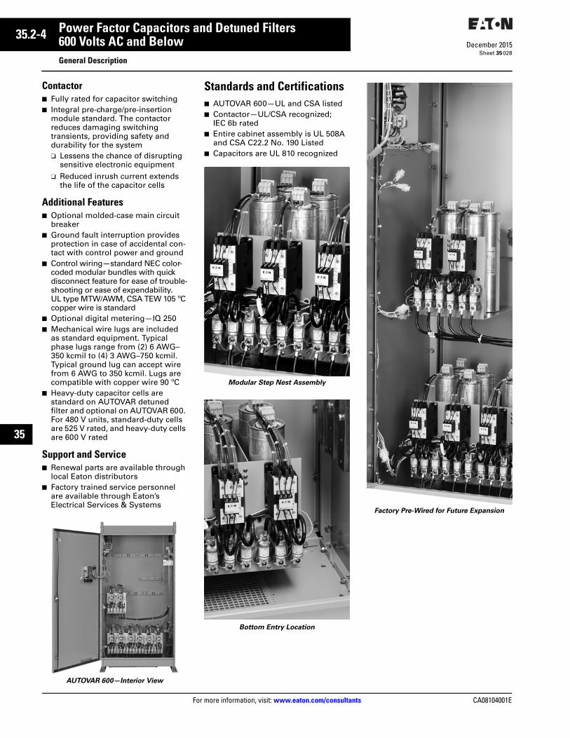
35.2-4
For more information, visit: www.eaton.com/consultants CA08104001E
December 2015
Power Factor Capacitors and Detuned Filters
Sheet 35
22
23
24
25
26
27
28
29
30
31
32
33
34
35
36
37
38
39
40
41
42
43
600 Volts AC and BelowGeneral Description
028
Contactor■ Fully rated for capacitor switching■ Integral pre-charge/pre-insertion
module standard. The contactor reduces damaging switching transients, providing safety and durability for the system❑ Lessens the chance of disrupting
sensitive electronic equipment❑ Reduced inrush current extends
the life of the capacitor cells
Additional Features■ Optional molded-case main circuit
breaker■ Ground fault interruption provides
protection in case of accidental con-tact with control power and ground
■ Control wiring—standard NEC color-coded modular bundles with quick disconnect feature for ease of trouble-shooting or ease of expendability. UL type MTW/AWM, CSA TEW 105 ºC copper wire is standard
■ Optional digital metering—IQ 250■ Mechanical wire lugs are included
as standard equipment. Typical phase lugs range from (2) 6 AWG–350 kcmil to (4) 3 AWG–750 kcmil. Typical ground lug can accept wire from 6 AWG to 350 kcmil. Lugs are compatible with copper wire 90 ºC
■ Heavy-duty capacitor cells are standard on AUTOVAR detuned filter and optional on AUTOVAR 600. For 480 V units, standard-duty cells are 525 V rated, and heavy-duty cells are 600 V rated
Support and Service■ Renewal parts are available through
local Eaton distributors■ Factory trained service personnel
are available through Eaton’s Electrical Services & Systems
AUTOVAR 600—Interior View
Standards and Certifications■ AUTOVAR 600—UL and CSA listed■ Contactor—UL/CSA recognized;
IEC 6b rated■ Entire cabinet assembly is UL 508A
and CSA C22.2 No. 190 Listed■ Capacitors are UL 810 recognized
Modular Step Nest Assembly
Bottom Entry Location
Factory Pre-Wired for Future Expansion

CA08104001E For more information, visit: www.eaton.com/consultants
35.2-5December 2015
Power Factor Capacitors and Detuned Filters
Sheet 35
22
23
24
25
26
27
28
29
30
31
32
33
34
35
36
37
38
39
40
41
42
43
600 Volts AC and BelowTechnical Data
029
Technical Data and SpecificationsTable 35.2-4. AUTOVAR 600 Floor-Mounted Switched Capacitor Bank—Low Voltage Applications
1 Enclosure sizing for units with integrated surge protection or bottom entry can vary and may not be available on all kvar sizes. Contact Eaton’s Technical Resource Center at 1-800-809-2772, choose option #4, then option #2.C/F = Consult factory
kvar Step x kvar Rated Current
(Amperes)
Enclosure Size 1 Base Shipping
Weight in Lb (kg)
Base Catalog
NumberNEMA 1, without Main
Breaker, No Suffix
NEMA 1, with Main
Breaker, M Suffix
240 Vac75
100125
3 x 254 x 255 x 25
180240300
LLL
LLL
644 (292.4)692 (314.2)740 (336.0)
75TPCSR231
100TPCSR231
125TPCSR231
150200250
6 x 258 x 25
10 x 25
361481600
LLL
LLL
788 (357.8)884 (401.3)944 (428.6)
150TPCSR231
200TPCSR231
250TPCSR231
300350400
12 x 257 x 508 x 50
720844965
LKKKK
LKKC/F
1022 (464.0)1616 (734.0)1704 (774.0)
300TPCSR231
350TPCSR231
400TPCSR231
480 Vac100150200
2 x 503 x 504 x 50
120180240
LLL
LLL
588 (266.7)632 (287.0)676 (306.9)
100TPCSR431
150TPCSR431
200TPCSR431
250300350
5 x 506 x 507 x 50
300360420
LLL
LLL
720 (326.9)764 (346.9)808 (366.8)
250TPCSR431
300TPCSR431
350TPCSR431
400450500
8 x 509 x 50
10 x 50
480540600
LLL
LLL
852 (386.8)896 (406.8)944 (428.6)
400TPCSR431
450TPCSR431
500TPCSR431
550600660
11 x 5012 x 5011 x 60
660720792
LLL
LLL
984 (446.7)1022 (464.0)1010 (458.5)
550TPCSR431
600TPCSR431
660TPCSR431
700720800
7 x 10012 x 608 x 100
840864960
LLKK
KKLC/F
1616 (734.0)1050 (476.7)1704 (774.0)
700TPCSR431
720TPCSR431
800TPCSR431
900100011001200
9 x 10010 x 10011 x 10012 x 100
1080120013201440
KKKKKKKK
C/FC/FC/FC/F
1792 (814.0)1888 (857.0)1966 (893.0)2044 (928.0)
900TPCSR431
1000TPCSR431
1100TPCSR431
1200TPCSR431
600 Vac100150200
2 x 503 x 504 x 50
46144192
LLL
LLL
588 (266.7)632 (287.0)676 (306.9)
100TPCSR631
150TPCSR631
200TPCSR631
250300350
5 x 506 x 507 x 50
240288336
LLL
LLL
720 (326.9)764 (346.9)808 (366.8)
250TPCSR631
300TPCSR631
350TPCSR631
400450500
8 x 509 x 50
10 x 50
384432480
LLL
LLL
852 (386.8)896 (406.8)944 (428.6)
400TPCSR631
450TPCSR631
500TPCSR631
550600660
11 x 6012 x 5011 x 60
528576634
LLL
LLL
984 (446.7)1022 (464.0)1010 (458.5)
550TPCSR631
600TPCSR631
660TPCSR631
700720800
7 x 10012 x 608 x 100
672692768
LLKK
KKLKK
1616 (734.0)1050 (476.7)1704 (774.0)
700TPCSR631
720TPCSR631
800TPCSR631
900100011001200
9 x 10010 x 10011 x 10012 x 100
864960
10561152
KKKKKKKK
KKC/FC/FC/F
1792 (814.0)1888 (857.0)1966 (893.0)2044 (928.0)
900TPCSR631
1000TPCSR631
1100TPCSR631
1200TPCSR631

35.2-6
For more information, visit: www.eaton.com/consultants CA08104001E
December 2015
Power Factor Capacitors and Detuned Filters
Sheet 35
22
23
24
25
26
27
28
29
30
31
32
33
34
35
36
37
38
39
40
41
42
43
600 Volts AC and BelowTechnical Data
030
Table 35.2-5. AUTOVAR 600 Floor-Mounted Switched Capacitor Banks Units with Heavy-Duty Cells—Low Voltage Applications
1 Enclosure sizing for units with integrated surge protection or bottom entry can vary and may not be available on all kvar sizes. Contact Eaton’s Technical Resource Center at 1-800-809-2772, choose option #4, then option #2.C/F = Consult factory
kvar Step x kvar Rated
Current
Amperes
Enclosure Size 1 Base
Shipping
Weight in
Lb (kg)
Base Catalog
Number
(NEMA 1,
no options)
NEMA 1, without
Main Breaker,
No Suffix
NEMA 1, with
Main Breaker,
M Suffix
NEMA 3R,
without Main
Breaker, W Suffix
NEMA 1, with
Main Breaker,
MW Suffix
240 Vac75
100125
3 x 254 x 255 x 25
180240300
LLL
LLL
LLL
LLL
659 (298.9)712 (323.0)765 (347.0)
75TPHSR231
100TPHSR231
125TPHSR231
150200250
6 x 258 x 25
10 x 25
361481601
LLL
LLL
LLL
LLL
818 (371.0)924 (419.1)994 (450.9)
150TPHSR231
200TPHSR231
250TPHSR231
300350400
12 x 257 x 508 x 50
720844965
LLKK
LKKC/F
LKKKK
LKKC/F
1082 (490.8)1686 (764.8)1784 (809.2)
300TPHSR231
350TPHSR231
400TPHSR231
480 Vac100150200
2 x 503 x 504 x 50
120180240
LLL
LLL
LLL
LLL
617 (279.9)677 (307.1)736 (333.8)
100TPHSR431
150TPHSR431
200TPHSR431
250300350
5 x 506 x 507 x 50
300360420
LLL
LLL
LLL
LLL
795 (360.6)854 (387.4)913 (414.1)
250TPHSR431
300TPHSR431
350TPHSR431
400450500
8 x 509 x 50
10 x 50
480540600
LLL
LLL
LLL
LLL
972 (440.9)1031 (467.7)1094 (496.2)
400TPHSR431
450TPHSR431
500TPHSR431
550600700
11 x 5012 x 5014 x 50
660720792
LLL
LLKK
LLKK
LLKK
1149 (521.2)1202 (545.2)1826 (828.3)
550TPHSR431
600TPHSR431
700TPHSR431
800900
1000
8 x 1009 x 100
10 x 100
46210831203
KKKKKK
C/FC/FC/F
KKKKKK
C/FC/FC/F
1944 (881.8)2062 (935.3)2198 (997.0)
800TPHSR431
900TPHSR431
1000TPHSR431
11001200
11 x 10012 x 100
13231443
KKKK
C/FC/F
KKKK
C/FC/F
2296 (1041.4)2404 (1090.4)
1100TPHSR431
1200TPHSR431
600 Vac100150200
2 x 503 x 504 x 50
96144192
LLL
LLL
LLL
LLL
617 (279.9)677 (307.1)736 (333.8)
100TPHSR631
150TPHSR631
200TPHSR631
250300350
5 x 506 x 507 x 50
240288336
LLL
LLL
LLL
LLL
795 (360.6)854 (387.4)913 (414.1)
250TPHSR631
300TPHSR631
350TPHSR631
400450500
8 x 509 x 50
10 x 50
384432480
LLL
LLL
LLL
LLL
972 (440.9)1031 (467.7)1094 (496.2)
400TPHSR631
450TPHSR631
500TPHSR631
550600700
11 x 6012 x 507 x 100
529576672
LLL
LLKK
LLKK
LLKK
1149 (521.2)1202 (545.2)1826 (828.3)
550TPHSR631
600TPHSR631
700TPHSR631
800900
1000
8 x 1009 x 100
10 x 100
768864962
KKKKKK
KKKKC/F
KKKKKK
KKKKC/F
1944 (881.8)2062 (935.3)2198 (997.0)
800TPHSR631
900TPHSR631
1000TPHSR631
11001200
11 x 10012 x 100
10581155
KKKK
C/FC/F
KKKK
C/FC/F
2296 (1041.4)2404 (1090.4)
1100TPHSR631
1200TPHSR631
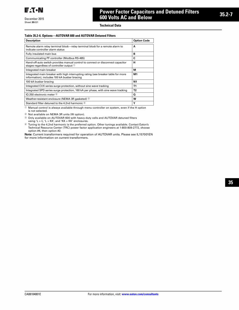
CA08104001E For more information, visit: www.eaton.com/consultants
35.2-7December 2015
Power Factor Capacitors and Detuned Filters
Sheet 35
22
23
24
25
26
27
28
29
30
31
32
33
34
35
36
37
38
39
40
41
42
43
600 Volts AC and BelowTechnical Data
031
Table 35.2-6. Options—AUTOVAR 600 and AUTOVAR Detuned Filters
1 Manual control is always available through menu controller on system, even if the H option is not selected.
2 Not available on NEMA 3R units (W option).3 Only available on AUTOVAR 600 with heavy-duty cells and AUTOVAR detuned filters
using ‘L + L’, ‘L + KK’, and ‘KK + KK’ enclosures.4 Tuning to the 4.2nd harmonic is the preferred option. Other tunings available. Contact Eaton’s
Technical Resource Center (TRC) power factor application engineers at 1-800-809-2772, choose option #4, then option #2.
Note: Current transformers required for operation of AUTOVAR units. Please see IL157001EN for more information on current transformers.
Description Option Code
Remote alarm relay terminal block—relay terminal block for a remote alarm to indicate controller alarm status
A
Fully insulated main bus B
Communicating PF controller (Modbus RS-485) C
Hand-off-auto switch provides manual control to connect or disconnect capacitor stages regardless of controller output 1
H
Integrated main breaker M
Integrated main breaker with high interrupting rating (see breaker table for more information), includes 100 kA busbar bracing
M1
100 kA busbar bracing N1
Integrated CVX series surge protection, without sine wave tracking T1
Integrated SPD series surge protection, 160 kA per phase, with sine wave tracking T2
IQ 250 electronic meter 2 Q
Weather-resistant enclosure (NEMA 3R gasketed) 3 W
Standard filter detuned to the 4.2nd harmonic 4 Y
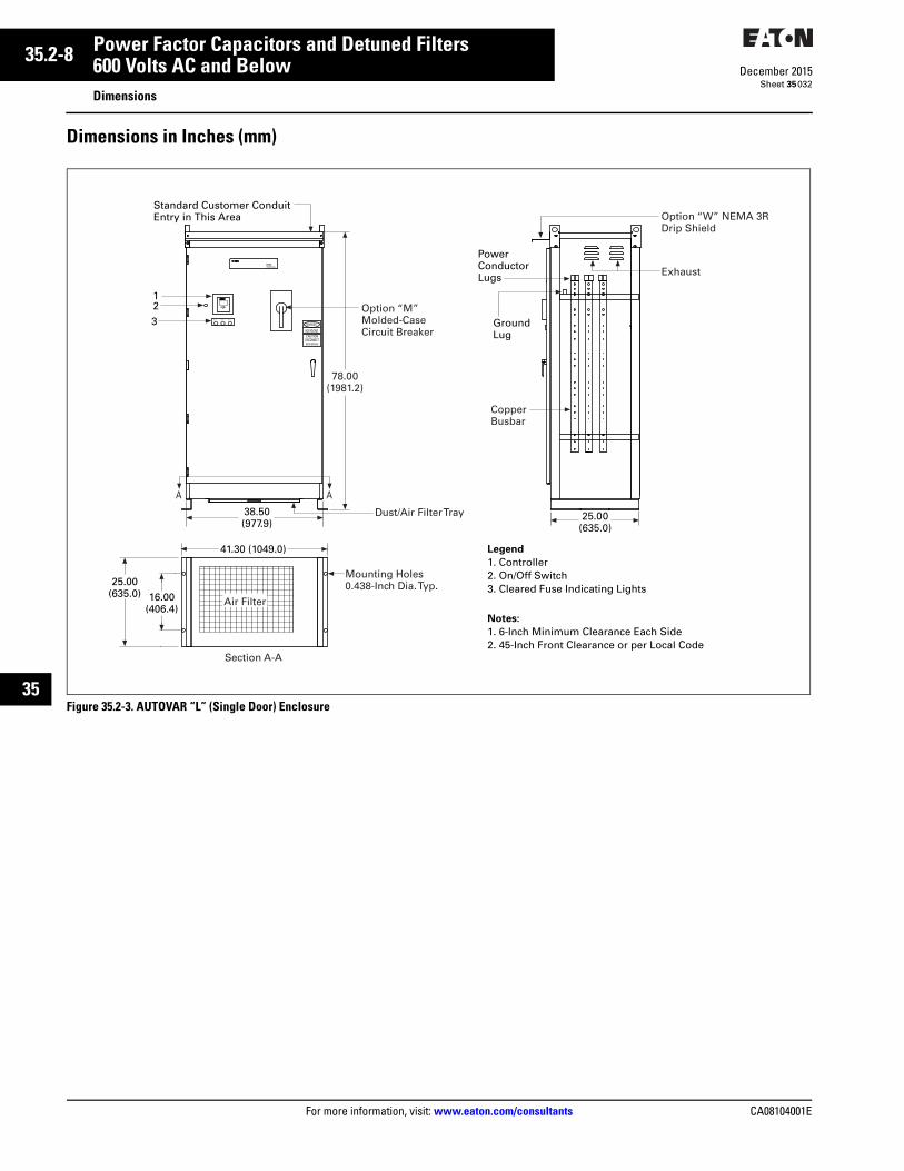
35.2-8
For more information, visit: www.eaton.com/consultants CA08104001E
December 2015
Power Factor Capacitors and Detuned Filters
Sheet 35
22
23
24
25
26
27
28
29
30
31
32
33
34
35
36
37
38
39
40
41
42
43
600 Volts AC and BelowDimensions
032
Dimensions in Inches (mm)
Figure 35.2-3. AUTOVAR “L” (Single Door) Enclosure
PHASE BPHASE A PHASE C
BEFORE SERVICING
HIGH VOLTAGECAUTION
DISCONNECT
DANGER
POWER FACTOR CORRECTION
69B1007G01
BLR-ACXPower Factor Controller
esc
R
Legend
1. Controller2. On/Off Switch3. Cleared Fuse Indicating Lights
Notes:
1. 6-Inch Minimum Clearance Each Side2. 45-Inch Front Clearance or per Local Code
123
16.00(406.4)
25.00(635.0)
Standard Customer Conduit Entry in This Area Option “W” NEMA 3R
Drip Shield
Exhaust
PowerConductorLugs
GroundLug
CopperBusbar
25.00(635.0)
Dust/Air Filter Tray38.50(977.9)
41.30 (1049.0)
Section A-A
Mounting Holes0.438-Inch Dia. Typ.
Air Filter
Option “M”Molded-CaseCircuit Breaker
78.00(1981.2)
A A
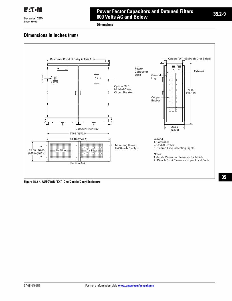
CA08104001E For more information, visit: www.eaton.com/consultants
35.2-9December 2015
Power Factor Capacitors and Detuned Filters
Sheet 35
22
23
24
25
26
27
28
29
30
31
32
33
34
35
36
37
38
39
40
41
42
43
600 Volts AC and BelowDimensions
033
Dimensions in Inches (mm)
Figure 35.2-4. AUTOVAR “KK” (One Double Door) Enclosure
PHASE CPHASE A PHASE B
POWER FACTOR CORRECTION
69B1007G01
BLR-ACXPower Factor Controller
esc
R
12
3
Customer Conduit Entry in This Area
Option “M”Molded-CaseCircuit Breaker
Option “W” NEMA 3R Drip Shield
ExhaustPowerConductorLugs Ground
Lug
CopperBusbar
Dust/Air Filter Tray25.00
(635.0)
78.00(1981.2)
77.64 (1972.0)
A A
80.40 (2042.1)
Section A-A
Mounting Holes0.438-Inch Dia. Typ.
Air Filter Air Filter16.00(406.4)
25.00(635.0)
Legend1. Controller2. On/Off Switch3. Cleared Fuse Indicating Lights
Notes:1. 6-Inch Minimum Clearance Each Side2. 45-Inch Front Clearance or per Local Code
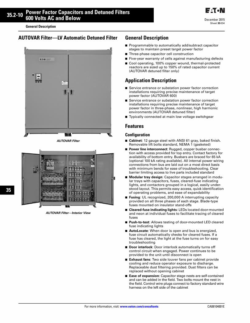
35.2-10
For more information, visit: www.eaton.com/consultants CA08104001E
December 2015
Power Factor Capacitors and Detuned Filters
Sheet 35
22
23
24
25
26
27
28
29
30
31
32
33
34
35
36
37
38
39
40
41
42
43
600 Volts AC and BelowGeneral Description
034
AUTOVAR Filter—LV Automatic Detuned Filter
AUTOVAR Filter
AUTOVAR Filter—Interior View
General Description■ Programmable to automatically add/subtract capacitor
stages to maintain preset target power factor■ Three-phase capacitor cell construction■ Five-year warranty of cells against manufacturing defects■ Cool operating, 100% copper wound, thermal-protected
reactors are sized up to 150% of rated capacitor current (AUTOVAR detuned filter only)
Application Description■ Service entrance or substation power factor correction
installations requiring precise maintenance of target power factor (AUTOVAR 600)
■ Service entrance or substation power factor correction installations requiring precise maintenance of target power factor in three-phase, nonlinear, high harmonic environments (AUTOVAR detuned filter)
■ Typically connected at main low voltage switchgear
Features
Configuration■ Cabinet: 12 gauge steel with ANSI 61 gray, baked finish.
Removable lift bolts standard, NEMA 1 (gasketed)■ Power line interconnect: Rugged, copper busbar connec-
tion with access provided for top entry. Contact factory for availability of bottom entry. Busbars are braced for 65 kA (optional 100 kA rating available). All internal power wiring connections from bus are laid out on a most direct basis with minimum bends for ease of troubleshooting. Clear barrier limiting access to live parts included standard
■ Modular tray design: Capacitor stages arranged in modu-lar trays with capacitors, fuses, cleared-fuse indicating lights, and contactors grouped in a logical, easily under-stood layout. This permits easy access, quick identification of operating problems, and ease of expandability
■ Fusing: UL recognized, 200,000 A interrupting capacity provided on all three phases of each stage. Blade-type fuses mounted on insulator stand-offs
■ Cleared-fuse indicating lights: LEDs located door-mounted and neon at individual fuses to facilitate tracing of cleared fuses
■ Push-to-test: Allows testing of door-mounted LED cleared fuse indicating lights
■ AutoLocate: When door is open and bus is energized, fuse circuit automatically checks for cleared fuses. If a fuse has cleared, the light at the fuse turns on for easy troubleshooting
■ Door interlock: Door interlock automatically turns off control circuit when engaged. Power continues to be provided to the unit until disconnect is open
■ Exhaust fans: Two side louver fans per cabinet provide cooling and reduce operator exposure to discharge. Replaceable dust filtering provided. Dust filters can be replaced without opening cabinet
■ Ease of expansion: Capacitor stage nests are self-contained and can be added in the field. Two bolts mount the nest in the field. Control wire plugs connect to factory standard wire harness on the left side of the cabinet
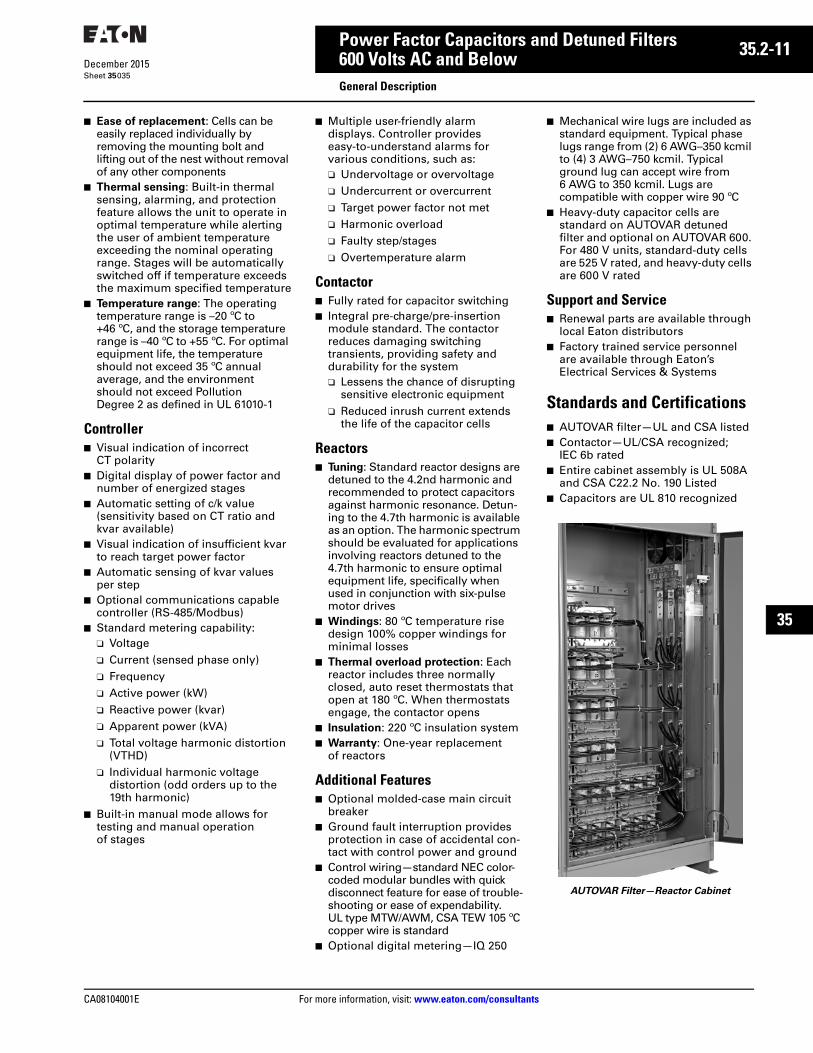
CA08104001E For more information, visit: www.eaton.com/consultants
35.2-11December 2015
Power Factor Capacitors and Detuned Filters
Sheet 35
22
23
24
25
26
27
28
29
30
31
32
33
34
35
36
37
38
39
40
41
42
43
600 Volts AC and BelowGeneral Description
035
■ Ease of replacement: Cells can be easily replaced individually by removing the mounting bolt and lifting out of the nest without removal of any other components
■ Thermal sensing: Built-in thermal sensing, alarming, and protection feature allows the unit to operate in optimal temperature while alerting the user of ambient temperature exceeding the nominal operating range. Stages will be automatically switched off if temperature exceeds the maximum specified temperature
■ Temperature range: The operating temperature range is –20 ºC to +46 ºC, and the storage temperature range is –40 ºC to +55 ºC. For optimal equipment life, the temperature should not exceed 35 ºC annual average, and the environment should not exceed Pollution Degree 2 as defined in UL 61010-1
Controller■ Visual indication of incorrect
CT polarity■ Digital display of power factor and
number of energized stages■ Automatic setting of c/k value
(sensitivity based on CT ratio and kvar available)
■ Visual indication of insufficient kvar to reach target power factor
■ Automatic sensing of kvar values per step
■ Optional communications capable controller (RS-485/Modbus)
■ Standard metering capability:❑ Voltage❑ Current (sensed phase only)❑ Frequency❑ Active power (kW)❑ Reactive power (kvar)❑ Apparent power (kVA)❑ Total voltage harmonic distortion
(VTHD)❑ Individual harmonic voltage
distortion (odd orders up to the 19th harmonic)
■ Built-in manual mode allows for testing and manual operation of stages
■ Multiple user-friendly alarm displays. Controller provides easy-to-understand alarms for various conditions, such as:❑ Undervoltage or overvoltage❑ Undercurrent or overcurrent❑ Target power factor not met❑ Harmonic overload❑ Faulty step/stages❑ Overtemperature alarm
Contactor■ Fully rated for capacitor switching■ Integral pre-charge/pre-insertion
module standard. The contactor reduces damaging switching transients, providing safety and durability for the system❑ Lessens the chance of disrupting
sensitive electronic equipment❑ Reduced inrush current extends
the life of the capacitor cells
Reactors■ Tuning: Standard reactor designs are
detuned to the 4.2nd harmonic and recommended to protect capacitors against harmonic resonance. Detun-ing to the 4.7th harmonic is available as an option. The harmonic spectrum should be evaluated for applications involving reactors detuned to the 4.7th harmonic to ensure optimal equipment life, specifically when used in conjunction with six-pulse motor drives
■ Windings: 80 ºC temperature rise design 100% copper windings for minimal losses
■ Thermal overload protection: Each reactor includes three normally closed, auto reset thermostats that open at 180 ºC. When thermostats engage, the contactor opens
■ Insulation: 220 ºC insulation system■ Warranty: One-year replacement
of reactors
Additional Features■ Optional molded-case main circuit
breaker■ Ground fault interruption provides
protection in case of accidental con-tact with control power and ground
■ Control wiring—standard NEC color-coded modular bundles with quick disconnect feature for ease of trouble-shooting or ease of expendability. UL type MTW/AWM, CSA TEW 105 ºC copper wire is standard
■ Optional digital metering—IQ 250
■ Mechanical wire lugs are included as standard equipment. Typical phase lugs range from (2) 6 AWG–350 kcmil to (4) 3 AWG–750 kcmil. Typical ground lug can accept wire from 6 AWG to 350 kcmil. Lugs are compatible with copper wire 90 ºC
■ Heavy-duty capacitor cells are standard on AUTOVAR detuned filter and optional on AUTOVAR 600. For 480 V units, standard-duty cells are 525 V rated, and heavy-duty cells are 600 V rated
Support and Service■ Renewal parts are available through
local Eaton distributors■ Factory trained service personnel
are available through Eaton’s Electrical Services & Systems
Standards and Certifications■ AUTOVAR filter—UL and CSA listed■ Contactor—UL/CSA recognized;
IEC 6b rated■ Entire cabinet assembly is UL 508A
and CSA C22.2 No. 190 Listed■ Capacitors are UL 810 recognized
AUTOVAR Filter—Reactor Cabinet
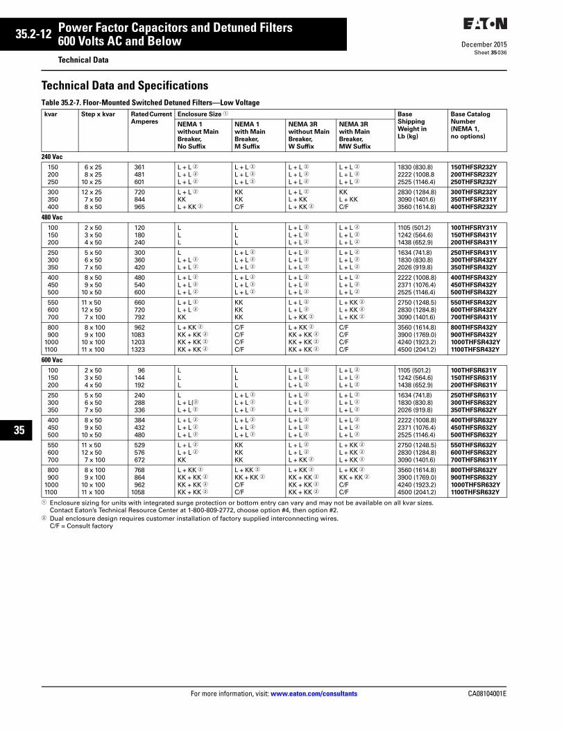
35.2-12
For more information, visit: www.eaton.com/consultants CA08104001E
December 2015
Power Factor Capacitors and Detuned Filters
Sheet 35
22
23
24
25
26
27
28
29
30
31
32
33
34
35
36
37
38
39
40
41
42
43
600 Volts AC and BelowTechnical Data
036
Technical Data and SpecificationsTable 35.2-7. Floor-Mounted Switched Detuned Filters—Low Voltage
1 Enclosure sizing for units with integrated surge protection or bottom entry can vary and may not be available on all kvar sizes. Contact Eaton’s Technical Resource Center at 1-800-809-2772, choose option #4, then option #2.
2 Dual enclosure design requires customer installation of factory supplied interconnecting wires.C/F = Consult factory
kvar Step x kvar Rated Current
Amperes
Enclosure Size 1 Base
Shipping
Weight in
Lb (kg)
Base Catalog
Number
(NEMA 1,
no options)
NEMA 1
without Main
Breaker,
No Suffix
NEMA 1
with Main
Breaker,
M Suffix
NEMA 3R
without Main
Breaker,
W Suffix
NEMA 3R
with Main
Breaker,
MW Suffix
240 Vac150200250
6 x 258 x 25
10 x 25
361481601
L + L 2L + L 2L + L 2
L + L 2L + L 2L + L 2
L + L 2L + L 2L + L 2
L + L 2L + L 2L + L 2
1830 (830.8)2222 (1008.82525 (1146.4)
150THFSR232Y
200THFSR232Y
250THFSR232Y
300350400
12 x 257 x 508 x 50
720844965
L + L 2KKL + KK 2
KKKKC/F
L + L 2L + KKL + KK 2
KKL + KKC/F
2830 (1284.8)3090 (1401.6)3560 (1614.8)
300THFSR232Y
350THFSR231Y
400THFSR232Y
480 Vac100150200
2 x 503 x 504 x 50
120180240
LLL
LLL
L + L 2L + L 2L + L 2
L + L 2L + L 2L + L 2
1105 (501.2)1242 (564.6)1438 (652.9)
100THFSRY31Y
150THFSR431Y
200THFSR431Y
250300350
5 x 506 x 507 x 50
300360420
LL + L 2L + L 2
L + L 2L + L 2L + L 2
L + L 2L + L 2L + L 2
L + L 2L + L 2L + L 2
1634 (741.8)1830 (830.8)2026 (919.8)
250THFSR431Y
300THFSR432Y
350THFSR432Y
400450500
8 x 509 x 50
10 x 50
480540600
L + L 2L + L 2L + L 2
L + L 2L + L 2L + L 2
L + L 2L + L 2L + L 2
L + L 2L + L 2L + L 2
2222 (1008.8)2371 (1076.4)2525 (1146.4)
400THFSR432Y
450THFSR432Y
500THFSR432Y
550600700
11 x 5012 x 507 x 100
660720792
L + L 2L + L 2KK
KKKKKK
L + L 2L + L 2L + KK 2
L + KK 2L + KK 2L + KK 2
2750 (1248.5)2830 (1284.8)3090 (1401.6)
550THFSR432Y
600THFSR432Y
700THFSR431Y
800900
10001100
8 x 1009 x 100
10 x 10011 x 100
962108312031323
L + KK 2KK + KK 2KK + KK 2KK + KK 2
C/FC/FC/FC/F
L + KK 2KK + KK 2KK + KK 2KK + KK 2
C/FC/FC/FC/F
3560 (1614.8)3900 (1769.0)4240 (1923.2)4500 (2041.2)
800THFSR432Y
900THFSR432Y
1000THFSR432Y
1100THFSR432Y
600 Vac100150200
2 x 503 x 504 x 50
96144192
LLL
LLL
L + L 2L + L 2L + L 2
L + L 2L + L 2L + L 2
1105 (501.2)1242 (564.6)1438 (652.9)
100THFSR631Y
150THFSR631Y
200THFSR631Y
250300350
5 x 506 x 507 x 50
240288336
LL + L(2
L + L 2
L + L 2L + L 2L + L 2
L + L 2L + L 2L + L 2
L + L 2L + L 2L + L 2
1634 (741.8)1830 (830.8)2026 (919.8)
250THFSR631Y
300THFSR632Y
350THFSR632Y
400450500
8 x 509 x 50
10 x 50
384432480
L + L 2L + L 2L + L 2
L + L 2L + L 2L + L 2
L + L 2L + L 2L + L 2
L + L 2L + L 2L + L 2
2222 (1008.8)2371 (1076.4)2525 (1146.4)
400THFSR632Y
450THFSR632Y
500THFSR632Y
550600700
11 x 5012 x 507 x 100
529576672
L + L 2L + L 2KK
KKKKKK
L + L 2L + L 2L + KK 2
L + KK 2L + KK 2L + KK 2
2750 (1248.5)2830 (1284.8)3090 (1401.6)
550THFSR632Y
600THFSR632Y
700THFSR631Y
800900
10001100
8 x 1009 x 100
10 x 10011 x 100
768864962
1058
L + KK 2KK + KK 2KK + KK 2KK + KK 2
L + KK 2KK + KK 2C/FC/F
L + KK 2KK + KK 2KK + KK 2KK + KK 2
L + KK 2KK + KK 2C/FC/F
3560 (1614.8)3900 (1769.0)4240 (1923.2)4500 (2041.2)
800THFSR632Y
900THFSR632Y
1000THFSR632Y
1100THFSR632Y
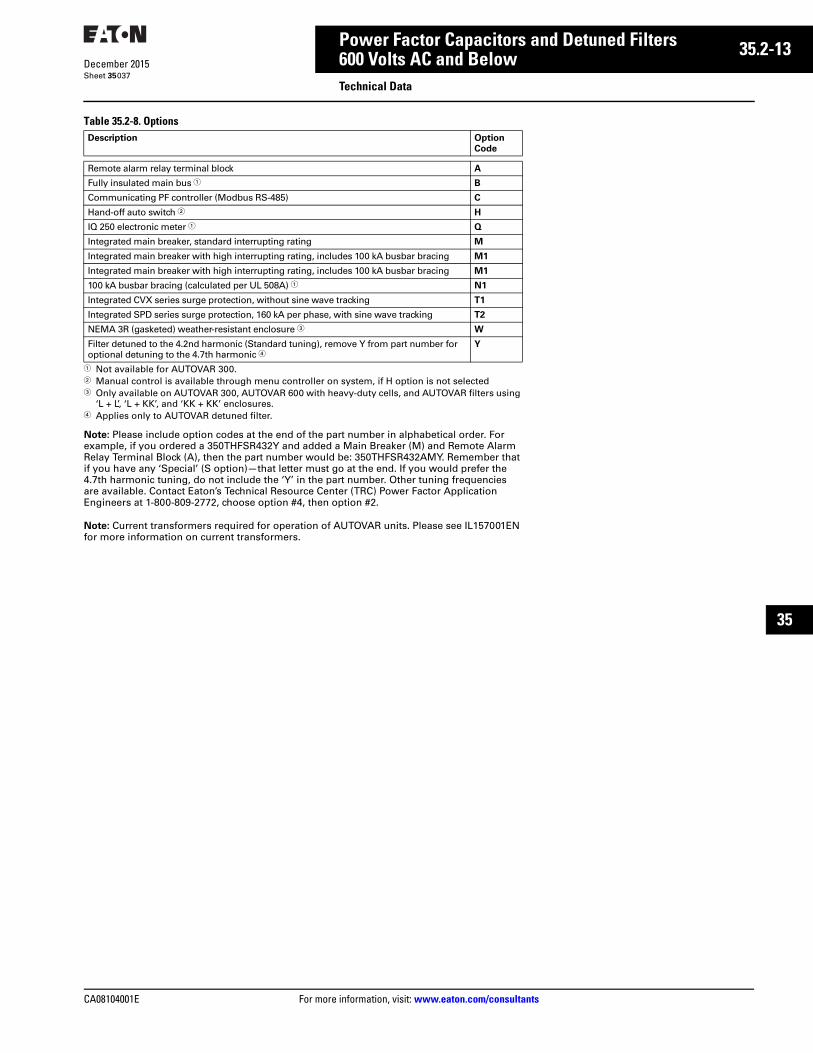
CA08104001E For more information, visit: www.eaton.com/consultants
35.2-13December 2015
Power Factor Capacitors and Detuned Filters
Sheet 35
22
23
24
25
26
27
28
29
30
31
32
33
34
35
36
37
38
39
40
41
42
43
600 Volts AC and BelowTechnical Data
037
Table 35.2-8. Options
1 Not available for AUTOVAR 300.2 Manual control is available through menu controller on system, if H option is not selected3 Only available on AUTOVAR 300, AUTOVAR 600 with heavy-duty cells, and AUTOVAR filters using
‘L + L’, ‘L + KK’, and ‘KK + KK’ enclosures.4 Applies only to AUTOVAR detuned filter.
Note: Please include option codes at the end of the part number in alphabetical order. For example, if you ordered a 350THFSR432Y and added a Main Breaker (M) and Remote Alarm Relay Terminal Block (A), then the part number would be: 350THFSR432AMY. Remember that if you have any ‘Special’ (S option)—that letter must go at the end. If you would prefer the 4.7th harmonic tuning, do not include the ‘Y’ in the part number. Other tuning frequencies are available. Contact Eaton’s Technical Resource Center (TRC) Power Factor Application Engineers at 1-800-809-2772, choose option #4, then option #2.
Note: Current transformers required for operation of AUTOVAR units. Please see IL157001EN for more information on current transformers.
Description Option
Code
Remote alarm relay terminal block A
Fully insulated main bus 1 B
Communicating PF controller (Modbus RS-485) C
Hand-off auto switch 2 H
IQ 250 electronic meter 1 Q
Integrated main breaker, standard interrupting rating M
Integrated main breaker with high interrupting rating, includes 100 kA busbar bracing M1
Integrated main breaker with high interrupting rating, includes 100 kA busbar bracing M1
100 kA busbar bracing (calculated per UL 508A) 1 N1
Integrated CVX series surge protection, without sine wave tracking T1
Integrated SPD series surge protection, 160 kA per phase, with sine wave tracking T2
NEMA 3R (gasketed) weather-resistant enclosure 3 W
Filter detuned to the 4.2nd harmonic (Standard tuning), remove Y from part number for optional detuning to the 4.7th harmonic 4
Y
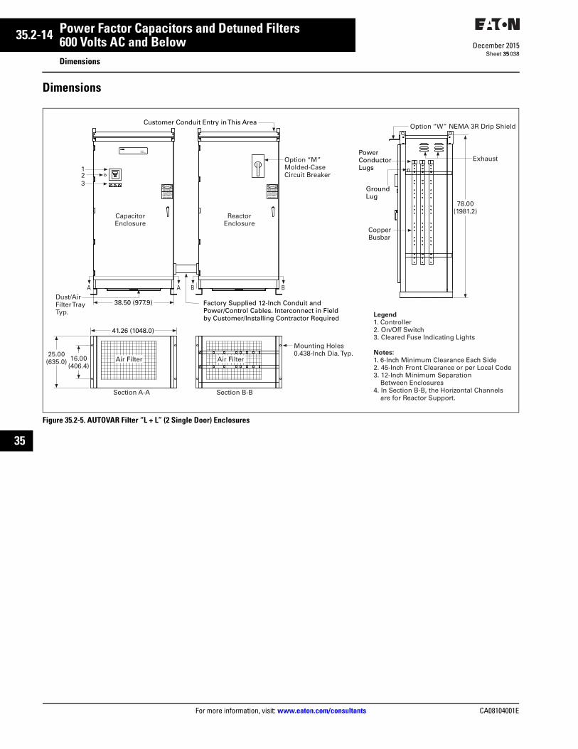
35.2-14
For more information, visit: www.eaton.com/consultants CA08104001E
December 2015
Power Factor Capacitors and Detuned Filters
Sheet 35
22
23
24
25
26
27
28
29
30
31
32
33
34
35
36
37
38
39
40
41
42
43
600 Volts AC and BelowDimensions
038
Dimensions
Figure 35.2-5. AUTOVAR Filter “L + L” (2 Single Door) Enclosures
PHASE A
BLR-CX
PHASE CPHASE B
DANGER
DISCONNECTCAUTIONHIGH VOLTAGE
BEFORE SERVICINGDISCONNECTBEFORE SERVICING
HIGH VOLTAGECAUTION
DANGER
POWER FACTOR CORRECTION
69B1007G01
Customer Conduit Entry in This Area
Option “M”Molded-CaseCircuit Breaker
Option “W” NEMA 3R Drip Shield
ExhaustPowerConductorLugs
GroundLug
CopperBusbar
Dust/AirFilter TrayTyp.
78.00(1981.2)
A A B B
41.26 (1048.0)
Section A-A
Mounting Holes0.438-Inch Dia. Typ.
Air Filter Air Filter
Legend1. Controller2. On/Off Switch3. Cleared Fuse Indicating Lights
Notes:1. 6-Inch Minimum Clearance Each Side2. 45-Inch Front Clearance or per Local Code3. 12-Inch Minimum Separation Between Enclosures4. In Section B-B, the Horizontal Channels are for Reactor Support.
Section B-B
16.00(406.4)
25.00(635.0)
38.50 (977.9)
CapacitorEnclosure
ReactorEnclosure
12
3
Factory Supplied 12-Inch Conduit andPower/Control Cables. Interconnect in Field by Customer/Installing Contractor Required

CA08104001E For more information, visit: www.eaton.com/consultants
35.2-15December 2015
Power Factor Capacitors and Detuned Filters
Sheet 35
22
23
24
25
26
27
28
29
30
31
32
33
34
35
36
37
38
39
40
41
42
43
600 Volts AC and BelowDimensions
039
Figure 35.2-6. “L + KK” Enclosure (AUTOVAR Detuned Filter Only)
Figure 35.2-7. AUTOVAR “KK + KK” Enclosures
PHASE A PHASE CPHASE B
DANGER
DISCONNECTCAUTION
HIGH VOLTAGE
BEFORE SERVICING
BLR-ACXPower Factor Controller
esc
R
1
2
3
Customer Conduit Entry in This AreaOption “W” NEMA 3R Drip Shield
ExhaustPowerConductorLugs Ground
Lug
CopperBusbar
78.00(1981.2)
77.64 (1972.0)
80.40 (2042.1)41.26 (1048.1)
Section A-A Section B-B
Mounting Holes0.438-Inch Dia. Typ.
Air FilterAir Filter Air Filter
Legend1. Controller2. On/Off Switch3. Cleared Fuse Indicating Lights
Notes:1. 6-Inch Minimum Clearance Each Side2. 45-Inch Front Clearance or per Local Code3. 12-Inch Minimum Separation Between Enclosures
16.00(406.4)
25.00(635.0)
Dust/Air Filter Tray Typ.
A A B B
38.50 (977.9)
Factory Supplied 12-Inch Conduit andPower/Control Cables. Interconnect in Field by Customer/Installing Contractor Required
CapacitorEnclosure
ReactorEnclosure
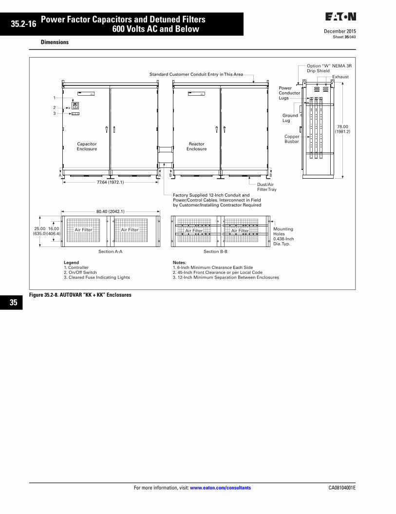
35.2-16
For more information, visit: www.eaton.com/consultants CA08104001E
December 2015
Power Factor Capacitors and Detuned Filters
Sheet 35
22
23
24
25
26
27
28
29
30
31
32
33
34
35
36
37
38
39
40
41
42
43
AUTOVAR “KK + KK” Enclosures600 Volts AC and BelowDimensions
040
Figure 35.2-8. AUTOVAR “KK + KK” Enclosures
PHASE CPHASE A PHASE B
POWER FACTOR CORRECTION
69B1007G01
POWER FACTOR CORRECTION
69B1007G01
BLR-ACXPower Factor Controller
esc
R
1
2
3
Standard Customer Conduit Entry in This Area
Option “W” NEMA 3RDrip Shield
Exhaust
PowerConductorLugs
GroundLug
CopperBusbar
78.00(1981.2)
80.40 (2042.1)
77.64 (1972.1)
Section A-A Section B-B
MountingHoles0.438-InchDia. Typ.
Air FilterAir Filter Air Filter Air Filter
Legend1. Controller2. On/Off Switch3. Cleared Fuse Indicating Lights
Notes:1. 6-Inch Minimum Clearance Each Side2. 45-Inch Front Clearance or per Local Code3. 12-Inch Minimum Separation Between Enclosures
16.00(406.4)
25.00(635.0)
Dust/AirFilter Tray
A A B B
CapacitorEnclosure
ReactorEnclosure
Factory Supplied 12-Inch Conduit andPower/Control Cables. Interconnect in Field by Customer/Installing Contractor Required
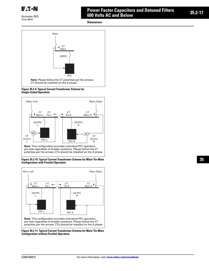
CA08104001E For more information, visit: www.eaton.com/consultants
35.2-17December 2015
Power Factor Capacitors and Detuned Filters
Sheet 35
22
23
24
25
26
27
28
29
30
31
32
33
34
35
36
37
38
39
40
41
42
43
600 Volts AC and BelowDimensions
041
Figure 35.2-9. Typical Current Transformer Scheme for Single-Ended Operation
Figure 35.2-10. Typical Current Transformer Scheme for Main-Tie-Main Configuration with Parallel Operation
Figure 35.2-11. Typical Current Transformer Scheme for Main-Tie-Main Configuration without Parallel Operation
PFC
CBPFC
CTMain
Main
Note: Please follow the CT polarities per the arrows. CT should be installed on the A phase.
CTSumm
R
CTSumm
L
CB PFCR
PFC RPFC L
CB PFCL
CTMain R
CTTie R
CTMain L
CTTie L
Main–Left Main–Right
Note: This configuration provides individual PFC operation per side regardless of breaker positions. Please follow the CT polarities per the arrows. CTs should be installed on the A phase.
CB PFCR
PFC RPFC L
CB PFCL
CTMain R
CTTie R
CTMain L
CTTie L
Main–Left Main–Right
Note: This configuration provides individual PFC operation per side regardless of breaker positions. Please follow the CT polarities per the arrows. CTs should be installed on the A phase.
35.2-18
For more information, visit: www.eaton.com/consultants CA08104001E
December 2015
Power Factor Capacitors and Detuned Filters
Sheet 35
22
23
24
25
26
27
28
29
30
31
32
33
34
35
36
37
38
39
40
41
42
43
042
This page intentionally left blank.
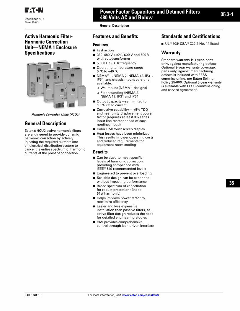
CA08104001E For more information, visit: www.eaton.com/consultants
35.3-1December 2015
Power Factor Capacitors and Detuned Filters
Sheet 35
22
23
24
25
26
27
28
29
30
31
32
33
34
35
36
37
38
39
40
41
42
43
480 Volts AC and BelowGeneral Description
043
Active Harmonic Filter-Harmonic Correction Unit—NEMA 1 Enclosure Specifications
Harmonic Correction Units (HCU2)
General DescriptionEaton’s HCU2 active harmonic filters are engineered to provide dynamic harmonic correction by actively injecting the required currents into an electrical distribution system to cancel the entire spectrum of harmonic currents at the point of connection.
Features and Benefits
Features■ Fast action■ 380–480 V ±10%, 600 V and 690 V
with autotransformer■ 50/60 Hz ±3 Hz frequency■ Operating temperature range
0 °C to +40 °C■ NEMA® 1, NEMA 2, NEMA 12, IP31,
IP54, and chassis mount versions available:❑ Wallmount (NEMA 1 designs)❑ Floor-standing (NEMA 2,
NEMA 12, IP31 and IP54)■ Output capacity—self limited to
100% rated current■ Corrective capability— <5% TDD
and near unity displacement power factor (requires at least 3% series input line reactor ahead of each nonlinear load)
■ Color HMI touchscreen display■ Heat losses have been minimized.
This results in lower operating costs and reduced requirements for equipment room cooling
Benefits■ Can be sized to meet specific
levels of harmonic correction, providing compliance with IEEE® 519 recommended levels
■ Engineered to prevent overloading ■ Scalable design can be expanded
without impacting performance■ Broad spectrum of cancellation
for robust protection (2nd to 51st harmonic)
■ Helps improve power factor to maximize efficiency
■ Easier and less expensive installation than passive filters, as active filter design reduces the need for detailed engineering studies
■ HMI provides comprehensive control through icon-driven interface
Standards and Certifications■ UL® 508/ CSA® C22.2 No. 14 listed
WarrantyStandard warranty is 1 year, parts only, against manufacturing defects. Optional 2-year warranty coverage, parts only, against manufacturing defects is included with EESS commissioning, per Eaton Selling Policy 25-000. Optional 3-year warranty is available with EESS commissioning and service agreement.
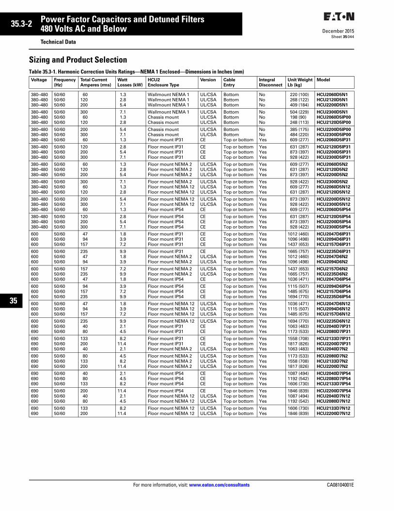
35.3-2
For more information, visit: www.eaton.com/consultants CA08104001E
December 2015
Power Factor Capacitors and Detuned Filters
Sheet 35
22
23
24
25
26
27
28
29
30
31
32
33
34
35
36
37
38
39
40
41
42
43
480 Volts AC and BelowTechnical Data
044
Sizing and Product SelectionTable 35.3-1. Harmonic Correction Units Ratings—NEMA 1 Enclosed—Dimensions in Inches (mm) Voltage Frequency
(Hz)
Total Current
Amperes (rms)
Watt
Losses (kW)
HCU2
Enclosure Type
Version Cable
Entry
Integral
Disconnect
Unit Weight
Lb (kg)
Model
380–480380–480380–480
50/6050/6050/60
60120200
1.32.85.4
Wallmount NEMA 1Wallmount NEMA 1Wallmount NEMA 1
UL/CSAUL/CSAUL/CSA
BottomBottomBottom
NoNoNo
220 (100)268 (122)409 (184)
HCU2060D5N1
HCU2120D5N1
HCU2200D5N1
380–480380–480380–480
50/6050/6050/60
30060
120
7.11.32.8
Wallmount NEMA 1Chassis mountChassis mount
UL/CSAUL/CSAUL/CSA
BottomBottomBottom
NoNoNo
504 (229)198 (90)248 (113)
HCU2300D5N1
HCU2060D5IP00
HCU2120D5IP00
380–480380–480380–480
50/6050/6050/60
20030060
5.47.11.3
Chassis mountChassis mountFloor mount IP31
UL/CSAUL/CSACE
BottomBottomTop or bottom
NoNoYes
385 (175)484 (220)609 (277)
HCU2200D5IP00
HCU2300D5IP00
HCU2060D5IP31
380–480380–480380–480
50/6050/6050/60
120200300
2.85.47.1
Floor mount IP31Floor mount IP31Floor mount IP31
CECECE
Top or bottomTop or bottomTop or bottom
YesYesYes
631 (287)873 (397)928 (422)
HCU2120D5IP31
HCU2200D5IP31
HCU2300D5IP31
380–480380–480380–480
50/6050/6050/60
60120200
1.32.85.4
Floor mount NEMA 2Floor mount NEMA 2Floor mount NEMA 2
UL/CSAUL/CSAUL/CSA
Top or bottomTop or bottomTop or bottom
YesYesYes
609 (277)631 (287)873 (397)
HCU2060D5N2
HCU2120D5N2
HCU2200D5N2
380–480380–480380–480
50/6050/6050/60
30060
120
7.11.32.8
Floor mount NEMA 2Floor mount NEMA 12Floor mount NEMA 12
UL/CSAUL/CSAUL/CSA
Top or bottomTop or bottomTop or bottom
YesYesYes
928 (422)609 (277)631 (287)
HCU2300D5N2
HCU2060D5N12
HCU2120D5N12
380–480380–480380–480
50/6050/6050/60
20030060
5.47.11.3
Floor mount NEMA 12Floor mount NEMA 12Floor mount IP54
UL/CSAUL/CSACE
Top or bottomTop or bottomTop or bottom
YesYesYes
873 (397)928 (422)609 (277)
HCU2200D5N12
HCU2300D5N12
HCU2060D5IP54
380–480380–480380–480
50/6050/6050/60
120200300
2.85.47.1
Floor mount IP54Floor mount IP54Floor mount IP54
CECECE
Top or bottomTop or bottomTop or bottom
YesYesYes
631 (287)873 (397)928 (422)
HCU2120D5IP54
HCU2200D5IP54
HCU2300D5IP54
600600600
50/6050/6050/60
4794
157
1.83.97.2
Floor mount IP31Floor mount IP31Floor mount IP31
CECECE
Top or bottomTop or bottomTop or bottom
YesYesYes
1012 (460)1096 (498)1437 (653)
HCU2047D6IP31
HCU2094D6IP31
HCU2157D6IP31
600600600
50/6050/6050/60
2354794
9.91.83.9
Floor mount IP31Floor mount NEMA 2Floor mount NEMA 2
CEUL/CSAUL/CSA
Top or bottomTop or bottomTop or bottom
YesYesYes
1665 (757)1012 (460)1096 (498)
HCU2235D6IP31
HCU2047D6N2
HCU2094D6N2
600600600
50/6050/6050/60
15723547
7.29.91.8
Floor mount NEMA 2Floor mount NEMA 2Floor mount IP54
UL/CSAUL/CSACE
Top or bottomTop or bottomTop or bottom
YesYesYes
1437 (653)1665 (757)1036 (471)
HCU2157D6N2
HCU2235D6N2
HCU2047D6IP54
600600600
50/6050/6050/60
94157235
3.97.29.9
Floor mount IP54Floor mount IP54Floor mount IP54
CECECE
Top or bottomTop or bottomTop or bottom
YesYesYes
1115 (507)1485 (675)1694 (770)
HCU2094D6IP54
HCU2157D6IP54
HCU2235D6IP54
600600600
50/6050/6050/60
4794
157
1.83.97.2
Floor mount NEMA 12Floor mount NEMA 12Floor mount NEMA 12
UL/CSAUL/CSAUL/CSA
Top or bottomTop or bottomTop or bottom
YesYesYes
1036 (471)1115 (507)1485 (675)
HCU2047D6N12
HCU2094D6N12
HCU2157D6N12
600690690
50/6050/6050/60
2354080
9.92.14.5
Floor mount NEMA 12Floor mount IP31Floor mount IP31
UL/CSACECE
Top or bottomTop or bottomTop or bottom
YesYesYes
1694 (770)1063 (483)1173 (533)
HCU2235D6N12
HCU2040D7IP31
HCU2080D7IP31
690690690
50/6050/6050/60
13320040
8.211.42.1
Floor mount IP31Floor mount IP31Floor mount NEMA 2
CECEUL/CSA
Top or bottomTop or bottomTop or bottom
YesYesYes
1558 (708)1817 (826)1063 (483)
HCU2133D7IP31
HCU2200D7IP31
HCU2040D7N2
690690690
50/6050/6050/60
80133200
4.58.2
11.4
Floor mount NEMA 2Floor mount NEMA 2Floor mount NEMA 2
UL/CSAUL/CSAUL/CSA
Top or bottomTop or bottomTop or bottom
YesYesYes
1173 (533)1558 (708)1817 (826)
HCU2080D7N2
HCU2133D7N2
HCU2200D7N2
690690690
50/6050/6050/60
4080
133
2.14.58.2
Floor mount IP54Floor mount IP54Floor mount IP54
CECECE
Top or bottomTop or bottomTop or bottom
YesYesYes
1087 (494)1192 (542)1606 (730)
HCU2040D7IP54
HCU2080D7IP54
HCU2133D7IP54
690690690
50/6050/6050/60
2004080
11.42.14.5
Floor mount IP54Floor mount NEMA 12Floor mount NEMA 12
CEUL/CSAUL/CSA
Top or bottomTop or bottomTop or bottom
YesYesYes
1846 (839)1087 (494)1192 (542)
HCU2200D7IP54
HCU2040D7N12
HCU2080D7N12
690690
50/6050/60
133200
8.211.4
Floor mount NEMA 12Floor mount NEMA 12
UL/CSAUL/CSA
Top or bottomTop or bottom
YesYes
1606 (730)1846 (839)
HCU2133D7N12
HCU2200D7N12
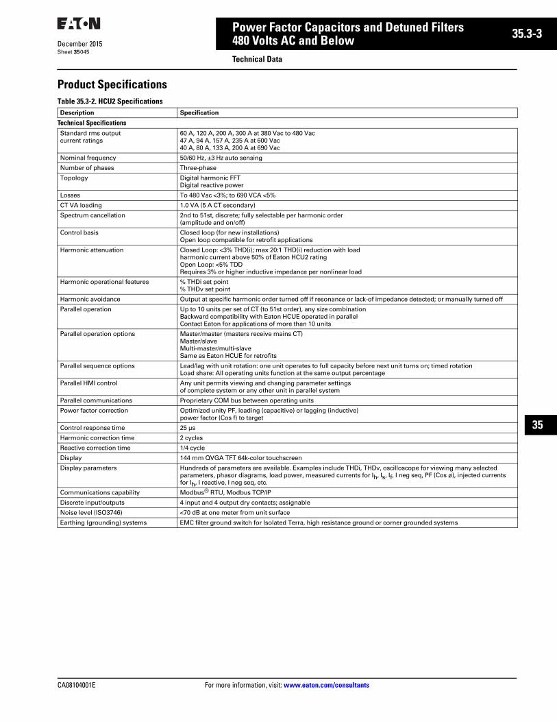
CA08104001E For more information, visit: www.eaton.com/consultants
35.3-3December 2015
Power Factor Capacitors and Detuned Filters
Sheet 35
22
23
24
25
26
27
28
29
30
31
32
33
34
35
36
37
38
39
40
41
42
43
480 Volts AC and BelowTechnical Data
045
Product SpecificationsTable 35.3-2. HCU2 Specifications Description Specification
Technical SpecificationsStandard rms output current ratings
60 A, 120 A, 200 A, 300 A at 380 Vac to 480 Vac47 A, 94 A, 157 A, 235 A at 600 Vac40 A, 80 A, 133 A, 200 A at 690 Vac
Nominal frequency 50/60 Hz, ±3 Hz auto sensing
Number of phases Three-phase
Topology Digital harmonic FFTDigital reactive power
Losses To 480 Vac <3%; to 690 VCA <5%
CT VA loading 1.0 VA (5 A CT secondary)
Spectrum cancellation 2nd to 51st, discrete; fully selectable per harmonic order (amplitude and on/off)
Control basis Closed loop (for new installations) Open loop compatible for retrofit applications
Harmonic attenuation Closed Loop: <3% THD(i); max 20:1 THD(i) reduction with load harmonic current above 50% of Eaton HCU2 ratingOpen Loop: <5% TDDRequires 3% or higher inductive impedance per nonlinear load
Harmonic operational features % THDi set point% THDv set point
Harmonic avoidance Output at specific harmonic order turned off if resonance or lack-of impedance detected; or manually turned off
Parallel operation Up to 10 units per set of CT (to 51st order), any size combinationBackward compatibility with Eaton HCUE operated in parallelContact Eaton for applications of more than 10 units
Parallel operation options Master/master (masters receive mains CT)Master/slaveMulti-master/multi-slaveSame as Eaton HCUE for retrofits
Parallel sequence options Lead/lag with unit rotation: one unit operates to full capacity before next unit turns on; timed rotationLoad share: All operating units function at the same output percentage
Parallel HMI control Any unit permits viewing and changing parameter settings of complete system or any other unit in parallel system
Parallel communications Proprietary COM bus between operating units
Power factor correction Optimized unity PF, leading (capacitive) or lagging (inductive) power factor (Cos f) to target
Control response time 25 µs
Harmonic correction time 2 cycles
Reactive correction time 1/4 cycle
Display 144 mm QVGA TFT 64k-color touchscreen
Display parameters Hundreds of parameters are available. Examples include THDi, THDv, oscilloscope for viewing many selected parameters, phasor diagrams, load power, measured currents for Ih, Is, If, I neg seq, PF (Cos ø), injected currents for Ih, I reactive, I neg seq, etc.
Communications capability Modbus® RTU, Modbus TCP/IP
Discrete input/outputs 4 input and 4 output dry contacts; assignable
Noise level (ISO3746) <70 dB at one meter from unit surface
Earthing (grounding) systems EMC filter ground switch for Isolated Terra, high resistance ground or corner grounded systems

35.3-4
For more information, visit: www.eaton.com/consultants CA08104001E
December 2015
Power Factor Capacitors and Detuned Filters
Sheet 35
22
23
24
25
26
27
28
29
30
31
32
33
34
35
36
37
38
39
40
41
42
43
480 Volts AC and BelowTechnical Data
046
Table 35.3-2. HCU2 Specifications, ContinuedDescription Specification
Environmental ConditionsOperating temperature 0 °C to 40 °C
Relative humidity 0–95%, noncondensing
Seismic rating Complies with IBC and ASCE7
Operating altitude 1000 m, (derate 1%/100 m above), maximum 4800 m
Automatic rollback of output Occurs whenever heatsink temperature sensor exceeds temperature limit
Ambient temperature protection Absolute shutdown if air inlet temperature reaches 51 °C
Preset output limits (rms) Programmable set limit due to altitude or ambient temperature—becomes fixed output limit
Storage (in original shipping container) Temperature: –20 °C to 60 °CRelative humidity: to 95%, noncondensingClean, dry, and protectedNo conductive particles permitted
Contaminant levels—operating (IEC 60721-3-3)
Chemical Class 3C2Mechanical Class 3S2No conductive particles permitted
Reference StandardsDesign CE EMC Certification IEC/EN 60439-1, EN 61000-6-4 Class A, EN 61000-6-2
Protection (enclosure) IP00, IP20, IP31, IP54, UL Type 1, UL Type 2, UL Type 12, UL Type Open
Standards compliance/certification cULus (UL 508, CSA 22.2 No. 14) CE Certified, ABS, Lloyds, other local standards
Installation Wallmount IP00 (UL Type open) and IP20 (NEMA 1) configurations
Free-standing IP31, IP54, NEMA 2 and NEMA 12
Circuit protection NEMA 1 and chassis mount—external means requiredFree-standing enclosures—incoming circuit breaker with mechanical door interlock
AIC rating (input circuit breaker) To 415 Vac—200 kA cULus; 125 kA IECTo 480 Vac—200 kA cULus; 75 kA IECTo 600 Vac—100 kA cULus; 100 kA IECTo 690 Vac—No cULus; 100 kA IEC
Cable entry Wallmount and chassis mount—bottom onlyFree-standing—top and bottom entry through gland plates
PCBA protection Conformal coating on all PCBsPollution Degree 2
Cooling configuration Separate air plenums for heat sink section and control section:Heatsink (high heat plenum) input from bottom and exhaust out topAll components in high heat plenum rated IP54 or better M no filtering requiredControl section air supply must be clean and dry (filtering may be required)No conductive particles permitted
Air supply 60 A to 480 Vac: 570 m3/h, 335 cfm; to 690 Vac: 920 m3/h, 541 cfm120 A to 480 Vac: 1030 m3/h, 606 cfm; to 690 Vac 1380 m3/h, 812 cfm200 A to 480 Vac: 2100 m3/h, 1236 cfm; to 690 Vac: 2850 m3/h, 1677 cfm300 A to 480 Vac: 2100 m3/h, 1236 cfm; to 690 Vac: 2850 m3/h, 1677 cfm
Service ProvisionsHMI Plain language output (without cryptic codes)
USB port for upload of new software and download of operational records
Service port USB port: commission, program, or diagnostics via a laptop computer when power is on or off; laptop provides power to control board when no unit power is present
Commissioning On-board step-by-step process; CT automatic sizing, phase rotation, and polarity; external transformer ratio and phase shift; heat test, and more
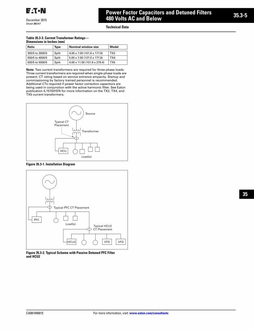
CA08104001E For more information, visit: www.eaton.com/consultants
35.3-5December 2015
Power Factor Capacitors and Detuned Filters
Sheet 35
22
23
24
25
26
27
28
29
30
31
32
33
34
35
36
37
38
39
40
41
42
43
480 Volts AC and BelowTechnical Data
047
Table 35.3-3. Current Transformer Ratings—Dimensions in Inches (mm)
Note: Two current transformers are required for three-phase loads. Three current transformers are required when single-phase loads are present. CT rating based on service entrance ampacity. Startup and commissioning by factory trained personnel is recommended. Additional CTs required if power factor correction capacitors are being used in conjunction with the active harmonic filter. See Eaton publication IL157001EN for more information on the TX2, TX4, and TX5 current transformers.
Figure 35.3-1. Installation Diagram
Figure 35.3-2. Typical Scheme with Passive Detuned PFC Filter and HCU2
Ratio Type Nominal window size Model
300/5 to 3000/5 Split 4.00 x 7.00 (101.6 x 177.8) TX2
500/5 to 4000/5 Split 5.00 x 7.00 (127.0 x 177.8) TX4
500/5 to 5000/5 Split 4.00 x 11.00 (101.6 x 279.4) TX5
Source
Transformer
Typical CTPlacement
HCU
Load(s)
Typical PFC CT Placement
PFC
Load(s)
HCU2 VFD VFD
Typical HCU2CT Placement
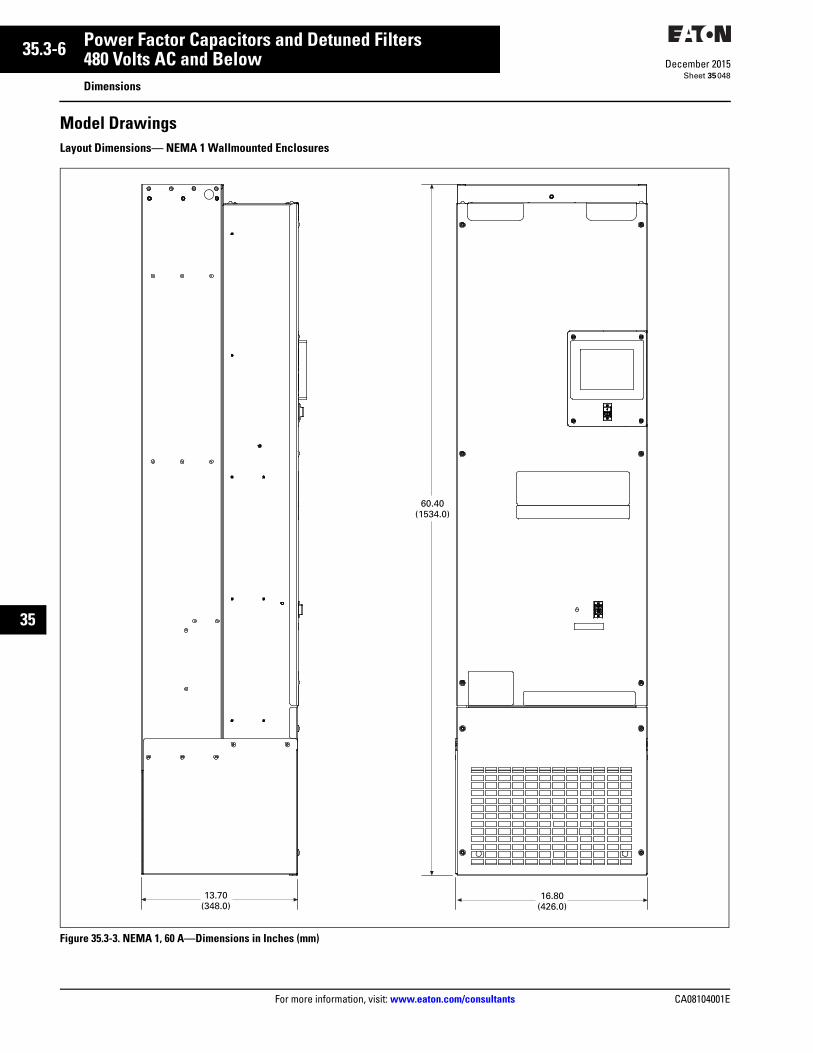
35.3-6
For more information, visit: www.eaton.com/consultants CA08104001E
December 2015
Power Factor Capacitors and Detuned Filters
Sheet 35
22
23
24
25
26
27
28
29
30
31
32
33
34
35
36
37
38
39
40
41
42
43
480 Volts AC and BelowDimensions
048
Model DrawingsLayout Dimensions— NEMA 1 Wallmounted Enclosures
Figure 35.3-3. NEMA 1, 60 A—Dimensions in Inches (mm)
60.40(1534.0)
13.70(348.0)
16.80(426.0)
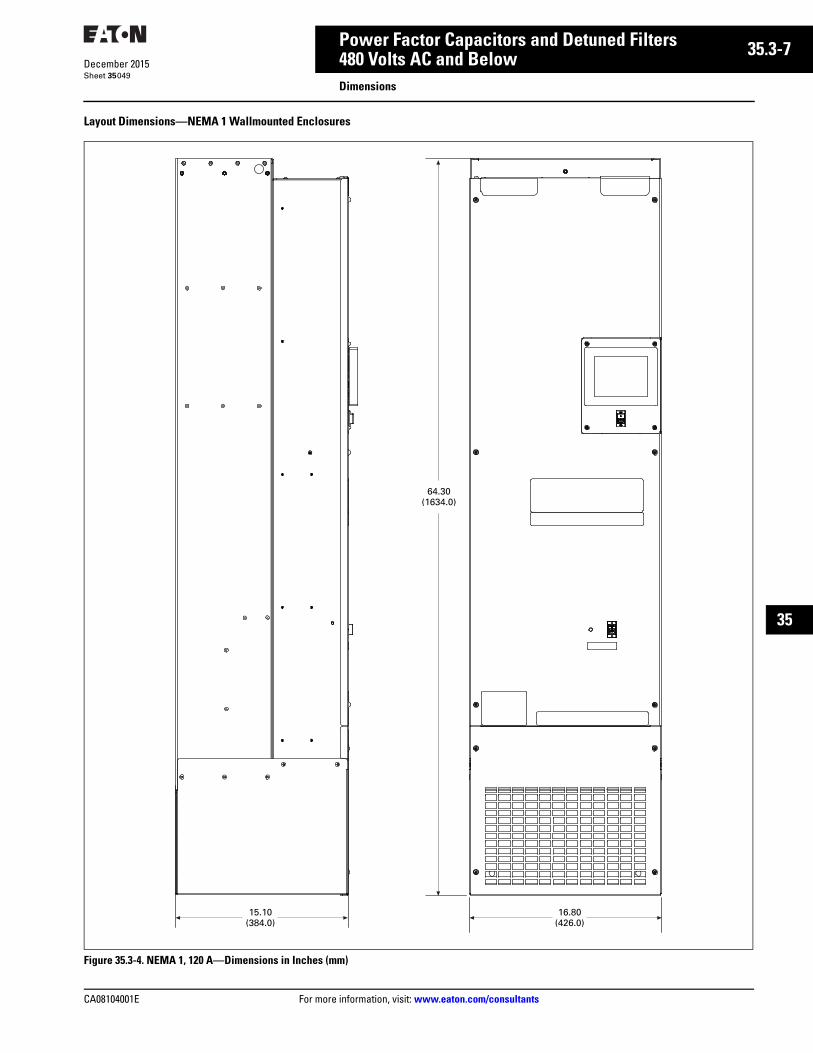
CA08104001E For more information, visit: www.eaton.com/consultants
35.3-7December 2015
Power Factor Capacitors and Detuned Filters
Sheet 35
22
23
24
25
26
27
28
29
30
31
32
33
34
35
36
37
38
39
40
41
42
43
480 Volts AC and BelowDimensions
049
Layout Dimensions—NEMA 1 Wallmounted Enclosures
Figure 35.3-4. NEMA 1, 120 A—Dimensions in Inches (mm)
64.30(1634.0)
15.10(384.0)
16.80(426.0)

35.3-8
For more information, visit: www.eaton.com/consultants CA08104001E
December 2015
Power Factor Capacitors and Detuned Filters
Sheet 35
22
23
24
25
26
27
28
29
30
31
32
33
34
35
36
37
38
39
40
41
42
43
480 Volts AC and BelowDimensions
050
Layout Dimensions—NEMA 1 Wallmounted Enclosures
Figure 35.3-5. NEMA 1, 200 A—Dimensions in Inches (mm)
62.90(1598.0)
17.20(437.0)
22.90(581.0)

CA08104001E For more information, visit: www.eaton.com/consultants
35.3-9December 2015
Power Factor Capacitors and Detuned Filters
Sheet 35
22
23
24
25
26
27
28
29
30
31
32
33
34
35
36
37
38
39
40
41
42
43
480 Volts AC and BelowDimensions
051
Layout Dimensions—NEMA 1 Wallmounted Enclosures
Figure 35.3-6. NEMA 1, 300 A—Dimensions in Inches (mm)
72.20(1835.0)
17.20(438.0)
22.90(581.0)
Lift Here
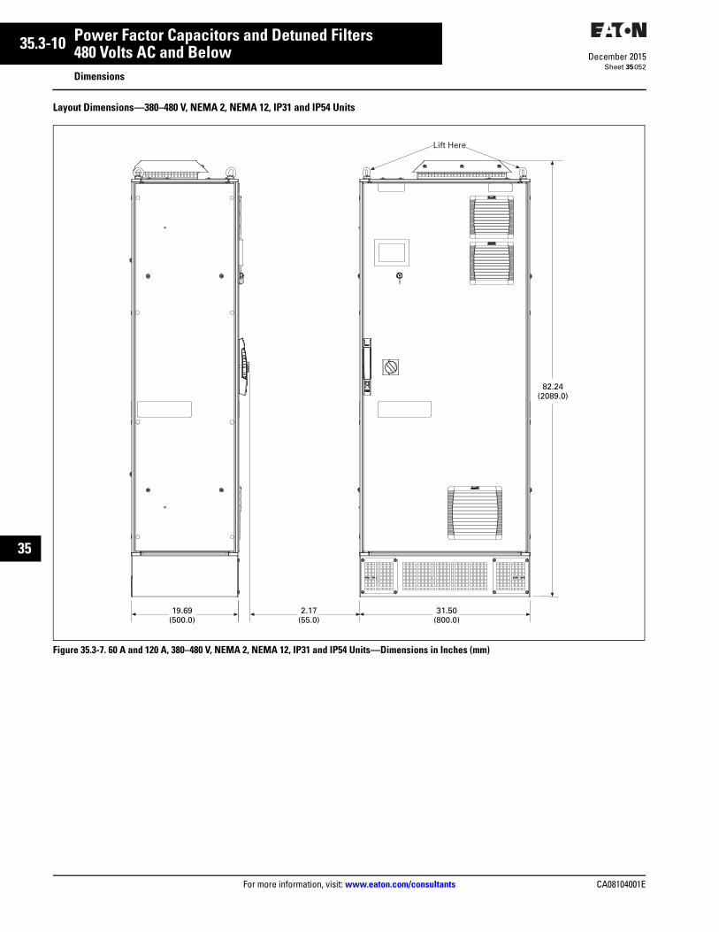
35.3-10
For more information, visit: www.eaton.com/consultants CA08104001E
December 2015
Power Factor Capacitors and Detuned Filters
Sheet 35
22
23
24
25
26
27
28
29
30
31
32
33
34
35
36
37
38
39
40
41
42
43
480 Volts AC and BelowDimensions
052
Layout Dimensions—380–480 V, NEMA 2, NEMA 12, IP31 and IP54 Units
Figure 35.3-7. 60 A and 120 A, 380–480 V, NEMA 2, NEMA 12, IP31 and IP54 Units—Dimensions in Inches (mm)
82.24(2089.0)
19.69(500.0)
31.50(800.0)
2.17(55.0)
Lift Here

CA08104001E For more information, visit: www.eaton.com/consultants
35.3-11December 2015
Power Factor Capacitors and Detuned Filters
Sheet 35
22
23
24
25
26
27
28
29
30
31
32
33
34
35
36
37
38
39
40
41
42
43
480 Volts AC and BelowDimensions
053
Layout Dimensions—380–480 V, NEMA 2, NEMA 12, IP31 and IP54 Units
Figure 35.3-8. 200 A and 300 A, 380–480 V, NEMA 2, NEMA 12, IP31 and IP54 Units—Dimensions in Inches (mm)
82.32(2091.0)
23.62(600.0)
Lift Here
35.43(900.0)
2.09(53.0)

35.3-12
For more information, visit: www.eaton.com/consultants CA08104001E
December 2015
Power Factor Capacitors and Detuned Filters
Sheet 35
22
23
24
25
26
27
28
29
30
31
32
33
34
35
36
37
38
39
40
41
42
43
054
This page intentionally left blank.
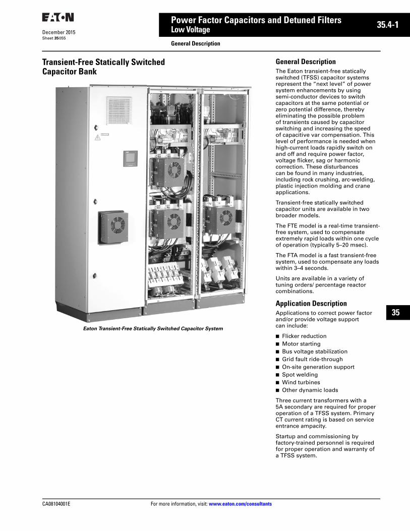
CA08104001E For more information, visit: www.eaton.com/consultants
35.4-1December 2015
Power Factor Capacitors and Detuned Filters
Sheet 35
22
23
24
25
26
27
28
29
30
31
32
33
34
35
36
37
38
39
40
41
42
43
Low Voltage
General Description055
Transient-Free Statically SwitchedCapacitor Bank
Eaton Transient-Free Statically Switched Capacitor System
General DescriptionThe Eaton transient-free statically switched (TFSS) capacitor systems represent the “next level” of power system enhancements by using semi-conductor devices to switch capacitors at the same potential or zero potential difference, thereby eliminating the possible problem of transients caused by capacitor switching and increasing the speed of capacitive var compensation. This level of performance is needed when high-current loads rapidly switch on and off and require power factor, voltage flicker, sag or harmonic correction. These disturbances can be found in many industries, including rock crushing, arc-welding, plastic injection molding and crane applications.
Transient-free statically switched capacitor units are available in two broader models.
The FTE model is a real-time transient-free system, used to compensate extremely rapid loads within one cycle of operation (typically 5–20 msec).
The FTA model is a fast transient-free system, used to compensate any loads within 3–4 seconds.
Units are available in a variety of tuning orders/ percentage reactor combinations.
Application DescriptionApplications to correct power factor and/or provide voltage support can include:
■ Flicker reduction■ Motor starting ■ Bus voltage stabilization ■ Grid fault ride-through■ On-site generation support■ Spot welding■ Wind turbines■ Other dynamic loads
Three current transformers with a 5A secondary are required for proper operation of a TFSS system. Primary CT current rating is based on service entrance ampacity.
Startup and commissioning by factory-trained personnel is required for proper operation and warranty of a TFSS system.

35.4-2
For more information, visit: www.eaton.com/consultants CA08104001E
December 2015
Power Factor Capacitors and Detuned Filters
Sheet 35
22
23
24
25
26
27
28
29
30
31
32
33
34
35
36
37
38
39
40
41
42
43
056
This page intentionally left blank.
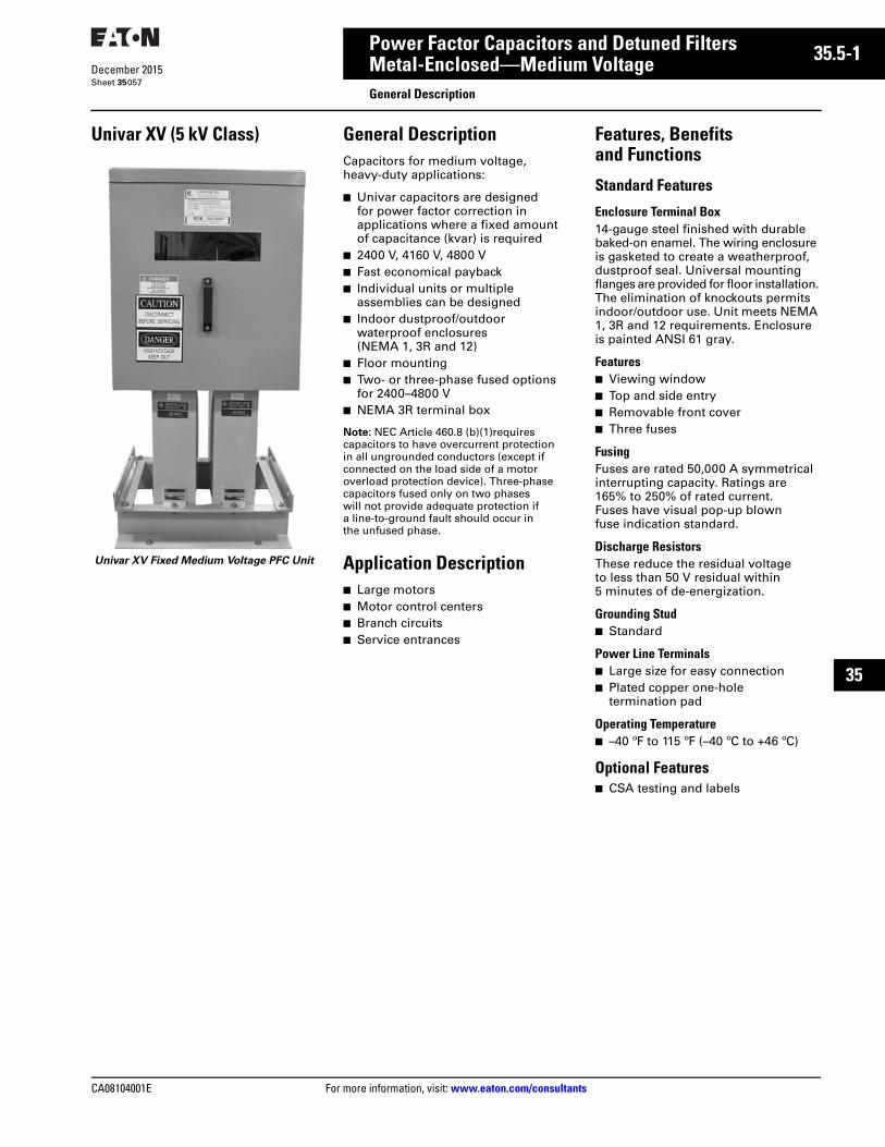
CA08104001E For more information, visit: www.eaton.com/consultants
35.5-1December 2015
Power Factor Capacitors and Detuned Filters
Sheet 35
22
23
24
25
26
27
28
29
30
31
32
33
34
35
36
37
38
39
40
41
42
43
Metal-Enclosed—Medium VoltageGeneral Description
057
Univar XV (5 kV Class)
Univar XV Fixed Medium Voltage PFC Unit
General DescriptionCapacitors for medium voltage, heavy-duty applications:
■ Univar capacitors are designed for power factor correction in applications where a fixed amount of capacitance (kvar) is required
■ 2400 V, 4160 V, 4800 V■ Fast economical payback■ Individual units or multiple
assemblies can be designed■ Indoor dustproof/outdoor
waterproof enclosures (NEMA 1, 3R and 12)
■ Floor mounting■ Two- or three-phase fused options
for 2400–4800 V■ NEMA 3R terminal box
Note: NEC Article 460.8 (b)(1)requires capacitors to have overcurrent protection in all ungrounded conductors (except if connected on the load side of a motor overload protection device). Three-phase capacitors fused only on two phases will not provide adequate protection if a line-to-ground fault should occur in the unfused phase.
Application Description■ Large motors■ Motor control centers■ Branch circuits■ Service entrances
Features, Benefits and Functions
Standard Features
Enclosure Terminal Box14-gauge steel finished with durable baked-on enamel. The wiring enclosure is gasketed to create a weatherproof, dustproof seal. Universal mounting flanges are provided for floor installation. The elimination of knockouts permits indoor/outdoor use. Unit meets NEMA 1, 3R and 12 requirements. Enclosure is painted ANSI 61 gray.
Features■ Viewing window■ Top and side entry■ Removable front cover■ Three fuses
FusingFuses are rated 50,000 A symmetrical interrupting capacity. Ratings are 165% to 250% of rated current. Fuses have visual pop-up blown fuse indication standard.
Discharge ResistorsThese reduce the residual voltage to less than 50 V residual within 5 minutes of de-energization.
Grounding Stud■ Standard
Power Line Terminals■ Large size for easy connection■ Plated copper one-hole
termination pad
Operating Temperature■ –40 ºF to 115 ºF (–40 ºC to +46 ºC)
Optional Features■ CSA testing and labels

35.5-2
For more information, visit: www.eaton.com/consultants CA08104001E
December 2015
Power Factor Capacitors and Detuned Filters
Sheet 35
22
23
24
25
26
27
28
29
30
31
32
33
34
35
36
37
38
39
40
41
42
43
Metal-Enclosed—Medium VoltageTechnical Data
058
Technical Data and SpecificationsTable 35.5-1. UNIVAR Three-Phase Ratings
Table 35.5-2. Three-Phase Fused
Note: Add suffix “C” for CSA label.
Volts Hertz kvar
240041604800
606060
25–82525–90025–900
kvar 2400 V 4160 V 4800 V Dimension (A)
Inches (mm)
Approx. Weight
Lb (kg)
Figure
Number
255075
25243MVF3
50243MVF3
75243MVF3
25413MVF3
50413MVF3
75413MVF3
25483MVF3
50483MVF3
75483MVF3
34.44 (875.0)34.44 (875.0)34.44 (875.0)
72 (32)72 (32)72 (32)
Figure 35.5-1
Figure 35.5-1
Figure 35.5-1
100125150
100243MVF3
125243MVF3
150243MVF3
100413MVF3
125413MVF3
150413MVF3
100483MVF3
125483MVF3
150483MVF3
36.19 (919.0)36.19 (919.0)36.19 (919.0)
77 (34)85 (38)90 (40)
Figure 35.5-1
Figure 35.5-1
Figure 35.5-1
175200225
175243MVF3
200243MVF3
225243MVF3
175413MVF3
200413MVF3
225413MVF3
175483MVF3
200483MVF3
225483MVF3
36.19 (919.0)36.19 (919.0)41.94 (1065.0)
95 (42)101 (45)111 (49)
Figure 35.5-1
Figure 35.5-1
Figure 35.5-1
250275300
250243MVF3
275243MVF3
—
250413MVF3
275413MVF3
300413MVF3
250483MVF3
275483MVF3
300483MVF3
41.94 (1065.0)41.94 (1065.0)41.94 (1065.0)
111 (49)123 (55)123 (55)
Figure 35.5-1
Figure 35.5-1
Figure 35.5-1
300325350
300243MVF3
325243MVF3
350243MVF3
—
325413MVF3
350413MVF3
—
325483MVF3
350483MVF3
36.19 (919.0)36.19 (919.0)36.19 (919.0)
176 (78)181 (80)186 (83)
Figure 35.5-2
Figure 35.5-2
Figure 35.5-2
375400425
375243MVF3
400243MVF3
425243MVF3
375413MVF3
400413MVF3
425413MVF3
375483MVF3
400483MVF3
425483MVF3
36.19 (919.0)36.19 (919.0)41.94 (1065.0)
192 (85)198 (88)210 (93)
Figure 35.5-2
Figure 35.5-2
Figure 35.5-2
450475500
450243MVF3
475243MVF3500243MVF3
450413MVF3
475413MVF3
500413MVF3
450483MVF3
475483MVF3
500483MVF3
41.94 (1065.0)41.94 (1065.0)41.94 (1065.0)
218 (97)218 (97)218 (97)
Figure 35.5-2
Figure 35.5-2
Figure 35.5-2
525550575
525243MVF3
550243MVF3
—
525413MVF3
550413MVF3
575413MVF3
525483MVF3
550483MVF3
575483MVF3
41.94 (1065.0)41.94 (1065.0)41.94 (1065.0)
230 (103)242 (108)242 (108)
Figure 35.5-2
Figure 35.5-2
Figure 35.5-2
575600600
575243MVF3
—
600243MVF3
—
600413MVF3
—
—
600483MVF3
—
36.19 (919.0)41.94 (1065.0)36.19 (919.0)
265 (118)242 (108)271 (121)
Figure 35.5-3
Figure 35.5-2
Figure 35.5-3
625650675
625243MVF3
650243MVF3
675243MVF3
625413MVF3
650413MVF3
675413MVF3
625483MVF3
650483MVF3
675483MVF3
41.94 (1065.0)41.94 (1065.0)41.94 (1065.0)
285 (127)293 (131)301 (134)
Figure 35.5-3
Figure 35.5-3
Figure 35.5-3
700725750
700243MVF3
725243MVF3
750243MVF3
700413MVF3
725413MVF3
750413MVF3
700483MVF3
725483MVF3
750483MVF3
41.94 (1065.0)41.94 (1065.0)41.94 (1065.0)
301 (134)301 (134)301 (134)
Figure 35.5-3
Figure 35.5-3
Figure 35.5-3
775800825
775243MVF3
800243MVF3
825243MVF3
775413MVF3
800413MVF3
825413MVF3
775483MVF3
800483MVF3
825483MVF3
41.94 (1065.0)41.94 (1065.0)41.94 (1065.0)
313 (140)325 (145)337 (151)
Figure 35.5-3
Figure 35.5-3
Figure 35.5-3
850875900
—
—
—
850413MVF3
875413MVF3
900413MVF3
850483MVF3
875483MVF3
900483MVF3
41.94 (1065.0)41.94 (1065.0)41.94 (1065.0)
337 (151)337 (151)337 (151)
Figure 35.5-3
Figure 35.5-3
Figure 35.5-3

CA08104001E For more information, visit: www.eaton.com/consultants
35.5-3December 2015
Power Factor Capacitors and Detuned Filters
Sheet 35
22
23
24
25
26
27
28
29
30
31
32
33
34
35
36
37
38
39
40
41
42
43
Metal-Enclosed—Medium VoltageDimensions
059
Dimensions
Figure 35.5-1. UNIVAR XV 5 kV Class, 25–300 kvar
Figure 35.5-2. UNIVAR XV 5 kV Class, 300–600 kvar
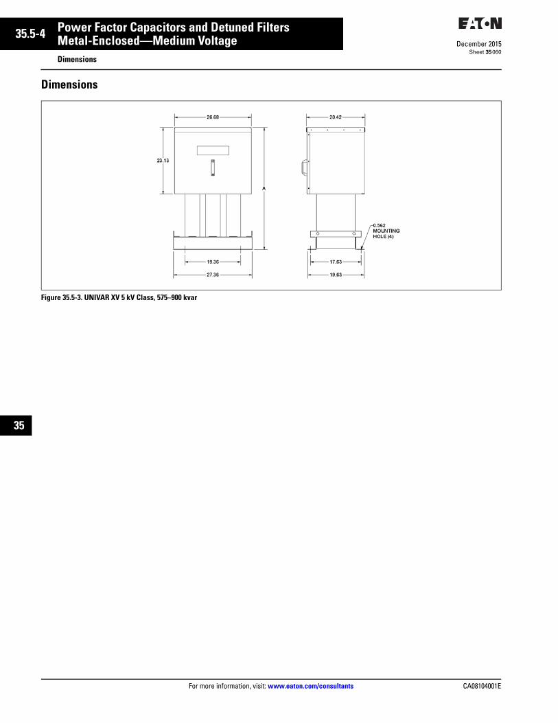
35.5-4
For more information, visit: www.eaton.com/consultants CA08104001E
December 2015
Power Factor Capacitors and Detuned Filters
Sheet 35
22
23
24
25
26
27
28
29
30
31
32
33
34
35
36
37
38
39
40
41
42
43
Metal-Enclosed—Medium VoltageDimensions
060
Dimensions
Figure 35.5-3. UNIVAR XV 5 kV Class, 575–900 kvar
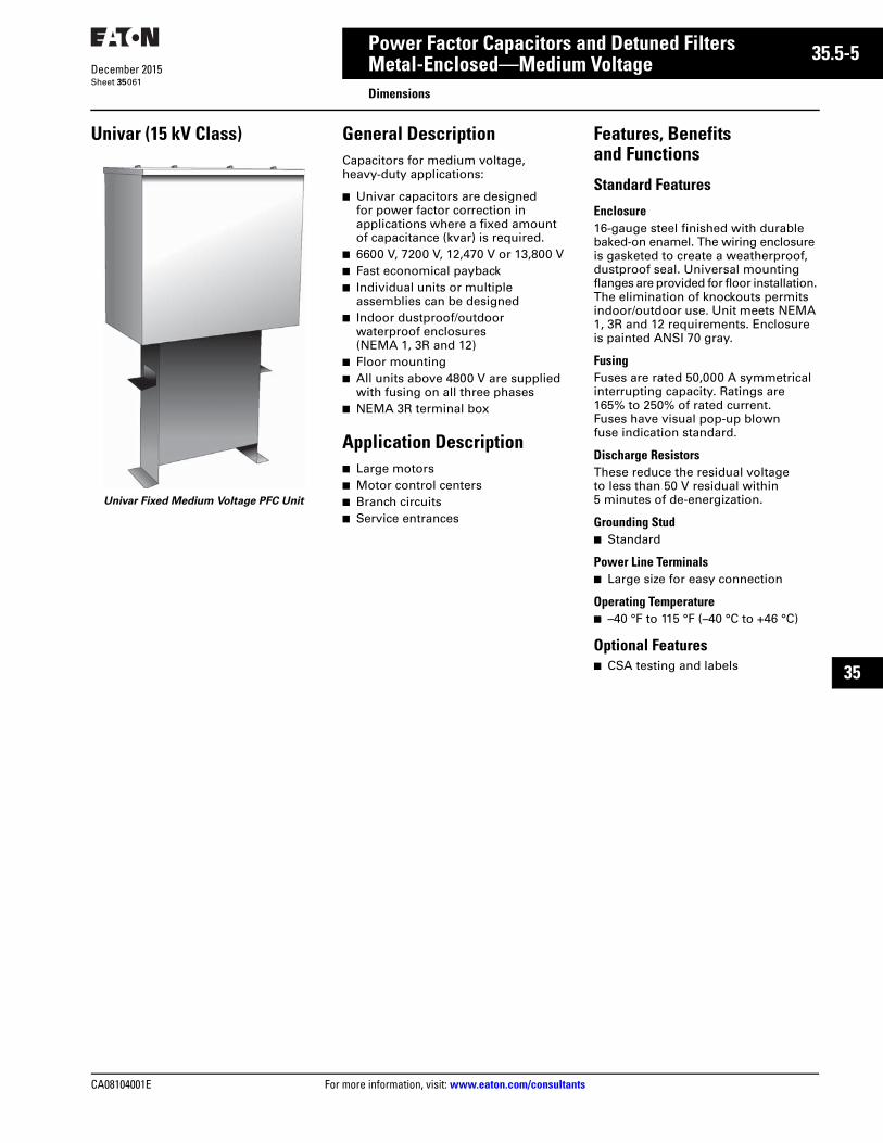
CA08104001E For more information, visit: www.eaton.com/consultants
35.5-5December 2015
Power Factor Capacitors and Detuned Filters
Sheet 35
22
23
24
25
26
27
28
29
30
31
32
33
34
35
36
37
38
39
40
41
42
43
Metal-Enclosed—Medium VoltageDimensions
061
Univar (15 kV Class)
Univar Fixed Medium Voltage PFC Unit
General DescriptionCapacitors for medium voltage, heavy-duty applications:
■ Univar capacitors are designed for power factor correction in applications where a fixed amount of capacitance (kvar) is required.
■ 6600 V, 7200 V, 12,470 V or 13,800 V■ Fast economical payback■ Individual units or multiple
assemblies can be designed■ Indoor dustproof/outdoor
waterproof enclosures (NEMA 1, 3R and 12)
■ Floor mounting■ All units above 4800 V are supplied
with fusing on all three phases■ NEMA 3R terminal box
Application Description■ Large motors■ Motor control centers■ Branch circuits■ Service entrances
Features, Benefits and Functions
Standard Features
Enclosure16-gauge steel finished with durable baked-on enamel. The wiring enclosure is gasketed to create a weatherproof, dustproof seal. Universal mounting flanges are provided for floor installation. The elimination of knockouts permits indoor/outdoor use. Unit meets NEMA 1, 3R and 12 requirements. Enclosure is painted ANSI 70 gray.
FusingFuses are rated 50,000 A symmetrical interrupting capacity. Ratings are 165% to 250% of rated current. Fuses have visual pop-up blown fuse indication standard.
Discharge ResistorsThese reduce the residual voltage to less than 50 V residual within 5 minutes of de-energization.
Grounding Stud■ Standard
Power Line Terminals■ Large size for easy connection
Operating Temperature■ –40 °F to 115 °F (–40 °C to +46 °C)
Optional Features■ CSA testing and labels
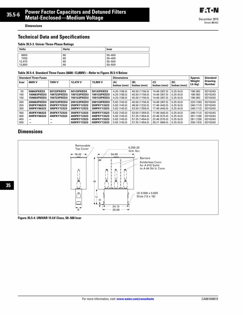
35.5-6
For more information, visit: www.eaton.com/consultants CA08104001E
December 2015
Power Factor Capacitors and Detuned Filters
Sheet 35
22
23
24
25
26
27
28
29
30
31
32
33
34
35
36
37
38
39
40
41
42
43
Metal-Enclosed—Medium VoltageDimensions
062
Technical Data and SpecificationsTable 35.5-3. Univar Three-Phase Ratings
Table 35.5-4. Standard Three Fuses (6600–13,800V)—Refer to Figure 35.5-4 Below
Dimensions
Figure 35.5-4. UNIVAR 15 kV Class, 50–500 kvar
Volts Hertz kvar
66007200
12,47013,800
60606060
50–40050–40050–50050–500
Standard Three Fuses Dimensions Approx.
Weight
Lb (kg)
Standard
Drawing
Numberkvar 6600 V 7200 V 12,470 V 13,800 V (A)
Inches (mm)
(B)
Inches (mm)
(C)
Inches (mm)
(D)
Inches (mm)
50100150
50663FKED3
100663FKED3
150663FKED3
50723FKED3
100723FKED3
150723FKED3
50123FKED3
100123FKED3
150123FKED3
50133FKED3
100133FKED3
150133FKED3
4.25 (108.0)4.25 (108.0)4.25 (108.0)
45.50 (1156.0)45.50 (1156.0)45.50 (1156.0)
14.46 (367.0)14.46 (367.0)14.46 (367.0)
0.25 (6.0)0.25 (6.0)0.25 (6.0)
198 (90)198 (90)198 (90)
5D102435D102435D10243
200250300
200663FKED3
250FKY66323
300FKY66323
200723FKED3
250FKY72323
300FKY72323
200123FKED3
250FKY12323
300FKY12323
200133FKED3
250FKY13323
300FKY13323
5.62 (143.0)5.62 (143.0)5.62 (143.0)
45.50 (1156.0)48.50 (1232.0)53.50 (1359.0)
14.46 (367.0)17.46 (443.0)17.46 (443.0)
0.25 (6.0)0.25 (6.0)0.25 (6.0)
220 (100)246 (112)246 (112)
5D102435D102435D10243
350400450500
350FKY66323
400FKY66323
—
—
350FKY72323
400FKY72323
—
—
350FKY12323
400FKY12323
450FKY12323500FKY12323
350FKY13323
400FKY13323
450FKY13323
500FKY13323
5.62 (143.0)5.62 (143.0)5.62 (143.0)5.62 (143.0)
53.50 (1359.0)57.25 (1454.0)57.25 (1454.0)57.25 (1454.0)
17.46 (443.0)22.46 (570.0)22.46 (570.0)26.21 (666.0)
0.25 (6.0)0.25 (6.0)0.25 (6.0)0.25 (6.0)
246 (112)281 (128)281 (128)336 (153)
5D102435D102435D102435D10243
A
CB
D
0.250-20Grd. Scr.
16.42
RemovableTop Cover
Solderless Conn.for A #10 Solidto A #4 Str’d. Conn.
(2) 0.500 x 0.625Slots [13 x 16]
25.0824.12
34.00Barriers

CA08104001E For more information, visit: www.eaton.com/consultants
35.6-1December 2015
Power Factor Capacitors and Detuned Filters
Sheet 35
22
23
24
25
26
27
28
29
30
31
32
33
34
35
36
37
38
39
40
41
42
43
Metal-Enclosed—Medium VoltageGeneral Description
063
Metal-Enclosed Medium Voltage
Safety and Aesthetics are Just Two Compelling Reasons to Use Metal-Enclosed PFC Systems
Application Description
Utility CustomersMetal-enclosed power factor correc-tion systems are fully assembled, tested and ready for installation. Very little field assembly is required. Installation and maintenance costsfor metal-enclosed systems are low compared to pole and rack mounted capacitor banks. Metal-enclosed systems and harmonic filters are less vulnerable to wildlife and airborne contaminants that can cause tracking and faults. In addition, metal-enclosed systems significantly reduce the risks and the associated liability involving untrained personnel. All live parts are contained in a grounded, key inter-locked enclosure and no internal hardware is accessible. Metal-enclosed systems are aesthetically pleasing due to their low profile, and can be painted to match the surrounding architecture. These are just some of the reasons more and more utilities are using metal-enclosed capacitor and harmonic filter systems.
Industrial CustomersLarge industrial power users can use the benefits associated with medium voltage power factor correction and harmonic filtering. Medium voltage solutions usually support the scale and scope of larger services. Medium voltage applications can be found in the following types of industries as examples: automotives, pulp and paper, plastics, petrochemical and heavy manufacturing.
Individual fixed capacitors provide power factor correction directly at the cause of the problem, such as a large horsepower MV motor. Medium voltage systems allow large industrials to correct power factor at or close to the point of common coupling (PCC), where the utility electrical system meets theirs. This allows correctionfor an entire facility, instead of having to correct at multiple locations. The Eaton NEMA 3R design also allows the system to be placed outdoors, saving valuable manufacturing floor space. The savings can be enormous, in materials, installation costs and floor space. In short, medium voltage solutions provide a cost-effective alternative to many local low voltage power factor correction units, while protecting the customer’s entire electrical distribution system.
Commercial CustomersMany commercial customers are purchasing power from their utility at higher voltages today (2.4–15 kV), and can also take advantage of medium voltage power factor correction systems. These solutions can meet the needs of large office complexes, hospitals and universities, among others. The benefits of safety (key interlocking, no exposed live parts, etc.), and aesthetics (low profile, can be painted to match environment) both meet the needs of these applications where there are large numbers of untrained personnel in proximity of electrical equipment.
AdvantagesEaton’s purchase of the Common-wealth Sprague capacitor systems business, with its over 70 years of market experience, provides a combination that allows the end user to obtain a world-class solution to fill their power factor needs. Quality and reliability are of paramount importance to not only the Eaton engineering team, but are also the backbone of all Eaton products and services. This commitment to quality means the customer can have a great deal of confidence with the medium voltage capacitor orharmonic filter solution from Eaton’s electrical business.
Benefits
Ease of InstallationEaton makes installation easy. All systems are completely assembled in the factory, with all equipment pre-wired and pre-tested for easy on-site installation. Only shipping splits must be connected in the field. Splice kits connect bus systems, and control wiring is easily connected at each enclosure. Current limiting fuses, contactor assemblies, and the incom-ing switch assembly can be removed from the enclosure if needed. Line terminals are completely accessible from the front of the system.
Personnel SafetyPositive mechanical isolating switch with visible disconnect completely grounds and isolates the unit from the line connectors. A screened barrier protects personnel from live parts. All medium voltage doors are mechanically interlocked with the disconnect switch. Key interlocks are provided standard on all enclosure doors, and can be coordinated with upstream disconnect devices. The low voltage control section has a separate door-in-door design, and is segregated from the medium voltage sections so that an operator can work in that section safely.
Ease of MaintenanceAll components are front-accessible, facilitating routine inspection or parts replacement. A viewing window is standard on all compartment doors.
FlexibilitySystems are expandable. The customer can add stages in the future by connecting the phase bus in the field via splice kits. Structures can be bolted together in the field.
Insulated Splice Kits Allow for SimpleInterconnection in the Field
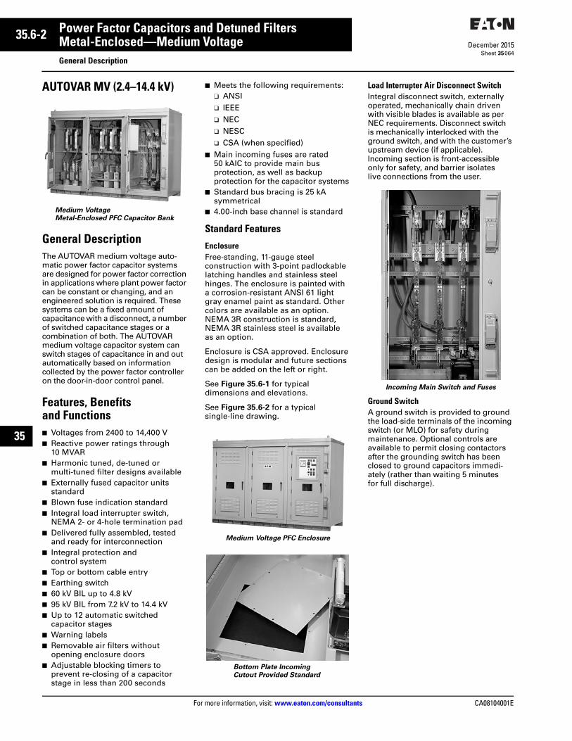
35.6-2
For more information, visit: www.eaton.com/consultants CA08104001E
December 2015
Power Factor Capacitors and Detuned Filters
Sheet 35
22
23
24
25
26
27
28
29
30
31
32
33
34
35
36
37
38
39
40
41
42
43
Metal-Enclosed—Medium VoltageGeneral Description
064
AUTOVAR MV (2.4–14.4 kV)
Medium VoltageMetal-Enclosed PFC Capacitor Bank
General DescriptionThe AUTOVAR medium voltage auto-matic power factor capacitor systems are designed for power factor correction in applications where plant power factor can be constant or changing, and an engineered solution is required. These systems can be a fixed amount of capacitance with a disconnect, a number of switched capacitance stages or a combination of both. The AUTOVAR medium voltage capacitor system can switch stages of capacitance in and out automatically based on information collected by the power factor controller on the door-in-door control panel.
Features, Benefits and Functions■ Voltages from 2400 to 14,400 V■ Reactive power ratings through
10 MVAR■ Harmonic tuned, de-tuned or
multi-tuned filter designs available■ Externally fused capacitor units
standard■ Blown fuse indication standard■ Integral load interrupter switch,
NEMA 2- or 4-hole termination pad■ Delivered fully assembled, tested
and ready for interconnection■ Integral protection and
control system■ Top or bottom cable entry■ Earthing switch■ 60 kV BIL up to 4.8 kV■ 95 kV BIL from 7.2 kV to 14.4 kV■ Up to 12 automatic switched
capacitor stages■ Warning labels■ Removable air filters without
opening enclosure doors■ Adjustable blocking timers to
prevent re-closing of a capacitor stage in less than 200 seconds
■ Meets the following requirements:❑ ANSI❑ IEEE❑ NEC❑ NESC❑ CSA (when specified)
■ Main incoming fuses are rated 50 kAIC to provide main bus protection, as well as backup protection for the capacitor systems
■ Standard bus bracing is 25 kA symmetrical
■ 4.00-inch base channel is standard
Standard Features
EnclosureFree-standing, 11-gauge steel construction with 3-point padlockable latching handles and stainless steel hinges. The enclosure is painted with a corrosion-resistant ANSI 61 light gray enamel paint as standard. Other colors are available as an option. NEMA 3R construction is standard, NEMA 3R stainless steel is available as an option.
Enclosure is CSA approved. Enclosure design is modular and future sections can be added on the left or right.
See Figure 35.6-1 for typical dimensions and elevations.
See Figure 35.6-2 for a typical single-line drawing.
Medium Voltage PFC Enclosure
Bottom Plate IncomingCutout Provided Standard
Load Interrupter Air Disconnect SwitchIntegral disconnect switch, externally operated, mechanically chain driven with visible blades is available as per NEC requirements. Disconnect switchis mechanically interlocked with the ground switch, and with the customer’s upstream device (if applicable). Incoming section is front-accessible only for safety, and barrier isolates live connections from the user.
Incoming Main Switch and Fuses
Ground SwitchA ground switch is provided to ground the load-side terminals of the incoming switch (or MLO) for safety during maintenance. Optional controls are available to permit closing contactors after the grounding switch has been closed to ground capacitors immedi-ately (rather than waiting 5 minutes for full discharge).

CA08104001E For more information, visit: www.eaton.com/consultants
35.6-3December 2015
Power Factor Capacitors and Detuned Filters
Sheet 35
22
23
24
25
26
27
28
29
30
31
32
33
34
35
36
37
38
39
40
41
42
43
Metal-Enclosed—Medium VoltageGeneral Description
065
Vacuum SwitchesOn 2.4 to 4.8 kV multi-stage capacitor systems, each stage is controlled by low maintenance Eaton “SL” AMPGARD three-pole vacuum contactors.
On 6.6 to 14.4 kV multi-stage capacitor systems, each stage is controlled by low maintenance single-pole vacuum switches.
15 kV Switched Capacitor Stage Enclosure
Vacuum ContactorsThe type SL power contactors were designed and engineered specifically for use in AMPGARD starters. They are self-supporting, compact, three-pole vacuum contactors. The SL contactor uses a solid-state control board, allow-ing the user maximum flexibility to change control voltages and dropout times in the field simply by adjusting DIP switch settings. The SL contactor is available for 2.4 –4.8 kV volts at ratings of 200 A and 800 A (the highest rated 800 A contactor available), and contactor interruption ratings of 8500 A allowing for higher levels of coordination with power fuses.
5 kV Switched Capacitor Stage Enclosure
Individual Capacitor FusingEach capacitor is externally fused with current limiting fuses. Fuses are equipped with blown fuse indication. Internally fused capacitors are also available as an option.
Fuses are rated for capacitor protection. Standard fuses are rated 50 kAIC.
Environmental Controls■ Exhaust fans: Exhaust fans are
provided for forced air ventilation of all enclosures as standard
■ Thermal controls: Thermostats are included as standard to help maintain an acceptable internal environment for all components
■ Space heaters: Space heaters are provided to control moisture and humidity inside all enclosures
■ Each compartment has individual thermostats for fan and space heater controls
CapacitorsLow loss, double-bushing capacitors that meet or exceed IEC 871, IEEE Std. 18 and CSA standards are supplied. Capacitors are available in delta, ungrounded wye or solidly grounded wye. The dielectric fluid is environmentally friendly, biodegrad-able, non-PCB. Capacitor units are equipped with internal discharge resistors which reduce the residual voltage to less than 50 V within 5 minutes of de-energization.
Filtered UnitsEaton’s medium voltage detuned filter systems are designed for industrial, utility and commercial power systems to improve power factor, increase system capacity and reduce I2R losses. The reactors are typically tuned to the 4.7th harmonic, to mitigate the most damaging 5th level harmonic. This is the most common harmonic produced by six pulse variable speed drives. These filters are designed to the unique specifications of each electrical distribution system. Medium voltage capacitor banks can also be configured with de-tuned anti-resonant detuned filters, typically set to the 4.2nd harmonic. This helps avoid harmonic resonance problems, provides harmonic filtering, and avoids the overloading that is possible with an improperly applied filter.
Detuned Filter Capacitor Stage Enclosure
Key Interlock SystemThe key interlock system controls the sequential operation of the load break switch (or circuit breaker) and the ground switch to permit safe entry into the capacitor system. All capacitor stage enclosures are also interlocked with the ground switch. If applicable, the customer’s upstream disconnect device can be interlocked as well. See Figure 35.6-2 for key interlock opera-tion on a typical single-line drawing.

35.6-4
For more information, visit: www.eaton.com/consultants CA08104001E
December 2015
Power Factor Capacitors and Detuned Filters
Sheet 35
22
23
24
25
26
27
28
29
30
31
32
33
34
35
36
37
38
39
40
41
42
43
Metal-Enclosed—Medium VoltageGeneral Description
066
Blown Fuse Detection SystemA visual pop-up blown fuse detection system is provided as standard.
Control Power TransformerA fused control power transformer rated for 1.5 kVA is provided as standard for protection, control and operation of the capacitor or harmonic filter system.
Surge Protective Device (SPD)An SPD unit is supplied standard for protection of all low voltage controls in the system.
Control PanelA door-in-door NEMA 3R swing-out control panel is provided on the main incoming structure as standard. This unit includes a viewing window so that all controls and information can be viewed without opening the panel. All low voltage controls and logic are accessible from the front of the system, and are isolated from the medium voltage section.
Included:
■ PFC power factor controller■ Multifunction digital meter/relay■ Full voltage LED lights for status,
alarm and trip indication■ Manual stage operation switches■ Any special controls requested by
the customer
Control Panel
Digital ControllerAutomatic metal-enclosed capacitors and harmonic filter systems come equipped with an automatic controller that switches each capacitor stage based upon power factor. The cus-tomer simply programs in the target PF to meet. The controller analyzes current PF, the size of each stage, and turns on and off stages to meet the customer’s programmed target. Power factor controller comes with the following alarms as standards:
■ Over/under compensation■ No current input■ Step fault■ Step warning■ Target power factor not reached■ Vthd harmonics■ Ithd harmonics■ Over/undervoltage
Up to 12 steps of capacitance can be designed into any system. Customers can note this feature when designing for future expansions.
CommunicationsCommunications of power factor data via RS-485. Modbus is available as an option. Communicated information from the controllers:
■ Voltage■ Current■ Target power factor■ Current power factor■ Active power■ Apparent power■ Reactive power■ Number of steps in the circuit■ All alarm status■ All counters■ Time and date
Inrush ReactorsInrush reactors are provided as standard on all switched (non-harmonic filtered) capacitor systems for protection against transients from back-to-back switching. Reactors in harmonic filtered applications provide this same protection.
BusContinuous 1/4 x 2 inch silver-plated copper bus rated 500 A standard is provided throughout the line-up for easy interconnection, field installation and future expansion.
Phase Bus
Continuous 1/4 x 1 inch silver-plated copper ground bus is provided throughout the line-up for easy inter-connection, field installation and future expansion. Ground studs are available in all structures for customer connection.
Continuous Ground Bus with Pad in Each Section
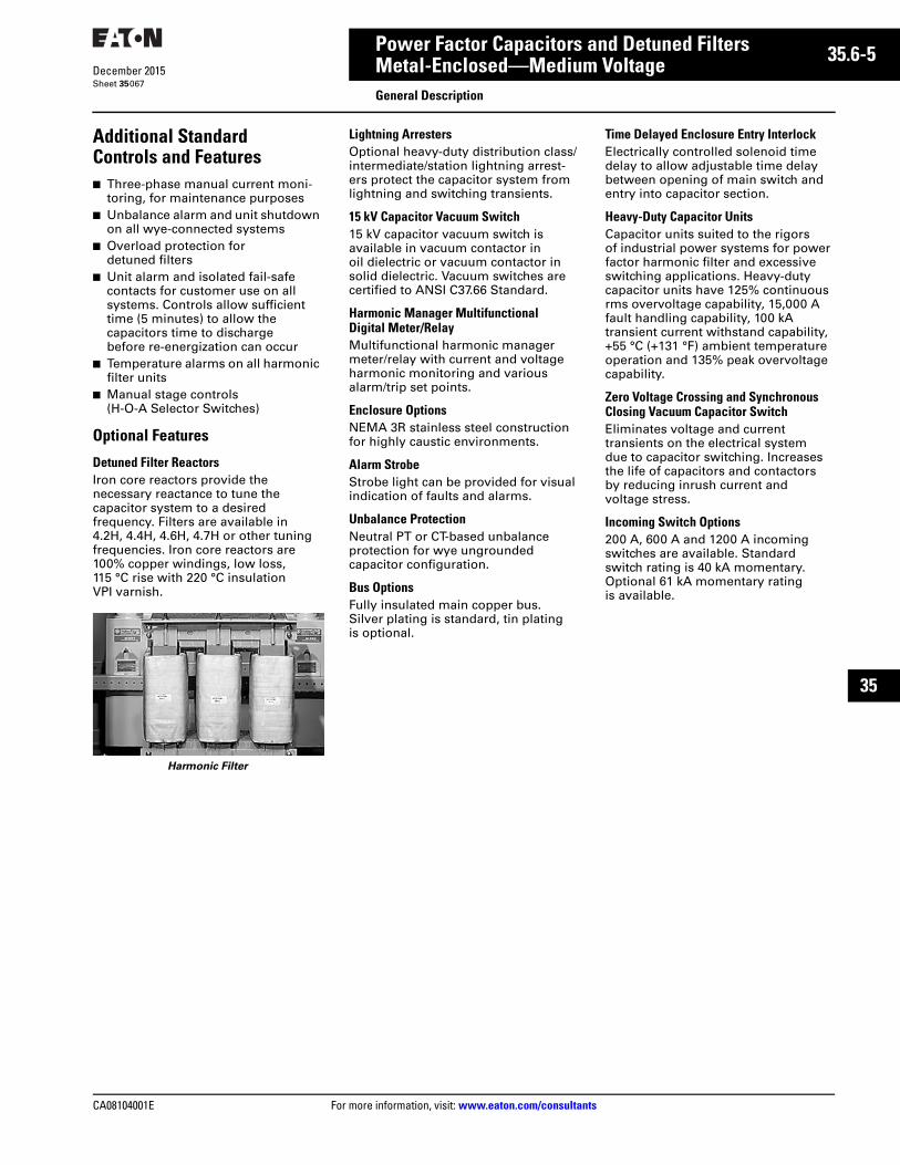
CA08104001E For more information, visit: www.eaton.com/consultants
35.6-5December 2015
Power Factor Capacitors and Detuned Filters
Sheet 35
22
23
24
25
26
27
28
29
30
31
32
33
34
35
36
37
38
39
40
41
42
43
Metal-Enclosed—Medium VoltageGeneral Description
067
Additional Standard Controls and Features■ Three-phase manual current moni-
toring, for maintenance purposes■ Unbalance alarm and unit shutdown
on all wye-connected systems■ Overload protection for
detuned filters■ Unit alarm and isolated fail-safe
contacts for customer use on all systems. Controls allow sufficient time (5 minutes) to allow the capacitors time to discharge before re-energization can occur
■ Temperature alarms on all harmonic filter units
■ Manual stage controls (H-O-A Selector Switches)
Optional Features
Detuned Filter ReactorsIron core reactors provide the necessary reactance to tune the capacitor system to a desired frequency. Filters are available in 4.2H, 4.4H, 4.6H, 4.7H or other tuning frequencies. Iron core reactors are 100% copper windings, low loss, 115 °C rise with 220 °C insulation VPI varnish.
Harmonic Filter
Lightning ArrestersOptional heavy-duty distribution class/intermediate/station lightning arrest-ers protect the capacitor system from lightning and switching transients.
15 kV Capacitor Vacuum Switch15 kV capacitor vacuum switch is available in vacuum contactor in oil dielectric or vacuum contactor in solid dielectric. Vacuum switches are certified to ANSI C37.66 Standard.
Harmonic Manager Multifunctional Digital Meter/RelayMultifunctional harmonic manager meter/relay with current and voltage harmonic monitoring and various alarm/trip set points.
Enclosure OptionsNEMA 3R stainless steel construction for highly caustic environments.
Alarm StrobeStrobe light can be provided for visual indication of faults and alarms.
Unbalance ProtectionNeutral PT or CT-based unbalance protection for wye ungrounded capacitor configuration.
Bus OptionsFully insulated main copper bus. Silver plating is standard, tin plating is optional.
Time Delayed Enclosure Entry InterlockElectrically controlled solenoid time delay to allow adjustable time delay between opening of main switch and entry into capacitor section.
Heavy-Duty Capacitor UnitsCapacitor units suited to the rigors of industrial power systems for power factor harmonic filter and excessive switching applications. Heavy-duty capacitor units have 125% continuous rms overvoltage capability, 15,000 A fault handling capability, 100 kA transient current withstand capability, +55 °C (+131 °F) ambient temperature operation and 135% peak overvoltage capability.
Zero Voltage Crossing and Synchronous Closing Vacuum Capacitor SwitchEliminates voltage and current transients on the electrical systemdue to capacitor switching. Increases the life of capacitors and contactors by reducing inrush current and voltage stress.
Incoming Switch Options200 A, 600 A and 1200 A incoming switches are available. Standard switch rating is 40 kA momentary. Optional 61 kA momentary rating is available.

35.6-6
For more information, visit: www.eaton.com/consultants CA08104001E
December 2015
Power Factor Capacitors and Detuned Filters
Sheet 35
22
23
24
25
26
27
28
29
30
31
32
33
34
35
36
37
38
39
40
41
42
43
Metal-Enclosed—Medium VoltageDimensions
068
Dimensions
Figure 35.6-1. Typical Engineered Metal-Enclosed Power Factor Correction System Dimensional Data
Shipping SplitIncoming Main Section
Mai
n S
wit
chG
rou
nd
Sw
itch
92.56(2351.0)
90.33(2294.4)
K1
K1
D1D2D3
Door InterlocksD2D2
180.80(4592.3)
Front Elevation8 Tieddown Pointsper EnclosureFront and Rearfor 1/2 Inch Hardware Rear Access Doors Optional
Base Channel40-Inches High
1.50(38.1)(Typ)
45.00(1143.0)
DangerHigh Voltage
Keep Out
Bottom PowerCable Entry
Right Side Elevation
49.10(1247.1)
NAMEPLATE
DANGER
CAUTION
DANGER
CAUTION CAUTION
DANGERDANGER
CAUTION
D1
DangerHigh Voltage
Keep Out
DangerHigh Voltage
Keep Out
DangerHigh Voltage
Keep Out
Control Panel
D3
13.50(342.9)
15.00(381.0)
13.50(342.9)
49.00(1244.6)
18.00(457.2)
21.79(553.5)
18.00(457.2)
Bottom EntryCover Plate
5.09(129.3)
9.07(230.4)
1.00(25.4)
Front Access 5 Foot Clearance
Floor Plan
Top View
Top EntryControlConduit
4.00 x 4.00
4.00(101.6)
Top EntryMV Conduit
Area19.00
(482.6)
16.00(406.4)
13.00(330.2)
15.00(381.0)
38.00(965.2)
Top PowerCable Entry
Lifting Eyes
24.00(609.6)
18.00(457.2)Customer
CableTermination(ApproximateLocation, SeeActual Unitfor ExactDimensions)
Gourd Bus1/4-inch x 1-inch
Base Channel

CA08104001E For more information, visit: www.eaton.com/consultants
35.6-7December 2015
Power Factor Capacitors and Detuned Filters
Sheet 35
22
23
24
25
26
27
28
29
30
31
32
33
34
35
36
37
38
39
40
41
42
43
Metal-Enclosed—Medium VoltageLayout Dimensions
069
Figure 35.6-2. Typical Medium Voltage Automatic Power Factor Correction Single-Line Drawing
Alarm or Trip
CapacitorCapacitorCapacitorDelta/Wye Delta/Wye Delta/Wye
Fuse
Reactor
ContactorVacuum
59
TransformerUtility
Utility Line
A-Phase 1
CT
Plant Loads
Feeder Breaker K0
B & CTap On
1-Phase
MainCPT
ControllerPower Factor
BLR-CM
K1
K1K-K Interlock
SwitchGround
Switch
K0
K-K Interlock
ControlS3S2S1
3
CT1 46 Relays
C1
S1
S1
EnclosureDoor
C1
K-K Interlock (Optional)
AMAS
Main Breaker

35.6-8
For more information, visit: www.eaton.com/consultants CA08104001E
December 2015
Power Factor Capacitors and Detuned Filters
Sheet 35
22
23
24
25
26
27
28
29
30
31
32
33
34
35
36
37
38
39
40
41
42
43
070
This page intentionally left blank.


![Untitled-1 [aoneelectric.co.in]aoneelectric.co.in/web/pdf/schneider/power_factor_correction.pdf · Power Factor Correction Products Detuned Filter Application Capacitors Description](https://img.pdfslide.us/doc/110x75/5c49bdaf93f3c34aee529c36/untitled-1-power-factor-correction-products-detuned-filter-application-capacitors.jpg)