Embed Size (px)
Citation preview
DSHM
DSHI
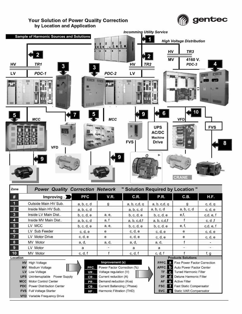
Your Solution in
POWER FACTOR CORRECTIONand
POWER QUALITY CORRECTION
GLOBAL SOLUTION INENERGY MANAGEMENT
PRODUCT APPLICATIONGUIDE

Table of Contents
Gentec LV Capacitors ..........................................................................................................................................................................................2
Type DSHI Low Voltage Capacitor Units ..................................................................................................................................................4
Type DSHM Low Voltage Banks ....................................................................................................................................................................6
Type C100 LV Automatic Switched Banks ..............................................................................................................................................8
Power Quality Solution with: FT100, FT200 reactive filter, FT400 active filter and FT300 dynamic compensation ................................................................................................................10
HVCE Series medium Voltage 3 Phase Capacitors unit and C1000 Series bank ............................................................12
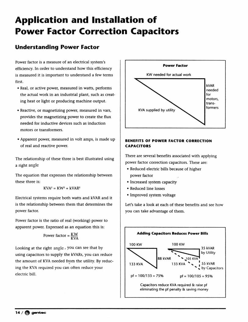
Application and Installation of Power Factor Correction Capacitors
Understanding Power Factor ......................................................................................................................................................................14
Determining the kVAR Requirements for Improving System Power Factor....................................................................17
Installing Capacitors in the Plant ............................................................................................................................................................18
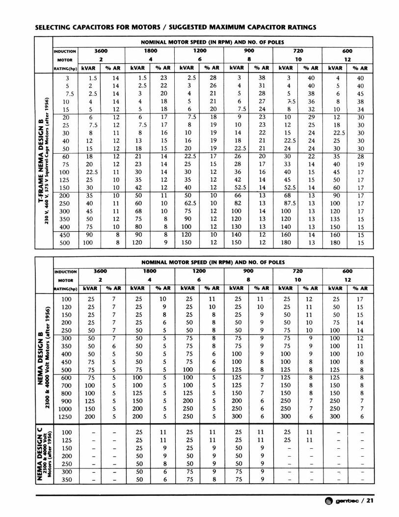
Selecting Capacitors for Motors ................................................................................................................................................................20
Suggested Wire Sizes and protective Device Ratings ..................................................................................................................22
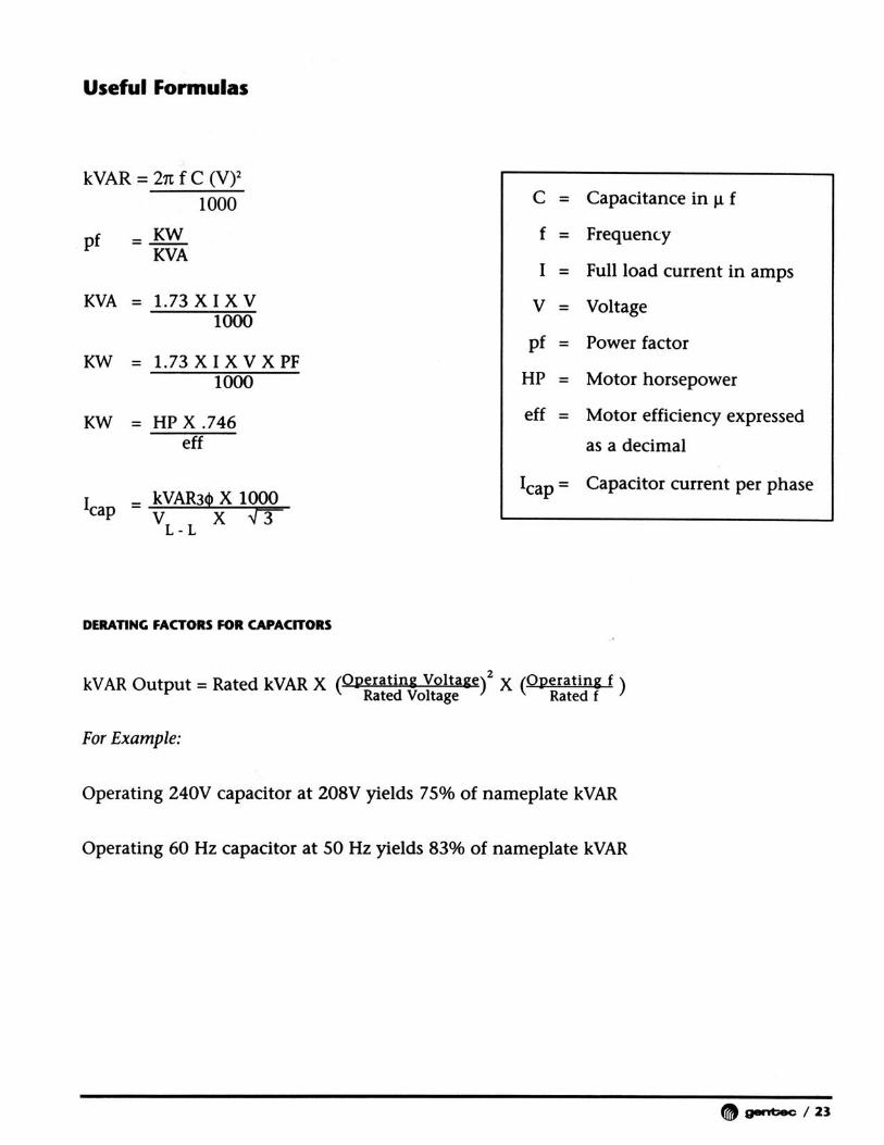
Useful Formulas....................................................................................................................................................................................................23
Power Factor Controller ................................................................................................................................................................................24
/ 1

The new generation of lowvoltage capacitors
Nokian Capacitors has manufactured self healing dry typedlow voltage capacitors since 1980. Today Nokian Capacitorsmanufactures low voltage units having rated voltages from200V to 1000V for both frequencies 50Hz and 60Hz. Forexample, they can have the following applications:
- Delta or star connected 3-phase units to be used forpower factor correction in all kind of capacitor banksincluding detuned and tuned filters
- 1-phase units to be used e.g. in heating installations
- Capacitors units for special applications (trains etc.)
In the design and manufacturing of the new cool type capac-itor unit (L- and N-Series) the latest knowledge in raw mate-rials and processing has been utilised. While choosing rawmaterials and manufacturing processes the quality of the endproduct has been the first priority. As a proof of our contin-uous commitment to quality, Nokian Capacitors was award-ed the Quality Certificate ISO 9001 in December 1993which is followed-up with twice yearly audits. Capacitorunits have been type tested according to IEC 831-1 and IEC831-2 and they have CE-conformity marking and UL andCSA approval.
Because the high temperature of the plastic insulation mate-rial is know to lead to its premature ageing, one of the maintargets in the design of the new cool type capacitor unit wasto find a construction having a low temperature rise whichhas been reached by the following means:
EXCLUSIVE HEAT TRANSFER PACKAGE:
A - Losses of the elements have been minimised using bymean of winding design and using short solid copperterminals.
B - Losses of the wiring have been minimised using solidcopper bus bars and thick copper wires with low currentdensity for internal connection in the capacitor unit.
C - Elements assembled in the steel container using a spac-er to separate elements from each other.
D - The split design of the container allows much better cooling due to 40% increase in the cooling sur-face.
Safety has been also an important guideline in the design themain safety features being:
E- The capacitor is completely encased in the steel con-tainer.
F- The capacitor unit has been provided with two level pro-tection comprised of individually fused elements andnon-flammable filling around the elements in largercapacitor units which displaces oxygen and absorbsenergy in failure situations.
G- Over 10 coolling surfaces.
The new arrangement of the terminals allows easy connec-tion and the design of the discharge resistors (discharge timeto 50V is less than 60 sec.) allows the capacitor units to beeasily used in automatically controlled capacitor banks.
LOW VOLTAGE POWER CAPACITORS:
Low voltage power capacitors are manufactured by usingthe latest methods. Capacitor elements of metallizedpolypropylene film are self-healing and dry without impreg-nation liquid. Each capacitor element is individually pro-tected with patented internal protection.
Capacitors have low losses, and are constructed to be lightin weight. The low voltage power capacitors comply withmost national and international standards.
CONSTRUCTION
The DSHI capacitor consists of a number of low loss capac-itor cells connected to provide the required three phase out-put. These cells are wound from metallized polypropylenefilm. After winding, the cell ends are zinc sprayed to providethe best electrical contact between the turns of the winding,and connection wires are soldered to the zinc end surfaces.The winding is then placed in a thermoplastic resin casewhich is filled with a polyurethane resin and allowed toharden. The finished cells are wired for the required threephase output and assembled in a steel enclosure.
HOUSING
All capacitor units are supplied in a powder epoxy paintedsteel case. Solderless terminal connectors and dischargeresistors are enclosed in an indoor/outdoor terminal com-partment.
Because DSHI Serie capacitors contain no liquid there is nodanger of a spill in the unlikely event of a rupture.
2 /

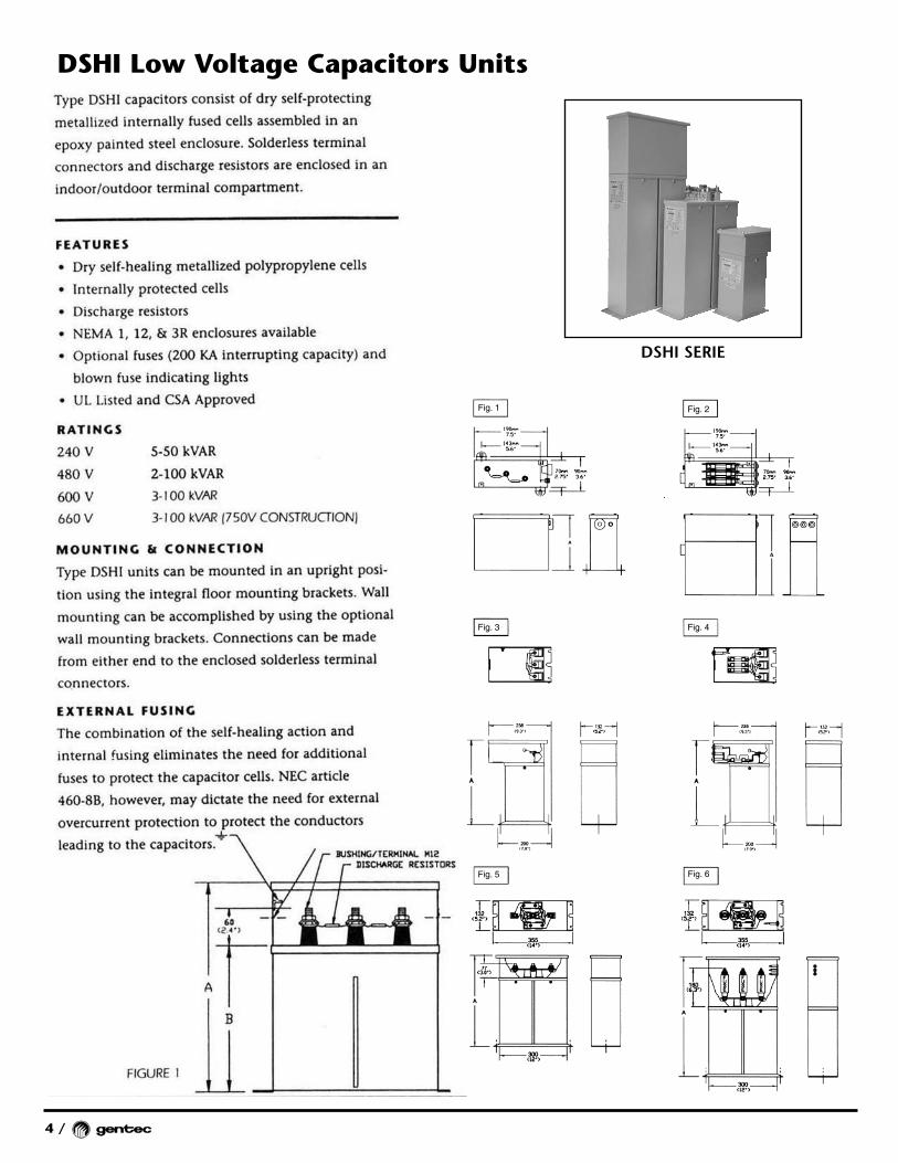
FEATURES
ENVIRONMENTALLY SAFE
Although the elements used in the DSHI capacitor are treat-ed with silicon oil there is no free liquid. Hence in theextremely unlikely event of an element rupture there is norisk of leaks of pollution.
SELF-PROTECTING
Extensive testing on DSHI capacitors with elements pur-posely short circuited by driving a nail through the elementcase has shown that the impedance of the lead connectionsand the element itself will limit the fault current to valuewithin the self-healing capabilities of the elements. Theenergy discharged into the puncture causes the very thinlayer of metal deposited on the polypropylene film to vapor-ize around the area of the fault creating an open circuit andclearing the fault (See Figure 1). This self-healing action iscompleted in ten micro seconds. The capacitors are also pro-tected by an internal fuse element within the cell (See Figure2). This combination of self-healing action and internal fus-ing eliminates the need for additional fuses to protect thecapacitor cells. NEC article 460-8B, however, may dictatethe need for external overcurrent protection to protect theconductors leading to the capacitors.
TEMPERATURE
The DSHI capacitor is designed to operate over an ambienttemperature range of -40 degrees C to +50 degrees C.
OVERVOLTAGE
All DSHI capacitors are suitable for continuous operation at110 percent of the nameplate voltage (RMS including har-monics).
OVERCURRENT
All DSHI capacitors are suitable for continuous operation at135 percent of the rated nameplate current (including har-monics).
DISCHARGE RESISTORS
All power capacitors are equipped with discharge resistorsto discharge the capacitor when de-energized. For 600 voltsand below, the residual voltage is reduced to 50 volts or lesswithin one minute of de-energization. For units above 600volts, the residual voltage is reduced to 50 volts or less with-in 5 minutes.
/ 3
Metallized electrodes
Metallized film
Metallized polypropylene film
Fuse
Film dielectric
Self-healing
Figure 1
Figure 2
4 /
DSHI Low Voltage Capacitors Units
DSHI SERIE
Fig. 1 Fig. 2
Fig. 3 Fig. 4
Fig. 5 Fig. 6
Gentec Products and App Guide 15/06/05 08:24 Page 4
/ 5
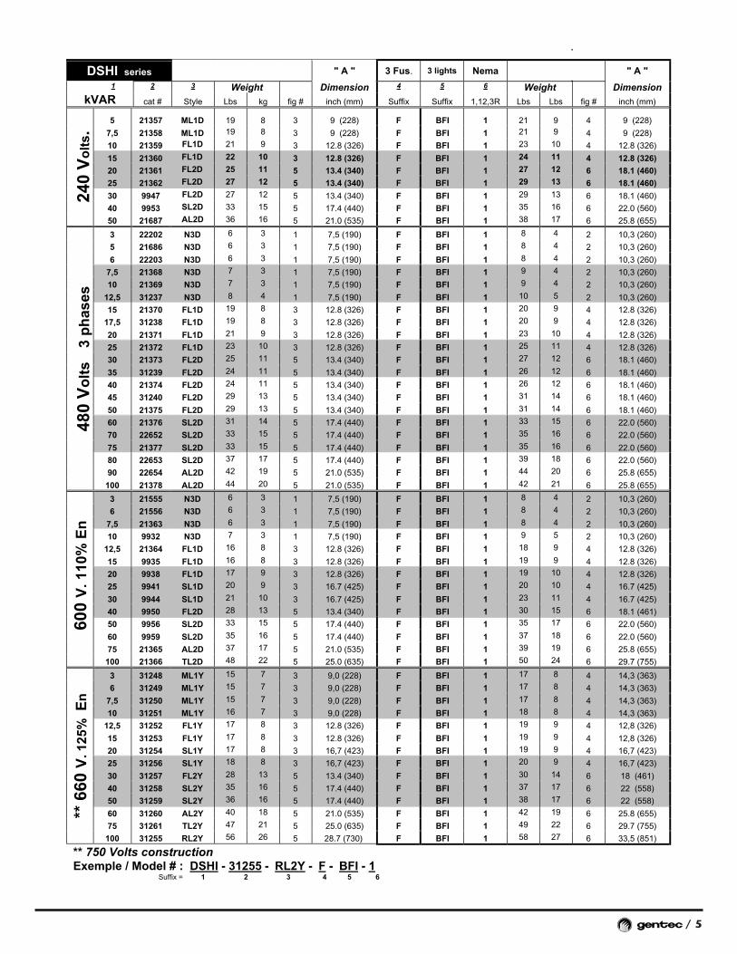
DSHI series " A " 3 Fus. 3 lights Nema " A "
1 2 3 Weight Dimension 4 5 6 Weight DimensionkVAR cat # Style Lbs kg fig # inch (mm) Suffix Suffix 1,12,3R Lbs Lbs fig # inch (mm)
5 21357 ML1D 19 8 3 9 (228) F BFI 1 21 9 4 9 (228)
7,5 21358 ML1D 19 8 3 9 (228) F BFI 1 21 9 4 9 (228)
10 21359 FL1D 21 9 3 12.8 (326) F BFI 1 23 10 4 12.8 (326)
15 21360 FL1D 22 10 3 12.8 (326) F BFI 1 24 11 4 12.8 (326)
20 21361 FL2D 25 11 5 13.4 (340) F BFI 1 27 12 6 18.1 (460)
25 21362 FL2D 27 12 5 13.4 (340) F BFI 1 29 13 6 18.1 (460)
30 9947 FL2D 27 12 5 13.4 (340) F BFI 1 29 13 6 18.1 (460)
40 9953 SL2D 33 15 5 17.4 (440) F BFI 1 35 16 6 22.0 (560)
240
Vo
lts.
50 21687 AL2D 36 16 5 21.0 (535) F BFI 1 38 17 6 25.8 (655)
3 22202 N3D 6 3 1 7,5 (190) F BFI 1 8 4 2 10,3 (260)
5 21686 N3D 6 3 1 7,5 (190) F BFI 1 8 4 2 10,3 (260)
6 22203 N3D 6 3 1 7,5 (190) F BFI 1 8 4 2 10,3 (260)
7,5 21368 N3D 7 3 1 7,5 (190) F BFI 1 9 4 2 10,3 (260)
10 21369 N3D 7 3 1 7,5 (190) F BFI 1 9 4 2 10,3 (260)
12,5 31237 N3D 8 4 1 7,5 (190) F BFI 1 10 5 2 10,3 (260)
15 21370 FL1D 19 8 3 12.8 (326) F BFI 1 20 9 4 12.8 (326)
17,5 31238 FL1D 19 8 3 12.8 (326) F BFI 1 20 9 4 12.8 (326)
20 21371 FL1D 21 9 3 12.8 (326) F BFI 1 23 10 4 12.8 (326)
25 21372 FL1D 23 10 3 12.8 (326) F BFI 1 25 11 4 12.8 (326)
30 21373 FL2D 25 11 5 13.4 (340) F BFI 1 27 12 6 18.1 (460)
35 31239 FL2D 24 11 5 13.4 (340) F BFI 1 26 12 6 18.1 (460)
40 21374 FL2D 24 11 5 13.4 (340) F BFI 1 26 12 6 18.1 (460)
45 31240 FL2D 29 13 5 13.4 (340) F BFI 1 31 14 6 18.1 (460)
50 21375 FL2D 29 13 5 13.4 (340) F BFI 1 31 14 6 18.1 (460)
60 21376 SL2D 31 14 5 17.4 (440) F BFI 1 33 15 6 22.0 (560)
70 22652 SL2D 33 15 5 17.4 (440) F BFI 1 35 16 6 22.0 (560)
75 21377 SL2D 33 15 5 17.4 (440) F BFI 1 35 16 6 22.0 (560)
80 22653 SL2D 37 17 5 17.4 (440) F BFI 1 39 18 6 22.0 (560)
90 22654 AL2D 42 19 5 21.0 (535) F BFI 1 44 20 6 25.8 (655)
480
Vo
lts
3 p
has
es
100 21378 AL2D 44 20 5 21.0 (535) F BFI 1 42 21 6 25.8 (655)
3 21555 N3D 6 3 1 7,5 (190) F BFI 1 8 4 2 10,3 (260)
6 21556 N3D 6 3 1 7,5 (190) F BFI 1 8 4 2 10,3 (260)
7,5 21363 N3D 6 3 1 7,5 (190) F BFI 1 8 4 2 10,3 (260)
10 9932 N3D 7 3 1 7,5 (190) F BFI 1 9 5 2 10,3 (260)
12,5 21364 FL1D 16 8 3 12.8 (326) F BFI 1 18 9 4 12.8 (326)
15 9935 FL1D 16 8 3 12.8 (326) F BFI 1 19 9 4 12.8 (326)
20 9938 FL1D 17 9 3 12.8 (326) F BFI 1 19 10 4 12.8 (326)
25 9941 SL1D 20 9 3 16.7 (425) F BFI 1 20 10 4 16.7 (425)
30 9944 SL1D 21 10 3 16.7 (425) F BFI 1 23 11 4 16.7 (425)
40 9950 FL2D 28 13 5 13.4 (340) F BFI 1 30 15 6 18.1 (461)
50 9956 SL2D 33 15 5 17.4 (440) F BFI 1 35 17 6 22.0 (560)
60 9959 SL2D 35 16 5 17.4 (440) F BFI 1 37 18 6 22.0 (560)
75 21365 AL2D 37 17 5 21.0 (535) F BFI 1 39 19 6 25.8 (655)
600
V. 1
10%
En
100 21366 TL2D 48 22 5 25.0 (635) F BFI 1 50 24 6 29.7 (755)
3 31248 ML1Y 15 7 3 9,0 (228) F BFI 1 17 8 4 14,3 (363)
6 31249 ML1Y 15 7 3 9,0 (228) F BFI 1 17 8 4 14,3 (363)
7,5 31250 ML1Y 15 7 3 9,0 (228) F BFI 1 17 8 4 14,3 (363)
10 31251 ML1Y 16 7 3 9,0 (228) F BFI 1 18 8 4 14,3 (363)
12,5 31252 FL1Y 17 8 3 12.8 (326) F BFI 1 19 9 4 12,8 (326)
15 31253 FL1Y 17 8 3 12.8 (326) F BFI 1 19 9 4 12,8 (326)
20 31254 SL1Y 17 8 3 16,7 (423) F BFI 1 19 9 4 16,7 (423)
25 31256 SL1Y 18 8 3 16,7 (423) F BFI 1 20 9 4 16,7 (423)
30 31257 FL2Y 28 13 5 13.4 (340) F BFI 1 30 14 6 18 (461)
40 31258 SL2Y 35 16 5 17.4 (440) F BFI 1 37 17 6 22 (558)
50 31259 SL2Y 36 16 5 17.4 (440) F BFI 1 38 17 6 22 (558)
60 31260 AL2Y 40 18 5 21.0 (535) F BFI 1 42 19 6 25.8 (655)
75 31261 TL2Y 47 21 5 25.0 (635) F BFI 1 49 22 6 29.7 (755)
** 6
60 V
. 125
% E
n
100 31255 RL2Y 56 26 5 28.7 (730) F BFI 1 58 27 6 33,5 (851)
** 750 Volts constructionExemple / Model # : DSHI - 31255 - RL2Y - F - BFI - 1
Suffix = 1 2 3 4 5 6
6 /
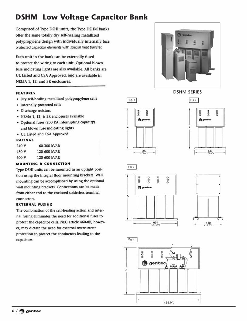
DSHM Low Voltage Capacitor Bank
Fig. 1 Fig. 2
Fig. 3
Fig. 4
DSHM SERIES

/ 7
Model no.. option option Option DIMENSION
DSHM series styleType ..
1,12,3R 3 Fuses 3 Lights " A " Weight
kVAR cat # Suffixe Suffixe Suffixe Suffixe fig # pouce (mm) Lbs kg
60 2-9947 FL2D 1 F BFI 1 23.0 (583) 55 25
80 2-9953 SL2D 1 F BFI 1 26.9 (683) 68 31
100 2-21687 AL2D 1 F BFI 1 30.6 (778) 73 33
120 3-9953 SL2D 1 F BFI 2 26.9 (683) 109 49
150 3-21687 AL2D 1 F BFI 2 30.6 (778) 115 52
200 4-21687 AL2D 1 F BFI 3 30.6 (778) 187 85
225 4-21687-2 AL2D 1 F BFI 4 30.6 (778) 200 91
250 5-21687 AL2D 1 F BFI 4 30.6 (778) 218 99
240
Vo
lts
300 6-21687 AL2D 1 F BFI 4 30.6 (778) 231 105
120 2-21376 SL2D 1 F BFI 1 26.9 (683) 73 33
125 2-21377-5 SL2D 1 F BFI 1 26.9 (683) 73 33
130 2-22652-6 SL2D 1 F BFI 1 26.9 (683) 73 33
140 2-22652 SL2D 1 F BFI 1 26.9 (683) 74 34
150 2-21377 SL2D 1 F BFI 1 26.9 (683) 76 35
160 2-22653 SL2D 1 F BFI 1 26.9 (683) 83 38
175 2-21378-7 AL2D 1 F BFI 1 30.6 (778) 96 43
180 2-22654 AL2D 1 F BFI 1 30.6 (778) 97 44
200 2-21378 AL2D 1 F BFI 1 30.6 (778) 99 45
210 3-22652 SL2D 1 F BFI 2 26.9 (683) 115 52
225 3-21377 SL2D 1 F BFI 2 26.9 (683) 118 53
240 3-22653 SL2D 1 F BFI 2 26.9 (683) 128 58
250 3-22654-2 AL2D 1 F BFI 2 30.6 (778) 142 68
270 3-22654 AL2D 1 F BFI 2 30.6 (778) 145 65
275 3-21378-7 AL2D 1 F BFI 2 30.6 (778) 148 66
290 3-21378-4 AL2D 1 F BFI 2 30.6 (778) 157 71
300 3-21378 AL2D 1 F BFI 2 30.6 (778) 168 77
320 4-22653 SL2D 1 F BFI 3 26.9 (683) 174 79
360 4-22654 AL2D 1 F BFI 3 30.6 (778) 192 87
400 4-21378 AL2D 1 F BFI 3 30.6 (778) 200 91
430 4-21378-3 AL2D 1 F BFI 3 30.6 (778) 231 105
450 5-22654 AL2D 1 F BFI 4 30.6 (778) 257 117
475 5-21378-7 AL2D 1 F BFI 4 30.6 (778) 284 129
500 5-21378 AL2D 1 F BFI 4 30.6 (778) 288 131
540 6-22654 AL2D 1 F BFI 4 30.6 (778) 290 132
480
Vo
lts
600 6-21378 AL2D 1 F BFI 4 30.6 (778) 299 135
120 2-9959 SL2D 1 F BFI 1 26.9 (683) 69 31
150 2-21365 AL2D 1 F BFI 1 30.6 (778) 73 33
175 2-21366-5 TL2D 1 F BFI 1 34.6 (878) 109 49
200 2-21366 TL2D 1 F BFI 1 34.6 (878) 110 52
225 3-21365 AL2D 1 F BFI 2 30.6 (778) 115 53
250 3-21366-6 TL2D 1 F BFI 2 34.6 (878) 148 67
275 3-21366-5 TL2D 1 F BFI 2 34.6 (878) 148 69
300 3-21366 TL2D 1 F BFI 2 34.6 (878) 150 71
350 4-21366-6 TL2D 1 F BFI 3 34.6 (878) 200 91
375 4-21366-5 TL2D 1 F BFI 3 34.6 (878) 210 93
400 4-21366 TL2D 1 F BFI 3 34.6 (878) 225 95
450 5-21366-6 TL2D 1 F BFI 4 34.6 (878) 230 104
500 5-21366 TL2D 1 F BFI 4 34.6 (878) 235 114
550 6-21366-6 TL2D 1 F BFI 4 34.6 (878) 255 120
600
Vo
lts
600 6-21366 TL2D 1 F BFI 4 34.6 (878) 300 135
Model # = DSHM -6-21366 - AL2D - 12 - F - BFI
Others Power are available on request Contact Gentec factoryType = 1, 12 or 3R
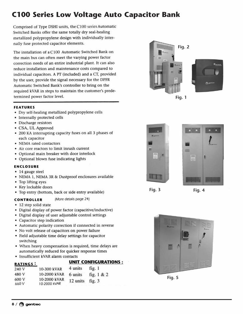
C100 Series Low Voltage Auto Capacitor Bank
8 /
Fig. 3
Fig. 1
Fig. 5
Fig. 2
Fig. 4
/ 9
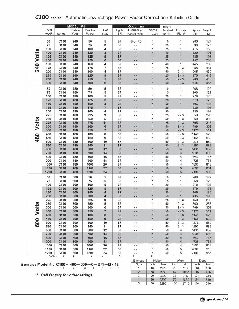
C100 series Automatic Low Voltage Power Factor Correction / Selection Guide
MODEL # # Option (s) BinaryTotal System Reactive # of Lights Breaker or Nema Switched Enclose Approx. WeightkVAR series Volts Power step BFI F.Disconnect 1,12,3R kVAR Fig. # Lbs Kg
50 C100 240 50 5 BFI B or FD 1 10 1 280 12775 C100 240 75 3 BFI - - 1 25 1 390 177100 C100 240 100 4 BFI - - 1 25 1 415 189120 C100 240 120 3 BFI - - 1 40 1 420 191125 C100 240 125 5 BFI - - 1 25 1 435 198150 C100 240 150 6 BFI - - 1 25 1 457 208160 C100 240 160 4 BFI - - 1 40 1 445 202175 C100 240 175 7 BFI - - 1 25 2 - 3 955 434200 C100 240 200 4 BFI - - 1 50 2 - 3 965 439225 C100 240 225 9 BFI - - 1 25 2 - 3 975 443250 C100 240 250 5 BFI - - 1 50 2 - 3 980 445
240
Vo
lts
300 C100 240 300 6 BFI - - 1 50 2 - 3 1000 455
50 C100 480 50 5 BFI - - 1 10 1 268 12275 C100 480 75 5 BFI - - 1 15 1 268 122100 C100 480 100 5 BFI - - 1 20 1 278 126125 C100 480 125 5 BFI - - 1 25 1 379 172150 C100 480 150 3 BFI - - 1 50 1 406 185175 C100 480 175 7 BFI - - 1 25 1 425 193200 C100 480 200 4 BFI - - 1 50 1 435 198225 C100 480 225 9 BFI - - 1 25 2 - 3 650 295250 C100 480 250 5 BFI - - 1 50 2 - 3 660 300275 C100 480 275 11 BFI - - 1 25 2 - 3 695 316300 C100 480 300 6 BFI - - 1 50 2 - 3 789 359350 C100 480 350 7 BFI - - 1 50 2 - 3 1125 511400 C100 480 400 8 BFI - - 1 50 2 - 3 1149 522450 C100 480 450 9 BFI - - 1 50 2 - 3 1165 530500 C100 480 500 10 BFI - - 1 50 2 - 3 1275 580550 C100 480 550 11 BFI - - 1 50 2 - 3 1290 586600 C100 480 600 12 BFI - - 1 50 4 1435 652700 C100 480 700 14 BFI - - 1 50 4 1535 698800 C100 480 800 16 BFI - - 1 50 4 1640 745900 C100 480 900 18 BFI - - 1 50 4 1725 7841000 C100 480 1000 20 BFI - - 1 50 4 1800 8181100 C100 480 1100 22 BFI - - 1 50 5 2000 864
480
Vo
lts
1200 C100 480 1200 24 BFI - - 1 50 5 2100 909
50 C100 600 50 5 BFI - - 1 10 1 268 12275 C100 600 75 5 BFI - - 1 15 1 268 122100 C100 600 100 5 BFI - - 1 20 1 278 126125 C100 600 125 5 BFI - - 1 25 1 379 172150 C100 600 150 5 BFI - - 1 30 1 406 185200 C100 600 200 4 BFI - - 1 50 1 435 198225 C100 600 225 9 BFI - - 1 25 2 - 3 450 205250 C100 600 250 5 BFI - - 1 50 2 - 3 560 255300 C100 600 300 6 BFI - - 1 50 2 - 3 789 359350 C100 600 350 7 BFI - - 1 50 2 - 3 1125 511400 C100 600 400 8 BFI - - 1 50 2 - 3 1149 522450 C100 600 450 9 BFI - - 1 50 2 - 3 1165 530500 C100 600 500 10 BFI - - 1 50 2 - 3 1275 580550 C100 600 550 11 BFI - - 1 50 2 - 3 1290 586600 C100 600 600 12 BFI - - 1 50 4 1435 652700 C100 600 700 14 BFI - - 1 50 4 1535 698800 C100 600 800 16 BFI - - 1 50 4 1640 745900 C100 600 900 18 BFI - - 1 50 4 1725 7841000 C100 600 1000 20 BFI - - 1 50 4 1800 8181100 C100 600 1100 22 BFI - - 1 50 5 2000 910
600
Vo
lts
1200 C100 600 1200 24 BFI - - 1 50 5 2100 955Suffix = 1 2 3 4 5 6 7
Exemple / Model # : C100 - 480 600 6 BFI — — — — B - 121 2 3 4 5 6 7
*** Call factory for other ratings
Enclose Height Wide DeepFig. # Inch Mm Inch Mm Inch Mm
1 48 28 162 78 42 163 90 36 244 90 72 245 90
12201980229022902290
710106791518302745
406406610610610108 24

Due to the many non-linear loads today, modern power sys-tems generate harmonics. They are typically caused byadjustable speed drives, programmable controllers, induc-tion furnaces, UPS, and any other loads with semiconduc-tors. Nuisance fuse blowings, capacitor failures, overheatedwiring and transformers, circuit breaker tripping, telephoneinterference, and motor burnouts are often signs of systemharmonics. These harmonics need to be considered whenapplying capacitors.
Although capacitors do not cause harmonics, improperlyapplying them can aggravate harmonics. Capacitors act as alow impedance path for harmonics. This can cause two prob-lems. The increased current through the capacitor can causeit to fail. Also the increased current can create a resonantcondition in which harmonic currents are magnified.
Gentec FT100, FT200, FT300 and FT400 Series offers foursolutions when harmonics are present in a power system:Harmonic Detuned Filter and Reactive & Active Filters.
LOW VOLTAGE HARMONIC DETUNE FILTERBANKS
Power factor correction by means of conventional capacitorbanks is not always possible in systems affected by harmonics.
The Gentec FT100 Series Harmonic Detuned Filter Bankprovides power factor correction in harmonic rich environ-
ments by combining harmonic duty capable capacitors withiron core reactors. This combination forms a series resonantcircuit tuned to the 4.08th harmonic. This blocking bank alsoacts as a detuned filter removing up to 50% of the lowerorder harmonic currents from the system.
They are CSA and UL Approved and are availaible in bothfixed and automatic switched configurations at 240, 480,and 600 volts in indoor (NEMA 1), outdoor (NEMA 3R),and dustproof enclosures.
LOW VOLTAGE HARMONIC FILTERS
Gentec FT200 and FT400 Series Harmonic Filters are thebest way to targate and eliminate harmonic distortion fromyour power system, while still improving your power factor.
The Reactive filter FT200 are sized to provide power factorcorrection while the iron core reactors are tuned to the 4.7thso the filter forms a very low impedance series resonant circuit at the harmonic frequency or FT400 Active filter for atotal filtration from 3th to 52 th. These harmonic filters arecustom designed for each application using standard compo-nents to ensure the best possible power factor correction at anaffordable price.
The power quality serie solution are available in both fixedand automatic switched configurations at 240, 480, and 600volts in indoor (NEMA 1), outdoor (NEMA 3R), and dust-proof enclosures.
10 /
Power Quality Solution in Low Voltage Harmonic Filters
DS100 & D200 SERIES
Drive Saver

FEATURES
Fixed Harmonic Filters (DS200) andDetuned Filter Banks (DS100)
• UL and CSA Listed Harmonic duty capable dry self-healinginternally protected metallized polypropylene capacitors
• Tuned iron core reactors (to the 4.7th for Harmonic Filtersand to the 4.08th for Detuned Banks)
• 200 KA interrupting capacity fuses• Optional blown fuse indicating lights• NEMA 1, 12, & 3R enclosures available
Automatic Switched Multi-Step HarmonicFilters FT200 and Detuned Banks FT100
• UL and CSA Listed harmonic duty capable dry self-healinginternally protected metallized polypropylene capacitors
• Tuned iron core reactors (to the 4.7th for Harmonic Filtersand to the 4.08th for Detuned Banks)
• NEMA rated contactors• 12 step solid state control (see page for details)• 200 KA interrupting capacity fuses on all 3 phases of each
capacitor• NEMA 1, 3R, & Dustproof enclosures available• Top lifting eyes• Key lockable doors• Optional main breaker with door interlock• Optionnal blown fuse indicating lights• CSA and UL Approved
DYNAMIC COMPENSATION SYSTEM FT300 and ACTIVE FILTER FT400
Those systems are also available for special application like:- FT300 Quick reactive power requirement and phase balancing- FT400 Total harmonic filtration on the 3 phases
and neutral.(contact factory for your application)
RATINGS
Because of Gentec’s “custom approach” using standard com-ponents, any size fixed or switched capacitor bank can besupplied as a Harmonic Detuned, Filter Bank or Active filter
SYSTEM HARMONIC INFORMATION
Reactive filter or Active filter should not be applied withoutfirst performing an analysis to determine the specific needsof your power system. To properly do this, certain informa-tion is needed.
Network Characteristics (include a one line diagram)• Main power distribution transformer KVA, voltage,
impedance, and frequency• Total system load• Existing and target power factor• Drive and rectifier information• Existing reactive power on the system• Reactive power to be added
/ 11CALL GENTEC FOR YOUR SOLUTION
FT100 De-tuned Filter
Automatic Switched Bank Automatic Switched Bank
FT200 Tuned Filter
Automatic Dynamic System
FT300 Dynamic Compensation
Total Harmonic Filtration
FT400 Active Filter
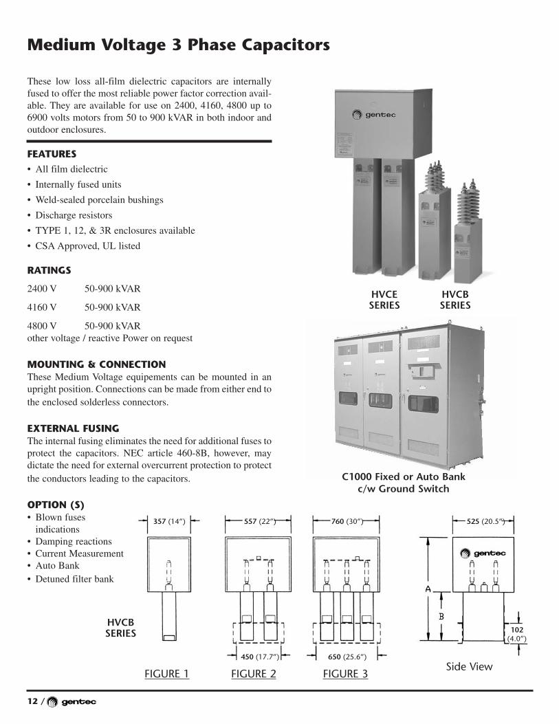
These low loss all-film dielectric capacitors are internallyfused to offer the most reliable power factor correction avail-able. They are available for use on 2400, 4160, 4800 up to6900 volts motors from 50 to 900 kVAR in both indoor and outdoor enclosures.
FEATURES• All film dielectric
• Internally fused units
• Weld-sealed porcelain bushings
• Discharge resistors
• TYPE 1, 12, & 3R enclosures available
• CSA Approved, UL listed
RATINGS
2400 V 50-900 kVAR
4160 V 50-900 kVAR
4800 V 50-900 kVARother voltage / reactive Power on request
MOUNTING & CONNECTIONThese Medium Voltage equipements can be mounted in anupright position. Connections can be made from either end tothe enclosed solderless connectors.
EXTERNAL FUSINGThe internal fusing eliminates the need for additional fuses toprotect the capacitors. NEC article 460-8B, however, maydictate the need for external overcurrent protection to protectthe conductors leading to the capacitors.
OPTION (S)• Blown fuses
indications• Damping reactions• Current Measurement• Auto Bank• Detuned filter bank
12 /
Medium Voltage 3 Phase Capacitors
FIGURE 1 FIGURE 2 FIGURE 3Side View
357 (14”) 557 (22”) 525 (20.5”)760 (30”)
450 (17.7”) 650 (25.6”)
102(4.0”)
C1000 Fixed or Auto Bankc/w Ground Switch
HVCESERIES
HVCBSERIES
HVCBSERIES
/ 13
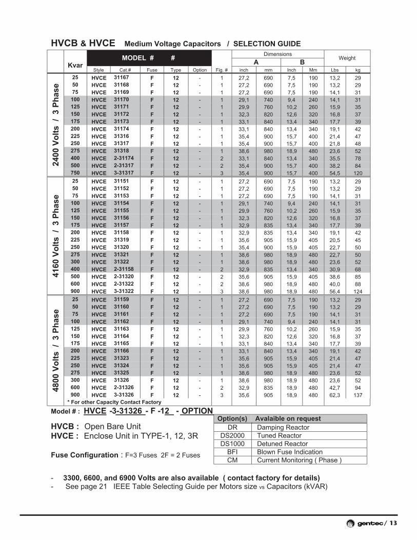
HVCB & HVCE Medium Voltage Capacitors / SELECTION GUIDE
Model # : HVCE - 3-31326 - F - 12 -
HVCB : Open Bare UnitHVCE : Enclose Unit in TYPE-1, 12, 3R
Fuse Configuration : F=3 Fuses 2F = 2 Fuses
- 3300, 6600, and 6900 Volts are also available ( contact factory for details)- See page 21 IEEE Table Selecting Guide per Motors size vs Capacitors (kVAR)
DimensionsMODEL # #
A BWeight
KvarStyle Cat.# Fuse Type Option Fig. # inch mm Inch Mm Lbs kg
25 HVCE 31167 F 12 - 1 27,2 690 7,5 190 13,2 2950 HVCE 31168 F 12 - 1 27,2 690 7,5 190 13,2 2975 HVCE 31169 F 12 - 1 27,2 690 7,5 190 14,1 31100 HVCE 31170 F 12 - 1 29,1 740 9,4 240 14,1 31125 HVCE 31171 F 12 - 1 29,9 760 10,2 260 15,9 35150 HVCE 31172 F 12 - 1 32,3 820 12,6 320 16,8 37175 HVCE 31173 F 12 - 1 33,1 840 13,4 340 17,7 39200 HVCE 31174 F 12 - 1 33,1 840 13,4 340 19,1 42225 HVCE 31316 F 12 - 1 35,4 900 15,7 400 21,4 47250 HVCE 31317 F 12 - 1 35,4 900 15,7 400 21,8 48275 HVCE 31318 F 12 - 1 38,6 980 18,9 480 23,6 52400 HVCE 2-31174 F 12 - 2 33,1 840 13,4 340 35,5 78500 HVCE 2-31317 F 12 - 2 35,4 900 15,7 400 38,2 8424
00 V
olt
s /
3 P
has
e
750 HVCE 3-31317 F 12 - 3 35,4 900 15,7 400 54,5 120
25 HVCE 31151 F 12 - 1 27,2 690 7,5 190 13,2 2950 HVCE 31152 F 12 - 1 27,2 690 7,5 190 13,2 2975 HVCE 31153 F 12 - 1 27,2 690 7,5 190 14,1 31100 HVCE 31154 F 12 - 1 29,1 740 9,4 240 14,1 31125 HVCE 31155 F 12 - 1 29,9 760 10,2 260 15,9 35150 HVCE 31156 F 12 - 1 32,3 820 12,6 320 16,8 37175 HVCE 31157 F 12 - 1 32,9 835 13,4 340 17,7 39200 HVCE 31158 F 12 - 1 32,9 835 13,4 340 19,1 42225 HVCE 31319 F 12 - 1 35,6 905 15,9 405 20,5 45250 HVCE 31320 F 12 - 1 35,4 900 15,9 405 22,7 50275 HVCE 31321 F 12 - 1 38,6 980 18,9 480 22,7 50300 HVCE 31322 F 12 - 1 38,6 980 18,9 480 23,6 52400 HVCE 2-31158 F 12 - 2 32,9 835 13,4 340 30,9 68500 HVCE 2-31320 F 12 - 2 35,6 905 15,9 405 38,6 85600 HVCE 2-31322 F 12 - 2 38,6 980 18,9 480 40,0 88
4160
Vo
lts
/ 3
Ph
ase
900 HVCE 3-31322 F 12 - 3 38,6 980 18,9 480 56,4 124
25 HVCE 31159 F 12 - 1 27,2 690 7,5 190 13,2 2950 HVCE 31160 F 12 - 1 27,2 690 7,5 190 13,2 2975 HVCE 31161 F 12 - 1 27,2 690 7,5 190 14,1 31100 HVCE 31162 F 12 - 1 29,1 740 9,4 240 14,1 31125 HVCE 31163 F 12 - 1 29,9 760 10,2 260 15,9 35150 HVCE 31164 F 12 - 1 32,3 820 12,6 320 16,8 37175 HVCE 31165 F 12 - 1 33,1 840 13,4 340 17,7 39200 HVCE 31166 F 12 - 1 33,1 840 13,4 340 19,1 42225 HVCE 31323 F 12 - 1 35,6 905 15,9 405 21,4 47250 HVCE 31324 F 12 - 1 35,6 905 15,9 405 21,4 47275 HVCE 31325 F 12 - 1 38,6 980 18,9 480 23,6 52300 HVCE 31326 F 12 - 1 38,6 980 18,9 480 23,6 52600 HVCE 2-31326 F 12 - 2 32,9 835 18,9 480 42,7 94900 HVCE 3-31326 F 12 - 3 35,6 905 18,9 480 62,3 137
4800
Vo
lts
/ 3
Ph
ase
* For other Capacity Contact Factory
Option(s) Avalaible on requestDR Damping Reactor
DS2000 Tuned ReactorDS1000 Detuned Reactor
BFI Blown Fuse IndicationCM Current Monitoring ( Phase )
OPTION


24 /
TECHNICAL SPECIFICATIONPower supply 120V±15%, burden 8 VAMeasurement voltage 120V±15%
230V @ 460V. ±15%384V @ 750V. ±15%
Connection with or without neutral line50Hz or 60Hz ± 2Hz
Frequency automatic selectionCT 1 & 5 A, burden 0.7 VAManual operation Manual operation with
momentary push buttonOperational sequence User-selectable from menu
normal 1:2:4:4stack 1:1:1:1circulating A 1:1:1:1circulating B 1:1:1:1Smart 1:2:2:2
Communication capacity NC12 RS 485 ModbusAdaptor (optional)
Output relays 2.0 A, 400 VAC, normallyControl Fan relay open
0.3 A, 110 VDC5.0 A, 30 VDC
Alarm relay open0.3 A, 110 VDC
Accuracy class C12: 1.5%C6: 2.5%
Ambient temperature 0…+ 60°CProtection class IP 40 at panel installation
IP 20 DIN-rail installationDimensions 144X144 mm, depth 90 mmPanel cut-out 138X138 mm, -0…+1 mmWeight 0.9 kg
TECHNICAL INFORMATION• Automatic search of C/K values• Possibility to set different C/K values for inductive
and capacitive side*)• Easy-to-use menu-driven user interface• 16 character alphanumeric display• THD (u) (I) measurement and alarm*)• Irms/In measurement and alarm• Measurement and alarm of low capacitor output*)• Hunting detection and alarm• Any step used can be defined as a fixed step (permanently ON or OFF)• Measurement of ambient temperature, possibility to control a
cooling fan• Automatic CT polarity retrieval• Automatic configuration of step size, Phase voltage, step-
ping method, No steps & connection configuration LL / LN• Four-quadrant operation*)• Dual target P.F. with external control input• Display of measured values (Is, Iq, P, Q, S, THD(u) (I)
spectrum, step status) *)• Five-language menu texts (English, French, Spanish, German,
Finnish)• State-of-the-art microprocessor technology• Suitable for systems with or without neutral line• All steps are released at voltage dropout• Separate alarm relay with potential-free terminals• Flexibility and accuracy are combined and used in the design of
this regulator. It is possible to use steps of various sizes andchoose a combination to suit.
• 35mm DIN-rail (EN 50022) or panel mounting 144 x 144 mm(DIN 43700), depth 90 mm
• Complies with EN 50082-2 and EN 50081-2 EMC standards
SETTINGS AND DISPLAY• Power factor display 0.00 ind …1.00… 0.00 cap• Capacitor step indication using alphanumeric display, simultane-
ously with power factor display• Led display for alarm and ind/cap• C/K setting and display 0.00 … 1.99, inductive and capacitive• CT ration settings and display 100/5 … 6000/5• Language setting and display (English, French, Spanish,
German, Finnish)• Target power factor setting and display 0.80 ind … 1.00 … 0.90
cap• Step reconnection delay setting and display 10… 900 seconds
(step response delay is automatically set to 20% to 100% ofreconnection delay, min. 10 s)
• Automatic connection setting and display LN/LL• Stepping program setting and display, Normal, Circulating A,
Circulating B, Stack, Smart• Number of steps setting and display 1…12 • Automatic CT polarity detect setting and display• Setting and display of step sizes, 10…1000 kvar• Setting and display of input voltage, 80…750 V• Manual stepping and display• Fixed stepping and display
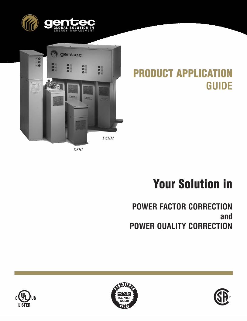
Power Factor Controller 12 or 6 stepNC12 or N6/N12 Models
N6/N12 NC12
(Communication capability)
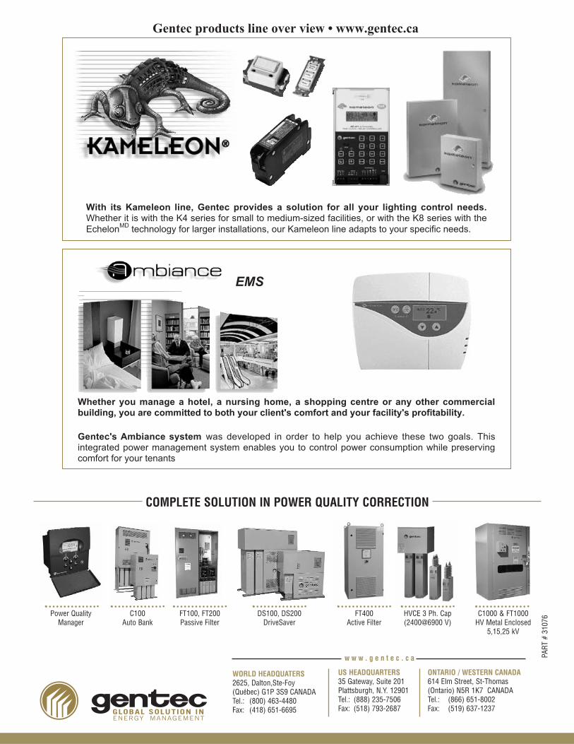
Gentec products line over view • www.gentec.ca
EMS
With its Kameleon line, Gentec provides a solution for all your lighting control needs.Whether it is with the K4 series for small to medium-sized facilities, or with the K8 series with theEchelonMD technology for larger installations, our Kameleon line adapts to your specific needs.
Whether you manage a hotel, a nursing home, a shopping centre or any other commercialbuilding, you are committed to both your client's comfort and your facility's profitability.
Gentec's Ambiance system was developed in order to help you achieve these two goals. Thisintegrated power management system enables you to control power consumption while preservingcomfort for your tenants
Power QualityManager
C100Auto Bank
FT100, FT200Passive Filter
DS100, DS200DriveSaver
FT400Active Filter
HVCE 3 Ph. Cap(2400@6900 V)
C1000 & FT1000HV Metal Enclosed
5,15,25 kV
COMPLETE SOLUTION IN POWER QUALITY CORRECTION
GLOBAL SOLUTION INENERGY MANAGEMENT
WORLD HEADQUATERS2625, Dalton,Ste-Foy(Québec) G1P 3S9 CANADATel.: (800) 463-4480Fax: (418) 651-6695
ONTARIO / WESTERN CANADA614 Elm Street, St-Thomas(Ontario) N5R 1K7 CANADATel.: (866) 651-8002Fax: (519) 637-1237
US HEADQUARTERS35 Gateway, Suite 201Plattsburgh, N.Y. 12901Tel.: (888) 235-7506Fax: (518) 793-2687
w w w . g e n t e c . c a PART
# 31
076