Embed Size (px)
Citation preview
Solar pump stations
NA28237.03
278-279 series
Function
Solar pump stations are used on the primary circuit of solar thermal water heating systems to control the temperature of the hot water storage. The pump inside the unit is activated by the signal from a differential temperature controller. The unit contains the functional and safety devices for optimum circuit control. They are available with both supply and return connection or with return connection only.The iSolar™ PLUS temperature differential controller, code 257260A (optional), is suitable for management and control of 10 pre-configured solar thermal system arrangements installed in an optional insulation jacket (code 278011) that mounts to the top of the pump station for a nice clean assembly and simplified wiring.
1
CONTENTS
Function
ImportantProduct rangeTechnical specifications
Characteristic components
InstallationFilling the system
Flushing the systemCommissioningDraining the system
1
2-3
4
5
6
Shut-off and check valvesAir separatorFlow meterCorrection for different density liquidsComplete closing and opening of the valve
7
Application diagrams 8
INSTALLATION AND COMMISSIONING MANUAL
© Copyright 2018 Caleffi
www.caleffi.com
These items are designed for use in closed systems. Do not use in plumbing applications. These items do not meet the low-lead plumbing standards of U.S. and Canada.
IMPORTANT
The following instructions must be read and understood before installing, commissioning and servicing the circulation unit.
The safety symbol is used in this manual to draw attention to safety instructions. The meaning of this symbol is as follows: CAUTION! YOUR SAFETY IS INVOLVED. FAILURE IN FOLLOWING THESE INSTRUCTIONS MAY RESULT IN INJURY.
- The solar pump station must be installed by a qualified technician in compliance with relevant national and/or localregulations.
- Install, commission and service the solar pump station correctly in accordance with the instructions given in thismanual to avoid malfunction and user endangerment.
- All connection fittings must be watertight.
- When making the hydraulic connections ensure that threads are not mechanically overstressed. Over time, excessivestress may cause breakage with water leaks, property damage and/or personal injury.
- Water temperatures higher than 120°F (50°C) may cause serious scalding.
- During installation, commissioning and servicing take the necessary precautions to prevent injury to persons causedby high temperatures.
CAUTION: Risk of electric shock. Discount the electric supply before carrying out any work. Failure in following these instructions may result in injury of persons or damage to property.
2
Product range
Code 278751A Single-line solar pump station with 3 speed pump, return connection and flow meter scale 2 to 8 gpm.........connection 3/4” female
Code 278751 Single-line solar pump station without pump, return connection and flow meter scale 2 to 8 gpm..................connection 3/4” female
Code 279051A Dual-line solar pump station with 3 speed pump, supply and return connections, flow meter scale 2 to 8 gpm.....................................................................................................................................................................connections 3/4” female
Code 279051 Dual-line solar pump station without pump, supply and return connections, flow meter scale 2 to 8 gpm.....................................................................................................................................................................connections 3/4” female
Code 278951A Single-line solar pump station for drainback with 3 speed pump, return connection and flow meter scale 2 to 8 gpm.....................................................................................................................................................................connections 3/4” female
WARNING: This product can expose you to chemicals including lead, which is known to the State of California to cause cancer and birth defects or other reproductive harm. For more information go to www.P65Warnings.ca.gov.
Technical specification
MaterialsShut-off valve body: brassCheck valve: brassTemperature gauge: steel/aluminum
Air SeparatorBody: brass
Body: brass Sealing gaskets: EPDMO-Ring seal elements: EPDM
Flow meterBody: Transparent level gauge: Flow indicator: Hydraulic seals:
Insulation Material: Average thickness: 3/4 inch (20 mm)Density: 2.8 lb/ft³ (45 kg/mWorking temperature range: 23 - 250°F (-5–120°C)Thermal conductivity: 0.263 BTU·in/hr·ft²·°F 0.037 W/(m·K)
at 50°Reaction to fire (UL94): class HBF
3
PerformanceSuitable fluids: water, glycol solutionMax. percentage of glycol: 50%Maximum working temperature:
air separator side supply: 320°F (160°C)pump side return: 230°F (110°C)
Max. working pressure: 145 psi (10 bar)Safety relief valve working temperature range: -20 to 320°F (-30–160°C)Safety relief valve setting: 90 psi (6 bar)Check valve min. opening pressure (Dp): 1/4 psi (2 kPa)Shut-off and check valves working temperature range:
-20 to 320°F (-30–160°C)Flow meter working temperature range: 15 to 230°F (-10–110°C)Flow rate adjustment range: 2 to 8 gpmFlow rate indicator accuracy: ±10%Pressure gauge scale: 0 to 145 psi (0–10 bar)Temperature gauge scale: 32 to 320°F (0–160°C)Connections: 3/4” female straight threadHose connection: 3/4” MFill/drain connections: with hose connection 9/16" OD (15 mm)
Pump model Wilo Star S-21Body: cast iron Electric supply: 115 V 60 HzMax. pressure: 140 psi (10 bar)Max. liquid temperature: 230°F (110°C)Min. liquid temperature: 14°F (-10°C)Max. current: 0.97 AMax. power consumption: 110 WProtection class: CSA enclosure 2Agency approval: cULus
Flow range: 0 to 18 gpm (0 to 1.1 l/s)Head range: 0 to 21 ft (0 to 6.4 m)
Pump model UP-100 DrainbackBody: cast iron GG 15/20Electric supply: 115 V 60 HzMax. pressure: 150 psi (10 bar) Max. liquid temperature: 205°F (96°C)Min. liquid temperature: 36°F (2°C)Max. current: 1.1 AMax. power consumption: 135 WAgency approval: cULus
Flow range: 0 to 8.4 gpm (0 to 0.5 l/s)Head range: 0 to 36 ft (0 to 11.0 m)
NOTE: pump data per manufacturer technical specifications.
2

54
Characteristic components
1) Circulation pump2) Safety relief valve3) Fill/drain valve with control lever4) Instrument holder fitting with pressure gauge5) Flow meter6) Air separator with air vent and shut-off valve with check valve7) Supply temperature gauge8) Return temperature gauge9) Pre-formed shell insulation10) Shut-off ball valve with check valve with temperature gauge
holder knob11) Connection kit for expansion tank (purchase separately)12) Hose connection13) Mounting bracket
101310
7
9
12
12
1
2
3
4
11
5
8
6
10
9
16
12
1
2
3
4
11
5
8
13
Dual
Single
54
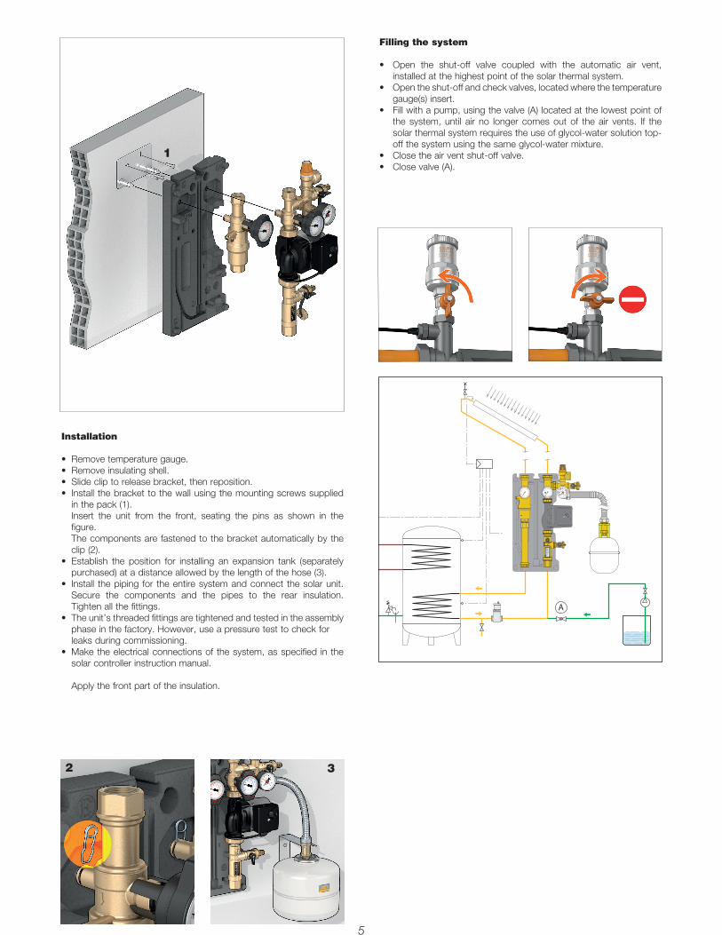
Installation
• Removetemperaturegauge.• Removeinsulatingshell.• Slidecliptoreleasebracket,thenreposition.• Installthebrackettothewallusingthemountingscrewssupplied
in the pack (1).Insert the unit from the front, seating the pins as shown in thefigure.The components are fastened to the bracket automatically by theclip (2).
• Establish the position for installing an expansion tank (separatelypurchased) at a distance allowed by the length of the hose (3).
• Install thepiping for theentiresystemandconnect thesolarunit.Secure the components and the pipes to the rear insulation.Tighten all the fittings.
• Theunit’sthreadedfittingsaretightenedandtestedintheassemblyphase in the factory. However, use a pressure test to check forleaks during commissioning.
• Maketheelectricalconnectionsofthesystem,asspecified inthesolar controller instruction manual.
Apply the front part of the insulation.
Filling the system
• Open the shut-off valve coupled with the automatic air vent,installed at the highest point of the solar thermal system.
• Opentheshut-offandcheckvalves,locatedwherethetemperaturegauge(s) insert.
• Fillwithapump,usingthevalve(A)locatedatthelowestpointofthe system, until air no longer comes out of the air vents. If thesolar thermal system requires the use of glycol-water solution top-off the system using the same glycol-water mixture.
• Closetheairventshut-offvalve.• Closevalve(A).
A
1
2 3
Commissioning
• Closetheflowmeterfill/drainvalve(1)andincreasepressureinthesystemtothemaximumdesignpressure,145psi(10bar),usingtheexternalfilling pump connected to the safety unit fill/drain cock. When this pressure is reached (2), close the safety unit fill/drain valve using the control lever.
• Openthevalvesunderthetemperaturegauges(3)andswitchonthesolarcirculationunitpump.• Allowthewatertocirculateforawhileandthencheckforleaks.• Re-opentheairventinstalledatthehighestpointofthesolarthermalsystemandrepeattheairpurgingprocedure,brieflyactivatingthecirculation
pump.• Restorethedesiredworkingpressurewiththefillingpump.• Theflowrateofthesystemcanbevariedusingtheflowmeter(4).Thismodulationisperformedbytheballvalvewithwhichitisequipped(see
respective characteristics). Follow the solar panel manufacturer's flow rate recommendations when setting the flow rate.• Afterthefirstfewoperatinghours,thesolarthermalsystemmustbepurgedofexcessairagain,bothinthehighestpointandontheairseparator
(if equipped). Once the air is purged, check system pressure and if necessary restore to the desired working pressure.
Draining the system
• Drainingisnecessaryifthesystemhasbeenfilledwithwateronlyandthereisariskoffrost.• Opentheshut-offandcheckvalves(underthetemperaturegauges),turningthem45°.Opentheairventsatthehighestpoint.• Openthedrainvalveatthelowestpointofthesystem.
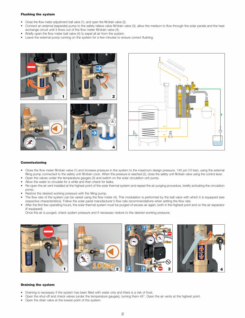
Flushing the system
• Close the flow meter adjustment ball valve (1). and open the fill/drain valve (2).• Connectanexternal(separate)pumptothesafetyrelievevalvefill/drainvalve(3),allowthemediumtoflowthroughthesolarpanelsandtheheat
exchange circuit until it flows out of the flow meter fill/drain valve (4).• Brieflyopentheflowmeterballvalve(4)toexpelallairfromthesystem.• Leavetheexternalpumprunningonthesystemforafewminutestoensurecorrectflushing.
1
6 7
1
2
2 3 4
3 4
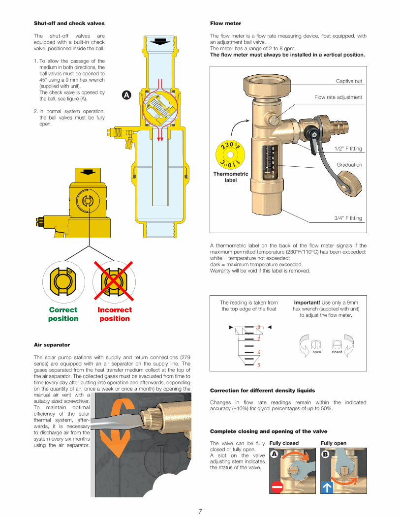
Shut-off and check valves
The shut-off valves are equipped with a built-in check valve, positioned inside the ball.
1. To allow the passage of themedium in both directions, theball valves must be opened to45° using a 9 mm hex wrench(supplied with unit). The check valve is opened bythe ball, see figure (A).
2. In normal system operation,the ball valves must be fullyopen.
A
Complete closing and opening of the valve
The valve can be fully closed or fully open.A slot on the valve adjusting stem indicates the status of the valve.
Correction for different density liquids
Changes in flow rate readings remain within the indicated accuracy (±10%) for glycol percentages of up to 50%.
Fully closed Fully open
6 7
Captive nut
Flow rate adjustment
1/2” F fitting
Graduation
3/4” F fitting
Flow meter
The flow meter is a flow rate measuring device, float equipped, with an adjustment ball valve. The meter has a range of 2 to 8 gpm.The flow meter must always be installed in a vertical position.
A thermometric label on the back of the flow meter signals if the maximum permitted temperature (230°F/110°C) has been exceeded: white = temperature not exceeded;dark = maximum temperature exceeded.Warranty will be void if this label is removed.
The reading is taken from the top edge of the float
Important! Use only a 9mm hex wrench (supplied with unit)
to adjust the flow meter.
8
7
6
5
◀◀
open closed
230 F110C
Thermometric label
A B
Correct position
Incorrect position
Air separator
The solar pump stations with supply and return connections (279 series) are equipped with an air separator on the supply line. The gases separated from the heat transfer medium collect at the top of the air separator. The collected gases must be evacuated from time to time (every day after putting into operation and afterwards, depending on the quantity of air, once a week or once a month) by opening the manual air vent with a suitably sized screwdriver.To maintain optimal efficiency of the solar thermal system, after-wards, it is necessary to discharge air from the system every six months using the air separator.

Application diagrams
Shut-o� valve
Pump
Air vent
Expansion tank
Temperature gauge
Safety valve
Automatic�lling
2
Shut-o� valve
Pump
Air vent
Expansion tank
Temperature gauge
Safety valve
Automatic�lling
2
87-24-18