Embed Size (px)
Citation preview

8/26/2009
1
CALEFFI. NATURAL SOLUTIONS.47 years of growth.
Website Technical Trainer
Caleffi North America Inc.Caleffi North America Inc.414414--238238--23602360www.caleffi.uswww.caleffi.us
2

8/26/2009
2
Zoning with CaleffiFeaturing Z-one Zone Valve
3
Webinar Outline• INTRODUCE CALEFFI ZONE VALVE PRODUCTS
Quick Review of each styleCompare operating characteristics
• IN-DEPTH ANALYSISZ-one Series
MOST COMMON REASONS FOR TECH CALLS• Q & A
4

8/26/2009
3
Industry Trend – Returning to Zone Valves
From idronics #5, page 26
5
Caleffi Zone Valve Products
Z-one
Thermo-Electric Zone Valve:
676 series
Motorized Ball Valves:
644 Series
6
8/26/2009
4
Caleffi Zone Valve Products24 VAC Supply 656 Series Z-one 644 SeriesInrush Current Draw (mA) < 1000 300 170
Inrush VA 19 7 4
Holding Current (mA) 140 300 0
Holding Watts 3 5 0g
Holding VA 3 7 0
Notes: Time required to reach holding current is
approx. 2 minutes, spring return
120-180 sec full stroke
Steady current draw, spring return
< 60 sec full stroke OPEN< 10 sec full stroke
CLOSED
Motor drives for 40 seconds then power is
dropped by internal switch, requires power in
both directions
Size/Connection/Cv /Close off PSI
½” Sweat 4 Cv / 20 psi¾” Sweat 4 Cv / 20 psi1” Sweat 4 Cv / 20 psi
½” 1.0 Cv / 75 psi½” & ¾” 2.5 Cv / 50 psi½” & ¾” 3.5 Cv / 30 psi¾” & 1” 5.0 Cv / 25 psi
¾”, 1” & 1-1/4” 7.5 Cv / 20 Inv Flare (1.0, 2.5, 3.5 Cv)
SAE Flare (½” 3 5 Cv)
½”, ¾”, 1” 13 Cv for 2-way½”, ¾”, 1” 4.5 Cv for 3-way diverting½”, ¾”, 1” 12 Cv / 1.5 Cvfor bypass portAll styles 150 psi close-offAll styles available withSAE Flare (½ 3.5 Cv)
NPT (½”, ¾”, 1”-7.5 Cv)Sweat (½”, ¾”, 1”, 1-1/4”)
All styles available with Sweat or NPT connections
2-way only 2-way3-way (divert or mix)
2-way3-way (divert or mix)
3-way (bypass)
Max Water Temp. 200 F 240 F 230 F
Actuator Thermo-Electric Hysteresis Motor Permanent Magnet Motor
Valve flow control member Disk Paddle Ball
Max Static Pressure 150 psi 300 psi 150 psi7
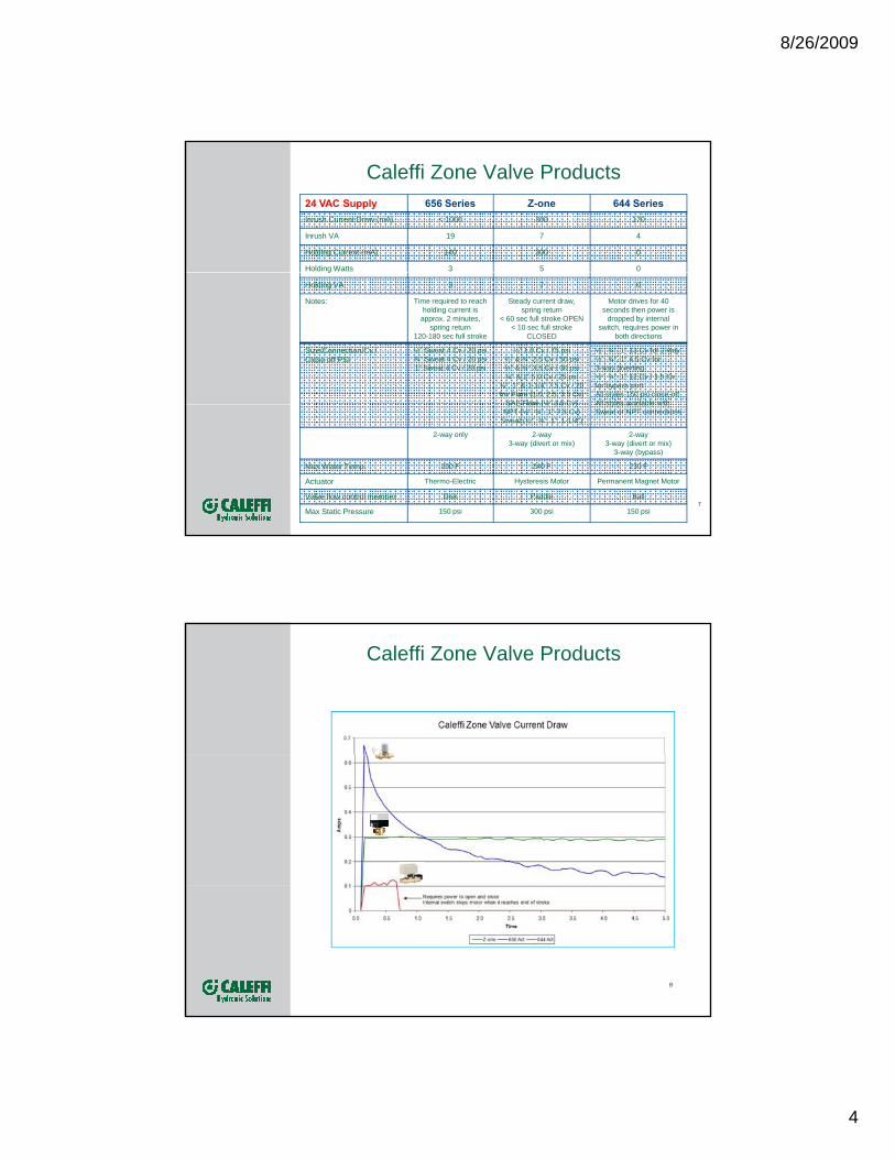
Caleffi Zone Valve Products
’ fMike: didn’t you find out this was 5 and not 6.5?
8

8/26/2009
5
Z-oneIn-depth Analysis
Actuator2. Motor: 7 VA, 5 W3. Poly Carbonate
Cover and Base
1. Aluminum Motor Plate
10. 20:1 Reduction Gear
9a. Bronze Bushing9b. Case hardened 12L14 Steel Pinion 9c. Extra Thick Sector Gear
5. Large push button release
4. Manual Opening Lever Train
8. Stainless Steel Torsion Spring
12. Sealed End Switch
11. Lost Motion design7. Same body for NO and NC actuators
6. Terminal Block option
9
Z-oneIn-depth Analysis
Actuator2. Motor: 7 VA, 5 W3. Poly Carbonate
Cover and Base
1. Aluminum Motor Plate
10

8/26/2009
6
Aluminum Casing – No corrosion from chilled water condensation. Aids in heat dissipation. Others use plated steel.
Inside the Z-one Actuator
Reliable Motor – Paired with the lost motion gear, twice the gear ratio is achieved versus competitive units. Result is high close off pressures and less stress on the motor for longer life.
Polycarbonate Cover – High temp rated and durable.
11
Z-oneIn-depth Analysis
Actuator
5. Large push button release
4. Manual Opening Lever
6. Terminal Block option
12

8/26/2009
7
Z151000 Screw Terminal Connection
13
Z-oneIn-depth Analysis
Actuator
10. 20:1 Reduction Gear
9a. Bronze Bushing9b. Case hardened 12L14 Steel Pinion 9c. Extra Thick Sector Gear
Train
8. Stainless Steel Torsion Spring
7. Same body for NO and NC actuators
14

8/26/2009
8
Inside the Z-one Actuator
Return Spring - when power is removed, torque from return spring closes valve.
Pinion Gear– has a unique “lost motion” design.
pinion
pinion
pinion
15
Inside the Z-one Actuator
pinion
12L14 case hardened steel pinion
Next Slide16

8/26/2009
9
Inside the Z-one Actuator
All parts inside the Z-one actuator are corrosion resistant.
pinion
Bronze Bushing
17
Inside the Z-one Actuator
Spring is wound until correct torque value i h dpinionis reached
Erie & HW’s spring position is fixed making them vulnerable to manufacturing tolerances
18

8/26/2009
10
Inside the Z-one Actuator
Large gear face spreads load evenly
i ipinionacross motor pinion(twice the thickness of competitive zone valves)
Honeywell sector gear is thin and concentrates stress on motor pinion
(See HW thin gear video)19
Z-oneIn-depth Analysis
Actuator
11. Lost Motion design
20

8/26/2009
11
Innovative motion - Unlike other brands where motor drives a sector gear directly, the Z-one motor drives an extra “lost motion” gear for more torque and smoother, higher close-off.
Inside the Z-one Actuator
sector
cogidler
Durability Caleffi’s exclusive “lost motion” gear
(underside view of lost motion gear)
groovegroovepinion
Durability – Caleffi’s exclusive “lost motion” gear protects the motor. How? As the valve seats during spring return, the lost motion gear “coasts” thus preventing an impact load which can heavily stress gear teeth and bearings – a common cause of failure in competitive units.
(See Lost Motion Videos)21
Z-oneIn-depth Analysis
Actuator
12. Sealed End Switch
22

8/26/2009
12
OVERVIEW OF NEW END SWITCH DESIGN
The 24 Volt Z-one actuator end switches have been redesigned and are now standardized
The change is not externally noticeable.
Internally, however, you’ll see that the previous switch is white in color.
The new design is black.
23
Old design 24 V modelsCurrent for other
VoltagesNew design 24 V models:
Z111000Z151000
OVERVIEW OF NEW END SWITCH DESIGNPrior design
New design
24

8/26/2009
13
OVERVIEW OF NEW END SWITCH DESIGN
Utilizing reed switch technology, Caleffi has developed an innovative sealed end switch design- PATENT PENDING – that will not be susceptible to the effect of environmental airborne contamination, and can significantly extend operating life.
Commonly used for years in automotive applications, the reed switch y y pp ,features electrical contacts that are sealed from potential exposure to air-borne contaminants.
The hermetically-sealed reed switch contacts open and close by way of a magnet imbedded in the sector gear.
This switch has been specifically designed for switching 24 V relays, boiler contacts (TT) and DDC systems.
It has exceptionally long life, having been tested to over 1 million cycles without failure.
25
.
Magnetism attracts reeds, closing normally open contacts.
Normally
The reed switch is actuated by the field from a magnet coupled to the actuator sector gear.
There are no mechanical cams as with traditional designs, offering fewer parts susceptible to wearing out.
OVERVIEW OF NEW END SWITCH DESIGN
Normally Closed
Position-Switch
contacts open
Open position-Switch
26
contacts now closed
Magnet
Sector Gear
Enclosed Reed Switch
(See reed switch video)

8/26/2009
14
OVERVIEW OF NEW END SWITCH DESIGN
Extensive life testing has been completed and all 24 V actuators are now shipping with this feature.
The instruction sheet and recently released technical brochure (01115-09 NA) have been revised accordinglyhave been revised accordingly.
27
OVERVIEW OF THE PRIOR END SWITCH DESIGN
Zone Valve manufacturers typically use micro switches for their end switch design.
Micro switches incorporate silver contacts that are susceptible to residue build up due to air borne contaminants such as sulfurresidue build up due to air borne contaminants such as sulfur.
28

8/26/2009
15
What’s wrong with a micro switch in low voltage applications?
Zone Valve Manufacturers typically use commercially-available micro switches for their end switch design.
Micro switches incorporate silver contacts, are typically open to the atmosphere, and therefore require sufficient current to wipe the contacts clean during normal q p goperation.
This is especially true with the low 24 VAC powered actuators.If the system does not have enough current draw the switch contacts are susceptible to
residue buildup due to airborne contaminants such as sulfur from boiler combustion. This increases the resistance disabling the switch to close.
Because of this, typically the operating life for these switches can be shorter than expected for most contractors and end users, and this depends on their location and operating frequency.
29
What’s wrong with a micro switch in low voltage applications?
Returned Caleffi micro switchshowing the accumulatedresidue leading to failure
30

8/26/2009
16
Current Draw
Minimum current draw for each switch is to ensure enough power to clean off accumulating residue from the environmental surroundings.
An example of this is sulfur from boiler combustion attracting to and coating the silver contacts in the switch.g
Added sources of sulfur are floor wax, other household products, and Chinese manufactured Drywall.
31
Current Draw
Zone valve manufacturers now specify and require a minimum current draw for each switch-Erie- 101mA
32

8/26/2009
17
Additional Benefit of the Reed Switch Design
In addition to the contacts being sealed from outside and effects of airborne contaminants-
The reed switch design offers no required minimum current load for more cost effective system designing
Most zoning panels source an end switch signal in the range of 40 – 70 mA per zone, g p g g pallowing only one zone valve end switch. Caleffi zone valves now offer the ability to install multiple end switches connected in parallel into the zoning panel.
33
Additional Benefit of the Reed Switch Design
100 mA(Boiler current draw)
Following Erie’s spec, with 100 mA limit only 1 should be installed. The wiping current reduces with each additional
(Boiler current draw)
101 mA Erie
zone valve.
34

8/26/2009
18
Additional Benefit of the Reed Switch Design
For Caleffi’s Reed Switch-No limit to # of zone valves to install in parallel as there isno issue with wiring in parallel 100 mA
(Boiler current draw)
Z111000
Z111000
Z111000
Z111000
g p(Boiler current draw)
Z111000
Z111000
35
NEW END SWITCH DESIGN
Summary:
24V actuators use a patent pending sealed reed switch for the end switch:-Hermetically sealed from potential exposure to air-born contaminants
extending operating life-Requires no minimum current load allowing an unlimited number of 24V-Requires no minimum current load allowing an unlimited number of 24V
actuator end switches in parallel to one zoning panel or thermostat.
36

8/26/2009
19
Z-oneIn-depth Analysis
Actuator2. Motor: 7 VA, 5 W3. Poly Carbonate
Cover and Base
1. Aluminum Motor Plate
10. 20:1 Reduction Gear
9a. Bronze Bushing9b. Case hardened 12L14 Steel Pinion 9c. Extra Thick Sector Gear
5. Large push button release
4. Manual Opening Lever Train
8. Stainless Steel Torsion Spring
12. Sealed End Switch
11. Lost Motion design7. Same body for NO and NC actuators
6. Terminal Block option
37
Z-oneIn-depth Analysis
ActuatorCaleffi Advantage! BENEFIT
1. Aluminum Motor Plate vs. competitors plated steel
No corrosion from chilled water condensation. Aids in heat dissipation.
2. Hansen Motor . 7 VA current draw and 5 W power consumption.
Made in USA. Allows up to 5 valves per standard 40 VA transformer.
3. High Strength Poly Carbonate Cover/Base Won’t Corrode. High temp rated and durable.
4. Stainless Steel Manual Open Lever, travels through nearly all of the actuator stroke
Won’t corrode. Latch is easy to move and makes manual operation easy. Overridden when power restored. Good travel indicator.
5. Patented Large Push Button Design-with stainless steel return spring
No screws or linkages. Makes assembly to valve body and removal easy.
6. Terminal Block Design Easy and clean connection option (designed for the Z-one, wiring directions molded in to case)
7. Same valve body for Normally Open and Normally Closed actuators
Easy stocking with fewer items, easy field change out
8. Stainless Steel Torsion Spring wound to torque Provides consistent torquevalue and not to position
9. a. Bronze Bushingb. Case hardened 12L14 Steel Pinionc. Extra Thick Sector Gear
a,b.Solid, rugged design providing long service life; common for heavy duty gearingc. Better motor drive engagement and no stripped gears
10. Large Reduction Gear Train(20:1) vs. competitors (10:1 or 12:1)
Less stress on motor for longer life. More torque, higher close off
11 Lost Motion design Protects gears and motor, eliminates impact (see videos)
12. Sealed Reed Switch/magnet, patent pending No cams to align or wear. Protected from harsh environments. (see video)
38

8/26/2009
20
Z-oneIn-depth Analysis
Valve Body
19. Stainless Valve Stem and rubber insert
18. Forged brass body 300 PSI,32 – 240º F, 15 PSI steam
13. EPDM paddle and o-rings vs. BUNA-N
15. Large Valve Cavity16. Hex Nut
14. Paddle design vs. competitors ball17. One body for 32 – 240º F water
and 15 PSI steam
39
Z-oneIn-depth Analysis
Valve BodyCaleffi Advantage! BENEFIT
13. Peroxide cured EPDM Paddle and o-rings, vs. competitors Buna N
For high temperature and oxygen electrolysis resistance from high boiler feed and open system applications
14. Paddle design vs. Ball Same sealing surface over the life of the product. Rubber balls rotate and must seal over previous seat impressions.
15. Large Valve Cavity and Longer Stroke(45° versus Erie’s 22° stroke)
Quieter flow and prevention of water hammer. Slows the flow of water down earlier and for a longer distance.
16. Hex nut Easy clean out and easy replacement of stem/plug assembly.
17. One body for water (32 -240°F) and 15 psi steam
Easy stocking with fewer items, less chance for error when selecting.
18. Forged brass body, 300 psi static pressure rating
For superior strength and durability
19. Stainless Steel Valve Stem and Rubber Insert
Better corrosion protection versus nickel plated brass used by competitors. (Beryllium Copper rivet holds paddle to stem.)
40

8/26/2009
21
Some Common Technical CallsQ: So, just how does the “Lost Motion” feature work in the Z-one?A: In order to achieve high close off pressures and longer life in a zone valve,
Caleffi has developed a new drive mechanism in their zone valve compared to tradition zone valve designs. Traditional designs typically use a synchronous motor which drives a gear. That gear is spring loaded and it typically drives a stem and some sort of sealing member When power istypically drives a stem and some sort of sealing member. When power is supplied to the motor, the motor drives the gear which opens the valve. When power is dropped from the motor, the spring (either torsion or extension) is used to close the valve. One of the major disadvantages with this type of system occurs during the spring closing. Because the return spring is located on the sector gear, the gear is “back driving” the pinion. Whenever a gear is driving a pinion the efficiency is very low, especially when large ratios are used like most zone valves. In the Caleffi Z-one valve, a different approach has been taken. An additional gear cluster has been added to the drive. This additional gear cluster does two things, it allows for a higher gear reduction and it allows the torsion spring to be located on the pinion which is driving the final sector gear. This means that during opening or closing of the valve, the pinion is always driving the sector gear allowing for a more efficient transfer of torque to the stem.
• Another problem associated with traditional zone valve designs is the impact that occurs on the sector gear and motor when the sealing member hits the seat. When power is dropped to the motor, the return spring puts a force on the sector gear to “back drive” the motor. The motor gearbox contains many small gears and when they start to spin they build up inertia. All of this momentum comes to an abrupt stop when the sealing member hits the seat. The sector gear and motor then see a large impact force from this which causes the sector gear or the motor gears to fail. The Caleffi Z-one valve uses a unique approach to eliminate or reduce this impact considerably. The pinion which is driven by the sector gear has a tab protruding upward.
41
Some Common Technical Calls• Answer Continued:
Another problem associated with traditional zone valve designs is the impact that occurs on the sector gear and motor when the sealing member hits the seat. When power is dropped to the motor, the return spring puts a force on the sector gear to “back drive” the motor. The motor gearbox contains many small gears and when they start to spin they build up inertia. All of this g y p y pmomentum comes to an abrupt stop when the sealing member hits the seat. The sector gear and motor then see a large impact force from this which causes the sector gear or the motor gears to fail. The Caleffi Z-one valve uses a unique approach to eliminate or reduce this impact considerably. The pinion which is driven by the sector gear has a tab protruding upward.
This tab engages with another tab on the bottom side of the mating gear that the motor drives. This allows the gear to have “lost motion” travel. In other words, the synchronous motor is allowed to disengage from the rest of the gearing when the paddle strikes the seat allowing the motor to coast to a stop. This prevents the impact loading and extends the life of the actuator.
42

8/26/2009
22
Some Common Technical CallsQ: Is the brass used in the Z-one valve bodies and wetted rubber parts also
compatible for potable water? A: Caleffi does not have NSF 61 approval but we do have customers that use
the valve in potable water situations. Just state that we do not have NSF 61 approval and let them decide.
Q D th f t h NSF 61 l?Q: Does any other manufacturer have NSF 61 approval?A: Not that Caleffi is aware of as of August 2009.
Q: Do you have sizing charts to size a zone valve for steam?A: No. These zone valves, however, can control up to a maximum 15 psi
saturated steam. The maximum steam flow can be roughly calculated knowing the Cv of the valve with the formula-Steam flow in lb/hr= Cv x 2.1 x Sq Root (max press drop x (P1 + P2)). And, then you can get the EDR (Equivalent Direct Radiation) value = lb/hr /(.24).
Q: Do you have a repair kit for the inner valve and stem?A: Yes, PN 69293A. It is not published but is available for that rare special
request.
Q: Will a Caleffi Z-one actuator work on an Erie valve?A: No.
43
Some Common Technical CallsQ: What is Cv?A: Cv is a valve sizing coefficient determined experimentally for each style and
size of valve, using water at standard conditions as the test fluid. Cv is numerically equal to the number of US gallons of water at 60°F that will flow through the valve in one minute when the pressure differential across the valve is 1 psi Cv varies with both size and style of valve but provides anvalve is 1 psi. Cv varies with both size and style of valve, but provides an index for comparing liquid capacities of different valves under a standard set of conditions.Flow (gpm) = Cv x SQRT(∆P / G ) where G= specific gravity of fluid (water at 60°F = 1.0) or,Cv = Q x SQRT (G / ∆P ) where Q = Flow rate in gpm
44

8/26/2009
23
Some Common Technical CallsQ: Do you have a Caleffi Cross Reference to Competitors?A: YES, here’s page 1 of 5. It is included in Resource materials included with
this presentation or by calling Caleffi.
45
Some Common Technical CallsQ: I expect the Z-one must be 'idiot proof' when installing the actuator on a
valve body.. that is, there's no chance that it could be 'backwards' in that when it's called to drive open that the valve paddle is already at the end stop and the actuator is over torque-ing thinking it's driving open?
A: The actuators are pretty much idiot proof. They can only be installed one way and they self limit the stroke The only thing that can be doneway and they self limit the stroke. The only thing that can be done incorrectly is to install a normally open actuator on a 3-way valve body, that’s a no-no due to the lower torque output of the NO actuator during spring opening.In addition, the motor in the Z-one valve can’t “over torque” itself or draw more current when loaded. If 24 VAC is applied, it can never deliver more torque, even when it is stalled. The motor is unique in that it is designed to be stalled indefinitely.
Q: What is current draw of the Z-one Zone valves?A: The current draw for the Z-one by actuator voltage:
24 VAC = 300 mA120 VAC = 55 mA120 VAC = 55 mA208 VAC = 30 mA230 VAC = 25 mA277 VAC = 20 mA
46

8/26/2009
24
47
+1 414.238.2360
CALEFFI North America Inc.
3883 West Milwaukee Road Milwaukee, WI 53208Tel. +1 414-238-2360
Fax +1 414-4238-2366
48

11/19/2009
1
CALEFFI. NATURAL SOLUTIONS.47 years of growth.
WebsiteTechnicalTrainer
Caleffi North America Inc.Caleffi North America Inc.414414--238238--23602360www.caleffi.uswww.caleffi.us
2

11/19/2009
2
Zoning with CaleffiPart 2
3
Webinar Outline• INTRODUCE CALEFFI ZONE VALVE PRODUCTS
Quick Review of each styleCompare operating characteristics
• IN-DEPTH ANALYSIS644 High Flow High Close-off Motorized Ball Valves656 Thermo-electric Actuators
-for Radiant Manifold circuit control-676 Zone Valve
519 Differential Pressure Bypass Valves
MOST COMMON REASONS FOR TECH CALLS• Q & A
4

11/19/2009
3
Caleffi Zone Valve Products
Z-one
519 Series Differential Pressure Bypass Valves
Thermo-Electric Zone Valve: 676 series 644 Series Motorized Ball Valves
5
Caleffi Zone Valve Products24 VAC Supply 656 Series Z-one 644 SeriesInrush Current Draw (mA) < 1000 300 170
Inrush VA 19 7 4
Holding Current (mA) 140 300 0
Holding Watts 3 5 0g
Holding VA 3 7 0
Notes: Time required to reach holding current is
approx. 2 minutes, spring return
120-180 sec full stroke
Steady current draw, spring return
< 60 sec full stroke OPEN< 10 sec full stroke
CLOSED
Motor drives for 40 seconds then power is
dropped by internal switch, requires power in
both directions (relay)
Size/Connection/Cv /Close off PSI
½” Sweat 4 Cv / 20 psi¾” Sweat 4 Cv / 20 psi1” Sweat 4 Cv / 20 psi
½” 1.0 Cv / 75 psi½” & ¾” 2.5 Cv / 50 psi½” & ¾” 3.5 Cv / 30 psi¾” & 1” 5.0 Cv / 25 psi
¾”, 1” & 1-1/4” 7.5 Cv / 20 Inv Flare (1.0, 2.5, 3.5 Cv)
SAE Flare (½” 3 5 Cv)
½”, ¾”, 1” 13 Cv for 2-way½”, ¾”, 1” 4.5 Cv for 3-way diverting½”, ¾”, 1” 12 Cv / 2.1 Cvfor bypass portAll styles 150 psi close-offAll styles available withSAE Flare (½ 3.5 Cv)
NPT (½”, ¾”, 1”-7.5 Cv)Sweat (½”, ¾”, 1”, 1-1/4”)
All styles available with Sweat or NPT connections
2-way only 2-way3-way (divert or mix)
2-way3-way (divert or mix)
3-way (bypass)
Max Water Temp. 200 F 240 F 230 F
Actuator Thermo-Electric/Wax Motor Hysteresis Motor Permanent Magnet Motor
Valve flow control member Disk Paddle Ball
Max Static Pressure 150 psi 300 psi 150 psi
6

11/19/2009
4
Caleffi Zone Valve Products
’ fMike: didn’t you find out this was 5 and not 6.5?
7
High Flow, High Close-off Zone Valves
644 Series Motorized Ball Valves with 3-wire Control
6442 series 2-way
6443 series 3-way…3BY (Bypass)… (Diverting)
644004 replacement actuator
8

11/19/2009
5
High Flow, High Close-off Zone Valves
644 Series Motorized Ball Valves with 3-wire Control
Easy to Install or Remove Actuator
Simply push actuator on(no button or lever)
Squeeze the release lever and lift actuator off valve body(no screws or linkage)
9
Designed for High Flow & High Close-off
Extra Thick Sector Gear - for better motor drive
engagement and no t i d
More Valves per Transformer - High electrical efficiency 24V allows for 9 valves on standard 40 VA transformer
644 Series Zone Valves
Forged brass body -
EPDM O-rings - for high temperature and oxygen electrolysis resistance from high boiler feed and open system applications
Squeeze release lever -makes assembly to valve
body and removal easy
stripped gearsstandard 40 VA transformer
Internal Switch- shuts of motor at end of travel
Large 13 Cv full port ball -higher flow with little pressure drop and high 150 psi close-off
Forged brass body for superior
strength and durability, 23 – 230ºF temperature
rating.
10
Integral O-rings-no gasket to loose or
hold onto during installation

11/19/2009
6
Connections Flow Coefficient Max. Close-off ∆P
644 Series Zone ValvesHigh Close-off per Cv
2-way NPT and Sweat
150 PSI
1/2“
13 Cv3/4“
1“
3-way NPT and Sweat Bypass
1/2“ 12 Cv-Straight Thru2.1 Cv-Bypass port3/4
11
1“
3-way NPT and Sweat Diverting/Mixing
1/2“
4.5 Cv Both Ports3/4
1“
644 Series Zone Valves
Zero leakage across the valve40 second stroke time both directionsOperates at very high differential pressures
Selling Features
Low pressure drop through the valveUnion connections for simple installs and removals
.
12
11/19/2009
7
644004 Actuator644 Series Zone Valves
ON/OFF (2 Position) Operating Mode:Can be used this way with a single electrical signal for opening or closing from 3-wire thermostat/timer-thermostat or an ordinary switch
MODULATING MODEThis actuator can be combined with any type of three-wire floating controller for outdoor reset on radiant systems. Not recommended for 2-way valves because the ball is not characterized.
AUXILIARY MICROSWITCHEquipped standard with a micro switch. Turns on for an average valve opening of 80%.
.
13
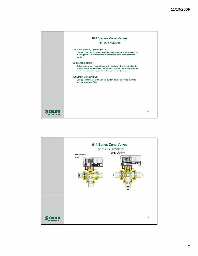
Bypass vs Diverting?644 Series Zone Valves
14

11/19/2009
8
Bypass vs Diverting?644 Series Zone Valves
The bypass valve has one inlet and two outlets
Cv for the bypass operation much lower than in“open” or normal operation.
When there is a call for heat, the valve is in normal 2.1 Cv,flow position, straight through with a 12 Cv
When no heat is called for, it closes off the port tothe fan coil and ‘bypasses’ flow, at a much lowerflow rate, 2.1 Cv, to keep the constant speedpump from dead heading
The diverting valve also has one inlet and twooutlets
The diverter has the same flow characteristics onthe two outlet ports
This valve can also be used for mixing with two inlet ports
No compromise on flow rate through either port
The key difference is the much lower Cv on the bypassing port to accommodate a special need for fan coil installations 15
Thermoelectric Zone Valve676 Series
Compact – for baseboards or in cabinets Optional Manual
T i T (656314)
Quiet – 24V thermoelectric with end switch (656114).
The max ambient temp is 120F for this thermo-electric actuator.
TwisTop (656314).
Spring Return –Normally Closed
Union connections in ½” , ¾” and 1” sweat and NPT
Forged brass body for superior strength and durability, 32 – 200º F temperature rating, 150 psi max working pressure

11/19/2009
9
Standard & TwisTop™ Actuators656314Manual TwisTop 24V with position indicator and end switch. Fits many competitive manifolds (check with factory)
656114Standard 24V with end switch. Fits many competitive manifolds (check with factory)
Manual TwisTop engages end switch and auto-returns when energized.
Green open indicator ring for easy viewing from any direction
17
•Heat Motor•24VAC power warms wax, expanding and forcing piston assembly upward allowing the spring-loaded shaft in either the manifold or in the 676 valve body to open the valve (1)•Very slow 1/8” movement: 2-3 minutes•Remains open as long as power is applied, 140 mAholding current, 2 to 4 watts.•When power is removed, the wax cools and contracts
656 TwisTop (optional)
656 Standard
contracts•The internal return spring assists in closing the valve•Both models have 36” wire lead connections
.
1 •The TwisTop opens with a twist when power is off and returns to Auto position automatically when
18
676
p ypower returns•Green ring indicates open actuator and can be seen from all sides•It is available for the 676 series zone valves, with and without microswitch
.

11/19/2009
10
19
Differential Pressure Bypass Valves519 Series
Lockable adjustment Adjustable from 2 to 10 psi always visible on neck (1 to 6 bar) differential pressure
519709A
NEW!
20
Fitting Sizes:¾” MNPT inlet with ¾” MNPT outlet - flow up to 9 GPMNEW: ¾” Sweat inlet AND outlet – flow up to 9 GPM
1” FNPT inlet with 1” Sweat or NPT outlet - flow up to 40 GPM
1 ¼” FNPT inlet with 1 ¼” Sweat or NPT outlet- flow up to 45 GPM
519599A
519502A

11/19/2009
11
Differential Pressure Bypass Valves
To limit differential pressure increase in systems using fixed-speed circulators
Adjustment:2 – 10 psi
21
Flow rates:¾” up to 9 gpm1” to 40 gpm1-1/4” to 45 gpm
Ensures Consistent Secondary Flow, Prevents “Dead-Heading” Pump & Minimizes Water Hammer
22

11/19/2009
12
Differential Pressure Bypass Valves
Setting Procedure:
a) With the hydronic system operating2 psi
a) With the hydronic system operating and all zone valves fully open (electrical, not manual), close the bypass valve by turning the control knob clockwise to stop at the maximum value (10 psi position).
b) Gradually open the valve with the control knob and use a thermometer or your hand to check on hot water flow.
c) As soon as you note a rise in
10 psi
23
temperature, turn the control knob closed one-half turn (clockwise) to stop flow.
d) Lock the knob in position with the locking screw.
Some Common Technical CallsQ: What is the difference between the 3 way bypass and the 3 way diverting? Could you give me an application example for both.A: Please refer to Tech Brochure 1131. The bypass valve has one inlet and two outlets and is designed specifically for the application on the 6th page lower diagram. And, notice, too that on the 4th page the flow characteristics show the Cv for the bypass operation much lower than in “open” or normalshow the Cv for the bypass operation much lower than in open or normal operation. This valve is installed, say, just before the fan coil. When there is a call for heat, the valve is in normal flow position, straight through with a 12 Cv. When no heat is called for, it closes off the port to the fan coil and ‘bypasses’ flow, at a much lower flow rate, 2.1 Cv, to keep the constant speed pump from dead heading. This is a standard, typical application. The valve’s piping orientation accommodates the piping scheme into the fan coil typically. The diverter has the same flow characteristics on the two outlet ports (or this valve can also be used for mixing with two inlet ports). The 7th page shows a typical application in solar systems where the flow is diverted for various purposes. There is no compromise on flow rate through either port. It can be confusing as one could attempt to use one for the other. The key really is the much lower Cv on the bypassing port to accommodate a special need for fan coil installations (or others like it).
24

11/19/2009
13
25
+1 414.238.2360
CALEFFI North America Inc.
3883 West Milwaukee Road Milwaukee, WI 53208Tel. +1 414-238-2360
Fax +1 414-4238-2366