Embed Size (px)
Citation preview
40.01
Contents
Accessories Page
D-Sub adaptor . . . . . . . . . . . . . . . . . . . . . . . . . . . . . . . . . . . . . . . . . . . . . . . 40.02
Han® Split Hood . . . . . . . . . . . . . . . . . . . . . . . . . . . . . . . . . . . . . . . . . . . . . . 40.04
Cable clamps for metric cable entries . . . . . . . . . . . . . . . . . . . . . . . . . . . . . . 40.06
Cable clamps for PG cable entries . . . . . . . . . . . . . . . . . . . . . . . . . . . . . . . . 40.08
Further Accessories . . . . . . . . . . . . . . . . . . . . . . . . . . . . . . . . . . . . . . . . . . . 40.11
Coding for Hoods/Housings and inserts . . . . . . . . . . . . . . . . . . . . . . . . . . . . 40.12
PE-Multiple ground connection . . . . . . . . . . . . . . . . . . . . . . . . . . . . . . . . . . 40.13
Cable clamp fitting . . . . . . . . . . . . . . . . . . . . . . . . . . . . . . . . . . . . . . . . . . . . 40.14
Docking frame . . . . . . . . . . . . . . . . . . . . . . . . . . . . . . . . . . . . . . . . . . . . . . . 40.15
Grip panel . . . . . . . . . . . . . . . . . . . . . . . . . . . . . . . . . . . . . . . . . . . . . . . . . . . 40.16
Ground terminal . . . . . . . . . . . . . . . . . . . . . . . . . . . . . . . . . . . . . . . . . . . . . . 40.18
Screws . . . . . . . . . . . . . . . . . . . . . . . . . . . . . . . . . . . . . . . . . . . . . . . . . . . . . 40.19
Locking levers . . . . . . . . . . . . . . . . . . . . . . . . . . . . . . . . . . . . . . . . . . . . . . . . 40.20
Gaskets, seals . . . . . . . . . . . . . . . . . . . . . . . . . . . . . . . . . . . . . . . . . . . . . . . 40.21
Accessories
40.02
Accessories
D-Sub Han AIdentification size housing size Part No. Drawing Dimensions in mm
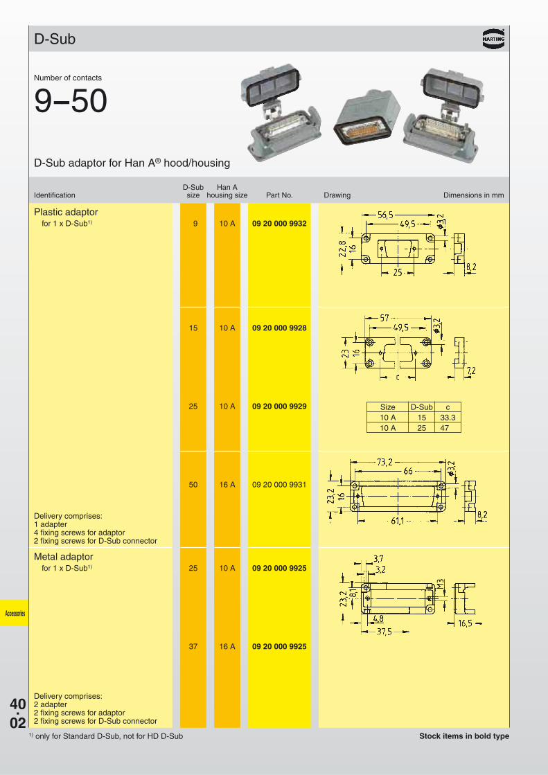
D-Sub adaptor for Han A® hood/housing
D-Sub
Plastic adaptorfor 1 x D-Sub1) 9 10 A 09 20 000 9932
15 10 A 09 20 000 9928
25 10 A 09 20 000 9929
50 16 A 09 20 000 9931
Metal adaptorfor 1 x D-Sub1) 25 10 A 09 20 000 9925
37 16 A 09 20 000 9925
Number of contacts
9--50
Size D-Sub c10 A 15 33.310 A 25 47.0
Delivery comprises:1 adapter4 fixing screws for adaptor2 fixing screws for D-Sub connector
Delivery comprises:2 adapter2 fixing screws for adaptor2 fixing screws for D-Sub connector
Stock items in bold type1) only for Standard D-Sub, not for HD D-Sub
40.03
Mounting in hoodCharacter “T” visible
Accessories
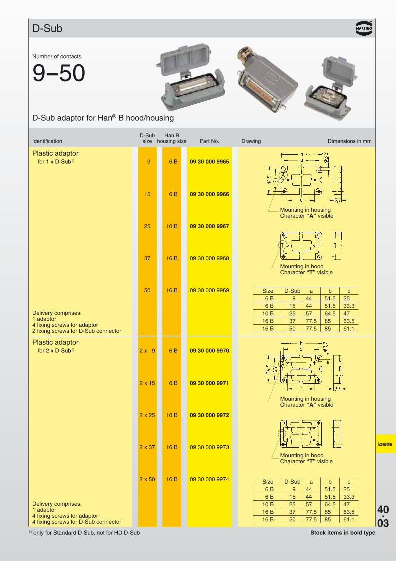
Number of contacts
9--50
D-Sub Han BIdentification size housing size Part No. Drawing Dimensions in mm
D-Sub adaptor for Han® B hood/housing
D-Sub
Plastic adaptorfor 1 x D-Sub1) 9 6 B 09 30 000 9965
15 6 B 09 30 000 9966
25 10 B 09 30 000 9967
37 16 B 09 30 000 9968
50 16 B 09 30 000 9969
Plastic adaptorfor 2 x D-Sub1) 2 x 9 6 B 09 30 000 9970
2 x 15 6 B 09 30 000 9971
2 x 25 10 B 09 30 000 9972
2 x 37 16 B 09 30 000 9973
2 x 50 16 B 09 30 000 9974
Size D-Sub a b c6 B 9 44.0 51.5 25.06 B 15 44.0 51.5 33.3
10 B 25 57.0 64.5 47.016 B 37 77.5 85.0 63.516 B 50 77.5 85.0 61.1
Size D-Sub a b c6 B 9 44.0 51.5 25.06 B 15 44.0 51.5 33.3
10 B 25 57.0 64.5 47.016 B 37 77.5 85.0 63.516 B 50 77.5 85.0 61.1
Mounting in housingCharacter “A” visible
Mounting in housingCharacter “A” visible
Mounting in hoodCharacter “T” visible
Delivery comprises:1 adaptor4 fixing screws for adaptor2 fixing screws for D-Sub connector
Delivery comprises:1 adaptor4 fixing screws for adaptor4 fixing screws for D-Sub connector
Stock items in bold type1) only for Standard D-Sub, not for HD D-Sub
40.04
Accessories
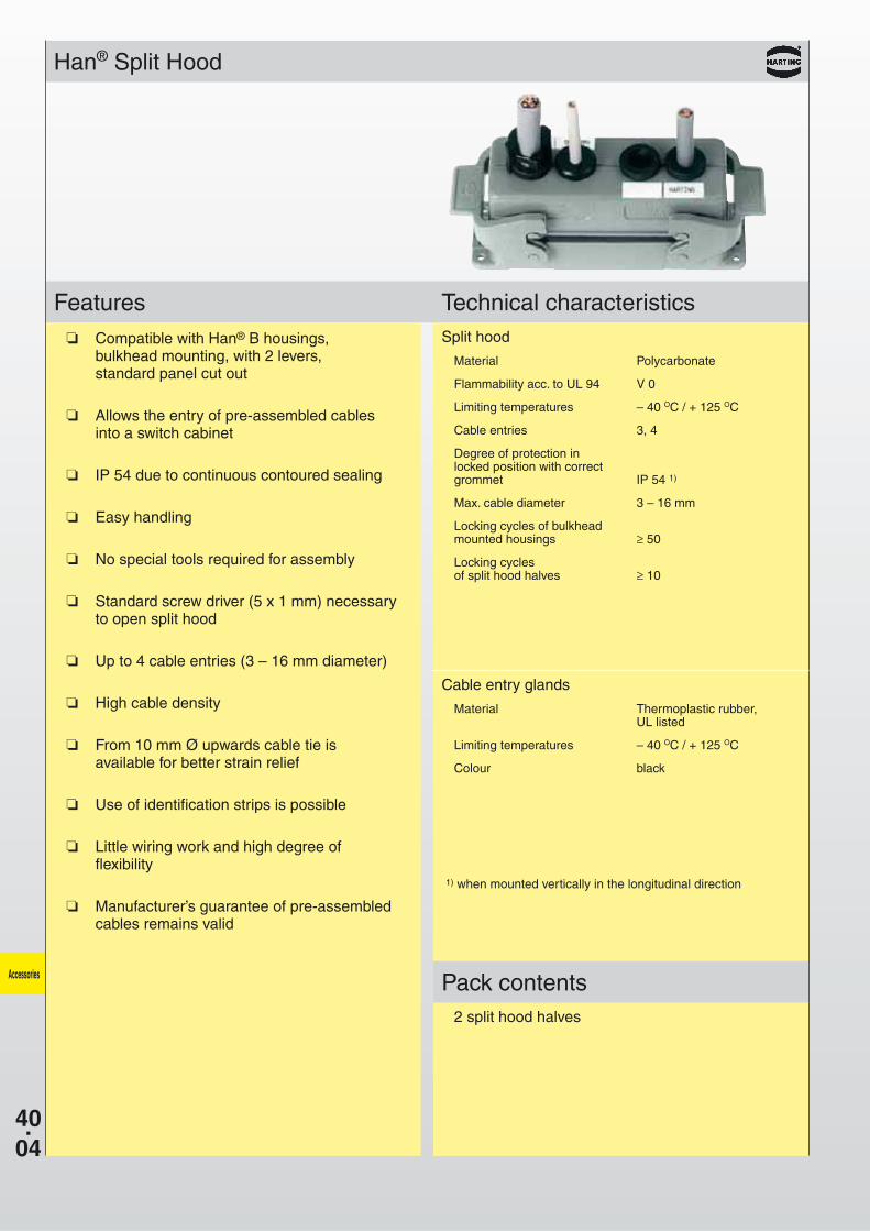
Han® Split Hood
Features Technical characteristics
Pack contents
Compatible with Han® B housings, bulkhead mounting, with 2 levers, standard panel cut out
Allows the entry of pre-assembled cablesinto a switch cabinet
IP 54 due to continuous contoured sealing
Easy handling
No special tools required for assembly
Standard screw driver (5 x 1 mm) necessaryto open split hood
Up to 4 cable entries (3 – 16 mm diameter)
High cable density
From 10 mm Ø upwards cable tie isavailable for better strain relief
Use of identification strips is possible
Little wiring work and high degree offlexibility
Manufacturer’s guarantee of pre-assembledcables remains valid
Split hood
Material Polycarbonate
Flammability acc. to UL 94 V 0
Limiting temperatures – 40 OC / + 125 OC
Cable entries 3, 4
Degree of protection inlocked position with correctgrommet IP 54 1)
Max. cable diameter 3 – 16 mm
Locking cycles of bulkheadmounted housings ≥ 50
Locking cyclesof split hood halves ≥ 10
Cable entry glands
Material Thermoplastic rubber,UL listed
Limiting temperatures – 40 OC / + 125 OC
Colour black
1) when mounted vertically in the longitudinal direction
2 split hood halves
40.05
Accessories
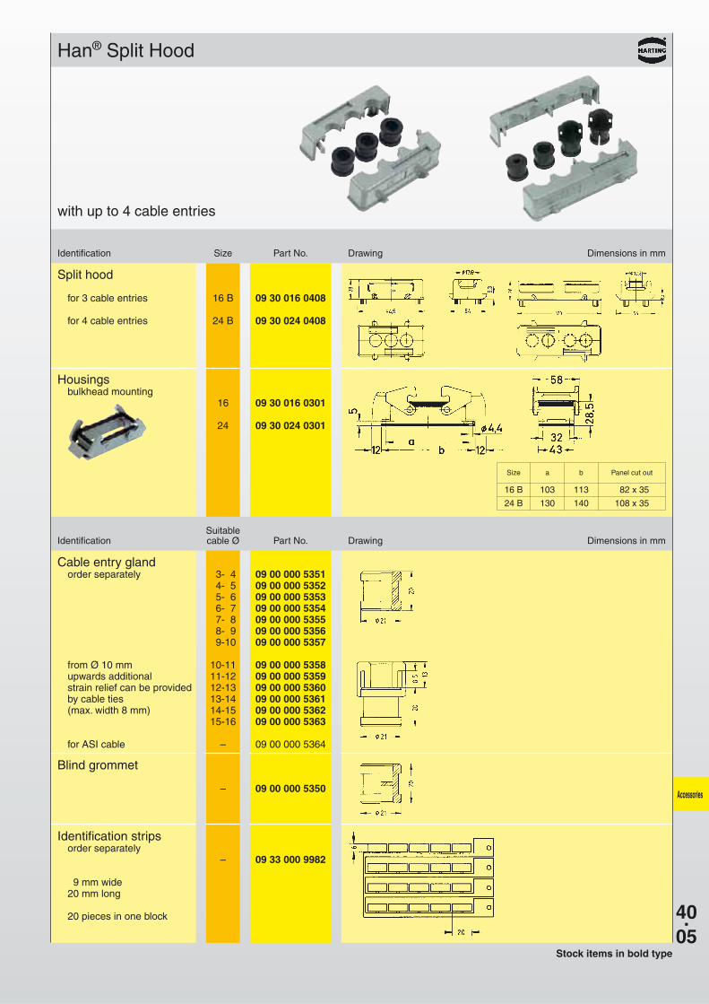
Han® Split Hood
Identification Size Part No. Drawing Dimensions in mm
SuitableIdentification cable Ø Part No. Drawing Dimensions in mm
with up to 4 cable entries
Cable entry glandorder separately 3- 4 09 00 000 5351
4- 5 09 00 000 53525- 6 09 00 000 53536- 7 09 00 000 53547- 8 09 00 000 53558- 9 09 00 000 53569-10 09 00 000 5357
from Ø 10 mm 10-11 09 00 000 5358upwards additional 11-12 09 00 000 5359strain relief can be provided 12-13 09 00 000 5360by cable ties 13-14 09 00 000 5361(max. width 8 mm) 14-15 09 00 000 5362
15-16 09 00 000 5363
for ASI cable – 09 00 000 5364
Blind grommet
– 09 00 000 5350
Identification stripsorder separately
– 09 33 000 9982
9 mm wide20 mm long
20 pieces in one block
Stock items in bold type
Size a b Panel cut out
16 B 103 113 82 x 35
24 B 130 140 108 x 35
Split hood
for 3 cable entries 16 B 09 30 016 0408
for 4 cable entries 24 B 09 30 024 0408
Housingsbulkhead mounting
16 09 30 016 0301
24 09 30 024 0301
40.06
Accessories
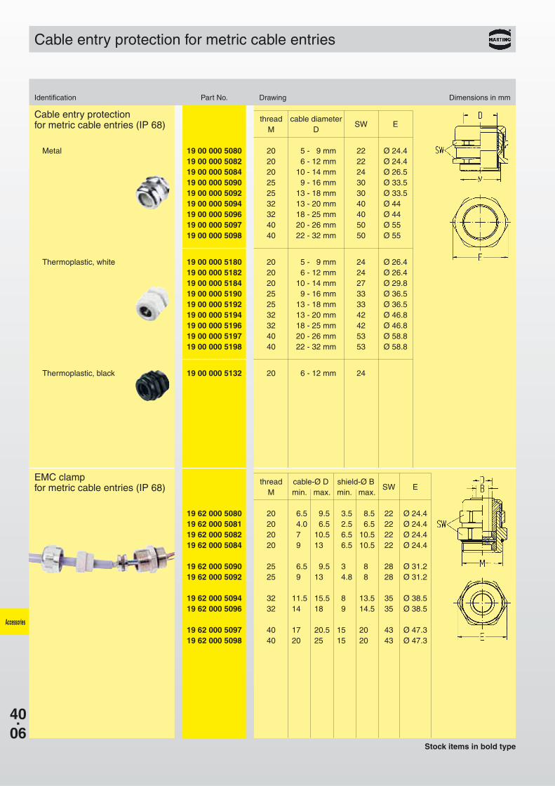
Cable entry protection for metric cable entries
Stock items in bold type
19 00 000 5180 20 5 - 9 mm 24 Ø 26.419 00 000 5182 20 6 - 12 mm 24 Ø 26.419 00 000 5184 20 10 - 14 mm 27 Ø 29.819 00 000 5190 25 9 - 16 mm 33 Ø 36.519 00 000 5192 25 13 - 18 mm 33 Ø 36.519 00 000 5194 32 13 - 20 mm 42 Ø 46.819 00 000 5196 32 18 - 25 mm 42 Ø 46.819 00 000 5197 40 20 - 26 mm 53 Ø 58.819 00 000 5198 40 22 - 32 mm 53 Ø 58.8
19 00 000 5080 20 5 - 9 mm 22 Ø 24.419 00 000 5082 20 6 - 12 mm 22 Ø 24.419 00 000 5084 20 10 - 14 mm 24 Ø 26.519 00 000 5090 25 9 - 16 mm 30 Ø 33.519 00 000 5092 25 13 - 18 mm 30 Ø 33.519 00 000 5094 32 13 - 20 mm 40 Ø 44.019 00 000 5096 32 18 - 25 mm 40 Ø 44.019 00 000 5097 40 20 - 26 mm 50 Ø 55.019 00 000 5098 40 22 - 32 mm 50 Ø 55.0
Thermoplastic, white
19 00 000 5132 20 6 - 12 mm 24Thermoplastic, black
Metal
Cable entry protectionfor metric cable entries (IP 68)
EMC clampfor metric cable entries (IP 68)
thread cable-Ø D shield-Ø BSW E
M min. max. min. max.
19 62 000 5080 20 6.5 9.5 3.5 8.5 22 Ø 24.419 62 000 5081 20 4.0 6.5 2.5 6.5 22 Ø 24.419 62 000 5082 20 7.0 10.5 6.5 10.5 22 Ø 24.419 62 000 5084 20 9.0 13.0 6.5 10.5 22 Ø 24.4
19 62 000 5090 25 6.5 9.5 3.0 8.0 28 Ø 31.219 62 000 5092 25 9.0 13.0 4.8 8.0 28 Ø 31.2
19 62 000 5094 32 11.5 15.5 8.0 13.5 35 Ø 38.519 62 000 5096 32 14.0 18.0 9.0 14.5 35 Ø 38.5
19 62 000 5097 40 17.0 20.5 15.0 20.0 43 Ø 47.319 62 000 5098 40 20.0 25.0 15.0 20.0 43 Ø 47.3
Identification Part No. Drawing Dimensions in mm
thread cable diameterSW E
M D
40.07
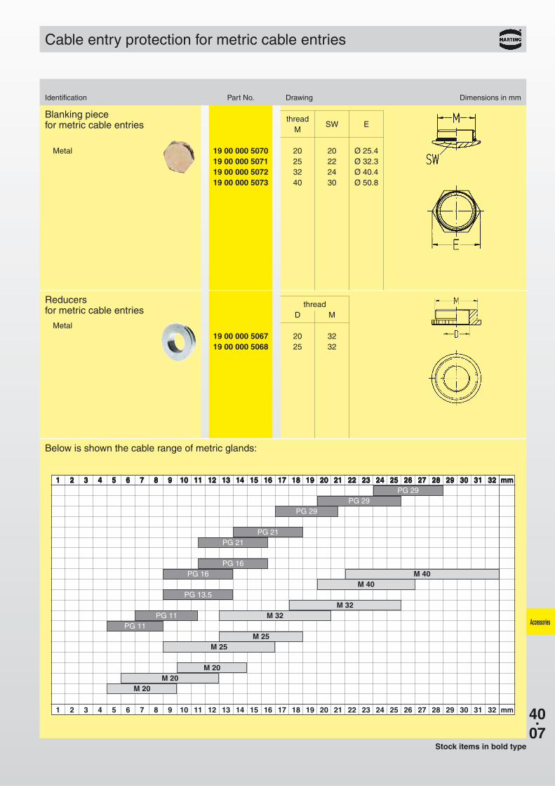
1 2 3 4 5 6 7 8 9 10 11 12 13 14 15 16 17 18 19 20 21 22 23 24 25 26 27 28 29 30 31 32 mm
1 2 3 4 5 6 7 8 9 10 11 12 13 14 15 16 17 18 19 20 21 22 23 24 25 26 27 28 29 30 31 32 mm
M 40M 40
M 32M 32
M 25M 25
M 20M 20
M 20
1 2 3 4 5 6 7 8 9 10 11 12 13 14 15 16 17 18 19 20 21 22 23 24 25 26 27 28 29 30 31 32 mm1 2 3 4 5 6 7 8 9 10 11 12 13 14 15 16 17 18 19 20 21 22 23 24 25 26 27 28 29 30 31 32 mmPG 29
PG 29PG 29
PG 21PG 21
PG 16PG 16
PG 13.5
PG 11PG 11
19 00 000 5067 20 3219 00 000 5068 25 32
Accessories
Cable entry protection for metric cable entries
Identification Part No. Drawing Dimensions in mm
Stock items in bold type
Metal
Blanking piecefor metric cable entries
Metal
Reducersfor metric cable entries
Below is shown the cable range of metric glands:
threadSW E
M
threadD M
19 00 000 5070 20 20 Ø 25.419 00 000 5071 25 22 Ø 32.319 00 000 5072 32 24 Ø 40.419 00 000 5073 40 30 Ø 50.8
40.08
A
C
D
B
A B
C D
Accessories
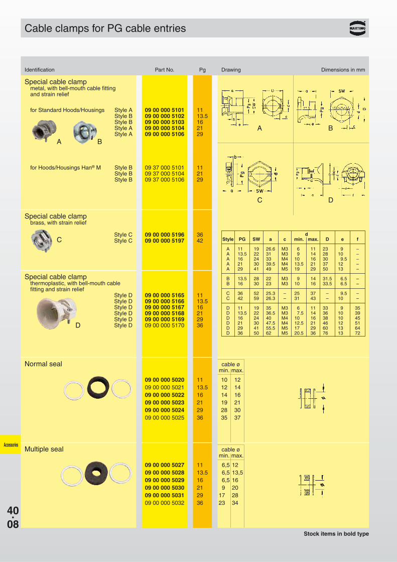
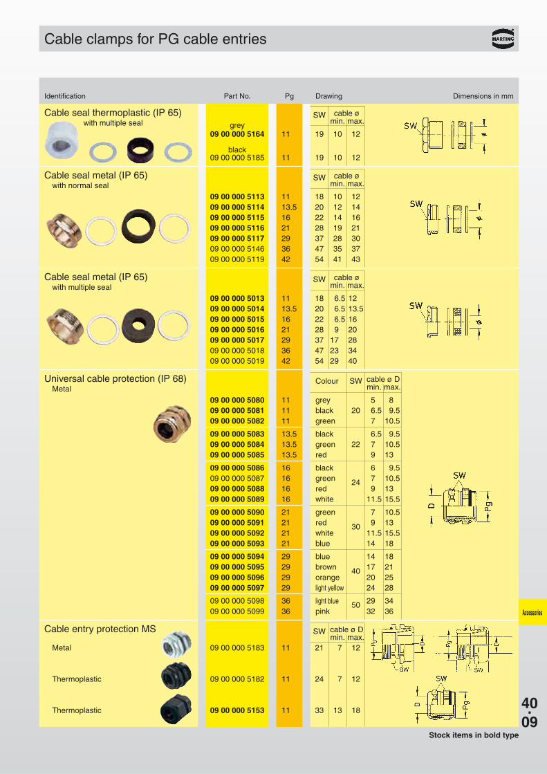
Cable clamps for PG cable entries
Identification Part No. Pg Drawing Dimensions in mm
Special cable clampthermoplastic, with bell-mouth cablefitting and strain relief
Style D 09 00 000 5165 11Style D 09 00 000 5166 13.5Style D 09 00 000 5167 16Style D 09 00 000 5168 21Style D 09 00 000 5169 29Style D 09 00 000 5170 36
Special cable clampmetal, with bell-mouth cable fittingand strain relief
for Standard Hoods/Housings Style A 09 00 000 5101 11Style B 09 00 000 5102 13.5Style B 09 00 000 5103 16Style A 09 00 000 5104 21Style A 09 00 000 5106 29
for Hoods/Housings Han® M Style B 09 37 000 5101 11Style B 09 37 000 5104 21Style B 09 37 000 5106 29
Normal seal cable ømin. max.
09 00 000 5020 11 10 1209 00 000 5021 13.5 12 1409 00 000 5022 16 14 1609 00 000 5023 21 19 2109 00 000 5024 29 28 3009 00 000 5025 36 35 37
Multiple seal cable ømin. max.
09 00 000 5027 11 6,5 12,509 00 000 5028 13.5 6,5 13,509 00 000 5029 16 6,5 16,509 00 000 5030 21 9,5 20,509 00 000 5031 29 17,5 28,509 00 000 5032 36 23,5 34,5
Special cable clampbrass, with strain relief
Style C 09 00 000 5196 36Style C 09 00 000 5197 42
dStyle PG SW a c min. max. D e f
A 11.5 19 26.6 M3 6.5 11 23.5 9.5 –A 13.5 22 31.5 M3 9.5 14 28.5 10.5 –A 16.5 24 33.5 M4 10.5 16 30.5 9.5 –A 21.5 30 39.5 M4 13.5 21 37.5 12.5 –A 29.5 41 49.5 M5 19.5 29 50.5 13.5 –
B 13.5 28 22.5 M3 9.5 14 31.5 6.5 –B 16.5 30 23.5 M3 10.5 16 33.5 6.5 –
C 36.5 52 25.3 – 25.5 37 – 9.5 –C 42.5 59 26.3 – 31.5 43 – 10.5 –
D 11.5 19 35.5 M3 6.5 11 33.5 9.5 35D 13.5 22 36.5 M3 7.5 14 36.5 10.5 39D 16.5 24 40.5 M4 10.5 16 38.5 10.5 45D 21.5 30 47.5 M4 12.5 21 46.5 12.5 51D 29.5 41 55.5 M5 17.5 29 60.5 13.5 64D 36.5 50 62.5 M5 20.5 36 76.5 13.5 72
Stock items in bold type
40.09
Universal cable protection (IP 68) Colour SW cable ø DMetal min. max.
09 00 000 5080 11 grey 5.5 8.509 00 000 5081 11 black 20 6.5 9.509 00 000 5082 11 green 7.5 10.5
09 00 000 5083 13.5 black 6.5 9.509 00 000 5084 13.5 green 22 7.5 10.509 00 000 5085 13.5 red 9.5 13.5
09 00 000 5086 16 black 6.5 9.509 00 000 5087 16 green 24 7.5 10.509 00 000 5088 16 red 9.5 13.509 00 000 5089 16 white 11.5 15.5
09 00 000 5090 21 green 7.5 10.509 00 000 5091 21 red 30 9.5 13.509 00 000 5092 21 white 11.5 15.509 00 000 5093 21 blue 14.5 18.5
09 00 000 5094 29 blue 14.5 18.509 00 000 5095 29 brown 40 17.5 21.509 00 000 5096 29 orange 20.5 25.509 00 000 5097 29 light yellow 24.5 28.5
09 00 000 5098 36 light blue 50 29.5 34.509 00 000 5099 36 pink 32.5 36.5 Accessories
Cable clamps for PG cable entries
Identification Part No. Pg Drawing Dimensions in mm
Cable seal metal (IP 65) SW cable øwith normal seal min. max.
09 00 000 5113 11 18 10 1209 00 000 5114 13.5 20 12 1409 00 000 5115 16 22 14 1609 00 000 5116 21 28 19 2109 00 000 5117 29 37 28 3009 00 000 5146 36 47 35 3709 00 000 5119 42 54 41 43
Cable seal thermoplastic (IP 65) SW cable øwith multiple seal grey min. max.
09 00 000 5164 11 19 10 12
black09 00 000 5185 11 19 10 12
Cable seal metal (IP 65) SW cable øwith multiple seal min. max.
09 00 000 5013 11 18 6.5 12,509 00 000 5014 13.5 20 6.5 13.509 00 000 5015 16 22 6.5 16,009 00 000 5016 21 28 9,0 20,009 00 000 5017 29 37 17,0 28,009 00 000 5018 36 47 23,0 34,009 00 000 5019 42 54 29,0 40,0
Cable entry protection MS SW cable ø Dmin. max.
Metal 09 00 000 5183 11 21 7 12
Thermoplastic 09 00 000 5182 11 24 7 12
Thermoplastic 09 00 000 5153 11 33 13 18
Stock items in bold type
40.10
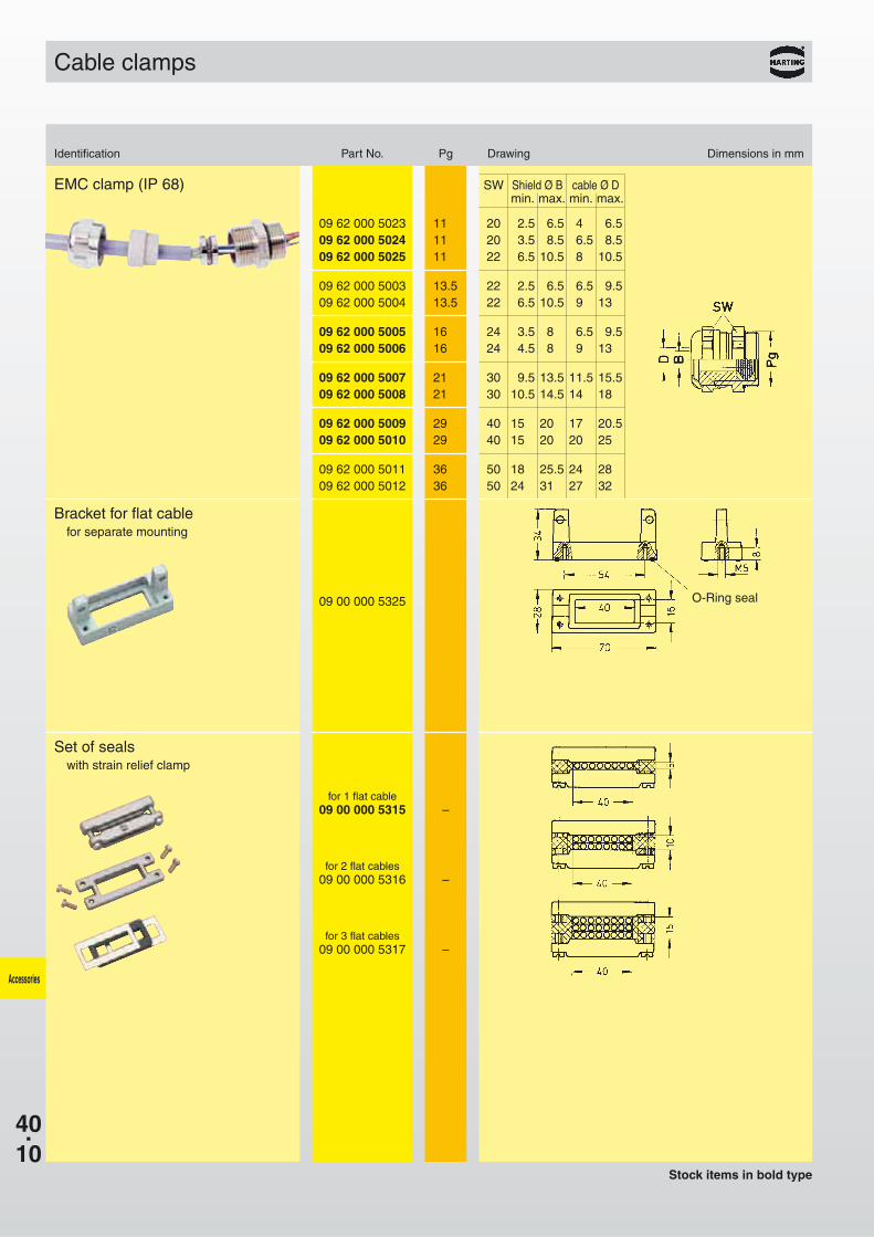
EMC clamp (IP 68) SW Shield Ø B cable Ø Dmin. max. min. max.
09 62 000 5023 11 20 2.5 6.5 4.5 6.509 62 000 5024 11 20 3.5 8.5 6.5 8.509 62 000 5025 11 22 6.5 10.5 8.5 10.5
09 62 000 5003 13.5 22 2.5 6.5 6.5 9.509 62 000 5004 13.5 22 6.5 10.5 9.5 13.5
09 62 000 5005 16 24 3.5 8.5 6.5 9.509 62 000 5006 16 24 4.5 8.5 9.5 13.5
09 62 000 5007 21 30 9.5 13.5 11.5 15.509 62 000 5008 21 30 10.5 14.5 14.5 18.5
09 62 000 5009 29 40 15.5 20.5 17.5 20.509 62 000 5010 29 40 15.5 20.5 20.5 25.5
09 62 000 5011 36 50 18.5 25.5 24.5 28.509 62 000 5012 36 50 24.5 31.5 27.5 32.5
Accessories
Cable clamps
Identification Part No. Pg Drawing Dimensions in mm
Stock items in bold type
Set of sealswith strain relief clamp
for 1 flat cable09 00 000 5315 –
for 2 flat cables09 00 000 5316 –
for 3 flat cables09 00 000 5317 –
Bracket for flat cablefor separate mounting
09 00 000 5325 O-Ring seal
40.11
Do not operate under load
Ne pas actionner sous charge
G + L
09 30 000 9958
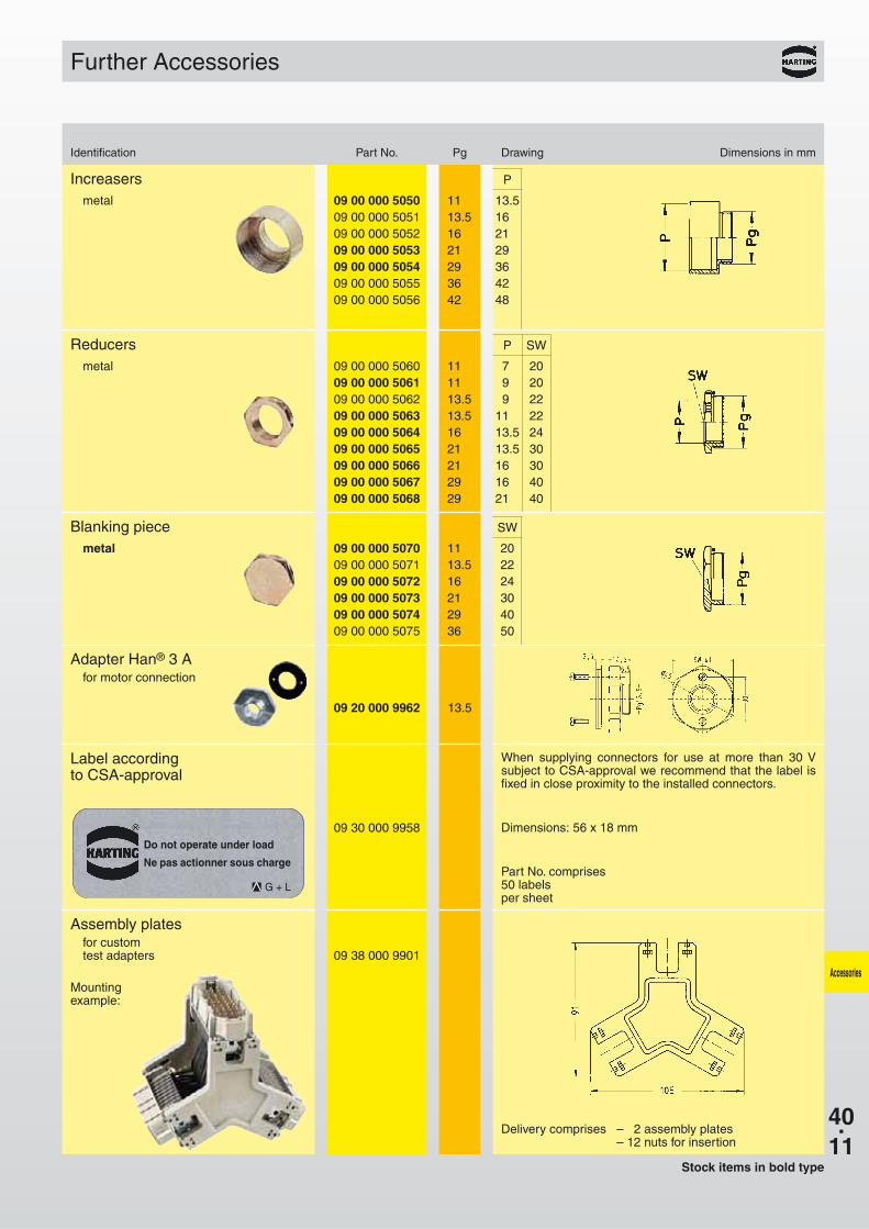
Further Accessories
Identification Part No. Pg Drawing Dimensions in mm
Stock items in bold type
Delivery comprises – 2 assembly plates– 12 nuts for insertion
Accessories
Increasers P
metal 09 00 000 5050 11 13.509 00 000 5051 13.5 16.009 00 000 5052 16 21.009 00 000 5053 21 29.009 00 000 5054 29 36.009 00 000 5055 36 42.009 00 000 5056 42 48.0
Reducers P SW
metal 09 00 000 5060 11 7.0 2009 00 000 5061 11 9.0 2009 00 000 5062 13.5 9.0 2209 00 000 5063 13.5 11.0 2209 00 000 5064 16 13.5 2409 00 000 5065 21 13.5 3009 00 000 5066 21 16.0 3009 00 000 5067 29 16.0 4009 00 000 5068 29 21.0 40
Blanking piece SW
metal 09 00 000 5070 11 2009 00 000 5071 13.5 2209 00 000 5072 16 2409 00 000 5073 21 3009 00 000 5074 29 4009 00 000 5075 36 50
Adapter Han® 3 Afor motor connection
09 20 000 9962 13.5
Label accordingto CSA-approval
When supplying connectors for use at more than 30 Vsubject to CSA-approval we recommend that the label isfixed in close proximity to the installed connectors.
Dimensions: 56 x 18 mm
Part No. comprises50 labelsper sheet
Assembly platesfor customtest adapters 09 38 000 9901
Mountingexample:
40.12
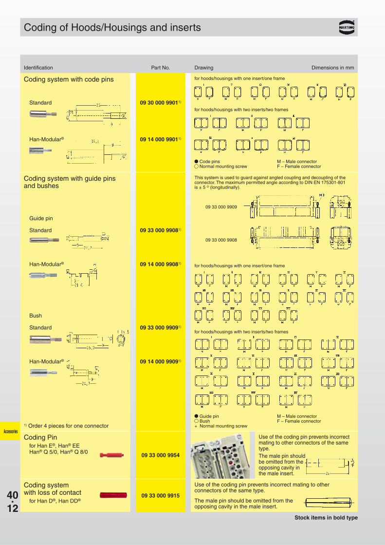
09 33 000 9909
09 33 000 9908
Standard 09 30 000 99011)
Standard 09 33 000 99081)
Standard 09 33 000 99091)
Han-Modular® 09 14 000 99011)
Han-Modular® 09 14 000 99081)
Han-Modular® 09 14 000 99091)
09 33 000 9954
09 33 000 9915
Accessories
Coding system with code pins
Coding system with guide pinsand bushes
Guide pin
1) Order 4 pieces for one connector
Bush
Coding of Hoods/Housings and inserts
for hoods/housings with one insert/one frame
for hoods/housings with one insert/one frame
for hoods/housings with two inserts/two frames
for hoods/housings with two inserts/two frames
Code pins M – Male connectorNormal mounting screw F – Female connector
This system is used to guard against angled coupling and decoupling of theconnector. The maximum permitted angle according to DIN EN 175301-801 is ± 5 O (longitudinally).
Guide pin M – Male connectorBush F – Female connector
+ Normal mounting screw
Identification Part No. Drawing Dimensions in mm
Stock items in bold type
Coding Pinfor Han E®, Han® EEHan® Q 5/0, Han® Q 8/0
Coding systemwith loss of contact
for Han D®, Han DD®
Use of the coding pin prevents incorrectmating to other connectors of the sametype.The male pin should be omitted from the opposing cavity in the male insert.
Use of the coding pin prevents incorrect mating to other connectors of the same type.
The male pin should be omitted from theopposing cavity in the male insert.
40.13
Features Technical characteristics
Pack contents
3 PE-terminations
Screws with ± head
Self lifting washer
Suitable for use with all inserts of the Han® 6 B to 24 B size(except Han® ESS-inserts)
Suitable in hood high construction
Termination points 3
Termination wire gauge 0.5–2.5 mm²AWG 20-14
Material copper alloy
Surface Ni
Contact resistance ≤ 3 m Ω
Delivery comprises
- Multiple ground connection
- Fixing screw M4 with washer
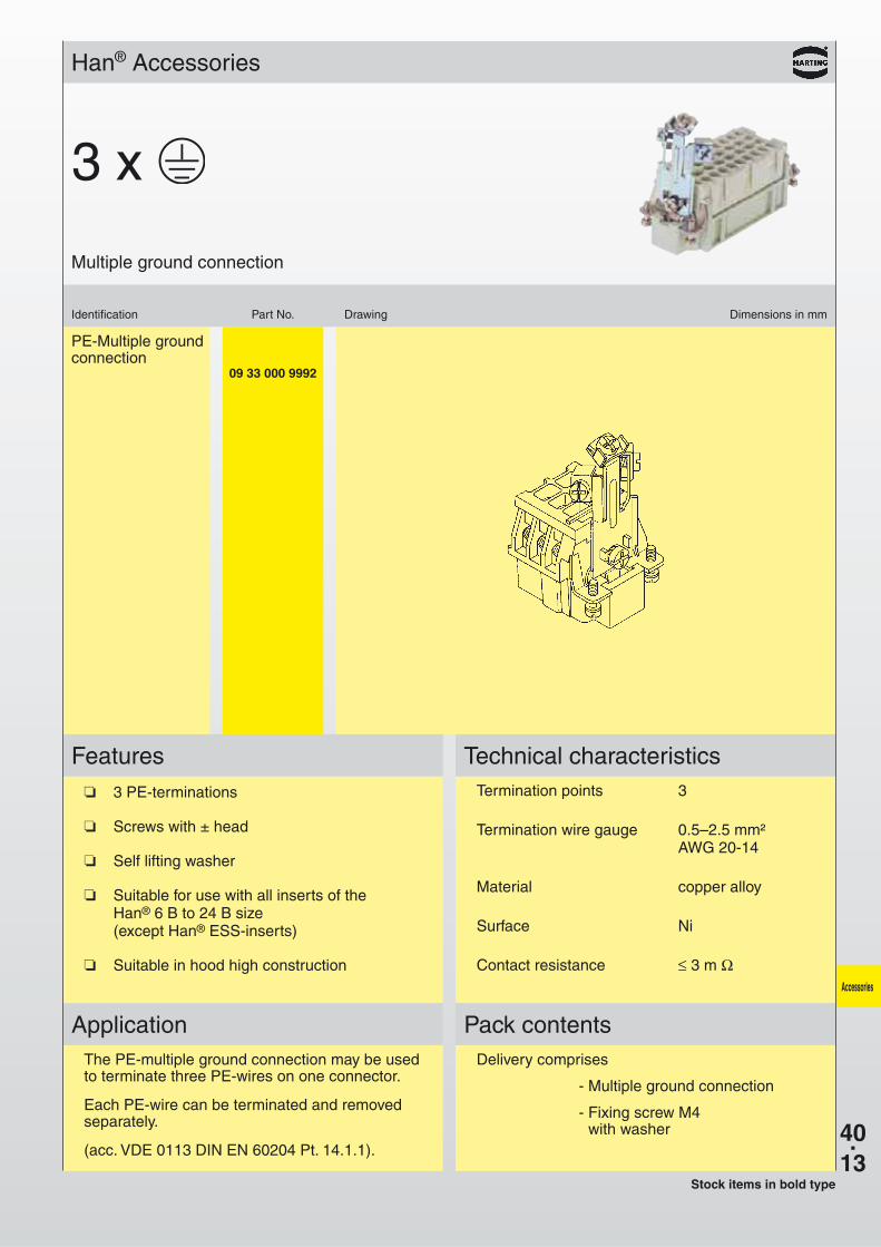
ApplicationThe PE-multiple ground connection may be usedto terminate three PE-wires on one connector.
Each PE-wire can be terminated and removedseparately.
(acc. VDE 0113 DIN EN 60204 Pt. 14.1.1).
PE-Multiple groundconnection
09 33 000 9992
Han® Accessories
Identification Part No. Drawing Dimensions in mm
Multiple ground connection
Stock items in bold type
3 x
Accessories
40.14
AccessoriesFeatures Pack contents
When using inserts without hoods or housingsand requiring a strain relief this system is suitablefor all rectangular connectors of series Han DD®,Han® 40-64 D, Han E® / Han® ES, Han® HsB, HanHv E® / Han® Hv ES, Han® EE, Han® K 8/24.Fitted at the opposite end to the PE-termination.
Delivery comprises
- Cable clamp fittingwith 2 screws M3
- Fixing screw M4with washer
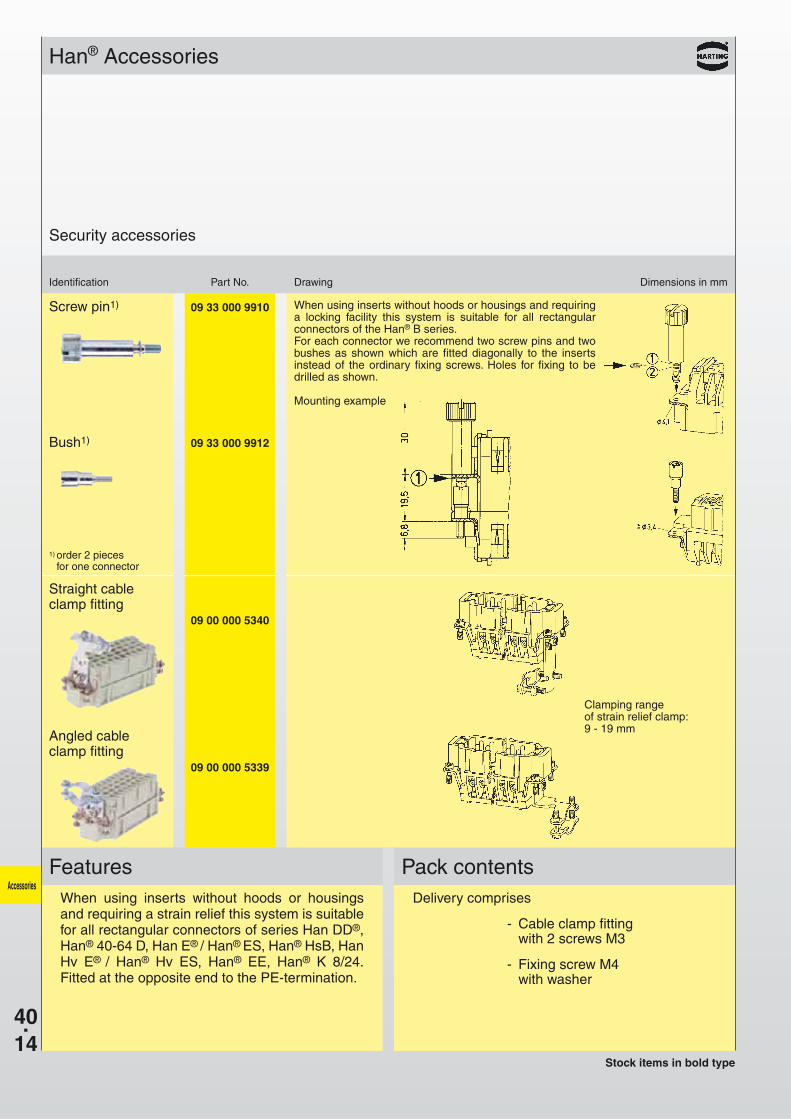
Screw pin1) 09 33 000 9910
Bush1) 09 33 000 9912
1) order 2 pieces for one connector
Straight cableclamp fitting
09 00 000 5340
Angled cableclamp fitting
09 00 000 5339
Han® Accessories
Identification Part No. Drawing Dimensions in mm
Security accessories
When using inserts without hoods or housings and requiringa locking facility this system is suitable for all rectangularconnectors of the Han® B series.For each connector we recommend two screw pins and twobushes as shown which are fitted diagonally to the insertsinstead of the ordinary fixing screws. Holes for fixing to bedrilled as shown.
Mounting example
Stock items in bold type
Clamping range of strain relief clamp:9 - 19 mm
40.15
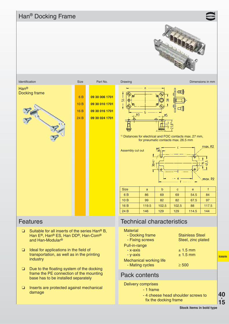
Han®
Docking frame6 B 09 30 006 1701
10 B 09 30 010 1701
16 B 09 30 016 1701
24 B 09 30 024 1701
Han® Docking Frame
Identification Size Part No. Drawing Dimensions in mm
Accessories
Features Technical characteristics
Pack contents
Suitable for all inserts of the series Han® B,Han E®, Han® ES, Han DD®, Han-Com®
and Han-Modular®
Ideal for applications in the field oftransportation, as well as in the printingindustry
Due to the floating system of the dockingframe the PE connection of the mountingbase has to be installed separately
Inserts are protected against mechanicaldamage
Material- Docking frame Stainless Steel- Fixing screws Steel, zinc plated
Pull-in-range- x-axis ± 1.5 mm- y-axis ± 1.5 mm
Mechanical working life- Mating cycles ≥ 500
Delivery comprises- 1 frame- 4 cheese head shoulder screws to
fix the docking frame
Assembly cut out
1) Distances for electrical and FOC contacts max. 27 mm, for pneumatic contacts max. 26.5 mm
Stock items in bold type
Size a b c e f
6 B 86,5 69,5 69,5 54.5 84,5
10 B 99,5 82,5 82,5 67.5 97,5
16 B 119.5 102.5 102.5 88.5 117.5
24 B 146.5 129.5 129.5 114.5 144.5
40.16
Accessories
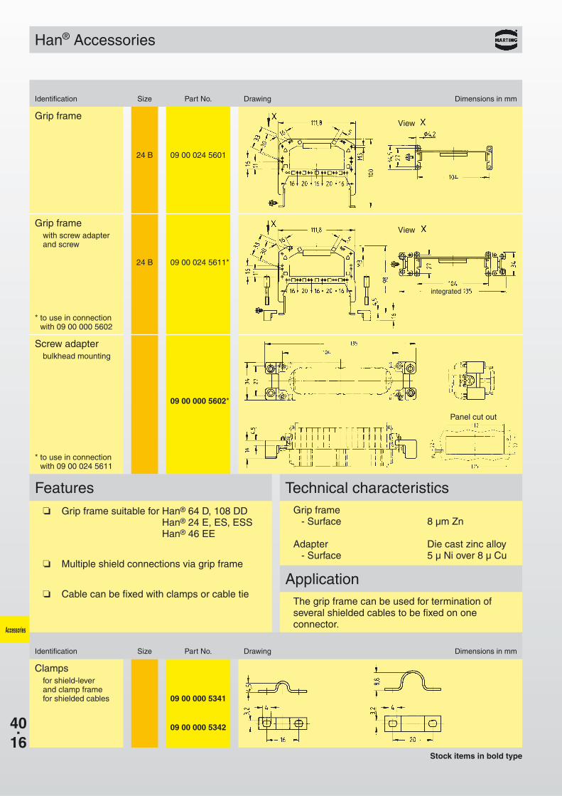
Grip frame
24 B 09 00 024 5601
Grip framewith screw adapterand screw
24 B *09 00 024 5611*
Screw adapterbulkhead mounting
*09 00 000 5602*
Clampsfor shield-leverand clamp framefor shielded cables 09 00 000 5341
09 00 000 5342
Stock items in bold type
Application
Grip frame suitable for Han® 64 D, 108 DDHan® 24 E, ES, ESSHan® 46 EE
Multiple shield connections via grip frame
Cable can be fixed with clamps or cable tie
Grip frame- Surface 8 µm Zn
Adapter Die cast zinc alloy- Surface 5 µ Ni over 8 µ Cu
The grip frame can be used for termination ofseveral shielded cables to be fixed on oneconnector.
Han® Accessories
Identification Size Part No. Drawing Dimensions in mm
Identification Size Part No. Drawing Dimensions in mm
Features Technical characteristics
View
View
integrated
* to use in connectionwith 09 00 000 5602
* to use in connectionwith 09 00 024 5611
Panel cut out
40.17
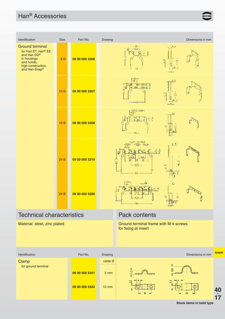
6 B 09 00 000 5206
10 B 09 00 000 5207
16 B 09 00 000 5208
24 B 09 00 000 5210
24 B 09 00 000 5280
09 00 000 5341 5 mm
09 00 000 5342 10 mm
Accessories
Stock items in bold type
Han® Accessories
Identification Size Part No. Drawing Dimensions in mm
Ground terminalfor Han E®, Han® EEand Han DD®
in housings and hoods, high construction, and Han-Snap®
cable ØClampfor ground terminal
Pack contentsMaterial: steel, zinc plated Ground terminal frame with M 4 screws
for fixing at insert
Identification Part No. Drawing Dimensions in mm
Technical characteristics
40.18
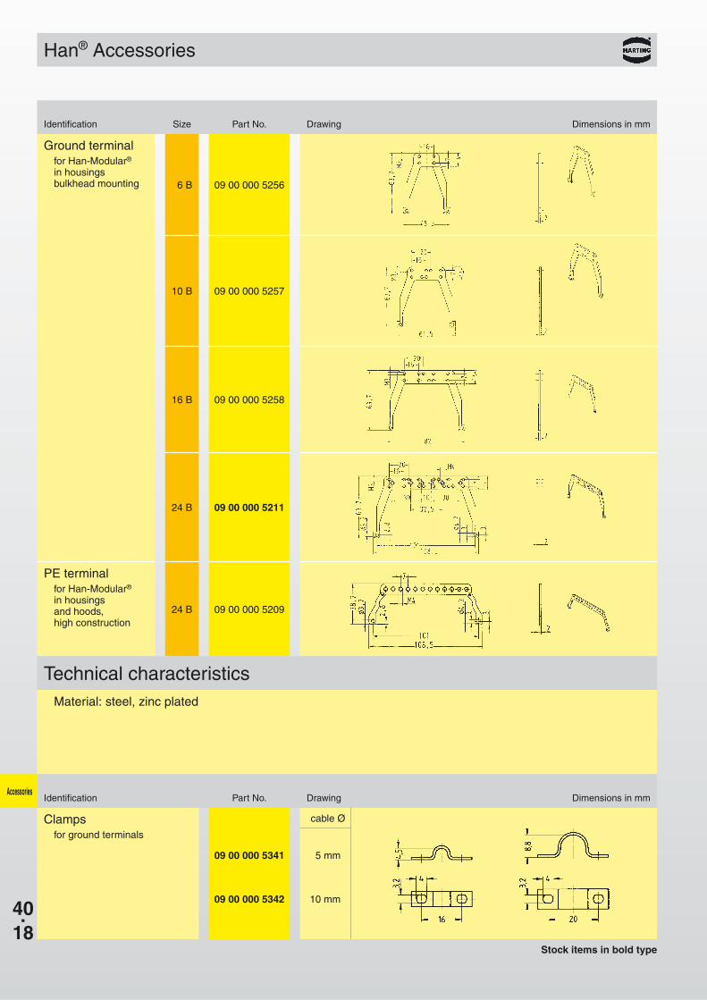
6 B 09 00 000 5256
10 B 09 00 000 5257
16 B 09 00 000 5258
24 B 09 00 000 5211
24 B 09 00 000 5209
09 00 000 5341 5 mm
09 00 000 5342 10 mm
Accessories
Stock items in bold type
Han® Accessories
Identification Size Part No. Drawing Dimensions in mm
Technical characteristics
cable ØClampsfor ground terminals
Identification Part No. Drawing Dimensions in mm
Ground terminalfor Han-Modular®
in housingsbulkhead mounting
PE terminalfor Han-Modular®
in housings and hoods, high construction
Material: steel, zinc plated
40.19
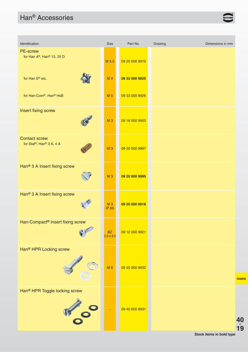
M 4 09 33 000 9925
M 5 09 33 000 9926
M 3 09 16 000 9903
M 3 09 30 000 9997
M 3 09 20 000 9995
M 3 09 20 000 9918IP 65
M 6 09 40 000 9932
– 09 40 000 9931
Accessories
Stock items in bold type
Han® Accessories
Identification Size Part No. Drawing Dimensions in mm
PE-screwfor Han A®, Han® 15, 25 D
for Han E® etc.
for Han-Com®, Han® HsB
Insert fixing screw
Contact screwfor Staf®, Han® 3 A, 4 A
Han® 3 A Insert fixing screw
Han® 3 A Insert fixing screw
BZ 09 12 000 99212.9 x 9.5
Han-Compact® Insert fixing screw
Han® HPR Locking screw
Han® HPR Toggle locking screw
M 3.5 09 20 000 9919
40.20
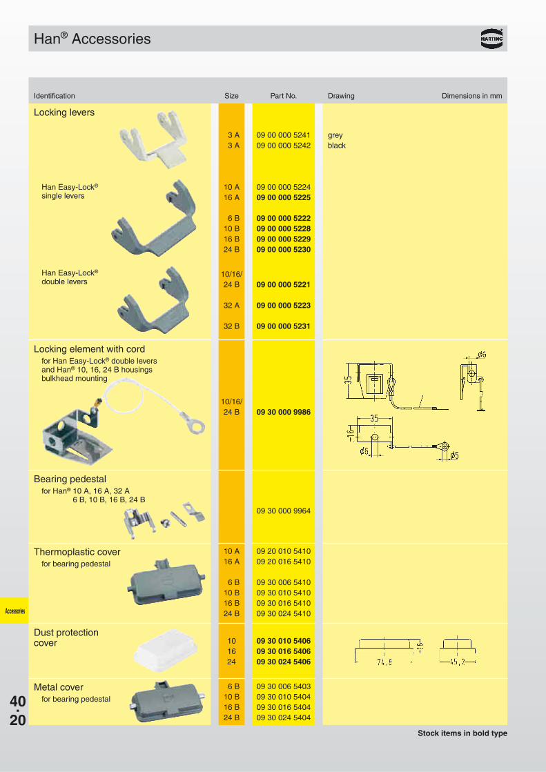
3 A 09 00 000 52413 A 09 00 000 5242
10 A 09 00 000 522416 A 09 00 000 5225
6 B 09 00 000 522210 B 09 00 000 522816 B 09 00 000 522924 B 09 00 000 5230
10/16/24 B 09 00 000 5221
32 A 09 00 000 5223
32 B 09 00 000 5231
09 30 000 9964
10 A 09 20 010 541016 A 09 20 016 5410
6 B 09 30 006 541010 B 09 30 010 541016 B 09 30 016 541024 B 09 30 024 5410
10/16/24 B 09 30 000 9986
6 B 09 30 006 540310 B 09 30 010 540416 B 09 30 016 540424 B 09 30 024 5404
10 09 30 010 540616 09 30 016 540624 09 30 024 5406
Accessories
greyblack
Locking levers
Stock items in bold type
Han® Accessories
Identification Size Part No. Drawing Dimensions in mm
Han Easy-Lock®
single levers
Han Easy-Lock®
double levers
Bearing pedestalfor Han® 10 A, 16 A, 32 A
6 B, 10 B, 16 B, 24 B
Locking element with cordfor Han Easy-Lock® double leversand Han® 10, 16, 24 B housingsbulkhead mounting
Thermoplastic coverfor bearing pedestal
Metal coverfor bearing pedestal
Dust protection cover
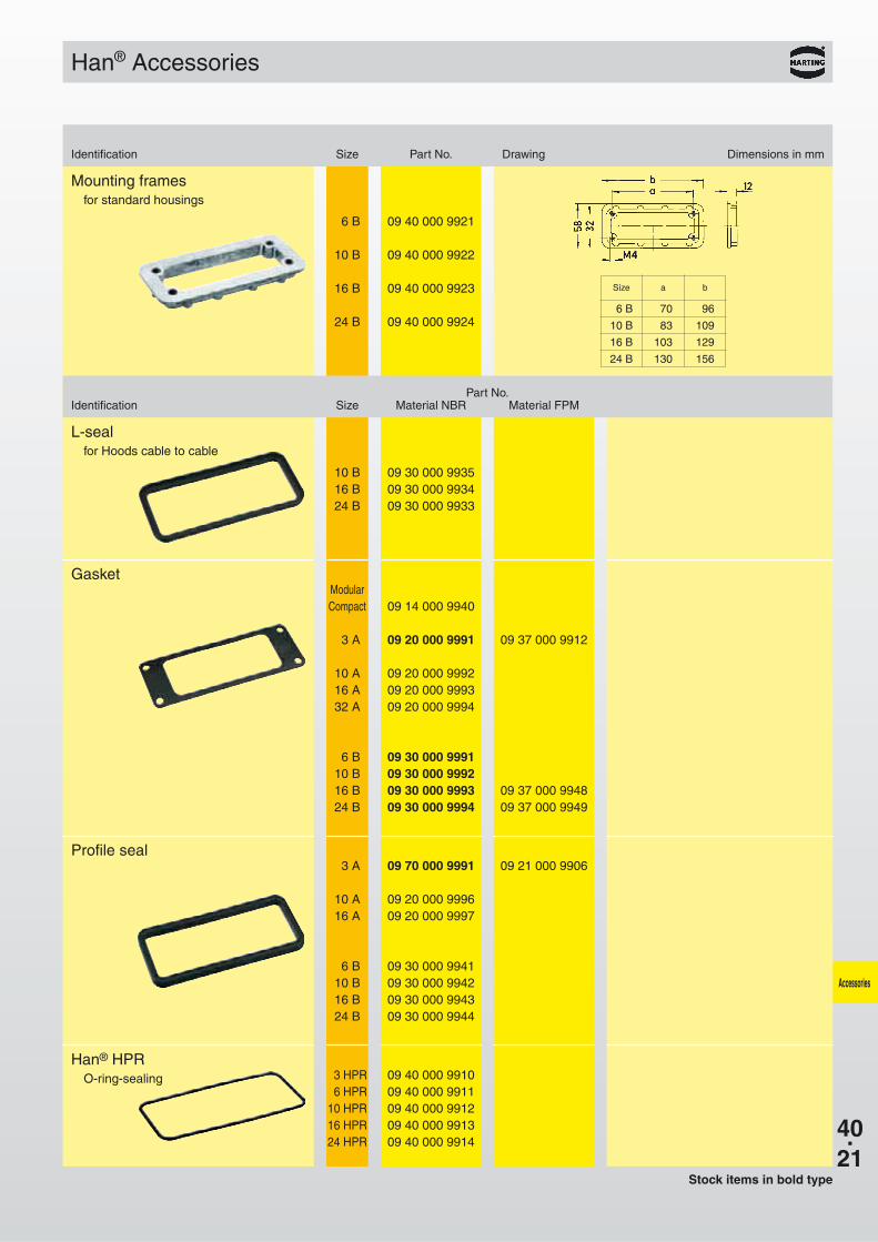
40.21
10 B 09 30 000 993516 B 09 30 000 993424 B 09 30 000 9933
6 B 09 40 000 9921
10 B 09 40 000 9922
16 B 09 40 000 9923
24 B 09 40 000 99246 B 70 96
10 B 83 109
16 B 103 129
24 B 130 156
3 HPR 09 40 000 99106 HPR 09 40 000 9911
10 HPR 09 40 000 991216 HPR 09 40 000 991324 HPR 09 40 000 9914
ModularCompact 09 14 000 9940
3 A 09 20 000 9991 09 37 000 9912
10 A 09 20 000 999216 A 09 20 000 999332 A 09 20 000 9994
6 B 09 30 000 999110 B 09 30 000 999216 B 09 30 000 9993 09 37 000 994824 B 09 30 000 9994 09 37 000 9949
3 A 09 70 000 9991 09 21 000 9906
10 A 09 20 000 999616 A 09 20 000 9997
6 B 09 30 000 994110 B 09 30 000 994216 B 09 30 000 994324 B 09 30 000 9944
Accessories
Gasket
Stock items in bold type
Han® Accessories
Identification Size Part No. Drawing Dimensions in mm
Part No.Identification Size Material NBR Material FPM
Profile seal
L-sealfor Hoods cable to cable
Han® HPRO-ring-sealing
Mounting framesfor standard housings
Size a b

40.22
Accessories
Notes