Embed Size (px)
Citation preview

Content 1. Experimental Setup .......................................................................................... 2
2. Theory............................................................................................................... 3
2.1. Reflection ...................................................................................................... 3
2.2. Snellius law ................................................................................................... 4
2.3. Parallel shift ................................................................................................... 5
2.4. Total internal reflection .................................................................................. 6
2.5. Beam propagation through prism .................................................................. 7
2.6. Prism dispersion ............................................................................................ 8
2.7. Grating dispersion ......................................................................................... 9
2.8. Birefringence and optical activity ................................................................. 13
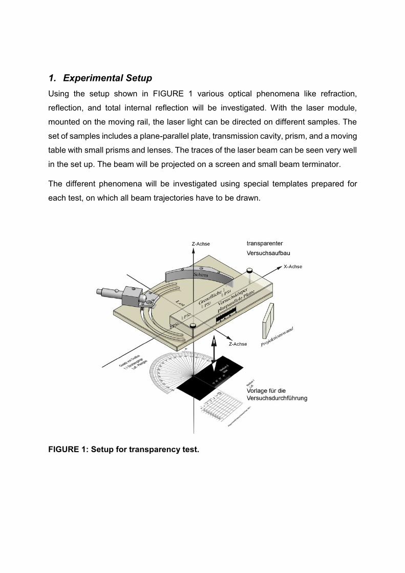
1. Experimental Setup
Using the setup shown in FIGURE 1 various optical phenomena like refraction,
reflection, and total internal reflection will be investigated. With the laser module,
mounted on the moving rail, the laser light can be directed on different samples. The
set of samples includes a plane-parallel plate, transmission cavity, prism, and a moving
table with small prisms and lenses. The traces of the laser beam can be seen very well
in the set up. The beam will be projected on a screen and small beam terminator.
The different phenomena will be investigated using special templates prepared for
each test, on which all beam trajectories have to be drawn.
FIGURE 1: Setup for transparency test.

2. Theory
Light exists as long as time, showing images from the beginning of the universe. The
importance of light became even higher with the invention of the laser: from this time
on light was not only information carrier, but became a base of key technologies in 21st
century.
Employment of lasers accelerated industrial processing in welding, cutting, drilling, and
profiling and at the same time increased the precision of work. In medicine the laser
technologies are used practically in all disciplines every day, for example, in endoscopy
based on a total internal reflection phenomena. The modulated optical signal transmits
information with the velocity of light through transmission systems and waveguides.
Further development of laser systems led to a creation of small modules covering wide
spectrum range, including wavelengths visible for human eyes.
2.1. Reflection
The transition between two media splits the beam into two parts – the reflected and
transmitted beam. In case of glass, the reflected beam has 4%, while the transmitted
one has 96% of the power relative to the incoming beam power. The trajectory of the
reflected light is described by the reflection law, and the trajectory of the transmitted
light is described by a Snellius law
' ''
'
(1.1)
It defines the relation between the incident angle and angle of reflection (FIGURE 2).
FIGURE 2: Transmitted and reflected beam trajectories.
1. interface
2. interface
air
Medium 2
glass
air

2.2. Snellius law
Snellius law describes the relation between the incoming and refracted angle using nα
and nβ, which are the refractive indices of the media
sin
sin
nn
n
(1.2)
We consider beam trajectories shown in FIGURE 2. The α-beam emitted by a laser is
split at the interface of surface 1 into a reflected and a transmitted beam. The β-beam
is transmitted through the medium 2 (here: plexiglass). On the interface of surface 2
the β-beam is split again into a transmitted beam αtrans, which propagates further in
medium 1 (here: air) and a reflected beam β´. The beam β´ is split again on the
interface of surface 1, but only beam α´´ is observable. The intensity of α´´ is almost
equal to the intensity of α´. The second beam α´´ can be strongly scattered by optical
elements. To minimize this effect, optical components usually have antireflection
coatings.
The refractive indices ni have subscripts (α, β, γ etc.), which denote the refractive index
relative to vacuum, which is the minimum possible refractive index for any transparent
media. Due to the extremely small difference between refractive indexes of vacuum
and air, in literature, they are often considered as identical
vacuum air
n n n
(1.3)
An accuracy of angle measurements in the lab is about 0.1°. Because of that, the
refractive index of air is also given only with the accuracy of two digits: nα = 1.00.
Table 1: Various, relative refractive indices.
Optical medium Refractive index relative
to vacuum
Refractive index used in
this lab
air nair = 1.00003 nair = 1.00
crown glass K13 nK13 = 1.52238 nK13 = 1.52
flint glass F2 nF2 = 1.61990 nF2 = 1.62
heavy flintglass SF3 nSF3 = 1.73976 nSF3 = 1.74
diamond ndiamond = 2.41730 ndiamond = 2.42

The values of the refractive index at an interface determine the trajectory at the surface.
The refractive index is always greater then 1, ni ≥ 1, but its relative counterpart
nn
n
can have any value.
Table 2: Different relative refractive indices and beam trajectories.
Relative refractive index
at interface
Beam trajectory change Example
1n refractive beam get closer
to perpendicular
air to glass
1n no refraction same media
1n refractive beam move
away from perpendicular
glass to air
2.3. Parallel shift
We consider again beam propagation entering and exiting a plane parallel plate
(FIGURE 2). The beam α, incident on a plane parallel plate at the angle 0 ≠ α,
propagates through this plate with a width d and angle β to a perpendicular. On the
interface of surface 2, the beam exits the plate at the angle αtrans. There is no change
in propagation direction, but rather a shift in comparison to a trajectory without the
plane parallel plate. This parallel shift is easily calculated. We first calculate the angle
β in the medium and transmitted angle αtrans into air using Snellius law twice.
0 (1.4)
Calculation of in glass
sin sinn
n
(1.5)
Calculation of trans in air
sin sintrans
n
n
(1.6)

(1.5) in (1.6):
sin sintrans
n n
n n
(1.7)
yields
,trans
(1.8)
and the parallel shift b is given by the following equation
sin
.cos
b d
(1.9)
2.4. Total internal reflection
We investigate this effect at the transition between water and air (FIGURE 3). We
denote air as medium 1 and water as a medium 3. A beam γ is split into a refracted
beam α and reflected one γ´ at the interface between water and air. We increase the
angle γ and observe the change of the transmitted angle α. At some particular angle γ
the refracted beam α vanishes and, only the reflected beam γ´ is left.
FIGURE 3: Transition of light from dense to less dense medium.
The product
sin 1n
n
(1.10)
with
sin sinn
n
(1.11)
medium 1:
air
medium 2:
water

has no solution, because the function y = sin(x) is not defined for 1y . Therefore, we
do not observe the beam anymore, which leaves the water on the top surface (FIGURE
3). This angle is denoted as the angle of total internal reflection, and the phenomenon
is called total internal reflection (TIR). The angle of total internal reflection is given by
arcsinTIR
n
n
(1.12)
The total internal reflection phenomenon is used in medical endoscopes and optical
waveguides.
2.5. Beam propagation through prism
In case of the propagation of a beam through a prism, the incoming beam will be
refracted twice towards the direction of basis of the prism. The total refraction δ is
calculated using the following equations
1 2 1 2 (1.13)
1 1
sin sinn
n
(1.14)
1 2 1 (1.15)
2 1 1
(1.16)
1 1 2 (1.17)
2 2
sin sinn
n
(1.18)
If the angle 1 is less than ’1, total internal reflection takes place on the other side of
the prism.

FIGURE 4: Refraction and reflection in a prism.
Angle of minimum deviation between the incident and transmitted beams appears
when the beam propagates parallel to the base inside of the prism1 2
. In this
case, the refractive index of the prism can be calculated according to the expression
minsin2 2
,
sin2
n
(1.19)
where γ is the prism angle.
2.6. Prism dispersion
Dispersion of a prism exhibits itself as a wavelength dependence of the refraction
angles of the beams. For example, two beams with different wavelengths (red and
green) are refracted by a different angle (FIGURE 5).

FIGURE 5: Diffraction in a prism.
Dispersion of a prism is characterized by:
Dispersionred green
red green
(1.20)
It can be shown that the dispersion has maximum value for the beam propagating
parallel to the base of the prism, which corresponds to the angle of minimum
inclination, e.g. min, 1 2dev
(FIGURE 5) between the continuations (dashed lines)
of the incident and refracted beams.
2.7. Grating dispersion
If a plane wave is diffracted on a grating (FIGURE 6), each point of the grating creates
secondary waves, which interfere with different phase shifts resulting in different
diffraction orders. A grating consists of many thin slits with period d. A grating is
characterized by a number of slits N per mm, having typical values of 100mm-1, 300
mm-1 or 600 mm-1.
Each wavelength is diffracted at the angle Θ, which is calculated by:
sin , 0, 1, 2,...k
kd
(1.21)
This equation shows that the longer wavelength (red) is diffracted by a larger angle
compared to the shorter ones (green). Due to constructive interference, two symmetric
sets of different orders appear on the screen.

FIGURE 6: Grating generates different diffraction orders, each of them containing a diffracted spectrum.
1.1. Light as electromagnetic wave
We consider an electromagnetic wave. This wave consists of electric E and magnetic
H fields, orthogonal to each other and propagating along the x - axis. The
fundamental properties of the wave propagation are described by the Maxwell
equations.
FIGURE 7: An electromagnetic wave E B x (left); electromagnetic waves
polarized in incident plane z
E and perpendicular to the incident plane y
E
(right).
When polarization effects are discussed, only the electric field is considered. Here we
consider the propagation in x - direction and projections of the field polarization on
the incident plane xz and perpendicular to the incident plane.
Brewster angle (David Brewster, 1781 – 1868)
diffraction
2nd order left
1st order left
1st order right
2nd order right
“0” order
plane of incidence
plane of incidence
beam
grating
screen

The polarization properties of an electromagnetic wave can be shown at reflection
under Brewster angle, where one of the polarizations experiences no reflection. The
electric field consists of parallel ep
E and perpendicular es
E components the incident
plane fields. One can calculate reflection and transmission coefficients for the both
waves (transmission is not considered hereafter).
rss
es
Er
E (1.22)
and
rp
p
ep
Er
E (1.23)
and calculate intensity reflection for both polarizations
2
s sR r (1.24)
2
p pR r (1.25)
Under the Brewster angle, only one polarization s
E is reflected ( 0s
R ), while the
other one is completely transmitted ( 0p
R ).
FIGURE 8: Reflection of an incident electromagnetic wave for parallel p
E and
perpendiculars
E to the incident plane polarizations under Brewster angle: only
one polarization es
E is reflected ( 0s
R ), while the other one is fully transmitted
( 0p
R ).
plane of incidence perpendicular
interface 1
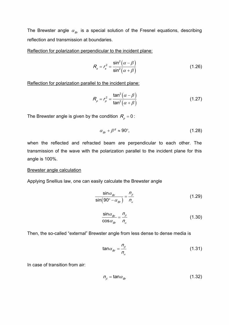
The Brewster angle Br
is a special solution of the Fresnel equations, describing
reflection and transmission at boundaries.
Reflection for polarization perpendicular to the incident plane:
2
2
2
sin
sins s
R r
(1.26)
Reflection for polarization parallel to the incident plane:
2
2
2
tan
tanp p
R r
(1.27)
The Brewster angle is given by the condition 0p
R :
90 ,g
Br (1.28)
when the reflected and refracted beam are perpendicular to each other. The
transmission of the wave with the polarization parallel to the incident plane for this
angle is 100%.
Brewster angle calculation
Applying Snellius law, one can easily calculate the Brewster angle
sin
sin 90
Br
Br
n
n
(1.29)
sin
cosBr
Br
n
n
(1.30)
Then, the so-called “external” Brewster angle from less dense to dense media is
tanBr
n
n
(1.31)
In case of transition from air:
tanBr
n
(1.32)

The angle dependence of the intensity reflection coefficients s
R and p
R for both
polarizations are shown in FIGURE 9.
FIGURE 9: Intensity reflection coefficients for the both polarizations in case of transition from air to plexiglass.
2.8. Birefringence and optical activity
Birefringent crystals have different refractive indices for different propagation direction.
Here, we deal only with the single axis birefringent crystals, which have to refractive
indices, namely no (ordinary) and neo (extraordinary).
FIGURE 10: Optical axis of a birefringent crystal.
Transmission in birefringent crystal cut parallel to optical axis
A plane wave, travelling through a birefringent crystal which is cut parallel to an optical
axis, shows a rotation of the polarization. This effect can be detected using two crossed
polarizers. Suppose, the incoming, unpolarized wave front consists of two wave fronts
with two mutually perpendicular polarization states ep
E and es
E . At the polarizer P
(FIGURE 11) the wave front with the polarization state es
E will be absorbed. The wave
different directions o eo
n n
optical axis o eo
n n

front after the polarizer P is linearly polarized. In case of the second polarizer is placed
perpendicular to the first one, the second wave front ep
E , and hence the transmission,
is completely blocked.
FIGURE 11: Transmission is blocked by two perpendicular aligned polarizers.
The birefringent crystal is placed between the polarizers with optical axes parallel to
the propagation direction. After the first polarizer, the linearly polarized wave front
propagates through the crystal. The polarization plane is rotated, and the second
polarizer does not block the light completely. After angle adjustment of the second
polarizer the rotation angle can be measured. The rotation angle depends on the
wavelength and thickness of the crystal. The optical activity is shown here with SiO2;
right- and left rotating crystals exist, depending on the crystal structure.
FIGURE 12: Linearly polarized wave propagates parallel to optical axis of a birefringent crystal. The polarization plane rotates during the propagation through the crystal.
cancellation of ep
E
cancellation of es
E
observer
Sense of rotation
for polarizer
optical axis