Embed Size (px)
Citation preview

TO PERFORMPASSION
CONTAMINATION CONTROL SOLUTIONS
MOBILE FILTRATION UNITS

1
A WORLDWIDE LEADER IN THE FIELD OF HYDRAULIC FILTRATION EQUIPMENT.
Our company started life in 1964, when Bruno Pasotto decided to attempt to cater for the requests of a market still to be fully explored, with the study, design, development, production and marketing of a vast range of fi lters for hydraulic equipment, capable of satisfying the needs of manufacturers in all sectors.The quality of our products, our extreme competitiveness compared with major international producers and our constant activities of research, design and development has made us a worldwide leader in the fi eld of hydraulic circuit fi ltering.Present for 50 years in the market, we have played a truly decisive role in defi ning our sector, and by now we are a group capable of controlling our entire chain of production, monitoringall manufacturing processes to guarantee superior quality standards and to provide concrete solutions for the rapidly evolvingneeds of customers and the market.

Our customer-oriented philosophy, which enables us to satisfy all customer requests rapidly and with personalized products, makes us a dynamic and fl exible enterprise.The possibility of constantly controlling and monitoring the entire production process is essential to allow us to guarantee the quality of our products.
Our work is based on a skillful interaction between advanced technology and fi ne workmanship, customizing products according to specifi c market requests, focusing strongly on innovation and quality, and following every step in the manufacturing of both standard and special products, fully respecting customer expectations.
Introduction 2
LEADERMARKET

USA
CANADAUNITED KINGDOM
FRANCE
ITALY
GERMANY
INDIA
RUSSIA
P.R. CHINA
WORLDWIDE PRESENCE
8The Group boasts business branches
Our foreign Branches enable us to offer a diversified range of products that allow us to successfully face the aggressive challenge of international competition, and also to maintain a stable presence at a local level.
Introduction3
Introduction 4
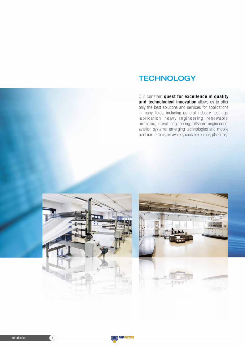
TECHNOLOGY
Our constant quest for excellence in quality and technological innovation allows us to offer only the best solutions and services for applications in many fields, including general industry, test rigs, l u b r i c a t i o n , h e a v y e ng i n e e r i n g, r e n ewab l e energ ies, nava l engineering, offshore engineering, aviation systems, emerging technologies and mobile plant (i.e. tractors, excavators, concrete pumps, platforms).
Introduction5
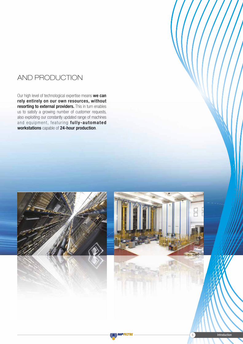
AND PRODUCTION
Our high level of technological expertise means we can rely entirely on our own resources, without resorting to external providers. This in turn enables us to satisfy a growing number of customer requests, also exploiting our constantly updated range of machines and equ ipmen t , f ea tu r i ng fu l ly-automated workstations capable of 24-hour production.
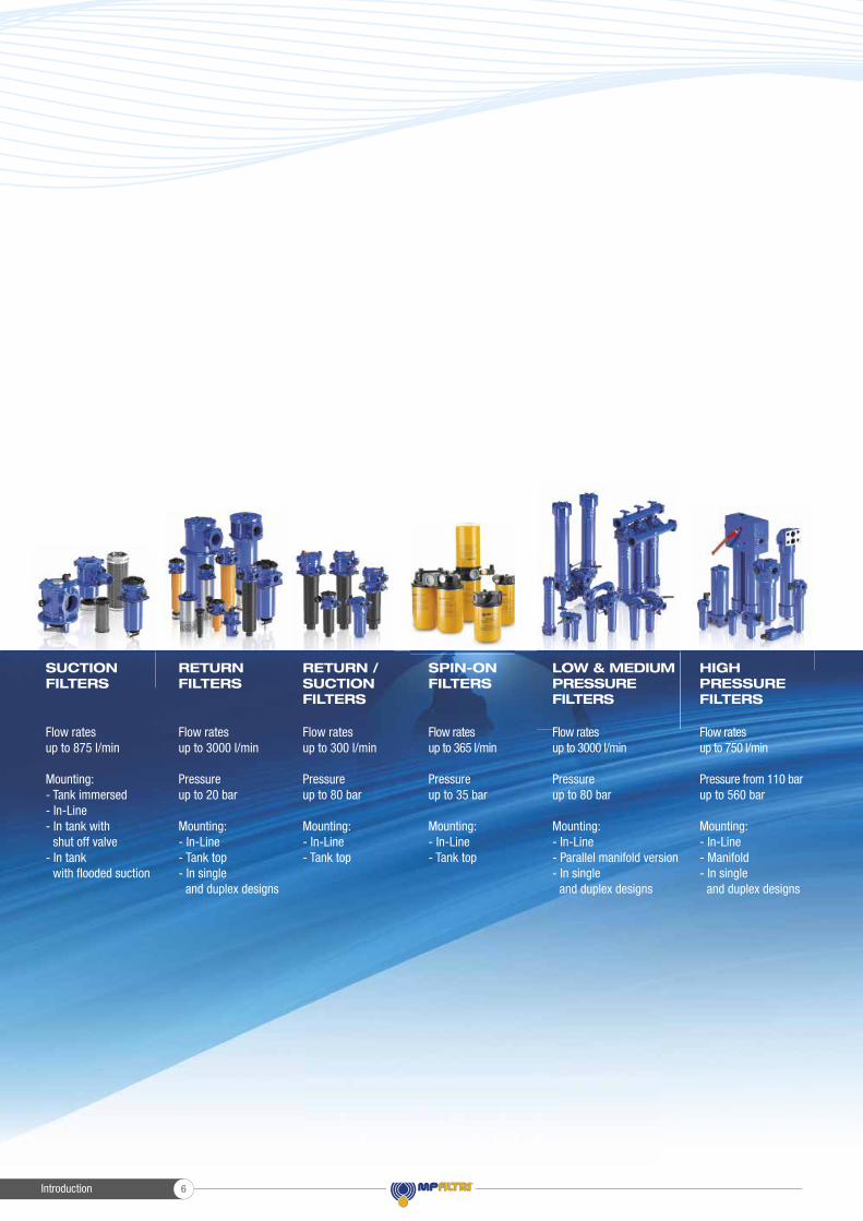
Flow rates up to 3000 l/min
Pressure up to 20 bar
Mounting:- In-Line- Tank top- In single and duplex designs
Flow rates up to 300 l/min
Pressure up to 80 bar
Mounting:- In-Line- Tank top
Flow rates up to 875 l/min
Mounting:- Tank immersed- In-Line- In tank with shut off valve- In tank with fl ooded suction
Flow rates up to 750 l/min
Pressure from 110 bar up to 560 bar
Mounting:- In-Line- Manifold- In single and duplex designs
Flow rates up to 3000 l/min
Pressure up to 80 bar
Mounting:- In-Line- Parallel manifold version- In single and duplex designs
LOW & MEDIUM PRESSURE FILTERS
HIGH PRESSURE FILTERS
SPIN-ON FILTERS
Flow rates up to 365 l/min
Pressure up to 35 bar
Mounting:- In-Line- Tank top
SUCTION FILTERS
RETURN FILTERS
RETURN /SUCTIONFILTERS
Introduction 6
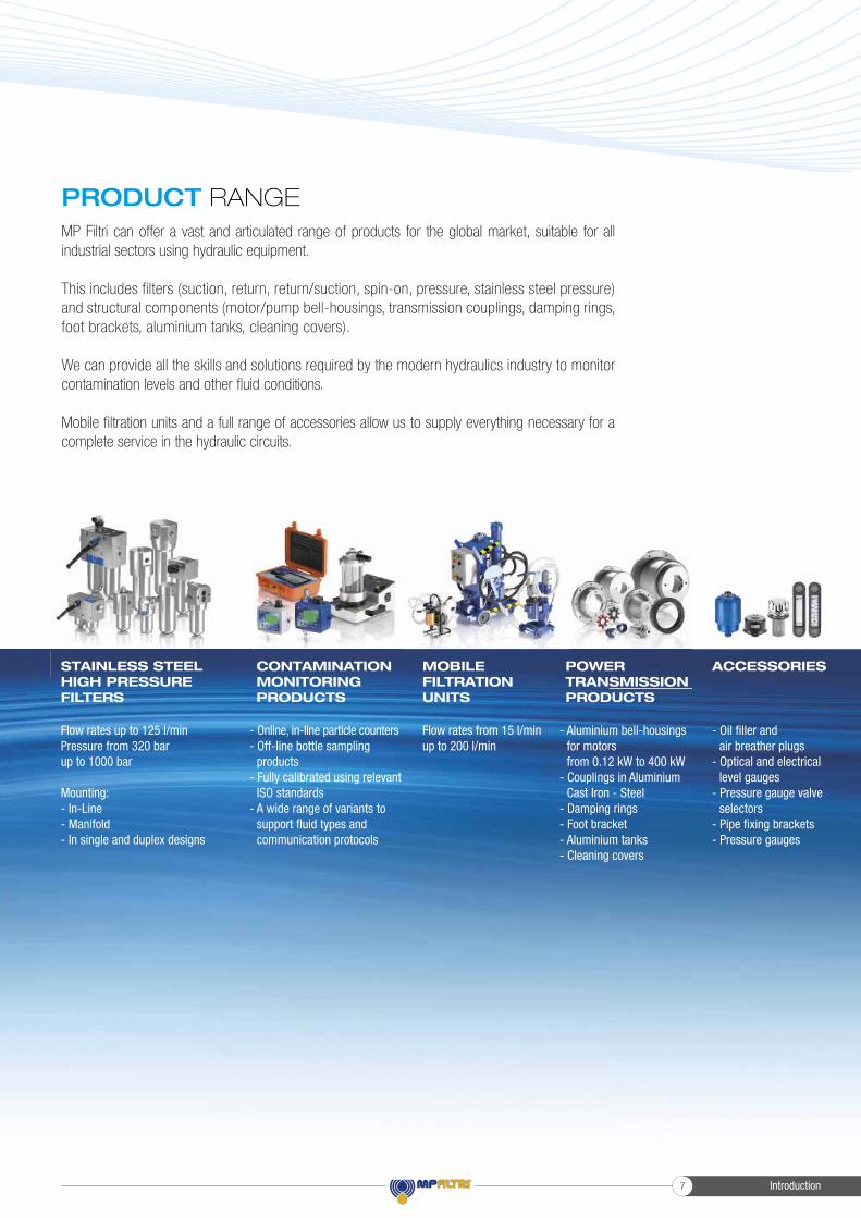
Flow rates up to 125 l/minPressure from 320 bar up to 1000 bar
Mounting:- In-Line- Manifold- In single and duplex designs
Flow rates from 15 l/min up to 200 l/min
MOBILE FILTRATION UNITS
- Oil fi ller and air breather plugs- Optical and electrical level gauges- Pressure gauge valve selectors- Pipe fi xing brackets- Pressure gauges
POWER TRANSMISSIONPRODUCTS
ACCESSORIESCONTAMINATION MONITORING PRODUCTS
STAINLESS STEEL HIGH PRESSURE FILTERS
- Aluminium bell-housings for motors from 0.12 kW to 400 kW- Couplings in Aluminium Cast Iron - Steel- Damping rings- Foot bracket- Aluminium tanks- Cleaning covers
- Online, in-line particle counters- Off-line bottle sampling products- Fully calibrated using relevant ISO standards- A wide range of variants to support fl uid types and communication protocols
Introduction7
PRODUCT RANGEMP Filtri can offer a vast and articulated range of products for the global market, suitable for all industrial sectors using hydraulic equipment.
This includes filters (suction, return, return/suction, spin-on, pressure, stainless steel pressure) and structural components (motor/pump bell-housings, transmission couplings, damping rings, foot brackets, aluminium tanks, cleaning covers).
We can provide all the skills and solutions required by the modern hydraulics industry to monitor contamination levels and other fl uid conditions.
Mobile fi ltration units and a full range of accessories allow us to supply everything necessary for a complete service in the hydraulic circuits.
CONTAMINATION CONTROL SOLUTIONS
...because contamination costs!
Introduction 8
INDEX
UFM 015
UFM 041
UFM 051
UFM 091
UFM 181
UFM 919
FTU 080
Mobile filtration unit 15 l/min flow rate
Mobile filtration unit 34 l/min flow rate
Mobile filtration unit 50 l/min flow rate
Mobile filtration unit 90 l/min flow rate
Mobile filtration unit 180 l/min flow rate
Mobile filtration unit 90 l/min and 180 l/min flow rate
Fluid transfer unit 15 l/min flow rate
MOBILE FILTRATION UNITS95
101
107
113
119
125
131
page92
COMPANY
PRODUCT RANGE
CONTAMINATION MANAGEMENT
INTRODUCTION1
6
11
page1
LPA3 Portable Particle Counter
LPA2 Twin Laser Particle Analyser
CML2 Compact Twin Laser Contamination Monitor
ICM 2.0 In-line Contamination Monitor
AZ2 ATEX Fluid Contamination Monitors
ICU In-line Contamination Monitoring Unit
ACMU Auxiliary Contamination Monitoring Unit
BS110 & BS500 Bottle Samplers
HOW SAMPLING
VPAF100 Patch test kit
FLUID COMPATIBILITY CHARTS
SPARE PARTS LIST
ACCESSORIES
AUTOMATIC PARTICLE COUNTERS21
27
33
39
45
51
57
63
72
75
78
81
83
page18
Introduction9

Introduction 10
HYDRAULIC FLUIDS
FLUIDS CONTAMINATION
EFFECTS OF CONTAMINATION ON HYDRAULIC COMPONENTS
MEASURING THE SOLID CONTAMINATION LEVEL
RECOMMENDED CONTAMINATION CLASSES
WATER IN HYDRAULIC AND LUBRICATING FLUIDS
12
12
12
13
16
16
Page
Contamination managementINDEX
Introduction
1
2
3
4
5
6
Introduction11
CONTAMINATION MANAGEMENT
HYDRAULIC FLUIDS
The fl uid is the vector that transmits power, energy within an oleodynamic circuit.In addition to transmitting energy through the circuit, it also performs additional functions such as lubrication, protection and cooling of the surfaces.The classifi cation of fl uids used in hydraulic systems is coded in many regulatory references, different Standards.
The most popular classifi cation criterion divides them into the following families:- MINERAL OILS Commonly used oil deriving fl uids.
- FIRE RESISTANT FLUIDS Fluids with intrinsic characteristics of incombustibility or high fl ash point.
- SYNTHETIC FLUIDS Modifi ed chemical products to obtain specifi c optimized features.
- ECOLOGICAL FLUIDS Synthetic or vegetable origin fl uids with high biodegradability characteristics.
The choice of fl uid for an hydraulic system must take into account several parameters.These parameters can adversely affect the performance of an hydraulic system, causing delay in the controls, pump cavitation, excessive absorption, excessive temperature rise, effi ciency reduction, increased drainage, wear, jam/block or air intake in the plant.
The main properties that characterize hydraulic fl uids and affect their choice are:- DYNAMIC VISCOSITY It identifi es the fl uid’s resistance to sliding due to the impact of the particles forming it.
- CINEMATIC VISCOSITY It is a widespread formal dimension in the hydraulic fi eld. It is calculated with the ratio between the dynamic viscosity and the fluid density. Cinematic viscosity varies with temperature and pressure variations.
- VISCOSITY INDEX This value expresses the ability of a fluid to maintain viscosity when the temperature changes. A high viscosity index indicates the fluid’s ability to limit viscosity variations by varying the temperature.
- FILTERABILITY INDEX It is the value that indicates the ability of a fluid to cross the filter materials. A low fi lterability index could cause premature clogging of the fi lter material.
- WORKING TEMPERATURE Working temperature affects the fundamental characteristics of the fluid. As already seen, some fl uid characteristics, such as cinematic viscosity, vary with the temperature variation. When choosing a hydraulic oil, must therefore be taken into account of the environmental conditions in which the machine will operate.
- COMPRESSIBILITY MODULE Every fl uid subjected to a pressure contracts, increasing its density. The compressibility module identifies the increase in pressure required to cause a corresponding increase in density.
- HYDROLYTIC STABILITY It is the characteristic that prevents galvanic pairs that can cause wear in the plant/system.
- ANTIOXIDANT STABILITY AND WEAR PROTECTION These features translate into the capacity of a hydraulic oil to avoid corrosion of metal elements inside the system.
- HEAT TRANSFER CAPACITY It is the characteristic that indicates the capacity of hydraulic oil to exchange heat with the surfaces and then cool them.
FLUID CONTAMINATION
Whatever the nature and properties of fluids, they are inevitably subject to contamination. Fluid contamination can have two origins:
- INITIAL CONTAMINATION Caused by the introduction of contaminated fl uid into the circuit, or by incorrect storage, transport or transfer operations.
- PROGRESSIVE CONTAMINATION Caused by factors related to the operation of the system, such as metal surface wear, sealing wear, oxidation or degradation of the fluid, the introduction of contaminants during maintenance, corrosion due to chemical or electrochemical action between fluid and components, cavitation. The contamination of hydraulic systems can be of different nature:
- SOLID CONTAMINATION For example rust, slag, metal particles, fi bers, rubber particles, paint particles - or additives
- LIQUID CONTAMINATION For example, the presence of water due to condensation or external infi ltration or acids
- GASEOUS CONTAMINATION For example, the presence of air due to inadequate oil level in the tank, drainage in suction ducts, incorrect sizing of tubes or tanks.
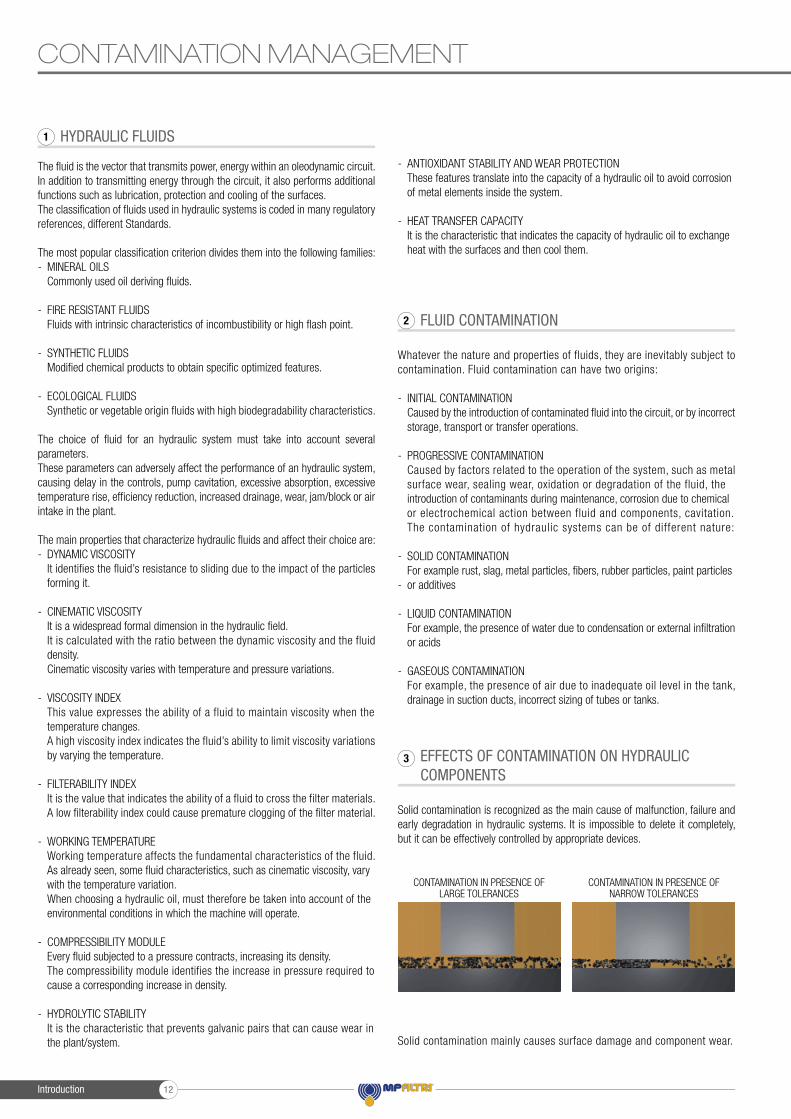
EFFECTS OF CONTAMINATION ON HYDRAULIC COMPONENTS
Solid contamination is recognized as the main cause of malfunction, failure and early degradation in hydraulic systems. It is impossible to delete it completely, but it can be effectively controlled by appropriate devices.
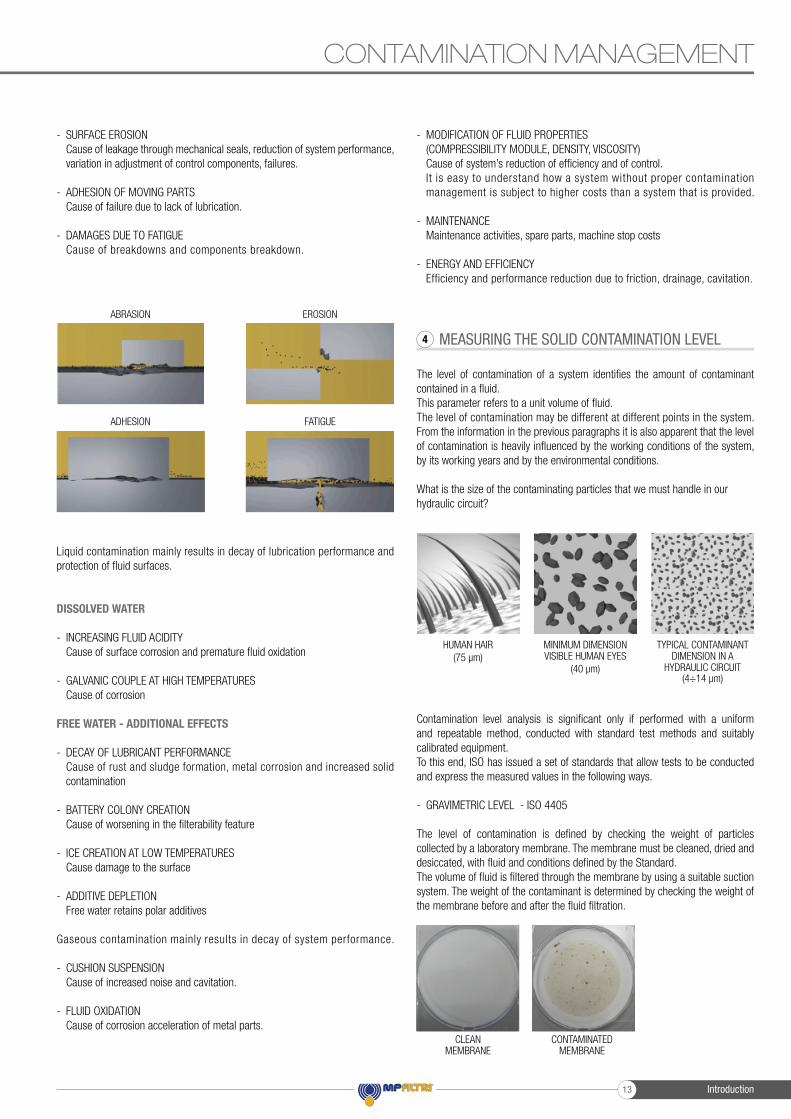
Solid contamination mainly causes surface damage and component wear.
EFFECTS OF CONTAMINATION ON HYDRAULIC 3
CONTAMINATION IN PRESENCE OF LARGE TOLERANCES
CONTAMINATION IN PRESENCE OF NARROW TOLERANCES
FLUID CONTAMINATION2
HYDRAULIC FLUIDS1
Introduction 12
CONTAMINATION MANAGEMENT
- SURFACE EROSION Cause of leakage through mechanical seals, reduction of system performance, variation in adjustment of control components, failures.
- ADHESION OF MOVING PARTS Cause of failure due to lack of lubrication.
- DAMAGES DUE TO FATIGUE Cause of breakdowns and components breakdown.
Liquid contamination mainly results in decay of lubrication performance and protection of fl uid surfaces.
DISSOLVED WATER
- INCREASING FLUID ACIDITY Cause of surface corrosion and premature fl uid oxidation
- GALVANIC COUPLE AT HIGH TEMPERATURES Cause of corrosion
FREE WATER - ADDITIONAL EFFECTS
- DECAY OF LUBRICANT PERFORMANCE Cause of rust and sludge formation, metal corrosion and increased solid contamination
- BATTERY COLONY CREATION Cause of worsening in the fi lterability feature
- ICE CREATION AT LOW TEMPERATURES Cause damage to the surface
- ADDITIVE DEPLETION Free water retains polar additives
Gaseous contamination mainly results in decay of system performance.
- CUSHION SUSPENSION Cause of increased noise and cavitation.
- FLUID OXIDATION Cause of corrosion acceleration of metal parts.
- MODIFICATION OF FLUID PROPERTIES (COMPRESSIBILITY MODULE, DENSITY, VISCOSITY) Cause of system’s reduction of effi ciency and of control. It is easy to understand how a system without proper contamination management is subject to higher costs than a system that is provided.
- MAINTENANCE Maintenance activities, spare parts, machine stop costs
- ENERGY AND EFFICIENCY Efficiency and performance reduction due to friction, drainage, cavitation.
MEASURING THE SOLID CONTAMINATION LEVEL
The level of contamination of a system identifi es the amount of contaminant contained in a fl uid.This parameter refers to a unit volume of fl uid.The level of contamination may be different at different points in the system.From the information in the previous paragraphs it is also apparent that the level of contamination is heavily infl uenced by the working conditions of the system, by its working years and by the environmental conditions.
What is the size of the contaminating particles that we must handle in our hydraulic circuit?
Contamination level analysis is signifi cant only if performed with a uniform and repeatable method, conducted with standard test methods and suitably calibrated equipment.To this end, ISO has issued a set of standards that allow tests to be conducted and express the measured values in the following ways.
- GRAVIMETRIC LEVEL - ISO 4405
The level of contamination is defi ned by checking the weight of particles collected by a laboratory membrane. The membrane must be cleaned, dried and desiccated, with fl uid and conditions defi ned by the Standard.The volume of fl uid is fi ltered through the membrane by using a suitable suction system. The weight of the contaminant is determined by checking the weight of the membrane before and after the fl uid fi ltration.
HUMAN HAIR(75 µm)
MINIMUM DIMENSION VISIBLE HUMAN EYES
(40 µm)
TYPICAL CONTAMINANT DIMENSION IN A
HYDRAULIC CIRCUIT(4÷14 µm)
MEASURING THE SOLID CONTAMINATION LEVEL4
ABRASION
ADHESION
EROSION
FATIGUE
CLEAN MEMBRANE
CONTAMINATED MEMBRANE
Introduction13
CONTAMINATION MANAGEMENT
- CUMULATIVE DISTRIBUTION OF THE PARTICLES SIZE - ISO 4406
The level of contamination is defined by counting the number of particles of certain dimensions per unit of volume of fluid. Measurement is performed by Automatic Particle Counters (APC).Following the count, the contamination classes are determined, corresponding to the number of particles detected in the unit of fluid.The most common classification methods follow ISO 4406 and SAE AS 4059 (Aerospace Sector) regulations.NAS 1638 is still used although obsolete.
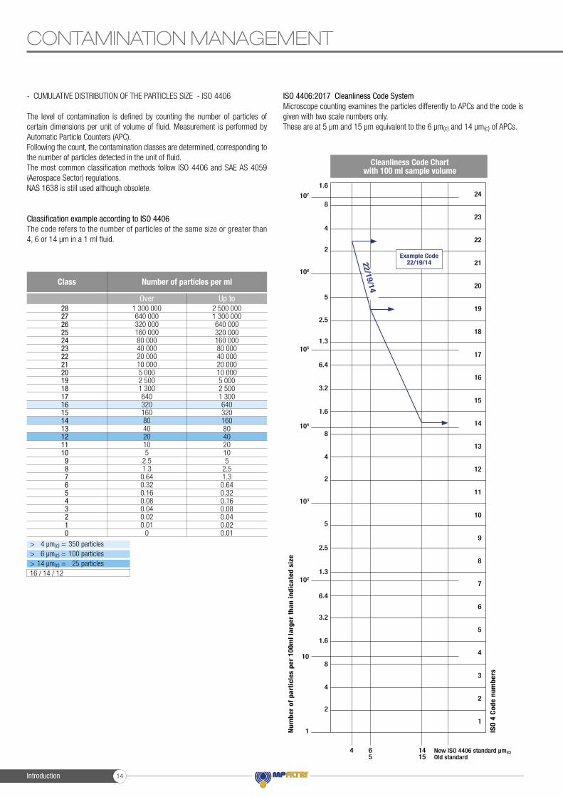
Classification example according to ISO 4406The code refers to the number of particles of the same size or greater than 4, 6 or 14 μm in a 1 ml fluid.
ISO 4406:2017 Cleanliness Code SystemMicroscope counting examines the particles differently to APCs and the code is given with two scale numbers only.These are at 5 µm and 15 µm equivalent to the 6 µm(c) and 14 µm(c) of APCs.
Num
ber
of p
arti
cles
per
100
ml l
arge
r th
an in
dica
ted
size
Cleanliness Code Chart with 100 ml sample volume
24
23
22
21
20
19
18
17
16
15
14
13
12
11
10
9
8
7
6
5
4
3
2
1
1.6
8
8
8
4
4
4
4 65
1415
New ISO 4406 standard µm(c) Old standard
ISO
4 C
ode
num
bers
2
2
2
1
10
102
103
104
105
106
107
5
5
6.4
6.4
2.5
2.5
3.2
3.2
1.3
1.3
1.6
1.6
Example Code22/19/1422/19/14
> 4 µm(c) = 350 particles> 6 µm(c) = 100 particles> 14 µm(c) = 25 particles16 / 14 / 12
1 300 000640 000320 000160 00080 00040 00020 00010 0005 0002 5001 300640320160804020105
2.51.30.640.320.160.080.040.020.01
0
2 500 0001 300 000640 000320 000160 00080 00040 00020 00010 0005 0002 5001 300640320160804020105
2.51.30.640.320.160.080.040.020.01
282726252423222120191817161514131211109876543210
Class Number of particles per ml
Over Up to
Introduction 14
- CUMULATIVE DISTRIBUTION OF THE PARTICLES SIZE - SAE AS 4059-1 and SAE AS 4059-2
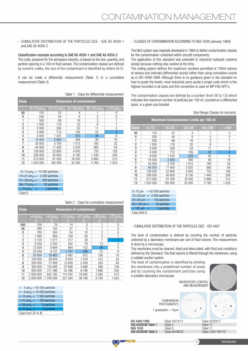
Classification example according to SAE AS 4059-1 and SAE AS 4059-2The code, prepared for the aerospace industry, is based on the size, quantity, and particle spacing in a 100 ml fluid sample. The contamination classes are defined by numeric codes, the size of the contaminant is identified by letters (A-F).
It can be made a differential measurement (Table 1) or a cumulative measurement (Table 2)
- CLASSES OF CONTAMINATION ACCORDING TO NAS 1638 (January 1964)
The NAS system was originally developed in 1964 to define contamination classes for the contamination contained within aircraft components. The application of this standard was extended to industrial hydraulic systems simply because nothing else existed at the time.The coding system defines the maximum numbers permitted of 100ml volume at various size intervals (differential counts) rather than using cumulative counts as in ISO 4406:1999. Although there is no guidance given in the standard on how to quote the levels, most industrial users quote a single code which is thehighest recorded in all sizes and this convention is used on MP Filtri APC’s.
The contamination classes are defined by a number (from 00 to 12) which indicates the maximum number of particles per 100 ml, counted on a differential basis, in a given size bracket.
- CUMULATIVE DISTRIBUTION OF THE PARTICLES SIZE - ISO 4407
The level of contamination is defined by counting the number of particles collected by a laboratory membrane per unit of fluid volume. The measurement is done by a microscope.The membrane must be cleaned, dried and desiccated, with fluid and conditions defined by the Standard. The fluid volume is filtered through the membrane, using a suitable suction system.The level of contamination is identified by dividing the membrane into a predefined number of areas and by counting the contaminant particles using a suitable laboratory microscope.
CONTAMINATION MANAGEMENT
195390780
1 5603 1206 250
12 50025 00050 000
100 000200 000400 000800 000
1 600 0003 200 000
76152304609
1 2172 4324 8649 731
19 46238 92477 849
155 698311 396622 792
1 245 584
142754
109217432864
1 7313 4626 924
13 84927 69855 396
110 792221 584
35
10203976
152306612
1 2242 4494 8989 796
19 59239 184
11247
132653
106212424848
1 6963 3926 784
00011248
163264
128256512
1 024
000000123456789101112
Class Dimension of contaminant
>4 µm(c)A
>6 µm(c)B
>14 µm(c)C
>21 µm(c)D
>38 µm(c)E
>70 µm(c)F
Table 2 - Class for cumulative measurement
125250500
1 0002 0004 0008 000
16 00032 00064 000
128 000256 000512 000
1 024 000
224489
178356712
1 4252 8505 700
11 40022 80045 60091 200
182 400
48
163263
126253506
1 0122 0254 0508 100
16 20032 400
1236
11224590
180360720
1 4402 8805 760
0011248
163264
128256512
1 024
000123456789101112
Class Dimension of contaminant
6÷14 µm(c) 14÷21 µm(c) 21÷38 µm(c) 38÷70 µm(c) >70 µm(c)
Table 1 - Class for differential measurement
6÷14 µm(c) = 15 000 particles14÷21 µm(c) = 2 200 particles21÷38 µm(c) = 200 particles38÷70 µm(c) = 35 particles> 70 µm(c) = 3 particlesClass 6
Size Range Classes (in microns)
Maximum Contamination Limits per 100 ml
000123456789
101112
125250500
1 0002 0004 0008 000
16 00032 00064 000
128 000256 000512 000
1 024 000
224489
178356712
1 4252 8505 700
11 40022 80045 60091 200
182 400
48
163263
126253506
1 0122 0254 0508 100
16 20032 400
1236
11224590
180360720
1 4402 8805 760
0011248
163264
128256512
1 024
5÷15 15÷25 25÷50 50÷100 >100Class
MICROSCOPE CONTROL AND MEASUREMENT
COMPARISON PHOTOGRAPH’S
ISO 4406:1999SAE AS4059E Table 1NAS 1638SAE AS4059E Table 2
Class 16/14/11Class 5Class 5Class 6A/5B/5C
Class 22/20/17Class 11Class 11Class 12A/11B/11C
1 graduation = 10µm
> 4 µm(c) = 45 000 particles> 6 µm(c) = 15 000 particles> 14 µm(c) = 1 500 particles> 21 µm(c) = 250 particles> 38 µm(c) = 15 particles> 70 µm(c) = 3 particlesClass from 2F to 4E
=====
42 000 particles2 200 particles
150 particles18 particles3 particles
5÷15 µm15÷25 µm 25÷50 µm50÷100 µm> 100 µmClass NAS 8
Introduction15
CONTAMINATION MANAGEMENT
- CLEANLINESS CODE COMPARISON
Although ISO 4406:2017 standard is being used extensively within the hydraulics industry other standards are occasionally required and a comparison may be requested. The table below gives a very general comparison but often no direct comparison is possible due to the different classes and sizes involved.
RECOMMENDED CONTAMINATION CLASSES
Any are the nature and the properties of fl uids, they are inevitably subject to contamination. The level of contamination can be managed by using special components called fi lters.Hydraulic components builders, knowing the problem of contamination, recommend the fi ltration level appropriate to the use of their products.
Example of recommended contamination levels for pressures below 140 bar.
WATER IN HYDRAULIC AND LUBRICATING FLUIDS
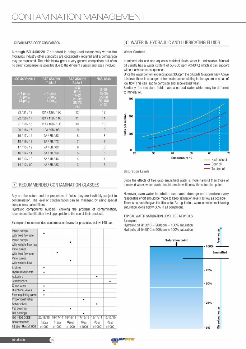
Water Content
In mineral oils and non aqueous resistant fl uids water is undesirable. Mineral oil usually has a water content of 50-300 ppm (@40°C) which it can support without adverse consequences.Once the water content exceeds about 300ppm the oil starts to appear hazy. Above this level there is a danger of free water accumulating in the system in areas of low fl ow. This can lead to corrosion and accelerated wear.Similarly, fire resistant fluids have a natural water which may be different to mineral oil.
Saturation Levels
Since the effects of free (also emulsifi ed) water is more harmful than those of dissolved water, water levels should remain well below the saturation point.
However, even water in solution can cause damage and therefore every reasonable effort should be made to keep saturation levels as low as possible.There is no such thing as too little water. As a guideline, we recommend maintaining saturation levels below 50% in all equipment.
TYPICAL WATER SATURATION LEVEL FOR NEW OILSExamples:Hydraulic oil @ 30°C = 200ppm = 100% saturationHydraulic oil @ 65°C = 500ppm = 100% saturation
RECOMMENDED CONTAMINATION CLASSES5
6
23 / 21 / 18
22 / 20 / 17
21 / 19 / 16
20 / 18 / 15
19 / 17 / 14
18 / 16 / 13
17 / 15 / 12
16 / 14 / 11
15 / 13 / 10
14 / 12 / 09
13A / 12B / 12C
12A / 11B / 11C
11A / 10B / 10C
10A / 9B / 9B
9A / 8B / 8C
8A / 7B / 7C
7A / 6B / 6C
6A / 5B / 5C
5A / 4B / 4C
4A / 3B / 3C
12
11
10
9
8
7
6
5
4
3
12
11
10
9
8
7
6
5
4
3
ISO 4406:2017 SAE AS4059Table 2
SAE AS4059Table 1
NAS 1638
> 4 µm(c)6 µm(c)
14 µm(c)
> 4 µm(c)6 µm(c)
14 µm(c)
4-6 6-14
14-21 21-38 38-70 >70
5-1515-2525-50
50-100>100
Part
s pe
r m
illio
n
Temperature °C
20
200
400
600
030 40 50 60 70
Hydraulic oilGear oilTurbine oil
Saturation point
Emulsified
Dis
solv
ed w
ater
Free
wat
er
- 0%
- 25%
- 50%
- 75%
- 100%
Piston pumps with fi xed fl ow ratePiston pumps with variable fl ow rateVane pumps with fi xed fl ow rateVane pumps with variable fl owEnginesHydraulic cylindersActuatorsTest benchesCheck valveDirectional valvesFlow regulating valvesProportional valvesServo-valvesFlat bearingsBall bearingsISO 4406 CODERecommended fi ltration ßx(c)≥1.000
•
•
•
•
••
••
•
•
•
•
•••
20/18/15ß20(c)
>1000
17/15/12ß7(c)
>1000
19/17/14ß15(c)
>1000
16/14/11ß7(c)
>1000
18/16/13ß10(c)
>1000
15/13/10ß5(c)
>1000
Introduction 16
W - Water and Temperature Sensing
“W” option, in MP Filtri Contamination Monitoring Products, indicates water content as a percentage of saturation and oil temperature in degrees centigrade. 100% RH corresponds to the point at which free water can exist in the fluid. i.e. the fluid is no longer able to hold the water in a dissolved solution.The sensor can help provide early indication of costly failure due to free water, including but not exclusive to:- Corrosion- Metal surface fatigue e.g. bearing failure- Reduced lubrication & load carrying characteristics
Different oils have different saturation levels and therefore RH (relative humidity) % is the best and most practical measurement.
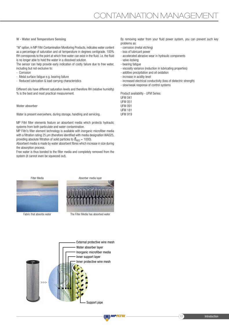
Water absorber
Water is present everywhere, during storage, handling and servicing.
MP Filtri filter elements feature an absorbent media which protects hydraulic systems from both particulate and water contamination.MP Filtri’s filter element technology is available with inorganic microfiber media with a filtration rating 25 μm (therefore identified with media designation WA025, providing absolute filtration of solid particles to ßx(c) = 1000).Absorbent media is made by water absorbent fibres which increase in size during the absorption process.Free water is thus bonded to the filter media and completely removed from the system (it cannot even be squeezed out).
By removing water from your fluid power system, you can prevent such key problems as:- corrosion (metal etching)- loss of lubricant power- accelerated abrasive wear in hydraulic components- valve-locking- bearing fatigue- viscosity variance (reduction in lubricating properties)- additive precipitation and oil oxidation- increase in acidity level- increased electrical conductivity (loss of dielectric strength)- slow/weak response of control systems
Product availability - UFM Series:UFM 041UFM 051UFM 091UFM 181UFM 919
CONTAMINATION MANAGEMENT
Filter Media Absorber media layer
Fabric that absorbs water The Filter Media has absorbed water
>>>
External protective wire mesh
Water absorber layerInorganic microfiber mediaInner support layerInner protective wire mesh
Support pipe
Introduction17
Filtered to perfectionOur mobile filtration units provide the perfect solution for the oil maintenance of your lubrication and hydraulic fluids in off-line filtration applications.
Benefits:- Versatile and compact design- Filtering and continuous cleaning of systems- Removal of water from hydraulic systems (when fitted with a spin on filter)- Particle counting to determine the Contamination Class according to ISO4406, NAS1638, AS4059
Applications:- For oil changes, initial filling and flushing cycles in hydraulic and lubrication systems- Pulp and paper mill equipment- Construction machinery- Large central hydraulic power units- Injection moulding equipment- Stamping presses
Mobile filtration units 92

Mobile fi ltration units
UFM 015
UFM 041
UFM 051
UFM 091
UFM 181
UFM 919
FTU 080
95
101
107
113
119
125
131
page
UFM 041 UFM 051
UFM 091-181-919 FTU
UFM 015
UFM 091-181-919
Mobile fi ltration units93

Mobile filtration units 94

Mobile fi ltration unit 15 l/min fl ow rate
Mobile fi ltration units
UFM 015
Mobile fi ltration units95
UFM 015 GENERAL INFORMATION
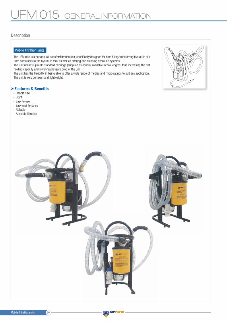
The UFM 015 is a portable oil transfer/fi ltration unit, specifi cally designed for both fi lling/transferring hydraulic oils from containers to the hydraulic tank as well as fi ltering and cleaning hydraulic systems.The unit utilises Spin-On standard cartridge (supplied as option), available in two lengths, thus increasing the dirt holding capacity and lowering pressure drop of the unit.The unit has the fl exibility in being able to offer a wide range of medias and micro ratings to suit any application.The unit is very compact and lightweight.
Description
Mobile fi ltration units
Features & Benefi ts- Handle size- Light- Easy to use- Easy maintenance- Reliable- Absolute fi ltration
>
Mobile fi ltration units 96
UFM 015GENERAL INFORMATION
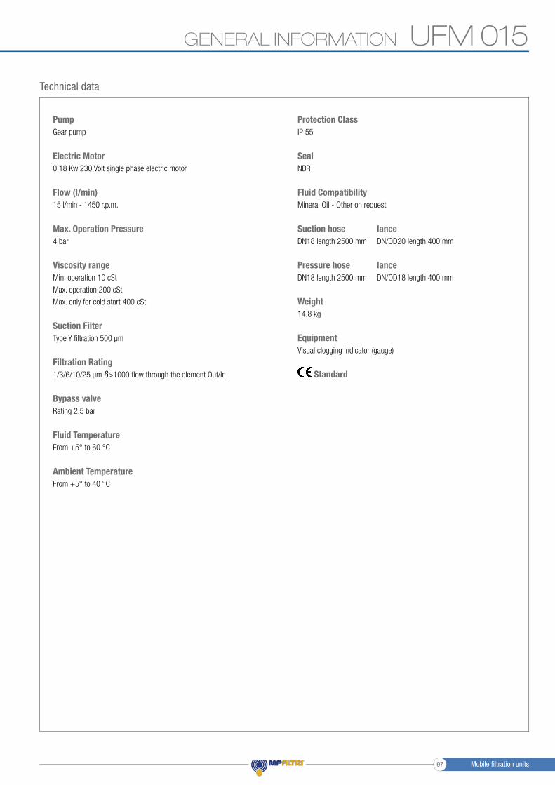
Technical data
PumpGear pump
Electric Motor0.18 Kw 230 Volt single phase electric motor
Flow (l/min)15 l/min - 1450 r.p.m.
Max. Operation Pressure4 bar
Viscosity rangeMin. operation 10 cSt
Max. operation 200 cSt
Max. only for cold start 400 cSt
Suction FilterType Y fi ltration 500 μm
Filtration Rating1/3/6/10/25 μm ß>1000 fl ow through the element Out/In
Bypass valveRating 2.5 bar
Fluid TemperatureFrom +5° to 60 °C
Ambient TemperatureFrom +5° to 40 °C
Protection ClassIP 55
SealNBR
Fluid CompatibilityMineral Oil - Other on request
Suction hose lanceDN18 length 2500 mm DN/OD20 length 400 mm
Pressure hose lanceDN18 length 2500 mm DN/OD18 length 400 mm
Weight14.8 kg
EquipmentVisual clogging indicator (gauge)
Standard
Mobile fi ltration units97
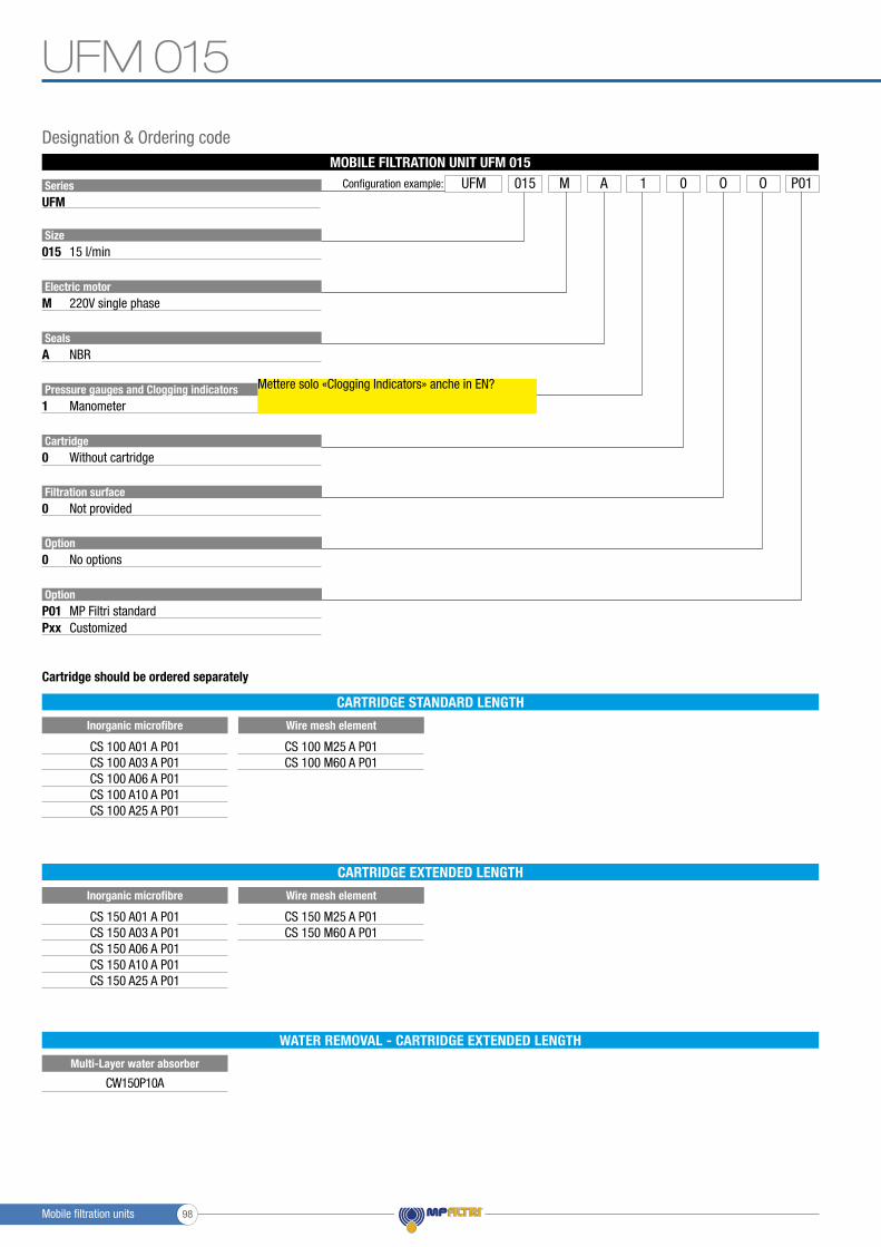
MOBILE FILTRATION UNIT UFM 015
SeriesUFM
Size
Pressure gauges and Clogging indicators
Cartridge
Filtration surface
Option
Electric motor
Seals
015
1
0
0
M
P01
A
Pxx
15 l/min
Cartridge should be ordered separately
Manometer
Without cartridge
Not provided
Option0 No options
220V single phase
MP Filtri standard
NBR
Customized
Configuration example: UFM A P010015 M 1 OO
Designation & Ordering code
CS 100 A01 A P01CS 100 A03 A P01CS 100 A06 A P01CS 100 A10 A P01CS 100 A25 A P01
CS 150 A01 A P01CS 150 A03 A P01CS 150 A06 A P01CS 150 A10 A P01CS 150 A25 A P01
CS 100 M25 A P01CS 100 M60 A P01
CS 150 M25 A P01CS 150 M60 A P01
Inorganic microfibre
Inorganic microfibre
Multi-Layer water absorber
Wire mesh element
Wire mesh element
CARTRIDGE STANDARD LENGTH
CARTRIDGE EXTENDED LENGTH
WATER REMOVAL - CARTRIDGE EXTENDED LENGTH
CW150P10A
UFM 015
Mobile filtration units 98
Mettere solo «Clogging Indicators» anche in EN?
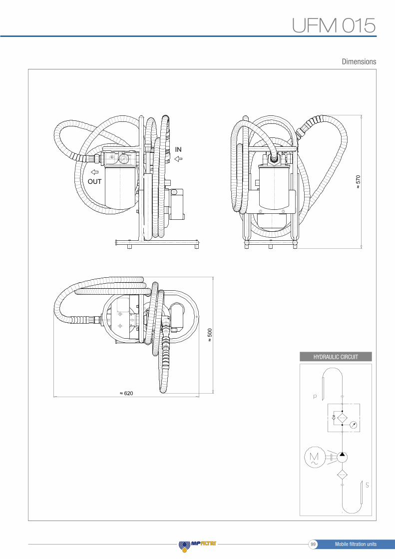
Dimensions
ARIA 620
HYDRAULIC CIRCUIT
UFM 015
Mobile filtration units99

Mobile filtration units 100

Mobile fi ltration units
UFM 041Mobile fi ltration unit 34 l/min fl ow rate
Mobile fi ltration units101

UFM 041 GENERAL INFORMATION
Mobile fi ltration units
UFM 041 mobile fi ltration units suitable for fi lling and refi lling of fi ltered hydraulic fl uids and lubrication tanks.
The fi lter unit connected to off-line to the tank (recommended maximum volume of 350/500 L.), can be used as a support to the fi ltration plant on start-up for fast fl ushing action, either as additional fi ltration systems with a high incidence of contamination.
Continued use is recommended for the version with three phase electric motor.
Description
Features & Benefi ts- Compact size- Light- Easy to use- Easy maintenance- Reliable- Absolute fi ltration
>
Mobile fi ltration units 102
UFM 041GENERAL INFORMATION
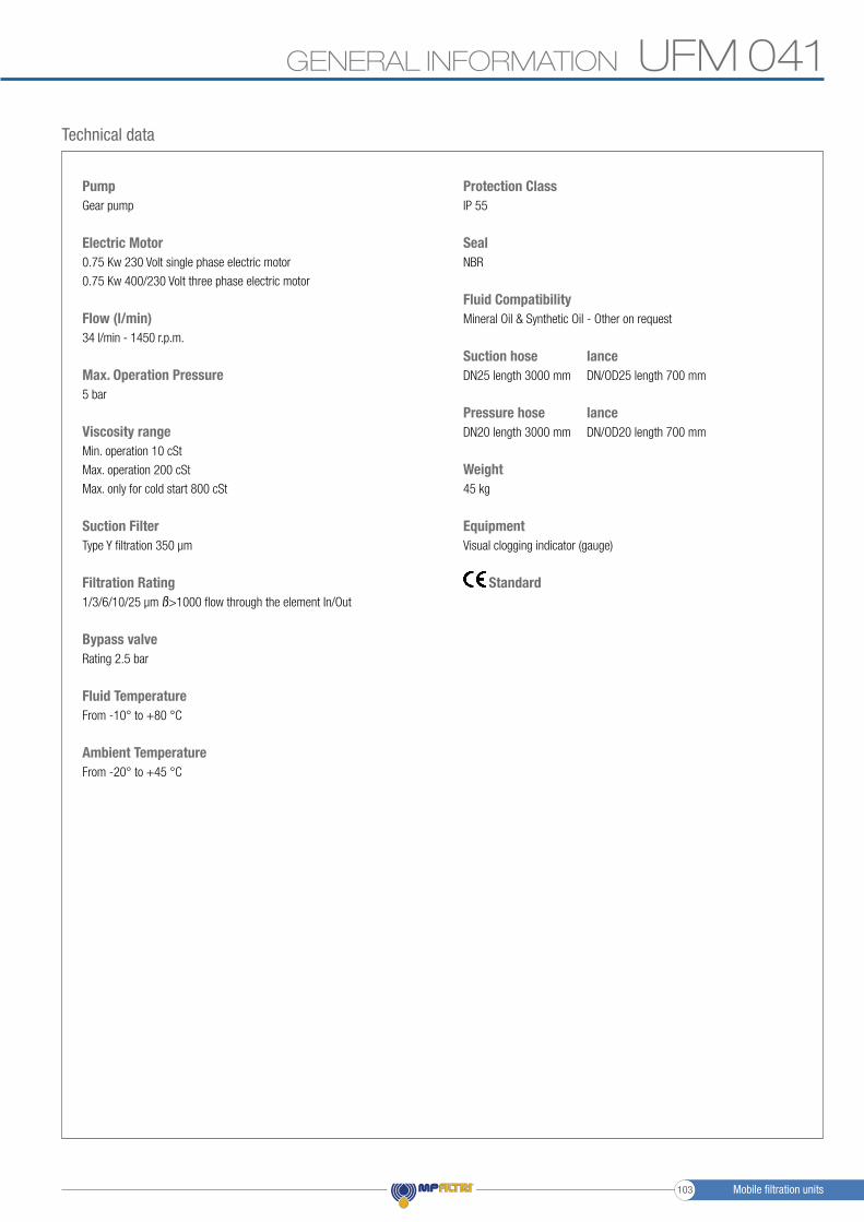
Technical data
PumpGear pump
Electric Motor0.75 Kw 230 Volt single phase electric motor
0.75 Kw 400/230 Volt three phase electric motor
Flow (l/min)34 l/min - 1450 r.p.m.
Max. Operation Pressure5 bar
Viscosity rangeMin. operation 10 cSt
Max. operation 200 cSt
Max. only for cold start 800 cSt
Suction FilterType Y filtration 350 μm
Filtration Rating1/3/6/10/25 μm ß>1000 flow through the element In/Out
Bypass valveRating 2.5 bar
Fluid TemperatureFrom -10° to +80 °C
Ambient TemperatureFrom -20° to +45 °C
Protection ClassIP 55
SealNBR
Fluid CompatibilityMineral Oil & Synthetic Oil - Other on request
Suction hose lanceDN25 length 3000 mm DN/OD25 length 700 mm
Pressure hose lanceDN20 length 3000 mm DN/OD20 length 700 mm
Weight 45 kg
EquipmentVisual clogging indicator (gauge)
Standard
Mobile filtration units103
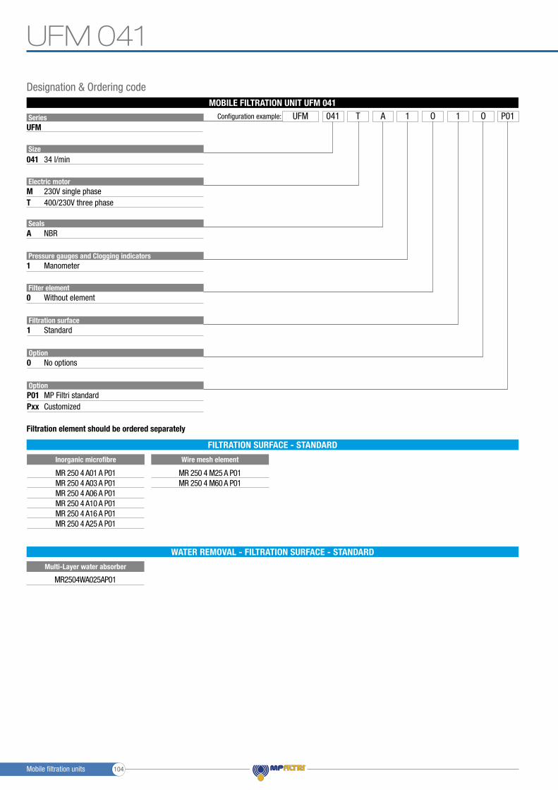
SeriesUFM
Size
Pressure gauges and Clogging indicators
Electric motor
Seals
041
1
M
A
T
34 l/min
Filter element0 Without element
Manometer
230V single phase
NBR
400/230V three phase
Configuration example: UFM A 1 P011041 T O O
MR 250 4 A01 A P01MR 250 4 A03 A P01MR 250 4 A06 A P01MR 250 4 A10 A P01MR 250 4 A16 A P01MR 250 4 A25 A P01
MR 250 4 M25 A P01MR 250 4 M60 A P01
Inorganic microfibre Wire mesh element
Filtration surface
Option
1
P01Pxx
Standard
Option0 No options
MP Filtri standardCustomized
MOBILE FILTRATION UNIT UFM 041
Filtration element should be ordered separately
Designation & Ordering code
FILTRATION SURFACE - STANDARD
Multi-Layer water absorber
WATER REMOVAL - FILTRATION SURFACE - STANDARD
MR2504WA025AP01
UFM 041
Mobile filtration units 104
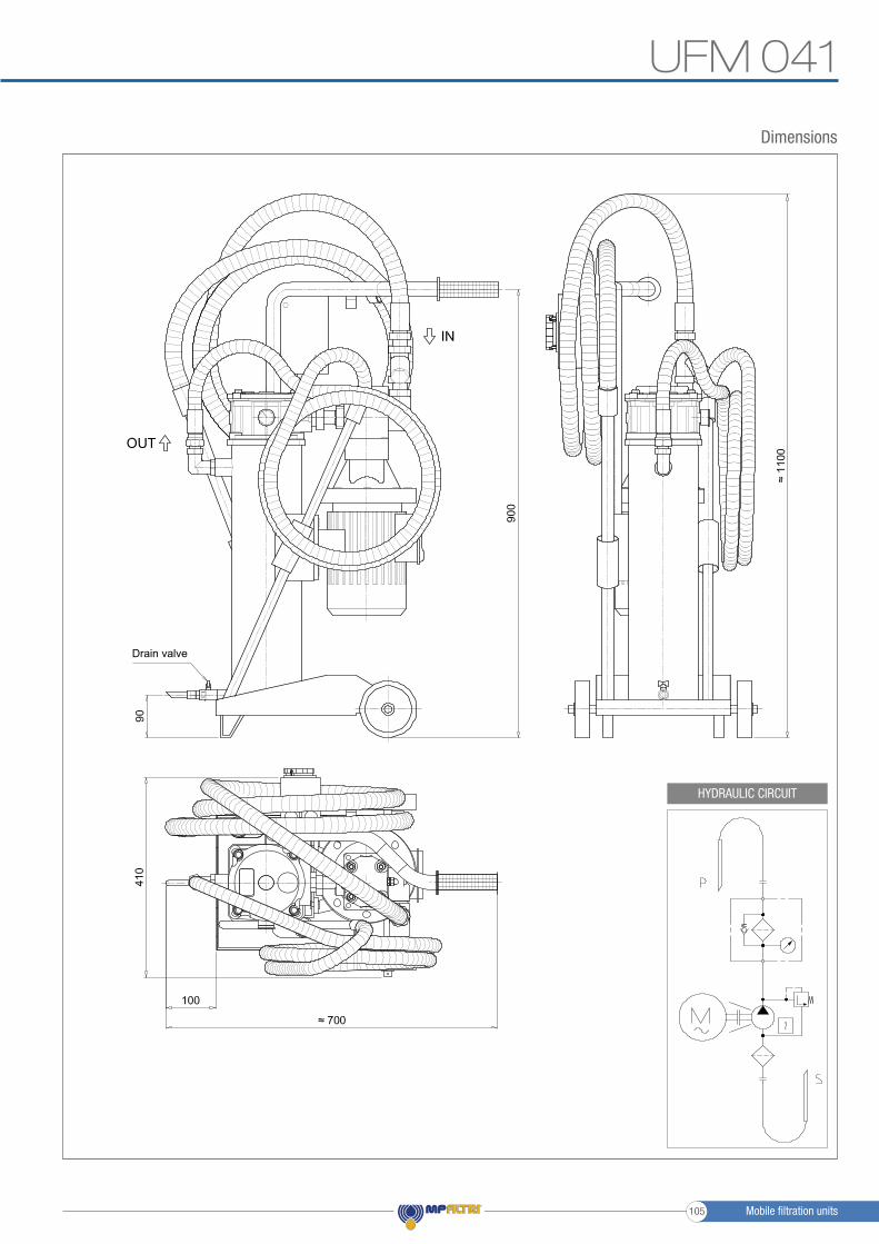
Dimensions
HYDRAULIC CIRCUIT
UFM 041
ARIA 620
Drain valve
Mobile filtration units105

Mobile filtration units 106
Mobile fi ltration units
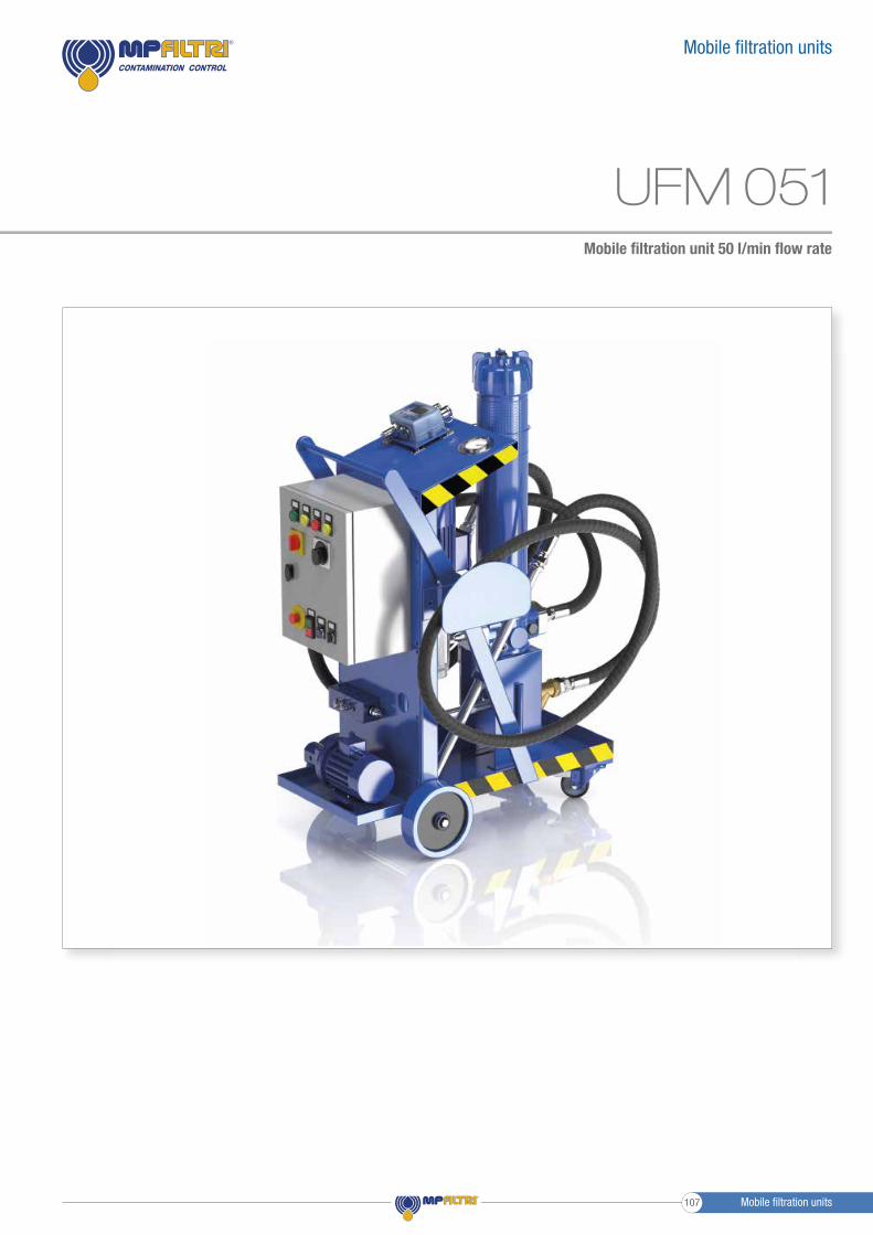
Mobile fi ltration unit 50 l/min fl ow rate
UFM 051
Mobile fi ltration units107
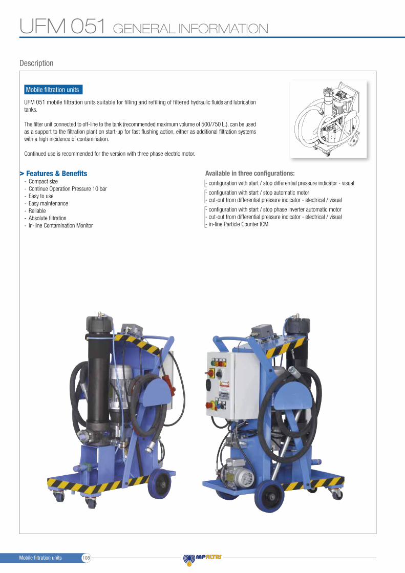
UFM 051 GENERAL INFORMATION
Mobile fi ltration units
UFM 051 mobile filtration units suitable for filling and refilling of filtered hydraulic fl uids and lubrication tanks.
The fi lter unit connected to off-line to the tank (recommended maximum volume of 500/750 L.), can be used as a support to the fi ltration plant on start-up for fast fl ushing action, either as additional fi ltration systems with a high incidence of contamination.
Continued use is recommended for the version with three phase electric motor.
Description
Features & Benefi ts- Compact size- Continue Operation Pressure 10 bar- Easy to use- Easy maintenance- Reliable- Absolute fi ltration- In-line Contamination Monitor
Available in three confi gurations:- confi guration with start / stop differential pressure indicator - visual
- confi guration with start / stop automatic motor - cut-out from differential pressure indicator - electrical / visual
- confi guration with start / stop phase inverter automatic motor - cut-out from differential pressure indicator - electrical / visual- in-line Particle Counter ICM
>
Mobile fi ltration units 108
UFM 051GENERAL INFORMATION
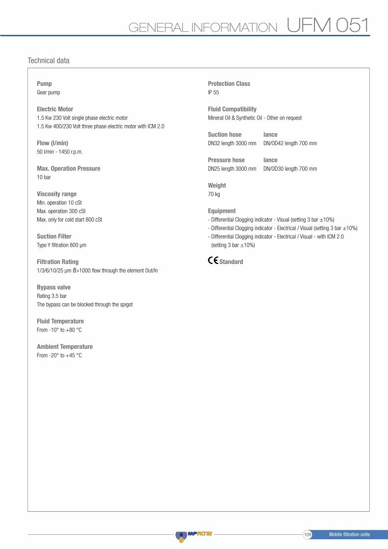
Technical data
PumpGear pump
Electric Motor1.5 Kw 230 Volt single phase electric motor
1.5 Kw 400/230 Volt three phase electric motor with ICM 2.0
Flow (l/min)50 l/min - 1450 r.p.m.
Max. Operation Pressure10 bar
Viscosity rangeMin. operation 10 cSt
Max. operation 300 cSt
Max. only for cold start 800 cSt
Suction FilterType Y filtration 800 μm
Filtration Rating1/3/6/10/25 μm ß>1000 flow through the element Out/In
Bypass valveRating 3.5 bar
The bypass can be blocked through the spigot
Fluid TemperatureFrom -10° to +80 °C
Ambient TemperatureFrom -20° to +45 °C
Protection ClassIP 55
Fluid CompatibilityMineral Oil & Synthetic Oil - Other on request
Suction hose lanceDN32 length 3000 mm DN/OD42 length 700 mm
Pressure hose lanceDN25 length 3000 mm DN/OD30 length 700 mm
Weight70 kg
Equipment- Differential Clogging indicator - Visual (setting 3 bar ±10%)
- Differential Clogging indicator - Electrical / Visual (setting 3 bar ±10%)
- Differential Clogging indicator - Electrical / Visual - with ICM 2.0
(setting 3 bar ±10%)
Standard
Mobile filtration units109
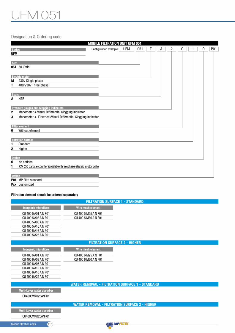
SeriesUFM
Size
Electric motor
Seals
051
M
A
T
50 l/min
230V Single phase
NBR
400/230V Three phase
Pressure gauges and Clogging indicators
Filtration surface
2
1
3
2
Filter element0 Without element
Manometer + Visual Differential Clogging indicator
Standard
OptionO1
No optionsICM 2.0 particle counter (available three phase electric motor only)
Manometer + Electrical/Visual Differential Clogging indicator
Higher
Configuration example: UFM A 2 P011051 T O O
CU 400 6 A01 A N P01CU 400 6 A03 A N P01CU 400 6 A06 A N P01CU 400 6 A10 A N P01CU 400 6 A16 A N P01CU 400 6 A25 A N P01
CU 400 6 M25 A N P01CU 400 6 M60 A N P01
Inorganic microfibre Wire mesh element
FILTRATION SURFACE 2 - HIGHER
OptionP01Pxx
MP Filtri standardCustomized
MOBILE FILTRATION UNIT UFM 051
Designation & Ordering code
CU 400 5 A01 A N P01CU 400 5 A03 A N P01CU 400 5 A06 A N P01CU 400 5 A10 A N P01CU 400 5 A16 A N P01CU 400 5 A25 A N P01
CU 400 5 M25 A N P01CU 400 5 M60 A N P01
Inorganic microfibre Wire mesh element
Filtration element should be ordered separately
FILTRATION SURFACE 1 - STANDARD
Multi-Layer water absorber
WATER REMOVAL - FILTRATION SURFACE 1 - STANDARD
CU4005WA025ANP01
Multi-Layer water absorber
WATER REMOVAL - FILTRATION SURFACE 2 - HIGHER
CU4006WA025ANP01
UFM 051
Mobile filtration units 110
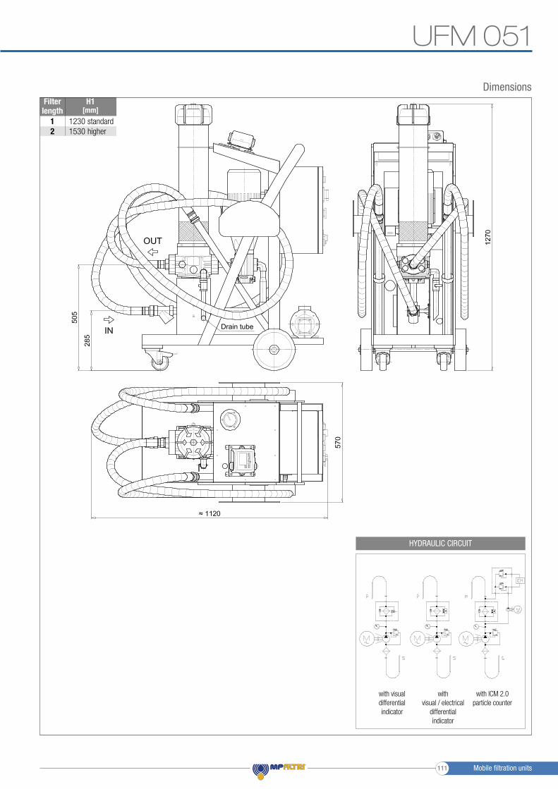
Filter length
H1[mm]
12
standardhigher
12301530
Dimensions
UFM 051
with visual differential indicator
with visual / electrical
differential indicator
with ICM 2.0particle counter
HYDRAULIC CIRCUIT
Drain tube
Mobile filtration units111

Mobile filtration units 112
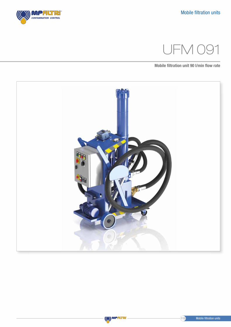
Mobile fi ltration unit 90 l/min fl ow rate
Mobile fi ltration units
UFM 091
Mobile fi ltration units113
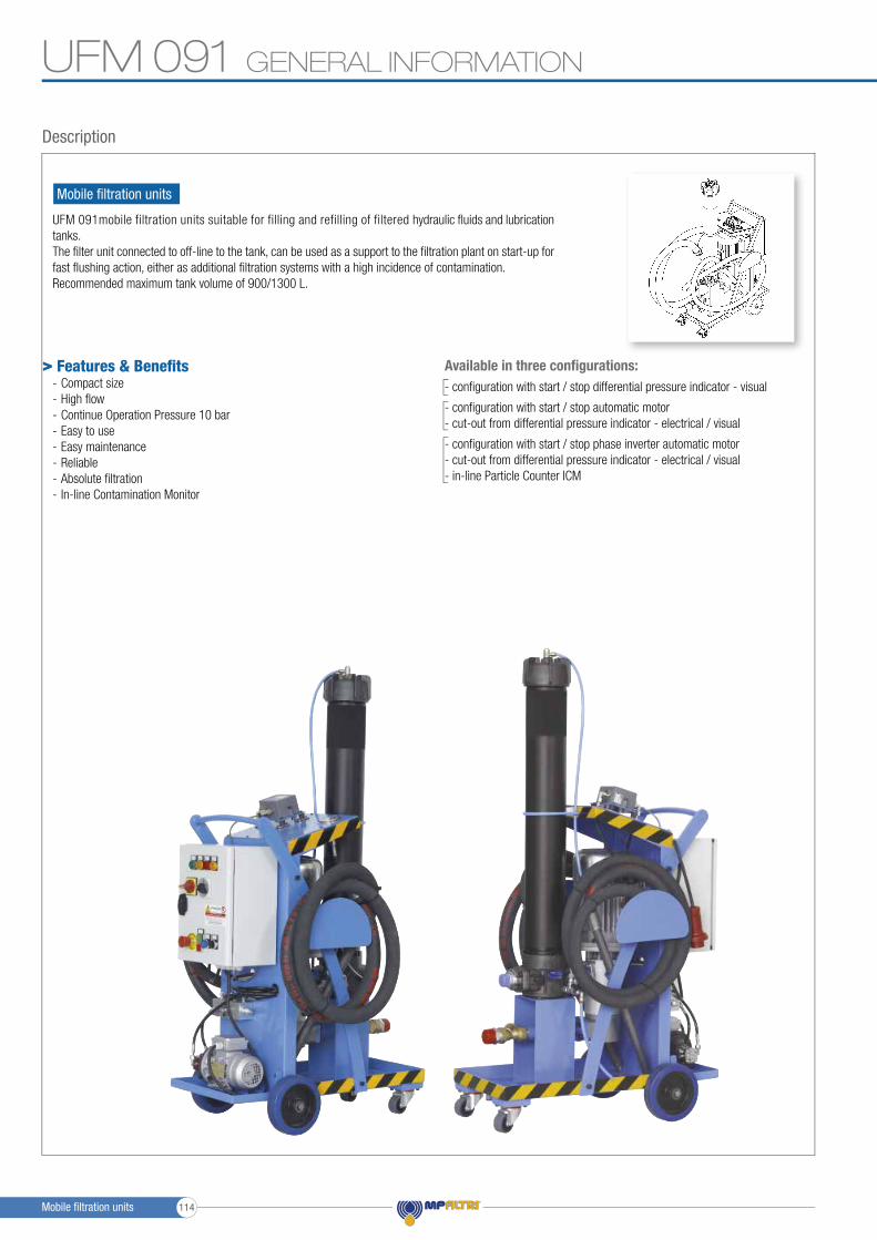
UFM 091
Mobile fi ltration units
UFM 091mobile filtration units suitable for filling and refilling of filtered hydraulic fl uids and lubrication tanks.The fi lter unit connected to off-line to the tank, can be used as a support to the fi ltration plant on start-up for fast fl ushing action, either as additional fi ltration systems with a high incidence of contamination.Recommended maximum tank volume of 900/1300 L.
GENERAL INFORMATION
Description
> Features & Benefi ts- Compact size- High fl ow- Continue Operation Pressure 10 bar- Easy to use- Easy maintenance- Reliable- Absolute fi ltration- In-line Contamination Monitor
Available in three confi gurations:- confi guration with start / stop differential pressure indicator - visual
- confi guration with start / stop automatic motor - cut-out from differential pressure indicator - electrical / visual
- confi guration with start / stop phase inverter automatic motor - cut-out from differential pressure indicator - electrical / visual- in-line Particle Counter ICM
Mobile fi ltration units 114

UFM 091GENERAL INFORMATION
Technical data
PumpScrew pump
Electric Motor2.2 kW 400/230 V three phase 4-pole
Flow (l/min)90 l/min - 1450 r.p.m.
Max. Operation Pressure10 bar
Viscosity rangeMin. operation 10 cSt
Max. operation 800 cSt
Max. only for cold start 2000 cSt
Suction FilterType Y filtration 800 μm
Filtration Rating1/3/6/10/25 μm ß>1000 flow through the element Out/In
Bypass valveRating 3.5 bar with bypass.
The bypass can be blocked through the spigot
Fluid TemperatureFrom -10° to +80 °C
Ambient TemperatureFrom -20° to +45 °C
Protection ClassIP 55
SealNBR
Fluid CompatibilityMineral Oil & Synthetic Oil - Water Glycol
Suction hose lanceDN50 length 3000 mm DN/OD50 length 700 mm
Pressure hose lanceDN38 length 3000 mm DN/OD42 length 700 mm
Weight105 kg
Equipment- Differential Clogging indicator - Visual (setting 3 bar ±10%)
- Differential Clogging indicator - Electrical / Visual (setting 3 bar ±10%)
- Differential Clogging indicator - Electrical / Visual - with ICM 2.0
(setting 3 bar ±10%)
Standard
Mobile filtration units115
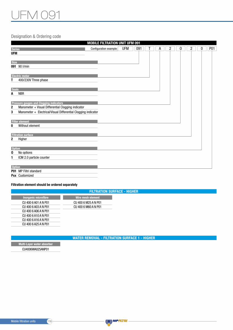
SeriesUFM
Size
Electric motor
Seals
091
T
A
90 l/min
400/230V Three phase
NBR
Pressure gauges and Clogging indicators23
Filter element0 Without element
Filtration surface2 Higher
Manometer + Visual Differential Clogging indicator
OptionO1
No optionsICM 2.0 particle counter
Manometer + Electrical/Visual Differential Clogging indicator
Configuration example: UFM A 2 P012091 T O 0
CU 400 6 A01 A N P01CU 400 6 A03 A N P01CU 400 6 A06 A N P01CU 400 6 A10 A N P01CU 400 6 A16 A N P01CU 400 6 A25 A N P01
CU 400 6 M25 A N P01CU 400 6 M60 A N P01
Wire mesh element
OptionP01Pxx
MP Filtri standardCustomized
MOBILE FILTRATION UNIT UFM 091
Filtration element should be ordered separately
Designation & Ordering code
FILTRATION SURFACE - HIGHER
Inorganic microfibre
Multi-Layer water absorber
WATER REMOVAL - FILTRATION SURFACE 1 - HIGHER
CU4006WA025ANP01
UFM 091
Mobile filtration units 116
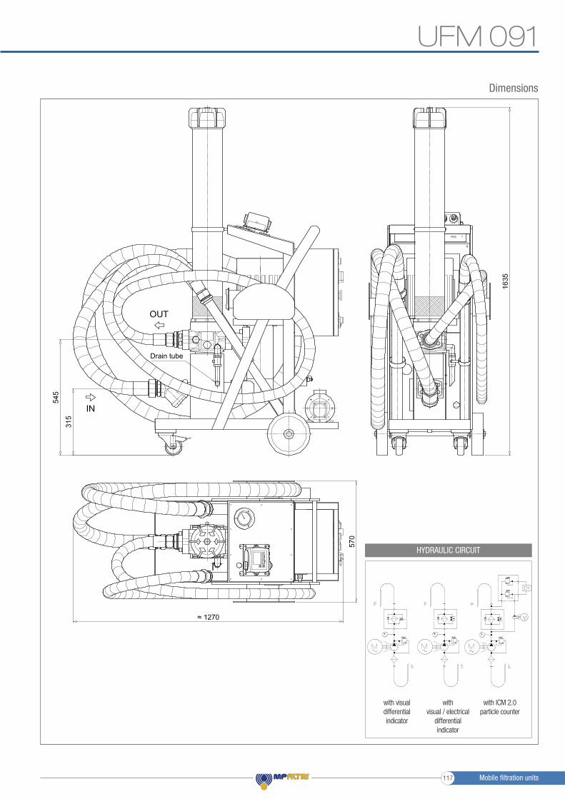
with visual differential indicator
with visual / electrical
differential indicator
with ICM 2.0particle counter
HYDRAULIC CIRCUIT
Dimensions
UFM 091
Drain tube
Mobile filtration units117

Mobile filtration units 118

Mobile fi ltration unit 180 l/min fl ow rate
Mobile fi ltration units
UFM 181
Mobile fi ltration units119

UFM 181
UFM 181 mobile filtration units suitable for filling and refilling of filtered hydraulic fl uids and lubrication tanks.The fi lter unit connected to off-line to the tank, can be used as a support to the fi ltration plant on start-up for fast fl ushing action, either as additional fi ltration systems with a high incidence of contamination.Recommended maximum tank volume of 1800/2700 L.
GENERAL INFORMATION
Mobile fi ltration units
Description
> Features & Benefi ts- Compact size- High fl ow- Continue Operation Pressure 10 bar- Easy to use- Easy maintenance- Reliable- Absolute fi ltration- In-line Contamination Monitor
Available in two confi gurations:- confi guration with start / stop automatic motor - cut-out from differential pressure indicator - electrical / visual
- confi guration with start / stop phase inverter automatic motor - cut-out from differential pressure indicator - electrical / visual- in-line Particle Counter ICM
Mobile fi ltration units 120
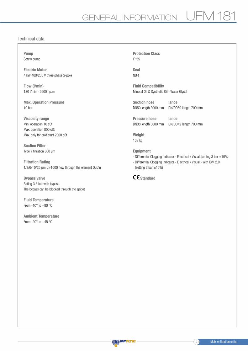
UFM 181GENERAL INFORMATION
Technical data
PumpScrew pump
Electric Motor4 kW 400/230 V three phase 2-pole
Flow (l/min)180 l/min - 2900 r.p.m.
Max. Operation Pressure10 bar
Viscosity rangeMin. operation 10 cSt
Max. operation 800 cSt
Max. only for cold start 2000 cSt
Suction FilterType Y filtration 800 μm
Filtration Rating1/3/6/10/25 μm ß>1000 flow through the element Out/In
Bypass valveRating 3.5 bar with bypass.
The bypass can be blocked through the spigot
Fluid TemperatureFrom -10° to +80 °C
Ambient TemperatureFrom -20° to +45 °C
Protection ClassIP 55
SealNBR
Fluid CompatibilityMineral Oil & Synthetic Oil - Water Glycol
Suction hose lanceDN50 length 3000 mm DN/OD50 length 700 mm
Pressure hose lanceDN38 length 3000 mm DN/OD42 length 700 mm
Weight109 kg
Equipment- Differential Clogging indicator - Electrical / Visual (setting 3 bar ±10%)
- Differential Clogging indicator - Electrical / Visual - with ICM 2.0
(setting 3 bar ±10%)
Standard
Mobile filtration units121
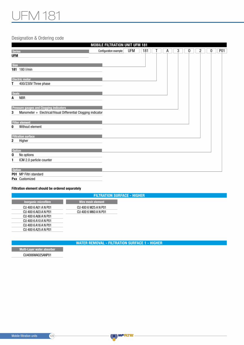
SeriesUFM
Size
Electric motor
Seals
181
T
A
180 l/min
400/230V Three phase
NBR
Pressure gauges and Clogging indicators3
Filter element0 Without element
Filtration surface2 Higher
OptionO1
No optionsICM 2.0 particle counter
Manometer + Electrical/Visual Differential Clogging indicator
Configuration example: UFM A 3 P012181 T O 0
CU 400 6 A01 A N P01CU 400 6 A03 A N P01CU 400 6 A06 A N P01CU 400 6 A10 A N P01CU 400 6 A16 A N P01CU 400 6 A25 A N P01
CU 400 6 M25 A N P01CU 400 6 M60 A N P01
Wire mesh element
OptionP01Pxx
MP Filtri standardCustomized
MOBILE FILTRATION UNIT UFM 181
Filtration element should be ordered separately
Designation & Ordering code
FILTRATION SURFACE - HIGHER
Inorganic microfibre
Multi-Layer water absorber
WATER REMOVAL - FILTRATION SURFACE 1 - HIGHER
CU4006WA025ANP01
UFM 181
Mobile filtration units 122
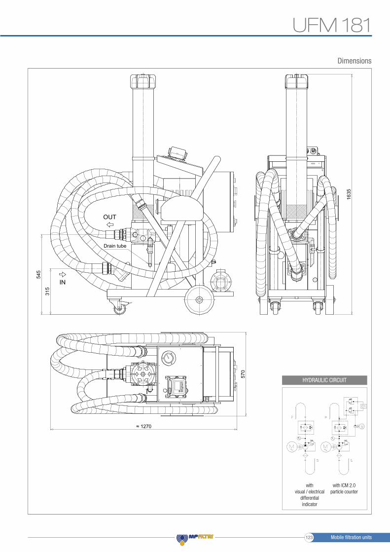
with visual / electrical
differential indicator
with ICM 2.0particle counter
HYDRAULIC CIRCUIT
Dimensions
UFM 181
Drain tube
Mobile filtration units123

Mobile filtration units 124

Mobile fi ltration unit 90/180 l/min fl ow rate
Mobile fi ltration units
UFM 919
Mobile fi ltration units125

UFM 919 GENERAL INFORMATION
UFM 919 mobile filtration units suitable for filling and refilling of filtered hydraulic fl uids and lubrication tanks.The fi lter unit connected to off-line to the tank, can be used as a support to the fi ltration plant on start-up for fast fl ushing action, either as additional fi ltration systems with a high incidence of contamination.Two-speed electric motor with programmable fl ow of 90 or 180 l/min.
Mobile fi ltration units
Description
Features & Benefi ts- Compact size- High fl ow- Continue Operation Pressure 10 bar- Easy to use- Easy maintenance- Reliable- Absolute fi ltration- In-line Contamination Monitor
Possible applications- Flow rate 90 l/min for filling or topping up tanks with a volume of less than 1000 liters- Flow rate 90 l/min for depollution of tanks with a volume of less than 1000 liters- Flow rate 90 l / min for the treatment of high viscosity oils- Flow rate 90 l / min for a cold start phase then fl ow rate 180 l/min after temperature rise.
- Flow rate 180 l/min for fi lling or topping up tanks with a volume greater than 2000 liters- Flow rate 180 l/min for the depollution of tanks with a volume of less than 2000 liters
Available in two confi gurations:- confi guration with start / stop automatic motor - cut-out from differential pressure indicator - electrical / visual
- confi guration with start / stop phase inverter automatic motor - cut-out from differential pressure indicator - electrical / visual- in-line Particle Counter ICM 2.0
>
Mobile fi ltration units 126

UFM 919
Technical data
PumpScrew pump
Electric Motor3.7/5 kW 400/230 V three phase 2/4-pole
Flow (l/min)90 l/min - 1450 r.p.m. / 180 l/min - 2900 r.p.m.
Max. Operation Pressure10 bar
Viscosity rangeMin. operation 10 cSt
Max. operation 800 cSt
Max. only for cold start 2000 cSt
Suction FilterType Y filtration 800 μm
Filtration Rating1/3/6/10/25 μm ß>1000 flow through the element Out/In
Bypass valveRating 3.5 bar with bypass.
The bypass can be blocked through the spigot
Fluid TemperatureFrom -10° to +80 °C
Ambient TemperatureFrom -20° to +45 °C
Protection ClassIP 55
SealNBR
Fluid CompatibilityMineral Oil & Synthetic Oil - Water Glycol
Suction hose lance lance 90°DN50 length 3000 mm DN/OD50 length 700 mm
Pressure hose lanceDN38 length 3000 mm DN/OD42 length 700 mm
Weight120 kg
Equipment- Differential Clogging indicator - Electrical / Visual (setting 3 bar ±10%)
- Differential Clogging indicator - Electrical / Visual - with ICM 2.0
(setting 3 bar ±10%)
Standard
GENERAL INFORMATION
DN/OD40 length 700 mm
Mobile filtration units127

SeriesUFM
Size
Electric motor
Seals
919
T
A
90-180 l/min
400/230V Three phase - 2/4 pole
NBR
Pressure gauges and Clogging indicators3
Filter element0 Without element
Filtration surface2 Higher
OptionO1
No optionsICM 2.0 particle counter
Manometer + Electrical/Visual Differential Clogging indicator
Configuration example: UFM A 3 P012919 T O 0
CU 400 6 A01 A N P01CU 400 6 A03 A N P01CU 400 6 A06 A N P01CU 400 6 A10 A N P01CU 400 6 A16 A N P01CU 400 6 A25 A N P01
CU 400 6 M25 A N P01CU 400 6 M60 A N P01
Wire mesh element
OptionP01Pxx
MP Filtri standardCustomized
MOBILE FILTRATION UNIT UFM 919
Filtration element should be ordered separately
Designation & Ordering code
FILTRATION SURFACE - HIGHER
Inorganic microfibre
Multi-Layer water absorber
WATER REMOVAL - FILTRATION SURFACE 1 - HIGHER
CU4006WA025ANP01
UFM 919
Mobile filtration units 128

with visual / electrical
differential indicator
with ICM 2.0particle counter
HYDRAULIC CIRCUIT
Dimensions
UFM 919
Drain tube
Mobile filtration units129

Mobile filtration units 130
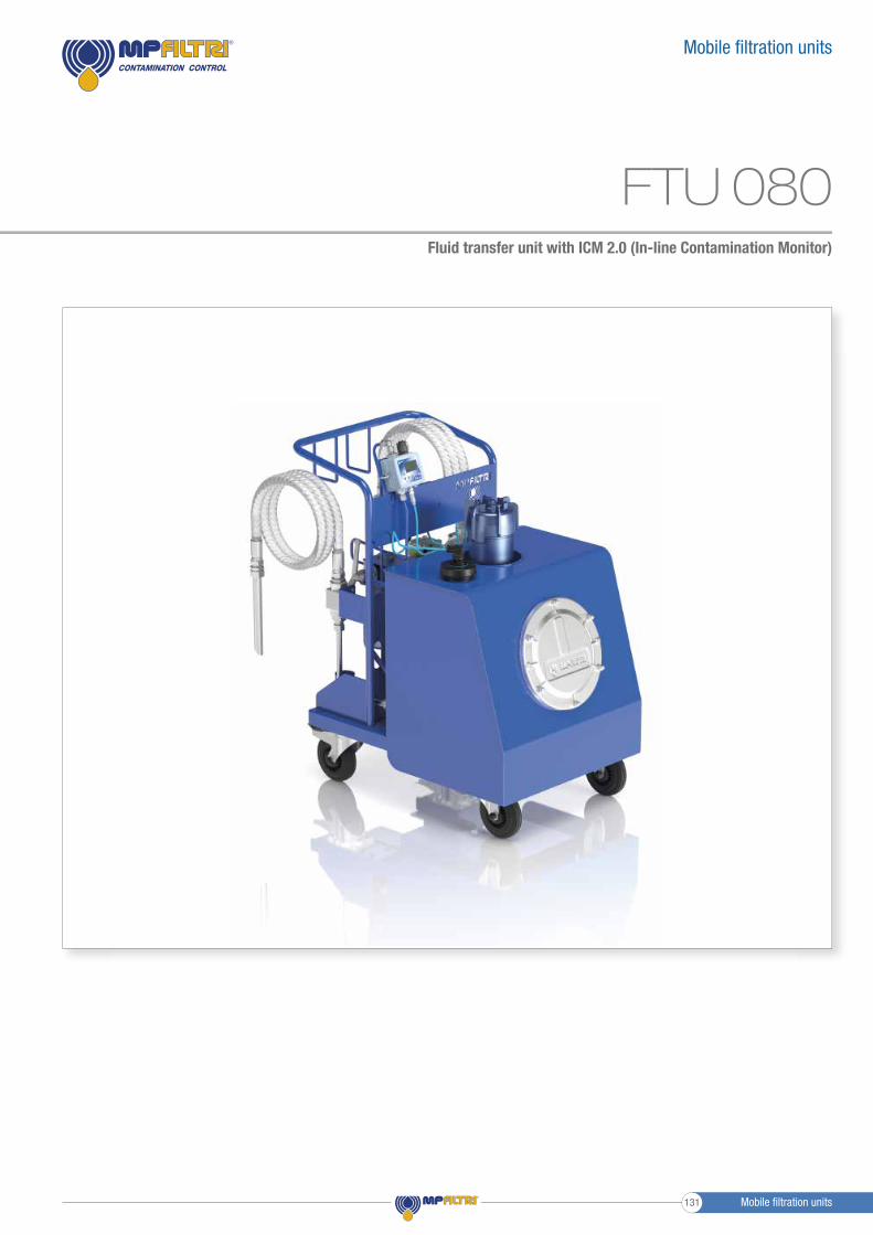
Fluid transfer unit with ICM 2.0 (In-line Contamination Monitor)
Mobile fi ltration units
FTU 080
Mobile fi ltration units131

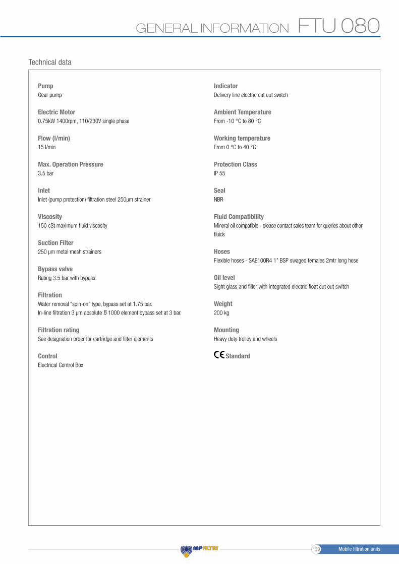
FTU 080 GENERAL INFORMATION
Fluid Transfer Unit
FTU 080 Fluid Transfer unit suitable for filling, recirculation - via onboard 80L reservoir - and emptying of filtered hydraulic fluids and lubrication tanks.
The FTU can be utilised either as additional filtration to a system with a high incidence of contamination, or can be used as a standalone recirculating filtration circuit to clean fluid to a predetermined contamination level - monitored by the onboard ICM - prior to transfer of fluid to the system.
Description
Features & Benefits- Compact size- Easy to use- Easy maintenance- Reliable- Absolute filtration- In-line Contamination Monitor
Possible applications- Low flow rate for filling of reservoirs- Low-flow filtration for off-line tanks- Pre filtration ability of fluid prior to filling of hydraulic system
>
Mobile filtration units 132
FTU 080GENERAL INFORMATION
Technical data
PumpGear pump
Electric Motor0.75kW 1400rpm, 110/230V single phase
Flow (l/min)15 l/min
Max. Operation Pressure3.5 bar
InletInlet (pump protection) filtration steel 250μm strainer
Viscosity150 cSt maximum fluid viscosity
Suction Filter250 µm metal mesh strainers
Bypass valveRating 3.5 bar with bypass
FiltrationWater removal “spin-on” type, bypass set at 1.75 bar.
In-line filtration 3 μm absolute ß 1000 element bypass set at 3 bar.
Filtration ratingSee designation order for cartridge and filter elements
ControlElectrical Control Box
IndicatorDelivery line electric cut out switch
Ambient TemperatureFrom -10 °C to 80 °C
Working temperatureFrom 0 °C to 40 °C
Protection ClassIP 55
SealNBR
Fluid CompatibilityMineral oil compatible - please contact sales team for queries about other
fluids
HosesFlexible hoses - SAE100R4 1” BSP swaged females 2mtr long hose
Oil levelSight glass and filler with integrated electric float cut out switch
Weight200 kg
MountingHeavy duty trolley and wheels
Standard
Mobile filtration units133
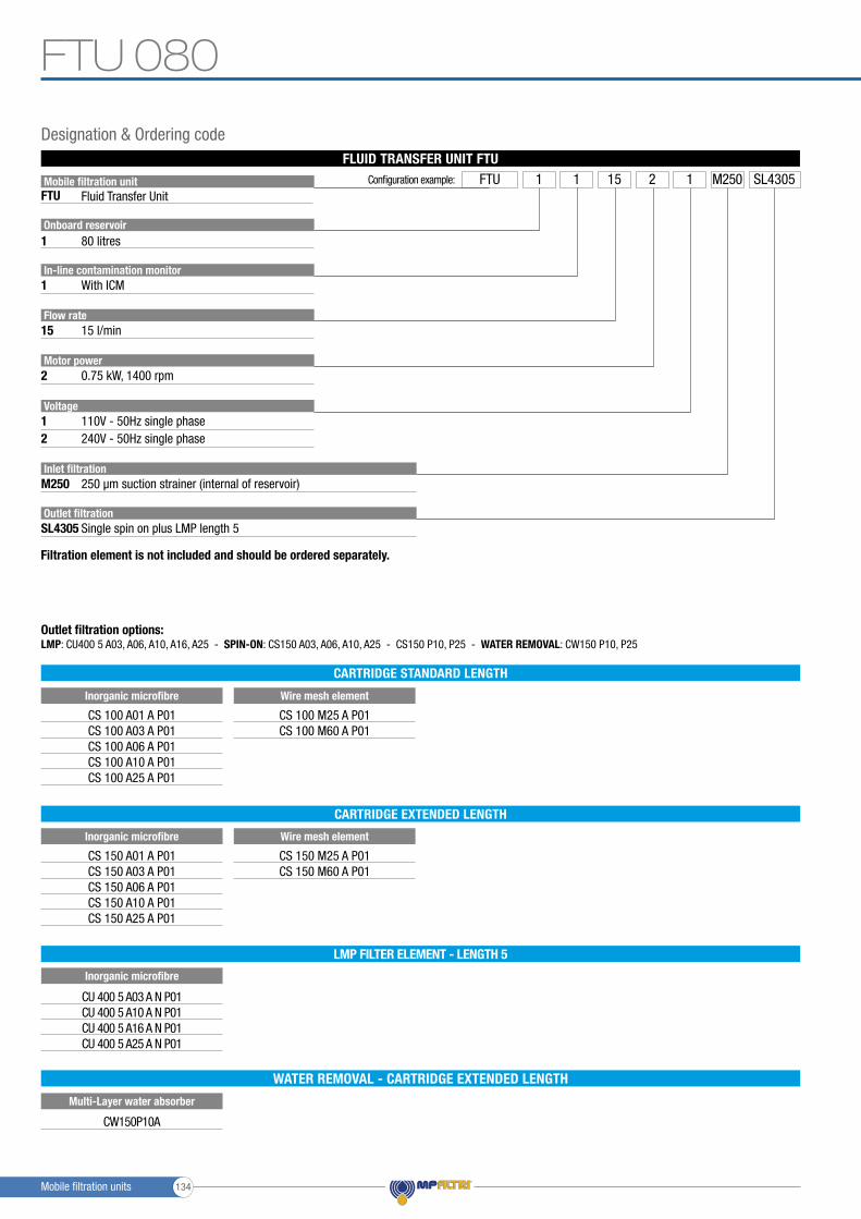
Mobile filtration unitFTU
Onboard reservoir
Motor power
Inlet filtration
Outlet filtration
In-line contamination monitor
Flow rate
1
2
M250
SL4305
1
15
80 litres
Fluid Transfer Unit
0.75 kW, 1400 rpm
Voltage12
110V - 50Hz single phase240V - 50Hz single phase
250 μm suction strainer (internal of reservoir)
Single spin on plus LMP length 5
With ICM
15 l/min
Configuration example: FTU 1 SL4305151 M2502 1
LMP: CU400 5 A03, A06, A10, A16, A25 - SPIN-ON: CS150 A03, A06, A10, A25 - CS150 P10, P25 - WATER REMOVAL: CW150 P10, P25Outlet filtration options:
Filtration element is not included and should be ordered separately.
CS 100 A01 A P01CS 100 A03 A P01CS 100 A06 A P01CS 100 A10 A P01CS 100 A25 A P01
Inorganic microfibre
CS 150 A01 A P01CS 150 A03 A P01CS 150 A06 A P01CS 150 A10 A P01CS 150 A25 A P01
Inorganic microfibre
CU 400 5 A03 A N P01CU 400 5 A10 A N P01CU 400 5 A16 A N P01CU 400 5 A25 A N P01
Inorganic microfibre
CS 100 M25 A P01CS 100 M60 A P01
Wire mesh element
CS 150 M25 A P01CS 150 M60 A P01
Wire mesh element
FLUID TRANSFER UNIT FTU
Designation & Ordering code
CARTRIDGE STANDARD LENGTH
CARTRIDGE EXTENDED LENGTH
LMP FILTER ELEMENT - LENGTH 5
Multi-Layer water absorber
WATER REMOVAL - CARTRIDGE EXTENDED LENGTH
CW150P10A
FTU 080
Mobile filtration units 134
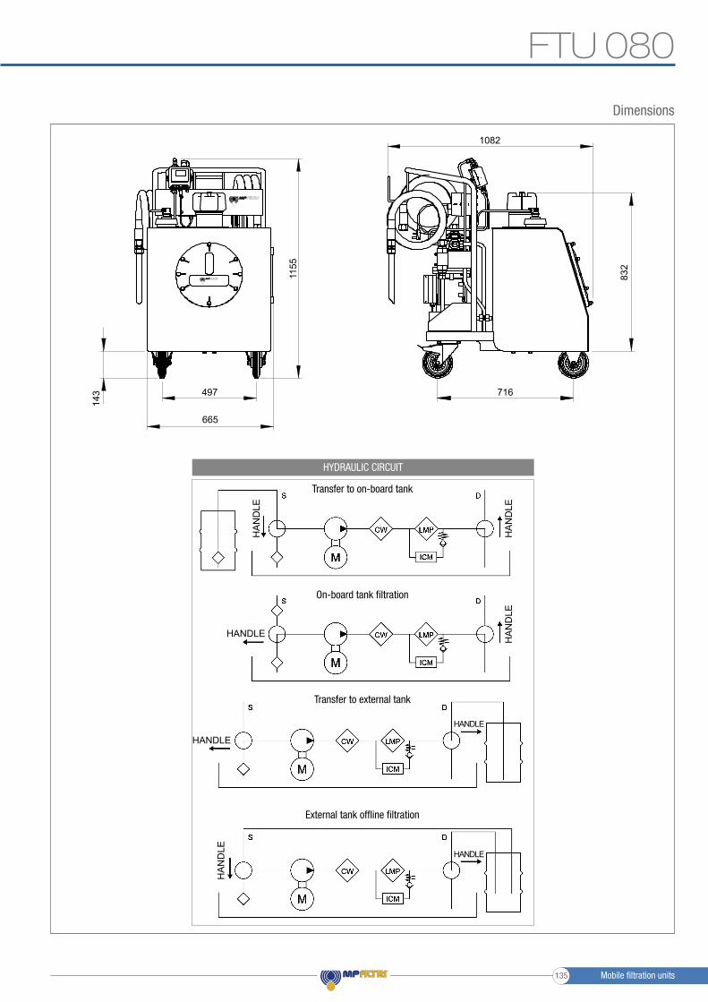
1082
716497
832
1155
143
665
Dimensions
FTU 080
HYDRAULIC CIRCUIT
HA
ND
LE
HA
ND
LE
HA
ND
LE
HANDLE
HANDLE
HANDLE
HA
ND
LE HANDLE
Transfer to on-board tank
On-board tank filtration
Transfer to external tank
External tank offline filtration
Mobile filtration units135
mpfiltri.com
WORLDWIDE
TO PERFORM
NETWORK
PASSION
CM
PE
N00
1M
EN
- R
ev. 1
2-20
20
HEADQUARTERS
ITALFILTRI LLCMoscow - Russia+7 (495) 220 94 [email protected]
MP Filtri Canada Inc.Concord - Ontario - Canada+1 905 303 [email protected]
MP Filtri France SASVilleneuve la GarenneFrance+33 (0)1 40 86 47 [email protected]
MP Filtri Germany GmbHSt. Ingbert - Germany+49 (0) 6894 [email protected]
MP Filtri India Pvt. Ltd.Bangalore - India+91 80 4147 7444 / +91 80 4146 [email protected]
MP Filtri (Shanghai) Co., Ltd.Shanghai - Minhang District - China+86 21 58919916 [email protected]
MP Filtri U.K. Ltd.Bourton on the WaterGloucestershire - United Kingdom+44 (0) 1451 822 [email protected]
MP Filtri U.S.A. Inc.Quakertown, PA - U.S.A.+1 215 529 [email protected]
BRANCH OFFICES
MP Filtri S.p.A.Pessano con BornagoMilano - Italy+39 02 [email protected]