Embed Size (px)
Citation preview
IPS-C-PI-240(2)
CONSTRUCTION STANDARD
FOR
PLANT PIPING SYSTEM
SECOND REVISION
NOVEMBER 2008
This standard specification is reviewed and updated by the relevant technical committee on July 2015 . The approved modifications are included in the present issue of IPS.
ستاندارد اجرايي ا
براي
سيستم لوله كشي داخل كارخانه
ويرايش دوم
1387آبان
ماه سال مرداداين استاندارد توسط كميته فني مربوطه در
اصالحات تاييد شده در نسخه حاضر . بازنگري شده است 1394
IPS ستا گرديدهاعمال.
This Standard is the property of Iranian Ministry of
Petroleum. All rights are reserved to the owner. Neither
whole nor any part of this document maybe disclosed to any
third party, reproduced, stored in any retrieval system or
transmitted in any form or by any means without the prior
written consent of the Iranian Ministry of Petroleum.
تمام حقوق آن متعلق به . اين استاندارد متعلق به وزارت نفت ايران است
مالك آن بوده و نبايد بدون رضايت كتبي وزارت نفت ايران، تمام يا بخشي از
اين استاندارد، به هر شكل يا وسيله ازجمله تكثير، ذخيره سازي، انتقال، يا
.روش ديگري در اختيار افراد ثالث قرار گيرد
FOREWORD
The Iranian Petroleum Standards (IPS) reflect the
views of the Iranian Ministry of Petroleum and are
intended for use in the oil and gas production
facilities, oil refineries, chemical and
petrochemical plants, gas handling and processing
installations and other such facilities.
IPS is based on internationally acceptable
standards and includes selections from the items
stipulated in the referenced standards. They are
also supplemented by additional requirements
and/or modifications based on the experience
acquired by the Iranian Petroleum Industry and the
local market availability. The options which are
not specified in the text of the standards are
itemized in data sheet/s, so that, the user can select
his appropriate preferences therein.
The IPS standards are therefore expected to be
sufficiently flexible so that the users can adapt
these standards to their requirements. However,
they may not cover every requirement of each
project. For such cases, an addendum to IPS
Standard shall be prepared by the user which
elaborates the particular requirements of the user.
This addendum together with the relevant IPS shall
form the job specification for the specific project
or work.
The IPS is reviewed and up-dated approximately
every five years. Each standards are subject to
amendment or withdrawal, if required, thus the
latest edition of IPS shall be applicable
The users of IPS are therefore requested to send
their views and comments, including any
addendum prepared for particular cases to the
following address. These comments and
recommendations will be reviewed by the relevant
technical committee and in case of approval will
be incorporated in the next revision of the
standard.
Standards and Research department
No.19, Street14, North kheradmand
Karimkhan Avenue, Tehran, Iran .
Postal Code- 1585886851
Tel: 88810459-60 & 66153055
Fax: 88810462
Email: [email protected]
پيش گفتار
منعكس كننده )IPS(استانداردهاي صنايع نفت ايران
ديدگاههاي وزارت نفت ايران است و براي استفاده در
تأسيسات توليد نفت و گاز، پااليشگاههاي نفت، واحدهاي
شيميائي و پتروشيمي، تأسيسات انتقال و فراورش گاز و ساير
.تأسيسات مشابه تهيه شده است
براساس استانداردهاي قابل قبول بين استانداردهاي نفت،
هائي از استانداردهاي مرجع المللي تهيه شده و شامل گزيده
همچنين براساس تجربيات صنعت نفت كشور و . باشد مي
قابليت تأمين كاال از بازار داخلي و نيز برحسب نياز، مواردي
. بطور تكميلي و يا اصالحي در اين استاندارد لحاظ شده است
هاي فني كه در متن استانداردها آورده نشده از گزينه مواردي
ها بصورت شماره گذاري شده براي استفاده است در داده برگ
.مناسب كاربران آورده شده است
استانداردهاي نفت، بشكلي كامالً انعطاف پذير تدوين شده
. است تا كاربران بتوانند نيازهاي خود را با آنها منطبق نمايند
هاي پروژه ها را پوشش ل ممكن است تمام نيازمنديبا اين حا
اي كه نيازهاي خاص آنها در اين گونه موارد بايد الحاقيه. ندهند
اين الحاقيه همراه با . نمايد تهيه و پيوست نمايند را تامين مي
استاندارد مربوطه، مشخصات فني آن پروژه و يا كار خاص را
.تشكيل خواهند داد
تقريباً هر پنج سال يكبار مورد بررسي قرار استانداردهاي نفت
ها ممكن است در اين بررسي. گردند گرفته و روزآمد مي
اي به آن اضافه شود و بنابراين استانداردي حذف و يا الحاقيه
.همواره آخرين ويرايش آنها مالك عمل مي باشد
نظرها و شود نقطه از كاربران استاندارد، درخواست مي
اي كه براي موارد حي و يا هرگونه الحاقيهپيشنهادات اصال
نظرات و . اند، به نشاني زير ارسال نمايند خاص تهيه نموده
هاي فني مربوطه بررسي و در پيشنهادات دريافتي در كميته
صورت تصويب در تجديد نظرهاي بعدي استاندارد منعكس
.خواهد شد
كوچه ايران، تهران، خيابان كريمخان زند، خردمند شمالي،
19چهاردهم، شماره
اداره تحقيقات و استانداردها
1585886851: كدپستي
66153055و 88810459 - 60: تلفن
021-88810462: دور نگار
[email protected]: پست الكترونيكي
GENERAL DEFINITIONS:
Throughout this Standard the following definitions
shall apply.
:تعاريف عمومي
. در اين استاندارد تعاريف زير به كار مي رود
COMPANY :
Refers to one of the related and/or affiliated
companies of the Iranian Ministry of Petroleum
such as National Iranian Oil Company, National
Iranian Gas Company, National Petrochemical
Company and National Iranian Oil Refinery And
Distribution Company.
: شركت
به يكي از شركت هاي اصلي و يا وابسته به وزارت نفت، مثل
شركت ملي نفت ايران، شركت ملي گاز ايران، شركت ملي
هاي صنايع پتروشيمي و شركت ملي پااليش و پخش فرآورده
.شود نفتي اطالق مي
PURCHASER :
Means the “Company" where this standard is a part
of direct purchaser order by the “Company”, and
the “Contractor” where this Standard is a part of
contract document.
:خريدار
خريد يعني شركتي كه اين استاندارد بخشي از مدارك سفارش
باشد و يا پيمانكاري كه اين استاندارد مستقيم آن شركت مي
. بخشي از مدارك قرارداد آن است
VENDOR AND SUPPLIER:
Refers to firm or person who will supply and/or
fabricate the equipment or material.
:فروشنده و تامين كننده
ه تجهيزات و كاالهاي شود ك به موسسه و يا شخصي گفته مي
.نمايد مورد لزوم صنعت را تامين مي
CONTRACTOR:
Refers to the persons, firm or company whose
tender has been accepted by the company.
:پيمانكار
شود كه پيشنهادش به شخص، موسسه و يا شركتي گفته مي
.براي مناقصه پذيرفته شده است
EXECUTOR :
Executor is the party which carries out all or part of
construction and/or commissioning for the project.
:مجري
شود كه تمام يا قسمتي از كارهاي مجري به گروهي اطالق مي
.اجرائي و يا راه اندازي پروژه را انجام دهد
INSPECTOR :
The Inspector referred to in this Standard is a
person/persons or a body appointed in writing by
the company for the inspection of fabrication and
installation work.
:بازرس
اي اطالق گروه يا موسسه/در اين استاندارد بازرس به فرد
شود كه كتباً توسط كارفرما براي بازرسي، ساخت و نصب مي
.رفي شده باشدتجهيزات مع
SHALL:
Is used where a provision is mandatory.
SHOULD:
Is used where a provision is advisory only.
:بايد
.شود براي كاري كه انجام آن اجباري است، استفاده مي
:توصيه
.رود شود، بكار مي براي كاري كه ضرورت انجام آن توصيه مي
WILL:
Is normally used in connection with the action by
the “Company” rather than by a contractor,
supplier or vendor.
: ترجيح
شود كه انجام آن كار براساس معموالً در جايي استفاده مي
.نظارت شركت باشد
MAY:
Is used where a provision is completely
discretionary.
: ممكن است
.رود باشد، بكار مي كاري كه انجام آن اختياري مي براي
Nov. 2008/ 1387آبان
IPS-C-PI-240(2)
1
CONTENTS : Page
No
:مطالب فهرست
1. SCOPE ................................................................ 4
4 ..................................................... كاربرد دامنه - 1
2. REFERENCES .................................................. 5
5 ............................................................. مراجع -2
3. DEFINITIONS AND TERMINOLOGY ......... 6
6 ................................................ و واژگان فيتعار - 3
3.1 Engineer ....................................................... 6
6 ............................................ كارفرما ندهينما 1- 3
4. ABBREVIATIONS............................................ 6
6 ......................................................... اختصارها - 4
4.1"BOM" denotes "Bill of Material" ............. 6
4 -1 »BOM «6 .................................. اجناس ستيل
5. UNITS ................................................................. 6
6 ............................................................ واحدها -5
6. GENERAL REQUIREMENTS ....................... 7
7 .................................................. يالزامات عموم - 6
6.1 Documentations ........................................... 7
7 ................................................. ارائه مدارك 1- 6
6.2 Storing .......................................................... 8
8 ....................................................... انبارش 2- 6
7. FABRICATION ................................................. 8
8 ............................................................. ساخت - 7
7.1 General ......................................................... 8
8 ...................................................... وميعم 1- 7
7.2 Dimensional Tolerances .............................. 10
10 ...................................................... رواداري 2- 7
7.3 Pipe Joints .................................................... 12
12 ............................................. اتصال لوله ها 3- 7
7.4 Welding ......................................................... 12
12 .................................................. يجوشكار 4- 7
7.5 Screwed Piping (Threaded Joints) ............. 13
13 )اي اتصاالت رزوه(لوله كشي با اتصاالت دنده اي 5- 7
7.6 Flanged Joints .............................................. 14
14 ........................................... ياتصاالت فلنج 6- 7
7.7 Branch Connections .................................... 14
14 ........................................... اتصال انشعابات 7- 7
7.8 Cutting and Trimming of Standard
Fittings .......................................................... 14
14 ................... ت استانداردبرش و آراستن اتصاال 8- 7
7.9 Jacketed Piping ............................................ 15
15 ....................................... دوجداره يلوله ها 9- 7
Nov. 2008/ 1387آبان
IPS-C-PI-240(2)
2
7.10 Shop-Fabrication/Pre-Fabrication ........... 15
15 ........................ساخت شيپ/ساخت در كارگاه 10- 7
7.11 Piece Marking ............................................ 15
15 .................. ساخته شيقطعات پ يشماره گذار 11- 7
8. FIELD INSTALLATION ................................. 16
16 ..................................................... نصب در محل-8
8.1 General Consideration ................................ 16
16 .......................................... مالحظات عمومي 8-1
8.2 Piping Routing ............................................. 16
16 ........................................... يلوله كش ريمس 8-2
8.3 Cold Spring/Cold Pull ................................. 17
17 ................................................. كشش سرد 8-3
8.4 Delivery, Handling and Installation of Expansion Joints .......................................... 17
17 ............. يتحويل، حمل و نصب اتصاالت انبساط 8-4
8.5 Installation of Flanges ................................. 18
18 ............................................. نصب فلنج ها 8-5
8.6 Installation of Valves ................................... 19
19 ................................................ رهاينصب ش 8-6
8.7 Installation of Instrument and Related Piping ............................................................ 20
20 ................ مربوطه يو لوله كش قينصب ابزار دق 8-7
8.8 Vents and Drains ......................................... 21
21 ........................... هيو تخل يريانشعابات هواگ 8-8
8.9 Pump, Compressor and Steam Turbine Piping ............................................................. 21
پمپ، كمپرسور و يلوله كش يها ستميس 8-9
21 ................................................... بخار نيتورب
8.10 Piping Through Walls and Concrete Floors ............................................................ 21
21 .............. يو كف بتن وارهايد انياز م يلوله كش 8-10
8.11 Buried Piping ............................................. 21
21 .................................... ينيرزميز يلوله كش 8-11
8.12 Pipe Supports ............................................. 23
23 .......................................... تكيه گاه لوله ها 8-12
8.13 Winterizing and Steam Tracing ............... 23
يبخار برا يسرما و لوله كش يبرا يآماده ساز 8-13
23 .................................................. .گرم كردن
8.14 Internal Cleaning ....................................... 24
24 ........................................ يداخل يزكاريتم 8-14
9. INSPECTION AND TESTING ........................ 24
24 ............................................... شيو آزما يبازرس-9
9.1 Material Check ............................................ 24
24 ................................................. مواد يبررس 9-1
Nov. 2008/ 1387آبان
IPS-C-PI-240(2)
3
9.2 Dimensional Check ...................................... 25
25 ........................................... بررسي اندازه ها 9-2
9.3 Inspection of Welds ..................................... 25
25 ............................................ جوشها يبازرس 9-3
9.4 Pressure Test ................................................ 25
25 .............................................. آزمايش فشار 9-4
10. PAINTING ................................................... 25
25 .................................................. يزيرنگ آم - 10
10.1 Surface Preparation .................................. 25
25 ....................................... سطح يآماده ساز 1- 10
10.2 Color Code ................................................. 25
25 ..................................................... كد رنگ 2- 10
10.3 Field Painting ............................................. 25
25 ................................... در محل يزيرنگ آم 3- 10
11. INSULATION .................................................. 25
25 ....................................................... كاري قيعا -11
12. COATING ........................................................ 26
26 ........................................................... پوشش -12
13. LINING ............................................................ 26
26 ................................................. يپوشش داخل -13
Nov. 2008/ 1387آبان
IPS-C-PI-240(2)
4
1. SCOPE
All shop or field fabrication, assembly and
installation of process and utility piping system in
oil, gas and petrochemical plants shall be
performed according to relevant sections of ASME
B 31.1 and B 31.3 as applicable, and additional
requirements are specified in this Standard. In case
of conflict between this Standard and above-
mentioned ASME standards, the requirements of
this Standard shall govern.
كاربرد دامنه - 1
، مونتاژ و نصب ساخت در كارگاه يا در محل نصبتمام عمليات
رويس هاي جانبي در سيستم هاي لوله كشي فرآيندي و س
هاي مربوطه بايد طبق بخش، گاز و پتروشيمي كارخانجات نفت
و نيز الزامات ASME B 31.1 و B 31.3 در استانداردهاي
در صورت وجود . انجام شود در اين استاندارد ارائه شدهاضافي
فوق الذكر تناقص بين اين استاندارد و استانداردهاي مرجع
. امات اين استاندارد مقدم مي باشدرعايت الز
Note 1:
This is a revised version of the standard
specification by the relevant technical committee
on August 2005, which is issued as revision (1).
Revision (0) of the said standard specification is
withdrawn.
:1 يادآوري
سالمرداد ماه اين استاندارد توسط كميته فني مربوطه در
از . منتشر شده است )1(بازنگري و به صورت ويرايش 1384
.اين استاندارد داراي اعتبار نيست )0( اين پس ويرايش
Note 2:
This bilingual standard is a revised version of the
standard specification by the relevant technical
committee on November 2008, which is issued as
revision (2); Revision (1) of the said standard
specification is withdrawn.
:2 يادآوري
نه، نسخه بازنگري شده استاندارد فوق اين استاندارد دو زبا
توسط كميته فني مربوطه 1387ماه سال آبان ميباشد كه در
از اين پس ويرايش . گردد ارايه مي )2(و به عنوان ويرايش تائيد
.باشد اين استاندارد منسوخ مي) 1(
Note 3:
In case of conflict between Farsi and English
languages, English language shall govern.
:3 يادآوري
در صورت اختالف بين متن فارسي و انگليسي، متن انگليسي
.باشد مالك مي
Note 4:
This standard specification is reviewed and updated by the relevant technical committee on July 2015, as amendment No. 1 by circular No. 457.
:٤ري يادآو
توسط كميته فني ١٣٩٤ماه سال ردادماين استاندارد در
١مربوطه بررسي و موارد تأييد شده به عنوان اصالحيه شماره
.ابالغ گرديد ٤٥٧طي بخشنامه شماره
Nov. 2008/ 1387آبان
IPS-C-PI-240(2)
5
2. REFERENCES
Throughout this Standard the following dated and
undated standards / codes are referred to. These
referenced documents shall, to the extent specified
herein, form a part of this Standard. For dated
references, the edition cited applies. The
applicability of changes in dated references that
occur after the cited date, shall be mutually agreed
upon by the Company and the Vendor. For undated
references, the latest edition of the referenced
documents (including any supplements and
amendments) applies.
مراجع -2
در اين استاندارد به آئين نامه ها و استانداردهاي تاريخ دار و
اين مراجع، تا حدي كه در اين . بدون تاريخ زير اشاره شده است
اند، بخشي از اين استاندارد استاندارد مورد استفاده قرار گرفته
در مراجع تاريخ دار، ويرايش گفته شده . شوند محسوب مي
اتي كه بعد از تاريخ ويرايش در آنها داده شده مالك بوده و تغيير
. باشد است، پس از توافق بين كارفرما و فروشنده قابل اجرا مي
در مراجع بدون تاريخ، آخرين ويرايش آنها به انضمام كليه
.باشند هاي آن مالك عمل مي اصالحات و پيوست
ASME (AMERICAN SOCIETY OF MECHANICAL ENGINEERS)
ASME )مكانيك آمريكا انمهندسجمن ان(
B.1.20.1 “Pipe Threads, General Purpose” B.1.20.1 "مصارف عموميلولهاي هرزو ،"
B.31.1 “Power Piping” B.31.1 "سيستم لوله كشي نيروگاهي"
B.31.3 “Process Piping” B.31.3 "سيستم لوله كشي فرآيندي"
IPS (IRANIAN PETROLEUM STANDARDS) IPS)استاندارد هاي نفت ايران(
IPS-E-GN-100 “Engineering Standard for Units” IPS-E-GN-100" واحدهابراي استاندارد مهندسي"
IPS-C-IN-100 “Construction and Installation
Standard for General Instruments
Field Inspection, Calibration &
Testing of Instrument and
Instrument System”
IPS-C-IN-100 " استاندارد ساخت و نصب ابزارهاي دقيق
عمومي، بازرسي، تنظيم و آزمايش
"ابزارهـــاي دقيق و سيستم هاي مربوطه
IPS-E-TP-100 “Engineering Standard for Paint” IPS-E-TP-100 "استاندارد مهندسي براي رنگ"
IPS-C-TP-101 “Construction Standard for
Surface Preparation”
IPS-C-TP-101 "ي براي آماده سازي سطحياستاندارد اجرا"
IPS-C-TP-102 “Construction Standard for
Painting”
IPS-C-TP-102 " براي رنگ آميزياجرايي استاندارد"
IPS-C-TP-274 “Construction Standard for
Coating”
IPS-C-TP-274 " براي پوششاجرايي استاندارد"
IPS-C-TP-352 “Construction Standard for lining” IPS-C-TP-352 " براي روكش داخلياجرايي استاندارد"
IPS-C-TP-701 “Construction Standard for
Application of Thermal
Insulation”
IPS-C-TP-701"براي كاربرد عايق اجرايي ستاندارد ا
"حرارتي
IPS-E-PR-420 “Engineering Standard for Process
Design of Heat Tracing and
Winterizing”
IPS-E-PR-420 " طراحي فرآيند استاندارد مهندســي براي
"گرم كردن و آماده سازي براي زمستان
Nov. 2008/ 1387آبان
IPS-C-PI-240(2)
6
IPS-D-PI-126 “Steam Tracing Details” IPS-D-PI-126 "هاي نقشه استاندارد براي جزئيات لوله
"گرم كننده توسط بخار
IPS-E-PI-240 “Engineering Standard for Plant
Piping Systems”
IPS-E-PI-240 " استاندارد مهندسي براي سيستم
"كشي داخل كارخانه لوله
IPS-G-PI-280 “General Standard for Pipe
Supports”
IPS-G-PI-280 " لههاي لو گاه تكيهاستاندارد عمومي براي"
IPS-C-PI-290 “Construction Standard for
Welding of Plant Piping System”
IPS-C-PI-290 " براي جوشكاري اجرايي استاندارد
"سيستمهاي لوله كشي داخل كارخانه
IPS-C-PI-350 “Construction Standard for Plant
Piping Systems Pressure Testing”
IPS-C-PI-350 " براي آزمايش فشار اجرايي استاندارد
"سيستمهاي لوله كشي داخل كارخانه
IPS-C-PI-410 “Construction Standard for Inside
Pipe Chemical Cleaning”
IPS-C-PI-410 " براي شستشوي اجرايي استاندارد
"شيميائي داخل لوله ها
3. DEFINITIONS AND TERMINOLOGY 3 - گانتعاريف و واژ
3.1 Engineer
The Engineer referred to in this Standard is a
person or a body appointed in writing by the
Company.
كارفرما نماينده 1- 3
الق مي شود كه كتباً گروهي اط نماينده كارفرما به شخص يا
.توسط كارفرما معرفي شده باشند
4. ABBREVIATIONS
4.1"BOM" denotes "Bill of Material"
اختصارها - 4
4 -1 »BOM « ليست اجناس
4.2 "FW" denotes "Field Weld" 4 -2 »FW « جوشكاري در محل نصب
4.3 "NDT" denotes "Non-Destructive Testing". 4 -3 »NDT« آزمايشهاي غيرمخرب
4.4 "PTFE" denotes Polytetrafluoroethylene". 4 -4 »PTFE« پلي تترا فلوئورواتيلن
4.5 "QA" denotes "Quality Assurance" 4 -5 »QA« تضمين كيفيت
4.6 "QC" denotes "Quality Control" 4-6 »QC « كنترل كيفيت
4.7 "WPQTR" denotes "Welder and Welding
Operator Performance Qualification Test
Record"
4-7 »WPQTR« صالحيت جوشـكار و متصـدي احراز برگ
جوشكاري
4.8"WPQR" denotes "Welding Procedure
Qualification Record"
4-8 »WPQR «وش جوشكاري ر برگ تائيد كيفي
4.9 "WPS" Welding Procedure Specification 4 -9 »WPS« مشخصات روش جوشكاري
5. UNITS
This standard is based on International System of
Units (SI), as per IPS-E-GN-100 except where
otherwise specified.
واحدها -5
، منطبق با (SI)اين استاندارد، برمبناي نظام بين المللي واحدها
باشد، مگر آنكه در متن مي IPS-E-GN-100استاندارد
.استاندارد به واحد ديگري اشاره شده باشد
Nov. 2008/ 1387آبان
IPS-C-PI-240(2)
7
6. GENERAL REQUIREMENTS
6.1 Documentations
All documents cited hereunder shall be submitted
to the Engineer for his review and/or approval.
الزامات عمومي - 6
ارائه مدارك 1- 6
و يا تأييد بازبينيجهت بايدكليه مدارك ذكر شده در زير
.شود نماينده كارفرما به وي ارائه
6.1.1 Documents to be prepared before commencement of pipe work.
The documents shall include but not limited to the
following:
مداركي كه قبل از شروع كارهاي لوله كشي بايد 1- 1- 6
. تهيه شوند
:زير باشند موارداين مدارك بايد حداقل شامل
6.1.1.1 Quality plan
The quality plan shall include details and the
sequence of all examinations that will be performed
for control of the Executor’s work. The names of the
individuals responsible for the implementation of all
quality assurance (QA) and quality control (QC)
functions shall also be included.
كيفي برنامه كنترل 1-1- 1- 6
بايد شامل جزئيات و ترتيب تمام آزمايشهائي باشد برنامهاين
افراد اسامي. كه جهت كنترل كارهاي اجرائي به كار مي رود
مسئول انجام كارهاي مربوط به تضمين كيفي و كنترل كيفي
.آورده شود برنامهبايد در اين نيز
6.1.1.2 Recording system
The Executor shall establish and maintain
documented procedures for identification,
collection, indexing, access filing, storage,
maintenance and disposition of the quality record.
سازي مستند نظام 1-2- 1- 6
مجري بايد در تهيه و نگهداري روشهاي مستند براي شناسائي،
سازي، فهرست سازي، دستيابي به پرونده ها، ذخيرهجمع آوري،
.نگهداشت و استقرار اسناد كيفي اقدام نمايد
6.1.1.3 Procedures
The procedures shall include but not limited to the
following:
a) material take over, handling and storage
b) material and consumable material cont
c) welding;
d) N.D.T.
e) mechanical working;
f) heat treatment;
g) pressure testing;
h) mechanical cleaning;
i) chemical cleaning;
j) painting;
k) Pre-commissioning and commissioning.
روشهاي اجرائي 1-3- 1- 6
:رويه ها بايد حداقل شامل موارد زير باشند
مواد ريافت ، حمل و ذخيره سازيد )الف
كنترل اجناس و مواد مصرفي) ب
جوشكاري )ج
غيرمخرب ياهآزمايش )د
عمليات مكانيكي )ه
عمليات حرارتي )و
آزمايش فشار )ز
تميزكاري مكانيكي ) ح
تميزكاري شيميائي )ط
رنگ آميزي )ي
راه اندازي و راه اندازي پيش )ك
6.1.1.4 Other documents
a) welding procedure specification (WPS),
welding procedure qualification record (WPQR)
and welder and welding operator performance
qualification test record (WPQTR) as per
IPS-C-PI-290;
b) work program.
مدارك 1-4- 1- 6
برگ تائيد ، (WPS)مشخصات روش جوشكاري )الف
برگ احرازو (WPQR) صالحيت روش جوشكاري كيفي
طبق (WPQTR)صالحيت جوشكار و متصدي جوشكاري
IPS-C-PI-290استاندارد
برنامه كاري) ب
Nov. 2008/ 1387آبان
IPS-C-PI-240(2)
8
6.1.2 Documentations to be prepared during execution of pipe work.
The Executor shall maintain the following records:
عمليات لوله كشي مداركي كه در ضمن اجراي 2- 1- 6
.بايد تهيه شوند
:مجري بايد اسناد زير را نگهداري نمايد
a) Material and consumable material control;
b) Marked up isometric drawings;
c) Visual and dimensional inspection report;
d) N.D.T. reports;
e) Post weld heat treatment reports;
f) Remedial action reports;
g) Pressure test reports;
h) Any agreed deviation from job specification;
كنترل اجناس و مواد مصرفي )الف
نقشه هاي ايزومتريك عالمت گذاري شده) ب
ابعاديگزارش بازرسي چشمي و )ج
گزارشهاي آزمايشهاي غيرمخرب )د
بعد از جوشكاري گزارشهاي عمليات حرارتي )ه
اصالحي اقداماتگزارشهاي )و
فشار آزمايشگزارشهاي )ز
در مشخصات كاري اعمالي تغيير توافق شده گونههر )ح
6.1.3 Documents to be prepared after completion of pipe work:
a) as built drawings,
b) certificate of compliance with job
specification;
مداركي كه بعد از تكميل عمليات لوله كشي بايد 3- 1- 6
:تهيه شود
؛ساختمطابق نقشه هاي )الف
؛تأئيديه تطابق كارهاي انجام شده با مشخصات كاري )ب
6.1.4 On completion of pipe work all documents
mentioned under clause 6.1 of this Standard shall
be submitted to the Engineer in numbers specified
in contract
پس از تكميل عمليات لوله كشي، تمام مدارك ذكر 4- 1- 6
به تعدادي كه در قرارداد داين استاندارد باي 1- 6شده در بند
.ذكر شده است تحويل نماينده كارفرما گردد
6.2 Storing
6.2.1 To allow easy and quick reference during
handling and storage, the Executor shall maintain
the color coding on piping.
انبارش 2- 6
له ها مجري بايد به منظور پيدا نمودن راحت و سريع لو 1- 2- 6
از عالمت گذاري لوله ها با رنگ ، در ضمن حمل و انبارش
.فاده نمايداست
6.2.2 Piping shall be stored in a relatively clean,
dry or well drained area on elevated tonnage and
protected against contact with salts or salty water.
بايد روي پايه هاي چوبي باالتر از سطح اجزا لوله كشي 2- 2- 6
خشك نگهداري شده و تميز و نسبتاًزمين در محوطه هاي
طوري محافظت شود كه هيچگونه تماسي با امالح نمكي و آب
.شور نداشته باشند
6.2.3 Stainless steel piping material shall be stored
in separate place from carbon steel piping material
store and no direct contact of stainless steel with
carbon steel shall be allowed.
كربن استيل واز جنس فوالد ضد زنگ اجزا لوله كشي 3- 2- 6
يم بين اين دو هيچگونه تماس مستق. بايد جدا از هم انبار شوند
. جنس مجاز نمي باشد
6.2.4 End protectors on pipes, flanges, weld bevels,
threads, and socket ends shall be firmly attached.
ها، فلنج ها، سطوح هاي انتهايي روي لوله محافظ 4- 2- 6
بايد محكم متصل ) اي كاسه(ها و انتهاهاي ساكت جوش، رزوه
.شوند
7. FABRICATION
7.1 General
7.1.1 All materials included in the finished piping
systems shall be new, undamaged and fully in
accordance with the piping material indicated on
ساخت - 7
عمومي 1- 7
تمام اجناس به كار رفته در سيستم هاي لوله كشي بايد 1-1- 7
اجناس درج شده در ه و كامالً منطبق برنو، صدمه نديد
Nov. 2008/ 1387آبان
IPS-C-PI-240(2)
9
Isometric Drawing. Substitutions including heavier
or thicker materials are not permitted without
written approval of the Engineer.
جايگزيني مواد ضخيم تـر و يا . هاي ايزومتريك باشد نقشه
.باشد كتبي نماينده كارفرما مجاز نميتاييديه تر بدون سنگين
7.1.2 All weld numbers and welders identification
number shall be marked close to the weld, to
enable traceability of each weld and each welder.
كليه شماره هاي جوش و جوشكار براي رد يابي بايد در 1-2- 7
.مجاورت جوش درج شوند
7.1.3 All pipe work shall be identified by indelible
marking, free from sulphur, chloride and other
halogens. When spools will be subject to post-weld
heat treatment a suitable titanium oxide pigmented
heat resisting paint shall be used. All applied
marking shall have a life of at least one year under
site condition.
The marking applied shall identify the material and
the fabricator and include an item number enabling
the spool to be traced to the relevant isometric
drawing.
كليه اجزاء لوله كشي بايد با مواد ماندگار، فاقد گوگرد، 1-3- 7
گذاري براي عالمت. كلر و ساير هالوژنها، عالمت گذاري شوند
قطعات پيش ساخته شده كه نياز به عمليات حرارتي و تنش
زدائي دارند بايد از رنگهاي مناسب و مقاوم در برابر حرارت و
كليه.ده نمودحاوي رنگ دانه هاي اكسيد تيتانيم استفا
گذاري هاي انجام شده بايد حداقل يك سال در شرايط عالمت
.محيطي دوام بياورند
عالمت گذاري هاي اعمال شده بايد جنس قطعه، سازنده آن و
به طوري كه بتوان آنها را با. شماره قطعه را مشخص نمايند
.توجه به نقشه هاي ايزومتريك مربوطه شناسائي نمود
7.1.4 The Executor shall provide identification
marks on leftover pipe length whenever marked up
pipe lengths have been fabricated /erected.
در ساخت و نصـب لوله دار عالمت بخشدر صورتي كه 7-1-4
رامورد اسـتفاده قـرار گرفـت، مجـري بايـد باقيمانـده آن لولـه
.عالمت گذاري نمايد
7.1.5 On all lines DN 50 (NPS 2) and over, pipe
clamps shall be used to maintain alignment when
welding pipes together, both in Executor’s pipe
fabrication shop and, on site of over ground piping.
ميليمتر 50با قطر اسمي براي هم محوري لوله هاي 1-5- 7
محوطه يادر كارگاه و هنگام جوشكاري در و باالتر) اينچ 2(
.از گيره لوله استفاده شود بايد هاي زميني نصب لوله
7.1.6 All piping shall be fabricated in strict
accordance with isometric spool drawings. If spool
drawings are not furnished, piping shall be
fabricated to the dimensions shown on the piping
arrangement drawings.
هاي آيزومتريك كشي ها بايد دقيقاً طبق نقشه كليه لوله 1-6- 7
اگر اين نقشه ها موجود نباشند . قطعات پيش ساخته شده شوند
هاي آرايش بايد لوله ها طبق اندازه هاي داده شده در نقشه
.ها ساخته شوند لوله
7.1.7 All "FW" located by dimension shall be held
to dimensions noted. Additional field welds, other
than those indicated on the spool drawings, which
may be required to suit handling may be added by
the Executor.
ايدتمام عمليات جوشكاري لوله ها در محل نصب ب 1-7- 7
مجري . اجرا شوند طبق اندازه هاي داده شده در نقشه
مي تواند هر جوش اضافي ديگر كه براي حمل نياز دارد و در
.نقشه ها نشان داده نشده است انجام دهد
7.1.8 The Executor shall be responsible for
working to the dimensions shown on the drawings.
However, Executor shall bear in mind that there
may be variations between the dimensions shown
in the drawings & those actually occurring at site
due to minor variations in the location of
equipment, inserts etc. The Executor shall take care
of these variations.
وجود آن كه مسئوليت انجام كار طبق اندازه هاي با 1-8- 7
داده شده در نقشه ها به عهده مجري مي باشد ولي به علت
تغييرات جزئي در محل نصب دستگاه ها امكان تغييراتي در
اندازه ها نسبت به نقشه ها وجود دارد كه مجري بايد اين
.تغييرات را در نظر داشته باشد
Isometric, if supplied, may have the field welds
marked on them. However, it is the responsibility
of the Executor to provide adequate number of
"FW".
در صورت وجود نقشه هاي ايزومتريك ممكن است محل
جوشكاري هاي مورد لزوم در موقع نصب در آنها آورده شده
Nov. 2008/ 1387آبان
IPS-C-PI-240(2)
10
تعداد كافي جوش در محل در هر حال مسئوليت انجام . باشد
.نصب به عهده مجري است
Wherever errors/omissions occur in the drawings
and bills of material (BOM), it shall be the
Executor’s responsibility to notify the Engineer
prior to fabrication or erection.
كمبود يا اشتباهي وجود هر جائي كه در نقشه ها و ليست مواد
داشته باشد، مجري مسئول است كه قبل از ساخت و نصب
.نماينده كارفرما را مطلع نمايد
7.1.9 Austenitic stainless steel materials shall be
cut by mechanical means, sawing, abrasive discs or
plasma arc cutting. No flame cutting is allowed
لوله هاي از جنس فوالد زنگ نزن آستينتي بايد با 1-9- 7
. وسايل مكانيكي از قبيل اره ، فرز يا قوس پالسما بريده شوند
.برش با شعله مجاز نمي باشد
7.2 Dimensional Tolerances
The tolerances listed in the following paragraphs
are permissible maximums. These tolerances
pertain to all piping including alloy pipes.
رواداري 2- 7
كشي ها از جمله لوله هاي آلياژي حداكثر رواداري در كليه لوله
:در پاراگراف هاي زير آمده است
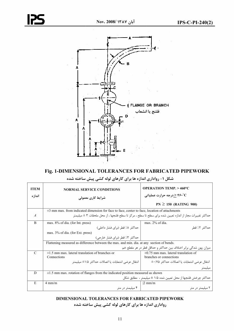
7.2.1 General dimensions such as face to face, face
or end to end, face or end to center and center to
center shall be ±3 mm (see Fig. 1 Item A).
Tolerances shall not be cumulative.
اندازه هاي عمومي نظير سطح تا سطح، سطح رواداري 1- 2- 7
ركزـا مــت ركزـا ، سطح يا انتها تا مركز و مــيا انتها تا انته
اين رواداري را نبايد ) Aاندازه 1شكل . (باشدميليمتر ±3 بايد
. رت مجموع در نظر گرفتبه صو
7.2.2 Flange bolt holes shall straddle to vertical,
horizontal or North-South centerline unless
otherwise noted. Rotation of flange bolt holes shall
not exceed 1.5 mm measured across the flange face
parallel to a centerline and between the holes
nearest to it. (See Fig. 1 Item D).
سوراخ هاي فلنج بايد نسبت به محورهاي مركزي، 2- 2- 7
. افقي و عمودي متقارن باشند مگر آن كه غيرآن ذكر شده باشد
ميزان چرخش سوراخهاي فلنج حد فاصل سطح موازي فلنج با
ميليمتر 5/1خط مركزي تا نزديك ترين سوراخها به آن نبايد از
)Dاندازه 1شكل . (تجاوز نمايد
7.2.3 Inclination of flange face from true position,
in any direction shall be 4 mm per meter. (See Fig.
1 Item E).
حداكثر انحراف سطح فلنج نسبت به موقعيت حقيقي 3- 2- 7
اندازه 1شكل ( .آن در هر جهت بايد چهارميليمتر در متر باشد
E(
7.2.4 Displacement of branch connection from
indicated location shall be ±1.5 mm. (see Fig. 1
Item C).
5/1حداكثر جابجايي انشعاب از محل تعيين شده بايد 4- 2- 7
)Cاندازه 1شكل (ميليمتر باشد
Nov. 2008/ 1387آبان
IPS-C-PI-240(2)
11
Fig. 1-DIMENSIONAL TOLERANCES FOR FABRICATED PIPEWORK
رواداري اندازه ها براي كارهاي لوله كشي پيش ساخته شده - 1شكل
ITEM
اندازه
NORMAL SERVICE CONDITIONS
معمولي كاريشرايط
OPERATION TEMP. > 460°C
C˚460 < درجه حرارت عملياتي
PN ≥ 150 (RATING 900)
A
±3 mm max. from indicated dimension for face to face, center to face, location of attachments
ميليمتر ± 3 ملحقاتمحل فلنجها ، از تغييرات مجاز از اندازه تعيين شده براي سطح تا سطح ، مركز تا سطح حداكثر
B max. 8% of dia. (for Int. press) )براي فشار داخلي(قطر % 8حداكثر
max. 3% of dia. (for Ext. press) )براي فشار خارجي(قطر % 3حداكثر
max. 2% of dia. قطر% 2حداكثر
Flattening measured as difference between the max. and min. dia. at any section of bends.
شدگي برابر اختالف بين حداكثر و حداقل قطر در هر مقطع خم پهنميزان
C ±1.5 mm max. lateral translation of branches or
Connections
ميليمتر ±5/1اتصاالت حداكثر ياانتقال عرضي انشعابات
±0.75 mm max. lateral translation of
branches or connections ±75/0اتصاالت حداكثر يا انتقال عرضي انشعابات
ميليمتر
D ±1.5 mm max. rotation of flanges from the indicated position measured as shown مطابق شكل ، ميليمتر ± 5/1حداكثر چرخش فلنجها از محل تعيين شده
E 4 mm/m يليمتر در مترم 4
|2 mm/m ميليمتر در متر 2
DIMENSIONAL TOLERANCES FOR FABRICATED PIPEWORK
براي كارهاي لوله كشي پيش ساخته شدهاندازه ها رواداري
يا انشعاب فلنج
Nov. 2008/ 1387آبان
IPS-C-PI-240(2)
12
7.3.2 The toes of adjacent circumferential butt
welds shall be no closer than four times the
nominal thickness of the pipe, in the case of DN
300 (NPS 12) and below, with a minimum
acceptable separation of 50 mm. For nominal
diameter greater than DN 300 (NPS 12) the
minimum acceptable separation shall be 100 mm.
ين ، يبه پا )اينچ 12( 300با قطر اسمي در لوله هاي 3-2- 7
50فاصله لبه هاي دو جوش محيطي لب به لب بايد حداقل
ر ضخامت اسمي لوله نبايد بهم ميليمتر بوده و از چهار براب
12( 300قطر اسمي براي لوله هاي بزرگتر از. نزديكتر باشند
.ميليمتر مي باشد 100حداقل فاصله مجاز دو جوش )اينچ
7.4 Welding
7.4.1 Prior to the start of welding, a distance of 50
mm from the weld edge shall be thoroughly
cleaned of any contaminants (e.g. oil, grease, and
NDT materials) which may adversely affect the
weld quality. The weld area shall be scratch-
brushed using a stainless steel wire brush
followed by solvent cleaning. All cleaning fluids,
solvents etc. Shall be halide-free and non-
injurious to the materials being cleaned and shall
be applied with lint-free cloth.
جوشكاري 4- 7
ميليمتر از طول لوله از 50قبل از شروع جوشكاري ، 4-1- 7
روغن، گريس، و مواد (محل لبه جوش بايد از هرگونه آلودگي
تميز شوند تا اثر بد در ) به كار رفته در آزمايشهاي غير مخرب
سطح جوش بايد اول با برسي از جنس . كيفيت جوش نگذارد
. الل مناسب تميز گرددفوالد ضد زنگ تميز شده و بعد با ح
مايعات تميزكننده و حاللها نبايد داراي تركيباتي از هالوژن و
عناصري با بار الكتريكي مثبت و يا موادي كه به جنس لوله
براي كار با اين مواد بايد از پارچه بدون پرز. صدمه ميزنند باشد
.استفاده شود
7.2.5, The difference between maximum and
minimum diameter at any cross section of bends
performed by the Executor shall not be more than
8% of diameter for internal pressure and more
than 3% of diameter for external pressure; see Fig.
1, Item B in this respect.
در مورد لوله هائي كه مجري در محل خم ميزند 5- 2- 7
نبايد هر مقطع از خماختالف بين حداقل و حداكثر قطر در
درصد 3قطر براي فشار داخلي و بيشتر از درصد 8بيشتر از
)Bشكل يك اندازه (براي فشار خارجي باشد
7.3 Pipe Joints
7.3.1 Longitudinal seams in adjoining lengths of
welded pipe shall be staggered over a distance of
at least 5 times the wall thickness of pipe
measured over the circumference of the pipe or by
approximately 30 degree off-set, so that they do
not form a continuous line at a butt welding joint.
Longitudinal welds should be located at the top,
90 degree of the pipe spool and shall also clear
branch connections and other welded
attachments..
اتصال لوله ها 3- 7
براي جوش دادن دو لوله داراي درز جوش طولي بايد 3-1- 7
ابر ضخامت لوله در محل جوش و يا دو درز به اندازه پنج بر
درجه از هم فاصله داشته باشند به طوري كه دو 30 تقريباً
.گيرندندرز جوش در يك خط قرار
درجه فوقاني لوله º90درز جوشهاي طولي بايستي در قسمت
قرار گيرند و هيچگونه انشعاب يا اتصال جوشي روي آنها قرار
.نگيرند
7.4.2 End preparation, alignment and fit-up of
pipe pieces to be welded, preheating, welding,
post heating, inspection and post weld heat
treatment shall conform to this Standard and IPS-
C-PI-290.
ها، جفت كردن و هم محوري لوله ،ها آماده سازي لبه 4-2- 7
كاري، پس گرمي، بازرسي و عمليات حرارتي پيش گرمي، جوش
استاندارد اين استاندارد و زاماتبعد از جوشكاري بايد طبق ال
IPS-C-PI-290 .
7.4.3 Insulation shoes, anchors, guides, support
clips, insulation anti-slip bars, miscellaneous
brackets and welded attachments shall be welded
before heat treatment. Fabrication of insulation
shoes shall be as per relevant standard drawing.
هاي هاي عايق، مهارها، راهنماها، گيره كفشك 4-3- 7
هاي متفرقه و هاي ضد لغزش عايق، بست هاي، ميله تكيه
كاري اتصاالت جوش شده بايد پيش از عمليات حرارتي جوش
ي استاندارد هاي عايق بايد براساس نقشه اخت كفشكس. شوند
.مربوطه انجام گيرد
Nov. 2008/ 1387آبان
IPS-C-PI-240(2)
13
7.4.4 Branch and non-pressure part attachment
welds should not cross longitudinal seams or
circumferential butt welds and shall be subject to
the toe to toe separation distance specified for
circumferential butt welds.
Where such intersections are unavoidable the main
weld shall be subject to non-destructive
examination prior to making the attachment weld.
The extent of examination shall be at least twice
the diameter of the branch pipe measured from the
center line of the branch.
تقاطع جوش انشعابات و يا قطعاتي كه تحت فشار 4-4- 7
نيستند با درز جوش طولي يا جوشهاي محيطي لوله توصيه
لبه هاي دو جوش بايد به مقدار مشخص شده براي . نميشوند
.جوشهاي لب به لب محيطي از هم فاصله داشته باشند
هائي كه تقاطع اين جوشها اجتناب ناپذير است قبل از در محل
مخرب ، جوش اصلي بايد تحت آزمايش غيراتصالجوشكاري
گيرد طول جوشي كه تحت اين آزمايشات قرار مي. قرار گيرد
.ور اصلي انشعاب حداقل دو برابر قطر انشعاب باشدــبايد از مح
7.4.5 Joints involving the intersection of more than
two welds shall be avoided.
االتي كه با بيش از دو جوش برخورد از جوشكاري اتص 4-5- 7
.دارند بايد اجتناب نمود
7.4.6 Joints to be seal welded shall be made up
clean and without the use of tape or any compound.
Welding shall be performed in accordance with the
qualified procedure by a qualified welder. All
exposed threads shall be covered by the seal weld.
اتصاالتي كه با جوش آب بندي مي شوند بايد تميز 4-6- 7
جوشكاري بايد . شده و عاري از نوار و خمير آب بندي باشند
يد شده انجام پذيرد و ياشده توسط جوشكار تتاييد طبق روش
.وندكليه رزوه هاي غير درگير بايد با جوش پوشانده ش
7.4.7 Reinforcing pads shall not be installed except
where called for on spool drawings. Basic material
shall be the same as the pipe material unless
otherwise approved in writing. Fabrication details
shall be in accordance with ASME code. Drawings
will specify diameter and pad thickness. It is
preferable to have padded shapes the same but pad
size may be altered provided equivalent cross-
sectional area is maintained and code requirements
are met.
كننده به جز در جاهايي كه به هاي تقويت بالشتك 4-7- 7
ي اصلي ماده. هاي اسپول احتياج است نبايد نصب شوند قشهن
ي لوله باشد مگر آن كه غير آن كتباً تاييد بايد از جنس ماده
. باشد ASMEجزئيات ساخت بايد مطابق كد . شده باشد
ترجيحاً . كنند ها قطر و ضخامت بالشتك را مشخص مي نقشه
اما شوند، هاي يكسان در نظر گرفته مي هاي بالشتك شكل
تواند متغير باشد مشروط بر آن كه سطح ي بالشتك مي اندازه
.مقطع مجاز رعايت شود و الزامات كد را برآورده سازد
7.5 Screwed Piping (Threaded Joints)
7.5.1 If threading of piping is performed, the
threads shall be standard taper pipe threads,
concentric with the pipe in accordance with
ASME B1.20.1.
)اي اتصاالت رزوه(لوله كشي با اتصاالت دنده اي 5- 7
، رزوه ها و نيز دنده ها ورت رزوه كاري لوله هادر ص 1- 5- 7
و هم مركز با لوله طبق بايد از نوع مخروطي استاندارد
.اجرا شوندASME B1.20.1 استاندارد
7.5.2 Screwed pipe joints shall be seal welded
when called for in standard specification for
piping material IPS-E-PI-221 or as indicated on
the piping Isometric drawings except normally for
control valves, gauge glasses, level controllers and
alarms, thermo wells, pressure gauge, union nuts,
drain valve, outlet plugs or caps, vent plugs or
caps, steam traps, screwed relief valves.
كشـــي هنگامـي كه مشخصـات اسـتاندارد لوله 2- 5- 7
IPS–E–PI-221 هاي ايزومتريك مدنظر باشد يا وقتي در نقشه
بايد با ) اي رزوه(اي ي دنده كشي اشاره شود اتصاالت لوله لوله
ها، بندي شوند؛ به جز مواردي شامل مهره ماسوره جوش آب
ها يا هاي خروجي، توپي ها يا سرپوش شيرتخليه، توپي
نان هاي هواگيري، تله هاي بخار و شيرهاي اطمي سرپوش
.بندي شوند ؛ بايد با جوش آب)اي رزوه(اي دنده
7.5.3 During assembly of threaded joints, all
threads of pipes and fittings shall be thoroughly
cleaned of cuttings, dirt, oil or any other foreign
matter.
ي ه دنده هاي رواالت پيچي كلياتص در هنگام بستن 3- 5- 7
لوله و اتصاالت بايد كامالً تميز و عاري از هرگونه براده فلزات
.خاك، روغن يا هر ماده خارجي ديگري عاري و تميز باشد
7.5.4 A thread compound or lubricant shall be 7 -5 -4 به غير از اتصاالتي كه با جوش آب بندي خواهند شد
Nov. 2008/ 1387آبان
IPS-C-PI-240(2)
14
used for all assemblies except where seal welded,
in particular to prevent galling with stainless steel
bolting. It shall be suitable for the service
conditions and not react unfavorably with the
service fluid, the bolts, gaskets or piping material.
يري از اي مخصوصاً جهت جلوگ براي بستن بقيه اتصاالت رزوه
هاي فوالد زنگ نزن، بايد از روان سازي هاي رزوه كچلي رزوه
استفاده نمود اين مواد بايد مناسب با شرايط عملياتي بوده و به
سيال داخل لولــه، پيچ و مهره ها، واشرها يا جنس لوله توليد
.تركيب نامطلوب ننمايد7.5.5 Minimum joint make-up shall be based on the
following “Normal Engagement” table: درگيري "حداقل ساخت اتصال بايد براساس جدول 5- 5- 7
:زير انجام شود "طبيعي
NPS 1/8 1/4 3/8 1/2 3/4 1 1¼ 1½ 2
N.E 6mm 10mm 10mm 13mm 14mm 17mm 17mm 17mm 19mm
7.5.6 Seal welding shall cover the exposed pipe
threads at screwed fittings but shall not exceed 10
mm fillet.
ي درگير هاي لوله بندي شده بايد دندانه جوشكاري آب 6- 5- 7
ي جوش نبايد از اي پوشش دهد اما ماهيچه را در اتصاالت رزوه
.ميلي متر بيشتر شود 107.5.7 Temporary vent plugs which have been
temporary utilized for pressure test and/or
cleaning/blowing of piping shall be seal welded
after completion of relevant work.
هاي هواگيري موقت كه به طور مقطعي براي در پوش 7- 5- 7
كشي به كار هوادهي در لوله/ يا تميزكاري / آزمون فشار و
بندي روند بايد پس از اتمام عمليات مربوطه با جوش آب مي
.شوند
7.6 Flanged Joints
7.6.1 All flange facings shall be true and
perpendicular to the axis of pipe to which they are
attached.
اتصاالت فلنجي 6- 7
كليه سطوح فلنج ها بايد سالم و عمود بر محور لوله اي 6-1- 7
.باشند كه به آن متصل شده است
7.6.2 Slip-on flanges, when specified and reducing
flanges shall be welded both inside and outside. If
the inside weld extends beyond the face of the
flange, it shall be finished flush. Flange faces shall
be free from weld spatter, mars and scratches.
ر و ماده و فلنجهاي كاهنده بايد از داخل و فلنج هاي ن 6-2- 7
اگر جوش داخلي به سطح فلنج نفود . خارج جوشكاري شوند
سطوح . كند اين مقدار جوش بايد از سطح فلنج برداشته شود
فلنج ها بايد عاري از هرگونه پاشش جوش ، كندگي ،برآمدگي
.و خراشيدگي باشد
7.6.3 Orifice flange taps shall be located in the
exact orientation shown on the spool drawing and
the inside surface of orifice flanges shall be made
smooth and clear of any weld spatter that has
penetrated through. The sections of pipe to which
the orifice flanges are attached shall be smooth and
free from blisters and scale.
سوراخ قالويز زده شده فلنج هاي اريفيسي بايد در 6-3- 7
در . جهتي كه در نقشه ها نشان داده شده است قرار گيرد
صورت پاشش ذرات جوش به داخل فلنج روزنه اي بايد اين
. پاشش برطرف شده و سطح داخلي كامالً صيقل و تميز باشد
له كه فلنج روزنه اي به آن متصل مي شود قسمت هائي از لو
.بايد صيقلي و عاري از هرگونه تاول و پوسته باشد
7.7 Branch Connections
Branch connection and its reinforcement shall be
in accordance with piping plan and isometric
drawings as stated in IPS-E-PI-240.
اتصال انشعابات 7- 7
اتصال انشعابات و صفحه تقويتي آنها بايستي طبق نقشه هاي
انجام IPS-E-PI-240پالن و ايزومتريك و مطابق با استاندارد
.شوند
7.8 Cutting and Trimming of Standard Fittings
Fittings like elbows, coupling, etc., shall be cut /
trimmed wherever required to meet fabrication and
erection requirements, as per drawings or
برش و آراستن اتصاالت استاندارد 8- 7
اتصاالتي نظير زانو، كاپلينگ و نظاير آن هرجا الزم باشد بايد
ها و يا نقشهبراي مطابقت با نيازهاي توليد و نصب طبق
Nov. 2008/ 1387آبان
IPS-C-PI-240(2)
15
instructions of the Engineer. دستورات نماينده كارفرما بريده و آراسته شوند.
7.9 Jacketed Piping
The Pre-assembly of jacketed elements to the
maximum extent possible shall be accomplished at
shop by the Executor.
Position of jump overs and nozzles on the jacket
pipes, fittings, etc., shall be marked according to
pipe disposition and those shall be prefabricated to
avoid damaging of inner pipe and obstruction of
jacket space.
لوله هاي دوجداره 9- 7
تا حداكثر امكان مجري بايد لوله هاي دوجداره را در كارگاه به
.نمايدپيش ساخت تهيه صورت
ها و اتصاالت دوجداره محل لوله هاي اتصالي و نازلها روي لوله
بايد طبق موقعيت لوله عالمتگذاري شوند و جهت پرهيز از
صدمه ديدن لوله داخلي و گرفتگي فضاي بين دو لوله بايد
.پيش ساخت شوند
7.10 Shop-Fabrication/Pre-Fabrication
Piping spools, after fabrication, shall be stacked
with proper identification marks, so as to facilitate
their withdrawal at any time during erection.
During this period all flange faces (gaskets contact
surfaces) and threads shall be adequately protected
by coating with a removable rust preventive
material. Care shall also be taken to avoid any
physical damage to flange faces and threads.
پيش ساخت/ساخت در كارگاه 10- 7
كليه قسمتهاي سيستم لوله كشي كه قبالًدر كارگاه پيش ساخت
مي شوند بايد به طوري عالمت گذاري شوند كه در موقع نصب
كليه سطوح فلنج ها . ان آنها را پيدا و نصب نمودبه راحتي بتو
و دنده هاي روي لوله ها ) سطح تماس آنها با واشرهاي آببندي(
محافظت شوند به به وسيله مواد ضد زنگ پاك شدنيبايستي
.طوري كه صدمه به سطح فلنج ها و دنده ها وارد نشود
7.11 Piece Marking
7.11.1 Each fabricated spool piece shall have a
mark number painted adjacent to 50 mm wide
color bands running completely around the pipe,
except that for austenitic chrome nickel, nickel, or
high nickel alloy, the painted mark number shall be
replaced by a metal tag securely attached to the
pipe with metal straps.
شماره گذاري قطعات پيش ساخته 11- 7
روي تمام قطعات پيش ساخته شده در كنار كد رنگ 1- 11- 7
ميليمتر دور تا دور لوله اعمال 50 كه جهت شناساني به عرض
بجزشده است بايد شماره شناسائي نيز با رنگ نوشته شود،
رم و نيكل، نيكل، ك نتيزنگ نزن آستيهاي از جنس فوالد لوله
كه به جاي نوشتن شماره قطعه با ،بااليا آلياژهاي داراي نيكل
هاي فلزي كه محكم با نوار فلزي به لوله رنگ بايد از برچسب
.نمودشوند استفاده بسته مي
7.11.2 Piece mark numbers and field welds for
shop/field fabricated pipe spool pieces are
indicated on spool drawings. Pieces are to be
sectionalized dimensions suitable for transportation
and erection. In case of sea transportation and
inland transportation, the case size, for packing
shall be as per separate procedure for
transportation.
هاي در محل براي هاي عالمت قطعه و جوش شماره 2- 11- 7
هاي محل در نقشه/ي ساخته شده در كارگاه قطعات اسپول لوله
بندي شده قطعات بايد ابعادي بخش. شوند اسپول مشخص مي
درمورد انتقال دريا . مناسب براي انتقال و ساخت داشته باشند
بايد براساس بندي ي قطعات براي بسته و انتقال خشكي، اندازه
.ي مجزاي انتقال در نظر گرفته شود رويه
7.11.3 Pieces of any one line number shall be
marked consecutively in the direction of flow.
ها بايد در جهت ي خط قطعات هر كدام از شماره 3- 11- 7
.جريان به طور پشت سر هم عالمت گذاري شوند
Nov. 2008/ 1387آبان
IPS-C-PI-240(2)
16
8. FIELD INSTALLATION
8.1 General Consideration
8.1.1 During installation of stress relieved lines,
care must be taken to avoid heating, peening or the
development of stress concentration from any
cause.
محلنصب در -8
عموميمالحظات 8-1
ئي شده اند بايد در موقع نصب لوله هائي كه تنش زدا 8-1-1
دقت شود كه از هرگونه حرارت دادن، ضربه زدن و يا هر عمل
.ديگري كه باعث تمركز تنش در لوله مي شود پرهيز گردد
8.1.2 Before erection, all pre-fabricated spool
pieces, pipes, fittings, etc., shall be cleaned
internally and externally.
لوله ها، اتصاالت و داخلي و خارجيسطوح كليه 8-1-2
سيستم هاي لوله كشي كه پيش ساخت شده اند بايستي قبل
.از نصب كامالً تميز گردند
8.1.3 Piping to be field pickled, sandblasted, etc. as
noted on the spool drawings shall be handled per
IPS-C-PI-410. The Executor shall provide ample
protection on all such cleaned piping to insure that
it will be free and clear from all rust and corrosion
products during the interim period between
installation and start-up.
هاي در محل كه در نقشه. ..اسيد شوئي، ماسه پاشي و 8-1-3
ق استانداردـــص شده بايد طبــش ساخت مشخــپي
IPS-C-PI-410 مجري بايد از اين لوله هاي تميز . انجام شود
شده محافظت كافي به عمل آورد تا در فاصله زماني بين نصب
لوله و راه اندازي از هرگونه زنگ زدگي و خوردگي مصون
.باشند
8.1.4 Piping shall be installed in a manner that
resultant forces on the equipment will be kept to
minimum and particular care shall be taken at
connection joint of pump, compressor and other
mechanical equipment at which piping resultant
forces could cause misalignment.
كشي بايد بگونه اي انجام شود كه برآيند نيروهاي لوله 8-1-4
در محل اتصال . وارده بر تجهيزات متصل به آن به حداقل برسد
به پمپ، كمپرسور و ساير تجهيزات مكانيكي كه در آنها برآيند
هم محوري ميشود بايد دقت نيروهاي وارده باعث بهم خوردن
. اي به عمل آيد ويژه
8.2 Piping Routing
8.2.1 No deviations from the piping route indicated
in drawings shall be permitted without the
approval of the Engineer.
مسير لوله كشي 8-2
بدون اخذ مجوز از نماينده كارفرما هيچ انحرافي از 8-2-1
.مسيرهاي تعيين شده در نقشه ها مجاز نمي باشد
8.2.2 Pipe to pipe, pipe to structures/equipment
distances/clearances as shown in the drawings
shall be strictly followed, as these clearances may
be required for the free expansion of
piping/equipment. No deviations from these
clearances shall be permissible without the
approval of the Engineer.
اندازه هاي داده شده در نقشه ها در مورد فواصل بين 8-2-2
رعايت كامالًبايد تجهيزاتها و يا لوله تا لوله، لوله تا سازه
امكان دارد اين فواصل براي انبساط آزاد لوله يا چون . شوند
هاي داده شده هيچ انحرافي از اندازه. مورد نياز باشد تجهيزات
.بدون كسب مجوز از نماينده كارفرما مجاز نيست
8.2.3 In case of fouling of a line with other piping,
structure, equipment, etc., the matter shall be
brought to the notice of Engineer and corrective
action shall be taken as per his instructions.
در صورت برخورد لوله با ساير قسمت هاي سيستم 8-2-3
ها و نظاير آن بايد موضوع به اطالع لوله كشي، سازه ها، دستگاه
طبق دستورالعمل وي عمليات تصحيح و نماينده كارفرما برسد
.مسير انجام شود
8.2.4 When the term "Field Route" is used on
small screwed piping, the Executor shall route the
piping in a neat and orderly manner consistent with
good piping practice.
در "تعيين مسير در محل نصب"عبارت وقتي 8-2-4
مجري ،اي با قطر كوچك مشخص شده باشد كشي رزوه لوله
از روشي منظم و مرتب و مطابق با اصول در تعيين مسير بايد
.تفاده نمايدلوله كشي اس
8.2.5 Slopes specified for various lines in the
drawings shall be maintained by the Executor.
Corrective action shall be taken by the Executor in
مجري ملزم است كليه شيب هاي داده شده در 8-2-5
اين شيب ها اعمالدر صورتي كه . نقشه ها را مراعات نمايد
Nov. 2008/ 1387آبان
IPS-C-PI-240(2)
17
consultation with the Engineer wherever Executor
is not able to maintain the specified slope. مقدور نباشد، اقدام اصالحي بايد با مشورت نماينده كارفرما به
.عمل آيد
8.3 Cold Spring/Cold Pull
8.3.1 Wherever cold spring is specified in drawing,
the Executor shall maintain the necessary gap.
كشش سرد 8-3
در نقشه ها مشخص شده باشد كشش سردوقتي كه 8-3-1
.مجري بايد فواصل داده شده را رعايت نمايد
8.3.2 Before performing final tie-in the Executor
shall obtain a written confirmation from the
Engineer, indicating that the gap between the pipes
is in accordance with drawing dimensions, which
have been adjusted to compensate for cold spring.
يديه كتبي الزم را يي تايمجري بايد قبل از اتصال نها 8-3-2
صل اجرا شده با آنچه در نقشه ها جهت اجهت مطابقت فو
.را از نماينده كارفرما اخذ نمايد آمده استكشش سرد
8.3.3 If cold spring is not called for, lines shall not
be sprung and forced into place. If prefabricated
piping does not fit, it must be corrected by
straightening and/or rewelding.
نبايد لوله ها را نياز نباشدكشش سرد در صورتي كه 8-3-3
سيستم هاي پيش اگر. با فشار يا كشش در محل قرار داد
ساخته شده مناسب نصب نباشند، بايستي دوباره اصالح و
.جوشكاري شوند
8.3.4 Stress relieving of the weld (if necessary)
shall be performed before removing the gadgets for
cold pulling.
بايد قبل از عملر صورت نياز به تنش زدايي، اين د 8-3-4
كه جهت كشيدن سيستم استفاده شده است ابزاريبرداشتن
.اجرا شود
8.4 Delivery, Handling and Installation of
Expansion Joints
All expansion joints shall be installed in accordance
with following specification and installation
drawings, if any, supplied to the Executor.
تحويل، حمل و نصب اتصاالت انبساطي 8-4
مجري بايــد تمام اتصاالت انبساطــي را طبق الزامات زير و
در صورتي كه در اختيار او گذاشته شده (نقشه هاي اجرائي
.نصب نمايد) باشد
8.4.1 Upon receipt, the Executor shall check for
any damage occurred during transit.
به محض وصول اتصاالت انبساطي، مجري بايد آنها را 8-4-1
.از نظر صدمه ديدن در زمان حمل و نقل بررسي نمايد
8.4.2 The Executor shall bring to the notice of the
Engineer any damage done to the
bellows/corrugations, hinges, tie rods, flanges/weld
ends, etc.
هرگونه صدمه وارده به قسمت آكاردئوني، مجري بايد 8-4-2
مفاصل، ميله هاي نگهدارنده، فلنج ها يا جوش انتهايي و نظاير
. آنرا به كارفرما گزارش نمايد
8.4.3 Each expansion joint shall be blown free of
dust/foreign matter with compressed air or shall be
cleaned with a piece of cloth.
هرگونه گرد و خاك و مواد خارجي روي اتصاالت 8-4-3
انبساطي بايد با فشار هوا زدوده و يا با يك تكه پارچه تميز
.شوند
8.4.4 For handling and installation of expansion
joints, great care shall be taken while slinging. An
expansion joint shall never be slinged on bellows
corrugations/external shrouds, tie rods, angles, etc.
در زمان حمل و نصب اتصاالت انبساطي بايد دقت 8-4-4
محافظ زيادي به عمل آيد كه سيم بكسل جرثقيل روي
گهدارنده و نظاير آن ، ميله هاي نخارجي قسمت آكاردئوني
.بسته نشود
8.4.5 An expansion joint shall preferably be
slinged on the end pipes/flanges or on the middle
pipe.
سيم بكسل بايد ترجيحاً روي لوله يا فلنج انتهايي يا 8-4-5
.روي لوله مياني بسته شود
8.4.6 All expansion joint shall be delivered to the
Executor at "Installation Length" as will be indicated
on the drawings. The "Installation Length" is
يل شده به مجري بايد طول اتصاالت انبساطي تحو 8-4-6
هاي داده شده در نقشه ها باشد و اين طول با مطابق اندازه
Nov. 2008/ 1387آبان
IPS-C-PI-240(2)
18
maintained by means of shipping rods, angles
welded to the flanges or weld ends or by wooden or
metallic stops.
استفاده از ميله هاي نگهدارنده مخصوص حمل ، جوش دادن
چند نبشي به انتهاي فلنجي يا جوشي آن يا توسط
. هاي چوبي يا فلزي ثابت نگهداشته شود نگهدارنده
8.4.7 The pipe ends in which the expansion joint is
to be installed shall be perfectly aligned or shall
have specified lateral deflection as noted on the
relevant drawings.
سر لوله هائي كه اتصال انبساطي بين آنها بايد دو 8-4-7
نصب شود الزم است كامالً هم محور بوده و يا اينكه داراي خيز
.خص شده در نقشه هاي مربوطه باشندجانبي مش
8.4.8 The pipe ends/flanges shall be spaced at
distance which will be specified in the drawings. دو سر لوله ها يا فلنج ها بايد از هم به اندازه اي كه در 8-4-8
.نقشه ها مشخص شده است، فاصله داشته باشند
8.4.9 The expansion joint shall be placed between
the mating pipe ends/flanges and shall be tack
welded/ bolted for checking correct alignment of
the mating pipes.
اتصال انبساطي بايد بين دو سر لوله ها يا فلنج هاي 8-4-9ره متصل به لوله ها قرار گرفته و با نقطه جوش و يا با پيچ و مه
در جاي خود قرار گيرد و سپس همتراز بودن لوله هاي اتصالي .به آن بررسي شوند
8.4.10 After the expansion joint is installed, the
Executor shall ensure that matching pipes and
expansion joint are in correct alignment and that the
pipes are well supported and guided.
پس از اين كه اتصال انبساطي نصب شد، مجري بايد 8-4-10
هاي متصل به اطمينان حاصل نمايد كه اتصال انبساطي و لوله
.آن دقيقاً هم محور بوده و لوله ها داراي نگهدارنده مناسب باشند
8.4.11 The expansion joint shall not have any
lateral deflection. The Executor shall maintain
parallelism rings or bellows convolutions.
مجري . اتصال انبساطي نبايد داراي خيز جانبي باشد 8-4-11
بايد توازي رينگ ها و يا چين خوردگي هاي قسمت آكاردئوني
.را حفظ نمايد
8.4.12 Precaution to be taken during welding
8.4.12.1 For carrying out welding, earthing lead
shall not be attached to the expansion joint.
احتياط هائي حين جوشكاري 8-4-12
در موقع جوشكاري سيم اتصال زمين نبايد به 1- 8-4-12
.اتصاالت انبساطي وصل شود
8.4.12.2 The expansion bellows shall be protected
from arc weld shots and welding spatter. اتصاالت انبساطي بايد در مقابل قوس و پاشش 2- 8-4-12
.ذرات جوش محافظت شوند
8.4.13 When an internal sleeve is provided, the
bellows should be installed in the vertical position
with the sleeve pointing downwards and the
convolutions shall be self-draining.
وقتي اتصال انبساطي مجهز به غالف داخلي باشد 8-4-13
بايد به صورت عمودي نصب گردد بنحوي كه غالف داخلي رو به
پايين قرار گرفته و چين خوردگي هاي قسمت آكاردئوني خود
.تخليه باشد
8.4.14 Insulation
Insulation shall not be applied directly to the
bellows convolutions.
عايق 4-14- 7
قسمت آكاردئوني اتصاالت انبساطي نبايد مستقيماً عايق بندي
.شود
8.4.15 Pressure test
Pressure testing of the system having expansion
joint, shall be performed with the shipping lugs in
position.
These lugs shall be removed after testing and
certification is over.
تست هيدروليكي 8-4-15
هنگام آزمايش فشار سيستم لوله كشي حاوي اتصال انبساطي
. بايد گيره هاي مخصوص حمل اين اتصاالت بسته شده باشند
بعد از انجام آزمايش و صدور گواهينامه اين گيره ها بايستي
.برداشته شوند
8.5 Installation of Flanges
8.5.1 Extra care shall be taken for flange
connections to pumps, turbines, compressors, cold
boxes, air coolers, etc. The flange connections to
ها ب فلنجنص 8-5
فلنجي سيستم لوله كشي به پمپها، در اتصاالت 8-5-1
توربين ها، كمپرسورها، سردكننده ها، كولرهاي هوايي و نظاير
Nov. 2008/ 1387آبان
IPS-C-PI-240(2)
19
this equipment shall be checked for misalignment,
excessive gap, etc., after the final alignment of the
equipment is over. The joint shall be made up after
obtaining approval of the Engineer.
د از نقطه نظر اين اتصاالت باي. دقت زيادي به عمل آيد بايد آن
يا فاصله بيش از حد بين فلنج ها و نظاير آن محور بودنهم
.دناز نماينده كارفرما تكميل گردتاييديه پس از اخذ و بررسي
8.5.2 Temporary protective covers shall be retained
on all flange connections of pumps, turbines,
compressors and other similar equipment, until the
piping is finally connected, so as to avoid any
foreign material from entering this equipment.
جهت جلوگيري از داخل شدن مواد خارجي به داخل 8-5-2
پمپ ها، توربين ها، كمپرسورها و ساير دستگاههاي مشابه بايد
يستم لوله كشي با روكش فلنج هاي آنها تا موقع اتصال به س
.محافظتي موقت مسدود شوند
8.5.3 The Executor shall apply polycot
(Molybdenum disulphide) grease mixed with
graphite powder (unless otherwise specified in
piping classes) on all bolts and nuts during storage,
after erection and wherever flange connections are
broken and made-up for any purpose whatsoever.
اگر در كالس مربوط به سيستم لوله كشي چيزي 8-5-3
مشخص نشده باشد، مجري بايد در موقع نگهداري در انبار، در
زمان نصب و يا هر زماني كه فلنج ها را باز مي نمايد كليه پيچ و
دي سولفايد (كت پوليگريس ه مهره هاي مربوطه را ب
.مخلوط به پودر گرافيت آغشته نمايد) وليبدنيمم
8.5.4 On lines and equipment where the operating
pressure of hydrogen (H2) mixtures will be 2.07
MPa (300 psig) and over, bolts shall be tightened
using torque spanners. Any necessary retorquing
shall be carried out after the line is put in service.
حاوي كه در سيستم هاي لوله كشي و تجهيزاتي 8-5-4
07/2 ســيال محــتوي هيــدروژن با فشــار باالتـر از
) گيري شده اندازه –يوند برانج مربع 300(مگاپاسگال مطلق
ار درجه بندي شده بسته ها بايد با آچ پيچ و مهره باشند كليه
پس از در سرويس قرار گرفتن سيستم در صورت لزوم . شوند
.دوباره بايد اين پيچها آچار كشي شوند
8.6 Installation of Valves
8.6.1 Valves shall be installed with
spindle/actuators orientation/position as shown in
the lay-out drawings. In case of any difficulty in
doing this or if the spindle orientation/position is
not shown in the drawings, the Engineer shall be
consulted and work should be done as per his
instructions. However, the location of the valve
hand wheel and/or stem shall not obstruct
walkways or platforms.
In determining valve stem position the following
points shall be considered:
نصب شيرها 8-6
موقعيت، /شيرها بايد طوري نصب شوند كه جهت 1- 8-6
در .ي باشديطبق نقشه هاي جانما آنهاعمل كننده /دسته
مشخص ييماموقعيت دسته در نقشه هاي جان/صورتي كه جهت
نماينده دبايمشكل باشد طبق نقشهنشده و يا اجراي آن
مورد مشورت قرار گرفته و طبق از اين امر مطلع شدهكارفرما
يا چرخ فلكهبهر حال محل . دستورالعمل وي كار انجام شود
ساقه شير نبايد با محل تردد افراد يا سكوها برخورد داشته
.باشد
:به نكات زير بايد توجه شود در تعيين موقعيت ساقه شير
8.6.1.1 No horizontally positioned stems in low-
temperature service is allowed.
ين ساقه شير نبايد يدر سرويسهاي با درجه حرارت پا 1- 1- 8-6
.ي قرار گيردقبه صورت اف
8.6.1.2 Butterfly valves shall not be installed with
the spindle in the vertical position for services
where collection of dirt in the lower shaft bearing
could occur.
ي كه امكان يمحور شيرهاي پروانه اي در سرويسها 2- 1- 8-6
جمع شدن آشغال در پائين نشيمنگاه آنها وجود دارد، نبايد در
.موقعيت عمودي نصب شوند
8.6.1.3 To avoid accidental blocking owing to a
loosened wedge, gate valves installed around
safety/relief valves and in flare lines shall be
positioned with the stem pointing horizontally.
به منظور اجتناب از گرفتگي شيرهاي دروازه اي به 3- 1- 8-6
رهايي كه در طرفين علت شل بودن دروازه آن، ساقه شي
شيرهاي ايمني و يا تقليل فشار روبروي خطوط مربوط به مشعل
. ه اند بايد بصورت افقي نصب گردندنصب شد
Nov. 2008/ 1387آبان
IPS-C-PI-240(2)
20
8.6.2 Care shall be exercised to ensure that globe
valves, check valves and other uni-directional
valves are installed with the flow direction arrow
on the valve body pointing to the right direction. If
the directional arrow is not marked on such valves,
this shall be done in the presence of the Engineer
before installation.
و يكطرفه و تنظيم جرياندر موقع نصب شيرهاي 2- 8-6
يد دقت نمود كه جهت فلش روي ساير شيرهاي يك جهته با
اگر روي بدنه جهت . منطبق باشد با جهت جريان بدنه شير
قبل از نصب بايستي در حضور جريان مشخص نشده باشد،
.نماينده كارفرما جهت جريان بر روي شير مشخص گردد
8.6.3 Fabrication of stem extensions, locking
arrangements and interlocking arrangements of
valves shall be carried out as per
drawings/instructions of the Engineer.
، پيش بيني قفل و وابستگي شيرها افزايش طول ساقه 3- 8-6
هاي مربوطه و يا بايد طبق نقشهوضعيت شيرها بيكديگر
.دستورالعمل نماينده كارفرما انجام پذيرد
8.6.4 In installation of socket welding or seal
welding of ball valves, care shall be taken to avoid
damage to the valve seats.
در موقع جوشكاري شيرهاي توپي نر و ماده اي و يا 4- 8-6
اي ايد دقت شود صدمهـبندي مي شوند ب ا جوش آبي كه بيآنها
.وارد نيايد به نشيمنگاه شيرها
8.6.5 Valve requiring special trim and/or packing
will be so noted in P & ID / Isometric drawings and
contractor shall take care to install this type of
valve only.
يا / و) آراستگي(بري در خصوص شير نيازمند زائده 5- 8-6
/ P&IDبايست همانند آن چه در بندي خاص مي بسته
هاي ايزومتريك آمده است عمل شود و پيمانكار بايد فقط نقشه
.از اين گونه شيرها نصب كند
8.7 Installation of Instrument and Related Piping
8.7.1 Installations of in-line instruments (i.e.
thermowells restriction orifices, safety valves,
control valves, rotameters, orifice flange assembly,
venturimeters, flow meters, etc.), shall form part of
piping erection work. They shall be installed
according to IPS-C-IN-100 and other relevant
standard drawings.
مربوطه نصب ابزار دقيق و لوله كشي 8-7
چاهك شامل (تم لوله كشي نصب ابزار دقيق روي سيس 1- 8-7
شيرهاي شيرهاي ايمني، دودكننده،هاي مح روزنه ،گرمايي
دار هروزن ايه چ، مجموعه فلنها دورسنجكنترل كننده جريان،
منزله به بايد) و غيره سنج ها، جريان اي شيپوره هايعت سنجسر
قلمداد گرديده و كشي قسمتي از عمليات نصب سيستم لوله
هاي استاندارد و ساير نقشه IPS-C-IN-100استاندارد مطابق
.نصب شوند مرتبط
8.7.2 Care shall be exercised and adequate
precautions taken to avoid damage, and entry of
foreign matter into instruments during
transportation, installation and testing.
پيش بيني و دقت الزم بايد به عمل آيد كه در موقع 2- 8-7
نصب و آزمايش ابزارهاي دقيق هيچگونه صدمه اي به ،حمل
ونه جسم خارجي به داخل آنها گآنها وارد نيايد و از ورود هر
.جلوگيري شود
8.7.3 Instrument air piping
These piping from air header to different field
instruments shall be installed with the following
considerations.
لوله كشي هواي ابزار دقيق 3- 8-7
لوله هاي ارتباطي از لوله اصلي هوا به كليه ابزارهاي دقيق نصب
شده در قسمتهاي مختلف بايد با در نظر گرفتن موارد زير نصب
:شوند
8.7.3.1 Where threaded connections are not seal
welded they shall be sealed by the use of thread
compound or P.T.F.E. (Poly-Tetra-Fluor-Ethylene)
known as Teflon tape. P.T.F.E. tape shall not be
used where temperatures exceed 230°C (450°F).
Wherever thread compound is used on screwed
fittings it should be applied to the male thread only.
ي كه اتصاالت رزوه اي با جوش آب يها در محل 1- 3- 8-7
بندي نشده اند بايد از خمير آب بندي يا نوار تفلون استفاده
درجه سانتيگراد 230 اگر درجه حرارت عملياتي بيش از. نمود
در . فلون استفاده نمودباشد نبايد از نوار ت )درجه فارنهايت 450(
صورت استفاده از خمير آب بندي اين خمير فقط روي دنده
.هاي خارجي اعمال گردد
Nov. 2008/ 1387آبان
IPS-C-PI-240(2)
21
8.7.3.2 All pipe ends shall be cut square, reamed of
all burrs and cleared of all foreign material. بريده و قائمانتهاي كليه لوله ها بايد به صورت 2- 3- 8-7
.از هرگونه پليسه بوده و از هرگونه مواد خارجي تميز شوندعاري
8.7.3.3 Cutting oil shall be used in cutting all
threads on galvanized pipe.
زني لوله هاي گالوانيزه بايد از روغن هدندر موقع د 3- 3- 8-7
.استفاده شود
8.8 Vents and Drains
High point vents and low point drains shall be
provided as per the instructions of the Engineer,
even if these are not shown in the working
drawings. The details of vents shall be as per piping
material specifications.
انشعابات هواگيري و تخليه 8-8
ه باشند بايد حتي اگر در نقشه هاي اجرائي مشخص نشد
انشعابات هواگيري در باالترين نقطه و انشعابات تخليه در
ترين نقطه سيستم طبق دستورالعمل نماينده كارفرما ينيپا
جزئيات اتصاالت هواگيري بايد منطبق بر . تعبيه شوند
.مشخصات مواد سيستم لوله كشي باشد
8.9 Pump, Compressor and Steam Turbine Piping
8.9.1 Piping terminations at pumps or compressors
shall be installed so that mating flanges are parallel,
concentric, and in contact prior to bolting the
piping in place.
سيستم هاي لوله كشي پمپ، كمپرسور و توربين 8-9
بخار
شوند مي منتهي ي كه به پمپ ها يا كمپرسورهايلوله ها 8-9-1
بايد طوري نصب شوند كه فلنج هاي اتصالي موازي، هم مركز و
.با هم در تماس باشند و سپس پيچ و مهره هاي آنها بسته شوند
8.9.2 Auxiliary piping shall be neatly routed along
the baseplate and shall not extend across the
operating floor. This piping shall not obstruct
operation handling and inspection covers, bearing
caps, upper halves of casing, etc.
لوله هاي جانبي اين دستگاهها بايددر اطراف صفحه 8-9-2
بستر آنها به صورت مناسب مسير داده شده و از صفحه بستر
پمپاژ و اين لوله ها نبايد مانعي براي عمليات. بيرون زند
هاي بازرسي، سرپوشهاي نشيمنگاه محور دستگاه، قسمت دريچه
.فوقاني بدنه و نظاير آن ايجاد نمايند
8.9.3 Lub. oil lines shall be separated from hot
process and hot utility lines in order to avoid a fire
hazard, e.g. auto-ignition at 260-320°C.
منظور جلوگيري از خطر آتش سوزي، روغن بايد از به 8-9-3
براي (لوله هاي عملياتي و سرويسهاي جانبي داغ جدا باشد
تا 260درجه حرارتمثال آتش گرفتن خود به خود در محدوده
).درجه سانتيگراد 320
8.9.4 The temporary strainers shall be installed as
close to the machinery as possible for initial start-
up and commissioning.
براي شروع بكار اوليه و راه اندازي دستگاه صافي هاي 8-9-4
.موقتي بايد تا حد امكان نزديك به دستگاه نصب شوند
8.10 Piping Through Walls and Concrete Floors
Sleeves or holes through walls, floors of buildings
and table tops shall have a size permitting the
passage of a flange of the relevant pipe size, to
facilitate the installation of prefabricated piping and
to permit insulating work.
Holes through walls and floors shall be sealed after
piping installation.
ه كشي از ميان ديوارها و كف بتنيلول 8-10
غالف يا سوراخهاي تعبيه شده در ديوارها، كف ساختمانها و
صفحات فوقاني بايد به اندازه اي باشند كه اجازه عبور فلنج
مربوط به اندازه لوله عبوري را بدهد تــا نصب سيستم هاي
.كشي پيش ساخته شده و عايق كاري آنها را تسهيل نمايد لوله
از نصب سيستم لوله كشي سوراخهاي روي ديوارها و پس
.كف ها بايد آب بندي شوند
8.11 Buried Piping
8.11.1 Buried piping shall be kept at a distance
from electric power, lighting and instrument signal
cables as instructed by the Engineer.
يلوله كشي زيرزمين 8-11
لوله هاي مدفون بايد در فاصله مناسبي از كابلهاي 1- 8-11
فشار قوي برق، روشنايي و كابلهاي ابزار دقيق مطابق با
. العمل نماينده كارفرما قرار داده شوند دستور
Nov. 2008/ 1387آبان
IPS-C-PI-240(2)
22
8.11.2 For buried piping system the Executor shall
excavate and maintain the trench in which the
piping system is to be laid.
مجري بايد نسبت به كندن و نگهداري كانال براي 2- 8-11
.لوله هاي مدفون اقدام نمايد
8.11.3 The trench shall be sufficiently wide for the
pipe to be laid without damaging the pipe
protective coating. The minimum trench width shall
not be less than pipe diameter plus 400 mm.
عرض كانال لوله بايد به اندازه اي باشد كه بتوان بدون 3- 8-11
آنكه صدمه اي به پوشش محافظتي لوله برسد آن را در كانال
ميليمتر 400اين عرض نبايد كمتر از قطر لوله به عالوه . خواباند
.باشد
8.11.4 The trench shall be excavated to a minimum
depth of 200 mm below the bottom of the pipe and
the full width of trench shall be graded and padded
with sand or other suitable material approved by the
Engineer.
200عمق كانال لوله بايد به حدي باشد كه حداقل 4- 8-11
كف كانال بايد شيب بندي شده و . بماندميليمتر زير لوله خالي
نماينده تائيدبا استفاده از ماسه يا ساير مواد مناسب مورد
.كارفرما كوبيده شود
8.11.5 The sides of the trench shall be free of rock,
loose stones, blasting debris or other spoil likely to
fall or be dislodged, blown or swept under, around
or on top of the pipe.
ديوارهاي كانال لوله بايد فاقد قلوه سنگ، سنگهاي 5- 8-11
لق، ته مانده مواد انفجاري و ساير مواد زايدي باشد كه درحال
افتادن و يا جابجا شدن و يا ريزش در زير و رو و اطراف لوله
.هستند
8.11.6 Where Rock shield or similar overwrap is
used in accordance with IPS-C-TP-274. The 100
mm depth of padding may contain loose gravel and
rock fragments provided that in the opinion of the
Engineer, no damage to the coating would result
from the inclusion of such gravel and rock
fragments.
در صورت استفاده از محافظ در مقابل سنگ يا پوشش 6- 8-11
يكصد ميليمتر از IPS-C-TP-274مشابه طبق استاندارد
قسمت كوبيده شده مي تواند شامل سنگ ريزه و خورده سنگ
باشد، مشروط بر اينكه مطابق نظر نماينده كارفرما سنگ ريزه يا
. رده سنگ باعث صدمه به روكش لوله شودخو
8.11.7 Protective coating
Buried pipelines shall have protective coating
applied in accordance with IPS-C-TP-274 .
The grade of protective coating will be as specified
in above-mentioned standard.
روكش محافظتي 7- 8-11
كــليه لولـه هاي مدفون بايـــد براساس استــانــدارد
IPS-C-TP-274 داراي روكش محافظتي باشند.
.گريد روكش محافظتي بايد مطابق استاندارد مزبور باشد
8.11.8 Laying
8.11.8.1 All brush, skids, pipe, pipe protectors,
rocks, large clods, sticks, protecting rocks and
other hard objects shall be removed from the
bottom of the trench into which the coated and
wrapped pipeline is to be lowered, so that the
protective coating shall not be punctured or
abraded.
اندن لولهخواب 8- 8-11
تمام برسها، تخته ها، لوله ها، محافظ لوله ها، قلوه 1- 8- 8-11
سنگها، كلوخهاي بزرگ، چوب، صخره هاي حفاظتي و ساير
اشياء سخت از كف كانالي كه لوله پوشش داده شده در آن قرار
گيرد بايد برداشته شوند، تا پوشش لوله ها سوراخ يا ساييده مي
.نشوند
8.11.8.2 Pipe shall normally be lowered into the
trench immediately after the coating and wrapping
has been passed by the Engineer. Wide non-
abrasive slings or belts shall be used at all times in
handling the pipeline.
يد پوشش و روكش يمعموالً بالفاصله پس از تأ 2- 8- 8-11
ها بايد در كانال خوابانده شوند ها توسط نماينده كارفرما لوله ولهل
در تمام مراحل حمل و جابجائي لوله ها بايد از تسمه يا سيم
.بكسل پهن استفاده شود كه باعث خراشيده شدن لوله نشود
8.11.8.3 All coated and wrapped pipe which has
been supported in any manner on padded skids, or
lowering devices, shall be subjected to close
inspection by the Executor to see that the coating is
undamaged before the pipe reaches the bottom of
تمام لوله هاي پوشش و روكش داده شده كه روي 3- 8- 8-11
ين برنده يپايه هاي نرم قرار داده شده اند و يا توسط دستگاه پا
آماده خوابيدن در بستر لوله ها هستند، قبل از رسيدن لوله به
Nov. 2008/ 1387آبان
IPS-C-PI-240(2)
23
the trench. Walking on coated pipe is absolutely
forbidden. Backfilling shall be carried out
immediately after hydrostatic test has been
successfully completed but the executor shall first
option the approval of the Engineer. If any
backfilling is carried out without approval of the
Engineer, he will have the right to require the
Executor to remove the backfill for examination of
the coating and wrapping.
از نظر سالم بودن روكش دقيقاً كف كانال، مجري بايد آنها را
قدم زدن روي لوله هاي روكش شده مطلقاً . بازرسي نمايد
يد تست فشار از نماينده كارفرما يپس از اخذ تأ. ممنوع مي باشد
اگر خاكريزي قبل از . بايد بالفاصله عمليات خاكريزي انجام شود
ري يد نماينده كارفرما اجرا شود او اين حق را دارد كه از مجيتأ
بخواهد خاك را دوباره بيرون بياورد تا پوشش و روكش لوله را
.آزمايش نمايد
8.11.8.4 The initial backfill around the pipe and to
a level of at least 200 mm above the top of the pipe
shall be sand or earth free from loose rock, large
gravel sticks, branches or other rubbish that may
damage the pipe or its coating.
200خاكريزي اوليه اطراف لوله و تا ارتفاع حداقل 4- 8- 8-11
ميليمتر روي لوله بايد عاري از هرگونه قلوه سنگ، قطعات چوب
و شاخه، يا ساير موارد زائد مي باشد كه ممكن است به لوله يا
.پوشش آن صدمه بزند
8.11.8.5 Where Rock shield or similar overwrap is used, the initial backfill may contain loose gravel and rock fragments provided that in the opinion of the Engineer, no damage to the coating would result from the inclusion of such gravel and rock fragments.
وقتي از محافظ در مقابل سنگ يا ساير 5- 8- 8-11
هاي مشابه استفاده مي شود، خاكريزي اوليه ميتواند محافظ
حاوي سنگريزه يا خرده سنگ باشد، مشروط به آن كه به نظر
.نماينده كارفرما اين موارد باعث صدمه به روكش لوله ها نگردد
8.12 Pipe Supports
All supports shall be strictly as per drawings and
IPS-G-PI-280.
تكيه گاه لوله ها 8-12
گاههاي لوله ها بايد كامالً منطبق بر نقشه ها و طبق كليه تكيه
.باشند IPS-G-PI-280استاندارد
8.12.1 All piping shall be adequately supported,
anchored, guided or strutted to prevent undue
vibration, deflection stress or strain on any piping
or equipment, in accordance with relevant standard
drawings as detailed on piping drawings.
ها بايد به طور كافي نگه داشته شوند، كشي تمام لوله 1- 8-12
ست زده شوند تا از ارتعاش مهار گردند، هدايت شوند يا ب
كشي يا ناخواسته، تنش تغيير شكل يا كرنش روي لوله
هاي استاندارد مربوطه كه به طور مطابق نقشه –تجهيزات
.جلوگيري شود -كشي درج شده اند هاي لوله تفصيلي در نقشه8.12.2 All piping shall be completely installed
from origin to terminus before anchoring.
Expansion joints shall be cold set. Shipping bars
shall only be removed after the expansion joint(s)
is installed.
كشي بايد به طور كامل از ابتدا تا انتها قبل تمام لوله 2- 8-12
ي اتصاالت انبساطي بايد مجموعه. از مهاركردن، نصب شود
هاي نگهدارنده مخصوص حمل را فقط پس از يلهم. سرد باشند
.نصب اتصال يا اتصاالت انبساطي بايد جدا كرد8.12.3 Spring hangers for support of lines or
equipment are located and identified on piping
drawings. Adjustment to correct setting shall be
made in the field after each lines has searched
operating temperature. Details of all hangers shall
be submitted and also setting and details, marked
on individual hangers.
گاه خطوط يا تجهيزات در هاي فنري براي تكيه آويزه 3- 8-12
تنظيم در . شوند كشي جانمايي و مشخص مي هاي لوله نقشه
يت صحيح بايد پس از رسيدن هر خط به دماي عملياتي وضع
ها بايد تحويل داده شود و نيز جزئيات تمام آويزه. انجام گيرد
ها و جزئيات، بايد روي هر آويزه به طور مجزا تنظيم
.گذاري شود عالمت
8.13 Winterizing and Steam Tracing
For winterizing and steam tracing reference is
made to IPS-E-PR-420.and IPS-D-PI-126.
آماده سازي براي سرما و لوله كشي بخار براي گرم 8-13
.كردن
كشي بخار براي گرم آماده سازي براي سرما و لوله
و IPS-E-PR-420كردن بايـد منـطبق بر استــانداردهاي
IPS-D-PI-126 انجام پذيرد.
Nov. 2008/ 1387آبان
IPS-C-PI-240(2)
24
8.14 Internal Cleaning
Internal cleaning procedure shall be submitted by
the Executor and approved by the Engineer for the
followings:
تميزكاري داخلي 8-14
براي موارد زير روش اجرائي تميز كاري بايد توسط مجري تهيه
. يد نماينده كارفرما برسد يو به تا
8.14.1 After completion of construction works and
before pressure testing, the inside of piping system
shall be cleaned either mechanically or by flushing.
پس از تكميل كارهاي اجرائي و قبل از آزمايش فشار 1- 8-14
ا تميز هو/داخل لوله ها بايد يا به صورت مكانيكي و يا با آب
.شوند
8.14.2 If so specified in project specification,
chemical cleaning shall be performed after
completion of pressure testing in accordance with
IPS-C-PI-410
در صورتي كه در شرح پروژه مشخص شده باشد 2- 8-14
و پس از IPS-C-PI-410كاري شيميايي بايستي مطابق تميز
. آزمايش فشار انجام شود
8.14.3 Flushing through control valves, plug
valves, safety valves, other special valves,
instrumentation devices, pumps, compressors and
any equipment (which should not be flushed) is not
permitted.
تميزكاري داخل شيرهاي كنترل، شيرهاي توپي، 3- 8-14
شيرهاي اطمينان، ساير شيرهاي خاص، ادوات ابزاردقيقي،
سازي بايست پاك ها، كمپرسورها و هر تجهيزي كه نمي پمپ
.شود مجاز نيست
8.14.4 Construction contractor shall provide
facilities to allow for ample volumes and sufficient
pressure and velocities of flushing fluid, this must
be maintained for sufficient time to clean pipe
lines, prior to issue notification of completion.
پيمانكار اجرايي بايد تسهيالت الزم براي امكان عبور 4- 8-14
فشار و سرعت كافي سيال تميزكننده را حجم فراوان و تامين
سازي خطوط لوله فراهم كند، اين شرايط براي زمان كافي پاك
.پيش از اعالم اتمام كار بايد رعايت شود
8.14.5 All equipment that should not be flushed
shall be blocked off, blinded or disconnected. تميز شوند، بايد مسدود، تمام تجهيزاتي كه نبايد 5- 8-14
.كور يا جدا شوند8.14.6 Spool pieces shall be installed in place of
P.D. meters and strainers during line flushing.
Orifice plates shall be removed during flushing.
مبتني ( P.Dقطعات اسپول بايد در محل ميترهاي 6- 8-14
ها طي عمليات تميزكاري خط نصب و صافي) ربر اختالف فشا
در خالل تميزكاري بايد ) اوريفيس(دار هاي سوراخ ورق. شوند
.برداشته شوند8.14.7 All pre-fabricated pipe spools, fittings, etc.
shall be cleaned internally and externally before
erection.
ي از پيش اي لولهه داخل و خارج تمام اسپول 7- 8-14
.شده، اتصاالت و غيره بايد قبل از نصب تميز شوندساخته
9. INSPECTION AND TESTING
Prior to precommisioning and as the piping
erection progresses the piping installation shall be
inspected to the extent necessary in accordance
with approved specifications prepared based on
related IPS and international codes and standards.
In addition to the inspection to be performed by the
Executor, all work is subject to inspection by the
Engineer or his appointed representative. Such
inspection shall not relieve the Executor of his
responsibilities as specified above.
بازرسي و آزمايش -9
قبل از راه اندازي اوليه و همزمان با پيشرفت عمليات اجرائي
نصب شده بايستي تا حد مورد لزوم نصب لوله كشي، لوله هاي
مربوطه IPSطبق مشخصات تهيه شده بر مبناي استانداردهاي
شده مورد تاييد استانداردهاي بين المللي و و نيز كدهاي
عالوه بر انجام بازرسي توسط مجري، كل . بازرسي قرار گيرند
كار توسط نماينده كارفرما و يا هر بازرسي كه او معرفي مي
نمايد مورد بازرسي قرار ميگيرد و انجام اين بازرسي مسئوليت
.مجري را نسبت به انجام كيفي كار سلب نمي نمايد
9.1 Material Check
All materials shall be checked by the Executor or
his nominee to assure compliance with the project
documents.
بررسي مواد 9-1
مجري يا نماينده او بايد كل مواد مورد استفاده را از نظر
.مطابقت با مدارك پروژه بررسي نمايد
Nov. 2008/ 1387آبان
IPS-C-PI-240(2)
25
9.2 Dimensional Check
Prefabricated pipe shall be dimensionally checked
by the Executor or his nominee against isometric
drawings.
بررسي اندازه ها 9-2
كليه لوله هـــاي پيش ساخته بايد از نظر ابعادي با نقشه هاي
.ايزومتريك توسط مجري يا نماينده او بررسي شوند
9.3 Inspection of Welds
Welds shall be inspected and tested in accordance
with IPS-C-PI-290.
بازرسي جوشها 9-3
بازرسي و آزمايش IPS-C-PI-290جوشها بايد طبق استاندارد
.شوند
9.4 Pressure Test
After completion of all erection works all piping
systems shall be pressure tested in accordance with
IPS-C-PI-350. Executor shall develop pressure test
packages for engineer review and approval prior to
commencing testing.
آزمايش فشار 9-4
كل سيستم لوله كشي بايد طبق پس از اتمام عمليات نصب،
.تحت آزمايش فشار قرار گيرد IPS-C-PI-350استاندارد
مجري بايد قبل از اجراي آزمايش ، روش آزمايش فشار را تهيه
. كرده و جهت بررسي و تاييد به نماينده كارفرما ارائه نمايد
10. PAINTING
10.1 Surface Preparation
Outside surface of piping to be painted shall be
prepared according to IPS-C-TP-101 They shall
always be completely dry and free from burrs, weld
spatter, flux, rust, loose scale, dirt, dust, grease, oil
and other foreign matter before any paint is applied.
رنگ آميزي - 10
آماده سازي سطح 1- 10
سطح خارجي لوله هائي كه بايد رنگ آميزي شوند بايد طبق
قبل از رنگ . آماده سازي شوند IPS-C-TP-101استاندارد
آميزي لوله ها بايد كامالً خشك و عاري از هرگونه پولك، ذرات
ريس، جوش، سرباره جوش، زنگ، جرم، كثيفي، گرد و خاك، گ
.روغن و ساير مواد خارجي باشند
10.2 Color Code
The color of piping system for identifying of
carrying fluid shall be in accordance with Table 3
of IPS-E-TP-100.
كد رنگ 2- 10
طبق لوله ها به منظور تشخيص سيال داخل لوله ها بايد رنگ
.باشد IPS-E-TP-100استاندارد 3جدول شماره
10.3 Field Painting
Field painting of hot and cold Uninsulated lines
shall be as per IPS-C-TP-102.
رنگ آميزي در محل 3- 10
بايد طبق لوله هاي عايق بندي نشده چه سرد و چه گرم
.رنگ آميزي شوند IPS-C-TP-102استاندارد
11. INSULATION
Lines to be insulated will be so noted on spool
drawings and shall be insulated in accordance with
IPS-C-TP-701. 3” and larger hot insulated lines
shall be elevated on shoes to provide continuous
insulation at supports. Care should be taken in
matching face of shoe to pipe and to omit any weld
undercut. On sleeper way omit insulation shoes on
carbon steel lines if the maximum operating
temperature is 345ºC or less, except as follows:
Lines 18" and over must be checked to determine
the need for support point wear plates. Vacuum
lines are excluded and special design required.
عايق كاري -11
لوله هائي كه طبق مشخصات ذكر شده در نقشه هاي پيش
دارند بايد طبق استاندارد ساخت نياز به عايق بندي
IPS-C-TP-701 كاري گرم عايق خطوط .عايق بندي شوند
ها باال برده شوند تا اينچ و باالتر بايد روي كفشك 3داراي قطر
مناسب در اتصال. ها صورت پذيرد گاه كاري پيوسته در تكيهعايق
د جوش بايهرگونه گودافتادگيكفشك به لوله و نيز حذفوجه
روي خطوط هاي عايقي در خصوص تراورس، كفشك. دقت شود
345ي دماي عملياتي اگر بيشينه. كربني را حذف كنيدفوالد
خطوط: گراد يا كمتر باشد؛ مگر در مورد زير ي سانتي درجه
اينچ و باالتر بايد براي تعيين لزوم استفاده از 18داراي قطر
خالً در اين مورد طخطو. هاي مقاوم به سايش كنترل شوند ورق
.استثناء هستند و در اين خصوص به طراحي ويژه نياز است
Nov. 2008/ 1387آبان
IPS-C-PI-240(2)
26
12. COATING
Coating of plant underground piping shall be
applied, inspected and tested in accordance with
IPS-C-TP-274.
پوشش -12
داخل كارخانه بايد طبق استاندارد لوله هاي زيرزمين
IPS-C-TP-274 پوشش ، بازرسي و تست شوند.
13. LINING
Lining of plant piping shall be applied, inspected
and tested in accordance with IPS-C-TP-352.
پوشش داخلي -13
كارخانه بايد طبق استانداردپوشش داخل لوله هاي داخل
IPS-C-TP-352 اجرا، بازرسي و تست شوند