Embed Size (px)
Citation preview
Tottenham Court Road ventilation towersStructural engineering for the Elizabeth line
63TheStructuralEngineer | July 2018
thestructuralengineer.org
Joseph MaltezosMEng, CEng, MICE
Project Engineer, Laing O’Rourke, UK
Construction of the ventilation towers at Tottenham Court Road Elizabeth line station
Tim HarmanMEng, CEng, MICE
Principal Engineer, Laing O’Rourke, UK
Introduction
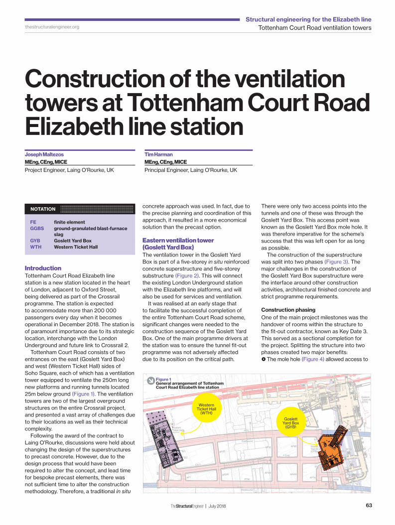
Tottenham Court Road Elizabeth line station is a new station located in the heart of London, adjacent to Oxford Street, being delivered as part of the Crossrail programme. The station is expected to accommodate more than 200 000 passengers every day when it becomes operational in December 2018. The station is of paramount importance due to its strategic location, interchange with the London Underground and future link to Crossrail 2.
Tottenham Court Road consists of two entrances on the east (Goslett Yard Box) and west (Western Ticket Hall) sides of Soho Square, each of which has a ventilation tower equipped to ventilate the 250m long new platforms and running tunnels located 25m below ground (Figure 1). The ventilation towers are two of the largest overground structures on the entire Crossrail project, and presented a vast array of challenges due to their locations as well as their technical complexity.
Following the award of the contract to Laing O’Rourke, discussions were held about changing the design of the superstructures to precast concrete. However, due to the design process that would have been required to alter the concept, and lead time for bespoke precast elements, there was not suffi cient time to alter the construction methodology. Therefore, a traditional in situ
concrete approach was used. In fact, due to the precise planning and coordination of this approach, it resulted in a more economical solution than the precast option.
Eastern ventilation tower (Goslett Yard Box)
The ventilation tower in the Goslett Yard Box is part of a fi ve-storey in situ reinforced concrete superstructure and fi ve-storey substructure (Figure 2). This will connect the existing London Underground station with the Elizabeth line platforms, and will also be used for services and ventilation.
It was realised at an early stage that to facilitate the successful completion of the entire Tottenham Court Road scheme, signifi cant changes were needed to the construction sequence of the Goslett Yard Box. One of the main programme drivers at the station was to ensure the tunnel fi t-out programme was not adversely aff ected due to its position on the critical path.
There were only two access points into the tunnels and one of these was through the Goslett Yard Box. This access point was known as the Goslett Yard Box mole hole. It was therefore imperative for the scheme’s success that this was left open for as long as possible.
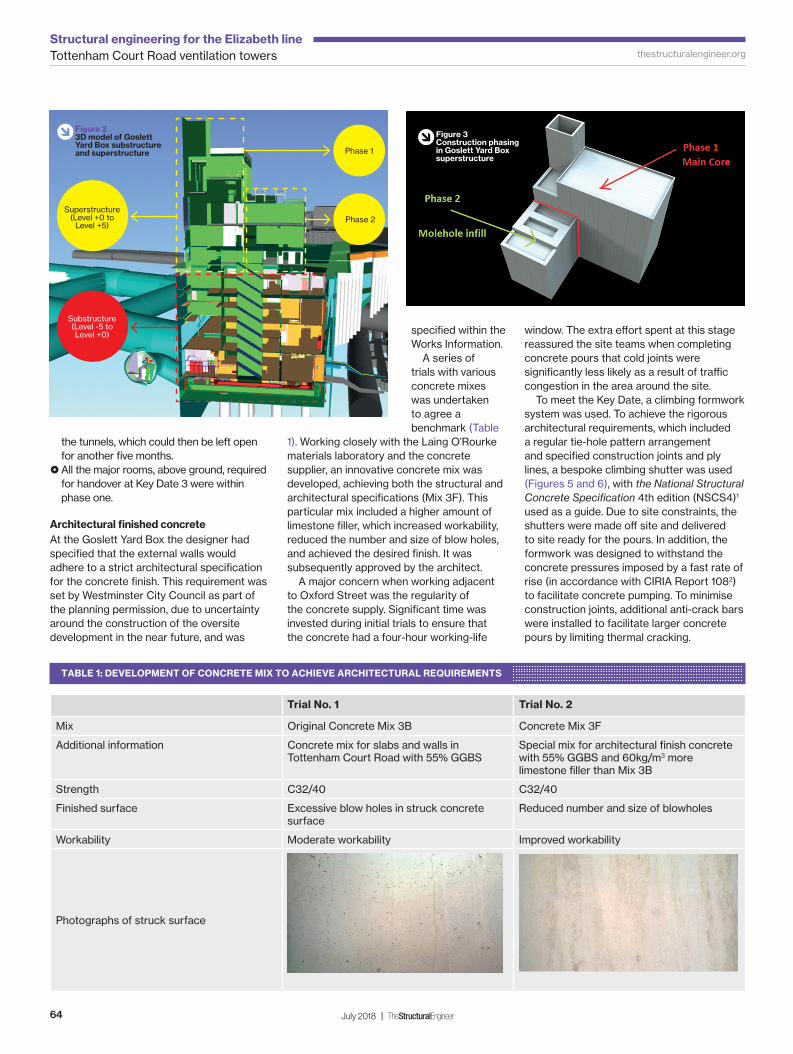
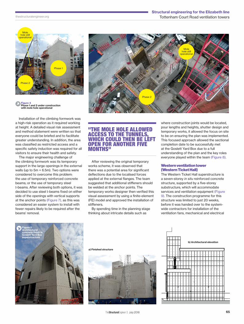
The construction of the superstructure was split into two phases (Figure 3). The major challenges in the construction of the Goslett Yard Box superstructure were the interface around other construction activities, architectural fi nished concrete and strict programme requirements.
Construction phasing
One of the main project milestones was the handover of rooms within the structure to the fi t-out contractor, known as Key Date 3. This served as a sectional completion for the project. Splitting the structure into two phases created two major benefi ts:
The mole hole (Figure 4) allowed access to
NOTATION
FE fi nite element
GGBS ground-granulated blast-furnace
slag
GYB Goslett Yard Box
WTH Western Ticket Hall
Western Ticket Hall
(WTH)Goslett
Yard Box(GYB)
� Figure 1General arrangement of Tottenham Court Road Elizabeth line station
TSE78_63-69_Tottenham CR Vents.indd 63TSE78_63-69_Tottenham CR Vents.indd 63 20/06/2018 17:5020/06/2018 17:50
Tottenham Court Road ventilation towersStructural engineering for the Elizabeth line
64 July 2018 | TheStructuralEngineer
thestructuralengineer.org
the tunnels, which could then be left open for another fi ve months. All the major rooms, above ground, required for handover at Key Date 3 were within phase one.
Architectural fi nished concrete
At the Goslett Yard Box the designer had specifi ed that the external walls would adhere to a strict architectural specifi cation for the concrete fi nish. This requirement was set by Westminster City Council as part of the planning permission, due to uncertainty around the construction of the oversite development in the near future, and was
specifi ed within the Works Information.
A series of trials with various concrete mixes was undertaken to agree a benchmark (Table
1). Working closely with the Laing O’Rourke materials laboratory and the concrete supplier, an innovative concrete mix was developed, achieving both the structural and architectural specifi cations (Mix 3F). This particular mix included a higher amount of limestone fi ller, which increased workability, reduced the number and size of blow holes, and achieved the desired fi nish. It was subsequently approved by the architect.
A major concern when working adjacent to Oxford Street was the regularity of the concrete supply. Signifi cant time was invested during initial trials to ensure that the concrete had a four-hour working-life
window. The extra eff ort spent at this stage reassured the site teams when completing concrete pours that cold joints were signifi cantly less likely as a result of traffi c congestion in the area around the site.
To meet the Key Date, a climbing formwork system was used. To achieve the rigorous architectural requirements, which included a regular tie-hole pattern arrangement and specifi ed construction joints and ply lines, a bespoke climbing shutter was used (Figures 5 and 6), with the National Structural
Concrete Specifi cation 4th edition (NSCS4)1
used as a guide. Due to site constraints, the shutters were made off site and delivered to site ready for the pours. In addition, the formwork was designed to withstand the concrete pressures imposed by a fast rate of rise (in accordance with CIRIA Report 1082) to facilitate concrete pumping. To minimise construction joints, additional anti-crack bars were installed to facilitate larger concrete pours by limiting thermal cracking.
Trial No. 1 Trial No. 2
Mix Original Concrete Mix 3B Concrete Mix 3F
Additional information Concrete mix for slabs and walls in Tottenham Court Road with 55% GGBS
Special mix for architectural fi nish concrete with 55% GGBS and 60kg/m3 more limestone fi ller than Mix 3B
Strength C32/40 C32/40
Finished surface Excessive blow holes in struck concrete surface
Reduced number and size of blowholes
Workability Moderate workability Improved workability
Photographs of struck surface
TABLE 1: DEVELOPMENT OF CONCRETE MIX TO ACHIEVE ARCHITECTURAL REQUIREMENTS
� Figure 23D model of Goslett Yard Box substructure and superstructure
� Figure 3Construction phasing in Goslett Yard Box superstructure
Superstructure(Level +0 to
Level +5)
Substructure(Level -5 to Level +0)
Phase 2
Phase 1
TSE78_63-69_Tottenham CR Vents.indd 64TSE78_63-69_Tottenham CR Vents.indd 64 20/06/2018 17:2520/06/2018 17:25
Tottenham Court Road ventilation towersStructural engineering for the Elizabeth line
65TheStructuralEngineer | July 2018
thestructuralengineer.org
Installation of the climbing formwork was a high-risk operation as it required working at height. A detailed visual risk assessment and method statement were written so that everyone could be briefed and to facilitate greater understanding. In addition, the area was classifi ed as restricted access and a specifi c safety induction was required for all visitors to ensure their health and safety.
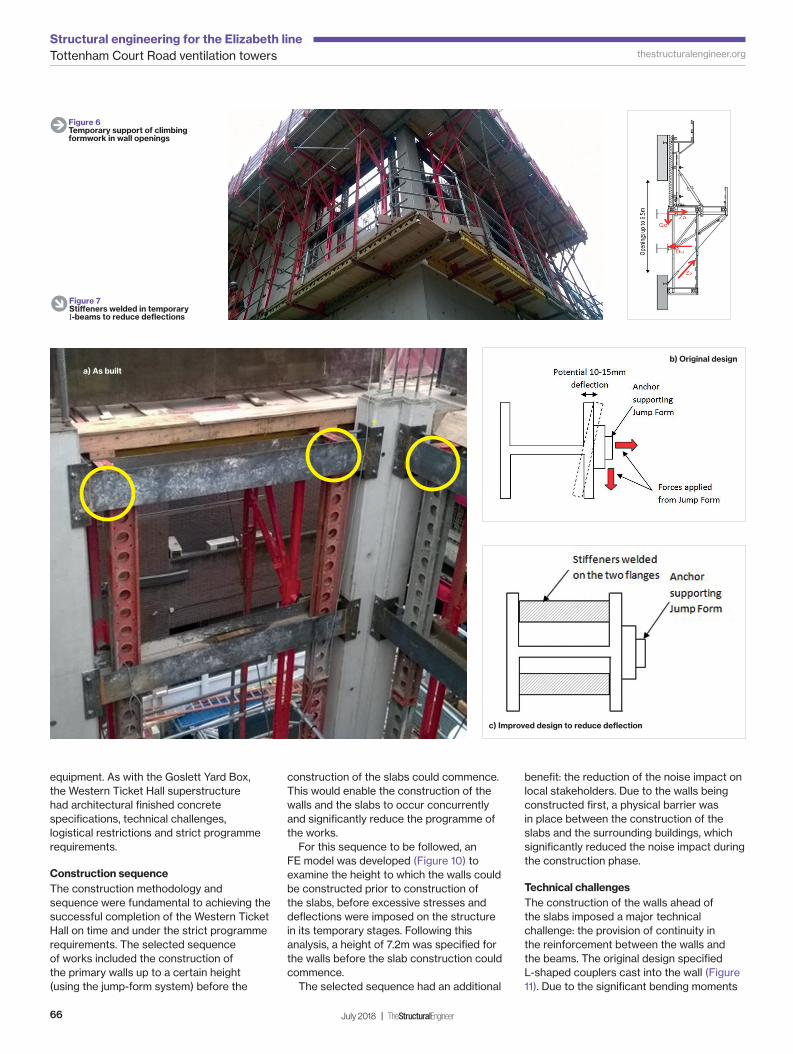
The major engineering challenge of the climbing formwork was its temporary support in the large openings in the external walls (up to 5m × 6.5m). Two options were considered to overcome this problem: the use of temporary reinforced concrete beams; or the use of temporary steel I-beams. After reviewing both options, it was decided to use steel I-beams fi xed on either side of the openings with vertical supports at the anchor points (Figure 7), as this was considered an easier system to install with fewer repairs likely to be required after the beams’ removal.
After reviewing the original temporary works scheme, it was observed that there was a potential area for signifi cant defl ections due to the localised forces applied at the external fl anges. The team suggested that additional stiff eners should be welded at the anchor points. The temporary works designer then verifi ed this visual assessment by using a fi nite-element (FE) model and approved the installation of stiff eners.
By spending time in the planning stage thinking about intricate details such as
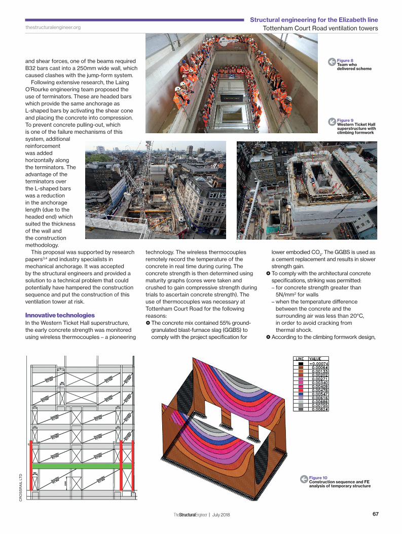
where construction joints would be located, pour lengths and heights, shutter design and temporary works, it allowed the focus on site to be on ensuring the plan was implemented. This focused approach allowed the sectional completion date to be successfully met at the Goslett Yard Box due to a full understanding of the plan and the key roles everyone played within the team (Figure 8).
Western ventilation tower (Western Ticket Hall)
The Western Ticket Hall superstructure is a seven-storey in situ reinforced concrete structure, supported by a fi ve-storey substructure, which will accommodate services and ventilation equipment (Figure 9). The construction programme for this structure was limited to just 20 weeks, before it was handed over to the system-wide contractors for installation of the ventilation fans, mechanical and electrical
� Figure 4Phase 1 and 2 under construction with mole hole operational
a) Finished structure
Phase 1
Phase 2
Mole hole still
operational
Phase 2
Mole hole still
operational
b) Architectural elevation
� Figure 5Architectural concrete fi nish in Goslett Yard Box superstructure
"THE MOLE HOLE ALLOWED ACCESS TO THE TUNNELS, WHICH COULD THEN BE LEFT OPEN FOR ANOTHER FIVE MONTHS"
TSE78_63-69_Tottenham CR Vents.indd 65TSE78_63-69_Tottenham CR Vents.indd 65 20/06/2018 17:5020/06/2018 17:50
Tottenham Court Road ventilation towersStructural engineering for the Elizabeth line
66 July 2018 | TheStructuralEngineer
thestructuralengineer.org
equipment. As with the Goslett Yard Box, the Western Ticket Hall superstructure had architectural fi nished concrete specifi cations, technical challenges, logistical restrictions and strict programme requirements.
Construction sequence
The construction methodology and sequence were fundamental to achieving the successful completion of the Western Ticket Hall on time and under the strict programme requirements. The selected sequence of works included the construction of the primary walls up to a certain height (using the jump-form system) before the
construction of the slabs could commence. This would enable the construction of the walls and the slabs to occur concurrently and signifi cantly reduce the programme of the works.
For this sequence to be followed, an FE model was developed (Figure 10) to examine the height to which the walls could be constructed prior to construction of the slabs, before excessive stresses and defl ections were imposed on the structure in its temporary stages. Following this analysis, a height of 7.2m was specifi ed for the walls before the slab construction could commence.
The selected sequence had an additional
benefi t: the reduction of the noise impact on local stakeholders. Due to the walls being constructed fi rst, a physical barrier was in place between the construction of the slabs and the surrounding buildings, which signifi cantly reduced the noise impact during the construction phase.
Technical challenges
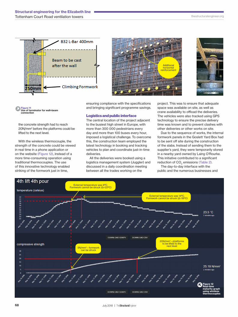
The construction of the walls ahead of the slabs imposed a major technical challenge: the provision of continuity in the reinforcement between the walls and the beams. The original design specifi ed L-shaped couplers cast into the wall (Figure 11). Due to the signifi cant bending moments
a) As built
b) Original design
c) Improved design to reduce defl ection
E Figure 6Temporary support of climbing formwork in wall openings
� Figure 7Stiff eners welded in temporary I-beams to reduce defl ections
TSE78_63-69_Tottenham CR Vents.indd 66TSE78_63-69_Tottenham CR Vents.indd 66 20/06/2018 17:5120/06/2018 17:51
Tottenham Court Road ventilation towersStructural engineering for the Elizabeth line
67TheStructuralEngineer | July 2018
thestructuralengineer.org
and shear forces, one of the beams required B32 bars cast into a 250mm wide wall, which caused clashes with the jump-form system.
Following extensive research, the Laing O’Rourke engineering team proposed the use of terminators. These are headed bars which provide the same anchorage as L-shaped bars by activating the shear cone and placing the concrete into compression. To prevent concrete pulling-out, which is one of the failure mechanisms of this system, additional reinforcement was added horizontally along the terminators. The advantage of the terminators over the L-shaped bars was a reduction in the anchorage length (due to the headed end) which suited the thickness of the wall and the construction methodology.
This proposal was supported by research papers3,4 and industry specialists in mechanical anchorage. It was accepted by the structural engineers and provided a solution to a technical problem that could potentially have hampered the construction sequence and put the construction of this ventilation tower at risk.
Innovative technologies
In the Western Ticket Hall superstructure, the early concrete strength was monitored using wireless thermocouples – a pioneering
technology. The wireless thermocouples remotely record the temperature of the concrete in real time during curing. The concrete strength is then determined using maturity graphs (cores were taken and crushed to gain compressive strength during trials to ascertain concrete strength). The use of thermocouples was necessary at Tottenham Court Road for the following reasons:
The concrete mix contained 55% ground-granulated blast-furnace slag (GGBS) to comply with the project specifi cation for
lower embodied CO2. The GGBS is used as a cement replacement and results in slower strength gain. To comply with the architectural concrete specifi cations, striking was permitted:– for concrete strength greater than
5N/mm2 for walls– when the temperature diff erence
between the concrete and the surrounding air was less than 20°C, in order to avoid cracking from thermal shock.
According to the climbing formwork design,
CR
OS
SR
AIL
LT
D
W Figure 8Team who delivered scheme
� Figure 9Western Ticket Hall superstructure with climbing formwork
W Figure 10Construction sequence and FE analysis of temporary structure
TSE78_63-69_Tottenham CR Vents.indd 67TSE78_63-69_Tottenham CR Vents.indd 67 20/06/2018 17:5220/06/2018 17:52
Tottenham Court Road ventilation towersStructural engineering for the Elizabeth line
68 July 2018 | TheStructuralEngineer
thestructuralengineer.org
the concrete strength had to reach 20N/mm2 before the platforms could be lifted to the next level.
With the wireless thermocouple, the strength of the concrete could be viewed in real time in a phone application or on the website (Figure 12), instead of a more time-consuming operation using traditional thermocouples. The use of this innovative technology enabled striking of the formwork just in time,
ensuring compliance with the specifi cations and bringing signifi cant programme savings.
Logistics and public interface
The central location of the project adjacent to the busiest high street in Europe, with more than 300 000 pedestrians every day and more than 100 buses every hour, imposed a logistical challenge. To overcome this, the construction team employed the latest technology in booking and tracking vehicles to plan and coordinate just-in-time deliveries.
All the deliveries were booked using a logistics management system (Juggler) and discussed in a daily coordination meeting between all the trades working on the
project. This was to ensure that adequate space was available on site, as well as crane availability to offl oad the deliveries. The vehicles were also tracked using GPS technology to ensure the precise delivery time was known and to prevent clashes with other deliveries or other works on site.
Due to the sequence of works, the internal formwork panels in the Goslett Yard Box had to be sent off site during the construction of the slabs. Instead of sending them to the supplier’s yard, they were temporarily stored in a nearby yard owned by Laing O’Rourke. This initiative contributed to a signifi cant reduction of CO2 emissions (Table 2).
The day-to-day interface with the public and the numerous businesses and
� Figure 11Use of terminator for wall–beam connection
� Figure 12Real-time maturity graph using wireless thermocouples
Additional horizontal
reinforcement
20N/mm2 – p\latforms to be lifted to the
next level5N/mm2 – formwork
can be struck
External temperature was 80C.Formwork cannot be struck (Δ=220C)
External temperature was 140C.Formwork cannot be struck (Δ=180C)
TSE78_63-69_Tottenham CR Vents.indd 68TSE78_63-69_Tottenham CR Vents.indd 68 20/06/2018 17:5220/06/2018 17:52
Tottenham Court Road ventilation towersStructural engineering for the Elizabeth line
69TheStructuralEngineer | July 2018
thestructuralengineer.org
stakeholders around Tottenham Court Road caused both logistical issues and operational challenges during the construction works. Generation of noise and vibration is an unavoidable outcome of the construction works for a complex infrastructure project. To minimise the impact on the local stakeholders, continuous liaison, early engagement and mutual understanding of each other’s needs was fundamental.
For example, adjacent to the Western Ticket Hall site there is a school and a recording studio which could potentially have been impacted by noise and vibration during exam periods and music recordings, respectively. The construction team and stakeholders worked closely together so that exam dates and recording sessions were embedded in the construction programme, ensuring that noise and vibration during those times were kept to a minimum. An example of this was all demolition work below ground ceasing during recording sessions, as the vibration generated by the activity interfered with the recording equipment.
Conclusions
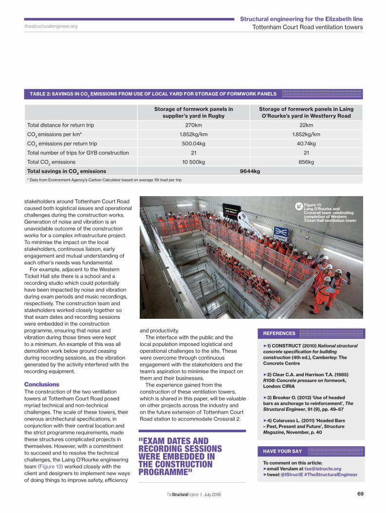
The construction of the two ventilation towers at Tottenham Court Road posed myriad technical and non-technical challenges. The scale of these towers, their onerous architectural specifi cations, in conjunction with their central location and the strict programme requirements, made these structures complicated projects in themselves. However, with a commitment to succeed and to resolve the technical challenges, the Laing O’Rourke engineering team (Figure 13) worked closely with the client and designers to implement new ways of doing things to improve safety, effi ciency
Storage of formwork panels in
supplier’s yard in Rugby
Storage of formwork panels in Laing
O’Rourke’s yard in Westferry Road
Total distance for return trip 270km 22km
CO2 emissions per km* 1.852kg/km 1.852kg/km
CO2 emissions per return trip 500.04kg 40.74kg
Total number of trips for GYB construction 21 21
Total CO2 emissions 10 500kg 856kg
Total savings in CO2 emissions 9644kg
* Data from Environment Agency’s Carbon Calculator based on average 15t load per trip
TABLE 2: SAVINGS IN CO2 EMISSIONS FROM USE OF LOCAL YARD FOR STORAGE OF FORMWORK PANELS
and productivity.The interface with the public and the
local population imposed logistical and operational challenges to the site. These were overcome through continuous engagement with the stakeholders and the team’s aspiration to minimise the impact on them and their businesses.
The experience gained from the construction of these ventilation towers, which is shared in this paper, will be valuable on other projects across the industry and on the future extension of Tottenham Court Road station to accommodate Crossrail 2.
"EXAM DATES AND RECORDING SESSIONS WERE EMBEDDED IN THE CONSTRUCTION PROGRAMME"
REFERENCES
E1) CONSTRUCT (2010) National structural
concrete specifi cation for building
construction (4th ed.), Camberley: The
Concrete Centre
E2) Clear C.A. and Harrison T.A. (1985)
R108: Concrete pressure on formwork,
London: CIRIA
E3) Brooker O. (2013) ‘Use of headed
bars as anchorage to reinforcement’, The
Structural Engineer, 91 (9), pp. 49–57
E4) Colarusso L. (2011) ‘Headed Bars
– Past, Present and Future’, Structure
Magazine, November, p. 40
HAVE YOUR SAY
To comment on this article:
Eemail Verulam at [email protected]
Etweet @IStructE #TheStructuralEngineer
� Figure 13Lang O’Rourke and Crossrail team celebrating completion of Western Ticket Hall ventilation tower
TSE78_63-69_Tottenham CR Vents.indd 69TSE78_63-69_Tottenham CR Vents.indd 69 20/06/2018 17:5220/06/2018 17:52