Embed Size (px)
Citation preview

Technical Report 4
Construction Methodology Report 29 March 2012
Technical Report 4 – Construction Methodology Report
// Page i
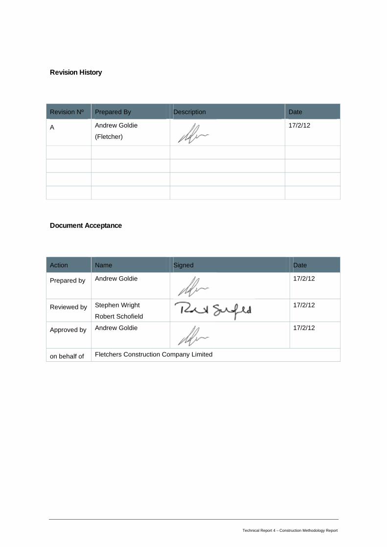
Revision History
Revision Nº Prepared By Description Date
A Andrew Goldie (Fletcher)
17/2/12
Document Acceptance
Action Name Signed Date
Prepared by Andrew Goldie
17/2/12
Reviewed by Stephen Wright Robert Schofield
17/2/12
Approved by Andrew Goldie
17/2/12
on behalf of Fletchers Construction Company Limited
Technical Report 4 – Construction Methodology Report // Page 2
Table of Contents
Overview ................................................................................................................... 3
1. Construction Philosophy ...................................................................................... 3
1.1. Construction Objectives ............................................................................................... 3
1.2. Programme and methodology ..................................................................................... 4
2. Sequence of Construction ................................................................................... 9
2.1. Stage 1......................................................................................................................... 9
2.2. Stage 2....................................................................................................................... 12
2.3. Stage 3....................................................................................................................... 17
2.4. Stage 4....................................................................................................................... 19
2.5. Stage 5....................................................................................................................... 21
2.6. Stage 6....................................................................................................................... 23
3. Project Establishment ....................................................................................... 24
3.1. Construction Yards .................................................................................................... 24
3.2. Water supply .............................................................................................................. 27
3.3. Construction Lighting ................................................................................................. 28
3.4. Construction Stormwater Drainage ........................................................................... 29
4. Summary of Environmental Effects .................................................................... 32
Technical Report 4 – Construction Methodology Report // Page 3
Overview
The purpose of this report is to outline the philosophies underlying the staging and sequencing
options selected for the Expressway construction. A general overview of the construction programme
and methods to be adopted is provided. The key features of operations in each specific section are
then outlined.
This report should be read in conjunction with the Erosion and Sediment Control Plan (ESCP –
Appendix H of the CEMP, Volume 4), which provides a detailed methodology for the environmentally
sensitive operations that this report outlines. Reference should also be made to the following drawing
sets:
Drawings CV-CM-100: Zone Diagram and Stages (Construction, Volume 5)
Drawings CV-CM-200: Erosion & Sediment Control (Management Plan Appendices, Appendix H,
Volume 5)
Drawings CV-CM-300: Construction Traffic Management & Access (Construction, Volume 5)
Drawings CV-CM-400: Construction Office & Yard Areas (Construction, Volume 5)
Drawings CV-CM-500: Waikanae River Bridge & Streamworks (Management Plan Appendices,
Appendix H, Volume 5)
1. Construction Philosophy
1.1. Construction Objectives
The objective of the construction phase is to deliver a high quality product, in the most cost-effective
and efficient manner, with zero harm to those involved, whilst minimising the effects on the
surrounding environment and the local community.
To achieve this objective, the construction methodology has the following key features:
• Preloading of the large peat deposits at north and south ends to minimise waste material
removed from site.
• Progression of the central section of proposed Expressway during preload settlement period.
• Use of the proposed Expressway route and bridges to transport materials, thereby
maintaining east-west connectivity and minimising construction traffic on local roads.
Technical Report 4 – Construction Methodology Report // Page 4
• Sequencing of construction to achieve cut to fill balance of earthworks and reuse of preload
surcharge material, in order to minimise the requirement for imported aggregate from local
quarry sources and waste material removed from site.
• Selection of aggregate sources to minimise disruption of quarry traffic on local roads.
• Traffic management arrangements that are cognisant of all road users, including pedestrians,
cyclists and horse-riders.
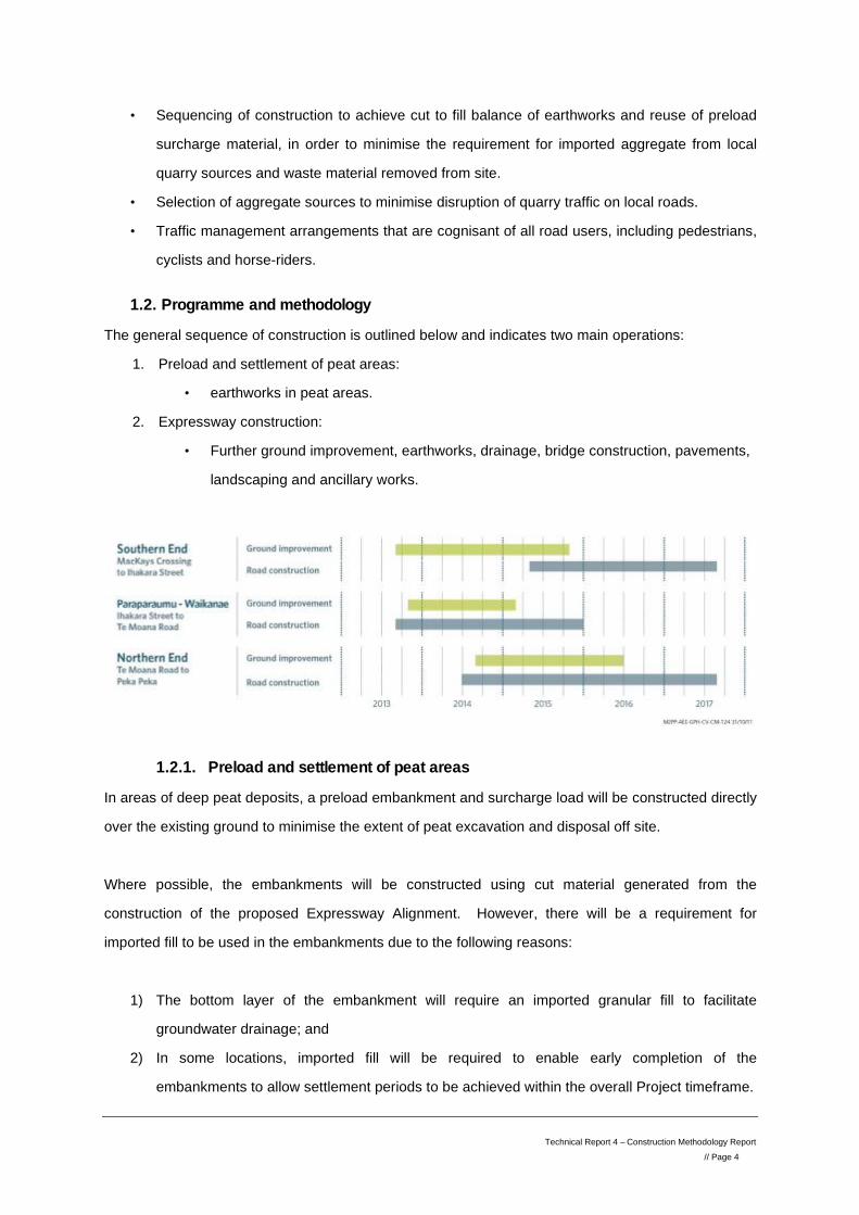
1.2. Programme and methodology
The general sequence of construction is outlined below and indicates two main operations:
1. Preload and settlement of peat areas:
• earthworks in peat areas.
2. Expressway construction:
• Further ground improvement, earthworks, drainage, bridge construction, pavements,
landscaping and ancillary works.
1.2.1. Preload and settlement of peat areas
In areas of deep peat deposits, a preload embankment and surcharge load will be constructed directly
over the existing ground to minimise the extent of peat excavation and disposal off site.
Where possible, the embankments will be constructed using cut material generated from the
construction of the proposed Expressway Alignment. However, there will be a requirement for
imported fill to be used in the embankments due to the following reasons:
1) The bottom layer of the embankment will require an imported granular fill to facilitate
groundwater drainage; and
2) In some locations, imported fill will be required to enable early completion of the
embankments to allow settlement periods to be achieved within the overall Project timeframe.
Technical Report 4 – Construction Methodology Report // Page 5
Potential sources of fill for the preload embankments include:
• Kāpiti Quarry, Paraparumu; and
• Ōtaki Quarry.
The sourcing of material from each of these quarries will be carefully managed during construction to
minimise both haul distances to each embankment and truck movements from each quarry.
Placement of the embankment fill material will work progressively from the nearest hardstand area,
either a haul road or local road. Where possible, the permanent stormwater drainage, including
wetland and flood offset storage areas will be formed and installed ahead to enable the drainage
features to be used for erosion and sediment control. The ESCP details the construction
methodology to be adopted for the preload embankments, including the provision of temporary
drainage and use of permanent drainage as sediment control devices.
The preload settlement periods for each embankment vary in duration from 6 months to 18 months.
During these settlement periods, work on the proposed Expressway will continue in other areas.
1.2.2. Expressway construction
During the preload construction and settlement periods at the north and south ends, completion of the
proposed Expressway and cycleway/walkway will proceed on two fronts working simultaneously away
from the central Otaihanga Project Yard: north towards Peka Peka Road and south to Raumati Road
(refer to drawing CV-CM-406, Construction, Office and Yard Plans, Volume 5).
The Otaihanga Project Yard will therefore be the central hub for all construction work. In order to
manage the increase in traffic anticipated on Otaihanga Road, the existing intersection with SH1 will
be upgraded to a roundabout configuration.
Each section, including the bridge across the road or waterway to the next section will be constructed
consecutively and progressively away from Otaihanga. As each bridge and section is completed, it
will provide a passage through to the next section. Materials can then be moved through the site,
using the proposed Expressway corridor from Otaihanga Road as a haul route.
This methodology will minimise both the volume of construction traffic on local roads and the
disturbed land area within the Designation. However, in order to achieve this objective, the bridge
construction and associated groundworks will need to be accessed from the local roads.
Technical Report 4 – Construction Methodology Report // Page 6
The major on-road and off-road haulage routes, including the haulage for the preload embankment fill
material, are illustrated in drawing CV-CM-108, Construction, Zone Diagram and Stages, Volume 5.
1.2.3. Earthworks
Each section will be progressed as an individual work package. Following clearance of the site,
services will be diverted where required and erosion and sediment control devices will be installed
(refer to ESCP). Earthworks will be then be carried out, with drainage items being progressively
completed to enable operations to advance. Wetland and flood offset storage areas will also be
formed at this time and used for sediment control. Bridge construction works, at the ends of each
section, will also be completed during the earthworks activities. Upon completion of cut to fill activities
within the section, any further earth-moving required between sections will be carried out after
completion of the bridge structure. Off-road dump trucks will utilise the completed proposed
Expressway corridor and bridges as a haul route.
Where peat is encountered in locations outside of the preload areas, it will be removed and replaced
with sand fill. Peat will also be removed in the formation of wetlands and flood water storage areas.
The detailed methodology for these operations is outlined in the ESCP.
Initially, the peat will be stockpiled adjacent to the site and allowed to dry sufficiently to reduce
haulage around and off the site. The peat material will be used as far as possible in landscaping and
the formation of acoustic barriers to minimise disposal off site. Any excess peat will then be removed
from the site, via the proposed Expressway corridor haul route, to consented dump sites. Possible
sites could include:
1. Bright’s Cleanfill, Kāpiti Quarry, Paraparaumu, via on-road haul route exiting from Poplar
Avenue;
2. Waikanae Oxidation Ponds, Paetawa Road to assist in the rehabilitation of this area into a
recreational reserve (refer to the Ecological Management Plan - Appendix M of the CEMP,
Volume 4), via an on-road haul route exiting from Te Moana Road; and
3. Otaihanga Landfill, via an off-road haul route exiting direct from the proposed Expressway
corridor.

Technical Report 4 – Construction Methodology Report // Page 7
1.2.4. Bridge Construction
Each bridge, whether a road crossing or stream/river crossing, will be constructed in the following
sequence:
1) Preparation for ground improvements:
a. Cut existing ground to level of base of abutment, where required. Temporary retaining
walls may be required to support adjacent property or infrastructure.
b. Replace peat with sand fill, where required. Temporary retaining walls and dewatering
may be required to facilitate this operation.
2) Install stone columns, using vibroreplacement techniques. Extensive water jetting is
anticipated with this operation. The ESCP details how sediment will be controlled from this
operation.
3) Install piles, using the following techniques:
a. Bored piles;
b. Driven steel ‘H’ piles;
c. Bottom driven steel casing with reinforced concrete; and
d. Continuous flight auger (CFA).
4) Construct pile cap where required. Where high water table is experienced, sheet piles will be
installed around the pile cap construction area and the area dewatered.
5) Construct concrete column and crossheads and construct Mechanically Stabilised Earth
(MSE) wall abutment.
6) Place prefabricated deck units by crane. Where the bridge crosses a live road, this operation
will be carried out within a night-time road closure. Bridge deck beam units will be
prefabricated in the Otaihanga Yard and transported by road to each site.
7) Complete top deck and side barriers.
Concrete supply will be from a supplier local to Kāpiti Coast. Concrete deliveries will be to either the
Otaihanga Yard for prefabrication activities or to the individual bridge sites. All sites will be accessed
via SH1 and local roads.
Technical Report 4 – Construction Methodology Report // Page 8
Road bridges will have differing environmental controls to stream/river crossings and both are detailed
in the ESCP (Appendix H of the CEMP, Volume 4). The Construction Traffic Management Plan
(Appendix O of the CEMP, Volume 4) details the proposals to control vehicular, pedestrian, cyclist
and equestrian traffic during road crossings.
1.2.5. Pavement construction
Upon completion of the earthworks, drainage and bridges in each Section, pavement materials will be
laid. One carriageway of the proposed Expressway will be completed and sealed to enable
immediate protection of the subgrade and pavement layers and allow a progressive completion of the
proposed Expressway. The other carriageway will be completed to subbase level, to protect the
subgrade and create the proposed Expressway corridor haul route for the bulk earthmoving activity
and other construction traffic.
Upon completion of the required settlement periods for the preload areas, construction of the
proposed Expressway in these areas will proceed. The preload surcharge will be removed and used
as fill elsewhere along the proposed Expressway corridor, thus minimising the overall use of imported
fill on the proposed Expressway. Pavement materials can then be placed on the remaining
embankment to complete the road structure.
As the main carriageway is completed in each Section, the cycleway/walkway will also be completed.
Once all works are complete on each carriageway section, traffic services, roadside furniture and
landscaping, including acoustic barriers will proceed.
1.2.6. Construction Zones and Sections
For the purposes of programming and for effectively managing the physical works, the length of the
proposed Expressway will be split into two Construction Zones: North & South and 16 Sections:
SOUTH ZONE
POP: Poplar Avenue Interchange (and south tie-in to existing SH1)
POP-RAU: Poplar Avenue – Raumati Road
RAU-IHA: Raumati Road – Ihakara Street/Wharemauku Stream
IHA-KAP: Ihakara Street/Wharemauku Stream – Kāpiti Road
KAP: Kāpiti Road Interchange
KAP-MAZ: Kāpiti Road – Mazengarb Road
Technical Report 4 – Construction Methodology Report // Page 9
MAZ-OT: Mazengarb Road – Otaihanga Road
NORTH ZONE
OT-WAI: Otaihanga Road – Waikanae River
WAI-TEM: Waikanae River – Te Moana Road
TEM: Te Moana Road Interchange
TEM-NGA: Te Moana Road - Ngarara Road
NGA: Ngarara Road Area
SMI: Smithfield Road Area
SMI-15400: Smithfield Road Area – CH.15400
15400-PP: CH.15400 – Peka Peka Interchange
PP: Peka Peka Interchange (and north tie-in to existing SH1)
These Zones and Sections are outlined in drawing CV-CM-101, Construction, Zone Diagram and
Stages, Volume 5.
2. Sequence of Construction
Reference should be made to Drawings CV-CM-102-107, Construction, Zone Diagram and Stages,
Volume 5 while reading the following construction sequence.
2.1. Stage 1
(Drawing CV-CM-102, Construction, Zone Diagram and Stages, Volume 5)
2.1.1. IHA-KAP: Preload
The preload fill embankments in the IHA-KAP section will be constructed using a
combination of imported fill and on-site cut to fill material to minimise on-road haulage and
use of local quarry resources. Imported fill material will be delivered from Kāpiti Quarry,
Paraparaumu, accessing from Kāpiti Road.
2.1.2. RAU-IHA: Preload
The preload fill embankments in the RAU-IHA section will be constructed using a combination of
imported fill and cut to fill material from within the section to minimise on-road haulage. Imported fill
material will be delivered from Kāpiti Quarry, Paraparaumu via Ihakara Street. A temporary haul road
will be constructed between the end of Ihakara Street and the proposed Expressway Alignment to
facilitate material movements to and from the works in this location.
Technical Report 4 – Construction Methodology Report // Page 10
2.1.3. MAZ-OT: Preload
Following completion of the IHA-KAP preload embankment, the preload embankment in the MAZ-OT
Section will be constructed. Imported fill material will be delivered from Kāpiti Quarry, accessing via
the Otaihanga Yard, off Otaihanga Road. Cut to fill material from TEM-NGA will also be used. This
material will be transported off-road via the proposed Expressway route, following completion of the
Otaihanga Road Bridge, Waikanae River Road Bridge, Te Moana Road Bridge and haul route
through this area.
2.1.4. 15400-PP: Preload
The preload embankment from chainage15400 to the Peka Peka Interchange will be constructed in
two parts:
1. Placing imported fill from Ōtaki Quarry to form the lower embankment layer. This will provide
a haul route to works in the Smithfield Road area (SMI).
2. Completion of the preload embankment through to 17700 using cut to fill material from TEM-
NGA, following completion of the works in SMI (refer to 2.2.6).
Access for the preload embankment will be via Peka Peka Road (drawing CV-CM-324, Construction,
Traffic Management, Volume 5). At this stage, the Peka Peka Interchange construction yard will be
established as shown in drawing CV-CM-411, Construction, Office and Yard Plans, Volume 5.
In order to transport fill material across the Paetawa Stream and other waterways, all stream
crossings will be constructed early in this stage. Materials, including any structural bridge units will be
transported to site via SH1 and Peka Peka Road and using the preload embankment under
construction as a haul route.
2.1.5. SMI-15400: Expressway Construction
Completion of the SMI-15400 Section is critical to the programme in order to create a haul route to
transport cut to fill material from the TEM-NGA section to Peka Peka Interchange and also facilitate
early access to the Smithfield Road area.
The formation of the proposed Expressway will be carried out using cut to fill and peat replacement
operations, completing drainage works as the earthworks progresses. Any additional fill required in
this area will be transported off-road from the TEM-NGA and NGA sections, crossing Ngarara Road if
necessary as detailed in drawing CV-CM-322, Construction, Traffic Management, Volume 5. This will
occur following completion of the works in the Smithfield Road area (refer to 2.2.6).
Technical Report 4 – Construction Methodology Report // Page 11
Upon completion of the earthworks and drainage activity, the proposed Expressway pavement will be
completed, with materials being brought to site along the initial preload embankment layers from Peka
Peka Road. One carriageway will be completed to subbase level at first to provide a haul route
between the TEM-NGA section and the Peka Peka Interchange. The other carriageway will be
completed to seal to enable immediate protection of the subgrade and pavement layers and allow a
completion of this section of the proposed Expressway. Following completion of all earthworks for the
Peka Peka Interchange, the haul route will be paved and surfaced.
2.1.6. OT-WAI : Expressway Construction
The construction yard for the Otaihanga Road works will be arranged as shown in drawing CV-CM-
406, Construction, Office and Yard Plans, Volume 5. Work on this section will begin following
establishment of the Project facilities on Otaihanga Road, including construction of Otaihanga Road
Roundabout, and after any archaeological investigations.
During the construction of the preload embankments at RAU-IHA and MAZ-OT, the OT-WAI section,
including Otaihanga Road Bridge will proceed. Completion of Otaihanga Road Bridge as one of the
first activities in the programme will enable the early development of main construction access route
onto the Alignment from Otaihanga Road, through the Otaihanga Yard (drawing CV-CM-314,
Construction, Traffic Management, Volume 5).
Prior to the construction of the OT-WAI section, the current private access road to Otaihanga Nurseries and other properties will be realigned to its new route. Temporary traffic control will be used to complete the tie-in with Otaihanga Road and with the existing accessway Alignment (drawing CV-CM-316, Construction, Traffic Management, Volume 5). With local traffic using this new link, construction of the proposed Expressway can proceed.
Construction of the bridge over Otaihanga Road will include excavation of the existing ground to the
level of the abutment base. Due to the traffic volumes on Otaihanga Road, bridge beam placement
will proceed under night-time road closures (drawing CV-CM-315, Construction, Traffic Management,
Volume 5). All material deliveries to the bridge site, including aggregate for the stone columns and
MSE walls will be delivered via Otaihanga Road.
The earthworks phase of this section will involve moving material along the Alignment between
Otaihanga Road and Waikanae River. Any excess cut to fill material will be moved to the WAI-TEM
section, following completion of the Waikanae River Bridge. Upon completion of the earthworks
Technical Report 4 – Construction Methodology Report // Page 12
activity and installation of the stormwater drainage systems, the proposed Expressway pavement will
be completed. Road materials will be delivered from both Kāpiti Quarry and Ōtaki Quarry, accessing
across Otaihanga Road Bridge from the Otaihanga Yard.
2.2. Stage 2
(Drawing CV-CM-103, Construction, Zone Diagram and Stages, Volume 5)
2.2.1. MAZ-OT: Road realignment and bridge construction
During the preload settlement period in the MAZ-OT Section, the realignment of Mazengarb Road and
groundworks for the bridge will proceed as follows and as shown in drawing CV-CM-311 & 312
(Construction, Traffic Management, Volume 5):
1. With the north side of Mazengarb Road closed and traffic moved south, install piles to
Retaining Wall A.
2. Excavate against the west end of Retaining Wall A and down to the new road level.
3. Cut material will be used as fill against the east end of the Retaining Wall A and to level out
the area for the Mazengarb Road Bridge north abutment.
4. Install stone columns.
5. Complete lower pavement layers to north side.
6. Move traffic to north side and close south side of Mazengarb Road.
7. Install piles to Retaining Wall B.
8. Excavate against the wall and down to the new road level. Excavate for south abutment
ground improvements.
9. Install stone columns.
10. Complete new road surface, while bridge construction proceeds.
Bridge beams will be cast off-site in Otaihanga Yard and then transported to site and placed in
position. Due to the traffic volumes on Mazengarb Road, bridge beam placement will proceed under
night-time road closures (drawing CV-CM-313, Construction, Traffic Management, Volume 5). All
material deliveries to the bridge site, including concrete, aggregate for the stone columns and MSE
walls will be delivered via Mazengarb Road.
The proposed site layout for the Mazengarb Road Bridge construction is shown in drawing CV-CM-
405, Construction, Office and Yard Plans, Volume 5.
Technical Report 4 – Construction Methodology Report // Page 13
2.2.2. WAI-TEM: Expressway Construction
Following completion of the earthworks in OT-WAI and along with any necessary archaeological
investigations, work will commence in the WAI-TEM section, including construction of the Waikanae
River Bridge and associated river reprofiling works. The construction yard areas for the Waikanae
River Bridge and streamworks will be arranged as shown in drawing CV-CM-407, Construction, Office
and Yard Plans, Volume 5. These areas have been selected to ensure the yards remain outside of
the river floodplain.
Waikanae River Bridge The staging of construction and environmental protection measures for the Waikanae River Bridge
will be as follows and as detailed in drawings CV-CM-500-508, Management Plan Appendices,
Appendix H, Volume 5.
1) Establish southern site and install temporary works:
a. Install flood plain scour protection and use as access to worksite;
b. Create temporary diversion of Muaupoko Stream; and
c. Install temporary fencing and protection to adjacent properties and to public.
2) Excavate ground to base of south abutment and complete stone column installation.
3) Complete piling to south bank piers.
4) Complete piling to southern abutment. Form pile cap to south bank pier piles.
5) Construct columns and crossheads on south bank.
6) Complete south bank streamworks. Construct columns and crossheads to southern
abutment and build up MSE abutment walls.
7) Construct southern settlement slab and install south deck units.
8) Install flood plain scour protection to the north and use as access to worksite. Repeat (2)-(6)
for north side. Complete footpath realignment and El Rancho access.
9) Install remaining bridge deck units and complete topping slab and barriers.
Further details of this methodology and the particular environmental controls to be used can be found
in the ESCP. Where practicable, groundworks and streamworks will be programmed between
November and April, when stream flows are at their lowest and works can progress outside of fish
spawning and migration periods.
Access for construction vehicles and material deliveries to the south side of the river will be from
Otaihanga Road via the Otaihanga Yard and OT-WAI section. The north side will be accessed from
Technical Report 4 – Construction Methodology Report // Page 14
Te Moana Road, via the TEM section (drawing CV-CM-316, Construction, Traffic Management,
Volume 5). The existing public access into El Rancho will be maintained while the bridge works and
new accessway Alignment are constructed. Upon completion of the new accessway, the old access
road will be closed to enable completion of the north approach ramp.
At various stages during the construction works on each bank of the Waikanae River, the footpath will
need to be closed. Where possible, the existing tracks will be diverted around construction works
(refer to drawings CV-CM-500-508, Management Plan Appendices, Appendix H, Volume 5). Where it
is not practicable or safe to create routes around the worksite, users will be diverted across to the
opposite bank from the construction works via the existing footbridges to the east and west of the
Designation. Public notices will be provided ahead of each stage of construction to advise users of
planned footpath routes.
Earthworks and Pavements The earthworks phase of this section will involve moving material along the Alignment between
Waikanae River and Te Moana Road. Any shortfall in fill material to complete the earthworks will be
provided from the OT-WAI section, using the Waikanae River Bridge once complete.
Upon completion of the earthworks activity, the proposed Expressway pavement will be completed.
Road materials will be delivered from both Kāpiti Quarry and Ōtaki Quarry, accessing via Otaihanga
Road Bridge and the completed Waikanae Bridge from the Otaihanga Yard.
2.2.3. TEM – Expressway Construction
Following completion of the earthworks in WAI-TEM, the reconfiguration of Te Moana Road and
construction of the Te Moana Road Interchange (TEM) will commence. The construction yard for Te
Moana Intersection will be arranged as shown in drawing CV-CM-408, Construction, Office and Yard
Plans, Volume 5.
Additional fill material will be required to complete the earthworks in this section. Therefore, the main
cut to fill section, TEM-NGA, will also commence at this stage.
Drawings CV-CM-317 to 319, Construction, Traffic Management, Volume 5 show the traffic
management arrangements and staging for reconfiguring Te Moana Road:
1) With the existing Te Moana Road lanes narrowed and moved north, the south side of the
new roundabouts will be formed.
Technical Report 4 – Construction Methodology Report // Page 15
2) Traffic will then be diverted around this new formation to enable the completion of the north
side.
3) Traffic will be diverted around the outsides of the roundabouts to complete construction
Three bridges require construction at Te Moana Road:
1. Expressway over Te Moana Road
2. Northbound On-Ramp over Waimeha Stream
3. Southbound Off-Ramp over Waimeha Stream
Construction will involve peat replacement to the ground improvements area at each bridge and
temporary diversion of the Waimeha Stream, prior to commencement of stone column installation.
Due to the traffic volumes on Te Moana Road, bridge beam placement will proceed under night-time
closures with traffic using the southern on- and off-ramps as a detour route, as shown in drawing CV-
CM-320, Construction, Traffic Management, Volume 5. All material deliveries to the bridge site,
including aggregate for the stone columns and MSE walls will be delivered via Te Moana Road.
The earthworks phase of this section will involve moving material along the Alignment between
Waikanae River and Te Moana Road and from the cut to fill section TEM-NGA. Any shortfall in fill
material to complete the earthworks to the south embankment will be provided from the TEM-NGA
section, crossing Te Moana Road. Where practicable, this operation will be staged to follow
completion of the bridge to minimise disruption to traffic on Te Moana Road.
Upon completion of the earthworks activity, the proposed Expressway pavement will be completed.
Road materials will be delivered from both Kāpiti Quarry and Ōtaki Quarry, accessing via Otaihanga
Road Bridge and the completed Waikanae Bridge and Te Moana Bridge from the Otaihanga Yard.
2.2.4. SMI – Expressway Construction
The SMI section consists of the following stages:
1) Realignment of Smithfield Road, including construction of 2 bridges: a. Smithfield Road Bridge (over Expressway); b. Kakariki Bridge 1 (Smithfield Road over Kakariki Stream).
2) Stream realignment and wetlands/flood offset storage construction. 3) Construction of the proposed Expressway, including construction of the Kakariki Bridge 2
(Expressway over stream).
Technical Report 4 – Construction Methodology Report // Page 16
The construction yard areas and accesses for SMI will be arranged as shown in Drawing CV-CM-410,
Construction, Office and Yard Plans, Volume 5.
1) Realignment of Smithfield Road The formation of the new Smithfield Road alignment will be carried out using earthworks and road construction machinery, accessing along the preload embankment from Peka Peka Road (refer to 2.1.4) and Smithfield Road. Fill material for the earthworks will be available within the site. Construction of this new road and the diversion of traffic onto it will need to occur prior to commencement of the stream diversion work and proposed Expressway construction in this section.
Kakariki Bridge 1 will be completed first to enable a route for material deliveries across the Kakariki
Stream and further along the new Smithfield Road towards the site of Smithfield Road Bridge. All
material deliveries to the bridge sites, including aggregate for the stone columns, structural units and
MSE walls will be delivered via the preload embankment from Peka Peka Road and Smithfield Road.
During the installation of the stone columns and bridge construction activities, the Kakariki Stream will
be diverted around the work area. Access to Nga Manu will be maintained.
Construction will then proceed up to the Smithfield Road Bridge site and further on to complete the
tie-in with Ngarara Road (refer to drawing CV-CM-323, Construction, Traffic Management, Volume 5).
Access and material deliveries will remain via Peka Peka Road, the preload embankment to
Smithfield Road and the newly constructed Smithfield Road.
2) Stream realignment and wetlands Upon completion and opening of the new Smithfield Road to traffic, the old road and existing Nga
Manu access will be closed. This will enable construction of the stream diversions and wetlands in
the SMI area to be completed. The redundant roads will be used as haul routes around the SMI area.
Further methodologies for these streamworks can be found in the ESCP.
3) Construction of expressway
Following completion of the streamworks, the construction of the proposed Expressway in the SMI
Section will commence.
The ground improvements and bridge construction for Kakariki Bridge 2 will proceed adjacent to the
existing Kakariki Stream (refer to drawing CV-CM-410, Construction, Office and Yard Plans, Volume
5). If necessary, the stream will be diverted around the worksite. During the bridge construction, the
new channel for the stream will be formed. Diversion of the stream to the new alignment will occur
Technical Report 4 – Construction Methodology Report // Page 17
following completion of the bridge construction. Further methodologies for these streamworks can be
found in the ESCP.
The earthworks will involve moving material along the Alignment within the section to construct the
road formation. Any additional fill required in this area will be transported from the TEM-NGA and
NGA sections, crossing Ngarara Road as necessary, as detailed in drawing CV-CM-322,
Construction, Traffic Management, Volume 5.
Upon completion of all earthworks activity, the proposed Expressway pavement will be constructed.
Road materials will be delivered from both Kāpiti Quarry and Ōtaki Quarry, accessing via the
Otaihanga Yard and Peka Peka Road.
2.3. Stage 3
(Drawing CV-CM-104, Construction, Zone Diagram and Stages, Volume 5)
2.3.1. POP : Preload
Following clearance of the site, relocation of any services and installation of the designed drainage
systems and erosion and sediment control measures (see Appendix H of the CEMP, Volume 4), the
preload embankment will be formed in the POP section. The construction yard for Poplar Avenue
Intersection will be arranged as shown in Drawing CV-CM-401, Construction, Office and Yard Plans,
Volume 5.
A combination of imported fill and cut to fill material from the TEM-NGA section will be used for the
embankment, accessing the site at Poplar Avenue as shown in Drawing CV-CM-301, Construction,
Traffic Management, Volume 5. The cut to fill material will be transported by road trucks, exiting the
site at the Otaihanga Yard and using SH1 to deliver the material to Poplar Avenue.
2.3.2. POP-RAU: Preload
For the preload embankment in the POP-RAU Section, a combination of imported fill and cut to fill
material from the TEM-NGA section will be used. At this stage, the cul-de-sac end to Leinster Avenue
will be formed to enable construction to proceed. Fill material will be delivered to an access on SH1
at the old Leinster Avenue intersection.
2.3.3. 15400-PP: Preload
The preload embankment in this section will have started during Stage 1 (refer to 2.1.4). To complete
the embankment, cut to fill material from the TEM-NGA and NGA sections will be used to minimise

Technical Report 4 – Construction Methodology Report // Page 18
on-road haulage of fill materials. Off-road dump trucks will cart fill material along the proposed
Expressway corridor, through the SMI and SMI-15400 Sections.
2.3.4. MAZ-OT: Expressway Construction
Upon completion of the preload settlement in the MAZ-OT section, the earthworks, drainage and
pavement work will be completed. Materials, including the preload surcharge material, will be moved
along the proposed Expressway corridor between Otaihanga Road and Mazengarb Road. Any
excess material will be used as fill material in the sections to the south, transported off-road upon
completion of the bridges.
When all earthworks activity is complete, the proposed Expressway pavement will be constructed.
Road materials will be delivered from both Kāpiti Quarry and Ōtaki Quarry, accessing via the
Otaihanga Yard.
2.3.5. KAP-MAZ: Expressway Construction
Following completion of the earthworks in the MAZ-OT Section, earthworks and drainage work will
commence in the KAP-MAZ Section. To reduce the risk of sand being blown into neighbouring
residential areas during construction of this section, the earthworks will be programmed to take place
outside of the Spring equinox period, when prevailing winds can be at their strongest. In addition, as
detailed in the ESCP, particular attention will be given to dust suppression in this residential section.
Fill material will be moved along the proposed Expressway corridor between Mazengarb Road and
the north end of the Kāpiti Road Interchange (KAP). Upon completion of all earthworks activity, the
proposed Expressway pavement will be completed. Road materials will be delivered from both Kāpiti
Quarry and Ōtaki Quarry, accessing via the completed Mazengarb Road Bridge from the Otaihanga
Yard.
2.3.6. KAP: Expressway Construction
Construction works in the KAP Section consist of modifying the existing Kāpiti Road to configure the
new intersection layout, construction of the bridge across Kāpiti Road and formation of the on- and
off-ramps. The layout of the site during these works is shown in drawing CV-CM-404, Construction,
Office and Yard Plans, Volume 5.
Technical Report 4 – Construction Methodology Report // Page 19
Prior to works commencing on the proposed Expressway in the KAP section, the widening of Kāpiti
Road will be completed as shown in drawings CV-CM-308 & 309, Construction, Traffic Management,
Volume 5:
1) Complete the southern widening, including any service diversions;
2) Divert traffic onto the southern widening; and
3) Complete works to northern side, including service diversions and construction of bridge pier.
Construction of the bridge at Kāpiti Road will involve excavation of the existing ground to the
abutment base level to enable stone column construction to proceed. All material deliveries to the
bridge site, including aggregate for the stone columns and MSE walls will be delivered via Kāpiti
Road. Bridge beam placement should be able to proceed during the day by diverting traffic around
the placement operations using the widened intersection footprint. However, should any works
require closure of Kāpiti Road, they will be carried out under night-time closures with traffic diverted
as shown in drawing CV-CM-310, Construction, Traffic Management, Volume 5.
The earthworks phase for the intersection will involve moving material south along the Alignment from
KAP-MAZ and north along the Alignment from IHA-KAP. In this way, the use of Kāpiti Road to
transport materials will be minimised. Upon completion of the earthworks activity and installation of
the drainage systems, the proposed Expressway pavement will be completed. Road materials will be
delivered from both Kāpiti Quarry and Ōtaki Quarry, accessing from the Otaihanga Yard.
2.3.7. IHA-KAP: Expressway Construction
Following the preload settlement period in the IHA-KAP Section, the surcharge material will be
removed and used for peat replacement activities within the section and for completing the bridge
embankments at either end.
Upon completion of the earthworks and of Kāpiti Road Bridge, the proposed Expressway pavement
will be undertaken. Materials will be delivered from both Kāpiti Quarry and Ōtaki Quarry, accessing
from the Otaihanga Yard.
2.4. Stage 4
(Drawing CV-CM-105, Construction, Zone Diagram and Stages, Volume 5)
Technical Report 4 – Construction Methodology Report // Page 20
2.4.1. NGA: Expressway Construction
To commence initial cut to fill operations in the NGA section, a temporary crossing of Ngarara Road
will be established to enable fill material to be transported north (drawing CV-CM-321, Construction,
Traffic Management, Volume 5).
Following formation of the proposed Expressway route north of Ngarara Road and to enable the cut to
fill operations and construction of the Ngarara Road Bridge to continue, traffic will be diverted via a
temporary road, crossing the proposed Expressway, as shown in drawing CV-CM-322, Construction,
Traffic Management, Volume 5. Traffic control will remain in place to enable construction traffic to
cross the diverted Ngarara Road.
Construction of the bridge at Ngarara Road will involve excavation of the ground to the level of the
abutment bases to enable installation of the stone columns. The construction yard for Ngarara Road
Bridge will be arranged as shown in drawing CV-CM-409, Construction, Office and Yard Plans,
Volume 5. Upon completion of the bridge, the new alignment of Ngarara Road will be constructed.
Traffic will then be diverted along the new alignment and the temporary bridge removed. All material
deliveries to the bridge site, including aggregate for the stone columns and MSE walls will be
delivered via the haul route established along the preload embankment from Peka Peka Road.
Upon completion of the earthworks activity and installation of the designed drainage systems, the
proposed Expressway pavement will be laid. Road materials will be delivered from both Kāpiti Quarry
and Ōtaki Quarry, accessing from the Otaihanga Yard and Peka Peka Road.
2.4.2. RAU-IHA: Expressway Construction
Following the preload settlement period in the RAU-IHA Section, the surcharge material will be
removed and used as fill where required within the section.
Construction of the bridge across the Wharemauku Stream will involve peat replacement operations
to prepare the ground for stone column installation. The access to the south side will be via a
temporary access track constructed from the end of the existing Ihakara Street (drawing CV-CM-307,
Construction, Traffic Management, Volume 5). The north side will be accessed from Kāpiti Road via
the IHA-KAP proposed Expressway corridor. All material deliveries, including aggregate for the stone
columns and MSE walls will be delivered via these accesses. The construction yard area for the
Wharemauku Stream Bridge will be arranged as shown in drawing CV-CM-403, Construction, Office
and Yard Plans, Volume 5.
Technical Report 4 – Construction Methodology Report // Page 21
During the bridge construction works, the footpath will be diverted around the construction site to
enable pedestrians, cyclists and horse-riders to maintain a safe passage along the stream.
Upon completion of the earthworks and of the Wharemauku Bridge, the proposed Expressway
pavement will be laid. Materials will be delivered from both Kāpiti Quarry and Ōtaki Quarry, accessing
from the Otaihanga Yard.
2.4.3. Haul Route Paving
Upon completion of the earthworks and bulk material movement between Raumati Road and Peka
Peka Road, the haul routes along the proposed Expressway corridor will be paved and surfaced to
completion. Materials will be delivered from Kāpiti Quarry and Ōtaki Quarry, accessing from the
Otaihanga Yard or Peka Peka Road.
As the main carriageway is progressed in each section, the cycleway/walkway will also be completed.
Once all works are complete, traffic services, roadside furniture and landscaping, including acoustic
barriers will be completed between Raumati Road and Te Moana Road.
2.5. Stage 5
(Drawing CV-CM-106, Construction, Zone Diagram and Stages, Volume 5)
2.5.1. POP – Expressway construction, including Poplar Avenue Bridge
Upon completion of the preload settlement period in the POP Section, the surcharge will be removed
and used in the peat replacement operations to the bridge abutments. Temporary retaining walls may
be required to protect the existing SH1 road structure during this operation. Construction of the
interchange will proceed as follows, with access via Poplar Avenue as shown in drawing CV-CM-301,
Construction, Traffic Management, Volume 5:
1) Poplar Avenue off-ramp will be paved and completed to seal. It will then be used as a
temporary diversion for Poplar Avenue with a temporary intersection with SH1 constructed as
shown in drawing CV-CM-303, Construction, Traffic Management, Volume 5.
2) With traffic removed from the existing Poplar Avenue, the new alignment of Poplar Avenue
will take place, along with the remaining ground improvement work to Poplar Avenue Bridge.
The tie-in of the new alignment to the existing Poplar Avenue will be managed as shown in
drawing CV-CM-302, Construction, Traffic Management, Volume 5.
3) With the ground improvements complete and traffic still diverted on the temporary alignment,
Poplar Avenue Bridge will be completed.
Technical Report 4 – Construction Methodology Report // Page 22
Upon completion of these works, the new alignment of Poplar Avenue will be opened to traffic, but
joining SH1 via the temporary intersection, as shown in drawing CV-CM-304, Construction, Traffic
Management, Volume 5. This will enable the final completion of the intersection, as outlined in 2.6.1.
Upon completion of the earthworks and of Poplar Avenue Bridge, the proposed Expressway
pavement will be laid on both carriageways in this section. Materials will be delivered from both Kāpiti
Quarry and Ōtaki Quarry, accessing from the existing SH1 at the old Leinster Avenue intersection.
2.5.2. POP-RAU – Expressway construction, including Raumati Bridge
Upon completion of the preload settlement period for the POP-RAU section, the surcharge material
from the POP-RAU section will be removed and used in the peat replacement operations and bridge
approach embankments at both Poplar Avenue Bridge and Raumati Bridge.
For the construction of Raumati Bridge, the existing ground will need to be excavated to the level of
the abutment base. This may require a temporary retaining wall to be installed adjacent to No.90
Raumati Road while the bridge abutment work is completed. The construction yard for Raumati Road
Bridge will be arranged as shown in drawing CV-CM-403, Construction, Office and Yard Plans,
Volume 5. Access to the construction site will be via Raumati Road, as shown in drawing CV-CM-
305, Construction, Traffic Management, Volume 5. During the placement of the bridge beams, traffic
will be diverted away from the worksite under night-time closures (drawing CV-CM-306, Construction,
Traffic Management, Volume 5).
Upon completion of all earthworks, drainage and structural work, the pavements will be constructed
for both carriageways to bring the South Zone to completion. Materials will be delivered from both
Kāpiti Quarry and Ōtaki Quarry, accessing from the Otaihanga Yard.
As the main carriageway is progressed in each section, the cycleway/walkway will also be completed.
Once all works are complete, traffic services, roadside furniture and landscaping, including acoustic
barriers will be completed between McKays Crossing and Raumati Road.
2.5.3. Peka Peka Interchange, including Peka Peka Road Bridge
Following completion of the preload settlement between CH15400-17700, the surcharge material will
be removed and used in the peat replacement operations and approach embankments to the Peka
Peka Road Bridge. All material deliveries for the bridge construction, including structural units,
Technical Report 4 – Construction Methodology Report // Page 23
aggregate for the stone columns and MSE walls will also be delivered via Peka Peka Road. Bridge
beams will be transported to site from the Otaihanga Yard, also accessing via Peka Peka Road.
The Peka Peka Interchange will then be completed as follows:
1. With traffic using the existing Peka Peka Road, the new road alignments to the north and
south of Peka Peka Road will be completed, including the new Peka Peka Road and road
bridge (drawing CV-CM-324, Construction, Traffic Management, Volume 5). Preload
surcharge material will be removed and used in peat replacement areas and as fill where
required within the section.
2. The southern roundabout will also be constructed at this stage and a temporary intersection
with SH1 formed (drawing CV-CM-325, Construction, Traffic Management, Volume 5).
3. Traffic will then be diverted onto the new Peka Peka Road in order to close the old road and
complete the proposed Expressway, link road and on- and off-ramps
4. The final connections to SH1 will be completed following completion of the proposed
Expressway and SH1 traffic rerouted onto it (see 2.6.2)
Materials for all the road construction will be delivered from both Kāpiti Quarry and Ōtaki Quarry,
accessing directly from Peka Peka Road (as the haul route from Otaihanga will at this stage be
complete and ready for commissioning).
As the main carriageway is progressed in each section, the cycleway/walkway will also be completed.
Once all works are complete, traffic services, roadside furniture and landscaping, including acoustic
barriers will be completed between Te Moana Road and Peka Peka Road.
2.6. Stage 6
(Drawing CV-CM-107, Construction, Zone Diagram and Stages, Volume 5)
Upon completion of all pavement works, the entire length of the proposed Expressway can be opened
to traffic. Work will then commence on completing the tie-ins with the existing SH1 at the north and
south ends.
2.6.1. South End
With State Highway traffic running on the new proposed Expressway and Poplar Avenue traffic using
the temporary layout shown in drawing CV-CM-304, Construction, Traffic Management, Volume 5, the
eastern roundabout at the intersection and the new on-ramp to SH1 from the roundabout will be
completed.
Technical Report 4 – Construction Methodology Report // Page 24
2.6.2. North End
With State Highway traffic running on the new proposed Expressway and Peka Peka Road traffic
using the temporary layout shown in drawing CV-CM-325, Construction, Traffic Management, Volume
5, the northern tie-in will be completed. Drawing CV-CM-326, Construction, Traffic Management,
Volume 5 shows the works to be undertaken, including:
• Completion of the southern roundabout;
• Northern tie-in;
• Hadfield Road Intersection improvements; and
• Link from Hadfield Road to the southern roundabout.
3. Project Establishment
This section describes how the Project will be established. It includes details on the location and
purpose of the construction yards that will be established to facilitate the works and also outlines how
water and lighting will be supplied to the construction operations.
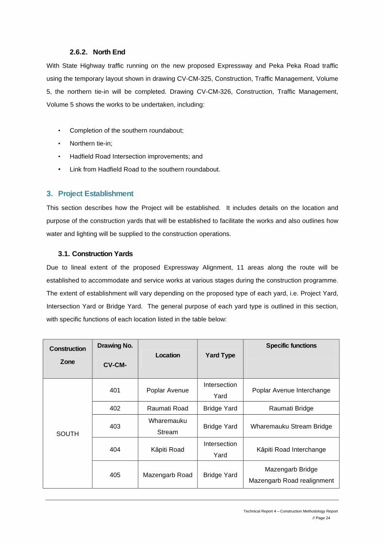
3.1. Construction Yards
Due to lineal extent of the proposed Expressway Alignment, 11 areas along the route will be
established to accommodate and service works at various stages during the construction programme.
The extent of establishment will vary depending on the proposed type of each yard, i.e. Project Yard,
Intersection Yard or Bridge Yard. The general purpose of each yard type is outlined in this section,
with specific functions of each location listed in the table below:
Construction
Zone
Drawing No.
CV-CM- Location Yard Type
Specific functions
SOUTH
401 Poplar Avenue Intersection
Yard Poplar Avenue Interchange
402 Raumati Road Bridge Yard Raumati Bridge
403 Wharemauku
Stream Bridge Yard Wharemauku Stream Bridge
404 Kāpiti Road Intersection
Yard Kāpiti Road Interchange
405 Mazengarb Road Bridge Yard Mazengarb Bridge
Mazengarb Road realignment
Technical Report 4 – Construction Methodology Report // Page 25
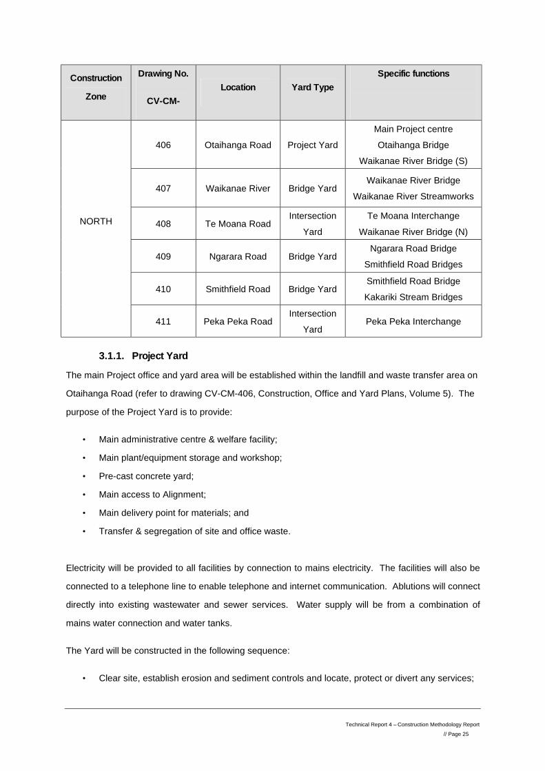
Construction
Zone
Drawing No.
CV-CM- Location Yard Type
Specific functions
NORTH
406 Otaihanga Road Project Yard Main Project centre Otaihanga Bridge
Waikanae River Bridge (S)
407 Waikanae River Bridge Yard Waikanae River Bridge
Waikanae River Streamworks
408 Te Moana Road Intersection
Yard Te Moana Interchange
Waikanae River Bridge (N)
409 Ngarara Road Bridge Yard Ngarara Road Bridge
Smithfield Road Bridges
410 Smithfield Road Bridge Yard Smithfield Road Bridge Kakariki Stream Bridges
411 Peka Peka Road Intersection
Yard Peka Peka Interchange
3.1.1. Project Yard
The main Project office and yard area will be established within the landfill and waste transfer area on
Otaihanga Road (refer to drawing CV-CM-406, Construction, Office and Yard Plans, Volume 5). The
purpose of the Project Yard is to provide:
• Main administrative centre & welfare facility;
• Main plant/equipment storage and workshop;
• Pre-cast concrete yard;
• Main access to Alignment;
• Main delivery point for materials; and
• Transfer & segregation of site and office waste.
Electricity will be provided to all facilities by connection to mains electricity. The facilities will also be
connected to a telephone line to enable telephone and internet communication. Ablutions will connect
directly into existing wastewater and sewer services. Water supply will be from a combination of
mains water connection and water tanks.
The Yard will be constructed in the following sequence:
• Clear site, establish erosion and sediment controls and locate, protect or divert any services;
Technical Report 4 – Construction Methodology Report // Page 26
• Realign existing access track to green waste area;
• Complete stormwater works, including modifications to outlet of transfer station and landfill
drainage;
• Cut back existing sand dune to profile shown on Drawing CV-CM-406, Construction, Office
and Yard Plans, Volume 5. The existing Otaihanga Road face of the dune will be preserved,
but the landfill face will be cut back further from its existing position to provide the required
space for the Yard;
• Cut material will be used to reshape the existing stormwater retention pond and form the base
for the yard area. A cut to fill balance is anticipated. The cut face will be topsoiled and
hydroseeded to protect it from erosion;
• Place aggregate to yard area and form accessway and car park areas. Seal where required
• Erect office units, fabrication units/moulds/cranes and plant workshop units; and
• Connect to services.
As part of this establishment and to mitigate the effects of increasing traffic in this area, the existing
intersection of Otaihanga Road with SH1 will be upgraded to a roundabout configuration.
The construction and operation of the Project Yard will be carefully managed to avoid disruption to the
existing KCDC transfer station and to ensure the safety of all using this facility.
3.1.2. Intersection Yards
At each Intersection location, an Intersection Yard will be established as the administrative centre for works in that particular area. The purpose of each Intersection Yard is to provide:
• Administrative centre & welfare facility for all works in the vicinity of the intersection;
• Local plant/equipment storage;
• Local access to Alignment;
• Delivery point for bridge construction materials; and
• Collection of site waste.
Electricity will be provided to the office facility by connection to mains electricity. The office will also
be connected to a telephone line to enable telephone and internet communication. Ablutions will
connect directly into existing waste services. Water supply will be from connection to the mains
water.
As shown in the drawings, each Intersection Yard will be positioned in an existing developed area.
The area will either by leased or the existing facilities will be utilised prior to their eventual removal as
Technical Report 4 – Construction Methodology Report // Page 27
part of the works. In this way, existing services, including stormwater drains, can be used for the
duration of the establishment.
3.1.3. Bridge Yards
In addition to the Intersection Yards, a small establishment will be set up at each bridge location. The purpose of each Bridge Yard will be to provide a small office and welfare facility specifically for the duration of the bridge construction works. Services provided will be:
• Welfare/small office facility;
• Local plant/equipment storage;
• Local access to Alignment;
• Delivery point for bridge construction materials; and
• Collection of site waste.
Electricity will be provided to the welfare/office facility by connection to mains electricity. Where
connection is not available of practicable, electricity supply will be from generators. No telephone
connection is anticipated for the Bridge Yards. Telephone and internet access, if necessary, will be
through wireless applications, but the main administration facility will be at the nearest Intersection
Yard or at the Project Yard.
Ablution blocks will connect directly into existing waste services. Alternatively, portaloos will be
provided, which will be emptied regularly. Where a piped wastewater connection is not available or
practicable, waste storage tanks will be used and will be pumped out regularly. Water supply will be
from a mains water connection, or tanks/bore if no connection is readily available.
3.2. Water supply
Where possible, and to minimise the impact on water resources, the reuse of water from sediment
retention devices will be used in construction operations. However, to ensure adequate supply of
water up to 9 deep water bores will be positioned along the proposed Expressway route. Potential
positions for the bores will be at the following locations to minimise haulage and are shown in the
drawing CV-CM-400 series (Construction, Office and Yard Plans, Volume 5):
1. Poplar Avenue
2. Raumati Road
3. Ihakara Street
4. Kāpiti Road
5. Mazengarb Road
Technical Report 4 – Construction Methodology Report // Page 28
6. Waikanae River
7. Te Moana Road
8. Ngarara Road
9. Peka Peka Road
Where necessary, these bores will also provide water supply to the office/welfare facility in the
construction yards.
During drier months and at peak construction periods in each bore locations, maximum supply of
water will need to be 800cum per day.
3.3. Construction Lighting
Lighting will be required in some construction areas to enable operations to proceed during the hours
of darkness.
3.3.1. Night work
In general, construction operations will occur during the day, unless operations are being carried out
on or adjacent to an existing road that will require working during off-peak traffic hours, i.e. at night.
Operations that are expected to be carried out during night time hours are:
1) Erection of bridges at: a. Raumati Road b. Kāpiti Road c. Mazengarb Road d. Otaihanga Road e. Te Moana Road f. Ngarara Road
2) East and West ends of Kāpiti Road Intersection
At these locations, the site and adjacent construction yard will require full illumination during the night
in order to complete the required operations. During the erection of the bridges at each of the above
locations, the precast yard on Otaihanga Road will also be fully lit to enable loading of bridge units.
Mobile lighting towers will be erected on a temporary basis for night works. These are designed to
allow work to be safely carried out in darkness, while minimising the effects of light spill on
neighbouring properties, due to the unique design of the lighting shields. Once erected, the site
Technical Report 4 – Construction Methodology Report // Page 29
engineer will be responsible for checking light spill nuisance effects on adjacent properties and
changing the angle of set up to resolve any issues.
3.3.2. Construction Yards
Each construction yard area will utilise temporary lighting to enable operations to proceed during the
hours of darkness. When night works are not in operation in these locations, the purpose of this
lighting will be to guide staff, plant and vehicles at the start and end of each shift and generally be
limited to winter months.
Where required, mobile lighting towers will be erected for these purposes and specifically designed to
allow work people/plant/vehicle movement to be safely carried out in darkness, while minimising the
effects of light spill on neighbouring properties. Once erected, the site engineer will be responsible for
checking light spill nuisance effects on adjacent properties and changing the angle of set up to
resolve any issues.
Security lighting for the construction yards will be designed and set up to minimise light pollution and
ensure appropriate light shielding occurs.
3.4. Construction Stormwater Drainage
Stormwater management during the construction phase is a separate and unique stage in the water management of the proposed Expressway. It occurs after earthworks activities have ceased in an area, and initial erosion and sediment controls may no longer be appropriate, but before long term operational stormwater controls are fully operational. Stormwater management measures are proposed for impervious construction areas and the pavement of the constructed proposed Expressway.
3.4.1. Haul Roads and Accesses
One of the principles of the ESCP is to utilise the eventual stormwater devices, i.e. stormwater retention ponds and swales drains, as run-off carriers and retentions. Sediment control will be installed within these stormwater devices until earthworks are complete and areas stabilised. In the period between earthworks completing and commissioning of the proposed Expressway, for example while the proposed Expressway route is being used as a haul road, the stormwater devices will continue to be used to carry and collect run-off. Appropriate sediment control will remain in place in the constructed swale drains and retention areas to capture any potential sediment from the haul roads.
Technical Report 4 – Construction Methodology Report // Page 30
3.4.2. Construction Yards
Stormwater drainage to the construction yard areas on the proposed Expressway Alignment and
adjacent to the proposed Expressway work activity will utilise nearby sediment control devices to
carry and retain run-off. The majority of the construction yards will be operational only during
construction activity in that area. Upon completion of the works, the yard will also be demobilised,
leaving the area to be stabilised and the stormwater devices used in sediment control converted to
permanent features.
In addition to this general principle, there are some specific stormwater management considerations
for particular construction yard areas:
• Kāpiti Road and Te Moana Road Intersection Yards
As shown in drawings CV-CM-404 and 408 (Construction, Office and Yard Plans, Volume 5),
existing, established buildings and car park areas are proposed as yard and office areas. The
existing stormwater systems from these areas will be checked for suitability. Any further
measures required will be designed in accordance with normal requirements from KCDC for such
sites.
• Project Yard, Otaihanga
The main Project office and yard area is located outside of the proposed Expressway Alignment
and is likely to remain in place for the entire duration of construction. A specific stormwater plan
has therefore been developed for this area.
The stormwater drainage for the Otaihanga Yard is shown on Drawing CV-CM-406, Construction,
Office and Yard Plans, Volume 5 and consists of the following components:
• Planted/grassed perimeter swales;
• Rock lined/stone bed open channel drains where larger drains are needed;
• A treatment and attenuation wetland with outlet pipe;
• Culverts under existing internal accessways; and ,
• Proprietary Drift Deck box culverts under existing internal accessways where cover to a
standard culvert cannot be achieved.
The wetland has been designed for treatment and attenuation of stormwater runoff from the
construction yard and it has been positioned in the same location as an existing wetland intended to
serve the Transfer Station. This existing wetland does not have a sediment forebay and it is overdue
Technical Report 4 – Construction Methodology Report // Page 31
for maintenance with a large amount of sediment covering its bed. The effect of this is to smother
planting, with the wetland essentially functioning as a sediment pond rather than the natural wetland
that was intended. smother
Positioning the new wetland in this location allows the current operational issues to be addressed at
the same time as providing stormwater treatment for the new yard. The existing basin will be
excavated, and if the material is contaminated, it will be disposed to a secure landfill. On completion
of the proposed Expressway it is possible that the construction yard wetland may not be removed,
instead becoming a permanent feature of Otaihanga Landfill area. Therefore, it has been designed to
the same standard as the other stormwater wetlands across the Project, i.e. to NZTA’s Stormwater
Treatment Standard for State Highway Infrastructure, 2010, with the principles governing the design
being the same as those discussed in detail in the Assessment of Hydrology and Stormwater Effects
(Technical Report 22, Volume 3) and particularly the typical wetland Drawing CV-SW-212 (Technical
Report Appendices, Report 22, Volume 5).
Runoff from the yard, offices, work shop and carpark will be drained into the wetland for treatment and
attenuation. Runoff from areas surrounding the yard will be diverted around the outside to existing
watercourses. In accordance with NZTA’s standard, the wetland is also sized to attenuate the 1%AEP
storm to 80% of existing peak runoff flows. The wetland will be 420m2 in area and has an active
volume above the permanent water level of 218m3 for attenuation during the 1%AEP storm. Further
design information for the wetland is shown on Drawing CV-CM-406, Construction, Office and Yard
Plans, Volume 5.
This wetland has not yet been modelled in InfoWorks software as the other wetlands were, because
the arrangement and shape of the construction yard may yet change. It also has not been modelled in
KCDC’s stormwater model for the same reasons. Detailed sizing in InfoWorks will be carried out in
later stages of the design.
As the yard is located on land that is generally at a reduced level of 9m, it is not within existing flood
areas and so will not impact on flood storage by in filling. Offset storage is therefore not a feature of
this wetland. The wetland will discharge into the top of the north branch of the Landfill Drain. The
outlet will be stabilised with rock rip rap and discharge from the wetland is not expected to have an
adverse effect the drain.
Technical Report 4 – Construction Methodology Report // Page 32
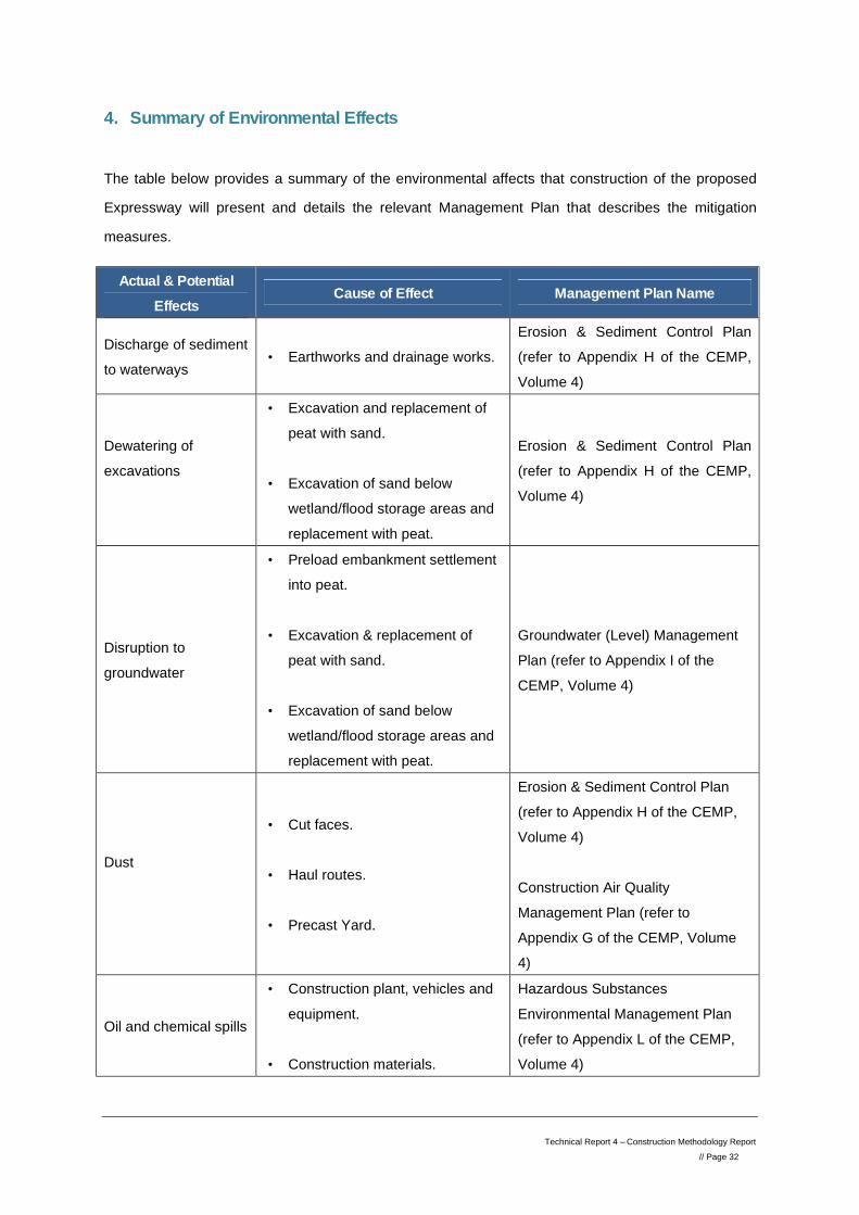
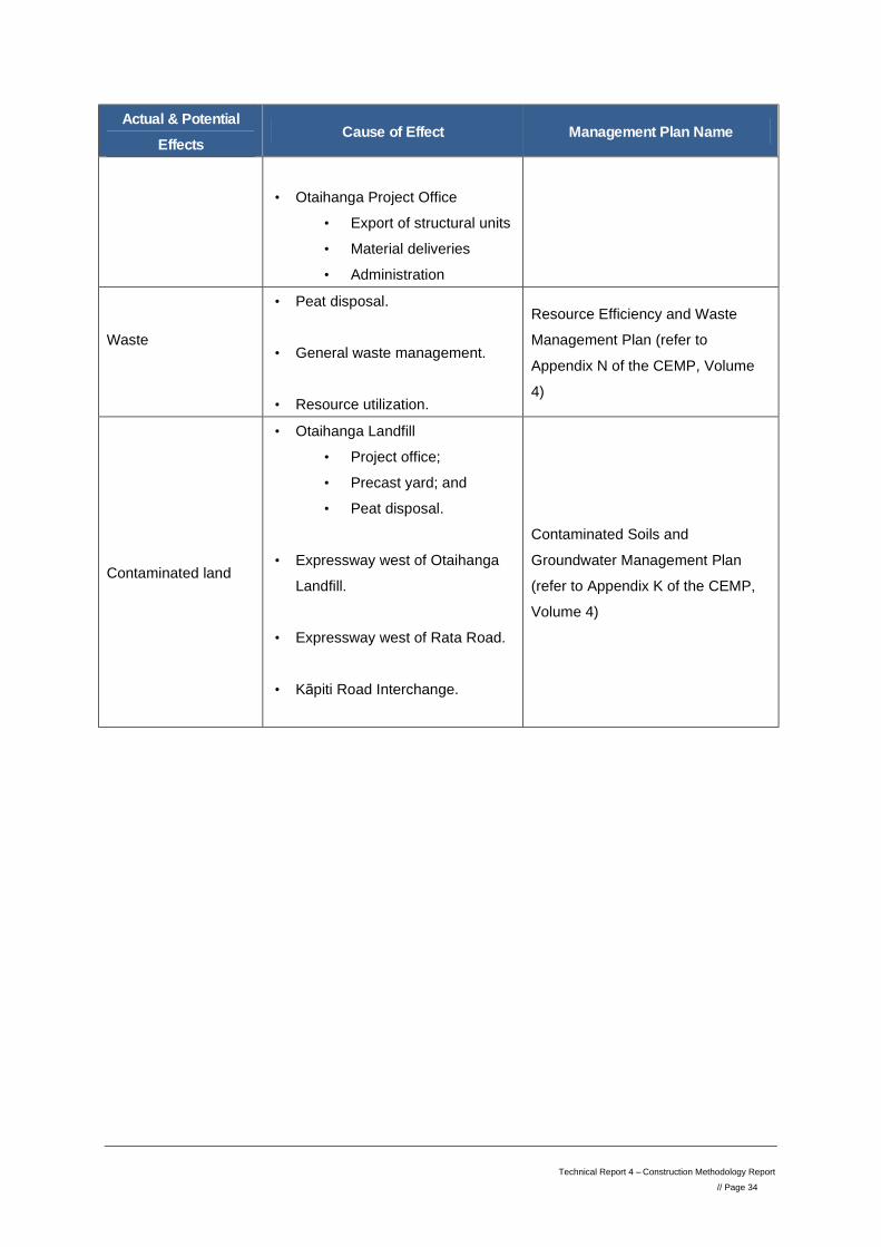
4. Summary of Environmental Effects
The table below provides a summary of the environmental affects that construction of the proposed
Expressway will present and details the relevant Management Plan that describes the mitigation
measures.
Actual & Potential Effects
Cause of Effect Management Plan Name
Discharge of sediment to waterways
• Earthworks and drainage works. Erosion & Sediment Control Plan (refer to Appendix H of the CEMP, Volume 4)
Dewatering of excavations
• Excavation and replacement of peat with sand.
• Excavation of sand below
wetland/flood storage areas and replacement with peat.
Erosion & Sediment Control Plan (refer to Appendix H of the CEMP, Volume 4)
Disruption to groundwater
• Preload embankment settlement into peat.
• Excavation & replacement of
peat with sand. • Excavation of sand below
wetland/flood storage areas and replacement with peat.
Groundwater (Level) Management Plan (refer to Appendix I of the CEMP, Volume 4)
Dust
• Cut faces. • Haul routes. • Precast Yard.
Erosion & Sediment Control Plan (refer to Appendix H of the CEMP, Volume 4) Construction Air Quality Management Plan (refer to Appendix G of the CEMP, Volume 4)
Oil and chemical spills
• Construction plant, vehicles and equipment.
• Construction materials.
Hazardous Substances Environmental Management Plan (refer to Appendix L of the CEMP, Volume 4)
Technical Report 4 – Construction Methodology Report // Page 33
Actual & Potential Effects
Cause of Effect Management Plan Name
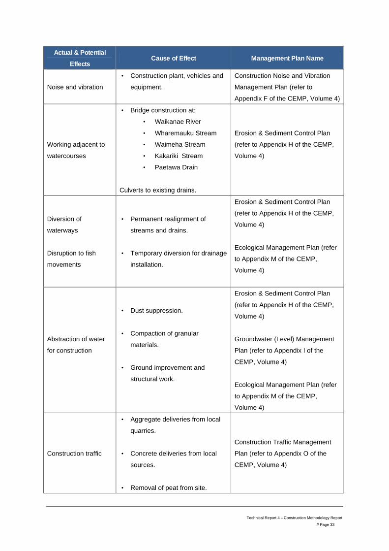
Noise and vibration • Construction plant, vehicles and
equipment.
Construction Noise and Vibration Management Plan (refer to Appendix F of the CEMP, Volume 4)
Working adjacent to watercourses
• Bridge construction at: • Waikanae River • Wharemauku Stream • Waimeha Stream • Kakariki Stream • Paetawa Drain
Culverts to existing drains.
Erosion & Sediment Control Plan (refer to Appendix H of the CEMP, Volume 4)
Diversion of waterways Disruption to fish movements
• Permanent realignment of streams and drains.
• Temporary diversion for drainage
installation.
Erosion & Sediment Control Plan (refer to Appendix H of the CEMP, Volume 4) Ecological Management Plan (refer to Appendix M of the CEMP, Volume 4)
Abstraction of water for construction
• Dust suppression. • Compaction of granular
materials. • Ground improvement and
structural work.
Erosion & Sediment Control Plan (refer to Appendix H of the CEMP, Volume 4) Groundwater (Level) Management Plan (refer to Appendix I of the CEMP, Volume 4) Ecological Management Plan (refer to Appendix M of the CEMP, Volume 4)
Construction traffic
• Aggregate deliveries from local quarries.
• Concrete deliveries from local
sources. • Removal of peat from site.
Construction Traffic Management Plan (refer to Appendix O of the CEMP, Volume 4)
Technical Report 4 – Construction Methodology Report // Page 34
Actual & Potential Effects
Cause of Effect Management Plan Name
• Otaihanga Project Office
• Export of structural units • Material deliveries • Administration
Waste
• Peat disposal. • General waste management. • Resource utilization.
Resource Efficiency and Waste Management Plan (refer to Appendix N of the CEMP, Volume 4)
Contaminated land
• Otaihanga Landfill • Project office; • Precast yard; and • Peat disposal.
• Expressway west of Otaihanga
Landfill. • Expressway west of Rata Road. • Kāpiti Road Interchange.
Contaminated Soils and Groundwater Management Plan (refer to Appendix K of the CEMP, Volume 4)