Embed Size (px)
Citation preview
DAVID A. BERNSTEIN
U. S. Forest ServicePortland, Oregon
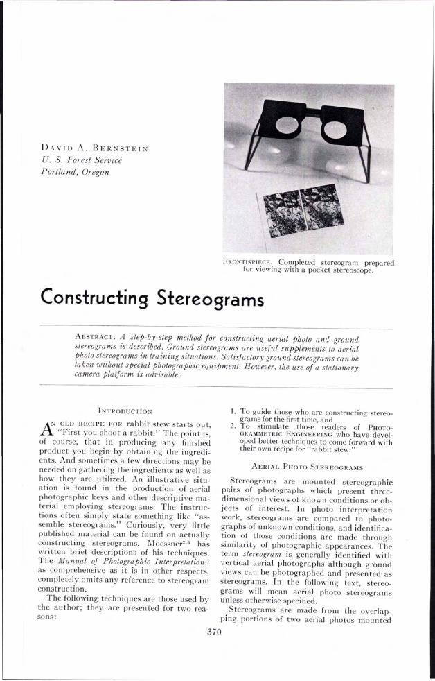
FRONTISPIECE. Completed stereogram preparedfor viewing with a pocket stereoscope.
Constructing Stereograms
ABSTRACT: A step-by-step method for constructing aerial photo and groundstereograms is described. Ground stereograms are useful supplements to aerialphoto stereograms in training situations. Satisfactory ground stereograms can betaken without special photographic equipment. However, the use of a stationarycamera platform is advisable.
I TRODUCTION
AN OLD RECIPE FOR rabbi t stew starts ou t,rt "First you shoot a rabbit." The point is,of course, that in producing any finishedproduct you begin by obtaining the ingredients. And sometimes a few directions may beneeded on gathering the ingredients as well ashow they are utilized. An illustrative situation is found in the production of aerialphotographic keys and other descriptive material employing stereograms. The instructions often simply state something like "assemble stereograms." Curiously, very littlepublished material can be found on actuallyconstructing stereograms. Moessner2 •3 haswritten brief descriptions of his techniques.The Manual of Photographic Interpretation,'as comprehensive as it is in other respects,completely omits any reference to stereogramconstruction.
The following techniques are those used bythe author; they are presented for two reasons:
1. To guide those who are constructing stereograms for the first time, and
2. To stimulate those readers of PHOTOGRAMMETRIC ENGINEERING who have developed better techniques to come forward withtheir own recipe for "rabbit stew."
AERIAL PHOTO STEREOGRAMS
Stereograms are mounted stereographicpairs of photographs which present thrcedimensional views of known conditions or objects of interest. In photo interpretationwork, stereograms are compared to photographs of unknown conditions, and identification of those condi tions are made throughsimilarity of photographic appearances. Theterm stereogram is generally identified withvertical aerial photographs although groundviews can be photographed and presented asstereograms. In the following text, stereograms will mean aerial photo stereogramsunless otherwise specified.
Stereograms are made from the overlapping portions of two aerial photos moun ted
370
CONSTRUCTING STEREOGRAMS 371
same relative position on the other photo ofthe pair but make it parallel to the flight lineof that photo.
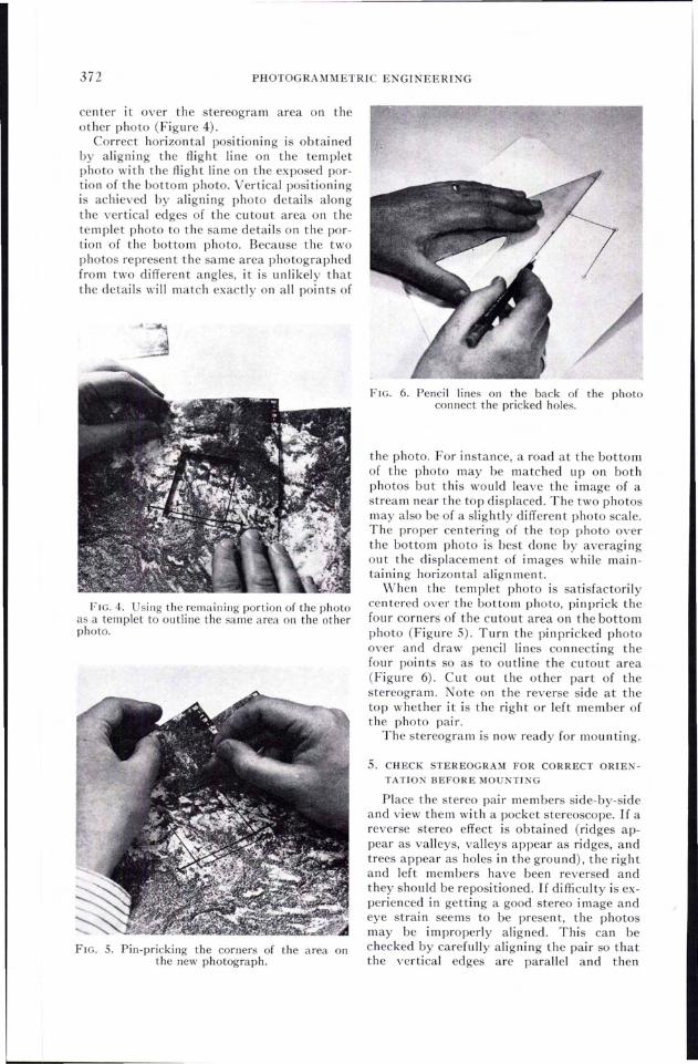
3. REMOVE STEREOGRAM FROM PHOTO
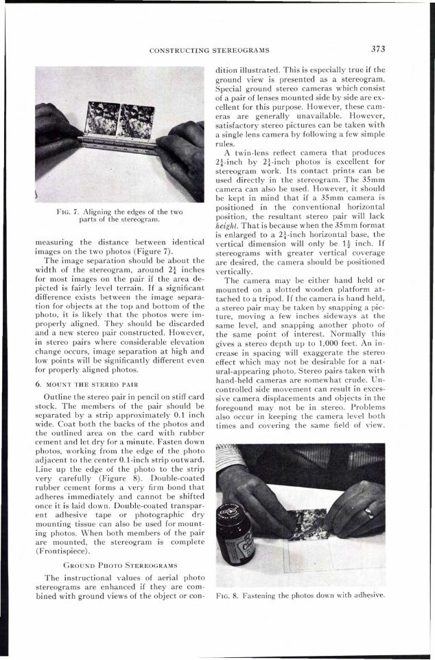
Cut out stereogram from photo (Figure 2).Wipe off grease pencil marks from face ofphoto. Note whether it is the right or leftmember of the photo pair on the reverse sideat the photo top (Figure 3).
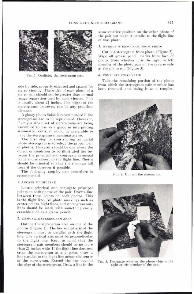
FIG. 1. Outlining the stereogram area.
side by side, properly i3uented and spaced forstereo viewing. The width of each photo of astereo pair should not be greater than normalimage separation used by most viewers. Thisis usually abou t 2t inches. The heigh t of thestereograms, however, can be any practicaldistance.
A glossy photo finish is recommended if thestereograms are to be reprod uced. However,if only a single set of tereograms are beingassembled to use as a guide in interpretingsemimatte prints, it would be preferable tohave the stereograms in semi matte also.
The first step in constructing an aerialphoto stereogram is to select the proper pairof photos. This pair should be one where theobject Ot- condi tion to be ill ustrated lies between the principal and conjugate principalpoint and is closest to the flight line. Photosshould be oriented so that the shadows falltoward the observer if possible.
The following step-by-step procedure isrecom mended.
1. LOCATE FLIGHT LINE
Locate principal and conjugate principalpoints on both photos of the pair. Draw a linebetween these poin ts on both photos. Thisis the flight line. All photo markings such ascenter points, flight lines, and stereogram outlines should be made with something easilyerasable such as a grease pencil.
2. DESIGNATE STEREOGRAM AREA
Outline the stereogram area on one of thephotos (Figure 1). The horizontal axis of thestereogram must be parallel with the flightline. The vertical axis must be perpendicularto the flight line. Keep in mind that thestereogram pair members should be no morethan 2t inches wide. If the flight line does notcross the stereogram at any point, draw aline parallel to the flight line act'Oss the centerof the stereogram. Extend the line beyondthe edge of the stereogram. Draw a line in the
4. COMPLETE STEREO PAIR
Take the remai ni ng portion of the photofrom which the stereogram pair member hasbeen removed and, using it as a templet,
FIG. 2. Cut out the stereogram.
FIG. 3. Designate whether the photo chip IS theright or left member of the pair.
372 PHOTOGRAMMETRIC ENGINEERING
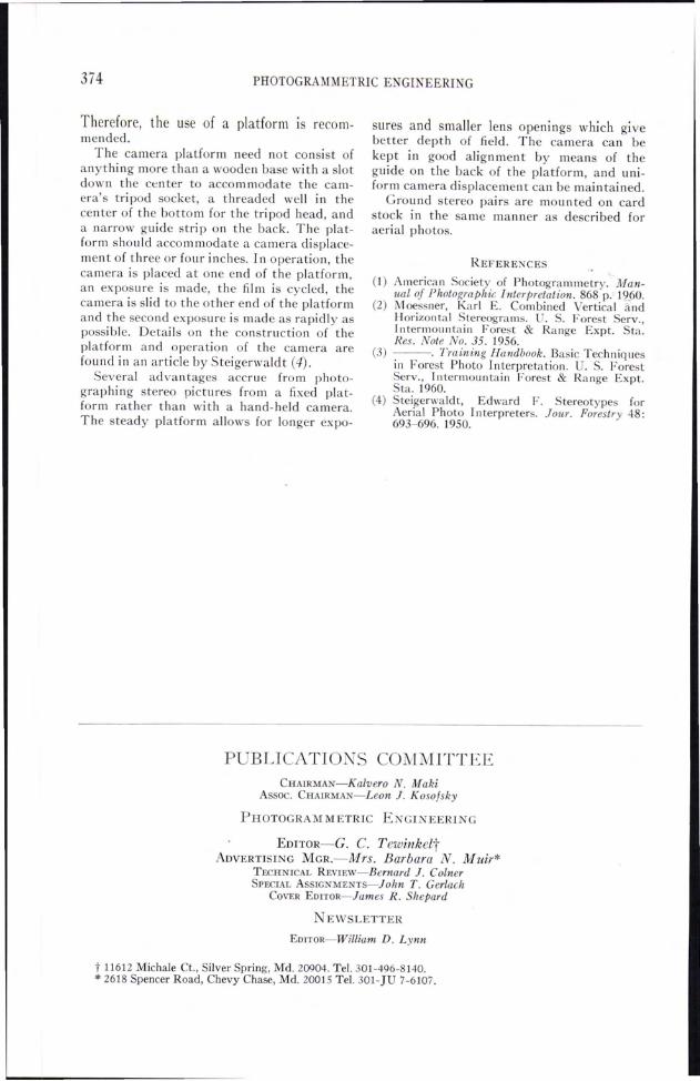
center it over the stereogram area on theother photo (Figure 4).
Correct horizontal positioning is obtainedby aligning the flight line on the templetphoto with the flight line on the exposed portion of the bottom photo. Vertical positioningis achieved by aligni ng photo details alongthe vertical edges of the cu tou t area on thetemplet photo to the same details on the portion of the bottom photo. Because the twophotos represen t the same area photographedfrom two different angles, it is unlikely thatthe details will match exactly on all points of
FIG. 4. Using the remaining portion of the photoas a templet to outline the same area on the otherphoto.
FIG. S. Pin-pricking the corners of the area onthe new photograph.
/'
FIG. 6. Pencil lines on the back of the photoconnect the pricked holes.
the photo. For instance, a road at the bottomof the photo may be matched upon bothphotos but this would leave the image of astream near the top displaced. The two photosmay also be of a slightly different photo scale.The proper cen teri ng of the top photo overthe bottom photo is best done by averagi ngout the displacement of images while maintaining horizontal alignment.
When the templet photo is satisfactorilycentered over the bottom photo, pinprick thefour corners of the cutout area on the bottomphoto (Figure 5). Turn the pin pricked photoover and draw pencil lines connecting thefour points so as to outline the cutout area(Figure 6). Cut out the other part of thestereogram. Note on the reverse side at thetop whether it is the right or left member ofthe photo pair.
The stereogram is now ready for mounting.
S. CHECK STEREOGRAM FOR CORRECT ORIEN
TATION BEFORE MOUNTING
Place the stereo pair members side-by-sideand view them with a pocket stereoscope. If areverse stereo effect is obtained (ridges appear as valleys, valleys appear as ridges, andtrees appear as holes in the ground), the rightand left members have been reversed andthey should be repositioned. If difficulty is experienced in getting a good stereo image andeye strain seems to be present, the photosmay be improperly aligned. This can bechecked by carefully aligning the pair so thatthe vertical edges are parallel and then
CONSTRUCTING STEREOGRAMS 373
dition illustrated. This is especially true if theground view is presented as a stereogram.Special ground stereo cameras which consistof a pair of lenses mounted side by side are excellent for this purpose. However, these cameras are generally unavailable. However,satisfactory stereo pictures can be taken witha single lens camera by following a few simplerules.
A twin-lens reAect camera that produces2i-inch by 2i-inch photos is excellent forstereogram work. Its contact prints can beused directly in the stereogram. The 35 m mcamera can also be used. However, it shouldbe kept in mind that if a 35mm camera ispositioned in the conventional horizontalposition, the resultant stereo pair will lackheight. That is because when the 35mm formatis enlarged to a 2i-inch horizontal base, thevertical dimension will only be It inch. Ifstereograms wi th greater vertical coverageare desired, the camera should be posi tionedvertically.
The camera may be either hand held ormounted on a slotted wooden platform attached to a tripod. If the camera is hand held,a stereo pair may be taken by snapping a picture, moving a few inches sideways at thesame level, and snapping another photo ofthe same point of interest. Normally thisgives a stereo depth up to 1,000 feet. An increase in spacing will exaggerate the stereoeffect which may not be desirable for a natural-appearing photo. Stereo pairs taken withhand-held cameras are somewhat crude. Uncontrolled side movement can result in excessive camera displacements and objects in theforegound may not be in stereo. Problemsalso occur in keeping the camera level bothtimes and covering the same field of view.
FIG. 7. Aligning the edges of the twoparts of the stereogram.
6. MOUNT THE STEREO PAIR
Outline the stereo pair in pencil on stiff cardstock. The members of the pair should beseparated by a strip approximately 0.1 inchwide. Coat both the backs of the photos andthe outlined area on the card with rubbercement and let dry for a minute. Fasten downphotos, working from the edge of the photoadjacent to the center O.l-inch strip outward.Line up the edge of the photo to the stripvery carefully (Figure 8). Double-coatedrubber cement forms a very firm bond thatadheres immediately and cannot be shiftedonce it is laid down. Double-coated transparent adhesive tape or photographic drymounting tissue can also be used for mounting photos. When both members of the pairare mounted, the stereogram is complete(Fron tispiece).
GROUND PHOTO STEREOGRAMS
The instructional values of aerial photostereograms are enhanced if they are com-bined with ground views of the object or con- FIG. 8. Fastening the photos down with adhesive.
measuring the distance between identicalimages on the two photos (Figure 7).
The image separation should be about thewidth of the stereogram, around 2i inchesfor most images on the pair if the area depicted is fairly level terrain. If a significantdifference exists between the image separation for objects at the top and bottom of thephoto, it is likely that the photos were improperly aligned. They should be discardedand a new stereo pair constructed. However,in stereo pairs where considerable elevationchange occurs, image separation at high andlow points will be significantly different evenfor properly aligned photos.
374 PHOTOGRAMMETRIC EI GINEERING
Therefore, the use of a platform IS recommended.
The camera platform need not consist ofanything more than a wooden base with a slotdown the center to accommodate the camera's tripod socket, a threaded well in thecen ter of the bottom for the tri pod head, anda narrow guide stri p on the back. The platform should accommodate a camera displacement of three or four inches. In operation, thecamera is placed at one end of the platform,an exposure is made, the film is cycled, thecamera is slid to the other end of the platformand the second exposure is made as rapidly aspossible. Details on the construction of theplatform and operation of the camera arefound in an article by Steigerwaldt (4).
Several advantages accrue from photographing stereo pictures from a fixed platform rather than wi th a hand-held camera.The steady platform allows for longer expo-
sures and smaller lens openings which givebetter depth of field. The camera can bekept in good alignment by means of theguide on the back of the platform, and uniform camera displacement can be maintained.
Ground stereo pairs are mounted on cardstock in the same manner as described foraerial photos.
REFERENCES
(1) American Society of Photogrammetry. M~an
ual of Photographic Interpretation. 868 p.' 1(?-60.(2) Moessner, Karl E. Combined Vertical and
Horizontal Stereograms. . S. Forest Serv.,Intermountain Forest & Range Expt. Sta.Res. Note No. 35. 1956.
(3) ---. Training Handbook. Basic Techniquesin Forest Photo Interpretation. U. S. ForestServ., Intermountain Forest & Range Expt.Sta. 1960.
(4) Steigerwaldt, Edward F. Stereotypes forAerial Photo Interpreters. Jour. Forestry 48:693-696. 1950.
PUBLICATION S COMMITTEECHAIRMAN-Kalvero N. Maki
Assoc. CHAIRMAN-Leon J. Koso/sky
PHOTOGRAMMETRIC ENGINEERING
EDITOR-G. C. TewinkeltADVERTISING MGR.-Mrs. Barbara N. Muir*
TECHNICAL REVIEw-Bernard 1. CoinerSPECIAL ASSIGNMENTs-John T. Gerlach
COVER EDITOR-James R. Shepard
I EWSLETTER
EDITOR-William D. Lynn
t 11612 Michale Ct., Silver Spring, Md. 20904. Tel. 301-496-8140.* 2618 Spencer Road, Chevy Chase, Md. 20015 Tel. 301-JU 7-6107.